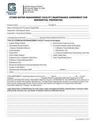
- Page 1 and 2: GREENVILLE COUNTY STORM WATER MANAG
- Page 3 and 4: 3.10.1 Purpose ....................
- Page 5 and 6: 8.4.2 Design of Riprap Channel Lini
- Page 7 and 8: LIST OF TABLES Table Name Page# Tab
- Page 9 and 10: Figure 8-10 Subsurface Draiange Cap
- Page 11: Standard Drawing WQ-08 Standard Dra
- Page 15 and 16: Chapter 1. INTRODUCTION 1.1 Purpose
- Page 17 and 18: Effects of Urbanization on Watershe
- Page 19 and 20: Utilize nontraditional lot designs
- Page 21 and 22: South Carolina Storm Water Manageme
- Page 23 and 24: Nothing in the Storm Water Manageme
- Page 25 and 26: Chapter 2. STORM WATER MANAGEMENT R
- Page 27 and 28: Technical Report The technical repo
- Page 29 and 30: The Greenville County Storm Water P
- Page 31 and 32: Chapter 3. PLAN SUBMITTAL 3.1 Storm
- Page 33 and 34: flooding or water quality or other
- Page 35 and 36: Plan. However, concurrence in the c
- Page 37 and 38: interfere with access to the easeme
- Page 39 and 40: Agency, and does not require prepar
- Page 41 and 42: 3.3.3 Storm Water Management Design
- Page 43 and 44: Design details and computation for
- Page 45 and 46: of the Clean Water Act; Description
- Page 47 and 48: 1. Restrict or prohibit uses that a
- Page 49 and 50: Each permit must include: Floodplai
- Page 51 and 52: water in storm water management fac
- Page 53 and 54: 3.4 Digital Submittal Requirements
- Page 55 and 56: 3.5.3 Incomplete Storm Water Manage
- Page 57 and 58: Final Storm Water Management Site P
- Page 59 and 60: 2. The owner has obtained applicabl
- Page 61 and 62: 2. Upgrade of Existing Detention or
- Page 63 and 64:
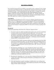
standards. The following conditions
- Page 65 and 66:
Chapter 4. EASEMENTS 4.1. Purpose A
- Page 67 and 68:
left hand corner of the plat. No ot
- Page 69 and 70:
equired, only the SCS Method or oth
- Page 71 and 72:
Description of Area Runoff Coeffici
- Page 73 and 74:
The SCS CN Method begins with a rai
- Page 75 and 76:
Use Figure 5-1 (Composite CN) if th
- Page 77 and 78:
5.2.3.3. Factors Affecting the Time
- Page 79 and 80:
Diversion, Swales, Paved gutters, R
- Page 81 and 82:
T c : Time of concentration (T c )
- Page 83 and 84:
Mild slopes less than 2 percent. Si
- Page 85 and 86:
484 300 t/Tt q/qu Q/Qp q/qu Q/Qp 3.
- Page 87 and 88:
triangular approximation, k r = t r
- Page 89 and 90:
5.6.2 Normalized Peak Flow Rate If
- Page 91 and 92:
Rainfall-runoff calculations carrie
- Page 93 and 94:
Chapter 6. HYDRAULICS 6.1. Open Cha
- Page 95 and 96:
6.1.3 Momentum Equation The momentu
- Page 97 and 98:
Type of Flow Media Min Normal Max N
- Page 99 and 100:
The hydraulic radius (R) for a trap
- Page 101 and 102:
Rearrangement of the continuity equ
- Page 103 and 104:
Water quality and channel protectio
- Page 105 and 106:
all three equations should be utili
- Page 107 and 108:
6.3.4 Critical Depth in Culverts Wh
- Page 109 and 110:
Select entrance coefficient K e fro
- Page 111 and 112:
Type of Structure and Design of Ent
- Page 113 and 114:
Therefore, Inlet Control prevails a
- Page 115 and 116:
6.4.3 Flow Through a Rock Ditch Che
- Page 117 and 118:
Stage (m) Flow Length (m) Unit Flow
- Page 119 and 120:
6.5.1.4 Pipe Size The minimum pipe
- Page 121 and 122:
where backwater effects created fro
- Page 123 and 124:
2) Knowing the channel dimensions,
- Page 125 and 126:
Table 6-5. Maximum Permissible Velo
- Page 127 and 128:
Chapter 7. STORM WATER DETENTION DE
- Page 129 and 130:
Evaluate the control structure outl
- Page 131 and 132:
6. Access: Maintenance access shall
- Page 133 and 134:
4. Access Port: Access to the subsu
- Page 135 and 136:
asin area. In calculating runoff vo
- Page 137 and 138:
equirements, The downstream propert
- Page 139 and 140:
times gully erosion is formed on th
- Page 141 and 142:
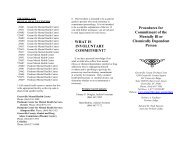
8.2. Purpose This chapter of the De
- Page 143 and 144:
8.3.2 Alternative Erosion Preventio
- Page 145 and 146:
Manning’s n of matting: 0.025 Sid
- Page 147 and 148:
**If side slopes were less than 3:1
- Page 149 and 150:
V S = Y D W * 43,560 Where V S is t
- Page 151 and 152:
If construction of a particular sit
- Page 153 and 154:
are located Appendix F and include:
- Page 155 and 156:
must be obtained. For Greenville Co
- Page 157 and 158:
Solution: Part (a) 1. Estimate the
- Page 159 and 160:
If the ditch check ratio intersects
- Page 161 and 162:
8.7.4.1 Silt Fence Design Aid Ratio
- Page 163 and 164:
B. 1. A Cecil D 15 topsoil is 0.006
- Page 165 and 166:
A sediment storage volume shall be
- Page 167 and 168:
Chapter 9. WATER QUALITY 9.1. Water
- Page 169 and 170:
lakes (US EPA, 1997). Such nutrient
- Page 171 and 172:
Table 9-4. Event Mean Concentration
- Page 173 and 174:
Event mean pollutant concentrations
- Page 175 and 176:
Permanent water quality ponds and d
- Page 177 and 178:
only the permanent pools of storm w
- Page 179 and 180:
9.7. Non-Structural Water Quality C
- Page 181 and 182:
A ( K T ) = cd I [( ) − K] Where:
- Page 183 and 184:
General Structural Control Sand Fil
- Page 185 and 186:
BMP TSS TP TN Estimated Pollutant R
- Page 187 and 188:
Limited Structural Control Vegetate
- Page 189 and 190:
equired water quality standard. For
- Page 191 and 192:
Chapter 10. LOW IMPACT DEVELOPMENT
- Page 193 and 194:
Minimize imperviousness by reducing
- Page 195 and 196:
10.1.1.5.1 Residential Residential
- Page 197 and 198:
Maximize sheet flow Modify/ lengthe
- Page 199 and 200:
Table 10-3. LID Techniques for use
- Page 201 and 202:
from infiltration. The results of t
- Page 203 and 204:
volume control, needed to maintain
- Page 205 and 206:
Table 10-4. Site Constraints of LID
- Page 207 and 208:
Chapter 11. STREAM PROTECTION AND R
- Page 209 and 210:
advantages. Vegetated measures prov
- Page 211 and 212:
Frequency of bank-full flow based o
- Page 213 and 214:
with geotextiles and geogrids suppl
- Page 215 and 216:
Date and location of the site inspe
- Page 217 and 218:
Failure to comply with the storm wa
- Page 219 and 220:
on the property, and payment of all