INSTRUCTION MANUAL
INSTRUCTION MANUAL
INSTRUCTION MANUAL

You also want an ePaper? Increase the reach of your titles
YUMPU automatically turns print PDFs into web optimized ePapers that Google loves.
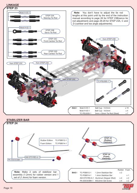
LINKAGE<br />
STEP 23<br />
Mold H-03-1<br />
Mold H-02-1<br />
STEP 23A<br />
Steering Tie Rod<br />
STEP 23B<br />
Servo Tie Rod<br />
Note: You don’t have to adjust the tie rod<br />
lengths at this point until by the end of the instruction<br />
manual according to page 26 for STEP 23B(servo tie<br />
rod adjustment) and page 28-29 for STEP 23A, C and<br />
D (camber and toe angle adjustments).<br />
STEP 23C<br />
Front Camber Tie Rod<br />
from STEP 23D<br />
STEP 23D<br />
Rear Camber Tie Rod<br />
from STEP 23C<br />
from STEP 23A<br />
from STEP 23C<br />
TC-PSU005-1*<br />
BAG I Mold H-02-1 Ball Cup - 14.5mm x 10<br />
Mold H-03-1 Ball Cup - 18.5mm x 4<br />
TC-PSU005-1 3mm x 30mm Tie Rod (Steel) x 7<br />
STABILIZER BAR<br />
STEP 24<br />
Rubber Edition:<br />
Foam Edition:<br />
TC-PSB012-1<br />
TC-PSB014-1<br />
STEP 24<br />
(Rubber)<br />
FINISHED<br />
PA-SS0303BK-1<br />
AW-ST01RD-A-1<br />
STEP 24<br />
(Foam)<br />
FINISHED<br />
Note: Make 2 sets of stabilizer bar<br />
assembly (1.2mm) for rubber version and 1<br />
set of (1.4mm) for foam version.<br />
Rubber Foam<br />
BAG I TC-PSB012-1 1.2mm Stabilizer Bar x 2<br />
TC-PSB014-1 1.4mm Stabilizer Bar x 1<br />
AW-ST01RD-A-1 Aluminum Stopper (Red) x 4 x 2<br />
PA-SS0303BK-1 M3x3mm Set Screw x 4 x 2<br />
Page 19