

EY15V, EY20V - Small Engine Discount
EY15V, EY20V - Small Engine Discount
EY15V, EY20V - Small Engine Discount

Create successful ePaper yourself
Turn your PDF publications into a flip-book with our unique Google optimized e-Paper software.
6. MAGNETO<br />
6-1 MAGNETO<br />
The spark for ignition is furnished by a magneto assembly. The magneto consists of a flywheel, ignition coil<br />
and contact breaker assembly (including condenser), of which flywheel is mounted on crankshaft and ignition<br />
coil contact breaker are mounted in crankcase directly. The <strong>EY20V</strong> type engine normally incorporates a<br />
solid state ignition system (T.I.C.) described in 6.5 "SOLID STATE IGNITION."<br />
/<br />
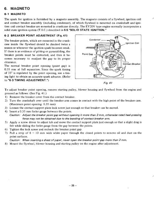
6-2 BREAKER POINT ADJUSTMENT (Fig.41)<br />
The breaker points, which are mounted in the crankcase<br />
inside the flywheel should be checked twice a<br />
season or whenever the ignition spark becomes weak.<br />
If there is an evidence of pitting or pyramidding, the<br />
breaker points must be corrected, and then it becomes<br />
necessary to readjust the gap to its proper<br />
clearance.<br />
The normal breaker point opening (point gap) is<br />
0.35 mm at full separation. Since the spark timing<br />
of 23" is regulated by the point opening, use a timing<br />
light to obtain an accurate spark advance. (Refer<br />
to "6-3 TIMING ADJUSTMENT.")<br />
Fig. 4 1<br />
To adjust breaker point opening, remove starting pulley, blower housing and flywheel from the engine and<br />
proceed as follows: (See Fig. 41.)<br />
Remove the breaker cover from the ,<br />
Turn the crankshaft over until the breaker arm comes in contact with the high point of the breaker cam.<br />
(Maximum point opening: 0.35 mm)<br />
Loosen the contact support plate lock screw just enough so that breaker can be moved.<br />
Insert a 0.35 mm feeler gauge between the points.<br />
Caution: Adjust the breaker point gap without opening it more than 2 mm, otherwise rated heel-pressing<br />
force may not be obtained due to the bending of contact breaker arm.<br />
Apply a screw driver to adjust tab and move the contact support plate just enough so that a slight drag is<br />
felt while sliding the feeler gauge from the gap between the points.<br />
Tighten the lock screw and recheck the breaker point gap.<br />
Pull a strip of 8 - 10 mm wide white paper through the closed points to remove oil and dust on the<br />
point surfaces.<br />
Caution: When inserting a sheet of paper, never open the breaker point gap more than 2 mm.<br />
Mount the flywheel, blower housing and starting pulley on the engine after adjustment.<br />
- 28 -


