1686-e_SL-PLUS MIA.indd
1686-e_SL-PLUS MIA.indd
1686-e_SL-PLUS MIA.indd

Create successful ePaper yourself
Turn your PDF publications into a flip-book with our unique Google optimized e-Paper software.
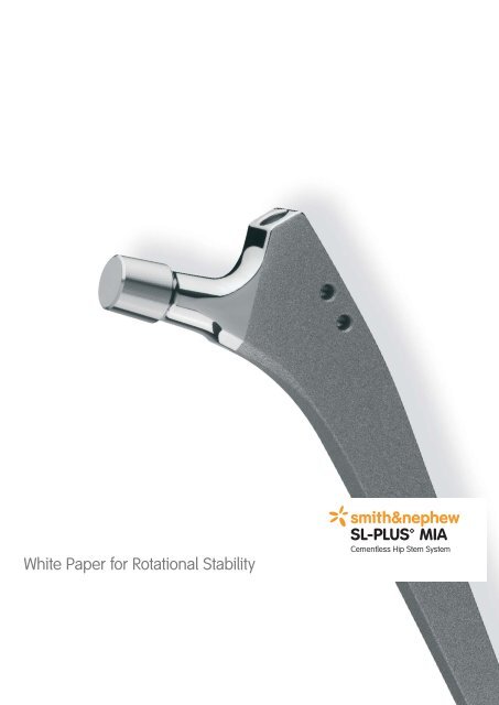
White Paper for Rotational Stability<br />
*smith&nephew<br />
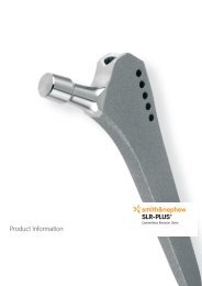
<strong>SL</strong>-<strong>PLUS</strong> <strong>MIA</strong><br />
Cementless Hip Stem System
<strong>SL</strong>-<strong>PLUS</strong> <strong>MIA</strong><br />
Building on the long-term success of the <strong>SL</strong>-<strong>PLUS</strong> hip stem, the <strong>SL</strong>-<strong>PLUS</strong> <strong>MIA</strong> hip stem has been<br />
developed for minimally invasive surgical procedures. The design and surgical technique of this<br />
stem allow implantation with reduced lateral bone resection, preserving the tendons on the greater<br />
trochanter. The anchoring technique of the modified, dual-taper straight stem in the region of the<br />
lateral shoulder in the diaphysis is fully maintained (fig. 1, 2). The aim of this paper is to investigate<br />
the impact of the modified shoulder on the rotational stability of the <strong>SL</strong>-<strong>PLUS</strong> <strong>MIA</strong> Standard stem<br />
compared with the <strong>SL</strong>-<strong>PLUS</strong> Standard stem.<br />
Due to the complex geometric conditions and biomechanics, the finite element (FEM) method is<br />
frequently utilized (3, 4, 5, 6, 7) to calculate the load distribution, displacement and the system<br />
performance in general. This method is particularly suitable for comparative calculations to evaluate<br />
various designs.<br />
02
<strong>SL</strong>-<strong>PLUS</strong> <strong>MIA</strong><br />
Materials and methods<br />
This analysis compares the <strong>SL</strong>-<strong>PLUS</strong> Standard stem size 6 and the <strong>SL</strong>-<strong>PLUS</strong> <strong>MIA</strong> Standard stem size 6<br />
in terms of their primary rotational stability using FEM calculations. A numerical 3D model of the femur<br />
was used to represent the bone. The cortical and cancellous bone were modeled separately (please<br />
refer to table 1 for material properties) and the hip stems to be studied were virtually implanted into<br />
the model bone. In both cases the size 6 stem achieved good cortical contact in the virtually rasped<br />
bony bed of the distal femur (fig. 1C) thereby reflecting the immediate postoperative situation.<br />
Cortical fixation<br />
of the stem<br />
A B C<br />
Fig. 1: Implanted hip stem in the bone model <strong>SL</strong>-<strong>PLUS</strong> <strong>MIA</strong> Standard (A), and <strong>SL</strong>-<strong>PLUS</strong> Standard (B). In the semi-transparent<br />
model the cancellous bone is shown in orange. Figure C shows a cross section through the femur.<br />
The <strong>SL</strong>-<strong>PLUS</strong> <strong>MIA</strong> Standard stem is less prominent in the proximal/lateral femur than the <strong>SL</strong>-<strong>PLUS</strong> Standard<br />
stem (fig. 1). In accordance with the clinical procedure, care was also taken to ensure that both stems<br />
were primarily fixed into the cortical region of the diaphysis. Due to the different implant techniques,<br />
the greater trochanter major is weakened to a greater extent with the <strong>SL</strong>-<strong>PLUS</strong> Standard stem than with<br />
the <strong>SL</strong>-<strong>PLUS</strong> <strong>MIA</strong> Standard stem (fig. 2).<br />
Fig. 2: Proximal view of the femur with the <strong>SL</strong>-<strong>PLUS</strong> <strong>MIA</strong> Standard stem (left) and the <strong>SL</strong>-<strong>PLUS</strong> Standard stem (right).<br />
The difference in the trochanter weakening caused by the implantation techniques can be clearly seen.<br />
03
The 3D geometries were imported into a finite element program for further processing and loading<br />
(pre- and post-processing program MSC Patran, network with approximately 60’000 tetrahedron<br />
elements). Friction at the implant/bone surfaces of the anchoring was established with a friction<br />
coefficient of 0.5.<br />
Elasticity module Poisson ration Element types Source<br />
Cortical bone 25’000 N/mm 2 0.3 Tet-4, 4 mm [1]<br />
Cancellous bone 1’500 N/mm 2 0.3 Tet-4, 2 mm [1]<br />
Titanium 110’000 N/mm 2 0.3 Tet-4, 1 mm [2]<br />
Table 1: Material properties for the FEM calculation.<br />
Based on Bergmann et al. [8] a torsional moment of approximately 16 Nm was applied as a load<br />
along the longitudinal axis of each stem. The bone was secured distally at the isthmus. The displacement<br />
of the ball head center, representing rotational stability in this model, was calculated,<br />
as was the interface load transmission in the region of the implant/bone interface.<br />
Mz = 16 Nm<br />
A<br />
B<br />
C<br />
Fig. 3: FEM models of the femora with <strong>SL</strong>-<strong>PLUS</strong> <strong>MIA</strong> Standard (A), and <strong>SL</strong>-<strong>PLUS</strong> Standard (B). A torsional moment (C) was<br />
applied along the longitudinal axis of the stem.<br />
04
<strong>SL</strong>-<strong>PLUS</strong> <strong>MIA</strong><br />
Results<br />
1. Displacement of the overall system<br />
The maximum displacement values of the ball head center were approximately 0.211 mm for the<br />
<strong>SL</strong>-<strong>PLUS</strong> <strong>MIA</strong> Standard stem and approximately 0.212 mm for the <strong>SL</strong>-<strong>PLUS</strong> Standard stem (differ-<br />
ence = 0.5%).<br />
2. Interface load transmission<br />
The stress distribution represented in the transverse levels along the prosthesis stem shows that<br />
the load in the diaphyseal cortical anchoring for both stems leads to higher distal forces (fig. 4). In the<br />
proximal region, cortical loading is reduced for both stem designs when compared to the diaphysis.<br />
Section 9 Section 9<br />
Section 1 Section 1<br />
Fig. 4: Stress distribution in the implant (<strong>SL</strong>-<strong>PLUS</strong> <strong>MIA</strong> Standard left, <strong>SL</strong>-<strong>PLUS</strong> Standard right) and bone, as seen in the<br />
transverse plane in the anchorage zones. High stress = red, low stress = blue.<br />
Going from distal to proximal the pattern of stress distribution is virtually identical for both stems.<br />
The maximum stress below the greater trochanter is marginally higher with the <strong>SL</strong>-<strong>PLUS</strong> Standard<br />
stem. The volume of cancellous bone in the trochanter only slightly affects the rotational stability<br />
of the <strong>SL</strong>-<strong>PLUS</strong> Standard stem in levels 6–9 in comparison to the stress in the cortical levels 1–5.<br />
<strong>SL</strong>-<strong>PLUS</strong> <strong>MIA</strong> Standard – <strong>SL</strong>-<strong>PLUS</strong> Standard<br />
Distribution of friction<br />
5<br />
4.5<br />
4<br />
3.5<br />
3<br />
2.5<br />
2<br />
1.5<br />
1<br />
0.5<br />
0<br />
1 2 3 4 5 6 7 8 9<br />
Distal to proximal cross section<br />
–––– <strong>SL</strong>-<strong>PLUS</strong> <strong>MIA</strong> Standard<br />
–––– <strong>SL</strong>-<strong>PLUS</strong> Standard<br />
Fig. 5: Distribution of stress along the lateral edge for the<br />
<strong>SL</strong>-<strong>PLUS</strong> <strong>MIA</strong> stem and the <strong>SL</strong>-<strong>PLUS</strong> Standard stem.<br />
05
Discussion<br />
In this investigation a torsional moment was applied along the longitudinal axis of the stems for<br />
an isolated observation of rotational stability. This does not represent the actual physiological load<br />
situation but is well suited to allow an isolated evaluation of the impact of the design differences<br />
on the rotation stability and thus on the primary stability.<br />
Both stem models, <strong>SL</strong>-<strong>PLUS</strong> <strong>MIA</strong> Standard and <strong>SL</strong>-<strong>PLUS</strong> Standard, were identically and neutrally<br />
positioned in the FEM model. In both models the lateral cortical contact ends in the region of the<br />
trochanter, representing an average clinical situation.<br />
The virtually identical values for the ball head displacement taken as a measure of the maximum total<br />
deformation of the bone implant system show that, in terms of the displacement caused by rotation,<br />
the <strong>SL</strong>-<strong>PLUS</strong> <strong>MIA</strong> Standard stem is equivalent to the <strong>SL</strong>-<strong>PLUS</strong> Standard stem. The slightly lower displacement<br />
of the <strong>SL</strong>-<strong>PLUS</strong> <strong>MIA</strong> Standard stem compared with the <strong>SL</strong>-<strong>PLUS</strong> Standard stem (0.5%) can be<br />
attributed to the reduced weakening of the greater trochanter, leading to greater rigidity in this region.<br />
Both systems show a primarily distally based load transmission to the cortical bone. The stress represented<br />
as a measure of the anchoring forces is greater in the distal cortical bone than in the trochanter<br />
region. In the <strong>SL</strong>-<strong>PLUS</strong> Standard stem these forces fall steadily above the second-lowest cross hole.<br />
Further, in the proximal region the contact is primarily between the cancellous bone and the implant,<br />
where the forces are lower due to the mechanical properties of the bone. The lateral shoulder of the<br />
<strong>SL</strong>-<strong>PLUS</strong> Standard stem, which has been eliminated in the <strong>SL</strong>-<strong>PLUS</strong> <strong>MIA</strong> Standard stem in favor of<br />
an implantation technique that preserves more tissue, has a relatively low impact on the rotational stability,<br />
as it is mainly in the cancellous bone. This explains why, without the lateral shoulder of the<br />
<strong>SL</strong>-<strong>PLUS</strong> Standard stem, the <strong>SL</strong>-<strong>PLUS</strong> <strong>MIA</strong> Standard stem is very similar to the <strong>SL</strong>-<strong>PLUS</strong> Standard stem<br />
in terms of its rotational stability under application of a torsional moment.<br />
Finally, it should be noted that, as a result of the different implantation techniques, the greater trochanter<br />
is weakened to a greater extent with the <strong>SL</strong>-<strong>PLUS</strong> Standard stem than with the <strong>SL</strong>-<strong>PLUS</strong> <strong>MIA</strong> Standard<br />
stem. As the greater trochanter is not weakened to the same extent as with the implantation of the<br />
<strong>SL</strong>-<strong>PLUS</strong> Standard stem, this seems to compensate for the anticipated loss of rotational stability resulting<br />
from the design of the <strong>SL</strong>-<strong>PLUS</strong> <strong>MIA</strong> Standard stem. Both bone-implant systems show identical<br />
values for deflection during rotational loading on its own.<br />
06
<strong>SL</strong>-<strong>PLUS</strong> <strong>MIA</strong><br />
References<br />
A. Rotem<br />
Effect of implant material properties on the performance of a hip joint replacement.<br />
J of Medical Engineering, Vol 18, Nr 6, p 208–216, Taylor&Francis 1994<br />
M. Ungethüm, W. Winkler<br />
Metallische Werkstoffe in der Orthopädie und Unfallchirurgie<br />
Georg Thieme Verlag Stuttgart, New York, 1984<br />
P. J. Prendergast, D. Taylor<br />
Stress analysis of the proximal-medial femur after total hip replacement<br />
Journal of Biomedical Engineering, Vol. 12, p. 379–382<br />
Butterworth & Co Ltd, 1990<br />
T. Vail, R. Richard, D. Theodosis<br />
The effect of hip stem material modulus on surface strains in human femora<br />
Journal of Biomechanics, Vol. 31, p. 619–628, 1998<br />
M. Akay, N. Aslan<br />
Numerical and experimental stress analysis of a polymeric composite hip joint prosthesis<br />
Journal of Biomedical Materials Research, Vol. 31, p. 167–182<br />
John Wiley & Sons Inc. 1996<br />
E. Savidis, F. Loer, O. Werner<br />
The significance of the torque loading of the total hip prosthesis<br />
Biomechanics, Basic and Applied Research, p. 267–272<br />
G. Bergmann, R. Kölbel, A. Rohlmann<br />
Martinus Nijhoff Publishers, Dordrecht, Boston, Lancaster, 1987<br />
R. R. Tarr, I. Clarke, T. Gruen<br />
Predictions of bone cement failure criteria: Three dimensional finite element Models versus clinical reality<br />
of total hip replacement<br />
Finite Elements in Biomechanics, p345–359<br />
P. C. Johnson, J. F. Gross, J. Wiley & Sons Inc., New York, 1986<br />
G. Bergmann et. Al.<br />
Hip contact forces and gait patterns from routine activities<br />
Journal of Biomechanics Vol. 34, p. 859–871, 2001<br />
07
Manufaturer<br />
Smith & Nephew Orthopaedics AG<br />
Erlenstrasse 4a<br />
6343 Rotkreuz<br />
Schweiz<br />
Contactntakt<br />
Für weitere Informationen kontaktieren<br />
Sie unser lokales Verkaufsbüro.<br />
www.smith-nephew.com<br />
Trademark of Smith & Nephew Lit. No. <strong>1686</strong>-e Ed. 04/09 300 Ex. 05/08 0123