Pre-lab 5 - UBC Mechanical Engineering
Pre-lab 5 - UBC Mechanical Engineering
Pre-lab 5 - UBC Mechanical Engineering

Create successful ePaper yourself
Turn your PDF publications into a flip-book with our unique Google optimized e-Paper software.
MECH 421: Mechatronics System Instrumentation<br />
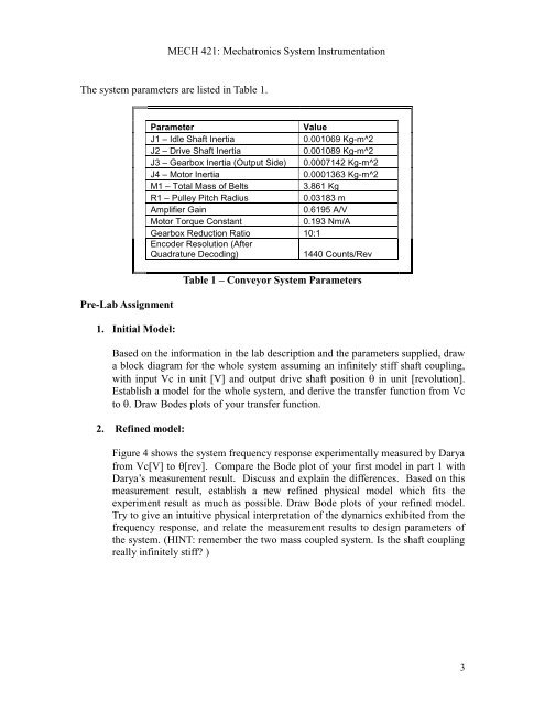
The system parameters are listed in Table 1.<br />
<strong>Pre</strong>-Lab Assignment<br />
1. Initial Model:<br />
Parameter<br />
Value<br />
J1 – Idle Shaft Inertia<br />
0.001069 Kg-m^2<br />
J2 – Drive Shaft Inertia<br />
0.001089 Kg-m^2<br />
J3 – Gearbox Inertia (Output Side) 0.0007142 Kg-m^2<br />
J4 – Motor Inertia<br />
0.0001363 Kg-m^2<br />
M1 – Total Mass of Belts<br />
3.861 Kg<br />
R1 – Pulley Pitch Radius<br />
0.03183 m<br />
Amplifier Gain<br />
0.6195 A/V<br />
Motor Torque Constant<br />
0.193 Nm/A<br />
Gearbox Reduction Ratio 10:1<br />
Encoder Resolution (After<br />
Quadrature Decoding)<br />
1440 Counts/Rev<br />
Table 1 – Conveyor System Parameters<br />
Based on the information in the <strong>lab</strong> description and the parameters supplied, draw<br />
a block diagram for the whole system assuming an infinitely stiff shaft coupling,<br />
with input Vc in unit [V] and output drive shaft position in unit [revolution].<br />
Establish a model for the whole system, and derive the transfer function from Vc<br />
to . Draw Bodes plots of your transfer function.<br />
2. Refined model:<br />
Figure 4 shows the system frequency response experimentally measured by Darya<br />
from Vc[V] to [rev]. Compare the Bode plot of your first model in part 1 with<br />
Darya’s measurement result. Discuss and explain the differences. Based on this<br />
measurement result, establish a new refined physical model which fits the<br />
experiment result as much as possible. Draw Bode plots of your refined model.<br />
Try to give an intuitive physical interpretation of the dynamics exhibited from the<br />
frequency response, and relate the measurement results to design parameters of<br />
the system. (HINT: remember the two mass coupled system. Is the shaft coupling<br />
really infinitely stiff? )<br />
3