REFERENCE 500s 700s 1000s - Soundstream
REFERENCE 500s 700s 1000s - Soundstream
REFERENCE 500s 700s 1000s - Soundstream

Create successful ePaper yourself
Turn your PDF publications into a flip-book with our unique Google optimized e-Paper software.
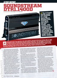
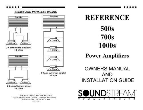
SERIES AND PARALLEL WIRING<br />
<strong>REFERENCE</strong><br />
<strong>500s</strong><br />
<strong>700s</strong><br />
2-4 ohm drivers in parallel<br />
= 2 ohms<br />
<strong>1000s</strong><br />
Power Amplifiers<br />
4-4 ohm drivers in parallel<br />
=1 ohm<br />
OWNERS MANUAL<br />
AND<br />
INSTALLATION GUIDE<br />
2-4 ohm drivers in series<br />
= 8 ohms<br />
SOUNDSTREAM TECHNOLOGIES<br />
120 Blue Ravine Road Folsom California 95630 USA<br />
ph 916.351.1288 fax 916.351.0 414<br />
rev C - 5.01.96<br />
24<br />
1
CONGRATULATIONS!<br />
You now own the <strong>REFERENCE</strong> Amplifier, the product of an<br />
uncompromising design and engineering philosophy. Your<br />
<strong>Soundstream</strong> <strong>REFERENCE</strong> amplifier will outperform any other<br />
amplifier in the world.<br />
To maximize the performance of your system, we recommend that you<br />
thoroughly acquaint yourself with its capabilities and features. Please<br />
retain this manual and your sales and installation receipts for future<br />
reference.<br />
<strong>Soundstream</strong> amplifiers are the result of American craftsmanship and<br />
the highest quality control standards, and when properly installed, will<br />
provide you with many years of listening pleasure. Should your<br />
amplifier ever need service or replacement due to theft, please record<br />
the following information, which will help protect your investment.<br />
Model and Serial # ____________________________________<br />
POWER<br />
SPECIFICATIONS<br />
THD 100 dB<br />
1 Ω Stereo<br />
(2 Ω Bridged)<br />
<strong>REFERENCE</strong><strong>500s</strong><br />
150 x 2<br />
(300 x 1)<br />
250 x 2<br />
(500 x 1)<br />
<strong>REFERENCE</strong><strong>700s</strong><br />
250 x 2<br />
(500 x 1)<br />
350 x 2<br />
(700 x 1)<br />
<strong>REFERENCE</strong><strong>1000s</strong><br />
400 x 2<br />
(800 x 1)<br />
500 x 2<br />
(1000 x 1)<br />
1/2 Ω Stereo<br />
(1 Ω Bridged)<br />
250 x 2<br />
(500 x 1)<br />
350 x 2<br />
(700 x 1)<br />
500 x 2<br />
(1000 x 1)<br />
Dealer’s Name _______________________________________<br />
Date of Purchase _____________________________________<br />
Frequency Response<br />
Stereo Separation<br />
20 Hz to 20 kHz ± 0.5 dB<br />
>90 dB<br />
Installation Shop ______________________________________<br />
Installation Date ______________________________________<br />
Damping >200<br />
Input Sensitivity 200mV - 2.0V, or 500mV to 5.0V<br />
Input Impedance<br />
10K ohms<br />
Crossover Specifications<br />
Low Pass: 45 - 180 Hz at 12 dB/Octave<br />
High Pass: 45 - 180 Hz at 12 dB/Octave<br />
CAUTION!<br />
Prolonged listening at high levels may result in hearing loss. Even<br />
though your new <strong>Soundstream</strong> <strong>REFERENCE</strong> amplifier sounds better<br />
than anything you’ve ever heard, exercise caution to prevent hearing<br />
damage.<br />
2<br />
LSE.Q (<strong>REFERENCE</strong><strong>1000s</strong>)<br />
0.7 - 2.8 Q (0 TO +9 dB), adjustment from 30 to 60 Hz<br />
Dimensions (W x D x H)<br />
<strong>REFERENCE</strong><strong>500s</strong>: 11.0” x 9.8” x 2.25”<br />
<strong>REFERENCE</strong><strong>700s</strong>: 12.25” x 9.8” x 2.25”<br />
23<br />
<strong>REFERENCE</strong><strong>1000s</strong>: 16.0” x 9.8” x 2.25”
PROBLEM<br />
TROUBLESHOOTING<br />
CAUSE<br />
TABLE OF CONTENTS<br />
No sound and power LED is not lit<br />
No sound, a power LED is lit, and<br />
the AIRBASS option has not<br />
been added.<br />
Fault LED is lit<br />
Repeatedly blown amp fuse, frequent<br />
activation of Smart Power<br />
Supply Circuit<br />
Not enough input sensitivity while<br />
using the Balanced input<br />
Left and Right Input Overload indicators<br />
lighting<br />
Alternator whine while using Unbalanced<br />
RCA inputs<br />
• No power or ground at amp<br />
• No remote turn-on signal<br />
• Blown fuse near battery<br />
• No signal input<br />
• The AIRBASS switch is in the<br />
"IN" position. Move it to the<br />
"OUT" position<br />
• Amp power supply fuse is blown<br />
or missing<br />
• Speaker or leads may be shorted<br />
• Verify adequate amplifier ventilation<br />
• Be sure both Left and Right Input<br />
Signal Switches are set to the<br />
"BAL" position<br />
• Input signal level is too high - readjust<br />
input gains, or select the<br />
0.5-5V input signal level range<br />
• Make sure the Right Input Signal<br />
Switch is in the "UNBAL" position.<br />
• Try the Left Input Signal Switch<br />
in the "BAL" and "UNBAL" position:<br />
leave the switch in the quietest<br />
position. This will not effect<br />
the performance of the amplifier.<br />
Design Features ................................................................. 4 - 5<br />
Reference<strong>500s</strong> Diagram .................................................... 6 - 7<br />
Reference<strong>700s</strong> Diagram .................................................... 8 - 9<br />
Reference<strong>1000s</strong> Diagram .............................................. 10 - 11<br />
High Power / Auto High Current Power Supply Design ..... 12<br />
Protection Circuitry ................................................................ 12<br />
Crossover Adjustments ......................................................... 13<br />
AIRBASS ........................................................................... 13<br />
LSE.Q Theory and Use .................................................. 14 - 15<br />
Selecting Input Modes ........................................................... 16<br />
Balanced / Unbalanced Input ................................................ 17<br />
Wiring & Wiring Diagram ................................................ 18 - 19<br />
Installation and Mounting ...................................................... 20<br />
Level Setting ......................................................................... 21<br />
Troubleshooting .................................................................... 22<br />
SERVICE<br />
Your <strong>Soundstream</strong> <strong>REFERENCE</strong> amplifier is protected by a limited warranty.<br />
Service .................................................................................. 22<br />
Specifications ................................................................ ....... 23<br />
22<br />
3
INSTALLATION STEP 5<br />
DESIGN FEATURES<br />
• Uncompromising Design and Construction including mil-spec<br />
glass epoxy circuit boards and high current custom gold-plated solid<br />
brass connections that will accept up to 4 gauge power/ground wire.<br />
• Auto High Current - <strong>Soundstream</strong>’s newest exclusive circuit which<br />
automatically customizes your amplifier to its particular application—<br />
High Current, low impedance loads (multiple subwoofers, less than 2<br />
ohms mono) or High Power, higher impedance loads (2 ohms mono<br />
and up).<br />
• Coherent Stereo TM /Mixed Mono selection for either “pure” stereo<br />
operation or mixed mono for simultaneous stereo and mono.<br />
• Chassisink TM Darlington Power Array - <strong>Soundstream</strong>’s<br />
“overbuilding” of the output section incorporates multiple output<br />
transistors instead of a few for faster, stronger power delivery. The<br />
transistors are sandwiched between the circuit board and the heatsink<br />
in a design called Chassisink TM to ensure cool, efficient amplifier<br />
operation.<br />
• PowerGrid Power Supply Design - All power supply components<br />
are located near one another, connected by thick, wide PCB traces,<br />
which ensures rapid, high current delivery. The entire power supply is<br />
isolated on one side of the circuit board while the audio stage is<br />
located opposite it, guaranteeing minimal noise.<br />
• Ultra-Low ESR Capacitance Bank - Multiple small input power<br />
capacitors are used to provide a lower ESR (Equivalent Series<br />
Resistance), which means more power in and out faster.<br />
• Smart Thermal Rollback - Most amplifiers shut off when they get too<br />
hot. In the unlikely event the <strong>REFERENCE</strong> amplifier reaches 85° C,<br />
it will gradually roll back its average power (without affecting the<br />
dynamics). Once the amplifier has cooled off, it returns to full power<br />
output. If overheating should continue, a second thermal sensing<br />
protection circuit will shut off the amplifier if the heatsink reaches 95°<br />
C.<br />
• Fault Monitor LED on the top panel notifies you of blown power<br />
supply fuses.<br />
• 1/2 ohm Drive Ability - The <strong>REFERENCE</strong> amplifiers are designed to<br />
LEVEL SETTING<br />
The input levels are adjusted by means of the individual channel input level<br />
controls located on the front of the amplifier. This is a unique dual-stage<br />
circuit that adjusts both level and gain. This topology maintains better Signal<br />
to Noise ratios even when using sources with minimal output.<br />
In the ideal situation, all components in the audio system reach maximum<br />
undistorted output at the same time. The reason is because an amplifier will<br />
only make what comes into it bigger. So, if you send it a distorted signal from<br />
the head unit, the amplifier is going to amplify distorted information. The<br />
same thing holds true if an outboard processor or crossover begins to distort<br />
before you have maximum output from the amplifier. By setting all<br />
components to reach clipping at the same time, you can maximize the output<br />
of your system. For the <strong>REFERENCE</strong> amplifiers, follow the following steps for<br />
the quickest, easiest means of setting the levels.<br />
1. Turn the amp’s input levels to minimum position (fully counterclockwise).<br />
2. Begin with the input level switch in the 0.5 - 5.0 Volt position.<br />
3. Set source unit volume to approximately 3/4 of full volume.<br />
4. While playing dynamic source material, slowly increase the amplifier’s<br />
input level until a near maximum undistorted level is heard in the<br />
system.<br />
If your preamplifier / source unit has an extremely high output level, be sure to<br />
pay attention to the clipping indicators located on the top of the amplifier.<br />
These indicators will notify you if you are clipping the PREAMPLIFIER stage of<br />
the amplifier. If the amplifier's output is distorted and the clipping lights are<br />
not blinking, you are most likely clipping the OUTPUTS of the amplifier, or<br />
driving the speaker to distortion.<br />
4<br />
21
INSTALLATION STEP 4<br />
INSTALLATION AND MOUNTING<br />
1. AMPLIFIER LOCATION<br />
The <strong>REFERENCE</strong> amplifiers employ highly efficient circuitry and a unique<br />
Chassisink TM design to maintain lower operating temperatures. Additional<br />
cooling may be required if the amplifier is located in a tightly confined area or<br />
when driving especially low impedance loads at extremely high levels.<br />
When mounting the amplifier, it should be securely mounted to either a panel<br />
in the vehicle or an amp board or rack that is securely mounted to the vehicle.<br />
The mounting location should be either in the passenger compartment or in the<br />
trunk of the vehicle, away from moisture, stray or moving objects, and major<br />
electrical components. To provide adequate ventilation, mount the amplifier so<br />
that there are at least two inches of freely circulating air above and to the sides<br />
of it.<br />
2. SWITCHES<br />
Set the Coherent Stereo TM /Mixed-Mono/Bridged Mono and Amplifier crossover<br />
switches on the bottom of the amplifier to the appropriate positions before<br />
bolting down the amplifier (see pages 13 - 16). Be sure to replace the hole<br />
plugs.<br />
3. MOUNTING THE AMPLIFIER<br />
a. Using the amplifier as a template, mark the mounting surface.<br />
b. Remove the amplifier and drill the holes.<br />
c. Mount the amplifier to the surface using the provided hardware.<br />
4. WIRING<br />
a. Run and connect the audio signal and remote turn-on cables to the<br />
amplifier from the source unit.<br />
b. Carefully run the positive cable from the amplifier to a fuse or circuit<br />
breaker within 18” of the battery.<br />
c. Connect the fuse or circuit breaker to the battery. Leave the circuit breaker<br />
off or the fuse out until everything is bolted down.<br />
d. Secure the ground cable to a solid chassis ground on the vehicle. It may<br />
drive virtually any load—all the way down to 1/2 ohm stereo (1 ohm<br />
mono).<br />
• Dual Discrete Class A Drive Stages - Over six times the drive<br />
current of most amplifiers in the Reference<strong>500s</strong> and <strong>700s</strong>, and over<br />
twelve times in the Reference<strong>1000s</strong>! More drive current maintains<br />
the amplifiers' performance into low impedance loads.<br />
• Drive Delay TM Muted Turn-on/off Circuit - A unique circuit which<br />
completely eliminates any amplifier-related turn-on/off noises.<br />
• Flexible Dual Input Level Sensitivity accepts 2 voltage ranges;<br />
from 200 mV to 2.0 V and from 500 mV to 5.0 V, permitting<br />
maximum output from the amplifier with virtually any source unit.<br />
• Differential Balanced Input Design for added immunity to noise<br />
caused by component and vehicle electrical system interaction when<br />
using Unbalanced RCA inputs.<br />
• True Balanced Input for professional-quality performance and noise<br />
cancellation. The 6-pin din plug carries (+) and (-) Signal information<br />
for Left and Right channels, audio ground, and ±15 Vdc to operate<br />
the <strong>Soundstream</strong> BLT Balanced Line Transmitter.<br />
• AIRBASS Upgradable - This feature allows RF remote control<br />
level adjustment while the low pass filter on the amplifiers' internal<br />
crossover is being used.<br />
• LSE.Q (Reference<strong>1000s</strong>) - Fully adjustable subwoofer equalization<br />
circuit providing frequency and level "Q" adjustment for optimum<br />
subwoofer performance. A frequency tracking subsonic filter protects<br />
woofers from potentially harmful low frequency information and<br />
maximizes output in a usable range.<br />
NOTE: There may be a sizable spark when connecting the power and ground<br />
lead to the amplifier for the first time. Please see the comment on the previous<br />
be necessary to sand paint down to raw metal for a good connection.<br />
e. Double check each and every connection!<br />
f. Re-connect the fuse or circuit breaker.<br />
20<br />
5
Reference<strong>500s</strong><br />
(Continued from page 18)<br />
below to determine the fuse value. Never replace the fuses with a higher<br />
value than what is supplied. This may result in amplifier damage and will<br />
void the warranty!<br />
<strong>REFERENCE</strong> Amplifier Fuse Values<br />
Amplifier Amplifier Fuse Battery Fuse /<br />
Circuit Breaker<br />
<strong>REFERENCE</strong><strong>500s</strong> (2) 20 amp automotive 50 amp<br />
<strong>REFERENCE</strong><strong>700s</strong> 60 amp Maxi-Fuse 80 amp<br />
<strong>REFERENCE</strong><strong>1000s</strong> 80 amp Maxi-Fuse 100 amp<br />
REMOTE TURN-ON<br />
Connect the “Remote” to the turn-on lead from the source unit. When +12<br />
volts is received, the amplifier will turn on.<br />
SIGNAL CABLE<br />
Use a high-quality cable that will be easy to install and has minimal signal loss<br />
to guarantee optimum performance. <strong>Soundstream</strong>’s DL1 and SL1 are<br />
ideal when using the Unbalanced RCA inputs. While using the Balanced DIN<br />
input, use the cable supplied with the BLT.<br />
SPEAKER CABLE<br />
The <strong>REFERENCE</strong> amps will accept up to 8 gauge speaker cable. Use a high<br />
quality, flexible, multi-strand cable for best performance and longevity.<br />
WIRING DIAGRAM<br />
6<br />
19
INSTALLATION STEP 3<br />
WIRING<br />
POWER AND GROUND<br />
To ensure maximum output from your <strong>REFERENCE</strong> amplifier, use high<br />
quality, low-loss power and ground cables. The <strong>REFERENCE</strong> amplifiers will<br />
accept up to 4 gauge power and ground cables. Determine from the chart<br />
<strong>REFERENCE</strong><strong>500s</strong><br />
<strong>REFERENCE</strong><strong>700s</strong><br />
up to 10’ up to 20’<br />
<strong>Soundstream</strong> Power40 or<br />
Power80<br />
<strong>Soundstream</strong> Power40 or<br />
Power80<br />
18<br />
<strong>Soundstream</strong> Power40 only<br />
(4 ga.)<br />
<strong>Soundstream</strong> Power40 only<br />
(4 ga.)<br />
<strong>REFERENCE</strong><strong>1000s</strong> <strong>Soundstream</strong> Power40 only <strong>Soundstream</strong> Power40 only<br />
Read this, or sparks will fly!<br />
The <strong>Soundstream</strong> <strong>REFERENCE</strong> amplifiers have extensive internal power<br />
supply capacitance, called the Ultra-Low ESR Capacitance Bank. Multiple<br />
small input power capacitors act as an internal "stiffening capacitor". Because<br />
of the large amount of internal capacitance, there may be a sizable spark<br />
when connecting the power and ground lead to the amplifier for the first time.<br />
In order to charge the capacitor bank without a spark, we suggest you do the<br />
following:<br />
1. Connect the +12 volt cable to the amplifier and to the battery.<br />
2. Connect one end of the ground cable to the chassis of the vehicle.<br />
3. We have supplied a 150 ohm, 2 watt resistor with the amplifier. One leg<br />
of the resistor has been connected to the ground terminal of the amplifier.<br />
4. To charge the capacitor bank, touch the loose end of the ground cable to<br />
CIRCUIT BREAKERS/FUSES<br />
EXTERNAL<br />
Like all audio components, the <strong>REFERENCE</strong> amplifiers must be fused near<br />
the battery. A fuse or circuit breaker must be located within 18” of the battery.<br />
This will prevent a fire in the event of a shorted cable. See the chart below to<br />
determine the correct fuse value.<br />
INTERNAL<br />
The <strong>REFERENCE</strong> amplifiers are fused with either automotive-type or Maxifuses.<br />
In the event of blown power supply fuse(s), the “Fault” indicator on the<br />
top panel will light. The fuses are accessible either from the front panel of the<br />
amplifier or via a plastic plug on the bottom of the amplifier. See the chart<br />
(Continued on page 19)<br />
Key to Callouts<br />
1. Fault LED - Indicates a blown fuse.<br />
2. High Power LED - Indicates amplifier power on in "High Power" mode.<br />
3. Auto High Current LED - Indicates amplifier power on in "High Current"<br />
mode.<br />
4. Line Out Crossover Switch - Select high pass, low pass or full range low<br />
level output to an auxiliary amplifier.<br />
5. Input Overload Indicators - Indicates the signal input level or input gain<br />
level is too high.<br />
6. Input Level Selector Switch - Selectable input sensitivity range from 0.2-<br />
2 Volts RMS, or from 0.5-5 Volts RMS.<br />
7. Left Channel Balanced / Unbalanced Input Selector Switch - Select<br />
"Balanced" to use the 6 pin Balanced signal input. Select "Unbalanced" to<br />
use the RCA signal inputs.<br />
8. Right Channel Balanced / Unbalanced Input Selector Switch - Select<br />
"Balanced" to use the 6 pin Balanced signal input. Select "Unbalanced" to<br />
use the RCA signal inputs.<br />
9. +12V - Connected to a fuse or circuit breaker, then to the battery's positive<br />
post.<br />
10. GND - Main ground connection. Bolt to a clean chassis ground in the<br />
vehicle.<br />
11. REM - Remote turn-on input from the head unit. Accepts +12V.<br />
12. Speaker Output Connections - Left and right channels.<br />
13. Crossover Output - High pass, low pass or full range output to an<br />
auxiliary amplifier.<br />
14. Crossover Adjustment Pots - Crossover frequency settings for high<br />
pass and low pass filters; Amplifier and crossover outputs.<br />
15. Input Level - Independent Left and Right channel input level controls.<br />
16. Balanced Signal Input Connector - 6-pin Balanced signal input<br />
connector for use with the <strong>Soundstream</strong> BLT Balanced Line Transmitter.<br />
17. Inputs - Right and left channel RCA (Unbalanced ) inputs; only right<br />
channel input is used in "Mono" mode.<br />
18. Main Fuse - Main power supply fuse. Replace only with the same value<br />
fuse.<br />
19. Coherent Stereo/Bridge/Mixed Mono switch - Select "Bridge" for<br />
bridged mono operation (use right channel input). Select "Stereo" for<br />
coherent stereo operation. Select "Mixed Mono" for simultaneous stereo /<br />
bridged mono operation.<br />
20. Amplifier Crossover - Select high pass, low pass or full range amplifier<br />
operation.<br />
7
Reference<strong>700s</strong><br />
INSTALLATION STEP 2<br />
BALANCED / UNBALANCED INPUT<br />
The <strong>REFERENCE</strong> amplifiers have the ability to accept either a standard<br />
Unbalanced RCA signal inputs, or a Balanced "Pro Audio" inputs with the use<br />
of the <strong>Soundstream</strong> BLT Balanced Line Transmitter or some other balanced<br />
line audio source. Before installing your system, you should decide upon<br />
ADVANTAGES<br />
UNBALANCED INPUT<br />
1. Most preamplifier / source<br />
units have "UNBAL" RCA<br />
outputs. (Industry standard)<br />
2. No Interface module is necessary<br />
BALANCED INPUT<br />
1. Improved Signal to Noise<br />
Ratio. (S/N Ratio)<br />
2. Excellent noise cancellation<br />
characteristics.<br />
3. Immune to noise radiated in<br />
the car audio environment.<br />
The <strong>REFERENCE</strong> amplifiers' signal inputs accept two ranges of input signal<br />
levels: 0.2 - 2.0 Vrms, or 0.5 - 5.0 Vrms for both Balanced and Unbalanced<br />
inputs. The input range switch position and level settings are dependent upon<br />
the preamplifier / source unit output signal level. For the best system Signal to<br />
Noise Ratio, we recommend that the input level controls be set as far down as<br />
possible (rotated counter-clockwise), while maintaining an acceptable level of<br />
output.<br />
Using the "Unbalanced" RCA input<br />
When using the Unbalanced RCA input, the RIGHT channel input signal<br />
switch MUST be in the "UNBAL" position. Also, when first installing the<br />
amplifier using this input configuration, we suggest that the left channel input<br />
signal switch be in the "UNBAL" position as well. If you experience<br />
alternator wine or other installation noise with both switches in the<br />
"UNBAL" position, try moving the LEFT channel input signal switch to<br />
the "BAL" position. This should remove any system noise due to<br />
installation.<br />
Using the "Balanced" RCA input<br />
When using the Balanced 6-pin DIN input, both switches MUST be in the<br />
"BAL" position. Also, we recommend that when using this input configuration,<br />
the "INPUT LEVEL" switch be in the "0.5 - 5V" position, and the gains on the<br />
8<br />
NOTE: The pin<br />
configuration shown<br />
in the diagram is the<br />
view looking into the<br />
Balanced input jack<br />
on the amplifier.<br />
17
INSTALLATION STEP 1<br />
COHERENT STEREO /<br />
MIXED-MONO / BRIDGED MONO<br />
The <strong>REFERENCE</strong> amplifiers have the ability to operate in any one of the<br />
following modes:<br />
Coherent Stereo with identical left and right stereo channels for<br />
maximum fidelity. Best choice for satellite speakers. Use this mode unless<br />
Mixed-Mono is necessary.<br />
Mixed-Mono in order to drive stereo and mono simultaneously; works well<br />
for center channels. It can be used anytime you need a summed mono<br />
channel. Somewhat sacrifices sonic accuracy as additional circuitry is<br />
introduced to one channel. In Mixed-Mono, the left channel is inverted, see<br />
diagram below or on the bottom of the amplifier.<br />
Bridged Mono for dedicated single channel operation; ideal for driving<br />
subwoofers. It is also used when large amounts of power are necessary for<br />
single speakers. In bridged mono, only the right channel input is active.<br />
In bridged mono, only the right channel input is active.<br />
NOTE: If you intend to drive a<br />
<strong>REFERENCE</strong> amp in Mono but have stereo<br />
outputs from your crossover or source unit,<br />
you can put the switch in Mixed-Mono but<br />
follow the normal wiring for Bridged Mono.<br />
Key to Callouts<br />
1. Fault LED - Indicates a blown fuse.<br />
2. High Power LED - Indicates amplifier power on in "High Power" mode.<br />
3. Auto High Current LED - Indicates amplifier power on in "High Current"<br />
mode.<br />
4. Line Out Crossover Switch - Select high pass, low pass or full range low<br />
level output to an auxiliary amplifier.<br />
5. Input Overload Indicators - Indicates the signal input level or input gain<br />
level is too high.<br />
6. Input Level Selector Switch - Selectable input sensitivity range from 0.2-<br />
2 Volts RMS, or from 0.5-5 Volts RMS.<br />
7. Left Channel Balanced / Unbalanced Input Selector Switch - Select<br />
"Balanced" to use the 6 pin Balanced signal input. Select "Unbalanced" to<br />
use the RCA signal inputs.<br />
8. Right Channel Balanced / Unbalanced Input Selector Switch - Select<br />
"Balanced" to use the 6 pin Balanced signal input. Select "Unbalanced" to<br />
use the RCA signal inputs.<br />
9. Main Fuse - Main power supply fuse. Replace only with the same value<br />
fuse.<br />
10. +12V - Connected to a fuse or circuit breaker, then to the battery's positive<br />
post.<br />
11. GND - Main ground connection. Bolt to a clean chassis ground in the<br />
vehicle.<br />
12. REM - Remote turn-on input from the head unit. Accepts +12V.<br />
13. Speaker Output Connections - Left and right channels.<br />
14. Crossover Output - High pass, low pass or full range output to an<br />
auxiliary amplifier.<br />
15. Crossover Adjustment Pots - Crossover frequency settings for high<br />
pass and low pass filters; Amplifier and crossover outputs.<br />
16. Input Level - Independent Left and Right channel input level controls.<br />
17. Balanced Signal Input Connector - 6-pin Balanced signal input<br />
connector for use with the <strong>Soundstream</strong> BLT Balanced Line Transmitter.<br />
18. Inputs - Right and left channel RCA (Unbalanced ) inputs; only right<br />
channel input is used in "Mono" mode.<br />
19. Coherent Stereo/Bridge/Mixed Mono switch - Select "Bridge" for<br />
bridged mono operation (use right channel input). Select "Stereo" for<br />
coherent stereo operation. Select "Mixed Mono" for simultaneous stereo /<br />
bridged mono operation.<br />
20. Amplifier Crossover - Select high pass, low pass or full range amplifier<br />
operation.<br />
16<br />
9
Reference<strong>1000s</strong><br />
LSE.Q THEORY AND USE (continued)<br />
8.0<br />
frequencies below resonance, the<br />
7.0<br />
woofer starts to behave as if it were 6.0<br />
5.0<br />
mounted in “free-air”. If we wish to Xd<br />
(mM) 4.0<br />
improve the performance of a<br />
3.0<br />
vented system, we should remove 2.0<br />
1.0<br />
these unwanted signals from our<br />
0.0<br />
10 Frequency (Hz) 50 100 200<br />
system. These can be removed by<br />
adding a subsonic filter. Figure 5 FIG. 5 Limited Excursion<br />
shows the effectiveness of LSE.Q on<br />
woofer excursion. Woofer travel is 7.5 mm at 10 Hz, with LSE.Q<br />
properly adjusted, this excursion can be reduced to less than 1 mm.<br />
This is of great benefit to lowering woofer<br />
distortion and increasing output.<br />
Adjustment<br />
An easy method of optimizing your existing<br />
subwoofer enclosure with LSE.Q's “Hz” control<br />
is as follows.<br />
1 Adjust frequency and boost control to full<br />
CCW position. (See figure 6)<br />
2 While listening to music with strong bass<br />
content at a moderate level, slowly adjust<br />
frequency control clockwise. Listen for a reduction of bass response.<br />
Now, rotate frequency control slightly backwards. This serves the<br />
purpose of removing the “subsonic”<br />
10<br />
5<br />
0<br />
-5<br />
dB<br />
-10<br />
-15<br />
-20<br />
-25<br />
-30 10<br />
Frequency (Hz)<br />
50 100 200<br />
FIG. 7 Various Settings<br />
FIG. 6 LSE.Q Setting<br />
bass energy.<br />
<strong>Soundstream</strong>’s LSE.Q contains the<br />
same type of circuit with the added<br />
benefit of infinite adjustability. Our<br />
“Q” and “Hz” control can provide<br />
virtually any combination of boost<br />
and cut to suit your designs. So,<br />
LSE.Q can provide the “tailoring”<br />
needed for any type of “assisted”<br />
NOTE: The LSE.Q circuit on the REF<strong>1000s</strong> can be defeated for flat<br />
operation down to 20 Hz by placing the LSE.Q switch in the "OUT"<br />
position. You may wish to use this option to achieve a higher S/N Ratio<br />
when using ultra-high efficiency speakers, such as compression<br />
10<br />
15
LSE.Q THEORY AND USE (Reference<strong>1000s</strong>)<br />
FIG. 1 LSE.Q<br />
LSE.Q is a unique subwoofer control circuit<br />
included with the SOUNDSTREAM<br />
<strong>REFERENCE</strong><strong>1000s</strong> amplifier. It is capable of<br />
removing subsonic energy in program material.<br />
The circuit consists of two controls. One adjusts<br />
the frequency of operation and the other adjusts<br />
the range of boost. With both controls adjusted<br />
fully counter-clockwise, no boost is applied and<br />
the amplifier is flat in response down to 30 Hz.<br />
The frequency control (Hz) adjusts the starting point of the subsonic<br />
filter. This high pass filter can be adjusted from 30 Hz up to a<br />
maximum of 60 Hz. This control<br />
is useful for setting the lowest<br />
frequency that your subwoofer will<br />
10<br />
5<br />
0<br />
Q=2.8<br />
-5<br />
see. (See figure 1)<br />
dB<br />
The Q control adjusts the<br />
amount of boost applied at the set<br />
frequency. This is adjustable<br />
from .707 (flat) to 2.8 (+9 dB).<br />
(See figure 2)<br />
When the Q is set to .707<br />
(Butterworth), LSE.Q acts as a<br />
sub-sonic filter only. (See figure<br />
3)<br />
-5<br />
dB<br />
-10<br />
The simple act of removing the -20<br />
signal below the vented tuning<br />
-25<br />
-30<br />
frequency can improve system 10<br />
output by as much as 3 dB. With<br />
Q values greater than .707, boost<br />
is added to the sub-sonic filter. (see figure 4)<br />
10<br />
5<br />
0<br />
-5<br />
dB<br />
-10<br />
-15<br />
-20<br />
-25<br />
-30 10<br />
Frequency (Hz)<br />
FIG. 4 Variable “Q”<br />
50 100 200<br />
14<br />
-10<br />
-15<br />
-20<br />
-25<br />
-30 10<br />
10<br />
5<br />
0<br />
-15<br />
Frequency (Hz)<br />
FIG. 2 Variable “Q”<br />
Frequency (Hz)<br />
Q=0.707<br />
50 100 200<br />
50 100 200<br />
FIG. 3 Variable High Pass<br />
Application<br />
Woofers in vented enclosures have<br />
good power handling characteristics<br />
above the tuning frequency, but<br />
below the tuning frequency, power<br />
handling drops off considerably.<br />
This is due to the loss of any<br />
appreciable resistive air mass. At<br />
Key to Callouts<br />
1. Fault LED - Indicates a blown fuse.<br />
2. High Power LED - Indicates amplifier power on in "High Power" mode.<br />
3. Auto High Current LED - Indicates amplifier power on in "High Current"<br />
mode.<br />
4. Line Out Crossover Switch - Select high pass, low pass or full range low<br />
level output to an auxiliary amplifier.<br />
5. LSE.Q Bypass Switch - Turns the LSE.Q on ("IN") or off ("OUT").<br />
6. Input Overload Indicators - Indicates the signal input level or input gain<br />
level is too high.<br />
7. Input Level Selector Switch - Selectable input sensitivity range from 0.2-<br />
2 Volts RMS, or from 0.5-5 Volts RMS.<br />
8. Left Channel Balanced / Unbalanced Input Selector Switch - Select<br />
"Balanced" to use the 6 pin Balanced signal input. Select "Unbalanced" to<br />
use the RCA signal inputs.<br />
9. Right Channel Balanced / Unbalanced Input Selector Switch - Select<br />
"Balanced" to use the 6 pin Balanced signal input. Select "Unbalanced" to<br />
use the RCA signal inputs.<br />
10. Main Fuse - Main power supply fuse. Replace only with the same value<br />
fuse.<br />
11. +12V - Connected to a fuse or circuit breaker, then to the battery's positive<br />
post.<br />
12. GND - Main ground connection. Bolt to a clean chassis ground in the<br />
vehicle.<br />
13. REM - Remote turn-on input from the head unit. Accepts +12V.<br />
14. Speaker Output Connections - Left and right channels.<br />
15. Crossover Output - High pass, low pass or full range output to an<br />
auxiliary amplifier.<br />
16. Crossover Adjustment Pots - Crossover frequency settings for high<br />
pass and low pass filters; Amplifier and crossover outputs.<br />
17. LSE.Q - Frequency and Q adjustments.<br />
18. Input Level - Independent Left and Right channel input level controls.<br />
19. Balanced Signal Input Connector - 6-pin Balanced signal input<br />
connector for use with the <strong>Soundstream</strong> BLT Balanced Line Transmitter.<br />
20. Inputs - Right and left channel RCA (Unbalanced ) inputs; only right<br />
channel input is used in "Mono" mode.<br />
21. Coherent Stereo/Bridge/Mixed Mono switch - Select "Bridge" for<br />
bridged mono operation (use right channel input). Select "Stereo" for<br />
coherent stereo operation. Select "Mixed Mono" for simultaneous stereo /<br />
bridged mono operation.<br />
22. Amplifier Crossover - Select high pass, low pass or full range amplifier<br />
operation.<br />
11
AUTO HIGH CURRENT POWER SUPPLY<br />
The <strong>REFERENCE</strong><strong>500s</strong>/<strong>700s</strong>/<strong>1000s</strong> amplifiers employ an extremely efficient<br />
Auto High Current power supply (patent pending). This new power supply<br />
circuitry automatically customizes your amplifier for optimum efficiency and<br />
power output into virtually any impedance load. When other brand amplifiers<br />
are driven at low impedances (i.e., 1 ohm or less), they shut down, squash<br />
dynamics and power output (called current limiting), or waste huge amounts of<br />
power (i.e., low efficiency). All of which reduce the "realworld" power the<br />
amplifier can produce in the car. <strong>Soundstream</strong>'s Auto High Current power<br />
supply allows the <strong>REFERENCE</strong> amplifiers to be one of two types of amps:<br />
either producing maximum power at higher impedances (perfect for satellites)<br />
or at lower impedances (usually with multiple subwoofers). This is done by<br />
letting the amplifiers' power supply continuously monitor the impedance of the<br />
load the amplifier is driving. If the impedance drops too low, the power supply<br />
will automatically switch into High Current mode. It will stay in this mode until<br />
the amplifier is turned off. The next time it is powered up, it will be in the High<br />
Power mode.<br />
Unlike other amplifiers, <strong>Soundstream</strong>’s <strong>REFERENCE</strong> amplifiers can be<br />
configured to drive virtually any impedance and make maximum power! The<br />
major advantages of this power supply are:<br />
• awesome dynamic power capabilities<br />
• added continuous power with higher voltages<br />
• increased amplifier efficiency and reliability<br />
Because of the dynamic properties of most music, all audio components<br />
should be able to react accordingly. Thanks to their unique power supplies,<br />
PROTECTION CIRCUITRY<br />
Your <strong>REFERENCE</strong> amplifier is protected against both overheating and short<br />
circuits by means of the following circuits:<br />
• Main power supply fuses<br />
• Auto High Current power supply<br />
• Smart Power Supply Thermal Rollback activating at 85°C<br />
• A fail-safe thermal protection circuit activating at 95°C<br />
Your amplifier also incorporates an innovative Fault Diagnosis system that<br />
NOTE: If you experience blown main power supply fuses, it is likely that the<br />
amplifier is seeing a dead short, either in the speaker wire or in the speaker<br />
itself. Rectify the problem before blowing multiple fuses! DO NOT increase<br />
values beyond the original fuse value! Doing so will void your warranty and<br />
12<br />
CROSSOVER ADJUSTMENTS<br />
The <strong>REFERENCE</strong> amplifiers incorporate an on-board staggered electronic<br />
crossover, with RCA outputs to drive an external amplifier. No external<br />
electronic crossover is necessary. The high and low pass portions of the<br />
crossover can be set independently of one another.<br />
In most car audio installations, there is a tendency for a “midbass boom.”<br />
Because of their interior dimensions, most cars will resonate or ring at these<br />
midbass frequencies. If we design the system so there is less musical<br />
information in this region, the final response is very smooth and natural<br />
sounding. The high pass and low pass crossovers are independently variable<br />
from 45 to 180 Hz at 12 dB/octave.<br />
For initial crossover setup, try setting the low pass filter to approximately 60<br />
Hz, and the high pass filter to approximately 100 Hz. Change the crossover<br />
points to accommodate a good mixture of frequency response, power<br />
12 dB/Oct. Low Pass<br />
12 dB/Oct. High Pass<br />
NOTE: There is an +8 dB boost in signal level<br />
when the amplifier's internal low pass filter is<br />
engaged. This boost does not apply to the<br />
RCA outputs.<br />
AIRBASS ACCESSORY OPTION<br />
<strong>Soundstream</strong>'s new AIRBASS feature can be added to the <strong>REFERENCE</strong><br />
amplifiers. This feature allows wireless RF remote control level adjustment of<br />
the amplifier, while the low pass filter on the amplifiers' internal crossover is<br />
engaged. (AIRBASS does not control the level of the RCA signal outputs.)<br />
NOTE: The AIRBASS accessory is intended to be used only while the<br />
<strong>REFERENCE</strong> amplifiers are driving subwoofers. When the AIRBASS<br />
accessory is added to a <strong>REFERENCE</strong> amplifier, it automatically configures the<br />
amplifier into Bridged Mono mode. (The Coherent Stereo / Mixed Mono /<br />
Bridged Mono switch is bypassed.) Therefore, when using AIRBASS, follow<br />
the Bridged Mono input and output wiring instructions. (See page 16.)<br />
Installing AIRBASS involves removing the bottom plate of the amplifier,<br />
adding the AIRBASS circuit board, and flipping a switch. The switch is<br />
labeled on the amplifier's main circuit board. DO NOT set the AIRBASS<br />
switch to the "IN" position unless the AIRBASS module has been added.<br />
DO NOT move the AIRBASS switch while the amplifier is "ON". Doing so<br />
may damage your speakers. (Please refer to the AIRBASS owner's /<br />
installation manual for more details.)<br />
13