Developing Responsive and Agile Space Systems - Space-Library
Developing Responsive and Agile Space Systems - Space-Library
Developing Responsive and Agile Space Systems - Space-Library

You also want an ePaper? Increase the reach of your titles
YUMPU automatically turns print PDFs into web optimized ePapers that Google loves.
Crosslink<br />
The Aerospace Corporation magazine of advances aerospace technology ®<br />
Summer 2009<br />
<strong>Developing</strong><br />
<strong>Responsive</strong> <strong>and</strong><br />
<strong>Agile</strong> <strong>Space</strong> <strong>Systems</strong>
Crosslink<br />
Summer 2009 Vol. 10 No. 1<br />
Departments<br />
2 Headlines<br />
4 Profile<br />
Mark A. Hopkins<br />
43 Research Horizons<br />
Low-Power Electric Propulsion<br />
Electric Propulsion<br />
Diagnostics <strong>and</strong> Modeling<br />
45 Bookmarks<br />
50 Contributors<br />
52 The Back Page<br />
The Aerospace Ground<br />
<strong>Systems</strong> Laboratory<br />
In This Issue<br />
6 Creating An <strong>Agile</strong>, All-<strong>Space</strong> Architecture<br />
Thomas Adang <strong>and</strong> James Gee<br />
Aerospace is working with the Operationally<br />
<strong>Responsive</strong> <strong>Space</strong> Office <strong>and</strong> other defense<br />
organizations to develop a comprehensive space<br />
architecture that will meet urgent warfighter needs.<br />
12 Open Architectures <strong>and</strong> St<strong>and</strong>ards<br />
for <strong>Agile</strong> <strong>Space</strong><br />
Douglas Harris<br />
Aerospace is helping to establish open st<strong>and</strong>ards for<br />
space, which can contribute to a more robust <strong>and</strong> rapid<br />
response to urgent warfighter needs.<br />
Crosslink<br />
The Aerospace Corporation magazine of advances aerospace technology ®<br />
Summer 2009<br />
18 <strong>Agile</strong> <strong>Space</strong> Launch<br />
<strong>Developing</strong><br />
<strong>Responsive</strong> <strong>and</strong><br />
<strong>Agile</strong> <strong>Space</strong><br />
<strong>Systems</strong><br />
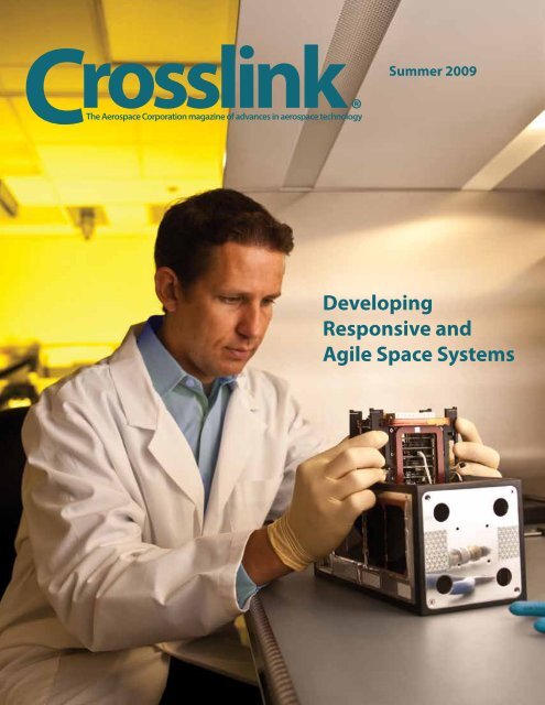
On the cover: Petras Karuza, Mechanics Research<br />
Office, installs the electronics core into the Pico<br />
Satellite Solar Cell Testbed nanosatellite. The core<br />
contains everything the nanosatellite needs: solar<br />
array <strong>and</strong> battery management, flight computer,<br />
inertial measurement unit, radio, camera controller,<br />
<strong>and</strong> an experiment controller.<br />
Copyright © 2009 The Aerospace Corporation. All rights reserved.<br />
Permission to copy or reprint is not required, but appropriate credit<br />
must be given to Crosslink <strong>and</strong> The Aerospace Corporation.<br />
All trademarks, service marks, <strong>and</strong> trade names are the property of<br />
their respective owners.<br />
Crosslink (ISSN 1527-5264) is published by The Aerospace Corporation,<br />
an independent, nonprofit corporation dedicated to providing<br />
objective technical analyses <strong>and</strong> assessments for military, civil, <strong>and</strong><br />
commercial space programs. Founded in 1960, the corporation operates<br />
a federally funded research <strong>and</strong> development center specializing<br />
in space systems architecture, engineering, planning, analysis, <strong>and</strong> research,<br />
predominantly for programs managed by the Air Force <strong>Space</strong><br />
<strong>and</strong> Missile <strong>Systems</strong> Center <strong>and</strong> the National Reconnaissance Office.<br />
For more information about Aerospace, visit www.aero.org or<br />
write to Corporate Communications, P.O. Box 92957, M1-447, Los<br />
Angeles, CA 90009-2957.<br />
Questions about Crosslink may be sent via email to crosslink@aero.<br />
org or write to The Aerospace Press, P.O. Box 92957, Los Angeles, CA<br />
90009-2957. Visit the Crosslink Web site at www.aero.org/publications/<br />
crosslink.<br />
ii • Crosslink Summer 2009<br />
Steven Weis <strong>and</strong> Lisa Berenberg<br />
Aerospace has been providing systems engineering<br />
support to the <strong>Space</strong> Test Program, Operationally<br />
<strong>Responsive</strong> <strong>Space</strong> Office, <strong>and</strong> Air Force Research<br />
Laboratory, in an effort to rapidly launch <strong>and</strong> deploy<br />
satellites in the evolving agile space environment.<br />
24 A Flexible Satellite Comm<strong>and</strong> <strong>and</strong><br />
Control Framework<br />
Thomas Sullivan, Donald Sather, <strong>and</strong><br />
Ronald Nishinaga<br />
A st<strong>and</strong>ard communications infrastructure <strong>and</strong> shared<br />
services allow for rapid receiving <strong>and</strong> publishing of<br />
mission information using common message <strong>and</strong> data<br />
st<strong>and</strong>ards, thus enabling situational awareness along<br />
with reduced operation <strong>and</strong> maintenance costs.
From the Editors<br />
30 <strong>Developing</strong> a <strong>Responsive</strong> Ground<br />
System Enterprise<br />
Rico Espindola <strong>and</strong> Gayla Walden<br />
<strong>Responsive</strong> space requires responsive ground<br />
systems. Aerospace is helping to establish<br />
a comprehensive ground system enterprise<br />
that can meet the anticipated tactical<br />
dem<strong>and</strong>s.<br />
37 Building Miniature <strong>Space</strong>craft at<br />
The Aerospace Corporation<br />
David Hinkley <strong>and</strong> Siegfried Janson<br />
Imagine flying a satellite with a technology<br />
freeze date that was only six months ago.<br />
Aerospace has completed 11 miniature<br />
satellites for technology demonstrations,<br />
with an average design, build, assemble, test,<br />
<strong>and</strong> deliver cycle of about a year.<br />
The term “agile space” stems from a growing consensus within the<br />
space community that the United States must be able to field certain<br />
classes of space systems more rapidly <strong>and</strong> flexibly. To help realize<br />
this goal, the DOD established the Operationally <strong>Responsive</strong> <strong>Space</strong><br />
(ORS) Office in May 2007; its goal is to identify <strong>and</strong> address technological<br />
issues that will enable a more timely delivery of spacebased<br />
services to meet warfighter needs.<br />
The ORS Office has devised an end-state architecture <strong>and</strong> is identifying<br />
the technologies that will enable its realization. Aerospace has<br />
been contributing to the definition <strong>and</strong> execution of this architecture,<br />
which encompasses all aspects of space systems—launch, space,<br />
<strong>and</strong> ground. Articles in this issue of Crosslink review the various<br />
components of this architecture <strong>and</strong> the progress that has been<br />
made toward implementing <strong>and</strong> coordinating them.<br />
It is important to note that the ORS Office is not in competition with<br />
major space programs; rather, it is an adjunct to those programs<br />
<strong>and</strong> the systems they support. Its immediate focus is on the application<br />
of space power to the tactical theater. That includes devising<br />
new concepts for developing <strong>and</strong> deploying satellites, but it also entails<br />
exploiting existing space systems <strong>and</strong> infrastructure to achieve<br />
tactical dem<strong>and</strong>s with greater speed <strong>and</strong> versatility.<br />
The ORS Office is not the only—nor the first—organization to pursue<br />
agile space concepts. The DOD’s <strong>Space</strong> Test Program (executed by<br />
the <strong>Space</strong> <strong>and</strong> Missile <strong>Systems</strong> Center) <strong>and</strong> the Air Force Research<br />
Laboratory have a history of developing <strong>and</strong> launching small experimental<br />
satellites quickly <strong>and</strong> efficiently. Satellites developed by<br />
these programs have acquisition schedules that are typically three<br />
to four years—significantly shorter than for major space programs.<br />
Notably, these organizations have supported Aerospace in the<br />
development of picosatellites <strong>and</strong> CubeSats, which have demonstrated<br />
enabling technologies <strong>and</strong> provide one possible model for<br />
rapid system integration.<br />
The ORS Office was established in Albuquerque to take advantage<br />
of the expertise developed by the <strong>Space</strong> Test Program <strong>and</strong> Air<br />
Force Research Laboratory, which also reside there. It is hoped<br />
that these three organizations can collectively improve acquisition<br />
timelines <strong>and</strong> apply their research expertise to operational systems.<br />
As the articles in this issue demonstrate, Aerospace has extensive<br />
experience in facilitating cross-program efforts <strong>and</strong> architectures<br />
<strong>and</strong> assessing the potential of new technologies. As such, the corporation<br />
is well positioned to help achieve the ambitious goals of<br />
agile space.<br />
Crosslink Summer 2009 • 1
Headlines<br />
Headlines<br />
Hyperspectral Imager Detects Mineral Deposits<br />
Aerospace recently completed its<br />
largest hyperspectral survey to date<br />
using the SEBASS (Spatially Enhanced<br />
Broadb<strong>and</strong> Array Spectrograph<br />
System) airborne sensor. The<br />
Northern Quebec Survey Team, part<br />
of the Spectral Applications Center<br />
in Chantilly, Virginia, conducted an<br />
extensive survey in the fall of 2008 to<br />
look for precious metal deposits in an<br />
860,000-acre area just south of the<br />
Arctic circle near Hudson Strait.<br />
The survey was conducted for<br />
Goldbrook Ventures, a Canadian<br />
mining company that owns approximately<br />
half the acreage along the<br />
Raglan Belt, a mining district known<br />
for its nickel-sulfide deposits; some of<br />
the surface rocks in this region are more than 3 billion years old.<br />
SEBASS is a pushbroom hyperspectral imager that is mounted<br />
aboard a Twin Otter airplane <strong>and</strong> flown over the region of interest.<br />
For the Northern Quebec survey, SEBASS data was merged with<br />
LIDAR data <strong>and</strong> shortwave hyperspectral sensor data. A schoolroom<br />
in a tiny Inuit village near the survey site was used as an ad<br />
hoc office to process the data.<br />
“Northern Quebec is just one of many survey areas conducted<br />
through Aerospace’s close collaboration with our commercial<br />
Dean Riley <strong>and</strong> Mike Martino (third <strong>and</strong> fourth from left) with the pilots of<br />
the Twin Otter aircraft in which the SEBASS instrument was installed.<br />
Courtesy of Russ Hamilton<br />
client, SpecTIR LLC in Reno,<br />
Nevada,” said Karen Jones of Civil<br />
<strong>and</strong> Commercial Operations.<br />
“SpecTIR <strong>and</strong> Aerospace have<br />
complementary sensors—our<br />
SEBASS captures mid- to longwave<br />
infrared spectral measurements<br />
within the thermal emissive<br />
range, <strong>and</strong> SpecTIR’s ProspecTIR<br />
sensor captures the very near to<br />
shortwave infrared. Our combined<br />
sensors provide an unrivaled full<br />
spectral hyperspectral capability,”<br />
she said.<br />
The survey revealed an extensive<br />
nickel deposit, which was subsequently<br />
confirmed by drilling on<br />
the ground. This deposit, known<br />
as the Mystery Prospect, is now in the early stages of development.<br />
Niel Schulenburg, associate principal director for Advanced Sensor<br />
Applications, noted, “The team covered more than 1700 square<br />
kilometers in the airborne SEBASS survey. To meet the customer<br />
coverage requirements, the team members had to significantly<br />
modify their mission planning tools <strong>and</strong> collection operations, <strong>and</strong><br />
they were very successful. This effort gives us confidence in conducting<br />
these types of large-area surveys in remote locations for<br />
other commercial clients.”<br />
Mission Assurance for Nuclear Security<br />
The Aerospace Corporation has established a new Nuclear Operations<br />
Directorate to support the Air Force Nuclear Weapons<br />
Center <strong>and</strong> Air Force <strong>Space</strong> Comm<strong>and</strong>. Aerospace was brought in<br />
to assist these organizations after a number of high-profile lapses<br />
in nuclear security (by other organizations) came to light last year,<br />
including the flight of live warheads across the country <strong>and</strong> the<br />
shipment of nuclear fuses overseas.<br />
“Initially, our focus was on identifying any issues not uncovered<br />
by the various commissions reviewing U.S. nuclear operations,” said<br />
David C. Evans, who heads the new directorate. “The emphasis has<br />
begun to shift toward establishing processes to prevent recurrence<br />
of the issues uncovered <strong>and</strong> development of metrics to measure the<br />
health of the weapon system.”<br />
Aerospace has established a team—led by William Ballhaus,<br />
former Aerospace president <strong>and</strong> CEO—to conduct two mission assurance<br />
reviews annually. The first review, in August 2008, examined<br />
how the various organizations at Hill Air Force Base in Ogden,<br />
Utah, support the Minuteman weapons system as well as the role<br />
<strong>and</strong> effectiveness of the government <strong>and</strong> contractor team. Results<br />
from that review played a role in the decision to st<strong>and</strong> up Air<br />
Force Global Strike Comm<strong>and</strong>, which will be responsible for both<br />
ICBMs <strong>and</strong> bombers with a nuclear mission. The second review,<br />
completed in May 2009, added the topic of nuclear surety (i.e.,<br />
safety <strong>and</strong> security) <strong>and</strong> assessed the practices of the ICBM System<br />
Program Office, Air Force <strong>Space</strong> Comm<strong>and</strong>, <strong>and</strong> various organizations<br />
at Kirtl<strong>and</strong> Air Force Base in Albuquerque, New Mexico.<br />
Evans suggests that many of the problems in nuclear operations<br />
have their roots in the same elements that caused the multitude of<br />
launch failures at the end of the last decade. “In ICBMs, like space,<br />
the weighting of the three program management elements went<br />
from technical, schedule, <strong>and</strong> then cost to cost, schedule, <strong>and</strong> then<br />
technical as budgets were cut. Decision makers seem to have overlooked<br />
the fact that nuclear operations have zero tolerance for error,<br />
<strong>and</strong> the performance st<strong>and</strong>ard is perfection,” he said.<br />
Aerospace has a rich history of support to the nation’s ICBM<br />
arsenal, dating back to the corporation’s founding in 1960. But,<br />
says Evans, Aerospace was selected for this assignment based on<br />
its demonstrated expertise in mission assurance <strong>and</strong> the ability to<br />
find the root cause of problems. “Minuteman is not a very complex<br />
system, but it is extremely intricate due to the number of interfaces<br />
<strong>and</strong> the interrelationship of system components <strong>and</strong> processes,” he<br />
said. “That is what mission assurance is all about—underst<strong>and</strong>ing<br />
the interfaces <strong>and</strong> interdependencies.”<br />
Evans hopes to see a return to the discipline that was the hallmark<br />
of the Strategic Air Comm<strong>and</strong>. “I’m not saying we need to go<br />
‘back to SAC,’ but everyone—military <strong>and</strong> contractor—needs to<br />
regain the discipline to say ‘no’ if saying ‘yes’ would result in a performance<br />
st<strong>and</strong>ard of less than perfection,” he said.<br />
2 • Crosslink Summer 2009
AeroCube-3 Takes Flight<br />
The Aerospace Corporation’s third CubeSat, AeroCube-3, was<br />
launched from Wallops Isl<strong>and</strong>, Virginia, on May 19, 2009, as a<br />
secondary payload on the TacSat-3 mission. The picosatellite measures<br />
10 × 10 × 10 centimeters <strong>and</strong> weighs about 1 kilogram, in<br />
keeping with the CubeSat specification. It is more complex than<br />
its two predecessors <strong>and</strong> has several improvements; most notable is<br />
the new solar power subsystem that replaced the one that failed on<br />
AeroCube-2. AeroCube-3 also has a two-axis sun sensor <strong>and</strong> an<br />
Earth sensor, as well as a deorbit device that includes an inflatable<br />
balloon that doubles as a tracking aid.<br />
During the first phase of its<br />
mission, AeroCube-3 remained<br />
attached to the upper stage of the<br />
Minotaur launch vehicle by means<br />
of a 200-foot long tether, snapping photos of the upper stage with<br />
a wide-angle Video Graphics Array (VGA) camera to simulate an<br />
orbital inspection mission. In the second phase, AeroCube-3 cut<br />
its tether to become a free-flying spacecraft. At that point, magnets<br />
mounted on the satellite helped align it with Earth’s magnetic field,<br />
enabling various attitude control experiments to be performed.<br />
Aerospace Serves Panel Reviewing Human <strong>Space</strong>flight<br />
Aerospace President <strong>and</strong> CEO W<strong>and</strong>a Austin served as one of 10<br />
panel members charged with reviewing NASA’s Constellation human<br />
spaceflight program. The Human <strong>Space</strong> Flight Review Committee<br />
conducted an independent review of U.S. human spaceflight<br />
plans <strong>and</strong> programs, including available alternatives. The goal was to<br />
identify <strong>and</strong> characterize a range of options for continuing U.S. human<br />
space activities beyond the retirement of the space shuttle.<br />
The committee assessed ways of expediting U.S. capability to<br />
transport equipment <strong>and</strong> personnel to the International <strong>Space</strong> Station,<br />
examined ways to support missions to the moon <strong>and</strong> other<br />
destinations beyond low Earth orbit, <strong>and</strong> considered ways<br />
of stimulating commercial spaceflight. It also made recommendations<br />
on how these goals can best be achieved within NASA’s<br />
projected budget.<br />
The committee, whose charter was signed June 1, summarized<br />
its findings in a final report presented Aug. 31. Former Lockheed<br />
Martin CEO Norman Augustine chaired the committee. Sally<br />
Ride, a member of the Aerospace board of trustees <strong>and</strong> a former<br />
astronaut, also served on the panel. “I am pleased to have had the<br />
opportunity to assist in planning the future U.S. human spaceflight<br />
program at this critical juncture,” Austin said. Aerospace provided<br />
much of the analysis to the committee.<br />
Astronauts Repair Hubble <strong>Space</strong> Telescope<br />
The Atlantis space shuttle with seven<br />
astronauts aboard launched into space<br />
on a mission to repair the 19-year-old<br />
Hubble <strong>Space</strong> Telescope on May 11,<br />
2009. The STS-125 mission was destined<br />
for a 14-day trip in which astronauts<br />
replaced or fixed everything from<br />
cameras to gyros to insulation on the<br />
ailing telescope.<br />
Astronauts conducted five spacewalks,<br />
totaling nearly 37 hours. They<br />
installed a science instrument comm<strong>and</strong><br />
<strong>and</strong> data h<strong>and</strong>ling unit, replaced<br />
the wide-field camera 2, installed six<br />
new gyros, <strong>and</strong> replaced three of the<br />
telescope’s six nickel-hydrogen batteries.<br />
They also installed a “soft capture” mechanism designed to help<br />
with the future disposal of Hubble by a crewed or robotic mission.<br />
Astronauts also installed a cosmic origins spectrograph, which<br />
will allow scientists to better study the universe <strong>and</strong> how planets<br />
formed <strong>and</strong> evolved. This new tool is designed to examine dark<br />
matter, which may provide insights into how the universe began.<br />
Hubble’s Advanced Camera Survey was also revitalized when<br />
outfitted with four new circuit boards <strong>and</strong> a new power supply.<br />
The camera is credited with sending back some of Hubble’s most<br />
stunning imagery. The <strong>Space</strong> Telescope Imaging Spectrograph was<br />
also repaired; it was installed during a 1997 servicing mission but<br />
stopped working in August 2004 because of a power supply failure.<br />
STS-125 astronauts navigate the exterior of the Hubble<br />
<strong>Space</strong> Telescope on the end of the remote manipulator system<br />
arm, controlled from inside Atlantis’ crew cabin.<br />
Courtesy of NASA<br />
Lastly, the astronauts installed a new<br />
thermal material. It will protect Hubble’s<br />
external blankets, preventing further degradation<br />
of the insulation, <strong>and</strong> will help<br />
maintain normal operating temperature of<br />
electronic equipment. With all of the new<br />
additions <strong>and</strong> repairs, Hubble is expected<br />
to last through 2014, when the James<br />
Webb Telescope is scheduled to take its<br />
place.<br />
During the initial ascent phase of this<br />
mission, a piece of foam was liberated <strong>and</strong><br />
struck some tile forward of the starboard<br />
wing of the Atlantis orbiter. Aerospace had<br />
previously developed an analytical tool for<br />
NASA that evaluates foam debris risk. This<br />
tool was built to predict foam debris risk as part of the return-toflight<br />
effort following the failure of the Columbia orbiter caused<br />
by thermal protection system damage from a foam debris strike.<br />
R<strong>and</strong>y Williams, senior project leader, <strong>Space</strong> Launch Projects, said,<br />
“Aerospace determined the velocity <strong>and</strong> angle of impact for the<br />
STS-125 debris strike, which allowed the debris assessment team<br />
to conclude the tile damage had minimal depth <strong>and</strong> precluded the<br />
need for a more detailed inspection that would likely have reduced<br />
the timeframe for the astronauts to conduct their primary mission<br />
objectives.” The astronauts returned to Earth, l<strong>and</strong>ing at Edwards<br />
Air Force Base in California on May 24, 2009.<br />
Crosslink Summer 2009 • 3
Profile Mark A. Hopkins, Principal Director, <strong>Space</strong> Innovation Directorate<br />
A Fulfilling<br />
Career in<br />
Aerospace<br />
Research<br />
Mark Hopkins’ expertise in radiation<br />
hardness <strong>and</strong> space system survivability<br />
was a springboard to a broader career<br />
in technology <strong>and</strong> the innovative space<br />
efforts now taking flight in Albuquerque.<br />
Nancy Profera<br />
When Mark Hopkins decided he’d had enough of bigcity<br />
living in Los Angeles, he pretty much created a job<br />
for himself <strong>and</strong> pitched it to management so he could<br />
move to the Aerospace office in Albuquerque, New Mexico. Now<br />
he’s been there more than 15 years <strong>and</strong> is loving it. “We have many<br />
people here from both the East <strong>and</strong> West Coasts who prefer a more<br />
casual lifestyle,” he said in a recent interview.<br />
Hopkins is a long-time employee of The Aerospace Corporation,<br />
more than 20 years at this point. But he worked in <strong>and</strong> out of<br />
the aerospace for-profit sector for much of his early career, honing<br />
skills he later transferred to Aerospace. Hopkins earned a bachelor’s<br />
degree in physics from Pomona College <strong>and</strong> a master’s in electrical<br />
engineering from the University of Southern California. His father<br />
<strong>and</strong> a high school teacher both encouraged him to pursue an education<br />
<strong>and</strong> career in a technical discipline, he suspects, in his father’s<br />
case, because there would be job security. Today, Hopkins’ expertise<br />
lies in radiation hardening of microelectronics, space system survivability,<br />
space technology, <strong>and</strong> small satellite systems.<br />
As principal director of the <strong>Space</strong> Innovation Directorate in<br />
Albuquerque, Hopkins is heading up national security space efforts<br />
that directly affect the military in its day-to-day efforts <strong>and</strong> address<br />
its urgent warfighter needs. The directorate supports three primary<br />
customers: the <strong>Space</strong> Development <strong>and</strong> Test Wing (SDTW), part<br />
of the Air Force <strong>Space</strong> <strong>and</strong> Missile <strong>Systems</strong> Center; the <strong>Space</strong> Vehicles<br />
<strong>and</strong> Directed Energy Directorates of the Air Force Research<br />
Laboratory (AFRL); <strong>and</strong> now the DOD Operationally <strong>Responsive</strong><br />
<strong>Space</strong> (ORS) Office, formed in May 2007. Hopkins also is a key<br />
interface for collaborative efforts between Aerospace <strong>and</strong> S<strong>and</strong>ia<br />
National Laboratories.<br />
“One of the best things about working in Albuquerque is we<br />
are building, launching, <strong>and</strong> operating small satellites, so we get to<br />
see all the aspects of space programs—from cradle to grave,” said<br />
Hopkins. The directorate is involved with figuring out what R&D<br />
payloads to fly, how to acquire <strong>and</strong> build satellite buses, integrating<br />
payloads onto those buses, building the ground systems they will<br />
operate on, launching satellites, <strong>and</strong> operating them, since SDTW<br />
4 • Crosslink Summer 2009
has its own satellite operations center. A year ago, Hopkins even<br />
made it to the Kwajalein Atoll in the Western Pacific, where he<br />
participated in a satellite launch <strong>and</strong> lived for two weeks at the<br />
Army installation on the isl<strong>and</strong>. “It was hot, a lot of work <strong>and</strong> long<br />
days, but a once-in-a-lifetime experience I’ll never forget,” he said.<br />
Hopkins was most interested in research <strong>and</strong> development work<br />
when he began his career as an engineer in the late 1970s. His first<br />
job was at Litton, Guidance <strong>and</strong> Control, followed by work at the<br />
Northrop Corporation. At Northrop, his work included investigating<br />
single event phenomena in GaAs (gallium arsenide), total dose<br />
effects on HgCdTe (mercury cadmium telluride) array structures,<br />
<strong>and</strong> characterizing radiation effects on photovoltaic devices. He<br />
also began to coauthor several papers on these subjects with his<br />
colleagues. The Northrop position involved interaction with people<br />
at Aerospace, <strong>and</strong> he remembers discussing projects with Mike<br />
Daugherty, who retired as executive vice president, <strong>and</strong> Bruce Janousek,<br />
a principal engineer/scientist in the Physical Sciences Laboratory.<br />
Hopkins then came to work at Aerospace briefly, but was<br />
drawn away to Science Applications International Corporation by<br />
the “lure of money.” After a year<br />
there, however, he got tired of<br />
constantly working the weekends<br />
required by the job. He moved on<br />
to a job at TRW, <strong>and</strong> two years<br />
later returned to Aerospace. He<br />
l<strong>and</strong>ed in the Engineering <strong>and</strong><br />
Technology Group, <strong>and</strong> has been<br />
at the corporation ever since.<br />
All of these positions were<br />
building blocks that supported<br />
Hopkins’ work in radiation effects.<br />
“The Reagan years were very good years. There were lots of<br />
job opportunities,” he said. Although his career began during the<br />
Cold War, Hopkins said many of the technologies developed during<br />
those days remain applicable to today’s space systems. “For example,<br />
there was a lot of investment in making electronics radiation<br />
hardened. These devices are used in building space systems today<br />
because, at a minimum, we still have to deal with the natural space<br />
radiation environment. Having that technology available makes our<br />
jobs easier by making sure critical subsystems will perform in an<br />
adverse environment,” he said.<br />
The ORS work Hopkins’ group supports is a fairly new effort<br />
for the DOD. The mission is to develop the enablers associated<br />
with a responsive space architecture. The goal is different from the<br />
“big space” arena, where it may take five to ten years to develop a<br />
space system. The work instead is focused on “small space.” “We’re<br />
looking at developing enablers across the spectrum from launch<br />
vehicles, launch ranges, space vehicles, <strong>and</strong> payloads, to make the<br />
space deployment process go faster <strong>and</strong> be more responsive,” he<br />
said. The other principal activity of ORS is responding to <strong>and</strong> making<br />
recommendations for urgent needs that come down from the<br />
warfighter. “The ORS effort is considered an adjunct to the type of<br />
large space <strong>and</strong> high-performance system work typically done in El<br />
Segundo. Obviously, you’re not going to have the same type of performance<br />
with a small satellite. So you’re trading performance for<br />
agility <strong>and</strong> speed in terms of acquisition, <strong>and</strong> the focus is on tactical<br />
support to the warfighter in theater,” he said.<br />
Hopkins explained the AFRL <strong>and</strong> SDTW efforts headed up in<br />
Albuquerque.<br />
“AFRL develops space technology, <strong>and</strong> Aerospace works as its<br />
systems engineer on the technology demonstrations flown in space.<br />
A good portion of SDTW work is for the <strong>Space</strong> Test Program,<br />
flying research <strong>and</strong> development payloads for various DOD entities—Air<br />
Force, Army, <strong>and</strong> Navy. All three organizations [AFRL,<br />
SDTW, <strong>and</strong> ORS] are similar in that they’re all very forward looking,”<br />
he said. But occasionally, the needs of these three primary<br />
customers conflict, <strong>and</strong> Hopkins then counsels his staff: “Keep the<br />
discussion technical. Keep the emotion out of it. And try <strong>and</strong> work<br />
toward a solution that makes the best technical sense,” he said.<br />
As for his thoughts on management, Hopkins said, “A great deal<br />
of it is common sense <strong>and</strong> the ability to effectively communicate.<br />
The hard part is the people part, not the technical work. ” Hopkins<br />
explained the importance of communicating with employees <strong>and</strong><br />
management. “You’ve got to underst<strong>and</strong> their [employees’] needs,<br />
as well as your manager’s needs, <strong>and</strong> trying to address those needs<br />
is extremely important,” he said. “A key aspect is also leadership,<br />
which is different than management.<br />
You can be a good<br />
“One of the best things about manager by following your<br />
STE [staff technical effort],<br />
working in Albuquerque is we are<br />
capital, <strong>and</strong> overhead budgets,<br />
building, launching, <strong>and</strong> operating but that doesn’t make you a<br />
small satellites, so we get to see all good leader. To be a leader you<br />
have to underst<strong>and</strong> the vision<br />
the aspects of space programs—<br />
of your particular organization.<br />
from cradle to grave.”<br />
You have to figure out what<br />
needs to be done <strong>and</strong> have the<br />
courage to execute those actions<br />
to make that vision a reality,” he said.<br />
Hopkins has been active in professional organizations throughout<br />
his career, including being the general conference chair for both<br />
the Nuclear <strong>and</strong> <strong>Space</strong> Radiation Effects Conference, <strong>and</strong> Hardened<br />
Electronics <strong>and</strong> Radiation Technology Conference. “I got<br />
involved to stay abreast of technical advancements in my field. Engaging<br />
with colleagues who have common technical interests in a<br />
small technical community, helping to put together the conferences<br />
<strong>and</strong> organizing them—it’s just fun, that’s the bottom line,” he said.<br />
Hopkins has also taught “Key Enabling Technologies” at The Aerospace<br />
Institute. “Interacting with peers <strong>and</strong> sharing information is<br />
important,” he said. He also wanted to broaden his perspective by<br />
looking across the space technology enterprise, <strong>and</strong> said, “What<br />
better learning experience could I have than putting together a<br />
course?” Hopkins teaches the introduction to the course, <strong>and</strong> then<br />
draws in different technical experts from across the company. “It’s<br />
pretty unusual in that we have 10 or 12 instructors for the class,” he<br />
said.<br />
What has kept Hopkins working at Aerospace for 20 plus years<br />
now is the culture of the corporation <strong>and</strong> the work. “I’ve dabbled<br />
in a lot of different companies, <strong>and</strong> within the defense <strong>and</strong> aerospace<br />
industry, I don’t think I ever found a place that treated their<br />
people better than Aerospace,” Hopkins said, adding, “Aerospace is<br />
uniquely positioned to provide insight into <strong>and</strong> influence on some<br />
of the very important decisions our country is facing. How could<br />
you not be engaged in that kind of work? It’s exciting.”<br />
Crosslink Summer 2009 • 5
Creating An <strong>Agile</strong>,<br />
All-<strong>Space</strong> Architecture<br />
Aerospace is working with the<br />
Operationally <strong>Responsive</strong> <strong>Space</strong><br />
Office <strong>and</strong> other defense organizations<br />
to develop a comprehensive space<br />
architecture that will meet<br />
urgent warfighter needs.<br />
Thomas Adang <strong>and</strong> James Gee<br />
For the past 40 years, the U.S. space architecture has been<br />
focused on what is now referred to as “big space.” Most<br />
space systems provide exquisite capability, but it takes 5–8<br />
years to build <strong>and</strong> deploy each. The “small space” systems that were<br />
developed <strong>and</strong> deployed more quickly were typically experimental<br />
or research satellites, providing little to no operational capability.<br />
Today, however, the increasingly complex role of space systems in all<br />
aspects of peacekeeping <strong>and</strong> warfighting has created highly varied<br />
needs for timeliness, persistence, data volume, <strong>and</strong> comm<strong>and</strong> <strong>and</strong><br />
control—<strong>and</strong> with combatant comm<strong>and</strong>ers requesting more regionally<br />
focused space systems, small space is seen as an important<br />
part of a broader space picture.<br />
Defense planners have been increasingly vocal about the state of<br />
U.S. space architecture, aware of the need for change. They are not<br />
suggesting that the existing space architecture should be replaced;<br />
rather, they argue for an evolutionary move toward a balanced<br />
architecture that includes big <strong>and</strong> small space systems. Medium<br />
<strong>and</strong> large systems would provide the foundational capability, while<br />
small <strong>and</strong> less complex systems would provide additional capability<br />
in high-dem<strong>and</strong> areas <strong>and</strong> niche capability for special operations<br />
<strong>and</strong> irregular needs. In short, the vision is for an agile “all space”<br />
architecture that can accommodate rapid changes <strong>and</strong> deliver a full<br />
spectrum of capabilities to the end user.<br />
The Aerospace Corporation has supported big space for its entire<br />
existence, <strong>and</strong> has contributed to many of the trailblazing achievements<br />
in the small space arena. Drawing on this experience <strong>and</strong><br />
expertise, Aerospace is now providing technical leadership to the<br />
development of an agile all-space architecture, working with all of<br />
the DOD entities focused on this goal.<br />
Building the Architecture<br />
The pursuit of more agility in U.S. space architecture is not new.<br />
In 2003, Air Force <strong>Space</strong> Comm<strong>and</strong> conducted an analysis of<br />
alternatives to determine the cost-effectiveness of operationally<br />
responsive launch <strong>and</strong> payload systems. The goal was to provide<br />
transformational capabilities synchronized to warfighter needs. The<br />
initial architecture was focused on incremental, spiral acquisition of<br />
reusable first-stage boosters, expendable upper stages, <strong>and</strong> responsive<br />
payloads. In 2005, the DOD Office of Force Transformation<br />
defined operationally responsive space (ORS) as a new business<br />
model, whereby space capabilities are designed for the operational<br />
comm<strong>and</strong>ers who drive the dem<strong>and</strong>, which in turn defines the<br />
cost, risk, <strong>and</strong> mission-criticality. This model would require cheaper,<br />
smaller satellites with single-mission payloads <strong>and</strong> far shorter life<br />
spans. It was not designed to replace the larger space program, but<br />
to complement it. The smaller, less expensive satellites would serve<br />
as a testbed for larger space programs by providing a clear channel<br />
for science <strong>and</strong> technology investments. They would also provide a<br />
future ability to reconstitute larger space capabilities.<br />
This effort led to the establishment of the tactical satellite (Tac-<br />
Sat) program, with TacSats developed by the Air Force Research<br />
Laboratory <strong>and</strong> Naval Research Laboratory. TacSats were envi-<br />
6 • Crosslink Summer 2009
NDAA07,<br />
JFC needs,<br />
<strong>and</strong> ORS CBA<br />
User needs<br />
Validate architecture<br />
<strong>Systems</strong><br />
demonstration<br />
<strong>and</strong> validation<br />
ORS end state<br />
user view<br />
U-2 Wing in space<br />
<strong>and</strong> ORS<br />
2015 blueprint<br />
Concept<br />
of operations<br />
<strong>and</strong> architecture<br />
Verify<br />
systems<br />
<strong>Systems</strong><br />
integration<br />
<strong>and</strong> test<br />
ORS baseline<br />
schedule<br />
ORS enabling<br />
elements<br />
Segment<br />
design<br />
Verify<br />
segments<br />
Segment<br />
integration<br />
<strong>and</strong> test<br />
ORS segments<br />
Tier 2 level-0 roadmap<br />
Procure,<br />
build/code, <strong>and</strong><br />
assemble segment<br />
Science <strong>and</strong> technology<br />
development<br />
An architectural approach to building the operationally responsive space capability,<br />
which is based on the classic systems engineering “V.” The vision is for a “U-2<br />
Wing” in space with realization of the ORS 2015 blueprint. Verifying the segments<br />
<strong>and</strong> systems will occur prior to validation of the architecture.<br />
sioned as stepping-stones to a more agile<br />
architecture, providing the scientific <strong>and</strong><br />
national security space communities with an<br />
opportunity to demonstrate new technologies<br />
<strong>and</strong> new concepts of operation in space.<br />
Also in 2005, the Air Force led a joint effort<br />
known as Joint Warfighting <strong>Space</strong> that<br />
would provide space forces under control of<br />
the joint force comm<strong>and</strong>ers with responsive<br />
launch <strong>and</strong> space capabilities. These would<br />
be usable within hours or days instead of<br />
days or weeks <strong>and</strong> would be integrated with<br />
global national security space efforts <strong>and</strong><br />
other theater systems.<br />
In 2005, U.S. space transportation policy<br />
stressed the goal of a more agile space architecture,<br />
one that focused on more than<br />
just rapid access to space. The policy clearly<br />
spelled out enabling functions for demonstrating<br />
operationally responsive access to<br />
space by 2010. Those functions (requirements<br />
<strong>and</strong> concepts of operation for launch,<br />
infrastructure, spacecraft, <strong>and</strong> ground operations)<br />
are critical building blocks to an agile<br />
all-space architecture. This policy served<br />
as a call to action for small space activities,<br />
<strong>and</strong> prompted Congress to direct DOD to<br />
establish an ORS Office.<br />
The ORS Office was established at Kirtl<strong>and</strong><br />
Air Force Base, New Mexico, in May<br />
2007. Approximately 60 personnel are assigned<br />
to the office, divided equally between<br />
government <strong>and</strong> contractor staff along with<br />
Air Force, Army, <strong>and</strong> Navy personnel. The<br />
office is also staffed by members of the<br />
National Security Agency, National Reconnaissance<br />
Office, the National Geospatial<br />
Intelligence Agency, <strong>and</strong> NASA. Aerospace<br />
personnel are also assigned to the office.<br />
In the charter of the ORS Office, the<br />
DOD defined the ORS mission as “assured<br />
space power focused on timely satisfaction<br />
of joint force comm<strong>and</strong>ers’ needs,” <strong>and</strong><br />
directed that the ORS implementation<br />
plan be developed <strong>and</strong> coordinated with<br />
the DOD <strong>and</strong> intelligence community. The<br />
ORS Office, according to the DOD, should<br />
be able to respond to joint force comm<strong>and</strong>ers’<br />
needs <strong>and</strong> develop end-to-end enablers<br />
for small satellites to provide<br />
timely space solutions.<br />
In May 2007, U.S. Strategic<br />
Comm<strong>and</strong> further<br />
defined the focus <strong>and</strong> initial<br />
concept of operations for<br />
the ORS Office, which included<br />
rapid development<br />
of highly responsive space<br />
solutions (e.g., small satellite/launch<br />
vehicle combinations,<br />
<strong>and</strong> processing to<br />
convert data into actionable<br />
knowledge) <strong>and</strong> supporting<br />
concepts, tactics, techniques,<br />
<strong>and</strong> procedures. This<br />
established a tiered process<br />
by which the ORS Office<br />
<strong>and</strong> the national security<br />
Deployment<br />
time<br />
Years<br />
Weeks<br />
space community would deliver space capability<br />
to the warfighter. The goal is to implement<br />
this tiered process by 2015 through a<br />
phased development approach comprising<br />
distinct “crawl,” “walk,” <strong>and</strong> “run” phases.<br />
In 2007, Congress provided specific<br />
missions for the newly formed ORS Office.<br />
These included contributing to the<br />
development of low-cost, rapid-reaction<br />
payloads, buses, spacelift, <strong>and</strong> launch control<br />
capabilities to fulfill joint military operational<br />
requirements for on-dem<strong>and</strong> space<br />
support <strong>and</strong> reconstitution of critical space<br />
capability lost to natural or hostile actions.<br />
The ORS Office would also coordinate<br />
Small<br />
space<br />
Good<br />
enough<br />
Big space<br />
All space<br />
<strong>Space</strong> capability<br />
2009<br />
Exquisite<br />
2015<br />
A notional concept of an all-space architecture with “good enough” to<br />
“exquisite” capabilities <strong>and</strong> a timeframe for deployment identified.<br />
Crosslink Summer 2009 • 7
Joint Force Comm<strong>and</strong>ers’ needs<br />
Concepts/solutions group<br />
“ORS brain”<br />
Tier 1 solutions<br />
Mission<br />
design<br />
tool<br />
Intelligence,<br />
surveillance, <strong>and</strong><br />
reconnaissance<br />
mission kit<br />
<strong>Space</strong><br />
protection<br />
mission kit<br />
Tier<br />
2/3<br />
Government<br />
software<br />
library<br />
Communication<br />
mission kit<br />
Innovation<br />
cell<br />
Tier 2/3<br />
solutions<br />
Rapid<br />
transport to<br />
launch range<br />
Rapid integration<br />
<strong>and</strong> launch<br />
Science <strong>and</strong> technology<br />
infusion<br />
Modular Open System Architecture (MOSA)<br />
Theater<br />
CONUS<br />
Mission<br />
operations<br />
center<br />
Warfighter<br />
Tactical tasking <strong>and</strong> downlink<br />
Target<br />
area<br />
SIPRNET <strong>and</strong><br />
other network<br />
mission planning<br />
The ORS 2015 blueprint encompasses activities related to the bus <strong>and</strong> payload;<br />
launch <strong>and</strong> range; comm<strong>and</strong> <strong>and</strong> control; <strong>and</strong> tasking, planning, exploitation, <strong>and</strong><br />
dissemination. The blueprint is driven by the needs of joint force comm<strong>and</strong>ers <strong>and</strong><br />
the warfighter, <strong>and</strong> is based on a modular <strong>and</strong> open system architecture.<br />
<strong>and</strong> execute ORS efforts across the DOD<br />
with respect to planning, acquisition, <strong>and</strong><br />
operations.<br />
Congress also directed the ORS Office<br />
to demonstrate, acquire, <strong>and</strong> deploy an ORS<br />
capability in support of military users <strong>and</strong><br />
operations that consisted of responsive satellite<br />
payloads <strong>and</strong> buses built to common<br />
technical st<strong>and</strong>ards; low-cost space launch<br />
vehicles <strong>and</strong> supporting range operations<br />
that facilitate the timely launch <strong>and</strong> onorbit<br />
operations of satellites; responsive<br />
comm<strong>and</strong> <strong>and</strong> control capabilities; <strong>and</strong> concepts<br />
of operations, tactics, techniques, <strong>and</strong><br />
procedures that permit the use of responsive<br />
space assets for combat <strong>and</strong> military operations<br />
other than war, such as disaster recovery<br />
<strong>and</strong> humanitarian aid.<br />
Congress provided the ORS Office with<br />
cost goals of $20 million for launch services<br />
<strong>and</strong> $40 million for procurement of an integrated<br />
satellite. These congressional directives<br />
<strong>and</strong> goals provided the initial architectural<br />
guidelines used by the ORS Office to<br />
establish its vision <strong>and</strong> approach.<br />
Filling the Small <strong>Space</strong> Void<br />
The ORS Office is taking a st<strong>and</strong>ard systems<br />
engineering approach to achieving<br />
the 2015 end-state vision or “blueprint.”<br />
Steps have been taken to define user needs,<br />
develop a concept of operations <strong>and</strong> endstate<br />
architecture, assess <strong>and</strong> plan for development<br />
of necessary segments of that<br />
architecture, <strong>and</strong> begin to procure <strong>and</strong> build<br />
individual segments. User-specific missions<br />
are the glue that allows segment integration<br />
<strong>and</strong> testing, systems integration <strong>and</strong> testing,<br />
<strong>and</strong> systems demonstration <strong>and</strong> validation.<br />
The result is mission capabilities that meet<br />
the initially specified user needs.<br />
The ORS Office selected the <strong>Space</strong> <strong>and</strong><br />
Missile <strong>Systems</strong> Center’s <strong>Space</strong> Development<br />
<strong>and</strong> Test Wing at Kirtl<strong>and</strong> Air Force<br />
Base, New Mexico, to manage the development<br />
<strong>and</strong> fielding of the first ORS mission<br />
known as ORS-1, designed to meet a critical<br />
U.S. Central Comm<strong>and</strong> need for intelligence,<br />
surveillance, <strong>and</strong> reconnaissance<br />
(ISR). ORS-1 will modify an existing airborne<br />
payload <strong>and</strong> use existing tasking, processing,<br />
exploitation, <strong>and</strong> distribution systems.<br />
It will be put into orbit on a Minotaur<br />
launch vehicle. The ORS-1 mission will fill<br />
a warfighter gap <strong>and</strong> develop <strong>and</strong> exercise<br />
many of the key ORS enablers necessary<br />
for future ORS missions, such as enhanced<br />
small satellite performance, reduced launch<br />
schedule, open comm<strong>and</strong> <strong>and</strong> control, <strong>and</strong><br />
timely dissemination of information to the<br />
warfighter using existing tactical networks.<br />
The ORS Office is also assessing other<br />
joint force comm<strong>and</strong>er needs in the areas of<br />
ultrahigh frequency (UHF) satellite communications,<br />
space situational awareness,<br />
<strong>and</strong> ISR.<br />
The ORS 2015 blueprint flows from<br />
warfighter needs <strong>and</strong> derives from the<br />
initial ORS concepts of operation defined<br />
by U.S. Strategic Comm<strong>and</strong> for Tier 1, 2,<br />
<strong>and</strong> 3 timelines (capabilities within hours,<br />
weeks, <strong>and</strong> months). There are several key<br />
components to the architecture: a “design<br />
cell” that develops concepts/solutions in<br />
response to a joint force comm<strong>and</strong>er need;<br />
a series of mission kits that provide payload<br />
capability; st<strong>and</strong>ard platforms on which the<br />
mission kits are integrated; a rapid assembly,<br />
integration, <strong>and</strong> test capability; a rapid integration<br />
<strong>and</strong> launch function; <strong>and</strong> a ground<br />
enterprise architecture that ensures actionable<br />
information is provided to warfighters.<br />
The initial design cell has been established<br />
<strong>and</strong> exercised in response to the joint force<br />
comm<strong>and</strong>er needs provided by U.S. Strategic<br />
Comm<strong>and</strong>. Those needs also indicated<br />
the priority mission kits (communications,<br />
space situational awareness, <strong>and</strong> ISR) that<br />
will need to be developed. This development<br />
is underway, <strong>and</strong> the ISR payload on<br />
ORS-1 could serve as the operational prototype<br />
for a future mission.<br />
This model for responsive space is a<br />
space-based version of the U-2 Wing. The<br />
goal is to bring the timeliness of air tasking<br />
orders to space operations. Like the<br />
U-2 Wing, the ORS Office is working to<br />
establish st<strong>and</strong>ard platforms (i.e., buses),<br />
mission kits (i.e., payloads), <strong>and</strong> interfaces<br />
to enable rapid integration <strong>and</strong> call-up. The<br />
infrastructure will be based on a modular<br />
open systems architecture <strong>and</strong> open st<strong>and</strong>ards<br />
for hardware <strong>and</strong> software. The plan is<br />
to control long-lead items through the use<br />
of a Rapid Response <strong>Space</strong> Works facility.<br />
8 • Crosslink Summer 2009
<strong>Responsive</strong> platforms<br />
• Satellite buses<br />
• Plug-<strong>and</strong>-play satellite payloads<br />
• Launch vehicles<br />
Rapid build-up/turn times<br />
• Joint Force Comm<strong>and</strong>ers call-up<br />
• Operation, not acquisition<br />
• Air tasking order responsiveness<br />
• Sustained high operations tempo<br />
<strong>Responsive</strong> payloads<br />
<strong>Responsive</strong> buses<br />
Payloads flexibility<br />
• Telescopes, communication packages,<br />
mini synthetic aperture radar<br />
• Radio frequency integrated development,<br />
panchromatic/multispectral imagery/<br />
hyperspectral imagery<br />
On-dem<strong>and</strong><br />
launchers<br />
Bus flexibility/compatibility<br />
• Plug-<strong>and</strong>-play, st<strong>and</strong>ard interfaces<br />
• Modularity<br />
Airplane image courtesy of U.S. Air Force<br />
The concept of operations for responsive space. Necessary enablers are identified,<br />
including a range of responsive platforms, payloads, <strong>and</strong> buses. Rapid build-up<br />
<strong>and</strong> turnaround times, on-dem<strong>and</strong> launchers, <strong>and</strong> payload flexibility all play a vital<br />
part in creating this new paradigm for space.<br />
Key functions of this facility will be rapid<br />
assembly, integration <strong>and</strong> testing, <strong>and</strong> integrated<br />
logistics support. The ORS Office<br />
<strong>and</strong> the <strong>Space</strong> Development <strong>and</strong> Test Wing<br />
are working to develop the Rapid Response<br />
<strong>Space</strong> Works prototype.<br />
The diverse set of investments required<br />
to achieve the 2015 blueprint are known<br />
as ORS enablers or pillars of responsive<br />
space. They generally fall into the categories<br />
of launch <strong>and</strong> range; buses; payloads;<br />
comm<strong>and</strong> <strong>and</strong> control; tasking, processing,<br />
exploitation, <strong>and</strong> distribution; concepts of<br />
operations; <strong>and</strong> authorities. These enablers<br />
can also be viewed as architecture segments;<br />
each is a dependent entity that must be<br />
built <strong>and</strong> integrated to ensure the needed<br />
capability is met. ORS-class satellites are<br />
currently in the 500 kilogram range, <strong>and</strong><br />
this class of satellite drives pillar development<br />
strategies.<br />
For example, the ORS Office primarily<br />
relies on the Minotaur I <strong>and</strong> IV launch vehicles,<br />
though it is also investigating the use<br />
of other launch vehicles, such as the <strong>Space</strong>X<br />
Falcon series, that would move it closer to<br />
congressional cost goals. Range enablers<br />
are more of a challenge. Several U.S. launch<br />
ranges exist (e.g., Cape Canaveral, V<strong>and</strong>enberg,<br />
Wallops, Kodiak, <strong>and</strong> Kwajalein),<br />
but not all of these can accommodate<br />
small launch vehicles, <strong>and</strong> none is currently<br />
configured to meet the Tier 2 launch capability.<br />
Achieving Tier 2 <strong>and</strong> 3 goals will<br />
require significant investment in modular<br />
<strong>and</strong> reconfigurable satellite bus <strong>and</strong> payload<br />
architectures, technologies, <strong>and</strong> concepts of<br />
operation.<br />
The strategy for satellite comm<strong>and</strong> <strong>and</strong><br />
control <strong>and</strong> tasking, processing, exploitation,<br />
<strong>and</strong> dissemination is to first leverage existing<br />
airborne infrastructure. This approach<br />
addresses the goal of assured space power<br />
focused on timely satisfaction of comm<strong>and</strong>er<br />
needs, but creates another major<br />
challenge in developing a responsive space<br />
concept of operations that is integrated<br />
with the broader national security space<br />
operational architecture. The ORS Office<br />
must work throughout DOD <strong>and</strong> with<br />
other government agencies to ensure that<br />
authorities are operationally responsive. This<br />
involves establishing international relationships<br />
<strong>and</strong> developing processes for rapid<br />
contracting <strong>and</strong> acquisition, information<br />
assurance, <strong>and</strong> frequency allocation <strong>and</strong><br />
registration. The world’s leaders in small<br />
satellite operations are in the United Kingdom,<br />
Germany, <strong>and</strong> Israel, <strong>and</strong> the United<br />
States can benefit from teaming with these<br />
partners. In addition to developing small<br />
satellite bus <strong>and</strong> payload technology <strong>and</strong><br />
bringing space systems into coalition warfare,<br />
U.S. international partners are providing<br />
“nonmaterial” enablers. For example,<br />
because of the time it can take for approvals,<br />
frequency allocation <strong>and</strong> registration approval<br />
can be a multiyear process, <strong>and</strong> must<br />
be treated like long-lead items for payloads<br />
<strong>and</strong> buses.<br />
Procuring, building, coding, <strong>and</strong> assembling<br />
segments are typically space<br />
industry tasks, <strong>and</strong> the space industry must<br />
be involved for the mission of an all-space<br />
architecture to be a success. Soon after<br />
its establishment, the ORS Office began<br />
to aggressively engage the space industry,<br />
recognizing that substantial changes in the<br />
industrial base were necessary to successfully<br />
build ORS enablers. For example, in<br />
February 2008, the ORS Office held its first<br />
ORS Industry Day, <strong>and</strong> in March 2008,<br />
released three Broad Agency Announcements<br />
for building ORS enabling capabilities<br />
in launch, range, modeling, architecture,<br />
<strong>and</strong> modular spacecraft payload <strong>and</strong> bus<br />
capabilities. Subsequently, the ORS Office<br />
Crosslink Summer 2009 • 9
issued more than 20 contracts<br />
worth more than $18 million.<br />
These contracts, along with the<br />
startup of the Rapid Response<br />
<strong>Space</strong> Works <strong>and</strong> the development<br />
of ORS-1, are just the beginning<br />
of enabler development. The next<br />
step is to ensure the development<br />
of a cross-enabler program <strong>and</strong><br />
road map that clearly points to a<br />
phased delivery of a U-2 Wing<br />
in space from now through 2015.<br />
This capability will provide an inventory<br />
of modular buses <strong>and</strong> payloads,<br />
where st<strong>and</strong>ard interfaces<br />
enable “plug-<strong>and</strong>-play” assembly in<br />
response to joint force comm<strong>and</strong>er<br />
requests. Coupled with a responsive<br />
infrastructure that provides<br />
launch, operations, comm<strong>and</strong> <strong>and</strong><br />
control, <strong>and</strong> dissemination, this<br />
capability will serve to better integrate<br />
space with air <strong>and</strong> ground<br />
expeditionary forces <strong>and</strong> sustain<br />
high operational tempos.<br />
Aerospace’s Role<br />
Aerospace has been supporting all facets of<br />
the development of an agile all-space architecture.<br />
Aerospace provided fundamental<br />
technical analysis leading to the ORS construct<br />
<strong>and</strong> provided critical support to the<br />
effective st<strong>and</strong>-up of the ORS Office. Aerospace<br />
analysis of small satellite concepts, architectures,<br />
<strong>and</strong> utility supported the initial<br />
Joint Warfighting <strong>Space</strong> activities in 2005,<br />
the National Security <strong>Space</strong> Office <strong>Responsive</strong><br />
<strong>Space</strong> Operations Architecture Study<br />
in 2006, <strong>and</strong> the Air Force Research Laboratory’s<br />
trade space evaluation of the TacSat<br />
series. In 2007, Aerospace helped<br />
compose the “Plan for Operationally<br />
<strong>Responsive</strong> <strong>Space</strong>,” which the<br />
DOD submitted to Congress. It<br />
established the Aerospace support<br />
plan for the ORS Office <strong>and</strong> proposed<br />
an operational satellite study<br />
to guide the initial ORS satellite<br />
investment strategy. Aerospace also<br />
established an ORS Community<br />
of Practice in June 2007, which was<br />
designed to identify, consolidate,<br />
<strong>and</strong> document cross-organizational<br />
knowledge <strong>and</strong> corporate positions<br />
on ORS. The community<br />
also guides corporate efforts for<br />
comprehensive <strong>and</strong> consistent<br />
exploration of ORS concepts <strong>and</strong><br />
implementations. It has been an effective<br />
mechanism for coordinating<br />
Aerospace support—especially for<br />
the development of ORS-1 <strong>and</strong><br />
10 • Crosslink Summer 2009<br />
Run phase<br />
Warfighter dem<strong>and</strong>ed<br />
• Net-centric environment<br />
• Full range of space effects delivered<br />
2012–13<br />
when/where needed<br />
• <strong>Responsive</strong> industrial base/acquisition<br />
2010–11<br />
Walk phase<br />
Warfighter driven<br />
• Selected capabilities tied to gaps<br />
• Integrated with existing architecture<br />
Crawl phase<br />
Warfighter involved<br />
• Demonstrate building blocks<br />
• Residual capabilities<br />
• Today’s assets<br />
the planning for ORS-2, potentially a small<br />
radar satellite.<br />
Aerospace has led the ORS response<br />
process for joint force comm<strong>and</strong>er needs,<br />
ensuring critical support was provided<br />
to warfighters in the areas of UHF satellite<br />
communications <strong>and</strong> space situational<br />
awareness. Aerospace also functions as chief<br />
systems engineer <strong>and</strong> architect for the ORS<br />
Office, working with a collocated research<br />
consortium that helps the ORS Office solve<br />
difficult systems engineering problems.<br />
Other Aerospace efforts include leading<br />
a warfighter requirements assessment,<br />
establishing an ORS government/industry<br />
Launch <strong>and</strong> range<br />
Buses<br />
2008–09<br />
<strong>Responsive</strong> space capabilities<br />
Integrated end-to-end architecture<br />
Payloads<br />
2014–15<br />
Satellite<br />
comm<strong>and</strong><br />
<strong>and</strong> control<br />
• Procure limited Tier 2 capability<br />
• Procure Tier 3 building blocks<br />
• Integrate new launch/range capabilities<br />
• Demonstrate Tier 2 concept of operations<br />
• Demonstrate SAR & E/W modular payload<br />
• Demonstrate international capability<br />
• Demonstrate EO/IR, HSI, SSA<br />
• Solidify ORS st<strong>and</strong>ards<br />
• Exp<strong>and</strong> comm<strong>and</strong> <strong>and</strong> control architecture<br />
• Demonstrate modular payload capability<br />
• Streamline launch capabilities<br />
• Exp<strong>and</strong> international cooperation<br />
• Establish ORS architectures/st<strong>and</strong>ards/road maps<br />
• Begin to improve existing launch/range efficiency<br />
• Demonstrate low Earth orbit hyperspectral imagery <strong>and</strong> high<br />
Earth orbit communications (TacSat 3,4)<br />
• Mature plug-<strong>and</strong>-play technologies<br />
• Initiate electro-optical infrared, second-generation hyperspectral<br />
imagery payloads<br />
• Establish common ground comm<strong>and</strong> <strong>and</strong> control, space-based<br />
central data library<br />
• Initiate international partnerships<br />
A phased approach to developing enablers for responsive space. The objectives include reaching milestones for the crawl,<br />
walk, <strong>and</strong> run phases of achieving the 2015 blueprint for space. All phases are designed to respond to warfighter needs.<br />
Operationally responsive space enabling elements<br />
consortium for defining <strong>and</strong> implementing<br />
modular open system st<strong>and</strong>ards critical to<br />
development of the ORS 2015 blueprint,<br />
<strong>and</strong> creating a ground system enterprise<br />
architecture necessary to deliver spacebased<br />
actionable information directly to the<br />
warfighter.<br />
A key role of Aerospace is to foresee<br />
the challenges of implementing the ORS<br />
vision. The ORS Office will face numerous<br />
decisions on alternative paths forward.<br />
For example, an underst<strong>and</strong>ing of launchon-schedule<br />
versus launch-on-dem<strong>and</strong><br />
will help plan the operations of the Rapid<br />
Response <strong>Space</strong> Works. Aerospace is also<br />
Tasking, processing,<br />
exploitation <strong>and</strong><br />
dissemination<br />
<strong>Responsive</strong> space capabilities that are integrated in an end-to-end architecture. These are the necessary building blocks<br />
for an agile, all-space architecture, <strong>and</strong> are based on a pillared approach supported by enabling elements.<br />
Concept of<br />
operations<br />
Authorities
conducting a study on the feasibility of ondem<strong>and</strong><br />
launch <strong>and</strong> operation. This concept<br />
involves the ability to quickly provide a new<br />
space-based capability or augmentation<br />
with very little notice, <strong>and</strong> requires coordinated<br />
comm<strong>and</strong> <strong>and</strong> control, satellite, <strong>and</strong><br />
ground systems. The objective of the study<br />
is to define methods for accomplishing ondem<strong>and</strong><br />
launch <strong>and</strong> operation. Key questions<br />
include:<br />
• How much time is allowed or required<br />
from “cold-start” to initial on-orbit services?<br />
How does this affect launch vehicles,<br />
space vehicles, <strong>and</strong> ground systems?<br />
• What are the missions <strong>and</strong> orbits? This<br />
requires determining launch vehicle<br />
capabilities <strong>and</strong> the location of launch<br />
sites. A broad range of orbits for a mission<br />
may require the use of multiple<br />
launch sites <strong>and</strong> multiple payload<br />
options.<br />
• What are the mission parameters? These<br />
include location of interest, resolution,<br />
field-of-view, coverage per day, etc. This<br />
must also satisfy coverage requirements,<br />
potentially requiring more than one satellite<br />
<strong>and</strong> may involve multiple launches<br />
or a larger launch vehicle to carry multiple<br />
satellites.<br />
• How many launches are required, <strong>and</strong><br />
for how long? This depends on requirements<br />
(10 launches per year, month, or<br />
day?) <strong>and</strong> determines launch vehicle <strong>and</strong><br />
space vehicle fleet sizes, facilities architecture,<br />
<strong>and</strong> suitable ranges.<br />
Although ORS missions can be deployed<br />
for space force enhancement, space<br />
control, <strong>and</strong> space force application, this<br />
study focuses on space force enhancement,<br />
including communications, ISR, environmental<br />
monitoring, missile warning <strong>and</strong><br />
battle space characterization, <strong>and</strong> navigation<br />
<strong>and</strong> timing. This study also examines<br />
various concepts of operations for ground<br />
processing, including the use of fully integrated<br />
launch <strong>and</strong> space vehicles stacked<br />
on launchpads; space vehicles integrated<br />
with upper stages stored in ready condition;<br />
space vehicles integrated with fairings<br />
stored in ready condition; <strong>and</strong> space vehicle<br />
“st<strong>and</strong>ard” buses <strong>and</strong> multiple payloads<br />
stored at a site, all of which would be awaiting<br />
call-up determined by payload need,<br />
integration with bus, launch vehicle, <strong>and</strong><br />
launch.<br />
ORS needs ORS approaches Warfighting effects<br />
Gaps/needs<br />
identified <strong>and</strong><br />
prioritized by<br />
USSTRATCOM<br />
Tier 1<br />
Tier 2<br />
Tier 3<br />
“Employ it”<br />
On-dem<strong>and</strong> with<br />
existing assets<br />
Minutes to hours<br />
“Launch/deploy it”<br />
On-call with readyto-field<br />
assets<br />
Days to weeks<br />
“Develop it”<br />
Rapid transition from<br />
development to delivery<br />
of new or modified<br />
capabilities<br />
Months (not years)<br />
Reconstitute<br />
lost capabilities<br />
Augment/surge<br />
existing capabilities<br />
Fill unanticipated gaps<br />
in capabilities<br />
Exploit<br />
new technical/operational<br />
innovations<br />
Respond<br />
to unforeseen or episodic<br />
events<br />
Enhance<br />
survivability <strong>and</strong><br />
deterrence<br />
Summary<br />
Senior national leaders have clearly stated<br />
the need for an agile all-space architecture.<br />
Today, the biggest capability shortfall is in<br />
the small space domain. Substantial efforts<br />
have been made to address this shortfall, including<br />
the establishment of an ORS Office<br />
to accelerate national security space actions<br />
to build the small space architecture <strong>and</strong> to<br />
instill agility into big space processes.<br />
Aerospace has been a key participant in<br />
efforts to develop an agile architecture, having<br />
established a strong cross-disciplinary<br />
team to assist the national security space<br />
community in building that architecture.<br />
Consistent with its core competencies,<br />
Aerospace has helped develop the systems<br />
engineering <strong>and</strong> architecture approach to<br />
building agile all-space capabilities required<br />
by the warfighter <strong>and</strong> has been instrumental<br />
in assisting the ORS Office in its early<br />
successes.<br />
A focus on agile all-space architecture<br />
<strong>and</strong> ORS is not likely to change. Congressional<br />
support for ORS capabilities remains<br />
strong. President Barack Obama said, “We<br />
should protect our assets in space by pursuing<br />
new technologies <strong>and</strong> capabilities that<br />
allow us to avoid attacks <strong>and</strong> recover from<br />
them quickly. The ORS program, which<br />
uses smaller, more nimble space assets to<br />
make U.S. systems more robust <strong>and</strong> less vulnerable,<br />
is a way to invest in this capability.”<br />
The challenges to building an agile<br />
all-space architecture are many; the risks<br />
(political, technical, <strong>and</strong> fiscal) in the ORS<br />
approach are significant. Some still question<br />
the military utility of small satellites,<br />
but there is growing evidence that small<br />
satellites are providing clear military utility.<br />
Large, multimission, high-performance<br />
satellites cannot be everywhere all the time.<br />
Meanwhile, small, sufficiently capable satellites<br />
are proving their capability can be a<br />
match to user needs. Building an agile allspace<br />
architecture will require staying the<br />
course through the “crawl, walk, run” development<br />
phases to ensure the 2015 end state<br />
is realized, with the warfighter clearly being<br />
the beneficiary. Aerospace support will be<br />
critical to achieving this vision.<br />
Further Reading<br />
Kendall K. Brown, “A Concept of Operations<br />
<strong>and</strong> Technology Implications for Operationally<br />
<strong>Responsive</strong> <strong>Space</strong>,” Air & <strong>Space</strong> Power Journal<br />
(Summer, 2004).<br />
Arthur K. Cebrowski <strong>and</strong> John W. Raymond,<br />
“Operationally <strong>Responsive</strong> <strong>Space</strong>: A New Defense<br />
Business Model,” Parameters (Summer,<br />
2005, pp. 67–77).<br />
Les Doggrell, “The Reconstitution Imperative,”<br />
Air & <strong>Space</strong> Power Journal (Winter, 2008).<br />
Edward W. Kneller <strong>and</strong> Paul D. Popejoy, “National<br />
Security <strong>Space</strong> Office <strong>Responsive</strong> <strong>Space</strong><br />
Operations Architecture Study Final Results,”<br />
(Sept. 19–21, 2006); AIAA Paper 2006-7496.<br />
“National Defense Authorization Act of 2007,”<br />
Section 913, Department of Defense, Washington,<br />
DC.<br />
“National Security Presidential Directive 49,”<br />
U.S. National <strong>Space</strong> Policy, August 31, 2006.<br />
http://www.fas.org/irp/offdocs/nspd/space.html<br />
(as of May 8, 2009).<br />
“Plan for Operationally <strong>Responsive</strong> <strong>Space</strong>: A<br />
Report to Congressional Defense Committees,”<br />
National Security <strong>Space</strong> Office, Washington,<br />
DC, April 17, 2007.<br />
A figure displaying tiered timelines for delivery of space capabilities. Gaps <strong>and</strong> needs in warfighter capabilities<br />
are identified <strong>and</strong> prioritized by U.S. Strategic Comm<strong>and</strong> before a tiered approach is decided upon.<br />
Crosslink Summer 2009 • 11
Open Architectures <strong>and</strong> St<strong>and</strong>ards<br />
for <strong>Agile</strong> <strong>Space</strong><br />
Aerospace is helping to establish open<br />
st<strong>and</strong>ards for space, which can contribute to<br />
a more robust <strong>and</strong> rapid response to urgent<br />
warfighter needs.<br />
Douglas Harris<br />
Imagine having only a few months to transform a fully operational<br />
unmanned aerial vehicle from its passive reconnaissance<br />
mission to a lethal weapon system ready for immediate deployment<br />
to theater. The task of successfully completing all of the phases<br />
from requirements definition to full operations in such a short<br />
timeframe would seem daunting, if not impossible. But such was<br />
the case with the Predator vehicle, which was equipped with Hellfire<br />
missile capabilities for immediate deployment to Afghanistan<br />
in 2001. This is an example of how development teams—in just<br />
over 30 days—were able to rehost critical target-tracking software<br />
from the line-of-sight, antitank weapon system to the Predator’s<br />
computing environment.<br />
Much of the credit for this success goes to the Army’s open<br />
Weapon System Common Operating Environment <strong>and</strong> its application<br />
programming interface. This operating environment isolates<br />
unique software functions from the equally unique underlying<br />
operating systems <strong>and</strong> hardware. It specifies common services for<br />
managing the 1553 serial data bus <strong>and</strong> h<strong>and</strong>ling digital video on the<br />
Predator system. As an open <strong>and</strong> st<strong>and</strong>ard interface, it eliminates<br />
the need for unique integration with each new application. In the<br />
case of the Hellfire missile, it not only facilitated rapid integration<br />
<strong>and</strong> fielding on the Predator, but it did so with as much as a 75<br />
percent reduction in software development costs while allowing<br />
seamless integration into an existing theater of operation. That is<br />
the value of open architectures <strong>and</strong> st<strong>and</strong>ards: they foster rapid<br />
innovation at much reduced cost <strong>and</strong> risk.<br />
A recent Defense Science Board report on open systems cites<br />
the major challenges of growing operational dem<strong>and</strong>s, shrinking<br />
budgets, <strong>and</strong> rapidly changing technology as reasons for pursuing<br />
more open <strong>and</strong> agile architectures. The report states that “DOD can<br />
neither equip, train, support, nor fight in this new world without<br />
major advances in plug-<strong>and</strong>-fight capabilities…we find no viable<br />
or practical alternative for delivering warfighter capabilities better,<br />
faster, <strong>and</strong> cheaper.”<br />
The typical lead time for new systems within DOD <strong>and</strong> national<br />
security agencies does not accommodate the dynamic operational<br />
needs of users, nor can it exploit the benefits of a rapidly advancing<br />
technology base. The importance of maintaining global superiority<br />
within growing operational dem<strong>and</strong>s <strong>and</strong> shrinking budgets<br />
requires a more agile process for responding with the most technologically<br />
up-to-date <strong>and</strong> cost-effective solutions.<br />
Studies <strong>and</strong> experience demonstrate that open architectures,<br />
system modularity, <strong>and</strong> common industry-supported st<strong>and</strong>ards<br />
will enable rapid assembly, integration, <strong>and</strong> deployment of space<br />
systems at lower cost. They can also contribute to a more robust <strong>and</strong><br />
responsive industry base necessary for achieving responsive space<br />
objectives.<br />
One of the best examples of an industry collaborating to create<br />
an open architecture <strong>and</strong> st<strong>and</strong>ards is the World Wide Web<br />
Consortium, the international organization that develops st<strong>and</strong>ards<br />
governing the Web. Amazingly, as expansive <strong>and</strong> powerful as the<br />
World Wide Web is today, it is built upon a relatively small number<br />
12 • Crosslink Summer 2009
of open st<strong>and</strong>ards <strong>and</strong> protocols. The result<br />
is an open <strong>and</strong> st<strong>and</strong>ardized domain that<br />
is easily exploited for the innovation of<br />
competitive products <strong>and</strong> services across a<br />
multitude of markets. Another example is<br />
the Open H<strong>and</strong>set Alliance, a group of 50<br />
technology <strong>and</strong> mobile communications<br />
companies that collaborated to develop<br />
a common software platform for hosting<br />
mobile applications. The alliance credits<br />
increased openness with enabling people to<br />
innovate more rapidly <strong>and</strong> respond better<br />
to consumer dem<strong>and</strong>s. The use of common,<br />
consensus-based services has allowed<br />
member companies to focus their resources<br />
on other efforts, such as producing the next<br />
great application.<br />
Adopting a collaborative approach toward<br />
open architectures <strong>and</strong> st<strong>and</strong>ards for<br />
space presents an opportunity for the military<br />
services, national agencies, <strong>and</strong> space<br />
industry to pursue innovations in technology<br />
<strong>and</strong> practice that not only yield a<br />
greater return on investment, but are more<br />
responsive to the warfighter.<br />
Line-of-sight antitank featurebased<br />
tracker<br />
Force XXI<br />
Battle<br />
Comm<strong>and</strong><br />
Brigade<br />
<strong>and</strong> Below<br />
(FBCB2)<br />
Joint<br />
variable<br />
message<br />
format<br />
messaging<br />
Applications programming<br />
interface (st<strong>and</strong>ard)<br />
Operating environment software<br />
Operating system<br />
interface (st<strong>and</strong>ard)<br />
Target<br />
tracking<br />
Operating<br />
environment<br />
Weapon<br />
systems<br />
common<br />
operating<br />
environment<br />
Featurebased<br />
tracker<br />
Operationally <strong>Responsive</strong> <strong>Space</strong><br />
The Operationally <strong>Responsive</strong> <strong>Space</strong><br />
(ORS) Office, located at Kirtl<strong>and</strong> Air Force<br />
Base in Albuquerque, New Mexico, was established<br />
in May 2007 with the mission of<br />
developing the end state architectural blueprint<br />
<strong>and</strong> supporting technology roadmaps<br />
that will enable space system developers to<br />
field capabilities that can rapidly respond<br />
to joint force comm<strong>and</strong>er (JFC) needs.<br />
Aerospace is supporting the ORS Office in<br />
its charter of demonstrating operationally<br />
responsive access to space by 2010 with full<br />
mission capability by 2015. Full mission<br />
capability includes delivering a broad range<br />
of “good enough to win” space capabilities<br />
to any JFC worldwide—faster <strong>and</strong> cheaper<br />
than what it takes to field “exquisite” capabilities<br />
today. The ORS Office is charged<br />
with conducting operational prototype missions<br />
that not only address real-time JFC<br />
needs, but mature <strong>and</strong> validate the blueprint<br />
<strong>and</strong> enabling technologies that will constitute<br />
an operational architecture. Once<br />
demonstrated, the ORS Office will transition<br />
the validated architecture, enablers, <strong>and</strong><br />
supporting concept of operations, tactics,<br />
techniques, <strong>and</strong> procedures to the military<br />
services <strong>and</strong>/or other national security <strong>and</strong><br />
space agencies for full-scale acquisition,<br />
operations, <strong>and</strong> lifecycle support.<br />
The ORS Office envisions a future capability<br />
for responsive space that models<br />
a U-2 Wing, whereby specific operational<br />
needs are addressed by mating the appropriate<br />
mission kit with a common platform.<br />
Operating system<br />
Computing hardware<br />
Weapon hardware<br />
Day N Day N + 30<br />
Aerospace is supporting the ORS Office in<br />
defining this space-based version of a U-2<br />
Wing that can respond to urgent tactical<br />
needs by mounting “payload mission kits” to<br />
a modular <strong>and</strong> reconfigurable multimission<br />
spacecraft bus for rapid launch <strong>and</strong> immediate<br />
operations.<br />
Modular <strong>and</strong> Open <strong>Systems</strong><br />
Approach (MOSA) for ORS<br />
The ORS Office has adopted the Modular<br />
<strong>and</strong> Open <strong>Systems</strong> Approach (MOSA)<br />
in pursuing the open architecture <strong>and</strong><br />
st<strong>and</strong>ards necessary to achieving its goals.<br />
MOSA represents the most promising approach<br />
to achieving the agile end-to-end<br />
space architecture that can rapidly <strong>and</strong><br />
efficiently respond to JFC’s urgent needs.<br />
MOSA is an integrated business <strong>and</strong><br />
technical strategy based on five primary<br />
principles for developing new systems or<br />
Predator equipped with<br />
Hellfire missile<br />
A Predator unmanned aerial vehicle was augmented with Hellfire missile capabilities in about 30 days for rapid<br />
deployment to Afghanistan. Critical target tracking software was easily rehosted from the line-of-sight antitank<br />
computing environment to the Predator’s because it was built upon the Army’s open weapon system.<br />
modernizing existing ones. These include<br />
establishing an environment conducive to<br />
open system implementation, employing<br />
modular design tenets, defining key interfaces<br />
where appropriate, applying widely<br />
supported consensus-based (open) st<strong>and</strong>ards<br />
that are published <strong>and</strong> maintained<br />
by a recognized industry st<strong>and</strong>ards organization,<br />
<strong>and</strong> using certified conforming<br />
products.<br />
The ORS Office strategy for MOSA<br />
relies heavily upon an extended responsive<br />
space enterprise consisting of military services,<br />
national space agencies, early adopter<br />
development teams, <strong>and</strong> the overall space<br />
industry. Aerospace is assembling the tools<br />
for a networked community of practice<br />
to both inform <strong>and</strong> engage the responsive<br />
space enterprise in ORS Office business<br />
decision <strong>and</strong> systems engineering processes.<br />
This enterprise is a principle driver<br />
Image insets courtesy US Army <strong>and</strong> NASA<br />
Crosslink Summer 2009 • 13
in defining the appropriate levels of<br />
modularity, identifying key interfaces,<br />
<strong>and</strong> recommending preferred open<br />
st<strong>and</strong>ards that support each “business<br />
case” for ORS. ORS will not succeed by<br />
creating an isolated market. The success<br />
of achieving responsive space depends<br />
on merging ORS needs with the wider<br />
commercial market, where both can realize<br />
the economies of scale <strong>and</strong> benefits<br />
of open space architecture.<br />
Defining modularity <strong>and</strong> identifying<br />
the key interfaces is a top-down process<br />
focused on maximizing the business,<br />
operations, or “industrial” benefits. The<br />
market business case, intellectual property,<br />
commonality of components across<br />
missions, industrial process efficiencies,<br />
logistics, component reuse, criticality<br />
of function, volatility of technology,<br />
<strong>and</strong> external interoperability are just<br />
some of the drivers that will help identify<br />
the key interfaces. For example, the<br />
ORS Office is currently looking into key<br />
interfaces that define the use of common<br />
optical telescopes or antenna reflectors<br />
with interchangeable back-end electronics<br />
for meeting multiple missions. Common<br />
components permit common processes that<br />
reduce the assembly, integration, <strong>and</strong> testing<br />
timeline, <strong>and</strong> also reduce personnel <strong>and</strong><br />
equipment overheads, with increased process<br />
efficiencies over time.<br />
The ORS Office strategy for MOSA also<br />
supports international engagement objectives<br />
that are focused on revitalizing the<br />
U.S. space industry <strong>and</strong> strengthening alliances.<br />
MOSA-developed architectures <strong>and</strong><br />
st<strong>and</strong>ards have the potential to revitalize the<br />
U.S. space industry by fostering more effective<br />
international partnerships <strong>and</strong> leveraging<br />
existing relationships for the use of best<br />
available technologies. It enables crossover<br />
of systems or components to commercial<br />
<strong>and</strong> international export markets, permitting<br />
economies of scale that are typically<br />
seen only in commodity production markets.<br />
An analogy is the sale of U.S. F-16<br />
<strong>and</strong> F-35 aircraft <strong>and</strong> associated components<br />
to allied nations. <strong>Systems</strong> produced<br />
for export at lower cost with basic capabilities<br />
can exp<strong>and</strong> international markets, creating<br />
a broader <strong>and</strong> more robust inventory of<br />
systems <strong>and</strong> components for responding to<br />
allied operational needs.<br />
ORS MOSA <strong>and</strong> St<strong>and</strong>ards<br />
Implementation<br />
At the heart of the 2015 blueprint for<br />
ORS is the Rapid Response <strong>Space</strong> Works<br />
(RRSW), which will respond to JFC needs<br />
by rapidly assembling, integrating, <strong>and</strong><br />
14 • Crosslink Summer 2009<br />
<strong>Space</strong>craft<br />
payload<br />
class<br />
Electrooptics<br />
payload<br />
Radiofrequency<br />
payload<br />
testing the appropriate mission spacecraft<br />
from within hours to days. Aerospace is<br />
supporting the ORS Office in developing a<br />
prototype RRSW called “Chile Works” at<br />
Kirtl<strong>and</strong> Air Force Base. The application of<br />
MOSA guides the development of spacecraft<br />
architectures to an optimal level of<br />
modularity that enables the RRSW to rapidly<br />
respond to operational needs without<br />
maintaining a large, expensive<br />
inventory of hardware<br />
<strong>and</strong> personnel. Moreover,<br />
MOSA drives the open<br />
interfaces that permit fast<br />
<strong>and</strong> economical insertion<br />
of fresh technology <strong>and</strong> innovation.<br />
Finally, MOSA<br />
serves to integrate RRSW<br />
operations with the other<br />
components of the endto-end<br />
mission architecture,<br />
such as space vehicle<br />
transport, launch <strong>and</strong> range,<br />
comm<strong>and</strong> <strong>and</strong> control, tasking,<br />
<strong>and</strong> data dissemination.<br />
Aerospace is working<br />
with the ORS Office, the<br />
space industry, <strong>and</strong> other<br />
defense <strong>and</strong> national agencies<br />
in identifying open<br />
st<strong>and</strong>ards for potential key<br />
interfaces. The st<strong>and</strong>ards<br />
strategy of “adopt, adapt,<br />
<strong>and</strong> as a last resort develop”<br />
has led the ORS Office to<br />
leverage heavily upon existing<br />
st<strong>and</strong>ards work within<br />
Missions as defined<br />
by needs<br />
Electro-optical intelligence,<br />
surveillance, <strong>and</strong> reconnaissance<br />
<strong>Space</strong> situational awareness<br />
Nonimaging infrared–FAC<br />
Synthetic-aperture radar–CCD<br />
Communication<br />
Blue Force tracking<br />
<strong>Space</strong>craft bus<br />
class<br />
LEO – (moderately agile, stable)<br />
LEO – (moderately agile, stable);<br />
LEO/HEO – (highly agile)<br />
HEO – (moderately agile, stable,<br />
radiation hard)<br />
LEO – (moderately agile, stable)<br />
HEO – (st<strong>and</strong>ard agility <strong>and</strong><br />
stability, radiation hard)<br />
Modular <strong>and</strong> open payload/bus architectures are key to rapid innovation <strong>and</strong> response<br />
across the operationally responsive space mission.<br />
Grouping missions by bus <strong>and</strong> payload technology helps identify commonality. Maximizing commonality supports<br />
reuse of common core components into common core configurations, which minimizes the reconfiguration<br />
required in responding to a mission need. This, in turn, contributes to an agile space environment.<br />
Modules<br />
the comm<strong>and</strong> <strong>and</strong> control, tasking, processing,<br />
exploitation, <strong>and</strong> dissemination (C2/<br />
TPED) <strong>and</strong> launch communities. A major<br />
area of st<strong>and</strong>ards work for the ORS Office<br />
is defining the spacecraft architecture <strong>and</strong><br />
st<strong>and</strong>ards that enable responsive operations.<br />
The vision of building a space-based<br />
U-2 Wing calls for developing a common<br />
mission platform (a multimission bus)<br />
System<br />
Components<br />
Interface<br />
Key interface<br />
Open interface<br />
The modular <strong>and</strong> open systems approach calls for systems engineering<br />
processes that employ modular design tenets <strong>and</strong> identify key<br />
interfaces where open st<strong>and</strong>ards should be applied. Defining “key<br />
interfaces” <strong>and</strong> “open st<strong>and</strong>ards” is a top-down process focused on<br />
maximizing the business, operations, or space industry benefits.
Reconfigure<br />
SAR<br />
tactical E/W<br />
Reconfigure<br />
COMM<br />
Modular RF<br />
horn feeds<br />
SAR/CCD<br />
Tactical<br />
E/W<br />
AESA option<br />
RF power<br />
amplifiers<br />
Pulsed HP<br />
C or X<br />
CW LP<br />
UHF-X<br />
Tactical<br />
antenna spin<br />
table<br />
Multifunction mesh<br />
antenna<br />
SAR, SIGINT,<br />
COMM<br />
Radio-frequency (RF) intelligence, surveillance, <strong>and</strong><br />
reconnaissance: communication, early warning,<br />
safety assessment, <strong>and</strong> substantial cost reduction<br />
Bus-payload<br />
interface<br />
st<strong>and</strong>ard<br />
• Increases flexibility <strong>and</strong> responsiveness<br />
while obtaining a substantial cost reduction<br />
• Allows investment to occur from<br />
independent sources based on area of interest<br />
Electro-optical (EO) intelligence, surveillance, <strong>and</strong><br />
reconnaissance: imaging, missile warning, spectral sensing<br />
Prefabricated<br />
bus structure/<br />
SPA backplane<br />
Modular<br />
electronics<br />
Modular filter<br />
assembly<br />
Modular focal<br />
plane assembly<br />
Multifunction<br />
telescope<br />
PnP EO<br />
payload<br />
Modular<br />
propulsion<br />
Modular bus <strong>and</strong> modular payloads enable a reconfigurable architecture. re.<br />
This diagram illustrates a flow of common components for multiple missions that<br />
consolidates processes based on physics (i.e., radio frequency, optical, <strong>and</strong> bus).<br />
Common processes reduce personnel <strong>and</strong> equipment overheads <strong>and</strong> enable<br />
increased efficiency for a more rapid response over time.<br />
that can rapidly integrate <strong>and</strong> launch on<br />
the Minotaur 1, Minotaur 4, or Falcon 1E<br />
launch vehicles into either LEO or HEO<br />
orbits. A modular multimission bus architecture<br />
must be defined to support responsive<br />
operations through its ability to rapidly<br />
reconfigure (to the extent necessary) for the<br />
full range of ORS payload “mission kits”<br />
<strong>and</strong> orbits. A multimission bus that maximizes<br />
reuse of common core components in<br />
common configurations is a multiplier for<br />
RRSW operations as it maximizes the reuse<br />
of assembly, integration, <strong>and</strong> test equipment<br />
<strong>and</strong> procedures, thus reducing timelines,<br />
inventories, personnel, maintenance, <strong>and</strong><br />
training.<br />
The ORS Office has adopted two major<br />
bodies of work as input to its st<strong>and</strong>ards<br />
activities. The first is a body of st<strong>and</strong>ards<br />
developed by the Integrated <strong>Systems</strong> Engineering<br />
Team (ISET); commissioned<br />
by the Office of the Secretary of Defense,<br />
Office of Force Transformation in 2005 to<br />
produce an optimized set of performance<br />
requirements <strong>and</strong> st<strong>and</strong>ards for meeting<br />
potential ORS missions. The second is the<br />
<strong>Space</strong> Plug <strong>and</strong> Play Avionics (SPA) st<strong>and</strong>ards<br />
developed by the Air Force Research<br />
Laboratory. The ISET st<strong>and</strong>ards specified<br />
a generic one-bus-fits-all description in<br />
addressing the maximum number of ORS<br />
missions. Meeting the full range of ORS<br />
missions, however, requires adjusting the<br />
ISET st<strong>and</strong>ards to a modular <strong>and</strong> reconfigurable<br />
multimission bus. The SPA architecture<br />
<strong>and</strong> st<strong>and</strong>ards enable this additional<br />
level of modularity for responsive operations<br />
by addressing the full spectrum of<br />
ORS missions. As a result, the ORS Office<br />
is working to incorporate <strong>and</strong> demonstrate<br />
the SPA st<strong>and</strong>ards within the existing ISET<br />
definition to produce a validated ORS multimission<br />
bus architecture.<br />
The SPA architecture with its Satellite<br />
Data Model manages the self-discovery<br />
of SPA-enabled hardware <strong>and</strong> software<br />
components, much like the way personal<br />
computers recognize <strong>and</strong> configure USB<br />
components <strong>and</strong> peripherals. Self-discovery<br />
provides a means to rapidly assemble or<br />
reconfigure satellite systems. Each SPAenabled<br />
component is described by an<br />
XML-expressed data sheet, called the<br />
“extensible Transducer Electronic Data<br />
Sheet” (xTEDS). The TEDS st<strong>and</strong>ard was<br />
originally created by the IEEE 1451 st<strong>and</strong>ards<br />
group as a means of storing device<br />
descriptions within each individual device.<br />
The xTEDS uses both XML <strong>and</strong> TEDS<br />
st<strong>and</strong>ards to provide a structured way to<br />
describe the features, actions, <strong>and</strong> services<br />
(data, comm<strong>and</strong>s, interfaces, <strong>and</strong> requirements)<br />
of each SPA-enabled component.<br />
The SPA architecture employs an IP-based<br />
protocol to route messages point-to-point<br />
between SPA-compliant components using<br />
the widely accepted <strong>Space</strong>Wire transport<br />
st<strong>and</strong>ard. It will also register components<br />
(both hardware <strong>and</strong> software) along with<br />
their capabilities within a common database<br />
so that any spacecraft component or external<br />
system can query that repository for<br />
specific characteristics <strong>and</strong> then subscribe<br />
to that component’s capability or service. A<br />
similar model is under development by the<br />
Consultative Committee for <strong>Space</strong> Data<br />
<strong>Systems</strong> (CCSDS) called the <strong>Space</strong>craft<br />
On-board Interface Services. NASA <strong>and</strong><br />
Crosslink Summer 2009 • 15
international space agencies are currently<br />
looking into this approach, <strong>and</strong> the ORS<br />
Office plans to collaborate with both<br />
NASA <strong>and</strong> CCSDS to achieve a st<strong>and</strong>ard<br />
consensus-based approach for future interoperability.<br />
SPA interface st<strong>and</strong>ards also enable the<br />
adoption of a modular panel architecture<br />
that employs quick panel-to-panel electrical/mechanical<br />
interconnects. This allows<br />
rapid assembly of a variety of structural<br />
configurations suitable for responding to<br />
the expected range of ORS missions using<br />
a smaller set of st<strong>and</strong>ard panels as “building<br />
blocks.” SPA st<strong>and</strong>ardizes the mechanical<br />
mounting of components to the bus structure.<br />
St<strong>and</strong>ardized connection nodes are<br />
freely locatable on panels <strong>and</strong> can provide<br />
power service or SPA device ports for connecting<br />
SPA-compliant components with<br />
SPA-specified harnessing.<br />
An underlying requirement to optimize<br />
performance for a reconfigurable multimission<br />
bus is a Mission Design Tool (MDT).<br />
An MDT will provide mission design<br />
<strong>and</strong> systems engineering for defining new<br />
mission configurations for rapid assembly<br />
from common building blocks (panels,<br />
components, <strong>and</strong> software modules). The<br />
MDT will maximize the efficiency of the<br />
multimission bus with its hosted payload in<br />
terms of on-orbit dynamics, mass properties,<br />
<strong>and</strong> thermal management. Although<br />
specific mission performance can be optimized<br />
through limited modularization of<br />
the payload, power storage/collection, attitude<br />
control, software, telecom, <strong>and</strong> propulsion<br />
subsystems, the inclusion of the SPA<br />
plug-<strong>and</strong>-play interfaces <strong>and</strong> architecture<br />
enables modularity to the piece part level<br />
for nearly complete system reconfigurability.<br />
In the near term, ORS spacecraft architectures<br />
must support the integration<br />
of both SPA <strong>and</strong> legacy components. For<br />
legacy interfaces, the self-discovery function<br />
supporting the rapid integration process<br />
requires the inclusion of a SPA st<strong>and</strong>ard<br />
adapter called the Appliqué Sensor Interface<br />
Module. This module provides the<br />
specific hardware <strong>and</strong> software to adapt the<br />
legacy device interface for the SPA protocol,<br />
<strong>and</strong> can eventually be removed from the<br />
spacecraft as future component developers<br />
adopt the SPA or equivalent st<strong>and</strong>ard into<br />
their developments.<br />
The ORS Office has concluded that<br />
adapting the ISET <strong>and</strong> SPA st<strong>and</strong>ards into<br />
the spacecraft architecture <strong>and</strong> RRSW operation<br />
along with adopting the st<strong>and</strong>ards<br />
currently used by the C2/TPED <strong>and</strong> launch<br />
communities represents the most effective<br />
means for the ORS Office to operate like a<br />
U-2 Wing while supporting fast <strong>and</strong> seamless<br />
integration into existing theater operational<br />
architectures.<br />
Summary<br />
An agile space environment represents<br />
the most viable strategy for responding<br />
to the broad post–Cold War spectrum of<br />
risk within a rapidly changing technologydriven<br />
world. Increased operations tempo<br />
<strong>and</strong> diminishing budgets are driving the<br />
national security space community to pursue<br />
more flexible <strong>and</strong> economical means of<br />
responding to global threats. Open architectures<br />
<strong>and</strong> st<strong>and</strong>ards clearly enable more<br />
flexible <strong>and</strong> timely responses to warfighter<br />
Tier 1<br />
existing capabilities<br />
MOSA<br />
Rapid<br />
launch<br />
Rapid Response<br />
<strong>Space</strong> Works<br />
(RRSW)<br />
Tier 2<br />
Chile Works,<br />
RRSW, <strong>and</strong><br />
industry components<br />
Industry<br />
components<br />
Rapid<br />
transport<br />
Government<br />
science <strong>and</strong><br />
technology<br />
Comm<strong>and</strong> <strong>and</strong><br />
control/TPED (ground)<br />
Chile Works<br />
Tier 3<br />
Chile Works, government, <strong>and</strong><br />
industry science <strong>and</strong> technology<br />
MOSA architecture<br />
Industry<br />
science <strong>and</strong><br />
technology<br />
Global<br />
Information Grid<br />
MOSA<br />
FY 2010/2011 FY 2015/2016<br />
Crawl phase<br />
• Mature Tier 1 <strong>and</strong> Tier 3 capabilities<br />
• Demonstrations with Tier 1 <strong>and</strong> 3 to<br />
develop/exercise concept of operations<br />
• Develop the “Chile Works”<br />
• Adopt/adapt initial MOSA st<strong>and</strong>ards<br />
Walk phase<br />
• Tier 2/3 initial operational capability in<br />
Chile Works<br />
• Use Chile Works to provide <strong>and</strong> mature<br />
Tier 2 capability<br />
Run phase<br />
• Transition Tier 2 rapid assembly,<br />
integration, <strong>and</strong> test capability to<br />
RRSW (enabled by MOSA st<strong>and</strong>ards)<br />
• Maintain Tier 3 at Chile Works for<br />
technology refresh/insertion<br />
• Maintain/evolve MOSA<br />
The Operationally <strong>Responsive</strong> <strong>Space</strong> Office is working to deliver an end-state<br />
operational capability that can respond to joint force comm<strong>and</strong>er needs in minutes<br />
(Tier 1), days (Tier 2), or within a year (Tier 3). A modular <strong>and</strong> open systems<br />
approach (MOSA) represents the most effective means to evolve <strong>and</strong> maintain a<br />
responsive space capability that can rapidly deploy space capabilities with seamless<br />
integration into existing theater operational architectures.<br />
16 • Crosslink Summer 2009
needs with their ability to more rapidly incorporate<br />
the latest technological advances<br />
while reducing development <strong>and</strong> operational<br />
costs.<br />
Achieving open architectures <strong>and</strong> st<strong>and</strong>ards<br />
for space is not without challenges.<br />
The low market volume that characterizes<br />
the existing environment for space systems<br />
makes it unpalatable for the space industry<br />
to invest in significant, nonrecurring<br />
expenses <strong>and</strong> adopt modular <strong>and</strong> open<br />
architectures without expecting a sufficient<br />
return on investment. Getting the space<br />
industry on board with these st<strong>and</strong>ards<br />
requires commitment from the broader<br />
government community. On the other<br />
h<strong>and</strong>, government commitment requires<br />
adequate demonstration of these new<br />
architectures <strong>and</strong> st<strong>and</strong>ards to instill confidence,<br />
establish flight heritage, <strong>and</strong> address<br />
mission assurance. Rapidly demonstrating<br />
new architectures <strong>and</strong> st<strong>and</strong>ards for exquisite<br />
systems that require higher mission<br />
assurance is just not possible within current<br />
acquisition budgets <strong>and</strong> timelines. The ORS<br />
Office may be able to provide a solution to<br />
this “chicken <strong>and</strong> egg” problem. It offers the<br />
broader space community an economical<br />
<strong>and</strong> low-risk proving ground to quickly gain<br />
flight heritage for new open architectures<br />
Widely<br />
used<br />
Market acceptance<br />
2. Popular proprietary<br />
st<strong>and</strong>ards<br />
Widely used but not open<br />
3. Government<br />
st<strong>and</strong>ards<br />
Not very widely used, more<br />
open than proprietary<br />
4. Proprietary st<strong>and</strong>ards with<br />
little market support<br />
Narrowly<br />
used Proprietary St<strong>and</strong>ard type<br />
Open<br />
1. Popular open<br />
st<strong>and</strong>ards<br />
Both nonproprietary <strong>and</strong><br />
widely used<br />
The ORS Office strategy for selection of st<strong>and</strong>ards is to “adopt, adapt, <strong>and</strong> as a last resort develop.” This diagram<br />
illustrates the priority by which the ORS Office adopts or adapts st<strong>and</strong>ards.<br />
<strong>and</strong> st<strong>and</strong>ards that can equally enable the<br />
objectives of “good enough” or “exquisite”<br />
space capabilities.<br />
Although driven to deliver assured space<br />
power that is focused on timely satisfaction<br />
of JFC needs, the ORS Office also offers<br />
an opportunity for collaboration across the<br />
greater space community that is focused on<br />
mutually beneficial architectures <strong>and</strong> st<strong>and</strong>ards<br />
that support overall rapid response,<br />
innovation, <strong>and</strong> reduced costs.<br />
Further Reading<br />
“A Modular Open <strong>Systems</strong> Approach to Acquisition,<br />
Open <strong>Systems</strong> Joint Task Force,” Program<br />
Managers Guide, Sept. 2004, http://www.acq.osd.<br />
mil/osjtf/pmguide.html (as of July 23, 2009).<br />
“Concept Study: PnP on Large Satellites,”<br />
Aaron Jacobovits, The Aerospace Corporation,<br />
March 2008.<br />
Michael George, James Works, Kimberly<br />
Watson-Hemphill, <strong>and</strong> Clayton Christensen,<br />
Fast Innovation: Achieving Superior Differentiation,<br />
Speed to Market, <strong>and</strong> Increased Profitability<br />
(McGraw-Hill, 2005).<br />
Open H<strong>and</strong>set Alliance, http://www.openh<strong>and</strong>setalliance.com<br />
(as of May 14, 2009).<br />
Peter Wegner, “Operationally <strong>Responsive</strong> <strong>Space</strong>,”<br />
Presentation to Rapid Response <strong>Space</strong> Center<br />
Industry Day, Feb. 11, 2009, https://www.fbo.<br />
gov (as of July 23, 2009).<br />
“Plan for Operationally <strong>Responsive</strong> <strong>Space</strong>, A<br />
Report to Congressional Defense Committees,”<br />
National Security <strong>Space</strong> Office, Washington,<br />
DC, April 17, 2007.<br />
“Report of the Defense Science Board Task<br />
Force on Open <strong>Systems</strong>,” Department of Defense,<br />
October 1998. http://www.acq.osd.mil/<br />
dsb/reports/opensystems.pdf (as of May 14,<br />
2009).<br />
Robert Allen <strong>and</strong> Ram Sriram, “The Role of<br />
St<strong>and</strong>ards in Innovation,” Technological Forecasting<br />
<strong>and</strong> Social Change, Vol. 64, pp. 171–181 (Jan.<br />
2000).<br />
World Wide Web Consortium, http://www.<br />
w3.org (as of May 14, 2009).<br />
The ORS Office conducted several demonstrations using the <strong>Space</strong> Plug-<strong>and</strong>-Play Avionics (SPA) st<strong>and</strong>ardenabled<br />
spacecraft developed by the Air Force Research Laboratory at Kirtl<strong>and</strong> Air Force Base, New Mexico.<br />
These demonstrations helped define an early baseline of processes, metrics, <strong>and</strong> lessons learned for defining<br />
the prototype Rapid Response <strong>Space</strong> Works called “Chile Works.” Technicians were able to assemble a fully<br />
functional plug-<strong>and</strong>-play bus (shown) from its component piece parts in less than four hours.<br />
Crosslink Summer 2009 • 17
<strong>Agile</strong> <strong>Space</strong><br />
Launch<br />
Aerospace has been providing systems<br />
engineering support to the <strong>Space</strong> Test<br />
Program, the Operationally <strong>Responsive</strong><br />
<strong>Space</strong> Office, <strong>and</strong> the Air Force Research<br />
Laboratory, in an effort to rapidly<br />
launch <strong>and</strong> deploy satellites in the<br />
evolving agile space environment.<br />
Courtesy of NASA<br />
Steven Weis <strong>and</strong> Lisa Berenberg<br />
18 • Crosslink Summer 2009
<strong>Agile</strong> launch is one component required<br />
to support the goals of the<br />
Operationally <strong>Responsive</strong> <strong>Space</strong><br />
(ORS) Office, whose mission is to rapidly<br />
augment DOD space systems to support<br />
the warfighter in near real time. For ORS,<br />
“rapidly” is defined as mission call-up to<br />
launch in a matter of days or weeks. The target<br />
launch time for augmentation missions<br />
is six days. Typical DOD missions currently<br />
take years <strong>and</strong> even decades to become<br />
operational on orbit, so the ORS goal is an<br />
ambitious one. <strong>Agile</strong> space launch involves<br />
planning, acquiring, <strong>and</strong> executing a launch<br />
quickly, but more than that, it requires<br />
flexibility in mission design, availability of<br />
multiple spacelift options, <strong>and</strong> a readiness to<br />
seize opportunities.<br />
The Aerospace Corporation has provided<br />
systems engineering support to the<br />
ORS Office since its founding in May<br />
2007. Aerospace has also provided systems<br />
engineering <strong>and</strong> mission assurance support<br />
to the DOD <strong>Space</strong> Test Program (STP)<br />
since its inception in 1965. STP is the<br />
primary provider of mission design, spacecraft<br />
acquisition, integration, launch, <strong>and</strong><br />
on- orbit operations for DOD space experiments<br />
<strong>and</strong> technology demonstrations. The<br />
typical mission timeline is three years from<br />
start to on-orbit operability, <strong>and</strong> for two<br />
recent missions, the timeline was under 12<br />
months from call-up to launch.<br />
These two recent missions, Kodiak Star<br />
<strong>and</strong> Nanosat-2, illustrate the successful<br />
application of the principles of agile space<br />
launch. For the Kodiak Star mission, STP<br />
<strong>and</strong> NASA, in approximately 11 months,<br />
identified <strong>and</strong> prepared a payload to fly<br />
aboard the Athena I launch vehicle. The<br />
Nanosat-2 spacecraft, in storage for a year,<br />
was reconfigured in four months to fly on<br />
the Delta IV heavy-lift vehicle demonstration<br />
in 2004.<br />
These two launches, as case studies, provide<br />
valuable insights into how to reach the<br />
ambitious launch goal of six days. For both<br />
missions, Aerospace was a key member of<br />
a small team that provided systems engineering<br />
support directly to the Air Force<br />
mission manager, <strong>and</strong> then supported the<br />
readiness review process with a mission<br />
risk assessment to the Air Force mission<br />
director.<br />
A survey of current launch vehicles that<br />
endeavor to have a “rapid” launch capability<br />
is also useful in underst<strong>and</strong>ing how far<br />
the industry must come to meet the six-day<br />
goal. For example, the Minotaur family of<br />
vehicles, which use surplus ballistic missile<br />
components, provides low-cost, reliable<br />
space launch capability to meet U.S.<br />
government small-satellite requirements.<br />
The Falcon 1 <strong>and</strong> Raptor series launch vehicles<br />
provide additional launch options for<br />
small payloads from STP <strong>and</strong> other DOD<br />
programs. Aerospace was a member of the<br />
government team developing the payloads<br />
that flew on the eight Minotaur missions to<br />
date <strong>and</strong> is involved at varying levels in five<br />
of the seven Minotaur missions next scheduled<br />
for flight.<br />
STP is also working to use the excess<br />
capability—the additional launch vehicle<br />
performance <strong>and</strong> volume margin not used<br />
by the primary mission—on launches of<br />
government Evolved Expendable Launch<br />
Vehicles (EELV) to fly both research <strong>and</strong><br />
operational payloads. Aerospace was instrumental<br />
in the design <strong>and</strong> development<br />
of the EELV Secondary Payload Adapter<br />
Enhanced fairings <strong>and</strong> accuracy available for each vehicle<br />
ORS compatible due to Ground-based Midcourse Defense (GMD)<br />
heritage components<br />
Minotaur 1 Minotaur 2 Minotaur 3 Minotaur 4 Minotaur 5<br />
S1<br />
S2<br />
S3<br />
S4<br />
S5<br />
Application<br />
M55A1 (GFE)<br />
SR 19 (GFE)<br />
Orion 50XL<br />
Orion 38<br />
HAPS (Optional)<br />
<strong>Space</strong>lift<br />
M55A1 (GFE)<br />
SR 19 (GFE)<br />
M57 (GFE) (Orion 50XL optional)<br />
(N/A)<br />
(N/A)<br />
Suborbital/target<br />
SR-118 S1 (GFE)<br />
SR-119 S2 (GFE)<br />
SR-120 S3 (GFE)<br />
Super HAPS<br />
(N/A)<br />
Suborbital/target<br />
SR-118 S1 (GFE)<br />
SR-119 S2 (GFE)<br />
SR-120 S3 (GFE)<br />
Orion 38 (Star 48BV optional)<br />
HAPS (optional)<br />
<strong>Space</strong>lift<br />
SR-118 S1 (GFE)<br />
SR-119 S2 (GFE)<br />
SR-120 S3 (GFE)<br />
Star 48BV<br />
Star 37FMV<br />
MTO/GTO/Lunar<br />
Performance<br />
581 kg to LEO<br />
Larger fairing optional<br />
LEO=185 km, 28.5°<br />
Ballistic=VAFB to RTS<br />
441 kg ballistic<br />
(524 kg w/ Orion 50XL)<br />
Larger front end optional<br />
3064 kg ballistic<br />
Larger fairing optional<br />
1636 kg to LEO<br />
(1931 kg w/ Star 48BV)<br />
700 kg to MTO (GPS)<br />
584 kg to GTO<br />
392 kg to TLI<br />
Above: The Minotaur 1 through 5 vehicles with their corresponding application<br />
<strong>and</strong> performance information. Aerospace was a member of the government team<br />
developing the payloads that have flown on the eight Minotaur missions to date<br />
<strong>and</strong> is involved at varying levels for flights of five more scheduled for launch.<br />
Previous page: An Athena 1 launch vehicle lifts off the launchpad at Kodiak Launch<br />
Complex with the Kodiak Star spacecraft onboard Sept. 29, 2001.<br />
Crosslink Summer 2009 • 19
Courtesy of NASA<br />
(ESPA) <strong>and</strong> supported its demonstration<br />
flight on the STP-1 mission in March<br />
2007.<br />
With this new effort to pursue the tenets<br />
of agile space that will reduce the timeline<br />
for spacelift from years to days to support<br />
the ORS mission, benefits to the entire U.S.<br />
space industry could be realized, including<br />
a reduction in costs, a st<strong>and</strong>ardization of interfaces,<br />
<strong>and</strong> a streamlining of processes.<br />
<strong>Responsive</strong> Payloads:<br />
Two Case Studies<br />
Kodiak Star<br />
The Kodiak Star mission launched in September<br />
2001 provides a useful case study in<br />
responsive mission design <strong>and</strong> interagency<br />
collaboration. Originally scheduled for<br />
August 2001, the mission was supposed to<br />
be the first orbital launch from the Kodiak<br />
Launch Complex on Kodiak Isl<strong>and</strong>, Alaska.<br />
However, NASA’s primary payload, the<br />
Vegetation Canopy Lidar, had been canceled<br />
because of developmental problems.<br />
NASA needed a replacement—one that<br />
could be ready soon enough to maintain<br />
the launch date. At an industry conference<br />
in August 2000, representatives of NASA’s<br />
Expendable Launch Vehicle office met with<br />
members from the STP mission design office<br />
to discuss a possible solution. Within<br />
a month of this first meeting, NASA <strong>and</strong><br />
STP had identified four spacecraft that<br />
could meet the orbital constraints <strong>and</strong> tight<br />
schedule: Starshine 3, PICOSat, PCSat,<br />
<strong>and</strong> SAPPHIRE.<br />
Starshine 3 (Student Tracked Atmospheric<br />
Research Satellite Heuristic International<br />
Networking Experiment), developed<br />
by the Rocky Mountain NASA <strong>Space</strong><br />
Grant Consortium <strong>and</strong> the Naval Research<br />
Laboratory, was a one-meter sphere covered<br />
with approximately 1500 aluminum mirrors.<br />
Students throughout the world would<br />
track the satellite through the glinting of<br />
sunlight off the mirrors <strong>and</strong> publish the<br />
data collection over the Internet. When it<br />
was proposed for the Kodiak Star mission,<br />
completed mirrors were available, but the<br />
main structure had yet to be manufactured.<br />
PICOSat, built by Surrey Satellite Technology<br />
Ltd. of the United Kingdom for<br />
STP, flew four scientific payloads, including<br />
one provided by the Aerospace <strong>Space</strong><br />
Science Applications Laboratory. When it<br />
was selected for the mission, the satellite<br />
was completely assembled <strong>and</strong> tested <strong>and</strong><br />
waiting for a launch opportunity. Partially<br />
funded by the Office of the Secretary of<br />
Defense Foreign Comparative Test Office,<br />
PICOSat demonstrated the viability of<br />
using a commercial-off-the-shelf microsatellite<br />
platform to provide cost-effective<br />
<strong>and</strong> timely access to space for DOD space<br />
experiments. Aerospace provided systems<br />
engineering support to STP throughout<br />
the development <strong>and</strong> testing of PICOSat,<br />
maintained continuity during the transitions<br />
between Air Force program managers,<br />
<strong>and</strong> ultimately assumed day-to-day management<br />
responsibility of PICOSat because<br />
of Air Force personnel shortfalls.<br />
The other two STP-sponsored spacecraft<br />
aboard Kodiak Star had an educational<br />
component <strong>and</strong> were used to train students<br />
in spacecraft operations. The first, PCSat<br />
(Prototype Communications Satellite), was<br />
designed, built, <strong>and</strong> tested by midshipmen<br />
at the United States Naval Academy. It was<br />
The Kodiak Star spacecraft is readied for encapsulation in the fairing as it is prepared for launch. The payloads<br />
aboard this mission included the Starshine 3, sponsored by NASA, <strong>and</strong> the PICOSat, PCSat, <strong>and</strong> SAPPHIRE,<br />
sponsored by the Department of Defense <strong>Space</strong> Test Program out of Albuquerque, New Mexico.<br />
The Delta IV heavy completed a demonstration flight<br />
from Cape Canaveral in December 2004, carrying the<br />
student-built Nanosat-2. The launch vehicle did not<br />
reach the intended orbit, so Nanosat-2 was unable to<br />
complete its science objectives.<br />
still in the design stage when it was selected<br />
for the mission. The second, SAPPHIRE<br />
(Stanford Audio Phonic Photographic<br />
Infrared Experiment), was built by students<br />
at Stanford University, with preflight<br />
integration <strong>and</strong> postlaunch operations support<br />
provided by Washington University in<br />
St.˛Louis.<br />
Like PICOSat, SAPPHIRE was “on the<br />
shelf,” waiting for a launch opportunity. For<br />
these student-built spacecraft, Aerospace<br />
worked with the spacecraft teams to identify<br />
risks <strong>and</strong> implement mitigation plans to<br />
keep the mission on schedule, <strong>and</strong> provided<br />
technical assistance in the development <strong>and</strong><br />
verification of the requirements in the interface<br />
to the launch vehicle.<br />
To adapt the existing launch vehicle<br />
hardware to fly the four new spacecraft,<br />
Lockheed Martin designed, manufactured,<br />
<strong>and</strong> tested a unique payload upper deck<br />
for the Athena I in just five months to<br />
support the spacecraft fit check in March<br />
2001. Lockheed Martin also wrote new<br />
flight software to allow the launch vehicle<br />
to deploy the three STP satellites into an<br />
800-kilometer orbit, then maneuver into a<br />
500-kilometer orbit for the release of Starshine<br />
3.<br />
Each spacecraft, after completing environmental<br />
testing, was delivered to the<br />
payload processing facility at the Kodiak<br />
Launch Complex <strong>and</strong> integrated onto<br />
the payload upper deck starting the final<br />
Courtesy of Boeing<br />
20 • Crosslink Summer 2009
week in July 2001. Aerospace supported<br />
the launch site activities for all three of the<br />
STP-sponsored spacecraft, <strong>and</strong> provided<br />
on-console support to the Air Force mission<br />
manager during launch operations. After<br />
a series of terrestrial <strong>and</strong> space weather<br />
delays, <strong>and</strong> travel limitations imposed in<br />
the aftermath of September 11, launch of<br />
the Kodiak Star mission occurred on September<br />
29, 2001, with the launch vehicle<br />
achieving the desired parameters for both<br />
targeted orbits.<br />
Nanosat-2<br />
The Air Force <strong>Space</strong> <strong>and</strong> Missile <strong>Systems</strong><br />
Center (SMC) tasked STP in June 2003 to<br />
investigate the feasibility of flying an auxiliary<br />
payload on the EELV Delta IV heavy<br />
demonstration, scheduled to launch in June<br />
2004. Nanosat-2 was ultimately selected.<br />
Nanosat-2 had originally been planned<br />
to launch aboard the space shuttle in the<br />
Shuttle Hitchhiker Experimental Launch<br />
System, but after significant delays in the<br />
shuttle manifest, Nanosat-2 was put into<br />
storage to await other flight opportunities.<br />
Nanosat-2, actually a stack of three space<br />
vehicles, was developed under the University<br />
Nanosatellite Program, a joint program<br />
of the Air Force Research Laboratory, the<br />
Air Force Office of Scientific Research,<br />
<strong>and</strong> the American Institute of Aeronautics<br />
<strong>and</strong> Astronautics. Constructed by student<br />
teams at the University of Colorado, New<br />
Mexico State University, <strong>and</strong> Arizona<br />
State University, Nanosat-2 was designed<br />
to demonstrate two different low-shock<br />
separation systems for small satellites <strong>and</strong><br />
perform collaborative formation flying. All<br />
three spacecraft <strong>and</strong> the associated interface<br />
hardware had been assembled<br />
<strong>and</strong> tested when selected for<br />
the demonstration.<br />
After call-up on January<br />
23, 2004, the satellite had<br />
four months until it had to be<br />
mated to the DemoSat, the<br />
main payload of the mission.<br />
After an initial kickoff meeting<br />
with the mission team,<br />
including the government<br />
agencies <strong>and</strong> contractors<br />
representing both the satellite<br />
<strong>and</strong> launch vehicles, the<br />
Nanosat-2 stack was reduced<br />
from three spacecraft to two.<br />
Satellite <strong>and</strong> launch-vehicle<br />
work began immediately.<br />
The satellite was refurbished<br />
<strong>and</strong> cleaned February 2–25<br />
<strong>and</strong> reassembled February<br />
26–27; electrical checks were<br />
PCSat-1 (Prototype Communications Satellite) was built at the U. S. Naval Academy with<br />
student participation throughout its development. The mission demonstrated a low-cost<br />
approach to satellite design. PCSat-1 completed its eighth year in orbit in Sept. 2009.<br />
completed March 8–12. Meanwhile, the<br />
launch vehicle team was developing a oneof-a-kind<br />
adapter to mount the satellite to<br />
the DemoSat, designing unique mechanical,<br />
electrical, <strong>and</strong> environmental interfaces.<br />
On March 29, the launch vehicle interface<br />
requirements were completed, <strong>and</strong> the<br />
satellite began testing to the new requirements.<br />
R<strong>and</strong>om vibration <strong>and</strong> sine tests<br />
were conducted April 5–9, electromagnetic<br />
interference testing April 14–23, <strong>and</strong> shock<br />
testing May 3–7. Nanosat-2 was mated to<br />
DemoSat May 3–7, <strong>and</strong> on June 28 encapsulation<br />
inside the fairing was completed.<br />
The Nanosat-2 team managed to go from<br />
storage to mate in 115 days, with approximately<br />
half that time spent waiting for the<br />
definition of the interface for the launch<br />
vehicle.<br />
During this four-month effort, Aerospace<br />
served as the systems engineering liaison<br />
between the Air Force Research Laboratory<br />
<strong>and</strong> the launch vehicle contractor,<br />
with personnel from what is now the <strong>Space</strong><br />
Innovation Directorate supporting STP<br />
<strong>and</strong> personnel from the Launch Operations<br />
Division supporting the Air Force Launch<br />
<strong>and</strong> Range <strong>Systems</strong> Wing.<br />
After the physical integration was<br />
completed, the Aerospace focus shifted to<br />
mission assurance, with an emphasis on<br />
ensuring that the presence of the nanosat<br />
payloads would not adversely affect the<br />
primary goal of the Delta IV heavy-lift<br />
demonstration mission. Particular emphasis<br />
was placed on the qualification of the satellite<br />
<strong>and</strong> the robustness of the separation<br />
system, including a new separation-signal<br />
timer box. After a thorough Aerospace<br />
review, including the requirement for additional<br />
separation system ground testing,<br />
Aerospace deemed the nanosat system low<br />
risk for launch.<br />
The Delta IV heavy demonstration was<br />
launched December 21, 2004. During<br />
launch, sensors in the Delta IV common<br />
booster cores incorrectly registered depletion<br />
of propellant, resulting in a premature<br />
shutdown of all three stage-one engines<br />
<strong>and</strong> a significant performance shortfall.<br />
Nanosat-2 was successfully separated<br />
from Demo Sat, but in a lower orbit than<br />
expected, <strong>and</strong> was unable to complete its<br />
remaining science goals.<br />
<strong>Responsive</strong> Launch Vehicles<br />
Minotaur<br />
Orbital Sciences Corporation, under the<br />
U.S. Air Force Orbital/Suborbital Program<br />
contract, develops <strong>and</strong> provides launch<br />
services for government-sponsored payloads<br />
using a combination of governmentsupplied<br />
Minuteman <strong>and</strong> Peacekeeper<br />
rocket motors <strong>and</strong> commercial launch<br />
technologies. The use of surplus ICBM assets<br />
significantly reduces launch costs while<br />
leveraging the heritage of proven systems.<br />
Orbital’s Minotaur I is a four-stage<br />
launch vehicle using surplus Minuteman<br />
solid rocket motors for the first <strong>and</strong> second<br />
stages, combined with the upper-stage<br />
structures <strong>and</strong> motors originally developed<br />
for Orbital’s Pegasus XL vehicle. Minotaur<br />
I can launch payloads up to 580 kilograms<br />
into low Earth orbit, <strong>and</strong> has had 100-percent<br />
success after eight missions.<br />
Minotaur IV uses the three solid rocket<br />
motor stages from the Peacekeeper ICBM<br />
<strong>and</strong> a commercial solid rocket upper stage<br />
to place payloads up to 1730<br />
kilograms into low Earth<br />
orbit. The first flight of Minotaur<br />
IV is scheduled for<br />
2009. Minotaur V is a fivestage<br />
derivative of Minotaur<br />
IV using two commercial<br />
upper stages to launch small<br />
spacecraft into high-energy<br />
trajectories.<br />
The Minotaur launch<br />
vehicles have a st<strong>and</strong>ard<br />
Courtesy of U.S. Naval Academy<br />
18-month procurement<br />
cycle. Studies show this<br />
cycle could be reduced to<br />
12 months without any new<br />
processes or hardware; however,<br />
this is still a 52-week<br />
cycle, as opposed to the<br />
one-week ORS target. Additional<br />
reductions in schedule<br />
are being investigated,<br />
Crosslink Summer 2009 • 21
including ideas such as “stockpiling,” where<br />
the launch vehicle is completely assembled<br />
<strong>and</strong> tested <strong>and</strong> just awaits a spacecraft;<br />
automating m<strong>and</strong>atory analyses such as<br />
coupled loads <strong>and</strong> range-safety corridor<br />
development; <strong>and</strong> using dedicated personnel—possibly<br />
Air Force personnel—to perform<br />
the work required to launch a mission<br />
on a “24/7” basis. Aerospace is helping the<br />
ORS Office evaluate contractor studies.<br />
Falcon 1<br />
To provide additional launch options for<br />
small spacecraft, the Air Force also has the<br />
<strong>Responsive</strong> Small <strong>Space</strong>lift program, designed<br />
to provide military customers with<br />
low-cost, responsive (12 to 18 months)<br />
commercial launch services. Three launch<br />
vehicles are available on the contract: Falcon<br />
1, Raptor I, <strong>and</strong> Raptor II.<br />
<strong>Space</strong>X (<strong>Space</strong> Exploration Technologies<br />
Corporation) is developing the Falcon<br />
family of low-cost, liquid-fueled launch<br />
vehicles. Falcon 1 is a two-stage launch<br />
vehicle, which, in September 2008, became<br />
the first privately developed liquid-fueled<br />
rocket to orbit Earth. The first stage is powered<br />
by a single regeneratively cooled Merlin<br />
1C engine developed by <strong>Space</strong>X. The<br />
primary structure uses a <strong>Space</strong>X-developed<br />
flight-pressure-stabilized architecture,<br />
which has high mass efficiency relative to<br />
traditional structures while avoiding the<br />
ground-h<strong>and</strong>ling difficulties of a fully pressure-stabilized<br />
design (some rockets, such<br />
as the Atlas II, are unable to support their<br />
own weight on the ground <strong>and</strong> have to be<br />
pressurized to hold their shape). The second<br />
stage is powered by a single Kestrel engine,<br />
also developed by <strong>Space</strong>X.<br />
Launched from <strong>Space</strong>X’s launch facility<br />
in the Kwajalein Atoll, Falcon 1 can place<br />
up to 420 kilograms into low Earth orbit.<br />
An enhanced version, Falcon 1e, with estimated<br />
availability beginning in 2010, will<br />
be capable of launching payloads weighing<br />
up to 1010 kilograms.<br />
From the beginning of the Falcon program,<br />
<strong>Space</strong>X has advocated a streamlined<br />
process for spacecraft integration <strong>and</strong> interface<br />
analyses through st<strong>and</strong>ardization <strong>and</strong><br />
limiting the analysis cycle to one iteration—<br />
the verification cycle when all the models<br />
are mature. These ideas should continue<br />
to reduce the Falcon I integration cycle to<br />
bring it closer to the ORS goal.<br />
Raptor<br />
Also available on the <strong>Responsive</strong> Small<br />
<strong>Space</strong>lift contract are two air-launched<br />
vehicles, Raptor I <strong>and</strong> Raptor II, built by<br />
Orbital Sciences. Raptor I, derived from the<br />
Pegasus XL, is dropped<br />
from Orbital’s L1011<br />
“Stargazer” aircraft,<br />
providing the flexibility<br />
to launch from worldwide<br />
locations with<br />
minimal ground support<br />
requirements. Like<br />
Pegasus XL, Raptor I<br />
is a winged, three-stage<br />
solid rocket booster capable<br />
of delivering up to<br />
475 kilograms into low<br />
Earth orbit. Raptor II is<br />
an air-launched version<br />
of Orbital’s three-stage<br />
Taurus-Lite launch vehicle.<br />
Flown to the launch<br />
location inside a C-17,<br />
the Raptor II is extracted<br />
from the aircraft, slowed<br />
<strong>and</strong> stabilized using a<br />
parachute system, <strong>and</strong><br />
ignited in a nearly vertical<br />
position. It can deliver up<br />
to 250 kilograms to low<br />
Earth orbit.<br />
Since both Raptor<br />
vehicles are air-launched,<br />
they can achieve lowinclination<br />
orbits <strong>and</strong> can<br />
potentially reduce cycle<br />
time by removing the<br />
constraints of ground-based range infrastructure.<br />
The use of air-launched vehicles<br />
is being studied closely by the ORS Office<br />
to see what advantages they may have over<br />
ground-based launchers.<br />
EELV Secondary Payload Adapter<br />
As early as 1997, STP <strong>and</strong> the Air Force<br />
Research Laboratory began developing the<br />
capability to fly up to six auxiliary payloads<br />
on Atlas V <strong>and</strong> Delta IV. The result was the<br />
EELV Secondary Payload Adapter (ESPA),<br />
first flown on the STP-1 mission in March<br />
2007. Aerospace was part of the ESPA<br />
development team from the concept stage,<br />
providing systems engineering <strong>and</strong> mission<br />
assurance support.<br />
The ESPA is installed below the primary<br />
payload to provide rideshare opportunities<br />
for 180-kilogram spacecraft that fit inside<br />
a volume of 24 × 28 × 38 inches. This mass<br />
<strong>and</strong> volume constraint has now become<br />
known as the “ESPA class.” To simplify the<br />
inclusion of the ESPA on future missions,<br />
STP, the EELV program office, <strong>and</strong> United<br />
Launch Alliance are working to develop<br />
a st<strong>and</strong>ard service option for government<br />
launches. This service would include all of<br />
the necessary interface hardware (ESPA<br />
The STP-1 payload stack being encapsulated at Astrotech in Titusville,<br />
Florida.<br />
ring, auxiliary payload separation systems,<br />
<strong>and</strong> harnessing) along with the required<br />
mission integration analyses.<br />
Enablers for Future <strong>Agile</strong> <strong>Space</strong><br />
Launch<br />
Changes to the Mission Design Paradigm<br />
The st<strong>and</strong>ard integration timeline for small<br />
launch vehicle missions is 12 to 18 months<br />
from contract award to initial launch capability.<br />
This schedule is driven primarily by<br />
the launch vehicle hardware procurement<br />
cycle, <strong>and</strong> to a lesser extent, by the design<br />
methodology used on most missions. Advanced<br />
procurement of long-lead items can<br />
accelerate the hardware delivery, but accelerating<br />
the mission integration timeline<br />
requires a change in philosophy.<br />
The st<strong>and</strong>ard mission design methodology<br />
selects a launch vehicle while the spacecraft<br />
is still in the preliminary design phase<br />
based on its expected final mass <strong>and</strong> desired<br />
orbit. The spacecraft is then designed to<br />
meet the specifications of the selected<br />
launch vehicle <strong>and</strong> to survive the launch<br />
environments. This paradigm greatly limits<br />
the ability to change the mission should the<br />
need arise.<br />
22 • Crosslink Summer 2009
Kirk Nygren <strong>and</strong> Lisa Berenberg with the Nanosat-2 payload mated to the<br />
Demosat as it is prepared for launch on the Delta IV heavy demo vehicle.<br />
A more agile approach incorporates innovative<br />
design practices on both the spacecraft<br />
<strong>and</strong> launch vehicle sides of the interface.<br />
Designing <strong>and</strong> testing a spacecraft to<br />
levels that envelop multiple spacelift options<br />
would provide more flexibility in launch<br />
manifesting. For example, Nanosat-2 had<br />
been tested to space shuttle requirements,<br />
giving confidence that it could survive on<br />
the EELV Delta IV heavy. SAPPHIRE<br />
was designed <strong>and</strong> tested to be compatible<br />
with almost any potential launch option.<br />
Changes to <strong>Space</strong>craft <strong>Systems</strong><br />
STP has embraced this new paradigm in<br />
the procurement of the so-called St<strong>and</strong>ard<br />
Interface Vehicle—essentially a generic<br />
spacecraft bus with a st<strong>and</strong>ardized payload<br />
interface. The St<strong>and</strong>ard Interface Vehicle<br />
contract was for the purchase of up to six<br />
space vehicles that would be compatible<br />
with five different launch vehicles—the<br />
Minotaur I <strong>and</strong> IV, Pegasus, <strong>and</strong> the Delta<br />
IV <strong>and</strong> Atlas V ESPA. This allows for “next<br />
available opportunity” manifesting.<br />
Designing a spacecraft to multiple<br />
launch vehicle st<strong>and</strong>ards allows it to be<br />
built <strong>and</strong> “put on the shelf.” The approach<br />
is clearly feasible: two of the four satellites<br />
on the Kodiak Star<br />
mission (SAPPHIRE<br />
<strong>and</strong> PICOSat) <strong>and</strong> the<br />
Nanosat-2 spacecraft<br />
were complete <strong>and</strong> ready<br />
for the next available<br />
launch opportunity.<br />
Still, there are drawbacks<br />
to this “satelliteon-the-shelf<br />
” approach,<br />
such as component<br />
degradation, continuous<br />
testing requirements, <strong>and</strong><br />
technology obsolescence,<br />
to name a few. To combat<br />
these issues, the Air Force<br />
Research Laboratory has<br />
come up with an innovative<br />
spacecraft design <strong>and</strong><br />
manufacturing concept<br />
known as plug-<strong>and</strong>-play.<br />
Analogous to the home<br />
personal computer, where<br />
all the components fit<br />
together regardless of the<br />
manufacturer through<br />
the use of a common<br />
interface (the USB, or<br />
universal serial bus), the<br />
plug-<strong>and</strong>-play satellite<br />
program has developed a<br />
st<strong>and</strong>ard interface for all<br />
the avionics on the bus.<br />
Through the use of this interface, components<br />
can be kept on the shelf, <strong>and</strong> by using<br />
a dedicated space-vehicle integration facility,<br />
a unique satellite that meets mission requirements<br />
can be designed <strong>and</strong> assembled<br />
in six days.<br />
Changes to Launch <strong>Systems</strong><br />
Once the issue of st<strong>and</strong>ardization of physical<br />
interfaces is resolved, additional changes<br />
to launch-vehicle systems will be required<br />
to meet the six-day launch goal. As with<br />
satellites, one way to meet the six-day goal<br />
is to build the launch vehicle <strong>and</strong> then place<br />
it in storage to await a payload. Drawbacks<br />
to this concept are not hard to imagine,<br />
including the significant investment in explosive<br />
storage requirements <strong>and</strong> the testing<br />
<strong>and</strong> component life issues similar to those<br />
of the satellites. However, even with this<br />
stockpiling of launch vehicles, numerous<br />
preparations remain, such as the development<br />
of the flight software to fly the correct<br />
trajectory to the correct orbit, analysis<br />
of coupled loads to ensure no structural<br />
coupling between the satellite <strong>and</strong> launch<br />
vehicle, <strong>and</strong> development of guidance <strong>and</strong><br />
control algorithms, to name a few.<br />
These preparations currently must be<br />
done serially, starting with coupled loads<br />
analysis, then guidance <strong>and</strong> control, <strong>and</strong><br />
then flight software; the process takes about<br />
three months. The introduction of automated<br />
software development tools could<br />
bring this cycle time down to days, <strong>and</strong> is<br />
absolutely necessary for the ORS Office to<br />
meet its goals.<br />
Changes to Launch Range Infrastructure<br />
The last piece of the launch timeline, <strong>and</strong><br />
the one that has not been addressed by any<br />
missions to date, is that of range infrastructure—specifically<br />
in the area of flight safety.<br />
The range infrastructure required to launch<br />
national space systems is very extensive;<br />
thus, in the United States there are only two<br />
ranges that launch national security space<br />
missions—Cape Canaveral in Florida <strong>and</strong><br />
V<strong>and</strong>enberg in California. One way to limit<br />
the range interface timeline would be to remove<br />
a mission from the range, but though<br />
that may save some time in the areas of<br />
ground interfaces, flight safety must always<br />
be ensured. Studies in this area are in their<br />
infancy, <strong>and</strong> the conclusions of these studies<br />
will be reviewed carefully.<br />
<strong>Agile</strong> <strong>Space</strong>—A Multifaceted<br />
Issue<br />
The three military offices at Kirtl<strong>and</strong> Air<br />
Force Base in New Mexico—STP, the Air<br />
Force Research Laboratory, <strong>and</strong> the ORS<br />
Office—are working together to define<br />
solutions to the ORS goal of a six-day mission<br />
timeline. The concept of agile launch<br />
implies it is not a single mission component<br />
that will meet this ambitious goal, but<br />
rather a collection of innovations across all<br />
mission components—spacecraft, launch<br />
vehicles, <strong>and</strong> launch ranges—<strong>and</strong> across all<br />
engineering disciplines—mechanical <strong>and</strong><br />
electrical interfaces, software, <strong>and</strong> systems<br />
engineering.<br />
In supporting all of these offices, Aerospace<br />
is uniquely positioned not only to<br />
ensure coordination across the effort, but<br />
to help define the architecture of the effort.<br />
Various government <strong>and</strong> industry organizations<br />
have been considering components of<br />
agile launch for years, but the ORS mission<br />
has only been codified for two years; so, the<br />
effort is really in its infancy. In the future,<br />
the ORS Office may transform some of<br />
the tenets of agile launch discussed in this<br />
article into flight demonstrations, <strong>and</strong> when<br />
that happens, it may well revolutionize<br />
the way space missions are conceived <strong>and</strong><br />
executed.<br />
Crosslink Summer 2009 • 23
A Flexible Satellite Comm<strong>and</strong><br />
<strong>and</strong> Control Framework<br />
A st<strong>and</strong>ard communications infrastructure <strong>and</strong> shared<br />
services allow for rapid receiving <strong>and</strong> publishing of<br />
mission information using common message <strong>and</strong> data<br />
st<strong>and</strong>ards, thus enabling situational awareness along<br />
with reduced operation <strong>and</strong> maintenance costs.<br />
Thomas Sullivan, Donald Sather, <strong>and</strong> Ronald Nishinaga<br />
The Air Force <strong>Space</strong> <strong>and</strong> Missile <strong>Systems</strong><br />
Center (SMC) Satellite Control<br />
<strong>and</strong> Network <strong>Systems</strong> Group has been<br />
exploring concepts for future satellite comm<strong>and</strong><br />
<strong>and</strong> control implementations. The studies<br />
have examined how to apply advances in<br />
information technology to improve interoperability,<br />
responsiveness, <strong>and</strong> economy. From these<br />
studies, a vision has emerged for an extensible<br />
or “compatible” framework that is beginning to<br />
shape the future direction of satellite comm<strong>and</strong><br />
<strong>and</strong> control procurement <strong>and</strong> concepts of operation<br />
within SMC.<br />
A framework can be defined as a common<br />
system (hardware <strong>and</strong> software) architecture<br />
that a given enterprise is built upon. It selectively<br />
constrains the design of the enterprise<br />
overall <strong>and</strong> the individual elements or missions<br />
within it. A framework can be created<br />
as a service-oriented, netcentric, bus-based, or<br />
object-oriented architecture, or any combination<br />
of these. One advantage of the framework<br />
approach for comm<strong>and</strong> <strong>and</strong> control is that it<br />
accommodates a flexible ground infrastructure<br />
to support rapid deployment of space assets for<br />
tactical space missions. Not surprisingly, the<br />
DOD Operationally <strong>Responsive</strong> <strong>Space</strong> (ORS)<br />
Office has been investigating how such an approach<br />
could be used to meet responsive space<br />
requirements.<br />
24 • Crosslink Summer 2009
Program 1 Program 2<br />
Group A<br />
P3<br />
P4<br />
Group B<br />
P5<br />
P6<br />
P7<br />
P8<br />
Group C<br />
P9<br />
P10<br />
Mission-specific<br />
frameworks<br />
Common services<br />
Common tools<br />
St<strong>and</strong>ard communications infrastructure<br />
(st<strong>and</strong>ard comm<strong>and</strong> <strong>and</strong> control interfaces, messaging, <strong>and</strong> data formats)<br />
Enterprise comm<strong>and</strong><br />
<strong>and</strong> control framework<br />
A framework is the common hardware <strong>and</strong> software system architecture that an<br />
enterprise is built upon. A framework selectively constrains system design for<br />
specific missions, <strong>and</strong> can be created as a service-oriented architecture, netcentric,<br />
bus-based, object-oriented, or any combination of these or any other architecture.<br />
Here, mission-specific frameworks <strong>and</strong> enterprise comm<strong>and</strong> <strong>and</strong> control frameworks<br />
are grouped with various programs, common services, <strong>and</strong> common tools.<br />
The Aerospace Corporation’s Ground<br />
<strong>Systems</strong> Laboratory in Chantilly, Virginia,<br />
has been working closely with SMC’s Satellite<br />
Control <strong>and</strong> Network <strong>Systems</strong> Group<br />
<strong>and</strong> the ORS Office on these projects.<br />
Aerospace has concluded from initial studies<br />
that the concept of a compatible comm<strong>and</strong><br />
<strong>and</strong> control framework is technically<br />
viable for Air Force satellite tracking, telemetry,<br />
<strong>and</strong> comm<strong>and</strong>ing operations.<br />
History of Air Force Satellite<br />
Comm<strong>and</strong> <strong>and</strong> Control<br />
The Air Force Satellite Control Network<br />
(AFSCN) is a network of ground remote<br />
tracking stations <strong>and</strong> control nodes that<br />
support the launch, comm<strong>and</strong>, <strong>and</strong> control<br />
of various national security space assets.<br />
The two operational control nodes, located<br />
at Schriever Air Force Base in Colorado<br />
Springs <strong>and</strong> Onizuka Air Force Station in<br />
Sunnyvale, California, provide the communication<br />
relays <strong>and</strong> resource management<br />
that enable the satellite operations centers<br />
to interact with remote tracking stations<br />
around the globe. The operational control<br />
nodes at Schriever <strong>and</strong> Onizuka started as<br />
dedicated ground systems for processing<br />
mission data <strong>and</strong> state-of-health data; they<br />
were based on IBM mainframe technologies<br />
developed in the 1970s. In the 1980s,<br />
AFSCN started using a common system<br />
architecture for satellite telemetry, tracking,<br />
<strong>and</strong> comm<strong>and</strong>. This architecture, originally<br />
known as the Data <strong>Systems</strong> Modernization,<br />
eventually became known as the<br />
Comm<strong>and</strong> <strong>and</strong> Control Segment. The Air<br />
Force achieved early successes with this<br />
architecture, which eventually spread to<br />
multiple satellite programs. However, each<br />
program still had to employ mission-unique<br />
functions on the common architecture, <strong>and</strong><br />
these became difficult <strong>and</strong> expensive to<br />
maintain or upgrade as more advanced satellites<br />
came online.<br />
In the 1990s, the Air Force attempted<br />
to replace the Comm<strong>and</strong> <strong>and</strong> Control<br />
Segment with the St<strong>and</strong>ardized Satellite<br />
Air Force Satellite<br />
Control Network<br />
Planning <strong>and</strong><br />
scheduling<br />
Schedule<br />
requests/<br />
allocation<br />
Contact<br />
schedules<br />
Disk<br />
Mission<br />
scheduling<br />
functions<br />
Resource allocation<br />
Contact planning<br />
Crew scheduling<br />
Remote<br />
tracking<br />
station<br />
visibility<br />
A typical satellite operations information<br />
cycle. One portion of the information<br />
cycle for satellite operations includes the<br />
continuous stream of tracking data from<br />
daily satellite contacts that is needed by<br />
orbit management personnel to determine<br />
future satellite position information.<br />
In turn, this position information is used to<br />
determine AFSCN tracking station service<br />
opportunities in the future that mission<br />
planning personnel use to schedule satellite<br />
contacts that accomplish specific satellite<br />
mission <strong>and</strong> maintenance functions.<br />
The cycle repeats as each planned satellite<br />
contact is executed by satellite operators<br />
performing telemetry analysis <strong>and</strong> comm<strong>and</strong>ing<br />
functions that, in turn, generate<br />
new tracking information.<br />
Air Force Satellite<br />
Control Network<br />
Communications<br />
Telemetry <strong>and</strong><br />
comm<strong>and</strong>ing<br />
functions<br />
Crew procedures<br />
Telemetry <strong>and</strong><br />
comm<strong>and</strong> processing<br />
Front-end processors<br />
Orbit<br />
management<br />
functions<br />
Orbit determination<br />
Tracking station<br />
visibility predictions<br />
Maneuver planning<br />
Tracking data<br />
Crosslink Summer 2009 • 25
Control System, but ended<br />
the effort because the business<br />
case did not support its<br />
development <strong>and</strong> its schedule<br />
became extended so that it<br />
could not support the needs of<br />
the individual programs. Instead,<br />
each individual satellite<br />
program was directed to begin<br />
procuring its own telemetry,<br />
tracking, <strong>and</strong> comm<strong>and</strong>ing<br />
solutions. As a result, “stovepipe”<br />
systems were developed<br />
for each mission area, which<br />
still exist today (e.g., Milsatcom,<br />
navigation). This approach<br />
duplicated common<br />
ground system functions <strong>and</strong><br />
created unique user interfaces,<br />
which made training less st<strong>and</strong>ard.<br />
Stovepipe systems do<br />
have an advantage in that they<br />
effectively meet the specific<br />
needs <strong>and</strong> timelines of each<br />
satellite program; however,<br />
they are not interoperable, <strong>and</strong><br />
they have become expensive<br />
to maintain over time.<br />
Flexible Comm<strong>and</strong><br />
<strong>and</strong> Control<br />
Framework<br />
Unlike the stovepipe approach,<br />
the envisioned comm<strong>and</strong> <strong>and</strong><br />
control framework is a st<strong>and</strong>ard,<br />
open communications<br />
infrastructure based on commercial<br />
networking technologies. It provides<br />
common physical interfaces for communications<br />
protocols within <strong>and</strong> among<br />
satellite operations centers <strong>and</strong> shared<br />
antenna resources provided by AFSCN.<br />
It is built upon a core set of specific st<strong>and</strong>ards<br />
for messaging <strong>and</strong> for formatting the<br />
data transported by those messages, which<br />
represent satellite operational information<br />
(e.g., telemetry, comm<strong>and</strong>s, orbits, mission<br />
activities).<br />
This framework enables multiple operations<br />
centers to share a common set of tools<br />
<strong>and</strong> services that are added to the infrastructure<br />
over time as appropriate. Each<br />
mission area can also build mission-specific<br />
components on top of the shared enterprise<br />
framework. At a minimum, legacy systems<br />
can interface to the common infrastructure<br />
to provide access to their satellite comm<strong>and</strong><br />
<strong>and</strong> control information, <strong>and</strong> can begin migrating<br />
to those common tools <strong>and</strong> services<br />
that provide the best return on investment.<br />
New satellite programs would be designed<br />
to use the shared infrastructure, <strong>and</strong> only<br />
26 • Crosslink Summer 2009<br />
Air Force Satellite<br />
Control Network<br />
Communications<br />
Tracking data<br />
Remote tracking station<br />
visibility/ephemeris<br />
Resource requests/<br />
allocation<br />
Contact schedules<br />
Satellite<br />
operations center<br />
Milsatcom<br />
telemetry <strong>and</strong><br />
comm<strong>and</strong><br />
Orbit<br />
management<br />
service<br />
A compatible satellite comm<strong>and</strong> <strong>and</strong> control framework<br />
enables multiple operations centers to share a common<br />
set of tools <strong>and</strong> services that are added to the infrastructure<br />
over time as appropriate. Each mission can also build<br />
those comm<strong>and</strong> <strong>and</strong> control elements that<br />
are unique to each mission would have to be<br />
built, thereby reducing overall system cost.<br />
Concepts of Operation Flexibility<br />
The envisioned comm<strong>and</strong> <strong>and</strong> control<br />
framework accommodates multiple concepts<br />
of operation without changing its<br />
fundamental st<strong>and</strong>ards. For example, when<br />
implemented for a single satellite mission, it<br />
provides a predeveloped infrastructure <strong>and</strong><br />
set of core services that require additional<br />
development of only the mission-unique<br />
portion of the ground-control software. It<br />
does not constrain satellite missions to specific<br />
services; rather, it enables a program to<br />
tailor its uses of the framework to best meet<br />
its specific requirements. To fit into the<br />
Air Force Satellite<br />
Control Network<br />
Planning <strong>and</strong><br />
scheduling<br />
Mission<br />
scheduling<br />
service<br />
Satellite<br />
operations center<br />
Milsatcom<br />
telemetry <strong>and</strong><br />
comm<strong>and</strong><br />
Situational<br />
awareness<br />
St<strong>and</strong>ard<br />
communications<br />
infrastructure<br />
mission-specific components on top of the shared enterprise<br />
framework. Legacy systems can interface with the common<br />
infrastructure too.<br />
framework, a satellite mission must adhere<br />
to the st<strong>and</strong>ards for messaging <strong>and</strong> data<br />
between the comm<strong>and</strong> <strong>and</strong> control functions<br />
it creates. Doing so avoids the rigid,<br />
one-size-fits-all approach that made the<br />
Data <strong>Systems</strong> Modernization architecture<br />
inflexible <strong>and</strong> costly to change.<br />
Another possibility is to use the framework<br />
within a multimission operations center,<br />
where each individual satellite mission<br />
shares a common infrastructure. Each mission<br />
has its own unique piece, but all missions<br />
can use the shared services provided in<br />
the framework for common comm<strong>and</strong> <strong>and</strong><br />
control functions. Extending the framework<br />
across multiple satellite operations centers<br />
creates a true enterprise for satellite operations,<br />
where multiple centers can share a<br />
New satellite programs would be designed to use the shared<br />
infrastructure, <strong>and</strong> only those comm<strong>and</strong> <strong>and</strong> control elements that<br />
are unique to each mission would have to be built, thereby reducing<br />
overall system cost.
Architecture<br />
Principle<br />
Utility<br />
Interoperability<br />
Flexibility<br />
Adaptability<br />
Agility<br />
Definition<br />
• The measure of usefulness<br />
of a capability provided to a<br />
customer (measure of<br />
benefit)<br />
• The ability of two or more<br />
systems to exchange <strong>and</strong><br />
mutually use information<br />
• The ease with which one<br />
can alter the architecture<br />
to include a capability to<br />
perform a new or unanticipated<br />
requirement without<br />
adding a component<br />
• The ability to add a new<br />
capability component to<br />
the architecture to perform<br />
a new or unanticipated<br />
requirement<br />
• Measure of ability to make<br />
required changes to an<br />
architecture<br />
Some of the principles <strong>and</strong> definitions necessary of responsive space <strong>and</strong> their link to actions. Utility, interoperability,<br />
flexibility, adaptability, <strong>and</strong> agility are just some of the factors that must be considered.<br />
common infrastructure <strong>and</strong> services. Because<br />
of the st<strong>and</strong>ard way satellite information<br />
is both represented <strong>and</strong> transported,<br />
space <strong>and</strong> ground situational awareness is<br />
enabled across all centers <strong>and</strong> missions in<br />
the enterprise.<br />
Common Comm<strong>and</strong> <strong>and</strong> Control<br />
Services<br />
A look at a typical satellite operations<br />
cycle in the satellite operations center at<br />
Schriever Air Force Base illustrates the<br />
potential advantages of a comm<strong>and</strong> <strong>and</strong><br />
control framework with a st<strong>and</strong>ard communications<br />
infrastructure <strong>and</strong> services. The<br />
satellite operations centers generate requests<br />
for AFSCN antenna services to mission<br />
planning personnel at Schriever Air Force<br />
Base generally two weeks before the required<br />
satellite contacts. The mission planning<br />
personnel perform the orbit management<br />
<strong>and</strong> mission scheduling function. To<br />
support this process, a cycle of information<br />
is needed to feed the orbit management,<br />
mission scheduling, <strong>and</strong> real-time satellite<br />
contact execution process. One portion of<br />
this information cycle is illustrated in the<br />
following steps:<br />
Actions<br />
• Fully underst<strong>and</strong> the capability<br />
needed (not solution preferred)<br />
• Focus on user requirements that<br />
flow from needed capability<br />
(e.g., on call deployment)<br />
• Adopt <strong>and</strong> implement common<br />
st<strong>and</strong>ards<br />
• Establish common requirements<br />
with mission partners<br />
• Adopt <strong>and</strong> implement common<br />
st<strong>and</strong>ards<br />
• Leverage research <strong>and</strong> technology<br />
• Investigate novel concept of<br />
operations for current systems<br />
• Adopt <strong>and</strong> implement common<br />
st<strong>and</strong>ards<br />
• Leverage research <strong>and</strong> technology<br />
• Look at commercial applications<br />
• Break down barriers to agility<br />
(e.g., processes, authorities, etc.)<br />
1. Each day during satellite contacts,<br />
AFSCN tracking stations produce<br />
tracking data that is delivered to the<br />
satellite operations center. The telemetry<br />
<strong>and</strong> comm<strong>and</strong>ing software systems in<br />
the operations center receive the data<br />
<strong>and</strong> pass them to the orbit management<br />
systems in each operations center.<br />
2. Operations personnel responsible for orbit<br />
management periodically determine<br />
satellite ephemeris from tracking data<br />
collected over several satellite contacts to<br />
predict when the tracking stations will<br />
be able to view the satellites two weeks<br />
into the future. From this prediction,<br />
calculated antenna look angles are also<br />
created for future AFSCN service opportunities.<br />
3. Operations personnel responsible for<br />
mission scheduling employ satellite<br />
visibility information as well as other<br />
resource information to assign specific<br />
satellite supports to remote tracking<br />
stations in the future. The results are<br />
reviewed by the satellite operators <strong>and</strong><br />
reconciled against an established priority<br />
scheme to generate an overall schedule<br />
for satellite supports. The resulting<br />
schedule is sent to the satellite operation<br />
centers <strong>and</strong> the assigned remote<br />
tracking stations. Specific contact support<br />
plans <strong>and</strong> operational crew assignments<br />
are developed.<br />
In a compatible comm<strong>and</strong> <strong>and</strong> control<br />
framework, the same satellite tracking information<br />
going from the AFSCN to the<br />
satellite operation center’s st<strong>and</strong>ard communications<br />
infrastructure would be published<br />
by the infrastructure using a st<strong>and</strong>ard<br />
message format. The information would<br />
be subscribed to by an orbit management<br />
service that also publishes its information to<br />
the bus. A mission scheduling service could<br />
subscribe to that information to create its<br />
c<strong>and</strong>idate resource requests <strong>and</strong> coordinate<br />
the schedule with the AFSCN planning<br />
<strong>and</strong> scheduling organization, which is also<br />
connected to the satellite operations center<br />
communications infrastructure to adjudicate<br />
contention of resources. Once the<br />
AFSCN allocates resources, the mission<br />
scheduling service publishes the contact<br />
schedules <strong>and</strong> associated instructions to<br />
be passed to the operational crews that<br />
will execute the satellite contacts on shift.<br />
As shared orbit management <strong>and</strong> mission<br />
scheduling services become more efficient<br />
<strong>and</strong> automated, the number of operations<br />
personnel can be reduced.<br />
The power of using a st<strong>and</strong>ard communications<br />
infrastructure <strong>and</strong> shared services<br />
becomes clearer as other satellite systems<br />
are added. The next satellite mission will<br />
need only to publish its information—in<br />
this case, satellite-tracking information—<br />
using the same message <strong>and</strong> data st<strong>and</strong>ards.<br />
It does not need to develop its own services.<br />
Enabling Situational Awareness<br />
Another advantage of the comm<strong>and</strong> <strong>and</strong><br />
control framework is that all satellite applications<br />
have access to the same information<br />
traveling through the infrastructure. This<br />
enables situational awareness of operations<br />
in real time. Publishing data across<br />
all satellite operations centers <strong>and</strong> satellite<br />
programs on the st<strong>and</strong>ard communications<br />
infrastructure augments development of<br />
value-added applications that are not easily<br />
created in today’s stovepipe environment.<br />
As an example, telemetry made available<br />
in a st<strong>and</strong>ard form from all satellites can be<br />
used to build applications that identify the<br />
effects of space weather across the entire<br />
space environment. For national security,<br />
other applications could provide national<br />
leaders with indications of space attacks<br />
<strong>and</strong> assessments of national space mission<br />
status in real time during times of conflict.<br />
Crosslink Summer 2009 • 27
Other value-added capabilities that can<br />
emerge from a compatible comm<strong>and</strong> <strong>and</strong><br />
control framework include adding greater<br />
opportunities for automation of satellite<br />
operations to reduce costs <strong>and</strong> adding highlevel<br />
enterprise management to the nation’s<br />
space ground infrastructure.<br />
Another advantage of a compatible comm<strong>and</strong> <strong>and</strong> control<br />
framework is accessibility to information exposed by applications<br />
across the enterprise. This enables situational awareness of<br />
operations in real time.<br />
SMC Concept Explorations<br />
To explore the technical feasibility <strong>and</strong><br />
opportunities of moving to a compatible<br />
comm<strong>and</strong> <strong>and</strong> control framework, SMC’s<br />
Satellite Control <strong>and</strong> Network <strong>Systems</strong><br />
Group initiated a concept exploration study<br />
<strong>and</strong> testbed development effort using the<br />
Aerospace Ground <strong>Systems</strong> Laboratory,<br />
starting in mid 2008. The objective was to<br />
look at potential options for a middle-ofthe-road<br />
approach between the extreme<br />
commonality of the Data <strong>Systems</strong> Modernization<br />
<strong>and</strong> the extreme specificity of<br />
stovepipe systems. The laboratory started<br />
with the NASA Goddard <strong>Space</strong> Flight<br />
Center’s comm<strong>and</strong> <strong>and</strong> control framework,<br />
called Goddard Mission Services Evolution<br />
Center (GMSEC). The GMSEC implements<br />
many of the features of a compatible<br />
framework for Goddard satellite missions<br />
<strong>and</strong> proved to be a valuable starting point<br />
for SMC’s exploration of framework concepts.<br />
A key factor in the selection of the<br />
Goddard framework was its independence<br />
as a government agency from the influence<br />
of vendor-proprietary solutions.<br />
Aerospace Ground <strong>Systems</strong> Laboratory<br />
Testbed<br />
The testbed created by the Ground <strong>Systems</strong><br />
Laboratory implements the framework<br />
structure of a st<strong>and</strong>ard communications<br />
infrastructure using either the GMSEC bus<br />
or a commercial sockets-based bus product<br />
(such as the TIBCO Software bus) <strong>and</strong> the<br />
NASA-developed application programming<br />
interface. The programming interface<br />
was instrumental in allowing comm<strong>and</strong> <strong>and</strong><br />
control components to rapidly integrate<br />
the bus <strong>and</strong> messaging st<strong>and</strong>ard with the<br />
framework in a manner resembling a “plug<strong>and</strong>-play”<br />
capability.<br />
Four satellite telemetry, tracking, <strong>and</strong><br />
comm<strong>and</strong> systems were rapidly integrated<br />
using adaptors developed by vendors <strong>and</strong><br />
the Ground <strong>Systems</strong> Laboratory. In fact,<br />
three of the four applications were successfully<br />
integrated within the first two months<br />
of building the testbed <strong>and</strong> demonstrated<br />
passing telemetry across the bus.<br />
These systems used simulated data for<br />
both NASA <strong>and</strong> Air Force satellite missions.<br />
Satellite comm<strong>and</strong> <strong>and</strong> telemetry<br />
data were simulated using a commercial<br />
28 • Crosslink Summer 2009<br />
off-the-shelf (COTS) simulator—SAGES<br />
(Satellite <strong>and</strong> Ground Environment<br />
Simulation)—used in training Air Force<br />
satellite operators for both the Global Positioning<br />
System (GPS) <strong>and</strong> Defense Satellite<br />
Communications System (DSCS)-3.<br />
The systems included simulated data from<br />
AFSCN tracking stations.<br />
For added realism, actual front-end<br />
hardware commonly used at the satellite<br />
operations centers <strong>and</strong> AFSCN was<br />
also integrated in the testbed, enabling<br />
researchers to begin exploring options for<br />
the framework to monitor <strong>and</strong> control<br />
network hardware. NASA provided various<br />
tools—for example, a system monitor tool<br />
called GREAT (GMSEC Reusable Events<br />
Analysis Toolkit)—to help manage the<br />
framework, monitor traffic on the bus, <strong>and</strong><br />
display SMC satellite data in messages.<br />
The Ground <strong>Systems</strong> Laboratory also<br />
developed a multimission telemetry display<br />
to show the sharing of information across<br />
satellite missions that would be needed to<br />
support space situational awareness. In addition,<br />
sample services were created, including<br />
one that used a COTS orbit analysis<br />
product to help simulate orbit management.<br />
This service subscribed to simulated<br />
tracking data for both GPS <strong>and</strong> DSCS-3<br />
satellites using AFSCN remote tracking<br />
stations in Guam <strong>and</strong> Boston <strong>and</strong> published<br />
predicted satellite ephemeris <strong>and</strong> real-time<br />
visibility information.<br />
Phase One Study Findings<br />
With the completion in February 2009 of<br />
phase one of the study by the Ground <strong>Systems</strong><br />
Laboratory, the testbed successfully<br />
showed features <strong>and</strong> potential problems of<br />
a compatible comm<strong>and</strong> <strong>and</strong> control framework<br />
in operation with Air Force mission<br />
data. The following list includes some of the<br />
specific activities accomplished using this<br />
testbed.<br />
• Demonstrated a shared communications<br />
infrastructure based on commercial<br />
publish <strong>and</strong> subscribe technologies<br />
with st<strong>and</strong>ard interfaces supporting<br />
telemetry streams <strong>and</strong> telemetry mnemonic<br />
subscriptions from six different<br />
satellites.<br />
• Simulated multiple telemetry sources<br />
on a common message bus, subscribed<br />
to by current telemetry, tracking, <strong>and</strong><br />
comm<strong>and</strong> applications used by the<br />
Air Force, such as Milsatcom CCS-C<br />
(Comm<strong>and</strong> <strong>and</strong> Control System–<br />
Consolidated) <strong>and</strong> GPS AEP (Architecture<br />
Evolution Plan).<br />
• Controlled the operation <strong>and</strong> configuration<br />
of AFSCN front-end hardware<br />
using NASA GMSEC st<strong>and</strong>ard messaging.<br />
• Demonstrated a rudimentary situational<br />
awareness capability by merging telemetry<br />
information from both DSCS-3<br />
<strong>and</strong> GPS satellites in a common display.<br />
• Measured the performance of adding<br />
the GMSEC application programming<br />
interface <strong>and</strong> a middleware sockets<br />
bus to real-time comm<strong>and</strong>ing, which<br />
showed minimal impact to real-time<br />
operations.<br />
• Executed a simulated DSCS-3 satellite<br />
state-of-health <strong>and</strong> battery reconditioning<br />
support using the NASA comm<strong>and</strong><br />
<strong>and</strong> control framework, including message<br />
bus <strong>and</strong> st<strong>and</strong>ard messages.<br />
• Demonstrated the feasibility of using<br />
shared services for orbit management<br />
<strong>and</strong> mission scheduling between two<br />
satellite missions, which now duplicate<br />
this functionality in their own stovepipe<br />
implementation.<br />
• Proved the plug-<strong>and</strong>-play capability of<br />
framework components <strong>and</strong> the infrastructure’s<br />
middleware by replacing the<br />
GMSEC bus with a commercial bus.<br />
• Illustrated the need for security features<br />
in the GMSEC implementation to<br />
meet DOD requirements.<br />
In addition to using the testbed to assess<br />
comm<strong>and</strong> <strong>and</strong> control framework concepts,<br />
Aerospace also performed detailed analysis<br />
of the GMSEC st<strong>and</strong>ards <strong>and</strong> application<br />
programming interface implementation to<br />
assess overall maturity <strong>and</strong> identify gaps in<br />
capabilities needed by an SMC framework.<br />
The maturity analysis had three separate<br />
components—an automated code analysis,<br />
a detailed code walk-through, <strong>and</strong> an
Ground hardware<br />
NASA TRACE data<br />
Remote tracking station/<br />
satellite operations<br />
center<br />
Front-end procesors<br />
(COTS hardware)<br />
Satellite mission-unique telemetry, tracking, <strong>and</strong> comm<strong>and</strong> components<br />
IKONOS data<br />
(COTS)<br />
GPS with<br />
mock screens<br />
(COTS software)<br />
Milsatcom CCS-C<br />
telemetry, tracking, <strong>and</strong><br />
comm<strong>and</strong> components<br />
(COTS/GOTS software)<br />
NASA<br />
TRACE<br />
(COTS software)<br />
IKONOS<br />
(COTS software)<br />
COTS/GOTS sockets-based bus<br />
GPS/<br />
BOSS-A<br />
simulation<br />
(COTS<br />
software)<br />
DSCS-3/<br />
GUAM-A<br />
simulation<br />
(COTS<br />
software)<br />
Event<br />
notification<br />
(NASA<br />
ANSR)<br />
Event<br />
analyzer<br />
(NASA<br />
GREAT)<br />
Orbit<br />
management<br />
service<br />
(COTS<br />
software)<br />
Satellite/remote tracking<br />
station simulations<br />
GMSEC messages<br />
Satellite comm<strong>and</strong>s<br />
Telemetry stream<br />
Telemetry subscriptions<br />
Multi-mission<br />
telemetry<br />
display<br />
(Aerospace)<br />
Situational awareness<br />
“building blocks”<br />
System<br />
monitor<br />
(NASA<br />
prototype)<br />
Rules<br />
engine<br />
(NASA<br />
CAT)<br />
Framework<br />
management tools<br />
Schedule<br />
insertion<br />
tool<br />
(Aerospace)<br />
Common tools<br />
<strong>and</strong> services<br />
The comm<strong>and</strong> <strong>and</strong> control framework testbed, created by the Ground <strong>Systems</strong><br />
Laboratory, implements the framework structure of a st<strong>and</strong>ard communication<br />
infrastructure using either the GMSEC bus or a commercial sockets-based bus<br />
product (such as the TIBCO Software bus) <strong>and</strong> the NASA-developed application<br />
programming interface. The interface was instrumental in allowing comm<strong>and</strong> <strong>and</strong><br />
control components to rapidly integrate for “plug-<strong>and</strong>-play.”<br />
industry questionnaire. The code analysis<br />
provided several useful metrics, including<br />
code complexity, code/comment counts<br />
<strong>and</strong> ratios, <strong>and</strong> object-oriented metrics. The<br />
detailed walk-through of the C++ source<br />
code focused on industry st<strong>and</strong>ard best<br />
practices, programming conventions, style,<br />
<strong>and</strong> functionality. The user survey was sent<br />
to industry partners with current experience<br />
not only with the GMSEC application programming<br />
interface, but also with relevant<br />
satellite comm<strong>and</strong>, control, communications,<br />
<strong>and</strong> telemetry programs.<br />
The application programming interface<br />
was found to be flexible <strong>and</strong> usable<br />
with sufficient functionality. Overall, the<br />
complexity metrics indicated a relatively<br />
low-risk, maintainable framework; however,<br />
detailed analysis of the framework revealed<br />
several areas needing improvement—specifically<br />
in security, logging, <strong>and</strong> complexity of<br />
certain high-use software components.<br />
Aerospace Conclusions<br />
Based on the results of phase one of the<br />
study, Aerospace concluded that a compatible<br />
comm<strong>and</strong> <strong>and</strong> control framework or<br />
architecture is technically viable for Air<br />
Force satellite operations centers. A key<br />
finding was the lack of adequate data st<strong>and</strong>ards<br />
for satellite comm<strong>and</strong> <strong>and</strong> control<br />
information to complete a comprehensive<br />
framework definition. Without this st<strong>and</strong>ard,<br />
integration of new satellite missions<br />
into the framework would be more costly<br />
<strong>and</strong> less rapid.<br />
Aerospace recommended that the government<br />
take a lead role in defining these<br />
comm<strong>and</strong> <strong>and</strong> control st<strong>and</strong>ards. Industry<br />
efforts to create a data st<strong>and</strong>ard through<br />
the Consultative Committee for <strong>Space</strong><br />
Data <strong>Systems</strong>—particularly, the XML Telemetric<br />
<strong>and</strong> Comm<strong>and</strong> Exchange—are a<br />
good source for the government to derive a<br />
suitable data st<strong>and</strong>ard that could be implemented<br />
by vendors economically.<br />
The Aerospace Ground <strong>Systems</strong> Laboratory<br />
is exp<strong>and</strong>ing the use of the testbed in<br />
phase two of the study to look into specific<br />
issues important to the Air Force, such as<br />
security <strong>and</strong> unique AFSCN interfaces. In<br />
particular, information assurance features<br />
will be defined for the framework <strong>and</strong> their<br />
impacts on performance will be assessed on<br />
the testbed.<br />
Acknowledgments<br />
Many individuals, organizations, <strong>and</strong> companies<br />
helped create the testbed <strong>and</strong> results<br />
provided in this article. Col. Philip Simonsen<br />
<strong>and</strong> Maj. Matthew McQuinn of SMC’s<br />
Satellite Control <strong>and</strong> Network <strong>Systems</strong><br />
Group provided funding support. Lamont<br />
Williams of Aerospace was instrumental in<br />
providing guidance during the study. Dan<br />
Smith <strong>and</strong> his GMSEC team at NASA<br />
Goddard provided expertise <strong>and</strong> software<br />
that jump-started the testbed. Integral <strong>Systems</strong><br />
Inc., L3 Communications, Lockheed<br />
Martin, Harris Corporation, TIBCO Software<br />
Inc., <strong>and</strong> a.i. solutions loaned software<br />
<strong>and</strong> hardware <strong>and</strong> provided free technical<br />
support. Finally, thanks goes to members of<br />
the Ground <strong>Systems</strong> Laboratory team that<br />
built <strong>and</strong> analyzed the testbed including<br />
Prashant Doshi, Andrew Gilbertson, Cathy<br />
Proplisch, Alex Martinello, Eric Nelson,<br />
Thomas Eden, <strong>and</strong> Sky Troyer.<br />
Crosslink Summer 2009 • 29
<strong>Developing</strong> a <strong>Responsive</strong><br />
Ground System Enterprise<br />
<strong>Responsive</strong> space requires responsive ground systems.<br />
Aerospace is helping to establish a comprehensive ground<br />
system enterprise that can meet the anticipated tactical<br />
dem<strong>and</strong>s.<br />
Rico Espindola <strong>and</strong> Gayla Walden<br />
30 • Crosslink Summer 2009
The Operationally <strong>Responsive</strong> <strong>Space</strong><br />
(ORS) Office was established by<br />
Congress in May 2007 to spearhead<br />
development of capabilities that would enable<br />
the timely <strong>and</strong> assured application of<br />
space power to support theater operations<br />
on the ground. Some of these capabilities<br />
would derive from the redirection of current<br />
systems, <strong>and</strong> some from the development<br />
of new systems to augment <strong>and</strong> replenish<br />
capabilities.<br />
ORS is designed to enable military<br />
planners to respond to unexpected loss or<br />
degradation of existing capabilities <strong>and</strong><br />
provide timely availability of new or exp<strong>and</strong>ed<br />
capabilities. The goal is to bring<br />
new assets on line in a matter of months<br />
(Tier 3), weeks (Tier 2), <strong>and</strong> hours (Tier 1).<br />
One key element of the ORS concept is a<br />
responsive ground system enterprise that<br />
can accommodate rapid developments in<br />
the space <strong>and</strong> user segments. Individual<br />
military services <strong>and</strong> organizations have<br />
been developing their own service- oriented<br />
architectures for satellite comm<strong>and</strong> <strong>and</strong><br />
control, <strong>and</strong> ORS requires a ground system<br />
enterprise that can link these disparate<br />
systems. Within the ORS Office <strong>and</strong> partner<br />
organizations, Aerospace is supporting<br />
activities to establish a compatible architectural<br />
framework for satellite operations.<br />
ORS Initiatives<br />
The ORS ground system enterprise envisioned<br />
for 2015 will support augmentation,<br />
reconstitution, <strong>and</strong> operational demonstrations.<br />
The architecture was baselined to<br />
support intelligence, surveillance, <strong>and</strong> reconnaissance<br />
(ISR) missions. It will provide<br />
a Web-based small-satellite planning <strong>and</strong><br />
tasking tool for joint force comm<strong>and</strong>ers that<br />
accesses a virtual ground station to provide<br />
all comm<strong>and</strong> <strong>and</strong> control <strong>and</strong> tasking for<br />
ORS systems on orbit. The data collected by<br />
an ORS spacecraft will be sent to a ground<br />
station using DOD- selected formats, protocols,<br />
<strong>and</strong> interfaces. This accommodates the<br />
use of disparate data-processing systems <strong>and</strong><br />
limits the need for the ORS Office to develop<br />
additional user hardware <strong>and</strong> software.<br />
The data will be disseminated through the<br />
global information grid. Direct downlink of<br />
payload data to the joint force comm<strong>and</strong>ers<br />
or of processed information to a warfighter<br />
in the field is an end-state objective.<br />
Key capabilities for the 2015 timeframe<br />
include autonomous operations for multiple<br />
constellations of small satellites; synchronization<br />
of ORS assets with other available<br />
capabilities; payload tasking <strong>and</strong> request<br />
tracking through a simple user interface;<br />
st<strong>and</strong>ard vehicle maintenance; payload mission<br />
planning; st<strong>and</strong>ard comm<strong>and</strong> <strong>and</strong> control<br />
of the spacecraft through ground-based<br />
<strong>and</strong> space-based relay; collection of telemetry<br />
<strong>and</strong> mission data through groundbased<br />
<strong>and</strong> space-based relay; processing <strong>and</strong><br />
dissemination of telemetry <strong>and</strong> mission data<br />
to joint force comm<strong>and</strong>ers or provision of<br />
direct downlink to a warfighter in theater;<br />
<strong>and</strong> rapid transition of spacecraft demonstrations<br />
<strong>and</strong> prototypes to operational use.<br />
In addition, a number of ancillary needs<br />
are being considered. For example, the<br />
ground system enterprise should incorporate<br />
a modular open-system architecture<br />
to promote innovation, st<strong>and</strong>ardization,<br />
<strong>and</strong> nonproprietary development. It should<br />
connect to exercise <strong>and</strong> wargame engines<br />
<strong>and</strong> integrate with the global information<br />
grid. It should allow autonomous mission<br />
planning, data processing, <strong>and</strong> data distribution<br />
<strong>and</strong> support system-level testing. It<br />
should incorporate a responsive information<br />
assurance program, a responsive configuration<br />
management process, <strong>and</strong> a responsive<br />
frequency management system. It must<br />
support, at multiple levels of security, ORS<br />
missions involving electro-optical/infrared<br />
systems, nonimaging infrared systems,<br />
signal intelligence, synthetic aperture radar,<br />
space <strong>and</strong> terrestrial situational awareness,<br />
mobile communications, <strong>and</strong> blue-force<br />
tracking. Lastly, it must assign sufficient<br />
network priority to ORS missions to expedite<br />
the upload of mission tasking <strong>and</strong> the<br />
download of mission data.<br />
Functional Elements<br />
To achieve the envisioned ground system<br />
enterprise, the ORS Office has made investments<br />
that leverage existing initiatives<br />
<strong>and</strong> architectures. These include Air Force<br />
<strong>Space</strong> Comm<strong>and</strong>’s Multi-Mission Satellite<br />
Operations Center (MMSOC) ground system<br />
architecture, NASA’s Goddard Mission<br />
Services Evolution Center (GMSEC) message<br />
bus middleware, the Naval Research<br />
Laboratory’s Virtual Mission Operations<br />
Center (VMOC), <strong>and</strong> the Distributed<br />
Common Ground System enterprise. All of<br />
Comm<strong>and</strong> <strong>and</strong> control<br />
<strong>and</strong> alternate payload data<br />
Payload data<br />
Telemetry, tracking,<br />
<strong>and</strong> comm<strong>and</strong><br />
(Air Force Satellite Control Network)<br />
Processing enterprises<br />
(national, service, DCGS, et al.)<br />
Air Force<br />
satellite<br />
operations<br />
center<br />
Navy<br />
satellite<br />
operations<br />
center<br />
Army<br />
satellite<br />
operations<br />
center<br />
Exploitation enterprise<br />
Mission service interface<br />
(Goddard Mission Services<br />
Evolution Center)<br />
Apportionment<br />
Joint Force<br />
Comm<strong>and</strong>ers<br />
Joint Force<br />
Comm<strong>and</strong>ers<br />
Joint Force<br />
Comm<strong>and</strong>ers<br />
Joint Force<br />
Comm<strong>and</strong>ers<br />
Theater planning, tasking, <strong>and</strong> status<br />
(Virtual Mission Operations Center)<br />
Global Information Grid<br />
The operationally responsive space ground systems enterprise service layer. The setup features military satellite operations centers that can share information.<br />
Crosslink Summer 2009 • 31
Target request<br />
<strong>and</strong> feedback<br />
Tasking<br />
Intelligence, surveillance,<br />
<strong>and</strong> reconnaissance data<br />
<strong>Space</strong>craft data<br />
Apportionment<br />
<strong>and</strong> coordination<br />
Mission payload<br />
management tool<br />
Satellite<br />
operations<br />
center<br />
Relay<br />
Global<br />
Information<br />
Grid<br />
Telemetry, tracking,<br />
<strong>and</strong> comm<strong>and</strong><br />
Operationally responsive space constellation<br />
Telemetry, tracking,<br />
<strong>and</strong> comm<strong>and</strong><br />
Telemetry, tracking,<br />
<strong>and</strong> comm<strong>and</strong><br />
AFSCN<br />
Telemetry,<br />
tracking,<br />
<strong>and</strong><br />
comm<strong>and</strong><br />
Payload<br />
data<br />
Processing<br />
facility<br />
Special tasking<br />
<strong>and</strong> processed<br />
information<br />
Payload <strong>and</strong><br />
space vehicle<br />
apportionment tool<br />
Planning,<br />
tasking,<br />
<strong>and</strong> tracking<br />
tool<br />
Joint<br />
space<br />
operations<br />
Task<br />
update<br />
J2 collection<br />
of information<br />
Distributed common<br />
ground system<br />
Information request<br />
Exploitation<br />
Processed<br />
information<br />
Warfighter<br />
Combatant comm<strong>and</strong>er/<br />
Joint Force Comm<strong>and</strong>ers<br />
The operationally responsive space ground system enterprise for intelligence,<br />
surveillance, <strong>and</strong> reconnaissance. The constellation includes the functions of telemetry,<br />
tracking, <strong>and</strong> comm<strong>and</strong>, payload data, <strong>and</strong> special tasking <strong>and</strong> processed<br />
information. It is networked through the global information grid <strong>and</strong> AFSCN.<br />
these elements will be brought together for<br />
the first major mission of the ORS Office,<br />
the ORS-1 satellite.<br />
MMSOC Ground System<br />
Architecture<br />
Air Force <strong>Space</strong> Comm<strong>and</strong> is establishing<br />
a high-level operational concept for responsive<br />
satellite comm<strong>and</strong> <strong>and</strong> control that<br />
aligns with the intended transformation of<br />
the satellite operations enterprise architecture.<br />
Various comm<strong>and</strong> <strong>and</strong> control systems<br />
are being assessed as part of this transition.<br />
One such system is the MMSOC ground<br />
system architecture, developed by the <strong>Space</strong><br />
<strong>and</strong> Missile <strong>Systems</strong> Center (SMC) <strong>Space</strong><br />
Development <strong>and</strong> Test Wing. SMC had<br />
been directed to replace an aging ground<br />
system with a new, open system that could<br />
support unique technology demonstration<br />
flights <strong>and</strong> respond to space operational<br />
communities using limited personnel<br />
while lowering development <strong>and</strong> sustainment<br />
costs <strong>and</strong> reducing schedule without<br />
increasing technical risk. The MMSOC<br />
ground system architecture is structured to<br />
support this m<strong>and</strong>ate. It provides telemetry,<br />
tracking, <strong>and</strong> control through the use of<br />
open-system <strong>and</strong> COTS components. It<br />
accommodates the integration of newly<br />
developed comm<strong>and</strong> <strong>and</strong> control systems<br />
through an incremental development<br />
process.<br />
DOD experimental <strong>and</strong> demonstration<br />
satellites are typically one-of-a-kind<br />
missions designed to last about a year. The<br />
MMSOC ground system architecture supports<br />
every aspect of such missions, including<br />
planning, training, mission preparation,<br />
launch <strong>and</strong> early orbit operation, normal<br />
operation, data collection <strong>and</strong> dissemination,<br />
<strong>and</strong> vehicle health <strong>and</strong> safety monitoring.<br />
Some missions end the experimental<br />
phase with a residual operational capability.<br />
The MMSOC ground system architecture<br />
also supports this residual activity through<br />
a collaborative environment that facilitates<br />
the efficient transfer of capability from the<br />
research arena to the operational theater.<br />
This collaborative environment, in which<br />
both the transferring <strong>and</strong> receiving organization<br />
trade <strong>and</strong> share support responsibilities,<br />
makes it easier to organize the personnel,<br />
processes, <strong>and</strong> resources necessary to<br />
develop <strong>and</strong> field one-of-a-kind missions.<br />
Moreover, the commonality inherent in the<br />
use of open systems generates efficiencies in<br />
both training <strong>and</strong> maintenance, minimizing<br />
funding requirements in these areas.<br />
Likewise, transition of missions <strong>and</strong> remote<br />
backup of operations between similar<br />
satellite operations centers becomes more<br />
straightforward.<br />
Meeting the challenge of flexible operations<br />
at reduced cost requires more than just<br />
a materiel solution; process <strong>and</strong> business<br />
32 • Crosslink Summer 2009
ules must also be addressed. The <strong>Responsive</strong><br />
Satellite Comm<strong>and</strong> <strong>and</strong> Control Division<br />
of the SMC <strong>Space</strong> Development <strong>and</strong><br />
Test Wing, in conjunction with its contractor<br />
team, has developed a strategy for implementing<br />
a published future architecture.<br />
The strategy employs an evolutionary model<br />
guided by an open-systems management<br />
plan with interfaces controlled by the architecture<br />
services catalog <strong>and</strong> external interface<br />
control document. The open-systems<br />
management plan, which Aerospace helped<br />
develop, was based on fundamental opensystem<br />
principles: establish business <strong>and</strong><br />
technical enabling environments; employ<br />
modular concepts; employ business <strong>and</strong><br />
technical patterns; designate key interfaces;<br />
<strong>and</strong> use open st<strong>and</strong>ards for key interface<br />
certification <strong>and</strong> conformance. These principles,<br />
combined with the identification of<br />
st<strong>and</strong>ards (particularly for data <strong>and</strong> interface<br />
control) <strong>and</strong> the established catalog of services,<br />
will allow the program to work with a<br />
range of potential missions, reducing unique<br />
mission support requirements.<br />
The implementation strategy breaks<br />
with the traditional acquisition paradigm in<br />
which an extended period of time elapses<br />
between the definition of requirements<br />
<strong>and</strong> the fielding of the required capability.<br />
Once proven, the MMSOC ground<br />
system architecture will be deployed into<br />
operational <strong>and</strong> support components <strong>and</strong><br />
undergo operational acceptance testing.<br />
Operator evaluations will provide feedback<br />
for developers <strong>and</strong> lead to continual system<br />
improvements.<br />
The MMSOC ground system architecture<br />
is not a “point” solution; continuous<br />
upgrades will be necessary to enhance cost<br />
effectiveness, ensure sustainability, <strong>and</strong><br />
prevent system obsolescence. Aerospace<br />
helped develop a system evolution plan that<br />
will account for both technical needs <strong>and</strong><br />
projected resources <strong>and</strong> gradually optimize<br />
the system to meet designated targets while<br />
maintaining system availability. Part of this<br />
evolution plan entails a new block upgrade<br />
each year.<br />
The MMSOC ground system architecture<br />
has been designated as the primary<br />
satellite comm<strong>and</strong> <strong>and</strong> control capability<br />
for Air Force missions within the ORS Office.<br />
The Block I architecture will be used<br />
to support STPSat-2 in early 2010. It will<br />
also be installed at one of the satellite operations<br />
centers (SOC-11) at Schriever Air<br />
Force Base in Colorado Springs to support<br />
ORS-1. The Block II study phase was initiated<br />
in early 2009, in keeping with the plan<br />
for yearly block upgrades. Aerospace is also<br />
supporting the Block II study.<br />
Telemetry<br />
data<br />
Flight<br />
Enterprise<br />
service bus<br />
Data<br />
Events<br />
Flight<br />
dynamics<br />
Data<br />
Data<br />
Events<br />
Trending<br />
analysis<br />
Application programming interface <strong>and</strong> middleware<br />
Autonomy<br />
Telemetry<br />
data<br />
Events<br />
Telemetry<br />
capture<br />
process<br />
Data<br />
Events<br />
Events<br />
Data<br />
Archiver<br />
<strong>Space</strong>craft<br />
monitor<br />
Events<br />
Data<br />
Data<br />
Events<br />
Operations<br />
portal<br />
Notification<br />
alerts<br />
Events<br />
Events<br />
NASA’s GMSEC framework is composed of three elements that st<strong>and</strong>ardize interfaces, provide a middleware infrastructure,<br />
<strong>and</strong> allow users to choose components for specific missions through an application programming<br />
interface. The ORS Office is exploring this effort as it attempts to link disparate comm<strong>and</strong> <strong>and</strong> control centers.<br />
GMSEC<br />
Similar to the Air Force <strong>Space</strong> Comm<strong>and</strong><br />
satellite operations initiative, NASA Goddard<br />
<strong>Space</strong> Flight Center has completed its<br />
own transformation <strong>and</strong> has established the<br />
GMSEC framework composed of three elements<br />
that st<strong>and</strong>ardize interfaces, provide<br />
a middleware infrastructure, <strong>and</strong> allow users<br />
to choose components for their specific<br />
missions through an application programming<br />
interface (API). The GMSEC ground<br />
system architecture has supported eight orbiting<br />
satellites <strong>and</strong> is being applied to several<br />
of NASA’s future missions. Because the<br />
ORS Office supports all military services<br />
<strong>and</strong> various organizations, the challenge is<br />
to link disparate comm<strong>and</strong> <strong>and</strong> control centers<br />
while affording a common architecture<br />
across the broader enterprise. The GMSEC<br />
message-bus middleware would allow a<br />
st<strong>and</strong>ard communications infrastructure<br />
for compatible comm<strong>and</strong> <strong>and</strong> control<br />
interfaces, messaging, <strong>and</strong> data formats.<br />
This could serve as the common mission<br />
service interface across the disparate satellite<br />
operations centers to enable continuity<br />
of satellite operations between systems <strong>and</strong><br />
community wide ground situational awareness<br />
<strong>and</strong> space protection.<br />
A common theme at the 2009 Ground<br />
System Architecture Workshop (GSAW)<br />
cosponsored by Aerospace was comm<strong>and</strong><br />
<strong>and</strong> control across various government organizations.<br />
For example, SMC presented<br />
the MMSOC ground system architecture.<br />
NASA presented a concept for enabling<br />
rapid system configurations. The ORS Office<br />
presented the 2015 ground system enterprise.<br />
A session jointly hosted by NASA<br />
<strong>and</strong> the National Reconnaissance Office<br />
discussed the use of common comm<strong>and</strong> <strong>and</strong><br />
control st<strong>and</strong>ards across government <strong>and</strong><br />
industry. It quickly became apparent that<br />
all these organizations were independently<br />
working toward a common comm<strong>and</strong> <strong>and</strong><br />
control framework, <strong>and</strong> their efforts would<br />
be multiplied through greater collaboration.<br />
Accordingly, these organizations formed<br />
a committee (known as the Joint SatOps<br />
Compatibility Committee, or JSCC) to<br />
help steer their efforts toward a compatible<br />
space enterprise. Aerospace has been collaborating<br />
regularly with members of the<br />
committee <strong>and</strong> continues to explore a compatible<br />
comm<strong>and</strong> <strong>and</strong> control framework<br />
for SMC.<br />
For example, Aerospace recently completed<br />
the first phase of a compatible architecture<br />
study that used NASA’s GMSEC<br />
framework with current comm<strong>and</strong> <strong>and</strong><br />
control software <strong>and</strong> hardware. As part of<br />
this study, a flexible ground system framework<br />
was demonstrated in a laboratory<br />
testbed in the Aerospace Ground <strong>Systems</strong><br />
Laboratory. The effort showed the viability<br />
of a compatible framework <strong>and</strong> identified<br />
Crosslink Summer 2009 • 33
Operationally responsive<br />
space asset<br />
Map server<br />
Tactical<br />
Varied<br />
user data<br />
AFSCN<br />
Satellite comm<strong>and</strong><br />
<strong>and</strong> control<br />
Mission<br />
operator<br />
Sensor<br />
tasking<br />
Multi-mission<br />
planning<br />
Usergenerated<br />
content<br />
Mission(s)<br />
Data<br />
archived<br />
Data<br />
request<br />
retrieval<br />
Data ingestion<br />
<strong>and</strong> processing<br />
External<br />
Data feeds third-party<br />
sensor access<br />
<strong>and</strong><br />
Virtual Mission<br />
Operations Center<br />
data sharing<br />
Joint <strong>Space</strong> Operations Center user<br />
Apportionment<br />
Prioritization<br />
management<br />
The Virtual Mission Operations Center (VMOC) architecture, which is managed by<br />
the Naval Research Laboratory. The ORS Office has selected the VMOC as the tasking<br />
<strong>and</strong> sensor visualization tool for its 2015 ground system enterprise. Aerospace<br />
is helping to define the objectives necessary to make this vision a reality.<br />
shortcomings in data st<strong>and</strong>ards that would<br />
need to be addressed before such a system<br />
could be optimally implemented. The ORS<br />
Office <strong>and</strong> the compatibility committee are<br />
adapting the testbed for future missions <strong>and</strong><br />
initiatives. (For more on the architecture<br />
testbed, see “A Flexible Satellite Comm<strong>and</strong><br />
<strong>and</strong> Control Framework” in this issue of<br />
Crosslink.)<br />
VMOC<br />
The Virtual Mission Operations Center<br />
(VMOC) concept began in 2000 with a<br />
collaboration between NASA Glenn Research<br />
Center <strong>and</strong> a contracting partner.<br />
Between 2004 <strong>and</strong> 2007, the VMOC focus<br />
was on demonstrations supporting the<br />
st<strong>and</strong>ardization of spacecraft-to-ground<br />
interfaces needed to reduce cost, maximize<br />
user benefits, <strong>and</strong> allow the generation of<br />
the new procedures required to shape responsive<br />
space employment. In 2008, the<br />
efforts merged under the Naval Research<br />
Laboratory to focus on the integration of all<br />
the elements into a system of systems that<br />
could begin addressing the needs of responsive<br />
space tasking <strong>and</strong> data collection <strong>and</strong><br />
processing. The ORS Office has selected<br />
the VMOC as the tasking <strong>and</strong> sensor visualization<br />
tool for its 2015 ground system<br />
enterprise, <strong>and</strong> Aerospace is helping define<br />
objectives for the VMOC that would help<br />
achieve this vision.<br />
The near-term focus for the VMOC is<br />
on supporting the TacSat-4 <strong>and</strong> ORS-1<br />
satellites. TacSat-4 is part of a series of experiments<br />
developed by the Naval Research<br />
Laboratory in support of ORS objectives.<br />
The payloads include mobile communications,<br />
blue-force tracking, <strong>and</strong> data exfiltration.<br />
For TacSat-4, the VMOC will interface<br />
with the Naval Research Laboratory’s<br />
Blossom Point ground station <strong>and</strong> take<br />
advantage of that facility’s highly automated<br />
mode of operations. The interface between<br />
the VMOC <strong>and</strong> the spacecraft operations<br />
center is being refined <strong>and</strong> tested for<br />
TacSat-4 <strong>and</strong> will provide the baseline for<br />
ORS-1, which will require the VMOC to<br />
interface with the MMSOC ground system<br />
architecture at Schriever Air Force Base.<br />
To maximize the benefit on theater<br />
operations, ORS assets will need to be directly<br />
tasked, just like any other operational<br />
asset. VMOC is building a common planning,<br />
tasking, <strong>and</strong> tracking interface that<br />
will be integrated with tasking tools such<br />
as PRISM (Planning tool for Resource<br />
Integration Synchronization <strong>and</strong> Management).<br />
The automated interface between<br />
the tactical, apportionment, <strong>and</strong> mission<br />
components of the VMOC will allow scalable<br />
multi mission planning with a “Fed-Ex”<br />
style capability that will allow users to track<br />
the status of their data requests.<br />
Using the tactical component of the<br />
VMOC as the tasking <strong>and</strong> sensor visualization<br />
tool in exercises <strong>and</strong> operations will<br />
greatly assist in the refinement of organizational<br />
roles <strong>and</strong> responsibilities. It will also<br />
provide insight into ORS availability <strong>and</strong><br />
limitations, allowing operators to evaluate<br />
emerging requirements <strong>and</strong> apply the<br />
correct asset at the right time—without<br />
putting the platform at risk of being overtasked.<br />
The apportionment VMOC component<br />
provides the tools needed by the joint<br />
force comm<strong>and</strong>ers to model <strong>and</strong> effectively<br />
apportion space platforms <strong>and</strong> sensors for<br />
maximum effect. An integrated apportionment<br />
allows for rapid changes in the rules<br />
that the mission component uses to schedule<br />
tasks. By integrating the mission component<br />
of the VMOC with the satellite operations<br />
centers, the joint force comm<strong>and</strong>ers<br />
will have direct access to payload scheduling<br />
<strong>and</strong> near-real-time payload tasking using<br />
traditional comm<strong>and</strong> <strong>and</strong> control as well as<br />
over-the-horizon relay.<br />
Common Data Link <strong>and</strong> Distributed<br />
Common Ground System<br />
For more than a decade, the Common Data<br />
Link program has been the DOD st<strong>and</strong>ard<br />
for assured wideb<strong>and</strong> communications of<br />
34 • Crosslink Summer 2009
The ORS Office conducts rapid assembly, integration, <strong>and</strong> test demonstrations<br />
using AFRL’s plug-<strong>and</strong>-play spacecraft as pathfinding activities for the Rapid<br />
Response <strong>Space</strong> Works. The focus is on the space segment as well as the ground<br />
segment components end-to-end to achieve the ORS end-state vision. Here, the<br />
ground segment team is employing the flight <strong>and</strong> ground software for operations<br />
as the technicians build the spacecraft within “Chile Works.”<br />
tactical intelligence data. Through technology<br />
insertion, this family of common<br />
hardware <strong>and</strong> software modules continues<br />
to serve on various airborne ISR platforms.<br />
These airborne assets are supported by an<br />
extensive distributed ground infrastructure<br />
for imagery-based intelligence exploitation<br />
known as the Distributed Common<br />
Ground System.<br />
The Distributed Common Ground System<br />
processes U.S. <strong>and</strong> allied sensor data. It<br />
has been optimized for the Joint Task Force<br />
<strong>and</strong> is supporting operations in the Middle<br />
East. It is capable of posting intelligence<br />
reports within the ISR enterprise <strong>and</strong> is<br />
evolving to a net-centric capability.<br />
Although the Common Data Link is<br />
employed on all airborne ISR platforms, it<br />
is not employed on space-based ISR platforms<br />
to enable tactical operations. Analysis<br />
of recent combat operations has identified a<br />
need to reduce the latency <strong>and</strong> increase the<br />
persistence of ISR data from space-based<br />
systems. The addition of the Common Data<br />
Link to military <strong>and</strong> commercial remote<br />
sensing platforms would enable real-time<br />
in-theater tasking, collaboration, collection,<br />
<strong>and</strong> dissemination by the warfighter using<br />
the existing ground infrastructure.<br />
The U.S. Army, in partnership with the<br />
ORS Office, is helping to design, procure,<br />
<strong>and</strong> integrate the technologies <strong>and</strong> components<br />
needed to build a space-qualified<br />
Common Data Link payload for military<br />
satellites. The ORS Office is supporting<br />
design upgrades to miniaturize <strong>and</strong> spacequalify<br />
required Common Data Link components<br />
for ORS-1. Aerospace is supporting<br />
space qualification using the Berkeley<br />
cyclotron. Aerospace is also supporting<br />
Common Data Link spectrum analysis for<br />
downlink inside <strong>and</strong> outside the continental<br />
United States for ORS-1.<br />
Common Data Link components<br />
were tested on TacSat-2 <strong>and</strong> are flying on<br />
TacSat-3, but have not yet flown for an operational<br />
mission. Improved link reliability<br />
testing of the Common Data Link components<br />
on TacSat-2 were not completed before<br />
the end of the mission. The Common<br />
Data Link is the primary means of downloading<br />
payload data from TacSat-3—<strong>and</strong><br />
based on the first few weeks on orbit, the<br />
technology shows great promise in space.<br />
Development Plans<br />
The ORS Office will proceed through three<br />
phases—known as the “crawl,” “walk,” <strong>and</strong><br />
“run” phases—in developing the envisioned<br />
ground system enterprise of 2015. The walk<br />
<strong>and</strong> run phases planned for the 2011–2013<br />
<strong>and</strong> 2014–2015 timeframes will build upon<br />
lessons learned during the 2010 crawl phase<br />
<strong>and</strong> follow-on missions. During this time,<br />
the responsive ground system enterprise will<br />
also evolve to include other ORS mission<br />
areas outside of ISR. As the ORS Office<br />
continues to demonstrate responsive space<br />
capabilities <strong>and</strong> creates constellations of<br />
ORS assets, the ground system enterprise<br />
will have to achieve autonomy <strong>and</strong> synchronization<br />
of all available capabilities. The<br />
ORS Office will continue to use the ground<br />
system enterprise to refine concepts of operations<br />
<strong>and</strong> procedures for ORS assets <strong>and</strong><br />
rapidly transition spacecraft demonstrations<br />
<strong>and</strong> prototypes to operational use.<br />
The Crawl Phase<br />
In the 2010 crawl phase, the ORS Office<br />
will focus on two primary activities:<br />
the ORS-1 satellite <strong>and</strong> the JumpStart-2<br />
initiative.<br />
Scheduled to launch in 2010, ORS-1<br />
was proposed in response to an operational<br />
need for ISR identified by U.S. Central<br />
Comm<strong>and</strong> <strong>and</strong> validated by U.S. Strategic<br />
Comm<strong>and</strong>. ORS-1 will be a “U-2 in space,”<br />
a tactical electro-optical/infrared surveillance<br />
<strong>and</strong> reconnaissance satellite in a circular,<br />
inclined low Earth orbit. SMC’s <strong>Responsive</strong><br />
<strong>Space</strong> Squadron, part of the <strong>Space</strong><br />
Development Group, will be executing the<br />
ORS-1 mission for the ORS Office under<br />
the direction of the DOD executive agent<br />
for space. The satellite will be operated by<br />
the Air Force under the direction of U.S.<br />
Strategic Comm<strong>and</strong>. It will make use of<br />
the MMSOC ground system architecture<br />
Crosslink Summer 2009 • 35
Operationally responsive<br />
space imagery satellite<br />
Comm<strong>and</strong>ing<br />
Ku b<strong>and</strong><br />
274 Mbps<br />
Telemetry<br />
Raw<br />
data<br />
Processing <strong>and</strong><br />
exploitation<br />
Virtual Mission<br />
Operations Center<br />
513 th<br />
GSEG<br />
Processed<br />
data<br />
Products<br />
Virtual Mission<br />
Operations Center<br />
Central comm<strong>and</strong> JIOC/CM<br />
Deconfliction<br />
PRISM<br />
Comm<strong>and</strong>ing<br />
AFSCN<br />
Telemetry<br />
Multi-mission<br />
Satellite Operations<br />
Center GSA<br />
Promoted<br />
schedule<br />
State of<br />
health<br />
Ephemeris<br />
<strong>Space</strong> operations<br />
Virtual Mission<br />
Operations Center<br />
<strong>Space</strong> weather<br />
Maintenance<br />
schedule<br />
ISR imagery ORS-1 target list via PRISM<br />
<strong>and</strong> feedback<br />
Terrestrial weather<br />
Apportionment<br />
Virtual Mission<br />
Operations Center<br />
SAN/WARP<br />
AFWA<br />
Joint functional component comm<strong>and</strong>/<br />
space <strong>and</strong> intelligence, surveillance, <strong>and</strong><br />
reconnaissance (ISR)<br />
The ORS-1 mission architecture. Scheduled to launch in 2010, ORS-1 will respond to an operational need for an ISR request from U.S. Central Comm<strong>and</strong>.<br />
at Schriever Air Force Base <strong>and</strong> use the<br />
VMOC for payload mission planning. It<br />
will fly the first version of the space Common<br />
Data Link <strong>and</strong> also use the Distributed<br />
Common Ground System enterprise<br />
as part of its tasking <strong>and</strong> data management<br />
processes. Aerospace is actively involved in<br />
all phases of ORS-1.<br />
JumpStart-2 is focused on equipping<br />
the Rapid Response <strong>Space</strong> Works (a.k.a.<br />
Chile Works) at Kirtl<strong>and</strong> Air Force Base to<br />
build new spacecraft in response to urgent<br />
tactical or strategic needs. The ORS Office<br />
envisions a modular approach that would<br />
allow plug-<strong>and</strong>-play integration of “mission<br />
kits” consisting of proven bus <strong>and</strong> payload<br />
technologies. Ultimately, these mission kits<br />
will allow rapid assembly <strong>and</strong> integration of<br />
space-based solutions stemming from joint<br />
force comm<strong>and</strong>er needs. These kits will also<br />
have to take into consideration the ground<br />
aspects of fielding capabilities rapidly. The<br />
JumpStart-2 program will work toward the<br />
Tier 2 timeline for providing capability on<br />
orbit within days to weeks. To achieve this<br />
goal, key ground segment enabling capabilities<br />
will need to be determined. The ORS<br />
Office will take advantage of the GMSEC<br />
testbed created in the Aerospace Ground<br />
<strong>Systems</strong> Lab by including key functional<br />
elements of the ORS ground system enterprise,<br />
the MMSOC ground system architecture,<br />
<strong>and</strong> the VMOC. This ORS proofof-concept<br />
demonstration will also involve<br />
building adapters between the GMSEC<br />
framework <strong>and</strong> the Air Force Research<br />
Laboratory’s PnPSat (Plug-<strong>and</strong>-Play Satellite)<br />
<strong>and</strong> the Remote Intelligent Monitor<br />
System (RIMS) ground system. Additional<br />
tasks are underway to build an XML telemetric<br />
<strong>and</strong> comm<strong>and</strong> exchange (XTCE)<br />
interpreter for the PnPSat RIMS to further<br />
enable a compatible space enterprise. The<br />
ORS Office is also investigating the possibility<br />
of adapting an on-orbit spacecraft<br />
within the GMSEC construct. Future tasks<br />
will involve other member organizations<br />
from the compatibility committee formed<br />
after GSAW.<br />
The Walk <strong>and</strong> Run Phases<br />
During the walk <strong>and</strong> run phases, the ORS<br />
Office will exp<strong>and</strong> the responsive ground<br />
system enterprise to include other responsive<br />
space mission areas such as communications<br />
<strong>and</strong> space situational awareness<br />
<strong>and</strong> continue to drive to a common<br />
ground architecture across the services <strong>and</strong><br />
space organizations. The ORS Office will<br />
continue to apply existing initiatives <strong>and</strong><br />
infrastructures from the broader DOD <strong>and</strong><br />
space community <strong>and</strong> work with its investment<br />
partners to achieve the envisioned<br />
responsive ground system enterprise by<br />
2015. This can be achieved by underst<strong>and</strong>ing<br />
warfighter needs, controlling the biggest<br />
drivers for innovation lead time, <strong>and</strong> using<br />
open innovation techniques.<br />
Conclusion<br />
The ORS Office recognizes that a responsive<br />
space system approach cannot be<br />
achieved without a responsive ground segment.<br />
Through its expertise in space system<br />
architecture <strong>and</strong> cross-program oversight,<br />
Aerospace is helping the ORS Office plan<br />
<strong>and</strong> implement an agile <strong>and</strong> innovative enterprise<br />
that can keep pace with changing<br />
technology <strong>and</strong> evolving user needs.<br />
Acknowledgments<br />
The authors thank James Barlow <strong>and</strong> Kris<br />
Woolley of The MITRE Corporation, Eric<br />
Miller of General Dynamics, Charles<br />
Warrender from the <strong>Space</strong> Development <strong>and</strong><br />
Test Wing, <strong>and</strong> Omar Medina of the Naval<br />
Research Laboratory for their assistance in composing<br />
this article.<br />
36 • Crosslink Summer 2009
Building Miniature <strong>Space</strong>craft at<br />
The Aerospace Corporation<br />
Imagine flying a satellite with a technology freeze date that was only six months ago.<br />
Aerospace has completed 11 miniature satellites for technology demonstrations, with<br />
an average design, build, assemble, test, <strong>and</strong> deliver cycle of about a year.<br />
David Hinkley <strong>and</strong> Siegfried Janson<br />
During the last decade, researchers at The<br />
Aerospace Corporation have pioneered<br />
the development of nano satellites (1–10<br />
kilo grams) <strong>and</strong> picosatellites (0.1–1 kilo grams). These<br />
ultra-small spacecraft can be fabricated quickly <strong>and</strong><br />
launched into space for less than $100,000 as secondary<br />
payloads. They are ideal platforms for flighttesting<br />
micro- <strong>and</strong> nano technologies, new materials<br />
<strong>and</strong> sensors, <strong>and</strong> advanced spacecraft software. With<br />
exp<strong>and</strong>ed small satellite launch opportunities, the design,<br />
build, test, flight test, <strong>and</strong> redesign cycle can be<br />
shortened to six months, thus enabling an order-ofmagnitude<br />
increase in the evolution of new spacecraft<br />
technology. This approach enables rapid technology<br />
development while providing practical, h<strong>and</strong>s-on<br />
training for the students, engineers, space system development<br />
managers, <strong>and</strong> research scientists who are<br />
taking space systems into the 21st century.<br />
Crosslink Summer 2009 • 37
PicoSats<br />
The Aerospace program in miniature satellites<br />
started in 1999, when a corporate<br />
research initiative on microtechnology led<br />
to a DARPA (Defense Advanced Research<br />
Projects Agency) grant to fly microelectromechanical<br />
systems (MEMS) in space.<br />
Within six months, Aerospace delivered a<br />
pair of 250-gram satellites measuring just<br />
1 × 3 × 4 inches in dimension. Rockwell<br />
Science Center in Thous<strong>and</strong> Oaks, California,<br />
provided battlefield radio-node electronics<br />
(also funded by DARPA) consisting<br />
of a micro processor <strong>and</strong> radio. Aerospace<br />
packaged, tested, <strong>and</strong> reprogrammed them<br />
as the comm<strong>and</strong> <strong>and</strong> control unit for these<br />
The 250-gram PicoSats (top) <strong>and</strong> the 150-foot-diameter ground station antenna needed to close the communications<br />
link to space (bottom).<br />
ultra-small satellites. This effort brought<br />
together corporate engineers from the<br />
thermal, mechanical, communications,<br />
<strong>and</strong> software disciplines. These so-called<br />
“PicoSats” had basic functionality <strong>and</strong><br />
minimal mission requirements: survive<br />
launch, listen for a ground station, deploy a<br />
100-foot tether (to simulate constellation<br />
flight), exercise MEMS radio- frequency<br />
(RF) switches, <strong>and</strong> transmit experiment <strong>and</strong><br />
housekeeping data. They were released from<br />
the 23 kilogram OPAL (Orbiting Picosatellite<br />
Automated Launcher) satellite in<br />
February 2000.<br />
The two largest concerns for mission<br />
success were satellite tracking <strong>and</strong> the communications<br />
link budget. Each satellite<br />
could only generate 64 milli watts of RF<br />
power, <strong>and</strong> the circular orbit was 773 kilometers<br />
in altitude. To enhance tracking of<br />
the satellites by the Air Force <strong>Space</strong> Surveillance<br />
Network, the tether between them<br />
incorporated gold dipole threads to increase<br />
the radar cross section. To close the communications<br />
link, a huge 150-foot- diameter<br />
antenna at SRI International in Menlo<br />
Park, California, was required—but its very<br />
narrow beamwidth added to the tracking<br />
challenge. After ejecting from OPAL, the<br />
tethered PicoSats operated for about two<br />
<strong>and</strong> a half days. Tracking was good; data<br />
from the MEMS switch experiment <strong>and</strong><br />
measurements of satellite temperature were<br />
downlinked, <strong>and</strong> new comm<strong>and</strong>s were uplinked.<br />
It was a successful mission, but with<br />
plenty of lessons learned.<br />
An opportunity to eject another pair of<br />
tethered PicoSats presented itself several<br />
months after the OPAL delivery. A payload<br />
on the Air Force Research Laboratory’s<br />
Mighty Sat II.1 research satellite<br />
was demanifested late in the integration<br />
cycle, <strong>and</strong> a single OPAL-like launch tube<br />
would fit in the available volume. Aerospace<br />
built a copy of the OPAL launch tube <strong>and</strong><br />
another pair of 1 × 3 × 4 inch PicoSats in<br />
six months, delivering in December 1999.<br />
The two 250-gram picosatellites would be<br />
tethered as before <strong>and</strong> would repeat the<br />
previous constellation exercise. They also<br />
would test an improved set of MEMS RF<br />
switches for DARPA, demonstrate the<br />
feasibility of storing miniature satellites<br />
onboard a host vehicle for a long period of<br />
time, <strong>and</strong> provide an exercise in integrating<br />
secondary satellites onto a high-value host<br />
to illuminate the practical mission assurance<br />
concerns.<br />
In September 2001, the Mighty Sat II.1<br />
satellite released the tethered PicoSats after<br />
15 months of storage on orbit. The SRI<br />
International ground station contacted both<br />
units <strong>and</strong> downlinked temperature <strong>and</strong><br />
MEMS-switch resistance data; however,<br />
the communications link was worse than<br />
in the prior mission, <strong>and</strong> few contacts were<br />
made before the mission was declared over<br />
three days later. Nonetheless, the mission<br />
demonstrated the feasibility of including a<br />
daughtership on a mothership. This paved<br />
the way for the second generation of miniature<br />
satellites from Aerospace, the MEMS-<br />
Enabled Pico Satellite Inspector (MEPSI)<br />
series.<br />
MEPSI<br />
The MEPSI spacecraft was designed to test<br />
miniature system <strong>and</strong> subsystem technolo-<br />
38 • Crosslink Summer 2009
OPAL PicoSats<br />
250 grams<br />
MEPSI on STS-113<br />
800 grams each<br />
MEPSI on STS-116<br />
1.1 <strong>and</strong> 1.4 kilograms<br />
AeroCube-3<br />
1.1 kilograms<br />
1999 2001 2003 2005 2007 2009<br />
First university<br />
CubeSat<br />
program<br />
launch<br />
MightySat II.1 PicoSats<br />
250 grams<br />
AeroCube-1<br />
999 grams<br />
AeroCube-2<br />
998 grams<br />
PSSC Testbed<br />
6.4 kilograms<br />
Since 1998, Aerospace has built 11 picosatellites <strong>and</strong> nanosatellites. Eight have<br />
been tethered pairs, <strong>and</strong> three were individual CubeSats. One overriding goal of<br />
these efforts has been to demonstrate that miniature satellites, launched as secondary<br />
payloads, can do a great deal to mitigate risk on much larger programs.<br />
gies required for kilogram-class satellite<br />
inspectors <strong>and</strong> assistants. The concept included<br />
one or more satellite inspectors that<br />
would reside on a large host satellite—with<br />
minimal impact on mass <strong>and</strong> volume—to<br />
be ejected on comm<strong>and</strong> in the event of an<br />
on-orbit anomaly. They would photograph<br />
the host to provide high-resolution imagery<br />
of damaged or undeployed structures, or<br />
provide real-time imaging of complicated<br />
deployments <strong>and</strong> proximity operations directly<br />
to a ground station.<br />
The MEPSI-class satellites had to be<br />
very capable spacecraft to carry out the<br />
inspection mission. Several functions—<br />
propulsion, closed-loop attitude control,<br />
ranging, <strong>and</strong> a radio downlink with sufficient<br />
b<strong>and</strong>width to transmit images to<br />
a ground station—were hitherto unheard<br />
of in a satellite of this size. Furthermore,<br />
the MEPSI had to be extremely reliable<br />
because it would orbit a high-value satellite,<br />
<strong>and</strong> a collision was unacceptable. For these<br />
reasons, a spiral development plan was chosen,<br />
whereby each successive MEPSI would<br />
be an improvement on the prior version.<br />
For the first MEPSI mission, two 800-<br />
gram picosatellites <strong>and</strong> a space shuttle-qualified<br />
launcher were designed, built, tested,<br />
<strong>and</strong> delivered in two years. The loaded<br />
launcher was installed onto the sidewall of<br />
the cargo bay of the space shuttle Endeavour<br />
one month prior to liftoff of STS-113<br />
in December 2002 (so close to the liftoff<br />
date that the orbiter was already in a vertical<br />
orientation). The two identical 4 × 4 × 5<br />
inch picosatellites were powered with primary<br />
batteries <strong>and</strong> had a flight computer,<br />
radio, triaxial rate sensors, <strong>and</strong> triaxial accelerometers.<br />
They were tied together with a<br />
50-foot tether with gold dipole wires woven<br />
along its length to increase the radar crosssection<br />
of the pair. The satellites were identical<br />
<strong>and</strong> they had no redundant subsystems,<br />
so having two of the same design provided<br />
the only redundancy against r<strong>and</strong>om defects<br />
<strong>and</strong> workmanship errors. On orbit, once<br />
released from the launcher, they turned on<br />
<strong>and</strong> started recording the accelerations <strong>and</strong><br />
angular rates caused by the unspooling of<br />
the tether <strong>and</strong> the eventual rebounds caused<br />
by the end of the tether. The purpose of this<br />
exercise was to compare the performance of<br />
two different types of MEMS rate sensors<br />
installed in each satellite. The Jet Propulsion<br />
Laboratory (JPL) was Aerospace’s partner<br />
on this mission. JPL integrated <strong>and</strong> characterized<br />
the MEMS inertial rate measurement<br />
unit on each satellite.<br />
This mission was only a partial success.<br />
A new pico satellite launch system for the<br />
space shuttle <strong>and</strong> two new satellites had<br />
been designed, qualified, <strong>and</strong> delivered. The<br />
NASA photographs of the picosatellite<br />
ejection were exciting <strong>and</strong> dramatic, <strong>and</strong><br />
they helped to promote this class of satellite.<br />
The Aerospace Corporation ground station<br />
team, with assistance from the USAF <strong>Space</strong><br />
Surveillance Network, successfully tracked<br />
the satellites, <strong>and</strong> beacons were received<br />
that contained modest state-of-health data.<br />
Unfortunately, two-way communications<br />
were never established, <strong>and</strong> the acceleration<br />
<strong>and</strong> rotation rate mission data were not<br />
downloaded from either satellite because<br />
of a systematic problem with the satellite<br />
radio receivers. The error was known prior<br />
to delivery, but there was insufficient time<br />
to fix it (Rule 1: Primaries do not wait for<br />
secondaries!). The failure of this particular<br />
mission objective resulted in a mission assurance<br />
study in which the architecture of<br />
the satellite bus was found to have limited<br />
the designers’ ability to react quickly <strong>and</strong> fix<br />
the problem in time. The picosatellite team<br />
redesigned the satellite bus to be more flexible<br />
<strong>and</strong> easy to debug.<br />
The second MEPSI attempt had to wait<br />
for STS-116 in December 2006, mainly<br />
because of the orbiter disaster in 2003. It<br />
used the new bus architecture <strong>and</strong> new<br />
subsystems. Once again, a tethered pair of<br />
picosatellites was ejected from the space<br />
shuttle; this time, however, the dipole-laden<br />
tether was only 15 feet long to keep the two<br />
satellites in visual distance. The goal was<br />
to practice a visual inspection mission: one<br />
unit was configured as an “inspector,” <strong>and</strong><br />
the other was the “target.” The two satel-<br />
Crosslink Summer 2009 • 39
lites were functionally identical except that<br />
the inspector had maneuverability. It used a<br />
five-thruster propulsion unit (invented <strong>and</strong><br />
patented at The Aerospace Corporation)<br />
<strong>and</strong> three orthogonal reaction wheels to<br />
maneuver so that two tiny color 640 × 480<br />
pixel resolution (VGA) cameras could take<br />
pictures of the target. The target had no attitude<br />
control, but had a suite of five color<br />
VGA cameras on different faces to take pictures<br />
of the inspector. Neither satellite had<br />
sensors for detecting the other—those subsystems<br />
were not ready in time. Therefore,<br />
all camera operations <strong>and</strong> attitude control<br />
changes had to be comm<strong>and</strong>ed while they<br />
were in contact with the ground station.<br />
Both satellites, as in all prior missions, could<br />
be comm<strong>and</strong>ed from the ground station<br />
independently.<br />
The 1.4-kilogram inspector <strong>and</strong> 1.1-kilogram<br />
target were ejected from the space<br />
shuttle Discovery on the STS-116 mission<br />
in December 2006. Immediately upon<br />
release, they began preprogrammed operations<br />
that included taking photographs of<br />
the shuttle <strong>and</strong> recording satellite rotation<br />
rates <strong>and</strong> accelerations during tether deployment<br />
<strong>and</strong> subsequent rebounds. Tracking<br />
<strong>and</strong> ground operations were nominal, <strong>and</strong><br />
the communications link was strong. The<br />
reaction wheels <strong>and</strong> cold-gas thrusters were<br />
successfully tested, but no pictures of the<br />
other picosatellite were successfully taken<br />
because, in sunlight, the tether between<br />
them was so bright, it overexposed the images.<br />
Nominal mission life was two weeks<br />
because the satellites used primary batteries,<br />
but the mission was actually shorter because<br />
of a memory overflow condition. (Both<br />
satellites suffered the same fate, which suggested<br />
a systematic error.) Nonetheless, the<br />
STS-116 pico satellites were a large step<br />
forward in demonstrating the capabilities<br />
required by a MEPSI vehicle.<br />
CubeSats<br />
At the same time that Aerospace was building<br />
the first MEPSI pair for STS-113 <strong>and</strong><br />
the space shuttle picosatellite launcher,<br />
Stanford University was teaming with<br />
California Polytechnic State University<br />
(Cal Poly) to define a new st<strong>and</strong>ard of<br />
picosatellite called a CubeSat along with<br />
a deployment system that was compatible<br />
with expendable launch vehicles. In 2000,<br />
they jointly introduced the new specification:<br />
a cube-shaped satellite that was 10<br />
centimeters on a side <strong>and</strong> weighed at most<br />
1 kilogram. The interface control document<br />
was simply a single 11 × 17 inch drawing<br />
that defined the mechanical attributes of<br />
the st<strong>and</strong>ard. These terse requirements—<br />
along with an advertised<br />
integration <strong>and</strong> launch cost<br />
of $40,000 per CubeSat—resulted<br />
in a frenzy of development<br />
at universities around<br />
the world. In 2003, the first<br />
CubeSat launch placed six<br />
of these miniature satellites<br />
into a sun-synchronous orbit<br />
from a Russian launch vehicle.<br />
Other CubeSat cluster<br />
launches occurred in 2005 (3<br />
satellites), 2006 (15 satellites),<br />
2007 (7 satellites), <strong>and</strong> 2008<br />
(6 satellites). All of these<br />
used a foreign launch vehicle<br />
except for one CubeSat in<br />
2006 (NASA’s GeneSat).<br />
The Aerospace Corporation<br />
picosatellite group began<br />
participating in this CubeSat<br />
community in 2004. At that<br />
time, the return-to-flight<br />
status of the space shuttle<br />
was still unknown, <strong>and</strong> it<br />
was important to routinely<br />
fly satellites to keep program<br />
office customers interested<br />
<strong>and</strong> to keep the picosatellite<br />
development team engaged.<br />
The team reserved a spot on<br />
the next Russian Dnepr flight<br />
<strong>and</strong> set to the task of developing<br />
AeroCube-1, its first<br />
CubeSat. The goal was to test<br />
MEPSI hardware <strong>and</strong> buy<br />
down risk; AeroCube-1 was<br />
a repacking of the MEPSI<br />
electronics. The two form factors were not<br />
too different: a CubeSat at 10 × 10 × 10<br />
centimeters had a little less volume than a<br />
4 × 4 × 5 inch MEPSI pico satellite. Aero-<br />
Cube-1 therefore featured the improvements<br />
<strong>and</strong> new capabilities of the MEPSI<br />
picosatellites on STS-116 except for propulsion<br />
<strong>and</strong> reaction wheels. Unfortunately,<br />
the AeroCube-1 satellite waited at the<br />
integrator for 15 months until the primary<br />
satellite was ready (Rule 2: Primaries can hold<br />
up secondaries!). To add insult to injury, the<br />
Dnepr vehicle failed <strong>and</strong> crashed back into<br />
Earth. However, the exercise of building the<br />
CubeSat proved beneficial when the time<br />
came to build the MEPSI flight articles a<br />
year later. The process had revealed important<br />
assembly issues, fostered the development<br />
of proper test procedures, <strong>and</strong> kept the<br />
team both together <strong>and</strong> in practice.<br />
AeroCube-2 was an improvement over<br />
AeroCube-1 with better packaging <strong>and</strong><br />
new capabilities. The new subsystems included<br />
the first rechargeable power system<br />
Photograph of the space shuttle Discovery taken seconds after ejection<br />
by a MEPSI spacecraft.<br />
A picture of the Cal Poly CubeSat CP-4 taken by AeroCube-2—the first<br />
<strong>and</strong>, so far, only instance of one CubeSat photographing another.<br />
<strong>and</strong> a deorbit balloon. Four solar cells, one<br />
on each of four faces of the CubeSat would<br />
recharge the satellite’s lithium ion batteries.<br />
The deorbit balloon was a 9 × 6 inch pillowshaped<br />
Kapton bag that was inflated by a<br />
gas stored onboard in a system derived from<br />
the MEPSI mission thrusters. AeroCube-2<br />
reached orbit in April 2007, but the rechargeable<br />
power system was not up to<br />
the task <strong>and</strong> it operated for less than a day.<br />
During that time, however, ground stations<br />
downloaded pictures <strong>and</strong> state-of-health<br />
data. Included was a picture of the Cal Poly<br />
CubeSat CP-4, the first <strong>and</strong> only picture<br />
taken of one CubeSat by another in space.<br />
In 2008, Aerospace developed its<br />
third <strong>and</strong> most sophisticated CubeSat,<br />
AeroCube-3. It featured new technology<br />
including a 200-foot long tether, a tether<br />
cutter, a tether reel, a 30-inch nearly spherical<br />
deorbit balloon, a sun sensor, an Earth<br />
sensor <strong>and</strong> two new customer proprietary<br />
sensors. It also had a new rechargeable<br />
power system very conservatively sized. It<br />
was launched on a Minotaur launch vehicle<br />
40 • Crosslink Summer 2009
with TacSat-3 as the primary payload in<br />
May 2009. The tether was intended to keep<br />
AeroCube-3 within camera distance to the<br />
upper stage. In the first part of the mission,<br />
it would take pictures of the upper stage in a<br />
MEPSI-like fashion. The tether reel would<br />
close the distance as needed <strong>and</strong> the tether<br />
cutter would free the researchers to perform<br />
the second part of the mission. In the second<br />
phase, a permanent magnet passively<br />
orients the free-flying spacecraft, creating<br />
North <strong>and</strong> South faces. A single miniature<br />
reaction wheel spins the spacecraft on an<br />
axis normal to the North <strong>and</strong> South faces.<br />
Two proprietary sensors <strong>and</strong> a color VGA<br />
camera sweep the surface of Earth at a rate<br />
determined by the reaction wheel, gathering<br />
data <strong>and</strong> snapping pictures. AeroCube-3<br />
continues to be operational <strong>and</strong> 28 MB of<br />
data have been downlinked (1000 pictures<br />
<strong>and</strong> satellite health telemetry).<br />
PSSC Tested<br />
The first Aerospace nanosatellite, the Pico-<br />
Satellite Solar Cell (PSSC) Testbed, was<br />
launched in November 2008 from the space<br />
shuttle. Measuring 5 × 5 × 10 inches in<br />
dimension, the satellite’s primary mission<br />
was to test two new types of solar cells in<br />
the harsh space environment. It was designed<br />
to serve as a pathfinder for a second<br />
satellite that will fly in geosynchronous<br />
transfer orbit to obtain accelerated space<br />
environment degradation data for advanced<br />
solar cells. The resulting data will provide<br />
insight into the actual performance of new<br />
solar cells before they are used to power a<br />
multimillion- dollar national security spacecraft.<br />
In the past, space missions have been<br />
adversely affected by the degradation of<br />
solar cells, <strong>and</strong> attempts to collect actual exposure<br />
data for new cells have been delayed<br />
by several years due to the time required to<br />
build <strong>and</strong> launch conventional experiments.<br />
The PSSC Testbed solves that problem.<br />
The PSSC Testbed bus includes a solar<br />
power system that can characterize new<br />
solar cells. Once it has been successfully<br />
demonstrated in space, it can be used as a<br />
st<strong>and</strong>ard testbed for any type of future solar<br />
cells with minimal modification. Ultimately,<br />
with a picosatellite launch capability on<br />
multiple EELV missions, a PSSC Testbed<br />
could be launched on dem<strong>and</strong>, thus further<br />
reducing the time between initial production<br />
of new solar cell technology <strong>and</strong> the<br />
receipt of orbital performance data.<br />
In addition to performing its primary<br />
mission, the pathfinder PSSC Testbed has<br />
been photographing Earth for more than<br />
90 days. Operators have already downlinked<br />
PSSC Testbed picture of the California coast, roughly from San Diego to Malibu.<br />
more than 500 images <strong>and</strong> 18 mega bytes of<br />
data.<br />
Rapid Development<br />
As these projects illustrate, speed <strong>and</strong> cost<br />
are two of the primary advantages of using<br />
small satellites for technology development.<br />
It typically takes about five STE (staff years<br />
of technical effort) to design <strong>and</strong> build<br />
an Aerospace picosatellite. In addition,<br />
purchased materials <strong>and</strong> parts reach about<br />
$100,000 when developing a new design.<br />
Each copy, however, is much less—about<br />
$10,000. Launch costs have ranged from $0<br />
for shuttle flights sponsored by the <strong>Space</strong><br />
Test Program to $40,000–$70,000 for an<br />
AeroCube through the CubeSat launch<br />
provider.<br />
A complex CubeSat such as AeroCube-3<br />
has seven circuit boards. Ideally, each board<br />
requires three days to assemble, followed by<br />
two days for integration (i.e., harnessing),<br />
“Mass production” of PicoSat bodies (left) <strong>and</strong> battery bracket (right).<br />
loading software, <strong>and</strong> testing. In practice,<br />
researchers have fabricated <strong>and</strong> flight-tested<br />
a picosatellite with minimal upgrades from<br />
previous designs in three months. The addition<br />
of new sensors <strong>and</strong> subsystems, however,<br />
can add significant nonrecurring development<br />
<strong>and</strong> testing time. The subsystems<br />
that require a long development time such<br />
as GPS <strong>and</strong> the advanced radio proceed in<br />
the background <strong>and</strong> are integrated on future<br />
flights as they become available.<br />
Picosatellites have small, custom components<br />
that can be designed for rapid assembly<br />
<strong>and</strong> even mass production. The original<br />
DARPA- sponsored 1 × 3 × 4 inch picosatellites<br />
were so small that a single CNC<br />
machine setup produced multiple copies of<br />
the satellite body <strong>and</strong> battery brackets. Furthermore,<br />
the same miniature satellite was<br />
packaged so that it could be snapped together<br />
using only a few fasteners. The more<br />
capable MEPSI, AeroCube, <strong>and</strong> PSSC<br />
Crosslink Summer 2009 • 41
Testbed satellites had more harnesses <strong>and</strong><br />
took more time to assemble (Rule 3: Harnessing<br />
is the largest integration factor). Unlike<br />
satellites assembled from parts designed<br />
elsewhere (or worse, designed to the most<br />
versatile <strong>and</strong> therefore inefficient common<br />
interface), Aerospace picosatellites were<br />
completely designed <strong>and</strong> built in-house to<br />
optimize packaging efficiency. Commercial<br />
components were used exclusively because<br />
of their higher performance <strong>and</strong> because the<br />
cost <strong>and</strong> schedule impact of radiation-hard<br />
parts is not acceptable.<br />
Flight software presents a significant<br />
cost <strong>and</strong> schedule risk for any space mission.<br />
In designing small satellites, Aerospace<br />
researchers opted to use several distributed<br />
processors, rather than one central processor.<br />
This approach breaks up the satellite<br />
programming into a number of parallel efforts.<br />
Each satellite function has a dedicated<br />
processor that is preprogrammed. Because<br />
each function is small <strong>and</strong> well defined, the<br />
program is easy to architect <strong>and</strong> does not<br />
interact with other “task” programs except<br />
through a common serial interface shared<br />
by the multiple microcontrollers. Each<br />
microcontroller (i.e., function) is contained<br />
within a 2.2 × 2.2 inch circuit board. When<br />
a satellite needs new functions, circuit<br />
boards that perform those functions are<br />
added to the stack by means of an exp<strong>and</strong>able<br />
common backplane. Conversely, if development<br />
of a circuit board falls far enough<br />
behind to miss the flight, the stack becomes<br />
one board shorter, <strong>and</strong> most of the other<br />
boards are unaffected. The added capability<br />
of on-orbit programming will further mitigate<br />
the risk to schedule, or equivalently,<br />
speed up delivery.<br />
The single greatest impediment to rapid<br />
access to space is the availability of flights.<br />
For a lightweight secondary payload, launch<br />
costs are reasonable. However, the satellites<br />
are subject to the schedule of the primary<br />
payload. This often means that the spacecraft<br />
developers deliver the hardware on<br />
time <strong>and</strong> then wait for the primary payload<br />
to be ready after a series of unanticipated<br />
delays. Often, the vehicle provider, the primary<br />
payload provider, <strong>and</strong> the customer<br />
of the primary satellite agree to unrealistic<br />
schedules, <strong>and</strong> when they fail to meet them,<br />
the schedules for the other stakeholders are<br />
pushed back as well. Meanwhile, the secondary<br />
payload sits in storage for months,<br />
ready to go. It often takes longer to go from<br />
delivery to liftoff than it takes to develop<br />
<strong>and</strong> build the next generation of miniature<br />
satellites.<br />
Conclusion<br />
Aerospace has been working to<br />
develop satellites with all the<br />
capabilities one would expect<br />
from a larger spacecraft. <strong>Systems</strong><br />
that have flown so far include<br />
reliable communications, power<br />
generation, <strong>and</strong> comm<strong>and</strong> <strong>and</strong><br />
data h<strong>and</strong>ling. Specific components<br />
have included sensors for<br />
measuring satellite rotation rates,<br />
accelerations, geomagnetic fields,<br />
<strong>and</strong> thermal infrared radiation<br />
from Earth as well as a 640 × 480<br />
pixel visible/ near-infrared camera.<br />
The 2008 PSSC Testbed<br />
included magnetic torque coils, a<br />
solar-cell power degradation experiment,<br />
a coarse sun sensor, an<br />
Earth sensor, <strong>and</strong> two customer<br />
payloads. The 2006 MEPSI flight<br />
had three orthogonal reaction<br />
wheels <strong>and</strong> a five-thruster coldgas<br />
propulsion unit for attitude<br />
control. Additional spacecraft<br />
hardware in the near future will<br />
include an optimized link margin<br />
radio, a mega pixel imaging<br />
camera, orbit- changing propulsion,<br />
<strong>and</strong> a space- qualified GPS<br />
receiver board; anticipated software will<br />
include closed-loop attitude control.<br />
The end-to-end process of designing,<br />
building, <strong>and</strong> flying miniature satellites<br />
has provided numerous benefits to the<br />
staff at Aerospace. Researchers have come<br />
to underst<strong>and</strong> the intricacies of designing<br />
ultra -small spacecraft systems, learned<br />
how contractors create space systems for<br />
government customers, <strong>and</strong> relearned the<br />
importance of qualification testing <strong>and</strong><br />
mission assurance. In these projects, the<br />
corporation’s usual role of contractor oversight<br />
was turned around by 180 degrees.<br />
Such an exercise powerfully illustrates the<br />
reasons for, <strong>and</strong> the psychological responses<br />
to, the st<strong>and</strong>ard space systems development<br />
process.<br />
These miniature satellite efforts have<br />
trained more than 60 scientists <strong>and</strong> engineers<br />
<strong>and</strong> provided inexpensive, rapid flight<br />
tests of commercial <strong>and</strong> mission- specific<br />
hardware <strong>and</strong> software. Aerospace will<br />
continue these efforts for cost- effective<br />
development of ultra-small spacecraft <strong>and</strong><br />
spacecraft systems to enable new mission<br />
applications <strong>and</strong> responsive space system<br />
architectures.<br />
Acknowledgments<br />
The Air Force <strong>Space</strong> <strong>and</strong> Missile <strong>Systems</strong> Center<br />
(SMC/XR) <strong>and</strong> the Missile Defense Agency<br />
The 250-gram PicoSat just snaps together.<br />
(MDA/STSS) have funded picosatellite development<br />
at Aerospace since 2004. The U.S. Air<br />
Force <strong>Space</strong> Test Program has integrated the<br />
Aerospace picosatellites <strong>and</strong> a nanosatellite on<br />
four launch vehicles. The authors thank these<br />
groups for their steady support, which is necessary<br />
to invent, improve, <strong>and</strong> succeed.<br />
Further Reading<br />
J. Halpine, S. Liu, E. Simburger, H. Yoo, D. Hinkley,<br />
<strong>and</strong> D. Rumsey, “Pico-Satellite Solar Cell<br />
Testbed Qualification Testing,” IEEE 4th World<br />
Conference on Photovoltaic Energy Conversion, Vol.<br />
2, pp. 1975–1978 (Waikoloa, HI, May 2006).<br />
Siegfried W. Janson, “Micro/Nanotechnology<br />
for Picosatellites,” 22 nd Annual AIAA/USU Conference<br />
on Small Satellites, paper SSC08-VII-6<br />
(Logan, UT, 2008).<br />
David Hinkley, “A Novel Cold Gas Propulsion<br />
System for Nanosatellites <strong>and</strong> Picosatellites,”<br />
22 nd Annual AIAA/USU Conference on Small Satellites,<br />
paper SSC08-VII-7 (Logan, UT, 2008).<br />
David Hinkley, “Picosatellites at The Aerospace<br />
Corporation,” Chapter 20 in Small Satellites: Past,<br />
Present, <strong>and</strong> Future, edited by Henry Helvajian<br />
<strong>and</strong> Siegfried W. Janson (The Aerospace Press<br />
<strong>and</strong> the AIAA, El Segundo, CA, 2009).<br />
Siegfried W. Janson, “The History of Small Satellites,”<br />
Chapter 2 in Small Satellites: Past, Present,<br />
<strong>and</strong> Future, edited by Henry Helvajian <strong>and</strong><br />
Siegfried W. Janson (The Aerospace Press <strong>and</strong><br />
the AIAA, El Segundo, CA, 2009).<br />
42 • Crosslink Summer 2009
Research Horizons<br />
Independent R&D at Aerospace<br />
Low-Power Electric Propulsion<br />
The concept of operationally responsive access to space is leading to<br />
an increased interest in small, low-power spacecraft. Research scientist<br />
Kevin Diamant of The Aerospace Corporation’s Propulsion<br />
Science department said that these spacecraft—severely limited in<br />
mass <strong>and</strong> power—could benefit from the use of low-power electric<br />
propulsion, increasing useful payload mass <strong>and</strong> enhancing mission<br />
duration <strong>and</strong> flexibility.<br />
“The most important figure of merit for satellite propulsion<br />
is the velocity at which propellant exits the thruster. For a given<br />
amount of momentum imparted to the exhaust stream, <strong>and</strong> thereby<br />
to the spacecraft, larger exhaust velocity results in reduced exhaust<br />
mass. Reduced propellant mass can translate to reduced launch cost<br />
or additional payload. Or, for a given propellant load, larger exhaust<br />
velocity permits a greater total impulse (momentum change), which<br />
equates to greater maneuverability or longer life on station,” Diamant<br />
explained.<br />
The vast majority of satellites have relied on chemical thrusters,<br />
but chemical rocket exhaust velocity is limited by the heat released<br />
by the combustion or decomposition of the propellant. Diamant,<br />
principal investigator of an Aerospace team exploring the Hall<br />
thruster—a type of plasma-based propulsion system—said that this<br />
limitation can be removed by supplying power to the propellant<br />
from an external source, which in electric propulsion is any external<br />
electrical power source. Rostislav Spektor, senior member of the<br />
technical staff, Propulsion Science department, is a coinvestigator<br />
on the team.<br />
“The Hall thruster may be an attractive option due to its compactness<br />
<strong>and</strong> relatively simple construction,” Diamant said. “Typical<br />
Hall thruster exhaust velocities range from 15,000 to 20,000 meters<br />
per second; whereas practical values for chemical thrusters lie in the<br />
range of 2000 to 4500 meters per second.”<br />
The Hall thruster is an electrostatic thruster—a type of ion<br />
thruster that operates on the principle that a charged particle accelerates<br />
in an electric field, Diamant explained. Hall thrusters typically<br />
consist of an annular (ring-shaped) ceramic discharge channel<br />
with an electrode (anode) at one end. Propellant (usually xenon)<br />
enters through ports in the anode, <strong>and</strong> is ionized in a high-voltage<br />
discharge struck between the anode <strong>and</strong> another electrode (cathode)<br />
placed externally to the channel. The ionized gas—plasma—<br />
consists of neutral atoms, free electrons, <strong>and</strong> positively charged ions.<br />
A radial magnetic field is applied close to the channel exit. This<br />
magnetic field impedes the motion of electrons to the anode, resulting<br />
in the presence of a large electric field in the plasma. Ions are<br />
accelerated by this field, producing thrust.<br />
Hall thrusters in the 0.4–1.4-kilowatt power range have extensive<br />
flight heritage. Approximately 250 Hall thrusters are in space,<br />
mostly on Russian satellites launched since the early 1970s, but also<br />
on several recently launched satellites built by <strong>Space</strong> <strong>Systems</strong>/Loral.<br />
The AEHF (Advanced Extremely High Frequency) satellites will<br />
carry 4.5-kilowatt Hall thrusters for orbit raising, stationkeeping,<br />
<strong>and</strong> repositioning. A 200-watt Hall thruster recently performed<br />
drag compensation for the Air Force’s TacSat-2 spacecraft.<br />
Diamant pointed out, however, that scaling Hall thrusters to<br />
power levels below a few hundred watts while preserving high average<br />
exhaust velocity <strong>and</strong> efficiency is challenging because of the<br />
need to reduce channel size to preserve ionization efficiency. Small<br />
Rostislav Spektor <strong>and</strong> Xuan Eapen, senior research associate, investigate the origin<br />
of Hall thruster electromagnetic emission in the EMI facility.<br />
size leads to difficulty in generation of magnetic fields with appropriate<br />
magnitude <strong>and</strong> topology, <strong>and</strong> to increased power loss from<br />
the plasma due to the larger surface area-to-volume ratio.<br />
“The cylindrical Hall thruster (CHT), invented by researchers at<br />
Princeton University Plasma Physics Laboratory, eliminates most,<br />
or all, of the inner wall of the annulus [area between two concentric<br />
circles], with the intent of boosting efficiency <strong>and</strong> life at low power,”<br />
Diamant said. “A drawback of the CHT is its relatively wide plume<br />
divergence. Ions accelerated at high angles detract from thruster<br />
performance <strong>and</strong> can potentially heat <strong>and</strong> erode nearby structures.”<br />
“In an ongoing Aerospace collaboration with Princeton in the<br />
use of CHTs, we have verified that the CHT plume divergence can<br />
be reduced by approximately 25 percent <strong>and</strong> ion energy increased<br />
by 10 percent by operating an auxiliary discharge to an electrode<br />
(known as a ‘keeper’) placed just in front of the cathode,” Diamant<br />
said. The researchers also found that efficiency from 30 to 40 percent<br />
may be achievable at power levels from 100 to 200 watts. Measurements<br />
of multiple charged ions in the CHT plume found them<br />
to be correlated with the presence of thruster erosion products.<br />
Diamant said that in the coming year, the researchers will examine<br />
the feasibility of using a low-power Hall thruster to perform<br />
drag compensation in low orbit using propellant ingested from the<br />
atmosphere. “By decreasing altitude, smaller, lower-power, <strong>and</strong> less<br />
massive instruments can deliver capability similar to that achieved<br />
by larger satellites in higher orbits. For example, the resolution of<br />
Earth imagery is proportional to the ratio of orbital altitude to<br />
optical aperture diameter. Lower orbits enable finer resolution, or<br />
smaller, <strong>and</strong> therefore lighter <strong>and</strong> cheaper, optics.”<br />
Today’s commercial Earth-observing satellites operate at altitudes<br />
from 400 to 800 kilometers <strong>and</strong> are able to resolve objects less<br />
than a meter in size. “An analysis based on assumptions appropriate<br />
Crosslink Summer 2009 • 43
Research Horizons<br />
Independent R&D at Aerospace (continued)<br />
for a small satellite indicates that air-breathing drag compensation<br />
using an electrostatic thruster at an altitude of 200 kilometers<br />
is feasible. Surveillance from 200 kilometers could improve image<br />
resolution by a factor of 2 to 4 over today’s state of the art, or reduce<br />
instrument volume/mass by perhaps a factor of 10 or more,”<br />
Diamant said.<br />
Work for this year will include development of a microwavepowered<br />
plasma cathode. This type of cathode is expected to<br />
tolerate operation in the oxygen-rich environment of the upper<br />
atmosphere. After demonstrating extraction of sufficient electron<br />
current, the cathode will be mated with a laboratory model lowpower<br />
Hall thruster, <strong>and</strong> thruster performance will be measured<br />
with relevant propellant mixtures.<br />
Electric Propulsion Diagnostics <strong>and</strong> Modeling<br />
Hall Current Thrusters (HCT) are<br />
emerging as the leading propulsion<br />
technology that will perform large<br />
GEO (geosynchronous Earth orbit)<br />
satellite orbit insertion <strong>and</strong> stationkeeping<br />
because they significantly<br />
increase spacecraft life <strong>and</strong> allow<br />
delivery of heavier payloads to orbit<br />
for a given booster size. In 2010<br />
the first Advanced EHF satellite is<br />
scheduled to be placed into GEO by<br />
an HCT—a first for the Air Force.<br />
With these advantages, however,<br />
HCTs bring a new set of scientific<br />
<strong>and</strong> engineering problems. Measurements<br />
at The Aerospace Corporation,<br />
for example, have found that<br />
the electromagnetic emissions from<br />
Hall thrusters can potentially interfere<br />
with spacecraft communication<br />
during orbit raising. The origin of<br />
the troublesome strong emission<br />
in the L, S, <strong>and</strong> C communication<br />
b<strong>and</strong>s (1–8 gigahertz) is yet to be<br />
determined. “Because of its unique electromagnetic compatibility<br />
facility <strong>and</strong> suite of diagnostics, Aerospace is positioned to study<br />
this radiation <strong>and</strong> develop mitigation strategies,” said Rostislav<br />
Spektor, senior member of the technical staff in the Propulsion<br />
Science department. “Underst<strong>and</strong>ing these issues requires detailed<br />
measurements <strong>and</strong> modeling of the plume <strong>and</strong> the plasma inside<br />
the thruster.”<br />
Spektor is principal investigator of an Aerospace research project<br />
that aims to identify the origin of the Hall thruster emission in the<br />
L, S, <strong>and</strong> C b<strong>and</strong>s through a combination of measurements in the<br />
Aerospace electromagnetic compatibility <strong>and</strong> near-field facilities.<br />
“Aerospace operates the leading electric propulsion laboratory in<br />
the United States specializing in the development <strong>and</strong> application<br />
of thruster diagnostics, many of which define the state of the<br />
art. While many research centers test electric propulsion devices,<br />
Aerospace provides the only comprehensive noninvasive suite of<br />
diagnostics,” said Edward Beiting, senior scientist in the Propulsion<br />
Science department, who is coinvestigator of the study.<br />
A second goal of the research is to measure distribution profiles<br />
of ion <strong>and</strong> neutral velocities, plasma density, <strong>and</strong> electron energy<br />
distribution functions inside the thruster <strong>and</strong> in the plume. This<br />
will be done by using a suite of recently developed diagnostics in<br />
the Aerospace near-field facility, which includes laser-induced<br />
Rostislav Spektor explains the operation of the Hall thruster to Kara<br />
Scheu, a summer undergraduate assistant.<br />
fluorescence, Thomson scattering,<br />
<strong>and</strong> a retarding potential analyzer.<br />
“Success will allow, for the first time,<br />
a quantitative measure of key plasma<br />
properties in the discharge of a Hall<br />
thruster,” Spektor said.<br />
Significant progress has been<br />
made since this project first began<br />
in 2007, Spektor said. To investigate<br />
the electromagnetic emissions,<br />
Spektor <strong>and</strong> Beiting have developed<br />
new technology that allows them<br />
to measure the radiation with high<br />
spatial precision. Using this technology,<br />
they discovered that the L b<strong>and</strong><br />
(1–2 gigahertz) emission originates<br />
from the cathode. This has implications<br />
for HCTs as well as the XIPS<br />
(Xenon Ion Propulsion System) ion<br />
thrusters used on the Wideb<strong>and</strong><br />
Global Satcom spacecraft, since both<br />
types of thrusters are using a cathode<br />
for plume neutralization. Further<br />
studies are being conducted to identify<br />
the sources of the S (2–4 gigahertz) <strong>and</strong> C (4–8 gigahertz) b<strong>and</strong><br />
emissions, <strong>and</strong> to underst<strong>and</strong> the underlying physical processes that<br />
cause this radiation.<br />
The newly upgraded laser-induced fluorescence (LIF) diagnostic<br />
has recently been used to study the Princeton Plasma Physics<br />
Laboratory cylindrical Hall thruster—Princeton <strong>and</strong> Aerospace<br />
have collaborated on the uses of this novel low-power thruster. The<br />
thruster was successfully fired for the first time in the Aerospace<br />
near-field facility. Spektor said that the two-dimensional velocity<br />
profile inferred from the LIF measurements in the plume of the<br />
cylindrical Hall thruster led to important insights into the physics<br />
of this innovative device.<br />
Also being researched is electron dynamics. “Electrons play<br />
an important role in establishing operating parameters in a Hall<br />
thruster,” Spektor said. He added that it has been recently proposed<br />
that electrons are not thermalized in some regions of the plasma<br />
discharge. He <strong>and</strong> Beiting are developing Thomson scattering diagnostics<br />
<strong>and</strong> a miniature retarding potential probe to measure this<br />
nonthermal electron behavior. The Thomson scattering method is<br />
widely used to investigate fusion plasma, but has not yet been applied<br />
to HCTs. “Verification of this behavior will be a major contribution<br />
to the scientific community <strong>and</strong> may have practical implications<br />
to HCT design,” Spektor said.<br />
44 • Crosslink Summer 2009
Bookmarks<br />
Recent Publications, Papers, <strong>and</strong> Patents by the Technical Staff<br />
Publications <strong>and</strong> Papers<br />
W. Ailor, “Moving Forward on <strong>Space</strong> Traffic Control,” 3 rd IAASS Conference<br />
“Building a Safer <strong>Space</strong> Together,” p. 5 (Rome, Italy, 2008).<br />
W. Ailor et al., “Requirements for Warning Aircraft of Reentering<br />
Debris,” 3 rd IAASS Conference “Building a Safer <strong>Space</strong> Together,” p. 8<br />
(Noordwijk, Netherl<strong>and</strong>s, 2009).<br />
M. J. Baxter, “Scenario Results of a Global Trends Model for Use With<br />
Aerospace <strong>Systems</strong> Combat Simulations,” 2009 IEEE Aerospace<br />
Conference, p. 10 (Piscataway, NJ, 2009).<br />
S. Berson <strong>and</strong> Yong Jin, “Effect of Mobility on Future Satellite Packet<br />
Networks Routing Protocols,” 2009 IEEE Aerospace Conference, p. 6<br />
(Piscataway, NJ, 2009).<br />
R. M. Bloom, “B<strong>and</strong>-Limited 2-D Interpolation Using NUFFT,” 2009<br />
IEEE Aerospace Conference, p. 9 (Piscataway, NJ, 2009).<br />
J. Camparo, M. Huang, <strong>and</strong> J. Coffer, “Transient CPT Signals Arising<br />
from Rapid Changes in Laser Polarization,” 2008 IEEE International<br />
Frequency Control Symposium, pp. 661–664 (Piscataway, NJ, 2008).<br />
J. C. Cardema, J. N. Tanzillo, S. Lee, <strong>and</strong> C. B. Dunbar, “Performance<br />
<strong>and</strong> Characterization Results of a Lasercom Testbed for the Pointing,<br />
Acquisition, <strong>and</strong> Tracking Subsystem of a Satellite-to-Satellite<br />
Laser Communications Link,” Proceedings of the SPIE – The International<br />
Society for Optical Engineering, Vol. 7091, p. 70910P (2008).<br />
D. W. Chen, M. Birnbaum, P. M. Belden, T. S. Rose, <strong>and</strong> S. M. Beck,<br />
“Multiwatt Continuous-Wave <strong>and</strong> Q-Switched Er:YAG Lasers at<br />
1645 nm: Performance Issues,” Optics Letters, Vol. 34, No. 10, pp.<br />
1501–1503 (May 2009).<br />
H. Chen, S. S. Osofsky, et al., “Optical Distress Beacon for <strong>Space</strong> Use,”<br />
3rd IAASS Conference “Building a Safer <strong>Space</strong> Together,” p. 7 (Noordwijk,<br />
Netherl<strong>and</strong>s, 2009).<br />
C. Clark, A. Chin, P. Karuza, D. Rumsey, <strong>and</strong> D. Hinkley, “CubeSat<br />
Communications Transceiver for Increased Data Throughput,” 2009<br />
IEEE Aerospace Conference, p. 5 (Piscataway, NJ, 2009).<br />
W. L. Dimpfl et al., “Application of the Born-Mayer Potential with a<br />
Hard-Sphere Scattering Kernel to Rarefied Hyperthermal Gas Flow<br />
Modeling,” AIP Conference Proceedings, Vol. 1084, pp. 323–328 (2008).<br />
R. B. Dybdal, “Measuring ‘Not So Big’ Antennas,” 2008 IEEE Antennas<br />
<strong>and</strong> Propagation Society International Symposium <strong>and</strong> USNC/URSI<br />
National Radio Science Meeting, p. 4 (Piscataway, NJ, 2008).<br />
D. L. Emmons <strong>and</strong> R. E. Bitten, “Quantitative Approach to Independent<br />
Schedule Estimates of NASA Science Missions,” 2009 IEEE<br />
Aerospace Conference, p. 8 (Piscataway, NJ, 2009).<br />
T. Fan, V. S. Lin, G. H. Wang, <strong>and</strong> P. A. Dafesh, “Study of Signal Combining<br />
Methodologies for Future GPS Flexible Navigation Payload<br />
(Part II),” 2008 IEEE/ION Position, Location <strong>and</strong> Navigation Symposium<br />
– PLANS 2008, pp. 1079–1089 (May 2008).<br />
J. S. Fant <strong>and</strong> R. G. Pettit IV, “Cost-Performance Tradeoff for Embedded<br />
<strong>Systems</strong>,” Software Technologies for Embedded <strong>and</strong> Ubiquitous<br />
<strong>Systems</strong>. 6th IFIP WG 10.2 International Workshop, SEUS 2008, pp.<br />
198–208 (Springer-Verlag, Berlin, 2008).<br />
G. Fathi, P. Ionov, <strong>and</strong> S. M. Beck, “LIDAR Versus Satellite-Measured<br />
Optical Thickness of a Wildfire Aerosol,” 2009 IEEE Aerospace Conference,<br />
p. 6 (Piscataway, NJ, 2009).<br />
J. F. Fennell, J. L. Roeder, et al., “HEO Satellite Frame <strong>and</strong> Differential<br />
Charging <strong>and</strong> SCATHA Low-Level Frame Charging,” IEEE<br />
Transactions on Plasma Science, Vol. 36, No. 5, pp. 2271–2279 (Oct.<br />
2008).<br />
J. S. George, R. Koga, et al., “Neutron Soft Errors in Xilinx FPGAs at<br />
Lawrence Berkeley National Laboratory,” 2008 IEEE Radiation Effects<br />
Data Workshop, pp. 118–123 (Piscataway, NJ, 2008).<br />
A. M. Gilbert et al., “Evidence for Powerful AGN Winds at High Redshift:<br />
Dynamics of Galactic Outflows in Radio Galaxies During the<br />
‘Quasar Era’,” Astronomy & Astrophysics, Vol. 491, No. 2, pp. 407–424<br />
(Nov. 2008).<br />
H. Green, J. Hant, <strong>and</strong> D. Lanzinger, “Calculating Network Availability,”<br />
2009 IEEE Aerospace Conference, p. 11 (Piscataway, NJ, 2009).<br />
D. R. Greer, S. Eslinger, D. X. Houston, <strong>and</strong> R. J. Adams, “Assessing<br />
Executability in Large Complex Programs,” 2009 IEEE Aerospace<br />
Conference, p. 10 (Piscataway, NJ, 2009).<br />
A. K. Gupta <strong>and</strong> A. Q. Tu, “Cost-Effective Allocation of NASA’s<br />
Rocket Propulsion Test Assets,” 2009 IEEE Aerospace Conference, p.<br />
15 (Piscataway, NJ, 2009).<br />
J. L. Hall, J. A. Hackwell, D. M. Tratt, D. W. Warren, <strong>and</strong> S. J. Young,<br />
“<strong>Space</strong>-Based Mineral <strong>and</strong> Gas Identification Using a High-Performance<br />
Thermal Infrared Imaging Spectrometer,” Proceedings of the<br />
SPIE – The International Society for Optical Engineering, Vol. 7082, p.<br />
70820M (2008).<br />
S. R. Halper <strong>and</strong> R. M. Villahermosa, “Modified Polymers for Contamination<br />
Sensing <strong>and</strong> Prevention of Optical <strong>and</strong> <strong>Space</strong> <strong>Systems</strong>,” Proceedings<br />
of the SPIE – The International Society for Optical Engineering,<br />
Vol. 7069, p. 70690C (2008).<br />
H. Helvajian <strong>and</strong> S. W. Janson, eds., Small Satellites: Past, Present, <strong>and</strong><br />
Future (AIAA <strong>and</strong> The Aerospace Press, El Segundo, CA, 2009).<br />
J. Hicks et al., “A Game-Theoretic Framework for Interference Avoidance,”<br />
IEEE Transactions on Communications, Vol. 57, No. 4, pp.<br />
1087–1098 (April 2009).<br />
J. K. Holmes <strong>and</strong> S. Raghavan, “The Mean Cycle Slip Time for First-,<br />
Second-, <strong>and</strong> Third-Order PLLs,” 2009 IEEE Aerospace Conference,<br />
p. 8 (Piscataway, NJ, 2009).<br />
D. Howell et al., “Spatial Nyquist Fidelity Method for Structural Models<br />
of Opto-Mechanical <strong>Systems</strong>,” Proceedings of the SPIE – The International<br />
Society for Optical Engineering, Vol. 7017, p. 70171A (2008).<br />
M. A. Johnson, “From Engineering to System Engineering to System<br />
of <strong>Systems</strong> Engineering,” 2008 World Automation Congress, p. 6 (Piscataway,<br />
NJ, 2008).<br />
J. A. Kechichian, “Inclusion of Higher Order Harmonics in the Modeling<br />
of Optimal Low-Thrust Orbit Transfer,” Journal of the Astronautical<br />
Sciences, Vol. 56, No. 1, pp. 41–70 (Jan. 2008).<br />
J. A. Kechichian, “The Inclusion of the Higher Order J3 <strong>and</strong> J4 Zonal<br />
Harmonics in the Modeling of Optimal Low-Thrust Orbit Transfer,”<br />
Advances in the Astronautical Sciences, pp.1497–1518 (2008).<br />
R. M. Keller, C. Lee, M. Thomas, M. Presley, J. Seidel, R. Davis, J. Betser,<br />
et al., “Grid-Enabling a Vibroacoustic Analysis Toolkit,” International<br />
Journal of High Performance Computing <strong>and</strong> Networking, Vol.<br />
5, No. 3, pp. 168–178 (2008).<br />
R. Koga, P. Yu, <strong>and</strong> J. George, “Single Event Effects <strong>and</strong> Total Dose Test<br />
Results for TI TLK2711 Transceiver,” 2008 IEEE Radiation Effects<br />
Data Workshop, pp. 69–75 (Piscataway, NJ, 2008).<br />
R. Kumar, D. A. Taggart, <strong>and</strong> A. Mathur, “Detailed Analysis of the<br />
Impact of the Distortion Due to Nonlinear Amplifiers on BER Performance,”<br />
2009 IEEE Aerospace Conference, p. 11 (Piscataway, NJ,<br />
2009).<br />
Crosslink Summer 2009 • 45
Bookmarks<br />
Recent Publications, Papers, <strong>and</strong> Patents by the Technical Staff (continued)<br />
D. Kun et al., “A New Low-Cost CFAR Detector for Spectrum Sensing<br />
With Cognitive Radio <strong>Systems</strong>,” 2009 IEEE Aerospace Conference,<br />
p. 8 (Piscataway, NJ, 2009).<br />
R. Lacoe, M. Johnson, et al., “Angular Dependence of Single Event<br />
Sensitivity in Hardened Flip/Flop Designs,” IEEE Transactions on<br />
Nuclear Science, Vol. 55, No. 6, pp. 3295–3301 (Dec. 2008).<br />
R. C. Lacoe, “Improving Integrated Circuit Performance Through the<br />
Application of Hardness-by-Design Methodology,” IEEE Transactions<br />
on Nuclear Science, Vol. 55, No. 4, pp. 1903–1925 (Aug. 2008).<br />
R. C. Lacoe et al., “Multiple Bit Upsets <strong>and</strong> Error Mitigation in Ultra-<br />
Deep Submicron SRAMS,” IEEE Transactions on Nuclear Science,<br />
Vol. 55, No. 6, pp. 3288–3294 (Dec. 2008).<br />
C. Lee et al., “St<strong>and</strong>ards-Based Computing Capabilities for Distributed<br />
Geospatial Applications,” Computer, Vol. 41, No. 11, pp. 50–57 (Nov.<br />
2008).<br />
S. Li et al., “The Geodesic Dome Phased Array Antenna for Satellite<br />
Operations Support – Antenna Resource Management,” 2007<br />
IEEE Antennas <strong>and</strong> Propagation Society International Symposium, pp.<br />
3161–3164 (Piscataway, NJ, 2008).<br />
J. R. Lince, H. I. Kim, P. A. Bertr<strong>and</strong>, et al., “Tribochemistry <strong>and</strong> Wear<br />
Life Improvement in Liquid-Lubricated H-DLC-Coated Bearings,”<br />
STAR, Vol. 45, No. 26 (Jan. 2008).<br />
D. L. Liu <strong>and</strong> K. T. Luey, “Particulate Infiltration Into a Simulated<br />
<strong>Space</strong> Telescope,” Proceedings of the SPIE – The International Society<br />
for Optical Engineering, Vol. 7069, p. 706907 (2008).<br />
K. T. Luey <strong>and</strong> D. J. Coleman, “Photochemical Processes in a Two-<br />
Component Molecular Contaminant Film,” Proceedings of the<br />
SPIE—The International Society for Optical Engineering, Vol. 7069, p.<br />
706903 (2008).<br />
B. G. March<strong>and</strong> <strong>and</strong> C. J. Kobel, “Geometry of Optimal Coverage for<br />
Targets Against a <strong>Space</strong> Background Subject to Visibility Constraints,”<br />
Advances in the Astronautical Sciences, pp. 2067–2086 (2008).<br />
J. N. Martin, “Using Architecture Modeling to Assess the Societal Benefits<br />
of the Global Earth Observation System-of-<strong>Systems</strong>,” IEEE<br />
<strong>Systems</strong> Journal, Vol. 2, No. 3, pp. 304–311 (Sept. 2008).<br />
J. E. Mazur et al., “Composition <strong>and</strong> Spectral Properties of the 1 AU<br />
Quiet-Time Suprathermal Ion Population During Solar Cycle 23,”<br />
Astrophysical Journal, Vol. 693, No. 2, pp. 1588–1600 (March 2009).<br />
E. J. McDonald, E. Grayver, et al., “Hardware Accelerated Multi channel<br />
Receiver,” 2009 IEEE Aerospace Conference, p. 7 (Piscataway, NJ,<br />
2009).<br />
N. Muhammad et al., “Wideb<strong>and</strong> Global SATCOM (WGS) Earth<br />
Terminal Interoperability Demonstrations,” 2008 IEEE Military<br />
Communications Conference, p. 6 (Piscataway, NJ, 2008).<br />
T. Mulligan, J. B. Blake, et al., “Unusual Observations During the December<br />
2006 Solar Energetic Particle Events Within an Interplanetary<br />
Coronal Mass Ejection at 1 AU,” AIP Conference Proceedings,<br />
Vol. 1039, pp. 162–167 (2008).<br />
T. Mulligan, J. B. Blake, J. F. Mazur, et al., “Local <strong>and</strong> Nonlocal Geometry<br />
of Interplanetary Coronal Mass Ejections: Galactic Cosmic Ray<br />
(GCR) Short-Period Variations <strong>and</strong> Magnetic Field Modeling,”<br />
Journal of Geophysical Research – Part A – <strong>Space</strong> Physics, Vol. 113, No.<br />
A10, p. A10102 (Oct. 2008).<br />
E. A. Nguyen, W. S. Greenwell, <strong>and</strong> M. J. Hecht, “Using an Assurance<br />
Case to Support Independent Assessment of the Transition<br />
to a New GPS Ground Control System,” 2008 IEEE International<br />
Conference on Dependable <strong>Systems</strong> & Networks With FTCS <strong>and</strong> DCC<br />
(DSN), pp. 102–107 (Piscataway, NJ, 2008).<br />
T. Norton, K. Conner, R. Covington, H. Ngo, <strong>and</strong> C. Rink, “Development<br />
of Reprogrammable High Frame-Rate Detector Devices for<br />
Laser Communication Pointing, Acquisition <strong>and</strong> Tracking,” Proceedings<br />
of the SPIE – The International Society for Optical Engineering,<br />
Vol. 6877, p. 68770N (2008).<br />
N. U. Ogamba, “A Parametric Reliability Prediction Tool for <strong>Space</strong> Applications,”<br />
2009 Annual Reliability <strong>and</strong> Maintainability Symposium,<br />
p. 6 (Piscataway, NJ, 2009).<br />
K. R. Olson, K. A. Folgner, <strong>and</strong> G. K. Ternet, “Effects of Vacuum-Ultraviolet<br />
Radiation on the Desorption of Molecular Contaminants,”<br />
Proceedings of the SPIE – The International Society for Optical Engineering,<br />
Vol. 7069, p. 706905 (2008).<br />
J. W. Palko <strong>and</strong> J. R. Srour, “Amorphous Inclusions in Irradiated Silicon<br />
<strong>and</strong> Their Effects on Material <strong>and</strong> Device Properties,” IEEE Transactions<br />
on Nuclear Science, Vol. 55, No. 6, pp. 2992–2999 (Dec. 2008).<br />
I. A. Palusinski, P. D. Fuqua, J. D. Barrie, M. J. Meshishnek, J. M. Geis,<br />
et al., “Optical Reflector Materials Experiment-I (ORMatE-I) <strong>and</strong><br />
ORMatE-II on Board MISSE,” AIP Conference Proceedings, Vol.<br />
1087, pp. 249–270 (2009).<br />
R. G. Pettit IV, “Increasing Confidence in Concurrent Software<br />
Through Architectural Analysis,” Reliable Software Technologies—<br />
Ada-Europe 2008. 13 th Ada-Europe International Conference on Reliable<br />
Software Technologies, pp. 199–210 (Springer-Verlag, Berlin,<br />
2008).<br />
R. S. Prabhu <strong>and</strong> A. Arredondo, “Evaluating MIMO <strong>Systems</strong> With<br />
Multi-Polarized Antennas,” 2009 IEEE Aerospace Conference, p. 8<br />
(Piscataway, NJ, 2009).<br />
R. S. Prabhu <strong>and</strong> E. Grayver, “Active Constellation Modification Techniques<br />
for OFDM PAR Reduction,” 2009 IEEE Aerospace Conference,<br />
p. 8 (Piscataway, NJ, 2009).<br />
N. Presser, G. Stupian, M. Leung, et al., “In Vitro Detection of Neural<br />
Activity With Vertically Grown Single Platinum Nanowire,” 2009<br />
IEEE 22nd International Conference on Micro Electro Mechanical <strong>Systems</strong>,<br />
pp. 360–362 (Piscataway, NJ, 2009).<br />
R. Reid, B. Gardner, <strong>and</strong> R. Bitten, “Use of Electronic Media for Interactive<br />
<strong>Space</strong> <strong>Systems</strong> Education,” IEEE Aerospace <strong>and</strong> Electronic <strong>Systems</strong><br />
Magazine, Vol. 24, No. 2, pp. 34–43 (Feb. 2009).<br />
D. N. Riley et al., “Mapping Rock-Forming Minerals at Daylight Pass,<br />
Death Valley National Park, California, Using SEBASS Thermal-<br />
Infrared Hyperspectral Image Data,” 2008 IEEE International Geoscience<br />
<strong>and</strong> Remote Sensing Symposium, pp. 366–369 (Piscataway, NJ,<br />
2008).<br />
J. L. Roeder <strong>and</strong> J. F. Fennell, “Differential Charging of Satellite Surface<br />
Materials,” IEEE Transactions on Plasma Science, Vol. 37, No. 1, pp.<br />
281–289 (Jan. 2009).<br />
T. S. Rose, G. C. Valley, et al., “Time-Gated Filter for Sideb<strong>and</strong> Suppression,”<br />
Optics Letters, Vol. 34, No. 7, pp. 869–871 (April 2009).<br />
M. Ross, D. Toohey, M. Peinemann, <strong>and</strong> P. Ross, “Limits on the <strong>Space</strong><br />
Launch Market Related to Stratospheric Ozone Depletion,” Astropolitics,<br />
Vol. 7, No. 1, pp. 50–82 (March 2009).<br />
R. J. Rudy, D. K. Lynch, S. Mazuk, C. C. Venturini, R. W. Russell, et al.,<br />
“A New Spectroscopic <strong>and</strong> Interferometric Study of the Young Stellar<br />
Object V645 Cygni,” Astronomy <strong>and</strong> Astrophysics, Vol. 498, No. 1,<br />
pp. 115–126 (2009).<br />
46 • Crosslink Summer 2009
R. Russel et al., “GRB 071003: Broadb<strong>and</strong> Follow-Up Observations of<br />
a Very Bright Gamma-Ray Burst in a Galactic Halo,” Astrophysical<br />
Journal, Vol. 688, No. 1, pp. 470–490 (Nov. 2008).<br />
J. N. Schulman et al., “Scaling of High-Performance InAs/AlSb/GaSb<br />
Heterostructure Detectors for Millimeter-Wave <strong>and</strong> Submillimeter-<br />
Wave Sensing <strong>and</strong> Imaging,” 2008 66th Annual Device Research Conference,<br />
pp. 123–124 (Piscataway, NJ, 2008).<br />
G. Sefler, G. Valley, et al., “150 GS/s Real-Time Oscilloscope Using a<br />
Photonic Front End,” 2008 International Topical Meeting on Microwave<br />
Photonics (MWP 2008) jointly held with the 2008 Asia-Pacific<br />
Microwave Photonics Conference (APMP), pp. 35–38 (Piscataway, NJ,<br />
2008).<br />
G. A. Sefler, G. C. Valley, et al., “Compensation Algorithm for Deterministic<br />
Phase Ripple,” 2008 Conference on Lasers <strong>and</strong> Electro-Optics,<br />
p. 2 (Piscataway, NJ, 2008).<br />
G. A. Sefler, G. C. Valley, et al., “Phase Ripple Correction: Theory <strong>and</strong><br />
Application,” Optics Letters, Vol. 33, No. 10, pp.1108–1110 (2008).<br />
E. M. Sims, “The Department of Defense <strong>Space</strong> Test Program: Come<br />
Fly With Us,” 2009 IEEE Aerospace Conference, p. 6 (Piscataway, NJ,<br />
2009).<br />
Y. Sin, N. Presser, B. Foran, N. Ives, <strong>and</strong> S. C. Moss, “Catastrophic Facet<br />
<strong>and</strong> Bulk Degradation in High Power Multi-Mode InGaAs Strained<br />
Quantum Well Single Emitters,” Proceedings of the SPIE—The International<br />
Society for Optical Engineering, Vol. 7198, p. 12 (Jan. 2009).<br />
Y. Sin, N. Presser, B. Foran, <strong>and</strong> S. C. Moss, “Degradation Processes in<br />
High Power Multi-Mode InGaAs Strained Quantum Well Lasers,”<br />
Proceedings of the SPIE—The International Society for Optical Engineering,<br />
Vol. 7230, p. 12 (Jan. 2009).<br />
K. Siri, M. Willhoff, K. A. Conner, <strong>and</strong> D. Q. Tran, “High-Voltage-<br />
Input, Low-Voltage-Output, Series-Connected Converters With<br />
Uniform Voltage Distribution,” 2009 IEEE Aerospace Conference, p. 9<br />
(Piscataway, NJ, 2009).<br />
D. A. Taggart, R. Kumar, <strong>and</strong> S. Raghavan, “Nonlinear Amplifier Noise<br />
Product Ratio Modeling <strong>and</strong> Simulation,” 2009 IEEE Aerospace<br />
Conference, p. 9 (Piscataway, NJ, 2009).<br />
J. N. Tanzillo, C. B. Dunbar, et al., “Development of a Lasercom Test bed<br />
for the Pointing, Acquisition, <strong>and</strong> Tracking Subsystem of Satelliteto-Satellite<br />
Laser Communications Link,” Proceedings of the SPIE—<br />
The International Society for Optical Engineering, Vol. 6877, p. 687704<br />
(2008).<br />
K. N. Tarasov, E. J. McDonald, <strong>and</strong> E. Grayver, “Power Amplifier Digital<br />
Predistortion – Fixed or Adaptive?,” 2008 IEEE Military Communications<br />
Conference, p. 7 (Piscataway, NJ, 2008).<br />
D. P. Taylor <strong>and</strong> H. Helvajian, “Volume Plasmon Ejection of Ions in<br />
Pulsed Ultraviolet Laser Induced Desorption from Several Metals,”<br />
Physical Review B (Condensed Matter <strong>and</strong> Materials Physics), Vol. 79,<br />
No. 7, p. 12 (Feb. 2009).<br />
M. M. Tong, “Efficient Treatment of Gyroscopic Bodies in the Recursive<br />
Solution of Multibody Dynamics Equations,” Journal of Computational<br />
<strong>and</strong> Nonlinear Dynamics, Vol. 3, No. 4, p. 041006–1–6 (Oct.<br />
2008).<br />
E. L. Valles, K. Tarasov, J. Roberson, E. Grayver, <strong>and</strong> K. King, “An<br />
EMWIN <strong>and</strong> LRIT Software Receiver Using GNU Radio,” 2009<br />
IEEE Aerospace Conference, p. 11 (Piscataway, NJ, 2009).<br />
R. M. Villahermosa et al., “Chemical Analysis of Silicone Outgassing,”<br />
Proceedings of the SPIE – The International Society for Optical Engineering,<br />
Vol. 7069, p. 706906 (2008).<br />
R. M. Villahermosa, B. H. Weiller, S. Virji, <strong>and</strong> D. P. Taylor, “Managing<br />
Contamination-Enhanced Laser Induced Damage (CLID),” Proceedings<br />
of the SPIE—The International Society for Optical Engineering,<br />
Vol. 7069, p. 706908 (2008).<br />
D. W. Warren, D. J. Gutierrez, <strong>and</strong> E. R. Keim, “Dyson Spectrometers<br />
for High-Performance Infrared Applications,” Optical Engineering,<br />
Vol. 47, No. 10, p. 103601 (Oct. 2008).<br />
D. W. Warren, D. J. Gutierrez, J. L. Hall, <strong>and</strong> E. R. Keim, “Dyson Spectrometers<br />
for Infrared Earth Remote Sensing,” Proceedings of the<br />
SPIE – The International Society for Optical Engineering, Vol. 7082, p.<br />
70820R–1–8 (2008).<br />
J. Watson <strong>and</strong> K. Zondervan, “The Missile Defense Agency’s <strong>Space</strong><br />
Tracking <strong>and</strong> Surveillance System,” Proceedings of the SPIE—The International<br />
Society for Optical Engineering, Vol. 7106, p. 710617 (Sept.<br />
2008).<br />
H. T. Yura et al., “Speckles <strong>and</strong> Their Dynamics for Structured Target<br />
Illumination: Optical Spatial Filtering Velocimetry,” Journal of Optics<br />
A: Pure <strong>and</strong> Applied Optics, Vol. 11, No. 5, p. 054001 (May 2009).<br />
H. T. Yura et al., “Statistics of Spatially Integrated Speckle Intensity<br />
Difference,” Journal of the Optical Society of America A (Optics, Image<br />
Science <strong>and</strong> Vision), Vol. 26, No. 2, pp. 371–375 (Feb. 2009).<br />
Patents<br />
D. A. Ksienski, J. P. McKay, S. S. Osofsky, K. S. MacGowan, <strong>and</strong><br />
G. M. Shaw, “Higher-Order Intermodulation Reduction Using<br />
Phase <strong>and</strong> Angle Smearing,” U.S. Patent No. 7,420,508, Sept.<br />
2008.<br />
Multiple, simultaneous antenna beams required in communication<br />
systems are often achieved using active phased arrays. A<br />
common problem encountered in these systems is the generation<br />
of intermodulation product beams due to nonlinear effects. This<br />
patent describes a method for reducing intermodulation beams.<br />
It starts by identifying one or more higher-order intermodulation<br />
beams that need to be reduced <strong>and</strong> determining acceptable degradations<br />
for the fundamental beams associated with them. Next,<br />
phase <strong>and</strong> angle beam-smearing parameters are identified that<br />
would reduce the intermodulation beams with acceptable degradation<br />
to the fundamental beams. These parameters are then used<br />
to apply a beam-smearing phase distribution to an array along<br />
with a beam-steering distribution. This invention can be used for<br />
satellite antenna arrays or any application that generates multiple<br />
simultaneous beams in the presence of nonlinear effects.<br />
H. S. Hou, “Merge <strong>and</strong> Split Discrete Cosine Block Transform<br />
Method,” U.S. Patent No. 7,437,394, Oct. 2008.<br />
Fast transform methods for the compression <strong>and</strong> decompression<br />
of data entail separating <strong>and</strong> combining data blocks in the transform<br />
domain <strong>and</strong> inversely transforming them back to the spatial<br />
or temporal domain. In the process, however, the quality of the<br />
transformed data is degraded. This invention is aimed at decreasing<br />
the degradation caused by the fast forward process. Input<br />
data in the temporal or spatial domain during either the split or<br />
merge radix-2 forward processing step first undergoes transform<br />
processing followed by combinational processing. In the split<br />
transform process, whole transformed data are split into two<br />
halves using combinational processing in the transform domain.<br />
In the merge transform process, these two halves are merged<br />
using combinational processing in the transform domain. The<br />
Crosslink Summer 2009 • 47
Bookmarks<br />
Recent Publications, Papers, <strong>and</strong> Patents by the Technical Staff (continued)<br />
combinational processing enables true recursive splits <strong>and</strong> merges<br />
in the transform domain without data degradation.<br />
G. L. Lui, K. Tsai, <strong>and</strong> M. K. Sue, “Automatic Gain Control 16-ary<br />
Quadrature Amplitude Modulation Subsystem,” U.S. Patent No.<br />
7,450,670, Nov. 2008.<br />
In a digital data transmission system that uses amplitude <strong>and</strong><br />
phase modulation, such as the 16-ary quadrature amplitude modulation<br />
(16-QAM), the performance of the receiver is essential.<br />
However, if the receiver is not catching the large signal-to-noise<br />
ratios accurately enough, communication is compromised. The<br />
invention concerns a baseb<strong>and</strong> automatic-gain-control subsystem<br />
that tracks the amplitude of signals with large signal-to-noise ratios<br />
as a subset of all of the signals in the constellation space. This<br />
information helps determine the amount of automatic gain control<br />
needed to uniformly improve reception of all received signals.<br />
By averaging only the signals with large signal-to-noise ratios,<br />
a demodulator can provide automatic gain control up to 1.0 dB<br />
better than a demodulator that averages all of the amplitudes of<br />
all of the received signals. The technique can be implemented<br />
with only modest modifications to an error detector in a conventional<br />
design.<br />
T. Nguyen, J. Yoh, A. Mathur, <strong>and</strong> G. Goo, “R<strong>and</strong>om Walk Filter<br />
Timing Recovery Loop,” U.S. Patent No. 7,469,026, Dec. 2008.<br />
In a communication receiver, a received RF signal is tracked <strong>and</strong><br />
demodulated to generate a baseb<strong>and</strong> signal waveform that contains<br />
bit transitions to help the demodulator lock on to the data<br />
bit stream; however, channel noise can corrupt the bit transition<br />
timing <strong>and</strong> cause the demodulator to lose track of the bit stream.<br />
Timing recovery loops are used to track bit transitions <strong>and</strong> reacquire<br />
the bit stream, but most conventional algorithms are still<br />
subject to long reacquisition time <strong>and</strong> frequent bit timing lock<br />
drop in multipath environments. This invention uses a r<strong>and</strong>omwalk<br />
filter with a settable error threshold that allows for adaptive<br />
synchronization in the timing recovery loop. When the filter’s<br />
lead/lag counter output exceeds the threshold, the estimated<br />
bit transition time can be adjusted, allowing for its continued<br />
synchronization to the signal waveform. As such, the r<strong>and</strong>omwalk<br />
filter continuously adjusts the estimated bit transition time<br />
to maintain an accurate bit timing lock. This timing recovery<br />
loop can be used with low-power technology <strong>and</strong> is applicable<br />
to a wide range of modulation schemes for enhanced mobile<br />
communications.<br />
A. O. Okorogu, “High Power Optical Fiber Laser Array Holographic<br />
Couplers,” U.S. Patent No. 7,469,082, Dec. 2008.<br />
Current methods of launching high-power pump or laser light<br />
into fibers can adversely affect the mechanical integrity, power<br />
requirements, <strong>and</strong> system complexity, which would require<br />
redesigning the fiber coupling structure, especially for coupling an<br />
array of laser diodes. This patent describes a novel method of coupling<br />
high-power laser light or an array of laser diodes into double-clad<br />
Yb <strong>and</strong> co-doped Er-Yb fibers for much higher levels of<br />
light amplification. It is based on the application of mature volume<br />
holographic optical element (HOE) technology, which can<br />
be fabricated in any of the commercially available high-efficiency<br />
photosensitive holographic recording materials. This HOE coupler<br />
does not require mechanical etching of coupling structures or<br />
embedding of micromirrors within the fiber cladding. It consists<br />
of stripped double-clad fiber s<strong>and</strong>wiched between transmitting<br />
<strong>and</strong> reflecting HOEs. The device offers advantages over current<br />
coupling schemes, especially ease of coupling, high angular <strong>and</strong><br />
spectral selectivity (filtering), high optical power (concentration),<br />
light weight, thin aspect (~15 mm), low cost, high coupling efficiency,<br />
insensitivity to misalignment, <strong>and</strong> simplicity of direct<br />
coupling into fibers with minimum perturbation of fiber structure<br />
<strong>and</strong> manufacturability. It has a unique advantage of being a truly<br />
universal coupling scheme for all types of inner cladding shapes,<br />
sizes, <strong>and</strong> designs.<br />
W. E. Lillo, K. J. Scully, <strong>and</strong> C. D. Nealy, “Multitarget Tracking Antispoofing<br />
Receiver,” U.S. Patent No. 7,471,238, Dec. 2008.<br />
This GPS receiver improves tracking in the presence of jamming<br />
or spoofing signals by coupling the GPS signal with an inertial<br />
navigation system that has an inertial measurement unit (IMU).<br />
When it encounters an interfering signal, the receiver maintains<br />
track on the target signal by tracking the code phase, carrier frequency,<br />
<strong>and</strong> power. Conventional multitarget tracking algorithms<br />
are used to distinguish among the competing signals. When signal<br />
tracks have been sufficiently resolved, the tracking information<br />
is fed to a prefilter <strong>and</strong> ultimately to the navigation filter. The<br />
IMU information allows for a narrow gate for the true signal. The<br />
crossing of tracks can be anticipated <strong>and</strong> resolved without losing<br />
track on a desired object. The greater power of the spoofer is a<br />
distinguishing characteristic <strong>and</strong> actually hinders its ability to interfere.<br />
Therefore, the multitarget tracking receiver can maintain a<br />
lock on a target signal, even in the presence of crossover spoofing<br />
signals.<br />
M. A. Zurbuchen, “Automated Sectioning Tomographic Measurement<br />
System,” U.S. Patent No. 7,507,145, Mar. 2009.<br />
There is frequently a need to image the internal structure of an<br />
object—particularly at the scale of 200 nm to 10 mm—to determine<br />
failure mechanisms. Typically, a sectioning approach is<br />
used in which successive layers are removed in very thin slices;<br />
however, this approach poses difficulties in terms of accuracy <strong>and</strong><br />
resolution. This invention describes a tomographic measurement<br />
system that integrates the processes of grinding <strong>and</strong> polishing a<br />
3-D cross section <strong>and</strong> imaging it in digital form so that it can be<br />
stored in a computer. The system includes a number of abrasive<br />
grinders, a wash station for washing <strong>and</strong> etching the object for<br />
improved imaging, an imaging station that captures both the<br />
object <strong>and</strong> a marker that indicates the depth of grinding, <strong>and</strong> a<br />
robot for moving the fixture between the grinder, washer, <strong>and</strong><br />
imager. A simple edge-detection algorithm enables computer<br />
control software to recognize the marker reading in a given image;<br />
the marker can therefore be used to stop the automated serial<br />
sectioning at target depths. The system can process objects on<br />
scales as small as 2.5 nm.<br />
R. B. Dybdal <strong>and</strong> D. Pidhayny, “Methods <strong>and</strong> <strong>Systems</strong> for Tracking<br />
Signals with Diverse Polarization Properties,” U.S. Patent Nos.<br />
7,518,551 <strong>and</strong> 7,551,134, Apr./June 2009.<br />
Antennas are generally designed to receive radio frequency signals<br />
with a specified polarization, but in practice, the polarization<br />
of received signals does not always conform to the specified value.<br />
The resulting polarization mismatch reduces signal strength, de-<br />
48 • Crosslink Summer 2009
grading system sensitivity; in extreme cases, the antenna tracking<br />
performance can become unstable, resulting in a loss of antenna<br />
tracking <strong>and</strong> signal reception. This invention describes a system<br />
for antenna tracking that measures <strong>and</strong> processes orthogonally<br />
polarized signal components. The processing serves two objectives.<br />
The first is to minimize polarization mismatch loss, thereby<br />
preserving full system sensitivity. The second is to avoid unstable<br />
antenna tracking <strong>and</strong> the resulting signal loss while optimizing<br />
antenna tracking performance. The antenna tracking design operates<br />
in a closed-loop manner that can dynamically follow changes<br />
in the received signal’s polarization values.<br />
J. T. Dickey <strong>and</strong> T. T. Lam, “High Density Electronic Cooling Triangular<br />
Shaped Microchannel Device,” U.S. Patent No. 7,523,780,<br />
Apr. 2009.<br />
Cooling technology for microelectronic products is being pushed<br />
to the limit by the increasing number of components mounted<br />
on high-density electronic chips. This patent describes a pumpedfluid<br />
loop with triangular microchannels arranged in a sawtooth<br />
configuration. This orientation maximizes the absorption of<br />
thermal energy by the fluid <strong>and</strong> can increase the heat-transfer<br />
coefficient by 4.5 W/cm 2 /°C. The microchannels have a large<br />
heat conduction area that effectively spreads heat throughout the<br />
device, resulting in low surface temperatures. The triangular shape<br />
allows for a large number of microchannels to be packed together,<br />
thereby enabling a high flow rate of the pumped fluid. The sawtooth<br />
configuration allows for high heat conduction through an<br />
interstitial area, enabling heat to travel freely to the entire convective<br />
surface area. The reduced <strong>and</strong> uniform temperature serves to<br />
increase reliability <strong>and</strong> component life.<br />
M. A. Rolenz, “Laser Communications Crosslink System,” U.S. Patent<br />
No. 7,526,206, Apr. 2009.<br />
Traditional satellite crosslinks can adversely increase the complexity<br />
<strong>and</strong> power requirements of a space system. This laser<br />
crosslink system mitigates these problems. A sigma-delta modulator<br />
converts an analog input to a binary data stream that is<br />
sent to a laser transmitter. The data stream is received by a laser<br />
receiver <strong>and</strong> sent to a digital filter that generates a digital output.<br />
Thus, the system enables direct laser modulation of binary signals.<br />
Because it combines the analog-to-digital conversion <strong>and</strong> transmission<br />
steps, the system requires fewer parts <strong>and</strong> power requirements<br />
than a comparable system based on phase-shift keying.<br />
The use of a sigma-delta modulator prior to transmission also<br />
reduces the roll-off requirements for anti-aliasing filters in the<br />
analog-to-digital converter, which in turn reduces manufacturing<br />
tolerances <strong>and</strong> required performance.<br />
F. E. Livingston <strong>and</strong> H. Helvajian, “Pulse Modulation Laser<br />
Writing System,” U.S. Patent No. 7,526,357, Apr. 2009.<br />
Laser processing <strong>and</strong> micro/nanomachining of materials <strong>and</strong><br />
components are generally limited by the relative lack of precision<br />
photon flux control, particularly when the samples are in<br />
motion or constructed of multiple heterogeneous materials. This<br />
pulse-modulated laser writing system overcomes this problem<br />
by enabling the position-synchronized delivery of discrete, preprogrammed<br />
laser pulse scripts to a substrate with high fidelity<br />
during patterning <strong>and</strong> motion sequences. The laser pulse scripts<br />
are synchronized with the motion-control file so that every laserirradiated<br />
spot within the sample will receive exactly the photon<br />
dose <strong>and</strong> intensity pulse sequence necessary, despite the evolving<br />
material properties or changes in velocity of the sample. The laser<br />
processing platform is highly versatile <strong>and</strong> can seamlessly <strong>and</strong> dynamically<br />
merge a diverse array of other process scripts, including<br />
material type, surface topography, prior photon dose history, <strong>and</strong><br />
the desired type of material processing, along with automated<br />
calibration routines <strong>and</strong> diagnostic tests. The laser technique can<br />
be readily applied to fundamental investigations of complex lasermaterial<br />
interaction phenomena, <strong>and</strong> the architecture can be<br />
easily integrated into laser-material processing schemes for commercial<br />
<strong>and</strong> industrial applications.<br />
G. L. Lui <strong>and</strong> K. Tsai, “Quaternary Precoded Continuous Phase<br />
Modulation Soft Bit Metric Demodulator,” U.S. Patent No.<br />
7,529,323, May 2009.<br />
A quaternary soft-bit metric (QSBM) demodulator uses the<br />
maximum-likelihood sequence estimation (MLSE) Viterbi algorithm<br />
to generate log-likelihood ratios. The demodulator can<br />
be used for precoded quaternary Gaussian minimum shift keying<br />
(GMSK) signals <strong>and</strong>, more generally, for precoded quaternary<br />
continuous phase modulation (CPM) signals. It is implemented<br />
as a streamlined MLSE Viterbi algorithm that requires no memory<br />
elements for storing the survivor path states. In a GMSK system,<br />
the b<strong>and</strong>width-time product of the Gaussian premodulation<br />
shaping filter is 1/3, the modulation index is 1/4, <strong>and</strong> the receiver<br />
uses three matched filters. The demodulator can be used either in<br />
a st<strong>and</strong>-alone uncoded CPM system or in a coded CPM system<br />
in conjunction with some forward error-correction scheme such<br />
as the classical rate-1/2 convolution code with MLSE Viterbi<br />
decoding. In the latter case, the demodulator can improve the<br />
signal-to-noise ratio by 3.0 decibels over hard-decision errorcorrection<br />
decoding.<br />
A. O. Okorogu, “High Power Optical Fiber Laser Array Holographic<br />
Coupler Manufacturing Method,” U.S. Patent No.<br />
7,551,818, Apr. 2009.<br />
This cost-effective method of manufacturing universal or versatile<br />
holographic optical element (HOE) couplers requires<br />
no mechanical etching or embedded micromirrors <strong>and</strong> offers<br />
easy mechanical coupling, insensitivity to misalignment of laser<br />
diodes, <strong>and</strong> high-angular <strong>and</strong> spectral filtering selectivity. The<br />
process entails simulating a laser diode or an array of diodes with<br />
varying divergence angles by placing a slit or slit array <strong>and</strong>/or<br />
an array of microlenses in the path of collimated object beams,<br />
which generate spherical wavefronts with divergence angles of<br />
various magnitudes. The position of the slits represents the lateral<br />
location of the laser diodes in the arrays that are to be coupled<br />
into the fiber. The separation of the slits is the exact separation<br />
distance of the intended diode in the fiber scheme. A computer<br />
controls the lateral position of each slit or microlens point <strong>and</strong><br />
incrementally steps light from there to illuminate the holographic<br />
film plate where it intersects with a reference spherical beam. The<br />
intersection of the beams creates a varying fringe structure called<br />
a “chirped” grating. Creation of the chirped grating within the<br />
HOE increases the coupling efficiency of the laser diodes into a<br />
supported cladding mode of the fiber to greater than 90 percent.<br />
This would be impossible with any coupler that does not account<br />
for sources with varying divergence angles.<br />
Crosslink Summer 2009 • 49
Contributors<br />
Creating An <strong>Agile</strong>, All-<strong>Space</strong> Architecture<br />
Thomas C. Adang, <strong>Systems</strong> Director, Operationally <strong>Responsive</strong> <strong>Space</strong> Office (ORS), joined Aerospace in 2000<br />
after a 27-year military career with broad experience in aircraft <strong>and</strong> space vehicle development <strong>and</strong> operations.<br />
Since joining Aerospace, he has supported the National Reconnaissance Office, the National Oceanic <strong>and</strong> Atmospheric<br />
Administration (including a two-year federal appointment), <strong>and</strong> DOD. Adang has a Ph.D. in atmospheric<br />
sciences/remote sensing from the University of Arizona (thomas.c.adang@aero.org).<br />
James G. Gee, Principal Director, Development Planning <strong>and</strong> Projects, leads support to the Air Force’s <strong>Space</strong><br />
<strong>and</strong> Missile <strong>Systems</strong> Center Developmental Planning Directorate that includes concept development, technology<br />
integration, utility <strong>and</strong> alternative analyses, <strong>and</strong> development of future systems such as 3 rd Generation IR,<br />
reusable boosters, conventional strike missile, <strong>and</strong> ORS. He joined Aerospace in 1980. He provides corporate<br />
memory for Cold War-era survivability efforts <strong>and</strong> has particular expertise in weapons effects, hardening, active<br />
countermeasures, <strong>and</strong> attack reporting. Gee is the creator of the “satellite at the sensor” concept for satellite<br />
attack reporting <strong>and</strong> anomaly resolution. He has a Ph.D. in chemistry from the University of California, Santa<br />
Barbara (james.g.gee@aero.org).<br />
<strong>Agile</strong> <strong>Space</strong> Launch<br />
Steven C. Weis, Project Engineer, <strong>Space</strong> Innovation Directorate, provides space vehicle to launch vehicle integration<br />
support to multiple Air Force <strong>Space</strong> <strong>and</strong> Missile <strong>Systems</strong> Center <strong>Space</strong> Development <strong>and</strong> Test Wing<br />
<strong>and</strong> Operationally <strong>Responsive</strong> <strong>Space</strong> Office missions. Prior to joining Aerospace in 1999, he served as the Air<br />
Force chief launch vehicle engineer for the Pegasus XL, Minotaur I, <strong>and</strong> Taurus small launch vehicles. Weis has<br />
an M.S. in aerospace engineering from the University of Colorado, Boulder (steven.c.weis@aero.org).<br />
Lisa A. Berenberg, <strong>Systems</strong> Director, Satellites Acquisition <strong>and</strong> Integration, is responsible for providing technical<br />
leadership, systems engineering, <strong>and</strong> mission assurance for R&D missions within the Air Force <strong>Space</strong><br />
<strong>and</strong> Missile <strong>Systems</strong> Center <strong>Space</strong> Development <strong>and</strong> Test Wing. She joined Aerospace in 1997 <strong>and</strong> has since<br />
supported ten space vehicle missions. She has coauthored several articles on the development <strong>and</strong> use of the<br />
EELV Secondary Payload Adapter designed for the Atlas V <strong>and</strong> Delta IV. Berenberg has a B.S. in aerospace<br />
engineering from the Georgia Institute of Technology <strong>and</strong> an M.B.A. from the University of New Mexico<br />
(lisa.a.berenberg@aero.org).<br />
<strong>Developing</strong> a <strong>Responsive</strong> Ground System Enterprise<br />
Rico J. Espindola, Project Engineer, <strong>Space</strong> Innovation Directorate, serves as the mission operations representative<br />
within the ORS Office, providing satellite operations experience <strong>and</strong> technical support. He assists<br />
the ORS Office in accomplishing tasks to develop end-to-end ORS enablers required to meet the nation’s<br />
strategic need for highly responsive space capabilities. Espindola has a B.S. in physics from New Mexico Tech<br />
(ricardo.j.espindola@aero.org).<br />
Gayla F. Walden, <strong>Systems</strong> Director, Flight Operations <strong>and</strong> Ground <strong>Systems</strong> Engineering, is responsible for<br />
providing technical leadership, systems engineering <strong>and</strong> mission assurance for ground system development, <strong>and</strong><br />
readiness <strong>and</strong> flight software analysis <strong>and</strong> monitoring within the Air Force <strong>Space</strong> <strong>and</strong> Missile <strong>Systems</strong> Center.<br />
She joined Aerospace in 1987 <strong>and</strong> has since supported a wide variety of system engineering activities including<br />
the Airborne Laser Program. Walden has a B.A. in computer science from the University of Texas, Austin, <strong>and</strong><br />
an M.S. in electrical engineering from the University of Southern California (gayla.f.walden@aero.org).<br />
50 • Crosslink Summer 2009
Open Architectures <strong>and</strong> St<strong>and</strong>ards for <strong>Agile</strong> <strong>Space</strong><br />
Douglas A. Harris, Senior Project Engineer, Operationally <strong>Responsive</strong> <strong>Space</strong>, supports enterprise architecture<br />
development <strong>and</strong> leads the ORS open architecture st<strong>and</strong>ards activities. Harris has been with Aerospace for five<br />
years supporting various Tactical Exploitation of National Capabilities (TENCAP) programs with the National<br />
Reconnaissance Office. Prior to Aerospace, he served as an Air Force Acquisition Officer for 21 years. He has an<br />
M.S. in systems management <strong>and</strong> has Project Management Professional (PMP) certification (douglas.a.harris@<br />
aero.org).<br />
A Flexible Satellite Comm<strong>and</strong> <strong>and</strong> Control Framework<br />
Thomas J. Sullivan, Senior Engineering Specialist, Ground <strong>Systems</strong> Department, joined Aerospace in 2005<br />
after serving in the Air Force, where he managed ground systems engineering <strong>and</strong> development in the commercial<br />
sector. Sullivan currently serves as the technical director of the Aerospace Ground <strong>Systems</strong> Laboratory<br />
in Chantilly, Virginia, supporting the National Reconnaissance Office, the Air Force <strong>Space</strong> <strong>and</strong> Missile <strong>Systems</strong><br />
Center, <strong>and</strong> the Operationally <strong>Responsive</strong> <strong>Space</strong> Office in the application of information technologies to space<br />
ground systems. He has a master’s of engineering in space operations from the University of Colorado, Boulder<br />
(thomas.j.jsullivan@aero.org).<br />
Donald G. Sather is Principal Director of the Chief Engineer’s Office in the Launch <strong>and</strong> Satellite Control Division.<br />
He joined Aerospace in 1985 <strong>and</strong> has worked for numerous programs in the areas of satellite <strong>and</strong> ground<br />
system design, test, <strong>and</strong> operations. He has a B.S. in engineering from UCLA (donald.sather@aero.org).<br />
Ronald G. Nishinaga is Principal Director of the Air Force Satellite Control Network Directorate. He joined<br />
Aerospace in 1970 <strong>and</strong> has supported numerous space <strong>and</strong> ground comm<strong>and</strong>, control, <strong>and</strong> communications<br />
system programs. His organization received the Aerospace Program Recognition Award in 1994 for work<br />
on the Consolidated <strong>Space</strong> Operations Center. He has a Ph.D. in space systems engineering from UCLA<br />
(ronald.g.nishinaga@aero.org).<br />
Building Miniature <strong>Space</strong>craft at The Aerospace Corporation<br />
David. A. Hinkley, Project Leader, Mechanics Research Office, joined Aerospace in 1987 <strong>and</strong> has designed several<br />
portable laboratory testbeds, including LIDAR Trailer One <strong>and</strong> the portable OPO laser system. He was the<br />
mechanical designer for the first two Aerospace Corporation picosatellite missions <strong>and</strong> systems engineer for the<br />
remaining missions. He has a B.S. in mechanical engineering from the University of California, San Diego, <strong>and</strong><br />
an M.S. in manufacturing engineering (with an emphasis in robotics) from UCLA (david.a.hinkley@aero.org).<br />
Siegfried W. Janson, Senior Scientist, Mechanics Research Office, is the co-editor of Small Satellites: Past, Present,<br />
<strong>and</strong> Future (The Aerospace Press/AIAA, 2009). Since joining Aerospace in 1987, he has played a key role in<br />
creating <strong>and</strong> then shaping <strong>and</strong> directing the United Kingdom Foreign Comparative Test program for the evaluation<br />
of British ion engines for eventual use on U.S. satellites. His technical expertise includes micropropulsion<br />
<strong>and</strong> microtechnologies for future space systems. Janson has a B.S. in aeronautical engineering from Rensselaer<br />
Polytechnic Institute <strong>and</strong> a Ph.D. in aeronautical engineering from Cornell University (siegfried.w.janson@aero.<br />
org).<br />
Crosslink Summer 2009 • 51
The Back Page<br />
The Aerospace Ground <strong>Systems</strong> Laboratory<br />
Innovators of Computing Solutions for<br />
National Security <strong>Space</strong><br />
Thomas Sullivan <strong>and</strong> Kenneth Austin<br />
The Aerospace Ground <strong>Systems</strong> Laboratory (GSL) in Chantilly,<br />
Virginia, has provided numerous government customers with invaluable,<br />
h<strong>and</strong>s-on expertise for all aspects of ground system software<br />
<strong>and</strong> computing architecting, design, development, testing, <strong>and</strong><br />
operations since 2003. These customers include the Air Force <strong>Space</strong><br />
<strong>and</strong> Missile <strong>Systems</strong> Center, the National Reconnaissance Office,<br />
NASA, <strong>and</strong> the newly formed DOD Operationally <strong>Responsive</strong><br />
<strong>Space</strong> Office.<br />
The GSL offers concept exploration <strong>and</strong> independent verification<br />
<strong>and</strong> validation of new ground system architectures for satellite<br />
comm<strong>and</strong> <strong>and</strong> control, mission planning, signal processing, mission<br />
data processing <strong>and</strong> distribution, <strong>and</strong> information operations. Aerospace<br />
employees supporting the GSL provide analysis, development,<br />
<strong>and</strong> independent assessments using the latest in information<br />
technology to support government acquisition decisions.<br />
Quick prototypes in particular are often instrumental in answering<br />
specific technical questions that arise for the government<br />
during the planning <strong>and</strong> acquisition process. For example, during<br />
2008–2009, the GSL has supported prototypes for the application<br />
of Web 2.0, computer virtualization, mobile computing, <strong>and</strong><br />
service-oriented architecture techniques <strong>and</strong> technologies.<br />
The GSL typically uses the latest in information technology<br />
hardware <strong>and</strong> software tools from multiple unclassified <strong>and</strong> classified<br />
networks to develop these prototypes <strong>and</strong> concepts, which are<br />
designed to meet unique customer requirements. The work includes<br />
analyzing <strong>and</strong> testing government-developed software systems <strong>and</strong><br />
investigating the application of commercial technologies <strong>and</strong> products<br />
to address mission-critical government requirements.<br />
The GSL is part of the Aerospace Engineering <strong>and</strong> Technology<br />
Group, Computers <strong>and</strong> Software Division, <strong>and</strong> offers the dedicated<br />
resources needed to provide the U.S. Government with the critical<br />
expertise in ground software <strong>and</strong> computer engineering that<br />
can only come from h<strong>and</strong>s-on experience in a laboratory. National<br />
security space organizations across the government have effectively<br />
used Aerospace GSL capabilities to support current <strong>and</strong> future<br />
space ground system acquisitions.<br />
52 • Crosslink Summer 2009
New Titles from The Aerospace Press<br />
Small Satellites:<br />
Past, Present, <strong>and</strong> Future<br />
Henry Helvajian <strong>and</strong> Siegfried W. Janson, editors<br />
The first book to describe the state of the art in microsats, nanosats, picosats, <strong>and</strong><br />
CubeSats—<strong>and</strong> the possible missions they can perform.<br />
More than two dozen internationally renowned contributors provide 50 years<br />
of historical context <strong>and</strong> a comprehensive overview of small satellite technologies,<br />
missions, <strong>and</strong> architectures, allowing the reader to learn how various small satellites<br />
are designed, fabricated, <strong>and</strong> flown. New types of space architectures, missions, <strong>and</strong><br />
satellite designs are presented, including the use of mass-produced small satellites<br />
in large constellations <strong>and</strong> local clusters. Readers will also learn about new materials<br />
<strong>and</strong> cost-effective manufacturing techniques for mass-customizable small satellites.<br />
Topics include the Clementine, Mini AERCam, SNAP-1, MOST, Proba,<br />
INDEX, <strong>and</strong> TUBSAT missions; the Air Force Academy, Naval Academy, <strong>and</strong><br />
Naval Postgraduate School satellite programs; the role of AMSAT; the legacy<br />
of MicroStar; the history of small satellites; the origins of CubeSat; co-orbital<br />
assistants; the Aerospace PicoSat, MEPSI, <strong>and</strong> AeroCube missions; <strong>and</strong> technology<br />
development for formation flight, tracking, networking, mass production, <strong>and</strong><br />
spacecraft operations.<br />
Nickel-Hydrogen Batteries:<br />
Principles <strong>and</strong> Practice<br />
Albert H. Zimmerman<br />
Nickel-hydrogen cells provide one of the longest-lived <strong>and</strong> most reliable<br />
rechargeable battery systems ever developed. Widely used in space power systems,<br />
they are generally considered well worth the cost because of their exceptionally<br />
long life. This book provides an in-depth view of nickel-hydrogen cell technology:<br />
how it was developed, how <strong>and</strong> why it works, how to get the most from it, <strong>and</strong><br />
what can go wrong if it is not properly managed.<br />
The book is organized into three parts that provide a balanced picture of<br />
the development, principles of operation, <strong>and</strong> key concerns regarding the use<br />
of nickel-hydrogen technology in satellite power systems. Part I provides an<br />
overview <strong>and</strong> historical discussion of the technology, along with a summary of<br />
key performance traits. Part II explores fundamental principles, <strong>and</strong> includes<br />
chapters on the nickel electrode, the separator, the hydrogen electrode, <strong>and</strong> various<br />
performance models. Part III focuses on the application <strong>and</strong> practice of using<br />
nickel-hydrogen technology, <strong>and</strong> addresses issues such as charge management <strong>and</strong><br />
thermal control. Also included in this section are chapters on various degradation<br />
<strong>and</strong> failure modes <strong>and</strong> on methods that have been developed for analyzing cells to<br />
deduce why they eventually fail.<br />
Order direct from AIAA!<br />
(800) 682-2422<br />
www.aiaa.org/books<br />
www.aero.org/publications/books.html<br />
Crosslink Summer 2009 • 53
Crosslink<br />
Summer 2009 Vol. 10 No. 1<br />
Editor in Chief<br />
Gabriel A. Spera<br />
Editor<br />
Nancy K. Profera<br />
Technical Editor<br />
Marsha V. Weiskopf<br />
Guest Editor<br />
Mark A. Hopkins<br />
Contributing Editor<br />
Donna J. Born<br />
Staff Editor<br />
Jon S. Bach<br />
Associate Editor<br />
Erin N. Solari<br />
Graphic Design<br />
Rick Humphrey<br />
Illustrators<br />
John Griffith<br />
Rick Humphrey<br />
Allan Kung<br />
Photographers<br />
Eric Hamburg<br />
Laurie A. Iwatake<br />
Mike A. Morales<br />
Editorial Board<br />
Dean C. Marvin, Chair<br />
David A. Bearden<br />
John E. Clark<br />
David J. Evans<br />
Linda F. Halle<br />
Michael R. Hilton<br />
Diana M. Johnson<br />
Mark W. Maier<br />
Gabriel A. Spera<br />
Marilee J. Wheaton<br />
Board of Trustees<br />
Peter B. Teets, Chair<br />
Thomas S. Moorman Jr., Vice Chair<br />
W<strong>and</strong>a M. Austin<br />
Howell M. Estes III<br />
Rufus A. Fulton Jr.<br />
Nelson F. Gibbs<br />
Daniel E. Hastings<br />
John E. McLaughlin<br />
John A. McLuckey<br />
Dana M. Muir<br />
M. Elisabeth Paté-Cornell<br />
Sally K. Ride<br />
Jeffrey H. Smith<br />
K. Anne Street<br />
Vincent Vitto<br />
Robert S. Walker<br />
Corporate Officers<br />
W<strong>and</strong>a M. Austin<br />
President <strong>and</strong> CEO<br />
Bernard W. Chau<br />
Manuel De Ponte<br />
Jerry M. “Mike” Drennan<br />
R<strong>and</strong> H. Fisher<br />
David J. Gorney<br />
William C. Krenz<br />
Ray F. Johnson<br />
Gordon J. Louttit<br />
Gary P. Pulliam<br />
Rami R. Razouk<br />
Catherine J. Steele<br />
Dale E. Wallis<br />
John R. Wormington<br />
The Crosslink Crossword<br />
Across<br />
1. Tall hat<br />
4. Meals for a fee<br />
6. Leash<br />
8. User-friendly toy spec<br />
9. U.K. cell<br />
11. Stadium section<br />
12. One who alters<br />
13. White-collar workspace<br />
15. Marketing for a few<br />
16. Sword tip<br />
17. Main road<br />
19. Out-of-the-way<br />
23. Film spool<br />
24. Diplomatic code<br />
25. Antelope playground<br />
26. Police staff<br />
27. Door opener<br />
Down<br />
1. Stash<br />
2. Sydney greeting, “G’day, ___”<br />
3. Good quality<br />
4. Allocate<br />
5. Runway walker<br />
6. Bane of L.A.<br />
7. Smarts<br />
9. It named The Fairest<br />
10. CD player button<br />
14. Hookup<br />
18. Non-U.S. measure<br />
20. Make tracks<br />
21. Purveyor of pretzels<br />
22. Willing to listen<br />
23. Race with baton<br />
Most puzzle words <strong>and</strong> clues are from articles in this issue. The solution is on the Crosslink Web site: http://www.aero.org/publications/crosslink/.