pdf file
pdf file
pdf file

You also want an ePaper? Increase the reach of your titles
YUMPU automatically turns print PDFs into web optimized ePapers that Google loves.
J Electroceram (2006) 16:263–269<br />
DOI 10.1007/s10832-006-9862-8<br />
Optimisation of interdigitated electrodes for piezoelectric<br />
actuators and active fibre composites<br />
C. R. Bowen · L. J. Nelson · R. Stevens · M. G. Cain ·<br />
M. Stewart<br />
C○ Springer Science + Business Media, LLC 2006<br />
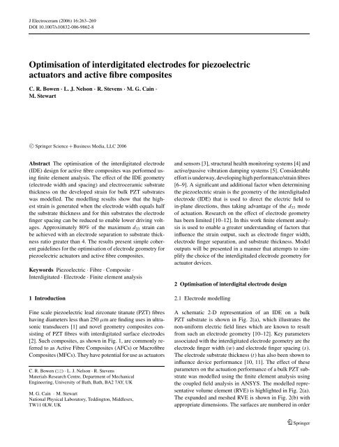
Abstract The optimisation of the interdigitated electrode<br />
(IDE) design for active fibre composites was performed using<br />
finite element analysis. The effect of the IDE geometry<br />
(electrode width and spacing) and electroceramic substrate<br />
thickness on the developed strain for bulk PZT substrates<br />
was modelled. The modelling results show that the highest<br />
strain is generated when the electrode width equals half<br />
the substrate thickness and for thin substrates the electrode<br />
finger spacing can be reduced to enable lower driving voltages.<br />
Approximately 80% of the maximum d 33 strain can<br />
be achieved with an electrode separation to substrate thickness<br />
ratio greater than 4. The results present simple coherent<br />
guidelines for the optimisation of electrode geometry for<br />
piezoelectric actuators and active fibre composites.<br />
Keywords Piezoelectric . Fibre . Composite .<br />
Interdigitated . Electrode . Finite element analysis<br />
1 Introduction<br />
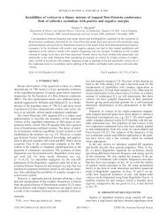
Fine scale piezoelectric lead zirconate titanate (PZT) fibres<br />
having diameters less than 250 μm are finding uses in ultrasonic<br />
transducers [1] and novel geometry composites consisting<br />
of PZT fibres with interdigitated surface electrodes<br />
[2]. Such composites, as shown in Fig. 1, are commonly referred<br />
to as Active Fibre Composites (AFCs) or Macrofibre<br />
Composites (MFCs). They have potential for use as actuators<br />
C. R. Bowen () . L. J. Nelson . R. Stevens<br />
Materials Research Centre, Department of Mechanical<br />
Engineering, University of Bath, Bath, BA2 7AY, UK<br />
M. G. Cain · M. Stewart<br />
National Physical Laboratory, Teddington, Middlesex,<br />
TW11 0LW, UK<br />
and sensors [3], structural health monitoring systems [4] and<br />
active/passive vibration damping systems [5]. Considerable<br />
effort is underway, developing high performance/strain fibres<br />
[6–9]. A significant and additional factor when determining<br />
the piezoelectric strain is the geometry of the interdigitaded<br />
electrode (IDE) that is used to direct the electric field to<br />
in-plane directions, thus taking advantage of the d 33 mode<br />
of actuation. Research on the effect of electrode geometry<br />
has been limited [10–12]. In this work finite element analysis<br />
is used to enable a greater understanding of factors that<br />
influence the strain output, such as electrode finger width,<br />
electrode finger separation, and substrate thickness. Model<br />
outputs will be presented in a manner that attempts to simplify<br />
the choice of the interdigitaded electrode geometry for<br />
actuator devices.<br />
2 Optimisation of interdigital electrode design<br />
2.1 Electrode modelling<br />
A schematic 2-D representation of an IDE on a bulk<br />
PZT substrate is shown in Fig. 2(a), which illustrates the<br />
non-uniform electric field lines which are known to result<br />
from such an electrode geometry [10–12]. Key parameters<br />
associated with the interdigitated electrode geometry are the<br />
electrode finger width (w) and electrode finger spacing (s).<br />
The electrode substrate thickness (t) has also been shown to<br />
influence device performance [10, 11]. The effect of these<br />
parameters on the actuation performance of a bulk PZT substrate<br />
was modelled using the finite element analysis using<br />
the coupled field analysis in ANSYS. The modelled representative<br />
volume element (RVE) is highlighted in Fig. 2(a).<br />
The expanded and meshed RVE is shown in Fig. 2(b) with<br />
appropriate dimensions. The surfaces are numbered in order<br />
Springer
264 J Electroceram (2006) 16:263–269<br />
Table 1 Boundary conditions of displacement (U) electrical potential<br />
(V ) and electrical displacement (D) applied to the RVE<br />
Surface<br />
number Mechanical conditions Electrical conditions<br />
1 Symmetry (U x = 0) D x = 0<br />
2 Symmetry (U y = 0) D y = 0<br />
3 U x coupled V = 0V<br />
4 Free V =+V/2 on electrode,<br />
D y = 0 elsewere<br />
Fig. 1 The construction of the active fibre composite, showing peiezoelectic<br />
ceramic fibres, polymer matrix and interdigitated surface electrodes<br />
to define the appropriate boundary conditions for the model;<br />
these are shown in Table 1.<br />
The model was constructed in the x-y plane for 2-D modelling.<br />
The substrate was defined as a monolithic PZT-5A<br />
material and meshed with 2-D coupled-field elements having<br />
piezoelectric capability. The element was set to plane strain<br />
conditions, implying that the model extends indefinitely in<br />
the z-direction. The element mesh size was set to be fine at<br />
the electrode edge to capture localised effects. The electrode<br />
in Fig. 2(b) was not modelled explicitly, but its presence was<br />
captured by the imposed electrical boundary conditions. Appropriate<br />
mechanical and electrical boundary conditions are<br />
detailed in Table 1.<br />
Previous research [10–12] has shown that the electric field<br />
direction within the substrate is non-uniform and will follow<br />
the field lines depicted in Fig. 2(a). Since the poling<br />
of such IDE devices is performed using the IDEs, the direction<br />
of poling will follow these field lines, and the material<br />
properties will continuously change with respect to<br />
the model axis. In this case, the substrate was considered<br />
to be uniformly poled in the x-direction. This simplification<br />
should prove adequate for large electrode separations<br />
in which the majority of the device response will be attributed<br />
to the region between the electrodes, where the material<br />
is uniformly poled. However, differences between the<br />
modelled and actual response at small electrode separations<br />
could exist as a result of this simplification. Beckert and<br />
Kreher included an inhomogeneous poling state in ANSYS<br />
via a two-step process to examine firstly the electric field<br />
distribution (Step 1) which determined the local poling state<br />
(Step 2) [12].<br />
Model dimensions were varied to investigate the effect<br />
of electrode finger width, electrode finger separation, and<br />
substrate thickness. The figure of merit used to assess the<br />
electrode geometry effects was chosen as the strain (S) developed<br />
in the x-direction per unit applied voltage. Plots of<br />
electric field strength in the x-direction at the substrate centre<br />
axis (y = 0) were also used to gain an insight into the<br />
influence of the IDE geometry.<br />
2.2 Results<br />
2.2.1 Electrode width (w)<br />
Our results, showing the effect of electrode width on the developed<br />
strain, are presented in Fig. 3. Figure 3(a) shows<br />
the strain per unit applied voltage as a function of electrode<br />
width for a range of electrode separations. Firstly, as the electrode<br />
separation is reduced the strain per unit applied voltage<br />
increases. This simply results from a higher electric field<br />
for a given voltage and does not necessarily advocate that<br />
small electrode separations increase performance, as will be<br />
highlighted when the electrode separation (s) results are discussed.<br />
More importantly, this figure shows that there exists<br />
an optimum width of electrode for which the strain per unit<br />
applied voltage is at a maximum, and that this optimum width<br />
is independent of electrode separation and substrate thickness.<br />
The optimum occurs when the electrode width equals<br />
half the substrate thickness (w/t = 0.5). Any deviation from<br />
this value has a greater effect on the strain at small electrode<br />
separations.<br />
To understand the origin of this optimum width it is necessary<br />
to examine how the electric field in the substrate is<br />
Fig. 2 (a) 2-D interdigitated<br />
electrode schematic showing the<br />
electric field lines, geometry<br />
notation, and representative<br />
volume element (RVE). (b) RVE<br />
with numbered boundaries,<br />
appropriate dimensions and an<br />
example of a finite element mesh<br />
Springer
J Electroceram (2006) 16:263–269 265<br />
Fig. 3 Finite element results for electrode width analysis showing (a)<br />
the effect of electrode width on the strain response of an interdigital<br />
electroded PZT substrate (t = 200 μm) for four electrode separations,<br />
and (b) path plots of electric field in x-direction at the substrate centre<br />
axis (y = 0) for three electrode widths (t = 200 μm, s = 1 mm,<br />
V = 0.5 kV)<br />
affected by the electrode width at constant thickness and<br />
separation (t = 200 mm, s = 1 mm). Figure 3(b) demonstrates<br />
the electric field in the poling (x)-direction at the<br />
substrate centre axis (y = 0) for both the optimum w/t ratio,<br />
and for larger and smaller w/t ratios. For wide electrodes<br />
(w = 400 μm, w/t = 2) the electric field strength in the<br />
x-direction between the electrodes is increased, but there also<br />
exists a high proportion of ‘dead area’ under the electrode,<br />
where the field in the x-direction is relatively low. For thin<br />
electrodes (w = 25 μm, w/t = 0.125) the proportion of dead<br />
area is lower, but the electric field in the x-direction is also<br />
low. The w/t ratio that induces optimum strain is a balance<br />
between the proportion of dead area under the electrode and<br />
the strength of electric field in the x-direction between the<br />
electrodes. As already stated, this optimum occurs at a w/t<br />
ratio of 0.5 (w = 100 μm in Fig. 3(b)).<br />
An alternative method of displaying the results of this<br />
analysis is in the form of an electric field vector plot. The<br />
advantage of this representation over the path plot method<br />
is that it allows visualisation of both the magnitude and direction<br />
of the electric field within the entire substrate. This<br />
reveals important information not available from the path<br />
plot method presented previously. Figure 4 shows vector<br />
plots of the electric field within the modelled RVE for the<br />
three electrode widths presented in Fig. 3(b). The direction<br />
of the electric field is denoted by the arrow direction, while<br />
the greyscale of the arrow indicates the field strength. The<br />
electrode location is indicated by the grey region, on the top<br />
surface of each of the substrates.<br />
At large electrode widths, there is a significant dead zone<br />
below the electrodes, where the field is perpendicular to the<br />
actuation direction (x). For thin electrodes, a relatively weak<br />
field is observed between the electrode fingers. In addition to<br />
confirming the results of the path plot analysis (Fig. 3(b)), the<br />
vector plots presented in Fig. 4 show that a field concentration<br />
exists at the electrode edge. The magnitude of the field<br />
strength in this location increases as the w/t ratio is reduced,<br />
whilst the direction remains largely unaffected. Modelling<br />
and actual device studies [10, 13], show that the non-uniform<br />
fields present at electrode edges can cause cracking of the<br />
piezoelectric substrate resulting in device deterioration. This<br />
is a consequence of the large and non-uniform mechanical<br />
stresses induced via the piezoelectric effect. Although induced<br />
stresses are not quantified in this study, they are an<br />
important effect that could lead to device failure. These effects<br />
need to be considered in future modelling, which could<br />
also investigate the effect of functionally graded fibres, and<br />
the influence of polymer layers inserted between the electrode<br />
and the piezoelectric fibre. These polymer layers could<br />
act as a buffer zone for the field and stress concentration<br />
effects, although this would be at the expense of a reduced<br />
strain [10, 12].<br />
2.2.2 Substrate thickness (t)<br />
With the optimum electrode width determined, and the underlying<br />
reasons understood, it is possible to investigate the<br />
effect of substrate thickness on the strain output of the device.<br />
Results summarising the effect of substrate thickness<br />
are presented in Fig. 5. In this analysis, the substrate thickness<br />
was varied while the electrode separation and w/t ratio<br />
remained constant (s = 1 mm, w/t = 0.5). Figure 5(a), which<br />
plots strain per unit applied voltage versus substrate thickness,<br />
highlights that a reduction in the substrate thickness<br />
Springer
266 J Electroceram (2006) 16:263–269<br />
Fig. 4 Vector plots of electric<br />
field distribution within the<br />
modelled RVE of an IDE<br />
structure with varying electrode<br />
widths. Voltage = 0.5 kV, PZT<br />
thickness = 200 μm, electrode<br />
separation = 1.0 mm. The<br />
electrode locations are indicated<br />
by the light grey region, on the<br />
surface of each substrate<br />
Fig. 5 Finite element results for substrate thickness analysis showing<br />
(a) the effect of substrate thickness (for w/t = 0.5 and s = 1 mm) on<br />
the strain response of an interdigital electroded substrate, and (b) Path<br />
plots of electric field in x-direction at the substrate centre axis (y = 0)<br />
for three substrate thicknesses (w/t = 0.5, s = 1 mm, V = 0.5 kV)<br />
increases the strain developed. The reason behind the increased<br />
strain is twofold, and can be seen by examination of<br />
Fig. 5(b), which shows electric field in the x-direction at the<br />
substrate centre axis for three values of substrate thickness.<br />
Firstly, as the substrate thickness is reduced the electric field<br />
becomes directed into the in-plane direction over a shorter<br />
distance, reducing the proportion of ‘dead area’. Secondly, as<br />
the substrate thickness is reduced, the electric field between<br />
the electrodes becomes larger. Both these effects result from<br />
the opposing electrodes becoming closer as the substrate<br />
thickness is reduced, when they exert a stronger influence<br />
on one another. To quantify this effect, a 17% increase in the<br />
strain per unit voltage can be expected when the substrate<br />
is reduced from a 200 to 25 μm. The results obtained have<br />
Springer
J Electroceram (2006) 16:263–269 267<br />
shown that thin substrates, and electrodes widths conforming<br />
to the optimum w/t ratio of 0.5, provide increased actuation<br />
performance.<br />
2.2.3 Electrode separation (s)<br />
The final parameter to be examined for optimisation is the<br />
electrode finger spacing. It has already been shown that ‘dead<br />
zones’ exist below the electrode fingers, with the field magnitude<br />
being low, and out of plane. With large electrode separations<br />
the proportion of dead zones is low, but the voltage<br />
required to operate the device is high. In contrast, small electrode<br />
separations reduce the operational voltage, but increase<br />
the proportion of ‘dead zone’. There exists a compromise<br />
between the achievable actuation strain and operational voltage.<br />
Simply plotting the results of actuation strain per unit<br />
applied voltage as a function of electrode separation gives<br />
little insight into the effects of electrode separation. To gain<br />
more from the results it is desirable to quantify how much<br />
strain degradation arises from the dead zones. This can be<br />
achieved by comparing the FE results to an ‘ideal actuator’<br />
in which there are no dead zones (all electric field vectors<br />
aligned in the in-plane direction). A schematic of the electric<br />
field distribution in a true ‘IDE actuator’, and the desired<br />
‘ideal actuator’ is presented in Fig. 6<br />
To quantify the degradation in actuation performance, the<br />
IDE strain response is compared to an idealised situation<br />
in which the field is uniform and aligned in the actuation<br />
direction. For a monolithic piezoelectric material electroded<br />
on opposite faces separated by a distance s, the strain per<br />
unit voltage as a function of electrode separation will obey<br />
the relationship in Eq. (1).<br />
S<br />
V = d 33<br />
s<br />
To investigate the effect of electrode separation, a model with<br />
afixedw/t ratio, 0.5, was constructed, and the electrode separation<br />
was varied from 0.01 to 100 mm. Figure 7 summarises<br />
the results obtained. Figure 7(a) shows the strain response as<br />
a function of electrode separation for a substrate thickness of<br />
25 μm and contains two data sets, the first is from the finite<br />
element analysis and is labelled ‘IDE response.’ This data<br />
shows that decreasing the electrode separation increases the<br />
strain per unit voltage; this suggests a small electrode separation<br />
is desirable for increased actuation.<br />
(1)<br />
Fig. 6 Schematic<br />
representations of the electric<br />
field vector for the interdigitaded<br />
geometry electrode, and an ideal<br />
case with no dead zones<br />
-V<br />
+V<br />
s<br />
-V<br />
IDE Actuator<br />
Strain per unit applied voltage<br />
determined from finite element<br />
modelling.<br />
-V<br />
+V<br />
s*<br />
-V<br />
Ideal Actuator<br />
Strain per unit applied voltage<br />
determined from electromechanical<br />
relationships.<br />
-V +V -V<br />
Fig. 7 Results of the electrode separation analysis showing (a) the IDE and idealised strain response as a function of electrode separation, and (b)<br />
the strain response of an IDE substrate compared to that of the idealised strain response for three substrate thicknesses<br />
Springer
268 J Electroceram (2006) 16:263–269<br />
The deviation of the IDE strain S IDE , from ideal response<br />
S ideal , can be used to quantify the degradation in actuation<br />
resulting from the dead zones directly below the electrode<br />
area. This degradation is shown in Fig. 7(b), which plots<br />
S IDE /S ideal as a function of electrode separation for three<br />
PZT thicknesses. In all cases the electrode width was set<br />
so that w/t = 0.5. At large electrode separations (>10 mm)<br />
the response is close to that of the ideal case. As the electrode<br />
separation is reduced the dead zones begin to dominate<br />
the response, and the IDE strain starts to diminish compared<br />
to the idealised response. Since a primary reason for<br />
using an IDE is to take advantage of the d 33 response, which<br />
is approximately twice as large as the d 31 response, once<br />
the reduction in actuation is greater than 50%, this benefit<br />
is lost. From Fig. 7(b) it is apparent that for thinner substrates<br />
the electrode separation can be reduced significantly<br />
while still maintaining a high proportion of the optimum d 33<br />
response.<br />
The extension of this work to fibre-matrix substrates used<br />
for active fibre composites (Fig. 1) implies small diameter<br />
fibres are required to enable production of thin substrates.<br />
Thus manufacturing techniques have not only to be capable<br />
of producing high quality fibres, but also small diameters fibres.<br />
The graph presented in Fig. 7(b) can be used as a design<br />
guide for IDEs. For example, to obtain at least 80% of the d 33<br />
response, electrode separations must satisfy s/t > 4. Using<br />
this guideline, substrates with a thickness of 200 μm require<br />
electrode separations greater than 0.8 mm. This separation<br />
reduces to 0.1 mm for a substrate thickness of 25 μm. This<br />
is significant result since a reduced electrode separation enables<br />
lower driving voltages to be used, which at present are<br />
typically very high. A clear benefit from using thin substrates<br />
(small diameter fibres in AFCs) now becomes apparent. Thus<br />
manufacturing techniques for fibres must be capable of producing<br />
high quality smaller diameter fibres, along with close<br />
control over IDE geometry.<br />
3 Conclusions<br />
Modelling of the interdidgitated electrode structure on a PZT<br />
substrate has given an insight into how the strain response is<br />
affected by electrode width, substrate thickness and electrode<br />
finger separation. The optimum strain was found to occur at<br />
an electrode width to substrate thickness (w/t) ratio of 0.5.<br />
A reduction in the substrate thickness has been shown to increase<br />
the strain output of the device by reducing ‘dead areas’<br />
and increasing the field level between the electrode fingers.<br />
Finally, it was shown that 80% of the maximum d 33 strain<br />
can be achieved with an electrode separation to substrate<br />
thickness (s/t) ratio greater than 4. This has important implications<br />
since thin substrates allow smaller electrode separations,<br />
allowing large reductions in the operational voltage.<br />
As a result of these findings it becomes clear that fibre<br />
manufacturing techniques have not only to be capable of<br />
producing high quality fibres, but also fibres with small diameters.<br />
The data presented provides simple design guidelines<br />
for IDE patterns on piezoelectric actuators and active fibre<br />
composites.<br />
Material property data<br />
Table 2 Material property data for PZT-5A<br />
[14] used for the finite element analysis<br />
Material property<br />
e 33<br />
e 31<br />
e 15<br />
Value<br />
ε T/ε0<br />
33<br />
1700<br />
ε T/ε0<br />
11<br />
1730<br />
c11<br />
E<br />
c12<br />
E<br />
c13<br />
E<br />
c33<br />
E<br />
c44<br />
E<br />
15.8 Cm −1<br />
−5.2 Cm −1<br />
12.3 Cm −1<br />
12.0 × 10 10 Pa<br />
7.52 × 10 10 Pa<br />
7.51 × 10 10 Pa<br />
11.1 × 10 10 Pa<br />
2.1 × 10 10 Pa<br />
Acknowledgment The authors would like to acknowledge NPL and<br />
the University of Bath for funding this research.<br />
References<br />
1. R.J. Meyer, T. R. Shrout, and S. Yoshikawa, “Development of ultrafine<br />
scale piezoelectric fibers for the use in high frequency 1-3<br />
transducers,” in Proc. 10th IEEE Int. Symp. On Applications of<br />
Ferroelectrics, edited by B.M. Kulwicki et al. (IEEE, New York,<br />
1996), p. 547.<br />
2. L.J. Nelson, “Smart piezoelectric fibre composites,” Materials Science<br />
and Technology, 18, 1245 (2002).<br />
3. A. Schonecker, U. Keitel, W. Kreher, D. Sporn, W. Watazka, and<br />
K. Pannkoke, Ferroelectrics, 224, 435 (1999).<br />
4. M.J. Schulz, M.J. Sundaresan, A. Ghoshal, and P.F. Pai, “Active<br />
fiber composites for structural health monitoring,” in Proc. of SPIE,<br />
edited by C.S. Lynch (SPIE, Bellingham USA, 2000), vol. 3992,<br />
pp. 13–24.<br />
5. S. Yoshikawa, U. Selvaraj, K.G. Brooks, and S.K. Kurtz, “Piezoelectric<br />
PZT tubes and fibres for passive vibration damping,” in<br />
Proc. 8th IEEE Int. Symp. on Applications of Ferroelectrics, edited<br />
by M. Liu et al. (IEEE, New York, 1992), pp. 269–272.<br />
6. H.B. Strock, M.R. Pascucci, M.V. Parish, A.A. Bent, and T.R.<br />
Shrout, “Active PZT fibers, a commercial production process,” in<br />
Proc. of SPIE, edited by W. Wuttig (SPIE, Wellingham USA, 1999),<br />
vol. 3675, pp. 22–31.<br />
7. R. Meyer, T. Shrout, and S. Yoshikawa, J. Am. Ceram. Soc., 81, 861<br />
(1998).<br />
8. J.D. French and R.B. Cass, Am. Ceram. Soc. Bull., 77, 61 (1998).<br />
9. F. Meister, D. Vorbach, F.Niemz, T. Schulze, and E. Taeger, Materialwiss.<br />
Werkst., 34, 262 (2003).<br />
Springer
J Electroceram (2006) 16:263–269 269<br />
10. D.J. Warkentin, “Modeling and electrode optimisation for torsional<br />
IDE piezoceramics,” in ‘Smart Structures and Materials 2000:<br />
Smart Structures and Intergrated Systems,’ in Proc. of SPIE,<br />
edited by N.M. Werely (SPIE, Belingham USA, 2000), vol. 3985,<br />
pp. 840–854.<br />
11. N. Hagood, R. Kindel, K. Ghandi, and P. Gaudenzi, “Improving<br />
transverse actuation of piezoceramics using interdigitated<br />
surface electrodes,” in Proc. of SPIE, edited by N.W.<br />
Hagood (SPIE Bellingham USA, 1993), vol. 1917, pp. 341–<br />
352.<br />
12. W. Beckert and W.S. Kreher, Comp. Mat. Sci., 26, 36 (2003).<br />
13. C.R. Bowen, A. Bowles, S. Drake, N. Johnson, and S. Mahon,<br />
Ferroelectrics, 228, 257 (1999).<br />
14. D. Berlincourt, H.H.A. Krueger, and C. Near, “Properties of<br />
piezoelectric ceramics,” Technical Publication TP = 226, Morgan<br />
Electroceramics (Jan. 2002).<br />
Springer


![[Luyben] Process Mod.. - Student subdomain for University of Bath](https://img.yumpu.com/26471077/1/171x260/luyben-process-mod-student-subdomain-for-university-of-bath.jpg?quality=85)