click here to download User's Manual. - Spc960.com
click here to download User's Manual. - Spc960.com
click here to download User's Manual. - Spc960.com

Create successful ePaper yourself
Turn your PDF publications into a flip-book with our unique Google optimized e-Paper software.
USER’S MANUAL<br />
Au<strong>to</strong>motive Diagnostic Scanner<br />
ATTENTION: VERY IMPORTANT<br />
In this manual you will find the answers <strong>to</strong> all your questions. Read it carefully<br />
Language: English<br />
Version software: V2007-1<br />
<strong>Manual</strong> Version: 2-Feb-07<br />
1 of 34
INDEX<br />
Recommendations-Warnings 4<br />
Introduction 5<br />
* Main Functions 5<br />
General Features 5<br />
* Use of SPCMAX 5<br />
* Computer minimum requirements 5<br />
* SPCMAX vehicle connection 6-7<br />
SPCMAX Presentation 7<br />
* Component list 7-8<br />
Installation 8<br />
* Connection diagram 8-9<br />
* Leds Code 9<br />
* Software installation 9-10<br />
How <strong>to</strong> use 10<br />
* First Screen 10<br />
* Configure 11<br />
* Tester 11<br />
* Introduction <strong>to</strong> Cus<strong>to</strong>mer Database 12<br />
* Language seleccion 12<br />
* Upgrade (Via Internet) 12<br />
* Uninstall 13<br />
* Date and Time 13<br />
Model and System Selection (Second Screen) 14<br />
* Make code and systems available 14<br />
* Selection by system 14<br />
* Selection by model 14<br />
* Back 15<br />
Connection <strong>to</strong> the vehicle (Third Screen) 15<br />
* Diagnostic connec<strong>to</strong>r location 15<br />
* Connection <strong>to</strong> diagnostic connec<strong>to</strong>r - Doubts and risks 15<br />
* Pin-Out (Connections) 16<br />
* Measurements (Live Data) 16<br />
* Special mode: VW Live data 17<br />
Fault Reading (Forth Screen) 18<br />
* General aspects 18<br />
* Basic adjustment or Au<strong>to</strong>adaptation 18<br />
* Actua<strong>to</strong>rs test 18<br />
* Dynamic test 18<br />
* Faults memory erasure 19<br />
Data base 19<br />
* Access <strong>to</strong> database 19<br />
* How <strong>to</strong> use the database 20-25<br />
2 of 34
Data Printing 25<br />
* Incompatible printers 25<br />
Trouble code reading through OBDII screen 26<br />
Reset service screen 26<br />
Voltmeter 27<br />
* Description 27<br />
* Warnings 28<br />
Oscilloscope 28<br />
* Description 28<br />
* Warnings 29<br />
Special functions 30<br />
* <strong>Manual</strong> adjustment Marelli 1AVB/1AVS/1AVP (VW) 30<br />
Blue<strong>to</strong>oth 30<br />
* Problems with interferences 30<br />
* Special warning 30<br />
Specifications 31<br />
* General SPCMAX specifications 31<br />
* 2 Channel Digital oscilloscope 31<br />
* Voltmeter 32<br />
Regula<strong>to</strong>ry Information – Declaration of Conformity 33<br />
3 of 34
Recommendations - Warnings<br />
1. Verify that your workshop electrical system has cable <strong>to</strong> ground. (Mass)<br />
2. DO NOT connect or disconnect USB port with PC on.<br />
3. Turn off the screensaver and the antivirus. These features may cause communication errors or Windows errors.<br />
4. DO NOT run any program while using the SPCMAX.<br />
5. Keys and menues with letters colored in LIGHT GREY ARE NOT available, while the ones colored DARK GREY<br />
are available.<br />
6. WARNING / CAUTION: Seat-belt pretensioners annulment<br />
If you annul one or more seat-belt pretensioners we recommend taking in<strong>to</strong> account the following items:<br />
a) The annulment of one or more seat-belt pretensioners implies that they will not work in case of accident<br />
(connected or not). The fault light will remain off, SHOWING THAT ALL THE SYSTEM IS WORKING PROPERLY.<br />
b) Warn and explain <strong>to</strong> the vehicle owner the effects of the system reconfiguration he is requiring.<br />
c) DEMAND AND FILE AN ORDER SIGNED BY THE VEHICLE OWNER, giving you the order and authority <strong>to</strong><br />
change airbag’s original configuration.<br />
d) Once the system has been reconfigured, make a fault reading confirming that the new configuration is the one<br />
ordered and authorized by the vehicle owner. This is displayed on the <strong>to</strong>p right side of the fault screen.<br />
(Superimposed on the red panel)<br />
e) If you want, you can print a form with the order and authorization <strong>to</strong> be filled and signed by the vehicle owner.<br />
EXPLAIN TO THE VEHICLE OWNER THE RISKS OF FOLLOWING THIS PROCEDURE.<br />
"HAVING NO CONTROL OVER THE OPERATOR PERFORMING THE RECONFIGURATION, THE SCANNER<br />
MANUFACTURING COMPANY, ITS REPRESENTATIVES AND DISTRIBUTORS, DO NOT TAKE ANY<br />
RESPONSIBILITY FOR THE CONSEQUENCES THAT MAY RESULT FROM THE IMPROPER USE OF THIS<br />
PROCESS."<br />
IMPORTANT: When feeding scanner always connect negative (black banana) first. If you<br />
disconnect scanner leave the negative for the end.<br />
If you remove negative first, mass could be done through other cables. (Green or yellow). This<br />
will cause the scanner <strong>to</strong> burn and will have <strong>to</strong> replace internal plates.<br />
If the computer has losses of energy or you feed scanner with a battery charger which has a<br />
cable in common with a 220V feeding remember <strong>to</strong> follow these instructions, if not t<strong>here</strong> is a<br />
serious risk <strong>to</strong> burn the interphase.<br />
4 of 34
INTRODUCTION<br />
SPCMAX princippal functions<br />
1. Location and actual diagram of the Diagnosis Input Socket (connec<strong>to</strong>r) for loaded systems.<br />
2. Fault reading: By Data flow.<br />
3. N/A<br />
4. Fault memory erasure.<br />
5. By Data Flow, shows in reaal time the sensor values being processed by the different ECU (Electronic Control<br />
Unit).<br />
6. Allows <strong>to</strong> correct the Ignition Advance, RPM or richness (when the ECU allows it).<br />
7. Allows <strong>to</strong> perform the Au<strong>to</strong>adaptation (when the ECU allows it)<br />
8. Ford EEC IV: make the KOEO and KOER tests.<br />
9. Actua<strong>to</strong>rs Test and/or Basic Adjustment (when the ECU allows it).<br />
10. Reading in: ABS - Airbag - Climatization - Au<strong>to</strong>matic Gear - Body - 4WD - CAN (see makes enabled).<br />
11. Instrument Panel: Reset Service, diagnosis, actua<strong>to</strong>rs. (see makes enabled).<br />
12. Inmovilizer: Faults, recoding and keys synchronization (see makes enabled).<br />
13. CARB OBD II: fault reading in OBD. Generic. Different systems: Injection, ABS, etc.<br />
14. OBD II: per Make pro<strong>to</strong>col, Sensors - Frozen and Lambda value reading - Memory erasure.<br />
15. Pin-Out: shows the connection of each pin of selected ECU.<br />
16. Help: offers generic information about the different injection systems.<br />
17. Data base: Incorporate cus<strong>to</strong>mers and vehicle data, including fault reading and live data.<br />
18. Measurements graph: Allows <strong>to</strong> perform the road test, showing the evolution of the values measured by sensors.<br />
(Up <strong>to</strong> 4 grpahics at the same time)<br />
19. Reference range: indicates the range in which the values should be found under normal conditions.<br />
GENERAL FEATURES<br />
The SPCMAX is a scanner specially designed <strong>to</strong> read the fault memory of different vehicles Electronic Control Unit (ECU).<br />
Detection of these faults depends on the vehicle and the system it has on SPCMAX. SPCMAX only performs the reading<br />
and interpretation of the data.<br />
Equipment includes: PROGRAM, INTERFACE, CONNECTION CABLES and BAG.<br />
Computer minimum requirements<br />
Pentium IV 1.4 Ghz with:<br />
• 256 MB RAM<br />
• 2 Gb Hard disk<br />
• CD-ROM<br />
• Windows XP<br />
• 1 USB 2.0 port.<br />
Connections<br />
The SPCMAX is connected <strong>to</strong> all vehicles through 1, 2 or 3 terminals (yellow, green and and/or blue) <strong>to</strong> DLC (Data Link<br />
connec<strong>to</strong>r) The red and black terminals are connected <strong>to</strong> the positive (+) and negative (-) of the vehicle <strong>to</strong> be tested.<br />
5 of 34
Next you will find the different ways <strong>to</strong> connect SPCMAX <strong>to</strong> vehicle:<br />
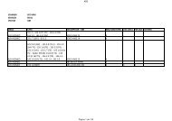
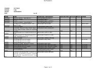
Pins for diagnostic connec<strong>to</strong>rs:<br />
For those vehicles without OBDII connec<strong>to</strong>r, SPCMAX includes connection pins. Next you will find a make reference <strong>to</strong><br />
know which pin <strong>to</strong> use for which make.<br />
NOTE: These are referencial indications. Pins may be used for more makes than indicated. The vehicle connec<strong>to</strong>rs may<br />
present changes not known by Condistelec.<br />
1. Old Ford / Old VW / Chrysler 6 Pin<br />
2. Alfa Romeo / Fiat 3 Pin / Nissan / OBDII<br />
3. BMW<br />
4. Daihatsu / Mitsubishi / Peugeot 30 pin<br />
5. Peugeot 2 pin / GM 12 pin / GM 10 pin<br />
6. Rover 3 pin<br />
7. MB 14 pin<br />
8. MB 38 pin<br />
9. Renault<br />
6 of 34
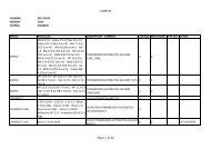
Component List<br />
SPCMAX PRESENTATION<br />
Item # Qty Code Description<br />
1 1 SMAX SPC MAX Interfase<br />
2 1 SOFTCD CD Software<br />
3 1 MALE Bag<br />
4 1 CLAR Long cable (5mts)<br />
5 1 CRCA RCA M-M cable<br />
6 1 CENC Cigarlighter cable<br />
7 1 CCOC Crocodille cable<br />
8 1 C5PU 5 end cable<br />
9 1 CUSB USB 2.0 cable<br />
10 1 CRCAWH RCA Cable white for oscilloscope<br />
11 1 CRCABL RCA Cable blue for oscilloscope<br />
12 1 CMAOSC Mass Cable for oscilloscope<br />
13 1 FOBD OBDII connec<strong>to</strong>r<br />
14 1 PVA 19 pins Green/Yellow<br />
15 1 CBAL Power supply cable<br />
16 KBLU Blue<strong>to</strong>oth dongle (OPTIONAL)<br />
7 of 34
List subject <strong>to</strong> change according <strong>to</strong> version our country. Subject <strong>to</strong> changes without notice.<br />
INSTALLATION<br />
SPCMAX CONNECTION DIAGRAM<br />
PC connection side<br />
1. ECU Connection Led<br />
2. PC Connection Led<br />
3. RS232 (PC Connection)<br />
4. USB (PC Connection)<br />
5. Blue<strong>to</strong>oth (wireless connection <strong>to</strong> PC)(Optional)<br />
8 of 34
Vehicle connection and power supply side<br />
1. Au<strong>to</strong>matic pin selection Led<br />
2. Power supply Led<br />
3. Oscilloscope Channel 1<br />
4. Oscilloscope Channel 2<br />
5. Connection <strong>to</strong> vehicle<br />
6. Power supply Jack - 9 <strong>to</strong> 50 V/DC<br />
ATTENTION: in order <strong>to</strong> iniciate software, SPCMAX has <strong>to</strong> be connected <strong>to</strong> PC. T<strong>here</strong> are 3 possible ways: RS232<br />
(Serial), USB or Blue<strong>to</strong>oth (optional). Keep in mind it only connects through one of them at a time.<br />
Leds code:<br />
Code Description Led operation<br />
Power Power supply On: interface power on<br />
(Red)<br />
Off: interface power off<br />
Pin search Au<strong>to</strong>matic pin selection<br />
(Blue)<br />
Slow flashing: Stand by<br />
Fast flashing: pin selection<br />
ECU ECU Connection Slow flashing: Stand by<br />
(Yellow)<br />
On: dialog between MAX and ECU<br />
PC PC Connection Slow flashing: no connection <strong>to</strong> PC<br />
(Green)<br />
On or Off: Stand by<br />
Fast flashing: dialog with PC<br />
ATTENTION: When connecting USB, the red led will be slightly on.<br />
However, it does not mean the power is on. It means interface is connected <strong>to</strong> USB<br />
Bip:<br />
Interfase bips when software dialogs with it.<br />
SPCMAX SOFTWARE INSTALLATION<br />
Turn on the PC (computer).<br />
1. Insert the CD.<br />
9 of 34
2. A screen will au<strong>to</strong>matically open, double <strong>click</strong> on “INSTALL”.<br />
3. If the screen does not open, go <strong>to</strong> Start, Execute and write "X:\INSTALL", w<strong>here</strong> "X" is the letter belonging <strong>to</strong> the CDrom<br />
Drive (usually "D").<br />
4. If a message reads: "An access violation has occurred when copying the file", <strong>click</strong> on "Omit" and the installation will<br />
go on (it happens when t<strong>here</strong> are different versions of some windows libraries).<br />
5. To operate the SPCMAX program in Windows, <strong>click</strong> on the SPCMAX icon in your desk<strong>to</strong>p.<br />
INCOMPATIBILITIES<br />
• T<strong>here</strong> can not be ANY OTHER PROGRAM IN MEMORY OR IN EXECUTION in the P.C.(computer) (for example Office,<br />
etc.)<br />
• If t<strong>here</strong> are any programs loaded when Windows starts, they must be CLOSED BEFORE STARTING SPCMAX<br />
software.<br />
• In Notebooks battery charge control program MUST NOT be working.<br />
TO PREVENT DIFFICULTIES, FOLLOW THE MENTIONED RECOMMENDATIONS<br />
PROBLEMS DURING THE INSTALLATION.<br />
If for any reason an incovenience occurs during installation: Reset computer and start again. If it happens again, note down<br />
the problem, go <strong>to</strong> www.SPCMAX.com and fill "Technical Support" form.<br />
Remember: SPCMAX interface must be connected <strong>to</strong> PC and power on (from 9 <strong>to</strong> 50V) for the program <strong>to</strong> run.<br />
If the interfase is not connect <strong>to</strong> power supply, software WILL NOT RUN.<br />
HOW TO USE<br />
SPCMAX – FIRST SCREEN<br />
Figure 2 - First Screen "SPCMAX"<br />
In this screen you will find: "Name", "Garage data" (name-address-phone) and "Date and time", which are directly read<br />
from the PC (computer).<br />
Serial number of the scanner, is showed in the middle right of the screen in yellow.<br />
In this example, the number is: MEC0001AR<br />
10 of 34
Is very important <strong>to</strong> know your scanner number because it will be required <strong>to</strong> give you technical support.<br />
"SCANNER”: To start using SPCMAX, <strong>click</strong> on “SCANNER”<br />
“OSCILLOSCOPE”: but<strong>to</strong>n <strong>to</strong> access Oscilloscope function. (For more information, go <strong>to</strong> page 28)<br />
“VOLTMETER”: but<strong>to</strong>n <strong>to</strong> access Voltmeter function. (For more information, go <strong>to</strong> page 27)<br />
» CONFIGURE<br />
OPTIONS AVAILABLE ON THIS SCREEN:<br />
SPCMAX software configures au<strong>to</strong>matically. Au<strong>to</strong>matic configuration will work in most PCs. If not, port number can be<br />
changed using the Configure menu. Once configured, the options are saved.<br />
AUTOCONFIGURATION<br />
In "Configure" menu you can perfom "AUTOCONFIGURATION", which normally performs the correct configuration. If<br />
necessary, you may do a manual configuration.<br />
MANUAL CONFIGURATION<br />
Go <strong>to</strong> "CONFIGURE" and then the option "CONFIGURE" at the end of the list. A screen will open asking you <strong>to</strong> enter the<br />
password; which is: "SPCMAX". After that you will be able <strong>to</strong> choose the <strong>Manual</strong> or Au<strong>to</strong>matic configuration.<br />
You must <strong>click</strong> the required option in the "CONFIGURE" menu list and will be au<strong>to</strong>matically saved. If any other change is<br />
required you must repeat all the operation."<br />
HEARING SOUNDS: this function is enabled by default. This function allows the scanner <strong>to</strong> talk.<br />
To disable this function: go <strong>to</strong> "CONFIGURE" and then the option "SOUNDS????" at the end of the list. A screen will open<br />
asking you <strong>to</strong> enter the password: "SPCMAX".<br />
Click on “HEARING SOUNDS”: The check will desapear, showing the scanner has this function disabled.<br />
Remember: for the scanner <strong>to</strong> talk, your PC has <strong>to</strong> have soundcard and speakers (The speakers have <strong>to</strong> be connected <strong>to</strong><br />
power supply)<br />
ATTENTION: WE RECOMMEND AUTOCONFIGURATION.<br />
» TESTER<br />
Figure 3 - Tester<br />
The correct running of the TEST ensures that the system composed by: PC (computer), its configuration, interface and all<br />
connections work properly.<br />
On the First Screen ("SPCMAX"), between the "Configure" and "Database" options, the "TESTER" option allows you <strong>to</strong><br />
perform the SPCMAX working test. This test is explained in the program. (Read carefully the messages on screen). NO car<br />
is needed <strong>to</strong> perform the test, only make the connections shown on screen and then start.<br />
11 of 34
TROUBLE SHOOTING<br />
• IF THE SELF-TEST IS OK BUT DOES NOT ALLOW TO ESTABLISH COMMUNICATIONS: verify mass and car<br />
connections. If connected through the cigarlighter, check that carlighter is in optimal operating conditions.<br />
• Any incorrect option avoid the correct functioning of SPCMAX<br />
WARNING: SELF-TEST is au<strong>to</strong>matically performed each time SPCMAX software starts. Only if the au<strong>to</strong>test did not end<br />
properly the last time will be executed again.<br />
» CUSTOMER DATABASE<br />
Click on the DATABASE menu, choose VEHICLE FILE. Once you <strong>click</strong> on this option will show the VEHICLE FILE screen.<br />
It will show: Workshop Data, Cus<strong>to</strong>mer Data and Car Data.<br />
To find a more detailed explanation, go <strong>to</strong> Data Base.<br />
» LANGUAGE<br />
Allows you <strong>to</strong> choose language from a list.<br />
» UPGRADE<br />
When entering this menu, the SPCMAX software will close au<strong>to</strong>matically and open a new window.<br />
When activating this function through the “Start Download” but<strong>to</strong>n, the program will connect <strong>to</strong> Internet (you may use a<br />
wideband or a modem connection) and will try <strong>to</strong> <strong>download</strong> the last software version. If it is available, it will be <strong>download</strong>ed<br />
in<strong>to</strong> the hard disk. Once the process ends, installation program will start au<strong>to</strong>matically.<br />
The installation is au<strong>to</strong>matic, without user intervention. It s<strong>to</strong>res the upgrade in the UPDATE folder, inside the folder w<strong>here</strong><br />
the SPCMAX program is installed, allowing <strong>to</strong> repeat upgrade if necessary.<br />
12 of 34
» DATE AND TIME<br />
To change date or time in Windows, go <strong>to</strong>: My PC, Control Panel, <strong>click</strong> on Date and Time and Clock/Calendar will appear.<br />
To change date and time format, go <strong>to</strong>: My PC, then <strong>to</strong> Control Panel, then <strong>to</strong> Regional Configuration.<br />
If time of your PC (computer) delays or forwards, repair it <strong>to</strong> work properly. SPCMAX software uses these times <strong>to</strong><br />
operate.<br />
13 of 34
Model and System Selection – SECOND SCREEN<br />
Figure 7 - System Selection<br />
Figure 8 - Model Selection<br />
On this screen you choose the vehicle according <strong>to</strong> Type of system or Year, Model and Engine.<br />
Top right you will find the SYSTEMS and MODELS options. Click on the desired option.<br />
• SYSTEMS: allows <strong>to</strong> select manually vehicle make and type of system (Injection-ABS-Airbag, etc) available.<br />
• MODELS: allows <strong>to</strong> enter <strong>to</strong> Injection, Diesel, ABS or Airbag choosing: Make - Manufacturing year - Model - Engine<br />
Code and KW.<br />
» MAKES CODE AND SYSTEMS AVAILABLE (-) (+) (X) (*)<br />
Systems available have the following signs on the right which indicates the available functions.<br />
(-) Faults.<br />
(I) Pin out<br />
(+) Faults and Pin out.<br />
( X ) Faults and Measurements. (Live data)<br />
( * ) Faults, Pin out and Measurements. (Live data)<br />
» SELECTION BY SYSTEM<br />
On the <strong>to</strong>p of the screen you will find different but<strong>to</strong>ns with the types of systems available, <strong>click</strong> on them different systems.<br />
(Injection, Diesel Abs, Airbarg, etc) Select a make from the VEHICLE BRAND list located on the left of the screen. It will<br />
display systems for that vehicle brand and type of system in the list located on the right.<br />
With some vehicle brands some but<strong>to</strong>ns may appear below the systems list. These but<strong>to</strong>ns allow au<strong>to</strong>detection of systems<br />
according <strong>to</strong> make or type, depending on the case. This way the correct system will be au<strong>to</strong>matically selected. Click on<br />
these but<strong>to</strong>ns <strong>to</strong> access au<strong>to</strong>detection mode. Third Screen will au<strong>to</strong>matically be reached after performing au<strong>to</strong>detection.<br />
ATTENTION: About Au<strong>to</strong>detection of systems marked with # : systems NOT marked with # cannot be detected, but<br />
communication can be erroneously established due <strong>to</strong> its similitude with other systems. Verify the faults returned by the<br />
system (on the Trouble Code Reading screen) are possible, if not, you must select another system without using<br />
au<strong>to</strong>detection.<br />
After selecting system, <strong>click</strong> on SCANNER <strong>to</strong> read the faults, measurements and make connection with ECU.<br />
» SELECTION BY MODEL<br />
Select manufacture year of the vehicle, model and finally engine.<br />
After selecting this, <strong>click</strong> on SCANNER <strong>to</strong> go <strong>to</strong> connection screen.<br />
14 of 34
» BACK<br />
Click on BACK but<strong>to</strong>n <strong>to</strong> return <strong>to</strong> previous screen.<br />
Connection <strong>to</strong> the Vehicle – THIRD SCREEN<br />
Figure 10 - Connection in the Vehicle.<br />
»DIAGNOSTIC CONNECTOR LOCATION<br />
On the left side of the screen you may find: A car drawing and several car pho<strong>to</strong>s (depending on the make and model<br />
selected), w<strong>here</strong> the possible locations of the Diagnosis Connec<strong>to</strong>r are shown. The location depends on each particular<br />
vehicle and may not apply <strong>to</strong> other models.<br />
Click on any image <strong>to</strong> enlarge it. To return <strong>to</strong> the small image, <strong>click</strong> on it again.<br />
The car image with two views specifies all possible locations of the diagnosis input switch connec<strong>to</strong>r. Image used is only an<br />
example and applies <strong>to</strong> all the vehicles in the selected system.<br />
Pho<strong>to</strong>s were taken from the vehicles specified below the image. They may or not apply <strong>to</strong> other models.<br />
All the images and pho<strong>to</strong>s are property of SPC Group ® All rights reserved<br />
»CONNECTION TO DIAGNOSTIC CONNECTOR - DOUBTS AND RISKS<br />
On the right side of the third screen are shown skematic drawings of the diagnosis input switch connec<strong>to</strong>r. All possibilities<br />
according make and selected systems are shown (you will use only one of these options). Position in which the two (2)<br />
SPCMAX terminals (Green and Yellow) must be connected is shown on them. In the case of Nissan t<strong>here</strong> will be 3<br />
terminals: green, yellow and blue.<br />
Several alternative connections can be distinguished. Connection marked by a red line is the most likely connection. If<br />
t<strong>here</strong> were no connec<strong>to</strong>rs in the connec<strong>to</strong>r or no communication could be established using the red line option, try one of<br />
the other connections shown by blue lines.<br />
In some cases only one of the terminals must be connected. If that is the case verify the other terminal is not connected <strong>to</strong><br />
mass.<br />
Red and Black bananas must ALWAYS be connected <strong>to</strong> power supply (9 <strong>to</strong> 50 Volt). Through the carlighter adap<strong>to</strong>r or<br />
15 of 34
directly on the battery.<br />
If you connect power supply through “Power Supply Jack”, do not connected Red and Black bananas<br />
TROUBLE SHOOTING<br />
• Make sure you are using the proper Data Link Connec<strong>to</strong>r and of the same color (if shown on screen), because some<br />
cars may have more than one similar connec<strong>to</strong>r. Remember some connec<strong>to</strong>r contacts have 12 V and may damage the<br />
interface, if connected <strong>to</strong> connected <strong>to</strong> yellow, green or blue bananas.<br />
» PIN-OUT (CONNECTIONS)<br />
Figure 9 - ECU pin-out<br />
When selecting a system with pin-out available, <strong>click</strong> on “Pin-Out” <strong>to</strong> access this function. This function will show the ECU<br />
connections <strong>to</strong> each one of the sensors and actua<strong>to</strong>rs of the vehicle. To exit pin-out screen and return <strong>to</strong> Vehicle<br />
Connection screen <strong>click</strong> on BACK.<br />
Pin-out information is supplied by manufacturers. SPC Group - Condistelec has NO responsibility for any change,<br />
modification or mistake about them. All responsibility about derived damages is excluded.<br />
» MEASUREMENTS (LIVE DATA)<br />
Figure 11- Real-time system measurements.<br />
Figure 12 - Measurement Graphics<br />
Click on ECU Values but<strong>to</strong>n on the third screen, (VEHICLE CONNECTION) or on the fourth screen (FAULT READING) <strong>to</strong><br />
access <strong>to</strong> measurements (live data) screen. Measurements are the values of the sensors and actua<strong>to</strong>rs procesed by ECU<br />
in real time. Remember that if it is not in optimum operating condition, it may show non-real values.<br />
16 of 34
These measurements may be presented on graphs for a detailed diagnose. To graphic, select items <strong>to</strong> make a graphic<br />
through check box located on the right of the value able and then <strong>click</strong> GRAPHIC but<strong>to</strong>n. Software can make<br />
simultaneously up <strong>to</strong> four (4) graphs.<br />
The graph may be re-dimensioned in relation <strong>to</strong> the value or time scales. Pull the marker located on one of the axle ends <strong>to</strong><br />
adjuste it <strong>to</strong> desired scale. The value scale is au<strong>to</strong>matically established if the typical values of the measurement are<br />
available.It increases if the measured value cannot be presented in graphic form in the scale.<br />
Some systems allow adjustment of the mix or ignition advance through Live data screen, using the special but<strong>to</strong>ns located<br />
on the lower side of the screen.<br />
Values shown may vary according <strong>to</strong> selected system, as well as the units shown for the values. (Depending on<br />
manufacturer)<br />
Limits of each measurement are specified below each one. Yellow color represents minimum possible value, red<br />
maximum.Light green represents minimum normal value and dark green maximum normal value with the engine IDLING.<br />
Access measurements screen through the OBDII fault reading screen. By this pro<strong>to</strong>col you can have access <strong>to</strong> present<br />
and frozen measurements. Frozen (old) measurements remain s<strong>to</strong>red in the ECU when first fault happens (specified by the<br />
norm) and remain s<strong>to</strong>red until the fault memory is erased. Measurement units can be changed between Metric and British<br />
values only from the OBDII fault reading screen after <strong>click</strong>ing on the ECU Values but<strong>to</strong>n.<br />
WARNING: Graphic system may interfere with communications <strong>to</strong> the vehicle, depending on selected system and PC<br />
(Computer) in which SPCMAX software is running. If communications are interrupted, try again selecting fewer graphics or<br />
do not make graphics.<br />
SPECIAL MODE: VOLKSWAGEN LIVE DATA<br />
In those systems with live data available for Volkswagen, once you <strong>click</strong> on “Live data” will open the following window:<br />
1. VAG Mode: is the way the original scanner from VW presents live data. You need <strong>to</strong> have the original<br />
documentation <strong>to</strong> use this mode in 100%<br />
2. Expert mode: is the traditional way SPCMAX shows Live Data (measuments).(For more information go <strong>to</strong><br />
“Connection <strong>to</strong> the vehicle-Third screen” and then “Measurement” (Live data).<br />
1<br />
17 of 34
FAULT READING- FORTH SCREEN<br />
Figure 13 and 14 - Trouble code reading<br />
Figure 15 - Not applicable<br />
Figure 16 - ABS by Flow Screen<br />
This screen changes according <strong>to</strong> the car Make and/or Injection system. The different screens are shown on figures No.<br />
13, 14, 15 and 16.<br />
Necessary steps <strong>to</strong> make the reading:<br />
• Put the ignition key in “on” or start the engine, according <strong>to</strong> on-screen message.<br />
• Communication with ECU starts when <strong>click</strong>ing on “START”. SPCMAX reads the fault memory (all RECORDED faults will<br />
be seen on screen).<br />
» BASIC ADJUSTMENT OR AUTOADAPTATION<br />
The adjustment needed each time the vehicle is repaired can be made by BASIC ADJUSTMENT or AUTOADAPTATION<br />
(qualified marks only), for erasing the au<strong>to</strong>adaptation memory.<br />
» ACTUATORS TEST<br />
On this screen you may also find the ACTUATORS but<strong>to</strong>n (qualified marks only). This test is manually made and activates<br />
the actua<strong>to</strong>rs one by one <strong>to</strong> check its proper work and communication with the command unit (ECU)<br />
» DYNAMIC TEST (KOER)<br />
On FORD EEC IV faults screen, t<strong>here</strong> is a but<strong>to</strong>n available <strong>to</strong> allow <strong>to</strong> perform the DYNAMIC TEST (KOER).<br />
Engine must be on and at working temperature range.<br />
18 of 34
» STATIC TEST (KOEO)<br />
On FORD EEC IV faults screen, t<strong>here</strong> is a but<strong>to</strong>n available <strong>to</strong> allow <strong>to</strong> perform the STATIC TEST (KOEO).<br />
Engine must be off and at working temperature range.<br />
Other makes or systems may have more functions.<br />
» FAULT MEMORY ERASURE<br />
Once repair is completed, the faults memorized by ECU should be erased. Click on the Clear memory but<strong>to</strong>n.<br />
» BACK<br />
Click BACK <strong>to</strong> return <strong>to</strong> the Model and System Selection screen.<br />
» DATABASE<br />
Option DATABASE is located on the <strong>to</strong>p left side of the Trouble Code Reading screen. Click t<strong>here</strong> and select Complete<br />
Damage Car <strong>to</strong> go <strong>to</strong> DATABASE screen.<br />
Database is located in the Clientes SPCMAX.MDB file, in "Microsoft ACCESS" format and may be edited by such program.<br />
To make a backup just copy this file.<br />
You may also backup the file by <strong>click</strong>ing on “Back up” in the “DATA BASE” menu bar.<br />
NOTE: we strongly recommend <strong>to</strong> make diary back ups <strong>to</strong> avoid any lost of data.<br />
Once you enter <strong>to</strong> the data base screen you will be placed in the cus<strong>to</strong>mer screen (see below). In case t<strong>here</strong> are<br />
cus<strong>to</strong>mers loaded, the system will show the first cus<strong>to</strong>mer entered.<br />
Screen 1.<br />
Sec<strong>to</strong>r 1<br />
Sec<strong>to</strong>r 2<br />
Screen 2<br />
19 of 34
Sec<strong>to</strong>r 1<br />
Sec<strong>to</strong>r 2<br />
1) Shows cus<strong>to</strong>mer information and allows the entry of new cus<strong>to</strong>mers.<br />
2) Allows cus<strong>to</strong>mer or vehicle search.<br />
• Cus<strong>to</strong>mers<br />
In order <strong>to</strong> enter a new cus<strong>to</strong>mer, <strong>click</strong> on but<strong>to</strong>n “Add”, as shown in screen 1, sec<strong>to</strong>r 1. The cursor will be placed<br />
au<strong>to</strong>matically in the “Entreprise” and the screen will be just as Screen 2. The fields marked with “*” are compulsory fields<br />
and have <strong>to</strong> be completed in order <strong>to</strong> charge a new cus<strong>to</strong>mter. In case one of these fields is not completed, t<strong>here</strong> will be no<br />
possibility <strong>to</strong> continue and will appear an screen message notifying <strong>to</strong> complete that missing information.<br />
Once you finished <strong>to</strong> enter your cus<strong>to</strong>mer information, <strong>click</strong> on “Update” <strong>to</strong> finish the process or “Cancel” <strong>to</strong> cancel the<br />
action.<br />
To Elimnate one cus<strong>to</strong>mer from database, <strong>click</strong> on “Eliminate”.<br />
Screen 3<br />
In order <strong>to</strong> see each cus<strong>to</strong>mer in database, press on the arrows in Sec<strong>to</strong>r 1(detailed on Screen 3) located left and right<br />
from “Registration: x of y”. X = number of cus<strong>to</strong>mer on screen. Y= <strong>to</strong>tal cus<strong>to</strong>mers loaded.<br />
Arrows located at the end of both sides, will locate the first and last cus<strong>to</strong>mer. (from left <strong>to</strong> right) The other arrows will show<br />
the next or the last cus<strong>to</strong>mer shown.<br />
• Cus<strong>to</strong>mer Search<br />
To search a cus<strong>to</strong>mer in a fast way, kindly refer <strong>to</strong> Sec<strong>to</strong>r 2 in Screen 1, w<strong>here</strong> t<strong>here</strong> are various ways <strong>to</strong> find a cus<strong>to</strong>mer:<br />
- Entreprise<br />
-Cus<strong>to</strong>mer name<br />
-Phone<br />
-License plate<br />
20 of 34
T<strong>here</strong> is no need <strong>to</strong> load every field of this sec<strong>to</strong>r. You can load either Enterprise, or Cus<strong>to</strong>mer name, or phone or license<br />
plate or a combination of them.<br />
Once you enter one or more fields, <strong>click</strong> on “Search” <strong>to</strong> find the cus<strong>to</strong>mer. Click on “Cancel” <strong>to</strong> erase any information you<br />
entered in Sec<strong>to</strong>r 2.<br />
If you made a search, the only registers showhn will be that ones according <strong>to</strong> the information you entered on the search<br />
panel. If you want <strong>to</strong> see all the registers, <strong>click</strong> on “Cancel” in the search panel.<br />
• Cars<br />
In this screen you have <strong>to</strong> enter the car of your cus<strong>to</strong>mer. In order <strong>to</strong> enter a new car, <strong>click</strong> on “Add”, the screen will open<br />
as Screen 2. Fields marked with “*” are compolsury fields. The first field – Brand- can be loaded as follows:<br />
Click on the arrow as seen in Screen 3, w<strong>here</strong> it will display a menu with all the brands available on SPCMAX. Once brand<br />
is selected, <strong>click</strong> enter. Then it will go au<strong>to</strong>matically below <strong>to</strong> enter the "Year”. Once you enter the “Year”, <strong>click</strong> enter and<br />
repeat the same procedure with “Model” and “Engine”. T<strong>here</strong> is a possibility that the model and the engine are not in<br />
database. In that case, directly the model and the engine afterwards. If you selected a model from the list, that will open a<br />
engine list from w<strong>here</strong> you can pick an engine. Again, if you do not find the engine, write it directly.<br />
Press the “ESC” key <strong>to</strong> return <strong>to</strong> the last data you loaded, <strong>to</strong> recorrect it.<br />
After entering Brand, Year, Model and Engine, Color, License plate and VIN number are also requested (w<strong>here</strong> License<br />
plate is also compolsury as well as Brand, Year, Model and Engine.<br />
To save the information and finishing the process, <strong>click</strong> on “Update” . To cancel the process, <strong>click</strong> on “Cancel”.<br />
If you wish <strong>to</strong> delete a car, <strong>click</strong> on “Eliminate”.<br />
Scren 1<br />
Screen 2<br />
21 of 34
Screen 3<br />
Screen 4<br />
In order <strong>to</strong> see the vehicles loaded for that cus<strong>to</strong>mer, press on the arrows in Sec<strong>to</strong>r 1(detailed on Screen 4) located left and<br />
right from “Registration: x of y”. X = number of cus<strong>to</strong>mer on screen. Y= <strong>to</strong>tal cus<strong>to</strong>mers loaded.<br />
Arrows located at the end of both sides, will locate the first and last cus<strong>to</strong>mer. (from left <strong>to</strong> right) The other arrows will show<br />
the next or the last cus<strong>to</strong>mer shown.<br />
Once car is entered, you may access readings or Live data according <strong>to</strong> your needs. Next you find instructions on how <strong>to</strong><br />
use both “Readings” and “Live data”.<br />
• Readings (DTC’s)<br />
First you have <strong>to</strong> make a reading in order <strong>to</strong> have data <strong>to</strong> save. Once you have the reading, <strong>click</strong> on “Add” <strong>to</strong> add the data.<br />
You will have <strong>to</strong> charge manually Km/miles. We recommend you charge this every time you make a reading. It also allows<br />
<strong>to</strong> change the date and time (in case the are wrong in your computer) Finally, t<strong>here</strong> is a space <strong>to</strong> write anything you like,<br />
“Comments”. All the rest of the data are au<strong>to</strong>matically charged and can not be changed.<br />
To save the information, <strong>click</strong> on “update”, as shown in Screen 2<br />
Screen 1<br />
22 of 34
Screen 2<br />
Readings can be printed or deleted. To delete a reading, clik on “Eliminate”. To select a reading, use the arrowds at the<br />
bot<strong>to</strong>m of the screen, as shown in other examples.<br />
• Live data (measurements)<br />
First you have <strong>to</strong> make a reading in order <strong>to</strong> have data <strong>to</strong> save. Once you have the reading, <strong>click</strong> on “Add” <strong>to</strong> add the data.<br />
The information you will be able <strong>to</strong> change is:<br />
- Date<br />
- Hour<br />
-Comments<br />
All the other information is au<strong>to</strong>matically loaded and can not be changed.<br />
To save the information, <strong>click</strong> on “update”, as shown in Screen 2<br />
Screen 1<br />
23 of 34
Screen 2<br />
Readings can be printed or deleted. To delete a reading, clik on “Eliminate”. To select a reading, use the arrowds at the<br />
bot<strong>to</strong>m of the screen, as shown in other examples.<br />
» DATA PRINTING<br />
To print faults <strong>click</strong> on Print option of the menu, located at the <strong>to</strong>p of the Trouble Code Reading (DTC’s) or “Live Data”<br />
screen.<br />
You can also print the vehicle file including the faults. Click on DATABASE, then <strong>click</strong> on Complete damage card, <strong>click</strong> on<br />
the ADD but<strong>to</strong>n and fill in the Vehicle and Cus<strong>to</strong>mer data (if the record is being filled) If not, look for the file you want <strong>to</strong><br />
print (if the file is loaded).Click on Print but<strong>to</strong>n and printing will start. If you have created a new file, the information will also<br />
be saved (including the date and time of the inspection made) in the Database, which may be seen from the first screen<br />
24 of 34
(SPCMAX).<br />
INCOMPATIBLE PRINTERS<br />
Drivers for (Laser) printers HEWLETT PACKARD Models: 5 L, 6 L and C L, are NOT compatible with the SPCMAX<br />
software.<br />
Trouble Code Reading through OBDII Screen<br />
Figure 18 - Fault Reading through OBDII<br />
Figure 19 - Measurement Reading through OBDII.<br />
On this screen, <strong>click</strong> first on any of the but<strong>to</strong>ns located at the bot<strong>to</strong>m of the screen. ("MEASUREMENTS", "Read DTC's",<br />
"Lambda Test", "Clear", "Freeze Frames")<br />
This way communications with the command unit are activated. Select the type of system <strong>to</strong> be verified, <strong>click</strong>ing on the<br />
open menu located on the <strong>to</strong>p right side of the screen.<br />
Once the system is selected, data will be updated. To end <strong>click</strong> on “BACK”.<br />
25 of 34
"Reset Service" screen<br />
Figure 20 - Setting <strong>to</strong> zero the Service Indication<br />
This screen will appear when you select "INSTRUMENTS" from the second screen (Model and System Selection) Select<br />
vehicle and <strong>click</strong> on "SCANNER"<br />
On this screen, steps <strong>to</strong> be followed <strong>to</strong> do the "Setting <strong>to</strong> zero the Service Indication" are thoroughly explained. Consists of<br />
erasing the service requirement by the vehicle, once it has been done.<br />
26 of 34
Digital Voltmeter<br />
Description<br />
1. Channel 1 or Channel 2 (K and L Lines): measures the input voltage<br />
Channel 1 / Channel 2: by the entries at the front of the scanner.<br />
K-Line / L-Line: by the scanner pins (bananas).<br />
2. Power supply entry: measures scanner’s power supply voltage.<br />
3. Selectable Voltmeter entries:<br />
Oscilloscope: if “Oscilloscope” but<strong>to</strong>n is pressed, entries are: CH1 and CH2 at the front of the scanner<br />
Scanner: if “Scanner” but<strong>to</strong>n is pressed, entries are: K and L-Lines from the scanner.<br />
NOTE: <strong>to</strong> measure voltage in K and L-Line, a system (injection, abs, etc) must be selected before.<br />
4. CH1 / CH2: this but<strong>to</strong>ns allow <strong>to</strong> show Channel 1, Channel 2 or both <strong>to</strong>gether. Pressed: that channel is<br />
shown. Not pressed: channel not shown.<br />
5. Selection of maximum range <strong>to</strong> measure:<br />
Voltmeter allows <strong>to</strong> adjust ranges depending on the voltage <strong>to</strong> be measured.<br />
NOTE: This does not mean it will measure till voltage selected. It means the scale shown by<br />
Voltmeter will be up <strong>to</strong> that voltage ( 7 V, 20 V or 200V)<br />
WARNING: Maximum input Voltage is 200 Volt peak <strong>to</strong> peak. Higher Voltage than described will cause<br />
irreparable damage <strong>to</strong> this equipment, which will not be covered by warranty.<br />
6. Alternative or Direct current selection:<br />
DC: Direct current entry selection<br />
AC: Alternative current entry selection<br />
7. Start / S<strong>to</strong>p:<br />
“Start” but<strong>to</strong>n: <strong>click</strong> <strong>here</strong> <strong>to</strong> start measures.<br />
27 of 34
“S<strong>to</strong>p” but<strong>to</strong>n: <strong>click</strong> <strong>here</strong> <strong>to</strong> s<strong>to</strong>p measures.<br />
8. Oscilloscope or Voltmeter:<br />
“Oscilloscope”: <strong>click</strong> on “Oscilloscope” <strong>to</strong> go <strong>to</strong> Oscilloscope screen.<br />
“Voltímetro¨: <strong>click</strong> on “Voltmeter” <strong>to</strong> go <strong>to</strong> Voltmeter screen.<br />
WARNINGS<br />
WARNING<br />
THIS VOLTMETER IS ONLY FOR VOLTAGES UP TO 200 V PEAK TO PEAK<br />
FORBIDDEN USES:<br />
USE IN IGNITION FORBIDDEN<br />
USE IN CRANKSHAFT WITH THE ENGINE IN HIGH RPM FORBIDDEN<br />
PRECAUTION WITH INDUCTIVE CHARGES WHOSE PEAKS COULD BE MORE THAN 200 VOLTS<br />
HIGHER VOLTAGE THAN DESCRIBED WILL CAUSE IRREPARABLE DAMAGE TO THIS EQUIPMENT,<br />
WHICH WILL NOT BE COVERED BY WARRANTY<br />
2 Channels Oscilloscope<br />
Description<br />
1. Oscilloscope Screen<br />
Shows the waves graphed by Oscilloscope.<br />
“X” shows times in ms (miliseconds), according <strong>to</strong> selected scale (For more info, go <strong>to</strong> 3. below)<br />
“Y” shows voltage, according <strong>to</strong> selected scale. (For more info, go <strong>to</strong> 7. below)<br />
NOTA: <strong>to</strong> chage color line, put the mouse over any line. Click on right but<strong>to</strong>n <strong>to</strong> change color.<br />
2. Cero level adjustment<br />
Select the cero level more convenient according <strong>to</strong> measure.<br />
28 of 34
3. Time selection<br />
By 5ms, 20ms, 50ms y 100ms but<strong>to</strong>ns “time per division” is selected. (“X” axis)<br />
4. Trigger<br />
¨Trigger¨ means: point of signal when Oscilloscope acts.<br />
4a. Trigger manual level adjustment: select Trigger manually with this bar.<br />
4b. Trigger ascendant signal<br />
4c. Trigger descendant signal<br />
4d. Shoot indication:<br />
Au<strong>to</strong>matic: blinks when Au<strong>to</strong>matic Shoot is<br />
<strong>Manual</strong>: off indicates that is s<strong>to</strong>pped or Trigger shoot levels are not reached. Blinks: when it reaches Trigger<br />
shoot levels.<br />
NOTE: Use of Au<strong>to</strong>matic shoot is recommended.<br />
5. Selectable Oscilloscope entries:<br />
Oscilloscope: if “Oscilloscope” but<strong>to</strong>n is pressed, entries are: CH1 and CH2 at the front of the scanner<br />
Scanner: if “Scanner” but<strong>to</strong>n is pressed, entries are: K and L-Lines from the scanner.<br />
NOTE: <strong>to</strong> measure voltage in K and L-Line, a system (injection, abs, etc) must be selected before.<br />
6. CH1 / CH2: this but<strong>to</strong>ns allow <strong>to</strong> show Channel 1, Channel 2 or both <strong>to</strong>gether. Pressed: that channel is<br />
shown. Not pressed: channel not shown.<br />
7. Selection of maximum range <strong>to</strong> measure:<br />
Oscilloscope allows <strong>to</strong> adjust ranges depending on the voltage <strong>to</strong> be measured.<br />
NOTE: This does not mean it will measure till voltage selected. It means the scale shown by<br />
Oscilloscope will be up <strong>to</strong> that voltage ( 7 V, 20 V or 200V)<br />
WARNING: Maximum input Voltage is 200 Volt peak <strong>to</strong> peak. Higher Voltage than described will cause<br />
irreparable damage <strong>to</strong> this equipment, which will not be covered by warranty.<br />
8. Alternative or Direct current selection:<br />
DC: Direct current entry selection<br />
AC: Alternative current entry selection<br />
9. Start / S<strong>to</strong>p:<br />
“Start” but<strong>to</strong>n: <strong>click</strong> <strong>here</strong> <strong>to</strong> start measures.<br />
“S<strong>to</strong>p” but<strong>to</strong>n: <strong>click</strong> <strong>here</strong> <strong>to</strong> s<strong>to</strong>p measures.<br />
10. Oscilloscope or Voltmeter:<br />
“Oscilloscope”: <strong>click</strong> on “Oscilloscope” <strong>to</strong> go <strong>to</strong> Oscilloscope screen.<br />
“Voltímetro¨: <strong>click</strong> on “Voltmeter” <strong>to</strong> go <strong>to</strong> Voltmeter screen.<br />
WARNINGS<br />
WARNING<br />
THIS OSCILLOSCPE IS ONLY FOR VOLTAGES UP TO 200 V PEAK TO PEAK<br />
FORBIDDEN USES:<br />
USE IN IGNITION FORBIDDEN<br />
USE IN CRANKSHAFT WITH THE ENGINE IN HIGH RPM FORBIDDEN<br />
PRECAUTION WITH INDUCTIVE CHARGES WHOSE PEAKS COULD BE MORE THAN 200 VOLTS<br />
HIGHER VOLTAGE THAN DESCRIBED WILL CAUSE IRREPARABLE DAMAGE TO THIS EQUIPMENT,<br />
WHICH WILL NOT BE COVERED BY WARRANTY<br />
29 of 34
Special Functions<br />
<strong>Manual</strong> Adjusment VW<br />
(added <strong>to</strong> basic adjusment)<br />
Injection Marelli 1 AVB / 1 AVS / 1 AVP<br />
Since V20, SPC960 offers and option <strong>to</strong> adjust manually the<br />
Injection Marelli 1 AVB / 1 AVS / 1 AVP<br />
In DTC's screen, <strong>click</strong>ing on Basic adjustment but<strong>to</strong>n, will open an option<br />
which allows you <strong>to</strong> choose between Au<strong>to</strong>matic and <strong>Manual</strong>. To access <strong>to</strong> <strong>Manual</strong> Adjustment,<br />
<strong>click</strong> on "<strong>Manual</strong>".<br />
Then it will ask <strong>to</strong> enter the "channel", w<strong>here</strong> every channel adjust the following<br />
parameters:<br />
Channel 1 R P M Mo<strong>to</strong>r Temperature Lambda Sond Tension Bits Map*<br />
Channel 2 R P M Inyection Time Battery Tension Air Temperature ºC<br />
Channel 3 R P M Engine Load % Throtle angle < º *****<br />
Channel 4 R P M Engine Load % Advance Angle *****<br />
Channel 5 R P M Contact Cicle Contact Cicle Bits Map*<br />
Channel 6 ***** ***** ***** *****<br />
Channel 7 ***** ***** ***** *****<br />
Channel 8 ***** ***** ***** *****<br />
Channel 9 ***** ***** ***** *****<br />
Channel 9, 10, 11, 12, 13, 14, 15, 16, 17, 18, 19, till 255 - Nothing.<br />
* Bits Map is an internal ECU parameters. Its value has NO importance <strong>to</strong> repair the vehicle.<br />
Choose the channel that includs the parameters <strong>to</strong> be adjusted and <strong>click</strong> on OK<br />
The adjusment will be made for that parameters and will finish au<strong>to</strong>matically.<br />
We recommend <strong>to</strong> read again "Live data" <strong>to</strong> verify the adjusment was right.<br />
WARNING: BLUETOOTH CONNECTION (WIRELESS)<br />
Blue<strong>to</strong>oth may have problems with:<br />
• Radio frecuency Interferences (TV, radio, etc.)<br />
• Other interferences (running cars, electric installation, air compressors and other common machines found<br />
in a garage)<br />
• Retry because of data lost<br />
• For the mentioned above, it can not be guaranteed a 100% functioning for SPC MAX connected through<br />
Blue<strong>to</strong>oth<br />
• Blue<strong>to</strong>oth indoor range depends on the mentioned interferences. It can go from 5 <strong>to</strong> 50 meters.<br />
• For all the reasons mention above, Blue<strong>to</strong>oth connection may be slower than USB connection.<br />
NOTE: Kit Blue<strong>to</strong>oth is optional. In order <strong>to</strong> know if you scanner has Blue<strong>to</strong>oth, check if t<strong>here</strong> is an antenna over<br />
30 of 34
the word "Blue<strong>to</strong>oth"<br />
Special warning - Blue<strong>to</strong>oth<br />
The antenna used for this scanner must be installed <strong>to</strong> provide a separation distance of at least 20 cm<br />
from all persons and must not be co-located or operating in conjunction with any other antenna or<br />
transmitter.<br />
Any changes or modifications <strong>to</strong> the equipment not expressly approved by the party responsible for<br />
compliance will void user’s authority <strong>to</strong> operate the equipment.<br />
ATTENTION: Password for Blue<strong>to</strong>oth connection between scanner and PC is: “1234”.<br />
Specifications<br />
Connection: 1 USB 2.0 connection, 1 RS232 standard connection<br />
Wireless connection <strong>to</strong> PC: Blue<strong>to</strong>oth Class 1 (Optional)<br />
Power Supply: 12 - 32 Volt<br />
Maximum Oscilloscope input in CH1 and CH2: 200 Vpk/DC<br />
Operational temperature range: 0 - 50 °C ( 32 - 122 F)<br />
Dimensions: 170x210x35 mm<br />
Weight: 0.75 Kgs.<br />
No special printer needed<br />
2 Channel Digital oscilloscope:<br />
Channels: 2<br />
Selectable entries: Channel 1, Channel 2 or selected pins in scanner.<br />
Maximum input tension (RMS): 70V.<br />
Maximum input tension peak <strong>to</strong> peak: 200V.<br />
Selectable range - Channel 1 and 2: DC - Graphics of positive tensions.<br />
0 <strong>to</strong> + 7 V (7V MAX).<br />
0 <strong>to</strong> + 20 V (20V MAX).<br />
0 <strong>to</strong> + 200 V (200V MAX).<br />
AC - Graphics of positive and negative tensions.<br />
- 5 V <strong>to</strong> + 5 V (8 V peak <strong>to</strong> peak MAX).<br />
-10 V <strong>to</strong> + 10 V (20 V peak <strong>to</strong> peak MAX).<br />
-100 V <strong>to</strong> + 100 V (200 V peak <strong>to</strong> peak MAX) .<br />
Ranges - K and L lines: DC - Direct current.<br />
0 <strong>to</strong> 20 V (fixed).<br />
Basic adjustment: <strong>Manual</strong> for each entry.<br />
Time scales: 5ms / 20ms / 50 ms / 100 ms (per division).<br />
Trigger: Au<strong>to</strong>matic or manual Channel 1 and/or Channel 2.<br />
Trigger level: Adjustable.<br />
Trigger signal: Ascending or descending.<br />
Input Impedance: < 1 M<br />
(Ohm).<br />
Analogic/Digital converter: 10 bits resolution.<br />
Ground: Referred <strong>to</strong> power supply ground.<br />
Sample rate: 10 kilosamples per second (kps)<br />
31 of 34
Specifications may change without notice.<br />
Freeze values: allows <strong>to</strong> freeze graphics in both Channels.<br />
In order <strong>to</strong> measure with Oscilloscope K and L-Lines, you must select a system before. If not, it will not work.<br />
The readings will be made over the pins connected <strong>to</strong> the car diagnostic socket.<br />
All readings referred <strong>to</strong> power supply ground.<br />
Specifications may change without notice.<br />
Voltmeter:<br />
Scanner/Oscilloscope power supply measurement.<br />
Selectable entries: Channel 1, Channel 2 or selected pins in scanner.<br />
Scanner Power supply entry: Power supply pins or power supply jack.<br />
Maximum input tension (RMS): 70V.<br />
Maximum input tension peak <strong>to</strong> peak: 200V.<br />
Selectable range - Channel 1 and 2: DC - Direct current.<br />
0 <strong>to</strong> 7 V MAX.<br />
0 <strong>to</strong> 20 V MAX.<br />
0 <strong>to</strong> 200 V MAX.<br />
AC - Alternative current.<br />
0 <strong>to</strong> 2.5 V RMS MAX.<br />
0 <strong>to</strong> 8 V RMS MAX.<br />
0 <strong>to</strong> 60 V RMS MAX .<br />
Ranges - K and L lines: DC - Direct current.<br />
0 <strong>to</strong> 50 V .<br />
Frozen values: All Voltmeters.<br />
Analogic/Digital converter: 10 bits resolution.<br />
Ground: Referred <strong>to</strong> power supply ground.<br />
Specifications may change without notice.<br />
Freeze values: allows <strong>to</strong> freeze values of the 3 Voltmeters.<br />
In order <strong>to</strong> measure Voltmeter K and L-Lines, you must select a system before. If not, it will not work.<br />
The readings will be made over the pins connected <strong>to</strong> the car diagnostic socket.<br />
All readings referred <strong>to</strong> power supply ground.<br />
NOTE: readings in alternative current (AC) are calcuted based on a sine formed tension and a frecuency<br />
between de 50-60 Htz. Any other wave formed or frecuency will create change indicated values.<br />
Scanner Power supply entry: Power supply pins or power supply jack. In case both are connecterd, the higher<br />
reading will be showed.<br />
Specifications may change without notice.<br />
32 of 34
Regula<strong>to</strong>ry Information<br />
EC DECLARATION OF CONFORMITY (EUROPE)<br />
SPC Group declares under their responsibility that products SPCMAX (in models MEC or MAX) and<br />
SPCTRUCK vehicle diagnostic scanners – through their representant Scanner PC Tools, SL from Spain-:<br />
The equipment listed above conform <strong>to</strong> EMC Directive 89/336/EEC and modification 92/31/CEE and Low<br />
Voltage Directive 73/23/EEC.<br />
FALTA RESULTADO ENSAYOS.<br />
Internal measures applied <strong>to</strong> guarantee the conformity of the equipment:<br />
Registry of quality pro<strong>to</strong>col<br />
Registry of component reception<br />
Test of internal plates before assembling in cabinet<br />
Test in electronic control units (ECU)<br />
Test of cables with special testers<br />
Registry of technical support<br />
Registry of findings of nonconformities and corrective actions<br />
Builder certified with ISO9000<br />
Year of CE mark: 2008<br />
Note for equipment with Blue<strong>to</strong>oth (optional): This equipment is intended <strong>to</strong> be used in all EU and other<br />
countries. Outdoor use may be restricted <strong>to</strong> certain frequencies and/or may require a license for operation. For<br />
more details, contact Linksys Corporate Compliance.<br />
Note: Combinations of power levels and antennas resulting in a radiated power level of above 100 mW are<br />
considered as not compliant with the above mentioned directive and are not allowed for use within the<br />
European<br />
community and countries that have adopted the European R&TTE directive 1999/5/EC and/or the CEPT<br />
recommendation Rec 70.03. For more details on legal combinations of power levels and antennas, contact<br />
Linksys Corporate Compliance.<br />
33 of 34
• "The brands mentioned on the SPCMAX listing are registered in several countries, incluiding this one. And they are<br />
property of the au<strong>to</strong>motive industries <strong>to</strong> which each of them belong."<br />
• "Las marcas mencionadas en el listado del SPCMAX, se encuentran patentadas en nuestro y otros países. Y son<br />
propiedad de las empresas au<strong>to</strong>motrices a la que corresponde cada una de ellas."<br />
• As marcas mencionadas na lista do SPCMAX se encontram patentadas em nosso país e em outros. Sào propriedade<br />
das empresas au<strong>to</strong>mo<strong>to</strong>ras à qual corresponde cada uma delas.<br />
• Die im SPCMAX genannten Marken sind in unserem und andere Ländern registriert worden und sind Eigentum der<br />
zugehörigen Fahrzeughersteller.<br />
• Les marques mentionnés dans la liste du SPCMAX se trouvent déposées en Argentine et dáutres pays. Elles sont<br />
propriété des entreprises au<strong>to</strong>mobiles correspondantes.<br />
34 of 34