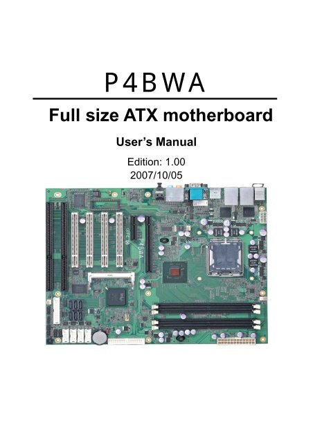
P4BWA Full size ATX motherboard
P4BWA Full size ATX motherboard
P4BWA Full size ATX motherboard

Create successful ePaper yourself
Turn your PDF publications into a flip-book with our unique Google optimized e-Paper software.
<strong>P4BWA</strong><br />
<strong>Full</strong> <strong>size</strong> <strong>ATX</strong> <strong>motherboard</strong><br />
User’s Manual<br />
Edition: 1.00<br />
2007/10/05
<strong>P4BWA</strong> User’s Manual<br />
Copyright<br />
Copyright 2007. All rights reserved. This document is copyrighted and all rights are<br />
reserved. The information in this document is subject to change without prior notice to make<br />
improvements to the products.<br />
This document contains proprietary information and protected by copyright. No part of this<br />
document may be reproduced, copied, or translated in any form or any means without prior<br />
written permission of the manufacturer.<br />
All trademarks and/or registered trademarks contains in this document are property of their<br />
respective owners.<br />
Disclaimer<br />
The company shall not be liable for any incidental or consequential damages resulting from<br />
the performance or use of this product.<br />
The company does not issue a warranty of any kind, express or implied, including without<br />
limitation implied warranties of merchantability or fitness for a particular purpose.<br />
The company has the right to revise the manual or include changes in the specifications of<br />
the product described within it at any time without notice and without obligation to notify any<br />
person of such revision or changes.<br />
Trademark<br />
All trademarks are the property of their respective holders.<br />
Any questions please visit our website at TUhttp://www.commell.com.twUT.<br />
-1-
<strong>P4BWA</strong> User’s Manual<br />
Packing List<br />
Please check package component before you use our products.<br />
Hardware:<br />
<strong>P4BWA</strong> <strong>Full</strong> <strong>size</strong> <strong>ATX</strong> <strong>motherboard</strong> x 1<br />
Cable Kit:<br />
Floppy flat cable x 1<br />
DB25 & DB9 cable x 1<br />
Serial ATA ribbon cable x 2<br />
I/O Shield x 1<br />
RAID driver Disk for Windows 2000,<br />
Windows XP and Windows Server 2003<br />
Other Accessories:<br />
Divers CD (including User’s Manual) x 1<br />
-2-
<strong>P4BWA</strong> User’s Manual<br />
Index<br />
Chapter1 ..................................................................... 6<br />
1.1 ................................................................................. 6<br />
1.2 ........................................................................... 7<br />
1.3 ........................................................................ 9<br />
1.4 .................................................................................... 10<br />
1.5 .......................................................................... 11<br />
Chapter 2 ......................................................... 12<br />
2.1 ............................................................................ 12<br />
2.2 ................................................................................ 13<br />
2.3 ......................................................................... 14<br />
2.3.1 ..............................................................14<br />
2.3.2 .............................................................14<br />
2.4 .................................................................... 15<br />
2.4.1 ...................................................................15<br />
2.4.2 ..............................................................16<br />
2.5 ...................................................................................... 17<br />
2.6 ......................................................................... 18<br />
2.7 ......................................................................... 19<br />
2.8 .............................................................................. 20<br />
2.9 .................................................................................. 21<br />
2.10 .............................................................................. 22<br />
2.11 ........................................................................... 24<br />
2.12 ................................................................................ 25<br />
2.13 .............................................................. 27<br />
2.14 ................................................................ 29<br />
2.15 ........................................................................................ 30<br />
2.16 ............................................................................ 32<br />
-3-
<strong>P4BWA</strong> User’s Manual<br />
2.17 ......................................................................... 33<br />
Chapter 3 ........................................... 35<br />
3.1 ............................................................................. 35<br />
3.2 .................................................................. 36<br />
3.3 ........................................................................... 40<br />
3.4 ......................................................................... 41<br />
Chapter 4 .................................................................... 43<br />
Appendix A ................................. 45<br />
A.1 ........................................................................................ 45<br />
A.2 .......................................................................................... 46<br />
A.3 ............................................................................................ 46<br />
A.4 ............................................................................................ 47<br />
A.5 ............................................................................................... 47<br />
A.6 ....................................................................................... 48<br />
A.7 ............................................................................................ 48<br />
Appedix B ................................................ 49<br />
Appedix C ................................................................... 53<br />
C.1 BIOS Auto Flash Tool ...................................................................... 53<br />
C.2 Flash Method................................................................................... 53<br />
Appendix D ........................................ 54<br />
Appendix E .................................. 55<br />
Contact Information .............................................................................. 56<br />
-4-
<strong>P4BWA</strong> User’s Manual<br />
(This page is left for blank)<br />
-5-
<strong>P4BWA</strong> User’s Manual<br />
Chapter1 <br />
1.1 <br />
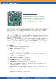
<strong>P4BWA</strong> is the <strong>motherboard</strong> with last Intel desktop technology with industrial <strong>motherboard</strong><br />
form factor. Based on Intel® Q965 and ICH8DO, the board integrates a new Core 2 Quad<br />
processor 775-pin socket, DDR2 memory slot, Intel® Graphic Media Accelerator 3000<br />
technology, PCI express interface and Serial ATA II with RAID function for a powerful<br />
desktop system.<br />
Intel® LGA775 processor<br />
The Intel® Core 2 Quad processor now comes with a new form factor with 775-pin PLGA<br />
package, for 533/800/1066MHz front-side-bus, 4MB L2 cache, and for 65nm manufacturing<br />
technology, the PLGA processor without pin header on solder side can make user installing<br />
the processor on the socket easier.<br />
Intel® Q965 and ICH8DO chipset<br />
The Intel Q965 integrates DDR2 533/667/800MHz for memory, and Graphic Media<br />
Accelerator (GMA) 3000 technology for new graphic engine. It can provide up to 256MB of<br />
frame buffer when you install over 512MB of system memory. The ICH8DO integrates with<br />
up to 10 USB2.0 interfaces (6 ports for <strong>P4BWA</strong>) I/O panel, and serial ATA II interface with<br />
RAID function.<br />
Dual Intel 82573L Gigabit LAN<br />
Dual Gigabit LAN with Intel 82573L, <strong>P4BWA</strong> comes with a powerful network function for the<br />
system that requires large transfer data of NAS system or Server platform.<br />
PCI-Express interface<br />
<strong>P4BWA</strong> integrates one x16 and x4 PCI-Express interface, it can provide up to 8GB/s of<br />
bandwidth, which AGP 8x can only provide up to 2GB/s.<br />
Multimedia interfaces<br />
<strong>P4BWA</strong> also integrates 7.1 channel HD audio, Mini-PCI, PCI and ISA interface, for these<br />
flexible function, system integrator can built more powerful systems for many applications.<br />
-6-
<strong>P4BWA</strong> User’s Manual<br />
1.2 <br />
General Specification<br />
Form Factor <strong>Full</strong> <strong>size</strong> <strong>ATX</strong> <strong>motherboard</strong><br />
CPU Intel® Core 2 Quad/Core 2 Duo/Pentium 4/Pentium D/<br />
Celeron D series processor with LGA775 socket<br />
Package type: PLGA 775<br />
Front side bus: 533/800/1066MT/s (133/200/266/QuadMHz x 4)<br />
Intel® Hyper-Threading Technology and Dual/Quad core<br />
supported, EM64T supported<br />
Memory<br />
4 x 240-pin DDR2 533/667/800MHz SDRAM up to 8GB<br />
Unbufferred, none-ECC memory supported only<br />
Chipset<br />
Intel® Q965 (Northbridge) and ICH8DO (Southbridge)<br />
BIOS<br />
Phoenix-Award v6.00PG 8Mb SPI flash BIOS<br />
Green Function Power saving mode includes doze, standby and suspend modes.<br />
ACPI version 1.0 and APM version 1.2 compliant<br />
Watchdog Timer System reset programmable watchdog timer with 1 ~ 255<br />
sec./min. of timeout value<br />
Real Time Clock Intel® ICH8DO built-in RTC with lithium battery<br />
Serial ATAII Intel® ICH8DO integrates 6 Serial ATA II interface<br />
RAID 0, 1,5,10 Intel Matrix Storage Technology supported<br />
Multi-I/O Port<br />
Chipset<br />
Serial Port<br />
USB Port<br />
Parallel Port<br />
Floppy Port<br />
IrDA Port<br />
K/B & Mouse<br />
GPIO<br />
Smart Fan<br />
VGA Display Interface<br />
Chipset<br />
Frame Buffer<br />
Connector<br />
Intel® 82801HDO(ICH8DO) with Winbond® W83627DHG and<br />
Fintek F81216D controller<br />
Five RS-232 and one RS232/422/485 serial ports<br />
Ten Hi-Speed USB 2.0 ports with 480Mbps of transfer rate<br />
One internal bi-direction parallel port with SPP/ECP/EPP mode<br />
One internal Floppy port<br />
One IrDA compliant Infrared interface supports SIR<br />
External PS/2 keyboard and mouse port on rear I/O<br />
One 12-pin Digital I/O connector with 8-bit programmable I/O<br />
interface<br />
One CPU fan connector for fan speed controllable<br />
Intel® Q965 GMA3000 (Graphic Memory Controller Hub)<br />
Up to 256MB shared with system memory<br />
External DB15 female connector on rear I/O<br />
-7-
<strong>P4BWA</strong> User’s Manual<br />
Ethernet Interface<br />
Controller Two Intel 82573L Gigabit Ethernet controller<br />
Type<br />
Triple speed 10/100/1000Base-T<br />
Auto-switching Fast Ethernet<br />
<strong>Full</strong> duplex, IEEE802.3U compliant<br />
Connector Two External RJ45 connectors with LED on rear I/O<br />
Audio Interface<br />
Chipset<br />
Intel integrated with Realtek ALC888 HD Audio<br />
Intel High Definition Audio compliance<br />
Interface<br />
7.1 channels sound output<br />
Connector<br />
External Audio phone jack for Line-out, Line-in, MIC-in, Surround,<br />
Center and Backsurround<br />
Onboard front audio connector with pin header<br />
Onboard CD-IN and external optical S/PDIF connector<br />
Expansive Interface<br />
PCI-Express One x16 PCI-Express slot (compatible with x1 slot)<br />
One x4 PCI-Express slot (compatible with x 1 slot)<br />
Up to 8GB/s of transfer bandwidth<br />
Power supply: +3.3V, +12V<br />
PCI<br />
Four-PCI slot (32-bit, 33MHz)<br />
Power supply: +3.3V, +5V, +12V, -12V<br />
Mini PCI<br />
One Mini-PCI socket TYPE III A (32-bit, 33MHz)<br />
Power supply: +3.3V, +5V, 3VSB<br />
ISA<br />
Two ISA slots (without DMA supported)<br />
Power and Environment<br />
Power Requirement Standard 24-pin <strong>ATX</strong> power supply (20-pin is compatible)<br />
Standard 8-pin 12v power Input connector (4-pin is compatible)<br />
Dimension 307mm x 244mm (L x W)<br />
Temperature Operating within 0 ~ 60 o C (32 ~ 140 o F)<br />
Storage within -20 ~ 85 o C (-4 ~ 185 o F)<br />
Ordering Code<br />
<strong>P4BWA</strong><br />
Support Intel Core 2 Quad LGA775 with DDRII, Onboard VGA, Dual<br />
Intel Gigabit LAN 10 x USB2.0, Realtek ALC888 HD Audio, 6 x<br />
COM Ports, GPIO, SATA and ISA slot<br />
For further product information please visit the website at http://www.commell.com.tw<br />
-8-
<strong>P4BWA</strong> User’s Manual<br />
1.3 <br />
DIMM<br />
Mini PCI<br />
PCI<br />
PCI-Express<br />
DOC<br />
ISA<br />
LAN<br />
Serial port<br />
PS2 USB VGA Audio SPDIF<br />
-9-
<strong>P4BWA</strong> User’s Manual<br />
1.4 <br />
Intel Core 2 Quad / Duo with 775 pin PLGA processor<br />
6.4GB/s<br />
Intel GMA3000 Graphics<br />
PCI-Express x16<br />
8GB/s<br />
Intel Q965<br />
4 x 240-pin DDR2<br />
533/667/800MHz<br />
up to 8GB<br />
2GB/s<br />
DMI<br />
SMBus 2.0<br />
300MB/s<br />
6 x Serial ATA II ports<br />
10 x USB2.0 ports<br />
ICH8DO<br />
2 x Intel<br />
82573L<br />
Mini-PCI slot<br />
HD Audio ALC888<br />
2 x Serial port<br />
W83627DHG<br />
SPI<br />
x4 & x16 PCI-Express<br />
1 x Floppy port<br />
F81216D<br />
4 x PCI bus<br />
8-bit GPIO<br />
2 x ISA bus<br />
1 x IrDA<br />
4 x serial port<br />
BIOS<br />
1 x Parallel Port<br />
KB/MS<br />
-10-
<strong>P4BWA</strong> User’s Manual<br />
1.5 <br />
“<br />
“<br />
“<br />
“<br />
“<br />
“<br />
“<br />
“<br />
“<br />
-11-
<strong>P4BWA</strong> User’s Manual<br />
Chapter 2 <br />
2.1 <br />
<strong>ATX</strong><br />
FDD<br />
JRTC<br />
COM Port 3~6<br />
CN_USB1/2<br />
CPUFAN<br />
JFRNT<br />
CN_DIO<br />
SATA II<br />
CN_AUDIO<br />
SYSFAN<br />
CN_LPT<br />
IrDA<br />
CN_12V<br />
NBFAN<br />
COM2<br />
CDIN<br />
CN_SMBUS JDOC<br />
-12-
<strong>P4BWA</strong> User’s Manual<br />
2.2 <br />
Jumper<br />
JRTC<br />
JDOC<br />
Function<br />
CMOS Operating/Clear Setting<br />
Setting address<br />
JRTC<br />
JDOC<br />
-13-
<strong>P4BWA</strong> User’s Manual<br />
2.3 <br />
2.3.1 <br />
Connector<br />
Function<br />
CPU<br />
PLGA775 CPU socket<br />
DDRII1/2/3/4 240 -pin DDR2 SDRAM DIMM socket<br />
S_ATAII1/2/3/4/5/6 7-pin Serial ATA II connector<br />
<strong>ATX</strong><br />
24-pin power supply connector<br />
CN_12V<br />
8-pin +12V additional power supply connector<br />
CN_AUDIO 5 x 2-pin audio connector<br />
CDIN<br />
4-pin CD-ROM audio input connector<br />
CN_DIO<br />
6 x 2-pin digital I/O connector<br />
CN_USB1/2 10-pin USB connector<br />
CPUFAN<br />
4-pin CPU cooler fan connector<br />
SYSFAN<br />
3-pin system cooler fan connector<br />
NBFAN<br />
3-pin Northbridge cooler fan connector<br />
CN_IR<br />
5-pin IrDA connector<br />
CN_SMBUS 5-pin I 2 C connector<br />
JFRNT<br />
14-pin front panel switch/indicator connector<br />
DOC<br />
32-pin DiskOnChip Socket<br />
FDD<br />
26-pin slim type floppy connector<br />
CN_COM2~6 5 x 2-pin com connector<br />
2.3.2 <br />
Connector<br />
Function<br />
VGA<br />
DB15 VGA connector<br />
USB<br />
Dual USB Ports<br />
COM<br />
DB9 Serial port connector<br />
PS2<br />
PS/2 Keyboard/Mouse connector<br />
AUDIO<br />
Audio connector<br />
USB_RJ45_A/B Quad USB and Dual RJ45 LAN connectors<br />
SPDIF<br />
Optical SPDIF digital audio output connector<br />
-14-
<strong>P4BWA</strong> User’s Manual<br />
2.4 <br />
2.4.1 <br />
<strong>P4BWA</strong> has a PLGA775 CPU socket onboard; please check following steps to install the<br />
processor properly.<br />
Attention<br />
Warring<br />
If <strong>P4BWA</strong> need RMA, please Keep CPU socket cover on the CPU Socket.<br />
If CPU Socket internal Pin damage, we could not provide warranty.<br />
1. Lift this bar<br />
Intel® Core 2 Quad/Duo processor<br />
Package type: 775 pin PLGA<br />
L2 Cache: 4MB<br />
FSB: 533/800/1066MT/S (266MHz x 4)<br />
Manufacturing: 65nm, 90nm<br />
Intel Hyper Threading Technology<br />
And Core 2 Quad/Core 2 Duo support<br />
Check point<br />
2. Uncover this plate<br />
3. Place the CPU on the top of<br />
the pins<br />
4. Lock this bar<br />
3. Cover this plate<br />
Notice: Please place the CPU on the pins tenderly to avoid bending the pins<br />
-15-
<strong>P4BWA</strong> User’s Manual<br />
2.4.2 <br />
<strong>P4BWA</strong> has four 240-pin DDR2 DIMM support up to 8GB of memory capacity. The memory<br />
frequency supports 533/667/800 MHz. Only Non-ECC memory is supported. Dual-Channel<br />
technology is supported while applying two modules with A+B channel.<br />
DDRII B2<br />
DDRII B1<br />
DDRII A2<br />
DDRII A1<br />
128-pin<br />
112-pin<br />
Please check the pin number to match the socket side well<br />
before installing memory module.<br />
-16-
<strong>P4BWA</strong> User’s Manual<br />
2.5 <br />
The board’s data of CMOS can be setting in BIOS. If the board refuses to boot due to<br />
inappropriate CMOS settings, here is how to proceed to clear (reset) the CMOS to its<br />
default values.<br />
Jumper: JRTC<br />
Type: Onboard 3-pin jumper<br />
JRTC Mode<br />
1-2 Clear CMOS<br />
2-3 Normal Operation<br />
Default setting<br />
3<br />
JRTC<br />
1<br />
-17-
<strong>P4BWA</strong> User’s Manual<br />
2.6 <br />
The board supports 32-pin DiskOnChip 2000. The onboard 32-pin socket, DOC, supports<br />
DiskOnChip2000 single chip flash disk in 32-pin DIP JEDEC with jumper selectable address<br />
on jumper JDOC.<br />
Jumper: JDOC<br />
Type: onboard 3-pin header<br />
3<br />
1<br />
JDOC<br />
DOC<br />
JDOC DiskOnChip Address<br />
1-2 D800h<br />
2-3 D000h<br />
Default setting<br />
-18-
<strong>P4BWA</strong> User’s Manual<br />
2.7 <br />
<strong>P4BWA</strong> has six Serial ATA II interfaces with RAID function, the transfer rate of the Serial<br />
ATA II can be up to 300MB/s. Please go to http://www.serialata.org/ for more about Serial<br />
ATA technology information. Based on Intel® ICH8DO, it supports Intel® Matrix Storage<br />
Technology with combination of RAID 0,1,5 and 10. The main features of RAID on<br />
ICH8DO are listed below:<br />
1. Supports for up to RAID volumes on a single, two-hard drive RAID array.<br />
2. Supports for two, six-hard drive RAID arrays on any of six Serial ATA ports.<br />
3. Supports for Serial ATA ATAPI devices.<br />
4. Supports for RAID spares and automatic rebuild.<br />
5. Supports on RAID arrays, including NCQ and native hot plug.<br />
For more information please visit Intel’s official website.<br />
For more about the system setup for Serial ATA, please check the chapter of SATA<br />
configuration.<br />
S_ATA1<br />
S ATA2<br />
S_ATA3<br />
S_ATA6<br />
S_ATA5<br />
S_ATA4<br />
(Associate accessory)<br />
-19-
<strong>P4BWA</strong> User’s Manual<br />
2.8 <br />
<strong>P4BWA</strong> has one 34-pin floppy interface, it supports use floppy and powering from onboard,<br />
please follow up the steps below to install the device.<br />
FDD<br />
-20-
<strong>P4BWA</strong> User’s Manual<br />
2.9 <br />
<strong>P4BWA</strong> integrates two Gigabit LAN interfaces with Dual Intel 82573L; they provide a<br />
standard IEEE 802.3 Ethernet interface for 1000BASE-T, 100BASE-TX and 10BASE-T<br />
applications. <strong>P4BWA</strong> provides two RJ45 connectors on the rear I/O panel.<br />
LAN<br />
-21-
<strong>P4BWA</strong> User’s Manual<br />
2.10 <br />
The board integrates onboard audio interface with REALTEK ALC888 codec, with Intel next<br />
generation of audio standard as High Definition Audio, it offers more vivid sound and other<br />
advantages than former AC97 audio compliance.<br />
The main specifications of ALC888 are:<br />
• High-performance DACs with 97dB S/N ratio<br />
• 10 DAC channels support 16/20/24-bit PCM format for 7.1 audio solution<br />
• 16/20/24-bit S/PDIF-OUT supports 44.1K/48K/96K/192KHz sample rate<br />
The board provides 7.1 channels audio phone jacks on rear I/O port, and Line-in/MIC-in<br />
ports for front I/O panel through optional cable.<br />
10<br />
9<br />
2 1<br />
CN_AUDIO<br />
Center<br />
Rear Speaker<br />
Side Speaker<br />
CDIN<br />
SPDIF<br />
LINE-IN<br />
LINE-OUT<br />
MIC-IN<br />
Rear I/O phone jacks<br />
-22-
<strong>P4BWA</strong> User’s Manual<br />
Connector: CN_AUDIO<br />
Type: 10-pin (2 x 5) header (pitch = 2.54mm)<br />
Pin Description Pin Description<br />
1 MIC_L 2 Ground<br />
3 MIC_R 4 ACZ_DET<br />
5 Front_R 6 MIC_JD<br />
7 Sense 8 N/C<br />
9 Front_L 10 Line_JD<br />
Connector: CDIN<br />
Type: 4-pin header (pitch = 2.54mm)<br />
Pin Description<br />
1 CD – Left<br />
2 Ground<br />
3 Ground<br />
4 CD – Right<br />
10 9<br />
2 2 1<br />
CN_AUDIO<br />
1<br />
CDIN<br />
-23-
<strong>P4BWA</strong> User’s Manual<br />
2.11 <br />
<strong>P4BWA</strong> integrates with Intel® Q965 GMCH for Intel Graphic Media Accelerator (GMA)<br />
3000 technology. It supports Intel® DVMT (Dynamic Video Memory Technology) 3.0 for up<br />
to 256MB frame buffer <strong>size</strong> shared with system memory. With a 400MHz core and DirectX 9<br />
and OpenGL acceleration, <strong>P4BWA</strong> provides the powerful onboard graphics interface<br />
without additional graphic card. (More information please visit Intel’s website)<br />
For more information of configuring the frame buffer <strong>size</strong>, please check the chapter of video<br />
memory configuration.<br />
Intel Q965 GMCH<br />
VGA (DB15)<br />
-24-
<strong>P4BWA</strong> User’s Manual<br />
2.12 <br />
<strong>P4BWA</strong> integrates 10 USB2.0 ports. The specifications USB2.0 are listed below:<br />
Interface<br />
Controller<br />
Transfer Rate<br />
USB2.0<br />
Intel ICH8DO<br />
Up to 480Mb/s<br />
The Intel® ICH8DO contains and Enhanced Host Controller Interface (EHCI) and six<br />
Universal Host Controller Interfaces (UHCI), it can determine whether your connected<br />
device is for USB1.1 or USB2.0, and change the transfer rate automatically.<br />
USB<br />
-25-
<strong>P4BWA</strong> User’s Manual<br />
Connector: CN_USB1/2<br />
Type: 10-pin (5 x 2) header for USB1/2 Ports<br />
Pin Description Pin Description<br />
1 VCC 2 VCC<br />
3 Data0- 4 Data1-<br />
5 Data0+ 6 Data1+<br />
7 Ground 8 Ground<br />
9 Ground 10 N/C<br />
10<br />
9<br />
2<br />
1<br />
CN_USB1/2<br />
-26-
<strong>P4BWA</strong> User’s Manual<br />
2.13 <br />
The <strong>P4BWA</strong> provides a standard <strong>ATX</strong> power supply with 24-pin <strong>ATX</strong> connector and<br />
additional 12V connector, and the board provides one 4-pin fan connectors supporting<br />
smart fan for CPU cooler and two 3-pin cooler fan connectors for system and Northbridge<br />
chip. The 8-pin additional power connector is necessary for CPU powering; please connect<br />
this well before you finishing the system setup.<br />
1 12<br />
13 24<br />
<strong>ATX</strong><br />
1 4<br />
CPUFAN<br />
3<br />
1<br />
SYSFAN<br />
4<br />
8<br />
1<br />
5<br />
CN_12V<br />
1<br />
3<br />
1<br />
NBFAN<br />
-27-
<strong>P4BWA</strong> User’s Manual<br />
Connector: <strong>ATX</strong><br />
Type: 24-pin <strong>ATX</strong> power connector<br />
PIN assignment<br />
1 3.3V 13 3.3V<br />
2 3.3V 14 -12V<br />
3 GND 15 GND<br />
4 5V 16 PS_ON<br />
5 GND 17 GND<br />
6 5V 18 GND<br />
7 GND 19 GND<br />
8 PW_OK 20 -5V<br />
9 5V_SB 21 5V<br />
10 12V 22 5V<br />
11 12V 23 5V<br />
12 3.3V 24 GND<br />
Connector: CN_12V<br />
Type: 8-pin standard Pentium 4 additional +12V power connector<br />
Pin Description Pin Description<br />
1 Ground 5 +12V<br />
2 Ground 6 +12V<br />
3 Ground 7 +12V<br />
4 Ground 8 +12V<br />
Connector: CPUFAN<br />
Type: 4-pin fan wafer connector<br />
Pin Description Pin Description<br />
1 Ground 2 +12V<br />
3 Fan Speed Detection 4 Sense<br />
Connector: NBFAN, SYSFAN<br />
Type: 3-pin fan wafer connector<br />
Pin Description Pin Description Pin Description<br />
1 Ground 2 +12V 3 Sense<br />
-28-
<strong>P4BWA</strong> User’s Manual<br />
2.14 <br />
The board provides a programmable 8-bit digital I/O interface, and one SMBus (System<br />
management bus) interface for control panel application.<br />
Connector: CN_DIO<br />
Type: onboard 2 x 6-pin header, pitch=2.0mm<br />
Pin Description Pin Description<br />
1 Ground 2 Ground<br />
3 GP10 4 GP14<br />
5 GP11 6 GP15<br />
7 GP12 8 GP16<br />
9 GP13 10 GP17<br />
11 VCC 12 +12V<br />
12<br />
11<br />
CN_DIO<br />
2<br />
1<br />
Connector: CN_SMBUS<br />
Type: 5-pin 2.54-pitch header<br />
Pin Description<br />
1 VCC<br />
2 N/C<br />
3 SMBDATA<br />
4 SMBCLK<br />
5 Ground<br />
SMBUS<br />
-29-
<strong>P4BWA</strong> User’s Manual<br />
2.15 <br />
The board supports one RS232 serial port and one jumper selectable RS232/422/485 serial<br />
ports. The jumper JCSEL1 & JCSEL2 can let you configure the communicating modes for<br />
COM2.<br />
Connector: CN_COM2<br />
Type: 10-pin (5 x 2) 2.54mm x 2.54mm-pitch box header for COM2<br />
Pin Description Pin Description<br />
1 DCD/422RX-/485- 2 RXD/422RX+/485+<br />
3 TXD/422TX+ 4 DTR/422TX-<br />
5 GND 6 DSR<br />
7 RTS 8 CTS<br />
9 RI 10 N/C<br />
2<br />
1<br />
10<br />
9<br />
CN_COM 2<br />
-30-
<strong>P4BWA</strong> User’s Manual<br />
SIR<br />
RS-422<br />
RS-485<br />
RS-232<br />
JCSEL1<br />
2 8<br />
1 7<br />
JCSEL2<br />
2 12<br />
1<br />
11<br />
JCSEL2<br />
JCSEL1<br />
-31-
<strong>P4BWA</strong> User’s Manual<br />
2.16 <br />
The JFRNT provides front control panel of the board, such as power button, reset and<br />
beeper, etc. Please check well before you connecting the cables on the chassis.<br />
Connector: JFRNT<br />
Type: onboard 14-pin (2 x 7) 2.54-pitch header<br />
Function Signal PIN Signal Function<br />
IDE LED<br />
Reset<br />
Power<br />
HDLED+ 1 2 PWDLED+<br />
HDLED- 3 4 N/C<br />
Reset+ 5 6 PWDLED-<br />
Reset- 7 8 SPKIN+<br />
N/C 9 10 N/C<br />
PWRBT+ 11 12 N/C<br />
Power<br />
LED<br />
Speaker<br />
Button PWRBT- 13 14 SPKIN-<br />
14 13<br />
JFRNT<br />
2<br />
1<br />
-32-
<strong>P4BWA</strong> User’s Manual<br />
2.17 <br />
<strong>P4BWA</strong> has one x16 and x4 PCI-Express slot. PCI-Express is the last expansion interface<br />
technology, for its serial data transfer scheme, each lane will be up to 500MB/s (duplex),<br />
and the x16 (16 lanes) can be up to 8GB/s more than 2GB/s as AGP 8x bus transfer rate.<br />
The x4 slot can be also for x1 compatible use.<br />
PCIE (PCI-Express x16 slot)<br />
PCIE (PCI-Express x4 slot)<br />
-33-
<strong>P4BWA</strong> User’s Manual<br />
(This page is left for blank)<br />
-34-
<strong>P4BWA</strong> User’s Manual<br />
Chapter 3 <br />
3.1 <br />
SATA Mode:<br />
This option can let you select whether the Serial ATA hard drives would work under normal<br />
IDE mode or RAID mode. The RAID mode need more than one HDD is applied.<br />
-35-
<strong>P4BWA</strong> User’s Manual<br />
3.2 <br />
The board integrates Intel® ICH8DO with RAID function for Serial ATA II drives, and<br />
supports the configurations below:<br />
RAID 0 (Stripping): Two hard drives operating as one drive for optimized data R/W<br />
performance. It needs two unused drives to build this operation.<br />
RAID 1 (Mirroring): Copies the data from first drive to second drive for data security, and if<br />
one drive fails, the system would access the applications to the workable drive. It needs two<br />
unused drives or one used and one unused drive to build this operation. The second drive<br />
must be the same or lager <strong>size</strong> than first one.<br />
RAID 5 (striping with parity)<br />
A RAID 5 array contains three or more hard drives where the data is divided into<br />
manageable blocks called strips. Parity is a mathematical method for recreating data that<br />
was lost from a single drive, which increases fault-tolerance. The data and parity are striped<br />
across all the hard drives in the array. The parity is striped in a rotating sequence to reduce<br />
bottlenecks associated with the parity calculations.<br />
RAID 10 (RAID 0+1)<br />
A RAID 10 array uses four hard drives to create a combination of RAID levels 0 and 1. The<br />
data is striped across a two-drive array forming the RAID 0 component. Each of the drives<br />
in the RAID 0 array is then mirrored by a RAID 1 component.<br />
Intel Matrix Storage Technology: This technology would allow you to use RAID 0+1 mode<br />
on only two drives (4 drives needed on traditional RAID 0+1). It will create two partitions on<br />
each hard drive to simulate RAID 0 and RAID 1. It also can let you modify the partition <strong>size</strong><br />
without re-formatted.<br />
For more information of Intel Matrix Storage Technology, please visit Intel’s website.<br />
If you need to install an operation system on the RAID set, please use the driver disk<br />
attached in the package when it informs you to obtain the RAID drivers.<br />
-36-
<strong>P4BWA</strong> User’s Manual<br />
Please press to enter the RAID configuration menu.<br />
You can setup the RAID under operation system for Microsoft® Windows XP SP1 or<br />
Windows 2000 SP4 version, please install the Intel® Application Accelerator Ver.4.5 later to<br />
support RAID configuration with Intel® Matrix Storage Technology.<br />
1. After installing Intel Application Accelerator, please execute Intel® Storage Utility.<br />
Demo configuration for 2 SATA Drives and<br />
set as Intel Matrix Storage Technology set<br />
-37-
<strong>P4BWA</strong> User’s Manual<br />
2. Select Actions to Create RAID Volume<br />
Rename the Volume name<br />
Select RAID Level as 0<br />
Left as default<br />
-38-
<strong>P4BWA</strong> User’s Manual<br />
3. Please select two hard drives to prepare to set the RAID volume<br />
4. Specify the Volume <strong>size</strong><br />
Tune this bar to specify<br />
the volume <strong>size</strong>, if you<br />
specify the volume <strong>size</strong><br />
lower than maximum,<br />
you can create a second<br />
volume for another<br />
RAID set.<br />
(Make RAID 0+1 on only<br />
two hard drives)<br />
5. Repeat the step 1 to create second volume as RAID Level 1.<br />
For other configuration set please click Help on tool bar.<br />
-39-
<strong>P4BWA</strong> User’s Manual<br />
3.3 <br />
The board integrates Intel® ICH8DO with REALTEK® ALC888codec. It can support<br />
7.1channel sound under system configuration. Please follow the steps below to setup your<br />
sound system.<br />
1. Install REALTEK AC97 Audio driver.<br />
2. Lunch the control panel and Sound Effect Manager.<br />
3. Select Speaker Configuration<br />
4. Select the sound mode to meet your speaker system.<br />
-40-
<strong>P4BWA</strong> User’s Manual<br />
3.4 <br />
Based on Intel® Q965 chipset with GMA (Graphic Media Accelerator) 3000, the board<br />
supports Intel® DVMT (Dynamic Video Memory Technology) 3.0, which would allow the<br />
video memory be triggered up to 256MB.<br />
To support DVMT, you need to install the Intel GMA 3000 Driver with supported OS.<br />
BIOS Setup:<br />
On-Chip Video Memory Size: This option combines three items below for setup.<br />
On-Chip Frame Buffer Size:<br />
This item can let you select video memory which been allocated for legacy VGA and SVGA<br />
graphics support and compatibility. The available option is 1MB and 8MB.<br />
Fixed Memory Size:<br />
This item can let you select a static amount of page-locked graphics memory which will be<br />
allocated during driver initialization. Once you select the memory amount, it will be no<br />
longer available for system memory.<br />
DVMT Memory Size:<br />
This item can let you select a maximum <strong>size</strong> of dynamic amount usage of video memory,<br />
the system would configure the video memory depends on your application, this item is<br />
-41-
<strong>P4BWA</strong> User’s Manual<br />
strongly recommend to be selected as MAX DVMT.<br />
Fixed + DVMT Memory Size:<br />
You can select the fixed amount and the DVMT amount at the same time for a guaranteed<br />
video memory and additional dynamic video memory, please check the table below for<br />
available setting.<br />
System<br />
Memory<br />
256MB ~ 511MB<br />
512MB~1023MB<br />
Notice:<br />
On-Chip<br />
Frame<br />
Buffer Size<br />
Fixed<br />
Memory<br />
Size<br />
DVMT<br />
Memory<br />
Size<br />
Total<br />
Graphic<br />
Memory<br />
1MB 128MB 0MB 128MB<br />
1MB 0MB 128MB 128MB<br />
8MB 128MB 0MB 128MB<br />
8MB 0 128MB 128MB<br />
1MB 128MB 0 128MB<br />
1MB 256MB 0 256MB<br />
1MB 0 128MB 128MB<br />
1MB 0 256MB 256MB<br />
8MB 128MB 0 128MB<br />
8MB 256MB 0 256MB<br />
8MB 0 128MB 128MB<br />
8MB 0 256MB 256MB<br />
1. The On-Chip Frame Buffer Size would be included in the Fixed Memory.<br />
Please select the memory <strong>size</strong> according to this table<br />
-42-
<strong>P4BWA</strong> User’s Manual<br />
Chapter 4 <br />
The <strong>motherboard</strong> uses the Award BIOS for the system configuration. The Award<br />
BIOS in the single board computer is a customized version of the industrial standard<br />
BIOS for IBM PC AT-compatible computers. It supports Intel x86 and compatible CPU<br />
architecture based processors and computers. The BIOS provides critical low-level<br />
support for the system central processing, memory and I/O sub-systems.<br />
The BIOS setup program of the single board computer let the customers modify the<br />
basic configuration setting. The settings are stored in a dedicated battery-backed<br />
memory, NVRAM, retains the information when the power is turned off. If the battery<br />
runs out of the power, then the settings of BIOS will come back to the default setting.<br />
The BIOS section of the manual is subject to change without notice and is provided here<br />
for reference purpose only. The settings and configurations of the BIOS are current at<br />
the time of print, and therefore they may not be exactly the same as that displayed on<br />
your screen.<br />
To activate CMOS Setup program, press key immediately after you turn on<br />
the system. The following message “Press DEL to enter SETUP” should appear in the<br />
lower left hand corner of your screen. When you enter the CMOS Setup Utility, the Main<br />
Menu will be displayed as Figure 4-1. You can use arrow keys to select your function,<br />
press key to accept the selection and enter the sub-menu.<br />
Figure 4-1 CMOS Setup Utility Main Screen<br />
-43-
<strong>P4BWA</strong> User’s Manual<br />
(This page is left for blank)<br />
-44-
<strong>P4BWA</strong> User’s Manual<br />
Appendix A <br />
A.1 <br />
Connector: FDD<br />
Type: 34-pin (2 x 17) 2.54-pitch box header<br />
33<br />
34<br />
1<br />
2<br />
Pin Description Pin Description<br />
1 Ground 2 DRIVE DENSITY SELECT 0<br />
3 Ground 4 DRIVE DENSITY SELECT 1<br />
5 Ground 6 N/C<br />
7 Ground 8 INDEX-<br />
9 Ground 10 MOTOR ENABLE A-<br />
11 Ground 12 DRIVER SELECT B-<br />
13 Ground 14 DRIVER SELECT A-<br />
15 Ground 16 MOTOR ENABLE B-<br />
17 Ground 18 DIRECTION-<br />
19 Ground 20 STEP-<br />
21 Ground 22 WRITE DATA-<br />
23 Ground 24 WRITE GATE-<br />
25 Ground 26 TRACK 0-<br />
27 Ground 28 WRITE PROTECT-<br />
29 Ground 30 READ DATA-<br />
31 Ground 32 HEAD SELECT-<br />
33 Ground 34 DISK CHANGE-<br />
-45-
<strong>P4BWA</strong> User’s Manual<br />
A.2 <br />
Connector: COM1<br />
Type: 9-pin D-sub male connector on I/O Panel<br />
Pin Description Pin Description<br />
1 DCD 6 DSR<br />
2 SIN 7 RTS<br />
3 SO 8 CTS<br />
4 DTR 9 RI<br />
5 Ground<br />
1<br />
2<br />
3<br />
4<br />
5<br />
6<br />
7<br />
8<br />
9<br />
Connector: COM2/3/4/5/6<br />
Type: 10-pin (2x5) 2.54-pitch box header<br />
10<br />
9<br />
2 1<br />
Pin Description Pin Description<br />
1 DCD- 6 DSR-<br />
2 SIN- 7 RTS-<br />
3 SO- 8 CTS-<br />
4 DTR- 9 RI<br />
5 Ground 10 N/C<br />
A.3 <br />
6<br />
1 11<br />
2 12<br />
Connector: VGA<br />
3 13<br />
Type: 15-pin D-sub female connector on I/O Panel 4 14<br />
5 15<br />
10<br />
Pin Description Pin Description Pin Description<br />
1 RED 6 Ground 11 N/C<br />
2 GREEN 7 Ground 12 5VCDA<br />
3 BLUE 8 Ground 13 HSYNC<br />
4 N/C 9 LVGA5V 14 VSYNC<br />
5 Ground 10 Ground 15 5VCLK<br />
-46-
<strong>P4BWA</strong> User’s Manual<br />
A.4 <br />
Connector: RJ45<br />
Type: RJ45 connector with LED on I/O Panel<br />
Pin 1 2 3 4 5<br />
Description TRD0+ TRD0- TRD1+ TRD1-<br />
NC<br />
Pin 6 7 8 9 10<br />
Description NC TRD2+ TRD2- TRD3+ TRD3-<br />
A.5 <br />
Connector: CN_SMBUS<br />
Type: 5-pin SMBus (1x5)2.54 pitch header<br />
Pin Description Pin Description<br />
1 VCC 2 N/C<br />
3 SMBDATA 4 SMBCLK<br />
5 Ground<br />
5<br />
1<br />
-47-
<strong>P4BWA</strong> User’s Manual<br />
A.6 <br />
Connector: LPT (PRINTER)<br />
Type: 26-pin (2 x 13) 2.54-pitch box header<br />
14 26<br />
13<br />
1<br />
Pin Description Pin Description<br />
1 STROBE- 14 AUTO FEED-<br />
2 D0 15 ERROR-<br />
3 D1 16 INITIALIZE-<br />
4 D2 17 SELECT INPUT-<br />
5 D3 18 Ground<br />
6 D4 19 Ground<br />
7 D5 20 Ground<br />
8 D6 21 Ground<br />
9 D7 22 Ground<br />
10 ACKNOWLEDGE- 23 Ground<br />
11 BUSY 24 Ground<br />
12 PAPER EMPTY 25 Ground<br />
13 SELECT+ 26 N/C<br />
A.7 <br />
Connector: CN_IR<br />
Type: 5-pin header for SIR Port<br />
5<br />
1<br />
Pin Description<br />
1 Vcc<br />
2 N/C<br />
3 IRRX<br />
4 Ground<br />
5 IRTX<br />
-48-
<strong>P4BWA</strong> User’s Manual<br />
Appedix B <br />
B1. <br />
-49-
<strong>P4BWA</strong> User’s Manual<br />
-50-
<strong>P4BWA</strong> User’s Manual<br />
B2. <br />
-51-
<strong>P4BWA</strong> User’s Manual<br />
B3. <br />
IRQ :<br />
-52-
<strong>P4BWA</strong> User’s Manual<br />
Appedix C <br />
C.1 BIOS Auto Flash Tool<br />
The board is based on Award BIOS and can be updated easily by the BIOS auto flash<br />
tool. You can download the tool online at the address below:<br />
TUhttp://www.award.comUT<br />
TUhttp://www.commell.com.tw/support/support.htmUT<br />
File name of the tool is “awdflash.exe”, it’s the utility that can write the data into the BIOS<br />
flash ship and update the BIOS.<br />
C.2 Flash Method<br />
1. Please make a bootable floppy disk.<br />
2. Get the last .bin files you want to update and copy it into the disk.<br />
3. Copy awardflash.exe to the disk.<br />
4. Power on the system and flash the BIOS. (Example: C:/ awardflash XXX.bin)<br />
5. Re-star the system.<br />
Any question about the BIOS re-flash please contact your distributors or visit the<br />
web-site at below:<br />
http://www.commell.com.tw/support/support.htm<br />
-53-
<strong>P4BWA</strong> User’s Manual<br />
Appendix D <br />
The GPIO can be programmed with the MSDOS debug program using simple<br />
IN/OUT commands.The following lines show an example how to do this.<br />
GPIO0…..GPIO7 bit0……bit7<br />
-o 4E 87 ;enter configuration<br />
-o 4E 87<br />
-o 4E 07<br />
-o 4F 09 ;enale GPIO function<br />
-o 4E 30<br />
-o 4F 02 ;enable GPIO configuration<br />
-o 4E F0<br />
-o 4F xx ;set GPIO as input/output; set ‘1’ for input,’0’for<br />
output<br />
-o 4E F1<br />
-o 4F xx ;if set GPIO’s as output,in this register its value can<br />
be set<br />
Optional :<br />
-o 4E F2<br />
-o 4F xx ; Data inversion register ; ‘1’ inverts the current valus<br />
of the bits ,’0’ leaves them as they are<br />
-o 4E 30<br />
-o 4F 01 ; active GPIO’s<br />
For further information, please refer to Winbond W83627DHG datasheet.<br />
-54-
<strong>P4BWA</strong> User’s Manual<br />
Appendix E <br />
The watchdog timer makes the system auto-reset while it stops to work for a period. The<br />
integrated watchdog timer can be setup as system reset mode by program.<br />
Timeout Value Range<br />
- 1 to 255<br />
- Second or Minute<br />
Program Sample<br />
Watchdog timer setup as system reset with 5 second of timeout<br />
-o 4E, 87<br />
-o 4E, 87<br />
-o 4E, 07<br />
-o 4F, 08 Logical Device 8<br />
-o 4E, 30 Activate<br />
-o 4F, 01<br />
-o 4E, F5 Set as Second*<br />
-o 4F, 00<br />
-o 4E, F6 Set as 5<br />
-o 4F, 05<br />
* Minute: bit 3 = 0; Second: bit 3 = 1<br />
You can select Timer setting in the BIOS, after setting the time options, the system will<br />
reset according to the period of your selection.<br />
-55-
<strong>P4BWA</strong> User’s Manual<br />
Contact Information<br />
Any advice or comment about our products and service, or anything<br />
we can help you please don’t hesitate to contact with us. We will do<br />
our best to support you for your products, projects and business.<br />
Taiwan Commate Computer Inc.<br />
Address<br />
8F, No. 94, Sec. 1, Shin Tai Wu Rd., Shi Chih<br />
Taipei Hsien, Taiwan<br />
TEL +886-2-26963909<br />
FAX +886-2-26963911<br />
Website<br />
E-Mail<br />
TUhttp://www.commell.com.twUT<br />
TUinfo@commell.com.twUT (General Information)<br />
TUtech@commell.com.twUT (Technical Support)<br />
Commell is our trademark of industrial PC division<br />
-56-