Owners Manual - Spinning® Computer - Star Trac Support
Owners Manual - Spinning® Computer - Star Trac Support
Owners Manual - Spinning® Computer - Star Trac Support

Create successful ePaper yourself
Turn your PDF publications into a flip-book with our unique Google optimized e-Paper software.
Spinning ®<br />
<strong>Computer</strong><br />
User <strong>Manual</strong><br />
Installation, Service and Instructor Education
Table of Contents<br />
01<br />
02<br />
03<br />
05<br />
06<br />
07<br />
08<br />
10<br />
11<br />
12<br />
15<br />
18<br />
19<br />
20<br />
21<br />
22<br />
23<br />
25<br />
FCC Regulatory Statements<br />
Parts List<br />
Marketing Statement Regarding Heart Rate<br />
Specifications<br />
How it Works<br />
<strong>Computer</strong> Window and Buttons<br />
Installing or Replacing Batteries<br />
Do I need to Re-sync?<br />
Testing for RPM<br />
Syncing Mode<br />
Setup Mode<br />
Installation of Cadence Sensor and Magnet – All Spinners ®<br />
Mounting <strong>Computer</strong> On Handlebars - Spinner ® V<br />
Mounting <strong>Computer</strong> On Handlebars - Spinner ® Sport / Fit / Velo<br />
Mounting <strong>Computer</strong> On Handlebars - Pro 7070 / Elite 7080 / NXT 7090<br />
Maintenance Checklist<br />
FAQs and Troubleshooting<br />
Spinning ® Instructor Education
FCC Regulatory Statements<br />
1. This device complies with Part 15 of the FCC Rules. Operation is subject to the following two<br />
conditions: (1) this device may not cause harmful interference, and (2) this device must accept<br />
any interference received, including interference that may cause undesired operation.<br />
2. Changes or modifications not expressly approved by <strong>Star</strong> <strong>Trac</strong> could void the user’s authority to<br />
operate the equipment.<br />
1
Parts List<br />
Part Number for<br />
re-order<br />
727-0100 Spinning ®<br />
<strong>Computer</strong> Kit<br />
727-0093-KT Mounting<br />
Bracket Kit<br />
Quantity Description<br />
1 Spinning ® <strong>Computer</strong><br />
1 Mounting Bracket<br />
1 Spinner ® V Mounting Bracket Insert<br />
1 Mounting Insert for open handlebars<br />
727-0101-KT 1 Cadence Sensor<br />
727-0094 1 Cadence Magnet<br />
N/A 1 AA Panasonic Batteries<br />
N/A 1 Spinning ® <strong>Computer</strong> <strong>Manual</strong><br />
N/A 1 5 mm Allen Assembly Tool<br />
N/A 1 2 mm Allen Assembly Tool<br />
N/A 1 M6x30 <strong>Computer</strong> Clamp Screw for Rhino Horn<br />
Before installing the Spinning ® <strong>Computer</strong>, verify that all the parts needed for mounting onto bikes are<br />
included. If any of the items are missing, call <strong>Star</strong> <strong>Trac</strong> at 800-503-1221 or 714-669-1660 to order a<br />
replacement kit.<br />
2
Marketing Statement Regarding Heart Rate<br />
Marketing Statement Regarding Heart Rate Acquisition on the <strong>Star</strong> <strong>Trac</strong> Spinning ® <strong>Computer</strong>:<br />
<strong>Star</strong> <strong>Trac</strong> takes the acquisition and accuracy of heart rate very seriously and has developed a system to perform<br />
to the best ability that technology will allow. <strong>Star</strong> <strong>Trac</strong> has engineered a product that has taken every precaution<br />
possible to acquire an accurate heart rate signal as well as eliminate “crosstalk” interference that may be<br />
caused by other monitors being placed too close together.<br />
To achieve the best possible results from your Spinning ® <strong>Computer</strong>, please abide by the following important<br />
parameters:<br />
1) Users must wear either a Coded Transmitter (such as Polar© T61, Polar© T31C or Polar© WearLink ® )<br />
or an Ant+ compatible transmitter when operating the Spinner ® bike with the Spinning ® <strong>Computer</strong>. Only<br />
the listed transmitters allow a “one to one” relationship with the Spinning ® <strong>Computer</strong> and will minimize<br />
potential “crosstalk” interference. If users wear non-coded straps, there is significantly increased potential for<br />
“crosstalk” which will cause erratic heart rate display, loss of heart rate display and significantly reduce the<br />
consistency of accurate heart rate reporting.<br />
2) Bikes should be spaced so that the side-to-side distance from the Spinning ® <strong>Computer</strong> on one bike and the<br />
Spinning ® <strong>Computer</strong> on bikes to the left or right is at least 36 inches (91.4 cm). In addition, the distance from<br />
the bottom of the Spinning ® <strong>Computer</strong> on one bike to the seat of the bike in front of it (where another rider<br />
and his her transmitter would be seated) should be at least 24 inches (61 cm) in order to significantly reduce<br />
chances for interference. See the diagram on page 5 regarding bike layout.<br />
3
3) In order for the computer to display the user’s heart rate,<br />
the rider must lean into the display within 10” (25 cm) during<br />
the first 30 seconds of the ride and wait for the HR to display.<br />
During this time the Heart Rate icon is rapidly blinking (2 x<br />
per second), showing that the computer is actively searching<br />
for a wireless heart rate. Once a heart rate has been found<br />
the heart rate value is displayed and the HR icon changes to<br />
a slow blink (1 x per second) If no heart rate is found after<br />
30 seconds the console stops searching and no HR will be<br />
displayed.<br />
4) Calorie calculations are displayed as a summary only.<br />
5) Cell phones, televisions, speakers and other electronic<br />
devices can cause interference with the operation if they<br />
are in close proximity to the Spinning ® <strong>Computer</strong> and/or<br />
transmitter.<br />
If there are any questions regarding operation or usage of<br />
the Spinning ® <strong>Computer</strong>, please contact <strong>Star</strong> <strong>Trac</strong> Customer<br />
<strong>Support</strong> at 800-503-1221 or 714-669-1660.<br />
4
Specifications<br />
<strong>Computer</strong>:<br />
Heart Rate Range:<br />
Battery:<br />
Battery life expectancy:<br />
Approximately 25”- 30” (63 cm - 76 cm) from computer to users HR chest strap<br />
Qty. 4 AA Alkaline<br />
1 year (depending on use and backlight usage)<br />
Cadence Sensor:<br />
Battery:<br />
Battery life expectancy:<br />
Distance to magnet:<br />
Lithium CR2032<br />
Approximately 1 year in a commercial environment (depending on use)<br />
Approximately 5mm<br />
At least 36<br />
inches (91.4 cm)<br />
At least 24<br />
inches (61 cm)<br />
5
How it Works<br />
How does the Spinning ® computer work?<br />
The Spinning ® computer displays heart rate, RPM (speed), total distance and elapsed time.<br />
• The heart rate (HR) information is received from an Ant+ or Polar ® compatible heart rate strap worn by<br />
the person riding the Spinning ® Bike. The HR strap sends a radio signal to the computer and the computer<br />
displays the person’s heart rate. If any other strap is used it will not display the heart rate. The computer and<br />
heart rate strap must be within range of each other and no other heart rate strap can be within this imaginary<br />
circle. The range is approximately 25”- 30” (63 cm - 76 cm) from the computer.<br />
•The RPM signal is transmitted by the cadence sensor sending the RPM to the computer. Each time the<br />
magnet on the flywheel passes the cadence sensor it records one revolution and sends this number to<br />
the computer.<br />
RPM<br />
Heart Rate<br />
6
<strong>Computer</strong> Window and Buttons<br />
<strong>Star</strong>t pedaling then press any button to turn on the Spinning ® <strong>Computer</strong>; the following data<br />
will be displayed:<br />
HR- Displays the Heart Rate of the user when wearing a compatible HR telemetry strap in beats<br />
per minute.<br />
RPM- Shows the pedaling speed of the user in revolutions per minute.<br />
Total Distance- Distance measured in miles or kilometers depending on the setup selection.<br />
Elapsed Time – The length of time in minutes from the time the computer has been activated or reset.<br />
Buttons:<br />
Toggle (right) button - Toggles between: Total Distance<br />
and Elapsed Time.<br />
Light (left) button - Turns on the backlight to enable<br />
viewing in low light settings.<br />
7
Installing or Replacing Console Batteries<br />
Time required:<br />
• 5 Minutes<br />
Parts required:<br />
• 4 new AA alkaline batteries<br />
Tools required:<br />
• Slotted or Phillips screwdriver<br />
Low Battery<br />
Indicator<br />
NOTE: The batteries in the computer will last approximately<br />
1 year depending on usage. The cadence sensor battery will<br />
last approximately 1 year.<br />
1. Remove the computer from the handlebar or computer mounting bracket.<br />
2. Loosen the captive screw on the back of the battery cover (screw will not<br />
completely come off, it will remain captive.) To remove the cover, pull on the<br />
captive screw and lift.<br />
3. Install 4 new batteries.<br />
NOTE: Replace all 4 batteries at the same time.<br />
8
Installing or Replacing Batteries – continued<br />
4. Note the directions each battery is to be installed. There is a plus (+) and minus (-) symbol inside the<br />
battery compartment. The + sign indicates the positive (+) side on the battery and the - indicates the<br />
negative (-) side on the battery.<br />
5. Insert each of the 4 batteries into the battery compartment of the computer.<br />
6. Attach the battery cover and tighten the screw.<br />
7. Attach the computer onto the handlebar or computer mounting bracket and test.<br />
9
Do I need to Re-sync?<br />
NOTE: Syncing will not improve heart rate and is not a calibration; it should only be used to Sync (Pair up) the<br />
cadence sensor and the computer so that RPM can be transmitted.<br />
Perform the Syncing process after checking all of the following:<br />
• Is the battery secure in the cadence sensor and the cover tight?<br />
o A loose battery will prevent the cadence sensor from transmitting<br />
the RPM signal to the computer.<br />
• Is the magnet aligned with the cadence sensor?<br />
o A missing magnet or one that is not lined up properly will prevent the<br />
cadence sensor from transmiting the RPM signal to the computer.<br />
o The cadense sensor LED will blink for the first few revolutions at start up. If<br />
the LED does not blink, check the magnet alignment before changing the batteries.<br />
• Does the computer turn on when you press a button?<br />
o If the computer does not turn on, replace the batteries in the computer.<br />
• The computer turns on but as you pedal it does not show the RPM.<br />
o If you have performed all of the above steps, you may now sync the computer and cadence sensor.<br />
This will make them a paired set and will be able to transmit and receive the RPM signal.<br />
10
Testing for RPM<br />
Time required:<br />
• Less than 5 Minutes<br />
Parts required:<br />
• N/A<br />
Tools required:<br />
• N/A<br />
TEST Procedure:<br />
1. Once the batteries are installed, press any button and the display window will turn on in the<br />
Workout Mode.<br />
2. Test by waving a magnet across the cadence sensor. If you see RPM<br />
values, then the cadence sensor and computer are synced successfully,<br />
there is no need to perform the sync process.<br />
3. If you do not get any RPM reading and the computer turns off, you WILL<br />
need to perform the Syncing process.<br />
NOTE: If the cadence sensor and computer are no longer a pair (i.e. when users swap handlebars with the<br />
computer attached.), the cadence sensor and computer will have to be synced again. Do not swap handlebars.<br />
CAUTION: TEST ONE BIKE AT A TIME; the range for the cadence sensor is approximately 30 feet and<br />
if you are testing the bike and someone else on the same room is pedaling another bike, you may be picking up<br />
the wrong RPM signal.<br />
11
Syncing Mode<br />
Syncing Process:<br />
Time required:<br />
• 30 seconds<br />
Steps to Syncing:<br />
1. Turn on computer and boot up to Workout Mode.<br />
Workout Mode window<br />
CAUTION: SYNC ONE BIKE AT A TIME; the range for the cadence sensor is approximately 30 feet<br />
and if you are testing the bike and someone else on the same room is pedaling another bike, you may be<br />
picking up the wrong RPM signal.<br />
12
Syncing Process - continued<br />
2. Activate Sync Mode on the computer by holding down the Light and Toggle<br />
buttons for 6 seconds until the window displays “Conn“.<br />
3. Press the button on top of the cadence sensor. Make sure the button<br />
is depressed completely. The red LED will flash indicating the cadence<br />
sensor has entered pairing mode.<br />
NOTE: If the red LED does not flash after you press the button, you may<br />
need to replace the cadence battery.<br />
13
Syncing Process - continued<br />
4. The syncing process is complete when the window on the computer displays a<br />
random ID number (e.g. ID123).<br />
5. The computer will then automatically reboot.<br />
Wait for 5 seconds.<br />
You must wait for 5 seconds to allow the computer to reset the ID properly.<br />
6. Test for response by turning the computer on then waving a magnet across the cadence sensor. By doing<br />
this you are simulating the same motion as when the flywheel rotates and the magnet passes by the<br />
cadence sensor. If you see RPM displayed, then the cadence sensor and computer were synced<br />
successfully. Proceed with the installation and mounting to the bike.<br />
NOTE: Remember to keep the computer and cadence sensor as a set at all times.<br />
14
Setup Mode<br />
Your Spinning ® <strong>Computer</strong> is pre-set with a gear ratio of 3.25:1 and a setting display distance in miles. It is also<br />
pre-set with recommended default settings for the length of time the backlight will stay on when activated<br />
and the length of time summary information will be displayed. You can make changes to these settings by<br />
following the steps below. Any time you want to change settings or view information, follow these Setup Mode<br />
steps again.<br />
To activate Setup Mode:<br />
1. Press any button to activate computer.<br />
2. Wave a magnet along the right side of the Spinning ® <strong>Computer</strong><br />
until the display window switches to the Gear and Software version.<br />
3. Press the Toggle (right) button to scroll through available setup options.<br />
4. Press the Light (left) button to change settings on the current display option.<br />
Setup Mode options:<br />
• GEAR and Software Version<br />
o Gear Ratio, Select 1 (2.875) for V-Bikes, V2<br />
and Spinner ® V<br />
o Select 2 (3.250) for all other models.<br />
o Software Version displayed (-XX)<br />
NOTE: User will not get the correct RPM values if the Gear<br />
Ratio setting is not correct.<br />
(Default Setting)<br />
15
Setup Mode - continued<br />
• Units - MILES or KM<br />
NOTE: User will not get the correct distance values if<br />
the Gear Ratio setting is not correct.<br />
(Default Setting)<br />
• BLON – (Default Back Light On*) The amount of time the backlight<br />
will stay on when the left button is pressed. Select between 1<br />
second to 60 seconds using the Light (left) button and press the<br />
Toggle (right) button to save and advance to the next setting.<br />
*NOTE: Increasing the BLON (Back Light On) time will reduce<br />
overall battery life. A shorter BLON time will result in longer<br />
battery life (recommended).<br />
• BLU – (Back Light Usage) Total time in minutes that the back light has<br />
been on since the last data clearing. Press the Light (left) button to<br />
clear data, if desired, then press the Toggle (right) button to accept and<br />
advance to the next setting.<br />
16
Setup - continued<br />
• UH – (Usage Hours) Total operation time in hours of display since the last<br />
data clearing. Press the Light (left) button to clear data, if desired, then<br />
press the Toggle (right) button to accept and advance to the next setting.<br />
o Usage hours should be reset during battery replacement.<br />
• ODO – Total Miles / KM<br />
Total traveled distance in miles or KM since the last data clearing.<br />
Press the Light (left) button to clear data, if desired then press the<br />
Toggle (right) button to accept and advance to the next setting.<br />
• SON – (Summary ON Time) Number of seconds the summary will be<br />
displayed at the end of the workout.<br />
o Options: 30, 60, 90, or 120 seconds<br />
Select by using the Light (left) button and press the Toggle<br />
(right) button to accept and exit Setup Mode.<br />
5. To exit Setup Mode, press the Toggle (right) button several times until the computer returns<br />
to Workout Mode.<br />
6. Once out of Setup Mode and in the Workout Mode, the computer is ready for use.<br />
17
Installation of Cadence Sensor and Magnet – All Spinners ®<br />
1. Before the cadence sensor is securely fastened to the flywheel support, it must be adjusted so that it is less<br />
than 5mm (.20 in) from the magnet face. Install the magnet on the flywheel so that it aligns with the arrow<br />
on the end of the cadence sensor (Do not remove adhesive backing just yet). Note the distance between the end<br />
of the cadence sensor and the magnet face. Remove the cadence bracket and adjust the distance by pulling or<br />
pushing the cadence sensor bracket.<br />
2. Tighten the set screw on the cadence mounting bracket using the 2 mm Allen wrench that is provided.<br />
CAUTION<br />
Do not over tighten the set screw.<br />
Magnet Location<br />
3. Test the computer to make sure the computer is receiving cadence by pedaling the Spinner ® for several seconds.<br />
4. Once you have confirmed the location, remove the backing of the adhesive on the magnet. Mount the magnet with<br />
the adhesive tape side onto the flywheel by positioning the magnet so it will line up in front of the cadence sensor<br />
as the flywheel turns.<br />
HINT: Mount the magnet near one of the dots of the Spinning ® logo as shown in the figure above.<br />
18
Mounting <strong>Computer</strong> On Handlebars - Spinner ® V<br />
Time required:<br />
• 15 Minutes<br />
Parts required:<br />
• 727-0100 Spinning ® <strong>Computer</strong> Kit<br />
NOTE: The thick insert is used on the V-Bikes.<br />
Tools required:<br />
• 5 mm Allen Wrench<br />
• 2 mm Allen Wrench<br />
1. Place the thick insert inside the bottom part of the<br />
Mounting Bracket Clamp. Position the mounting<br />
bracket onto the center-curved portion of the<br />
handlebars. Once positioned correctly, tighten the<br />
4 M6x20 screws using the M5 Allen wrench.<br />
2. Install the computer onto the mounting bracket by sliding the computer clamp over the long portion<br />
of the bracket. Tighten computer clamp with the M6 screw and nut using the M5 Allen wrench.<br />
NOTE: Use the M6x30 screw for the computer clamp when installing onto the computer mounting bracket.<br />
This setup is also used on the V-Bike and V2.<br />
19
Mounting <strong>Computer</strong> On Handlebars - Spinner ® Sport / Fit / Velo<br />
Time required:<br />
•15 Minutes<br />
Parts required:<br />
• 727-0100 Spinning ® <strong>Computer</strong> Kit<br />
NOTE: The thin spacer is also used on<br />
the Pro 5800 / 6800 / and Elite 5900 bikes.<br />
Tools required:<br />
• 5 mm Allen Wrench<br />
• 2 mm Allen Wrench<br />
1. Place the thin insert inside the bottom part of the<br />
Mounting Bracket Clamp. Then position the mounting<br />
bracket onto the center-curved portion of the<br />
handlebars. Once positioned correctly, tighten the 4<br />
M6x20 screws using the M5 Allen wrench.<br />
2. Install the computer onto the mounting bracket by sliding the computer<br />
clamp over the long portion of the bracket. Tighten computer clamp with<br />
the M6 screw and nut using the M5 Allen wrench.<br />
NOTE: Use the M6x30 screw for the computer clamp when installing onto the computer mounting bracket.<br />
20
Mounting <strong>Computer</strong> On Handlebars - Pro 7070 / Elite 7080 / NXT 7090<br />
Time required:<br />
• 15 Minutes<br />
Parts required:<br />
• 727-0100 Spinning ® <strong>Computer</strong> Kit<br />
Tools required:<br />
• 5 mm Allen Wrench<br />
• 2 mm Allen Wrench<br />
1. Install the mounting bracket to the center flat section of the handlebar<br />
by slightly prying the computer bracket clamp open.<br />
2. Secure clamp down by tightening the M6x20 screw and M6 nut.<br />
21
Maintenance Checklist<br />
<strong>Star</strong> <strong>Trac</strong> strongly recommends performing the regular daily, weekly and monthly preventive maintenance<br />
routines outlined below. If any items need replacement contact the <strong>Star</strong> <strong>Trac</strong> Customer <strong>Support</strong> Department<br />
at 800-503-1221 or 714-669-1660.<br />
D= Daily W= Weekly M= Monthly<br />
D W M Procedure<br />
√<br />
√<br />
√<br />
Daily maintenance of the computer will determine its life of the computer by how consistently it is<br />
performed.<br />
• Wipe down the computer with a soft cloth after each use.<br />
• Dilute Simple Green (1) with water (30) (30:1 ratio) spray onto a soft cloth then wipe the Spinner ®<br />
<strong>Computer</strong>.<br />
NOTE: Never spray directly onto the Spinner ® <strong>Computer</strong>.<br />
• Never use abrasive cleaning liquids or oil base, ammonia or alcohol when wiping down the computer.<br />
√<br />
√<br />
The weekly maintenance should focus on the overall performance of the computer. During this portion<br />
of the maintenance look for vibration and possible loose assemblies.<br />
• Inspect each computer for loose parts, bolts and nuts. Adjust as necessary.<br />
• Remove any computers that are not properly mounted or deemed unsafe.<br />
√<br />
√<br />
√<br />
√<br />
The monthly maintenance check should be a comprehensive inspection of the overall assembly<br />
components of the computer.<br />
• Inspect all areas for proper adjustments<br />
• Inspect all parts to determine damage which will require possible part replacement.<br />
• Battery Low will display when the battery needs replacement. Replace the batteries in the computer<br />
with 4 high quality AA Alkaline batteries such as Duracell or Energizer.<br />
• Inspect the mounting of the cadence sensor and magnet to insure it is intact and working properly.<br />
NOTE: Depending on the amount of use, some procedures may need to be performed more frequently.<br />
22
FAQs and Troubleshooting<br />
• No display<br />
o Press any button.<br />
o Pedal the bike and then press any button.<br />
o Check batteries in computer.<br />
• No heart rate<br />
o Is the user wearing a Ant+ or Polar ® compatible HR chest strap?<br />
o Moisten the strap and wear it against the skin.<br />
o The battery in the strap might be low, try another strap.<br />
o Stay in Syncing position for 15 seconds. Note: It may take 15 seconds (or more) for the computer to obtain a heart<br />
rate signal from a chest strap.<br />
o Hold right key for three (3) seconds, to reset display, and heart rate search. Then attempt to acquire<br />
heart rate again.<br />
• Heart rate drops out<br />
o Rider may not have held forward position for 15 seconds.<br />
o Rider does not have the recommended chest strap or it may not be working.<br />
o Rider must keep strap within 25”- 30” (63 cm - 76 cm) of computer.<br />
• Which heart rate strap works with my Spinning ® <strong>Computer</strong>?<br />
o Any Polar ® HR strap. Note: It is suggested to use a Polar ® “Coded” series chest strap to reduce HR “crosstalk”.<br />
o Any Ant+ compatible HR Strap.<br />
• Picking up another riders heart rate<br />
o Bikes might be too close to each other and receiving HR from another rider. Move the bikes so there is more<br />
space from the computer of your bike to the chest of the other rider (see diagram on page 5).<br />
o Each rider should wear an Ant+ or Polar ® “Coded” series chest strap.<br />
23
FAQs and Troubleshooting - continued<br />
• Battery light does not stay on long enough<br />
o Change the BLON time (see page 16).<br />
• No RPM<br />
o Is the magnet on the left side of the flywheel and aligned with the cadence sensor?<br />
o Sync up the computer and cadence unit and wait 60 seconds. (see page 11).<br />
o Check the battery in the cadence sensor, replace if necessary. (see page 12-13).<br />
o If pedaling exceeds 120 RPM, the computer will flash the 120 value until RPMs decrease.<br />
• What is the battery life?<br />
o <strong>Computer</strong> batteries last approximately 1 year depending on usage and backlight use.<br />
NOTE: “COM LOW BATT” com will be displayed underneath the Heart symbol, when the computer<br />
batteries need replacing.<br />
• <strong>Computer</strong> batteries: 4 AA Alkaline<br />
NOTE “CAD LOW BATT” will be displayed underneath the Heart symbol when the cadence<br />
sensor battery needs replacing<br />
• Cadence sensor battery: Lithium CR2032<br />
o Cadence sensor battery lasts approximately 1 year.<br />
• What does the computer display?<br />
o Cadence = RPM<br />
o Heart Rate = BPM<br />
o Total Distance = MILES / KM<br />
o Elapsed Time = MINUTES<br />
o Total Calories = kCal (summary mode only)<br />
24
Instructor Education<br />
Cadence, Resistance And Intensity:<br />
Understanding the relationship between cadence, resistance and intensity is the key to Spinning ® program<br />
classes that meet training goals. By using the Spinner ® computer, you will become more proficient at increasing<br />
power, gaining efficient leg speed and mastering the relationship between ideal resistance and heart rate<br />
intensity.<br />
Heart Rate Monitoring:<br />
Before discussing cadence and how to use the Spinning ® <strong>Computer</strong> effectively, one needs an understanding<br />
of heart rate monitoring. Heart rate monitors are used in the Spinning ® program for continuous feedback on<br />
exercise intensity. For effective training, it is desirable sometimes to exercise at anaerobic intensity and aerobic<br />
intensity at some other times. Heart rates are used to tell whether a person is in aerobic or anaerobic intensity.<br />
Generally speaking, when heart rate is between 65 % – 80% of one’s maximum heart rate (MHR) it is aerobic,<br />
and is anaerobic when the heart rate is above 80%. An easy way to estimate one’s maximum heart rate is to<br />
use the age-predicted formula: 220 – age. Subtract one’s age from 220 to get age-predicted maximum heart<br />
rate. For example, a 30 years old has 220 – 30 to get age-predicted maximum heart rate of 190 beats per<br />
minute (BPM).<br />
25
Energy Zones:<br />
The Spinning ® Energy Zones are the foundation of heart rate training in the Spinning ® program. Each Energy<br />
Zone is a type of training based on exercise intensity (indicated by heart rate).<br />
Energy Zone Intensity Range Purpose<br />
Recovery 50% to 65% of MHR Relaxation and energy accumulation.<br />
Endurance 65% to 75% of MHR Improves muscular endurance and mental stamina.<br />
Strength 75% to 85% of MHR Raises metabolism, burns fat, increases energy.<br />
Interval 65% to 92% of MHR Trains the heart to recover quickly from work effort.<br />
Race Day 80% to 92% of MHR To challenge the well conditioned exerciser.<br />
ENERGY ZONE HEART RATE CHART<br />
AGE<br />
RECOVERY<br />
50%-65%<br />
ENDURANCE<br />
65%-75%<br />
STRENGTH<br />
75%-85%<br />
INTERVAL<br />
65%-92%<br />
RACE DAY<br />
80%-92%<br />
20-23 100-129 129-149 149-168 129-182 160-182<br />
24-27 98-126 126-146 146-165 126-178 155-178<br />
28-31 96-123 123-143 143-162 123-175 153-175<br />
32-35 94-120 120-140 140-159 120-172 150-172<br />
36-39 92-118 118-137 137-155 118-168 146-168<br />
40-43 90-116 116-134 134-151 116-164 143-164<br />
44-47 88-113 113-131 131-148 113-161 140-162<br />
48-51 86-110 110-128 128-145 110-157 137-157<br />
52-55 84-108 108-125 125-141 108-153 133-153<br />
56-60 82-105 105-122 122-139 105-150 131-150<br />
26
CADENCE FUNDAMENTALS<br />
What Is Cadence?<br />
Cadence is defined as the number of times the pedals revolve per minute, also known as RPM for revolutions<br />
per minute. The safest, most efficient and most realistic cadences are 80–110 RPM for a flat road and 60–80<br />
RPM for a hill. These ranges are based on studying the cadences of elite cyclists as well as understanding how<br />
the muscles work together to turn the pedals in the most efficient manner.<br />
Cadence Range for Flat Roads: 80-110 RPM.<br />
Pedaling faster than 110 RPM is both unrealistic and counterproductive. The resistance knob on a Spinning ® bike<br />
is used to increase friction on the flywheel in order to simulate realistic external forces one would encounter on<br />
an outdoor bike, such as road surfaces, bike weight and wind resistance.<br />
Pedaling Faster Than 110 RPM Is Unrealistic because:<br />
• It’s like pedaling very fast in a very low gear—there’s a low power to resistance ratio.<br />
• It’s wasted energy. If a person pedaled like this on street bike, he/she wouldn’t generate<br />
much power or speed.<br />
• A skilled cyclist who has worked on her pedal stroke for many years and has trained their nervous<br />
system to react quickly is able to pedal efficiently at 100+ rpm for an extended period. Because of<br />
his/her strength and ability to overcome the higher resistance at faster leg speeds, it is said that he/<br />
she has a high power to resistance ratio.<br />
Pedaling Faster Than 110 RPM Is Counterproductive because:<br />
• No amount of high-cadence/low-resistance pedaling on a Spinning ® bike will succeed at training<br />
the nervous system properly. The flywheel is doing most of the work.<br />
• One won’t achieve his/her performance and weight loss goals.<br />
• One won’t build leg strength.<br />
27
Is It Good To Pedal Faster Than 110 RPM?<br />
Those who have a high power to resistance ratio may occasionally attain these leg speeds. This means<br />
they have the ability to overcome resistance through strength and speed. The rare, highly skilled Spinning ®<br />
enthusiast (often cyclists) who have mastered a smooth pedal stroke and who understand the dynamics of<br />
cadence can pedal faster than 110 rpm for 1-3 minutes. A high performance sprint, used judiciously in ride<br />
profiles may require cadences over 110 rpm for 10-20 seconds.<br />
Bouncing In The Saddle:<br />
When riding at cadences of 100-120 rpm with too little resistance, the rider will bounce in the saddle. What<br />
causes the bouncing has to do with the pedal stroke. There are four phases to the pedal stroke. Many riders,<br />
however, usually have only one phase—straight down. That means that they haven’t perfected sweeping the<br />
foot back at the bottom of the pedal stroke and pushing the toe forward at the top. As a result, they push down<br />
furiously on the pedals and rely on the flywheel to carry their foot the rest of the way. When their foot reaches<br />
the bottom of the crank arm, the leg can go no further, and the hip is raised up off the saddle, creating that<br />
familiar bouncing. The short-term solution is to add more resistance, but one must also work on pedal stroke<br />
technique and cadence drills.<br />
Cadence Range For Hills: 60-80 rpm<br />
Since 1998, Lance Armstrong has amazed the cycling world with his ability to pedal at 90 RPM up some<br />
of Europe’s toughest climbs. But keep in mind that Lance can ride at 400 watts for several hours and stay<br />
aerobic (watts is a measure of power; 400 watts is a lot of power), whereas many skilled cyclists may be<br />
lucky to achieve 400 watts for a few minutes. In order to pedal at 90 RPM up a steep hill, one must either be<br />
superhuman or must choose a gear that is so low (granny gear), that the bike barely moves. The granny gear<br />
is the small cog found on the front chain ring of mountain bikes and some road bikes—it allows the rider to<br />
climb hills at a much higher cadence and lower resistance, but his/her power and speed are reduced.<br />
28
It’s not dangerous to exceed 80 RPM on a hill, but for extended periods it will likely raise the rider’s intensity too<br />
high and won’t achieve the strength benefits of climbing. It is all right to exceed 80 RPM for brief periods, such<br />
as in a standing climb for the last 10-20 seconds. The rider intensity will increase dramatically, so make sure one<br />
has planned for this in his/her profile.<br />
The lower limit of 60 RPM on a hill is for safety reasons. There won’t be many situations where a cyclist will<br />
pedal slower than 60 RPM. If one cannot turn the cranks at a faster cadence than 60 RPM the resistance is too<br />
high. A key indicator is the need to contort the body by throwing his weight into pushing the pedal downward<br />
while pulling on the handlebars. This excessive resistance places too much load on the knee joint and puts the<br />
hips and low back at risk. One wouldn’t perform a bicep curl with a weight that would require the rider to throw<br />
his/her hips forward. The same applies to resistance while pedaling. A rider must build the strength in his legs<br />
using appropriate resistance at a cadence no lower than 60 RPM. If a steep hill is the goal, find the highest<br />
amount of resistance one can maintain while employing good form at 60 RPM without contorting the body to<br />
turn the pedals. Remember, 60 RPM is one revolution of the pedals per second.<br />
29
Tips For Choosing An Appropriate Cadence And Resistance:<br />
• Warm-Up. The first ten minutes of a Spinning ® ride are critical for establishing proper cadence.<br />
With no resistance during warm-up, one may tend to pedal too quickly thus raising the heart rates<br />
prematurely. During the warm-up, it’s important to work on cadence by keeping intensity under<br />
control (65% or less). Use the warm-up to establish a smooth cadence and gradually establish a<br />
balanced intensity. Similarly, after the warm-up, be cautious of increasing cadence over 100 rpm<br />
with light resistance (this will also cause a potential anaerobic event and one may spend<br />
the remaining class time attempting to recover). In other words, if one chooses to climb after the<br />
warm-up, ensure that intensity and cadence are increasing equally.<br />
• Resistance. Resistance is good. Some riders are afraid to add resistance because they think they’ll<br />
end up with bulging quadriceps. But in cycling, it is the sprinters who have the larger quadriceps<br />
(high cadences, lower resistance), and the skilled climbers generally have the longer, leaner<br />
legs (lower cadences, higher resistance).<br />
• Intensity. Slower cadence does not necessarily mean lower intensity. Perhaps a rider feels that if he/<br />
she slows down the rpm his/her heart rate will drop too low. But in fact, he/she is in control of<br />
the intensity because he/she can add resistance as needed. Subtle turns of the knob should<br />
eventually generate the required response. Wearing a heart rate strap is critical to monitor ones<br />
intensity goals using the right combination of cadence and resistance.<br />
• Putting it together. Cadence and resistance are inversely related. The next section will explain how<br />
cadence and resistance work together to elicit a given intensity. With this understanding, one can<br />
coach others to select the appropriate resistance and cadence for the terrain they have selected.<br />
30
The Relationship Between Cadence And Resistance:<br />
Cadence, resistance and intensity are interrelated. For any given intensity, there is a correlated cadence and<br />
resistance combination. In other words, if one knows the intensity (heart rate) he/she wants to exercise at, and<br />
selects the cadence at which to ride, he/she can find the right resistance to get to that intensity. Or if given a<br />
target intensity and target cadence, one can dial in the right amount of resistance.<br />
In other words, for every selected cadence parameter combined with a heart rate range, one should be able<br />
to find a resistance that will attain that heart rate. The goal is to find that resistance through experimentation.<br />
Remember that on some days the resistance may be slightly different than other days due to factors such as<br />
fatigue, stress, overtraining, or medication.<br />
Applying The Concept:<br />
The following examples will help the rider to understand and learn to apply this relationship between cadence,<br />
heart rate and intensity.<br />
1. Ride at a steady state heart rate of 75% maximal heart rate (MHR) on a flat road, at a cadence in<br />
the range of 85–95 RPM. Dial in the amount of resistance necessary to reach that goal.<br />
2. Now find a moderate to hard seated climb at a cadence of 65-70 RPM and at a high-end aerobic<br />
HR of around 80% MHR (a range is sufficient). Dial in the right amount of resistance to reach<br />
that goal.<br />
3. Now suppose the hill just became a little easier, but one wants to maintain the same HR of 80%.<br />
Because it’s still a hill, his/her cadence should not rise above 80 RPM. What does one need to do to<br />
stay at the same intensity as cadence increases? Answer: reduce the resistance just a little.<br />
31
4. Find a tough climb without exceeding 85% MHR. Continue adding resistance until one feels the need to rise<br />
out of the saddle in a standing climb. (Outdoors, cyclists stand on a climb when the road becomes steeper.)<br />
Maintain a cadence of 70–75 RPM. Play with these three variables, finding the right combination to meet the<br />
parameters. If cadence picks up too fast, one will have to increase the resistance. If heart rate rises too high,<br />
one will need to adjust one or both of the other variables (cadence and/or resistance).<br />
These exercises will help a rider become the master of the road and in control of his/her intensity. Instead of<br />
being told to turn the resistance knob a particular number of rotations, one will be able to find the appropriate<br />
resistance for the cadence and intensity desired.<br />
CADENCE DRILLS<br />
Now let’s look at some specific cadence drills which one can incorporate into his/her rides<br />
Cadence Drill #1: Teaching The Concept Of Cadence Vs. Resistance<br />
This drill introduces the relationship between cadence, resistance and intensity. The goal is to maintain the<br />
same intensity even though the terrain changes. An outdoor cyclist would accomplish this by changing gears.<br />
Begin on a flat road and ride at an intensity of 80% MHR and a cadence of 85 RPM for 5 minutes (this will allow<br />
you to internalize the feel of the cadence and resistance). Ride at 85, 90 and 95 RPM for 3-4 minutes each, all<br />
the while maintaining the same heart rate. If at any point one cannot maintain the intensity, he/she should ride<br />
at the last cadence to maintain the desired intensity which could mean to go back down the ladder from 95 to<br />
80 RPM.<br />
32
Next, add a little hill while maintaining the same intensity. Remain seated and ride a progressively steeper hill<br />
by gradually adding resistance every 3-4 minutes. Try to maintain the same intensity of 80%. In order to do so,<br />
one will have to slow his/her legs down as the hill becomes steeper. Ride at 80, 75, 70, 65 and 60 RPM. If one<br />
cannot maintain the intensity he/she should ride at the last cadence where he/she could.<br />
Now for the hard part—transition to a standing climb. Once standing, ride back up the ladder from 60 to<br />
80 RPM, reducing the resistance slightly each time. It will be difficult to maintain the 80% MHR as the hill<br />
becomes less steep because heart rate often rises with faster cadences on a hill. Take caution to find the<br />
correct amount of resistance (one that allows the rider to maintain the desired cadence) while at the same time<br />
staying connected to the crank arms (no jerky pedal strokes). On this drill, reduce the time spent at each level to<br />
1 minute each.<br />
Bounce Test:<br />
This drill introduces a basic and reliable method for determining your maximum cadence and also helps one<br />
determine the highest cadence where one can safely and efficiently pedal without bouncing in the saddle.<br />
Skilled riders can achieve a higher cadence, which will help train leg speed. With training and focus, one can<br />
improve skill and leg speed.<br />
Select a flat road resistance at an aerobic intensity of 70-75% of MHR. Gradually increase the cadence from<br />
80 to 100 RPM about 3 RPM every minute, all on a flat road. One can make subtle adjustments to his/her<br />
resistance if needed. Intensity will undoubtedly increase, but one should hit maximum cadence before reaching<br />
an anaerobic intensity. Stay seated deeply into the saddle while pedaling. Pull the feet back at the bottom and<br />
push forward at the top of the pedal stroke.<br />
If one start to bounce, reduce the cadence a few RPM to determine the exact point one can ride without<br />
bouncing. One will probably need to raise the resistance slightly.<br />
33
Ladders:<br />
Ladders are a progressive increase or decrease in one of the following variables: cadence, resistance or<br />
intensity. This drill is best employed using seated or standing flats and seated or standing climbs. Jumps do not<br />
work well for ladders. One can use a combination of the following drills in any profile:<br />
• Constant cadence with increasing resistance in a seated flat or standing flat. The terrain gradually<br />
becomes a hill.<br />
• Constant resistance with increasing cadence, in a seated or standing position. Intensity can increase<br />
very quickly, so this requires close attention to your heart rate monitor. This drill is also known as<br />
spin-ups or accelerations (see below).<br />
• Measured heart rate increases (5 beats at a time) using a combination of cadence or resistance to<br />
elicit the increase in intensity. This is an excellent tool to practice control.<br />
Accelerations (Spin-Ups)<br />
Accelerations (also known as Spin-Ups) are a type of ladder where riders progressively increase the cadence<br />
over a fairly short period of time. This drill requires a long warm-up. Accelerations are done in intervals and can<br />
be quite intense, but they’re an excellent way to train leg speed and improve muscle firing patterns in the legs.<br />
It also trains muscular endurance on hills. Accelerations help the rider to move beyond the cadence where he/<br />
she tends to bounce.<br />
These drills are done in intervals with ample recovery in between. The work to rest ratio should be at least 1:2<br />
or even 1:3. This guarantees that when one begins the next interval, he/she is rested enough to give it his/her<br />
all. Insufficient recovery will hamper the ability to perform the work interval.<br />
On the Flats: Establish a flat road resistance at 80 RPM at an aerobic intensity. The first drill will be for 90<br />
seconds, progressively raising the cadence to 110 RPM. Every 10-12 seconds, raise cadence by 2-3 RPM.<br />
As one approaches and surpasses 100 RPM, extra effort should be made to stay seated deeply in the saddle<br />
without bouncing (if one cannot do this without bouncing, he/she should not go beyond that point—it will defeat<br />
the purpose).<br />
34
Next, try this over 60 seconds, raising the cadence 2 RPM every 4 seconds.<br />
Seated Climbs: Climb at 60 RPM with enough resistance to bring the intensity to 75%. Gradually increase the<br />
cadence to 80 RPM over 60 seconds. If possible, use 85% MHR as a ceiling. One may have to try this several<br />
times to find a hill that allows him/her to stay within the desired intensity. Once reaching 80 RPM, hold this<br />
cadence for progressively longer periods. (15, 30, 45 and 60 seconds).<br />
Standing Climbs: Begin at 60 RPM and gradually increase the cadence to 80 RPM. Intensity will no doubt rise<br />
quickly, so limit the intervals to 45–60 seconds.<br />
35
This page intentionally left blank<br />
36
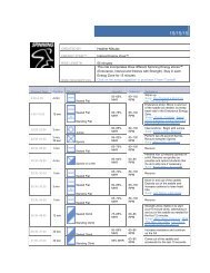
Spinning ® Ride Profile:<br />
This Strength Energy Zone ride takes a rider on three hills, each one a little longer, steeper and therefore more<br />
difficult. For the first hill, attempt to keep the heart rate at 80% max. Allow heart rate to rise to 85% with the<br />
second and third hills.<br />
Elapsed Time Duration Movement/Cadence Intensity Technique<br />
0:00 – 5:00 5 min Seated Flat<br />
80-110 RPM<br />
50-65% MHR Warm up for 5 minutes and allow<br />
heart rate to rise up to 65% MHR.<br />
5:00 – 9:00 4 min Seated Climb<br />
80 RPM<br />
80% MHR Settle in to the back of the saddle as<br />
you gradually add resistance and take<br />
your cadence to 80 RPM.<br />
9:00 – 12:00 3 min Seated Flat<br />
90-100 RPM<br />
75% MHR Unload resistance and increase<br />
cadence to 90-100 RPM. Find the<br />
right resistance to maintain a heart<br />
rate effort at 75%.<br />
12:00 – 20:00 8 min Seated Climb<br />
60-80 RPM<br />
80-85% MHR Add resistance to moderate/heavy<br />
and combine the two movements<br />
in any combination. Example: 3 min<br />
seated climb, 1 min jumps on a hill,<br />
repeat<br />
Jumps on a Hill<br />
60-80 RPM<br />
37
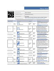
Elapsed Time Duration Movement/Cadence Intensity Technique<br />
20:00 – 23:00 5 min Seated Flat<br />
90-100 RPM<br />
75% MHR Unload resistance and increase cadence<br />
to 90-100 RPM. Find the right<br />
resistance to maintain a heart rate<br />
effort at 75%.<br />
23:00 – 35:00 12 min Seated Climb<br />
60-80 RPM<br />
Jumps on a Hill<br />
60-80 RPM<br />
80-85 MHR Add resistance to moderate/heavy<br />
and combine all three movements<br />
in any combination. Example: 2 min<br />
seated, 1 min jumps, 2 min standing,<br />
3 min seated, 2 min jumps, 2 min<br />
standing.<br />
Standing Climb<br />
60-80 RPM<br />
35:00 – 40:00 5 min Seated Flat<br />
80-110 RPM<br />
50-65% MHR Decrease resistance to light and allow<br />
HR to come down to 50-65%.<br />
38
This page intentionally left blank<br />
39
This page intentionally left blank<br />
40
For more information on <strong>Star</strong> <strong>Trac</strong> products and support<br />
visit http://support.startrac.com or call 800-503-1221.<br />
For more information on Spinning ® education, events,<br />
accessories and apparel log onto www.spinning.com.<br />
Spinning ® <strong>Computer</strong> <strong>Manual</strong><br />
620-7654 Rev H<br />
©2009 <strong>Star</strong> <strong>Trac</strong>. All Rights Reserved. <strong>Star</strong> <strong>Trac</strong> and the <strong>Star</strong> <strong>Trac</strong><br />
logo are registered trademarks of Unisen, Inc. Expect Different<br />
is a trademark of Unisen, Inc. SPIN ® , Spinning ® , Spinner ® , the<br />
Spinning ® logo and eSpinner ® are registered trademarks of Mad<br />
Dogg Athletics, Inc.