1975 Datsun 280z FSM - Spooled up Racing
1975 Datsun 280z FSM - Spooled up Racing
1975 Datsun 280z FSM - Spooled up Racing

Create successful ePaper yourself
Turn your PDF publications into a flip-book with our unique Google optimized e-Paper software.
,0 *•<br />
DATSUN<br />
- «;<br />
fjffl<br />
rfi<br />
i Sf,?J<br />
"•it* •%.'<br />
SERVICE<br />
MANUAL<br />
MODEL<br />
130 SERIES<br />
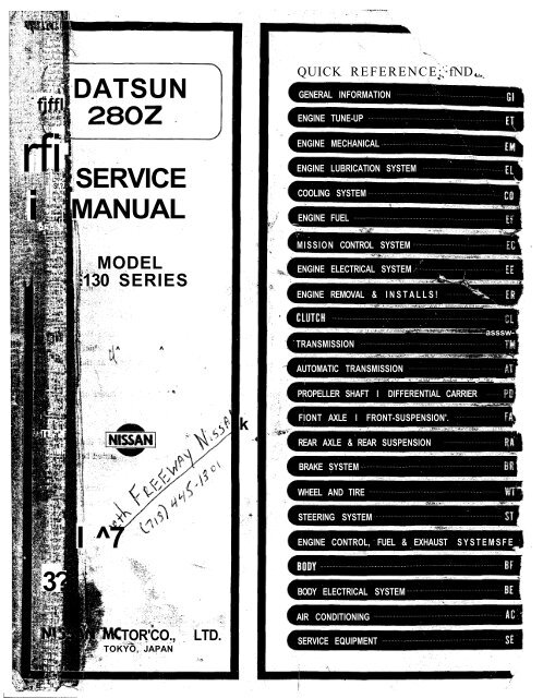
QUICK REFERENCE; fND.<br />
GENERAL INFORMATION<br />
ENGINE TUNE-UP<br />
ENGINE MECHANICAL<br />
ENGINE LUBRICATION SYSTEM<br />
COOLING SYSTEM<br />
ENGINE FUEL<br />
MISSION CONTROL SYSTEM<br />
ENGINE ELECTRICAL SYSTEM<br />
ENGINE REMOVAL & INSTALLS!<br />
' WW ' MWmWiWIlHtmn<br />
TJ""<br />
^<br />
^<br />
TRANSMISSION<br />
asssw-<br />
•"Sji<br />
AUTOMATIC TRANSMISSION<br />
^^f^^litK j.^.j < gUtiM****** jfcn&rm * v^J- , -^--^iKy. ^"<br />
PROPELLER SHAFT I DIFFERENTIAL CARRIER<br />
It *a* j<br />
ii.j<br />
k<br />
FIONT AXLE I FRONT-SUSPENSION'.<br />
REAR AXLE & REAR SUSPENSION<br />
BRAKE SYSTEM<br />
WHEEL AND TIRE<br />
I ^7<br />
STEERING SYSTEM<br />
ENGINE CONTROL, FUEL & EXHAUST<br />
SYSTEMSFE<br />
3?<br />
BODY ELECTRICAL SYSTEM<br />
TOR'CO.,<br />
TOKYO, JAPAN<br />
LTD.<br />
AIR CONDITIONING<br />
SERVICE EQUIPMENT
FOREWORD<br />
;r~~-<br />
This service manual has been prepared for the purpose of assisting service personnel of<br />
authorized NISSAN/DATSUN dealers in providing effective service and maintenance of the ,.<br />
<strong>1975</strong> <strong>Datsun</strong>280Z.<br />
Since proper maintenance and service are absolutely essential in satisfying the <strong>Datsun</strong><br />
owners, this manual should be kept in a handy place for ready reference and should be<br />
carefully studied.<br />
This manual includes procedures for maintenance adjustments, minor service operations,<br />
removal and installation, and for disassembly and assembly of components.<br />
Some of these service operations require the use of Special Tools especially designed for<br />
effective performance of service operations.<br />
The special tools are presented in the "SE" section.<br />
As you read through the maintenance procedures in this service manual, you will<br />
/* occasionally come across paragraphs headed NOTE or CAUTION. A NOTE is s<strong>up</strong>plemental<br />
information that is important to a particular procedure. CAUTION warns of steps that must<br />
be followed to prevent personal injury and/or damage to some part of your DATSUN.<br />
The Quick Reference Index on the first page enables the user to quickly locate the<br />
desired section. At the beginning of each individual section is a table of contents, which<br />
gives the page number on which each major subject begins. An index is placed at the<br />
beginning of each major subject within the section.<br />
All information, illustrations and specifications contained in this manual are based on<br />
the latest product information available at the time of publication approval.<br />
Rights for alteration at any time of specifications and methods are reserved.<br />
Liability for any personal injury or property damage occasioned by the use of this t»<br />
service manual in effecting maintenance or repair of your <strong>Datsun</strong> is in no way assumed b]<br />
Nissan Motor Co., Ltd.<br />
Accordingly, anyone using a service procedure or tool which is not specificalli<br />
recommended by Nissan must first completely satisfy himself that neither his safety no -<br />
the car's safety will be jeopardized by the service method selected.<br />
I<br />
NISSAN MOTOR CO., LTD<br />
TOKYO, JAPAN<br />
© 1974 NISSAN MOTOR CO., LTD. Printed in Japan
SECTION Gl<br />
c<br />
If<br />
DATSUN 280Z<br />
r^lODEL S30 SERIES<br />
GENERAL<br />
INFORMATION<br />
MODEL VARIATION Gl- 2<br />
IDENTIFICATION NUMBERS Gl- 3<br />
APPROXIMATE REFILL P, .<br />
Ul q<br />
CAPACITIES<br />
RECOMMENDED PETROL Pl A<br />
bl 4<br />
(FUEL)<br />
RECOMMENDED LUBRICANTS Gl- 4<br />
ISSAN<br />
LIFTING POINTS AND p| ,<br />
TOWING<br />
''<br />
D<br />
I SSAN MOTOR CO., LTD.<br />
TOKYO, JAPAN
General Information<br />
MODEL VARIATION<br />
Destination<br />
Class<br />
Model<br />
Engine<br />
Transmission model<br />
Tire size<br />
Differential gear carrier<br />
Model<br />
Gear ratio<br />
U.S.A.<br />
All areas except<br />
California<br />
California<br />
2-seater<br />
2 + 2-<br />
seater<br />
2-seater<br />
2 + 2-<br />
seater<br />
HLS30U<br />
HLS30AU<br />
GHLS30U<br />
GHLS30AU<br />
HLS30UV<br />
HLS30AUV<br />
GHLS30UV<br />
GHLS30AUV<br />
L28<br />
F4W71B<br />
3N71B<br />
F4W71 B<br />
3N71B<br />
F4W71B<br />
3N71B<br />
F4W71B<br />
3N71B<br />
175HR-14<br />
195/70HR<br />
14*<br />
R200<br />
3.545<br />
Canada<br />
2-seater<br />
2 + 2-<br />
seater<br />
HLS30UN<br />
HLS30AUN<br />
GHLS30UN<br />
GHLS30AUN<br />
F4W71B<br />
3N71B<br />
F4W71B<br />
3N71B<br />
Items with an asterisk "*": Optional equipment<br />
GHLS30AUNVC<br />
Air conditioner<br />
For California only<br />
For Canada only<br />
For U.S.A. and Canada<br />
Automatic transmission model<br />
Left hand drive<br />
L28 engine<br />
2 + 2 seater model<br />
GI-2
General Information<br />
IDENTIFICATION NUMBERS<br />
The unit and car numbers are<br />
stamped and registered at the factory.<br />
The engine and car identification<br />
numbers are used on legal documents.<br />
These numbers are used for factory<br />
communication such as Technical Report,<br />
Warranty Claim, Service Journal<br />
and other information.<br />
CAR SERIAL NUMBER<br />
The car serial number is stamped on<br />
the instrument panel and can be seen<br />
from outside. The car number consists<br />
of the car model and the serial number.<br />
(HLS30-XXXXX)<br />
CAR IDENTIFICATION PLATE «W<br />
The car identification plate is<br />
located on the left hoodledge panel at<br />
the back of strut housing.<br />
The plate contains the car type,<br />
engine capacity, maximum horsepower,<br />
wheelbase and engine and car<br />
serial numbers.<br />
GI198<br />
Fig. GI-2 Car serial number location<br />
GI199<br />
Fig. GI-3 Engine serial number<br />
location<br />
COLOR CODE<br />
NUMBER LABEL<br />
The body color number plate is<br />
attached on the top face of radiator<br />
core s<strong>up</strong>port.<br />
Car identification plate<br />
SP053<br />
Fig. GI-1 Car identification plate<br />
location<br />
ENGINE SERIAL NUMBER<br />
The engine serial number is stamped<br />
on the right side of the cylinder<br />
block.<br />
The number is broken down as<br />
shown in the following Figure GI-3.<br />
©<br />
-_<br />
f PAINT COLOR NUMBtft<br />
I COLO A NO. 2 f 4-<br />
{ PAINT AMtNO ALKYD £NAMfl<br />
° ZZ^T^<br />
GI200<br />
Fig. GI-4 Body color number<br />
location<br />
0<br />
to<br />
BODY AND UPHOLSTERY COLORS<br />
Body color number<br />
Body color<br />
Upholstery color<br />
1.<br />
110*<br />
Red<br />
Black, Beige<br />
2.<br />
214<br />
Brown Metallic<br />
Black, Coffee Brown<br />
3.<br />
301<br />
Bronze Metallic<br />
Black, Coffee Brown<br />
4.<br />
302<br />
Leaf Green Metallic<br />
Black, Beige, Coffee Brown<br />
5.<br />
303<br />
Green Metallic<br />
Black, Beige, Coffee Brown<br />
6.<br />
304<br />
Gold Metallic<br />
Black, Beige, Coffee Brown<br />
7.<br />
305<br />
Light Blue Metallic<br />
Black, Beige<br />
8.<br />
306<br />
Silver Metallic<br />
Black<br />
9.<br />
307<br />
Blue Metallic<br />
Black, Beige<br />
10.<br />
904*<br />
White<br />
Black<br />
Notes: a. Paint finish consists of two coats and one bake except for those marked with an asterisk,<br />
which indicates one coat and one bake.<br />
. b. The black-cloth <strong>up</strong>holstery color is optionally available for all body colors on Canada models.<br />
GI-3
General Information<br />
APPROXIMATE REFILL CAPACITIES<br />
Liters<br />
U.S. measure<br />
Imper.<br />
measure<br />
Fuel tank<br />
65<br />
17 X gal.<br />
14 Yi gal.<br />
Engine cooling system<br />
(with heater)<br />
^<br />
8.6<br />
(9.4)<br />
9Xqt.<br />
(10 qt.)<br />
7 %qt.<br />
(8 y K qt.)<br />
Engine crankcase *2<br />
4.7<br />
5 qt.<br />
4>£qt.<br />
Manual<br />
1.5<br />
3 Kpt.<br />
2 Kpt.<br />
Transmission case<br />
Automatic<br />
5.5<br />
5 Kqt.<br />
4Kqt.<br />
Differential case<br />
1.3<br />
2 y K pt.<br />
2 Kpt.<br />
*1 Includes 0.8 liter @4 U.S.gal., H Imper. gal.) required for heater.<br />
*2 Includes 0.7 liter (1 % U.S.pt., 1 l A Imper. pt.) required for oil filter replacement.<br />
RECOMMENDED PETROL (Fuel)<br />
Use an unleaded or low-lead<br />
gasoline with a minimum octane rating<br />
of 91 RON (Research Octane<br />
only unleaded gasoline to protect the<br />
catalytic converter from contamina-<br />
tion.<br />
Number).<br />
For cars which meet the California<br />
regulations (California Models), use<br />
RECOMMENDED LUBRICANTS<br />
RECOMMENDED SAE VISCOSITY NUMBER<br />
ENGINE OIL<br />
[20W-20, 10W-30,.10W-40, 20W-40, 20W-50 )<br />
C—<br />
• 5W-20, 5W-30<br />
| 10W 5W-30 10W-30, 10W-40 [<br />
I<br />
* SAE 5W-20 oils are not recommended<br />
for sustained high speed<br />
driving.<br />
GEAR OIL<br />
<<br />
-30<br />
i<br />
(<br />
75W<br />
I<br />
sow |<br />
I<br />
85W (<br />
I<br />
90<br />
,40<br />
-20 0 20 40 60 80 100<br />
Temperature Range Anticipated Before<br />
Next Oil Change °F<br />
I<br />
)<br />
GI-4
i<br />
General Information<br />
1<br />
LUBRICANT SPECIFICATION<br />
(For U.S.A. and Canada) from June 1, 1972.<br />
Item<br />
Gasoline engine oil<br />
Specifications<br />
SAE Classification<br />
SD or SE<br />
Remarks<br />
Furthermore refer to<br />
SAE recommended viscosity<br />
table. See Page 4.<br />
Gear oil<br />
Transmission<br />
and<br />
steering<br />
Differential<br />
API GL-4<br />
API GL-5<br />
Automatic T/M fluid<br />
Type DEXRON<br />
Multipurpose grease<br />
NLGI2<br />
Lithium soap base<br />
Brake and clutch fluid<br />
DOT 3<br />
Antifreeze<br />
Permanent anti-freeze<br />
(Ethylene glycol base)<br />
LIFTING POINTS AND TOWING<br />
JACK UP<br />
PANTOGRAPH JACK<br />
Place a jack under the position<br />
where sill flange is cut for identification.<br />
Do not jack <strong>up</strong> other positions.<br />
s<strong>up</strong>portable points are on both sides of<br />
front differential mounting crossmember.<br />
GI202<br />
Fig. G1-6 Front jacking point<br />
Notch<br />
Fig. GI-8<br />
GI204<br />
Front s<strong>up</strong>portable point<br />
GI201<br />
Fig. GI-5 Jacking point<br />
GARAGE JACK<br />
The front jacking point is center of<br />
front suspension member and rear is<br />
differential gear carrier.<br />
Do not place a jack on the center<br />
portion of front suspension transverse<br />
link.<br />
GI203<br />
Fig. GI-7 Rear jacking point<br />
SUPPORTABLE POINT<br />
Front s<strong>up</strong>portable points for stand<br />
are both front side members. Rear<br />
GI-5<br />
Fig. GI-9<br />
Rear s<strong>up</strong>portable point<br />
'.A
TOWING<br />
WARNING<br />
Only front hooks may be used for<br />
towing purposes. When front hooks<br />
are used for towing, remove front<br />
apron and front fender front to prevent<br />
possible interference with towing<br />
rope.<br />
Do not use rear hooks for towing,<br />
as these have been designed as tiedown<br />
hooks and are not strong enough<br />
to stand <strong>up</strong> to towing.<br />
Be sure to remove rear hooks before<br />
delivery of car. If rear hooks are<br />
not removed, they may cause interference<br />
with rear safety bumper and<br />
spoil its rear end collision safety performance.<br />
MANUAL TRANSMISSION<br />
MODEL<br />
When car is to be towed forward,<br />
connect a rope securely to hook attached<br />
to front side member.<br />
Before towing, make sure parking<br />
brake is released and transmission is in<br />
Neutral. See Figure GI-10.<br />
Caution: Always pull the rope in a<br />
straight direction with respect to<br />
hook.<br />
Do not apply force to hook in side<br />
directions.<br />
General Information<br />
Removing front<br />
apron and front<br />
fender front<br />
Fig. GI-10 Front towing point<br />
AUTOMATIC TRANSMISSION<br />
MODEL<br />
Car may be towed safely on its rear<br />
wheels on the ground with select lever<br />
in "N" (Neutral) position of at speeds<br />
of less than 20 MPH (32 km/h).<br />
However, propeller shaft must be disconnected<br />
or car must be towed on its<br />
front wheels on the ground under the<br />
following conditions:<br />
1. Tow speed of more than 20 MPH<br />
(32 km/h).<br />
2. Car must be towed for a long<br />
distance (over 6 miles or 10 km).<br />
3. Transmission is not operating properly.<br />
If car is towed on its front wheels<br />
on the ground, steering wheel should<br />
be secured to maintain a straight ahead<br />
position.<br />
TIE-DOWN HOOK<br />
There are four tie-down hooks.<br />
Two of them are located on front side<br />
members, and the other two on rear<br />
panel.<br />
Front tie-down hook attached to<br />
either side member is also used as a<br />
towing hook.<br />
Note: When fastening chains to rear<br />
transverse link, wrap them around<br />
link to avoid interfering with any<br />
adjacent parts.<br />
Fig. GI-11<br />
Front tie-down hook<br />
Fig. GI-12 Rear tie-down hook<br />
GI-6
.1ft.<br />
SECTION ET<br />
(• «I<br />
DATSUN 280Z<br />
MODEL S30 SERIES<br />
ENGINE<br />
TUNE-UP<br />
BASIC MECHANICAL SYSTEM ET- 3<br />
IGNITION AND FUEL SYSTEM ET- 5<br />
EMISSION CONTROL SYSTEM ET-10<br />
NISSAN<br />
TROUBLE DIAGNOSES AND FT qn<br />
CORRECTIONS<br />
LI ' JU<br />
NISSAN MOTOR CO., LTD.<br />
TOKYO, JAPAN
Engine Tune-<strong>up</strong><br />
Fig. ET-4 Cooler compressor belt<br />
tension<br />
RETIGHTENING<br />
CYLINDER HEAD<br />
BOLTS, MANIFOLD<br />
NUTS AND<br />
CARBURETOR<br />
SECURING NUTS<br />
Tightening torque:<br />
Cylinder head bolts<br />
1st turn:<br />
4.0 kg-m (29 ft-lb)<br />
2nd turn:<br />
6.0 kg-m (43 ft-lb)<br />
3rd turn:<br />
6.5 to 8.5 kg-m<br />
(47 to 61 ft-lb)<br />
Manifold nuts<br />
8 mm (0.315 in) dia. bolt<br />
1.4 to 1.8 kg-m<br />
(10.1 to 13.0 ft-lb)<br />
10 mm (0.394 in) dia. bolt<br />
4.5 to 5.5 kg-m<br />
(32.5 to 39.8 ft-lb)<br />
'O O O O O O O"<br />
12 8 4 2 6 10 14<br />
11 7 3 1 5 9 13<br />
o o o o o o o,<br />
EM269<br />
Fig. ET-5 Tightening sequence of<br />
cylinder head bolts<br />
CHANGING<br />
ENGINE OIL<br />
1. Check if oil is diluted with water<br />
or gasoline. Drain and refill oil if<br />
necessary.<br />
Notes:<br />
a. A milky oil indicates the presence<br />
of cooling water. Isolate the cause<br />
and take corrective measure.<br />
b. An oil with extremely low viscosity<br />
indicates dilution with gasoline.<br />
2. Check oil level. If below the<br />
specified level, raise it <strong>up</strong> to the H<br />
level.<br />
Engine oil capacity<br />
(including oil filter):<br />
Maximum (H level)<br />
4.7 (5 US qt, 4 Imp qt)<br />
Minimum (L level)<br />
3.7 (3 USqt, 3 Imp qt)<br />
REPLACING<br />
OIL FILTER<br />
Oil filter is of a cartridge type, and<br />
can be removed with Oil Filter Wrench<br />
ST19320000.<br />
1. Check for oil leaks past gasketed<br />
flange. If any leakage is found, retighten<br />
just enough to stop leakage. If<br />
re tightening is no longer effective,<br />
replace filter as an assembly.<br />
2. When installing oil filter, tighten<br />
by hand.<br />
Note: Do not overtighten oil filter,<br />
lest leakage should occur.<br />
CHANGING ENGINE<br />
COOLANT<br />
NISSAN LONG LIFE<br />
COOLANT (L.L.C.)<br />
The L.L.C. is an ethylene glycol<br />
concentration<br />
30%<br />
50%<br />
Sea level<br />
106°C<br />
(221°F)<br />
109°C<br />
(228°F)<br />
CHECKING COOLING<br />
SYSTEM HOSES AND<br />
CONNECTIONS<br />
Check hoses and fittings for loose<br />
connections or deterioration. Retighten<br />
or replace if necessary.<br />
ET-4<br />
base product containing chemical inhibitors<br />
to protect the cooling system<br />
from rusting and corrosion. The L.L.C.<br />
does not contain any glycerine or<br />
ethyl alcohol. It will not evaporate or<br />
boil away and can be used with either<br />
high or low temperature thermostats.<br />
It flows freely, transfers heat efficiently,<br />
and will not clog the passages in the<br />
cooling system. The L.L.C. must not<br />
be mixed with other product. This<br />
coolant can be used throughout the<br />
seasons of the year.<br />
Whenever coolant is changed, the<br />
cooling system must be flushed and<br />
refilled with a new coolant. Check the<br />
coolant level.<br />
°C (°F)<br />
0 (321 -v^^<br />
-10 (14) - ^ \<br />
-20 (-4) - I \<br />
-30 (-22) - ' \<br />
-40 (-40) - ! !\<br />
I<br />
-50 (-58) I 1 1 1 1 1<br />
10 20 30 40 50<br />
Boiling point<br />
EG001<br />
Fig. ET-6 Protection concentration<br />
0.9 kg/cm 2 (13 psi)<br />
cooling system pressure<br />
124°C(255°F)<br />
127°C(261°F)<br />
INSPECTION OF<br />
RADIATOR CAP<br />
Freeze protection<br />
-15°C(5°F)<br />
-35°C(-31°F)<br />
Apply reference pressure [0.9<br />
kg/cm 2 (13 psi)] to radiator cap by<br />
means of a cap tester to see if it is<br />
satisfactory. Replace cap assembly if<br />
necessary.<br />
i
Engine Tune-<strong>up</strong><br />
v<br />
ET012<br />
Fig. ET-7 Testing radiator cap<br />
COOLING SYSTEM<br />
PRESSURE TEST<br />
"With radiator cap removed, apply<br />
reference pressure [1.6 kg/cm 2 (23<br />
psi)] to the cooling system by means<br />
of a tester to detect any leakage.<br />
Water capacity (with heater):<br />
9.4 (10 US gal, 8 Imp gal)<br />
ET237<br />
Fig. ET-8 Cooling system<br />
pressure test<br />
CHECKING VACUUM<br />
FITTINGS, HOSES,<br />
AND CONNECTIONS<br />
Check fittings and hoses for loose<br />
connections or damage. Re tighten<br />
loose parts or replace parts that are<br />
not suitable for further use.<br />
CHECKING ENGINE<br />
COMPRESSION<br />
To check cylinder compression, it is<br />
essential to remove all spark plugs. The<br />
purpose of this test is to determine<br />
whether there is excessive leakage past<br />
piston rings, head gasket, etc. To test,<br />
engine should be heated to the operating<br />
temperature and throttle and<br />
choke valves opened.<br />
Cylinder compression in cylinders<br />
should not be less than 80% of the<br />
highest reading. Different compression<br />
in two or more cylinder usually indicates<br />
an improperly seated valve or<br />
broken piston ring.<br />
Low compression in cylinders can<br />
result from worn piston rings. This<br />
trouble may usually be accompanied<br />
by excessive fuel consumption.<br />
17 -^e<br />
ET010<br />
Fig. ET-9 Testing compression<br />
pressure<br />
TESTING RESULT<br />
If cylinder compression in one or<br />
more cylinders is low, pour a small<br />
quantity of engine oil into cylinders<br />
through the spark plug holes and retest<br />
compression.<br />
1. If adding oil helps the compression<br />
pressure, the chances are that<br />
piston rings are worn or damaged.<br />
2. If pressure stays low, the likelihood<br />
is that valve is sticking or seating<br />
improperly.<br />
3. If cylinder compression in any<br />
two adjacent cylinders is low, and if<br />
adding oil does not help the compression,<br />
there is leakage past the gasketed<br />
surface.<br />
Oil and water in combustion chambers<br />
can result from this trouble.<br />
Compression pressure kg/cm<br />
(psi)/at rpm:<br />
11.5 to 12.5 (164 to 178)<br />
IGNITION AND FUEL SYSTEM<br />
CONTENTS<br />
CHECKING BATTERY<br />
CHECKING AND ADJUSTING IGNITION<br />
TIMING<br />
CHECKING AND REPLACING SPARK<br />
PLUGS<br />
CHECKING OPERATING PARTS OF<br />
DISTRIBUTOR AND IGNITION WIRING<br />
AIR GAP<br />
DISTRIBUTOR . . . •.<br />
HIGH TENSION CABLE . ;<br />
ET-6<br />
ET-6<br />
ET-6<br />
ET-7<br />
ET-7<br />
ET-7<br />
ET-7<br />
CHECKING DISTRIBUTOR CAP ROTOR<br />
ADJUSTING ENGINE IDLE RPM<br />
DASH POT ADJUSTMENT<br />
CHECKING FUEL LINES (HOSES,<br />
PIPING CONNECTIONS, ETC.)<br />
REPLACING RUBBER FUEL HOSES<br />
IN ENGINE COMPARTMENT<br />
REPLACING FUEL FILTER<br />
CHECKING AIR REGULATOR HOSES<br />
REPLACING AIR CLEANER ELEMENT<br />
ET-7<br />
ET-7<br />
ET-8<br />
ET-8<br />
ET-8<br />
ET-9<br />
ET-9<br />
ET-9<br />
ET-5<br />
A
Engine Tune-<strong>up</strong><br />
CHECKING BATTERY<br />
Check electrolyte level in each battery<br />
cell.<br />
1. Unscrew each filler cap and inspect<br />
fluid level. If the level is low, add<br />
distilled water to bring the level <strong>up</strong><br />
approximately 10 to 20 mm (0.39 to<br />
0.79 in) above plates. Do not overfill.<br />
2. Measure the specific gravity of<br />
battery electrolyte.<br />
Permissible value<br />
Fig. ET-10<br />
ET238<br />
Checking specific gravity<br />
of battery electrolyte<br />
Full charge value<br />
[at20°C(68°F)]<br />
If necessary, adjust it as follows.<br />
(1) Loosen set screw until distributor<br />
can be moved by hand.<br />
(2) Adjust ignition timing to specifications.<br />
(3) Lock distributor set screw, and<br />
make sure that timing is correct.<br />
Frigid climates<br />
Over 1.22<br />
1.28<br />
Tropical climates<br />
Other climates<br />
Over 1.18<br />
Over 1.20<br />
1.23<br />
1.26<br />
Fig. ET-11<br />
ET239<br />
Adjusting ignition timing<br />
Clean top of battery and terminals<br />
with a solution of baking soda and<br />
water. Rinse off and dry with compressed<br />
air. Top of battery must be<br />
clean to prevent current leakage between<br />
terminals and from positive<br />
terminal to hold-down clamp.<br />
In addition to current leakage,<br />
prolonged accumulation of acid and<br />
dirt on top of battery may cause<br />
blistering of the material covering connector<br />
straps and corrosion of straps.<br />
After tightening terminals, coat them<br />
with petrolatum (vaseline) to protect<br />
them from corrosion.<br />
CHECKING AND<br />
ADJUSTING<br />
IGNITION TIMING<br />
1. Check spark plugs and distributor<br />
breaker points for condition.<br />
2. Thoroughly remove dirt and dust<br />
Non-California model<br />
from crank pulley at timing mark<br />
location and front cover at timing<br />
indicator.<br />
3. Warm <strong>up</strong> engine sufficiently.<br />
4. Connect engine tachometer and<br />
timing light in their proper positions.<br />
5. Adjust idling speed to 800 rpm<br />
by turning idle speed adjusting screw<br />
on manual transmission models.<br />
On automatic transmission models,<br />
adjust it to about 700 rpm with<br />
selector lever in "D" range.<br />
Caution: When selector lever is shifted<br />
to "D" range, apply parking brake<br />
and block both front and rear<br />
wheels with chocks.<br />
6. Check ignition timing with a<br />
timing light to ensure that it is adjusted<br />
to specifications indicated in<br />
the chart below.<br />
Ignition timing<br />
California model<br />
ET240<br />
Fig. ET-12 Ignition timing indicator<br />
CHECKING AND<br />
REPLACING SPARK<br />
PLUGS<br />
Remove and clean plugs in a sand<br />
blast cleaner. Inspect each spark plug.<br />
Make sure that they are of the specified<br />
heat range. Inspect insulator for<br />
cracks or chips. Check both center and<br />
ground electrodes. If they are excessively<br />
worn, replace with new spark<br />
plugs. File center electrode flat. Set<br />
the gap to 0.8 to 0.9 mm (0.031 to<br />
0.035 in) using the proper adjusting<br />
tool. Tighten plugs to 1.5 to 2.0kg-m<br />
(11 to 14 ft-lb) torque.<br />
Manual transmission<br />
7° B.T.D.C/800 rpm<br />
(Retarded)<br />
13° B.T.D.C/800 rpm<br />
(Advanced) *<br />
10° B.T.D.C/800 rpm<br />
Automatic transmission<br />
(in "D" range)<br />
7° B.T.D.C/700 rpm<br />
(Retarded)<br />
13° B.T.D.C/700 rpm<br />
(Advanced)<br />
10° B.T.D.C/700 rpm<br />
After engine warming <strong>up</strong>, ignition timing is retarded. Advanced ignition timing<br />
adjustment is necessary only when adjusting phase difference.<br />
ET-6<br />
EE080<br />
Fig. ET-13 Checking spark plug<br />
gap
CHECKING OPERATING<br />
PARTS OF<br />
DISTRIBUTOR AND<br />
IGNITION WIRING<br />
AIR GAP<br />
Standard air gap is 0.2 to 0.4 mm<br />
(0.008 to 0.016 in) (both single gap<br />
and dual gap distributors).<br />
If the gap is off the standard,<br />
adjustment should be made by loosening<br />
pick-<strong>up</strong> coil screws. Gap gauge is<br />
required for adjustment.<br />
Air gap:<br />
0.2 to 0.4 mm<br />
(0.008 to 0.016 in)<br />
Engine Tune-<strong>up</strong><br />
DISTRIBUTOR<br />
Check the centrifugal mechanical<br />
parts for loose connection, sticking of<br />
spring, or excessive or local wear.<br />
If found to be in good condition,<br />
then check advance characteristics<br />
using a distributor tester. For test<br />
procedure and reference data, refer to<br />
Distributor in Section EE.<br />
If vacuum advance unit fails to<br />
operate properly, check the following<br />
items and correct as necessary:<br />
1. Check vacuum inlet for leakage at<br />
connection. If necessary, retighten or<br />
replace.<br />
2. Check vacuum diaphragm for air<br />
leak.<br />
If leak is found, replace diaphragm.<br />
3. Inspect breaker plate for smooth<br />
operation.<br />
If plate does not move smoothly,<br />
this may be caused by sticky steel balls<br />
or pivot. Apply grease to steel balls or,<br />
if necessary, replace breaker plate as<br />
an assembly. Refer to Section EE,<br />
Distributor, as regards vacuum advance<br />
characteristics.<br />
CHECKING<br />
DISTRIBUTOR CAP<br />
ROTOR<br />
Note: This operation is to be performed<br />
while checking distributor<br />
points. Inspect distributor cap for<br />
cracks and flash over.<br />
External surfaces of all parts of<br />
secondary system must be cleaned to<br />
reduce possibility of voltage loss. All<br />
wires should be removed from distributor<br />
cap and coil so that terminals<br />
can be inspected and cleaned. Burned<br />
or corroded terminals indicate that<br />
wires are not fully seated, which<br />
causes arcing between end of wire and<br />
terminal. When replacing wires at terminal,<br />
be sure they are fully seated<br />
before pushing rubber nipple down<br />
over tower. Check distributor rotor for<br />
damage, and distributor cap for cracks.<br />
Apply grease through the top of<br />
distributor shaft.<br />
ET241<br />
Fig. ET-14 Measuring air gap<br />
Remove rubber cap from tip end of<br />
rotor shaft. Check grease and, if necessary,<br />
add. To remove pick-<strong>up</strong> coil,<br />
remove two pick-<strong>up</strong> coil assembly securing<br />
screws and core screws clamping<br />
primary lead wire. Install new<br />
pick-<strong>up</strong> coil assembly in reverse sequence<br />
of removal.<br />
HIGH TENSION CABLE<br />
Use an ohmmeter to check resistance<br />
on high tension cables. Disconnect<br />
cables from spark plugs and remove<br />
distributor together with high<br />
tension cables. Do not remove cables<br />
from cap. Connect the ohmmeter between<br />
cable terminal on the spark plug<br />
side and the corresponding electrode<br />
inside cap.<br />
If the resistance is more than<br />
30,000 ohms, remove cable from cap<br />
and check the cable resistance only. If<br />
resistance is still more than 30,000<br />
ohms, replace cable assembly.<br />
ADJUSTING ENGINE<br />
IDLE RPM<br />
As the electronic fuel injection<br />
system is used in the engine, air-fuel<br />
mixture ratio adjustment cannot be<br />
made. Consequently, measurement of<br />
CO percentage is not necessary when<br />
making idle adjustment.<br />
Cautions:<br />
a. On automatic transmission models,<br />
checks should be performed with<br />
the lever shifted to the "D" range.<br />
Be sure to engage parking brake and<br />
to lock both front and rear wheels<br />
with wheel chocks.<br />
b. Depress brake pedal while accelerating<br />
the engine to prevent forward<br />
surge of car.<br />
c. After idle adjustment has been<br />
made, shift the lever to the "N" or<br />
"P" range and remove wheel<br />
chocks.<br />
Fig. ET-15<br />
ET242<br />
Removing pick-<strong>up</strong> coil<br />
Fig. ET-16<br />
EF125<br />
Checking high tension<br />
cable<br />
1. Warm-<strong>up</strong> engine sufficiently.<br />
2. Adjust idle speed adjusting screw<br />
until specified engine speed is reached<br />
as follows:<br />
ET-7
Engine speed:<br />
Manual transmission:<br />
800 rpm<br />
Automatic transmission<br />
(in "D" range):<br />
700 rpm<br />
3. Check ignition timing. If necessary,<br />
adjust it to specifications.<br />
Engine Tune-<strong>up</strong><br />
Fig. ET-17 Adjusting idling speed<br />
CHECKING FUEL<br />
LINES<br />
(HOSES, PIPING<br />
CONNECTIONS, ETC.)<br />
Check fuel hoses for leakage, loose<br />
connections, cracks or deterioration.<br />
Retighten loose connections and<br />
replace any damaged or deformed<br />
parts. Replace any rubber fuel hose<br />
whose inner surface is deformed,<br />
scratched or chafed.<br />
Non-California model<br />
Ignition timing<br />
California model<br />
i<br />
Manual transmission<br />
7° B.T.D.C/800 rpm<br />
(Retarded)<br />
13° B.T.D.C/800 rpm<br />
(Advanced) *<br />
10° B.T.D.C/800 rpm<br />
Automatic transmission<br />
(in "D" range)<br />
7° B.T.D.C/700 rpm<br />
(Retarded)<br />
13° B.T.D.C/700 rpm<br />
(Advanced) *<br />
10° B.T.D.C/700 rpm<br />
After engine warming <strong>up</strong>, ignition timing is retarded. Advanced ignition timing<br />
adjustment is necessary only when adjusting phase difference.<br />
Dashpot adjustment<br />
Make sure that the clearance between<br />
idle setscrew (preset at the<br />
factory) and throttle lever is 1.9 mm<br />
(0.0748 in). Use shim(s) or suitable<br />
gauge to measure the clearance. A<br />
clearance of 1.9 mm (0.0748 in) between<br />
these two points corresponds to<br />
2,000 engine rpm under no load.<br />
Check that the dashpot rod end<br />
closely touches throttle lever when<br />
dashpot rod is fully extended (or when<br />
no back pressure is present at diaphragm).<br />
If necessary, loosen nut<br />
(shown by an arrow) and turn dashpot<br />
assembly until correct adjustment is<br />
made.<br />
REPLACING<br />
RUBBER FUEL<br />
HOSES IN ENGINE<br />
COMPARTMENT<br />
The rubber fuel hoses in the engine<br />
compartment which are shown by<br />
arrows in Figure ET-19, should be<br />
replaced every 40,000 km (25,000<br />
miles).<br />
]<br />
1.9 mm (0.0748 in) —<br />
ET425<br />
Fig. ET-18 Dashpot adjustment<br />
ET-8
Engine Tune-<strong>up</strong><br />
Rubber fuel hoses in the engine<br />
compartment which require periodic<br />
replacement are shown in the illustration<br />
below.<br />
Fig. ET-19 Fuel rubber hoses in engine compartment<br />
Rubber Hose Name<br />
Rubber Hose - Fuel Tube to Fuel Filter<br />
Rubber Hose - Fuel Filter to Fuel Pipe A<br />
Rubber Hose - 4 Way Connector to Fuel Pipe B<br />
Rubber Hose - Fuel Pipe B to Pressure Regulator<br />
Rubber Hose - 4 Way Connector to Fuel Pipe C<br />
Rubber Hose - Fuel Pipe C to Pressure Regulator<br />
Rubber Hose - Pressure Regulator to Fuel Return Pipe<br />
Rubber Hose - Fuel Return Pipe to Fuel Tank<br />
Rubber Hose - 4 Way Connector to Cold Start Valve<br />
Rubber Hose - Fuel Pipe B to Injector<br />
Rubber Hose - Fuel Pipe C to Injector<br />
Length mm (in)<br />
180 ( 7.09 )<br />
240 ( 9.45 )<br />
95 ( 3.740)<br />
45 ( 1.772)<br />
95 ( 3.740)<br />
45 ( 1.772)<br />
95 ( 3.740)<br />
500(19.69 )<br />
275(10.83 )<br />
38 ( 1.496)<br />
38 ( 1.496)<br />
Number<br />
3<br />
3<br />
ET-9
Replacing injector hose<br />
When replacing injector hoses (as<br />
recommended in the Periodical<br />
Maintenance), proceed as follows:<br />
1. Remove injector as outlined in<br />
Steps 1 through 14 under heading<br />
"Removal and Installation".<br />
2. Cut metal band caulking injector<br />
hose to injector with a grinding wheel<br />
or file.<br />
Fig. ET-22 Installing injector hose<br />
Hose clamp tightening torque:<br />
0.1 to0.15kg-cm<br />
(1.4 to 2.1 in-oz)<br />
CHECKING AIR<br />
REGULATOR HOSES<br />
Check air regulator hoses for<br />
leakage, cracks and deterioration.<br />
Retighten loose connections and<br />
replace any parts if they are damaged<br />
or deformed.<br />
Air regulator hoses<br />
Fig. ET-20 Cutting metal band<br />
caulking injector hose to<br />
injector<br />
Cautions:<br />
a. Be careful not to scratch any adjacent<br />
parts.<br />
b. Place a clean rag over injector to<br />
prevent metal chips from contacting<br />
injector nozzle.<br />
c. Hold injector when filing it. Never<br />
place it in a vice.<br />
d. If a grinding wheel is used in place<br />
of file, be careful not to allow<br />
injector becoming too hot as this<br />
can damage internal coil.<br />
Cautions:<br />
a. Do not reuse injector gasket and<br />
O-rings after removal.<br />
b. Do not reuse fuel hose clamps after<br />
loosening.<br />
c. Before assembling parts, remove<br />
dust and dirt with compressed air.<br />
d. Be sure to install 13.5 mm (0.531<br />
in) hose clamps on the injector and<br />
fuel pipe side. Each clamp has a size<br />
mark on it.<br />
e. Replace hoses which have been<br />
scratched or deformed.<br />
f. After inserting fuel hose into fuel<br />
pipe securely, clamp at a position<br />
10 mm (0.394 in) from the hose<br />
end.<br />
REPLACING FUEL<br />
FILTER<br />
The fuel filter is designed especially<br />
for use with the electronic fuel injection<br />
system. It should be replaced as<br />
an assembly every 40,000 km (25,000<br />
miles).<br />
For removal and installation procedures,<br />
refer to section "Engine<br />
Fuel".<br />
Fig. ET-24 Air regulator hoses<br />
REPLACING AIR<br />
CLEANER ELEMENT<br />
The viscous paper type air cleaner<br />
element does not require any cleaning<br />
operation between renewals.<br />
Brushing or blasting operation can<br />
cause a clogged element. This in turn<br />
reduces air intake efficiency, resulting<br />
in poor engine performance.<br />
For replacement intervals of air<br />
cleaner element, refer to "Maintenance<br />
Schedule".<br />
Fig. ET-21 Cutting metal band<br />
3. Remove metal band with a pair of<br />
pliers.<br />
4. Disconnect injector hose.<br />
5. Install new injector hose, and<br />
secure with hose clamp designed for<br />
the purpose. Install clamp as close to<br />
injector as possible so that hose clamp<br />
screw is positioned with respect to<br />
electric connector as shown in Figure<br />
EF-140.<br />
Fig. ET-23 Fuel filter<br />
ET-10<br />
Fig. ET-25 Air cleaner element
Engine Tune-<strong>up</strong><br />
EMISSION CONTROL SYSTEM<br />
CONTENTS<br />
CHECKING CRANKCASE EMISSION<br />
CONTROL SYSTEM<br />
ET-10<br />
P.C.V. VALVE • ET-10<br />
VENTILATION HOSE<br />
ET-10<br />
ADJUSTING OPERATING PRESSURE OF BOOST<br />
CONTROLLED DECELERATION DEVICE<br />
(B.C.D.D.)<br />
ET-11<br />
CHECKING B.C.D.D. CIRCUIT WITH<br />
FUNCTION TEST CONNECTOR<br />
CHECKING SPARK TIMING CONTROL<br />
SYSTEM (Except California)<br />
DESCRIPTION<br />
INSPECTION AND ADJUSTMENT<br />
WATER TEMPERATURE SWITCH<br />
RELAY<br />
CHECKING TRANSMISSION CONTROLLED<br />
VACUUM ADVANCE SYSTEM<br />
(Manual transmission models only except<br />
California)<br />
ET-11<br />
ET-14<br />
ET-14<br />
ET-15<br />
ET-15<br />
ET-15<br />
ET-16<br />
CHECKING EXHAUST GAS RECIRCULATION<br />
(E.G.R.) CONTROL SYSTEM<br />
(For California)<br />
CHECKING E.G.R. CONTROL SYSTEM<br />
ON ENGINE<br />
CHECKING EACH COMPONENT<br />
INDEPENDENTLY<br />
CHECKING EVAPORATIVE EMISSION<br />
CONTROL SYSTEM<br />
FUEL TANK, VAPOR LIQUID<br />
SEPARATOR AND VAPOR VENT LINE....<br />
CARBON CANISTER PURGE CONTROL<br />
VALVE<br />
CARBON CANISTER Fl LTER<br />
FUEL TANK VACUUM RELIEF VALVE ...<br />
CHECKING CATALYTIC CONVERTER<br />
(For California)<br />
CHECKING FLOOR TEMPERATURE<br />
WARNING SYSTEM<br />
ET-16<br />
ET-16<br />
ET-17<br />
ET^17<br />
ET-17<br />
ET-18<br />
ET-18<br />
ET-18<br />
ET-18<br />
ET-27<br />
CHECKING CRANKCASE EMISSION CONTROL SYSTEM<br />
c=> Fresh air<br />
•+ Blow-by gas<br />
ET-11<br />
Fig. ET-26<br />
O-ring<br />
Oil level gauge<br />
Baffle plate<br />
Oil cap<br />
Flame arrester<br />
Throttle chamber<br />
P.C.V. valve<br />
Steel net<br />
Baffle plate<br />
EC366<br />
Crankcase emission control system
P.C.V. VALVE<br />
Check P.C.V. valve in accordance<br />
with the following method.<br />
With engine running at idle, remove<br />
the ventilator hose from P.C.V. valve.<br />
If the valve is working, a hissing noise<br />
will be heard as air passes through the<br />
valve and a strong vacuum should be<br />
felt immediately when a finger is<br />
placed over valve inlet.<br />
Replace P.C.V. valve in accordance<br />
with the maintenance schedule.<br />
Engine Tune-<strong>up</strong><br />
If continuity does not exist, check<br />
for disconnected connector and/or<br />
faulty amplifier, speed detecting<br />
switch or B.C.D.D. solenoid valve.<br />
2. Check for presence of voltage<br />
across A and B [at a speed ot more<br />
than 16 km/h* (10 MPH)]. Refer to<br />
Figure ET-25.<br />
* Conduct this test by one of the<br />
following two methods.<br />
1) Raising <strong>up</strong> rear axle housing with<br />
stand.<br />
2) Chassis dynamometer test<br />
• If voltmeter reading is 0 volt at a<br />
speed of more than 16 km/h (10<br />
MPH), circuit is functioning properly.<br />
• If voltmeter reading is not 0 volt,<br />
check for disconnected connector,<br />
burned fuse, faulty amplifier,<br />
B.C.D.D. solenoid valve or speed<br />
detecting switch.<br />
3. If, by above checks, faulty part or<br />
unit is located, it should be removed<br />
and tested again. If necessary, replace.<br />
VENTILATION HOSE<br />
1. Check hoses and hose connections<br />
for leaks.<br />
2. Disconnect all hoses and clean<br />
with compressed air.<br />
If any hose cannot be freed of<br />
obstructions, replace.<br />
Ensure that flame arrester is surely<br />
inserted in hose between throttle<br />
chamber and rocker cover.<br />
ADJUSTMENT<br />
OPERATING<br />
PRESSURE OF<br />
BOOST CONTROLLED<br />
DECELERATION<br />
DEVICE (B.C.D.D.)<br />
CHECKING B.C.D.D.<br />
CIRCUIT WITH FUNCTION<br />
TEST CONNECTOR<br />
Fig. ET-27<br />
Automatic transmission models<br />
1. Turn ignition key to "ON" position.<br />
2. With inhibitor switch "ON" ("N"<br />
or "P" range), check for presence of<br />
voltage across A and B. Refer to<br />
Figure ET-25.<br />
• If voltmeter reading is 12 volts<br />
(d-c), B.C.D.D. circuit is functioning<br />
properly.<br />
• If voltmeter reading is zero, check<br />
for disconnected connector, faulty<br />
solenoid valve or inhibitor switch.<br />
3. With inhibitor switch "OFF"<br />
EC373<br />
Ignition key<br />
Fuse<br />
Amplifier<br />
Speed detecting switch<br />
Above lOmph: OFF<br />
Below lOmph: ON<br />
Function test connector<br />
Vacuum control solenoid<br />
valve<br />
Checking B.C.D.D. circuit with function test connector<br />
(for manual transmission)<br />
("1", "2", "D" or "R" range), check<br />
for resistance between A and B. Refer<br />
to Figure ET-25.<br />
• If ohmmeter reading is 15 to 28<br />
ohms, circuit is functioning properly.<br />
• If ohmmeter reading is not above,<br />
check for poor connection of connector,<br />
faulty B.C.D.D. solenoid<br />
valve or inhibitor switch.<br />
4. If, by above checks, faulty part or<br />
unit is located, it should be removed<br />
and tested again. If necessary, replace.<br />
Caution: Do not attach test leads of a<br />
circuit tester to those other than<br />
designated.<br />
Manual transmission models<br />
1. Check for continuity between A<br />
and B when car is brought to a<br />
complete stop. Refer to Figure ET-25.<br />
B.C.D.D. circuit is functioning properly<br />
if continuity exists and voltmeter<br />
reading is 0 volts (d-c) in step 2<br />
below.<br />
Fig. ET-28<br />
ET-12<br />
Ignition key<br />
Inhibitor switch<br />
N.P. range: ON<br />
1, 2, D, R, range: OFF<br />
3 Vacuum control<br />
solenoid valve<br />
4 Function test connector<br />
EC374<br />
Checking B.C.D.D. circuit with function test connector
Engine Tune-<strong>up</strong><br />
Checking vacuum control<br />
solenoid valve<br />
1. Turn on engine key. (Do not start<br />
engine.)<br />
2. Ensure that solenoid valve clicks<br />
when intermittently electrified as<br />
shown in Figure ET-28.<br />
3. If a click is heard, solenoid valve<br />
is normal.<br />
4. If a click is not heard at all, check<br />
for continuity with a circuit tester. If<br />
discontinuity is detected, replace solenoid<br />
valve.<br />
Checking<br />
amplifier (Manual<br />
transmission models)<br />
The amplifier is installed at the rear<br />
Checking inhibitor switch<br />
(Automatic transmission<br />
models)<br />
Refer to the TM section.<br />
<br />
©<br />
Adjustment of set pressure<br />
of B.C.D.D.<br />
Generally, it is unnecessary to adjust<br />
the B.C.D.D., however, if it should<br />
become necessary to adjust it, the<br />
procedure is as follows:<br />
Prepare the following tools<br />
1. Tachometer to measure the engine<br />
speed while idling, and a screwdriver.<br />
2. A vacuum gauge and connecting<br />
pipe.<br />
Note: A quick-response type boost<br />
M<br />
of the speedometer. To check, proceed<br />
as follows:<br />
1. Set circuit tester in d-c ampere<br />
range (1A min, full scale), connect test<br />
probes of tester as shown in Figure<br />
ET-29.<br />
Do not confuse positive line with<br />
negative line.<br />
2. Turn ignition key to "ON" position.<br />
3. Ensure that tester pointer deflects<br />
when ignition key is turned on.<br />
4. If tester pointer does not deflect<br />
when solenoid valve and speed detecting<br />
switch circuits are functioning<br />
properly, amplifier is faulty.<br />
3!<br />
Fig. ET-29<br />
1 Ignition key<br />
2 Amplifire<br />
3 Speed detecting switch<br />
Above 10 mph : OFF<br />
Below 10 mph : ON<br />
4 B.C.D.D. solenoid valve<br />
EC376<br />
Checking amplifier<br />
gauge such as Bourdon's type is<br />
recommended; a mercury-type<br />
manometer should not be used.<br />
To properly set the B.C.D.D. set<br />
pressure, proceed as follows:<br />
1. Remove the harness of solenoid<br />
valve.<br />
Solenoid valve harness<br />
EC377<br />
Fig. ET-30 Removing harness of<br />
solenoid valve<br />
ET-13<br />
2. Connect rubber hose between<br />
vacuum gauge and intake manifold as<br />
shown in Figure ET-33.<br />
EC378<br />
Fig. ET-31 Connecting vacuum gauge<br />
3. Warm <strong>up</strong> the engine until it is<br />
heated to operating temperature.<br />
Then adjust the engine at normal<br />
idling setting. (Refer to the item<br />
"Idling Adjustment" in page ET-7.)<br />
Idling engine speed<br />
Manual transmission<br />
800 rpm<br />
Automatic transmission<br />
(in "D" position)<br />
700 rpm<br />
4. Run the engine under no load.<br />
Increase engine speed to 3,000 to<br />
3,500 rpm, then quickly close throttle<br />
valve.<br />
5. At that time, the manifold vacuum<br />
pressure increases abr<strong>up</strong>tly to<br />
-600 mmHg (-23.62 inHg) or above<br />
and then gradually decreases to the<br />
level set at idling.<br />
6. Check that the B.C.D.D. set pressure<br />
is within the specified pressure.<br />
Specified pressure (0 m, sea level<br />
and 760 mmHg (30 inHg) atmospheric<br />
pressure)<br />
Manual transmission:<br />
-460 to -480 mmHg<br />
(-18.1 to-18.9 inHg)<br />
Automatic transmission:<br />
-460 to -480 mmHg<br />
(-18.1 to-18.9 inHg)<br />
Notes:<br />
a. When atmospheric pressure is<br />
known, operating pressure will be<br />
found by tracing the arrow line<br />
"A". See Figure ET-34. When altitude<br />
is known, operating pressure<br />
will be found by tracing the arrow<br />
line "B". See Figure ET-34.
Engine Tune-<strong>up</strong><br />
b. When checking the set pressure of<br />
B.C.D.D., find the specified set<br />
pressure in Figure ET-32 from the<br />
atmospheric pressure and altitude<br />
of the given location.<br />
For example, if the car is located at<br />
an altitude of 1,400 m (4,600 ft),<br />
the specified set pressure for<br />
B.C.D.D. is 396 mmHg (15.6 inHg).<br />
7. If it is higher than the set level,<br />
turn the adjusting screw counterclockwise<br />
until correct adjustment is made.<br />
EC 409<br />
Fig. ET-32 Adjusting set pressure<br />
8. Race the engine and check for<br />
adjustment.<br />
9. If it is lower than the set level.<br />
turn the adjusting screw clockwise<br />
until correct adjustment is made.<br />
10. Race the engine and check for<br />
adjustment.<br />
If engine speed cannot be decreased<br />
to idling when checking B.C.D.D. set<br />
pressure, proceed as follows:<br />
When the engine speed does not fall<br />
to idling speed, it is necessary to<br />
reduce the negative idling pressure of<br />
the manifold to lower than the set<br />
pressure of the B.C.D.D. (The engine<br />
speed will not drop to idling speed<br />
when the negative idling pressure is<br />
higher than the set pressure of the<br />
B.C.D.D.).<br />
In this case, the engine must be<br />
labored by (1) road test or (2) chassis<br />
dynamometer or (3) by raising <strong>up</strong> rear<br />
suspension member on a stand, accelerating<br />
the car to 64 to 80 km/h (40<br />
to 50 MPH) in top gear (manual<br />
transmission) or in "D" range (automatic<br />
transmission), and then releasing<br />
the accelerator pedal and letting the<br />
car decelerate. After doing this, check<br />
whether the B.C.D.D. set pressure is at<br />
the predetermined value or not.<br />
-Vacuum gauge Vacuum gauge Vacuum gauge<br />
ET133<br />
(1) Road test (2) Chassis dynamometer ^^ ^^ (3) Raise <strong>up</strong> rear axle housing by stand<br />
Fig. ET-33 Testing operating pressure of the B. C.D.D.<br />
a<br />
d<br />
a.<br />
O<br />
(mmHg) (inHg) \<br />
<<br />
24 V'cu M<br />
r<br />
600<br />
550<br />
500<br />
450<br />
400<br />
350<br />
-<br />
23<br />
22<br />
21<br />
20<br />
19<br />
18<br />
17<br />
16<br />
15<br />
14<br />
13<br />
to<br />
300 L •'<br />
-<br />
-<br />
-<br />
_<br />
i<br />
0<br />
1_<br />
0<br />
Fig. ET-34<br />
>A<br />
x%<br />
X*<br />
^5s<br />
_<br />
^s^<br />
m i<br />
i i i | l<br />
1 2 3 4 5<br />
1<br />
X.<br />
I<br />
-<br />
-<br />
_<br />
inHg)<br />
30<br />
29<br />
28<br />
27<br />
26<br />
25<br />
24<br />
23<br />
22<br />
21<br />
20<br />
19<br />
18<br />
-<br />
1<br />
6 x 10 OO(ft)<br />
750<br />
700<br />
650<br />
(mmHg)<br />
i i i<br />
I<br />
0.5 1.0 1.5 2.0 (Km)<br />
Altitude<br />
EC379<br />
Changes in operating pressure versus changes in atmospheric pressure altitude<br />
ET-14<br />
«><br />
sur<br />
600 H<br />
OI<br />
OI<br />
500<br />
-J 450<br />
o<br />
t<br />
<<br />
tospheric
^<br />
CHECKING SPARK<br />
TIMING CONTROL<br />
SYSTEM (Except<br />
California)<br />
DESCRIPTION<br />
The transistor ignition unit is used<br />
in the ignition system on all models.<br />
On the Non-California models, a dual<br />
pick-<strong>up</strong> type distributor is used to<br />
control spark timing.<br />
Engine Tune-<strong>up</strong><br />
This unit helps keep efficient operation<br />
of the engine by advancing spark<br />
timing with the dual pick-<strong>up</strong> type<br />
distributor before engine warming-<strong>up</strong>.<br />
When the coolant temperature of the<br />
engine is low, the water temperature<br />
switch energizes a relay, which<br />
activates the "advance" pick-<strong>up</strong> of the<br />
distributor. The system operation is<br />
shown below.<br />
The distributor consists of a water<br />
temperature switch, relay and dual<br />
pick-<strong>up</strong> coil and transistor ignitor unit.<br />
Note * : The water temperature<br />
switch is designed to operate at a<br />
coolant temperature somewhere between<br />
57°C (134°F) and 63°C<br />
(145°F).<br />
Operating points vary slightly with<br />
individual characteristics.<br />
Engine coolant temperature<br />
Water temperature<br />
switch<br />
Relay<br />
Spark timing<br />
57 to 63°C *<br />
(134 to 145°F)<br />
Below<br />
Above<br />
ON<br />
OFF<br />
OFF<br />
ON<br />
Advanced<br />
Retarded<br />
Battery<br />
Advance<br />
control relay<br />
Water<br />
temperature<br />
switch<br />
Reluctor<br />
& ft<br />
Spark plugs +• ± . . •<br />
12 3 4 5 6<br />
1 Spark plugs<br />
2 Reluctor<br />
3 Water temperature switch<br />
4 Advance control relay<br />
5 Secondary winding<br />
6 Primary winding<br />
7 Pick-<strong>up</strong> coil<br />
8 Rotor head<br />
Fig. ET-35 Spark timing control system circuit diagram<br />
ET-15
Engine Tune-<strong>up</strong><br />
INSPECTION AND<br />
ADJUSTMENT<br />
PHASE DIFFERENCE<br />
1. Disconnect engine harness red<br />
wire connector from water temperature<br />
switch.<br />
2. Ground engine harness red wire<br />
terminal to engine with a suitable lead<br />
wire.<br />
Fig. ET-37<br />
Adjusting phase difference<br />
2. Checking "ON" of water temperature<br />
switch. Starting water temperature<br />
from 50°C (122°F) and below,<br />
check continuity of water temperature<br />
switch to ensure that reading remains<br />
zero until a water temperature rises to<br />
57°C(134°F).<br />
3. Checking "OFF" of water temperature<br />
switch.<br />
Increasing water temperature from<br />
about 50°C (122°F), make continuity<br />
check of water temperature switch.<br />
Operation is normal if an ohmmeter<br />
reading is infinite, at water temperature<br />
somewhere between 57 to 63°C<br />
(134 to 145°F) and remains infinite at<br />
above 63°C(145°F).<br />
Fig. ET-36 Short-circuit of<br />
advance control relay<br />
\ - EE224<br />
Fig. ET-38 Phase difference<br />
adjusting scale<br />
3. With engine idling, adjust ignition<br />
timing by rotating distributor to<br />
specifications.<br />
4. With engine harness red wire connector<br />
disconnected from water temperature<br />
switch, idle engine. Check to<br />
determine that phase delay is 6 degrees<br />
in terms of crankshaft angular displacement.<br />
To correct proceed as follows:<br />
(3) Make sure that the ignition<br />
timing of advance side meets specifications.<br />
(4) After adjustment, connect water<br />
temperature switch harness.<br />
WATER TEMPERATURE<br />
SWITCH<br />
Water temperature switch is located<br />
at the thermostat housing of engine.<br />
Fig. ET-40 Checking water<br />
temperature switch<br />
4. If it is satisfied both in steps 2<br />
and 3 above, switch is good.<br />
RELAY<br />
The relay which controls the operation<br />
of dual pick-<strong>up</strong> coil is installed on<br />
the right side of the engine compartment,<br />
on the relay bracket at the<br />
wheel housing.<br />
(1) Referring to Figure ET-37, turn<br />
out adjuster plate screws 1/2 to 2<br />
turns. The screws are located at pick<strong>up</strong><br />
coil assembly on retarded side.<br />
(2) Turn adjuster plate until correct<br />
phase difference is obtained.<br />
Ignition timing is retarded when<br />
plate is turned counterclockwise.<br />
EC360<br />
Note: Refer to graduations on breaker<br />
plate to make adjustment easier.<br />
One graduation corresponds to a<br />
crankshaft angular displacement of<br />
4 degrees.<br />
Fig. ET-39<br />
Water temperature<br />
switch<br />
1. A thermometer and ohmmeter<br />
are needed to check water temperature<br />
switch.<br />
Fig. ET-41 Relay<br />
L<br />
ET-16
Engine Tune-<strong>up</strong><br />
CHECKING<br />
TRANSMISSION<br />
CONTROLLED<br />
VACUUM ADVANCE<br />
SYSTEM (Manual<br />
transmission models<br />
only except California)<br />
1. Ensure that wiring connectors are<br />
tight in place.<br />
2. Ensure that vacuum hoses are<br />
properly connected to their positions.<br />
See Figure ET-1.<br />
3. Ensure that distributor vacuum<br />
controller properly functions.<br />
4. Set timing light.<br />
5. Run engine and keep it at 3,200<br />
to 3,500 rpm. Read spark timing.<br />
timing.<br />
and read spark timing.<br />
The system is properly functioning<br />
if spark timing in top (4th) position is<br />
approximately 5° greater than that in<br />
neutral position.<br />
Note: To protect against accidental<br />
forward surge, engage parking brake<br />
firmly while above check is being<br />
made.<br />
7. If spark timing does not vary at<br />
all in steps 5 and 6 above, proceed as<br />
follows:<br />
(1) Disconnect vacuum switching<br />
valve white wire connector.<br />
(2) Set timing light.<br />
(3) Run engine and keep it at 3,200<br />
to 3,500 rpm. Read spark timing.<br />
(4) Connect vacuum switching valve<br />
white wire connector directly to battery<br />
positive (+) terminal and read<br />
spark timing.<br />
Vacuum switching valve is normal if<br />
spark timing advances by 5° when<br />
connector is disconnected from battery<br />
positive (+) terminal. If not, top<br />
detecting switch is faulty and should<br />
be replaced. If spark timing does not<br />
vary at all in step 7 above, replace<br />
vacuum switching valve.<br />
8. Check for continuity in electrical<br />
wiring with a function test connector.<br />
Turn ignition switch on, but do not<br />
run engine. Check for voltage across<br />
terminals A and B as shown in Figure<br />
ET-42.<br />
Ignition switch<br />
Top detecting switch<br />
A(+)<br />
3 Vacuum switching valve<br />
4 Function test connector<br />
EC408<br />
Fig. ET-42 Checking for continuity in electrical wiring with<br />
function test connector<br />
Electrical wiring circuit is normal if<br />
voltmeter readings are as shown in the<br />
chart below.<br />
Transmission<br />
Top (4th) gear<br />
position<br />
Other gear<br />
position<br />
Voltmeter<br />
indication<br />
OV<br />
12V<br />
If readings are not shown, check for<br />
loose harness and burned fuse.<br />
CHECKING EXHAUST<br />
GAS RECIRCULATION<br />
(E.G.R.) CONTROL<br />
SYSTEM<br />
(For California)<br />
CHECKING E.G.R. CONTROL<br />
SYSTEM ON ENGINE<br />
1. Visually check E.G.R. control<br />
system.<br />
If necessary, wipe away oil to<br />
facilitate inspection. If any hoses are<br />
cracked or broken, replace.<br />
2. With engine running, check<br />
E.G.R. control system for proper function.<br />
• When engine coolant temperature is<br />
low:<br />
(1) Make sure that E.G.R. control<br />
valve does not operate when engine<br />
speed is increased from idling to 3,000<br />
- 3,500 rpm. To check the valve<br />
operation, place a finger on the diaphragm<br />
of E.G.R. control valve as<br />
shown in the figure below.<br />
ET-17<br />
EC361<br />
Fig. ET-43 Checking E.G.R. control<br />
valve<br />
(2) Disconnect one end (E.G.R. control<br />
valve side) of the vacuum hose<br />
connecting E.G.R. solenoid valve to<br />
E.G.R. control valve. Then increase<br />
engine speed from idling to 3,000-<br />
3,500 rpm.<br />
Make sure that E.G.R. solenoid<br />
valve is closed, and that throttle chamber<br />
vacuum is not present at the end<br />
(E.G.R. control valve side) of the<br />
vacuum hose. If vacuum is present,<br />
check E.G.R. solenoid valve and water<br />
temperature switch independently as<br />
described later.<br />
Fig. ET-44 Checking E.G.R. solenoid<br />
valve<br />
• When engine coolant temperature is<br />
high:<br />
(1) Make sure that E.G.R. control<br />
valve operates when engine speed is<br />
increased from idling to 3,000 - 3,500
pm. To check valve operation, place a<br />
finger on the diaphragm of E.G.R.<br />
control valve. See Figure ET-43.<br />
(2) Disconnect one end (E.G.R. control<br />
valve side) of the vacuum hose<br />
connecting E.G.R. solenoid valve to<br />
E.G.R. control valve. Then, increase<br />
engine speed from idling to 3,000 -<br />
3,500 rpm.<br />
Make sure that E.G.R. solenoid<br />
valve opens, and that throttle chamber<br />
vacuum is present at the end of the<br />
vacuum hose. See Figure ET-44.<br />
(3) With the engine idling, push the<br />
diaphragm of E.G.R. control valve <strong>up</strong><br />
with your fingertips. Ascertain that<br />
the engine operates irregularly due to<br />
exhaust gases.<br />
Checking each component independently.<br />
• E.G.R. control valve<br />
Remove E.G.R. control valve and<br />
vacuum hose from engine.<br />
(1) Visually check vacuum hose for<br />
deterioration or deformation. If the<br />
hose is damaged, vacuum leak may<br />
occur, resulting in improper operation<br />
of E.G.R. control valve. Damaged hose<br />
should be replaced.<br />
(2) Apply a vacuum of 120 to 130<br />
mmHg (4.72 to 5.12 inHg) to the<br />
E.G.R. control valve as shown in the<br />
figure below. The valve should move<br />
to the full position, and remain open<br />
for more than 30 seconds after the<br />
vacuum has cut off.<br />
Fig. ET-45 Checking E.G.R. control<br />
(3) Visually check E.G.R. control<br />
valve for damage, wrinkle or deformation.<br />
(4) Clean the seating surface of<br />
E.G.R. control valve with a brush and<br />
compressed air, and remove foreign<br />
matter from around the valve and<br />
port.<br />
Engine Tune-<strong>up</strong><br />
Fig. ET-46 Cleaning E.G.R. control<br />
valve<br />
• E.G.R. solenoid valve<br />
Check E.G.R. soelnoid valve with<br />
ohmmeter and battery, as follows:<br />
(1) Connect ohmmeter to solenoid<br />
lead wire and check continuity of the<br />
solenoid. If continuity does not exist,<br />
replace E.G.R. solenoid valve as a unit.<br />
Fig. ET-47 Checking E.G.R. solenoid<br />
valve<br />
(2) If continuity exists in step (1)<br />
above, apply electric current to the<br />
solenoid intermittently. Make sure<br />
that E.G.R. solenoid valve clicks. If<br />
clicks are heard, E.G.R. solenoid valve<br />
is functioning properly. If clicks are<br />
not heard, replace E.G.R. solenoid<br />
valve unit.<br />
Fig. ET-48 Checking E.G.R. solenoid<br />
valve<br />
• Water temperature switch<br />
Remove water temperature switch<br />
from engine.<br />
Check water temperature switch<br />
with thermometer and ohmmeter.<br />
ET-18<br />
(1) Checking "ON" of water temperature<br />
switch<br />
Starting from water temperature at<br />
50°C (122°F) and below, check<br />
continuity of water temperature<br />
switch and ensure that a reading is<br />
almost zero, that is, switch is ON.<br />
(2) Checking "OFF" of water temperature<br />
switch<br />
Increasing water temperature from<br />
about 50°C (122°F), make continuity<br />
check of a water temperature switch.<br />
Operation is normal if an ohmmeter<br />
reading increases to infinite on condition<br />
that water temperature is somewhere<br />
between 57 to 63°C (134 to<br />
145°F) and remains infinite at about<br />
63°C(145°F) and above.<br />
EC365<br />
Fig. ET-49 Checking water temperature<br />
(3) If it is satisfied both in steps (1)<br />
and (2) above, switch is good.<br />
CHECKING<br />
EVAPORATIVE<br />
EMISSION CONTROL<br />
SYSTEM<br />
FUEL TANK,<br />
VAPOR LIQUID SEPARATOR<br />
AND VAPOR VENT LINE<br />
1. Check all hoses and fuel tank<br />
filler cap.<br />
2. Disconnect the vapor vent line<br />
connecting carbon canister to vaporliquid<br />
separator.<br />
3. Connect a 3-way connector, a<br />
manometer and a cock (or an equivalent<br />
3-way charge cock) to the end of<br />
the vent line.
Engine Tune-<strong>up</strong><br />
4. S<strong>up</strong>ply fresh air into the vapor<br />
vent line through the cock little by<br />
little until pressure becomes 368<br />
mmAq (14.5 inAq).<br />
5. Shut the cock completely and<br />
leave it unattended.<br />
6. After 2.5 minutes, measure the<br />
height of the liquid in the manometer.<br />
7. Variation of height should remain<br />
with 25 mmAq (1.10 inAq.).<br />
8. When filler cap does not close<br />
completely, the height should drop to<br />
zero in a short time.<br />
9. If the height does not drop to<br />
zero in a short time when filler cap is<br />
removed, it is the cause of a stuffy<br />
hose.<br />
Note: In case the vent line is stuffy,<br />
the breathing in fuel tank is not<br />
thoroughly made, thus causing insufficient<br />
delivery of fuel to engine<br />
or vapor lock. It must, therefore, be<br />
repaired or replaced.<br />
EF201<br />
Fig. ET-53 Replacing carbon<br />
canister filter<br />
368 mm Aq. (14.5 in Aq.)<br />
L<br />
Vapor-liquid separator<br />
1'ucl filler cap<br />
EF198<br />
Fig. ET-50 Checking evaporative emission control system<br />
FUEL TANK VACUUM<br />
RELIEF VALVE<br />
Remove fuel filler cap and see that<br />
it functions properly.<br />
1. Wipe valve housing clean and<br />
place it in your mouth.<br />
2. Inhale air. A slight resistance accompanied<br />
by valve indicates that<br />
valve is in good mechanical condition.<br />
Note also that, by further inhaling air,<br />
the resistance should disappear with<br />
valve clicks.<br />
3. If valve is clogged, or if no resistance<br />
is felt, replace cap as an<br />
assembly.<br />
CARBON<br />
CANISTER PURGE<br />
CONTROL VALVE<br />
Check for fuel vapor leakage, in the<br />
distributor vacuum line, at diaphragm<br />
Of carbon canister purge control valve.<br />
To check for leakage, proceed as<br />
follows:<br />
1. Disconnect rubber hose, in the<br />
line, between T-connector and carbon<br />
canister at T-connector.<br />
2. Inhale air into the opening of<br />
rubber hose running to vacuum hole in<br />
carbon canister and ensure that there<br />
is no leak.<br />
Fig. ET-51<br />
Checking carbon canister<br />
purge control valve<br />
3. If there is a leak, remove top<br />
cover from purge control valve and<br />
check for dislocated or cracked diaphragm.<br />
If necessary, replace diaphragm<br />
kit (which is made <strong>up</strong> of a<br />
retainer, diaphragm and spring).<br />
1 Cover<br />
Diaphragm<br />
Retainer<br />
Diaphragm spring<br />
EF200<br />
Fig. ET-52 Carbon canister purge<br />
control valve<br />
CARBON CANISTER FILTER<br />
Check for a contaminated element.<br />
Element can be removed at the<br />
bottom of canister installed on car<br />
body.<br />
ET-19<br />
ET-21<br />
AIR xx.<br />
TO FUEL TANK<br />
EC370<br />
Fig. ET-S4 Fuel filler cap<br />
CHECKING CATALYTIC<br />
CONVERTER<br />
(For California)<br />
Checking catalytic converter with<br />
an emission adjuster:<br />
1. Apply parking brake with gear set<br />
in neutral.<br />
2. Place wheel lock under each tire.<br />
3. Warm <strong>up</strong> engine thoroughly.<br />
[About 80°C(176°F)]<br />
4. Turn off the ignition switch.<br />
5. Remove connector of water temperature<br />
sensor.<br />
6. Connect emission adjuster to harness<br />
connector of water temperature<br />
sensor. See Figure ET-55.<br />
Caution: Always keep emission adjuster<br />
lead wires away from high<br />
tension cable so as not to damage<br />
control unit.
Engine Tune-<strong>up</strong><br />
Turn ignition switch to the IG<br />
position, and short-circuit function<br />
test connector terminals between (8)<br />
and @ with a jumper wire. If warning<br />
lamp comes on, catalyzer warning<br />
system is functioning properly.<br />
(B Bf<br />
T- H<br />
(The catalyzer temperature sensor<br />
should be checked as a single unit.)<br />
If warning lamp does not come on,<br />
proceed as follows:<br />
1. Turn ignition switch to the IG<br />
position. Connect voltmeter between<br />
terminals (7) (positive side) and (§)<br />
(negative side) of function test connector.<br />
If voltmeter reading is approximately<br />
12 volts, the circuit indicated<br />
by large solid lines in Figure ET-57 is<br />
OK.<br />
B<br />
f<br />
GY<br />
6Y<br />
SWITCHING<br />
MODULE<br />
vffe<br />
Ji<br />
© ®<br />
V-(9) ® w<br />
@®<br />
FUNCTION | W<br />
TEST CONNECTOR<br />
M<br />
CATALYZER<br />
WARNING<br />
LAMP<br />
(g<br />
GY<br />
GY<br />
@i@R Y rT|<br />
2@ UJ<br />
CATALYZER<br />
HOLD RELAY<br />
CATALYZER<br />
TEMPERATURE<br />
SENSOR<br />
TO IGNITION SWITCH<br />
o—o<br />
o—o<br />
o—o<br />
o—o<br />
o—o<br />
o -o<br />
o—o<br />
C^^3<br />
o—o<br />
o—o<br />
o—o<br />
(IT) I A<br />
ST<br />
BY<br />
FUSE BOX<br />
TO STARTER SWITCH<br />
ET-22<br />
EC 389<br />
Fig. ET-57 Wiring diagram 1
^<br />
2. If voltmeter reading is not as<br />
specified, check catalyzer warning<br />
lamp and the circuit indicated by large<br />
solid lines. If necessary, repair or<br />
replace faulty parts.<br />
(E 1 3f 1<br />
—<br />
Engine Tune-<strong>up</strong><br />
B<br />
3. Turn ignition switch to the IG<br />
position, and short-circuit function<br />
test connector terminals between (8)<br />
and (9) with a jumper wire. Connect<br />
voltmeter between terminals (7) (positive)<br />
and (D (negative) of function<br />
test connector. If voltmeter reading is<br />
zero, the circuit indicated by large<br />
solid lines in Figure ET-58 is OK.<br />
B<br />
f<br />
SWITCHING<br />
MODULE<br />
CATALYZER<br />
HOLD RELAY<br />
CATALYZER<br />
TEMPERATURE<br />
SENSOR<br />
TO IGNITION SWITCH<br />
o—o<br />
o—o<br />
o—o<br />
o—o<br />
o—o<br />
o—o<br />
o—o<br />
o—o<br />
o—o<br />
o- o o HD<br />
o- -o®cA±o<br />
ST<br />
BY<br />
FUSE BOX<br />
TO STARTER SWITCH<br />
EC390<br />
Fig. ET-58 Wiring diagram 2<br />
ET-23
Engine Tune-<strong>up</strong><br />
4. If voltmeter reading is not as<br />
specified, check hold relay unit and<br />
wiring indicated by large solid lines. If<br />
the above unsatisfactory condition still<br />
exists, replace switching module.<br />
(B<br />
5. Check continuity between switching<br />
module terminal 0 and catalyzer<br />
temperature sensor terminal @, and<br />
between switching module terminal<br />
(2) and catalyzer temperature sensor<br />
3<br />
1<br />
B<br />
terminal @. If continuity exists between<br />
two sets of terminals, the circuit<br />
indicated by large solid lines in Figure<br />
ET-59 is OK.<br />
B<br />
GY<br />
f<br />
/ \<br />
GY<br />
SWITCHING<br />
MODULE<br />
m<br />
CATALYZER f<br />
TEMPERATURE<br />
SENSOR<br />
XOB<br />
®<br />
©<br />
GY ©<br />
JB<br />
®<br />
.©<br />
@®<br />
w<br />
W<br />
FUNCTION<br />
TEST CONNECTOR<br />
e<br />
TO IGNITION SWITCH<br />
CATALYZER<br />
WARNING<br />
LAMP<br />
GY<br />
BY<br />
@®<br />
@®<br />
B<br />
GY<br />
CATALYZER<br />
HOLD RELAY<br />
O<br />
O<br />
O -o<br />
fc^ALG<br />
o—o<br />
o—o<br />
o—o<br />
a O<br />
FUSE BOX<br />
o—o<br />
o—o<br />
o—o<br />
o—o<br />
o—o<br />
o<br />
@ Q^O<br />
ST L<br />
BY<br />
TO STARTER SWITCH<br />
ET-24<br />
EC391<br />
Fig. ET-59 Wiring diagram 3
Engine Tune-<strong>up</strong><br />
6. Check continuity between switch- the circuit indicated by large solid<br />
ing module connector (3) and terminal lines in Figure ET-60 is OK.<br />
® in fuse box. If continuity exists,<br />
(K<br />
( -<br />
13 1<br />
f<br />
SWITCHING<br />
MODULE<br />
CATALYZER<br />
HOLD RELAY<br />
CATALYZER<br />
TEMPERATURE<br />
SENSOR<br />
FUSE BOX<br />
TO STARTER SWITCH<br />
ET-25<br />
EC392<br />
Fig. ET-60 Wiring diagram 4
Engine Tune-<strong>up</strong><br />
7. Check continuity between hold<br />
relay terminal © and terminal ©<br />
in fuse box. If continuity exists, the<br />
circuit indicated by large solid lines in<br />
Figure ET-61 is OK.<br />
JET]<br />
3<br />
1<br />
/ ' v<br />
B<br />
B<br />
f<br />
GY<br />
GY<br />
GY<br />
SWITCHING<br />
MODULE<br />
XCS<br />
r=t<br />
®<br />
GY ®<br />
JB<br />
©<br />
®®<br />
w<br />
W<br />
FUNCTION<br />
TEST CONNECTOR<br />
CATALYZER<br />
WARNING<br />
LAMP<br />
B<br />
GY @i@KY rn<br />
m QJ<br />
CATALYZER<br />
HOLD RELAY<br />
CATALYZER<br />
TEMPERATURE<br />
SENSOR<br />
f<br />
TO IGNITION SWITCH<br />
O<br />
O<br />
-O<br />
F a !OA^<br />
©<br />
o—o<br />
o—o<br />
o—o<br />
o—o o -o<br />
o- o o—o<br />
o—o o-<br />
o- 1ST L<br />
BY<br />
FUSE BOX<br />
TO STARTER SWITCH<br />
ET-26<br />
EC393<br />
Fig. ET-61 Wiring diagram 5
Engine Tune-<strong>up</strong><br />
Checking catalyzer temperature<br />
1. Apply parking brake.<br />
2. Shift transmission into Neutral<br />
(for manual transmission) and Park or<br />
Neutral (for automatic transmission<br />
models).<br />
3. Connect a tachometer to the<br />
engine.<br />
4. Thoroughly warm <strong>up</strong> the engine.<br />
5. Stop the engine after warm-<strong>up</strong>.<br />
6. Disconnect high tension cord (to<br />
No. 1 cylinder) at distributor.<br />
Caution: Do not disconnect high tension<br />
cord on plug side.<br />
7. Ensure that catalyzer temperature<br />
sensor connector located under driver<br />
seat is tight in place.<br />
8. Disconnect 2-pin catalyzer temperature<br />
sensor connector under passenger<br />
seat.<br />
9. Turn circuit tester knob to<br />
l,000k£2 range and adjust position.<br />
10. Attach test leads of circuit tester<br />
to the sensor side of connector that<br />
has been disconnected in step 8 above,<br />
and take a tester reading.<br />
11. Tester reading should be more<br />
than 100k£2. If below this value, replace<br />
sensor.<br />
12. Accelerate the engine and observe<br />
tachometer to ensure that engine<br />
speed is set at 2,500 rpm.<br />
Note: Do not run the engine at more<br />
than 3,000 rpm.<br />
13. Keep the engine running at<br />
2,500 rpm for at least two minutes.<br />
14. Observe tester reading during<br />
the operation in step 13 above. Resistance<br />
on tester scale should<br />
decrease. If not, replace sensor.<br />
15. Reduce engine speed and stop<br />
the engine.<br />
Note: After the above test has been<br />
made, connect high tension cord<br />
(to No. 1 cylinder) to its original<br />
position in distributor.<br />
Checking catalyzer warning lamp<br />
If catalyzer warning lamp does not<br />
go on when starter switch is turned on,<br />
check for a faulty lamp. If lamp is not<br />
faulty, check for discontinuity in the<br />
line between starter switch and<br />
warning lamp. Also check wires from<br />
the starter switch to the warning lamp.<br />
Repair or replace if necessary.<br />
Checking catalyzer hold relay<br />
1. Disconnect connectors of catalyzer<br />
hold relay.<br />
2. Attach tester positive lead to terminal<br />
(3) and negative lead to terminal<br />
(4). continuity should exist.<br />
3. Attach tester positive lead to terminal<br />
(4) and negative lead to terminal<br />
(3) . Discontinuity should exist.<br />
4. Make sure that continuity exists<br />
between terminals (T) and (2).<br />
"\2J<br />
n<br />
'OOOBUfJ"<br />
O 1 -<br />
-©<br />
©<br />
Switching module<br />
The switching module cannot be<br />
inspected off the vehicle. To check,<br />
use a connector terminal for factory<br />
function test. If catalyzer warning<br />
system is found faulty through tests,<br />
check warning lamp, hold relay, and<br />
wiring. If nothing is wrong with them,<br />
replace switching module.<br />
When catalyzer warning<br />
lamp lights<br />
If catalyzer warning lamp lights,<br />
check the following items.<br />
(1) Disconnect connectors of catalyzer<br />
temperature sensor (when catalytic<br />
converter is cold), and measure<br />
resistance of catalytic sensor with a<br />
circuit tester.<br />
If tester reading is more than<br />
100kS2, the unit is normal.<br />
Note: Due inherent design of tester,<br />
continuity exists when positive and<br />
negative leads are reversed if diode<br />
is normal.<br />
5. Make sure that discontinuity<br />
exists between terminals © and (§).<br />
6. Apply a voltage of 12V to terminal<br />
(£), and make sure that continuity<br />
exists between terminals (T) and<br />
(D.<br />
7. Reset catalyzer hold relay. To<br />
reset, remove reset hole cover of catalyzer<br />
hold relay, and insert a bar of 5<br />
mm (0.197 in) dia. into reset hole.<br />
Reset hole<br />
Reset hole cov/er<br />
Rest bar<br />
EC394<br />
Fig. ET-62 Checking method of hold relay<br />
If tester reading is less than 100k£2,<br />
replace catalyzer temperature sensor.<br />
(2) Check catalyzer temperature<br />
warning device. (Refer to "Inspection<br />
of Catalytic Warning Device".)<br />
2. Check the pre-set value of Boost<br />
Controlled Deceleration Device and<br />
correct if necessary. (Refer to "Inspection<br />
of B.C.D.D.".)<br />
3. Check ignition system for the<br />
following items, and correct if necessary.<br />
(Refer to "Inspection of Ignition<br />
System" in the "Engine Electrical"<br />
section.)<br />
(1) Ignition Amp<br />
(l)-(a) Faulty circuit<br />
(l)-(b) Connections loose or disconnected<br />
(2) Distributor<br />
(2)-(a) Open coil<br />
(2)-(b) Improper air gap<br />
(2)-(c) Electricity leak at cap and<br />
rotor head<br />
ET-27
Engine Tune-<strong>up</strong><br />
(3) Ignition coil<br />
(3)-(a) Layer short circuit<br />
(4) High tension wire<br />
(4)-(a) Electricity leak<br />
(4)-(b) Wire disconnected<br />
(5) Spark plugs<br />
(5)-(a) Dirty<br />
(5)-(b) Electricity leak at <strong>up</strong>per<br />
porcelain insulator.<br />
4. Check catalytic converter. (Refer<br />
to "Inspection of Catalytic Converter".)<br />
5. Check catalyzer temperature<br />
sensor. (Refer to "Inspection of Catalyzer<br />
Temperature Sensor".)<br />
2. Be sure that floor temperature<br />
sensor is cool [below 80°C (176°F)]<br />
before carrying out the following:<br />
(1) Remove rear seat.<br />
(2) Turn ignition switch to the "IG"<br />
position.<br />
(3) Ensure that floor temperature<br />
warning lamp goes out.<br />
Floor sensor<br />
Contacts close<br />
Floor temperature<br />
warning lamp<br />
OFF<br />
(4) Heat areas around floor sensor<br />
with a proper heater to ensure that<br />
floor temperature warning lamp comes<br />
on when floor is heated to specifications<br />
in the table below.<br />
Note: Avoid heating floor sensor<br />
directly.<br />
Floor temperature<br />
Below 115°C(239°F)<br />
CHECKING FLOOR<br />
TEMPERATURE<br />
WARNING SYSTEM<br />
Floor warning temperature system<br />
Apply parking brake.<br />
Shift gears into Neutral (for manual<br />
transmission) and Neutral or Park (for<br />
automatic transmission).<br />
1. Ensure that floor temperature<br />
warning lamp lights when ignition<br />
switch is turned to the "S" position. If<br />
lamp does not light, check burned<br />
bulb. Replace burned out bulb. If bulb<br />
is not burned, trace wire(s) back to<br />
ignition switch.<br />
Repair or replace if necessary.<br />
Contacts open<br />
ON<br />
If lamp does not come on, check<br />
floor sensor connector for continuity<br />
with a circuit tester.<br />
If continuity exists after heating<br />
areas around floor sensor, replace floor<br />
sensor.<br />
If continuity does not exist, trace<br />
the wiring back to relay or proceed to<br />
step 3. Repair or replace wire(s) if<br />
necessary.<br />
3. Turn ignition switch to the "IG"<br />
position, and disconnect floor sensor<br />
Above 115°C(239°F)<br />
connector. The lamp should remain<br />
on. If not, check floor sensor relay for<br />
continuity with a circuit tester.<br />
Conduct checks under the heading<br />
"following floor sensor relay", and if<br />
relay is found normal, trace wire(s)<br />
back to ignition switch. Repair faulty<br />
wiring if necessary. See Figure ET-61.<br />
ET-28
Engine Tune-<strong>up</strong><br />
Note: Do not heat floor sensor direct<br />
ly-<br />
RB<br />
RB<br />
FLOOR TEMPERATURE WARNING<br />
LAMP<br />
©<br />
B<br />
B<br />
BY<br />
RBT<br />
RB<br />
BW<br />
FLOOR<br />
SENSOR<br />
RELAY<br />
TO IGNITION<br />
.SWITCH<br />
•<br />
o—o<br />
o—o<br />
o—o<br />
o—o<br />
o—o<br />
o—o<br />
o—o<br />
o—o<br />
o—o<br />
o—o<br />
o—o<br />
o<br />
-O Q<br />
ST^t<br />
BY<br />
B<br />
a<br />
BW<br />
BW<br />
FUSE BOX<br />
Floor sensor relay (See Figure ET-63)<br />
When checking floor sensor relay<br />
unit, remove it, and conduct continuity<br />
and voltage tests as follows:<br />
1. Terminals (f) and (g)<br />
TO STARTER<br />
SWITCH<br />
FLOOR /<br />
SENSORl<br />
\ v<br />
EC403<br />
Fig. ET-63 Wiring diagram of floor warning system<br />
Continuity should exist.<br />
12 volt should be present.<br />
Terminals (2) and (4) Terminals © and (3)<br />
Continuity should exist.<br />
Continuity should exist.<br />
Terminals (T) and (D Terminals (2) and ®<br />
Continuity should not exist.<br />
Continuity should not exist.<br />
2. Terminals (5) and (g)<br />
ET-29<br />
A
If test results are not as indicated<br />
above, replace faulty parts.<br />
©© ©<br />
IG S IG<br />
Engine Tune-<strong>up</strong><br />
@® ®<br />
I LAMP LAMP<br />
FLOOR TEMPERATURE<br />
SENSOR<br />
When floor temperature warning<br />
lamp lights<br />
Check floor temperature warning<br />
lamp for the following items.<br />
1. Open or short circuit in wiring<br />
harness.<br />
2. Condition of ignition system.<br />
Refer to "Catalyzer Warning Lamp<br />
Lights" in the "Emission Control"<br />
section. Repair or replace faulty<br />
part(s) if necessary.<br />
EC404<br />
Fig. ET-64 Checking floor sensor relay<br />
ET-30
Engine Tune-<strong>up</strong><br />
TROUBLE DIAGNOSES AND CORRECTIONS<br />
Condition<br />
CANNOT CRANK<br />
ENGINE OR SLOW<br />
CRANKING<br />
Probable cause<br />
Improper grade oil.<br />
Partially discharged battery.<br />
Malfunctioning battery.<br />
Loose fan belt.<br />
Trouble in charge system.<br />
Wiring connection trouble in starting circuit.<br />
Malfunctioning ignition switch.<br />
Malfunctioning starter motor.<br />
Corrective action<br />
Replace with proper grade oil.<br />
Charge battery.<br />
Replace.<br />
Adjust.<br />
Inspect.<br />
Correct.<br />
Repair or replace.<br />
Repair or replace.<br />
(Trouble-shooting procedure on starting circuit)<br />
Switch on the starting motor with head lights "ON".<br />
When head lights go off or dim considerably,<br />
When head lights stay bright,<br />
a. Check battery.<br />
b. Check connection and cable.<br />
c. Check starter motor.<br />
ENGINE WILL CRANK NORMALLY BUT WILL NOT START<br />
a. Check wiring connection between battery and starter<br />
motor.<br />
b Check ignition switch.<br />
c. Check starter motor.<br />
In this case, the following trouble causes may exist, but in many cases ignition system or fuel system is in trouble.<br />
Ignition system in trouble<br />
Fuel system in trouble<br />
Valve mechanism does not work properly<br />
Low compression<br />
(Trouble-shooting procedure)<br />
Check spark plug firstly by following procedure.<br />
Disconnect high tension cable from one spark plug and hold it<br />
about 10 mm (0.39 in) from the engine metal part and crank the<br />
engine.<br />
Good spark occurs.<br />
No spark occurs.<br />
a. Check spark plug.<br />
b. Check ignition timing.<br />
c. Check fuel system.<br />
d. Check revolution trigger signal.<br />
e. Check cylinder compression.<br />
Very high current. Check the current flow in primary circuit.<br />
Inspect primary circuit for short.<br />
Check distributor pick-<strong>up</strong> coil operation.<br />
Check transistor ignition system.<br />
ET-31<br />
a
Engine Tune-<strong>up</strong><br />
Condition<br />
Ignition system in<br />
trouble<br />
ENGINE CRANKS<br />
NORMALLY BUT<br />
WILL NOT START<br />
Fuel system<br />
malfunction<br />
Low compression<br />
Probable cause<br />
Low or no current.<br />
Malfunctioning distributor pick-<strong>up</strong> coil.<br />
Improper air gap.<br />
Leak at rotor cap and rotor.<br />
Malfunctioning spark plug.<br />
Improper ignition timing.<br />
Malfunctioning ignition coil.<br />
Disconnection of high tension cable.<br />
Loose connection or disconnection in<br />
primary circuit.<br />
Irregular revolution trigger pulse.<br />
Malfunctioning full transistor ignition unit.<br />
Lack of fuel.<br />
Damaged electronic fuel injection harness or<br />
relay.<br />
Malfunctioning fuel pump (Listen to operating<br />
sound).<br />
Damaged control unit.<br />
Seized injector (Listen to operating sound).<br />
Seized cold start valve.<br />
Malfunctioning air flow meter.<br />
Damaged water temp, sensor.<br />
Malfunctioning pressure regulator.<br />
Dirty fuel strainer.<br />
Dirty or clogged fuel pipe.<br />
Clogged fuel tank breather pipe.<br />
Incorrect spark plug tightening or damaged<br />
gasket.<br />
Improper grade engine oil or low viscosity.<br />
Incorrect valve clearance.<br />
Compression leak from valve seat.<br />
Sticky valve stem.<br />
Weak or defective valve springs.<br />
Compression leak at cylinder head gasket.<br />
Corrective action<br />
Check for loose terminal or disconnection in<br />
primary circuit.<br />
Check for burned points.<br />
Adjust.<br />
Clean or replace.<br />
Clean, adjust plug gap or replace.<br />
Adjust.<br />
Replace.<br />
Replace.<br />
Repair or replace.<br />
Replace transistor ignition control unit.<br />
Replace.<br />
S<strong>up</strong>ply.<br />
Replace. \<br />
Replace.<br />
Replace.<br />
Replace.<br />
Replace.<br />
Replace.<br />
Replace.,<br />
Replace.<br />
Replace.<br />
Clean.<br />
Repair and clean.<br />
For inspection procedures for<br />
electronic fuel injection system<br />
components, refer to<br />
engine fuel section.<br />
Tighten to normal torque or replace gasket.<br />
Replace with proper grade oil.<br />
Adjust.<br />
Remove cylinder head and lap valves.<br />
Correct or replace valve and valve guide.<br />
Replace valve springs.<br />
Replace gasket.<br />
ET-32
Engine Tune-<strong>up</strong><br />
Condition<br />
Probable cause<br />
Corrective action<br />
Low compression Sticking or defective piston ring.<br />
Worn piston ring or cylinder.<br />
(Trouble shooting procedure)<br />
Pour the engine oil from plug hole, and then measure<br />
cylinder compression.<br />
Compression increases.<br />
Compression does not change.<br />
Replace piston rings.<br />
Overhaul engine.<br />
Trouble in cylinder or piston ring.<br />
Compression leaks from valve, cylinder head<br />
or head gasket.<br />
UNSTABLE<br />
ENGINE IDLING<br />
Ignition system<br />
Engine mechanical<br />
system in trouble<br />
Fuel system<br />
malfunction<br />
Others<br />
HIGH ENGINE<br />
IDLE SPEED<br />
Incorrect idle adjustment<br />
Malfunctioning ignition system (spark plug,<br />
high tension cable, air gap, full transistor<br />
ignition unit, ignition coil, etc.)<br />
Incorrect basic ignition timing.<br />
Loose manifold and cylinder head bolts.<br />
Incorrect valve clearance.<br />
Clogged air cleaner filter.<br />
Damaged manifold gaskets.<br />
Intake air leakage at following points:<br />
Dipstick<br />
Oil filler cap<br />
Blow-by hoses<br />
Intake air duct—air flow meter to throttle<br />
chamber.<br />
Damaged electronic fuel injection harness.<br />
Seized injector (Listen to operating sound).<br />
Malfunctioning air regulator (During warm<strong>up</strong><br />
driving only)<br />
Damaged control unit.<br />
Damaged water and air temp, sensor.<br />
Malfunctioning throttle valve switch.<br />
Irregular fuel pressure.<br />
Malfunctioning E.G.R. control valve.<br />
Dragged accelerator linkage.<br />
Malfunctioning B.C.D.D. system.<br />
Malfunctioning air regulator.<br />
Adjust.<br />
Replace.<br />
Adjust.<br />
Retighten bolts.<br />
Adjust.<br />
Replace element.<br />
Replace gasket.<br />
Repair or replace.<br />
Replace.<br />
Replace.<br />
Replace.<br />
Replace.<br />
Replace.<br />
Repair or replace.<br />
Replace pressure regulator.^<br />
Clean or replace.<br />
For inspection<br />
procedures for<br />
electronic fuel<br />
> injection system<br />
components,<br />
refer to<br />
Engine Fuel<br />
Section.<br />
Check and correct accelerator linkage.<br />
If engine idling speed rises above 1,800 to<br />
2,000 rpm, the cause may be a<br />
malfunctioning B.C.D.D. system.<br />
Check B.C.D.D. system.<br />
Repair or replace if necessary.<br />
Replace.<br />
For inspection procedures for air regulator,<br />
refer to engine fuel section.<br />
ET-33
Engine Tune-<strong>up</strong><br />
Condition<br />
HIGH ENGINE<br />
IDLE SPEED<br />
ENGINE POWER<br />
NOT UP TO<br />
NORMAL<br />
Low compression<br />
Ignition system in<br />
trouble<br />
ENGINE POWER<br />
BELOW NORMAL<br />
Fuel system<br />
malfunction<br />
Air intake system<br />
malfunction<br />
Overheating<br />
Probable cause<br />
Incorrect adjustment of idle speed adjusting<br />
screw.<br />
Incorrect ignition timing.<br />
Malfunctioning spark plugs.<br />
Malfunctioning distributor pick-<strong>up</strong> coil.<br />
Throttle valve does not open fully.<br />
Damaged electronic fuel injection harness.<br />
Seized injector (Listen to operating sound).<br />
Malfunctioning air flow meter.<br />
Malfunctioning throttle valve switch.<br />
Irregular fuel pressure.<br />
Clogged fuel pipe.<br />
Dirty or clogged fuel strainer.<br />
Fuel pump will not work properly.<br />
Clogged air cleaner.<br />
Air leaking from manifold gasket.<br />
Intake air leakage at following points:<br />
Dipstick<br />
Oil filler cap<br />
Blow-by hoses<br />
Intake air duct-air flow meter to throttle<br />
chamber<br />
etc.<br />
Insufficient coolant.<br />
Loose fan belt.<br />
Worn or damaged fan belt.<br />
Malfunctioning thermostat.<br />
Malfunctioning water pump.<br />
Clogged or leaky radiator.<br />
Malfunctioning radiator filler cap.<br />
Air in cooling system.<br />
Improper engine oil grade.<br />
Incorrect ignition timing.<br />
Corrective action<br />
Correct.<br />
For inspection procedures, refer to throttle<br />
chamber section.<br />
•<br />
Previously mentioned.<br />
Adjust.<br />
Clean, adjust or replace plugs.<br />
Dress, or replace points. Also check<br />
condenser.<br />
Adjust. *)<br />
Replace.<br />
Replace.<br />
Replace.<br />
Repair or replace..<br />
><br />
For inspection<br />
procedures for<br />
electronic fuel<br />
injection system<br />
components,<br />
refer to<br />
Engine Fuel<br />
Section.<br />
Replace pressure regulator if necessary.<br />
Replace if necessary.<br />
Replace.<br />
Replace.<br />
Replace element.<br />
Replace gasket.<br />
Repair or replace.<br />
Replenish.<br />
Adjust fan belt.<br />
Replace.<br />
Replace.<br />
Replace.<br />
Flush, repair or replace.<br />
Replace.<br />
Retighten each part of cooling system.<br />
Replace with proper grade oil.<br />
Adjust.<br />
ET-34
Engine Tune-<strong>up</strong><br />
Condition<br />
Probable cause<br />
Corrective action<br />
Overcooling<br />
Others<br />
NOISY ENGINE<br />
Car knocking<br />
Mechanical knocking<br />
Crankshaft bearing<br />
knocking.<br />
Connecting rod<br />
bearing knocking.<br />
Piston and cylinder<br />
noise.<br />
Piston pin noise.<br />
Water pump noise.<br />
Others.<br />
Malfunctioning thermostat.<br />
Improper octane fuel.<br />
Improper tire pressure.<br />
Dragging brake.<br />
Clutch slipping.<br />
Overloaded engine.<br />
Carbon knocking.<br />
Timing knocking.<br />
Fuel knocking.<br />
Preignition (misusing of spark plug).<br />
This strong dull noise increases when engine<br />
is accelerated. To locate the place, cause a<br />
misfire on each cylinder. If the noise stops<br />
by the misfire, this cylinder generates the<br />
noise.<br />
This is a little higher-pitched noise than the<br />
crankshaft knocking, and also increases<br />
when engine is accelerated. Cause a misfire<br />
on each cylinder and if the noise diminishes<br />
almost completely, this crankshaft bearing<br />
generates the noise.<br />
When you hear an overlapping metallic noise<br />
which increases its magnitude with the<br />
revolution of engine and which decreases as<br />
engine is warmed <strong>up</strong>, this noise is caused by<br />
piston and cylinder. To locate the place,<br />
cause a misfire on each cylinder.<br />
This noise is heared at each highest and<br />
lowest dead end of piston. To locate the<br />
place, cause a misfire on each cylinder.<br />
This noise may be caused by worn or<br />
damaged bearings, or by the uneven surface<br />
of sliding parts.<br />
An improper adjustment of valve clearance.<br />
Noise of timing chain.<br />
An excessive end-play on crankshaft.<br />
Replace.<br />
Replace with specified octane fuel.<br />
Inflate to specified pressure.<br />
Adjust.<br />
Adjust.<br />
Use right gear in driving.<br />
Disassemble<br />
carbon.<br />
Adjust ignition timing.<br />
Use specified octane fuel.<br />
Use specified spark plug.<br />
cylinder head and remove<br />
This is caused by worn or damaged bearings,<br />
or unevenly worn crankshaft. Renew<br />
bearings and adjust or change crankshaft.<br />
Check lubrication system.<br />
Same as the case of crankshaft bearings.<br />
This may cause an abnormal wearing of<br />
cylinder and lower compression which in<br />
turn will cause a lower out-put power and<br />
excessive consumption of oil.<br />
Overhaul engine.<br />
This may cause a wear on piston pin, or<br />
piston pin hole.<br />
Renew piston and piston pin assembly.<br />
Replace water pump with a new one.<br />
Adjust.<br />
Adjust the tension of chain.<br />
Disassemble engine and renew main bearing.<br />
ET-35
Engine Tune-<strong>up</strong><br />
Others.<br />
Condition<br />
ABNORMAL<br />
COMBUSTION<br />
(backfire, after fire<br />
run-on etc.)<br />
Improper ignition<br />
timing<br />
Fuel stem<br />
malfunction<br />
Defective cylinder head,<br />
etc.<br />
Others<br />
EXCESSIVE OIL<br />
CONSUMPTION<br />
Oil leakage<br />
Probable cause<br />
Note: This noise will be heared when clutch<br />
is disengaged.<br />
Wear on clutch pilot bushing.<br />
Note: This noise will be heared when clutch<br />
is disengaged.<br />
Improper ignition timing.<br />
Improper heat range of spark plugs.<br />
Intake air leakage at following points:<br />
Dipstick<br />
Oil filler cap<br />
Blow-by hoses<br />
Intake air duct—air flow meter to throttle<br />
chamber<br />
etc.<br />
Damaged electronic fuel injection harness.<br />
Damaged control unit.<br />
Malfunctioning air flow meter.<br />
Damaged water temp, sensor.<br />
Improperly adjusted valve clearance.<br />
Excess carbon in combustion chamber.<br />
Damaged valve spring (backfire, after fire).<br />
Malfunctioning E.G.R. control valve.<br />
Loose oil drain plug.<br />
Loose or damaged oil pan gasket.<br />
Loose or damaged chain cover gasket.<br />
Damaged oil seal in front and rear of<br />
crankshaft.<br />
Loose or damaged locker cover gasket.<br />
Improper tightening of oil filter.<br />
Loose or damaged oil pressure switch.<br />
Corrective action<br />
Renew bushing and adjust drive shaft.<br />
Adjust ignition timing.<br />
Use specified spark plugs.<br />
Repair or replace.<br />
Replace/<br />
Replace.<br />
Replace.<br />
Replace.,<br />
Adjust.<br />
For inspection procedures for<br />
electronic fuel injection system<br />
components, refer to<br />
Engine Fuel Section.<br />
Remove head and get rid of carbon.<br />
Replace it with a new one.<br />
Check for loose vacuum hoses. Replace if<br />
necessary.<br />
Replace.<br />
Tighten it.<br />
Renew gasket or tighten it.<br />
Renew gasket or tighten it.<br />
Renew oil seal.<br />
Renew gasket or tighten it (but not too<br />
much).<br />
Renew gasket and tighten it with the proper<br />
torque.<br />
Renew oil pressure switch or tighten it.<br />
ET-36
Engine Tune-<strong>up</strong><br />
Condition<br />
Excessive oil<br />
consumption<br />
Others<br />
POOR FUEL<br />
ECONOMY<br />
Ignition system<br />
See the explanation<br />
of the power decrease<br />
Others<br />
Probable cause<br />
Cylinder and piston wear.<br />
Improper location of piston ring or reversely<br />
assembled piston ring.<br />
Damaged piston rings.<br />
Worn piston ring groove and ring.<br />
Fatigue of valve oil seal lip.<br />
Worn valve stem.<br />
Inadequate quality of engine oil.<br />
Engine overheat.<br />
Exceeding idling revolution.<br />
Corrective action<br />
Overhaul cylinder and renew piston.<br />
Remount piston rings.<br />
Renew rings.<br />
Repair or renew piston and cylinder.<br />
Renew piston and piston ring.<br />
Replace seal lip with a new one.<br />
Renew valve or guide.<br />
Use the designated oil.<br />
Previously mentioned.<br />
Adjust it to the designated rpm.<br />
Repair or tighten the connection of fuel<br />
pipes.<br />
Emission control<br />
system<br />
Fuel system<br />
malfunction<br />
TROUBLE IN OTHER<br />
FUNCTIONS<br />
Decreased oil pressure<br />
Malfunctioning E.G.R. system.<br />
Fuel leakage.<br />
Damaged electronic fuel injection harness.<br />
Damaged control unit.<br />
Malfunctioning air flow meter.<br />
Damaged air temperature sensor.<br />
Malfunctioning throttle valve switch.<br />
Fuel leakage at injector or cold start valve.<br />
Fuel leakage at rubber fuel hose.<br />
Irregular fuel pressure.<br />
Inadequate oil quality.<br />
Overheat.<br />
Malfunctioning oil pump regulator valve.<br />
Functional deterioration of oil pump.<br />
Blocked oil filter.<br />
Replace.<br />
Repair or replace.<br />
Replace. s<br />
Replace.<br />
Replace.<br />
Replace.<br />
, Replace.<br />
Replace damaged part.<br />
Repair or replace.<br />
For inspection procedures for<br />
electronic fuel injection system<br />
components, refer to<br />
Engine Fuel Section.<br />
Replace pressure regulator if necessary.<br />
Use the designated oil.<br />
Previously mentioned.<br />
Disassemble oil pump and repair or renew it.<br />
Repair or replace it with a new one.<br />
Renew it.<br />
ET-37
Engine Tune-<strong>up</strong><br />
Condition<br />
Decreased oil pressure<br />
Excessive wear on the<br />
sliding parts<br />
Scuffing of sliding<br />
parts<br />
Probable cause<br />
Increased clearance in various sliding parts.<br />
Blocked oil strainer.<br />
Troubles in oil gauge pressure switch.<br />
Oil pressure decreases.<br />
Damaged quality or contamination of oil.<br />
Air leakage from air intake duct.<br />
Damaged air cleaner.<br />
Overheat or overcool.<br />
Improper fuel mixture.<br />
Decrease of oil pressure.<br />
Insufficient clearances.<br />
Overheat.<br />
Improper fuel mixture.<br />
Corrective action<br />
Disassemble and replace the worn parts with<br />
new ones.<br />
Clean it.<br />
Replace it with a new one.<br />
Previously mentioned.<br />
Exchange the oil with proper one and<br />
change element.<br />
Repair or replace.<br />
Change element.<br />
Previously mentioned.<br />
Check the fuel system.<br />
Previously mentioned.<br />
Readjust to the designated clearances.<br />
Previously mentioned.<br />
Check the fuel system.<br />
ET-38
RL'#«W<br />
frs •:<br />
K?A: *-<br />
•f<br />
SECTION EM<br />
DATSUN 280Z<br />
MODEL S30 SERIES<br />
ENGINE<br />
MECHANICAL<br />
GENERAL DESCRIPTION EM- 2<br />
ENGINE DISASSEMBLY EM- 3<br />
INSPECTION AND REPAIR EM- 7<br />
ENGINE ASSEMBLY<br />
EM-21<br />
NISSAN<br />
SERVICE DATA AND r M 97<br />
tfflZ/<br />
SPECIFICATIONS<br />
TROUBLE DIAGNOSES AND FM „<br />
CORRECTIONS<br />
im ' 66<br />
SPECIAL SERVICE TOOLS<br />
EM-35<br />
NISSAN MOTOR CO., LTD.<br />
TOKYO, JAPAN
Engine Mechanical<br />
GENERAL DESCRIPTION<br />
CONTENTS<br />
L28 ENGINE<br />
CYLINDER BLOCK<br />
CRAN KSHAFT<br />
PISTONS AND CONNECTING RODS<br />
CYLINDER HEAD<br />
EM-2<br />
EM-2<br />
EM-2<br />
EM-2<br />
EM-2<br />
CAMSHAFT<br />
VALVE MECHANISM<br />
CAMSHAFT DRIVE<br />
MANIFOLDS<br />
EM-2<br />
EM-3<br />
EM-3<br />
EM-3<br />
L28 ENGINE<br />
The L28 engine is a 2,753 cc (168.0<br />
cu in) in-line, overhead camshaft, sixcylinder<br />
engine. It has an 86 mm (3.39<br />
in) bore and 79 mm (3.11 in) stroke<br />
with a compression ratio of 8.3 : 1.<br />
The engine features a wedge-shaped<br />
combustion chamber, aluminum head,<br />
and a fully balanced 7-bearing crankshaft<br />
to turn out smooth, dependable<br />
power.<br />
The cylinder block is cast in a single<br />
unit, and features deep skirting.<br />
CYLINDER BLOCK<br />
The cylinder block, a monoblock<br />
specially cast structure, employs the<br />
seven bearing-s<strong>up</strong>port system for<br />
quietness and higher durability. Of a<br />
highly rigid deep-skirt design, it requires<br />
no complicated tappet chamber<br />
because of the OHC engine system,<br />
and is thus light-weight.<br />
CRANKSHAFT<br />
EM271<br />
Fig. EM-1 Cylinder block<br />
The crankshaft is made of a special<br />
forged steel. Provided with a high<br />
capacity balance weight, it is characterized<br />
by quietness and high durability<br />
at high speed operation. Main bearings<br />
are lubricated from oil holes<br />
which intersect the main oil gallery<br />
which runs parallel to the cylinder<br />
bores.<br />
EM272<br />
Fig. EM-2 Crankshaft<br />
PISTONS AND<br />
CONNECTING RODS<br />
New-design light-weight pistons are<br />
cast aluminum slipper-skirt type with<br />
invar-strut. The piston pin, a special<br />
hollow steel type is connected to the<br />
piston in a full floating fit, and is<br />
press-fitted onto the connecting rod.<br />
Connecting rods are made of forged<br />
steel. Full pressure lubrication is<br />
directed to the connecting rods by<br />
drilled oil passages from the adjacent<br />
main bearing journal. Oil holes at the<br />
connecting rod journals are located so<br />
that oil is s<strong>up</strong>plied to give maximum<br />
lubrication at full bearing load.<br />
EM273<br />
Fig. EM-3 Piston and connecting<br />
rod<br />
EM-2<br />
CYLINDER HEAD<br />
EM274<br />
Fig. EM-4 Cylinder head<br />
The cylinder head is made of a<br />
light, strong aluminum alloy with good<br />
cooling efficiency. A brass cast valve<br />
seat is used on the intake valve, while a<br />
heat resistant steel valve seat is installed<br />
on the exhaust valve.<br />
These parts are all hot press-fitted.<br />
CAMSHAFT<br />
The camshaft is made of specially<br />
cast iron and is located inside the<br />
rocker cover. In this engine five aluminum<br />
alloy brackets s<strong>up</strong>port the camshaft.<br />
Oil pipe<br />
EM427<br />
Fig. EM-5 Camshaft<br />
Camshaft bearings are lubricated<br />
from oil holes which intersect the<br />
main oil gallery of the cylinder head.<br />
There is no oil gallery in the camshaft<br />
and to lubricate the cam pad<br />
surface of the rocker arm an oil pipe<br />
with many oil holes is provided<br />
along the camshaft. This oil pipe is
s<strong>up</strong>ported by No. 2, 3 and 4 camshaft<br />
brackets; lubrication is s<strong>up</strong>plied to the<br />
pipe from No. 2 and 4 brackets.<br />
VALVE MECHANISM<br />
The valve system has a pivot type<br />
rocker arm that is activated directly by<br />
the cam mechanism; this has made its<br />
moving parts considerably lighter and<br />
provides ideal high-speed performance.<br />
Engine Mechanical<br />
EM277<br />
Fig. EM-7 Camshaft driving chain<br />
MANIFOLDS<br />
The intake manifold is cast au<br />
num.<br />
The exhaust manifold is a dual<br />
exhaust system designed to prevent a<br />
decline in output due to exhaust interference<br />
and to increase output through<br />
inertia scavenging action. It is connected<br />
to exhaust pipes by flanges, which<br />
completely eliminate possibility of<br />
exhaust leaks.<br />
Intake<br />
Exhaust<br />
EM276<br />
Fig. EM-6 Valve mechanism<br />
CAMSHAFT DRIVE<br />
The camshaft is driven by a double<br />
row roller chain driven by crankshaft.<br />
The tension of the chain is controlled<br />
by a chain tensioner which is operated<br />
by spring and oil pressure.<br />
EM555<br />
Fig. EM-8 Exhaust and intake manifold<br />
ENGINE DISASSEMBLY<br />
CONTENTS<br />
PRELIMINARY CLEANING<br />
INSPECTING<br />
DISASSEMBLY<br />
AND<br />
EM-3<br />
EM-4<br />
PISTON AND CONNECTING ROD<br />
CYLINDER HEAD<br />
EM-6<br />
EM-6<br />
PRELIMINARY<br />
CLEANING AND<br />
INSPECTING<br />
Before disassembling engine, note<br />
the following:<br />
1. Fuel, oil or water may leak past<br />
cylinder head and block. Prior to<br />
disassembling, check cylinder head,<br />
front chain cover, oil pan and oil filter<br />
gaskets and crankshaft and water<br />
pump seals for signs of leakage past<br />
their gasketed surfaces.<br />
2. Check fuel pump for condition;<br />
fuel hoses for deterioration, cracks or<br />
leakage of fuel past their jointed or<br />
connected surfaces.<br />
3. Remove alternator, distributor<br />
and starter, and plug <strong>up</strong> distributor<br />
hole to prevent entry of foreign<br />
EM-3<br />
matter.<br />
4. Wipe dust and mud off engine.<br />
5. Inspect block, rocker cover, front<br />
chain cover, oil pan and all other outer<br />
parts for visual damage and broken or<br />
missing parts such as bolts and nuts.<br />
6. Test all pipings and electrical circuits<br />
for discontinuity or broken or<br />
damaged insulation.
ISASSEMBLY<br />
To remove engine from car, refer to<br />
related topic under "Engine Removal<br />
and Installation" in Chassis and Body<br />
Service Manual, Section ER.<br />
1. Remove transmission from engine.<br />
2. Thoroughly drain eigine oil and<br />
coolant by removing drain plugs.<br />
3. Place engine assembly on engine<br />
stand.<br />
(1) Remove fan and fan pulley.<br />
(2) Remove engine mounting R.H.<br />
(3) Remove oil filter using Oil Filter<br />
Wrench ST 19320000.<br />
(4) Remove oil pressure switch.<br />
(5) Install engine attachment to cylinder<br />
block using bolt holes securing<br />
alternator bracket and engine mounting.<br />
(6) Set engine on stand.<br />
Engine Attachment ST05340000<br />
Engine Stand ST0501S000<br />
ST0501S000<br />
EM429 VI "<br />
ST05340000<br />
Fig. EM-9 Engine on engine stand<br />
4. Remove oil level gauge.<br />
5. Remove clutch assembly.<br />
6. Remove high tension cable.<br />
7. Remove spark plugs.<br />
8. Remove distributor.<br />
9. Remove air regulator (T), 3-way<br />
connector-to-rocker cover hose (2),<br />
throttle chamber-to-3-way connector<br />
hose (3), air regulator-to-connector<br />
hose (4) and 3-way connector-to-air<br />
regulator hose (5) as an assembly.<br />
Engine Mechanical<br />
10. Remove cold start valve 0 and<br />
fuel pipe-to-cold start valve hose (2) as<br />
an assembly.<br />
® ®<br />
EM 549<br />
Fig. EM-11 Removing cold start valve<br />
11. Remove E.G.R. control valve (j)<br />
and vacuum switching valve (2) and<br />
hoses as an assembly.<br />
EM550<br />
Fig. EM-12 Removing E.G.R. control<br />
valve and vacuum switching<br />
valve<br />
12. Remove throttle chamber together<br />
with dash pot and B.C.D.D.<br />
Note: Remove throttle chamber with<br />
hexagon wrench.<br />
rjss><br />
Fig. EM-13<br />
1 Throttle chamber<br />
2 B.C.D.D.<br />
3 Dash pot<br />
EM551<br />
Removing throttle<br />
chamber<br />
Notes:<br />
a. Unfasten clip securing fuel inlet<br />
hose to injector.<br />
b. Do not twist, bend or pull fuel inlet<br />
hose when removing.<br />
Canister control vacuum tube<br />
Canister purge hose<br />
Front engine slinger<br />
Pressure regulator<br />
Fuel feed hose<br />
Fuel return hose<br />
Fig. EM-14<br />
EM552<br />
Removing fuel hose<br />
14. Remove water hose.<br />
15. Remove thermostat housing,<br />
the r mo time switch, temperature<br />
switch, water temperature switch and<br />
vacuum switching valve as an assembly.<br />
Thermostat housing<br />
assembly<br />
EM553<br />
Fig. EM-15 Removing thermostat<br />
housing<br />
16. Remove P.C.V. valve hose, sub<br />
heat shield plate and E.G.R. tube.<br />
t<br />
1 P.C.V. valve to connector hose<br />
2 Sub heat shield plate<br />
3 E.G.R. tube<br />
® '©^ EM548<br />
Fig. EM-10 Removing air regulator<br />
13. Remove fuel return hose, fuel<br />
feed hose, vacuum signal hose, canister<br />
purge hose pressure regulator and<br />
front engine slinger.<br />
EM-4<br />
\ V^r^f EM554<br />
Fig. EM-16 Removing hose and sub<br />
heat shield plate
17. Remove intake manifold and<br />
heat shield plate as an assembly.<br />
18. Remove exhaust manifold and<br />
rear engine slinger.<br />
19. Loosen tension adjust bolt of<br />
idler pulley and remove compressor<br />
drive belt.<br />
20. Remove two bolts fastening air<br />
conditioning compressor on lower<br />
side.<br />
Then remove two bolts fastening<br />
compressor on <strong>up</strong>per side. While doing<br />
this, hold compressor by hand to<br />
prevent it from falling.<br />
21. Remove idler pulley and air<br />
conditioning compressor mounting<br />
bracket.<br />
Engine Mechanical<br />
25. Remove oil pipe.<br />
26. Remove cylinder head assembly.<br />
Use Cylinder Head Bolt Wrench<br />
ST10120000 to remove cylinder head<br />
bolts. Loosen bolts from 0 to @ as<br />
shown in Figure EM-20.<br />
EM283<br />
EM 285<br />
Fig. EM-22 Removing chain tensioner<br />
and timing chain<br />
32. Remove timing chain.<br />
33. Remove oil thrower, crankshaft<br />
worm gear and chain drive sprocket.<br />
EM433<br />
Fig. EM-17 Removing idler pulley and<br />
compressor mounting bracket<br />
22. Remove crank pulley using<br />
Puller Crank Pulley ST16540000.<br />
ST16540000<br />
Note: For convenience in replacing<br />
cylinder head, Chain Stopper<br />
ST 17420001 is provided to s<strong>up</strong>port<br />
timing chain during the service operation.<br />
If this tool is used, timing<br />
marks on crankshaft sprocket and<br />
timing chain will remain aligned,<br />
thus eliminating the problem of<br />
re-aligning timing marks.<br />
27. Invert engine.<br />
28. Remove oil pan and oil strainer.<br />
29. Remove oil pump and its drive<br />
spindle.<br />
30. Remove front cover.<br />
EM286<br />
Fig. EM-23 Removing chain drive<br />
sprocket<br />
34. Remove piston and connecting<br />
rod assembly. Extract connecting rod<br />
bearings and keep them in order.<br />
Fig. EM-18<br />
Removing crank pulley<br />
23. Remove water pump.<br />
24. Remove camshaft sprocket using<br />
Chain Stopper ST 17420001.<br />
Fig. EM-24 Removing piston and<br />
connecting rod<br />
assembly<br />
35. Remove flywheel and end plate.<br />
Be careful not to drop it.<br />
ST17420001<br />
Fig. EM-21<br />
EM 284<br />
Removing front cover<br />
EM282<br />
Fig. EM-19 Removing camshaft<br />
sprocket<br />
31. Remove chain tensioner and<br />
chain guides.<br />
Fig. EM-25<br />
EM288<br />
Removing flywheel<br />
EM-5
36. Remove main bearing caps.<br />
Use Crankshaft Main Bearing Cap<br />
Puller ST1651S000 to remove center<br />
and rear main bearing caps. Keep them<br />
in order.<br />
Engine Mechanical<br />
Note: Avoid damaging piston rings by<br />
spreading excessively; excessive<br />
spreading makes them unfit for<br />
further service as a result of breakage<br />
or weakened tension.<br />
Note: Take care not to lose valve<br />
rocker guide.<br />
2. Remove camshaft.<br />
ST1651S000—<br />
EM 294<br />
Fig. EM-32 Removing camshaft<br />
EM289<br />
Fig. EM-26 Removing rear main<br />
bearing cap<br />
37. Remove rear oil seal.<br />
EM434<br />
Fig. EM-29 Removing piston ring<br />
2. Press out piston pin with Piston<br />
Pin Press Stand ST 13 060001.<br />
Note: Be careful not to damage camshaft<br />
bearings and cam lobes.<br />
3. Remove valves using Valve Lifter<br />
ST12070000.<br />
ST12070000<br />
ST13060001<br />
EM290<br />
Fig. EM-27 Removing rear oil seal<br />
38. Remove crankshaft.<br />
39. Remove baffle plate and cylinder<br />
block net.<br />
Fig. EM-30<br />
EM103<br />
Removing piston pin<br />
3. Keep disassembled parts in order.<br />
CYLINDER HEAD<br />
1. Loosen valve rocker pivot lock<br />
nut and remove rocker arm by pressing<br />
valve spring down.<br />
/-J EM 106<br />
Fig. EM-33 Removing valve<br />
4. Take care not to lose valve spring<br />
seat, oil seal, valve collet, and valve<br />
rocker guide.<br />
EM291<br />
Fig. EM-28 Removing baffle plate<br />
and net<br />
PISTON AND<br />
CONNECTING ROD<br />
1. Remove piston rings with a ring<br />
remover.<br />
Fig. EM-31 Removing rocker arm<br />
EM-6<br />
Exhaust<br />
Fig. EM-34<br />
Intake<br />
EM107<br />
Valve components<br />
Note: Be sure to leave camshaft bearing<br />
intact, or else bearing center is<br />
liable to come out of alignment.
Engine Mechanical<br />
INSPECTION AND REPAIR<br />
CONTENTS<br />
PREPARATION FOR INSPECTION EM- 7<br />
CYLINDER HEAD AND VALVE EM- 7<br />
CHECKING CYLINDER HEAD<br />
MATING FACE EM- 7<br />
VALVE ASSEMBLY EM- 7<br />
VALVE SPRING EM- 8<br />
ROCKER ARM AND VALVE ROCKER<br />
PIVOT EM- 9<br />
VALVE GUIDE EM- 9<br />
VALVE SEAT INSERTS<br />
EM-10<br />
CAMSHAFT AND CAMSHAFT BEARING EM-11<br />
CAMSHAFT BEARING CLEARANCE EM-11<br />
VALVE TIMING<br />
EM-11<br />
CAMSHAFT ALIGNMENT<br />
EM-12<br />
CYLINDER BLOCK<br />
EM-12<br />
HOW TO MEASURE CYLINDER<br />
BORE<br />
EM-13<br />
CYLINDER BORING<br />
EM-13<br />
PISTONS, PISTON PINS AND PISTON<br />
RINGS<br />
EM-15<br />
CONNECTING ROD<br />
EM-16<br />
CRANKSHAFT<br />
EM-16<br />
BUSHING AND BEARING<br />
EM-17<br />
MEASUREMENT OF MAIN BEARING<br />
CLEARANCE<br />
EM-17<br />
MEASUREMENT OF CONNECTING ROD<br />
BEARING CLEARANCE<br />
EM-17<br />
FITTING BEARINGS<br />
EM-18<br />
MISCELLANEOUS COMPONENTS<br />
EM-19<br />
CRANKSHAFT SPROCKET, CAMSHAFT<br />
SPROCKET<br />
EM-19<br />
CHAIN TENSIONER AND CHAIN<br />
GUIDE , .. EM-20<br />
FLYWHEEL<br />
EM-20<br />
FRONT COVER AND REAR OIL SEAI EM-20<br />
PREPARATION FOR<br />
INSPECTION<br />
1. Before cleaning, check for signs<br />
of water or oil leaks in cylinder block<br />
and head.<br />
2. Clean oil and carbon deposits<br />
from all parts. They should be free of<br />
gaskets or sealant.<br />
3. Clean all oil holes with solvent<br />
and dry with compressed air. Make<br />
sure that they are not restricted.<br />
CYLINDER HEAD<br />
AND VALVE<br />
CHECKING CYLINDER<br />
HEAD MATING FACE<br />
1. Make a visual check for cracks<br />
and flaws.<br />
2. Measure the surface of cylinder<br />
head (on cylinder block side) for<br />
warpage. If it is found to be beyond<br />
the limit designated below, regrind the<br />
affected surface with a surface grinder.<br />
EM435<br />
Fig. EM-35 Checking cylinder head<br />
surface<br />
Surface grinding limit<br />
The grinding limit of cylinder head<br />
can be determined from the cylinder<br />
block grinding.<br />
Depth of cylinder head grinding is<br />
"A".<br />
Depth of cylinder block grinding is<br />
"B".<br />
The limit is as follows:<br />
A+B = 0.2 mm (0.0079 in)<br />
VALVE ASSEMBLY<br />
1. Check each intake and exhaust<br />
valve for worn, damaged or deformed<br />
valve caps or stems. Correct or replace<br />
any valve that is faulty.<br />
2. Valve face or valve stem end<br />
surface should be refaced with a valve<br />
grinder.<br />
Note: Never remove camshaft bearings<br />
unless you have a suitable<br />
machine for boring camshaft bearing<br />
in line. If you once remove<br />
camshaft bearings, bearing centers<br />
will come out of alignment; reconditioning<br />
is very difficult without<br />
center borings.<br />
Head surface flatness<br />
Standard<br />
less than 0.05<br />
mm (0.0020 in)<br />
Maximum<br />
0.1 mm<br />
(0.0039 in)<br />
rrj<br />
EM295<br />
Fig. EM-36 Intake and exhaust valve<br />
dimensions<br />
EM-7
Engine Mechanical<br />
VALVE SPRING<br />
H<br />
L<br />
D<br />
Valve head diameter<br />
mm (in)<br />
Valve length<br />
mm (in)<br />
Valve stem diameter<br />
mm (in)<br />
In.<br />
Ex.<br />
In.<br />
Ex.<br />
In.<br />
Ex.<br />
44.0 to 44.2 (1.732 to 1.740)<br />
35.0 to 35.2 (1.378 to 1.386)<br />
114.9 to 115.2 (4.524 to 4.535)<br />
115.7 to 116.0 (4.555 to 4.567)<br />
7.965 to 7.980 (0.3136 to 0.3142)<br />
7.945 to 7.960 (0.3128 to 0.3134)<br />
1. Check valve spring for squareness<br />
using a steel square and surface plate.<br />
If spring is out of square ("S" in<br />
Figure EM-39) beyond specified limit,<br />
replace.<br />
2. Measure the free length and tension<br />
of each spring. If the measured<br />
value exceeds specified limit, replace<br />
spring.<br />
a<br />
Valve seat angle In. & Ex.<br />
45° 30'<br />
i^ra EM296<br />
Fig. EM-39 Measuring spring<br />
squareness<br />
EM 030<br />
Fig. EM-37 Checking valve stem<br />
diameter<br />
EM111<br />
Fig. EM-38 Regrinding valve face<br />
Note: When valve head has been worn<br />
down to 0.5 mm (0.0197 in) in<br />
thickness, replace the valve.<br />
Grinding allowance for valve stem<br />
end surface is 0.5 mm (0.0197 in)<br />
or less.<br />
EM113<br />
Fig. EM-40 Measuring spring tension<br />
Valve spring specifications<br />
Valve spring free length<br />
mm (in)<br />
Outer 49.98(1.968)<br />
Inner 44.85(1.766)<br />
Valve spring pressured length<br />
(valve open)<br />
mm/kg (in/lb)<br />
Intake Outer 29.5/49.0(1.161/108)<br />
Inner 24.5/25.5(0.965/56.2)<br />
Exhaust<br />
Outer<br />
29.5/49.0(1.161/108) '<br />
Inner 24.5/25.5(0.965/56.2)<br />
Valve spring assembled height<br />
(valve close)<br />
mm/kg (in/lb)<br />
Outer 40.0/21.3(1.575/47.0)<br />
Inner 35.0/12.3(1.378/27.1)<br />
Out of square ("S")<br />
mm (in)<br />
Outer 2.2(0.087)<br />
Inner 1.2(0.047)<br />
EM-8
ROCKER ARM AND<br />
VALVE ROCKER PIVOT<br />
Check pivot head and cam contact<br />
and pivot contact surfaces of rocker<br />
arm for damage or wear. If damage is<br />
found, replace them. A faulty pivot<br />
must be replaced together with its<br />
corresponding rocker arm.<br />
Engine Mechanical<br />
Valve guide specifications<br />
Valve guide inner<br />
diameter mm (in)<br />
Valve stem<br />
diameter mm (in)<br />
Intake valve<br />
Exhaust valve<br />
8.000 to 8.018 (0.3150 to 0.3157)<br />
7.965 to 7.980<br />
(0.3136 to 0.3142)<br />
7.945 to 7.960<br />
(0.3128 to 0.3134)<br />
Wear limit<br />
VALVE GUIDE<br />
Measure clearance between valve<br />
guide and valve stem. If clearance<br />
exceeds designated limit, replace worn<br />
parts or both valve and valve guide. In<br />
this case, it is essential to determine if<br />
such a clearance has been caused by a<br />
worn or bent valve stem or by a worn<br />
valve guide.<br />
Exhaust 8.3 to 8.5 dia.<br />
(0.327 to 0.355)<br />
a<br />
3 (0.12)-41-<br />
Intake 8.000 to 8.018<br />
(0.3150 to 0.3157)<br />
^59.0 (2.323) -H<br />
Guide to stem<br />
clearance mm (in)<br />
0.020 to 0.053<br />
(0.0008 to 0.0021)<br />
As an emergency expedient, a valve<br />
can be pushed into valve guide and<br />
moved to the left and right. If its tip<br />
deflects about 0.2 mm (0.0079 in) or<br />
more, it indicates that the clearance<br />
between stem and guide exceeds the<br />
maximum limit of 0.1 mm (0.0039<br />
in).<br />
Note: Valve should be moved in parallel<br />
with rocker arm. (Generally, a<br />
large amount of wear occurs in this<br />
direction.)<br />
Max. allowable deflection<br />
~t'- 0.2 mm (0.008 in)<br />
Efif \<br />
H 30 mm (1.18)<br />
0.040 to 0.073<br />
(0.0016 to 0.0029)<br />
0.1<br />
Replacement of valve guide<br />
Valve guide of 0.2 mm (0.0079 in)<br />
oversize diameter is available.<br />
1. To remove old guides, use a drift<br />
and a press (under a 2-ton pressure) or<br />
a hammer.<br />
Drive them out from combustion<br />
chamber side toward rocker cover.<br />
Heated cylinder head will facilitate the<br />
operation.<br />
2. Ream cylinder head side guide<br />
hole at room temperature.<br />
Intake<br />
10.4 to 10.6<br />
(0.409 to 0.417)<br />
Exhaust<br />
10.4 to 10.6<br />
(0.409 to 0.417)<br />
EM297<br />
Fig. EM-41<br />
Unit: mm (in)<br />
Valve guide dimensions<br />
Determining clearance<br />
Precise measurement of clearance<br />
between valve stem and valve guide<br />
requires the aid of a micrometer and a<br />
telescope hole gauge. Using these<br />
gauges, check the diameter of valve<br />
stem in three places; top, center and<br />
bottom. Insert telescope hole gauge in<br />
valve guide bore, measuring at center.<br />
Subtract the highest reading of valve<br />
stem diameter from valve guide bore<br />
to obtain the stem-to-guide clearance.<br />
EM115<br />
Fig. EM-42 Measuring clearance<br />
between valve stem<br />
and valve guide<br />
Service valve guide outer diameter<br />
mm (in)<br />
Service valve guide hole inner<br />
diameter (a)<br />
mm (in)<br />
Interference fit of valve guide hole<br />
mm (in)<br />
EM116<br />
Fig. EM-43 Valve guide hole for<br />
service<br />
12.223 to 12.234 (0.4812 to 0.4817)<br />
12.185 to 12.196 (0.4797 to 0.4802)<br />
0.027 to 0.049 (0.0011 to 0.0019)<br />
3. Carefully press new valve guide after heating cylinder head to 150 to<br />
into head so that it will fit smoothly 200°C (302 to 392°F).<br />
EM-9
Engine Mechanical<br />
Unit: mm (in)<br />
L28<br />
Intake<br />
9 (0.354) R-<br />
45.597 to 45.613 _.<br />
(1.7952 to 1.7958) dia. 7.<br />
I<br />
T<br />
6.8 (0.268)<br />
L<br />
i.<br />
Fig. EM-44 Reaming valve guide<br />
1.0 to 1.5 —'<br />
(0.039 to 0.059) R<br />
--39 (1.5354) dia..<br />
1.25<br />
(0.0492)<br />
--32.6 (1.283) dia.-<br />
4. Ream bore with valve guide<br />
pressed in, using Valve Guide Reamer<br />
SetST1103S000.<br />
Reaming bore:<br />
8.000 to 8.018 mm<br />
(0.3150 to 0.3157 in)<br />
5. Correct valve seat surface with<br />
new valve guide as the axis.<br />
Exhaust<br />
EM300<br />
—30 (1.181) dia.--<br />
— 37.580 to 37.596 —<br />
(1.4795 to 1.4802) dia.<br />
Fig. EM-46 Standard valve seat dimensions<br />
Cylinder head recess diameter<br />
VALVE SEAT INSERTS<br />
Check valve seat inserts for any<br />
evidence of pitting at valve contact<br />
surface, and reseat or replace if worn<br />
excessively.<br />
Valve seat insert of 0.5 mm (0.020<br />
in) oversize is available for service in<br />
this engine.<br />
STl1650001<br />
Intake<br />
Exhaust<br />
Interference<br />
fit mm (in)<br />
For standard insert<br />
For service insert<br />
For standard insert<br />
For service insert<br />
Intake<br />
Exhaust<br />
45.000 to 45.016 (1.7717 to 1.7723)<br />
44.500 to 44.516 (1.7520 to 1.7526)<br />
37.000 to 37.016 (1.4567 to 1.4573)<br />
37.500 to 37.516 (1.4764 to 1.4770)<br />
0.081 to 0.113 (0.0032 to 0.0044)<br />
0.064 to 0.096 (0.0025 to 0.0038)<br />
EM436<br />
Fig. EM-45 Correcting valve seat<br />
Replacing valve seat insert<br />
1. Old insert can be removed by<br />
boring it out until it collapses. The<br />
machine depth stop should be set so<br />
that boring cannot continue beyond<br />
EM-10<br />
the bottom face of the insert recess in<br />
cylinder head.<br />
2. Select a suitable valve seat insert<br />
and check its outside diameter.
Engine Mechanical<br />
3. Machine cylinder head recess to<br />
the concentric circles in valve guide<br />
center so that insert will have the<br />
correct fit.<br />
4. Ream the cylinder head recess at<br />
room temperature.<br />
5. Heat cylinder head to a temperature<br />
of 150 to 200°C (302 to 392°F).<br />
6. Fit insert ensuring that it beds on<br />
the bottom face of its recess, and<br />
caulk more than 4 points.<br />
7. Valve seats newly fitted should be<br />
cut or ground using Cutter Set Valve<br />
Seat ST 11650001 at the specified<br />
dimensions as shown in Figure EM-47.<br />
8. Apply small amount of fine grinding<br />
compound to valve contacting face<br />
and put valve into guide. Lap valve<br />
against its seat until proper valve seating<br />
is obtained. Remove valve and then<br />
clean valve and valve seat.<br />
L28<br />
Unit: mm (in)<br />
Intake<br />
Exhaust<br />
J- 39 (1.535) dia.-<br />
1—41.6 (1.638) dia.-<br />
t—43.8 (1.724) dia.-<br />
45 (1.772) dia.-<br />
CAMSHAFT AND<br />
CAMSHAFT BEARING<br />
CAMSHAFT BEARING<br />
CLEARANCE<br />
1. Measure the inside diameter of<br />
camshaft bearing with an inside dial<br />
gauge and the outside diameter of<br />
camshaft journal with a micrometer. If<br />
wear is found inside bracket, replace<br />
cylinder head assembly.<br />
Fig. EM-48 Checking camshaft bearing<br />
34.6(1.362) dia.<br />
Fig. EM-47 Standard valve seat dimensions<br />
VALVE TIMING<br />
This diagram will apply to all cylinders.<br />
If any valve is found out of<br />
specifications, one possibility is that<br />
cam lobe is worn or damaged. This<br />
calls for replacement of camshaft.<br />
Camshaft journal to bearing clearance<br />
L28<br />
Oil clearance mm (in)<br />
Standard<br />
0.038 to 0.067<br />
(0.0015 to 0.0026)<br />
Wear limit<br />
0.1 (0.0039)<br />
B. D. C.<br />
EM120<br />
Fig. EM-49 Valve timing diagram<br />
Inner diameter of cam<br />
shaft bearing mm (in)<br />
48.000 to 48.016<br />
(1.8898 to 1.8904)<br />
EM-11
Engine Mechanical<br />
a<br />
b<br />
c<br />
d<br />
Unit : degree<br />
e f<br />
2. A bend valve is one-half of the<br />
reading obtained when camshaft is<br />
turned one full revolution with a dial<br />
gauge applied to the center journal.<br />
248<br />
248<br />
16<br />
52<br />
14<br />
54<br />
L28<br />
Standard<br />
Bend limit<br />
Camshaft bend<br />
mm (in)<br />
0.02 (0.0008)<br />
0.05 (0.0020)<br />
CAMSHAFT ALIGNMENT<br />
1. Check camshaft, camshaft journal<br />
and cam surface for bend, wear or<br />
damage. If damage is beyond limits,<br />
replace affected parts.<br />
EM 302<br />
Fig, EM-50 Checking camshaft bend<br />
Camshaft specifications<br />
Standard height of cam<br />
mm (in)<br />
Intake 40.30 to 40.35 (1.5866 to 1.5886)<br />
Exhaust 40.30 to 40.35 (1.5866 to 1.5886)<br />
Wear limit of cam height mm (in) 0.25(0.0098)<br />
Allowable difference in diameter between<br />
max. worn and min. worn parts of camshaft<br />
journal mm (in) 0.05(0.0020)<br />
Maximum tolerance in journal diameter<br />
mm (in) 0.1 (0.0039)<br />
Camshaft end play mm (in) 0.08 to 0.38 (0.0031 to 0.0150)<br />
L28<br />
Surface flatness<br />
mm (in)<br />
CYLINDER BLOCK<br />
Standard<br />
less than<br />
0.05 (0.0020)<br />
1. Visually check cylinder block for<br />
cracks or flaws.<br />
Maximum tolerance<br />
0.10(0.0039)<br />
2. Measure top of cylinder block<br />
(cylinder head mating face) for warpage.<br />
If warpage exceeds limits, correct<br />
it.<br />
EM-12<br />
Surface grinding limit;<br />
The grinding limit of cylinder block<br />
can be determined by the cylinder<br />
head grinding in an engine.<br />
Depth of cylinder head grinding is<br />
"A".<br />
Depth of cylinder block grinding is<br />
"B".<br />
The limit is as follows:<br />
A + B = 0.20 mm (0.0079 in)
Engine Mechanical<br />
1 20 (0.79)<br />
60 (2.'36) \<br />
EM303<br />
Fig. EM-51 Checking cylinder block<br />
surface<br />
3. Using a bore gauge, measure cylinder<br />
bore for out-of-round or taper. If<br />
out-of-round or taper is excessive,<br />
rebore cylinder walls with a boring<br />
machine. Measurement should be<br />
taken along bores for taper and around<br />
bores for out-of-round. See Figure<br />
EM-53.<br />
Out-of-round<br />
Taper<br />
X-Y<br />
A-B<br />
Unit: mm (in)<br />
EM125<br />
Fig. EM-53 Cylinder bore measuring<br />
positions<br />
Inner diameter<br />
Standard<br />
86.000 to 86.050<br />
(3.3858 to 3.3878)<br />
Wear limit<br />
0.20<br />
(0.0079)<br />
Cylinder bore mm (in)<br />
Out-of-round<br />
0.015(0.0006)<br />
Taper<br />
0.015(0.0006)<br />
Difference cylinder bore<br />
mm (in)<br />
0.05 (0.0020)<br />
0.20<br />
(0.0079)<br />
^^7/HP 'M J!EM304<br />
Fig. EM-52 Measuring cylinder bore<br />
diameter<br />
Oversize pistons (with pin) specifications<br />
4. When wear, taper or out-of-round<br />
is minor and within limits, remove step<br />
at topmost portion of cylinder using a<br />
ridge reamer or other similar tool.<br />
Piston diameter<br />
Standard<br />
0.50(0.0197)<br />
1.00(0.0394)<br />
mm (in)<br />
Oversize<br />
Oversize<br />
85.985 to 86.035 (3.3852 to 3.3872)<br />
86.465 to 86.515 (3.4041 to 3.4061)<br />
86.965 to 87.015 (3.4238 to 3.4258)<br />
HOW TO MEASURE<br />
CYLINDER BORE<br />
A bore gauge is used. Measure<br />
cylinder bore at top, middle and bottom<br />
positions toward A and B directions<br />
as shown in Figure EM-53 and<br />
record the measured values.<br />
CYLINDER BORING<br />
1. When any cylinder needs boring,<br />
all other cylinders must also be bored<br />
at the same time.<br />
2. Determine piston oversize according<br />
to amount of wear of cylinder.<br />
EM-13<br />
3. The size to which cylinders must<br />
be honed is determined by adding<br />
piston-to-cylinder clearance to the<br />
largest piston diameter (at piston skirt<br />
in thrust direction).
EM126<br />
Fig. EM-54 Measuring piston diameter<br />
Engine Mechanical<br />
Rebored size calculation<br />
D=A+B-C=A.+ [0.005 to<br />
0.025 mm (0.0002 to 0.0010 in)]<br />
where,<br />
D: Honed diameter<br />
A: Skirt diameter as measured<br />
B: Piston-to-wall clearance<br />
C: Machine allowance [0.02 mm<br />
(0.0008 in)]<br />
Note: To prevent strain due to cutting<br />
heat, bore cylinders in this order:<br />
1-5-3-6-2-4.<br />
8. Measure piston-to-cylinder clearance.<br />
This clearance can be checked<br />
easily by using a feeler gauge and a<br />
spring balance hooked on feeler gauge,<br />
measuring the amount of force required<br />
to pull gauge out from between<br />
piston and cylinder.<br />
Notes:<br />
a. When measuring clearance, slowly<br />
pull feeler gauge straight <strong>up</strong>ward.<br />
b. It is recommended that piston and<br />
cylinder be heated to 20°C (68°F).<br />
TTY \ J<br />
about 21 mm (0.83 in)-/<br />
EM127<br />
Fig. EM-55 Measuring piston skirt<br />
diameter<br />
4. Do not cut too much out of<br />
cylinder bore at a time. Cut only 0.05<br />
mm (0.0020 in) or so at a time.<br />
5. Measurement of just machined<br />
cylinder bore requires utmost care<br />
since it is expanded by cutting heat.<br />
6. As a final step, cylinders should<br />
be honed to size.<br />
7. Measure the finished cylinder<br />
bore for out-of-round or tapered part.<br />
If 11<br />
EM 305<br />
Fig. EM-56 Measuring piston fit in<br />
cylinder<br />
Standard clearance<br />
Feeler gauge<br />
Extracting force<br />
mm (in)<br />
mm (in)<br />
kg (lb)<br />
L28<br />
0.025 to 0.045 (0.0010 to 0.0018)<br />
0.04(0.0016)<br />
0.2 to 1.5 (0.44 to 3.31)<br />
Note: If cylinder bore is worn beyond<br />
limits, use-cylinder liner.<br />
Undersize cylinder liners are available<br />
for service.<br />
Interference fit of cylinder liner in<br />
cylinder block should be 0.08 to<br />
0.09 mm (0.0031 to 0.0035 in).<br />
Cylinder liner for service<br />
Unit: mm (in)<br />
^ ^ ^ ^<br />
^ ^ ^ ^<br />
4.0 (0.1575)<br />
Undersize<br />
4.5 (0.1772)<br />
Undersize<br />
5.0 (0.1969)<br />
Undersize<br />
Outside diameter<br />
90.00 to 90.05<br />
(3.5433 to 3.5453)<br />
90.50 to 90.55<br />
(3.5630 to 3.5650)<br />
L28<br />
91.00 to 91.05<br />
(3.5827 to 3.5846)<br />
Inner diameter<br />
85.50 to 85.60<br />
(3.3661 to 3.3701)<br />
EM-14
Engine Mechanical<br />
PISTONS, PISTON<br />
PINS AND<br />
PISTON RINGS<br />
1. Remove carbon from piston and<br />
ring grooves with a carbon scraper and<br />
a curved steel wire. Clean out oil slots<br />
in bottom land of oil ring groove.<br />
2. Check for damage, scratches and<br />
wear. Replace if necessary.<br />
3. Measure side clearance of rings in<br />
ring grooves as each ring is installed.<br />
Clearance with new pistons and rings<br />
should be as follows.<br />
Side clearance<br />
L28<br />
Top ring<br />
Second ring<br />
Ring gap<br />
Standard<br />
0.045 to 0.08<br />
(0.0018 to 0.0031)<br />
0.030 to 0.070<br />
(0.0012 to 0.0028)<br />
Unit: mm (in)<br />
Wear limit<br />
0.1 (0.0039)<br />
Unit: mm (in)<br />
L28<br />
Standard<br />
Wear limit<br />
Top ring<br />
0.23 to 0.38<br />
(0.0091 to 0.0150)<br />
Second ring<br />
0.15 to 0.30<br />
(0.0059 to 0.0118)<br />
1.0(0.0394)<br />
EM129<br />
Fig. EM-57 Measuring piston ring<br />
side clearance<br />
Oil ring<br />
0.3 to 0.9<br />
(0.0118 to 0.0354)<br />
4. Push ring into cylinder with a<br />
piston so as to place it squarely in<br />
cylinder; measure ring gap with a<br />
feeler gauge.<br />
Ring should be placed to diameter<br />
at <strong>up</strong>per or lower limit of ring travel.<br />
5. Measure piston pin hole in relation<br />
to outer diameter of pin. If wear<br />
exceeds limit, replace each piston pin<br />
together with piston on which it is<br />
installed.<br />
6. Determine the fitting of piston<br />
pin into piston pin hole to such an<br />
extent that it can be finger pressed at<br />
room temperature. This piston pin<br />
must be a tight press fit into connecting<br />
rod.<br />
EM131<br />
Fig. EM-59 Piston pin fitting<br />
EM132<br />
Fig. EM-60 Measuring piston pin<br />
diameter<br />
:EM130<br />
Unit: mm (in)<br />
Fig. EM-S8 Measuring ring gap<br />
— - — — _ _ _<br />
L28<br />
Notes:<br />
a. When piston ring only is to be<br />
replaced, without cylinder bore<br />
being corrected, measure gap at<br />
bottom of cylinder where wear is<br />
minor.<br />
b. Oversize piston rings are available<br />
for service. [0.5 mm (0.020 in), 1.0<br />
mm (0.039 in) oversize]<br />
Piston pin outside diameter<br />
Piston pin hole diameter<br />
Piston pin to piston clearance<br />
Interference fit of piston<br />
pin to connecting rod<br />
EM-15<br />
20.993 to 20.998 (0.8265 to 0.8267)<br />
21.001 to 21.008 (0.8268 to 0.8271)<br />
0.006 to 0.013 (0.0002 to 0.00051)<br />
0.015 to 0.033 (0.00059 to 0.00130)
Engine Mechanical<br />
Standard<br />
Maximum<br />
Out-of-round<br />
Taper<br />
X-Y<br />
A-B<br />
Connecting rod bend<br />
or torsion (per 100 mm<br />
or 3.94 in length)<br />
mm (in)<br />
0.03 (0.0012)<br />
0.05 (0.0020)<br />
All main journal<br />
L28<br />
Big end play mm (in)<br />
Standard<br />
0.2 to 0.3<br />
(0.008 to 0.012)<br />
Maximum<br />
0.6 (0.024)<br />
CONNECTING ROD<br />
1. If a connecting rod has any flaw<br />
on either side of the thrust face or the<br />
large end, correct or replace it.<br />
All main journal<br />
54.942 to 54.955 All crank pin<br />
(2.1631 to 2.1636) 49.961 to 49.974<br />
(1.9670 to 1.9683)<br />
Unit: mm (in)<br />
EM306<br />
Fig. EM-63<br />
Crankshaft and journal<br />
dimensions<br />
Fig. EM-61<br />
EM133<br />
Checking rod alignment<br />
2. Check connecting rod for bend or<br />
torsion using a connecting rod aligner.<br />
If bend or torsion exceeds the limit,<br />
correct or replace.<br />
3. When replacing connecting rod,<br />
select rod so that weight difference<br />
between new and old ones is within<br />
7 gr (0.247 oz).<br />
4. Install connecting rods with bearings<br />
on to corresponding crank pins<br />
and measure thrust clearance. If measured<br />
value exceeds the limit, replace.<br />
Fig. EM-62 Checking big end play<br />
CRANKSHAFT<br />
1. Whenever crankshaft is removed<br />
from engine, it should be cleaned<br />
thoroughly in a suitable solvent. After<br />
cleaning, check crankshaft journal and<br />
crank pin for score, bias wear or<br />
cracks. Repair or replace as required.<br />
If damage is minor, dress with fine<br />
crocus cloth.<br />
2. Check journals and crank pins for<br />
taper and out-of-round with a micrometer.<br />
Measurement should be taken<br />
along journals for taper and around<br />
journals for out-of-round. See Figure<br />
EM-63 for detailed information.<br />
L28<br />
Standard<br />
If journals or crank pins are tapered<br />
or out-of-round beyond limits, replace<br />
with a new shaft.<br />
3. Crankshaft bend can be checked<br />
by placing it on V-blocks and using a<br />
dial gauge with its indicating finger<br />
resting on center journal.<br />
Fig. EM-64<br />
. EM137<br />
Checking crankshaft bend<br />
Maximum<br />
Taper and out-of-round<br />
of journal and crank pin<br />
mm (in)<br />
less than<br />
0.01 (0.0004)<br />
0.03(0.0012)<br />
EM-16
Engine Mechanical<br />
L28<br />
Crankshaft bend mm (in)<br />
Standard<br />
less than<br />
0.05 (0.0020)<br />
Maximum<br />
0.10(0.0039)<br />
2. Crankshaft journals and bearings<br />
should be clean and free from dust and<br />
dirt before oil clearance is measured.<br />
Note: When measuring bend, use a<br />
dial gauge. Bend value is half of the<br />
reading obtained when crankshaft is<br />
turned one full revolution with a<br />
dial gauge attached to its center<br />
journal.<br />
4. After regrinding crankshaft, finish<br />
it to the necessary size indicated on<br />
pages EM-18 and 19 by using an<br />
adequate undersize bearing according<br />
to the extent of required repair.<br />
5. Install crankshaft in cylinder<br />
block and measure crankshaft free end<br />
play.<br />
L28<br />
Crankshaft free end<br />
play mm (in)<br />
6. At the rear end of crankshaft,<br />
check crankshaft pilot bushing for<br />
wear or damage. Replace it if damage<br />
is detected.<br />
To replace crankshaft rear pilot<br />
bushing proceed as follows:<br />
(1) Pull out bushing using Pilot<br />
Bushing Puller ST 16610001.<br />
Standard<br />
0.05 to 0.18<br />
(0.0020 to 0.0071)<br />
Fig. EM-65<br />
EM 307<br />
Checking crankshaft end<br />
play<br />
Wear limit<br />
0.3(0.0118) '<br />
6.5 to 7.0 mm<br />
(0.26 to 0.28 in)<br />
Scale<br />
Plastigage<br />
EM141<br />
Fig. EM-68 Plastigage<br />
3. Set main bearing on cap block.<br />
4. Cut a plastigage to width of bearing<br />
and place it in parallel with crank<br />
pin, getting clear of the oil hole. Install<br />
cap on the assembly and tighten them<br />
together to the specified torque.<br />
Tightening torque:<br />
4.5 to 5.5 kg-m (33 to 40 ft-lb)<br />
Note: Do not turn crankshaft while<br />
plastigage is being inserted.<br />
5. Remove cap, and compare width<br />
of the plastigage at its widest part with<br />
the scale printed in plastigage envelope.<br />
EM 308<br />
Fig. EM-67 Press-fitting new pilot<br />
bushing<br />
Fig. EM-69 Measuring bearing<br />
clearance<br />
CL088<br />
Fig. EM-66 Pulling out pilot bushing<br />
(2) Before installing a new bushing,<br />
thoroughly clean bushing hole. Press<br />
fit bushing so its height above flange<br />
end is 6.5 to 7.0 mm (0.256 to 0.276<br />
in). Do not oil bushing.<br />
BUSHING AND<br />
BEARING<br />
MEASUREMENT OF<br />
MAIN BEARING CLEARANCE<br />
1. Thoroughly clean all bearings,<br />
check for scratches, melting, score or<br />
wear.<br />
Replace bearings if any damage is<br />
detected.<br />
EM-17<br />
MEASUREMENT OF<br />
CONNECTING ROD<br />
BEARING CLEARANCE<br />
1. , Measure connecting rod bearing<br />
clearance in the same manner as above.<br />
Tightening torque:<br />
4.5 to 5.5 kg-m<br />
(33 to 40 ft-lb)
Engine Mechanical<br />
Bearing oil clearance<br />
L28<br />
Main bearing clearance<br />
mm (in)<br />
Connecting rod bearing<br />
clearance mm (in)<br />
Standard<br />
0.020 to 0.072<br />
(0.0008 to 0.0028)<br />
0.025 to 0.055<br />
(0.0010 to 0.0022)<br />
Wear limit<br />
0.12(0.0047)<br />
0.12(0.0047)<br />
2. If clearance exceeds specified<br />
valve, replace bearing with an undersize<br />
bearing and grind crankshaft journal<br />
adequately.<br />
FITTING BEARINGS<br />
Bearings are manufactured with<br />
crush to make bearing snug down into<br />
its bore. To measure this, proceed as<br />
follows:<br />
Bearing crush<br />
^ - — - - - _ _ _<br />
All main bearing mm (in)<br />
All connecting rod bearing mm (in)<br />
Main bearing undersize<br />
L28<br />
0 to 0.03(0 to 0.0012)<br />
0.015 to 0.045 (0.0006 to 0.0018)<br />
Unit: mm (in)<br />
L28<br />
Bearing top thickness<br />
Crank journal diameter<br />
Weight<br />
STD<br />
1.822 to 1.835<br />
(0.0717 to 0.0722)<br />
54.942 to 54.955<br />
(2.1631 to 2.1636)<br />
0.25 (0.0098)<br />
Undersize<br />
1.947 to 1.960<br />
(0.0767 to 0.0772)<br />
54.692 to 54.705<br />
(2.1532 to 2.1537)<br />
EM 143<br />
0.50 (0.0197)<br />
Undersize<br />
2.072 to 2.085<br />
(0.0816 to 0.0821)<br />
54.442 to 54.455<br />
(2.1434 to 2.1439)<br />
Fig. EM-70 Checking bearing crush<br />
0.75 (0.0295)<br />
Undersize<br />
2.197 to 2.210<br />
(0.0865 to 0.0870)<br />
54.192 to 54.205<br />
(2.1335 to 2.1341)<br />
1. Set main bearing in main bearing<br />
cap recess or cylinder block bearing<br />
recess correctly.<br />
2. Lock one side end of bearing and<br />
press other side until bearing back<br />
surface touches the recess.<br />
3. Then, measure bearing crush "H"<br />
with a feeler gauge. See Figure EM-70.<br />
The standard bearing crush value is<br />
listed below.<br />
4. Handle connecting rod bearing in<br />
the same manner as above.<br />
1.00(0.0394)<br />
Undersize<br />
2.322 to 2.335<br />
(0.0914 to 0.0919)<br />
53.942 to 53.955<br />
(2.1237 to 2.1242)<br />
EM-18
Engine Mechanical<br />
Connecting rod bearing undersize<br />
L28<br />
STD<br />
0.06 (0.0024) Undersize<br />
0.12 (0.0047) Undersize<br />
0.25 (0.0098) Undersize<br />
0.50 (0.0197) Undersize<br />
0.75 (0.0295) Unsersize<br />
1.00 (0.0394) Undersize<br />
Bearing top thickness<br />
1.493 to 1.506<br />
(0.0588 to 0.0593)<br />
1.523 to 1.536<br />
(0.0600 to 0.0605)<br />
1.553 to 1.566<br />
(0.0611 to 0.0617)<br />
1.618 to 1.631<br />
(0.0637 to 0.0642)<br />
1.743 to 1.756<br />
(0.0686 to 0.0691)<br />
1.868 to 1.881<br />
(0.0735 to 0.0741)<br />
1.993 to 2.006<br />
(0.0785 to 0.0790)<br />
Unit: mm (in)<br />
Crank pin diameter<br />
49.961 to 49.974<br />
(1.9670 to 1.9675)<br />
49.901 to 49.914<br />
(1.9646 to 1.9651)<br />
49.841 to 49.854<br />
(1.9622 to 1.9628)<br />
49.711 to 49.724<br />
(1.9571 to 1.9576)<br />
49.461 to 49.474<br />
(1.9473 to 1.9478)<br />
49.211 to 49.224<br />
(1.9374 to 1.9379)<br />
48.961 to 48.974<br />
(1.9276 to 1.9281)<br />
MISCELLANEOUS<br />
COMPONENTS<br />
CRANKSHAFT SPROCKET,<br />
CAMSHAFT SPROCKET<br />
1. Check tooth surface for flaws or<br />
wear. Replace sprocket if damage is<br />
found.<br />
2. Install camshaft sprocket in position<br />
and check for runout. If it exceeds<br />
0.1 mm (0.04331 in) total indicator<br />
reading, replace camshaft<br />
sprocket. Also check for end play.<br />
EM310<br />
Fig. EM-72 Checking camshaft<br />
end play<br />
(1) Turn engine until No. 1 piston is<br />
at T.D.C. on its compression stroke.<br />
Determine whether camshaft sprocket<br />
location notch comes off the left end<br />
of the oblong groove on camshaft<br />
locator plate. (If the location notch is<br />
off the left end of the oblong groove,<br />
chain stretch is beyond limits.)<br />
4° 15°<br />
EM309<br />
Fig. EM-71 Checking camshaft<br />
sprocket runout<br />
Camshaft end play:<br />
0.08 to 0.38 mm<br />
(0.0031 to 0.0150 in)<br />
3. Check chain for damage, excessive<br />
wear or stretch at roller links.<br />
Replace if faulty.<br />
4. When chain stretches excessively,<br />
the valve timing goes out of order.<br />
Two location (camshaft set) holes are<br />
provided in camshaft sprocket to correct<br />
valve timing.<br />
Adjust camshaft sprocket location.<br />
If the stretch of chain roller links is<br />
excessive, adjust camshaft sprocket<br />
location by transferring the camshaft<br />
set position of camshaft sprocket to<br />
No. 2 or No. 3 holes.<br />
EM-19<br />
EM 146<br />
Fig. EM-73 Camshaft locate plate
Engine Mechanical<br />
® to (3): Timing mark<br />
1 to 3 : Location hole Oblong groove (3)<br />
Location notch<br />
Before adjustment<br />
Fig. EM-74<br />
0<br />
After adjustment<br />
EM311<br />
Adjusting camshaft sprocket location<br />
EM312<br />
Fig. EM-76 Checking flywheel<br />
deviation<br />
3. Check tooth surfaces of ring gear<br />
for flaws or wear.<br />
Replace if necessary.<br />
Note: Replace ring gear at about 180<br />
to 220°C (356 to 428°F).<br />
(2) Turn engine until No. 1 piston is<br />
at T.D.C. on its compression stroke,<br />
setting camshaft on No. 2 location<br />
hole in camshaft sprocket. This No. 2<br />
notch should then be on the right end<br />
of the oblong groove. When No. 2 hole<br />
is used, No. 2 timing mark must also<br />
be used. The amount of the modification<br />
is a 4° rotation of crankshaft.<br />
(3) If the valve timing cannot be<br />
corrected by using No. 2 hole, use<br />
No. 3 hole in the same procedure as<br />
above. The amount of modification by<br />
using No. 3 hole is an 8° rotation of<br />
crankshaft.<br />
(4) When modification becomes<br />
impossible even by transferring camshaft<br />
location hole, replace chain assembly.<br />
CHAIN TENSIONER AND<br />
CHAIN GUIDE<br />
Check for wear and breakage. Replace<br />
if necessary.<br />
o-'<br />
EM 147<br />
Fig. EM-75 Camshaft drive mechanism<br />
FLYWHEEL<br />
1. Check clutch disc contact surface<br />
with flywheel for damage or wear.<br />
Repair or replace if necessary.<br />
2. Measure runout of clutch disc<br />
contact surface with a dial gauge. If it<br />
exceeds 0.15 mm (0.0059 in) total<br />
indicator reading, replace it.<br />
FRONT COVER AND<br />
REAR OIL SEAL<br />
First check front cover and rear oil<br />
seal for worn or folded over sealing lip<br />
or oil leakage. If necessary, install a<br />
new seal. When installing a new seal,<br />
pay attention to mounting direction.<br />
Note: It is good practice to renew oil<br />
seal whenever engine is overhauled.<br />
Front<br />
Front<br />
Rear<br />
EM150<br />
Fig. EM-77 Oil seal of crankshaft<br />
EM-20
Engine Mechanical<br />
ENGINE ASSEMBLY<br />
CONTENTS<br />
PRECAUTIONS ..<br />
CYLINDER HEAD<br />
EM-21 PISTON AND CONNECTING ROD EM-22<br />
EM-21 ENGINE ASSEMBLY EM-22<br />
PRECAUTIONS<br />
1. Use thoroughly cleaned parts.<br />
Especially, make sure that oil holes are<br />
clear of foreign matter.<br />
2. When installing sliding parts such<br />
as bearings, be sure to apply engine oil<br />
to them.<br />
3. Use new packings and oil seals.<br />
4. Do not reuse lock washers.<br />
5. Keep tools and work benches<br />
clean.<br />
6. Keep necessary parts and tools<br />
near at hand.<br />
7. Be sure to follow specified tightenig<br />
torque and order.<br />
8. Applying sealant<br />
Use sealant to eliminate water and<br />
oil leaks. Parts requiring sealant are:<br />
(1) Front cover and corners of cylinder<br />
block: See Figure EM-78.<br />
(2) Main bearing cap and cylinder<br />
block: Each side of rear main bearing<br />
cap and each corner of cylinder block.<br />
See Figure EM-79.<br />
(3) Cylinder block: Step portions at<br />
four mating surfaces (cylinder block to<br />
rear main bearing cap). See Figure<br />
EM-80.<br />
Note: Do not apply too much sealant.<br />
Apply sealant at these points.<br />
Cylinder block<br />
20 to 25 mm<br />
(0.787 to 0.984 in)<br />
Rear main bearing cap<br />
Apply sealant at these points. EMrn.<br />
Fig. EM-79 Applying sealant<br />
(Main bearing cap and<br />
cylinder block)<br />
Points be<br />
applied sealant<br />
EM315<br />
Fig. EM-80 Applying sealant<br />
(Cylinder block)<br />
CYLINDER HEAD<br />
1. Valve assembly and valve spring<br />
Using Valve Lifter ST12070000, set<br />
valve spring seat in position, and fit<br />
valve guide with oil seal.<br />
Assemble valve in the order: valve,<br />
inner and outer valve springs, spring<br />
retainer, valve collet and valve rocker<br />
guide.<br />
Notes:<br />
a. Ensure that valve face is free from<br />
foreign matter.<br />
b. Outer valve spring is of an uneven<br />
pitch type. Install spring facing<br />
painted side to cylinder head surface.<br />
Painted color; Red<br />
Painted side<br />
Nallow pitch<br />
Wide pitch<br />
EM316<br />
Fig. EM-82 Installing valve spring<br />
2. Valve rocker pivot assembly<br />
Screw valve rocker pivots joined<br />
with lock nuts into pivot bushing.<br />
3. Camshaft assembly<br />
Set locating plate and carefully<br />
install camshaft in cylinder head. Do<br />
not damage the bearing inside. Oblong<br />
groove of locating plate must be<br />
directed toward front side of engine.<br />
Oblong groove of locating plate<br />
STl2070000<br />
EM153<br />
Fig. EM-78 Applying sealant<br />
(Front over and gasket)<br />
« EM153<br />
Fig. EM-81 Installing valve<br />
EM-21<br />
EM317<br />
Fig. EM-83 Installing camshaft<br />
locating plate
4. Install camshaft sprocket on camshaft<br />
and tighten it to specified<br />
torque.<br />
Tightening torque:<br />
13 to 15 kg-m<br />
(94 to 108 ft-lb)<br />
At this time, check camshaft end<br />
play.<br />
Engine Mechanical<br />
PISTON AND<br />
CONNECTING ROD<br />
1. Assemble pistons, piston pins and<br />
connecting rods on the designated<br />
cylinder.<br />
EM158<br />
Fig. EM-89 Installing piston ring<br />
EM318<br />
Fig. EM-84 Installing camshaft<br />
sprocket<br />
5. Install rocker arms by pressing<br />
valve springs down with a screwdriver.<br />
ST13030001<br />
EM156<br />
Fig. EM-87 Installing piston pin<br />
Front mark<br />
Oil hole<br />
EM438<br />
Fig. EM-88 Assembling piston and<br />
connecting rod<br />
3. Fix bearings on connecting rod<br />
and connecting rod cap.<br />
Note: Clean back side of bearing carefully.<br />
ENGINE ASSEMBLY<br />
1. The first step in engine assembly<br />
is to bolt Engine Attachment<br />
ST05340000 to right hand side of<br />
cylinder block. Next, install block on<br />
Engine Stand ST0501S000 with<br />
engine bottom <strong>up</strong>.<br />
2. Set main bearings at the proper<br />
portion of cylinder block.<br />
Rear<br />
Front<br />
o o<br />
O<br />
V EM319<br />
Fig. EM-85 Installing rocker arm<br />
6. Install valve rocker springs.<br />
7. After assembling cylinder head,<br />
turn camshaft until No. 1 piston is at<br />
T.D.C. on its compression stroke.<br />
EM320<br />
Fig. EM-86 Assembling cylinder head<br />
n<br />
Notes:<br />
a. Piston is pressed into connecting<br />
rod with fitting force of from 0.5<br />
to 1.5 tons; aid of Pin Press Stand<br />
ST 13030001 is necessary.<br />
When pressing piston pin into connecting<br />
rod, apply engine oil to pin<br />
and small end of connecting rod.<br />
b. Arrange so that oil jet of connecting<br />
rod big end is directed toward<br />
right side of cylinder block.<br />
c. Be sure to install piston in cylinders<br />
with notch mark of piston head<br />
toward front of engine.<br />
2. Install piston rings<br />
Install top and second rings in right<br />
position, with marked side <strong>up</strong>.<br />
Notes:<br />
a. Top ring is chromium-plated on<br />
liner contacting face.<br />
b. Second ring has larger taper surface<br />
than top ring.<br />
c. In the combined oil ring, <strong>up</strong>per rail<br />
is same as lower one.<br />
EM-22<br />
D D D D D D D<br />
# 7 #6 #5 #4 #3 #2 #1<br />
EM322<br />
Fig. EM-90 Main bearings<br />
3. Install baffle plate including cylinder<br />
block net.<br />
Notes:<br />
a. Only center bearing (No. 4) is a<br />
flanged type.<br />
b. All inter-bearings are the same type.<br />
c. Front bearing (No. 1) is also the<br />
same type as rear bearing (No. 7).<br />
d. All <strong>up</strong>per and lower bearings are<br />
not interchangeable.<br />
4. Apply engine oil to main bearing<br />
surfaces on both sides of cylinder<br />
block and cap.<br />
Install crankshaft.
Engine Mechanical<br />
5. Install main bearing cap and tighten<br />
bolts to specified torque.<br />
Tightening torque:<br />
4.5 to 5.5 kg-m<br />
(33 to 40 ft-lb)<br />
Notes:<br />
a. Apply sealant to each side of rear<br />
main bearing cap and each corner<br />
of cylinder block as shown in<br />
Figure EM-79.<br />
b. Arrange parts so arrow mark on<br />
bearing cap faces toward front of<br />
engine.<br />
c. Prior to tightening bearing cap<br />
bolts, place bearing cap in proper<br />
position by shifting crankshaft in<br />
the axial direction.<br />
d. Tighten bearing cap bolts gradually<br />
in two to three stages outwardly<br />
from center bearing in the sequence<br />
as shown in Figure EM-91.<br />
e. After securing bearing cap bolts,<br />
ascertain that crankshaft turns<br />
smoothly.<br />
7. Install side oil seals in rear main<br />
bearing cap. Prior to installing, apply<br />
sealant to seals.<br />
\e>^<br />
EM325<br />
Fig. EM-93 Driving side oil seal<br />
8. Install rear oil seal using Crankshaft<br />
Rear Oil Seal Drift ST 15310000.<br />
Apply lithium grease to sealing lip of<br />
oil seal.<br />
EM03470000 i<br />
Fig. EM-96 Installing piston-rod<br />
assembly<br />
Notes:<br />
a. Apply engine oil to sliding parts.<br />
b. Arrange so that notch mark on<br />
piston head faces to front of engine.<br />
c. Install piston rings at 180° to each<br />
other, avoiding their fit in the<br />
thrust and piston pin directions.<br />
Top ring<br />
Oil ring<br />
ST15310000<br />
EM323<br />
Fig. EM-91 Torque sequence of<br />
cap bolts<br />
6. Make sure crankshaft has proper<br />
end play.<br />
Crankshaft end play:<br />
0.05 to 0.18 mm<br />
(0.0020 to 0.0071 in)<br />
EM326<br />
Fig. EM-94 Installing rear oil seal<br />
9. Install rear end plate.<br />
10. Install flywheel securely, and<br />
tighten bolts to specified torque.<br />
Tightening torque:<br />
13 to 15 kg-m (94 to 108 ft-lb)<br />
Second ring<br />
EM165<br />
Fig. EM-97 Piston ring direction<br />
12. Install connecting rod caps.<br />
Tightening torque:<br />
4.5 to 5.5 kg-m (33 to 40 ft-lb)<br />
Fig. EM-92 Checking crankshaft<br />
end play<br />
EM327<br />
Fig. EM-95 Installing flywheel<br />
11. Insert pistons in corresponding<br />
cylinder using Piston Ring Compressor<br />
EM03470000.<br />
EM-23<br />
EM329<br />
Fig. EM-98 Installing connecting rod<br />
cap<br />
Note: Arrange connecting rods and<br />
connecting rod caps so that the<br />
cylinder numbers face in the same<br />
direction.<br />
13. Make sure that connecting rod<br />
big end has proper end play.
Engine M.echanical<br />
Note: Make sure that mating marks of<br />
crankshaft sprocket face to front.<br />
Timing mark<br />
16. Install timing chain.<br />
Notes:<br />
a. Make sure that crankshaft and camshaft<br />
keys point <strong>up</strong>wards.<br />
Fig. EM-99 Checking big end play<br />
EM331<br />
Fig. EM-103<br />
Timing<br />
mark<br />
Installing front cover<br />
Big end play:<br />
0.2 to 0.3 mm<br />
(0.008 to 0.012 in)<br />
14. Install cylinder head assembly.<br />
EM330<br />
Fig. EM-100 Cylinder head bolts<br />
(1) Thoroughly clean cylinder block<br />
and head surface.<br />
Do not apply sealant to any other<br />
part of cylinder block and head surface.<br />
(2) Turn crankshaft until No. 1 piston<br />
is at T.D.C. on its compression<br />
stroke.<br />
(3) Make sure that camshaft sprocket<br />
location notch and plate oblong<br />
groove are aligned at their correct<br />
positions.<br />
(4) When installing cylinder head,<br />
make sure that all valves are apart<br />
from head of pistons.<br />
(5) Do not rotate crankshaft and<br />
camshaft separately, or valves will hit<br />
head of pistons.<br />
(6) Temporarily tighten two bolts<br />
(T) ,(2) shown in Figure EM-106.<br />
Tightening torque:<br />
2 kg-m (14 ft-lb)<br />
15. Install crankshaft sprocket and<br />
distributor drive gear and fit oil<br />
thrower.<br />
Fig. EM-101<br />
Chain guide<br />
Chain tensioner<br />
Crank sprocket<br />
Cam sprocket<br />
Chain guide<br />
EM169<br />
Installing timing chain<br />
b. Set timing chain by aligning its<br />
mating marks with those of crankshaft<br />
sprocket and camshaft sprocket<br />
the right hand side. There are<br />
forty-two chain links between two<br />
mating marks of timing chain.<br />
c. No. 1 hole is factory adjusted.<br />
When chain stretches excessively,<br />
adjust camshaft sprocket at No. 2<br />
or No. 3 hole.<br />
d. Use a set of timing marks and<br />
location hole numbers.<br />
17. Install chain guide to cylinder<br />
block.<br />
18. Install chain tensioner.<br />
Note: Adjust protrusion of chain tensioner<br />
spindle to 0 mm (0 in).<br />
'iSffiO mm<br />
jSpindle<br />
(Oin)<br />
EM170<br />
Fig. EM-102 Installing chain tensioner<br />
19. Press new oil seal in front cover.<br />
(front cover oil seal should be replaced<br />
when front cover is disassembled).<br />
20. Install front cover with gasket in<br />
place.<br />
EM-24<br />
Notes:<br />
a. Apply sealant to front cover and<br />
corners of <strong>up</strong>per section of cylinder<br />
block as shown in Figure EM-74.<br />
b. Install front cover with head gasket<br />
in place.<br />
c. Check the height difference between<br />
cylinder block <strong>up</strong>per face<br />
and front cover <strong>up</strong>per face. Difference<br />
must be less than 0.15 mm<br />
(0.0059 in).<br />
d. Note that different types of bolts<br />
are used.<br />
e. Apply lithium grease to sealing lip<br />
of oil seal.<br />
a=»**"<br />
(Sf<br />
«•*' EM 332<br />
Fig. EM-104 Front cover bolts<br />
Tightening torque:<br />
Size M8 (0.315 in)<br />
1.0 to 1.6 kg-m<br />
(7.2 to 11.6 ft-lb)<br />
Size M6 (0.236 in)<br />
0.4 to 0.8 kg-m<br />
(2.9 to 5.8 ft-lb)<br />
21. Install crankshaft pulley and<br />
water pump, then set No. 1 piston at<br />
T.D.C. on its compression stroke.<br />
Crankshaft pulley nut<br />
tightening torque:<br />
12 to 16 kg-m<br />
(87 to 116 ft-lb)
Fig. EM-105 Installing crankshaft<br />
pulley<br />
22. Finally tighten head bolts to the<br />
specified torque in three steps according<br />
to the tightening sequence shown<br />
in Figure EM-106.<br />
Note that two types of bolts are<br />
used.<br />
Special tool Cylinder Head Bolt<br />
Wrench ST10120000<br />
Tightening torque:<br />
1 st turn<br />
4.0 kg-m (29 ft-lb)<br />
2nd turn<br />
6.0 kg-m (43 ft-lb)<br />
3rd turn<br />
6.5 to 8.5 kg-m<br />
(47 to 61 ft-lb)<br />
Qi'<br />
EM335<br />
Fig. EM-106 Tightening sequence<br />
Notes:<br />
a. Be sure to tighten two small bolts.<br />
b. After engine has been operated for<br />
several minutes retighten if necessary.<br />
23. Install oil pump and distributor<br />
driving spindle in front cover.<br />
Tightening torque:<br />
1.1 to 1.5 kg-m<br />
8.0 to 10.8 ft-lb)<br />
Engine Mechanical<br />
Notes:<br />
a. Assemble oil pump and drive spindle,<br />
aligning driving spindle mark<br />
face with oil pump hole, and then<br />
move by one notch as shown in<br />
Figure EM-107.<br />
b. Install oil pump together with drive<br />
spindle so that the projection on its<br />
top is located at the 11 : 25 a.m.<br />
position, at this point, the smaller<br />
bow-shape will be faced toward the<br />
front.<br />
c. Do not forget to install gasket.<br />
EL009<br />
Fig. EM-107 Setting distributor<br />
driving spindle<br />
Fig. EM-108 Installing oil pump<br />
EM 337<br />
Fig. EM-109 Setting distributor<br />
drive spindle<br />
24. Install fuel pump and water inlet<br />
elbow in their positions.<br />
Fuel pump tightening torque:<br />
1.2 to 1.8 kg-m<br />
(8.7 to 13.0 ft-lb)<br />
EM-25<br />
Note: Do not forget to install fuel<br />
pump spacer and packing between<br />
spacer and block, fuel pump.<br />
25. Install oil strainer, oil pan gasket<br />
and oil pan.<br />
Notes:<br />
a. Apply sealant to the step portions<br />
at four mating surfaces as shown in<br />
Figure EM-80.<br />
b. Oil pan should tightened in crisscross<br />
pattern to a final torque of<br />
0.6 to 1.0 kg-m (4.3 to 7.2 ft-lb).<br />
26. Adjust valve clearance to the<br />
specified dimensions.<br />
Special tool Pivot Adjuster<br />
ST10640001<br />
Tightening torque:<br />
5.0 to 6.0 kg-m<br />
(36 to 43 ft-lb)<br />
Notes:<br />
a. First set clearance to the cold<br />
specifications.<br />
„ ST 10640001 s .,<br />
EM338<br />
Fig. EM-110 Adjusting valve<br />
clearance<br />
b. After engine has been assembled,<br />
run it for at least several minutes,<br />
and finally adjust clearance to the<br />
warm specifications.<br />
For details, refer to "Adjusting<br />
intake and exhaust valve clearance"<br />
in ET section.<br />
27. Install rocker cover.<br />
28. Install rear engine slinger, exhaust<br />
manifold and intake manifold<br />
with heat shield plate, E.G.R. tube.<br />
Intake, exhaust manifold<br />
nut tightening torque:<br />
Size 8M<br />
1.4 to 1.8 kg-m<br />
(10 to 13 ft-lb)<br />
Size 10M<br />
4.0 to 5.5 kg-m<br />
(29 to 40 ft-lb)
Engine Mechanical<br />
L28<br />
Valve clearance<br />
mm (in)<br />
Cold<br />
Hot<br />
Intake<br />
Exhaust<br />
Intake<br />
Exhaust<br />
0.20 (0.0079)<br />
0.25 (0.0098)<br />
0.25 (0.0098)<br />
0.30(0.0118)<br />
29. Install P.C.V. valve hose and sub<br />
heat shield plate.<br />
30. Install thermostat housing, thermotime<br />
switch, temperature switch,<br />
water temperature switch and vacuum<br />
switching valve as an assembly.<br />
31. Install water hose.<br />
32. Install fuel return hose, fuel feed<br />
hose, vacuum signal hose, canister<br />
purge hose and front engine slinger.<br />
Notes:<br />
a. Do not reuse hose clamps after<br />
removal. Always install new ones.<br />
Two types of hose clamp are used.<br />
One type is 13.5 mm (0.531 in)<br />
I.D. and the other is 15 mm (0.592<br />
in). Do not confuse one with the<br />
other when installing.<br />
b. Replace hoses which are deformed,<br />
scratched or chafed.<br />
Hose clamp tightening torque:<br />
0.10 to 0.15 kg-m<br />
(0.7tol.0ft-lb)<br />
33. Install throttle chamber together<br />
with dash pot and B.C.D.D.<br />
Throttle chamber tightening torque:<br />
1.4 to 1.8 kg-m<br />
(10 to 13 ft-lb)<br />
34. Install E.G.R. control valve,<br />
vacuum switching valve and hoses.<br />
35. Install cold start valve and fuel<br />
pipe to cold start valve hose as an<br />
assembly.<br />
36. Install air regulator, 3-way connector<br />
to rocker cover hose, throttle<br />
chamber to 3-way connector hose, air<br />
regulator to connector hose and 3-way<br />
connector to air regulator hose, as an<br />
assembly.<br />
37. Install distributor.<br />
38. Install spark plug.<br />
Tightening torque:<br />
1.5 to 2.0 kg-m<br />
(11 to 14 ft-lb)<br />
39. Connect distributor to high tension<br />
cables.<br />
Note: All pipes and hoses should be<br />
clamped securely, being careful not<br />
to allow them to interfere with<br />
adjacent or surrounding parts.<br />
40. Install the left engine mount<br />
bracket.<br />
41. Install clutch assembly.<br />
Special tool Clutch Aligning<br />
Bar ST20630000<br />
Tightening torque:<br />
1.2 to 2.2 kg-m<br />
(8.7 to 15.9 ft-lb)<br />
ST20630000 EM 177<br />
Fig. EM-111 Installing clutch assembly<br />
42. Using an overhead hoist and<br />
lifting cable, hoist engine <strong>up</strong> away<br />
from engine stand and then down onto<br />
engine carrier.<br />
Install air conditioner compressor<br />
bracket, idler pulley, compressor and<br />
compressor drive belt in that order.<br />
Then, adjust air conditioner compressor<br />
belt tension by turning idler<br />
pulley bolt in or out. It is correct if<br />
deflection is 8 to 12 mm (0.315 to<br />
0.472 in) thumb pressure [10 kg (22.0<br />
lb)] is applied midway between idler<br />
pulley and air conditioner compressor<br />
pulley.<br />
EM-26<br />
Tightening torque<br />
* : 3.0 to 3.5 kg-m<br />
(21.5 to 25.5 ft-lb)<br />
Fig. EM-112 Installing compressor<br />
&\H4§5.<br />
ET194<br />
Fig. EM-113 Air conditioning<br />
compressor belt<br />
tension<br />
43. Install alternator bracket, adjusting<br />
bar, alternator, fan pulley, fan and<br />
fan belt in that order. Then, check to<br />
be sure that deflection of fan belt is<br />
held within 8 to 12 mm (0.315 to<br />
0.472 in) when thumb pressure is<br />
applied midway between pulleys [A<br />
pressed force is about 10 kg (22.0<br />
lb).].<br />
ET193<br />
Fig. EM-114 Fan belt tension
Engine Mechanical<br />
44. Install engine mount bracket it to cylinder block by hand. 45. Fill engine oil <strong>up</strong> to specified<br />
(right hand), oil filter, oil pressure<br />
level.<br />
switch, oil level gauge and water drain Note: Do not overtighten filter, or oil<br />
plug. When installing oil filter, fasten leakage may occur.<br />
GENERAL SPECIFICATION<br />
SERVICE DATA AND SPECIFICATIONS<br />
Engine model<br />
Cylinder arrangement<br />
L28<br />
6, in-line<br />
Displacement cc (cu in) 2,753 (168.0)<br />
Bore x Stroke mm (in) 86x 79 (3.39x 3.11)<br />
Valve arrangement<br />
O.H.C.<br />
Firing order 1-5-3-6-2-4<br />
Engine idle<br />
rpm<br />
Manual transmission 800<br />
Automatic transmission (in "D" range) 700<br />
Compression ratio 8.3 : 1<br />
Oil pressure •<br />
(Warm at 2,000 rpm) kg/cm2 (psi) 3.5 to 4.0 (50 to 57)<br />
EM-27
Engine Mechanical<br />
TIGHTENING TORQUE<br />
Model<br />
L28<br />
Cylinder head bolts<br />
kg-m (ft-lb)<br />
1st turn 4.0(29)<br />
2nd turn 6.5(47)<br />
3rd turn 7.5 to 8.5 (54 to 61)<br />
Connecting rod big end nuts kg-m (ft-lb) 4.5 to 5.5 (33 to 40)<br />
Flywheel fixing bolts kg-m (ft-lb) 13 to 15 (94 to 108)<br />
Main bearing cap bolts kg-m (ft-lb) 4.5 to 5.5 (33 to 40)<br />
Camshaft sprocket bolt kg-m (ft-lb) 13 to 15 (94 to 108)<br />
Oil pan bolts kg-m (ft-lb) 0.6 to 1.0 (4.3 to 7.2)<br />
Oil pump bolts kg-m (ft-lb) 1.1 to 1.5 (8.0 to 10.8)<br />
Oil pan drain plug kg-m (ft-lb) 2.0 to 3.0 (14 to 22)<br />
Rocker pivot lock nuts kg-m (ft-lb) 5.0 to 6.0 (36 to 43)<br />
Camshaft locating plate bolts kg-m (ft-lb) 0.5 to 0.8 (3.6 to 5.8)<br />
Manifold nuts kg-m (ft-lb) Size 8M 1.4 to 1.8 (10 to 13)<br />
kg-m (ft-lb) Size 10M 4.0 to 5.5 (29 to 40)<br />
Crank pulley bolts kg-m (ft-lb) 13.0 to 15.0 (94 to 108)<br />
Front cover bolts<br />
kg-m (ft-lb)<br />
6M 0.4 to 0.8 (2.9 to 5.8)<br />
8M 1.0 to 1.6 (7.2 to 11.6)<br />
Oil strainer kg-m (ft-lb) 0.4 to 0.6 (2.9 to 4.3)<br />
EM-28
Engine Mechanical<br />
SPECIFICATIONS<br />
Model<br />
L28<br />
a) Valve mechanism<br />
Valve clearance (Hot)<br />
mm (in)<br />
Intake 0.25(0.0098)<br />
Exhaust 0.30(0.0118)<br />
Valve clearance (Cold)<br />
mm (in)<br />
Intake 0.20(0.0079)<br />
Exhaust 0.25(0.0098)<br />
Valve head diameter<br />
mm (in)<br />
Intake 44(1.73)<br />
Exhaust 35(1.38)<br />
Valve stem diameter<br />
mm (in)<br />
Intake 7.965 to 7.980 (0.3136 to 0.3142)<br />
Exhaust 7.945 to 7.960 (0.3128 to 0.3134)<br />
Valve length<br />
mm (in)<br />
Intake 114.9 to 115.2 (4.524 to 4.535)<br />
Exhaust 115.7 to 116.0(4.555 to 4.567)<br />
Valve lift<br />
mm (in)<br />
Intake 11 (0.433)<br />
Exhaust 11 (0.433)<br />
Valve spring free length<br />
mm (in)<br />
Outer 49.98(1.968)<br />
Inner 44.85(1.766)<br />
Valve spring pressured length (valve open)<br />
mm/kg (in/lb)<br />
Intake Outer 29.5/49.0(1.161/108.0)<br />
Inner 24.5/25.5(0.965/56.2)<br />
Exhaust Outer 29.5/49.0(1.161/108.0)<br />
Inner 24.5/25.5(0.965/56.2)<br />
Valve spring assembled height (valve close)<br />
mm/kg (in/lb)<br />
Outer 40.0/21.3(1.575/47.0)<br />
Inner 35/12.3(1.378/27.1)<br />
Valve guide length<br />
mm (in)<br />
Intake 59.0(2.323)<br />
Exhaust 59.0(2.323)<br />
EM-29
Engine Mechanical<br />
Valve guide height from head surface mm (in) 10.4 to 10.6 (0.409 to 0.417)<br />
Valve guide inner diameter mm (in)<br />
Intake 8.000 to 8.018 (0.3150 to 0.3157)<br />
Exhaust 8.000 to 8.018 (0.3150 to 0.3157)<br />
Valve guide outer diameter (standard) mm (in)<br />
Intake 12.023 to 12.034<br />
(0.4733 to 0.4738)<br />
Exhaust 12.023 to 12.034<br />
(0.4733 to 0.4738)<br />
Valve guide to stem clearance mm (in)<br />
Intake 0.020 to 0.053 (0.0008 to 0.0021)<br />
Exhaust 0.040 to 0.073 (0.0016 to 0.0029)<br />
Valve seat width<br />
mm (in)<br />
Intake 1.4 to 1.6 (0.055 to 0.063)<br />
Exhaust 1.8 to 2.2 (0.071 to 0.087)<br />
Valve seat angle<br />
Intake 45°<br />
Exhaust 45°<br />
Valve seat interference fit<br />
mm (in)<br />
Intake 0.081 to 0.113 (0.0032 to 0.0044)<br />
Exhaust 0.064 to 0.096 (0.0025 to 0.0038)<br />
Valve guide interference fit mm (in) 0.027 to 0.049 (0.0011 to 0.0019)<br />
b) Camshaft and timing chain<br />
Camshaft end play mm (in) 0.08 to 0.38 (0.0031 to 0.0150)<br />
Camshaft lobe lift<br />
mm (in)<br />
Intake 7.00(0.2756)<br />
Exhaust 7.00(0.2756)<br />
Camshaft journal diameter<br />
mm (in)<br />
1st 47.949 to 47.962<br />
(1.8878 to 1.8883)<br />
2nd 47.949 to 47.962<br />
(1.8878 to 1.8883)<br />
3rd 47.949 to 47.962<br />
(1.8878 to 1.8883)<br />
4th 47.949 to 47.962<br />
(1.8878 to 1.8883)<br />
5th 47.949 to 47.962<br />
(1.8878 to 1.8883)<br />
Camshaft bend mm (in) 0.02(0.0008)<br />
Camshaft journal to bearing clearance mm (in) 0.038 to 0.067 (0.0015 to 0.0026)<br />
Camshaft bearing inner diameter<br />
lst<br />
2nd<br />
3rd<br />
4th<br />
mm (in)<br />
48.000 to 48.016<br />
(1.8898 to 1.8904)<br />
48.000 to 48.016<br />
(1.8898 to 1.8904)<br />
48.000 to 48.016<br />
(1.8898 to 1.8904)<br />
48.000 to 48.016<br />
(1.8898 to 1.8904)<br />
EM-30
Engine Mechanical<br />
c) Connecting rod<br />
Center distance mm (in) 130.35(5.1319)<br />
Bearing thickness (S.T.D.) mm (in) 1.493 to 1.506 (0.0588 to 0.0593)<br />
Big end play mm (in) 0.20 to 0.30 (0.0079 to 0.0118)<br />
Connecting rod bearing clearance mm (in) 0.025 to 0.055 (0.0010 to 0.0022)<br />
Connecting rod bend or torsion (per 100 mm or 2.937 in)<br />
mm (in) less than 0.03 (0.0012)<br />
d) Crankshaft and main bearing<br />
Journal diameter mm (in) 54.942 to 54.955<br />
(2.1631 to 2.1636)<br />
Journal taper & out-of-round mm (in) less than 0.01 (0.0004)<br />
Crankshaft free end play mm (in) 0.05 to 0.18 (0.0020 to 0.0071)<br />
Wear limit of dittoed play mm (in) 0.3 (0.0118)<br />
Crank pin diameter mm (in) 49.961 to 49.974<br />
(1.9670 to 1.9675)<br />
Crank pin taper & out-of round mm (in) less than 0.01 (0.0004)<br />
Main bearing thickness (S.T.D.) 1.822 to 1.835 (0.0717 to 0.0722)<br />
Main bearing clearance mm (in) 0.020 to 0.072 (0.0008 to 0.0028)<br />
Wear limit of dittoed clearance mm (in) 0.12 (0.0047)<br />
Crankshaft bend mm (in) 0.05 (0.0020)<br />
e) Piston<br />
Piston diameter (S.T.D.) mm (in) 85.985 to 86.035<br />
(3.3852 to 3.3872)<br />
0.50(0.0197) Oversize mm (in) 86.465 to 86.515<br />
(3.4041 to 3.4061)<br />
1.00(0.0394) Oversize mm (in) 86.965 to 87.015<br />
(3.4238 to 3.4258)<br />
Ellipse difference mm (in) 0.32 to 0.35 (0.0126 to 0.0138)<br />
Ring groove width<br />
mm (in)<br />
Top 2.0(0.079)<br />
Second 2.0(0.079)<br />
Oil 4.0(0.0157)<br />
Piston to bore clearance mm (in) 0.025 to 0.045 (0.0010 to 0.0018)<br />
Piston pin hole off-set mm (in) 0.95 to 1.05 (0.0374 to 0.0413)<br />
Piston pin hole diameter mm (in) 21.001 to 21.008<br />
(0.8268 to 0.8271)<br />
EM-31
Engine Mechanical<br />
f) Piston pin<br />
Pin diameter mm (in) 20.993 to 20.998<br />
(0.8265 to 0.8267)<br />
Pin length mm (in) 72.00 to 72.25 (2.8346 to 2.8445)<br />
Piston pin to piston clearance mm (in) 0.006 to 0.013<br />
(0.0002 to 0.0051)<br />
Interference fit of piston pin to connecting rod bushing<br />
mm (in) 0.015 to 0.033 (0.0006 to 0.0013)<br />
g) Piston ring<br />
Ring height<br />
mm (in)<br />
Top 1.977(0.0778)<br />
Second 1.977(0.0778)<br />
Side clearance<br />
mm (in)<br />
Top 0.045 to 0.080 (0.0018 to 0.0031)<br />
Second 0.030 to 0.070 (0.0012 to 0.0028)<br />
Ring gap<br />
mm (in)<br />
Top 0.23 to 0.38 (0.0091 to 0.0150)<br />
Second 0.15 to 0.30 (0.0059 to 0.0118)<br />
Oil 0.15 to 0.30 (0.0059 to 0.0118)<br />
h) Cylinder block<br />
Bore<br />
Inner diameter mm (in) 86.000 to 86.050 (3.3858 to 3.3878)<br />
Wear limit mm (in) 0.20(0.0079)<br />
Out-of-round mm (in) 0.015(0.0006)<br />
Taper mm (in) 0.015(0.0006)<br />
Difference between cylinders mm (in) 0.05 (0.0020)<br />
Surface flatness mm (in) less than 0.05 (0.0020)<br />
i) Cylinder head<br />
Flatness mm (in) less than 0.05 (0.0020)<br />
EM-32
Engine Mechanical<br />
TROUBLE DfAGNOSES AND CORRECTIONS<br />
Condition<br />
I. Noisy engine<br />
Knocking of crankshaft<br />
and bearing.<br />
Piston and connecting<br />
rod knocking.<br />
Camshaft knocking.<br />
Timing chain noise.<br />
Camshaft and valve<br />
mechanism knocking.<br />
Water pump knocking.<br />
Loose main bearing.<br />
Seized bearing.<br />
Bent crankshaft.<br />
Probable cause<br />
Uneven wear of journal.<br />
Excessive crankshaft end play.<br />
Loose bearing.<br />
Seized bearing.<br />
Loose piston pin.<br />
Loose piston in cylinder.<br />
Broken piston ring.<br />
Improper connecting rod alignment.<br />
Loose bearing.<br />
Excessive axial play.<br />
Rough gear teeth.<br />
Broken cam gear.<br />
Improper chain tension.<br />
Worn and/or damaged chain.<br />
Worn sprocket.<br />
Worn and/or broken tension adjusting<br />
mechanism.<br />
Excessive camshaft and bearing clearance.<br />
Improper valve clearance.<br />
Worn adjusting screw.<br />
Worn rocker face.<br />
Loose valve stem in guide.<br />
Weakened valve spring.<br />
Seized valve.<br />
Improper shaft end play.<br />
Broken impeller.<br />
Corrective action<br />
Replace.<br />
Replace.<br />
Repair or replace.<br />
Correct.<br />
Replace center bearing.<br />
Replace.<br />
Replace.<br />
Replace pin or bushing.<br />
Recondition cylinder.<br />
Replace.<br />
Realign.<br />
Replace.<br />
Replace bearing thrust plate.<br />
Repair.<br />
Replace.<br />
Adjust.<br />
Replace.<br />
Replace.<br />
Replace.<br />
Replace.<br />
Adjust.<br />
Replace.<br />
Replace.<br />
Replace guide.<br />
Replace.<br />
Repair or replace.<br />
Replace.<br />
Replace.<br />
II. Othermechanical troul »les<br />
Stuck valve.<br />
Improper valve clearance.<br />
Insufficient clearance between valve stem<br />
and guide.<br />
Weakned or broken valve spring.<br />
Seized or damage of valve stem.<br />
Poor quality fuel.<br />
Adjust.<br />
Clean stem or ream guide.<br />
Replace.<br />
Replace or clean.<br />
Use good fuel.<br />
EM-33
Engine Mechanical<br />
Condition<br />
Seized valve seat.<br />
Excessively worn<br />
cylinder and piston.<br />
Faulty connecting<br />
rod.<br />
Faulty crankshaft<br />
bearing.<br />
Probable cause<br />
Improper valve clearnce.<br />
Weakned valve spring.<br />
Thin valve head edge.<br />
Narrow valve seat.<br />
Overheating.<br />
Over speeding.<br />
Stuck valve guide.<br />
Shortage of engine oil.<br />
Dirty engine oil.<br />
Poor quality of oil.<br />
Overheating<br />
Wrong assembly of piston with connecting<br />
rod.<br />
Improper piston ring clearance.<br />
Broken piston ring.<br />
Dirty air cleaner.<br />
Mixture too rich.<br />
Engine over run.<br />
Stuck choke valve.<br />
Over choking.<br />
Shortage of engine oil.<br />
Low oil pressure.<br />
Poor quality engine oil.<br />
Rough surface of crankshaft.<br />
Clogged oil passage.<br />
Bearing worn or eccentric.<br />
Bearing improperly assembled.<br />
Loose bearing.<br />
Incorrect connecting rod alignment.<br />
Shortage of engine oil.<br />
Low oil pressure.<br />
Poor quality engine oil.<br />
Crankshaft journal worn or out-of-round.<br />
Clogged oil passage in crankshaft.<br />
Bearing worn or eccentric.<br />
Bearing improperly assembled.<br />
Eccentric crankshaft or bearing.<br />
Adjust.<br />
Replace.<br />
Replace valve.<br />
Reface.<br />
Repair or replace.<br />
Corrective action<br />
Drive at proper speed.<br />
Repair.<br />
Add or replace oil.<br />
Clean crankcase, replace oil and oil filter<br />
element.<br />
Use proper oil.<br />
Repair or replace.<br />
Repair or replace.<br />
Adjust.<br />
Replace.<br />
Clean.<br />
Adjust.<br />
Drive at proper speeds.<br />
Clean and adjust.<br />
Start correct way.<br />
Add oil.<br />
Correct.<br />
Use proper oil.<br />
Grind and replace bearing.<br />
Clean.<br />
Replace.<br />
Correct.<br />
Replace.<br />
Repair or replace.<br />
Add or replace.<br />
Correct.<br />
Use specified oil.<br />
Repair.<br />
Clean.<br />
Replace.<br />
Correct.<br />
Replace.<br />
EM-34
Engine Mechanical<br />
SPECIAL SERVICE TOOLS<br />
No. I<br />
Tool number<br />
&<br />
tool name<br />
Description<br />
Unit: mm (in)<br />
For<br />
use<br />
on<br />
Reference<br />
page or<br />
figure No.<br />
1. ST19320000<br />
Oil filter<br />
wrench<br />
Used to take out oil filter. In tightening the filter, do not use this<br />
tool. To prevent excess tightening, always install by hand.<br />
All<br />
models<br />
Page EM4<br />
120 (4.7)<br />
^3<br />
SE197<br />
2. ST05340000<br />
Engine<br />
attachment<br />
Attachment for setting the engine on the engine stand.<br />
L20A<br />
L24<br />
L26<br />
Fig. EM-9<br />
Page EM-22<br />
SE292<br />
ST0501S000<br />
Engine stand<br />
assembly<br />
Used for disassembling or assembling engine block or differential<br />
carrier throughout 360° in all directions.<br />
All<br />
models<br />
Fig. EM-9<br />
Page EM-22<br />
ST05011000<br />
Engine<br />
stand<br />
ST05012000<br />
Base<br />
SE184<br />
ST16540000<br />
Puller crank<br />
pulley<br />
For removing the crank pulley with damper.<br />
L20A<br />
L24<br />
L26<br />
Fig.EM-1*<br />
SE293<br />
EM-35
Engine Mechanical<br />
Tool number<br />
&<br />
tool name<br />
Description<br />
Unit: mm (in)<br />
For<br />
use<br />
on<br />
Reference<br />
page or<br />
figure No.<br />
ST17420001<br />
Chain stopper<br />
Used to prevent chains from falling out of place in removing<br />
cylinder heads or cam gears and shafts.<br />
All<br />
L-series<br />
Fig. EM-14<br />
Page EM-5<br />
40 (1.57)<br />
SE195<br />
ST10120000<br />
Cylinder head<br />
bolt wrench<br />
Special hollow set bolts are used in tightening cylinder heads<br />
in L-series engines. This wrench is used to torque cylinder<br />
head bolts and its head can be inserted into the torque wrench.<br />
All<br />
L-series<br />
Fig. EM-20<br />
Fig. EM-106<br />
SE186<br />
ST1651SOOO<br />
Crankshaft main<br />
bearing cap<br />
puller<br />
Used to remove the cap from main bearing. When using this<br />
tool, turn its adapter into the threaded hole in main bearing cap.<br />
All<br />
L-series<br />
Fig. EM-26<br />
-ST16511000<br />
Body<br />
250 (9.8)<br />
-ST16512001<br />
Adapter<br />
280(11.0)<br />
SE190<br />
ST13030001<br />
Piston pin press<br />
stand<br />
Used with a press to drive pin into, or out of, connecting rod.<br />
- (~ 20 (0.787)<br />
All<br />
L-series<br />
Fig. EM-87<br />
y- 100 (3.94)<br />
SE188<br />
EM-36
Engine Mechanical<br />
No.<br />
Tool number<br />
&<br />
tool name<br />
Description<br />
Unit: mm (in)<br />
For<br />
use<br />
on<br />
Reference<br />
page or<br />
figure No.<br />
9. ST12070000<br />
Valve lifter<br />
Used to compress valve spring by the combined action of its cam<br />
and lever, thereby facilitating the removal or installation of<br />
collect (for general use).<br />
All<br />
models<br />
Fig. EM-33<br />
Fig.EM-81<br />
SE194<br />
10. ST1103S000<br />
Valve guide<br />
reamer set<br />
ST11031000<br />
This guide is used for:<br />
o Pressing used guide out of place.<br />
o Driving a new guide into place.<br />
o Finishing the bore of new guide.<br />
All<br />
L-series<br />
Fig. EM-44<br />
Reamer<br />
(12.2 mm<br />
dia.)<br />
-ST11032000<br />
Reamer<br />
(8.0 mm dia.)<br />
-ST11033000<br />
Drift<br />
SE192<br />
11.<br />
ST11650001<br />
Cutter set<br />
valve seat<br />
For correcting the valve seat insert.<br />
L24<br />
L20A<br />
L16<br />
L13<br />
Fig. EM-45<br />
SE295<br />
12. ST16610001<br />
Pilot bush puller<br />
Used to push pilot bush out of place.<br />
All<br />
L-Series<br />
Fig. EM-66<br />
44(1<br />
SE191<br />
EM-37
Engine Mechanical<br />
Tool number<br />
&<br />
tool name<br />
Description<br />
Unit: mm (in)<br />
For<br />
use<br />
on<br />
Reference<br />
page or<br />
figure No.<br />
ST15310000<br />
Crankshaft rear<br />
oil seal drift<br />
Used to push a lip type rear oil seal for L-series engine into<br />
place by giving hammer blows.<br />
All<br />
L-series<br />
Fig. EM-94<br />
SE189<br />
EM03470000<br />
Piston ring<br />
compressor<br />
Used to compress piston rings while piston is being inserted into<br />
cylinder.<br />
All<br />
models<br />
Fig. EM-96<br />
SE199<br />
ST 10640001<br />
Pivot adjuster<br />
Used together with a torque wrench in tightening pivot lock nut<br />
for valve clearance adjustment.<br />
All<br />
L-series<br />
Fig. EM-110<br />
SE187<br />
ST20630000<br />
Clutch<br />
aligning<br />
For centering the clutch disc. S30 Fig. EM-111<br />
30(1.18)dia.<br />
SE294<br />
EM-38
«i">! fTC*<br />
**£'<br />
:. Si.<br />
SECTION EL<br />
;"^?% ':5C<br />
DATSUN 280Z<br />
MODEL S30 SERIES<br />
ENGINE<br />
LUBRICATION<br />
SYSTEM<br />
ENGINE LUBRICATION Fl ?<br />
SYSTEM<br />
SERVICE DATA AND n «-<br />
SPECIFICATIONS<br />
tL 3<br />
"<br />
NISSAN<br />
TROUBLE DIAGNOSES AND n R<br />
CORRECTIONS<br />
tL D<br />
"<br />
SPECIAL SERVICE T O O L E L - 6<br />
NISSAN MOTOR CO., LTD.<br />
TOKYO, JAPAN
Engine Lubrication System<br />
ENGINE LUBRICATION SYSTEM<br />
CONTENTS<br />
LUBRICATION CIRCUIT<br />
OIL PUMP<br />
REMOVAL<br />
INSTALLATION<br />
DISASSEMBLY AND ASSEMBLY<br />
EL-2<br />
EL-2<br />
EL-2<br />
EL-2<br />
EL-3<br />
INSPECTION<br />
OIL PRESSURE REGULATOR VALVE<br />
OIL FILTER<br />
OIL PRESSURE RELIEF VALVE<br />
OIL PRESSURE WARNING SWITCH<br />
EL-3<br />
EL-3<br />
EL-4<br />
EL-4<br />
EL-4<br />
From this gallery, oil holes go<br />
directly to all camshaft bearings<br />
through cam brackets.<br />
Oil s<strong>up</strong>plied through the No. 2 and<br />
No. 4 camshaft bearings is then fed to<br />
the rocker arm, valve and cam lobe<br />
through the oil cam tube.<br />
LUBRICATION<br />
CIRCUIT<br />
The pressure lubrication of the<br />
engine is accomplished by a trochoidtype<br />
oil pump. This pump draws the<br />
oil through the oil strainer into the<br />
pump housing and then forces it<br />
through the full flow type oil filter<br />
into the main oil gallery. Part of the<br />
oil is s<strong>up</strong>plied to all crankshaft<br />
bearings, the chain tensioner and the<br />
timing chain. Oil s<strong>up</strong>plied to the<br />
crankshaft bearings is fed to the connecting<br />
rod bearings through the<br />
drilled passages in the crankshaft. Oil<br />
injected from jet holes on the connecting<br />
rods lubricates the cylinder<br />
walls and piston pins. The other part<br />
EL030<br />
Fig. EL-1 Lubricating circuit<br />
of the oil is brought to the oil gallery<br />
in the cylinder head to provide lubrication<br />
of the valve mechanism and<br />
timing chain as shown in Figure EL-2.<br />
EL031<br />
Fig. EL-2 Lubricating cylinder head<br />
EL-2<br />
OIL PUMP<br />
The oil pump is located in the<br />
bottom of the front cover attached by<br />
four bolts and driven by the oil pump<br />
drive spindle assembly which is driven<br />
by the helical gear on the crankshaft.<br />
The oil pump assembly consists of<br />
an oil pressure regulator valve and<br />
outer and inner rotors.<br />
The spring-loaded oil pressure<br />
regulator valve limits the oil pressure<br />
to a maximum of 5.6 kg/cm 2 (80 lb/sq<br />
in) at 3,000 rpm.<br />
REMOVAL<br />
1. Remove distributor.<br />
2. Drain engine oil.<br />
3. Remove oil pump body with<br />
drive spindle assembly.<br />
INSTALLATION<br />
1. Before installing oil pump in<br />
engine, turn crankshaft so that No. 1<br />
piston is at T.D.C.<br />
2. Fill pump housing with engine<br />
oil, then align punch mark of drive<br />
spindle with hole in oil pump as shown<br />
in Figure EL-3.
Punch mark<br />
' Oil hole<br />
EL009<br />
Fig.EL-3 Aligning punch mark<br />
and oil hole<br />
3. Using a new gasket, install oil<br />
pump and drive spindle assembly so<br />
that the projection on its top is<br />
located in an 11 : 25 a.m. position. At<br />
this time, the smaller bow-shape will<br />
be placed toward the front as shown in<br />
Figure EL4.<br />
Engine Lubrication System<br />
2. Remove regulator cap, regulator<br />
valve and spring.<br />
3. Assemble oil pump in reverse<br />
order of disassembly.<br />
Note: The mark dotted on outer and<br />
inner rotor should face to oil pump<br />
body.<br />
1<br />
2<br />
3<br />
4<br />
5<br />
6<br />
7<br />
Oil pump body<br />
Outer rotor<br />
Inner rotor and shaft<br />
Gasket<br />
Oil pump cover<br />
Regulator valve<br />
Regulator spring<br />
(T\<br />
i<br />
3. Check inner rotor shaft for looseness<br />
in pump body.<br />
4. Inspect regulator valve for wear<br />
or scoring.<br />
5. Check regulator spring to see that<br />
it is not worn on its side or collapsed.<br />
6. Check regulator valve free operation<br />
in the bore.<br />
7. Using a feeler gauge, check tip<br />
clearance and outer rotor-to-body<br />
clearances shown in Figure EL-7.<br />
^<br />
J<br />
Side clearance<br />
Tip clearance<br />
Outer rotor to<br />
body clearance<br />
Rotor to bottom<br />
cover clearance<br />
* s ® © ®<br />
EL032<br />
Front<br />
INSPECTION<br />
Fig . EL-6<br />
Oil pump<br />
EL013<br />
Fig. EL-7 Checking rotor clearances<br />
Fig. EL-4<br />
EL010<br />
Setting drive spindle<br />
Wash all parts in cleaning- solvent<br />
and dry with compressed air.<br />
Use a brush to clean the inside of<br />
pump housing and pressure regulator<br />
valve chamber. Be sure all dirt and<br />
metal particles are removed.<br />
1. Inspect pump body and cover for<br />
cracks or excessive wear.<br />
2. Inspect pump rotors for damage<br />
or excessive wear.<br />
8. Place a straight edge across the<br />
face of pump as shown in Figure EL-7.<br />
Check side clearance (outer to inner<br />
rotor) and gap between body and<br />
straight edge.<br />
The gap should be -0.03 to 0.06<br />
mm (-0.0012 to 0.0024 in), then<br />
rotor to bottom cover clearance with<br />
gasket should satisfy the specifications.<br />
Standard<br />
Wear limit<br />
EL011<br />
Fig. EL-5 Installing oil pump<br />
Ascertain whether the engagement<br />
is in order or not by checking the top<br />
of spindle through distributor fitting^<br />
hole.<br />
4. Tighten bolts securing oil pump<br />
to front cover.<br />
Rotor side clearance ,. .<br />
. . . . . N mm (in)<br />
(outer to inner rotor)<br />
Rotor tip clearance<br />
mm (in)<br />
Outer rotor to body ,. .<br />
. mm (in)<br />
clearance<br />
Rotor to bottom cover ,. .<br />
. mm (in)<br />
clearance<br />
0.04 to 0.08<br />
(0.0016 to 0.0031)<br />
Less than<br />
0.12(0.0047)<br />
0.15 to 0.21<br />
(0.0059 to 0.0083)<br />
0.03 to 0.13<br />
(0.0012 to 0.0051)<br />
0.20 (0.0079)<br />
0.20 (0.0079)<br />
0.5 (0.0197)<br />
0.20 (0.0079)<br />
DISASSEMBLY<br />
AND ASSEMBLY<br />
1. Remove pump cover attaching<br />
bolts, pump cover and oil pump<br />
gasket, and slide out pump rotors.<br />
Note: The outer and inner rotor are<br />
not serviced separately. If the oil<br />
pump body is damaged or worn,<br />
replace the entire oil pump assembly.<br />
EL-3<br />
OIL PRESSURE<br />
REGULATOR VALVE<br />
The oil pressure regulator valve is
Engine Lubrication System<br />
not adjustable. At the released position,<br />
the valve permits the oil to<br />
by-pass through the passage in the<br />
pump cover to the inlet side of the<br />
pump. Check regulator valve spring to<br />
ensure that spring tension is correct.<br />
EL014<br />
Fig. EL-8 Regulator valve<br />
Specifications<br />
Regulator valve spring<br />
Free length<br />
Installed length/load<br />
mm (in)<br />
mm/kg (in/lb)<br />
52.5 (2.067)<br />
34.8/7.9 to 8.7 (1.370/17.4 to 19.2)<br />
OIL FILTER<br />
The oil filter is of a cartridge type.<br />
The oil filter element should be replaced<br />
every 10,000 km (6,000 miles)<br />
of operation, with the use of Oil Filter<br />
Wrench ST19320000. See Figure<br />
EL-9.<br />
When removing an oil filter, loosen<br />
it after stopping engine about several<br />
minutes to drain out the oil from oil<br />
filter to oil pan.<br />
When installing an oil filter, fasten<br />
it on cylinder block by hand.<br />
Note: Do not overtighten filter, or oil<br />
leakage may occur.<br />
OIL PRESSURE<br />
RELIEF VALVE<br />
The relief valve located at the<br />
center portion securing oil filter in the<br />
cylinder block by-passes the oil into<br />
the main gallery when the oil filter<br />
element is excessively clogged.<br />
With oil filter removed, check valve<br />
unit for operation. Inspect for a<br />
cracked or broken valve. If replacement<br />
is necessary, remove valve by<br />
prying it out with a screwdriver. Install<br />
a new valve in place by tapping it in.<br />
OIL PRESSURE<br />
WARNING SWITCH<br />
The oil warning switch is located on<br />
right hand center of cylinder block<br />
and wired to an indicator lamp in the<br />
instrument cluster.<br />
The warning light glows whenever<br />
the oil pressure drops below 0.2 to 0.4<br />
kg/cm 2 (2.8 to5.7psi).<br />
Prior to installing a switch to cylinder<br />
block, be sure to apply a<br />
conductive sealer to threads of new<br />
switch.<br />
EL015<br />
Fig. EL-9 Removing oil filter<br />
Fig.EL-10 Relief valve<br />
EL-4
Engine Lubrication System<br />
SERVICE DATA AND SPECIFICATIONS<br />
Oil pump<br />
Rotor side clearance<br />
(outer to inner rotor)<br />
Rotor tip clearance<br />
Outer rotor to body clearance<br />
Rotor to bottom cover clearance<br />
Oil pressure regulator valve<br />
Standard<br />
0.04 to 0.08<br />
mm (in) ,<br />
' (0.0016 to 0.0031)<br />
mm (in) less than 0.12 (0.0047)<br />
. , 0.15 to 0.21<br />
mm (in) ,<br />
(0.0059 to 0.0083)<br />
0.03 to 0.13<br />
mm v(in) ,<br />
' (0.0012 to 0.0051)<br />
Wear limit<br />
0.20<br />
(0.0079)<br />
0.20 (0.0079)<br />
0.5 (0.0197)<br />
0.20 (0.0079)<br />
Regulator valve spring:<br />
Free length<br />
Installed length/load<br />
mm (in) 52.5 (2.067)<br />
mm/kg (in/lb) 34.8/7.9 to 8.7 (1.370/17.4 to 19.2)<br />
Tightening torque:<br />
Oil pump mounting bolts<br />
Oil pump cover bolts<br />
Regulator valve cap nut<br />
kg-m (ft-lb) 1.1 to 1.5 (8.0 to 11)<br />
kg-m(ft-lb) 0.7 to 1.0(5.1 to 7.2)<br />
kg-m (ft-lb) 4 to 5 (29 to 36)<br />
TROUBLE DIAGNOSES AND CORRECTIONS<br />
Oil leakage<br />
Condition<br />
Decreased oil<br />
pressure<br />
Warning light<br />
remains "on" -<br />
engine running<br />
Noise<br />
Probable causes<br />
Damaged or cracked body cover.<br />
Oil leakage from gasket.<br />
Oil leakage from regulator valve.<br />
Oil leakage from blind plug.<br />
Leak of oil in engine oil pan.<br />
Dirty oil strainer.<br />
Damaged or worn pump rotors.<br />
Inoperative regulator.<br />
Use of poor quality engine oil.<br />
Decreased oil pressure.<br />
Oil pressure switch unserviceable.<br />
Electrical fault.<br />
Excessive backlash in pump rotors.<br />
Corrective actions<br />
Replace.<br />
Replace.<br />
Tighten or replace.<br />
Replace.<br />
Correct.<br />
Clean or replace.<br />
Replace.<br />
Replace.<br />
Replace.<br />
Previously mentioned.<br />
Replace.<br />
Check circuit.<br />
Replace.<br />
EL-5
Engine Lubrication System<br />
SPECIAL SERVICE TOOL<br />
No.<br />
Tool number<br />
&<br />
tool name<br />
Description<br />
Unit: mm (in)<br />
For<br />
use<br />
on<br />
Reference<br />
page or<br />
figure No.<br />
1.<br />
ST19320000<br />
Oil filter wrench<br />
This tool is used to take oil filter out of place. In tightening<br />
the filter, do not use this tool to prevent excess tightening.<br />
All<br />
models<br />
Fig. EL-9<br />
120 (4.7)<br />
SE197<br />
EL-6
SECTION CO<br />
'%••'<br />
DATSUN 280Z<br />
MODEL S30 SERIES<br />
COOLING<br />
SYSTEM<br />
NISSAN<br />
COOLING SYSTEM<br />
CO-2<br />
SPECIFICATIONS CO- 7<br />
TROUBLE DIAGNOSES AND rn „<br />
CORRECTIONS<br />
bU '<br />
d<br />
NISSAN MOTOR CO., LTD.<br />
TOKYO, JAPAN
Cooling System<br />
COOLING SYSTEM<br />
CONTENTS<br />
DESCRIPTION<br />
COOLANT LEVEL<br />
DRAINING AND FLUSHING THE<br />
COOLING SYSTEM<br />
WATER PUMP<br />
REMOVAL AND INSTALLATION<br />
DISASSEMBLY<br />
INSPECTION AND ADJUSTMENT<br />
CO-2<br />
CO-3<br />
CO-3<br />
CO-3<br />
CO-3<br />
CO-3<br />
CO-3<br />
TEM-COUPLING<br />
INSPECTION<br />
THERMOSTAT<br />
REMOVAL AND INSTALLATION<br />
INSPECTION<br />
RADIATOR<br />
REMOVAL AND INSTALLATION<br />
INSPECTION<br />
CO-4<br />
CO-5<br />
CO-5<br />
CO-5<br />
CO-5<br />
CO-5<br />
CO-6<br />
CO-6<br />
DESCRIPTION<br />
The cooling system is of the conventional<br />
pressure type. A centrifugal<br />
pump built in the front cover of the<br />
engine serves to circulate the coolant.<br />
The pressure type radiator filler cap<br />
installed on the radiator operates the<br />
cooling system at higher than atmospheric<br />
pressure. The higher pressure<br />
raises the boiling point of the coolant<br />
and increases the cooling efficiency of<br />
the radiator. When the thermostat is<br />
closed, the coolant remains in the<br />
cylinder head and block for swift<br />
warming <strong>up</strong> of the engine. After it<br />
reaches the normal operating temperature,<br />
the coolant circulates through<br />
the radiator.<br />
CO027<br />
Fig. CO-1 Cooling system<br />
CO-2
Cooling System<br />
COOLANT LEVEL<br />
The coolant level should be checked<br />
and maintained as follows:<br />
About 40 mm (1.575 in) below the<br />
bottom of filler neck.<br />
CAUTION: To avoid serious personal<br />
injury, never remove radiator cap<br />
quickly when engine is hot. Sudden<br />
release of cooling system pressure is<br />
very dangerous.<br />
If it is necessary to remove radiator<br />
cap when radiator is hot, turn cap<br />
slowly counterclockwise to the first<br />
stop. After all pressure in the<br />
cooling system is released, turn cap<br />
passing the stop and remove it.<br />
DRAINING AND FLUSHING<br />
THE COOLING SYSTEM<br />
To drain the cooling system remove<br />
radiator cap, release drain cock at the<br />
bottom of radiator and drain plug on<br />
the side of cylinder block. If heater<br />
system is installed, set heater temperature<br />
control valve to open position.<br />
After the coolant is drained completely,<br />
close drain cock and plug and refill<br />
the system with clean soft water.<br />
WATER PUMP<br />
The water pump is of a centrifugal<br />
type, which is mounted on the engine<br />
front cover. The fan and pulley are<br />
bolted at the pulley hub. The pump<br />
shaft is s<strong>up</strong>ported by a double row of<br />
ball bearings press fit in an aluminum<br />
die cast pump body. The bearings are<br />
permanently lubricated and sealed to<br />
prevent loss of lubricant and entry of<br />
dirt.<br />
The pump contains an impeller that<br />
turns on a steel shaft which rotates in<br />
the ball bearings, and the volute<br />
chamber is built in the front cover<br />
assembly. The inlet of the pump is<br />
connected to the radiator's lower tank<br />
by a hose.<br />
Fig. CO-2 Water pump and front<br />
cover<br />
REMOVAL<br />
AND INSTALLATION<br />
Removal<br />
1. Drain coolant into a clean<br />
container.<br />
2. Loosen bolts retaining fan shroud<br />
to radiator and remove shroud.<br />
3. Loosen belt, then remove fan<br />
blade and pulley from hub.<br />
4. Remove pump assembly and<br />
gasket from front cover.<br />
Note: Prior to removing water pump,<br />
clean the cooling system with suitable<br />
cleaner.<br />
Fig. CO-3 Removing water pump<br />
Installation<br />
1. Be sure to clean the gasket surfaces<br />
in contact with pump and front<br />
cover. Always use new gaskets when<br />
installing pump assembly. Be sure to<br />
tighten bolts.<br />
2. Fill cooling system and check for<br />
leaks at pump.<br />
3. Install fan pulley and fan blade,<br />
and tighten fixing bolts securely.<br />
Install belt and adjust for proper<br />
tension.<br />
DISASSEMBLY<br />
Water pump is made of aluminum<br />
and its bearing outer race is of a press<br />
fit type. For this reason, water pump<br />
should not be disassembled.<br />
INSPECTION AND<br />
ADJUSTMENT<br />
Inspection<br />
Inspect pump assembly for the<br />
following conditions and replace if<br />
necessary.<br />
1. Badly rusted or corroded body<br />
assembly and vane.<br />
2. Excessive end play or roughness<br />
of bearings in operation.<br />
Note: If excessive mechanical seal<br />
squeak occurs when engine is running,<br />
use suitable water pump seal<br />
lubricant to prevent squeak.<br />
Adjustment<br />
Fan belt should be properly adjusted<br />
at all times. A tight belt causes<br />
wear of alternator and water pump<br />
bearings. A loose belt brings about<br />
improper cooling fan, water pump,<br />
and alternator operation.<br />
Check the belt slack between alternator<br />
and fan pulley by force of 10 kg<br />
(22 lb).<br />
Slackness of fan belt:<br />
8 to 12 mm<br />
(0.315 to 0.472 in)<br />
If adjustment is necessary, loosen<br />
bolt retaining alternator adjusting bar<br />
to alternator. Move alternator toward<br />
or away from engine until the correct<br />
tension is obtained.<br />
CO-3
Cooling System<br />
TEM-COUPLING<br />
1<br />
2<br />
3<br />
4<br />
5<br />
Bi-metal thermostat<br />
Slide valve<br />
Reserve chamber for "OFF"<br />
Bearing<br />
Driving chamber<br />
6<br />
7<br />
8<br />
9<br />
Co<strong>up</strong>ling part (labyrinth)<br />
Driven part<br />
Pump unit oil outlet<br />
Oil inlet<br />
Fig. CO-4<br />
CO040<br />
Cross-sectional view of Tem-co<strong>up</strong>ling<br />
Tem-co<strong>up</strong>ling is a type of fan<br />
co<strong>up</strong>ling which is provided with a<br />
temperature control system.<br />
The conventional co<strong>up</strong>ling always<br />
slips the fan at a high speed under a<br />
constant ratio regardless of the engine<br />
cooling requirement.<br />
The slipping ratio of the Temco<strong>up</strong>ling,<br />
however, is properly changed<br />
with the cooling requirement.<br />
"ON" denotes that cooling is<br />
required and the fan operates <strong>up</strong> to<br />
about 2,450 rpm. When high cooling is<br />
not required (during cold season, with<br />
the engine warmed <strong>up</strong>, etc.), the operation<br />
is placed under "OFF" condition<br />
and the fan slips at about 1,600 rpm.<br />
The coiled bimetal thermostat<br />
installed on the front center portion of<br />
the Tem-co<strong>up</strong>ling detects temperature<br />
of air passing through the radiator<br />
(The air temperature is directly<br />
relative to the engine coolant temperature.)<br />
and the inside slide valve is<br />
opened or closed as required, and thus,<br />
the ON-OFF control is performed.<br />
When the air temperature rises, the<br />
bimetal is expanded, and the valve is<br />
opened, silicon oil is forwarded to the<br />
groove that transmits torque, and the<br />
system is placed under "ON" condition.<br />
When the valve closes, silicon oil is<br />
not s<strong>up</strong>plied to the groove, oil in the<br />
groove is accumulated on the Temco<strong>up</strong>ling<br />
periphery due to the centrifugal<br />
force, and led into the reserve<br />
chamber. Now, oil is eliminated from<br />
the groove, and the system is placed<br />
under "OFF" condition.<br />
CO-4<br />
With this system, when fan cooling<br />
is not required, the output loss is<br />
minimized and noise can be far<br />
reduced.<br />
Conventional<br />
WATER PUMP SPEED<br />
co<strong>up</strong>ling<br />
OFF<br />
Tem-co<strong>up</strong>ling<br />
WATER PUMP SPEED<br />
CO029<br />
Fig. COS Characteristic of<br />
Tem-co<strong>up</strong>ling
INSPECTION<br />
Check Tem-co<strong>up</strong>ling for oil leakage<br />
or bend of bimetal.<br />
If the above symptoms are found,<br />
replace it with a new one as an<br />
assembly.<br />
THERMOSTAT<br />
A wax pellet type thermostat is<br />
mounted in the thermostat housing at<br />
the cylinder head water outlet.<br />
The founction of the thermostat is<br />
to control the flow of coolant, facilitating<br />
fast engine warm <strong>up</strong> and regulating<br />
coolant temperature. The<br />
thermostat is designed to open and<br />
close at predetermined temperatures<br />
and if not operating properly should<br />
be removed and tested as described<br />
below.<br />
REMOVAL<br />
AND INSTALLATION<br />
1. Drain coolant partially.<br />
2. Disconnect <strong>up</strong>per radiator hose at<br />
water outlet.<br />
3. Loosen two securing nuts and<br />
remove water outlet, gasket, and<br />
thermostat from thermostat housing.<br />
4. After checking thermostat,<br />
Cooling System<br />
reinstall, replacing with a new housing<br />
gasket.<br />
5. Reinstall water outlet and tighten<br />
securing nuts.<br />
6. Replenish coolant and check for<br />
leaks.<br />
Fig. CO-6<br />
INSPECTION<br />
CO037<br />
Removing thermostat<br />
A sticking thermostat will prevent<br />
the cooling system from functioning<br />
properly. If the thermostat sticks in<br />
the open position, the engine warms<br />
<strong>up</strong> very slowly. If the thermostat<br />
sticks in the closed position, overheating<br />
will result. Therefore, the<br />
thermostat should be inspected to<br />
make sure that it is in good condition.<br />
1. Submerge thermostat in hot<br />
water 5°C (9°F) above the temperature<br />
specified in the following table.<br />
2. After preparing for the marked<br />
screwdriver at about 8 mm (0.315 in)<br />
from the tip, inspect the lift height of<br />
valve by inserting it.<br />
3. Now, place thermostat in water<br />
5°C (9°F) below the specified temperature.<br />
coon<br />
Fig. CO-7 Inspecting thermostat<br />
If thermostat does not operate at<br />
the above specified temperature, it<br />
must be replaced because it cannot be<br />
repaired.<br />
Standard<br />
For cold areas<br />
For tropical areas<br />
Valve opening temperature<br />
82°C(180°F)<br />
88°C (190°F)<br />
76.5°C (170°F)<br />
Max. valve lift<br />
above 8 mm at 95°C<br />
(0.315 in at 203°F)<br />
above 8 mm at 100°C<br />
(0.315inat212°F)<br />
above 8 mm at 90°C<br />
(0.315inatl94°F)<br />
Note: It is necessary to check a new<br />
thermostat before installing it in<br />
the engine.<br />
RADIATOR<br />
The radiator is a conventional down<br />
flow type having top and bottom<br />
tanks to distribute the coolant flow<br />
uniformly through the vertical tube of<br />
radiator core. The radiator shroud<br />
improves fan performance (only for<br />
the model equipped with air conditioner).<br />
The radiator filler cap is designed to<br />
maintain a pre-set pressure [0.9<br />
kg/cm 2 13 psi) above atmospheric<br />
pressure.<br />
The relief valve consisting of a<br />
blow-off valve and a vacuum valve,<br />
helps to prevent the coolant from<br />
boiling by giving pressure to it. However,<br />
when the pressure is reduced<br />
below atmospheric pressure, the<br />
vacuum valve allows air to re-enter the<br />
radiator preventing the formation of a<br />
vacuum in the cooling system. The<br />
bottom tank on cars equipped with<br />
automatic transmission incorporates<br />
an oil cooler for the transmission fluid.<br />
CO-5<br />
CO012<br />
Fig. CO-8 Radiator for manual<br />
transmission
Cooling System<br />
1. Drain coolant into a clean container.<br />
2. Disconnect radiator's <strong>up</strong>per and<br />
lower hoses.<br />
3. Remove radiator lower shroud<br />
attaching bolts and then remove lower<br />
shroud downward (for the model<br />
equipped with air conditioner).<br />
4. On a car with automatic transmission,<br />
disconnect cooler inlet and outlet<br />
lines from radiator.<br />
5. Remove radiator retaining bolts<br />
and then remove radiator <strong>up</strong>ward.<br />
On a car with air conditioner, remove<br />
radiator along with <strong>up</strong>per shroud<br />
<strong>up</strong>ward.<br />
6. Install radiator in the reverse<br />
sequence of removal. 3<br />
INSPECTION<br />
Radiator cap should be checked for<br />
working pressure at regular tune <strong>up</strong><br />
intervals. First, check rubber seal on<br />
4<br />
Radiator<br />
Oil cooler<br />
Water pump<br />
Cap for water s<strong>up</strong>ply<br />
Fig. CO-12<br />
CO038<br />
Structural view of cooling system<br />
CO-6
Cooling System<br />
SPECIFICATIONS<br />
Engine<br />
L28<br />
Radiator<br />
Type<br />
Corrugated fin and tube<br />
Cap relief pressure kg/cm 2 (psi) 0.9(13)<br />
Testing pressure kg/cm (psi) 1.6(23)<br />
Water capacity (including engine) liter (U.S. qt, Imp. qt) 9.4(10,8 )<br />
Fan<br />
Tem-patrol<br />
Installed<br />
No. of blades x outer diameter mm (in) 8x 410(16.14)<br />
Thermostat<br />
Standard<br />
For cold area<br />
For tropical area<br />
Valve opening temperature<br />
82°C (180°F)<br />
88°C (190°F)<br />
76.5°C(170°F)<br />
Max. valve lift<br />
above8mmat95°C<br />
(0.315 in at 203 °F)<br />
above 8 mm at 100°C<br />
(0.315 in at 212° F)<br />
above 8 mm at 90°C<br />
(0.315 in at 194° F)<br />
CO -7
Cooling System<br />
TROUBLE DIAGNOSES AND CORRECTIONS<br />
Condition<br />
Loss of water<br />
Poor circulation<br />
Corrosion<br />
Overheating<br />
Overcooling<br />
Probable cause<br />
Damaged radiator seams.<br />
Leaks at heater connections or plugs.<br />
Leak at water temperature gauge.<br />
Loose joints.<br />
Damaged cylinder head gasket.<br />
Cracked cylinder block.<br />
Cracked cylinder head.<br />
Loose cylinder head bolts.<br />
Restriction in system.<br />
Insufficient coolant.<br />
Inoperative water pump.<br />
Loose fan belt.<br />
Inoperative thermostat.<br />
Excessive impurity in water.<br />
Infrequent flushing and draining of system.<br />
Malfunctioning thermostat.<br />
Radiator fin choked with mud, chaff, etc.<br />
Incorrect ignition and valve timing.<br />
Dirty oil and sludge in engine.<br />
Inoperative water pump.<br />
Loose fan belt.<br />
Restricted radiator.<br />
Inaccurate temperature gauge.<br />
Impurity in water.<br />
Malfunctioning thermostat.<br />
Inaccurate temperature gauge.<br />
Repair.<br />
Repair.<br />
Tighten.<br />
Tighten.<br />
Corrective action<br />
Replace.<br />
Check engine oil for contamination and refill<br />
as necessary.<br />
Replace.<br />
Check engine oil in crankcase for mixing<br />
with water by pulling oil level gauge.<br />
Replace.<br />
Tighten.<br />
Check hoses for crimps, and clear the system<br />
of rust and sludge by flushing radiator.<br />
Replenish.<br />
Replace.<br />
Adjust.<br />
Replace.<br />
Use soft, clean water, (rain water is satis-"<br />
factory).<br />
Cooling system should be drained and flushed<br />
thoroughly at least twice a year.<br />
Permanent antifreeze (Ethylene glycol base)<br />
can be used throughout the seasons of a<br />
year.<br />
Replace.<br />
Clean out air passage thoroughly by using air<br />
pressure from engine side of radiator.<br />
Adjust.<br />
Refill.<br />
Replace.<br />
Adjust.<br />
Flush radiator.<br />
Replace.<br />
Use soft, clean water.<br />
Replace.<br />
Replace.<br />
CO-8
SERVlCt<br />
MANUAL<br />
DATSUN 280Z<br />
MODEL S30 SERIES<br />
SECTION EF<br />
FUEL SYSTEM<br />
NISSAN<br />
AIR CLEANER EF- 2<br />
ELECTRONIC FUEL INJECTION<br />
SYSTEM CONSTRUCTION<br />
AND FUNCTION<br />
EF- 3<br />
NISSAN MOTOR CO., LTD.<br />
TOKYO, JAPAN
Engine Fuel<br />
AIR CLEANER<br />
The air cleaner, located between<br />
the front grille and the radiator, is<br />
secured to the radiator core s<strong>up</strong>port<br />
with four screws.<br />
The air cleaner element is a viscous<br />
paper type and requires no cleaning.<br />
Note: Never attempt to clean the element<br />
with a brush or air blast.<br />
REPLACEMENT<br />
1. Remove three wing nuts.<br />
2. Remove cover from air cleaner.<br />
3. Replace air cleaner element.<br />
4. To install the air cleaner element,<br />
reverse the order of removal.<br />
EF352<br />
Fig. EF-1 Air cleaner element<br />
REMOVAL AND<br />
INSTALLATION<br />
1. Unfasten clamps securing air dust<br />
running between air flow meter and air<br />
cleaner, and disengage air duct at air<br />
cleaner.<br />
2. Remove four screws (two on the<br />
<strong>up</strong>per and two on the lower sides)<br />
from radiator core s<strong>up</strong>port, and detach<br />
air cleaner assembly.<br />
3. To install the air cleaner assembly,<br />
reverse the order of removal.<br />
EF-2<br />
EF353<br />
Fig. EF-2 Air cleaner
Engine Fuel<br />
ELECTRONIC FUEL INJECTION SYSTEM<br />
CONSTRUCTION AND FUNCTION<br />
CONTENTS<br />
I. FEATURES EF- 3 TROUBLE DIAGNOSES EF-18<br />
II. ELECTRONIC FUEL INJECTION INSPECTION EF-20<br />
SYSTEM OPERATION EF- 3 DESCRIPTION EF-20<br />
III. ELECTRONIC CONTROL SYSTEM EF- 6 CONTINUITY CHECK EF-20<br />
IV. FUEL INJECTION PULSE EF- 8 CHECKING FUNCTIONAL PARTS . . EF-53<br />
V. ELECTRONIC FUEL INJECTION SYSTEM REMOVAL AND INSTALLATION EF-63<br />
COMPARTMENT PARTS<br />
EF-12<br />
I. FEATURES<br />
The Electronic Fuel Injection<br />
System employs various types of sensors<br />
to convert the engine operating<br />
conditions into electronic signals.<br />
These signals are sent to the control<br />
unit where the optimum injector<br />
open-valve time period is computed<br />
according to the information stored in<br />
the memory for control of fuel injection<br />
quantity.<br />
The electronic fuel injection system<br />
has the following features:<br />
1. Improved exhaust emission<br />
The electronic fuel injection system<br />
improves the transient response<br />
characteristics of the fuel system, permitting<br />
engine operation with lean<br />
mixture. This improves the exhaust<br />
emission performance of the engine.<br />
2. Improved fuel economy<br />
The electronic fuel injection system<br />
permits optimum mixture ratio combustion<br />
under all operating conditions;<br />
this results in improved fuel economy.<br />
3. Driving performance<br />
The electronic fuel injection system<br />
permits accurate mixture ratio control<br />
with respect to the cooling water<br />
temperature and intake air temperature,<br />
thereby improving the startability<br />
of the engine. With this electronic<br />
fuel injection system, the<br />
vehicle can be started immediately<br />
without any warming <strong>up</strong> even in cold<br />
weather.<br />
• The electronic fuel injection system<br />
permits the s<strong>up</strong>ply of the optimum<br />
fuel quantity for each cylinder even<br />
at lower temperatures, thus greatly<br />
improving the startability of the<br />
engine.<br />
• The electronic fuel injection system<br />
provides s<strong>up</strong>erior transient response<br />
characteristics for the engine without<br />
causing engine breathing or any<br />
other engine trouble.<br />
• Since the fuel pressure is always<br />
maintained at a level of 2.55<br />
kg/cm 2 (36.27 psi), no vapor lock<br />
occurs in this engine. This also gives<br />
the engine s<strong>up</strong>erior heat resistance.<br />
The signal detector section of the<br />
electronic fuel injection system<br />
employs various types of sensors as<br />
indicated below.<br />
(1) Air flow meter<br />
(2) Ignition coil negative terminal<br />
revolution trigger signal<br />
(3) Throttle valve switch<br />
(4) Water temperature sensor<br />
(5) Air temperature sensor<br />
(6) Thermotime switch<br />
(7) Starting switch<br />
The essential element of this electronic<br />
fuel injection system is the air<br />
flow meter which is mounted between<br />
the air cleaner and throttle chamber. It<br />
measures directly the quantity of intake<br />
air, and the injector open-valve<br />
time period is determined on the basis<br />
of the quantity of intake air required<br />
for one rotation of the engine.<br />
Since this electronic fuel injection<br />
system directly measures the air flow<br />
rate, it is also called the "L-Jetronic<br />
system", the "L" being taken from the<br />
German "Luft" (air).<br />
II. ELECTRONIC<br />
FUEL INJECTION<br />
SYSTEM OPERATION<br />
The following Figure EF-3 is an<br />
EF-3<br />
outline of operation of each component<br />
of the electronic fuel injection<br />
system.<br />
1. Fuel system<br />
(1) Fuel flow<br />
Fuel is sucked from the fuel tank<br />
into the fuel pump, from which it is<br />
discharged under pressure. As it flows<br />
through the mechanical fuel damper,<br />
pulsation in the fuel flow is damped.<br />
Then, the fuel is filtered in the fuel<br />
filter, goes through the fuel line, and is<br />
injected into the intake manifold cylinder<br />
branch from the injector.<br />
Surplus fuel is led through the<br />
pressure regulator and is returned to<br />
the fuel tank. The pressure regulator<br />
controls the fuel pressure in such a<br />
manner that the pressure difference<br />
between the fuel pressure and the<br />
intake manifold vacuum is always 2.55<br />
kg/cm 2 (36.27 psi). During starting<br />
operation of the engine when the<br />
cooling water temperature is below the<br />
specification, the cold start valve is<br />
actuated by the thermotime switch to<br />
increase the quantity of fuel.<br />
Note: For the specified temperature<br />
of cooling water, see the "Thermotime<br />
Switch" on page EF-14.<br />
(2) Fuel injection system<br />
The fuel injection system provides<br />
simultaneous injection of fuel into the<br />
intake manifold for all cylinders. Injection<br />
of fuel occurs at each rotation of<br />
the engine, and the injected amount of<br />
fuel per injection is half the quantity<br />
required for one cycle operation of the<br />
engine. The ignition signal of the<br />
ignition coil is utilized for correct<br />
injection of fuel. In this case, the
Engine Fuel<br />
signal from the ignition coil does not<br />
specify the timing for injection. It<br />
specifies the frequency of injections<br />
only, since the injection timing is<br />
always set to be constant.<br />
2. Air flow system<br />
Intake air from the air cleaner is<br />
metered at the air flow meter, flows<br />
through the throttle chamber and into<br />
the intake manifold, and then flows<br />
through each intake manifold branch<br />
into the cylinder. Air flow during<br />
driving is controlled by the throttle<br />
valve located in the throttle chamber.<br />
During idling operation, the throttle<br />
valve is in the almost closed position,<br />
and the air is led through the bypass<br />
port mounted to the throttle chamber.<br />
In this case, the quantity of suction air<br />
is adjusted by means of the idle speed<br />
adjusting screw. During warming-<strong>up</strong><br />
operation, the air flow is bypassed<br />
through the air regulator to increase<br />
engine rpm.<br />
EF-4
•<br />
RjaFLOW<br />
+ - AIR ROW<br />
^ VACUUM<br />
—^ POWER SOURCE<br />
— INPUT SIGNAL<br />
—— OUTPUT SENAL<br />
m<br />
Tl<br />
(In<br />
CONTROL UNIT<br />
STARTER MOTOR
Engine Fuel<br />
III. ELECTRONIC<br />
CONTROL SYSTEM<br />
(1) Input signal of control unit<br />
An electrical signal from each sen-<br />
sor is introduced into the control unit<br />
for computation. The open-valve time<br />
period of the injector is controlled by<br />
the duration of the pulse computed in<br />
the control unit.<br />
Input signals to the control unit are<br />
as follows:<br />
Input<br />
Sensor<br />
Item to be monitored<br />
A<br />
B<br />
C<br />
D<br />
E<br />
F<br />
Air flow meter<br />
Ignition coil<br />
negative terminal<br />
Throttle valve switch<br />
Water temperature sensor<br />
Air temperature sensor<br />
Starting switch<br />
Quantity of intake air<br />
Engine rpm<br />
Opening of throttle valve<br />
(Correction of "idle" & "full" increments, "after idle" increment at low<br />
water temperature, and fuel cutting operation during coasting)<br />
Temperature of cooling water<br />
(Correction of "water temperature", "after start" and "after idle" increments)<br />
Temperature of intake air<br />
(Correction of "intake air temperature" increment)<br />
Starting operation<br />
(Correction of "start" increment and "after start" increment)<br />
Input signals to the control unit.<br />
(2) Output signal<br />
G: Output of control unit<br />
open-valve pulse signal from<br />
control unit to injector.<br />
H: Signal from thermotime<br />
switch to cold start valve.<br />
When the cooling water temperature<br />
is lower than the specification*,<br />
the bimetal contact in the thermotime<br />
switch remains in the ON position. At<br />
this switch position, if the ignition<br />
switch is turned to the START position,<br />
electric current is s<strong>up</strong>plied from<br />
the battery for operation of the cold<br />
start valve. When the cooling water<br />
temperature is above the specification,<br />
the bimetal contact is in the OFF<br />
position. In this case, even if the<br />
ignition switch is turned to the<br />
START position, the cold start valve<br />
will not be actuated.<br />
Asterisk(*): For the specified temperature<br />
of cooling water, see the<br />
"Thermotime Switch" on page<br />
EF-13.<br />
(3) Battery voltage<br />
Battery voltage is applied to the<br />
solid line in Figure EF-4.<br />
EF-6
DROPPING RESISTOR (1) DROPPING RESISTOR (2)<br />
Tl<br />
WATER TEMPERATURE SENSOR<br />
COLD START VALVE<br />
Fig.<br />
EF
Engine Fuel<br />
i<br />
W. FUEL INJECTION<br />
PULSE<br />
1; Generation of injection<br />
pulse in control unit<br />
Figure EF-5 shows the control unit<br />
block diagram. The function of major<br />
elements in the control unit is<br />
described as follows:<br />
(1) ICj<br />
Upon receiving revolution trigger<br />
signal ® from the ignition coil negative<br />
terminal, the IC. carries out wave<br />
form shaping (2) and frequency conversion<br />
(3) operation and issues injection<br />
timing signal for each rotation of<br />
the engine.<br />
(2) IC 2<br />
Upon receiving the timing signal<br />
(engine rpm signal) from the IC, and<br />
the signal (intake air flow signal) from<br />
the air flow meter, the ICL computes<br />
the base pulse Tp utilizing the chargedischarge<br />
characteristics of condenser.<br />
The IC- also carries out correction to<br />
the "start" increment using the signal<br />
from the starter.<br />
(3) IC 3<br />
In the IC 3 increments are added to<br />
the base pulse Tp determined in the<br />
IC 2 depending on the signals sent from<br />
the sensors. The input for the multivibrator<br />
(D includes the base pulse<br />
(Tp), water temperature signal, intake<br />
air temperature signal, throttle valve<br />
switch signal and starting switch signal,<br />
and the output is a corrected pulse<br />
(Tq) of the base pulse (Tp). The<br />
multi-vibrator (6) issues the voltage<br />
correction pulse (Ts) which corrects<br />
delay in the mechanical response of<br />
the injector. The voltage correction<br />
pulse (Ts) is determined by the battery<br />
voltage signal. In the logic circuit of<br />
the IC 3 , the base pulse (Tp), correction<br />
pulse (Tq) and voltage correction<br />
pulse (Ts) are combined to form a<br />
summation pulse (Tg = Tp + Tq + Ts),<br />
which in turn is sent to the power<br />
amplifier in the next stage.<br />
(4) Power amplifier<br />
The power amplifier amplifies the<br />
summation pulse (Tg) generated in the<br />
IC 3 , and sends it to the injector. The<br />
actual open-valve time period of the<br />
injector is "Tg - Ts = Tp + Tq", since<br />
the delay in mechanical response (Ts)<br />
is inherent in the injector operation.<br />
This actual open-valve time period is<br />
called the "effective injection pulse<br />
(Te = Tp + Tq)".<br />
EF-8
AIR FLOW<br />
METER<br />
THROTTLE VALVE SWITCH<br />
(IDLING)<br />
(FULL LOAD)<br />
BATTERY<br />
VOLTAGE<br />
CONTR<br />
1C2<br />
MULTI-VIBRATOR<br />
BASE SIGNAL<br />
MONITORING ENGINE<br />
RPM ANDAMOUNT<br />
OF INTAKE AIR<br />
MULTI-VIBRATOR<br />
CORRECTION<br />
SIGNAL<br />
MULT I-VIBRATOR<br />
VOLTAGE<br />
CORRECTION<br />
LOGIC C<br />
BASE<br />
CORREC<br />
VOL<br />
CORRECT<br />
FLIP-FLOP CIRCUIT<br />
FREQUENCY<br />
CONVERSION<br />
CORRECTION<br />
IN<br />
STARTING<br />
OPERATION<br />
CORRECTION<br />
FOR<br />
WARMING<br />
UP<br />
OPERATION<br />
CORRECTION<br />
FOR<br />
INTAKE<br />
AIR<br />
TEMPERATURE^<br />
POWE<br />
MULTI-VIBRATOR<br />
WAVE FORM<br />
SHAPING<br />
IC1<br />
IGNITION COL<br />
©TERMINAL<br />
©<br />
STARTER<br />
SWITCH<br />
WATER TEMP<br />
SENSOR<br />
AIR TEMP<br />
SENSOR<br />
eee<br />
Fig. EF-5
Engine Fuel<br />
2. Correction of fuel increment<br />
Figure EF-8 shows the model diagram<br />
of fuel increment correction.<br />
(1) Increments in starting, idling and<br />
driving operations.<br />
1) "Cold start valve" increment<br />
The cold start valve operates when<br />
the starting switch and thermotime<br />
switch have been turned ON, and<br />
injects fuel into the intake manifold.<br />
2) "Idle" increment<br />
When the engine is idling, that is,<br />
when the accelerator pedal is not<br />
depressed, the idling switch directly<br />
co<strong>up</strong>led to the throttle valve is ON to<br />
provide additional fuel injection.<br />
3) "Start" increment<br />
When the starting switch is ON<br />
during cranking operation, a constant<br />
amount of fuel is increased irrespective<br />
of the cooling water temperature.<br />
4) "After start" increment<br />
When the starting switch is turned<br />
OFF after cranking operation, the<br />
"start" increment becomes zero. The<br />
"after start" increment is provided to<br />
compensate for this sudden decrease in<br />
fuel quantity. The "after start" increment<br />
decreases gradually as time passes,<br />
finally becoming zero. The<br />
magnitude and duration of this increment<br />
depend on the cooling water<br />
temperature.<br />
5) "After idle" increment<br />
The "after idle" increment provides<br />
smooth acceleration when the accelerator<br />
pedal is depressed to start the<br />
vehicle. This increment is effective<br />
only in cold weather and attenuated in<br />
a short period of time.<br />
6) "Full" increment<br />
The "full" increment provides<br />
smooth full throttle driving performance<br />
when the throttle valve opening<br />
is more than 30°. With this increment,<br />
about 27% of fuel is increased from<br />
the level determined by the base pulse.<br />
(2) Correction by cooling water<br />
temperature.<br />
Fuel is increased according to the<br />
cooling water temperature monitored<br />
by the cooling water temperature sensor.<br />
The increased amount of fuel is<br />
constant when the cooling water temperature<br />
is above 70°C (158°F).<br />
X<br />
UJ 7<br />
I<br />
I- o<br />
a.<br />
(3) Correction by intake air temperature.<br />
Fuel injection is increased according<br />
to the intake air temperature<br />
X<br />
UJ<br />
Q<br />
X<br />
O<br />
UJ<br />
CO<br />
_1<br />
Q.<br />
1.0<br />
-20 0 20 40 60<br />
ENGINE COOLANT TEMPERATURE (°C)<br />
80<br />
EF345<br />
Fig. EF-6 Correction by cooling<br />
water temperature<br />
monitored by the intake air temperature<br />
sensor. The increased amount of<br />
fuel is constant when the intake air<br />
temperature is above 20°C (68°F).<br />
-20 0 20 40<br />
INTAKE AIR TEMPERATURE (°C)<br />
EF346<br />
Fig. EF-7 Correction by intake<br />
air temperature<br />
EF-10
Engine Fuel<br />
I) COLD START VALVE INCREMENT<br />
:2)*IDLE" INCREMENT<br />
F<br />
U<br />
E<br />
L<br />
F<br />
L<br />
0<br />
W<br />
"START" INCREMENT<br />
(4)'AFTER START"INCREMENT<br />
5) AFTER IDLE INCREMENT<br />
START SW. START SW<br />
ON OFF<br />
IDLE SW<br />
ON<br />
FULLSW.<br />
ON<br />
FULLSW.<br />
OFF<br />
GO ON RUNNING<br />
DURATION OF<br />
"AFTER IDLE"<br />
EF-11<br />
Fig. EFr8<br />
EF347<br />
Correction of fuel increment
3. Fuel cut<br />
3,200 rpm<br />
2,800 rpm<br />
800 rpm<br />
IDLING<br />
FUEL INJECTION STOPS<br />
FUEL INJECTION<br />
/<br />
RECOVER<br />
EF348<br />
*ig. EF-9 Fuel cut<br />
Fuel cut is accomplished during<br />
deceleration when the engine does not<br />
require fuel.<br />
The above chart shows the relationship<br />
between engine rpm and fuel cut<br />
range.<br />
When engine speed is above 3,200<br />
rpm and throttle valve idle switch<br />
contacts are closed (that is, accelerator<br />
pedal is released), fuel injection does<br />
not take place; when engine speed<br />
drops below 2,800 rpm, fuel cut is<br />
released and fuel injection recommences.<br />
2. Air flow meter<br />
Engine Fuel<br />
The injection of fuel provides<br />
smooth engine idling without stopping<br />
the engine.<br />
Fuel cut is not accomplished during<br />
deceleration when engine rpm is below<br />
3,200 rpm.<br />
V. ELECTRONIC FUEL<br />
INJECTION SYSTEM<br />
COMPONENT PARTS<br />
1. Control unit<br />
EF349<br />
Fig. EF-10 Control unit<br />
The control unit is mounted on a<br />
bracket on the driver seat side dash<br />
panel. It is connected to the electronic<br />
fuel injection harness by means of a<br />
multi-connector, and the electronic<br />
fuel injection harness is connected to<br />
other sensors.<br />
The essential role of the control<br />
unit is to generate a pulse. Upon<br />
receiving an electrical signal from each<br />
sensor, the control unit generates a<br />
pulse whose duration (injector openvalve<br />
time period) is controlled to<br />
provide an optimum quantity of fuel<br />
according to the engine characteristics.<br />
The control unit consists mainly of<br />
three integrated circuits formed on the<br />
printed circuit board. This construction<br />
provides s<strong>up</strong>erior control unit<br />
reliability.<br />
TO INTAKE MANIFOLD<br />
FLAP (ASSEMBLY)-<br />
AIR TEMPERATURE SENSOR<br />
FUEL PUMP CONTACT POINT<br />
I fvyvvvj »27<br />
-.36<br />
-•39<br />
FROM AIR CLEANER<br />
TERMINAL NUMBER<br />
FUEL PUMP CONTACT POINT-><br />
-POTENTIOMETER<br />
TO ELECTRONIC FUEL INJECTION HARNESS<br />
EF-12<br />
Fig.EF-11<br />
EF350<br />
Air flow meter
Engine Fuel<br />
© TERMINAL<br />
© TERMINAL<br />
The air flow meter measures the<br />
quantity of intake air, and sends a<br />
signal to the control unit so that the<br />
base pulse width can be determined<br />
for correct fuel injection by the injector.<br />
The air flow meter is provided<br />
with a flap in the air passage. As the<br />
air flows through the passage, the flap<br />
rotates and its angle of rotation is<br />
electronically monitored to count the<br />
air flow rate.<br />
More specifically, the angle of rotation<br />
of the flap is monitored by a<br />
potentiometer provided inside as a<br />
potential difference U. A circuit diagram<br />
of the potentiometer is shown in<br />
Figure EF-12. When the flap deflects<br />
along with a change in the intake air<br />
flow rate, the terminal (7) mounted to<br />
the flap shaft slides on the variable<br />
resistor R from Rl to R9, causing the<br />
voltage across terminals ® and (8) to<br />
change.<br />
A constant voltage Ug (battery<br />
voltage) is applied across terminals (6)<br />
and (9). Then the air flow rate is<br />
converted into the voltage ratio signal<br />
U/U B , which in turn is sent to the<br />
control unit for computation.<br />
D<br />
°-r<br />
-o-<br />
®<br />
g-fc- u<br />
-o-<br />
UB<br />
The temperature sensing unit employs<br />
a thermister which is very sensitive<br />
in the low temperature range.<br />
The electrical resistance of the thermister<br />
decreases in response to the air<br />
temperature rise.<br />
Air temperature<br />
sensor Nf|(g> •&) EF354<br />
Fig. EF-13 Air temperature sensor<br />
4. Water temperature sensor<br />
The water temperature sensor, built<br />
into the thermostat housing, monitors<br />
change in cooling water temperature<br />
and transmits a signal for the fuel<br />
increment to change the pulse duration<br />
during the warm-<strong>up</strong> period.<br />
The temperature sensing unit employs<br />
a thermister which is very sensitive<br />
in the low temperature range.<br />
The electrical resistance of the thermister<br />
decreases in response to the<br />
water temperature rise.<br />
CONSTRUCTION OF AIR FLOW<br />
METER<br />
EF351<br />
Fig. EF-12 Airflow meter potentiometer .<br />
The flap is able to rotate to an<br />
angle where an equilibrium can be<br />
maintained between the air flow pressure<br />
and the return torque of the coil<br />
spring. The damper chamber and compensating<br />
plate are provided as a<br />
damper for the flap so that the flap<br />
will not be disturbed by pulsation in<br />
manifold vacuum during operation.<br />
The compensating plate is interlinked<br />
with the flap, and as the flap<br />
rotates, the compensating plate rotates<br />
in the damper chamber keeping a very<br />
small clearance between the chamber<br />
wall.<br />
During idling operation when the<br />
amount of intake air is extremely<br />
small, the air flows parallel with the<br />
flap through the bypass port so that<br />
the specified intake air flow can be<br />
provided correctly.<br />
The bypass port has been factoryadjusted<br />
before shipment, and no ad-<br />
justment is allowed in the field.<br />
The fuel pump relay contact is<br />
provided in the potentiometer section<br />
of the air flow meter. This contact<br />
remains in the OFF position when the<br />
flap is not actuated. It turns ON when<br />
the flap turns 8°, and allows electric<br />
current to flow through the fuel pump<br />
relay for driving the fuel pump. This<br />
construction provides s<strong>up</strong>erior safety<br />
to the system, as the fuel pump will<br />
stop operation if accidental engine<br />
stalling should occur during driving.<br />
3. Air temperature sensor<br />
The air temperature sensor, built<br />
into the air flow meter, monitors<br />
change in the intake air temperature<br />
and transmits a signal to control fuel<br />
injection in response to the varying<br />
pulse duration.<br />
EF-13<br />
Fig. EF-14<br />
Water temperature<br />
sensor<br />
EF355<br />
Water temperature sensor<br />
5. Thermotime switch<br />
The thermotime switch is built into<br />
the thermostat housing.<br />
EF311<br />
Fig. EF-15 Thermotime switch
The operating principle of the<br />
switch is as shown in the chart in<br />
Figure EF-16.<br />
Engine Fuel<br />
Electric terminal<br />
A-<br />
C)<br />
1 Contact points<br />
2 Bimetal<br />
3 Heater<br />
4 Plunger<br />
5 Cold start valve<br />
EF312<br />
Fig. EF-16 Operating principle of<br />
thermotime switch<br />
A harness is connected to the cold<br />
start valve from the thermotime<br />
switch. The bimetal contact in the<br />
thermotime switch opens or closes<br />
depending on the cooling water temperature,<br />
and sends a signal to the cold<br />
start valve so that an additional<br />
amount of fuel can be injected for<br />
cranking operation of the engine when<br />
the cooling water temperature is below<br />
specification 14 to 22° C (57 to 71 °F).<br />
The thermotime switch is ON when<br />
the cooling water temperature is below<br />
specification. This implies, however,<br />
that repeated operation of the ignition<br />
switch may result in excessively thick<br />
mixture and consequent troubles in<br />
engine operation. To prevent this, the<br />
bimetal is equipped with a heater.<br />
Electric current flows through the<br />
heater while the ignition switch is in<br />
the start position, and warms <strong>up</strong> the<br />
bimetal. Through repeated operation<br />
of the ignition switch, then, the bimetal<br />
is sufficiently warmed <strong>up</strong> to<br />
open the thermotime switch, thus<br />
stopping excessive injection of fuel<br />
from the cold start valve.<br />
The temperature at which the bimetal<br />
contact turns ON or OFF can be<br />
changed within the range of 14 to<br />
22°C(57to71°F).<br />
6. Cold start valve<br />
The cold start valve operates on the<br />
electromagnetic principle. It causes<br />
fuel to be injected into the intake<br />
manifold independently of the injector<br />
operation so that the engine can be<br />
cranked smoothly during cold weather.<br />
Swirl type nozzle<br />
Magnet coil<br />
Sheet valve<br />
Fuel inlet<br />
To improve fuel-air mixing at lower<br />
temperatures, the cold start valve employs<br />
a swirl type nozzle which has a<br />
turn chamber at the end. With this<br />
construction, fuel is injected at an<br />
angle of 90° and better atomization of<br />
fuel can be obtained.<br />
7. Electronic fuel injection<br />
relay<br />
The relay is located at the side dash<br />
on the driver's side. It is made <strong>up</strong> of<br />
two sections—the main relay section<br />
and the fuel pump relay section. The<br />
main relay section serves to actuate<br />
the electronic fuel injection system<br />
through the ignition switch, and the<br />
fuel p»rnp relay section to actuate the<br />
fuel pump and air regulator. These two<br />
relays are incorporated into a compact<br />
case. (See Figure EF-18).<br />
The full throttle contacts close only<br />
when the throttle valve is positioned at<br />
full throttle (or more than 30 degree<br />
opening of the throttle valve). The<br />
contacts are open while the throttle<br />
valve is at any other position.<br />
The idle switch compensates for<br />
increment during idle and after idle,<br />
EF-14<br />
Fig. EF-17<br />
Section A-A<br />
] v<br />
A-<br />
$<br />
EF310<br />
Sectional view of cold start valve<br />
EF356<br />
Fig. EF-18 Electronic fuel injection<br />
relay<br />
8. Throttle valve switch<br />
The throttle valve switch is attached<br />
to the throttle chamber and<br />
actuates in response to accelerator<br />
pedal movement. This switch has two<br />
sets of contact points. One set<br />
monitors the idle position and the<br />
other set monitors full throttle position.<br />
The idle contacts close when the<br />
throttle valve is positioned at idle and<br />
open when it is at any other position.<br />
. . Full throttle contact points<br />
Idle contact points<br />
Throttle valve switch<br />
EF357<br />
Fig. EF-19 Throttle valve switch<br />
sends fuel cut signal. The full throttle<br />
switch compensates for increment in<br />
full throttle.<br />
9. Dropping resistor<br />
The dropping resistor is mounted<br />
near the washer tank. It can be seen by<br />
opening the L.H. inspection lid.
Engine Fuel<br />
Fig. EF-20 Dropping resistor<br />
The dropping resistor is provided to<br />
reduce electric current flowing<br />
through the injector and control unit.<br />
10. Fuel pump<br />
The fuel pump is mounted near the<br />
Fuel pump operation chart<br />
fuel tank and right rear wheel. The<br />
pump employs a wet type construction<br />
where a vane pump with roller is<br />
directly co<strong>up</strong>led to a motor filled with<br />
fuel. This construction provides<br />
s<strong>up</strong>erior co<strong>up</strong>ling characteristics between<br />
the pump and motor, and<br />
greater safety in case of fire.<br />
The relief valve in the pump is<br />
designed to open when the pressure in<br />
the fuel line rises over 3 to 4.5 kg/cm<br />
(43 to 64 psi) due to trouble in the<br />
pressure system.<br />
The check valve prevents abr<strong>up</strong>t<br />
drop of pressure in the fuel pipe when<br />
stopping the engine.<br />
When the ignition switch is turned<br />
to the START position for cranking<br />
operation, the fuel pump is actuated<br />
irrespective of the position of the air<br />
flow meter contact point. After starting<br />
the engine (the ignition switch is<br />
ON), the air flow meter contact turns<br />
ON through rotation of the engine,<br />
thereby actuating the fuel pump. If<br />
engine stalls for some reason, the air<br />
flow meter contact is turned OFF, and<br />
the fuel pump is stopped, though the<br />
ignition switch remains in the ON<br />
position. In this manner, fuel s<strong>up</strong>ply is<br />
cut off for safety purposes when the<br />
engine accidentally stops during<br />
driving.<br />
OFF<br />
IGN. SW. Position<br />
ON<br />
Start<br />
A.F.M. Contact Points<br />
Fuel Pump<br />
-<br />
-<br />
X<br />
OFF<br />
Actuated<br />
-<br />
X<br />
-<br />
ON<br />
Actuated<br />
-<br />
X<br />
-<br />
OFF<br />
Unactuated<br />
X<br />
-<br />
-<br />
ON<br />
Unactuated<br />
X<br />
-<br />
-<br />
OFF<br />
Unactuated<br />
X: IGN. SW. positions<br />
Outlet<br />
Normal flow<br />
Relief valve actuated due to<br />
clogged discharge line.<br />
Inlet<br />
1 Motor<br />
2 Pump<br />
3 Relief valve<br />
4 Check valve<br />
EF314<br />
Fig. EF-21 Sectional view of fuel pump<br />
EF-15
11. Fuel damper<br />
Engine Fuel<br />
fuel line 2.55 kg/cm2 (36.27 psi)<br />
higher than the pressure in the intake<br />
manifold.<br />
13. Fuel filter<br />
The fuel filter is mounted on the<br />
right hand side of the engine compartment,<br />
near the canister.<br />
It receives the pulse signal from the<br />
control unit, and injects the fuel toward<br />
the intake valve in the cylinder<br />
head.<br />
EF315<br />
Fig. EF-22 Sectional view of<br />
fuel damper<br />
The construction of the fuel<br />
damper is shown in Figure EF-22. The<br />
fuel damper is provided to s<strong>up</strong>press<br />
pulsation in fuel flow discharged from<br />
the fuel pump. No adjustment is allowed<br />
on this damper.<br />
12. Pressure regulator<br />
The pressure regulator controls the<br />
pressure of fuel so that a pressure<br />
difference of 2.55 kg/cm2 (36.27 psi)<br />
can be maintained between the fuel<br />
pressure and intake vacuum. This constant<br />
differential pressure provides<br />
optimum fuel injection in every mode<br />
of engine operation.<br />
To intake manifold<br />
Fig. EF-24 Fuel filter<br />
The filter paper type element must<br />
be replaced according to the periodic<br />
maintenance schedule, together with<br />
the filter body as an assembly.<br />
14. Injector<br />
The injector is mounted on the<br />
branch portion of the intake manifold.<br />
EF318<br />
Fig. EF-25 Injector<br />
The injector operates on the<br />
solenoid valve principle. When a<br />
driving pulse is applied to the coil built<br />
into the injector, the plunger is pulled<br />
into the solenoid, thereby opening the<br />
needle valve for fuel injection. The<br />
quantity of injected fuel is in proportion<br />
to the duration of the pulse<br />
applied from the control unit.<br />
Fuel inlet<br />
To fuel tank<br />
Fuel chamber<br />
Spring chamber<br />
Diaphragm<br />
EF316<br />
Fig. EF-23 Sectional view of<br />
pressure regulator<br />
When the intake manifold vacuum<br />
becomes large enough to overcome the<br />
diaphragm spring force as combined<br />
with the fuel pressure at the pressure<br />
line, the diaphragm becomes empty on<br />
the intake-side. This opens the returnside<br />
port to allow fuel to flow to the<br />
tank for reducing fuel pressure.<br />
If fuel pressure is higher than the<br />
intake manifold vacuum by 2.55<br />
kg/cm2 (36.27 psi), the diaphragm<br />
returns to its original position by<br />
means of spring force, and closes the<br />
return port.<br />
In this manner, the pressure regulator<br />
maintains the fuel pressure in the<br />
15. Air regulator<br />
The air regulator bypasses the<br />
throttle valve to control the quantity<br />
of air for increasing the engine idling<br />
speed when starting the engine at an<br />
underhood temperature of below<br />
80°C(176°F).<br />
A bimetal and a heater are built<br />
into the air regulator. When the ignition<br />
switch is turned to the START<br />
position or engine running, electric<br />
current flows through the heater, and<br />
the bimetal, as it is heated by the<br />
heater, begins to move and closes the<br />
air passage in a few minutes. The air<br />
passage remains closed until the engine<br />
EF-16<br />
®<br />
Nozzle<br />
Return spring<br />
Electric terminal<br />
Filter<br />
Magnet coil<br />
Core<br />
Needle valve<br />
EF319<br />
Fig. EF-26 Sectional view of injector<br />
is stopped and the underhood air<br />
temperature drops to below 80° C<br />
(176°F).<br />
Air inlet<br />
Air outlet<br />
1 Bimetal 4 Heater<br />
2 Shutter 5 Electric terminal<br />
3 Sleeve EF320<br />
Fig. EF-27 Sectional view of<br />
air regulator
Engine Fuel<br />
Direction of bimetal movement with<br />
increasing temperature<br />
ft.<br />
CJ<br />
17.1 ,<br />
S'<br />
a.<br />
v<br />
17.1<br />
14.1<br />
14.1 ' >^<br />
o<br />
53<br />
23<br />
0<br />
1.3<br />
0<br />
o<br />
V<br />
1.3<br />
Air flow area at 20°C (68°F) ambient<br />
TIME (minutes) O 50 100 130 200<br />
Atmospheric temperature at engine starting<br />
EF321<br />
Fig. EF-28 Air regulator characteristic curve<br />
16. Throttle chamber<br />
The throttle chamber, located between<br />
the intake manifold and air flow<br />
meter, is equipped with a valve. This<br />
valve controls the intake air flow in<br />
response to accelerator pedal movement.<br />
The rotary shaft of this valve is<br />
connected to the throttle valve switch.<br />
This valve remains closed during<br />
engine idling, and the air required for<br />
idling passes through the bypass port<br />
into the intake manifold. Idle adjustment<br />
is made by the idle speed adjusting<br />
screw located in the bypass port.<br />
There is another bypass line in this<br />
throttle chamber to pass sufficient air<br />
through the air regulator into the<br />
intake manifold when a cold engine is<br />
started.<br />
Throttle chamber<br />
Fig. EF-29<br />
EF358<br />
Throttle chamber<br />
17. Harness<br />
One wiring harness is used to connect<br />
lines between the control unit<br />
and the related major units.<br />
The harness from the 35-pin connector<br />
connected to the control unit is<br />
combined with the relay harness at the<br />
side dash on the driver's side and runs<br />
to the engine compartment where it is<br />
combined with the dropping resistor<br />
harness. From the engine compartment,<br />
the harness runs to various<br />
units; the air flow meter, air temperature<br />
sensor, throttle valve switch, air<br />
regulator, injector, cold start valve,<br />
etc.<br />
Connectors are used only in the line<br />
Fig. EF-30 Electronic fuel injection harness<br />
between the 35-pin connector and tween the cold start valve and thermowater<br />
temperature sensor, and be- time switch.<br />
EF-17
TROUBLE DIAGNOSES<br />
The electronic fuel injection system<br />
must be checked in accordance with<br />
the troubleshooting chart. When using<br />
this chart, make sure that the ignition<br />
system, battery and transistor ignition<br />
system are all in good condition.<br />
In the troubleshooting chart,<br />
trouble phenomena are listed vertically<br />
while the inspection items are arranged<br />
Engine Fuel<br />
horizontally. The items which must be<br />
checked are marked with an "o" for<br />
each trouble phenomenon. Proceed<br />
from left to right in the inspection<br />
item section.<br />
Check the harness connector for<br />
correct insertion.<br />
Then, check the harness together<br />
with the unit for continuity. A continuity<br />
test on the harness may be<br />
carried out on the 35-pole pin of the<br />
control unit and other necessary portions<br />
with a circuit tester.<br />
Inspection procedure (Proceed from left to right)<br />
^\^^ Inspection<br />
^ • ^ item<br />
Trouble ^\^^<br />
phenomenon ^\^<br />
Harness<br />
continuity<br />
test (together<br />
with unit)<br />
Fuel pump<br />
sound<br />
Control unit<br />
operation at<br />
cranking<br />
Injector<br />
sound<br />
Cold start<br />
valve system<br />
condition<br />
Air regulator<br />
system<br />
condition<br />
Relay<br />
Engine can not be started<br />
0<br />
0<br />
0<br />
0<br />
0*1<br />
0<br />
Engine stalls<br />
0<br />
0<br />
0<br />
0<br />
0*2<br />
O<br />
Lack of power<br />
0<br />
0<br />
Engine breather<br />
0<br />
Unstable<br />
^ warmin g" u P<br />
0<br />
0<br />
0<br />
g<br />
After warming-<strong>up</strong><br />
0<br />
0<br />
Higher idling speed<br />
Running-on or dieseling<br />
Back fire<br />
After fire<br />
0<br />
0<br />
0<br />
0<br />
Abnormal fuel consumption<br />
0<br />
O<br />
*1 Check this item when trouble<br />
occurs in cold weather only.<br />
*2 Check this item when trouble<br />
occurs during warming-<strong>up</strong>.<br />
EF-18
Engine Fuel<br />
If a continuity test on an affected<br />
harness does not slove the problem,<br />
proceed to check by following the<br />
inspection items listed in the chart<br />
from left to right.<br />
If any abnormality is found in any<br />
inspection item, refer to the "INSPEC<br />
TION" section and carry out further<br />
inspection following the procedures<br />
described therein. In some cases, the<br />
description of an inspection item overlaps<br />
that of the preceding item. In<br />
such case, the overlapping description<br />
of the present inspection item may be<br />
omitted.<br />
Note that any component part of<br />
the electronic fuel injection system<br />
must be replaced as an assembly if it is<br />
found to be faulty, since no repairing<br />
is allowed.<br />
Control unit<br />
replacement<br />
Flap<br />
operation<br />
Air flow meter<br />
Resistance<br />
measurement<br />
Water temp.<br />
sensor<br />
resistance<br />
measurement<br />
Air temp.<br />
sensor<br />
resistance<br />
measurement<br />
valve switd<br />
continuity<br />
test<br />
External<br />
appearance<br />
Leakage<br />
Fuel system<br />
Injector<br />
Cold start<br />
valve<br />
Fuel<br />
pressure<br />
/; test<br />
0<br />
0<br />
O<br />
0<br />
0<br />
0<br />
0<br />
0<br />
0<br />
o<br />
0<br />
0<br />
0<br />
0<br />
0<br />
0<br />
0<br />
0<br />
0<br />
0<br />
0<br />
0<br />
0<br />
0<br />
0<br />
0<br />
0<br />
0<br />
0<br />
0<br />
0<br />
0<br />
0<br />
0<br />
0<br />
O<br />
0<br />
0<br />
0<br />
0<br />
0<br />
0<br />
0<br />
0<br />
0<br />
0<br />
0<br />
0<br />
0<br />
0<br />
Fig, EF-31 Trouble diagnoses chart<br />
EF-19
INSPECTION<br />
DESCRIPTION<br />
(1) Checks before inspection<br />
Before attempting any test, check<br />
the following items to ensure that<br />
nothing has been overlooked.<br />
• All harness connectors (especially<br />
the 35-pin co<strong>up</strong>ler and air flow<br />
meter connector) are securely r ||<br />
place.<br />
Connector terminals are free from<br />
corrosion and deformation. "*<br />
• Since the electronic fuel injection<br />
system accurately meters the intake<br />
air flow through an air flow meter,<br />
even a slight air leak will cause an<br />
improper air-fuel ratio, resulting in<br />
faulty engine operation due to excessive<br />
air.<br />
For this reason, a thorough inspection<br />
for leaks should be made at the<br />
oil filter cap, dipstick, blow-by<br />
hoses, air flow meter to throttle<br />
chamber air duct, etc.<br />
(2) Inspection instructions<br />
Before checking the electronic fuel<br />
injection system, be sure to observe<br />
the instructions below. Failure to do<br />
so could result in damage to the<br />
control unit or cause fuel line leakage.<br />
(a) Before starting the engine, make<br />
sure that all electronic fuel injection<br />
harness connectors are firmly in place.<br />
Engine Fuel<br />
When connecting or disconnecting<br />
electronic fuel injection harness connector<br />
to Or from any electronic fuel<br />
injection unit, ensure that the ignition<br />
switch is inlhe OFF position or that<br />
the negative battery terminal is disconnected.<br />
Removing and installing these<br />
connectors with the ignition switch<br />
left in the ON position will damage<br />
control unit.<br />
(b) Replace hoses if they are deformed,<br />
scratched or chafed.<br />
(c) Do not reuse hose clamps after<br />
removal. Note that all hose clamps<br />
except those used on the, injector<br />
positions are 15 mm (0.591 in). Each<br />
clamp has a size mark on it.<br />
(d) Do not allow unburned fuel to<br />
discharge from injectors and cold start<br />
valve while the engine is at rest. Doing<br />
so will cause a rich air-fuel mixture<br />
ratio, which in turn will deteriorate<br />
the catalytic converter when the<br />
engine is started.<br />
(3) Idle adjustment<br />
On engines equipped with the electronic<br />
fuel injection system, air-fuel<br />
mixture ratio adjustments cannot be<br />
made; only engine speed can be adjusted.<br />
Consequently, measurement of<br />
CO and HC percentage is not necessary<br />
when making idling adjustment.<br />
However, when measuring CO percentage<br />
to check idling operation,<br />
make sure that CO percentage is below<br />
1.0 percent.<br />
When inspecting the catalytic converter<br />
for deterioration, HC and CO<br />
percentage must also be measured.<br />
CONTINUITY CHECK<br />
-#<br />
Circuit tester (Test<br />
equipment required) 0m.<br />
Description ><br />
It is not necessary to conduct a<br />
harness continuity check on-the entire<br />
electronic fuel • injection' system.<br />
Simply locate the pertinent trouble<br />
stjurce on the left in the following<br />
1 ^ table and 'efynduct "an inspection as<br />
denote/d by fhV'^heck item number<br />
shown.on the opposite side.<br />
To f^nd*jjjha£«is denoted by the<br />
•c-chepjc' item number, refer to the attached<br />
table and to the same check<br />
item number given in the service<br />
manual. Do not touch the circuit<br />
tester probe to any unnecessary pin on<br />
the 35-pin connector. Doing so could<br />
cause damage to the connector terminal.<br />
EF-20
Connector and harness continuity check<br />
Condition<br />
Engine will not start<br />
Engine stalls<br />
Lack of power<br />
Engine breathes<br />
1-(3), (5), (6), (7), (8), (9)<br />
2 - (1), (2), (3)<br />
3 - (1), (3)<br />
1 - (3), (5), (6), (7), (8), (9)<br />
2 - (1), (2), (3)<br />
1-(1), (2), (3), (4), (6), (8)<br />
2-(l),(2),(3)<br />
Check item number<br />
1-(1),(2),(3),(4),(5),(6),(8),(9)<br />
2-(l),(2),(3)<br />
Idling unstable<br />
Higher idling speed<br />
During warm-<strong>up</strong><br />
After warm-<strong>up</strong><br />
1-0), (3), (4), (5), (6), (8), (9)<br />
2-(l),(2),(3)<br />
3-(2)<br />
1-(1), (3), (4), (5), (6), (8), (9)<br />
2-(l), (2), (3)<br />
1-0), (2), (4), (6), (8)<br />
. . 3 - (2)<br />
Backfire<br />
Afterfire<br />
1-0), (2), (3), (4), (6)'<br />
2-0), (2), (3)<br />
1-0), (2), (3), (4), (6)<br />
2-(3)<br />
3-0)<br />
Abnormal fuel consumption<br />
1 - (1), (2), (3), (4), (6), (8)<br />
2-(3)<br />
3 - (2)<br />
1. Continuity check using an<br />
ohmmeter<br />
Notes:<br />
a. Before disconnecting 35-pin connector<br />
of the control unit, disconnect<br />
ground cable from battery.<br />
b. Set circuit tester in the OHM "R"<br />
range.<br />
Fig. EF-32<br />
EF360<br />
Check at 35-pin connector ("R" range)<br />
EF-21
(1) Throttle valve switch: Idle<br />
switch<br />
• Make sure that throttle valve switch<br />
connector is securely connected in<br />
place.<br />
• Check continuity between terminals<br />
©and @.<br />
*Test results<br />
• Continuity exists<br />
OK<br />
• Continuity does not exist ... N.G.<br />
*If test results are "N.G.", proceed<br />
as follows:<br />
• Check the circuit indicated by large<br />
solid lines in Figure EF-35.<br />
(2) Throttle valve switch: Full<br />
switch<br />
• Make sure that throttle valve switch<br />
connector is securely connected in<br />
place.<br />
• With accelerator pedal fully depressed,<br />
check continuity between terminals<br />
(D and ©.<br />
*Test results<br />
• Continuity exists<br />
OK<br />
• Continuity does not exist . .. N.G.<br />
*If test results are "N.G.", proceed<br />
as follows:<br />
• Check the circuit indicated by large<br />
solid lines in Figure EF-36.<br />
(3) Air flow meter<br />
• Make sure that air flow meter connector<br />
is securely connected in<br />
place.<br />
3A) Continuity check between terminals<br />
(6) and (8)<br />
• Check continuity between terminals<br />
(6) and (8).<br />
*Test results<br />
• Continuity exists<br />
OK<br />
• Continuity does not exist .. . N.G.<br />
*If test results are "N.G.", proceed<br />
as follows:<br />
• Check the circuit indicated by large<br />
solid lines in Figure EF-37.<br />
3B) Continuity check between terminals<br />
(7) and (§).<br />
Use the same procedure as in step<br />
3A, and check continuity between<br />
terminals ® and (8). Refer to Figure<br />
EF-38 for circuit details.<br />
3C) Continuity check between terminals<br />
(8) and (9).<br />
Use the same procedure as in step<br />
3A, and check continuity between<br />
Engine Fuel<br />
terminals ® and (9). Refer to Figure<br />
EF-39 for circuit details.<br />
(4) Air temperature sensor<br />
• Make sure that air flow meter connector<br />
is securely connected in<br />
place<br />
• Check continuity between terminals<br />
(D and @.<br />
*Test results<br />
• Continuity exists<br />
OK<br />
• Continuity does not exist . .. N.G.<br />
*If test results are "N.G.", proceed<br />
as follows:<br />
• Check the circuit indicated by large<br />
solid lines in Figure EF-40.<br />
(5) Fuel pump contact points<br />
• Disconnect rubber hose in the line<br />
between air cleaner and air flow<br />
meter.<br />
• Make sure that air flow meter connector<br />
is securely connected in<br />
place.<br />
• Depress air flow meter flap, and<br />
check continuity between terminals<br />
© and @.<br />
*Test results<br />
• Continuity exists<br />
OK<br />
• Continuity does not exist . .. N.G.<br />
*If test results are "N.G." proceed<br />
as follows:<br />
• Check the circuit indicated by large<br />
solid lines in Figure EF-41.<br />
(6) Water temperature sensor<br />
• Make sure that water temperature<br />
sensor connector is securely connected<br />
in place.<br />
• Make sure that ground lead wire is<br />
properly grounded.<br />
• Check continuity between terminal<br />
@ and body metal.<br />
*Test results<br />
• Continuity exists ' OK<br />
• Continuity does not exist .. . N.G.<br />
*If test results are "N.G.", proceed<br />
as follows:<br />
• Check the circuit indicated by large<br />
solid lines in Figure EF-42.<br />
(7) Electronic fuel injection relay:<br />
Fuel pump relay ><br />
• Make sure that relay connector is<br />
securely connected in place.<br />
• Check continuity between terminal<br />
@) and body metal.<br />
*Test results<br />
• Continuity exists<br />
OK<br />
EF-22<br />
• Continuity does not exist . . . N.G.<br />
*If test results are "N.G.", proceed<br />
as follows:<br />
• Check the circuit indicated by large<br />
solid lines in Figure EF-43.<br />
(8) Air regulator and fuel pump<br />
• Make sure that air regulator and<br />
relay connectors are securely connected<br />
in place.<br />
• Make sure that fuel pump harness is<br />
securely connected to fuel pump<br />
terminal.<br />
• Check continuity between terminal<br />
@ and body metal.<br />
*Test results<br />
• Continuity exists<br />
OK<br />
• Continuity does not exist ... N.G.<br />
*If test results are "N.G.", proceed<br />
as follows:<br />
• Check the circuit indicated by large<br />
solid lines in Figure EF-44.<br />
(9) Ground circuit<br />
• Make sure that ground connector is<br />
securely connected in place.<br />
• Check all ground lines to ensure<br />
that they are properly grounded.<br />
9A) Continuity check between terminal<br />
(5) and body metal<br />
• Check continuity between terminal<br />
(D and body metal.<br />
*Test results<br />
• Continuity exists<br />
OK<br />
• Continuity does not exist . .. N.G.<br />
*If test results are "N.G.", proceed<br />
as follows:<br />
• Check the circuit indicated by large<br />
solid lines in Figure EF-45.<br />
9B) Continuity check between terminal<br />
@ and body metal<br />
Use the same procedure as in step<br />
9A, and check continuity between<br />
terminal @ and body metal.<br />
Refer to Figure EF-46 for circuit<br />
details.<br />
9C) Continuity check between terminal<br />
@ and body metal<br />
Use the same procedure as in step<br />
9A, and check continuity between<br />
terminal © and body metal.<br />
Refer to Figure EF-47 for circuit<br />
details.<br />
9D) Continuity check between terminal<br />
@ and body metal
Use the same procedure as in step<br />
9A, and check continuity between<br />
terminal @ and body metal.<br />
Refer to Figure EF-48 for circuit<br />
details.<br />
2. Continuity check using a<br />
voltmeter (1)<br />
Engine Fuel<br />
Notes:<br />
a. Set circuit tester in the DC VOLT<br />
(DC "V") range.<br />
b. Connect negative terminal of voltmeter<br />
to body metal with a lead<br />
wire.<br />
c. If tests check out "N.G.", be sure<br />
to turn off the ignition switch and<br />
to disconnect battery ground cable<br />
before tracing the circuit.<br />
as follows:<br />
• Turn ignition switch to the "OFF"<br />
position.<br />
• Check the circuit indicated by large<br />
solid and dotted lines in Figure<br />
EF-51.<br />
3B) Terminal © (Cylinder "1")<br />
Use the same procedure as in step<br />
3A, and take voltmeter reading between<br />
terminal © and ground.<br />
Refer to Figure EF-52 for circuit<br />
details.<br />
3C) Terminal
(1) Starter signal<br />
• Make sure that relay connector and<br />
4-pin connector are securely connected<br />
in place.<br />
• Turn ignition switch to the<br />
"START" position.<br />
• Contact terminal (4) with positive<br />
lead wire of voltmeter.<br />
*Test results<br />
• Voltmeter reading indicates power<br />
line voltage<br />
OK<br />
• Voltmeter reading does not<br />
indicate power line voltage .. N.G.<br />
*If test results are "N.G.", proceed<br />
as follows:<br />
• Turn ignition switch to the "OFF"<br />
position.<br />
• Check the circuit indicated by large<br />
solid lines in Figure EF-57.<br />
Engine Fue 1<br />
• Voltmeter reading indicates power<br />
line voltage<br />
OK<br />
• Voltmeter reading does not<br />
indicate power line voltage .. N.G.<br />
*If test results are "N.G.", proceed<br />
as follows:<br />
• Turn ignition switch to the "OFF"<br />
position.<br />
• Check the circuit indicated by large<br />
solid and dotted lines in Figure<br />
EF-58.<br />
(3) Cold start valve and thermotime<br />
switch<br />
• Disconnect thermotime switch connector.<br />
• Short circuit two pins of thermotime<br />
switch harness connector.<br />
• Make sure that relay connector is<br />
securely connected in place.<br />
• Turn ignition switch to the<br />
"START" position.<br />
• Contact terminal @ with positive<br />
lead wire of voltmeter.<br />
*Test results<br />
• Voltmeter reading indicates power<br />
line voltage<br />
OK<br />
• Voltmeter reading does not<br />
indicate power line voltage .. N.G.<br />
*If test results are "N.G.", proceed<br />
as follows:<br />
• Turn ignition switch to the "OFF"<br />
position.<br />
• Check the circuit indicated by large<br />
solid lines in Figure EF-59.<br />
(2) Air regulator<br />
• Make sure that air regulator, relay<br />
and 4-pin connector are securely<br />
connected in place.<br />
• Turn ignition switch to the<br />
"START" position.<br />
• Contact terminal @ with positive<br />
lead wire of voltmeter.<br />
*Test results<br />
Fig. EF-34<br />
Thermotime switch harness<br />
connect short circuit<br />
EF-24
THERMOTIME SW<br />
1<br />
COLD START<br />
VALVE<br />
I I<br />
WATER
THERMOTIME SW<br />
I 1<br />
COLD START<br />
VALVE<br />
WATER<br />
(35
THERMOTIME SW.<br />
"~l<br />
COLO START<br />
VALVE<br />
I I<br />
WATER<br />
Fig. EF-37 Airflow met
THERMOTIME SW.<br />
i 1<br />
COLD START<br />
VALVE<br />
I I<br />
WATER<br />
00<br />
Fig. EF-38 Air flow met
THERMOTIME SW<br />
i 1<br />
COLD START<br />
WATER<br />
CO<br />
Fig. EF-39 Air flow me
913 n (sOoes ws<br />
THERMOTIME SW<br />
I 1<br />
COLD START<br />
VALVE<br />
I I<br />
WATER<br />
TEMP SENSOR<br />
I 1<br />
INJECTOR<br />
Cyl.3 Cyl.4<br />
I 1 I 1<br />
Fig. EF-40
THERMOTIME SW<br />
i 1<br />
COLD START WATER<br />
VALVE TEMR SENSOR<br />
I 1 I I<br />
Fig. EF-41 Fue
THERMOTIME SW.<br />
i 1<br />
COLD START<br />
VALVE<br />
I 1<br />
WATER<br />
Fig. EF-42 Wa
THERMOTIME SW<br />
i 1<br />
COLD START<br />
VALVE<br />
WATER<br />
TEMP SENSOR<br />
m<br />
CO<br />
oo<br />
Fig. E
THERMOTIME SW<br />
i 1<br />
COLD START<br />
VALVE<br />
WATER<br />
CO<br />
Fig. EF-44 Air re
THERMOTIME SW<br />
i 1<br />
COLD START<br />
VALVE<br />
WATER<br />
TEMP SENSOR<br />
INJECTOR<br />
Cyl.3 Cyl.4<br />
i 1 r<br />
Fig. EF-45<br />
Ground (betwee
THERMOTIME SW<br />
i 1<br />
COLD START WATER<br />
VALVE TEMP SENSOR<br />
i i r<br />
Fig. EF-46<br />
Ground (betwee
THERMOTIME SW.<br />
I 1<br />
COLD START<br />
VALVE<br />
I I<br />
WATER<br />
Fig. EF-47 Ground (betwe
THERMOTIME SW<br />
"1<br />
COLD START<br />
VALVE<br />
I 1<br />
WATER<br />
CO<br />
00<br />
Fig. EF-48<br />
Ground (betwe
THERMOTIME SW<br />
i 1<br />
COLD START<br />
VALVE<br />
WATER<br />
TEMP SENSOR<br />
Fig. EF-49 Re
THERMOTIME SW<br />
I 1<br />
COLD START WATER<br />
VALVE TEMP SENSOR Cyl. I Cyl. 2<br />
I 1<br />
fti mi<br />
rzri<br />
m i fl<br />
LI<br />
49<br />
37 15 38<br />
3<br />
45]<br />
— / z\<br />
46 45<br />
f<br />
AIR<br />
REGULATOR<br />
;i34<br />
rf<br />
-J 48<br />
J<br />
33 40<br />
INJECTOR<br />
Cyl. 3 Cyl .4<br />
i<br />
I<br />
1 r~<br />
fl<br />
J<br />
32<br />
14 55<br />
Cyl. 5<br />
r<br />
Cyl.6<br />
I 1<br />
fl<br />
30 56 31<br />
r~<br />
r—-&.<br />
r<br />
I<br />
48'88c<br />
47|86<br />
39J88a<br />
^ 86b<br />
43j8fb<br />
lE<br />
BATTERY<br />
, FUSIBLE<br />
L J^NK<br />
BlkAV.<br />
8§d|74<br />
86a|76<br />
»N, ^l 73<br />
O<br />
e^^2£fZ0_|<br />
AIR FLOW<br />
METER<br />
Urfo-<br />
39<br />
36<br />
-^h<br />
27<br />
THROTTLE<br />
VALVE SW.<br />
i 3<br />
^8<br />
I 2<br />
DROPPING<br />
., RESISTOR<br />
4 n<br />
3rr-~"
Engine Fuel<br />
in<br />
oo<br />
r><br />
ri2a!2Di^9 0 > ffit-<br />
u<br />
I*.<br />
EF-41
THERMOTIME SW<br />
i 1<br />
46<br />
AIR<br />
REGULATOR<br />
\£ D-<br />
-+-<br />
L-<br />
_J48<br />
45 46/<br />
COLD START<br />
VALVE<br />
fl<br />
*?-\<br />
J z\<br />
/O I AK 45<br />
\47 49<br />
WATER<br />
TEMP SENSOR Cyl. I Cyl.2<br />
ra m<br />
1<br />
in<br />
j L]<br />
37 15 38<br />
INJECTOR<br />
Cyl. 3 Cyl.4 rzr\ r<br />
fl<br />
- Cyl. 5 Cyl.6<br />
I i 1<br />
1 i 1 I J<br />
33 40 32<br />
L"_'Li L"_"J L'L'IJ<br />
41 14 55 30 56 31<br />
r ;&_£<br />
BATTERY<br />
FUSIBLE<br />
IGN<br />
L J=JL N J$_ OFF<br />
L --cr\jo—-r-<br />
-iHar-^i-,<br />
86ci<br />
•I0JS3IL4.<br />
^o52^o_i<br />
AIR FLOW<br />
METER<br />
THROTTLE<br />
VALVE SW.<br />
1<br />
18<br />
c<br />
DROPPING<br />
., RESISTOR<br />
4 3 ^ !<br />
Fig. EF-52 Injector (cylinder "1"
Engine Fuel<br />
o m o p N c o i o ' J ' t o t g — oo><br />
i - o<br />
* > « • « ,<br />
10<br />
.^<br />
i r,~~.";v;~!<br />
otn 1<br />
IE Oil<br />
QltL<br />
•J LT_<br />
£E<br />
O<br />
in<br />
z<br />
hit<br />
5 id ^ isi -j a.<br />
h-<br />
ojiur<br />
;>>^<br />
o<br />
si<br />
O<br />
2<br />
o:<br />
UJ<br />
I<br />
h-<br />
^ : J S<br />
O<br />
3|<br />
oeo,<br />
i<br />
I !<br />
° A<br />
h-ujl<br />
2>i a:_ii<br />
x<<br />
h->'<br />
<br />
z<br />
o<br />
181 ffi<br />
EF-43
THERMOTIME SW<br />
i 1<br />
COLD START<br />
VALVE<br />
WATER<br />
TEMP SENSOR<br />
Fig. EF-54 Injector (cylinder "6"
THERMOTIME SW<br />
i 1<br />
46<br />
COLD START<br />
VALVE<br />
fl<br />
i<br />
45 46/ J'-X \47 49<br />
y 2l 45<br />
WATER<br />
TEMP SENSOR<br />
'J<br />
13<br />
37<br />
Cyl. I<br />
1<br />
«1<br />
15<br />
r—^-^Fi<br />
INJECTOR<br />
Cyl.2 Cyl.3 Cyl.4 Cyl. 5 Cyl.6<br />
r-~! r"<br />
fl fl I I<br />
I<br />
1<br />
Ll U L 1<br />
38 33 40 32 41 14 55 30 56 31<br />
BATTERY<br />
FUSIBLE<br />
i LINK<br />
i—-
THERMOTIME SW.<br />
i |<br />
COLD START<br />
VALVE<br />
WATER<br />
TEMP SENSOR<br />
Fig. EF-56 Injector (cylinder "2"
THERMOTIME SW<br />
i 1<br />
COLD START WATER<br />
VALVE TEMP SENSOR<br />
m<br />
Tl
THERMOTIME SW<br />
I 1<br />
46<br />
AIR<br />
REGULATOR<br />
""134<br />
1°TT<br />
45 46,<br />
J48<br />
COLD START<br />
VALVE<br />
'21<br />
fl<br />
45)<br />
WATER<br />
TEMP SENSOR<br />
49<br />
37<br />
Cyl. I<br />
1<br />
(1<br />
15<br />
Cyl. 2<br />
L<br />
38<br />
(1<br />
J<br />
33 40<br />
INJECTOR<br />
Cyl.3 Cyl.4<br />
I 1 r"<br />
(1<br />
J<br />
32<br />
Cyl. 5<br />
tl II<br />
J<br />
14<br />
J<br />
30<br />
Cyl.6<br />
I 1<br />
tl<br />
L<br />
56<br />
r—-A-J&<br />
48|88c<br />
j47_|86<br />
4>^<br />
"^9|8g°<br />
_ifi^'<br />
- 36 i86b<br />
i<br />
43|88b<br />
BATTERY<br />
RELAY.<br />
FUSIBLE<br />
LINK<br />
88d|74<br />
___86^76_<br />
1 o^o-2fet<br />
--3SJJ*-,<br />
^o^ZQ-<br />
IG<br />
OF<br />
S<br />
AIR FLOW<br />
METER<br />
139<br />
36<br />
m<br />
Tl<br />
oo<br />
V<br />
-S-<br />
27<br />
THROTTLE<br />
VALVE SW.<br />
uv i 3<br />
^8<br />
I 2<br />
DROPPING<br />
RESISTOR<br />
Sic
THERMOTIME SW.<br />
i 1<br />
COLC START<br />
VALVE<br />
WATER<br />
TEMP SENSOR<br />
I i<br />
Fig. EF-59 Cold start valve
34p>T><br />
46 45 COLD START VALVE<br />
THERMOTIME SWITCH frr) «. 2i_^ f 49J3<br />
Lr^J<br />
pFFj ff^l WATER TEMPERATURE<br />
'—"- ^ ^ SENSOR<br />
AffiKULATOR lUfel<br />
?1 II II<br />
INJECTOR<br />
CYLINDER NO 1 2 3 4 5 6<br />
ill<br />
37 15 38 33 40 33 41 14 5C 30 56 31<br />
IXJI IT?I (TJI (tyl ITS ITJI<br />
:n<br />
^ ^ „^_<br />
BATTERY<br />
RELAY<br />
FUSIBLE LINK<br />
IGNITION n<br />
u<br />
SWITCH ,<br />
START<br />
iL<br />
^HDSB<br />
'B 20-3610.39?? 73 76<br />
o<br />
CONT<br />
AIR FLOW METER<br />
THROTTLE VALVE SWITCH<br />
3 ( :?<br />
•<br />
3 P1BK L<br />
0 41143<br />
XT!<br />
7m ..<br />
38 43/141 43/2<br />
DROPPING RESISTOR (1| DROPPING RESISTOR 12)<br />
IGNITION COIL<br />
si.<br />
Fig. EF-60 Electronic fuel i
CHECKING FUNCTIONAL<br />
PARTS<br />
1. Control unit<br />
This inspection employs a<br />
miniature lamp to check whether or<br />
not the open-valve pulse for cranking<br />
the engine is applied to the injector<br />
when the engine fails to start. To<br />
check, connect a miniature lamp to<br />
the harness-side connector of the injector,<br />
and crank the engine. If the lamp<br />
flashes due to pulse voltage applied to<br />
the injector, the control unit is<br />
normal. Since two different power<br />
transistors are used (one is for No. 1,<br />
2, and 3 cylinders, and the other is for<br />
No. 4, 5, and 6 cylinders), this inspection<br />
must be carried out on both the<br />
No. 1 and No. 4 cylinders.<br />
For confirmation purposes, remove<br />
the harness connector of the cooling<br />
water temperature sensor. If the lamp<br />
flashes more brightly, then it is positive<br />
indication that the control unit is<br />
functioning normally. This inspection<br />
may be limited to the No. 1 or No. 4<br />
cylinder «only.<br />
Requirements for inspection<br />
1. The engine must be cranked at a<br />
speed of more than 80 rpm.<br />
2. The control unit may fail to<br />
generate a correct pulse signal at an<br />
excessively low battery voltage. It is<br />
recommended, therefore, that a battery<br />
voltage of more than 9 volts be<br />
applied during the cranking operation.<br />
EF352<br />
Fig. EF-61 Checking control unit<br />
Inspection procedure<br />
Checking No. 1 cylinder<br />
Turn ignition switch to the "OFF"<br />
position.<br />
Engine Fuel<br />
1. Disconnect harness connector of<br />
injector.<br />
2. Disconnect cold start valve harness<br />
connector. .<br />
if..<br />
3. Connect a miniature 5 lamp to the<br />
injector harness connector of the No.<br />
1 cylinder.<br />
4. Turn ignition starter switch on to<br />
crank engine, and see whether the<br />
lamp flashes or not.<br />
5. Disconnect cooling water temperature<br />
sensor harness connector, and<br />
see whether the lamp becomes brighter<br />
or not.<br />
Checking No. 4 cylinder<br />
1. Connect a miniature lamp to the<br />
injector harness connector of the No.<br />
4 cylinder.<br />
2. Turn ignition switch on to crank<br />
engine, and see whether the lamp<br />
flashes or not.<br />
Note: Use a 3-volt miniature lamp<br />
with a special terminal connected<br />
to its end as shown.<br />
EF353<br />
Fig. EF-62 Miniature lamp for<br />
inspection<br />
Judging criteria<br />
The miniature lamp should flash<br />
when the engine is cranked. In the No.<br />
1 cylinder, if the lamp becomes<br />
brighter when the cooling water temperature<br />
sensor connector has been<br />
disconnected, it indicates that the control<br />
unit is normal. If the lamp does<br />
not flash, or if the lamp does not<br />
become brighter when the cooling<br />
water temperature sensor harness connector<br />
is removed, it indicates that the<br />
control unit is faulty. Replace the<br />
control unit, and carry out the inspection<br />
again as described above.<br />
If the lamp flashes when the engine<br />
is cranked, but does not become<br />
brighter when the water temperature<br />
sensor connector is disconnected, it is<br />
EF-51<br />
an indication that the water temperature<br />
sensor is faulty. Check the water<br />
temperature sensor.<br />
2. Air flow meter<br />
Caution: Before checking air flow<br />
meter, remove battery ground<br />
cable. *<br />
2-1. Checking potentiometer<br />
1. Disconnect air flow meter.<br />
2. Measure the resistance between<br />
terminals (8) and (6). The standard<br />
resistance is approximately 180 ohms.<br />
EF396<br />
Fig. EF-63 Measuring the resistance<br />
between terminals (J) and (g)<br />
3. Measure the resistance between<br />
terminals (§) and (8). The standard<br />
resistance is approximately 100 ohms.<br />
EF397<br />
Fig. EF-64 Measuring the resistance<br />
between terminals (9) and (8)<br />
4. Connect a 12-volt dc across terminal<br />
(9) (positive) and terminal (6)<br />
(negative).<br />
5. Connect the positive lead of a<br />
voltmeter to^jef minal (§) and negative<br />
lead to terminal (7).<br />
6. Gradually open the flap by hand<br />
to ensure that the voltmeter indication<br />
decreases proportionately. If the indication<br />
varies abr<strong>up</strong>tly, the problem may<br />
be in the potentiometer.
Engine Fuel<br />
8 degrees. Continuity should not exist<br />
when the flap is fully closed. If continuity<br />
does not exist when the flap is<br />
opened, or continuity occurs at a<br />
different position, replace air flow<br />
meter as an assembly.<br />
2. Disconnect air flow meter.<br />
3. Measure the outside air temperature.<br />
4. Measure resistance between terminals<br />
@ and (6) of the air flow<br />
meter connector.<br />
EF398<br />
Fig. EF-65 Checking voltage variation<br />
between terminals (8) and (J)<br />
2-2. Checking insulation<br />
resistance of air flow meter<br />
Check insulation resistance between<br />
the flow meter body and any one of<br />
terminals ©, ®, (8) and (§). If<br />
continuity exists, the air flow meter is<br />
out of order.<br />
EF401<br />
Fig. EF-68 Checking fuel pump<br />
contact points<br />
3. Air temperature<br />
3-1. Checking continuity<br />
1. Disconnect battery ground cable.<br />
EF402<br />
Fig. EF-69 Measuring the resistance<br />
of air temperature sensor<br />
The relationship between the outside<br />
air temperature and resistance is<br />
shown in the following chart.<br />
EF399<br />
Fig. EF-66 Checking insulation<br />
resistance<br />
2-3. Checking flap<br />
Fully open the flap by hand to<br />
check that it opens smoothly without<br />
binding. If it doesn't, it is out of order.<br />
Air temperature<br />
°C (°F)<br />
-30 (-22)<br />
-10 (-14)<br />
10(50)<br />
20 (68)<br />
50(122)<br />
80(176)<br />
If test results are far from the range<br />
indicated in the chart, the air temperature<br />
sensor is out of order. The air<br />
temperature sensor and air flow meter<br />
should be replaced as an assembly.<br />
Resistance<br />
(k£2)<br />
20.3 to 33.0<br />
7.6 to 10.8<br />
3.25 to 4.15<br />
2.25 to 2.75<br />
0.74 to 0.94<br />
0.29 to 0.36<br />
EF400<br />
Fig. EF-67 Checking flap<br />
2-4. Checking fuel pump contact<br />
points<br />
Continuity should exist between<br />
terminals @ and @ of the air flow<br />
meter when the flap is opened approx.<br />
3-2 Checking insulation<br />
resistance<br />
Check insulation resistance between<br />
terminal @ and air flow meter body.<br />
If continuity exists, the air temperature<br />
sensor is out of order. The air<br />
temperature and air flow meter should<br />
be replaced as an assembly.<br />
EF-52<br />
EF403<br />
Fig. EF-70 Checking insulation<br />
resistance<br />
4. Water temperature sensor<br />
This check can be done with the<br />
sensor either on or off the vehicle.
Engine Fuel<br />
4-1. Checking on engine<br />
Check the resistance of the water<br />
temperature sensor before and after<br />
engine warm-<strong>up</strong>.<br />
Fig. EF-71 Measuring the resistance<br />
of water temperature sensor<br />
(on the engine)<br />
1. Disconnect battery ground cable.<br />
2. Disconnect the water temperature<br />
sensor harness connector.<br />
Cooling water temperature<br />
°C (°F)<br />
?<br />
-30 (-22)<br />
-10 (-18)<br />
10(50)<br />
20 (68)<br />
50(122)<br />
80(176)<br />
3. Place a thermometer in the radiator<br />
coolant when the engine is cold,<br />
and read the coolant temperature<br />
(which is used as a reference sensor<br />
temperature) and sensor resistance.<br />
Note: When measuring cooling temperature,<br />
insert a rod type thermometer<br />
into the radiator.<br />
4. Connect the water temperature<br />
sensor harness connector.<br />
5. Connect battery ground cable.<br />
6. Warm <strong>up</strong> the engine sufficiently.<br />
7. Disconnect battery ground cable.<br />
8. Disconnect ! €J f ie ; water temperature<br />
sensor harness cofi-hrector.<br />
9. Read the sensor resistance in the<br />
same manner as described in step (3)<br />
above.<br />
Resistance<br />
(kft)<br />
20.3 to 33.0<br />
7.6 to 10.8<br />
3.25 to 4.15<br />
2.25 to 2.75<br />
0.74 to 0.94<br />
0.29 to 0.36<br />
4-3. Checking insulation<br />
resistance<br />
This test is done on the engine.<br />
1. Disconnect battery ground cable.<br />
2. Disconnect the sensor harness<br />
connector.<br />
3. Check continuity between the<br />
engine block and one of the terminals<br />
at sensor.<br />
EF406<br />
Fig. EF-73 Checking insulation resistance<br />
If continuity exists, the sensor is<br />
out of order.<br />
5. Thermotime switch<br />
Static check<br />
1. Disconnect ground cable from<br />
battery.<br />
2. Disconnect electric connector of<br />
thermotime switch.<br />
3. Measure the resistance between<br />
terminal No. 46 and switch body.<br />
If the resistance of the sensor with<br />
respect to the coolant temperature is<br />
not specified in the range shown in the<br />
chart, the water temperature sensor<br />
may be out of order.<br />
4-2. Checking water temperature<br />
sensor off the engine<br />
1. Dip the sensor into water maintained'~at~<br />
a temperature of 20°C<br />
(68 °F) and read its resistance.<br />
2. Then, dip the sensor into water<br />
maintained at a temperature of 80°C<br />
(114°F), and read its resistance.<br />
EF405<br />
Fig. EF-72 Measuring th
• The resistance is infinite when the<br />
cooling water temperature is more<br />
than22°C(71°F).<br />
4. Measure the resistance between<br />
terminal No. 45 and switch body.<br />
The ohmmeter reading is<br />
70 to 86 ohms OK<br />
The ohmmeter reading is not<br />
70 to 86 ohms Not OK<br />
Dynamic check<br />
1. Disconnect ground cable from<br />
battery.<br />
2. Disconnect electric connector of<br />
thermotime switch.<br />
3. Remove thermotime switch from<br />
thermostat housing.<br />
4. Dip heat-sensing portion of<br />
thermotime switch into cooling water<br />
maintained at 10°C(50°F).<br />
5. When the thermotime switch temperature<br />
is just about the same as the<br />
cooling water temperature, measure<br />
the resistance between terminal No. 45<br />
and 46.<br />
• The resistance should be about<br />
78ft.<br />
6. Increase cooling water temperature<br />
at a rate of 1°C (1.8°F) per<br />
second until it is more than 25°C<br />
(77°F), then check continuity between<br />
terminal No. 45 and 46.<br />
• If the ohmmeter reading increases<br />
from about 78f2 to infinite, circuit<br />
is OK.<br />
Engine Fuel<br />
4. Remove two screws securing cold<br />
start valve to intake manifold, and<br />
remove cold start valve.<br />
5. Disconnect electric connector of<br />
cold start valve.<br />
6. Put cold start valve into a transparent<br />
glass container of min. 20 cc<br />
(1.22 cu in) capacity, plug the transparent<br />
glass container opening with a<br />
clean rag.<br />
EF322<br />
Fig. EF-76 Fuel injection from<br />
cold start valve<br />
1. Connect ground cable to battery.<br />
8. Turn ignition switch to the<br />
START position. Cold start valve<br />
should not inject fuel.<br />
9. Turn ignition switch to the OFF<br />
position, and connect a jumper wire<br />
between cold start valve and battery<br />
terminals. Leave cold start valve as it is<br />
in step 6 above.<br />
• Cold start valve should inject fuel.<br />
If not, proceed to step 10 below.<br />
10. With ignition switch in the<br />
START position, and cold start valve<br />
set as outlined in step 9 above, check<br />
fuel injection.<br />
• The fuel injected<br />
OK<br />
• The fuel is not injected .... N.G.<br />
7. Electronic fuel injection<br />
relay<br />
1. Disconnect ground cable from<br />
battery.<br />
2. Remove relay from vehicle.<br />
7-1. Main relay check<br />
1. Connect 12-volt dc between positive<br />
terminal (§6^> and negative terminal<br />
(85).<br />
"Clicks" should be heard and continuity<br />
should exist between terminals<br />
(88z) and (Sia), and between (siz) and<br />
(88§).<br />
EF336<br />
Fig. EF-75 Checking thermotime switch<br />
6. Cold start valve<br />
1. Disconnect lead wire from the S<br />
terminal of starter motor.<br />
2. Turn ignition switch to the<br />
START position, and make sure that<br />
fuel pump is operating properly. Operating<br />
sound should be heard.<br />
3. Disconnect ground cable from<br />
battery.<br />
Notes:<br />
a. Before applying test voltage to relay,<br />
connect a fuse in series with<br />
lead wire to prevent damage to the<br />
circuit.<br />
b. If available, use a 7-volt dc in place<br />
of 12-volt to test relay operation.<br />
EF-54<br />
EF407<br />
Fig. EF-77 Checking main relay (1)<br />
2. Connect 32-volt dc between positive<br />
terminal @ and negative terminal<br />
(86c). No clicks should be heard.
Engine Fuel<br />
•0+ (J3!5<br />
EF408<br />
Fig. EF-78 Checking main relay (2)<br />
3. If test results (steps 1 and 2<br />
above) are not satisfactory, relay is<br />
faulty.<br />
7-2. Fuel pump relay check<br />
1. Make sure continuity exists between<br />
terminals (sscj) and (ssj), and<br />
between (iia) and (§§).<br />
EF409<br />
Fig. EF-79 Checking fuel pump relay (1)<br />
2. Connect<br />
terminal (§£3)<br />
&). "Clicks"<br />
12-volt dc to positive<br />
and negative terminal<br />
should be heard and<br />
-MAr<br />
continuity should exist betwen terminals<br />
(glv) and(88cl).<br />
± i—_>><br />
—1^<br />
—o(88d)<br />
I—o+(86a)<br />
-i-o(88y;<br />
—°-C§)<br />
Notes:<br />
a. Before applying test voltage to relay,<br />
connect a fuse in series with<br />
lead wire to prevent damage to the<br />
circuit.<br />
b. If available, use a 7-volt dc in place<br />
of 12-volt to test relay operation.<br />
3. Connect 12-volt dc to positive<br />
terminal @ and negative terminal<br />
(86a). No "clicks" should be heard.<br />
EF410<br />
Fig. EF-80 Checking fuel pump relay (2)<br />
EF-55
Engine Fuel<br />
-AW<br />
4. If test results (steps 1 through 3)<br />
are not satisfactory, relay is faulty.<br />
8. Throttle valve switch<br />
1. Disconnect ground cable from<br />
battery.<br />
2. Remove throttle t, valve switch<br />
from vehicle.<br />
H<br />
-o-(86a)<br />
*-+ -°+( 85<br />
EF411<br />
Fig. EF-81 Checking fuel pump relay (3)<br />
9. Dropping resistor<br />
1. Disconnect ground cable from<br />
battery.<br />
2. Disconnect 4-pin and 6-pin connectors<br />
of dropping resistors from<br />
electronic fuel injection harness connectors.<br />
3. Conduct resistance checks on<br />
dropping resistor (6-pin connector<br />
side) between the following points.<br />
• 43/1 and terminal No. 41 (Number<br />
four cylinder resistor)<br />
• 43/1 and terminal No. 40 (Number<br />
three cylinder resistor)<br />
• 43/1 and terminal No. 38 (Number<br />
two cylinder resistor)<br />
• 43/1 and terminal No. 37 (Number<br />
one cylinder resistor)<br />
The resistance should be approximately<br />
6 ohms.<br />
8-1. Idle switch check<br />
1. Connect ohmmeter between terminals©<br />
and ®.<br />
Fig. EF-83<br />
EF413<br />
Checking full switch<br />
EF412<br />
Fig. EF-82 Checking idle switch<br />
2. If .continuity exists when throttle<br />
valve,is in the IDLE position, and does<br />
not exist- when valve opens approximately<br />
7°, idle switch is functioning<br />
properly.<br />
8-2. Full switch check<br />
1. Connect ohmmeter between terminals<br />
(3) and @:<br />
2. Gradually open throttle valve<br />
from fully-closed position. Observe<br />
ohmmeter reading when valve is<br />
opened approximately 30°. If ohmmeter<br />
reading at all other valve position<br />
is greater than that at 30°, full,<br />
J<br />
switch is functioning properly. '<br />
8-3. Throttle valve switch<br />
insulation check<br />
Fig. EF-84<br />
EF414<br />
Checking throttle valve<br />
switch insulation<br />
Connect ohmmeter between body<br />
metal and" terminals (2), (3) and @.<br />
Ohmmeter reading should be infinite.<br />
EF-56<br />
EF337<br />
Fig. EF-85 Dropping resistor<br />
terminal number<br />
4. Conduct resistance checks on<br />
dropping resistor (4-pin connector<br />
side) between the followinj g points.<br />
43/2 and terminal No. 56 (Number<br />
six cylinder resistor)<br />
• 43/2 and terminal No. 55 (Number<br />
five cylinder resistor)<br />
The resistance should be approximately<br />
6 ohms. See Figure EF-85.<br />
10. Fuel pump<br />
Functional test<br />
1. Disconnect lead wire from the S<br />
terminal of starter motor.<br />
2. With ignition switch to the<br />
START position, ensure that fuel<br />
pump sounds while operating. If not,<br />
check all fuel pump circuits. If all<br />
circuits are checked out OK, replace<br />
fuel pump.
Discharge pressure check<br />
1. Disconnect ground cable from<br />
battery.<br />
2. Disconnect ground wire (black)<br />
from fuel pump.<br />
3. Disconnect lead wire from the S<br />
terminal of starter motor.<br />
4. Remove cold start valve from<br />
intake manifold.<br />
5. Put cold start valve into a container<br />
of min. 20 cc (1.22 cu ,-in)<br />
capacity, and plug the container opening<br />
with a rag.<br />
'EF338<br />
Fig. EF-86 Fuel injection from cold<br />
start valve<br />
6. Connect ground cable to battery.<br />
7. Turn ignition switch to the<br />
START position, and release fuel line<br />
pressure.<br />
8. Remove cold start valve from fuel<br />
hose.<br />
9. Connect a fuel pressure gauge<br />
between cold start valve and fuel hose,<br />
and install cold start valve on intake<br />
manifold.<br />
* !sl ^-^r-^^ F ue l pressure gauge<br />
Cold start valve<br />
Fig. EF-87<br />
Connect fuel pressure<br />
gauge<br />
10. Disconnect ground cable from<br />
battery.<br />
11. Connect ground lead wire to<br />
fuel pump.<br />
12. Connect ground cable to battery.<br />
13. Turn ignition switch to the<br />
START position to operate fuel pump.<br />
Engine Fuel<br />
A fuel pressure of approximately<br />
2.55 kg/cm 2 (36.27 psi) indicates a<br />
good fuel discharge pressure. f<br />
14. If'fuel pressure is not as specified,<br />
replace fuel pressure regulator, and<br />
repeat pressure discharge
5. If harnesses are normal, check<br />
operation of control unit.<br />
6. If sounds are heard from either<br />
Nos. 1, 2 and 3 injectors or Nos. 4, 5<br />
and 6, replace control unit.<br />
7. When disconnecting hoses from<br />
injector, refer to Page 69, "Replacing<br />
injector hose".<br />
Cautions: Observe the following instructions<br />
when assembling fuel<br />
lines.<br />
a. Do not install fuel hose clamps<br />
after removal.<br />
b. Clean dust and dirt from parts with<br />
compressed air when assembling.<br />
c. Be sure to install 13.5 mm (0.531<br />
in) hose clamps on the injector and<br />
fuel pipe side. Each clamp has a size<br />
mark on it.<br />
d. If rubber hoses are scratched or<br />
deformed on the inner wall, replace.<br />
e. After inserting fuel hose into fuel<br />
pipe securely, clamp at a position<br />
10 mm (0.394 in) from the hose<br />
end.<br />
o<br />
O 15<br />
Engine Fuel<br />
2. Disconnect air hoses from both<br />
end of air regulator, and visually check<br />
to see if air regulator valve opens.<br />
The valve opening at a temperature<br />
of 20°C (68° F) is as shown in Figure<br />
EF-91.<br />
3. Disconnect electric connector of<br />
air regulator, and check continuity.<br />
Continuity should exist. If not, air<br />
regulator is faulty.<br />
4. Pry air regulator valve to open<br />
with a flat-bladed screwdriver, then<br />
close.<br />
17.1<br />
14.1<br />
EF340<br />
Direction of bimetal movement with<br />
increasing temperature<br />
Air flow area at 20°C (68°F) ambient<br />
Fig. EF-91 Valve opening at a<br />
temperature of20°C (68°F)<br />
17.1<br />
14.1 ' ^\<br />
About 10 (0.394) —<br />
T<br />
o<br />
S *<br />
o<br />
C<br />
< o<br />
2S<br />
O<br />
W<br />
O<br />
V<br />
Unit: mm (in)<br />
EF324<br />
Fig.EF-89 Clamp position (2)<br />
EF341<br />
TIME (minutes)<br />
Test results<br />
If valve opens and closes smoothly,<br />
it is operating properly. If not, replace.<br />
16. Throttle chamber<br />
1. Remove throttle chamber.<br />
Throttle valve<br />
O SO 100 ISO 200<br />
Atmospheric temperature at engine starting<br />
Fig. EF-92<br />
Air flow characteristic curve<br />
2. Make sure that throttle valve<br />
moves smoothly when throttle lever is<br />
manipulated.<br />
3. Make sure that bypass port is free<br />
from obstacles and is clean.<br />
Dash pot<br />
Fig. EF-90 Installing injector hose<br />
15. Air regulator<br />
1. Hold rubber hose in the line<br />
between throttle chamber and air regulator<br />
with fingers.<br />
• Engine speed should be reduced.<br />
If not, proceed as follows:<br />
Checking throttle chamber<br />
EF-58<br />
Checking dashpot<br />
EF415<br />
Fig. EF-93 Throttle chamber
4. Make sure that idle adjust screw<br />
moves smoothly.<br />
5. Adjust throttle valve for fullyclose<br />
position.<br />
6. Push dash pot rod with finger to<br />
ensure that it moves smoothly.<br />
7. Check B.C.D.D. For details, refer<br />
to section EC.<br />
Engine Fuel<br />
17. Checking air leakage<br />
in air intake system<br />
Since the air flow meter used in the<br />
electronic fuel injection system directly<br />
measures the quantity of intake air<br />
to permit the s<strong>up</strong>ply of the optimum<br />
fuel quantity for each cylinder, there<br />
should not occur even a slight air leak.<br />
When inspecting the electronic fuel<br />
injection system, pay particular attention<br />
to hose connections, dipstick, oil<br />
filler cap, etc. for any indication of air<br />
leaks.<br />
1 Air cleaner element<br />
2 Air duct (air cleaner to AFM)<br />
3 Air duct (AFM to throttle chamber)<br />
4 Flange (throttle chamber to intake<br />
manifold)<br />
5 Cold start valve mounting surface<br />
6 Blind plug (E.G.R.),<br />
(California models only)<br />
7 Injector mounting surface in intake<br />
manifold<br />
8 Cylinder head mounting surface in<br />
intake manifold<br />
9 Hose (throttle chamber to 3-way<br />
connector), both sides<br />
10<br />
11<br />
12<br />
13<br />
14<br />
15<br />
16<br />
Hose (3-way connector to rocker cover),<br />
both sides<br />
Hose (3-way connector to air regulator),<br />
both sides<br />
Hose (air regulator to throttle chamber<br />
connector), both sides<br />
Throttle chamber connector mounting<br />
surface<br />
Hose (pipe connector to P.C.V. valve),<br />
both sides<br />
Distributor vacuum line<br />
E.G.R. vacuum line (California models<br />
only)<br />
17<br />
18<br />
19<br />
20<br />
21<br />
22<br />
23<br />
24<br />
25<br />
26<br />
Canister vacuum and purge line<br />
Master-Vac line )<br />
,-, , i- r Same vacuum hole<br />
Cooler vacuum line J<br />
Automatic transmission<br />
vacuum line<br />
Pressure regulator vacuum line<br />
E.G.R. valve mounting surface (California<br />
models only)<br />
Oil filler cap<br />
Oil level gauge<br />
Oil seal (on front and rear of crankshaft)<br />
Oil pan gasket mounting surface.<br />
EF416<br />
Fig. EF-94 Checking air leakage in air intake system<br />
18. Checking fuel hoses<br />
Check fuel hoses for leakage, loose<br />
connections, cracks or deterioration.<br />
Retighten loose connections and<br />
replace any damaged or deformed<br />
parts. Replace any rubber fuel hose<br />
whose inner surface is deformed,<br />
scratched or chafed.<br />
When assembling fuel lines, observe<br />
the following:<br />
When connecting injector rubber<br />
hoses to injector, refer to "Injector"<br />
section.<br />
Cautions:<br />
a. Do not reuse fuel hose clamps after<br />
loosening.<br />
b. Clean dust and dirt from parts with<br />
compressed air when assembling.<br />
c. All hose clamps except those used<br />
on the injector positions are 15 mm<br />
(0.591 in). Each clamp has a size<br />
mark on it.<br />
d. When connecting fuel hose to a fuel<br />
pipe of small engagement length,<br />
insert it more than 20 mm (0.787<br />
in) to pipe. Fuel hoses used at such<br />
EF-59<br />
connections are provided with a<br />
white paint mark. Clamp hose on<br />
the white mark.<br />
Service fuel hoses are not provided<br />
with such a white mark. When<br />
connecting a service fuel hose,<br />
clamp hose at the position 3 mm<br />
(0.118 in) from the hose end, after<br />
inserting it about 20 mm (0.787 in)<br />
to pipe. See Figure EF-95. Never<br />
clamp hose on the bulged portion<br />
of pipe.
About 20 (0.787)<br />
3 (0.118)- ?7/M<br />
White paint hose<br />
Engine Fuel<br />
3. Remove three bolts securing control<br />
unit to dash side panel bracket,<br />
and remove control unit.<br />
Note: Be sure to remove control unit<br />
from dash side panel before disconnecting<br />
35-pin co<strong>up</strong>ler.<br />
Unit: mm (in)<br />
Fig. EF-95<br />
EF323<br />
Clamp position (I)<br />
e. When connecting a fuel hose to a<br />
fuel pipe of large engagement<br />
length, insert it about 30 mm<br />
(1.181 in) to pipe. Clamp hose at<br />
the position about 10 mm (0.394<br />
in) from the hose end. See Figure<br />
EF-96. Never clamp hose on the<br />
bulged portion of pipe.<br />
about<br />
10(0.394) —<br />
About 30 (1.181)<br />
T<br />
Fig. EF-98<br />
EF423<br />
Removing control unit<br />
4. Disconnect 35-pin co<strong>up</strong>ler from<br />
control unit.<br />
2. Air flow meter<br />
1. Disconect battery ground cable.<br />
Caution: Be sure to disconnect battery<br />
ground cable to prevent control<br />
unit from damaging.<br />
2. Disconnect rubber hose from<br />
each side of air flow meter.<br />
3. Disconnect air flow meter ground<br />
cable.<br />
4. Remove three bolts securing air<br />
flow meter bracket.<br />
Unit: mm (in)<br />
EF324<br />
Fig. EF-96 Clamp position (2)<br />
REMOVAL AND INSTALLATION<br />
1. Control unit<br />
1. Turn ignition switch to the OFF<br />
position.<br />
Caution: Before disconnecting electronic<br />
fuel injection harness at<br />
35-pin co<strong>up</strong>ler, ensure that ignition<br />
switch is in the OFF position.<br />
Fig. EF-99<br />
EF417<br />
Air flow meter<br />
2. Remove two bolts securing resin<br />
control unit cover to the left dash side<br />
panel, and remove cover.<br />
Fig. EF-97<br />
EF422<br />
Removing control unit<br />
5. Move air flow meter <strong>up</strong>ward, disconnect<br />
harness connector, and remove<br />
air flow meter.<br />
6. To install air flow meter, reverse<br />
the order of removal.<br />
3. Air temperature sensor<br />
The air temperature sensor is built<br />
into the air flow meter and cannot be<br />
removed as a single unit. When replacement<br />
of air temperature sensor is<br />
necessary, the entire air flow meter<br />
assembly should be replaced.<br />
EF-60<br />
4. Water temperature sensor<br />
1. Disconnect battery ground cable.<br />
2. Remove radiator cap.<br />
3. Remove drain plug from radiator<br />
to drain coolant of approximately 1.5<br />
liters (\% US qt, lKImpqt).<br />
4. Disconnect radiator <strong>up</strong>per hose.<br />
5. Disconnect water tempeature<br />
sensor harness connector.<br />
6. Remove water temperature sensor.<br />
7. To install water temperature sensor,<br />
reverse the order of removal.
Engine Fuel<br />
Caution: When connecting water temperature<br />
sensor harness, always<br />
keep it away from high tension<br />
wire.<br />
Notes:<br />
a. Be sure to install copper washer<br />
when installing water temperature<br />
sensor.<br />
b. After installing water temperature<br />
sensor, add cooling water with a<br />
proper amount of antifreeze.<br />
5. Thermotime switch<br />
1. Remove radiator filler cap. Drain<br />
cooling water by opening drain valve<br />
located on the lower side of radiator.<br />
Note: If cooling water is hot, give it a<br />
chance to cool down.<br />
2. Disconnect water hose at thermostat<br />
housing.<br />
3. Disconnect ground cable from<br />
battery.<br />
4. Disconnect lead wires from<br />
thermal transmitter, and remove<br />
thermal transmitter.<br />
5. Disconnect electric connector<br />
from thermotime switch.<br />
6. Remove thermotime switch by<br />
turning it counterclockwise.<br />
EF418<br />
Fig. EF-100 Water temperature sensor<br />
7. To install thermotime switch, reverse<br />
the order of removal.<br />
6. Cold start valve<br />
1. Disconnect ground cable from<br />
battery.<br />
2. Disconnect ground lead wire<br />
(black) from fuel pump.<br />
3. Disconnect lead wire from the S<br />
terminal of starter motor.<br />
4. Remove two screws securing cold<br />
start valve to intake manifold, and<br />
remove cold start valve.<br />
5. Connect ground cable to battery.<br />
6. Put cold start valve in a container<br />
of min. 20 cc (1.22 cu in) capacity.<br />
Turn the ignition switch to the<br />
START position, and release fuel line<br />
pressure.<br />
EF322 • f ^^H^VSJTV*<br />
Fig. EF-102 Fuel injection from<br />
cold start valve<br />
7. Unfasten clip and disengage cold<br />
start valve from fuel hose.<br />
Note: Place a container to receive fuel<br />
left in fuel hose.<br />
8. To install cold start valve, reverse<br />
the order of removal.<br />
Fuel hose clamp tightening torque:<br />
0.10 to 0.15 kg-m<br />
(0.723 to 1.085 ft-lb)<br />
7. Relay<br />
1. Disconnect battery ground cable.<br />
2. Remove two screws securing relay<br />
to side dash.<br />
3. Disconnect harness connector.<br />
4. To install relay, reverse the order<br />
of removal.<br />
Fig. EF-101 Thermotime switch<br />
8. Throttle valve switch<br />
1. Disconnect battery ground cable.<br />
2. Disconnect throttle valve switch<br />
harness connector.<br />
3. Remove two screws securing<br />
EF-61<br />
EF419<br />
Fig. EF-103 Electronic fuel injection relay<br />
throttle valve switch to throttle chamber.<br />
4. Slowly pull throttle valve switch<br />
forward.
Engine Fuel<br />
5. To install throttle valve switch,<br />
reverse the order of removal.<br />
6. After installation, adjust the position<br />
of throttle valve switch so that<br />
idle switch may be changed from ON<br />
to OFF when throttle valve stopper<br />
screw-to-throttle valve shaft lever<br />
clearance is 1.3 mm (0.051 in).<br />
Note: Use suitable shim to measure<br />
the specified clearance.<br />
Fig. EF-107 Fuel injection from<br />
7. Raise the rear portion of vehicle<br />
with a jack, and block wheels. Refer to<br />
section "GI".<br />
8. Temporarily clamp hose at a<br />
suitable location between fuel tank<br />
and fuel pump.<br />
Fig. EF-104<br />
EF420<br />
Throttle valve switch<br />
/<br />
1.3 mm (0.051 in)<br />
Note: Be sure to receive fuel into a<br />
suitable container.<br />
9. Dropping resistors<br />
Fig. EF-1<br />
1. Disconnect ground cable from<br />
battery.<br />
2. Disconnect two electric connectors<br />
from dropping resistor.<br />
3. Remove two screws securing<br />
dropping resistor to dashboard.<br />
4. To install dropping resistor, reverse<br />
the order of removal.<br />
EF428<br />
Adjusting throttle valve switch position<br />
10. Fuel pump<br />
1. Disconnect ground cable from<br />
battery.<br />
2. Disconnect lead wires from fuel<br />
pump.<br />
3. Disconnect lead wire from the S<br />
terminal of starter motor.<br />
4. Remove two screws securing cold<br />
start valve to intake manifold, and<br />
remove cold start valve.<br />
5. Connect ground cable to battery.<br />
6. Put cold start valve into a container<br />
of min. 20 cc (1.22 cu in)<br />
capacity. Turn ignition switch to the<br />
START position, and release fuel line<br />
pressure.<br />
9. Unfasten clamps at the suction<br />
and outlet sides of fuel pump, and<br />
disengage fuel hoses.<br />
10. Remove two screws securing<br />
fuel pump bracket, and remove<br />
bracket. The fuel pump can then be<br />
removed.<br />
EF326<br />
Fig. EF-109 Fuel pump removal<br />
Fig. EF-106 Dropping resistor<br />
EF-62<br />
11. To install fuel pump, reverse the<br />
order of removal.
11. Fuel damper<br />
1. Disconnect ground cable from<br />
battery.<br />
2. Disconnect ground wire (black)<br />
from fuel pump.<br />
3. Disconnect lead wire from the S<br />
terminal of starter motor.<br />
4. Remove two screws securing cold<br />
start valve to intake manifold.<br />
5. Connect ground cable to battery.<br />
6. Put cold start valve into a container<br />
of min. 20 cc (1.22 cu in)<br />
capacity. Turn ignition switch to the<br />
START position, and release fuel line<br />
pressure. Refer to Figure EF-107.<br />
7. Raise the rear portion of vehicle<br />
with a jack, and block wheels. Refer to<br />
section "GI".<br />
8. Temporarily clamp fuel hose at a<br />
suibtable location between fuel tank<br />
and suction side of fuel pump. Refer<br />
to Figure EF-108.<br />
9. Unfasten fuel hose clamps, and<br />
disengage fuel hoses at the inlet and<br />
outlet of fuel damper.<br />
Note: Be sure to receive fuel into a<br />
suitable container.<br />
10. Remove nuts securing fuel<br />
damper to bracket.<br />
EF327<br />
Fig. EF-110 Fuel damper removal<br />
11. To install fuel damper, reverse<br />
the order of removal.<br />
Fuel hose clamp tightening torque:<br />
0.10 to 0.15 kg-m<br />
(0.723 to 1.085 ft-lb)<br />
12. Pressure regulator<br />
1. Disconnect ground cable from<br />
battery.<br />
2. Disconnect ground lead wire<br />
(black) from fuel pump.<br />
3. Disconnect lead wire from the<br />
"S" terminal of starter motor.<br />
Engine Fuel<br />
4. Remove two screws securing cold<br />
start valve to intake manifold, and<br />
remove cold start valve.<br />
5. Connect ground cable to battery.<br />
6. Put cold start valve into a container<br />
of min. 20 cc (1.22 cu in)<br />
capacity. Turn ignition switch to the<br />
START position, and release fuel line<br />
pressure. See Figure EF-102.<br />
7. Disengage vacuum tube connecting<br />
regulator to manifold from<br />
pressure regulator.<br />
8. Place a rag under cold start valve<br />
to prevent fuel splash. Unfasten three<br />
hose clamps, and disengage fuel hose<br />
from pressure regulator.<br />
EF328<br />
Fig. EF-111 Pressure regulator removal<br />
9. To install pressure regulator, reverse<br />
the order of removal.<br />
Fuel hose clamp tightening torque:<br />
0.10 to 0.15 kg-m<br />
(0.723 to 1.085 ft-lb)<br />
13. Fuel filter<br />
1. Disconnect ground cable from<br />
battery.<br />
2. Disconnect ground lead wire<br />
(black) from fuel pump.<br />
3. Disconnect lead wire from the S<br />
terminal of starter motor.<br />
4. Remove two screws securing cold<br />
start valve to intake manifold, and<br />
remove cold start valve.<br />
5. Connect battery ground cable.<br />
6. Put cold start valve into a container<br />
of min. 20 cc (1.22 cu in)<br />
capacity. Turn ignition switch to the<br />
START position, and release fuel line<br />
pressure. See Figure EF-107.<br />
7. Unfasten clamps securing fuel<br />
hoses to the outlet and inlet sides of<br />
fuel filter, and disengage fuel hoses.<br />
EF-63<br />
Note: Be careful not to spill fuel over<br />
engine compartment. Place a rag to<br />
absorb fuel.<br />
8. Remove three bolts securing fuel<br />
filter to bracket, and remove fuel<br />
filter.<br />
EF329<br />
Fig. EF-112 Fuel filter removal<br />
9. To install fuel filter, reverse the<br />
order of removal.<br />
Fuel hose clamp tightening torque:<br />
0.10 to 0.15 kg-m<br />
(0.723 to 1.085 ft-lb)<br />
14. Injector<br />
1. Disconnect ground cable from<br />
battery.<br />
2. Disconnect ground lead wire<br />
(black) from fuel pump.<br />
3. Disconnect lead wire from the<br />
"S" terminal of starter motor.<br />
4. Remove two screws securing cold<br />
start valve to intake manifold, and<br />
remove cold start valve.<br />
5. Connect ground cable to battery.<br />
6. Put cold start valve into a container<br />
of min. 20 cc (1.22 cu in)<br />
capacity. Turn ignition switch to the<br />
START position, and release fuel line<br />
pressure. See Figure EF-107.<br />
7. Disconnect ground cable from<br />
battery.<br />
8. Disconnect electric connector<br />
from injector.<br />
9. Disengage harness from fuel pipe<br />
B wire clamp.<br />
10. To remove the front three injectors,<br />
remove screws securing fuel<br />
pipe.
Engine Fuel<br />
EF330<br />
Fig. EF-113 Setting screw removal<br />
of front fuel pipe<br />
11. To remove the rear three injectors,<br />
remove bolts securing fuel pipe C<br />
to intake manifold. These bolts are<br />
located on bracket.<br />
EF331<br />
Fig. EF-114 Setting bolt removal<br />
of rear fuel pipe<br />
12. When removing any of the front<br />
or rear injector, unfasten hose clamps<br />
on that side.<br />
13. Pull fuel pipe forward, and disengage<br />
injector and fuel pipe.<br />
EF332<br />
Fig. EF-115 Fuel pipe removal<br />
Caution: Place a rag under injector<br />
when disconnecting fuel pipe to<br />
prevent fuel splash.<br />
14. Remove two screws securing injector.<br />
1 Injector holder<br />
heat insulator<br />
2 Injector holder<br />
3 O-ring<br />
4 Injector<br />
EF333<br />
Fig. EF-116 Injection<br />
15. To install, reverse the order of<br />
removal.<br />
Injector setting screws tightening<br />
torque:<br />
0.2 to 0.26 kg-m<br />
(1.4 to 1.9 ft-lb)<br />
Fuel hose clamp tightening torque:<br />
0.1 to 0.15 kg-m<br />
(0.723 to 1.085 ft-lb)<br />
Replacing injector hose<br />
When replacing injector hoses (as<br />
recommended in the Periodical<br />
Maintenance), proceed as follows:<br />
1. Remove injector as outlined in<br />
Steps 1 through 14 under heading<br />
"Removal and Installation".<br />
2. Cut metal band caulking injector<br />
hose to injector with a grinding wheel<br />
or file.<br />
Fig. EF-117 Cutting metal band<br />
caulking injector hose to<br />
injector<br />
Cautions:<br />
a. Be careful not to scratch any adjacent<br />
parts.<br />
b. Place a clean rag over injector to<br />
prevent metal chips from contacting<br />
injector nozzle.<br />
c. Hold injector when filing it. Never<br />
place it in a vice.<br />
d. If a grinding wheel is used in place<br />
of file, be careful not to allow<br />
injector becoming too hot as this<br />
can damage internal coil.<br />
EF-64<br />
Fig. EF-118 Cutting metal band<br />
3. Remove metal band with a pair of<br />
pliers.<br />
4. Disconnect injector hose.<br />
5. Install new injector hose, and<br />
secure with hose clamp designed for<br />
the purpose. Install clamp as close to<br />
injector as possible so that hose clamp<br />
screw is positioned with respect to<br />
electric connector as shown in Figure<br />
EF-140.<br />
Fig. EF-119 Installing injector hose<br />
Hose clamp tightening torque:<br />
0.1 to 0.15 kg-cm<br />
(1.4 to 2.1 in-oz)<br />
Cautions:<br />
a. Do not reuse injector holder heat<br />
insulator and O-rings after removal.<br />
b. Do not reuse fuel hose clamps after<br />
loosening.<br />
c. Before assembling parts, remove<br />
dust and dirt with compressed air.<br />
d. Be sure to install 13.5 mm (0.531<br />
in) hose clamps on the injector and<br />
fuel pipe side. Each clamp has a size<br />
mark on it.<br />
e. Replace hoses which have been<br />
scratched or deformed.<br />
f. Install new injector hose to injector,<br />
and secure with hose clamp<br />
designed for the purpose. Install<br />
clamp as close to injector as<br />
possible.<br />
g. After securely inserting fuel hose<br />
into fuel pipe B or C, clamp at a<br />
position 10 mm (0.394 in) from the<br />
•hose end.
15. Air regulator<br />
1. Disconnect ground cable from<br />
battery.<br />
2. Disconnect electric connector<br />
from regulator.<br />
3. Unfasten clamp on each side of<br />
air hose, and disengage hose.<br />
4. Remove two setscrews.<br />
EF334<br />
Fig. EF-120 Air regulator removal<br />
5. To install air regulator, reverse<br />
the order of removal.<br />
16. Throttle chamber<br />
1. Disconnect battery ground cable.<br />
2. Remove distributor cap.<br />
3. Remove rubber hoses from throttle<br />
chamber.<br />
Fig. EF-121<br />
EF421<br />
Throttle chamber<br />
4. Remove throttle valve switch.<br />
5. Disconnect B.C.D.D. harness connector.<br />
6. Disconnect rod connector at<br />
auxiliary throttle shaft. :<br />
7. Remove four screws securing<br />
throttle chamber to. intake manifold.<br />
The throttle chamber can be removed<br />
together with B.C.D.D. and dash pot.<br />
8. To install throttle chamber, reverse<br />
the order of removal.<br />
Throttle chamber securing screw<br />
tightening torque:<br />
2.0 to 2.4 kg-m<br />
(14 to 17 ft-lb)<br />
Engine Fuel<br />
9. After installation, adjust the position<br />
of throttle valve switch so that<br />
idle switch may be changed from ON<br />
to OFF when throttle valve stopper<br />
screw-to-throttle valve shaft lever<br />
clearance is 1.3 mm (0.512 in).<br />
Notes:<br />
a. Use suitable shim to measure the<br />
specified clearance.<br />
b. After throttle chamber has been<br />
installed, warm <strong>up</strong> engine sufficiently<br />
and adjust engine speed to<br />
specified idle rpm with idle speed<br />
adjusting screw. Specified idle rpm<br />
should be reached if idle speed<br />
adjusting screw is turned back<br />
about six rotations from the "fully<br />
closed" (throttle valve) position. If<br />
more than six rotations are required<br />
to obtain specified rpm, throttle<br />
valve is closed excessively at idle; if<br />
less than six rotations are required,<br />
working parts are faulty.<br />
17. Fuel rubber hose<br />
When removing or installing rubber<br />
fuel hoses, observe the following: For<br />
injector rubber hose, refer to "Injector"<br />
section.<br />
Cautions:<br />
a. Do not reuse fuel hose clamps after<br />
loosening.<br />
b. Clean dust and dirt from parts with<br />
compressed air when assembling.<br />
c. All hose clamps except those used<br />
on the injector positions are 15 mm<br />
(0.591 in). Each clamp has a size<br />
mark on it.<br />
d. When connecting fuel hose to a fuel<br />
pipe of small engagement length,<br />
insert it more than 20 mm (0.787<br />
in) to pipe. Fuel hoses used at such<br />
connections are provided with a<br />
white paint mark. Clamp hose on<br />
the white mark.<br />
Service fuel hoses are not provided<br />
with such a white mark. When<br />
connecting a service fuel hose,<br />
clamp hose at the position 3 mm<br />
(0.118 in) from the hose end, after<br />
inserting it about 20 mm (0.787 in)<br />
to pipe. See Figure EF-122. Never<br />
clamp hose on the bulged portion<br />
of pipe.<br />
EF-65<br />
3 (0.118) —<br />
About 20 (0.787)<br />
White point<br />
/pR--" J onhose<br />
i<br />
Unit: mm (in)<br />
EF323<br />
Fig. EF-122 Clamp position (1)<br />
e - When connecting a fuel hose to a<br />
fuel pipe of large engagement<br />
length, insert it about 30 mm<br />
(1.181 in) to pipe. Clamp hose at<br />
the position about 10 mm (0.394<br />
in) from the hose end. See Figure<br />
EF-123. Never clamp hose on the<br />
bulged portion of pipe.<br />
About 30 (1.181)<br />
About 10 (0.394)— r—<br />
Unit: mm (in)<br />
EF324<br />
Fig. EF-123 Clamp position (2)<br />
Replace rubber fuel hoses in the<br />
engine compartment every 25,000<br />
miles.
Engine Fuel<br />
Fig. EF-124<br />
Rubber fuel hoses in engine compartment<br />
1.3 mm (0.051 in)<br />
EF428<br />
Fig. EF-125<br />
Adjusting throttle valve switch position<br />
EF-66
SECTION EC<br />
DATSUN 280Z<br />
MODEL S30 SERIES<br />
EMISSION<br />
CONTROL<br />
SYSTEM<br />
GENERAL DESCRIPTION EC- 2<br />
CRANKCASE EMISSION FP 7<br />
CONTROL S Y S T E M t u L<br />
'<br />
EXHAUST EMISSION FP ,<br />
CONTROL S Y S T E M t b J<br />
"<br />
NISSAN<br />
EVAPORATIVE EMISSION FP qi<br />
tuJI<br />
CONTROL SYSTEM<br />
NISSAN MOTOR CO., LTD.<br />
TOKYO, JAPAN
Emission Control System<br />
GENERAL DESCRIPTION<br />
There are three types of emission<br />
control system. These are:<br />
1. Closed type crankcase emission<br />
control system.<br />
2. Exhaust emission control system.<br />
3. Evaporative emission control<br />
system.<br />
Periodic inspection and required<br />
servicing of these systems should be<br />
carried out to reduce harmful emissions<br />
to a minimum.<br />
CRANKCASE EMISSION CONTROL SYSTEM<br />
DESCRIPTION<br />
This system returns blow-by gas to<br />
both the intake manifold and throttle<br />
chamber.<br />
The" positive crankcase ventilation<br />
(P.C.V.) valve is provided to conduct<br />
crankcase blow-by gas to the intake<br />
manifold.<br />
During partial throttle operation of<br />
the engine, the intake manifold sucks<br />
the blow-by gas through the P.C.V.<br />
valve.<br />
Normally, the capacity of the valve<br />
is sufficient to handle any blow-by and<br />
a small amount of ventilating air.<br />
The ventilating air is then drawn<br />
from throttle chamber, through the<br />
tube connecting throttle chamber to<br />
rocker cover, into the crankcase.<br />
Under full-throttle condition, the<br />
manifold vacuum is insufficient to<br />
draw the blow-by flow through the<br />
valve, and its flow goes through the<br />
tube connection in the reverse direction.<br />
On cars with an excessively high<br />
blow-by, some of the flow will go<br />
through the tube connection to throttle<br />
chamber under all conditions.<br />
INSPECTION<br />
P.C.V. VALVE<br />
Check P.C.V. valve in accordance<br />
with the following method.<br />
With engine running at idle, remove<br />
the ventilator hose from P.C.V. valve.<br />
If the valve is working, a hissing noise<br />
will be heard as air passes through the<br />
valve and a strong vacuum should be<br />
felt immediately when a finger is<br />
placed over valve inlet.<br />
Replace P.C.V. valve in accordance<br />
with the maintenance schedule.<br />
VENTILATION HOSE<br />
1. Check hoses and hose connections<br />
for leaks.<br />
2. Disconnect all hoses and clean<br />
with compressed air.<br />
If any hose cannot be freed of<br />
obstructions, replace.<br />
Ensure that flame arrester is surely<br />
inserted in hose between throttle<br />
' chamber and' rocker cover.<br />
t=> Fresh air<br />
^ Blow-by gas O-ring<br />
Oil level gauge<br />
Baffle plate<br />
Oil cap<br />
Flame arrester<br />
Throttle chamber<br />
P.C.V. valve<br />
Steel net<br />
Baffle plate<br />
EC366<br />
Fig. EC-1 Crankcase emission control system<br />
EC-2
Emission Control System<br />
EXHAUST EMISSION CONTROL SYSTEM<br />
CONTENTS<br />
DESCRIPTION EC- 3 EXHAUST GAS RECIRCULATION<br />
BOOST CONTROLLED DECELERATION (E.G.R.) SYSTEM EC-10<br />
DEVICE (B.C.D.D.) EC- 5 DESCRIPTION EC-10<br />
DESCRIPTION EC- 5 OPERATION EC-11<br />
OPERATION . EC- 5 REMOVAL AND INSTALLATION EC-13<br />
REMOVAL EC- 6 INSPECTION EC-13<br />
INSPECTION EC- 6 CATALYTIC CONVERTER SYSTEM EC-14<br />
TRANSMISSION CONTROLLED VACUUM DESCRIPTION EC-14<br />
ADVANCE SYSTEM [Manual Transmission OPERATION EC-17<br />
models only (Except California)] EC- 9 REMOVAL AND INSTALLATION . EC-18<br />
DESCRIPTION EC- 9 FLOOR TE.MPERATURE WARNING SYSTEM . EC-27<br />
OPERATION EC- 9 DESCRIPTION EC-27<br />
REMOVAL AND INSTALLATION EC- 9 OPERATION EC-28<br />
INSPECTION EC- 9 REMOVAL AND INSTALLATION EC-28<br />
DESCRIPTION<br />
The exhaust emission control system<br />
is made <strong>up</strong> of the following:<br />
1. Boost controlled deceleration<br />
device (B.C.D.D.).<br />
2. Transmission controlled vacuum<br />
advance system (Manual transmission<br />
models except California).<br />
3. Spark timing control system<br />
(except California).<br />
4. Exhaust gas recirculation<br />
(E.G.R.) system (for California).<br />
5. Catalytic converter system (for<br />
California).<br />
6. Floor temperature warning system<br />
(for California).<br />
As regards the "Spark Timing Control<br />
System" in item 3 above, refer to<br />
the Engine Electrical section.<br />
EC-3
PRESSURE REGULATOR<br />
m<br />
O<br />
VACUUM SWITCHING VALVE<br />
iNON-CALIFORNIA MANUAL TRANSMISSIOS MODELS<br />
9<br />
to<br />
O<br />
aECTRONIC FUEL INJECTION<br />
THROTTLE VALVE SWITCH<br />
BOOST CONTROLLED DECELERATOIN DEVICE<br />
THROTTLE CHAMBER<br />
Al R FLOW METER AIR TEMPERATURE SENSOR ^ WATER TEMPERATURE SENSOR<br />
•a<br />
o<br />
3
BOOST CONTROLLED<br />
DECELERATION<br />
DEVICE (B.C.D.D.)<br />
DESCRIPTION<br />
Emission Control System<br />
The Boost Controlled Deceleration<br />
Device (B.C.D.D.) is employed to<br />
reduce HC emissions emitted during<br />
coasting. The B.C.D.D., installed under<br />
the throttle chamber as a part of it,<br />
s<strong>up</strong>plies additional air to the intake<br />
manifold during coasting to maintain<br />
the manifold vacuum at the proper<br />
operating pressure. [470 mmHg (18.5<br />
inHg)]<br />
There are two diaphragms in the<br />
device unit. Diaphragm I detects the<br />
manifold vacuum and makes the Vacuum<br />
Control Valve open when the<br />
vacuum exceeds the operating pressure.<br />
Diaphragm II operates the Air<br />
Control Valve according to- the vacuum<br />
transmitted through the Vacuum<br />
Control Valve. The Air Control Valve<br />
regulates the amount of additional air<br />
so that the manifold vacuum can be<br />
kept at the proper operating pressure.<br />
The operating pressure changes<br />
depending on altitude; thus, diaphragm<br />
II and control valve operations<br />
are adjusted automatically in coincidence<br />
with the altitude at which the<br />
vehicle is driven. The graph shown in<br />
Figure indicates change in operating<br />
pressure for changes in atmospheric<br />
pressure and altitude. See Figure<br />
EC-13.<br />
On manual transmission models,<br />
this system consists of B.C.D.D., vacuum<br />
control solenoid valve, speeddetecting<br />
switch and amplifier.<br />
On automatic transmission models,<br />
it consists of B.C.D.D., vacuum control<br />
solenoid valve and inhibitor<br />
switch.<br />
OPERATION<br />
B.C.D.D.<br />
Diaphragm I @ monitors the manifold<br />
vacuum; when the vacuum exceeds<br />
a pre-determined value, it acts so<br />
as to open the vacuum control valve<br />
(9). This causes the manifold vacuum<br />
to be introduced into vacuum chamber<br />
II @ and actuates diaphragm II @.<br />
When diaphragm II operates, the air<br />
control valve @ opens the passage and<br />
introduces the additional air into the<br />
manifold.<br />
The amount of air is controlled by<br />
the servo-action of the air control<br />
valve (f§) and vacuum control valve (9)<br />
so that the manifold vacuum may be<br />
kept at the pre-determined value.<br />
The B.C.D.D. operates when engine<br />
speed is in the range of 1,800 to 2,000<br />
rpm.<br />
Vacuum controlled solenoid<br />
valve<br />
Manual transmission models:<br />
The vacuum control solenoid valve<br />
is controlled by a speed detecting<br />
switch that is actuated by the speedometer<br />
needle.<br />
As the car speed falls below 10<br />
M.P.H., this switch is actuated, producing<br />
a signal. This signal actuates the<br />
amplifier to open the vacuum control<br />
solenoid valve.<br />
Automatic transmission models:<br />
When the shift lever is in the "N"<br />
or "P" range, the inhibitor switch<br />
mounted on the transmission turns on<br />
to open the vacuum control solenoid<br />
valve.<br />
® ® © ©<br />
*7®^<br />
1 Ignition switch<br />
2 Amplifier<br />
3 Speed detecting switch<br />
Blow 10M.P.H.: ON<br />
(For M/T)<br />
4 Inhibitor switch<br />
"N""P" range: ON<br />
(For A/T)<br />
5 Vacuum control<br />
solenoid valve<br />
6 Adjusting screw<br />
7 Stopper screw<br />
8 Altitude corrector<br />
9<br />
10<br />
11<br />
12<br />
13<br />
14<br />
15<br />
16<br />
17<br />
18<br />
19<br />
20<br />
Vacuum control valve<br />
Diaphragm I<br />
Air passage<br />
Diaphragm II<br />
Air control valve<br />
Air passage<br />
Air passage<br />
Throttle valve<br />
Vacuum chamber I<br />
Vacuum chamber II<br />
Vacuum passage<br />
Idle speed adjusting screw<br />
EC371<br />
Fig. EC 3 Schematic drawing of B.C.D.D.<br />
EC-5
REMOVAL<br />
B.C. D.D.<br />
Note: The B.C.D.D. cannot be disassembled.<br />
If it is found to be functioning<br />
unsatisfactorily, it must be<br />
replaced as an assembly.<br />
1. Remove B.C.D.D. by unscrewing<br />
the three securing screw ©.<br />
Do not unscrew the three B.C.D.D.<br />
assembly screws (2).<br />
Emission Control System<br />
If continuity does not exist, check<br />
for disconnected connector and/or<br />
faulty amplifier, speed detecting<br />
switch or B.C.D.D. solenoid valve.<br />
2. Check for presence of voltage<br />
across A and B [at a speed of more<br />
than 16 km/h* (10 MPH)]. Refer to<br />
Figure EC-5.<br />
* Conduct this test by one of the<br />
following two methods.<br />
1) Raising <strong>up</strong> rear axle housing with<br />
stand.<br />
2) Chassis dynamometer test<br />
• If voltmeter reading is 0 volt at a<br />
speed of more than 16 km/h (10<br />
MPH), circuit is functioning properly.<br />
• If voltmeter reading is not 0 volt,<br />
check for disconnected connector,<br />
burned fuse, faulty amplifier,<br />
B.C.D.D. solenoid valve or speed<br />
detecting switch.<br />
3. If, by above checks, faulty part or<br />
unit is located, it should be removed<br />
and tested again. If necessary, replace.<br />
© ® (D ©<br />
Fig. EC-4<br />
© EC372<br />
Removing B.C.D.D.<br />
2. To install, reverse the removal<br />
procedure.<br />
Tightening torque:<br />
20 to 40 kg-cm<br />
(145 to 289 in-lb)<br />
Vacuum controlled solenoid<br />
valve<br />
1. Vacuum control solenoid valve<br />
can be easily removed with a wrench.<br />
2. To install, reverse the removal<br />
procedure.<br />
Tightening torque:<br />
180 to 350 kg-cm<br />
(156 to 304 in-lb)<br />
INSPECTION<br />
B.C.D.D. circuit with function test<br />
connector.<br />
Caution: Do not attach test leads of a<br />
circuit tester to those other than<br />
designated. Refer to Figure EC-5.<br />
Fig. EC-5<br />
Automatic transmission models<br />
1. Turn ignition key to "ON" position.<br />
•<br />
2. With inhibitor switch "ON" ("N"<br />
or "P" range), check for presence of<br />
voltage across A and B. Refer to<br />
Figure EC-6.<br />
• If voltmeter reading is 12 volts<br />
(d-c), B.C.D.D. circuit is functioning<br />
properly.<br />
• If voltmeter reading is zero, check<br />
for disconnected connector, faulty<br />
solenoid valve or inhibitor switch.<br />
3. With inhibitor switch "OFF"<br />
EC373<br />
Ignition key<br />
Fuse<br />
Amplifier<br />
Speed detecting switch<br />
Above 10 mph: OFF<br />
Below 10 mph: ON<br />
Function test connector<br />
Vacuum control solenoid<br />
valve<br />
Checking B.C.D.D. circuit with function test<br />
connector (for manual transmission)<br />
("1", "2", "D" or "R" range), check<br />
for resistance between A and B. Refer<br />
to Figure EC-6.<br />
• If ohmmeter reading is 15 to 28<br />
ohms, circuit is functioning properly.<br />
• If ohmmeter reading is not above,<br />
check for poor connection of connector,<br />
faulty B.C.D.D. solenoid<br />
valve or inhibitor switch.<br />
4. If, by above checks, faulty part or<br />
unit is located, it should be removed<br />
and tested again. If necessary, replace.<br />
Manual transmission models<br />
1. Check for continuity between A<br />
and B when car is brough' to a<br />
complete stop. Refer to Figure EC-5.<br />
B.C.D.D. circuit is functioning properly<br />
if continuity exists and voltmeter<br />
reading is 0 volts (d-c) in step 2<br />
below.<br />
Fig. EC-6<br />
EC-6<br />
Ignition key<br />
Inhibitor switch<br />
N.P. range: ON<br />
1, 2, D, R, range: OFF<br />
3 Vacuum control<br />
solenoid valve<br />
4 Function test connector<br />
EC374<br />
Checking B.C.D.D. circuit with function test connector
Emission Control System<br />
B.C.D.D. solenoid<br />
valve<br />
1. Turn on engine key. (Do not start<br />
engine.)<br />
2. Ensure that solenoid valve clicks<br />
when intermittently electrified as<br />
shown in Figure EC-7.<br />
EC375<br />
Fig. EC-7 Checking solenoid valve<br />
3. If a click is heard, solenoid valve<br />
is normal.<br />
4. If a click is not heard at all, check<br />
Inhibitor switch<br />
(Automatic transmission<br />
models)<br />
Refer to the TM section.<br />
Set pressure of B.C.D.D.<br />
$ ®<br />
Generally, it is unnecessary to adjust<br />
the B.C.D.D., however, if it should<br />
become necessary to adjust it, the<br />
procedure is as follows:<br />
for continuity with a circuit tester. If<br />
discontinuity is detected, replace solenoid<br />
valve.<br />
Amplifier (Manual<br />
transmission models)<br />
The amplifier is installed at the rear<br />
of the speedometer. To check, proceed<br />
as follows:<br />
1. Set circuit tester in D-C ampere<br />
range (1A min, full scale), connect test<br />
probes of tester as shown in Figure<br />
EC-8.<br />
Do not confuse positive line with<br />
negative line.<br />
2. Turn ignition key to "ON" position.<br />
3. Ensure that tester pointer deflects<br />
when ignition key is turned on.<br />
4. If tester pointer does not deflect<br />
when solenoid valve and speed detecting<br />
switch circuits are functioning<br />
properly, amplifier is faulty.<br />
© ®<br />
A<br />
M<br />
AA<br />
LpW^'<br />
J ±<br />
1 Ignition key<br />
2 Amplifire<br />
3 Speed detecting switch<br />
Above lOmph : OFF<br />
Below 10 mph : ON<br />
4 B.C.D.D. solenoid valve<br />
EC376<br />
Fig. EC-8 Checking amplifier<br />
gauge such as Bourdon's type is<br />
recommended; a mercury-type<br />
manometer should not be used.<br />
To properly set the B.C.D.D. set<br />
pressure, proceed as follows:<br />
1. Remove the harness of solenoid<br />
valve.<br />
2. Connect rubber hose between<br />
vacuum gauge and intake manifold as<br />
shown.<br />
EC378<br />
Fig. EC-10 Connecting vacuum gauge<br />
3. Warm <strong>up</strong> the engine until it is<br />
heated to operating temperature.<br />
Then adjust the engine at normal<br />
idling setting. (Refer to the item<br />
"Idling Adjustment" in page EF-18.)<br />
Idling engine speed<br />
Manual transmission<br />
800 rpm<br />
Automatic transmission<br />
(in "D" position)<br />
700 rpm<br />
4. Run the engine under no load.<br />
Increase engine speed to 3,000 to<br />
3,500 rpm, then quickly close throttle<br />
valve.<br />
5. At that time, the manifold vacuum<br />
pressure increases abr<strong>up</strong>tly to<br />
-600 mmHg (-23.62 inHg) or above<br />
and then gradually decreases to the<br />
level set at idling.<br />
6. Check that the B.C.D.D. set pressure<br />
is within the specified pressure.<br />
Specified pressure (0 m, sea level<br />
and 760 mmHg (30 inHg), atmospheric<br />
pressure)<br />
Manual transmission and<br />
Automatic transmission:<br />
-460 to -480 mmHg<br />
(-18.1 to-18.9 inHg)<br />
Prepare the following tools<br />
2. A vacuum gauge and connecting<br />
1. Tachometer to measure the engine<br />
speed while idling, and a screwdriver.<br />
Pipe-<br />
Note: A<br />
quick-response type boost<br />
Solenoid valve harness<br />
\ J ^ EC377<br />
Fig. EC-9 Removing harness of<br />
solenoid valve<br />
EC-7<br />
Notes:<br />
a. When atmospheric pressure is<br />
known, operating pressure will be<br />
found by tracing the arrow line<br />
"A". See Figure EC-13. When altitude<br />
is known, operating pressure<br />
will be found by tracing the arrow<br />
line "B". See Figure EC-13.
Emission Control System<br />
b. When checking the set pressure of<br />
B.C.D.D., find the specified set<br />
pressure in Figure EC-13 from the<br />
atmospheric pressure and altitude<br />
of the given location.<br />
For example, if the car is located at<br />
an altitude of 1,400 m (4,600 ft),<br />
the specified set pressure for<br />
B.C.D.D. is 396 mmHg (15.6 inHg).<br />
7. If it is higher than the set level,<br />
turn the adjusting screw counterclockwise<br />
until correct adjustment is made.<br />
Fig. EC-11<br />
Adjusting set pressure<br />
-Vacuum gauge<br />
8. Race the engine and check for<br />
adjustment.<br />
9. If it is lower than the set level,<br />
turn the adjusting screw clockwise<br />
until correct adjustment is made.<br />
10. Race the engine and check for<br />
adjustment.<br />
If engine speed cannot be decreased<br />
to idling when checking B.C.D.D. set<br />
pressure, proceed as follows:<br />
When the engine speed does no! fall<br />
to idling speed, it is necessary to<br />
reduce the negative idling pressure of<br />
the manifold to lower than the set<br />
pressure of the B.C.D.D. (The engine<br />
speed will not drop to idling speed<br />
when the negative idling pressure is<br />
higher than the set pressure of the<br />
B.C.D.D.).<br />
In this case, the engine must be<br />
labored by (1) road test or (2) chassis<br />
dynamometer or (3) by raising <strong>up</strong> rear<br />
suspension member on a stand, accelerating<br />
the car to 64 to 80 km/h (40<br />
Vacuum gauge<br />
to 50 MPH) in top gear (manual<br />
transmission) or in "D" range (automatic<br />
transmission), and then releasing<br />
the accelerator pedal and letting the<br />
car decelerate. After doing this, check<br />
whether the B.C.D.D. set pressure is at<br />
the predetermined value or not.<br />
Vacuum gauge<br />
ET133<br />
a<br />
a<br />
(mmHg)<br />
600<br />
550<br />
500<br />
450<br />
400<br />
350<br />
(2) Chassis dynamometer (3) Raise <strong>up</strong> rear axle housing by stand<br />
Fig. EC-12 Testing operating pressure of the B.C.D.D.<br />
tinH 3>\<br />
24<br />
23<br />
22<br />
21<br />
20<br />
19<br />
18<br />
17<br />
16<br />
15<br />
14<br />
13<br />
i r><br />
300 L "•<br />
-<br />
_<br />
-<br />
-<br />
-<br />
1<br />
0<br />
\<br />
\<br />
1 1 1 1<br />
jo ,<br />
1 2 3 4 5<br />
1<br />
i ..<br />
i<br />
\<br />
-<br />
6 x 10 OO(ft)<br />
1<br />
i i I<br />
I<br />
0 0.5 1.0 1.5 2.0 (km)<br />
Altitude<br />
EC379<br />
Fig. EC-13 Changes in operating pressure versus changes in atmospheric pressure altitude<br />
EC-8<br />
30<br />
29<br />
28<br />
27<br />
26<br />
25<br />
24<br />
23<br />
22<br />
21<br />
20<br />
19<br />
18<br />
750<br />
700<br />
650<br />
(mmHg)<br />
0)<br />
W<br />
m<br />
600 £<br />
Ol<br />
500<br />
O<br />
450<br />
Atmospheric
TRANSMISSION<br />
CONTROLLED<br />
VACUUM ADVANCE<br />
SYSTEM<br />
[<br />
Manual Transmission models<br />
only (Except California)<br />
Transmission<br />
Top (4th) gear<br />
position<br />
Other gear<br />
position<br />
Top detecting<br />
switch<br />
OFF<br />
ON<br />
Emission Control System<br />
DESCRIPTION<br />
This system provides vacuum advance<br />
only when the gear is in the top<br />
(4th) position and retards spark timing<br />
at the other positions as shown in the<br />
following table.<br />
Vacuum switching<br />
valve<br />
OFF<br />
ON<br />
Spark timing<br />
Advanced<br />
Retarded<br />
OPERATION<br />
When electric current flows through<br />
the vacuum switching valve, the valve<br />
opens and introduces air into the<br />
vacuum controller of the distributor<br />
through a vacuum hose, and vacuum<br />
advance is eliminated. When the vacuum<br />
switching valve is deenergized, the<br />
valve closes and vacuum created by the<br />
throttle chamber is introduced into<br />
the vacuum controller of the distributor<br />
to provide usual vacuum advance.<br />
The top detecting switch, located<br />
on the transmission case, operates so<br />
as to interr<strong>up</strong>t the flow of electric<br />
current when the gear is placed into<br />
"TOP", but allows it to flow in the<br />
other gear positions.<br />
Distributor<br />
Ignition switch<br />
—£$<br />
To atmosphere<br />
- Air filter<br />
T Battery<br />
Top detecting switch<br />
Transmission<br />
Throttle<br />
valve<br />
EC405<br />
Fig. EC-14<br />
Schematic drawing of transmission controlled vacuum advance system<br />
REMOVAL AND<br />
INSTALLATION<br />
Vacuum switching valve<br />
1. Disconnect a pair of lead wires at<br />
connectors.<br />
2. Disconnect vacuum hose from<br />
vacuum switching valve.<br />
3. Remove two screws retaining<br />
valve to bracket and remove valve.<br />
4. Install valve in the reverse order<br />
of removal.<br />
Note: Make sure that vacuum hoses<br />
are properly connected to their<br />
positions. See Figure ET-1 for vacuum<br />
hose piping.<br />
^-J-<br />
Fig. EC-IS<br />
EC406<br />
Vacuum switching valve<br />
EC-9
Top detecting switch<br />
Emission Control System<br />
be replaced. If spark timing does not<br />
vary at all in step 7 above, replace<br />
vacuum switching valve.<br />
8. Check for continuity in electrical<br />
wiring with a function test connector.<br />
Turn ignition switch on, but do not<br />
run engine. Check for voltage across<br />
terminals A and B as shown in Figure<br />
EC-17.<br />
EC407<br />
Fig. EC-16 Top detecting switch<br />
When installing switch, apply lock<br />
agent to threads.<br />
INSPECTION<br />
1. Ensure that wiring connectors are<br />
tight in place.<br />
2. Ensure that vacuum hoses are<br />
properly connected to their positions.<br />
See Figure ET-1.<br />
3. Ensure that distributor vacuum<br />
controller properly functions.<br />
4. Set timing light.<br />
5. Run engine and keep it at 3,200<br />
to 3,500 rpm. Read spark timing.<br />
6. Shift gears in top (4th) position,<br />
and read spark timing.<br />
The system is properly functioning<br />
if spark timing in top (4th) position is<br />
approximately 5° greater than that in<br />
neutral position.<br />
Note: To protect against accidental<br />
forward surge, engage parking brake<br />
firmly while above check is being<br />
made.<br />
7. If spark timing does not vary at<br />
all in steps 5 and 6 above, proceed as<br />
follows:<br />
(1) Disconnect vacuum switching<br />
valve white wire connector.<br />
(2) Set timing light.<br />
(3) Run engine and keep it at 3,200<br />
to 3,500 rpm. Read spark timing.<br />
(4) Connect vacuum switching valve<br />
white wire connector directly to battery<br />
positive (+) terminal and read<br />
spark timing.<br />
Vacuum switching valve is normal if<br />
spark timing advances by 5° when<br />
connector is disconnected from battery<br />
positive (+) terminal. If not, top<br />
detecting switch is faulty and should<br />
Electrical wiring circuit is normal if<br />
voltmeter readings are as shown in the<br />
chart below.<br />
Transmission<br />
Top (4th) gear<br />
position<br />
Other gear<br />
position<br />
Voltmeter<br />
indication<br />
OV<br />
12V<br />
If readings are not shown, check for<br />
loose harness and burned fuse.<br />
EXHAUST GAS<br />
RECIRCULATION<br />
(E.G.R.) CONTROL<br />
SYSTEM<br />
(FOR CALIFORNIA)<br />
DESCRIPTION<br />
In the exhaust gas recirculation<br />
system, a part of the exhaust gas is<br />
returned to the combustion chamber<br />
EC-10<br />
1 Ignition switch<br />
2 Top detecting switch<br />
3 Vacuum switching valve<br />
4 Function test connector<br />
EC408<br />
Fig. EC-17 Checking for continuity in electrical wiring with<br />
function test connector<br />
to lower the spark flame temperature<br />
during the combustion process. This<br />
results in a reduction of the nitrogen<br />
oxide content in the exhaust gas.<br />
This system consists of an intake<br />
manifold, E.G.R. control valve, E.G.R.<br />
solenoid valve, water temperature<br />
switch, E.G.R. tube and hose.<br />
When the E.G.R. control valve is<br />
open, some of the exhaust gas is led<br />
from the exhaust manifold to the<br />
E.G.R. control valve through the<br />
E.G.R. tube. The exhaust gas is then<br />
controlled in quantity by the E.G.R.<br />
control valve, and is introduced into<br />
the intake manifold.
Emission Control System<br />
1 Intake manifold<br />
2 Throttle chamber<br />
3 E.G.R. control valve<br />
4 E.G.R. solenoid valve<br />
5 Water temperature switch<br />
6 Exhaust manifold<br />
7 Fuse<br />
8 Ignition switch<br />
9 Battery<br />
EC356<br />
Fig. EC-18 Exhaust gas recirculation system<br />
Open-close operation of the E.G.R.<br />
control valve is controlled by the<br />
throttle chamber vacuum.<br />
The E.G.R. solenoid valve is operated<br />
by the water temperature switch<br />
operated by the engine coolant temperature.<br />
OPERATION<br />
The E.G.R. control system functions<br />
as shown in the following chart.<br />
E.G.R.<br />
Switch Operating<br />
Temperature<br />
Water<br />
Temperature<br />
Switch<br />
E.G.R.<br />
Solenoid<br />
Valve<br />
Intake<br />
Manifold<br />
Vacuum<br />
E.G.R.<br />
Control<br />
Valve<br />
Driving<br />
Condition<br />
Below<br />
ON<br />
ON<br />
Close<br />
All condition<br />
Not<br />
Actuated<br />
A<br />
OFF<br />
OFF<br />
Above<br />
—50 mmHg<br />
(-1.969 inHg)<br />
Close<br />
Idling<br />
57 to 63°C<br />
(134 to 145°F)<br />
Above<br />
OFF<br />
OFF<br />
Below<br />
—50 mmHg<br />
(-1.969 inHg)<br />
Close<br />
Full Throttle<br />
Actuated<br />
Above<br />
OFF<br />
OFF<br />
Above<br />
-50 mmHg<br />
(-1.969 inHg)<br />
Open<br />
Partial Load<br />
EC-11
Emission Control System<br />
To intake manifold 4fc*<br />
^ 1<br />
D 2<br />
3<br />
4<br />
5<br />
6<br />
7<br />
From exhaust manifold<br />
Battery<br />
Ignition switch<br />
Water temperature switch<br />
Fuse(lOA)<br />
Throttle chamber<br />
E.G.R. solenoid valve<br />
E.G.R. control valve<br />
___<br />
EC357<br />
Fig. EC-19 Schematic drawing of E.G.R. control system<br />
E. G. R. "OFF" operation<br />
1. When the engine coolant temperature<br />
is low, recirculated exhaust gas<br />
causes irregular engine operation. To<br />
prevent this, recirculation of the exhaust<br />
gas must be cut off for a few<br />
minutes after the engine has been<br />
started. During this period, the E.G.R.<br />
solenoid valve remains closed and<br />
keeps the E.G.R. control valve closed,<br />
thereby cutting off the E.G.R. circuit.<br />
2. When the engine coolant temperature<br />
is above the working temperature<br />
of the water temperature switch:<br />
(1) The vacuum port comes to air<br />
cleaner side during engine idling for<br />
improved idling operation.<br />
At this point, vacuum does not<br />
actuate the E.G.R. control valve<br />
though intake manifold vacuum is<br />
high, and the E.G.R. control valve<br />
remains closed.<br />
(2) In the full throttle driving position,<br />
the suction vacuum on the vacuum<br />
passage is not sufficient to actuate<br />
the E.G.R. control valve.<br />
E. G. R. "ON" operation<br />
The E.G.R. circuit is completed<br />
only when the engine coolant temperature<br />
is above the working temperature<br />
of the water temperature switch and<br />
the suction vacuum on the vacuum<br />
passage is great enough to open the<br />
E.G.R. control valve.<br />
E.G.R. Control valve<br />
The E.G.R. control valve controls<br />
the quantity of exhaust gas to be led<br />
to the intake manifold through vertical<br />
movement of the taper valve connected<br />
to the diaphragm, to which<br />
vacuum is applied in response to the<br />
EC-12<br />
opening of the throttle valve. The<br />
E.G.R. control valve is installed on the<br />
intake manifold through a gasket.<br />
The E.G.R. control valve has different<br />
flow rate of exhaust gas in<br />
response to the transmission type. For<br />
identification purposes, paint and flow<br />
rate number are found on the top of<br />
the valve.<br />
The construction of the E.G.R.<br />
control valve is shown in the following<br />
figure.<br />
1 Diaphragm spring<br />
2 Diaphragm<br />
3 Valve shaft<br />
4 Valve<br />
5 Valve scat<br />
r - Valve chamber<br />
EC231<br />
Fig. EC-20 E.G.R. control valve
Water temperature switch<br />
and E.G.R. solenoid valve<br />
The water temperature switch is<br />
installed in the thermostat housing.<br />
The contact points of the thermo<br />
switch built in the water temperature<br />
switch open or close in response to the<br />
engine coolant temperature.<br />
In other words, when the engine<br />
coolant temperature is lower than the<br />
working temperature of the water temperature<br />
switch, the contact points of<br />
the thermo switch close to flow<br />
electric current to the E.G.R. solenoid<br />
valve.<br />
Therefore, the magnet coil of the<br />
E.G.R. solenoid valve is magnetized<br />
and the valve cuts off the suction<br />
vacuum on the vacuum passage. When<br />
the engine coolant temperature is<br />
above the working temperature of the<br />
water temperature switch, the contact<br />
points of the thermo switch open to<br />
cut off electric current to the E.G.R.<br />
solenoid valve. Therefore, the E.G.R.<br />
solenoid valve operated by spring force<br />
completes the vacuum passage between<br />
the throttle chamber and the<br />
E.G.R. control valve.<br />
REMOVAL AND<br />
INSTALLATION<br />
Removal<br />
1. E.G.R. control valve<br />
E.G.R. control valve is installed on<br />
intake manifold through a gasket. To<br />
dismount E.G.R. control valve, remove<br />
the following parts:<br />
• Vacuum hose connecting E.G.R.<br />
control valve to E.G.R. solenoid<br />
valve<br />
• Nuts attaching E.G.R. control valve<br />
to intake manifold<br />
Emission Control System<br />
2. E.G.R. solenoid valve<br />
E.G.R. solenoid valve is installed on<br />
intake manifold. To dismount E.G.R.<br />
solenoid valve, remove the following<br />
parts:<br />
• Solenoid valve harness<br />
• Vacuum hose connecting E.G.R.<br />
control valve to E.G.R. solenoid<br />
valve<br />
• Bolts attaching E.G.R. solenoid<br />
valve to intake manifold<br />
Fig.<br />
EC359<br />
EC-22 Removing E.G.R. solenoid<br />
valve<br />
3. Water temperature switch<br />
Water temperature switch is installed<br />
in thermostat housing. To dismount<br />
water temperature switch, remove<br />
the following parts:<br />
• Water temperature switch lead<br />
wires<br />
Note: Drain engine coolant before dismounting<br />
water temperature switch<br />
from thermostat housing.<br />
EC360<br />
Fig. EC-23 Removing water<br />
temperature switch<br />
1. Visually check E.G.R. control<br />
system.<br />
If necessary, wipe away oil to<br />
facilitate inspection. If any hoses are<br />
cracked or broken, replace.<br />
2. With engine running, check<br />
E.G.R. control system for proper function.<br />
• When engine coolant temperature is<br />
low:<br />
(1) Make sure that E.G.R. control<br />
valve does not operate when engine<br />
speed is increased from idling to 3,000<br />
- 3,500 rpm. To check the valve<br />
operation, place a finger on the diaphragm<br />
of E.G.R. control valve as<br />
shown in the figure below.<br />
Fig. EC-24 Checking E.G.R. control<br />
valve<br />
(2) Disconnect one end (E.G.R. control<br />
valve side) of the vacuum hose<br />
connecting E.G.R. solenoid valve to<br />
E.G.R. control valve. Then increase<br />
engine speed from idling to 3,000 -<br />
3,500 rpm.<br />
Make sure that E.G.R. solenoid<br />
valve is closed, and that throttle chamber<br />
vacuum is not present at the end<br />
(E.G.R. control valve side) of the<br />
vacuum hose. If vacuum is present,<br />
check E.G.R. solenoid valve and water<br />
temperature switch independently as<br />
described later.<br />
Installation<br />
To install E.G.R. control system<br />
components, reverse the order of removal.<br />
Fig. EC-21<br />
EC 358<br />
Removing E.G.R. control<br />
valve<br />
INSPECTION<br />
Check E.G.R. control system on<br />
engine.<br />
EC-13<br />
EC362<br />
Fig. EC-25 Checking E.G.R. solenoid<br />
valve
• When engine coolant temperature is<br />
high:<br />
(1) Make sure that E.G.R. control<br />
valve operates when engine speed is<br />
increased from idling to 3,000 - 3,500<br />
rpm. To check valve operation, place a<br />
finger on the diaphragm of E.G.R.<br />
control valve. See Figure EC-24.<br />
(2) Disconnect one end (E.G.R. control<br />
valve side) of the vacuum hose<br />
connecting E.G.R. solenoid valve to<br />
E.G.R. control valve. Then, increase<br />
engine speed from idling to 3,000 -<br />
3,500 rpm.<br />
Make sure that E.G.R. solenoid<br />
valve opens, and that throttle chamber<br />
vacuum is present at the end of the<br />
vacuum hose. See Figure EC-25.<br />
(3) With the engine idling, push the<br />
diaphragm of E.G.R. control valve <strong>up</strong><br />
with your fingertips. Ascertain that<br />
the engine operates irregularly due to<br />
exhaust gases.<br />
If the condition of the E.G.R. system<br />
is questionable, check each component<br />
independently.<br />
• E.G.R. control valve<br />
, Remove E.G.R. control valve and<br />
vacuum hose from engine.<br />
(1) Visually check vacuum hose for<br />
deterioration or deformation. If the<br />
hose is damaged, vacuum leak may<br />
occur, resulting in improper operation<br />
of E.G.R. control valve. Damaged hose<br />
should be replaced.<br />
(2) Apply a vacuum of 120 to 130<br />
mmHg (4.72 to 5.12 inHg) to the<br />
E.G.R. control valve as shown in the<br />
figure below. The valve should move<br />
to the full position, and remain open<br />
for more than 30 seconds after the<br />
vacuum has cut off.<br />
(-4.72 to -5.12 inHg)<br />
ET151<br />
Fig. EC-26 Checking E.G.R. control<br />
valve<br />
(3) Visually check E.G.R. control<br />
valve for damage, wrinkle or deformation.<br />
Emission Control System<br />
(4) Clean the seating surface of<br />
E.G.R. control valve with a brush and<br />
compressed air, and remove foreign<br />
matter from around the valve and<br />
port.<br />
Fig. EC-27 Cleaning E.G.R. control<br />
valve<br />
• E.G.R. solenoid valve<br />
Check E.G.R. soelnoid valve with<br />
ohmmeter and battery, as follows:<br />
(1) Connect ohmmeter to solenoid<br />
lead wire and check continuity of the<br />
solenoid. If continuity does not exist,<br />
replace E.G.R. solenoid valve as a unit.<br />
Fig. EC-28 Checking E.G.R. solenoid<br />
valve<br />
(2) If continuity exists in step (1)<br />
above, apply electric current to the<br />
solenoid intermittently. Make sure<br />
that E.G.R. solenoid valve clicks. If<br />
clicks are heard, E.G.R. solenoid valve<br />
is functioning properly. If clicks are<br />
not heard, replace E.G.R. solenoid<br />
valve unit.<br />
Fig. EC-29 Checking E.G.R. solenoid<br />
valve<br />
EC-14<br />
• Water temperature switch<br />
Remove water temperature switch<br />
from engine.<br />
Check water temperature switch<br />
with thermometer and ohmmeter.<br />
(1) Checking "ON" of water temperature<br />
switch<br />
Starting from water temperature at<br />
50°C (122°F) and below, check<br />
continuity of water temperature<br />
switch and ensure that a reading is<br />
almost zero, that is, switch is ON.<br />
(2) Checking "OFF" of water temperature<br />
switch<br />
Increasing water temperature from<br />
about 50°C (122°F), make continuity<br />
check of a water temperature switch.<br />
Operation is normal if an ohmmeter<br />
reading increases to infinite on condition<br />
that water temperature is somewhere<br />
between 57 to 63°C (134 to<br />
145°F) and remains infinite at about<br />
63°C(145°F) and above.<br />
EC365<br />
Fig. EC-30 Checking water temperature<br />
(3) If it is satisfied both in steps (1)<br />
and (2) above, switch is good.<br />
CATALYTIC<br />
CONVERTER<br />
SYSTEM<br />
DESCRIPTION<br />
The catalytic converter accelerates<br />
the chemical reaction of hydrocarbons<br />
(HC) and carbon monoxide (CO) in<br />
the exhaust gas, and changes them into<br />
harmless carbon dioxide (CO,) and<br />
water (H 2 0).<br />
This chemical reaction process<br />
requires the proper amount of air.
Emission Control System<br />
By means of a chemical reaction<br />
process as it passes through the catalytic<br />
converter, the excess air in the<br />
air-fuel mixture (which has not been<br />
burned during the combustion process)<br />
is utilized to minimize HC and<br />
CO emissions.<br />
The catalytic converter is provided<br />
with a warning device whose warning<br />
lamp located on the instrument panel<br />
lights if the temperature rises abnormally.<br />
This converter is installed on all<br />
California models. Refer to Fig. EC-31.<br />
for the location of this unit.<br />
EC380<br />
Fig. EC-31<br />
Location of catalytic converter<br />
EC-15
Emission Control System<br />
i<br />
The catalyzer warning system is<br />
composed of a catalyzer temperature<br />
sensor, switching module, catalyzer<br />
relay, and catalyzer warning lamp.<br />
Refer to Figure CE-32.<br />
Catalyzer<br />
temperature<br />
EC386<br />
EC381<br />
Fig. EC-32 Catalyzer warning system<br />
EC-16
OPERATION<br />
Catalytic converter<br />
The exhaust gas which is left unburned<br />
during combustion process is<br />
Emission Control System<br />
gradually oxidized with excess oxygen,<br />
and is converted into harmless carbon<br />
dioxide (C0 2 ) and water (H 2 0). The<br />
catalytic converter, located in the exhaust<br />
line, further cleans exhaust gases<br />
through catalytic action, and changes<br />
residual hydrocarbons (HC) and<br />
carbon monoxide (CO) contained in<br />
the exhaust gas into carbon dioxide<br />
(C0 2 ) and water (H 2 0) before the<br />
exhaust gas is discharged to the<br />
atomosphere.<br />
Excess air<br />
Carbon monoxide<br />
hydrocarbon<br />
Carbon dioxide gas,<br />
water<br />
EC382<br />
Fig. EC-33<br />
Operation of catalytic converter<br />
Catalyzer warning system<br />
If the temperature of the catalyzer<br />
goes <strong>up</strong> abnormally, exceeding<br />
1,100°C (2,012°F), the catalyzer<br />
warning lamp lights to indicate an<br />
abnormal condition in the engine. The<br />
warning lamp also lights during operation<br />
of the starter motor, permitting<br />
inspection of the lamp's condition.<br />
The lamp goes out after the engine<br />
starts.<br />
The operation of the catalyzer<br />
warning device is controlled by the<br />
catalyzer temperature sensor. When<br />
the temperature of the catalytic converter<br />
exceeds the specified temperature<br />
level, the catalyzer temperature<br />
sensor attached to the catalytic converter<br />
issues a signal to actuate the<br />
switching module, and causes the catalyzer<br />
warning lamp to light through<br />
operation of the catalyzer hold relay.<br />
This catalyzer warning lamp, once lit<br />
<strong>up</strong>, remains lit as long as the ignition<br />
switch is turned on.<br />
To turn off the lamp after inspection,<br />
the reset switch of the catalyzer<br />
hold relay should be depressed.<br />
The catalyzer warning lamp remains<br />
lit while the stater motor is in operation<br />
because the starter circuit is<br />
directly connected to the catalyzer<br />
warning lamp through the hold relay.<br />
The catalyzer hold relay self-contains a<br />
diode which serves to prevent the<br />
CATALYZER<br />
TEMPERATURE<br />
SENSOR<br />
CATALYZER WARNING LAMP<br />
STARTER<br />
MOTOR<br />
EC-17<br />
W4<br />
FUSE<br />
starter from rotating while current<br />
flows through the ignition switch and<br />
the catalyzer hold relay is in operation.<br />
*<br />
u<br />
SWITCHING<br />
MODULE<br />
CATALYZER<br />
-HOLD RELAY<br />
BATTERY<br />
WHi.<br />
EC383<br />
Fig. EC-34 Catalyzer hold relay circuit
REMOVAL AND<br />
INSTALLATION<br />
Removal and installation can be<br />
done as follows:<br />
Removal<br />
Catalytic converter<br />
1. Apply parking brake.<br />
2. Disconnect connectors of temperature<br />
sensor and pull connector terminals<br />
to the outside of floor.<br />
3. Place wheel lock under each tire.<br />
4. Jack <strong>up</strong> the car.<br />
5. Remove lower shelter of catalytic<br />
converter.<br />
6. Dismount catalytic converter.<br />
Emission Control System<br />
Notes:<br />
a. Be careful not to damage catalytic<br />
converter when handling.<br />
b. Never wet catalyzer with water, oil,<br />
etc.<br />
Fig. EC-35 Removing catalytic<br />
converter<br />
Floor temperature relay<br />
Catalyzer temperature sensor<br />
1. Apply parking brake.<br />
2. Disconnect connectors of temperature<br />
sensor and pull connector terminal<br />
to the outside of floor.<br />
3. Place wheel lock under each tire.<br />
4. Jack <strong>up</strong> the car.<br />
5. Remove lower shelter of catalytic<br />
converter.<br />
6. Dismount catalyzer temperature<br />
sensor.<br />
Switching module<br />
Remove front passenger seat before<br />
removing switching module. Refer to<br />
Figure EC-36.<br />
Switching module<br />
Connector terminal<br />
for factory function test (checker)<br />
Catalyzer hold relay<br />
Remove harness cover before removing<br />
catalyzer hold relay. Refer to<br />
Figure EC-37.<br />
/w<br />
Fig. EC-36<br />
EC385<br />
Location of switching module<br />
EC-18<br />
EC386<br />
Fig. EC-37 Location of catalyzer hold relay
Emission Control System<br />
Catalyzer warning lamp<br />
Remove instrument finisher before<br />
removing catalyzer warning lamp.<br />
Refer to Figure EC-38.<br />
Installation<br />
To install, reverse the order of<br />
removal.<br />
Tightening torque specifications chart<br />
Cautions:<br />
a. After installing catalyzer temperature<br />
sensor in place, clip sensor<br />
cord at mark.<br />
b. When installing catalyzer temperature<br />
sensor, be careful not to allow<br />
rubber cover to get stuck between<br />
intermediate protector and car<br />
body.<br />
Catalytic converter<br />
Catalyzer TEMP<br />
sensor<br />
Tightening<br />
torque<br />
3.1 to 4.1 kg-m<br />
(22 to 30 ft-lb)<br />
2.5 to 3.5 kg-m<br />
(25 to 28 ft-lb)<br />
EC387<br />
Fig. EC-38 Location of catalyzer warning lamp<br />
EC-19
Emission Control System<br />
INSPECTION<br />
Checking catalyzer warning system<br />
When checking catalyzer warning<br />
System and connectors, use function<br />
test connector. Refer to Figure EC-36.<br />
&<br />
/ \<br />
Bf 1,<br />
B<br />
B<br />
f<br />
GY<br />
GY<br />
GY<br />
SWITCHING<br />
MODULE<br />
?—1 B<br />
©<br />
GY ®<br />
@®<br />
W<br />
FUNCTION<br />
W<br />
TEST CONN ECTOR<br />
©<br />
CATALYZER<br />
WARNING<br />
LAMP<br />
GY<br />
@|®R Y<br />
@®<br />
CATALYZER<br />
HOLD RELAY<br />
CATALYZER<br />
TEMPERATURE<br />
SENSOR<br />
TO IGNITION SWITCH<br />
o—o<br />
o—o<br />
F Q |OA|G<br />
o—o<br />
o—o<br />
o—o<br />
o—o<br />
o—o<br />
o -o o -o<br />
o—o o—o<br />
o—o<br />
FUSE BOX<br />
© IA<br />
ST<br />
w r>^-o L<br />
BY<br />
TO STARTER SWITCH<br />
Ecass<br />
Fig. EC-39 Wiring diagram of catalyzer warning device<br />
EC-20
Turn ignition switch to the IG<br />
position, and short-circuit function<br />
test connector terminals between (§)<br />
and @ with a jumper wire. If warning<br />
lamp comes on, catalyzer warning<br />
system is functioning properly.<br />
Emission Control System<br />
2. If voltmeter reading is not as 3. Turn ignition switch to the IG tive) and (§) (negative) of function<br />
specified, check catalyzer warning position, and short-circuit function test connector. If voltmeter reading is<br />
lamp and the circuit indicated by large<br />
solid lines. If necessary, repair or<br />
test connector terminals between (8)<br />
and @ with a jumper wire. Connect<br />
zero, the circuit indicated by large<br />
solid lines in Figure EC-41 is OK.<br />
replace faulty parts.<br />
voltmeter between terminals (?) (posi-<br />
n<br />
B|<br />
/ ~\ . .... .... v<br />
B<br />
B<br />
— -<br />
r<br />
SWITCHING<br />
MODULE<br />
CATALYZER<br />
HOLD RELAY<br />
CATALYZER<br />
TEMPERATURE<br />
SENSOR<br />
FUSE BOX<br />
TO STARTER SWITCH<br />
EC-22<br />
EC390<br />
Fig. EC-41 Wiring diagram 2
4. If voltmeter reading is not as<br />
specified, check hold relay unit and<br />
wiring indicated by large solid lines. If<br />
the above unsatisfactory condition still<br />
exists, replace switching module.<br />
fe<br />
3|<br />
n<br />
Emission Control System<br />
5. Check continuity between switching<br />
module terminal (T) and catalyzer<br />
temperature sensor terminal @, and<br />
between switching module terminal<br />
(2) and catalyzer temperature sensor<br />
B<br />
terminal @. If continuity exists between<br />
two sets of terminals, the circuit<br />
indicated by large solid lines in Figure<br />
EC-42 is OK.<br />
B<br />
f<br />
GY<br />
GY<br />
GY<br />
SWITCHING<br />
MODULE<br />
Y XJB<br />
®©<br />
©<br />
GY<br />
Di<br />
® ©<br />
© © w<br />
®<br />
W<br />
FUNCTION<br />
TEST CONNECTOR<br />
6<br />
CATALYZER<br />
WARNING<br />
LAMP<br />
GY<br />
B<br />
@0ff\<br />
@®<br />
CATALYZER<br />
HOLD RELAY<br />
£Q<br />
CATALYZER<br />
TEMPERATURE<br />
SENSOR<br />
TO IGNITION SWITCH<br />
O<br />
O<br />
O O<br />
J^IOA IG<br />
O<br />
o<br />
o—o<br />
o—o<br />
-o<br />
o-<br />
o<br />
-o<br />
-o<br />
-o o -o<br />
o -o o—o<br />
o
Emission Control System<br />
6. Check continuity between switch- the circuit indicated by large solid<br />
ing module connector (f) and terminal lines in Figure EC-43 is OK.<br />
© in fuse box. If continuity exists,<br />
(e<br />
t<br />
•<br />
Bl 1<br />
B<br />
GY<br />
GY<br />
/ • = 1<br />
GY<br />
SWITCHING<br />
MODULE<br />
Y XJB<br />
GY<br />
JS<br />
®<br />
® © w<br />
®<br />
IW<br />
FUNCTION<br />
TEST CONNECTOR<br />
©<br />
CATALYZER<br />
WARNING<br />
LAMP<br />
GY<br />
i5)K Y<br />
@®<br />
B<br />
CATALYZER<br />
HOLD RELAY<br />
CATALYZER<br />
TEMPERATURE<br />
SENSOR<br />
TO IGNITION SWITCH<br />
•<br />
O<br />
O<br />
O<br />
O<br />
®<br />
o—o<br />
o—o<br />
o—o<br />
o—o<br />
o—o<br />
o -o<br />
o—o<br />
o—o o -o<br />
o<br />
© IA<br />
ST<br />
L<br />
BY<br />
FUSE BOX<br />
TO STARTER SWITCH<br />
EC-24<br />
EC392<br />
Fig. EC-43 Wiring diagram 4
Emission Control System<br />
7. Check continuity between hold circuit indicated by large solid lines in<br />
relay terminal © and terminal @ Figure EC44 is OK.<br />
in fuse box. If continuity exists, the<br />
ITl<br />
3(<br />
1<br />
B<br />
(<br />
GY<br />
GY<br />
SWITCHING<br />
MODULE<br />
GY<br />
JB<br />
® ©<br />
©<br />
®<br />
w<br />
FUNCTION w<br />
TEST CONNECTOR<br />
6<br />
CATALYZER<br />
WARNING<br />
LAMP<br />
GY<br />
@® [BY<br />
dD®<br />
B<br />
GY<br />
CATALYZER<br />
HOLD RELAY<br />
CATALYZER<br />
TEMPERATURE<br />
SENSOR<br />
TO IGNITION SWITCH<br />
FUSE BOX<br />
TO STARTER SWITCH<br />
EC-25<br />
EC393<br />
Fig. EC-44 Wiring diagram 5
Emission Control System<br />
Catalyzer temperature sensor<br />
1. Apply parking brake.<br />
2. Shift transmission into Neutral<br />
(for manual transmission) and Park or<br />
Neutral (for automatic transmission<br />
models).<br />
3. Connect a tachometer to the<br />
engine.<br />
4. Thoroughly warm <strong>up</strong> the engine.<br />
5. Stop the engine after warm-<strong>up</strong>.<br />
6. Disconnect high tension cord (to<br />
No. 1 cylinder) at distributor.<br />
Caution: Do not disconnect high tension<br />
cord on plug side.<br />
7. Ensure that catalyzer temperature<br />
sensor connector located under driver<br />
seat is tight in place.<br />
8. Disconnect 2-pin catalyzer temperature<br />
sensor connector under passenger<br />
seat.<br />
9. Turn circuit tester knob to<br />
1,000 K£2 range and zero adjust.<br />
10. Attach test leads of circuit tester<br />
to the sensor side of connector that<br />
has been disconnected in step 8 above,<br />
and take a tester reading.<br />
11. Tester reading should be more<br />
than 100 KD,. If below this value,<br />
replace sensor.<br />
12. Accelerate the engine and observe<br />
tachometer to ensure that engine<br />
speed is set at 2,500 rpm.<br />
Note: Do not run the engine at more<br />
than 3,000 rpm.<br />
13. Keep the engine running at<br />
2,500 rpm for at least two minutes.<br />
14. Observe tester reading during<br />
the operation in step 13 above. Resistance<br />
on tester scale should<br />
decrease. If not, replace sensor.<br />
15. Reduce engine speed and stop<br />
the engine.<br />
Note: After the above test has been<br />
made, connect high tension cord<br />
(to No. 1 cylinder) to its original<br />
position in distributor.<br />
Catalyzer warning lamp<br />
If catalyzer warning lamp does not<br />
go on when starter switch is turned on,<br />
check for a faulty lamp. If lamp is not<br />
faulty, check for discontinuity in the<br />
line between starter switch and<br />
warning lamp. Also check wires from<br />
the starter switch to the warning lamp.<br />
Repair or replace as necessary.<br />
Catalyzer hold relay<br />
1. Disconnect connectors of catalyzer<br />
hold relay.<br />
2. Attach tester positive lead to terminal<br />
(3) and negative lead to terminal<br />
(4) • continuity should exist.<br />
3. Attach tester positive lead to terminal<br />
(4) and. negative lead to terminal<br />
(3). Discontinuity should exist.<br />
4. Make sure that continuity exists<br />
between terminals (?) and (2).<br />
Switching module<br />
The switching module cannot be<br />
inspected off the vehicle. To check,<br />
use a connector terminal for factory<br />
function test. If catalyzer warning<br />
system is found faulty through tests,<br />
check warning lamp, hold relay, and<br />
wiring. If nothing is wrong with them,<br />
replace switching module.<br />
Catalytic converter<br />
Check catalytic converter with an<br />
emission adjuster, as follows:<br />
1. Apply parking brake with gear set<br />
in neutral.<br />
2. Place wheel lock under each tire.<br />
3. Warm <strong>up</strong> engine thoroughly.<br />
[About 80°C(176°F)]<br />
4. Stop engine and turn ignition<br />
switch to "OFF" position.<br />
5. Remove connector of water temperature<br />
sensor.<br />
6. Connect emission adjuster to harness<br />
connector of water temperature<br />
sensor. See Figure EC-46.<br />
EC-26<br />
Note: Due inherent design of tester,<br />
continuity exists when positive and<br />
negative leads are reversed if diode<br />
is normal.<br />
5. Make sure that discontinuity<br />
exists between terminals (T) and (3).<br />
6. Apply a voltage of 12V to terminal<br />
0, and make sure that continuity<br />
exists between terminals (T) and<br />
®.<br />
7. Reset catalyzer hold relay. To<br />
reset, remove reset hole cover of catalyzer<br />
hold relay, and insert a bar of 5<br />
mm (0.197 in) dia. into reset hole.<br />
Reset hole<br />
Reset hole cover<br />
Rest bar<br />
EC394<br />
Fig. EC-45 Checking method of hold relay<br />
Caution: Always keep emission adjuster<br />
lead wires away from high<br />
tension cable so as not to damage<br />
control unit.<br />
7. Insert CO meter probe through<br />
exhaust diffuser end until a minimum<br />
insertion length of 500 mm (19.7 in) is<br />
reached.<br />
8. Run engine at 2,000 rpm and<br />
adjust CO percent to 3 percent with<br />
emission adjuster.<br />
9. Remove injector connector from<br />
number six cylinder.<br />
10. Keep engine running at 2,000<br />
rpm with no load.<br />
11. If CO percent is less than 1<br />
percent, catalytic converter is functioning<br />
properly. (If CO percent is<br />
more than 1 percent, catalytic converter<br />
must be replaced.)<br />
12. Stop engine and turn ignition<br />
switch to "OFF" position.<br />
13. Locate water temperature sensor<br />
connector and injector connector in<br />
place.
Emission Control System<br />
When catalyzer warning lamp lights<br />
If catalyzer warning lamp lights,<br />
check the following items.<br />
(1) Disconnect connectors of catalyzer<br />
temperature sensor (when catalytic<br />
converter is cold), and measure<br />
resistance of catalytic sensor with a<br />
circuit tester.<br />
If tester reading is more than 100<br />
Kfi, the unit is normal.<br />
If tester reading is less than 100<br />
K£2, replace catalyzer temperature sensor.<br />
(2) Check catalyzer temperature<br />
warning device. (Refer to "Inspection<br />
of Catalytic Warning System".)<br />
2. Check the pre-set value of Boost<br />
Controlled Deceleration Device and<br />
correct if necessary. (Refer to "Inspection<br />
of B.C.D.D.".)<br />
3. Check ignition system for the<br />
following items, and correct if necessary.<br />
(Refer to "Inspection of Ignition<br />
System" in the "Engine Electrical"<br />
section.)<br />
(1) Ignition Amp<br />
(l)-(a) Faulty circuit<br />
(l)-(b) Connections loose or disconnected<br />
(2) Distributor<br />
(2)-(a) Open coil<br />
(2)-(b) Improper air gap<br />
(2)-(c) Electricity leak at cap and<br />
rotor head<br />
(3) Ignition coil<br />
(3)-(a) Layer short circuit<br />
(4) High tension cord<br />
(4)-(a) Electricity leak<br />
(4)-(b) Wire disconnected<br />
(5) Spark plugs<br />
(5)-(a) Dirty<br />
(5)-(b) Electricity leak at <strong>up</strong>per<br />
porcelain insulator<br />
Fig. EC-46 Connecting emission adjuster<br />
4. Check catalytic converter. (Refer<br />
to "Inspection of Catalytic Converter".)<br />
5. Check catalyzer temperature sensor.<br />
(Refer to "Inspection of Catalyzer<br />
Temperature Sensor".)<br />
EC-27<br />
IGNITION<br />
SWITCH<br />
FLOOR<br />
SENSOR<br />
FLOOR<br />
TEMPERATURE<br />
WARNING SYSTEM<br />
DESCRIPTION<br />
The floor temperature warning<br />
system consists of a floor sensor installed<br />
on the car's floor, floor temperature<br />
relay and a floor temperature<br />
warning lamp on the instrument panel<br />
and wires that connect these parts.<br />
When the floor temperature rises to<br />
an abnormal level, the warning lamp<br />
will light to call the attention of the<br />
driver. The wiring diagram of this<br />
system, and location of the floor<br />
sensor are illustrated in Figures EC-47<br />
and EC-48.<br />
FLOOR SENSOR<br />
RELAY<br />
FLOOR TEMPERATURE<br />
LAMP<br />
EC 397<br />
Fig. EC-47 Floor warning system circuit<br />
Floor sensor<br />
EC398<br />
Fig. EC-48 Location of floor sensor
Emission Control System<br />
OPERATION<br />
Floor temperature will exceed<br />
normal level when temperature rise in<br />
the exhaust system succeeding the<br />
catalytic converter is caused by either<br />
an engine problem or severe driving<br />
conditions. Under this condition the<br />
floor sensor turns off, causing the<br />
starting switch line of the floor sensor<br />
relay to turn off and the ignition<br />
switch line to turn on, as a result, the<br />
floor temperature warning lamp comes<br />
on.<br />
When the floor temperature drops<br />
below the specified level, the floor<br />
sensor relay contacts close.<br />
As the contacts close, the ignition<br />
line of the floor sensor relay turns off,<br />
while the starting switch side comes<br />
on. Thus, the floor temperature warning<br />
lamp goes out.<br />
The lamp is functioning satisfactorily,<br />
if it remains on while the starting<br />
motor is in operation. The lamp goes<br />
out when the ignition switch is in<br />
"IG" position.<br />
The following chart furnishes the<br />
information on the relationship between<br />
floor temperature warning lamp<br />
and floor sensor.<br />
Contact close<br />
Contact open<br />
Fig. EC-49 Operation of floor sensor<br />
REMOVAL AND<br />
INSTALLATION<br />
Removal<br />
Floor sensor<br />
Remove protector before removing<br />
floor sensor. Refer to Figure EC-50.<br />
EC400<br />
Fig. EC-50 Removing floor sensor<br />
EC-28
Emission Control System<br />
Floor sensor relay<br />
Installation<br />
Remove front passenger seat before<br />
removing floor sensor relay. Refer to<br />
Figure EC-51.<br />
To install,<br />
removal.<br />
reverse the order of<br />
.imperiiturn relay<br />
itching module<br />
, Function test connector<br />
Floor temperature lamp<br />
Remove instrument finisher before<br />
removing floor temperature warning<br />
Fig. EC-SI Location of floor sensor relay<br />
lamp. Refer to Figure EC-52.<br />
Inspection<br />
Floor warning temperature system<br />
Apply parking brake.<br />
Shift gears into Neutral (for manual<br />
transmission) and Neutral or Park (for<br />
automatic transmission).<br />
1. Ensure that floor temperature<br />
warning lamp lights when ignition<br />
switch is turned to the "S" position. If<br />
lamp does not light, check burned<br />
bulb. Replace burned out bulb. If bulb<br />
is not burned, trace wire(s) back to<br />
ignition switch.<br />
Repair or replace if necessary.<br />
2. Be sure that floor temperature<br />
sensor is cool [below 80°C (176°F)]<br />
before carrying out the following:<br />
(1) Remove'rear seat.<br />
(2) Turn ignition switch to the "IG"<br />
position.<br />
(3) Ensure that floor temperature<br />
warning lamp goes out.<br />
(4) Heat areas around floor sensor<br />
with a proper heater to ensure that<br />
floor temperature warning lamp comes<br />
on when floor is heated to specifications<br />
in the table below.<br />
EC402<br />
Fig. EC-52 Location of floor temperature lamp<br />
Floor sensor<br />
Contacts close<br />
Contacts open<br />
Floor temperature<br />
warning lamp<br />
OFF<br />
ON<br />
Floor temperature<br />
Below 115°C(239°F)<br />
Above 115°C (239°F)<br />
If lamp does not come on, check<br />
floor sensor connector for continuity<br />
with a circuit tester.<br />
If continuity exists after heating<br />
areas around floor sensor, replace floor<br />
sensor.<br />
If continuity does not exist, trace<br />
the wiring back to relay or proceed to<br />
step 3. Repair or replace wire(s) if<br />
necessary.<br />
3. Turn ignition switch to the "IG"<br />
position, and disconnect floor sensor<br />
connector. The lamp should remain<br />
on. If not, check floor sensor relay for<br />
EC-29<br />
continuity with a circuit tester.<br />
Conduct checks under the heading<br />
following "floor sensor relay", and if<br />
relay is found normal, trace wire(s)<br />
back to ignition switch. Repair faulty<br />
wiring if necessary. Refer to Figure<br />
EC-5 3.
Emission Control System<br />
Note: Do not heat floor sensor directly.<br />
FLOOR TEMPERATURE WARNING<br />
LAMP<br />
®<br />
B<br />
RB<br />
RB<br />
RB<br />
B<br />
B<br />
BY<br />
/v.<br />
RB<br />
RB<br />
BW<br />
FLOOR<br />
SENSOR<br />
RELAY<br />
TO IGNITION<br />
.SWITCH<br />
BW<br />
o—o<br />
o—o<br />
F IOA IG ,<br />
o—o<br />
o- -o<br />
o -o<br />
o—o<br />
O<br />
o<br />
-o<br />
o -o<br />
o—o<br />
o—o<br />
o—o<br />
a<br />
ST^L"<br />
BY<br />
B<br />
n.<br />
BW<br />
BW<br />
FUSE BOX<br />
TO STARTER<br />
SWITCH<br />
FLOOR<br />
(I)<br />
SENSOR<br />
Floor sensor relay<br />
Refer to Figure EC-54.<br />
When checking floor sensor relay<br />
unit, remove it, and conduct continuity<br />
and voltage tests as follows:<br />
1. Terminals (5) and (g)<br />
Continuity should exist.<br />
Terminals (2) and (4)<br />
Continuity should exist.<br />
Terminals 0 and (3)<br />
Continuity should not exist.<br />
2. Terminals (5) and (§)<br />
EC-30<br />
EC403<br />
Fig. EC-53 Wiring diagram of floor warning system<br />
12 volt should be present.<br />
Terminals (j) and (3)<br />
Continuity should exist.<br />
Terminals (2) and (4)<br />
Continuity should not exist.
Emission Control System<br />
If test results are not as indicated<br />
above, replace faulty parts.<br />
When floor temperature warning<br />
lamp lights<br />
I<br />
Emission Control System<br />
OPERATION<br />
Fuel vapors from the sealed fuel<br />
tank are led into the carbon canister.<br />
© ©<br />
The canister is filled with activated<br />
charcoals to absorb the fuel vapors<br />
when the engine is at rest or at idling.<br />
See Figure EC-56.<br />
1 Fuel tank 6<br />
2 Fuel filler cap with 7<br />
vacuum relief valve 8<br />
3 Liquid/vapor separator 9<br />
4 Vapor vent line 10<br />
5 Vacuum signal line 11<br />
Canister purge line<br />
Throttle valve<br />
Engine<br />
Carbon canister<br />
Activated carbon<br />
Screen<br />
12 Filter<br />
13 Purge control valve<br />
14 Diaphragm spring<br />
15 Diaphragm<br />
16 Fixed orifice<br />
EC368<br />
Fig. EC-56 Evaporative emission control system (Fuel vapor flow when engine is<br />
at rest or at idle.)<br />
As the throttle valve opens and car<br />
speed increases, vacuum pressure in<br />
the vacuum signal line forces the purge<br />
control valve to open, and admits an<br />
orifice to intake manifold and fuel<br />
vapor is then drawn into the intake<br />
manifold through the canister purge<br />
line. See Figure EC-57.<br />
•^^ Fuel vapor<br />
0=] Fresh air<br />
Fig. EC-57 Evaporative emission control system (Fuel vapor flow when engine is running)<br />
EC-32
SECTION EE<br />
DATSUN<br />
MODEL<br />
280Z<br />
S30 SERIES<br />
ENGINE<br />
ELECTRICAL<br />
SYSTEM<br />
NISSAN<br />
B A T T E R Y E E - 2<br />
STARTING MOTOR EE- 5<br />
CHARGING CIRCUIT<br />
EE-13<br />
ALTERNATOR<br />
EE-15<br />
REGULATOR<br />
EE-20<br />
IGNITION CIRCUIT<br />
EE-26<br />
DISTRIBUTOR<br />
EE-27<br />
TRANSISTOR IGNITION UNIT EE-32<br />
IGNITION COIL<br />
EE-45<br />
SPARK PLUG<br />
EE-46<br />
NISSAN MOTOR CO., LTD.<br />
TOKYO, JAPAN
Engine Electrical System<br />
BATTERY<br />
CONTENTS<br />
REMOVAL<br />
CHECKING ELECTROLYTE LEVEL<br />
CHECKING SPECIFIC GRAVITY ..<br />
EE-2 BATTERY FREEZING EE-3<br />
EE-2 CHARGING EE-3<br />
EE-2 INSTALLATION EE-3<br />
REMOVAL<br />
1. Disconnect negative and positive<br />
cables.<br />
2. Remove nuts from battery<br />
clamps; take off clamps.<br />
3. Remove battery.<br />
Read top level<br />
scale<br />
CHECKING<br />
ELECTROLYTE LEVEL<br />
Remove six vent plugs and check<br />
for electrolyte level in each cell.<br />
If necessary, pour distilled water.<br />
Overflow Correct Shortage<br />
4-fc It It<br />
EE358<br />
Fig. EE-1 Inspecting electrolyte<br />
level<br />
CHECKING<br />
SPECIFIC GRAVITY<br />
Specific gravity of battery electrolyte<br />
is tested by a hydrometer. If the<br />
state of charge of battery is 60% or<br />
specific gravity reading is below 1.20<br />
[as corrected at 20°C (68°F)], battery<br />
must be recharged or batteryelectrolyte<br />
concentration adjusted.<br />
Add or subtract gravity points<br />
according to whether the electrolyte<br />
temperature is above or below 20°C<br />
(68°F) standard.<br />
The gravity of electrolyte changes<br />
0.0007 for every 1°C (1.8°F) temperature.<br />
A correction can then be<br />
made by using the following formula:<br />
S 2 0<br />
Where<br />
St:<br />
* 2 o:<br />
t:<br />
= St + 0.0007 (t - 20)<br />
Specific gravity of electrolyte<br />
att°C<br />
Specific gravity of electrolyte<br />
corrected at 20°C (68° F)<br />
Electrolyte temperature<br />
For example: A hydrometer<br />
reading of 1.260 at 30°C (86° F)<br />
would be 1.267 corrected to 20°C<br />
(68°F), indicating fully charged<br />
battery. On the other hand, a hydrometer<br />
reading of 1.220 at -10°C<br />
(14°F) would be 1.199 corrected to<br />
20°C (68°F), indicating a partially<br />
charged battery.<br />
The state of charge of battery can<br />
be determined by the following table<br />
if the specific gravity of electrolyte is<br />
known. Before checking, be sure that<br />
cells are filled to correct level.<br />
—<br />
r-f r /2-<br />
^ ^ H<br />
^x<br />
t<br />
T-7?<br />
«-r ^ s ^<br />
/M<br />
1<br />
~^~<br />
^r;<br />
'6*<br />
.<br />
?&<br />
i<br />
• ^<br />
10 20 30 40 50 60 70 80 SO 100<br />
Charging condition (%)<br />
EE002<br />
Fig. EE-3 Charging condition<br />
EE-2<br />
1 Thermal gauge<br />
2 Hydrometer<br />
EE001<br />
Fig. EE-2 Checking specific gravity<br />
1.30<br />
1.28<br />
1.26<br />
1.24<br />
1.22<br />
1.20<br />
LIS<br />
I.IS<br />
1.14<br />
1.12<br />
1.10<br />
^^<br />
Converted specific gravity (S .)<br />
•~-^ ""---<br />
St!<br />
i^~<br />
^<br />
-III 0 III 20 30 40 50<br />
Electrolyte temperature (°C)<br />
EE003<br />
Fig. EE-4 Specific gravity at<br />
electrolyte temperature<br />
-•^<br />
~»
Engine Electrical System<br />
BATTERY FREEZING<br />
Battery electrolyte freezing point<br />
varies with acid concentration or its<br />
specific gravity. A battery with an<br />
insufficient charge will freeze at lower<br />
temperatures. If specific gravity of a<br />
battery falls below 1.1, this is an<br />
o<br />
a.<br />
E<br />
H<br />
CHARGING<br />
u<br />
10<br />
20<br />
30<br />
40<br />
50<br />
60<br />
70<br />
80<br />
fc<br />
^<br />
$$$£ w&<br />
" *$%<br />
„ _ .<br />
If electrolyte level is satisfactory,<br />
battery must be recharged when electrolyte-gravity<br />
reading falls below<br />
1.20. If battery on car is quick-charged<br />
__<br />
V 1<br />
••.'.'•"•.•.'.•••"*.<br />
%<br />
indication that battery is completely<br />
discharged and will freeze readily<br />
when temperatures fall below freezing.<br />
Note: Use extreme caution to avoid<br />
freezing battery since freezing will<br />
generally ruin the battery.<br />
- w<br />
—.,<br />
k,<br />
i r<br />
1.00 1.04 1.08 1.12 1.16 1.20 1.24 1.28 1.32 EE004<br />
Specific gravity of electrolyte<br />
Fig. EE-5 Freezing point of electrolyte<br />
to bring it <strong>up</strong> to full charge, the<br />
operation should be carried out with<br />
negative cable removed.<br />
Prior to charging, corroded terminals<br />
should be cleaned with a brush<br />
and common baking-soda solution. In<br />
addition, the following items should<br />
be observed while battery is being<br />
charged.<br />
1. Be sure that electrolyte level is<br />
above top of each plate.<br />
2. Keep removed plugs in a safe<br />
place.<br />
3. Do not allow electrolyte temperature<br />
to go over 45 °C (113° F).<br />
4. After recharging, check to be<br />
certain that specific gravity does not<br />
exceed 1.260 [at 20°C (68°F)].<br />
Correction can be made by adding<br />
distilled water into cells as necessary.<br />
5. Keep battery away from open<br />
flame while it is being recharged.<br />
6. After all vent plugs have been<br />
tightened, clean all sprayed electrolyte<br />
off <strong>up</strong>per face of battery.<br />
INSTALLATION<br />
1. Install and tighten clamps secure-<br />
2. After clamps have been tightened,<br />
clean battery cable terminals and<br />
apply grease to retard formation of<br />
corrosion.<br />
EE-3
Engine Electrical System<br />
TROUBLE DIAGNOSES AND CORRECTIONS<br />
Battery is not charged correctly.<br />
1. Correctly adjust belt tension of alternator.<br />
2. Complete connections in charging system.<br />
3. Connect battery terminals securely.<br />
Lighting load test<br />
1. Make sure that electrolyte level is correct.<br />
2. Crank engine for three seconds (with ignition system open).<br />
3. Turn on headlight (low beam) for one minute, and then measure specific<br />
gravity of each cell of battery.<br />
Specific gravity of each cell is less<br />
than 1.200.<br />
1. When specific gravity can not be<br />
raised above 1.200 by charging,<br />
the battery is faulty.<br />
Specific gravity of some cells is<br />
above 1,200 but the others show<br />
lower specific gravity.<br />
Unbalance is within 0.05.<br />
1. Discharged battery. Charge it<br />
and repeat lighting load test.<br />
Specific gravity of each cell is above<br />
1.200.<br />
Unbalance of specific gravity between<br />
cells exceeds 0.05.<br />
1. Battery is faulty.<br />
Unbalance is within 0.05.<br />
1. Battery is satisfactory.<br />
Unbalance of specific gravity between<br />
cells exceeds 0.05.<br />
1. Battery is faulty.<br />
EE-4
Engine Electrical System<br />
STARTING MOTOR<br />
CONTENTS<br />
DESCRIPTION EE- 5<br />
OPERATION EE- 5<br />
CONSTRUCTION EE- 7<br />
REMOVAL EE- 8<br />
DISASSEMBLY EE- 8<br />
TYPE S114-122N EE- 8<br />
TYPE S114-182 EE- 8<br />
CLEANING AND INSPECTION EE- 9<br />
TERMINAL EE- 9<br />
FIELD COIL EE- 9<br />
BRUSHES AND BRUSH LEAD WIRE EE- 9<br />
BRUSH SPRING TENSION EE- 9<br />
ARMATURE ASSEMBLY<br />
EE-10<br />
OVERRUNNING CLUTCH ASSEMBLY EE-10<br />
BRUSH HOLDER TEST FOR<br />
GROUND<br />
EE-10<br />
BEARING METAL<br />
EE-10<br />
MAGNETIC SWITCH ASSEMBLY<br />
EE-10<br />
ASSEMBLY<br />
EE-10<br />
TEST •. EE-11<br />
PERFORMANCE TEST<br />
EE-11<br />
MAGNETIC SWITCH ASSEMBLY<br />
TEST<br />
EE-11<br />
SERVICE DATA AND SPECIFICATIONS EE-12<br />
TROUBLE DIAGNOSES AND<br />
CORRECTIONS<br />
EE-12<br />
DESCRIPTION<br />
Type Transmission<br />
S114-122N Manual<br />
The function of the starting system<br />
which consists of the battery, ignition<br />
switch, starting motor and solenoid, is<br />
to crank the engine. The electrical<br />
energy is s<strong>up</strong>plied from the battery,<br />
the solenoid completes the circuit to<br />
operate the starting motor, and then<br />
the motor carries out the actual cranking<br />
of the engine.<br />
S114-182<br />
Automatic<br />
TypeS114-122N<br />
1 Brush<br />
2 Field coil<br />
3 Armature<br />
4 Magnetic switch<br />
5 Plunger<br />
6 Torsion spring<br />
7 Shift lever<br />
8 Overrunning clutch<br />
9 Pinion<br />
Type SI 14-182<br />
Fig. EE-6 Sectional view of starting motor<br />
OPERATION<br />
When the ignition switch is turned<br />
fully clockwise to the START position,<br />
battery current flows through<br />
"series" and "shunt" coils of the<br />
solenoid, magnetizing the solenoid.<br />
The plunger is pulled into the solenoid<br />
so that it operates the shift lever to<br />
move the drive pinion into the<br />
flywheel ring gear. Then the solenoid<br />
switch contacts close after the drive<br />
EE-5<br />
pinion is partially engaged with the<br />
ring gear.<br />
Closing of the solenoid switch<br />
contacts causes the motor to crank the<br />
engine and also cut out the "series"
coil of the solenoid, the magnetic pull<br />
of the "shunt" coil being sufficient to<br />
hold the pinion in mesh after the<br />
shifting has been performed.<br />
After the engine starts running, the<br />
driver releases the ignition key and it<br />
automatically returns to the ON<br />
position.<br />
The return (torsion) spring then<br />
® (ft<br />
Engine Electrical System<br />
actuates the shift lever to pull the<br />
pinion, which allows the solenoid<br />
switch contacts to open. Consequently,<br />
the starting motor stops.<br />
More positive meshing and<br />
demeshing of the pinion and the ring<br />
gear teeth are secured by means of the<br />
overrunning clutch. The overrunning<br />
clutch employs a shift lever to slide<br />
the pinion along the armature shaft,<br />
into or out of mesh with the ring gear<br />
teeth. The overrunning clutch is designed<br />
to transmit driving torque from<br />
the motor armature to the ring gear,<br />
but prevent the armature from overrunning<br />
after the engine has started.<br />
Type Sll4-122N<br />
Type SI 14-182<br />
1<br />
2<br />
3<br />
4<br />
5<br />
6<br />
• 7<br />
8<br />
Ring gear<br />
Shift lever guide<br />
Armature<br />
Battery<br />
Held coil<br />
Stationary contact<br />
Movable contactor<br />
Shunt coil<br />
9<br />
10<br />
11<br />
12<br />
13<br />
14<br />
15<br />
16<br />
Plunger<br />
Ignition switch<br />
Series coil<br />
Return spring<br />
Torsion spring<br />
Shift lever<br />
Pinion sleeve spring<br />
Pinion<br />
EE360<br />
Fig. EE-7 Starting motor circuit<br />
EE-6
Engine Electrical System<br />
CONSTRUCTION<br />
9<br />
10<br />
11<br />
12<br />
Shift lever pin<br />
Gear case<br />
Dust cover<br />
Shift lever<br />
Dust cover<br />
Magnetic switch<br />
assembly<br />
Armature<br />
Thrust washer<br />
Metal<br />
Thrust washer<br />
Stopper washer<br />
Stopper clip<br />
13 Pinion stopper<br />
14 Pinion<br />
15 Overrunning clutch<br />
16 Center bracket<br />
17 Center bearing<br />
18 Field coil<br />
19 Yoke<br />
20 Brush (+)<br />
21 Brush (-)<br />
22 Brush spring<br />
23 Brush holder assembly<br />
24 Metal<br />
25 Rear cover<br />
26 Through bolt<br />
Type S114-122N<br />
1<br />
2<br />
3<br />
4<br />
5<br />
6<br />
7<br />
8<br />
9<br />
0<br />
1<br />
2<br />
Magnetic switch assembly<br />
Dust cover<br />
(Adjusting washer)<br />
Torsion spring<br />
Shift lever<br />
Dust cover<br />
Thrust washer<br />
E-ring<br />
Rear cover metal<br />
Through bolt<br />
Rear cover<br />
Brush holder assembly<br />
Brush (-)<br />
13<br />
14<br />
15<br />
16<br />
17<br />
18<br />
19<br />
20<br />
21<br />
22<br />
23<br />
24<br />
25<br />
Brush spring<br />
Brush (+)<br />
Yoke<br />
field coil assembly<br />
Armature assembly<br />
("enter bearing<br />
Center bracket<br />
Pinion assembly<br />
Dust cover<br />
Pinion stopper<br />
Stopper clip<br />
Gear case<br />
Gear case metal<br />
©<br />
(<br />
Type SI 14-182<br />
EE361<br />
Fig. EE-8 Exploded view of starting motor<br />
EE-7
REMOVAL<br />
1. Disconnect battery ground cable.<br />
Disconnect black wire with yellow<br />
stripe from magnetic switch terminal,<br />
and black battery cable from battery<br />
terminal of magnetic switch.<br />
2. Remove two bolts securing starting<br />
motor to transmission case. Pull<br />
starter assembly forward and remove<br />
starting motor.<br />
DISASSEMBLY<br />
TYPE S114-122N<br />
Engine Electrical System<br />
EE013<br />
Fig. EE-11 Setting free brushes<br />
6. Remove pinion stopper located at<br />
the end of armature shaft. To remove<br />
stopper, first remove stopper washer<br />
and push stopper to clutch side and<br />
then, after removing stopper clip, remove<br />
stopper with over-running<br />
clutch. Withdraw over-running clutch<br />
assembly from armature shaft.<br />
1. Loosen nut securing connecting<br />
plate to magnetic switch "M" terminal.<br />
Remove three screws securing<br />
magnetic switch and remove magnetic<br />
switch assembly.<br />
EE014<br />
Fig. EE-12 Removing brush holder<br />
Fig. EE-15<br />
EE012<br />
Removing over-running<br />
clutch assembly<br />
4. Remove yoke assembly by hitting<br />
lightly with a wooden hammer.<br />
TYPE SI 14-182<br />
Fig.<br />
EE008<br />
EE-9 Removing magnetic switch<br />
assembly<br />
2. Remove two through bolts and<br />
rear cover.<br />
Fig. EE-13<br />
EE010<br />
Removing yoke assembly<br />
1. Disconnect connecting plate from<br />
"M" terminal of magnetic switch. Remove<br />
two screws securing magnetic<br />
switch and remove magnetic switch<br />
assembly.<br />
2. Remove dust cover, E-ring and<br />
thrust washer(s).<br />
5. Withdraw armature assembly and<br />
shift lever.<br />
EE317<br />
EE009<br />
Fig. EE-10 Removing brush cover<br />
Fig. EE-16 Removing dust cover,<br />
E-ring and thrust washer(s)<br />
3. Set brushes free from commutator<br />
by lifting <strong>up</strong> brush springs.<br />
EE011<br />
Fig. EE-14 Removing armature<br />
assembly and shift lever<br />
EE-8<br />
3. Remove two screws securing<br />
brush holder assembly.
Engine Electrical System<br />
TERMINAL<br />
Check terminal for damage and<br />
wear, and replace magnetic switch<br />
assembly if necessary.<br />
EE318<br />
Fig. EE-17 Removing brush holder<br />
setscrews<br />
4. Remove two through bolts and<br />
rear cover.<br />
5. Remove brushes from their holder<br />
by moving each brush spring away<br />
from brush with a hook.<br />
Remove brush holder.<br />
6. Remove yoke assembly and withdraw<br />
armature assembly and shift<br />
lever.<br />
7. Remove pinion stopper located at<br />
the end of armature shaft. To remove<br />
stopper, first move stopper toward<br />
pinion and after removing stopper clip,<br />
remove stopper with overrunning<br />
clutch assembly from armature shaft.<br />
FIELD COIL<br />
Check field coil for insulation. If<br />
the insulation of coil is damaged or<br />
worn it should be replaced.<br />
Testing field coil for<br />
continuity:<br />
Connect the probe of a circuit<br />
tester or an ohmmeter to field coil<br />
positive terminal and positive brush<br />
holder.<br />
If tester shows no conduction field<br />
circuit or coil is open.<br />
EE016<br />
Fig. EE-19 Testing field coil<br />
for continuity<br />
EE017<br />
Fig. EE-20 Testing field coil<br />
for ground<br />
BRUSHES AND BRUSH<br />
LEAD WIRE<br />
Check the surface condition of<br />
brush contact and wear of brush. If a<br />
loose contact is found it should be<br />
replaced.<br />
If brush is worn so that its length is<br />
less than 12.5 mm (0.492 in) for<br />
S114-122N and 12 mm (0.472 in) for<br />
SI 14-182, replace.<br />
Check the connection of lead clip<br />
and lead wire.<br />
Check brush holders and spring clip<br />
to see if they are not deformed or<br />
bent, and will properly hold brushes<br />
against the commutator.<br />
If brushes or brush holders are<br />
dirty, they should be cleaned.<br />
Pinion stopper<br />
Pinion stopper clip<br />
EE277<br />
Testing field coil for ground:<br />
Place one probe of circuit tester<br />
onto yoke and the other onto field<br />
coil lead (positive terminal).<br />
If very little resistance is read, field<br />
coil is grounded.<br />
BRUSH SPRING TENSION<br />
Check brush spring tension by a<br />
spring scale as shown in Figure EE-21.<br />
The reading should be 1.6 kg (3.5 lb).<br />
Replace spring if tension is lower than<br />
1.4 kg (3.1 lb).<br />
Fig. EE-18<br />
Removing pinion stopper<br />
CLEANING AND<br />
INSPECTION<br />
Clean all disassembled parts, but do<br />
not use grease dissolving solvents for<br />
cleaning overrunning clutch, armature<br />
assembly, magnetic switch assembly<br />
and field coils since such a solvent<br />
would dissolve grease packed in clutch<br />
mechanism and would damage coils or<br />
other insulators.<br />
Check them for excessive damage<br />
or wear, and replace if necessary.<br />
EE-9<br />
EE018<br />
Fig. EE-21 Inspecting brush spring tension
ARMATURE ASSEMBLY<br />
Check external appearance of<br />
armature and commutator.<br />
1. Inspect commutator. If the surface<br />
of commutator is rough, it must<br />
be sanded lightly with a No. 500<br />
emery cloth. If the depth of insulating<br />
mica is less than 0.2 mm (0.0079 in)<br />
from commutator surface, insulating<br />
mica should also be undercut so that<br />
Engine Electrical System<br />
its depth is 0.5 to 0.8 mm (0.0197 to<br />
0.0315 in).<br />
The wear limit of commutator diameter<br />
is 1 mm (0.0394 in). If the<br />
diameter of commutator is less than<br />
34 mm (1.339 in) for S114-122N and<br />
39 mm (1.535 in) for SI 14-182, replace<br />
armature assembly.<br />
BRUSH HOLDER TEST<br />
FOR GROUND<br />
Using a circuit tester, place one test<br />
probe onto negative side of brush<br />
holder and another onto positive side.<br />
If tester shows conduction, brush<br />
holder is shorted to ground. Replace<br />
brush holder.<br />
File<br />
Round<br />
0.5 to 0.8 mm<br />
(0.0197 to 0.0315 in)<br />
Commutator<br />
Segment<br />
- Mica<br />
EE025<br />
Correct<br />
2. Inspect soldered connection of<br />
armature lead and commutator. If<br />
loose connection is found, solder it<br />
using resin flux.<br />
3. Armature test for ground<br />
Using a circuit tester, place one test<br />
probe onto armature shaft and other<br />
onto each commutator bar.<br />
If tester shows continuity, armature<br />
is grounded and must be replaced.<br />
EE022<br />
Fig. EE-23 Testing armature for<br />
ground<br />
4. Check armature for short by<br />
placing it on armature tester (growler)<br />
with a piece of iron over armature<br />
core, rotating armature. If the plate<br />
vibrates, armature is shorted.<br />
EE021<br />
Incorrect<br />
Fig. EE-22 Undercutting insulating mica<br />
5. Check armature for continuity by<br />
placing probes of tester on two segments<br />
side by side. If tester shows no<br />
continuity, the circuit is open.<br />
OVERRUNNING CLUTCH<br />
ASSEMBLY<br />
Inspect pinion assembly and screw<br />
sleeve. Screw sleeve must slide freely<br />
along armature shaft splines. If<br />
damage is found or resistance is felt<br />
when sliding, it must be repaired.<br />
Inspect pinion teeth. If excessive rubbing<br />
is found on teeth, replace.<br />
Flywheel ring gear also must be inspected.<br />
Type SU4-122N<br />
Fig. EE-26 Testing brush for<br />
ground<br />
BEARING METAL<br />
Inspect bearing metal for wear or<br />
side play. If the clearance between<br />
bearing metal and armature shaft is<br />
more than 0.2 mm (0.0079 in), replace<br />
metal.<br />
MAGNETIC SWITCH<br />
ASSEMBLY<br />
1. Using a circuit tester, check continuity<br />
between "S" terminal of magnetic<br />
switch and switch body metal. If<br />
continuity does not exist, shunt coil is<br />
opened.<br />
Replace switch assembly.<br />
2. In the same manner as above,<br />
check continuity between terminals<br />
"S" and "M". If continuity does not<br />
exist, series coil is opened.<br />
Replace switch assembly.<br />
ASSEMBLY<br />
Reassemble starting motor in reverse<br />
sequence of disassembly.<br />
Fig. EE-24<br />
EE023<br />
Testing armature for<br />
short<br />
Fig. EE-25<br />
EE278<br />
Type SI 14-132<br />
Overrunning clutch assembly<br />
When assembling, be sure to apply<br />
grease to gear case and rear cover<br />
bearing metal, and apply oil lightly to<br />
pinion.<br />
EE-10
TEST<br />
PERFORMANCE TEST<br />
Starter motor should be subjected<br />
to a "no-load" test whenever it has<br />
been overhauled to ensure that its<br />
performance will be satisfactory when<br />
installed to engine. Starter motor<br />
should also be subjected to the test<br />
when the cause of abnormal operation<br />
is to be determined. A brief outline of<br />
the test is given below.<br />
Starter motor<br />
Engine Electrical System<br />
No-load test<br />
Connect starting motor in series<br />
with specified (12 volts) battery and<br />
an ammeter capable of indicating<br />
1,000 amperes.<br />
Specified current draw and revolution<br />
in these test are shown in<br />
"Specifications".<br />
Battery<br />
MAGNETIC SWITCH<br />
ASSEMBLY TEST<br />
+6 -6<br />
Battery<br />
Switch<br />
BMSl<br />
}<br />
Starter motor<br />
EE351<br />
Fig. EE-28 Circuit of magnetic switch<br />
assembly test<br />
Diagnoses of test<br />
1. Low speed with no-load and high<br />
current draw may result from the<br />
following :<br />
(1) Tight, dirty or worn bearings.<br />
(2) Bent armature shaft or loosened<br />
field probe.<br />
(3) Shorted armature;<br />
Check armature further.<br />
(4) A grounded armature or field;<br />
a. Remove input terminal.<br />
b. Raise two negative side brushes<br />
from commutator.<br />
c. Using a circuit tester, place one<br />
probe onto input terminal and the<br />
other onto yoke.<br />
d. If tester indicates continuity,<br />
raise the other two brushes and check<br />
field and armature separately to determine<br />
whether field or armature is<br />
grounded.<br />
2. Failure to operate with high<br />
current draw may be caused by the<br />
Voltmeter<br />
Ammeter<br />
EE026<br />
Fig. EE-27 No-load testing<br />
following:<br />
(1) A grounded or open field coil:<br />
Inspect the connection and trace<br />
circuit by a circuit tester.<br />
(2) Armature coil does not operate:<br />
Inspect commutator for excessive<br />
burning. In this case, arc may occur on<br />
damaged commutator when motor is<br />
operated with no-load.<br />
(3) Burned out commutator bar:<br />
Weak brush spring tension, broken<br />
brush spring, rubber bush, thrust out<br />
of mica in commutator or a loose<br />
contact between brush and commutator<br />
would cause commutator bar<br />
to burn.<br />
3. Low current draw and low<br />
no-load speed would cause high<br />
internal resistance due to loose connections,<br />
damaged leads, dirty commutator<br />
and causes listed on item<br />
2-(3).<br />
If the starting motor check is<br />
"OK", check magnetic switch assembly.<br />
Connect cables between<br />
"negative" battery terminal and starting<br />
motor "M" terminal, "positive"<br />
battery terminal and starting motor<br />
"S" terminal connecting a switch in<br />
series as shown in Figure EE-20.<br />
With the switch on, push pinion<br />
back to remove all slack and measure<br />
the clearance "£" between pinion<br />
front edge and pinion stopper. The<br />
clearance should be held within 0.3 to<br />
1.5 mm (0.012 to 0.059 in). If necessary,<br />
adjust it by changing or adding<br />
adjusting washer(s). Adjusting washers<br />
are available into two different sizes,<br />
0.5 mm (0.020 in) and 0.8 mm (0.032<br />
in).<br />
0.3 to 1.5 mm<br />
(0.012 to 0.059 in)<br />
EE028<br />
Fig. EE-29 Measuring gap " t "<br />
EE-11
Engine Electrical System<br />
SERVICE DATA AND SPECIFICATIONS<br />
Manual<br />
transmission<br />
Automatic<br />
transmission<br />
Type SI 14-122N SI 14-182<br />
System voltage V 12<br />
No load<br />
Terminal voltage V 12<br />
Current A Less than 60<br />
Revolution rpm More than 5,000 More than 6,000<br />
Outer diameter of commutator mm (in) More than 34(1.34) More than 39 (1.54)<br />
Brush length mm (in) More than 12.5 (0.49) More than 12 (0.47)<br />
Brush spring tension kg (lb) 1.4 to 1.8 (3.1 to 4.0)<br />
Clearance between bearing metal and<br />
armature shaft mm (in) Less than 0.2 (0.008)<br />
Clearance "L "between pinion front<br />
edge and pinion stopper mm (in) 0.3 to 1.5 (0.012 to 0.059)<br />
TROUBLE DIAGNOSES AND CORRECTIONS<br />
Condition<br />
Starting motor will<br />
not operate.<br />
Noisy starting motor.<br />
Starting motor<br />
cranks slowly.<br />
Probable cause<br />
Discharged battery.<br />
Damaged solenoid switch.<br />
Loose connections of terminal.<br />
Damaged brushes.<br />
Starting motor inoperative.<br />
Loose securing bolt.<br />
Worn pinion gear.<br />
Poor lubrication.<br />
Worn commutator.<br />
Worn brushes.<br />
Discharged battery.<br />
Loose connection of terminal.<br />
Worn brushes.<br />
Locked brushes.<br />
Corrective action<br />
Charge or replace battery.<br />
Repair or replace solenoid switch.<br />
Clean and tighten terminal.<br />
Replace brushes.<br />
Remove starting motor and make test.<br />
Tighten.<br />
Replace.<br />
Add oil.<br />
Replace.<br />
Replace.<br />
Charge.<br />
Clean and tighten.<br />
Replace.<br />
Inspect brush spring tension or repair brush<br />
holder.<br />
EE-12
Engine Electrical System<br />
Condition<br />
Probable cause<br />
Corrective action<br />
Starting motor<br />
cranks slowly.<br />
Starting motor<br />
operates but does<br />
not crank engine.<br />
Starting motor will<br />
not disengage even if<br />
ignition switch is<br />
turned off.<br />
Dirty or worn commutator.<br />
Armature rubs field coil.<br />
Damaged solenoid switch.<br />
Worn pinion.<br />
Locked pinion guide.<br />
Worn ring gear.<br />
Damaged solenoid switch.<br />
Damaged gear teeth.<br />
Clean and repair.<br />
Replace assembly.<br />
Repair or replace.<br />
Replace.<br />
Repair.<br />
Replace.<br />
Repair or replace.<br />
Replace damaged gear.<br />
CHARGING CIRCUIT<br />
The charging circuit consists of the<br />
battery, alternator, regulator and<br />
necessary wiring to connect these<br />
parts. The purpose of this system is to<br />
convert mechanical energy from the<br />
engine into electrical energy which is<br />
used to operate all electrically operated<br />
units and to keep the battery fully<br />
charged.<br />
When the ignition switch is set to<br />
"ON", current flows from the battery<br />
to ground through the ignition switch,<br />
voltage regulator IG terminal, primary<br />
side contact point "PI," movable<br />
contact point "P2", voltage regulator<br />
"F" terminal, alternator "F" terminal,<br />
rotor (field) coil and alternator "E"<br />
terminal, as shown in Figure EE-30 by<br />
full line arrow marks. Then the rotor<br />
in the alternator is excited.<br />
When the alternator begins to operate,<br />
three-phase alternating current is<br />
induced in the stator (armature) coil.<br />
This alternating current is rectified by<br />
the positive and negative silicon<br />
diodes. The rectified direct current<br />
output reaches the alternator "A" and<br />
"E" terminals.<br />
When the alternator speed is increased<br />
or the voltage starts to rise<br />
excessively, the movable contact point<br />
"P2" is separated from the primary<br />
side contact "PI" by the magnetic<br />
force of coil "VC2". Therefore,<br />
registor "Rl" is applied into the rotor<br />
circuit and output voltage is decreased.<br />
As the output voltage is decreased, the<br />
movable contact point "P2", and<br />
primary side contact "PI" comes into<br />
contact once again, and the alternator<br />
voltage increases. Thus, the rapid<br />
vibration of the movable contact point<br />
"P2", maintains an alternator output<br />
voltage constant.<br />
When the alternator speed is further<br />
increased or the voltage starts to rise<br />
excessively, the movable contact point<br />
"P2" comes into contact with<br />
secondary side contact point "P3".<br />
Then, the rotor current is shut off and<br />
alternator output voltage is decreased<br />
immediately. This action causes<br />
movable contact "P2" to separate<br />
from secondary contact "P3". Thus,<br />
the rapid vibration of the movable<br />
contact point "P2", or breaking and<br />
completing the rotor circuit, maintains<br />
an alternator output voltage constant.<br />
EE-13
Engine Electrical System<br />
JL Ignition switch<br />
-(Kah^—0—D<br />
Stator (armature) coil i<br />
i i<br />
I<br />
©<br />
Rotor (field) coil T f TQ<br />
Engine Electrical System<br />
ALTERNATOR<br />
CONTENTS<br />
DESCRIPTION<br />
REMOVAL<br />
DISASSEMBLY<br />
INSPECTION AND REPAIR<br />
ROTOR INSPECTION<br />
INSPECTION OF STATOR<br />
EE-15<br />
EE-16<br />
EE-16<br />
EE-16<br />
EE-17<br />
EE-17<br />
INSPECTION OF DIODE<br />
INSPECTION OF BRUSH<br />
SPRING PRESSURE TEST<br />
ASSEMBLY<br />
ALTERNATOR TEST<br />
SERVICE DATA AND SPECIFICATIONS<br />
EE-17<br />
EE-18<br />
EE-18<br />
EE-18<br />
EE-19<br />
EE-19<br />
DESCRIPTION<br />
In the alternator, a magnetic field is<br />
produced by the rotor which consists<br />
of alternator shaft, field coil, pole<br />
pieces, and slip rings. The slip rings<br />
pressed in the shaft conduct only a<br />
small field current. Output current is<br />
generated in the armature coils located<br />
in the stator. The stator has three<br />
windings and generates three-phase<br />
alternating current. Silicon diodes act<br />
like a one-way valve for electricity so<br />
that charging current passes easily but<br />
reverse current is shut out.<br />
In this alternator, pack type silicon<br />
diodes are used.<br />
Six diodes (three negative and three<br />
positive), are installed in positive and<br />
negative plates as an assembly.<br />
These diodes are direct-soldered at<br />
their tips, and constructed with positive<br />
and negative conjunction.<br />
They are mounted on the two<br />
plates which combine the function of<br />
heat-dissipating plate and positive/<br />
negative terminals and are light in<br />
weight and easy to service.<br />
1<br />
2<br />
3<br />
4<br />
5<br />
6<br />
7<br />
8<br />
9<br />
10<br />
11<br />
Pulley assembly<br />
Front cover<br />
Front bearing<br />
Rotor<br />
Rear bearing<br />
Stator<br />
Brush assembly<br />
Rear cover<br />
Diode (set plate) assembly<br />
Diode cover<br />
Through bolts<br />
EE393<br />
Fig. EE-32 Exploded view of alternator<br />
EE-15
REMOVAL<br />
1. Disconnect battery negative<br />
cable.<br />
2. Disconnect two lead wires and<br />
connector from alternator.<br />
3. Loosen adjusting bolt.<br />
4. Remove alternator drive belt.<br />
5. Remove parts associated with<br />
alternator from engine.<br />
6. Remove alternator from car.<br />
Engine Electrical System<br />
3. Remove through bolts. Separate<br />
front cover with rotor from rear cover<br />
with stator by lightly tapping front<br />
bracket with a wooden mallet.<br />
6. Remove diode cover fixing screw,<br />
and remove diode cover. Disconnect<br />
three stator coil lead wires from diode<br />
terminal with a soldering iron.<br />
7. Remove A terminal nut and diode<br />
installation nut, and remove diode<br />
assembly.<br />
DISASSEMBLY<br />
1. Remove pulley nut and pulley<br />
assembly.<br />
® ©<br />
EE362<br />
Fig. EE-33 Removing pulley and fan<br />
2. Remove brush holder fixing<br />
screws, and remove brush holder<br />
cover. Pull brush holder forward, and<br />
remove brushes together with brush<br />
holder.<br />
Note: Do not disconnect N terminal<br />
from stator coil lead wire.<br />
Fig. EE-35 Separating front cover<br />
with rotor from rear cover<br />
4. Remove three set screws from<br />
bearing retainer, and separate rotor<br />
from front cover.<br />
Fig. EE-36 Removing rotor<br />
5. Pull rear bearing out from rotor<br />
assembly with a press or bearing<br />
puller.<br />
1 Diode assembly © @ v>^<br />
2 Diode cover EE394<br />
Fig. EE-38<br />
Removing diode assembly<br />
Note: Use care in handling diode<br />
assembly to prevent an undue stress<br />
on it.<br />
INSPECTION AND<br />
REPAIR<br />
Remove alternator from car and<br />
connect a circuit tester between F<br />
terminal and E terminal.<br />
When the resistance is approximately<br />
5J2, the condition of brush and<br />
field coil is satisfactory. When no<br />
continuity exists in brush or field<br />
coil, or when resistance differs<br />
significantly between those parts, disassemble<br />
and inspect.<br />
1 "N" terminal<br />
2 Brush holder<br />
3 Brush holder cover<br />
EE209<br />
EE282<br />
Fig. EE-34 Removing brush<br />
Fig. EE-37 Pulling out of rear bearing<br />
Fig.<br />
EE-39 Inspecting alternator<br />
EE-16
ROTOR INSPECTION<br />
1. Continuity test of rotor coil<br />
Apply tester between slip rings of<br />
rotor as shown in Figure EE-32. If<br />
there is no continuity field coil is<br />
open.<br />
Replace rotor assembly.<br />
Engine Electrical System<br />
2. Ground test<br />
If each lead wire of stator coil<br />
(including neutral wire) is not conductive<br />
with stator core, condition is<br />
satisfactory. If there is continuity,<br />
stator coil is grounded.<br />
INSPECTION OF DIODE<br />
Perform a continuity test on diodes<br />
in both directions, using an ohmmeter.<br />
A total of six diodes are used; three<br />
are mounted on the positive @ plate,<br />
and other three are on s the negative 0<br />
plate. The continuity test should be<br />
performed on each diode, between the<br />
terminal and plate.<br />
EE041<br />
Fig. EE-40 Continuity test of rotor<br />
coil<br />
Stator core<br />
EE044<br />
Fig. EE-43 Testing stator for<br />
ground<br />
2. Ground test of rotor coil<br />
Check continuity between slip ring<br />
and rotor core. If continuity exists,<br />
replace rotor assembly, because rotor<br />
coil or slip ring may be grounded.<br />
Conductive direction<br />
f<br />
\<br />
J<br />
/<br />
f®<br />
EE042<br />
Fig. EE-41 Testing rotor coil for<br />
ground<br />
INSPECTION OF STATOR<br />
1. Continuity test<br />
Stator is normal when there is<br />
continuity between individual stator<br />
coil terminals. When there is no continuity<br />
between individual • terminals,<br />
cable is broken.<br />
Replace stator assembly.<br />
Diode installed on © plate is a<br />
positive diode which allows current<br />
flowing from terminal to © plate<br />
only. In other words, current does not<br />
flow from © plate to terminal.<br />
/ 1 (+) piate<br />
2 (-) plate<br />
3 Diode<br />
Fig. EE-44 Conductive direction of diode<br />
Diode installed on © plate is a<br />
negative diode which allows current<br />
flowing from © plate to terminal<br />
only. In other words, current does not<br />
flow from terminal to © plate.<br />
EE043<br />
Fig. EE-42 Testing stator for<br />
continuity<br />
1 (+) plate<br />
2 Terminal<br />
EE046<br />
1 (-) plate<br />
2 Terminal<br />
EE047<br />
Fig. EE-45 Inspecting positive diode pig, EE-46 Inspecting negative diode<br />
EE-17
Engine Electrical System<br />
If current flows in both positive<br />
and negative directions, diode is shortcircuited.<br />
If current flows in one direction<br />
only, diode is in good condition.<br />
Test probe of<br />
e<br />
terminal<br />
a circuit tester<br />
©<br />
© plate<br />
If there is a faulty diode, replace all<br />
diodes (six diodes) as an assembly.<br />
(See table below.) These diodes are<br />
unserviceable.<br />
0<br />
ASSEMBLY<br />
Assemble alternator in the reverse<br />
sequence of disassembly noting the<br />
following:<br />
1. When soldering each stator coil<br />
lead wire to diode assembly terminal,<br />
carry out the operation as fast as<br />
possible.<br />
2. When installing diode A terminal,<br />
install insulating bush correctly.<br />
© plate<br />
terminal<br />
© plate<br />
© plate<br />
© plate<br />
terminal<br />
0 plate<br />
terminal<br />
© plate<br />
0 plate<br />
-<br />
-<br />
0<br />
0<br />
-<br />
INSPECTION OF BRUSH<br />
Check movement of brush and if<br />
movement is not smooth, check brush<br />
holder and clean if necessary.<br />
Check brush for wear. If it is worn<br />
down to less than the specified limit,<br />
replace brush assembly.<br />
Check brush pig tail and, if damaged,<br />
replace.<br />
Brush wear limiting tine<br />
SPRING PRESSURE TEST<br />
With brush projected approximately<br />
2 mm (0.079 in) from brush holder,<br />
measure brush spring pressure by the<br />
use of a spring balance. Normally, the<br />
rated pressure of a new brush spring is<br />
255to 345 gr (9.0 to 12.2 oz).<br />
Moreover, when brush is worn,<br />
pressure decreases approximately 20 g<br />
(0.7 oz) per 1 mm (0.0394 in) wear.<br />
EE363<br />
Insulating bushing<br />
"A" terminal bolt<br />
Diode cover<br />
Rear cover<br />
Diode assembly<br />
Fig. EE-49 Sectional view of diode<br />
and A terminal<br />
3. Tighten pulley nut with tightening<br />
torque of 3.5 to 4.0 kg-m (25.3 to<br />
29.0 ft-lb). When pulley is tightened,<br />
make sure that deflection of V-groove<br />
is less than 0.3 mm (0.0118 in).<br />
-»|k-2mm (0.079 in)<br />
EE127<br />
EE049<br />
EE051<br />
Fig. EE-47 Brush wear limit<br />
Fig. EE-48<br />
Measuring spring pressure<br />
Fig. EE-50<br />
Tightening pulley nut<br />
EE-18
ALTERNATOR TEST<br />
Before conducting an alternator<br />
test, make sure that the battery is fully<br />
charged.<br />
Engine Electrical System<br />
A 30-Volt voltmeter and suitable<br />
test probes are necessary for the test.<br />
Set <strong>up</strong> a test circuit as shown in<br />
Figure EE-51 and test alternator in the<br />
manner indicated in the flow chart<br />
below:<br />
1. Disconnect connectors at alternator.<br />
2. Connect "A" terminal to "F" terminal.<br />
3. Connect one test probe from voltmeter positive terminal to "A" terminal. Connect the other test probe to ground.<br />
Make sure that voltmeter registers battery voltage.<br />
4. Turn on headlights and switch to High Beam.<br />
5. Start engine.<br />
6. Increase engine speed gradually until it is approximately 1,100 rpm, and take the voltmeter reading.<br />
Measured value: Below 12.5 Volts<br />
Alternator is in trouble, remove and check it<br />
for condition.<br />
Measured value: Over 12.5 Volts<br />
Alternator is in good condition.<br />
Alternator<br />
Notes:<br />
a. Do not run engine at the speed of<br />
more than 1,100 rpm while test is<br />
being conducted on alternator.<br />
b. Do not race engine.<br />
Voltmeter<br />
Fig. EE-51 Testing alternator<br />
SERVICE DATA AND SPECIFICATIONS<br />
Type<br />
LT160-23<br />
Nominal rating V-A — 12-60<br />
Ground poloarity<br />
Minimum revolution under no load<br />
(When 14 volt is applied)<br />
Hot output current<br />
Negative<br />
rpm Less than 1,050<br />
A/rpm 45/2,500<br />
60/5,000<br />
Pulley ratio • 2.09<br />
Brush<br />
Length mm (in) More than 7.5 (0.31)<br />
Spring pressure gr (oz) 255 to 345<br />
(9.0 to 12.2)<br />
Slip ring outer diameter<br />
mm (in) More than 30 (1.18)<br />
EE-19
Engine Electrical System<br />
REGULATOR<br />
CONTENTS<br />
DESCRIPTION<br />
MEASUREMENT OF REGULATOR<br />
VOLTAGE<br />
ADJUSTMENT<br />
VOLTAGE REGULATOR<br />
EE-20<br />
EE-21<br />
EE-23<br />
EE-23<br />
CHARGING RELAY<br />
SERVICE DATA AND SPECIFICATIONS<br />
TROUBLE DIAGNOSES AND<br />
CORRECTIONS (Including alternator)<br />
EE-23<br />
EE-24<br />
EE-25<br />
DESCRIPTION<br />
The regulator consists basically of a<br />
voltage regulator and a charge relay.<br />
The voltage regulator has two sets of<br />
contact points, a lower set and an<br />
<strong>up</strong>per set, to control alternator voltage.<br />
An armature plate placed between<br />
the two sets of contacts moves <strong>up</strong>ward<br />
or downward or vibrates. The lower<br />
contacts, when closed, complete the<br />
field circuit direct to ground; and the<br />
<strong>up</strong>per contacts, when closed, complete<br />
the field circuit to ground through a<br />
resistance (field coil), and produce<br />
alternator output.<br />
The charge relay is similar in<br />
construction to the voltage regulator.<br />
1 Charge relay<br />
2 Voltage regulator EE285<br />
Fig. EE-52 View of removing cover<br />
As regards the construction, the<br />
voltage regulator is very similar to the<br />
charge relay as shown in Figure EE-53.<br />
© © ©<br />
© © © © © ©<br />
1 Connecting spring<br />
2 Yoke gap<br />
3 Armature<br />
4 Core gap<br />
5 Low speed contact<br />
6 Point gap<br />
7 High speed contact<br />
S Contact sel<br />
9 3mm (0.1 18 in) dia. screw<br />
10 4mm (0.157 in) dia. screw<br />
11 Coil<br />
12 Lock nut<br />
1 3 Adjusting screw<br />
14 Adjusting spring<br />
15 Yoke<br />
1 Point gap<br />
2 Charge relay contact<br />
Core gap<br />
Armature<br />
Connecting spring<br />
Yoke gap<br />
Yoke<br />
8 Adjusting spring<br />
EE397<br />
9 Adjusting screw<br />
10 Lock nut<br />
11 Coil<br />
12 4mm (0.157 in) dia. screw<br />
13 3mm (0.1 18 in) dia. screw<br />
14 Contact set<br />
15 Voltage regulator contact<br />
(a) Conslrucljon of voltage regulator<br />
(b) Construction of charge relay<br />
Fig. EE-53 Structural view<br />
EE-20
Engine Electrical System<br />
MEASUREMENT<br />
OF REGULATOR<br />
VOLTApE<br />
Regulator voltage is measured with<br />
regulator assembled with alternator.<br />
When measuring voltage with regulator<br />
mounted on car, it is necessary to<br />
rotate ^ngine at high speed.<br />
Connect DC voltmeter (15-30V),<br />
DC ammeter (15-30A), battery and a<br />
0.25h resistor (rated at 25W) with<br />
cables as shown.<br />
1. Check to be sure that all electrical<br />
loads such as lamps, air conditioner,<br />
radio etc. are turned off.<br />
2. Before starting engine, be sure to<br />
make short circuit with a cable between<br />
fuse side terminal of resistor<br />
(0.25J2) and negative side terminal of<br />
ammeter. Failure to follow this precaution<br />
will cause needle of ammeter<br />
to swing violently, resulting in a damaged<br />
ammeter.<br />
Fuse box<br />
Regulator<br />
Resistor for measurement Ammeter<br />
(10A)<br />
Short-circuit here (between<br />
fuse side terminal and (-)<br />
terminal of ammeter) before<br />
starting the operation.<br />
Voltmeter (30V)<br />
EE055<br />
Fig. EE-54 Measuring regulator voltage with regulator on vehicle<br />
3. Refer to the following chart to parts are in good condition:<br />
determine if regulator and relative<br />
EE-21
Engine Electrical System<br />
1. Start engine.<br />
2. Rotate engine at 2,500 rpm for several minutes.<br />
_E<br />
After racing for several minutes, ammeter readingbelow<br />
5A.<br />
After racing for several minutes, ammeter<br />
reading-over 5 A.<br />
I<br />
Fully charged battery available.<br />
1. Replace with fully charged battery.<br />
2. Check to see if current falls below 5A.<br />
Fully charged battery not available.<br />
1. Connect a 0.25 ohm resistor in series.<br />
Current falls below 5 A. Current does not fall below 5 A.<br />
Recharge battery and see if current falls below<br />
5A.<br />
Reduce engine speed to idling and then raise it to 2,500 rpm while observing needle of voltmeter.<br />
Needle of voltmeter held within limits shown in the below<br />
table.<br />
Regulator functioning properly.<br />
Needle of voltmeter out of limits shown in<br />
the following chart.<br />
Adjust or replace regulator.<br />
Regulator type TL1Z-85<br />
Temperature °C (°F)<br />
-10(14)<br />
0(32)<br />
10(50)<br />
20 (68)<br />
30 (86)<br />
40(104)<br />
Notes:<br />
a. Do not measure voltage immediately<br />
after driving. Do this while<br />
Voltage V<br />
14.75 to 15.75<br />
14.60 to 15.60<br />
14.45 to 15.45<br />
14.30 to 15.30<br />
14.15 to 15.15<br />
14.00 to 15.00<br />
U . . : : : : , _<br />
regulator is cold.<br />
b. To measure voltage, raise engine<br />
speed gradually from idling to rated<br />
speed.<br />
c. Voltage may be approximately<br />
0.3 V higher than rated for two to<br />
three minutes after engine is started,<br />
or more specifically, when regulator<br />
becomes self-heated. Measurements<br />
should then be made within<br />
one minute after starting engine, or<br />
when regulator is cold.<br />
d. The regulator is of a temperaturecompensating<br />
type. Before measuring<br />
voltage, be sure to measure<br />
surrounding temperature and correct<br />
measurements according to the<br />
table at left.<br />
EE-22
ADJUSTMENT<br />
VOLTAGE REGULATOR<br />
When regulating voltage, as measured<br />
above, deviates from rated value,<br />
adjust regulator in accordance with the<br />
following instructions.<br />
1. Inspect contact surface, and if<br />
rough, lightly polish with fine emery<br />
paper (#500 or 600).<br />
2. Measure each gap, and adjust if<br />
necessary. Adjust core gap and point<br />
gap in that order. No adjustment is<br />
required for yoke gap.<br />
3. Adjusting core gap.<br />
Loosen screw [4 mm (0.157 in)<br />
diameter] which is used to secure<br />
contact set on yoke, and move contact<br />
<strong>up</strong>ward or downward properly. (See<br />
Figure EE-55.)<br />
Core gap:<br />
0.6 to 1.0 mm<br />
(0.024 to 0.039 in)<br />
EE398<br />
1 Contact set<br />
2 Thickness gauge<br />
3 4 mm (0.157 in) dia. screw<br />
4 Crosshead screwdriver<br />
Fig. EE-SS Adjusting core gap<br />
Engine Electrical System<br />
4. Adjusting point gap<br />
Loosen screw [3 mm (0.118 in)<br />
diameter] used to secure <strong>up</strong>per contact,<br />
and move <strong>up</strong>per contact <strong>up</strong>ward<br />
or downward as necessary. (See Figure<br />
EE-56.)<br />
Point gap:<br />
0.3 to 0.4 mm<br />
(0.012 to 0.016 in)<br />
EE399<br />
1 Thickness gauge<br />
2 3 mm (0.118 in) dia.<br />
screw<br />
3 CrossheatJ screwdriver<br />
4 Upper contact<br />
Fig.<br />
EE-S6 Adjusting point gap<br />
5. Adjusting voltage<br />
Adjust regulating voltage as<br />
follows:<br />
Loosen lock nut securing adjusting<br />
screw. Turn this screw clockwise to<br />
increase, or counterclockwise to<br />
decrease, regulating voltage. (See<br />
Figure EE-57.)<br />
1 Wrench<br />
2 Crosshead screwdriver<br />
3 Adjusting screw<br />
4 Lock nut<br />
EE400<br />
Fig. EE-57 Adjusting regulating voltage<br />
CHARGING<br />
RELAY<br />
Charging relay is used as an engine<br />
revolution sensor in starter interlock<br />
system.<br />
Normal relay operating voltage is 8<br />
to 10V as measured at alternator "A"<br />
terminal. Relay itself, however,<br />
operates at 4 to 5 V.<br />
Use a DC voltmeter, and set <strong>up</strong> a<br />
circuit as shown in Figure EE-58.<br />
Adjust charge relay in the same<br />
manner as that for voltage regulator.<br />
1. Connect positive terminal of voltmeter to regulator lead connector "N" terminal with negative terminal<br />
grounded.<br />
2. Start engine and keep it idle.<br />
3. Take voltmeter reading.<br />
0 Volt<br />
1. Check for continuity between<br />
"N" terminals of regulator<br />
and alternator.<br />
2. Alternator circuit inoperative<br />
if continuity exists.<br />
Below 5.2 Volts<br />
1. Check fan belt tension.<br />
2. If correct, remove regulator<br />
and adjust as necessary.<br />
Over 5.2 Volts<br />
Charge relay coil or contact<br />
points out of order.<br />
Replace regulator.<br />
Over 5.2 Volts<br />
Charge relay assembly is in good condition.<br />
EE-23
Engine Electrical System<br />
Regulator<br />
-Yellow terminal<br />
A(W) L(W/R) IG(W/L)<br />
N(Y) E(B) F(W/B)<br />
EE348<br />
Fig. EE-58 Testing charging relay<br />
SERVICE DATA AND SPECIFICATIONS<br />
Voltage regulator<br />
Type<br />
TL1Z-85<br />
Regulating voltage (with fully charged battery) y *14.3 to 15.3 [at 20°C (68°F)]<br />
Voltage coil resistance £2 10.5 [at 20°C (68°F)]<br />
Rotor coil inserting resistance il 10<br />
Voltage coil series resistance £2 31<br />
Smoothing resistance CI 40<br />
Core gap mm (in) 0.6 to 1.0 (0.024 to 0.039)<br />
Point gap mm (in) 0.3 to 0.4 (0.012 to 0.016)<br />
Charge relay<br />
Release voltage V 4.2 to 5.2 at "N" terminal<br />
Voltage coil resistance Q, 37.8 [at 20°C (68°F)]<br />
Core gap mm (in) 0.8 to 1.0 (0.031 to 0.039)<br />
Point gap mm (in) 0.4 to 0.6 (0.016 to 0.024)<br />
•Standard temperature gradient: -0.015V/°C<br />
EE-24
Engine Electrical System<br />
TROUBLE DIAGNOSES AND CORRECTIONS (Including alternator)<br />
Condition<br />
No output<br />
Excessive output<br />
Low output<br />
Noisy alternator<br />
Sticking brushes.<br />
Probable cause<br />
Dirty brushes and slip rings.<br />
Loose connections or broken leads.<br />
Open stator winding.<br />
Open rotor winding.<br />
Open diodes.<br />
Shorted rotor.<br />
Shorted stator.<br />
Grounded "A" terminal.<br />
Broken fan belt.<br />
Broken neutral wire (color of wire is yellow.)<br />
Voltage regulator breakdown.<br />
Poor grounding of alternator and voltage<br />
regulator "E" terminal.<br />
Broken ground wire (color of wire is black.)<br />
Loose or worn fan belt.<br />
Sticking brushes.<br />
Low brush spring tension.<br />
Voltage regulator breakdown.<br />
Dirty slip rings.<br />
Partial short, ground, or open in stator<br />
winding.<br />
Partially shorted or grounded rotor winding.<br />
Open or damaged diode.<br />
Loose mounting.<br />
Loose drive pulley.<br />
Broken ball bearing.<br />
Improperly seated brushes.<br />
Corrective action<br />
Correct or replace brushes and brush springs.<br />
Clean.<br />
Retighten or solder connections.<br />
Replace leads if necessary.<br />
Repair or replace stator.<br />
Replace rotor.<br />
Replace.<br />
Replace rotor.<br />
Repair or replace.<br />
Replace insulator.<br />
Replace.<br />
Replace.<br />
Check regulator operation and repair or<br />
replace as required.<br />
Retighten terminal connection.<br />
Replace.<br />
Retighten or replace.<br />
Correct or replace brushes and springs if<br />
necessary.<br />
Replace brush springs.<br />
Check regulator operation and repair or<br />
replace as required.<br />
Clean.<br />
Replace stator.<br />
Replace rotor.<br />
Replace diode.<br />
Retighten bolts.<br />
Retighten.<br />
Replace.<br />
Seat correctly.<br />
EE-25
The ignition circuit consists of ignition<br />
switch, transistor ignition unit,<br />
distributor, wiring, spark plugs and<br />
battery.<br />
The distributor is, of the contactless<br />
type and is equipped with a pick-<strong>up</strong><br />
coil which electrically detects the ignition<br />
timing signal in place of the<br />
circuit breaker of the conventional<br />
distributor. The transistor ignition unit<br />
is a new addition, which generates the<br />
signal required for the make and break<br />
of the primary electric current for the<br />
ignition coil.<br />
The circuit is equipped with a<br />
resistor. During cranking, electrical<br />
current bypasses the secondary resistor,<br />
thereby connecting the ignition<br />
coil through the primary resistor. This<br />
makes battery voltage available at efficiently<br />
and keeps ignition voltage as<br />
high as possible.<br />
The primary resistor serves to protect<br />
transistor ignition circuit.<br />
The low voltage current is s<strong>up</strong>plied<br />
by the battery or alternator and flows<br />
through the primary circuit.<br />
It consists of the ignition switch,<br />
resistor, primary winding of the ignition<br />
coil, transistor ignition unit and<br />
all connecting low tension wiring.<br />
The high voltage current is produced<br />
by the ignition coil and flows<br />
through the secondary circuit, result-<br />
Engine Electrical System<br />
IGNITION CIRCUIT<br />
ing in high voltage spark between the<br />
electrodes of the spark plugs in engine<br />
cylinders.<br />
This circuit contains the secondary<br />
winding of the ignition coil, distributor<br />
high tension wires to coil and<br />
spark plugs, distributor rotor and cap.<br />
When the ignition switch is turned<br />
on and the distributor reluctor rotates,<br />
the primary current flows through the<br />
primary winding of the coil and<br />
through transistor ignition unit to<br />
ground.<br />
When the primary circuit is opened<br />
by circuit of transistor ignition unit,<br />
the magnetic field built <strong>up</strong> in the<br />
primary winding of the coil moves<br />
through the secondary winding of the<br />
coil, inducing high voltage. This high<br />
voltage is produced every time the<br />
primary circuit opens.<br />
The high voltage current flows<br />
through the high tension wire to the<br />
distributor cap, then the rotor distributor<br />
cap, then the rotor distributes<br />
the current to one of the spark plug<br />
terminals in the distributor cap.<br />
Then the spark occurs while the<br />
high voltage current jumps the gap<br />
between the insulated electrode and<br />
the ground side electrode of the spark<br />
plug. This process is repeated for each<br />
power stroke of the engine.<br />
The spark plug should be inspected,<br />
cleaned and regapped at tune <strong>up</strong>.<br />
Spark plugs should also be replaced<br />
periodically as specified in the "Maintenance<br />
Schedule".<br />
The remainder of the ignition component<br />
parts should be inspected for<br />
only their operation, air gap of distributor,<br />
tightness of electrical terminals,<br />
and wiring condition.<br />
Apply grease (NLGI consistency<br />
No. 1 containing MoS 2 or equivalent)<br />
to distributor rotor shaft as required.<br />
On the Non-California model, the<br />
advance control relay and water temperature<br />
switch are provided. The temperature<br />
switch is a bimetal type.<br />
When the engine coolant is at low<br />
temperatures, the contact points are<br />
close and current flows through the<br />
relay, so that the transistor ignition<br />
unit transmits advanced ignition<br />
signals.<br />
When the coolant reaches a fixed<br />
temperature and the bimetal temperature<br />
switch contacts are so opened<br />
as not to let an electric current flow<br />
the relay, relay contacts are closed and<br />
another voltage is applied to the ignition<br />
unit, which transmits retarded<br />
ignition signals. In this way, advanced<br />
signal is changed over by the temperature<br />
of engine coolant.<br />
Advance<br />
control relay<br />
Non-Caiifornia model<br />
Battery.<br />
Primary winding<br />
Secondary winding<br />
-VAAri-WA^f<br />
Resistor<br />
To starter<br />
R<br />
California model<br />
Battery<br />
Primary winding<br />
Secondary winding<br />
Transistor<br />
ignition unit<br />
Pick-<strong>up</strong> coil<br />
Rotor head<br />
Rotor head<br />
Water<br />
temperature<br />
switch<br />
EE364<br />
Reluctor ^ ' ^ j f M l }<br />
Sparkplugs *• I I I ! i<br />
12 3 4 5 6<br />
Reluctor 7 ' Distributor<br />
12 3 4 5 6 Spark plugs<br />
Fig. EE-59 Ignition system circuit diagram<br />
EE-26
Engine Electrical System<br />
DISTRIBUTOR<br />
CONTENTS<br />
CONSTRUCTION EE-27 PHASE DIFFERENCE EE-29<br />
CHECKING AND ADJUSTMENT EE-28 ADVANCE MECHANISMS EE-29<br />
CAP AND ROTOR HEAD EE-28 DISASSEMBLY EE-30<br />
AIR GAP EE-28 ASSEMBLY •; EE-30<br />
SERVICE DATA AND<br />
SPECIFICATIONS<br />
EE-31<br />
'»'<br />
CONSTRUCTION<br />
Distributor type Applied model<br />
D6F4-01<br />
Non-California<br />
D6F4-02<br />
Transmission<br />
Manual<br />
Automatic<br />
Remarks<br />
2 pick-<strong>up</strong> type<br />
A phase difference of 6° crank<br />
angle is adopted. Two pick-<strong>up</strong> coils,<br />
which consist of advanced and retarded<br />
coil, are placed in parallel with each<br />
other in the primary ignition circuit.<br />
The difference in phase can be<br />
adjusted by turning the adjusting<br />
screw.<br />
D6F4-03<br />
California<br />
In the conventional distributor the<br />
ignition point is detected by the cam<br />
and breaker arm, while in this transistor<br />
ignition unit it is detected by the<br />
reluctor on the shaft and the pick-<strong>up</strong><br />
coil provided in place of the breaker.<br />
The pick-<strong>up</strong> coil consists of a magnet,<br />
coil, etc. The amount of magnetic flux<br />
passing through the pole piece in the<br />
coil is changed at the moment the pole'<br />
piece faces the protrusion of the reluctor,<br />
and then the electrical signal is<br />
generated in the pick-<strong>up</strong> coil.<br />
This electric signal is conducted<br />
into the transistor ignition unit, which<br />
in turn breaks the primary coil current<br />
running through the ignition coil and<br />
generates high voltage in the secondary<br />
winding. Also, this transistor ignition<br />
unit utilizes this electric signal to<br />
restore the primary coil to the original<br />
state after cutting off the primary<br />
current for a fixed time.<br />
The D6F4-03 type has a single<br />
pick-<strong>up</strong> coil. The D6F4-01 and<br />
D6F4-02 types have dual pick-<strong>up</strong> coils<br />
that always generate both advanced<br />
and retarded signals and send to the<br />
control unit. The advance circuit of<br />
ignition unit is on, while the retard<br />
circuit is off when the relay is on and<br />
the contacts are opened. Refer to<br />
Figure EE-59.<br />
Fig. EE-60 Dual pick-<strong>up</strong> coils<br />
The centrifugal and vacuum advance<br />
mechanisms employ the conventional<br />
mechanical type. The contactor<br />
is used to eliminate vacuum<br />
and centrifugal advance hysteresis.<br />
EE-27
Engine Electrical System<br />
(California model)<br />
(Non-California model)<br />
EE366<br />
Fig. EE-61<br />
1<br />
2<br />
3<br />
4<br />
5<br />
6<br />
7<br />
8<br />
9<br />
10<br />
11<br />
12<br />
13<br />
14<br />
15<br />
16<br />
17<br />
18<br />
Cap assembly<br />
Rotor head assembly<br />
Roll pin<br />
Reluctor<br />
Pick-<strong>up</strong> coil<br />
Contactor<br />
Breaker plate assembly<br />
Packing<br />
Rotor shaft<br />
Governor spring<br />
Governor weight<br />
Shaft assembly<br />
Cap setter<br />
Vacuum controller<br />
Housing<br />
Fixing plate<br />
O-ring<br />
Collar<br />
Exploded view of distributor<br />
CHECKING AND<br />
ADJUSTMENT<br />
CAP AND ROTOR HEAD<br />
Cap and rotor head must be inspected<br />
periodically as specified in the<br />
"Maintenance Schedule". Remove cap<br />
and clean all dust and carbon deposits<br />
from cap and rotor from time to time.<br />
If cap is cracked or is leaking, replace<br />
with a new one.<br />
AIR GAP<br />
Standard air gap is 0.2 to 0.4 mm<br />
(0.008 to 0.016 in).<br />
If the gap is off the standard,<br />
adjustment should be made by loosening<br />
pick-<strong>up</strong> coil screws.<br />
Gap gauge is required for adjustment.<br />
Air gap: 0.2 to 0.4 mm<br />
(0.008 to 0.016 in)<br />
1 Pick-<strong>up</strong> coil set 4<br />
screws (air gap) 5<br />
Adjuster plate 6<br />
set screws<br />
(phase difference) 7<br />
Pick-<strong>up</strong> coil<br />
(retarded side) 8<br />
Air gap<br />
Pole piece<br />
Pick-<strong>up</strong> coil<br />
(advanced side)<br />
Adjuster plate,<br />
(phase difference)<br />
Reluctor<br />
6) (f)®© C§)<br />
Non-California model<br />
Fig. EE-62 Checking air gap<br />
EE-28<br />
Adjusting dual pick-<strong>up</strong> type distributor<br />
for air gap can disturb camto-contactor<br />
clearance adjustment.<br />
After air gap has been adjusted properly,<br />
check the clearance to ensure that<br />
it is approximately 0.3 mm (0.0118<br />
in) and that contactor touches the<br />
highest point of cam. See Figure<br />
EE-63.<br />
0.3 mm (0.012 in) . rfi<br />
Fig. EE-63<br />
EE368<br />
Cam-to-contactor<br />
clearance<br />
To replace pick-<strong>up</strong> coil, disconnect<br />
primary lead wires at terminal block<br />
and remove two pick-<strong>up</strong> coil setscrews.
Engine Electrical System<br />
Fig. EE-64 Terminal block<br />
PHASE DIFFERENCE<br />
(Non-California models only)<br />
To check phase difference, install<br />
distributor on engine and proceed as<br />
follows:<br />
1. Disconnect engine harness red<br />
wire connector from water temperature<br />
switch.<br />
2. Ground engine harness red wire<br />
to engine body with a suitable lead<br />
wire. See Figure EE-65.<br />
EE370<br />
Fig. EE-65 Short-circuit of advance<br />
control relay<br />
3. With engine idling, adjust ignition<br />
timing by rotating distributor to<br />
specifications.<br />
4. With engine harness red wire connector<br />
disconnected, idle engine and<br />
check that phase delay is 6 degrees in<br />
terms of crankshaft angular displacement.<br />
To correct as follows:<br />
(1) Referring to Figure EE-66, turn<br />
out adjuster plate screws 1/2 to 2<br />
turns. The screws are located at pick<strong>up</strong><br />
coil assembly on retarded side.<br />
(2) Turn adjuster plate until correct<br />
phase difference is obtained. Ignition<br />
timing is retarded when plate is turned<br />
counterclockwise.<br />
Note: Refer to graduations on breaker<br />
plate to make adjustment easier.<br />
One graduation corresponds to a<br />
crankshaft angular displacement of<br />
4 degrees.<br />
Fig. EE-66<br />
Crank angle 4<br />
EE371<br />
Adjusting phase difference<br />
224<br />
Fig. EE-67 Phase difference<br />
adjusting scale<br />
(3) Make sure that the ignition<br />
timing of advanced side meets specifications.<br />
(4) After adjustment, connect<br />
engine harness red wire to water temperature<br />
switch.<br />
ADVANCE MECHANISMS<br />
*C Specifications ^<br />
^^~~~-~-----__^^ Type<br />
Item "^"~-~-^^^<br />
D6F4-01<br />
D6F4-02<br />
D6F4-03<br />
Applied model<br />
Non-California<br />
California<br />
Transmission<br />
Manual<br />
Automatic<br />
Manual and Automatic<br />
Vacuum advance<br />
[Distributor degrees/distributor<br />
mmHg (inHg)]<br />
0°/200 (7.9)<br />
7.5°/350(13.8)<br />
0°/250 (9.8)<br />
5.5°/350(13.8)<br />
0°/200 (7.9)<br />
7.5°/350(13.8)<br />
Centrifugal advance<br />
[Distributor degrees/distributor<br />
rpm]<br />
0°/600<br />
10°/1,360<br />
0°/600<br />
8.5°/l,250<br />
EE-29<br />
I
Engine Electrical System<br />
*C Vacuum advance mechanism<br />
mechanical parts !><br />
If vacuum advance mechanism fails<br />
to operate properly, check for the<br />
following items and correct the problem<br />
as required.<br />
1. Check vacuum inlet for signs of<br />
leakage at its connection. If necessary,<br />
retighten or replace with a new one.<br />
2. Check vacuum diaphragm for air<br />
leak.<br />
If leak is found, replace vacuum<br />
controller assembly.<br />
3. Inspect breaker plate for smooth<br />
moving.<br />
If plate does not move smoothly,<br />
this condition could be due to sticky<br />
steel balls or pivot. Apply grease to<br />
steel balls or, if necessary, replace<br />
distributor assembly.<br />
\<br />
EE372<br />
Fig. EE-68 Removing vacuum<br />
controller<br />
3. Remove pick-<strong>up</strong> coil assembly.<br />
4. Using two pry bars, pry reluctor<br />
from shaft. Be careful not to distort or<br />
damage the teeth of reluctor.<br />
Remove roll pin.<br />
5. Remove breaker plate setscrews<br />
and remove breaker plate assembly.<br />
Fig. EE-71 Removing rotor shaft<br />
9. Mark one of the governor springs<br />
and its bracket. Also mark one of the<br />
governor weights and its pivot pins.<br />
10. Carefully unhook and remove<br />
governor springs.<br />
11. Remove governor weights.<br />
Apply grease to governor weights<br />
after disassembling.<br />
<br />
When cause of engine malfunction<br />
is traced to centrifugal advance mechanical<br />
parts, use distributor tester to<br />
check its characteristics. See to the<br />
specifications above.<br />
If nothing is wrong with its characteristics,<br />
conceivable causes are faulty<br />
or abnormal wear of driving part or<br />
others. So do not disassemble it.<br />
In the event of improper characteristics,<br />
check closely rotor shaft assembly,<br />
governor weight and shaft.<br />
If any of above parts are malfunctioning,<br />
replace distributor assembly.<br />
Fig. EE-69 Removing breaker plate<br />
setscrews<br />
6. Pull roll pin out and remove<br />
collar.<br />
7. Remove rotor shaft and drive<br />
shaft assembly.<br />
ASSEMBLY<br />
To assemble, reverse the order of<br />
disassembly. Carefully observe the following<br />
instructions.<br />
1. Align match marks so that parts<br />
are assembled to their original positions.<br />
2. If, for any reason, contactor is<br />
removed from breaker plate, adjust<br />
cam-to-contactor clearance to 0.3 mm<br />
(0.012 in) as shown in Figure EE-63<br />
after installation.<br />
3. Ensure that reluctor is properly<br />
oriented when installing on shaft.<br />
Always drive in roll pin with its slit<br />
toward the outer end of shaft. See<br />
Figure EE-72. Be sure to use a new roll<br />
pin.<br />
DISASSEMBLY<br />
To disassemble, follow the procedure<br />
below.<br />
1. Take off cap and remove rotor<br />
head.<br />
2. Remove two screws shown in<br />
Figure EE-68 and detach vacuum controller.<br />
Fig. EE-70 Removing rotor shaft and<br />
drive shaft assembly<br />
8. Mark rotor shaft and drive shaft.<br />
Remove packing from the top of<br />
rotor shaft and unscrew rotor shaft<br />
setscrew.<br />
EE-30<br />
EE373<br />
Fig. EE-72 Driving in roll pin
Engine Electrical System<br />
4. Apply grease to the top of rotor before installing distributor on engine.<br />
shaft as required. 6. Adjust ignition timing after distri-<br />
5. Check the operation of governor butor is installed on engine.<br />
SERVICE DATA AND SPECIFICATIONS<br />
Type<br />
Firing order<br />
Rotating direction<br />
Duty<br />
Air gap<br />
Cap insulation resistance<br />
mm (in)<br />
M12<br />
D6F4-01 D6F4-02 D6F4-03<br />
1-5-3-6-2-4<br />
C ounterclockwise<br />
70%<br />
0.2 to 0.4 (0.008 to 0.016)<br />
More than 50<br />
Rotor head insulation resistance M£2 . "|<br />
More than 50<br />
Cap carbon point length<br />
mm (in)<br />
10(0.39)<br />
Ignition timing (B.T.D.C.) at idle speed<br />
degree/rpm<br />
Manual transmission<br />
7°/800 (Retarded)<br />
13°/800 (Advanced)<br />
.<br />
10°/800<br />
Automatic transmission in "D" range<br />
-<br />
7°/700 (Retarded)<br />
13°/700<br />
10°/700<br />
Phase difference degree<br />
6°<br />
-<br />
EE-31
Engine Electrical System<br />
TRANSISTOR IGNITION UNIT<br />
CONTENTS<br />
DESCRIPTION<br />
TRANSISTOR IGNITION UNIT<br />
SPARK TIMING CONTROL SYSTEM<br />
REMOVAL AND INSTALLATION<br />
INSPECTION<br />
1. POWER SUPPLY WIRING<br />
AND BATTERY CHECK<br />
2. CONTINUITY CHECK OF<br />
PRIMARY CIRCUIT<br />
EE-32<br />
EE-32<br />
EE-32<br />
EE-33<br />
EE-33<br />
EE-33<br />
EE-34<br />
RETARDED SIDE PICK-UP COIL<br />
CONTINUITY CHECK<br />
ADVANCED SIDE PICK-UP COIL<br />
CONTINUITY CHECK<br />
5. PICK-UP COIL POWER<br />
SINGLE PULSE CHECK<br />
TRANSISTOR IGNITION UNIT<br />
CHECK<br />
EE-34<br />
EE-34<br />
EE-34<br />
EE-37<br />
DESCRIPTION<br />
TRANSISTOR IGNITION<br />
UNIT<br />
The transistor ignition unit provides<br />
the following functions:<br />
1. It makes and breaks the electric<br />
current in the primary circuit of the<br />
ignition coil.<br />
2. The duty control circuit sets the<br />
rate of make and break within one<br />
cycle, i.e., this maintains good ignition<br />
characteristics of engine from low<br />
speed to high speed and is equal to<br />
the dwell angle in the conventional<br />
breaker type distributor.<br />
3. A preventive circuit against locking<br />
is provided. This cuts off the<br />
primary electric current in the ignition<br />
coil after a fixed (within 10 seconds)<br />
even when the ignition switch is turned<br />
on with the engine not running.<br />
4. On Non-California models, a dual<br />
pick-<strong>up</strong> coil distributor is used. Tow<br />
signals with phase difference are<br />
generated and transmitted to the transistor<br />
ignition unit from the distributor.<br />
The transistor ignition unit<br />
receives two signals, advanced or<br />
retarded, and has the circuit to select<br />
either of them with the advance control<br />
relay. The transistor ignition unit<br />
used together with the single pick-<strong>up</strong><br />
coil distributor is basically the same as<br />
the transistor ignition unit used with<br />
the dual pick-<strong>up</strong> coil distributor, except<br />
the advance circuit.<br />
Each component part of this unit is<br />
highly reliable, however, should any<br />
part be found faulty, the entire assembly<br />
must be replaced.<br />
SPARK TIMING<br />
CONTROL SYSTEM<br />
When the engine coolant is at low<br />
temperatures, electric current flows<br />
through the advance control relay and<br />
its contact points are opened.<br />
Thus the advance circuit of the<br />
transistor ignition unit operates. When<br />
the engine coolant temperature rises,<br />
current will not flow through the relay<br />
and its contact points are closed.<br />
Thus the retarded circuit of transistor<br />
ignition unit operates.<br />
EE-32
Engine Electrical System<br />
Transistor ignition unit<br />
Spark timing<br />
signal monitoring<br />
circuit<br />
o<br />
Non-California model<br />
California model<br />
Duty control<br />
circuit<br />
Battery<br />
To starter Y „ .<br />
Resistor<br />
r# fcM<br />
Lock preventive<br />
circuit<br />
Power switching<br />
circuit<br />
Ignition coil<br />
To distributor<br />
Distributor €> e—^ Ignition coil<br />
Fig. EE-73<br />
REMOVAL AND<br />
INSTALLATION<br />
Transistor ignition unit is located<br />
on the right-hand dash side panel in<br />
passenger compartment.<br />
1. Disconnect battery negative<br />
cable.<br />
2. Disconnect wiring harness from<br />
unit.<br />
3. Remove two setscrews and remove<br />
unit.<br />
4. To install, reverse the order of<br />
removal.<br />
Note: Be sure to connect wiring harnesses<br />
to their proper positions.<br />
Failure to do so will damage the<br />
unit.<br />
Refer to Figure EE-74.<br />
Battery<br />
EE374<br />
Transistor ignition unit circuit diagram<br />
Non-California model E EE375<br />
£ 3.<br />
Fig. EE-74 External view of<br />
ignition unit<br />
EE-33<br />
INSPECTION<br />
If the engine does not run due to<br />
faulty ignition system, check the ignition<br />
system as follows:<br />
Check for a cracked distributor<br />
rotor or cap and corroded terminals.<br />
Visually inspect high tension wires for<br />
condition and, if necessary, use an<br />
ignition oscilloscope or a circuit tester<br />
to make performance checks. Check<br />
spark plugs and adjust gaps as necessary.<br />
Replace a spark plug which is not<br />
suitable for further use. If the above<br />
checks cannot correct the problem,<br />
check the entire ignition system with<br />
an oscilloscope or a circuit tester.<br />
CHECKING WITH AN<br />
OSCILLOSCOPE<br />
An oscilloscope can be used for<br />
checking almost all the items in a<br />
transistor ignition system.<br />
CHECKING WITH A CIRCUIT<br />
TESTER<br />
A circuit tester can not be used for<br />
the duty control circuit and power<br />
transistor performance tests. Both<br />
methods (use of an oscilloscope and a<br />
circuit tester) are described in this<br />
section.<br />
The items are classified by numerals<br />
in accordance with the objective of<br />
checks to be performed. Several wiring<br />
diagrams are found on pages EE-87 to<br />
EE-93. The thick lines indicate the<br />
objective of each individual item<br />
check.<br />
When checking a circuit with an<br />
oscilloscope or a circuit tester, be<br />
careful not to confuse the polarity of<br />
the lead wires if a potential difference<br />
exists between the check points at<br />
which the lead wires are to be contacted.<br />
Also, do not attempt to connect<br />
the lead wires to any points in the<br />
circuit other than those designated.<br />
Careless handling of the lead wires will<br />
result in damage to the transistor<br />
ignition unit as well as to the oscilloscope<br />
or ciruit tester.<br />
The connection of a tachometer or<br />
a timing light in parallel with an<br />
oscilloscope or a circuit tester is allowable,<br />
provided that such a connection<br />
is made with due consideration to<br />
wiring connections.
1. POWER SUPPLY WIRING<br />
AND BATTERY CHECK<br />
(See wiring diagram<br />
in Figure EE-87)<br />
Procedure:<br />
1. Turn on ignition switch.<br />
2. Connect a circuit tester or an<br />
oscilloscope as shown in the figure<br />
below.<br />
Fig. EE-75<br />
Criterion:<br />
California model<br />
EE376<br />
Checking power s<strong>up</strong>ply<br />
wiring and battery<br />
When power source (battery)<br />
voltage is indicated<br />
Lower or no indication<br />
OK<br />
N.G.<br />
If the result is "N.G." - Take the<br />
following measures:<br />
1. Check "BW" and "B" color wire<br />
harness respectively, for proper conductance.<br />
2. Check battery cables for proper<br />
connection.<br />
3. Check charge condition of battery<br />
if an excessively low voltage is<br />
indicated.<br />
2. CONTINUITY CHECK OF<br />
PRIMARY CIRCUIT<br />
2-1. Checking primary<br />
circuit (See wiring diagram<br />
in Fig. EE-88)<br />
Procedure:<br />
1. Disconnect "L" color wire from<br />
ignition unit.<br />
2. Turn on ignition switch.<br />
Engine Electrical System<br />
3. Connect a circuit tester or an<br />
oscilloscope as shown in Figure EE-76.<br />
EE377<br />
Fig. EE-76<br />
Criterion:<br />
;-BW California model<br />
-BW<br />
-B<br />
Checking primary circuit<br />
When normal power source<br />
(battery) voltage is indicated . OK<br />
Lower or no indication N.G.<br />
If the result is "N.G." - Take the<br />
following measures:<br />
1. Check "BW" and "L" color wire<br />
harness respectively for proper conductance.<br />
2. Check resistor and ignition coil<br />
terminals for loose contact.<br />
3. Check resistor and ignition coil<br />
for discontinuity.<br />
4. Check "WB" color wire harness<br />
of ignition coil assembly for proper<br />
continuity.<br />
2-2. Checking ignition coil<br />
assembly (See wiring<br />
diagram in Fig. EE-89)<br />
Procedure:<br />
1. Disconnect engine room harness<br />
from ignition coil external resistor<br />
terminals.<br />
2. Connect a circuit tester as shown<br />
in the figure below.<br />
Resistance: x 1 range<br />
Fig. EE-77<br />
EE304<br />
Checking ignition coil<br />
assembly<br />
EE-34<br />
Criterion:<br />
When approximately 0 ohm is<br />
indicated<br />
More than 1.8 ohm<br />
OK<br />
N.G.<br />
If the result is "N.G." - Replace<br />
ignition coil assembly.<br />
3. RETARDED SIDE PICK-UP<br />
COIL CONTINUITY CHECK<br />
(See wiring diagram in<br />
Figure EE-90)<br />
Procedure:<br />
1. Disconnect "R" and "G" color<br />
wires from ignition unit.<br />
2. Connect a circuit tester as shown<br />
in the figure below:<br />
California model<br />
EE378<br />
-BW<br />
-BW<br />
"B<br />
Non-California model<br />
Resistance: x 10 range<br />
Fig. EE-78 Checking retarded side<br />
pick-<strong>up</strong> coil<br />
Criterion:<br />
When approximately 720 ohm<br />
is indicated<br />
^<br />
^<br />
OK<br />
Far less than or more than<br />
720 ohm N.G.<br />
If the result is "N.G." - Replace<br />
pick-<strong>up</strong> coil assembly. (Retarded side)<br />
4. ADVANCED SIDE PICK-UP<br />
COIL CONTINUITY CHECK<br />
Non-California models only)<br />
(See wiring diagram Figure<br />
EE 91)<br />
Procedure:<br />
1. Disconnect "Br" color wire from<br />
ignition unit.<br />
2. Connect a circuit tester as shown<br />
in Figure EE-79.
Engine Electrical System<br />
EE379<br />
Fig. EE-79 Checking advanced side<br />
pick-<strong>up</strong> coil<br />
Criterion:<br />
When approximately 720 ohm<br />
is indicated<br />
OK<br />
For less than or more than<br />
720 ohm N.G.<br />
If the result is "N.G." - Replace<br />
pick-<strong>up</strong> coil assembly. (Advanced side)<br />
5. PICK-UP COIL POWER<br />
SIGNAL PULSE CHECK<br />
1. Turn ignition switch off and disconnect<br />
electronic fuel injection harness<br />
connector from cold start valve.<br />
(California models only)<br />
2. Disconnect pick-<strong>up</strong> coil lead wires<br />
from engine room harness at terminal<br />
block.<br />
3. Connect positive lead of an<br />
oscilloscope to pick-<strong>up</strong> coil lead wire<br />
connected to "R" color wire of engine<br />
room harness, and negative lead to<br />
pick-<strong>up</strong> coil lead wire connected to<br />
"G" color wire of engine room harness.<br />
4. Set "SLOPE" select switch of<br />
oscilloscope to the positive side. (If so<br />
equipped.)<br />
5. Rotate starter motor and check<br />
the wave form as shown in the figure<br />
below.<br />
the shape of a full line<br />
When the wave form takes<br />
the shape of a dashed line<br />
or when there is no wave<br />
form<br />
OK<br />
N.G.<br />
If the result is "N.G." - Replace<br />
pick-<strong>up</strong> coil assembly. (On non-<br />
California models, also check the advanced<br />
side.)<br />
— If an oscilloscope is not available —<br />
Use a circuit tester for the check.<br />
For accurate testing of pulse signals,<br />
however, an oscilloscope is necessary.<br />
Procedure:<br />
1. Turn ignition switch off and disconnect<br />
electronic fuel injection harness<br />
connector from cold start valve.<br />
(California models only)<br />
2. Connect a circuit tester as shown<br />
in the figure below.<br />
3. Rotate starter motor.<br />
4. Read the tester indication.<br />
1<br />
BW<br />
BW<br />
5S® AC: 2.5-volt range<br />
^<br />
EE380<br />
Fig. EE-81 Checking pick-<strong>up</strong> coil power<br />
signal pulse<br />
Criterion:<br />
When pointer deflects<br />
slightly<br />
OK<br />
When pointer does not deflect<br />
at all<br />
N.G.<br />
If the result is "N.G." - Replace<br />
pick-<strong>up</strong> coil assembly. (On Non-<br />
California models also check the advanced<br />
side, following the same steps<br />
as above.)<br />
6. TRANSISTOR IGNITION<br />
UNIT CHECK (See wiring<br />
diagram in Figure EE-92)<br />
Check items 6-1 and 6-2 with an<br />
oscilloscope.<br />
Where an oscilloscope is not available,<br />
check to make sure that all previous<br />
tests are satisfactory and that no<br />
spark is issuing from the secondary<br />
high-tension wire.<br />
If everything else is satisfactory,<br />
then the transistor ignition unit is<br />
faulty or there is discontinuity in the<br />
secondary high-tension wire. Replace<br />
the faulty part. After replacement<br />
check the sparks from the secondary<br />
wire.<br />
6-1. Checking operation<br />
of transistor ignition unit<br />
Procedure:<br />
1. Connect engine room harness to<br />
ignition coil external resistor terminals.<br />
2. | Connect wiring harness to the<br />
ignition unit.<br />
Ignition coil (-) terminal<br />
Fig. EE-80<br />
EE268<br />
Wave form of pick-<strong>up</strong><br />
coil signal pulse<br />
Criterion:<br />
When the wave form takes<br />
To body metal<br />
EE-35<br />
Fig. EE-82<br />
EE307<br />
Checking operation of transistor ignition unit
Engine Electrical System<br />
®<br />
j>,<br />
fK<br />
IK.<br />
— x 100 = 70<br />
1H_<br />
EE257<br />
CD<br />
3. Connect pick-<strong>up</strong> coil lead wires to<br />
engine room harness at terminal block.<br />
4. Turn ignition switch off and disconnect<br />
electronic fuel injection harness<br />
connectors from injectors and<br />
cold start valve. (California models<br />
only)<br />
5. Connect oscilloscope as shown in<br />
Figure EE-82, rotate the starter motor<br />
and observe the wave form on the<br />
oscilloscope.<br />
Criterion:<br />
See Figure EE-83.<br />
When a wave form similar to<br />
(a) is observed<br />
OK<br />
When a wave form similar to (b) is<br />
observed or when no wave form is<br />
observed<br />
N.G.<br />
If the result is "N.G.", the fault lies<br />
either in the transistor unit or in the<br />
secondary high-tension wire.<br />
Replace these parts.<br />
- If an oscilloscope is not avail<br />
able-<br />
Procedure:<br />
1. Connect engine room harness to<br />
ignition coil external resistor terminals.<br />
2. Connect wiring harness to ignition<br />
unit.<br />
3. Turn ignition switch off and disconnect<br />
electronic fuel injection harness<br />
connectors from injectors and<br />
cold start valve. (California models<br />
only)<br />
4. Keep the secondary high tension<br />
wire end 4 to 5 mm (0.16 to 0.20 in)<br />
away from engine blocks or body<br />
metal, rotate the starter motor, and<br />
EE256<br />
Fig. EE-83 Wave form of pulse<br />
check whether sparks jump across the<br />
clearance.<br />
Caution: Do not attempt to make this<br />
test near electronic fuel injection<br />
harness. If this harness is close to<br />
high tension wire end, sparks can<br />
jump across the air gap and damage<br />
control unit.<br />
Criterion:<br />
Where sparks issue<br />
Where no spark issues<br />
OK<br />
N.G.<br />
If the result is "N.G.", the fault<br />
lies either in the transistor unit or in<br />
the secondary high-tension wire.<br />
Replace these parts.<br />
6-2. Checking operation<br />
of duty<br />
Procedure:<br />
1. Turn ignition switch off and connect<br />
electronic fuel injection harness<br />
connectors to injectors and cold start<br />
valve. (California models only)<br />
2. While the engine is idling, observe<br />
the wave form on the oscilloscope in<br />
the same way as stated in item 5-1,<br />
Figure EE-82. Determine the ratio t/T<br />
as shown in Figure EE-84.<br />
Transmission<br />
Manual<br />
Automatic<br />
EE-36<br />
Fig. EE-84 Wave form of duty pulse<br />
Criterion:<br />
When standard ratio of about<br />
70% is obtained OK<br />
When the ratio obtained is far<br />
less than, or more than<br />
70% N.G.<br />
If the result is "N.G." - Replace<br />
transistor ignition unit.<br />
6-3. Checking two Pick-<strong>up</strong><br />
switching mechanism (See<br />
wiring diagram Fig. EE-93)<br />
(Non-California models only)<br />
Procedure:<br />
1. Disconnect the connections of<br />
oscilloscope to the negative terminal<br />
on ignition coil and to the ground.<br />
2. Disconnect "W" color wire from<br />
ignition unit. (This state corresponds<br />
to that in which water temperature<br />
switch is on and the advance control<br />
relay contacts are opened.)<br />
3. Start engine and read ignition<br />
timing.<br />
4. Connect "BW" color wire terminal<br />
of ignition unit to "W" color<br />
wire terminal of ignition unit. (This<br />
state corresponds to that in which<br />
water temperature switch is off and<br />
the advance control relay contacts are<br />
closed.)<br />
5. Check ignition timing to see<br />
whether the timing is delayed or not.<br />
Ignition timing (Non-California models)<br />
Retarded<br />
7° B.T.D.C/800 rpm<br />
7° B.T.D.C/700 rpm<br />
in "D" range<br />
Advanced<br />
13° B.T.D.C/800 rpm<br />
13° B.T.D.C/700 rpm<br />
in "D" range
Engine Electrical System<br />
Criterion:<br />
When rated timing delay<br />
appears<br />
OK<br />
When smaller timing delay or<br />
no delay appears<br />
N.G.<br />
If the result is "N.G." - Take the<br />
following measures:<br />
1. When a small delay appears, adjust<br />
an advance-side pick-<strong>up</strong> coil in the<br />
distributor.<br />
2. When no delay appears, adjust an<br />
advance-side pick-<strong>up</strong> coil in the distributor<br />
(to advance further). If delay<br />
is still too small, replace the transistor<br />
ignition unit.<br />
6-4. Checking lock<br />
preventive circuit<br />
Transistor ignition unit<br />
— If a circuit tester is used —<br />
Procedure:<br />
1. Connect a circuit tester as shown<br />
in Figure EE-82 or EE-85; positive<br />
terminal of tester is connected to "L"<br />
color wire and negative terminal of<br />
tester is grounded.<br />
2. Turn on ignition switch. Check to<br />
see whether the tester indicates the<br />
voltage of power source (battery)<br />
within 10 seconds after ignition switch<br />
is turned on.<br />
Criterion:<br />
When power source voltage<br />
is indicated<br />
OK<br />
When approximately zero-voltage<br />
is indicated<br />
N.G.<br />
If the result is "N.G." - Take the<br />
following measures:<br />
Replace transistor ignition unit.<br />
California model<br />
Transistor ignition unit<br />
Non-California model<br />
EE381<br />
Fig. EE-85 Checking lock preventive circuit<br />
- If an oscilloscope is used -<br />
Procedure:<br />
1. When using an oscilloscope instead<br />
of a tester, arrange the connection<br />
in the same way as shown in<br />
Figure EE-82 or Figure EE-85. Turn<br />
on ignition switch.<br />
Check to see whether the wave<br />
form on the oscilloscope rises <strong>up</strong> to<br />
the power source voltage within about<br />
10 seconds after ignition switch is<br />
turned on.<br />
Criterion:<br />
The same as described before for<br />
use of a tester.<br />
Power source voltage<br />
ov<br />
I EE260<br />
Fig. EE-86 Wave form of lock preventive circuit<br />
EE-37
Ignition<br />
switch<br />
'BW-<br />
C Fuse<br />
9 Advance<br />
I control<br />
V relay<br />
Br G R W<br />
m<br />
CO<br />
oo<br />
la<br />
do<br />
Ignition coil<br />
assembly<br />
(gHAMo)AVHg)<br />
oIU<br />
nrr<br />
l§^—L-i<br />
Water<br />
temperature<br />
9 J switch<br />
o<br />
©<br />
(*)(*) (*) (*<br />
Spark timing<br />
monitoring<br />
circuit<br />
/•h-<br />
Advanced-<br />
Retarded<br />
control<br />
circuit<br />
Duty control<br />
circuit<br />
"T3<br />
O<br />
Transistor ignition u<br />
5<br />
Br-<br />
-R-<br />
-G-<br />
-TvtYl<br />
3<br />
crct<br />
a<br />
3<br />
ft.<br />
Distributor<br />
Terminal block<br />
rt><br />
Ignition<br />
switch<br />
©K^<br />
BL BW<br />
6 \ Water<br />
temperature<br />
9 J switch<br />
Br G R L<br />
©<br />
® ® ® ® ®<br />
m 5<br />
CO<br />
CD<br />
6q<br />
do<br />
00<br />
Ignition coil<br />
assembly<br />
©/ gHM^HrtMS) (§)•)— L-<br />
Q<br />
~_<br />
Spark timing<br />
monitoring<br />
circuit<br />
Advanced-<br />
Retarded<br />
control<br />
circuit<br />
S \<br />
Duty control<br />
circuit<br />
Transistor ignition<br />
?<br />
3<br />
OTC!<br />
Terminal block<br />
-o<br />
-o-<br />
•Br-<br />
-R-<br />
-G-<br />
y w i<br />
Distributor
Ignition<br />
switch<br />
Br G R L<br />
p<br />
Water<br />
temperature<br />
J switch<br />
©<br />
© © ® © ©<br />
O<br />
do<br />
*(
Engine Electrical System<br />
®<br />
-®-<br />
-®-<br />
-®-<br />
-®-<br />
®<br />
-®-<br />
-®-<br />
-®-<br />
.£ so<br />
E-S<br />
-— l-i<br />
"Si's<br />
Ilii<br />
3^8-5<br />
a as a<br />
000<br />
EE385<br />
Fig. EE-90 Wiring diagram for item (3) (Retarded side pick-<strong>up</strong> coil continuity check)<br />
EE-41
Engine Electrical System<br />
Fig. EE-91<br />
EE386<br />
Wiring diagram for item (4) (Advanced side pick-<strong>up</strong> coil continuity check)<br />
EE-42
Engine Electrical System<br />
EE387<br />
Fig. EE-92 Wiring diagram for item (6) (Transistor ignition unit check)<br />
EE-43
Engine Electrical System<br />
E|<br />
--<br />
"D aJ o >-<br />
m a; a<br />
000 )g<br />
I<br />
s2<br />
Fig. ££-93<br />
EE388<br />
Wi'rmg diagram for item (6)-3 (Checking two pick-<strong>up</strong> switching mechanisms)<br />
EE-44
Engine Electrical System<br />
IGNITION COIL<br />
The ignition coil is of an oil-filled<br />
type. The ignition 'coil case is filled<br />
with oil which has good insulating and<br />
heat-radiating characteristics.<br />
The ignition coil has a greater ratio<br />
between the primary and secondary<br />
windings to step <strong>up</strong> the battery voltage<br />
to the high voltage to cause stronger<br />
sparks to jump the spark plug gap.<br />
The cap is made of alkyd resin<br />
which offers high resistance to electric'<br />
arc and increased insulation.<br />
The ignition coil and external resistor<br />
should be handled as a matched<br />
set.<br />
When high tension wire is installed<br />
to ignition coil, there should be no<br />
clearance between their caps. Always<br />
secure a sufficient clearance between<br />
high tension wire and electronic fuel<br />
injection harness as shown in Figure<br />
EE-95.<br />
1<br />
2<br />
3<br />
4<br />
5<br />
6<br />
7<br />
8<br />
9<br />
10<br />
11<br />
12<br />
13<br />
Rubber cap for ignition coil<br />
Secondary terminal<br />
Cap<br />
Primary terminal<br />
Spring<br />
Secondary winding<br />
Primary winding<br />
Side core<br />
Insulator coil<br />
Center core<br />
Segment<br />
Case<br />
Rubber cap for terminal<br />
EE389<br />
Fig. EE-94 Construction<br />
1 High tension wire<br />
2 Rubber cap<br />
Note: Do not disconnect high tension<br />
wires from spark plugs during<br />
engine running. (California models<br />
only)<br />
EE354<br />
EE390<br />
Fig. EE-95 Correct installation of high<br />
tension wire<br />
SPECIFICATIONS<br />
Type<br />
Primary voltage<br />
Spark gap<br />
Primary resistance at 20°C (68°F)<br />
Secondary resistance at 20°C (68°F)<br />
External resistor at 20°C (68° F)<br />
V<br />
mm (in)<br />
ft<br />
kft<br />
ft<br />
C1T18,STC-12<br />
12<br />
More than 7 (0.28)<br />
0.45 to 0.55<br />
8.5 to 12.7<br />
1.3(0.4 + 0.9)<br />
EE-45
Engine Electrical System<br />
SPARK PLUG<br />
CONTENTS<br />
DESCRIPTION EE-46 SERVICE DATA AND SPECIFICATIONS EE-47<br />
INSPECTION EE-46 TROUBLE DIAGNOSES AND<br />
CLEANING AND REGAP EE-46 CORRECTIONS EE-47<br />
DESCRIPTION<br />
The spark plugs are of the conventional<br />
type, having 14 mm (0.551<br />
in) threads and a gap of 0.7 to 0.8 mm<br />
(0.028 to 0.031 in). The inspection<br />
and cleaning should be made every<br />
suitable maintenance period. If necessary,<br />
replace.<br />
Note: All spark plugs installed on an<br />
engine must be of the same brand<br />
and the same number of heat range.<br />
Overheating: White or light gray insulator<br />
with black or gray brown<br />
spots and bluish burnt electrodes<br />
indicate engine overheating. Moreover,<br />
the appearance results from<br />
incorrect ignition timing, loose<br />
spark plugs, low fuel pump pressure,<br />
wrong selection of fuel, a<br />
hotter plug, etc.<br />
It is advisable to replace with plugs<br />
having colder heat range.<br />
INSPECTION<br />
1. Remove spark plug wire by<br />
pulling on boot, not.on wire itself.<br />
2. Remove spark plugs.<br />
3. Check electrodes and inner and<br />
outer porcelains of plugs, noting the<br />
type of deposits and the degree of<br />
electrode erosion. Refer to Figure<br />
EE-81.<br />
Normal: Brown to grayish-tan deposits<br />
and slight electrode wear<br />
indicate correct spark plug heat<br />
range.<br />
Carbon fouled: Dry fluffy carbon<br />
deposits on the insulator and<br />
electrode are usually caused by<br />
slow speed driving in city, weak<br />
ignition, too rich fuel mixture,<br />
dirty air cleaner, etc.<br />
It is advisable to replace with plugs<br />
having hotter heat range.<br />
Oil fouled: Wet black deposits indicate<br />
excessive oil entrance into<br />
combustion chamber through worn<br />
rings and pistons or excessive clearance<br />
between valve guides and<br />
stems. If the same condition remains<br />
after repair, use a hotter<br />
plug-<br />
EE079<br />
Overheating<br />
4. After cleaning, dress electrodes<br />
with a small fine file to flatten the<br />
surfaces of both center and side<br />
electrodes in parallel. Set spark plug<br />
gap to specification.<br />
5. Install spark plugs and torque<br />
each plug to 1.5 to 2.0 kg-m (11 to 15<br />
ft-lb).<br />
6. Connect spark plug wires.<br />
EE-46<br />
Worn<br />
Fig. EE-96 Spark plug<br />
CLEANING<br />
AND REGAP<br />
Clean spark plugs in a sand blast<br />
type cleaner. Avoid excessive blasting.<br />
Clean and remove carbon or oxide<br />
deposits, but do not wear away<br />
porcelain. If deposits are too stubborn,<br />
discard plugs.<br />
After cleaning spark plugs, renew<br />
firing surface of electrodes with file<br />
mentioned above. Then gap spark<br />
plugs to 0.7 to 0.8 mm (0.028 to<br />
0.031 in) using a round wire feeler<br />
gauge. All spark plugs new or used<br />
should have the gap checked and reset<br />
by bending ground electrode.
Engine Electrical System<br />
SERVICE DATA AND SPECIFICATIONS<br />
Item ~~ •—_______^^<br />
B6ES, L45W<br />
EE080<br />
Fig. EE-97 Setting spark plug gap<br />
Applied engine<br />
Size (screw dia. x reach) mm (in)<br />
Plug gap<br />
mm (in)<br />
Tightening torque kg-m (ft-lb)<br />
L28<br />
14 x 19(0.55 xO.75)<br />
0.7 to 0.8 (0.028 to 0.031)<br />
1.5 to 2.0 (11 to 18)<br />
TROUBLE DIAGNOSES AND CORRECTIONS<br />
1. When engine does not start<br />
If there is no problem in fuel<br />
system, ignition system should be<br />
checked. This can be easily done by<br />
detaching a high tension wire from<br />
spark plug, starting engine and observing<br />
condition of spark that occurs<br />
between high tension wire and spark<br />
plug terminal. After checking this,<br />
repair as necessary.<br />
Notes:<br />
a. On California models, disconnect<br />
electronic fuel injection harness<br />
connectors from injectors and cold<br />
start valve to cut off s<strong>up</strong>ply of fuel<br />
to engine and then observe the<br />
condition of sparks while starter<br />
motor is in operation.<br />
b. Do not attemp to make this test<br />
near electronic fuel injection harness.<br />
If this harness is close to high<br />
tension wire end, sparks can jump<br />
across the air gap and damage control<br />
unit.<br />
Condition<br />
Location<br />
Probable cause<br />
Corrective action<br />
No sparks at all<br />
Distributor<br />
Breakage of lead-wire on low tension side.<br />
Poor insulation of cap and rotor head.<br />
Repair.<br />
Replace.<br />
Open pick<strong>up</strong> coil.<br />
Air gap wider than specification.<br />
Replace.<br />
Adjust<br />
Ignition coil<br />
Wire breakage or short circuit of coil.<br />
Replace with new one.<br />
High tension wire<br />
Wire coming off.<br />
Faulty insulation.<br />
Repair.<br />
Replace.<br />
Transistor ignition<br />
unit<br />
Faulty transistor ignition unit.<br />
Replace.<br />
Spark length<br />
more than 6 mm<br />
(0.236 in)<br />
Spark plugs'<br />
Spark plug gap too wide.<br />
Too much carbon.<br />
Broken neck of insulator.<br />
Expiration of plug life.<br />
Correct or replace.<br />
Clean or replace.<br />
Replace.<br />
Replace.<br />
Distributor<br />
Transistor ignition<br />
unit<br />
Air gap too wide.<br />
Faulty transistor ignition unit.<br />
Correct.<br />
Replace.<br />
EE-47
Engine Electrical System<br />
2. Engine rotates but does not run system or other engine conditions not complete inspection of ignition system<br />
smoothly. related to ignition. Therefore, first a should be carried out.<br />
This may be caused by the ignition<br />
Condition<br />
Location<br />
Probable cause<br />
Corrective action<br />
Engine misses<br />
Distributor<br />
Foreign matter on pick <strong>up</strong> coil.<br />
Improper air gap.<br />
Leak of electricity at cap and rotor head.<br />
Breakage of pick <strong>up</strong> coil lead wire.<br />
Worn or shaky breaker plate.<br />
Worn or shaky distributor driving shaft.<br />
Clean.<br />
Correct.<br />
Repair or replace.<br />
Replace.<br />
Replace assembly.<br />
Replace assembly.<br />
Ignition coil<br />
Layer short circuit or inferior quality coil.<br />
Replace with good one.<br />
High tension wire<br />
Deterioration of insulation with consequent<br />
leak of electricity.<br />
Replace.<br />
Spark plugs<br />
Transistor ignition<br />
unit<br />
Fouled.<br />
Leak of electricity at <strong>up</strong>per porcelain insulator.<br />
Faulty transistor ignition unit.<br />
Clean.<br />
Repair or replace.<br />
Replace.<br />
Engine causes<br />
knocking very<br />
often<br />
Distributor<br />
Improper ignition timing, (too advanced)<br />
Coming off or breakage of governor spring.<br />
Worn pin or hole of governor.<br />
Correct the fitting.<br />
Correct or replace.<br />
Replace.<br />
Spark plugs<br />
Burnt too much.<br />
Replace.<br />
Engine does not<br />
deliver enough<br />
power<br />
Distributor<br />
Improper ignition timing, (too retarded)<br />
Improper functioning governor.<br />
Foreign particles stuck in air gap.<br />
Correct the fitting.<br />
Replace assembly.<br />
Clean.<br />
Spark plugs<br />
Fouled.<br />
Clean.<br />
r<br />
EE-48
SERVICE<br />
MANUAL<br />
DATSUN 280Z<br />
MODEL S30 SERI<br />
SECTION ER<br />
ENGINE<br />
REMOVAL &<br />
INSTALLATION<br />
NISSAN<br />
NISSAN MOTOR CO., LTD.<br />
TOKYO, JAPAN<br />
ENGINE REMOVAL AND<br />
INSTALLATION<br />
SERVICE DATA AND<br />
SPECIFICATIONS<br />
ER- 2<br />
ER- 6
Engine Removal & Installation<br />
ENGINE REMOVAL AND INSTALLATION<br />
CONTENTS<br />
REMOVAL ER-2 ENGINE MOUNTING INSULATORS ER-5<br />
INSTALLATION ER-4 FRONT INSULATOR ER-5<br />
REAR INSULATOR<br />
ER-5<br />
REMOVAL<br />
It is much easier to remove engine<br />
and transmission as a single unit than<br />
to remove them separately. After removal,<br />
engine can be separated from<br />
transmission assembly.<br />
But, take note of the following<br />
points. There are two types of exhaust<br />
systems—one for California models,<br />
with a catalytic converter as an emission<br />
device, and the other for non-<br />
California models without catalytic<br />
converter. In the California models the<br />
component parts of exhaust system<br />
become hotter than those of the non-<br />
California models. Therefore, you<br />
should not remove the engine until the<br />
exhaust system has completely cooled<br />
off.<br />
Otherwise, you may burn yourself<br />
and/or fire may break out in fuel line.<br />
1. Follow the below procedure to<br />
decrease pressure in fuel hose to zero.<br />
(This is the same operation as the<br />
removal of cold start valve described in<br />
Section EF.)<br />
(1) Disconnect ground cable from<br />
battery.<br />
(2) Disconnect ground lead wire<br />
(black) from fuel pump.<br />
(3) Disconnect lead wire from S<br />
terminal of starter motor.<br />
(4) Remove two screws securing<br />
cold start valve to intake manifold,<br />
and remove cold start valve.<br />
(5) Connect ground cable to battery.<br />
(6) Put cold start valve in a container<br />
of min. 20 cc (1.22 cu in)<br />
capacity. Turn ignition switch to<br />
START position, and release fuel line<br />
pressure. See Figure ER-1.<br />
(7) To install cold start valve, reverse<br />
the removal procedure.<br />
Notes:<br />
a. Be sure to hoist engine and jack <strong>up</strong><br />
transmission in a safe manner.<br />
b. Fender covers should be used to<br />
prevent damaging car body.<br />
2. Disconnect battery ground cable.<br />
3. Remove hood as follows:<br />
(1) Mark hood hinge locations on<br />
hood to facilitate proper reinstallation.<br />
(2) S<strong>up</strong>port hood by hand and remove<br />
bolts securing it to hood hinge,<br />
taking care not to let hood slip when<br />
bolts are removed.<br />
(3) Remove hood from hood hinge<br />
with the help of an assistant. See<br />
Figure ER-2.<br />
ER186<br />
Fig. ER-2 Removing hood<br />
4. Drain radiator coolant and engine<br />
oil.<br />
5. Disconnect <strong>up</strong>per and lower hoses<br />
from radiator.<br />
ER-2<br />
6. Remove air flow meter. See<br />
Figure ER-3.<br />
7. Remove air duct clamps (rubber<br />
hose). See Figure ER-3.<br />
ER245<br />
1 Air flow meter<br />
2 Air duct<br />
Fig. ER-3 Removing air flow meter<br />
8. Remove air cleaner.<br />
9. Disconnect hoses from canister<br />
and remove canister.<br />
10. Remove radiator and shroud (if<br />
so equipped).<br />
Notes:<br />
On automatic transmission models:<br />
a. Remove splash board.<br />
b. Disconnect oil cooler hoses from oil<br />
cooler installed at lower end of<br />
radiator.<br />
c. Disconnect vacuum hose.<br />
Fig. ER-4 Disconnecting accelerator<br />
linkage
12. Disconnect the following cables,<br />
wires and hoses:<br />
• Engine ground cable at engine connection<br />
end<br />
• Wires to starter motor<br />
• Wire for E.G.R. solenoid valve and<br />
electric fuel injector. See Figure<br />
ER-4.<br />
• Wire to throttle valve switch and<br />
B.C.D.D. solenoid valve. See Figure<br />
ER-5.<br />
Throttle valve<br />
switch<br />
2 B.C.D.D.<br />
connector<br />
ER247<br />
Fig. ER-5 Disconnecting wire for<br />
throttle valve switch and<br />
B.C.D.D. solenoid valve<br />
• High tension cable (between ignition<br />
coil and distributor)<br />
• Wire to block terminal distributor<br />
harness. See Figure ER-6.<br />
EE395<br />
Fig. ER-6 Disconnecting wire for<br />
block terminal<br />
• Wire to thermostat housing. See<br />
Figure ER-7.<br />
Engine Removal & Installation<br />
start valve and air regulator. See<br />
Figure ER-8.<br />
1 Cold start valve connector<br />
2 Air regulator connector ER250<br />
3 Vacuum cutting solenoid<br />
valve connector<br />
Fig. ER-8 Disconnecting wire<br />
for cold start valve and<br />
regulator<br />
• Fuel return hose (J) and fuel charge<br />
hose (§). See Figure ER-9.<br />
ER251<br />
Fig. ER-9 Disconnecting fuel hoses<br />
• Heater inlet and outlet hoses<br />
• Vacuum hose to Master-Vac at intake<br />
manifold<br />
• Wires to alternator<br />
• Wires for oil pressure switch, back<strong>up</strong><br />
lamp switch, neutral switch and<br />
top detecting switch. See Figure<br />
ER-10.<br />
Note:<br />
On automatic transmission models:<br />
Disconnect wire at connections of<br />
inhibitor switch and downshift<br />
solenoid at wire connector.<br />
13. Remove clutch operating cylinder<br />
(Manual transmission models).<br />
See Figure ER-11.<br />
ER191 1 Withdrawal lever<br />
2 Clutch operating cylinder<br />
Tightening torque:<br />
2.5 to 3.0 kg-m (18 to 22 ft-lb)<br />
Fig. ER-11 Removing clutch operating<br />
cylinder<br />
14. Disconnect speedometer cable<br />
from rear extension housing.<br />
15. Remove center console. Refer to<br />
Section BF (Page BF-27) for removal.<br />
(Manual transmission only)<br />
16. Remove C-ring and control lever<br />
pin from transmission striking rod<br />
guide, and remove control lever.<br />
(Manual transmission only)<br />
(1) For car equipped with automatic<br />
transmission, disconnect selector range<br />
lever.<br />
17. Disconnect exhaust front tube<br />
from exhaust manifold. See Figure<br />
ER-12.<br />
ER249<br />
1 Temp gauge switch connector<br />
2 Water temperature switch connector<br />
3 Thermotime switch connector<br />
4 Water temperature sensor connector<br />
Fig. ER-7 Disconnecting wire for<br />
thermostat housing<br />
t Wire for vacuum cutting solenoid<br />
(Manual transmission models), cold<br />
252<br />
Fig. ER-10 Disconnecting connector<br />
ER-3<br />
Tightening torque:<br />
2.0 to 2.5 kg-m (14 to 18 ft-lb)<br />
ER192<br />
Fig. ER-12 Disconnecting exhaust front<br />
tube<br />
18. Remove front tube bracket from<br />
rear extension housing. See Figure<br />
ER-13.
Engine Removal & Installation<br />
Note: Put match marks on both shaft<br />
and companion flange so that shaft<br />
can be reinstalled in original position.<br />
21. S<strong>up</strong>port transmission with jack.<br />
22. Remove bolts securing rear<br />
engine mounting member to body. See<br />
Figure ER-16.<br />
ER253<br />
Fig. ER-13 Removing front tube<br />
bracket<br />
Note: Hold front tube end <strong>up</strong> with a<br />
thread or wire to prevent tube from<br />
falling.<br />
19. Remove bolts securing insulator<br />
and put it on exhaust tube. See Figure<br />
ER-14.<br />
Note: In this operation, care should<br />
always be taken to prevent the unit<br />
from hitting any adjacent parts.<br />
23. Connect suitable wire or chain<br />
to engine slingers and raise engine to<br />
take weight off front mounting insulators.<br />
24. Remove bolts securing engine<br />
s<strong>up</strong>port to front mounting insulators.<br />
25. Raise engine and transmission,<br />
and remove from car as a single unit.<br />
See Figure ER-17.<br />
ER194<br />
Tightening torque:<br />
® 3.2 to 4.3 kg-m<br />
(23 to 31 ft-lb)<br />
Fig. ER-16 Removing rear engine<br />
mounting member<br />
ER254<br />
Fig. ER-14 Removing insulator<br />
20. Remove propeller shaft.<br />
Remove four bolts on the differential<br />
carrier side, withdraw propeller<br />
shaft, and seal end of rear extension<br />
housing to prevent oil leakage.<br />
See Figure ER-15.<br />
ER255<br />
Fig. ER-17 Removing engine<br />
Tightening torque:<br />
ER193 2.5 to 3.2 kg-m (18 to 23 ft-lb)<br />
Fig. ER-15 Removing propeller shaft<br />
INSTALLATION<br />
Install in the reverse order of removal,<br />
observing the following:<br />
1. When installing, first secure rear<br />
engine mounting member to body.<br />
2. Refer to applicable section when<br />
installing and adjusting any parts.<br />
ER-4<br />
3. When installing hood following<br />
engine installation, be sure that it is<br />
properly centered and that hood lock<br />
operates securely. Refer to Section BF<br />
for Adjustment.
ENGINE MOUNTING<br />
INSULATORS<br />
Three insulators are used to mount<br />
the engine and transmission; two<br />
located at left and right front ends of<br />
the cylinder block and one at the<br />
transmission rear extension housing.<br />
Replace insulator if it shows signs<br />
of separation or deterioration.<br />
Be sure to keep insulator free from<br />
oil or grease.<br />
Engine Removal & Installation<br />
1. Both the left and right front<br />
insulators are used commonly. However,<br />
when installing them, pay attention<br />
to their <strong>up</strong>per and lower directions.<br />
See Figure ER-18.<br />
2. The shape of the right side<br />
bracket differs from that of the left<br />
side bracket. Tighten the bolts and<br />
nuts correctly and securely. See Figure<br />
ER-18.<br />
Removal<br />
1. Suspend engine with wire or<br />
chain.<br />
2. Loosen front engine mounting<br />
insulator <strong>up</strong>per nuts (both sides).<br />
3. Make sure that wire or chain used<br />
to suspend engine is positioned properly<br />
so that no load is applied to<br />
insulators, and remove nuts completely.<br />
4. Lift <strong>up</strong> engine, and separate<br />
insulators from engine mounting<br />
brackets.<br />
ER196<br />
Lower<br />
Tightening torque (T) of<br />
bolts or nuts: kg-m (ft-lb)<br />
® T : 3.1 to 4.1 (22 to 30)<br />
(§) T: 1.6 to 2.1 (12 to 15)<br />
(§) T : 3.2 to 4.3 (23 to 31)<br />
Fig. ER-18 Sectional view of front engine mounting, and front insulator<br />
REAR INSULATOR<br />
FRONT INSULATOR<br />
Left and right front insulators are<br />
identical, and are interchangeable. See<br />
Figure ER-18.<br />
Inspection<br />
If there is damage, deterioration or<br />
separation of bounded surface, replace.<br />
ER197<br />
Front<br />
Tightening troque of<br />
bolts or nuts:<br />
® 3.2 to 4.3 kg-m<br />
(23 to 31 ft-lb)<br />
Fig. ER-19 Rear engine mounting and rear insulator<br />
Installation<br />
Install front insulators in reverse<br />
sequence of removal, noting the following:<br />
Removal<br />
1. S<strong>up</strong>port transmission with a jack<br />
or suitable stand so that engine does<br />
not drop down.<br />
ER-5<br />
2. Remove rear engine mounting<br />
member installation bolts.
Engine Removal & Installation<br />
3. Engine mounting member is Inspection ber and insulator in reverse sequence<br />
provided with openings for removing tf thgre . g damag6; deterioration or of removal, noting the following:<br />
•and installing operations. Remove nuts sep aratio n of bounded surface, re- 1. Tighten nuts and bolts correctly<br />
and separate insulator from trans- pkce and securely. As for tightening torque,<br />
mission.<br />
see pjg ure ER-19.<br />
4. Remove bolts, and separate 2 CarefuUy ar' range ^e front and<br />
insulator from engine mounting rear directions of rear engine mounting<br />
member - Installation member and insulator when installing.<br />
Install rear engine mounting mem- See Figure ER-19.<br />
SERVICE DATA AND SPECIFICATIONS<br />
TIGHTENING TORQUE<br />
kg-m (ft-lb)<br />
Rear engine mounting to body 3.2 to 4.3 (23 to 31'<br />
Rear insulator to rear engine mounting member 3.2 to 4.3 (23 to 31'<br />
Rear insulator to transmission 3.2 to 4.3 (23 to 31'<br />
Front engine mounting bracket to engine<br />
3.1 to 4.1 (22 to 3Cf<br />
Front insulator to engine mounting bracket 1.6 to 2.1 (12 to 15'<br />
Front insulator to suspension member<br />
3.2 to 4.3 (23 to 3f<br />
Clutch operating cylinder to clutch housing 2.5 to 3.0 (18 to 22'<br />
Front tube to exhaust manifold<br />
2.0 to 2.5 (14 to 18^<br />
Propeller shaft to companion flange<br />
2.5 to 3.2 (18 to 23^<br />
ER-6
SERVICE<br />
MANUAL<br />
DATSUN 280Z<br />
MODEL S30 SERIES<br />
SECTION CL<br />
CLUTCH<br />
CLUTCH CL- 2<br />
CLUTCH CONTROL CL- 5<br />
SERVICE DATA AND r, q<br />
SPECIFICATION<br />
l,L " 3<br />
NISSAN<br />
TROUBLE DIAGNOSES AND P1 1n<br />
bLIU<br />
CORRECTIONS<br />
SPECIAL SERVICE TOOLS<br />
CL-12<br />
NISSAN MOTOR CO., LTD.<br />
TOKYO, JAPAN
Clutch<br />
CLUTCH<br />
CONTENTS<br />
DESCRIPTION<br />
CLUTCH DISC AND COVER<br />
REMOVAL<br />
INSPECTION<br />
INSTALLATION<br />
RELEASE BEARING<br />
REMOVAL<br />
CL-2<br />
CL-2<br />
CL-2<br />
CL-2<br />
CL-3<br />
CL-4<br />
CL-4<br />
INSPECTION<br />
INSTALLATION<br />
PILOT BUSHING<br />
REMOVAL<br />
INSPECTION<br />
INSTALLATION<br />
CL-4<br />
CL4<br />
CL-4<br />
CL-4<br />
CL-4<br />
CL-4<br />
DESCRIPTION<br />
There are two types of clutch —<br />
C225S for S30 models and D240K for<br />
GS30 (2 + 2 seats) models.<br />
The clutch is a single dry disc<br />
diaphragm spring type. The major<br />
components are clutch cover, pressure<br />
plate, diaphragm spring, and wire<br />
rings. The clutch disc is provided with<br />
riveted plates on both surfaces and coil<br />
springs arranged in a link. The coil<br />
springs absorb shock while engaging<br />
the clutch, softening the smoothing<br />
clutch engagement.<br />
Release bearing, sleeve, and withdrawal<br />
lever are used to control clutch<br />
engagement and disengagement.<br />
Each part of the clutch assembly is<br />
secured with rivets. Therefore, when a<br />
problem is uncorrectable, replace the<br />
clutch assembly.<br />
CLUTCH DISC AND<br />
COVER<br />
REMOVAL<br />
1. Remove transmission from engine.<br />
For removal procedure, refer to<br />
the Section Transmission.<br />
2. Insert Clutch Aligning Bar<br />
ST20630000 into clutch disc hub until<br />
it will no longer go. It is important to<br />
s<strong>up</strong>port weight of clutch disc in the<br />
steps that follow. See Figure CL-2.<br />
7.8 (0.307)<br />
ST20630000<br />
CL235<br />
Fig. CL-2 S<strong>up</strong>porting clutch<br />
assembly<br />
3. Loosen bolts attaching clutch<br />
cover to flywheel, one turn each at a<br />
time, until spring pressure is released.<br />
Be sure to turn them out in a crisscross<br />
fashion.<br />
4. Remove clutch disc and cover<br />
assembly.<br />
Unit: mm (in)<br />
CL234*<br />
Fig. CL-1 Construction of clutch<br />
CL-2<br />
INSPECTION<br />
Wash all the disassembled parts<br />
except disc assembly in suitable cleaning<br />
solvent to remove dirt and grease<br />
before making inspection and adjustment.
(<br />
Clutch<br />
Flywheel and pressure plate<br />
Check friction surface of flywheel<br />
and pressure plate for scoring or<br />
roughness. Slight roughness may be<br />
smoothed by using fine emery cloth. If<br />
surface is deeply scored or grooved,<br />
the part should be replaced.<br />
Clutch disc assembly<br />
Inspect clutch disc for worn or oily<br />
facings, loose rivets and broken or<br />
loose torsional springs.<br />
1. If facings are oily, the disc should<br />
be replaced. In this case, inspect transmission<br />
front cover oil seal, pilot<br />
bushing, engine rear oil seals and other<br />
points for oil leakage.<br />
2. The disc should also be replaced<br />
when facings are worn locally or worn<br />
down to less than 0.3 mm (0.012 in)<br />
at rivet. See Figure CL-3.<br />
Depth<br />
gauge<br />
CL089<br />
Fig. CL-3 Measuring clutch lining<br />
3. Check disc plate for runout whenever<br />
the old disc or a new one is<br />
installed.<br />
4. If runout exceeds the specified<br />
value at the outer circumference,<br />
replace or repair disc. See Figure CL4.<br />
Runout: 0.5 mm (0.020 in)<br />
total indicator reading<br />
R (from the hub center):<br />
112 mm (4.41 in)<br />
C225S<br />
119.5 mm (4.70 in)<br />
D240K<br />
R"
RELEASE BEARING<br />
REMOVAL<br />
1. Remove transmission from engine.<br />
For removal procedure, refer to<br />
the Section Transmission.<br />
2. Remove holder spring from bearing<br />
sleeve; disconnect clutch withdrawal<br />
lever from bearing sleeve.<br />
3. Remove release bearing and sleeve<br />
as an assembly from mainshaft. See<br />
Figure CL-8.<br />
CL047<br />
1 Dust cover 3 Release bearing<br />
2 Withdrawal lever 4 Holder spring<br />
Fig. CL-8 Removing clutch release<br />
mechanism<br />
4. Remove clutch release bearing<br />
from bearing sleeve, using a universal<br />
puller and a suitable adapter. See<br />
Figure CL-9.<br />
CL145<br />
Fig. CL-9 Disassembling release<br />
bearing<br />
INSPECTION<br />
Check for abnormal wear on contact<br />
surface of withdrawal lever, ball<br />
pin and bearing sleeve.<br />
Hold bearing inner race and rotate<br />
outer race while applying pressure to<br />
it. If the bearing rotation is rough or<br />
noisy, replace bearing.<br />
INSTALLATION<br />
1. Assemble release bearing on<br />
sleeve, using a press. See Figure CL-10.<br />
Clutch<br />
Note: Do not press outer race.<br />
CL117<br />
Fig. CL-10 Installing release bearing<br />
2. Before or during assembly, lubricate<br />
the following points with a light<br />
coat of multi-purpose grease.<br />
(1) Inner groove of release bearing<br />
sleeve.<br />
Fig.CL-11<br />
Pack this recess<br />
Lubricating recess of<br />
bearing sleeve<br />
(2) Contact surface of withdrawal<br />
lever, lever ball pin and bearing sleeve.<br />
(3) Contact surfaces of transmission<br />
front cover. See Figure CL-12.<br />
Fig. CL-12<br />
CL111<br />
Lubricating points of<br />
withdrawal lever and<br />
front cover<br />
(4) Contact surfaces of transmission<br />
main drive gear splines, [grease<br />
(including Molybdenum Disulphide)]<br />
Note: A very small amount of grease<br />
should be applied to the above<br />
points. If too much lubricant is<br />
applied, it will run out on the<br />
friction plates when hot, resulting<br />
in damaged clutch disc facings.<br />
CL-4<br />
3. After lubricating, install withdrawal<br />
lever, release bearing and bearing<br />
sleeve on clutch housing. After<br />
connecting them to holder spring,<br />
install dust cover on clutch housing.<br />
4. Reinstall transmission as described<br />
in Section Transmission.<br />
PILOT BUSHING<br />
REMOVAL<br />
1. Remove transmission from engine.<br />
For removal procedure, refer to<br />
the Section under Transmission.<br />
2. Remove clutch disc and cover<br />
assembly. Refer to Clutch Disc.<br />
3. Remove pilot bushing in crankshaft<br />
by Pilot Bush Puller<br />
ST 16610001. See Figure CL-13.<br />
Fig. CL-13<br />
'ST16610001<br />
INSPECTION<br />
CL088<br />
Removing pilot bushing<br />
Check the fit of pilot bushing in the<br />
bore of crankshaft.<br />
Check pilot bushing in crankshaft<br />
for wear, roughness or bellmouthed<br />
condition. If necessary, replace it.<br />
When bushing is faulty, be sure to<br />
check transmission main drive gear at<br />
the same time.<br />
INSTALLATION<br />
1. Before installing a new bushing,<br />
thoroughly clean bushing hole. Install<br />
bushing in crankshaft, using a soft<br />
hammer. Bushing need not be oiled.<br />
See Figure CL-14.
Clutch<br />
4 5 to 5.0 mm<br />
(0.18 to 0.20 in)<br />
Pilot bushing<br />
2. Install clutch disc and clutch<br />
cover assembly. Refer to Clutch Disc.<br />
3. Install transmission as described<br />
in Section Transmission.<br />
Fig. CL-14<br />
EM418<br />
Installing pilot bushing<br />
CLUTCH CONTROL<br />
CONTENTS<br />
DESCRIPTION<br />
BLEEDING CLUTCH SYSTEM<br />
ADJUSTMENT<br />
CLUTCH PEDAL HEIGHT<br />
CLUTCH PEDAL<br />
REMOVAL<br />
INSPECTION<br />
INSTALLATION<br />
CLUTCH MASTER CYLINDER<br />
REMOVAL<br />
DISASSEMBLY<br />
INSPECTION<br />
CL-5<br />
CL-6<br />
CL-6<br />
CL-6<br />
CL-6<br />
CL-6<br />
CL-6<br />
CL-7<br />
CL-7<br />
CL-7<br />
CL-7<br />
CL-7<br />
ASSEMBLY , CL-7<br />
INSTALLATION<br />
CL-7<br />
OPERATING CYLINDER<br />
CL-7<br />
REMOVAL<br />
CL-8<br />
DISASSEMBLY<br />
CL-8<br />
INSPECTION<br />
CL-8<br />
ASSEMBLY<br />
CL-8<br />
INSTALLATION<br />
CL-8<br />
CLUTCH LINE<br />
CL-8<br />
INSPECTION<br />
CL-8<br />
REMOVAL<br />
CL-8<br />
INSTALLATION<br />
CL-8<br />
DESCRIPTION<br />
The hydraulic clutch control consists<br />
of a pendent pedal, master cylinder,<br />
operating cylinder and withdrawal<br />
lever.<br />
When the clutch pedal is depressed,<br />
the piston of the master cylinder<br />
forces the brake fluid to the operating<br />
cylinder through a pipe line. The<br />
movement of the operating cylinder<br />
piston is transmitted to the withdrawal<br />
lever through the push rod, thus disengaging<br />
the clutch.<br />
The operating cylinder is a nonadjustable<br />
type that uses no return<br />
spring. In this unit, the withdrawal-topush<br />
rod play adjustment is not necessary<br />
since the "S" shown in Figure<br />
CL-16 serves to automatically compensate<br />
for wear on clutch disc.<br />
1<br />
2<br />
3<br />
4<br />
5<br />
Clutch pedal<br />
Return spring<br />
Clutch master cylinder<br />
Clutch piping<br />
Operating cylinder<br />
6<br />
7<br />
8<br />
9<br />
10<br />
Push rod<br />
Withdrawal lever<br />
Release bearing<br />
Clutch cover<br />
Clutch disc<br />
Fig. CL-15<br />
CL238<br />
Clutch operating system<br />
CL-5
Clutch<br />
Stroke 35 mm<br />
(1.38 in)<br />
CL121<br />
Fig. CL-16 Non-adjustable operating<br />
cylinder<br />
BLEEDING CLUTCH<br />
SYSTEM<br />
The hydraulic clutch system must<br />
be bled whenever clutch line has been<br />
disconnected or air has entered into it.<br />
When pedal action has a "spongy"<br />
feeling, it is an indication that air has<br />
entered into the system.<br />
Bleeding clutch system is an essential<br />
part of regular clutch service.<br />
1. Remove reservoir cap and top <strong>up</strong><br />
with recommended brake fluid.<br />
2. Thoroughly clean mud and dust<br />
from bleeder screw of operating cylinder<br />
so that outlet hole is free from<br />
any foreign material. Install bleeder<br />
hose (vinyl hose) on bleeder screw.<br />
Place the other end of it in a<br />
container filled with brake fluid.<br />
3. Have a co-worker depress clutch<br />
pedal two or three times. With clutch<br />
pedal depressed fully, loosen bleeder<br />
screw to bleed air out of clutch system.<br />
4. Close bleeder screw quickly as<br />
clutch pedal is on down stroke.<br />
5. Allow clutch pedal to return<br />
slowly with bleeder screw closed.<br />
6. Repeat steps 4 and 5 until no air<br />
bubble shows in the vinyl hose.<br />
Bleeder screw tightening torque:<br />
0.7 to 0.9 kg-m<br />
(5.1 to6.5ft-lb)<br />
7. Operate clutch several times;<br />
then, check for external hydraulic<br />
leaks at connections.<br />
Notes:<br />
a. Brake fluid containing air is white<br />
and has visible air bubbles.<br />
b. Brake fluid containing no air runs<br />
out of bleeder screw in a solid<br />
stream without air bubbles.<br />
Pay close attention to clutch fluid<br />
level in reservoir during bleeding<br />
operation.<br />
Do not reuse brake fluid drained<br />
during bleeding operation.<br />
Exercise care not to splash brake<br />
fluid on exterior finish as it will<br />
damage the paint.<br />
Pour brake fluid into reservoir <strong>up</strong><br />
to the specified level.<br />
ADJUSTMENT<br />
CLUTCH PEDAL HEIGHT<br />
1. Adjust the pedal head height to<br />
a: Free play<br />
1.8 to 4.4 mm (0.071 to 0.173 in)<br />
b: Free travel<br />
6 to 12 mm (0.24 to 0.47 in)<br />
c: Pedal height<br />
223 (8.78)<br />
(Mg) = Multi-purpose grease<br />
CLUTCH PEDAL<br />
1. Pedal head rubber<br />
2. Return spring<br />
3. Pedal lever boss<br />
4. Clevis pin<br />
5. Nylon bushing<br />
6. Pedal shaft, etc.<br />
INSTALLATION<br />
Installation is in the reverse order<br />
of removal.<br />
Apply multi-purpose grease to the<br />
friction surface of clevis pin. See<br />
Figure CL-17.<br />
Tightening torque:<br />
Fulcrum pin<br />
3.5 to 4.8 kg-m<br />
(25 to 29 ft-lb)<br />
CLUTCH MASTER<br />
CYLINDER<br />
REMOVAL<br />
1. Remove clevis pin at push rod.<br />
2. Disconnect clutch tube from<br />
master cylinder and drain clutch fluid.<br />
3. Remove bolts securing master<br />
cylinder to the car, and dismount<br />
master cylinder.<br />
Note: Remove dust cover from master<br />
cylinder body, on the driver's seat<br />
side.<br />
Clutch<br />
DISASSEMBLY<br />
1. Remove dust cover and remove<br />
stopper ring from body.<br />
2. Remove push rod and piston assembly.<br />
3. Remove spring seat from piston<br />
and take off piston c<strong>up</strong>, if necessary.<br />
See Figure CL-19.<br />
Note: Discard piston c<strong>up</strong> after removal.<br />
INSPECTION<br />
Note: To clean or wash all parts of<br />
master cylinder, clean brake fluid<br />
must be used. Never use mineral<br />
oils such as gasoline and kerosene.<br />
It will ruin the rubber parts of the<br />
hydraulic system.<br />
1. Check cylinder and piston for<br />
uneven wear or damage, and replace if<br />
necessary.<br />
2. If the clearance between cylinder<br />
and piston is more than 0.15 mm<br />
(0.0059 in), replace cylinder.<br />
3. Renew piston c<strong>up</strong> when disassembled.<br />
It must also be replaced<br />
when wear or deformation due to<br />
fatigue or damage is found.<br />
4. Damaged dust cover, oil reservoir<br />
or cap, should be replaced. Return<br />
spring and valve spring must also be<br />
replaced when they are broken or<br />
weak.<br />
5. Replace clutch hose and tube if<br />
any abnormal sign of damage or deformation<br />
is found.<br />
ASSEMBLY<br />
To assemble, reverse the order of<br />
disassembly. Closely observe the following<br />
instructions.<br />
1. Dip piston c<strong>up</strong> in brake fluid<br />
before installing. Make sure that it is<br />
correctly faced in position.<br />
2. Apply a coating of brake fluid to<br />
cylinder and piston when assembling.<br />
INSTALLATION<br />
To install, reverse the order of<br />
removal. Closely observe the following<br />
instructions.<br />
1. Adjust pedal height by changing<br />
push rod length.<br />
2. Bleed air out of hydraulic system.<br />
Tightening torque:<br />
Master cylinder to dash panel<br />
securing bolts<br />
0.8 to 1.1 kg-m<br />
(5.8 to 8.0 ft-lb)<br />
Clutch tube connector<br />
1.5 to 1.8 kg-m<br />
(11 to 13 ft-lb)<br />
OPERATING<br />
CYLINDER<br />
1 Reservoir cap<br />
2 Reservoir<br />
3 Reservoir band<br />
4 Cylinder body<br />
5 Valve assembly<br />
6<br />
7<br />
8<br />
9<br />
10<br />
Valve spring<br />
Spring seat<br />
Return spring<br />
Piston c<strong>up</strong><br />
Piston<br />
11<br />
12<br />
13<br />
14<br />
15<br />
Push rod<br />
Stopper<br />
Stopper ring<br />
Dust cover<br />
Nut<br />
CL202<br />
Fig. CL-19 Exploded view of master cylinder<br />
CL-7<br />
1 Clutch operating 3 Bolts<br />
cylinder<br />
4 Withdrawal lever<br />
2 Clutch hose<br />
CL221<br />
Fig. CL-20 Operating cylinder
REMOVAL<br />
1. Remove return spring.<br />
2. Detach clutch hose from operating<br />
cylinder.<br />
3. Remove two bolts securing operating<br />
cylinder to clutch housing.<br />
DISASSEMBLY<br />
See Figure CL-21.<br />
1. Remove push rod with dust<br />
cover.<br />
2. Remove piston assembly and piston<br />
spring.<br />
3. Remove bleeder screw.<br />
1 Push rod 5 Piston c<strong>up</strong><br />
2 Dust cover 6 Operating cylinder<br />
3 Piston spring 7 Bleeder screw<br />
4 Piston r. , 99<br />
Fig. CL-21<br />
INSPECTION<br />
Exploded view of<br />
operating cylinder<br />
Visually inspect all disassembled<br />
parts, replacing those found worn or<br />
damaged beyond specifications.<br />
Note: To clean or wash all parts of<br />
operating cylinder, clean brake<br />
fluid must be used.<br />
Never use mineral oils such as gasoline<br />
and kerosene. It will ruin the<br />
rubber parts of the hydraulic<br />
system.<br />
1. Check cylinder and piston for<br />
uneven wear or damage, and replace if<br />
necessary.<br />
2. Renew piston c<strong>up</strong> when disassembled.<br />
It must also be replaced<br />
when wear or deformation due to<br />
fatigue or damage is found.<br />
3. Damaged dust cover should be<br />
replaced. Return spring must also be<br />
replaced when it is broken or weak.<br />
ASSEMBLY<br />
Clutch<br />
Assembly is in the reverse order of<br />
disassembly. However, observe the following<br />
assembly notes.<br />
1. Prior to assembly, dip a new<br />
piston c<strong>up</strong> in clean brake fluid. In<br />
installing piston c<strong>up</strong>, pay particular<br />
attention to its direction.<br />
2. Dip cylinder and piston in clean<br />
brake fluid before assembly.<br />
Note: Be sure to install piston assembly<br />
with piston spring in place.<br />
INSTALLATION<br />
Install operating cylinder in the<br />
reverse procedures of removal.<br />
Notes:<br />
a. Bleed air thoroughly from clutch<br />
hydraulic system, referring to the<br />
section under Bleeding Clutch<br />
System.<br />
b. When operating cylinder is removed<br />
from, and installed to, clutch housing<br />
without disconnecting clutch<br />
hose from operating cylinder,<br />
loosen bleeder screw so that push<br />
rod moves lightly.<br />
Tightening torque:<br />
Operating cylinder to clutch<br />
housing securing bolts:<br />
2.5 to3.0kg-m<br />
(18 to 22 ft-lb)<br />
Bleeder screw:<br />
0.7 to 0.9 kg-m<br />
(5.1 to 6.5 ft-lb)<br />
Clutch hose connector:<br />
1.7 to 2.0 kg-m<br />
(12 to 14 ft-lb)<br />
CLUTCH LINE<br />
INSPECTION<br />
Check clutch lines (tube and hose)<br />
for evidence of cracks, deterioration or<br />
other damage. Replace if necessary.<br />
If leakage occurs at or around<br />
joints, retighten and, if necessary,<br />
replace damaged parts.<br />
CL-8<br />
REMOVAL<br />
When disconnecting clutch tube,<br />
use suitable flare nut wrench. Never<br />
use an open end wrench or adjustable<br />
wrench.<br />
1. Disconnect clutch tube from<br />
clutch hose at bracket on side member.<br />
2. Remove lock spring fixing hose to<br />
bracket, then disengage hose from<br />
bracket. Remove lock plate from<br />
bracket.<br />
3. Remove clutch hose from operating<br />
cylinder.<br />
4. Disconnect clutch tube from<br />
master cylinder.<br />
5. Remove clamp fixing clutch tube<br />
to dash panel.<br />
INSTALLATION<br />
Wipe the opening ends of hydraulic<br />
line to remove any foreign matters<br />
before making connections.<br />
1. (1) Connect clutch tube to master<br />
cylinder with flare nut.<br />
(2) Fix clutch tube to dash panel<br />
with clamp.<br />
(3) Then tighten flare nut to specified<br />
torque with Brake Pipe Wrench<br />
GG94310000.<br />
Flare nut tightening torque:<br />
1.5 to 1.8 kg-m<br />
(11 to 13 ft-lb)<br />
2. Install clutch hose on operating<br />
cylinder with a gasket in place.<br />
Note: Use new gasket.<br />
Tightening torque:<br />
1.7 to 2.0 kg-m<br />
(12 to 14 ft-lb)<br />
3. Fit lock plate to bracket.<br />
4. Engage the opposite end of hose<br />
with bracket. Install lock spring fixing<br />
hose to bracket.<br />
Note: Exercise care not to warp or<br />
twist hose.<br />
5. Connect clutch tube to hose with<br />
flare nut and tighten to specified<br />
torque.<br />
6. Check distance between clutch<br />
line and adjacent parts (especially between<br />
hose and exhaust tube).<br />
7. Bleed air out of hydraulic system.<br />
Refer to page CL-6.
Clutch<br />
SERVICE DATA AND SPECIFICATIONS<br />
Clutch cover<br />
Clutch cover type<br />
C225S (S30)<br />
D240K [GS30 (2 + 2 seats)]<br />
Diaphragm spring-to-flywheel height mm (in) 43 to 45 (1.69 to 1.77)<br />
Unevenness of diaphragm spring toe height mm (in) 0.5 (0.020)<br />
Diaphragm spring installed load kg (lb) 550 (1,213) S30<br />
500 (1,102) GS30 (2+ 2 seats)<br />
Out of flatness of pressure plate mm (in) 0.05 (0.0020)<br />
Allowable refacing limit mm (in) 1.0 (0.0394)<br />
Clutch disc<br />
Facing size<br />
Outer dia. x inside dia. x thickness<br />
Allowable minimum depth of rivet head<br />
from facing surface<br />
Allowable free play of spline<br />
mm (in)<br />
mm (in) 0.3(0.0118)<br />
mm (in) 0.4(0.0157)<br />
225 x 150 x 3.5 (C225S)<br />
(8.86x5.91 x 0.138)<br />
240 x 150x3.5 (D240K)<br />
(9.45 x5.91 x 0.138)<br />
Clutch pedal<br />
Free play<br />
Free travel<br />
Pedal height<br />
mm (in) 1.8 to 4.4(0.071 to 0.173)<br />
mm (in) 6 to 12 (0.24 to 0.47)<br />
mm (in) 223(8.78)<br />
Master cylinder — clutch<br />
Master cylinder diameter<br />
mm (in) 15.87 (0.6248)<br />
Operating cylinder — clutch<br />
Operating cylinder diameter<br />
mm (in) 19.05(0.7500)<br />
Tightening torque<br />
Clutch assembly securing bolt<br />
Push rod adjusting nut<br />
Clutch tube connector (Flare nut)<br />
Operating cylinder to clutch housing<br />
securing bolts<br />
Clutch hose connector<br />
kg-m (ft-lb) 1.5 to 2.2 (11 to 16)<br />
kg-m (ft-lb) 0.8 to 1.1 (5.8 to 8.0)<br />
kg-m (ft-lb) 1.5 to 1.8 (11 to 13)<br />
kg-m (ft-lb) 2.5 to 3.0 (18 to 22)<br />
kg-m (ft-lb) 1.7 to 2.0 (12 to 14)<br />
CL-9
Clutch<br />
TROUBLE DIAGNOSES AND CORRECTIONS<br />
Condition<br />
Probable cause and testing<br />
Corrective action<br />
Clutch slips<br />
Slipping of the clutch may be noticeable when any of the following symptoms is encountered<br />
during operation.<br />
(1) Car will not respond to engine speed during acceleration.<br />
(2) Insufficient car speed.<br />
(3) Lack of power during <strong>up</strong>hill driving.<br />
Some of the above conditions are also experienced when engine problem is occurring. First<br />
determine whether engine or clutch is causing the problem.<br />
If slipping clutch is left unheeded, wear and/or overheating will occur on clutch facing until it is<br />
no longer serviceable.<br />
TO TEST FOR SLIPPING CLUTCH, proceed as follows:<br />
During <strong>up</strong>grade travelling, run engine at about 40 to 50 km/h (25 to 31 MPH) with gear shift<br />
lever in 3rd speed position, shift into highest gear and at the same time rev <strong>up</strong> engine. If clutch<br />
is slipping, car will not readily respond to depression of accelerator pedal.<br />
• Clutch facing worn excessively.<br />
• Oil or grease on clutch facing.<br />
• Warped clutch cover or pressure plate.<br />
Replace.<br />
Replace.<br />
Repair or replace.<br />
Clutch drags<br />
Dragging clutch is particularly noticeable when shifting gears, especially into low gear.<br />
TO TEST FOR DRAGGING CLUTCH, proceed as follows:<br />
(1) Start engine. Disengage clutch. Shift into reverse gear, and then into Neutral. Gradually<br />
increase engine speed, and again shift into reverse gear. If clutch is dragging, gear "grating"<br />
is heard when shifting from Neutral into Reverse.<br />
(2) Stop engine and shift gear. (Conduct this test at each gear position.)<br />
(3) Gears are smoothly shifted in step (2), but drag when shifting to 1st speed position at<br />
idling.<br />
a. If dragging is encountered at the end of shifting, check condition of synchromechanism<br />
in transmission.<br />
b. If dragging is encountered at the beginning of shifting, proceed to step (4) below.<br />
(4) Push change lever toward Reverse side, depress pedal to check for free travel.<br />
a. If pedal can be depressed further, check clutch condition.<br />
b. If pedal cannot be depressed further, proceed to step (5) below.<br />
(5) Check clutch control, (pedal height, free pedal play, free travel withdrawal lever play, etc.)<br />
If no abnormal condition exists and if pedal cannot be depressed further, check clutch<br />
condition.<br />
• Clutch disc runout or warped.<br />
• Wear or rust on hub splines in clutch disc.<br />
• Diaphragm spring toe height out of adjustment<br />
or toe tip worn.<br />
• Worn or improperly installed parts.<br />
Repair or replace.<br />
Clean and lubricate with grease, or replace.<br />
Adjust or replace.<br />
Repair or replace.<br />
CL-10
Clutch<br />
Condition<br />
Probable cause and testing<br />
Corrective action<br />
Clutch chatters<br />
Clutch chattering is usually noticeable when car is just rolled off with clutch partially engaged.<br />
Noisy clutch<br />
• Weak or broken clutch disc torsion<br />
spring.<br />
• Oil or grease on clutch facing.<br />
• Clutch facing out of proper contact or<br />
clutch disc runout.<br />
• Loose rivets.<br />
• Warped pressure plate or clutch cover<br />
surface.<br />
• Unevenness of diaphragm spring toe<br />
height.<br />
• Loose engine mounting or deteriorated<br />
rubber.<br />
A noise is heard after clutch is disengaged.<br />
• Damaged release bearing.<br />
Replace.<br />
Replace.<br />
Replace.<br />
Replace.<br />
Repair or replace.<br />
Adjust or replace.<br />
Retighten or replace.<br />
Replace.<br />
A noise is heard when clutch is disengaged.<br />
• Insufficient grease on the sliding surface<br />
of bearing sleeve.<br />
• Clutch cover and bearing are not installed<br />
correctly.<br />
Apply grease.<br />
Adjust.<br />
A noise is heard when car is suddenly started off with clutch partially engaged.<br />
• Damaged pilot bushing.<br />
Replace.<br />
Clutch grabs<br />
When grabbing of clutch occurs, car will not start off smoothly from a standing start or clutch<br />
is engaged before clutch pedal is fully depressed.<br />
• Oil or grease on clutch facing.<br />
• Clutch facing worn or loose rivets.<br />
• Wear or rust on splines in drive shaft and<br />
clutch disc.<br />
• Warped flywheel or pressure plate.<br />
• Loose mountings for engine or power<br />
train units.<br />
Replace.<br />
Replace.<br />
Clean or replace.<br />
Repair or replace.<br />
Retighten.<br />
CL-11
Clutch<br />
SPECIAL SERVICE TOOLS<br />
Tool number<br />
&<br />
tool name<br />
Description<br />
Unit: mm (in)<br />
For<br />
use<br />
on<br />
Reference<br />
page or<br />
Figure No.<br />
ST20050010<br />
Base plate<br />
ST20050051<br />
Set bolt<br />
(D<br />
S30<br />
610<br />
710<br />
C110<br />
C130<br />
230<br />
Fig. CL-5<br />
SE002<br />
ST20050100<br />
Distance<br />
piece 7.8 mm<br />
(0.31 in)<br />
SE003<br />
ST20050240<br />
Diaphragm<br />
spring adjusting<br />
wrench<br />
S30<br />
610<br />
710<br />
C110<br />
C130<br />
230<br />
Fig. CL-6<br />
ST20630000<br />
Clutch<br />
aligning bar<br />
This tool is used to conduct disc centering by inserting the tool<br />
into pilot bush in flywheel, when installing clutch assembly to<br />
flywheel.<br />
S30<br />
610<br />
710<br />
C110<br />
C130<br />
230<br />
Fig. CL-2<br />
Fig CL-7<br />
SEO01<br />
ST16610001<br />
Pilot bush<br />
puller<br />
44(1.73)<br />
L26<br />
L24<br />
G20<br />
G18<br />
L18<br />
L16<br />
L14<br />
Fig.CL-13<br />
SE191<br />
CL-12
Clutch<br />
No.<br />
Tool number<br />
&<br />
tool name<br />
Description<br />
Unit: mm (in)<br />
For<br />
use<br />
on<br />
Reference<br />
page or<br />
Figure No.<br />
7<br />
GG94310000<br />
Brake pipe<br />
torque wrench<br />
This tool is used to tighten and loosen brake and clutch type flare<br />
nut. A built-in torque limiting wrench is provided to assure torque<br />
accuracy.<br />
All<br />
models<br />
Page CL-7<br />
Page CL-8<br />
^S^\^233 (9.2)<br />
228 (9.0)
SERVICE<br />
MANUAL<br />
SECTION TM<br />
DATSUN 280Z<br />
MODEL S30 SERIES<br />
TRANSMISSION<br />
NISSAN<br />
NISSAN MOTOR CO., LTD.<br />
TOKYO, JAPAN<br />
I<br />
4-SPEED TRANSMISSION TM 9<br />
(TYPE: F4W71B)<br />
,m " L<br />
SERVICE DATA AND<br />
SPECIFICATIONS<br />
TM17<br />
Imiz<br />
TROUBLE DIAGNOSES AND TM 1,<br />
IWN4<br />
CORRECTIONS<br />
SPECIAL SERVICE TOOLS<br />
TM-15
Transmission<br />
4-SPEED TRANSMISSION (TYPE: F4W71B)<br />
CONTENTS<br />
DESCRIPTION TM- 2<br />
REMOVAL TM- 3<br />
DISASSEMBLY ' TM- 3<br />
TRANSMISSION CASE DISASSEMBLY TM- 3<br />
DISASSEMBLY OF GEAR ASSEMBLY TM- 4<br />
REAR EXTENSION DISASSEMBLY TM- 6<br />
ADAPTER PLATE DISASSEMBLY TM- 7<br />
INSPECTION TM- 7<br />
TRANSMISSION CASE AND<br />
REAR EXTENSION HOUSING TM- 7<br />
BEAR ING TM- 7<br />
GEARS AND SHAFTS TM- 7<br />
BAULK RING TM- 7<br />
OIL SEAL TM- 7<br />
ASSEMBLY TM- 7<br />
FRONT COVER ASSEMBLY TM- 7<br />
REAR EXTENSION ASSEMBLY TM- 7<br />
ADAPTER PLATE ASSEMBLY TM- 8<br />
GEAR ASSEMBLY TM- 8<br />
TRANSMISSION ASSEMBLY<br />
TM-11<br />
INSTALLATION<br />
TM-11<br />
DESCRIPTION<br />
The transmission is of a 4-speed<br />
forward, fully synchronized constantmesh<br />
type that uses helical gears.<br />
The reverse gear is of a sliding-mesh<br />
type using spur gears.<br />
The shift control is floor mounted.<br />
In construction, the main drive gear<br />
is meshed with the counter drive gear<br />
which is keyed to the countershaft.<br />
The forward speed gears on the countershaft<br />
are in constant mesh with the<br />
mainshaft gears which ride on the<br />
mainshaft freely through the needle<br />
bearing. When shifting is accom-<br />
©<br />
plished, the inner teeth of the co<strong>up</strong>ling<br />
sleeve slide over the synchronizer hub<br />
and mesh with the outer teeth which<br />
are provided on the mainshaft gear.<br />
The synchronizer hub is fitted to<br />
the mainshaft by splines so the mainshaft<br />
gear turns together with the<br />
mainshaft.<br />
The baulk ring serves to synchronize<br />
the co<strong>up</strong>ling sleeve and mainshaft<br />
gear.<br />
Placing the control lever in reverse<br />
position brings the reverse idler gear<br />
into mesh with mainshaft reverse gear.<br />
The transmission assembly consists<br />
of three main parts; a transmission<br />
case with clutch housing, adapter plate<br />
to which all gears and shafts are<br />
installed, and rear extension.<br />
The cast-iron adapter plate s<strong>up</strong>pbrts<br />
the mainshaft, countershaft, reverse<br />
idler shaft and three fork rods, and<br />
bolted at the front to the transmission<br />
case and, at the rear, to the rear<br />
extension by means of through-bolts.<br />
By removing these through-bolts all<br />
gears and shafts are stripped.<br />
1 Front cover<br />
2 Main drive gear<br />
3 Baulk ring<br />
4 Co<strong>up</strong>ling sleeve<br />
5 Shifting insert<br />
6 Synchronizer hub, 3rd & 4th<br />
7 3rd speed gear, mainshaft<br />
8 2nd speed gear, mainshaft<br />
w©<br />
9 Needle bearing<br />
10 Adapter plate<br />
11 1st gear, mainshaft<br />
12 Bearing retainer<br />
13 Reverse gear, mainshaft<br />
14 Rear extension housing<br />
15 Neutral switch<br />
TM-2<br />
16 Transmission case<br />
17 Countershaft drive gear<br />
18 Countershaft<br />
19 Reverse idler gear<br />
" 20 Reverse counter gear<br />
21 Reverse idler shaft<br />
22 Mainshaft<br />
TM744<br />
Fig. TM-1 Sectional view of F4W7IB transmission
REMOVAL<br />
In dismounting transmission from<br />
the vehicle, proceed as follows:<br />
1. Disconnect battery ground cable<br />
from terminal.<br />
2. Disconnect accelerator linkage.<br />
3. Remove center console. Refer to<br />
Section BF (Page BF-24) for Removal.<br />
4. Place transmission control lever in<br />
neutral position.<br />
5. Remove C-ring and control lever<br />
pin from transmission striking rod<br />
guide, and remove control lever. See<br />
Figure TM-2..<br />
Transmission<br />
14. S<strong>up</strong>port engine by locating a<br />
jack under oil pan with a wooden<br />
block used between oil pan and jack.<br />
15. S<strong>up</strong>port transmission with a<br />
transmission jack.<br />
16. Remove nut attaching mounting<br />
member to rear mounting insulator.<br />
Remove two mounting member attaching<br />
bolts and then remove mounting<br />
member.<br />
4. Remove reverse lamp switch and<br />
neutral switch.<br />
5. Remove speedometer pinion and<br />
pinion sleeve by taking off lock plate.<br />
6. Remove C-ring and stopper guide<br />
pin from rear end of rear extension.<br />
See Figure TM4.<br />
Fig. TM-2<br />
Removing control lever<br />
6. Jack <strong>up</strong> the vehicle and s<strong>up</strong>port<br />
its weight on safety stands. Use a<br />
hydraulic hoist or open pit, if available.<br />
Confirm that safety is insured.<br />
7. Disconnect exhaust front tube<br />
from exhaust manifold.<br />
8. Remove front tube bracket from<br />
rear extension housing. Refer to Section<br />
ER for Removal.<br />
Note: Hold front tube end <strong>up</strong> with a<br />
thread or wire to prevent tube from<br />
falling.<br />
9. Disconnect wires (1) from reverse<br />
lamp switch and neutral switch. See<br />
Figure TM-3.<br />
10. Remove clutch operating cylinder<br />
(2) from transmission case. See<br />
Figure TM-3.<br />
11. Disconnect speedometer cable<br />
(3) from rear extension housing. See<br />
Figure TM-3.<br />
12. Remove insulator securing bolts<br />
and place insulator on exhaust tube.<br />
13. Remove propeller shaft.<br />
Refer to Section PD (Page PD-2)<br />
for Removal.<br />
Note: Plug <strong>up</strong> the opening in the rear<br />
extension housing to prevent oil<br />
from flowing out.<br />
Fig. TM-3 Bottom view of car<br />
17. Remove starter motor.<br />
18. Remove bolts securing transmission<br />
to engine.<br />
After removing these bolts, s<strong>up</strong>port<br />
the engine and transmission with jacks,<br />
and then slide transmission rearward<br />
away from engine and remove from<br />
the vehicle.<br />
Note: Take care in dismounting transmission<br />
not to strike any adjacent<br />
parts and main drive shaft.<br />
DISASSEMBLY<br />
TRANSMISSION CASE<br />
DISASSEMBLY<br />
1. Prior to disassembling transmission,<br />
thoroughly wipe off dirt and<br />
grease from it.<br />
2. Drain oil thoroughly.<br />
3. Remove dust cover from transmission<br />
case.<br />
Remove release bearing and withdrawal<br />
lever.<br />
TM-3<br />
TM337<br />
Fig. TM-4 Removing striking rod<br />
C-ring and stopper pin<br />
7. Remove return spring plug, return<br />
spring, reverse check spring, and plunger<br />
from rear extension. See Figure<br />
Fig. TM-5 Removing return spring<br />
plug<br />
8. Remove rear extension securing<br />
bolts and turn the striking rod toward<br />
left.<br />
Drive out rear extension backward<br />
by lightly tapping around it with a soft<br />
hammer. See Figure TM-6.<br />
TM339<br />
Fig. TM-6 Removing rear extension<br />
9. Remove front cover securing<br />
bolts and remove front cover.<br />
Detach countershaft front bearing<br />
shim.<br />
10. Remove main drive bearing snap<br />
ring with Expander ST23840000. See<br />
Figure TM-7.
Fig. TM-7 Removing main drive<br />
bearing snap ring<br />
11. Separate transmission case from<br />
adapter plate with a soft hammer. See<br />
Transmission<br />
2. Remove three(3) check ball plugs,<br />
and drive out fork rods from adapter<br />
plate by lightly tapping on the front<br />
end.<br />
Be careful not to lose three(3)<br />
check balls and four(4) interlock balls.<br />
See Figure TM-11.<br />
Note: Each gear and shaft can be<br />
detached from adapter plate without<br />
removing each fork rod.<br />
TM345<br />
Fig. TM-12-2 Removing counter drive<br />
gear and main drive gear<br />
4. Remove snap ring and then thrust<br />
washer from mainshaft front end.<br />
Draw out 3rd & 4th synchronizer<br />
assembly and remove 3rd gear assembly.<br />
5. Release caulking on mainshaft<br />
nut and loosen it. See Figure TM-13.<br />
Fig. TM-8 Remvoing transmission<br />
case<br />
12. Set <strong>up</strong> Setting Plate Adapter<br />
ST23810001 on adapter plate.<br />
With countershaft side <strong>up</strong>, place the<br />
above assembly in a vise. See Figure<br />
TM-9.<br />
DISASSEMBLY OF GEAR<br />
ASSEMBLY<br />
Fork rod<br />
1. Drive out retaining pins from<br />
each fork rod with Fork Rod Pin<br />
Punch ST23540000. See Figure<br />
TM-10.<br />
TM344<br />
Fig. TM-11 Layout of check ball<br />
and interlock ball<br />
Gear assembly<br />
1. With gears doubly engaged, draw<br />
out countershaft front bearing using a<br />
suitable gear puller. See Figure<br />
TM-12-1.<br />
2. Remove counter drive gear snap<br />
ring.<br />
3. Draw out counter drive gear complete<br />
with main drive gear assembly by<br />
means of a gear puller.<br />
When drawing out main drive gear<br />
assembly, be careful not to drop pilot<br />
needle bearing onto floor from the<br />
front end of mainshaft. See Figure<br />
TM-12-2.<br />
TM346<br />
Fig. TM-13 Removing mainshaft nut<br />
6. Remove mainshaft nut, thrust<br />
washer and mainshaft reverse gear.<br />
7. Remove snap ring from countershaft<br />
rear end, and remove reverse<br />
idler gear.<br />
8. Draw out mainshaft gear assembly<br />
together with countershaft by<br />
lightly tapping the rear end with a soft<br />
hammer while holding the front of<br />
mainshaft gear assembly by hand.<br />
Be careful not to drop off gear<br />
shaft. See Figure TM-14.<br />
Fig. TM-10 Drive out retaining pins<br />
Fig. TM-12-1 Removing countershaft<br />
front bearing<br />
TM-4<br />
Fig. TM-14 Driving out gear assembly<br />
Mainshaft assembly<br />
Disassemble mainshaft gear assembly.
Transmission<br />
1<br />
2<br />
3<br />
4<br />
5<br />
6<br />
7<br />
8<br />
9<br />
10<br />
11<br />
12<br />
13<br />
14<br />
15<br />
16<br />
17<br />
18<br />
19<br />
20<br />
21<br />
22<br />
Pilot bearing<br />
3rd & 4th synchronizer<br />
assembly<br />
Baulk ring<br />
3rd speed gear, mainshaft<br />
Needle bearing<br />
Mainshaft<br />
Needle bearing<br />
2nd speed gear, mainshaft<br />
1st & 2nd synchronizer<br />
assembly<br />
Co<strong>up</strong>ling sleeve<br />
Shifting insert<br />
Shifting insert spring<br />
Synchronizer hub<br />
1st speed gear, mainshaft<br />
Needle bearing<br />
Bush, 1st speed gear<br />
Thrust washer, mainshaft<br />
Mainshaft bearing<br />
Reverse gear, mainshaft<br />
Thrust washer<br />
Nut<br />
Steel ball<br />
Fig. TM-15<br />
TM348<br />
Exploded view of mainshaft assembly<br />
Mainshaft drive assembly<br />
1. Remove main drive gear snap ring<br />
and spacer.<br />
2. Remove main drive bearing with<br />
Bearing Puller ST3003S000 and a<br />
suitable press. See Figure TM-16.<br />
ST3003S000<br />
1 Snap ring<br />
2 Spacer<br />
3 Main drive bearing with snap ring<br />
4 Main drive gear<br />
TM349<br />
1 Main drive bearing<br />
2 Main drive gear<br />
Fig. TM-16 Removing main drive<br />
bearing<br />
TM350<br />
Fig. TM-17 Exploded view of main drive gear<br />
TM-5
Transmission<br />
Countershaft assembly<br />
Install Bearing Puller ST3003S000<br />
on countershaft rear bearing; press out<br />
countershaft rear bearing through a<br />
rod.<br />
See Figure TM-18.<br />
© © © ©<br />
® (D ®<br />
Note: When pressing out bearing, hold<br />
shaft by hand so as not to drop<br />
shaft onto floor.<br />
Countershaft<br />
rear bearing<br />
ST3003S000<br />
Ml „l<br />
Fig. TM-18<br />
TM351<br />
Removing countershaft<br />
bearing<br />
1 Countershaft front bearing<br />
shim<br />
2 Countershaft front bearing<br />
3 Snap ring<br />
4 Countershaft drive gear<br />
5 Woodruff key<br />
6 Countershaft<br />
7 Countershaft rear bearing<br />
8 Reverse counter gear<br />
9 Snap ring<br />
Fig. TM-19<br />
TM352<br />
Exploded view of countershaft assembly<br />
REAR EXTENSION<br />
DISASSEMBLY<br />
Remove lock pin from striking<br />
lever, and remove striking rod.<br />
Note: Do not disassemble rear extension<br />
bush from rear extension.<br />
1 Control lever<br />
2 Striking rod guide<br />
3 Striking rod<br />
4 Striking lever<br />
5 Return spring plug<br />
6 Stopper pin<br />
Fig. TM-20<br />
TM353<br />
Exploded view of shifting mechanism<br />
TM-6
ADAPTER PLATE<br />
DISASSEMBLY<br />
1. Remove six(6) bearing retainer<br />
attaching screws with an impact<br />
wrench and remove bearing retainer<br />
from adapter plate.<br />
2. Remove reverse idler shaft.<br />
3. Remove mainshaft bearing from<br />
the rear extension side.<br />
INSPECTION<br />
Wash all parts in a suitable cleaning<br />
solvent and check for wear, damage or<br />
other faulty conditions.<br />
Notes:<br />
a. Be careful not to damage any parts<br />
with scraper.<br />
b. Do not clean, wash or soak oil seals<br />
insolvent.<br />
TRANSMISSION CASE AND<br />
REAR EXTENSION HOUSING<br />
1. Clean with solvent thoroughly<br />
and check for cracks which might<br />
cause oil leak or other faulty conditions.<br />
2. Check mating surface of the case<br />
to engine or adapter plate for small<br />
nicks, projection or sealant.<br />
Remove all nicks, projection or<br />
sealant with a fine stone.<br />
3. If rear extension bush is worn or<br />
cracked, replace it as an assembly of<br />
bush and rear extension housing.<br />
BEARING<br />
1. Thoroughly clean bearing and dry<br />
with a compressed air.<br />
2. When race and ball surfaces are<br />
worn or rough, or when balls are outof-round<br />
or rough, replace bearing<br />
with a new one. See Figure TM-21.<br />
Fig. TM-21 Inspecting ball bearing<br />
Transmission<br />
3. Replace needle bearing if worn or<br />
damaged.<br />
GEARS AND SHAFTS<br />
1. Check all gears for excessive wear,<br />
chips or cracks; replace as required.<br />
2. Check shaft for bending, crack,<br />
wear, and worn spline; if necessary,<br />
replace.<br />
3. Measure backlash in gears.<br />
Standard:<br />
0.05 to 0.10 mm<br />
(0.0020 to 0.0039 in)<br />
If the above limits are exceeded,<br />
replace drive and driven gears as a set.<br />
4. Measure gear end play:<br />
1st gear:<br />
0.32 to 0.39 mm<br />
(0.0126 to 0.0154 in)<br />
2nd and 3rd gears:<br />
0.12 to 0.19 mm<br />
(0.0047 to 0.0075 in)<br />
TM374<br />
Thickness gauge<br />
Fig. TM-22 Measuring end play<br />
5. Check for stripped or damaged<br />
speedometer pinion gear. If necessary,<br />
replace.<br />
BAULK RING<br />
1. Replace baulk ring if found to be<br />
deformed, cracked or otherwise damaged<br />
excessively.<br />
2. Place baulk ring in position on<br />
gear cone.<br />
While holding baulk ring against<br />
gear as far as it will go, measure gap<br />
between baulk ring and outer gear.<br />
If gap is small, discard baulk ring.<br />
See Figure TM-23.<br />
TM-7<br />
-HH— 1.25 to 1.6 mm<br />
(0.0492 to 0.0630 in)<br />
rlrtV<br />
)<br />
><br />
yyg-<br />
• Baulk ring<br />
TM375<br />
Fig. TM-23 Baulk ring-to-cone gap<br />
OIL SEAL<br />
Discard O-ring or oil seal which is<br />
once removed. Replace oil seal if<br />
sealing lip is deformed or cracked.<br />
Also discard oil seal if spring is out of<br />
position.<br />
ASSEMBLY<br />
To assemble, reverse the order of<br />
disassembly. Observe the following<br />
instructions.<br />
FRONT COVER ASSEMBLY<br />
1. Wipe clean seal seat in front<br />
cover, then press fit oil seal in place.<br />
Coat oil seal with gear oil to<br />
provide initial lubrication.<br />
Front<br />
*<br />
TM354<br />
Fig. TM-24 Front cover oil seal<br />
2. Apply sealant to withdrawal lever<br />
ball pin screw. Install withdrawal lever<br />
ball pin to front cover and tighten<br />
screw to 2.0 to 3.5 kg-m (14 to 25<br />
ft-lb) torque.<br />
REAR EXTENSION<br />
ASSEMBLY<br />
1. Wipe clean seal seat in rear extension<br />
housing; press fit oil seal in place.
Coat oil seal and bushing with gear<br />
oil for initial lubrication.<br />
Front<br />
Transmission<br />
4. Install bearing retainer in adapter<br />
plate.<br />
Align bearing retainer with reverse<br />
idler shaft at the cut-out portion of<br />
this shaft, torque screws to 1.9 to 2.5<br />
kg-m (14 to 18 ft-lb) and stake each<br />
screw at two points with a punch. See<br />
Figure TM-27.<br />
a steel ball, apply grease to it. See<br />
Figure TM-29.<br />
TM355<br />
Fig. TM-25 Rear extension oil seal<br />
2. Apply grease to O-ring and plunger<br />
grooves in striking rod.<br />
Insert striking rod with striking rod<br />
guide through rear extension.<br />
3. Install striking lever on front end<br />
of striking rod. Install lock pin and<br />
torque screw to 0.9 to 1.2 kg-m (6.5<br />
to 8.7 ft-lb).<br />
TM400<br />
Fig. TM-27 Staking screw<br />
5. Install countershaft rear bearing<br />
in adapter plate by lightly tapping<br />
around it with a soft hammer.<br />
TM358<br />
Fig. TM-29 Installing thrust washer<br />
2. Set Transmission Press Stand<br />
ST23870000 and place adapter plate<br />
assembly on it. See Figure TM-30.<br />
For countershaft and reverse idler shaft<br />
For mainshaft and reverse<br />
\ idler shaft<br />
ST23870000<br />
ADAPTER PLATE ASSEMBLY<br />
1. Place dowel pin, mainshaft bearing<br />
and oil gutter on adapter plate, and<br />
tap with a soft hammer until they are<br />
properly positioned in place.<br />
Use a new dowel pin.<br />
Bend oil gutter on front side and<br />
expand on rear side. See Figure<br />
TM-26.<br />
Front<br />
TM356<br />
Fig. TM-26 Oil gutter<br />
2. Install mainshaft bearing by lightly<br />
tapping around it with a soft hammer.<br />
3. Insert drive reverse idler shaft in<br />
adapter plate by 1/3 of its entire<br />
length.<br />
Make sure that the cut-out portion<br />
of reverse idler shaft is lined <strong>up</strong> with<br />
inner face of adapter plate.<br />
GEAR ASSEMBLY<br />
Clean all parts in solvent and dry<br />
with compressed air.<br />
Synchronizer assembly<br />
Assemble synchronizer assembly.<br />
Position shifting insert springs and<br />
shifting inserts in three(3) slots in<br />
synchronizer hub; put co<strong>up</strong>ling sleeve<br />
on synchronizer hub.<br />
/~L-T\<br />
Front<br />
• -y<br />
3rd & 4th<br />
/^-TN<br />
*M.<br />
M V<br />
1st & 2nd<br />
TM357<br />
Fig. TM-28 Installing synchronizer<br />
hub<br />
Mainshaft assembly<br />
L Assemble 2nd gear needle bearing,<br />
2nd gear, baulk ring, 1st & 2nd<br />
speed synchronizer assembly, 1st gear<br />
baulk ring, 1st gear bush, needle bearing,<br />
1st gear, steel ball, and thrust<br />
washer on mainshaft. Before installing<br />
TM-8<br />
TM438<br />
• Holes for reverse idler shaft<br />
Fig. TM-30 Transmission Press Stand<br />
3. Install mainshaft assembly to<br />
adapter plate assembly. Be sure to<br />
place bearing squarely against shaft<br />
and press it into place on shaft gradually.<br />
See Figure TM-31.<br />
ST23870000<br />
TM439<br />
Fig. TM-31 Installing mainshaft<br />
assembly<br />
Countershaft assembly<br />
1. Place new woodruff keys in<br />
grooves in countershaft and tap them<br />
lightly until they are seated securely.<br />
Use a soft hammer to avoid damaging<br />
keys.
2. Place adapter plate assembly and<br />
mainshaft assembly so that countershaft<br />
rear bearing rests on Transmission<br />
Press Stand ST23870000 properly.<br />
3. Install countershaft into adapter<br />
plate by pressing it. See Figure<br />
TM-32.<br />
Transmission<br />
Make sure that snap ring groove on<br />
shaft clears bearing.<br />
2. Place main drive bearing spacer<br />
on main drive bearing and secure main<br />
drive bearing with thicker snap ring<br />
that will eliminate end play. See<br />
Figure TM-34.<br />
Available snap ring<br />
ST23860000<br />
Fig. TM-32<br />
ST23870000<br />
TM440<br />
Installing countershaft<br />
4. Position 3rd gear needle bearing,<br />
mainshaft 3rd gear, baulk ring, and 3rd<br />
& 4th synchronizer assembly on the<br />
front of mainshaft.<br />
5. Install thrust washer on mainshaft<br />
and secure it with snap ring of proper<br />
thickness that will fit the groove in<br />
mainshaft. See Figure TM-33.<br />
No.<br />
1<br />
2<br />
3<br />
4<br />
5<br />
6<br />
Thickness mm (in)<br />
1.80 (0.0709)<br />
1.87 (0.0736)<br />
1.94 (0.0764)<br />
2.01 (0.0791)<br />
2.08 (0.0819)<br />
1.73 (0.0681)<br />
ST23870000<br />
TM442<br />
Fig. TM-35 Installing countershaft<br />
drive gear<br />
Available counter drive gear snap ring<br />
No.<br />
1<br />
2<br />
3<br />
Thickness mm (in)<br />
1.4 (0.055)<br />
1.5 (0.059)<br />
1.6 (0.063)<br />
Available snap ring<br />
No.<br />
Thickness mm (in)<br />
TM364<br />
1<br />
2<br />
3<br />
1.4 (0.055)<br />
1.5 (0.059)<br />
1.6 (0.063)<br />
TM441<br />
Fig. TM-33 Installing snap ring<br />
Main drive gear assembly<br />
1. Using Transmission Adapter<br />
ST23800000, press main drive bearing<br />
onto the shaft of main drive gear.<br />
Fig. TM-34 Installing snap ring<br />
3. Position baulk ring on cone surface<br />
of main drive gear. Apply gear oil<br />
to mainshaft pilot bearing and install it<br />
on mainshaft.<br />
Assemble main drive gear assembly<br />
on the front end of mainshaft.<br />
4. Press counter drive gear onto<br />
countershaft with Counter Gear Drift<br />
ST238 60000 by meshing gears and<br />
secure counter drive gear with thicker<br />
snap ring. See Figures TM-35 and<br />
TM-36.<br />
Note: Be sure to drive in counter<br />
drive gear and main drive gear<br />
simultaneously.<br />
TM-9<br />
TM366<br />
Fig. TM-36 Installing snap ring<br />
5. Press countershaft front bearing<br />
onto countershaft with Drift C<br />
ST22360001.See Figure TM-37.<br />
ST22360001<br />
ST23870000<br />
w<br />
TM443<br />
Fig. TM-37 Installing countershaft<br />
front bearing<br />
6. S<strong>up</strong>port adapter plate in a vise<br />
with Setting Plate Adapter<br />
ST23810001, with mainshaft facing<br />
down.
7. Install mainshaft reverse gear,<br />
plain washer on the rear of mainshaft<br />
and install mainshaft nut.<br />
Tighten mainshaft nut temporarily.<br />
8. Install counter reverse gear on the<br />
rear of countershaft and secure with<br />
snap ring.<br />
Use snap ring to give a minimum<br />
gear end play. See Figure TM-38.<br />
No.<br />
1<br />
2<br />
3<br />
Thickness mm (in)<br />
1.4 (0.055)<br />
1.5 (0.059)<br />
1.6 (0.063)<br />
Fig. TM-38 Installing counter reverse<br />
gear snap ring<br />
9. Install reverse idler gear on reverse<br />
idler shaft.<br />
10. Tighten mainshaft nut to 14.0<br />
to 17.0 kg-m (101 to 123 ft-lb)<br />
torque, and stake mainshaft nut to<br />
groove of mainshaft with a punch. See<br />
Figure TM-39.<br />
Transmission<br />
Note: The main drive gear and counter<br />
drive gear should be handled as<br />
a matched set.<br />
When you replace a main drive gear<br />
or counter drive gear, be sure to<br />
replace as a set of main drive gear<br />
and counter drive gear.<br />
Shift forks and fork rods<br />
assembly<br />
1. Place 1st & 2nd shift fork in<br />
groove in 1st & 2nd co<strong>up</strong>ling sleeve,<br />
and slide 1st & 2nd fork rod through<br />
adapter plate and 1st & 2nd shift fork.<br />
Prior to installing 1st & 2nd fork rod,<br />
install 3rd & 4th shift fork in groove in<br />
3rd & 4th co<strong>up</strong>ling sleeve.<br />
Note: Shift forks for 1st & 2nd and<br />
3rd & 4th are one and the same<br />
parts.<br />
Make sure that the long end of shift<br />
fork for 1st & 2nd is placed on the<br />
counter gear side and the long end<br />
for 3rd & 4th is on the opposite<br />
side.<br />
Secure 1 st & 2nd fork rod to shift<br />
fork with a new retaining pin.<br />
2. Install check ball, check ball<br />
spring, and check ball plug. Prior to<br />
tightening check ball plug, apply<br />
sealant to check ball plug.<br />
Align notch in 1 st & 2nd fork rod<br />
with check ball. See Figure TM-40.<br />
Apply sealant to check ball plug<br />
and install it in place.<br />
Align notch in 3rd & 4th fork rod<br />
with check ball by sliding 3rd & 4th<br />
fork rod as necessary. See Figure<br />
TM-41.<br />
^<br />
TM368<br />
Fig. TM-41 Installing 3rd & 4th<br />
fork rod<br />
5. Place reverse shift fork in reverse<br />
idler gear.<br />
Slide reverse fork rod through reverse<br />
shift fork and adapter plate, and<br />
secure with a new retaining pin.<br />
Note: Prior to assembling reverse fork<br />
rod, install two(2) interlock balls<br />
into adapter plate as shown in<br />
Figure TM-11.<br />
6. Install check ball and check ball<br />
spring.<br />
Apply sealant to check ball plug<br />
and install it in place.<br />
Align notch in reverse fork rod with<br />
check ball. See Figure TM-42.<br />
TM367<br />
Fig. TM-40 Installing 1st & 2nd<br />
fork rod<br />
Fig. TM-42 Installing reverse fork<br />
rod<br />
Fig. TM-39 Staking mainshaft nut<br />
11. Measure gear end play and backlash.<br />
Make sure that they are held within<br />
the specified values.<br />
For details, refer to the instructions<br />
under topic "Inspection".<br />
3. Slide 3rd & 4th fork rod through<br />
adapter plate and 3rd & 4th shift fork,<br />
and secure with a new retaining pin.<br />
Note: Prior to assembling 3rd & 4th<br />
fork rod, install two(2) interlock<br />
balls into adapter plate as shown in<br />
Figure TM-11.<br />
4. Install check ball and check ball<br />
spring.<br />
TM-10<br />
7. Torque each check ball plug to<br />
1.9 to 2.5 kg-m (14 to 18 ft-lb).<br />
Note: Ball plug for 1st & 2nd fork rod<br />
is longer than those for reverse shift<br />
fork rod and 3rd & 4th fork rod.<br />
8. Apply gear oil to all sliding surfaces<br />
and check to see that shift rods<br />
operate correctly and gears are<br />
engaged smoothly.
Transmission<br />
TRANSMISSION ASSEMBLY<br />
Transmission case assembly<br />
1. Clean mating surfaces of adapter<br />
plate and transmission case.<br />
Apply sealant to mating surfaces of<br />
adapter plate and transmission case.<br />
2. Slide transmission case onto<br />
adapter plate by lightly tapping with a<br />
soft hammer until case bears against<br />
adapter plate.<br />
Carefully install main drive bearing<br />
and countershaft front bearing.<br />
Make certain that mainshaft rotates<br />
freely.<br />
3. Fit main drive bearing snap ring<br />
to groove in main drive bearing by<br />
using Expander ST23840000. See<br />
Figure TM43.<br />
Available shim<br />
No<br />
1<br />
2<br />
3<br />
4<br />
5<br />
6<br />
7<br />
8<br />
2.92 to 3.01<br />
3.02 to 3.11<br />
3.12 to 3.21<br />
3.22 to 3.31<br />
3.32 to 3.41<br />
3.42 to 3.51<br />
3.52 to 3.61<br />
3.62 to 3.71<br />
Fig. TM-44<br />
"A"<br />
1 Transmission<br />
case<br />
Countershaft<br />
front bearing<br />
Countershaft<br />
Shim<br />
TM371<br />
Selecting countershaft<br />
front bearing shim<br />
mm (in)<br />
(0.1150 to 0.1185)<br />
(0.1189 to 0.1224)<br />
(0.1228 to 0.1264)<br />
(0.1268 to 0.1303)<br />
(0.1307 to 0.1343)<br />
(0.1346 to 0.1382)<br />
(0.1386 to 0.1421)<br />
(0.1425 to 0.1461)<br />
Countershaft front<br />
bearing shim mm (in)<br />
0.6 (0.0236)<br />
0.5 (0.0197)<br />
0.4 (0.0157)<br />
0.3 (0.0118)<br />
0.2 (0.0079)<br />
0.1 (0.0039)<br />
-<br />
~<br />
Fig. TM-43 Fitting main drive<br />
bearing snap ring<br />
Rear extension assembly<br />
1. Clean mating surfaces of adapter<br />
plate and rear extension.<br />
Apply sealant to mating surfaces of<br />
adapter plate and rear extension.<br />
2. With fork rods in theii neutral<br />
positions, gradually slide rea'r extension<br />
onto adapter plate, making sure<br />
that speed change cross lever.; engages<br />
with fork rod brackets correctly.<br />
3. Install washers and through-bolts<br />
and torque to 1.6 to 2.1 kg-m (12 to<br />
15 ft-lb)<br />
Front cover assembly<br />
1. Select countershaft front bearing<br />
shim as follows: See Figure TM44.<br />
(1) Measure depth "A" from front<br />
end of transmission case to countershaft<br />
front bearing.<br />
(2) Select a shim of thickness "A"<br />
measured.<br />
2. Clean mating surfaces of front<br />
cover and transmission case.<br />
Apply grease to shim selected to<br />
retain it on front cover; install front<br />
cover to transmission case with gasket<br />
in place.<br />
Install through-bolts with washers<br />
under them and tighten to 1.6 to 2.1<br />
kg-m (12 to 15 ft-lb) torque.<br />
Apply sealant to threads of<br />
through-bolts before installation.<br />
3. Install speedometer pinion assembly<br />
on rear extension. After making<br />
sure that lock plate is lined <strong>up</strong> with<br />
groove in speedometer pinion sleeve,<br />
install through-bolts and torque to 0.4<br />
to 0.5 kg-m (2.9 to 3.6 ft-lb).<br />
4. Install back-<strong>up</strong> lamp switch and<br />
torque to 2.0 to 3.0 kg-m (14 to 22<br />
ft-lb).<br />
Be sure to apply sealant before<br />
installation.<br />
5. Apply a light coat of multipurpose<br />
grease to withdrawal lever,<br />
release bearing and bearing sleeve; install<br />
them on clutch housing.<br />
After connecting them with holder<br />
TM-11<br />
spring, install dust cover on clutch<br />
housing.<br />
6. Install control lever temporarily,<br />
and shift control lever through all<br />
gears to make sure that gears operate<br />
smoothly.<br />
Note: Install drain plug and filler plug<br />
with sealant in place.<br />
INSTALLATION<br />
Install the transmission in the reverse<br />
order of removal paying attention<br />
to the following points.<br />
1. Before installing, clean mating<br />
surfaces of engine rear plate and transmission<br />
case.<br />
2. Before installing, lightly apply<br />
grease to spline parts of clutch disc<br />
and main drive gear.<br />
3. Remove filler plug and fill transmission<br />
with recommended gear oil to<br />
the level of the plug hole. [Approximately<br />
1.6 liters (3 % U.S.pt., 2 %<br />
Imp.pt.)].
GENERAL SPECIFICATIONS<br />
Transmission<br />
SERVICE DATA AND SPECIFICATIONS<br />
Transmission type<br />
F4W71B<br />
Synchromesh type<br />
Warner<br />
Shift pattern<br />
\h<br />
„ 2 4 R<br />
Gear ratio<br />
1st 3.321<br />
2nd 2.077<br />
3rd 1.308<br />
4th 1.000<br />
Reverse 3.382<br />
Speedometer gear ratio<br />
Tire<br />
Speedometer gear ratio<br />
1 3<br />
Standard<br />
Optional<br />
175HR14 Tubeless<br />
195/70HR14 With tube<br />
18/6<br />
Final gear ratio 3.545<br />
Oil capacity liters (U.S. pts., Imp. pts.) 1.6 (3 K, 2 7 A)<br />
TIGHTENING TORQUE<br />
Installation<br />
Unit: kg-m (ft-lb)<br />
Engine to transmission installation bolt 4.4 to 5.9 (32 to 43)<br />
Clutch operating cylinder installation bolt 2.5 to 3.0 (18 to 22)<br />
Rear mounting insulator to transmission installation bolt 0.8 to 1.1 (5.8 to 8)<br />
Crossmenber mounting bolt 3.2 to 3.7 (23 to 27)<br />
Propeller shaft to diff. installation bolt 2.5 to 3.2 (18 to 23)<br />
Gear assembly<br />
Rear extension installation bolt 1.6 to 2.1 (12 to 15)<br />
Front cover installation bolt 1.6 to 2.1 (12 to 15)<br />
Mainshaft retainer to transmission case 1.9 to 2.5 (14 to 18)<br />
Mainshaft nut 14.0 to 17.0 (101 to 123)<br />
Check ball plug 1.9 to 2.5 (14 to 18)<br />
Reverse select return plug 0.9 to 1.2 (7 to 9)<br />
TM-12
Transmission<br />
SPECIFICATIONS<br />
Gear backlash<br />
Maindrive gear to counter dirve<br />
gear<br />
1 st gear<br />
2nd gear<br />
3rd gear<br />
Gear end play<br />
1st gear<br />
2nd gear<br />
3rd gear<br />
Counter gear<br />
Reverse idler gear<br />
Clearance between balk ring and gear<br />
All gears<br />
Counter bearing adjusting shim<br />
mm (in) 0.05 to 0.10 (0.0020 to 0.0039)<br />
mm (in) 0.05 to 0.20 (0.0020 to 0.0079)<br />
mm (in) 0.05 to 0.20 (0.0020 to 0.0079)<br />
mm (in) 0.05 to 0.20 (0.0020 to 0.0079)<br />
mm (in) 0.32 to 0.39 (0.0126 to 0.0154)<br />
mm (in) 0.13 to 0.37 (0.0051 to 0.0146)<br />
mm (in) 0.13 to 0.37 (0.0051 to 0.0146)<br />
mm (in) 0.01 to 0.21 (0.0004 to 0.0083)<br />
mm (in) 0.05 to 0.20 (0.0020 to 0.0079)<br />
mm (in) 1.25 to 1.6 (0.0492 to 0.0630)<br />
mm (in) 0.6 (0.0236)<br />
0.5 (0.0197)<br />
0.4(0.0157)<br />
0.3(0.0118)<br />
0.2 (0.0079)<br />
0.1 (0.0039)<br />
TM-13
Transmission<br />
TROUBLE DIAGNOSES AND CORRECTIONS<br />
Condition<br />
Difficult to intermesh gears<br />
Causes for difficult gear shifting are classified to<br />
problems concerning control system and transmission.<br />
When gear shift lever is heavy and it is<br />
difficult to shift gears, clutch disengagement may<br />
also be unsmooth. First, make sure that clutch<br />
operates correctly, and inspect transmission.<br />
Probable cause<br />
Worn gears, shaft, and/or bearing.<br />
Insufficient operating stroke due to<br />
worn or loose sliding part.<br />
Worn or damaged synchronizer.<br />
Corrective action<br />
Replace.<br />
Repair or replace.<br />
Replace.<br />
Gear slips out of mesh.<br />
In most cases, this problem occurs when interlock<br />
ball, check ball, and/or spring is worn or weakened,<br />
or when control system is faulty. In this<br />
case, the problem cannot be corrected by replacing<br />
gears, and therefore, trouble-shooting must be<br />
carried out carefully. It should also be noted that<br />
gear slips out of mesh due to vibration generated<br />
by weakened front and rear engine mounts.<br />
Worn interlock plunger.<br />
Worn check ball and/or weakened<br />
or broken spring.<br />
Worn fork rod ball groove.<br />
Worn or damaged bearing.<br />
Worn or damaged gear.<br />
Replace.<br />
Replace.<br />
Replace.<br />
Replace.<br />
Replace.<br />
Noise<br />
When noise occurs with enigne idling and ceases<br />
when clutch is disengaged, or when noise occurs<br />
while shifting gears, it may be that the noise is<br />
from transmission.<br />
Insufficient or improper lubricant.<br />
Oil leaking due to faulty oil seal<br />
and gasket, clogged breather, etc.<br />
Worn bearing (High humming occurs<br />
at a high speed.).<br />
Damaged bearing (Cyclic knocking<br />
sound occurs also at a low speed.).<br />
Worn each spline.<br />
Worn each bushing.<br />
Add oil or replace with<br />
designated oil.<br />
Clean or replace.<br />
Replace.<br />
Replace.<br />
Replace.<br />
Replace.<br />
I<br />
TM-14
Transmission<br />
SPECIAL SERVICE TOOLS<br />
No.<br />
Tool number<br />
&<br />
tool name<br />
Description<br />
Unit: mm (in)<br />
For<br />
use<br />
on<br />
Reference<br />
page or<br />
Figure No.<br />
ST22360001<br />
Drift C<br />
For assembly of counter drive bearing. 71BT/M Page TM-9<br />
Fig. TM-37<br />
outer dia. 32(1.26)<br />
inner dia. 23 (0.91)<br />
SE034<br />
2. ST23800000<br />
Transmission<br />
adapter<br />
For assembly of main bearing.<br />
S30<br />
620<br />
Page TM-9<br />
outer dia. 44(1.73)<br />
inner dia. 31 (1.22)<br />
SE037<br />
3. ST23810001<br />
Setting plate<br />
adapter<br />
For setting adapter plate in a vise.<br />
80 (3.150)<br />
90 (3.543)<br />
37 (1.457)<br />
43 (1.693)<br />
71BT/M<br />
Page TM-4<br />
Fig. TM-9<br />
Fig.TM-10<br />
Page TM-9<br />
Fig. TM-38<br />
74 (2.913) SE132<br />
4. ST23840000<br />
Expander<br />
For removal and assembly of main drive bearing snap ring.<br />
S30<br />
Page TM-3<br />
Fig. TM-7<br />
Page TM-11<br />
Fig. TM43<br />
SE099<br />
5. ST23860000<br />
Counter gear<br />
drift<br />
For assembly of counter drive gear.<br />
71BT/M<br />
Page TM-9<br />
Fig. TM-35<br />
isjj}/' outer dia. 38(1.50)<br />
inner dia. 33 (1.30)<br />
SE039<br />
TM-15
i<br />
Transmission<br />
Tool number<br />
&<br />
tool name<br />
Description<br />
Unit: mm (in)<br />
For<br />
use<br />
on<br />
Reference<br />
page or<br />
Figure No.<br />
ST23870000<br />
Transmission press<br />
stand<br />
For assembly of mainshaft, countershaft, counter drive gear and<br />
counter drive bearing.<br />
L<br />
CD<br />
48(1.8)<br />
75 (2.9)<br />
CD<br />
71BT/M<br />
Page TM-8<br />
Fig. TM-30<br />
Fig.TM-31<br />
Fig. TM-32<br />
Fig. TM-35<br />
Fig. TM-37<br />
Q<br />
0<br />
TM438<br />
ST3003S000<br />
Drive pinion rear<br />
bearing inner<br />
race replacer<br />
(Bearing puller)<br />
-ST30031000<br />
Puller<br />
-ST30032000<br />
Base<br />
For replacing bearing. 65L,<br />
63L&<br />
71BT/M<br />
38 (1.50) dia.<br />
31 (1.22) dia.<br />
80(3.15)<br />
50(1.97)<br />
SE041<br />
Page TM-5<br />
Fig.TM-16<br />
Page TM-6<br />
Fig. TM-18<br />
TM-16
SECTION AT<br />
DATSUN 280Z<br />
MODEL S30 SERIES<br />
AUTOMATIC<br />
TRANSMISSION<br />
DESCRIPTION AT- 2<br />
HYDRAULIC CONTROL SYSTEM AT- 4<br />
REMOVAL AND INSTALLATION<br />
MAJOR REPAIR OPERATION<br />
AT-33<br />
AT-36<br />
TROUBLE DIAGNOSES AND AT ,»<br />
ADJUSTMENT<br />
AI ' 4B<br />
NISSAN<br />
SERVICE DATA AND AT , n<br />
SPECIFICATIONS<br />
AT ' 59<br />
SPECIAL SERVICE TOOLS<br />
AT-62<br />
NISSAN MOTOR CO., LTD.<br />
TOKYO, JAPAN
Automatic Transmission<br />
DESCRIPTION<br />
The model 3N71B automatic transmission<br />
is a fully automatic unit consisting<br />
primarily of 3-element hydraulic<br />
torque converter and two planetary<br />
gear sets. Two multiple-disc clutches, a<br />
multiple-disc brake, a band brake and<br />
a one way sprag clutch provide the<br />
friction elements required to obtain<br />
the desired function of the two planetary<br />
gear sets.<br />
The two planetary gear sets give<br />
three forward ratios and one reverse.<br />
Changing of the gear ratios is fully<br />
automatic in relation to vehicle speed<br />
and engine torque input. Vehicle speed<br />
and engine manifold vacuum signals<br />
are constantly fed to the transmission<br />
to provide the proper gear ratio for<br />
maximum efficiency and performance<br />
at all throttle openings.<br />
The model 3N71B has six selector<br />
positions: P,R,N,D,2, 1.<br />
"P" - Park position positively locks<br />
the output shaft to the transmission<br />
case by means of a locking pawl to<br />
prevent the vehicle from rolling in<br />
either direction.<br />
This position should be selected<br />
whenever the driver leaves the vehicle.<br />
The engine may be started in Park<br />
position.<br />
"R" - Reverse range enables the<br />
vehicle to be operated in a reverse<br />
direction.<br />
"N" - Neutral position enables the<br />
engine to be started and run without<br />
driving the vehicle.<br />
"D" — Drive range is used for all<br />
normal driving conditions.<br />
Drive range has three gear ratios,<br />
from the starting ratio to direct drive.<br />
"2" _ "2" range provides performance<br />
for driving on slippery surfaces. "2"<br />
range can also be used for engine<br />
braking.<br />
"2" range can be selected at any<br />
vehicle speed, and prevents the transmission<br />
from shifting out of second<br />
gear.<br />
"1" _ "1". range can be selected at<br />
any vehicle speed and the transmission<br />
will shift to second gear and remain in<br />
second until vehicle speed is reduced<br />
to approximately 40 to 50 km/h (25<br />
to 31 MPH).<br />
"1" range position prevents the<br />
transmission from shifting out of low<br />
gear. This is particularly beneficial for<br />
maintaining maximum engine braking<br />
when continuous low gear operation is<br />
desirable.<br />
The torque converter assembly is of<br />
welded construction and can not be<br />
disassembled for service.<br />
FLUID RECOMMENDATION<br />
Use automatic transmission fluid<br />
having "DEXRON" identifications<br />
only in the 3N71B automatic transmission.<br />
IDENTIFICATION NUMBER<br />
Stamped position:<br />
The plate is attached to the right<br />
hand side of transmission case as<br />
shown in Figure AT-1.<br />
Fig. ATI<br />
AT057<br />
Identification number<br />
Identification of number<br />
Arrangements:<br />
See below.<br />
Model code<br />
Unit number<br />
JAPAN AUTOMATIC<br />
TRANSMISSION CO., LTD.<br />
MODEL<br />
NO.<br />
Number designation<br />
4 9 12 345<br />
I<br />
X2710<br />
4912345<br />
L Serial production<br />
number for the month<br />
Month of production<br />
(X:Oct., Y:Nov., Z: Dec.)<br />
Last figure denoting<br />
the year (A.D.)<br />
AT-2
Automatic Transmission<br />
® ® ® © © ®<br />
® ® @ @<br />
AT312<br />
1<br />
2<br />
3<br />
4<br />
5<br />
6<br />
7<br />
8<br />
9<br />
10<br />
Transmission case<br />
Oil pump<br />
Front clutch<br />
Band brake<br />
Rear clutch<br />
Front planetary gear<br />
Rear planetary gear<br />
One-way clutch<br />
Low & Reverse brake<br />
Oil distributor<br />
11 Governor<br />
12 Output shaft<br />
13 Rear extension<br />
14 Oil pan<br />
15 Control valve<br />
16 Input shaft<br />
17 Torque converter<br />
18 Converter housing<br />
19 Drive plate<br />
Tightening torque (T) of<br />
bolts and nuts kg-m (ft-lb)<br />
® T: 4 to 5 (29 to 36)<br />
(§) T: 14 to 16 (101 to 116)<br />
© T: 4.5 to 5.5 (33 to 40)<br />
@ T: 0.6 to 0.8 (4.3 to 5.8)<br />
(g) T: 0.5 to 0.7 (3.6 to 5.1)<br />
(g) T: 2.0 to 2.5 (14 to 18)<br />
© T: 1.3 to 1.8 (9.4 to 13.0)<br />
(fi) T: 0.55 to 0.75 (4.0 to 5.4)<br />
(T) T: 0.25 to 0.35 (1.8 to 2.5)<br />
Fig. AT-2 Cross-sectional view of 3S71B aulomalic transmission<br />
AT-3
Automatic Transmission<br />
HYDRAULIC CONTROL SYSTEM<br />
CONTENTS<br />
FUNCTIONS OF HYDRAULIC CONTROL<br />
UNIT AND VALVES AT- 4<br />
OIL PUMP AT- 4<br />
MANUAL LINKAGE AT- 4<br />
VACUUM DIAPHRAGM AT- 5<br />
DOWNSHIFT SOLENOID AT- 5<br />
GOVERNOR VALVE<br />
AT-5<br />
CONTROL VALVE ASSEMBLY AT- 6<br />
HYDRAULIC SYSTEM AND<br />
MECHANICAL OPERATION<br />
AT-13<br />
"P" RANGE (PARK)<br />
AT-14<br />
"R" RANGE (REVERSE)<br />
AT-16<br />
"N" RANGE (NEUTRAL)<br />
AT-18<br />
"D," RANGE (LOW GEAR)<br />
AT-20<br />
"D 2 " RANGE (2ND GEAR) AT-22<br />
"D 3 " RANGE (TOP GEAR) AT-24<br />
"D" RANGE KICK-DOWN<br />
AT-26<br />
"2" RANGE (2ND GEAR) AT-28<br />
"V RANGE (LOW GEAR) AT-30<br />
"1 2 " RANGE (2ND GEAR) AT-32<br />
FUNCTIONS OF<br />
HYDRAULIC CONTROL<br />
UNIT AND VALVES<br />
The hydraulic control system contains<br />
an oil pump for packing <strong>up</strong> oil<br />
from the oil pan through the oil<br />
strainer. A shift control is provided by<br />
two centrifugally operated hydraulic<br />
governors on the output shaft, vacuum<br />
control diaphragm and downshift<br />
solenoid. These parts work in conjunction<br />
with valves in the valve body<br />
assembly located in the base of the<br />
transmission. The valves regulate oil<br />
pressure and direct it to appropriate<br />
transmission components.<br />
Oil pump<br />
r„„*,^i .<br />
Torque converter<br />
Manual linkage<br />
Vacuum diaphragm<br />
Downshift solenoid<br />
Governor valve<br />
Front clutch<br />
Rear clutch<br />
Low and reverse brake<br />
Band brake<br />
Lubrication<br />
OIL PUMP<br />
The oil pump is the source of<br />
control medium (i.e., oil) for the<br />
control system.<br />
The oil pump is of an internal,<br />
involute gear type. The drive sleeve is a<br />
part of the torque converter pump<br />
impeller and serves to drive the pump<br />
inner gear with the drive sleeve directly<br />
co<strong>up</strong>led with the engine operation.<br />
The oil flows through the following<br />
route:<br />
Oil pan - Oil strainer (bottom of the<br />
control valve) — Control valve lower<br />
body suction port — Transmission case<br />
suction port — Pump housing suction<br />
port — Pump gear space — Pump<br />
housing delivery port - Transmission<br />
case delivery port - Lower body<br />
delivery port - Control valve line<br />
pressure circuit.<br />
1 Housing<br />
2 Cover<br />
3 Outer gear<br />
4 Inner gear<br />
5 Crescent<br />
Fig. AT-3<br />
AT-4<br />
AT071<br />
Oil pump<br />
MANUAL LINKAGE<br />
The hand lever motion (the hand<br />
lever is located in the driver's compartment),<br />
mechanically transmitted from<br />
the remote control linkage, is further<br />
transmitted to the inner manual lever<br />
in the transmission case from the range<br />
selector lever in the right center portion<br />
of the transmission case through<br />
the manual shaft. The inner manual<br />
lever is thereby turned.<br />
A pin installed on the bottom of<br />
the inner manual lever slides the manual<br />
valve spool of the control valve thus<br />
positioning the spool opposite the<br />
appropriate select position.<br />
The parking rod pin is held in the<br />
groove on the top of the inner manual
plate. The parking rod pin operates the<br />
rod at "P" range, and operates the<br />
mechanical lock system.<br />
The above described manual shaft is<br />
further equipped with an inhibitor<br />
switch. A rotor inside the inhibitor<br />
switch rotates in response to ;h<br />
range. When the range is selects at<br />
"P" or "N", the rotor closes the<br />
starter magnet circuit so that the<br />
engine can be started. When the range<br />
is selected at "R", the rotor closes the<br />
back-<strong>up</strong> lamp circuit, and the back-<strong>up</strong><br />
lamp lights.<br />
1 Manual plate 3 Parking rod<br />
2 Inhibitor switch 4 Manual shaft<br />
Fig. AT-4 Manual linkage<br />
Automatic Transmission<br />
vacuum reaction increases since the<br />
flow velocity of mixture inside the<br />
intake manifold is slow. Contrarily,<br />
when the engine speed increases and<br />
the flow velocity of the mixture increases<br />
or when the carburetor is<br />
closed, the manifold negative pressure<br />
increases (i.e., tends towards vacuum)<br />
and the vacuum reaction is reduced.<br />
Thus, a signal to generate hydraulic<br />
pressure perfectly suited to the engine<br />
loading at the control valve is transmitted<br />
from the vacuum diaphragm,<br />
and the most suitable timing for speed<br />
change and line pressure is obtained so<br />
that the most proper torque capacity<br />
is obtained against the transmitting<br />
torque.<br />
Fig. AT-5<br />
AT088<br />
Vacuum diaphragm<br />
||-|I lii^-N^ '<br />
Down shift solenoid<br />
Fig. AT-6<br />
GOVERNER VALVE<br />
I X Kickdown<br />
I \\ switch<br />
\ l'-\<br />
\<br />
AT089<br />
Downshift solenoid<br />
The primary and secondary governor<br />
valves are installed separately on<br />
the back of the oil distributor on the<br />
transmission output shaft. They operate<br />
at the same speed as that of the<br />
output shaft, (that is, they operate at a<br />
speed in proportion to the vehicle<br />
speed.) The line pressure is applied to<br />
those valves as the input from the<br />
control valve, through the transmission<br />
case, rear flange and oil distributor.<br />
The governor pressure [in proportion<br />
to the output shaft speed (vehicle<br />
speed)] is led to the shift valve of the<br />
control valve through the opposite<br />
route of the output. In this manner<br />
speed change and line pressure are<br />
controlled.<br />
VACUUM DIAPHRAGM<br />
The vacuum diaphragm is installed<br />
on the left center portion of the<br />
transmission case. The internal construction<br />
of the vacuum diaphragm is<br />
as follows:<br />
A rubber diaphragm forms a partition<br />
in the center. The engine intake<br />
manifold negative pressure is led<br />
through a vacuum tube and spring<br />
force is applied to the front surface of<br />
the rubber diaphragm while atmospheric<br />
pressure is applied to the back<br />
surface. The difference between pressure<br />
applied to the front and back<br />
surfaces causes a vacuum reaction,<br />
which activates the throttle valve of<br />
the control valve inside the transmission<br />
case.<br />
When accelerator pedal is fully depressed<br />
and the carburetor is fully<br />
opened but the engine speed is not<br />
sufficiently incieased. the manifold<br />
negative pressure lowers (i.e., tends<br />
towards atmospheric pressure) and the<br />
DOWNSHIFT SOLENOID<br />
The downshift solenoid is of a<br />
magnetic type installed on the left rear<br />
portion of the transmission case. When<br />
a driver requires accelerating power<br />
and depresses the accelerator pedal<br />
down to the stopper, a kickdown<br />
switch located in the middle of the<br />
accelerator link is depressed by a push<br />
rod, the kickdown switch closes, current<br />
flows to the solenoid, the solenoid<br />
push rod is depressed, the downshift<br />
valve of the control valve inside<br />
the transmission case is depressed, and<br />
the speed is changed forcedly from<br />
"3rd" to "2nd" within a certain vehicle<br />
speed limit.<br />
Note: Since the kickdown switch<br />
closes when the accelerator pedal is<br />
depressed from 7/8 to 15/16 of the<br />
whole stroke, the accelerator pedal<br />
should be correctly adjusted so as<br />
to afford a complete stroke.<br />
The arrangement of the switch<br />
varies according to model.<br />
AT-5<br />
Operation of secondary<br />
governor valve<br />
The secondary valve is a control<br />
valve which receives line pressure (1)<br />
and controls the governor pressure.<br />
When the manual valve is selected<br />
at "D", "2" or "1" range, line pressure<br />
is applied to the ring shaped area of<br />
this valve from circuit (1), and this<br />
valve is depressed toward the center.<br />
Movement of this valve to a certain<br />
position closes the circuit from (1) to<br />
(15) while simultaneously making a<br />
space from (15) to the center drain<br />
port, and pressure in the circuit (15) is<br />
lowered.<br />
When the vehicle is stopped and the<br />
centrifugal force of this valve is zero,<br />
the valve is balanced. At this point, a<br />
governor pressure which is balanced<br />
with the spring force occurs on (15).<br />
When the vehicle is started and the<br />
centrifugal force increases, this valve<br />
moves slightly to the outside, and as
the space from (1) to (15) increases,<br />
space from (15) to the drain port<br />
simultaneously decreases. As a result,<br />
governor pressure of (15) increases,<br />
and the governor pressure is balanced<br />
with the sum of centrifugal force and<br />
spring force. The governor pressure<br />
thus changes in response to the vehicle<br />
speed change (centrifugal force).<br />
Automatic Transmission<br />
To control valve<br />
[Governor pressure<br />
(15)1<br />
Fig. AT-8 Output shaft with oil<br />
distributor and governor<br />
Operation of primary<br />
governor valve<br />
The valve is an ON-OFF valve<br />
which closes the governor pressure<br />
(15) regulated by the secondary governor<br />
valve when the vehicle reaches the<br />
minimum speed, and when the vehicle<br />
speed exceeds a certain level, the<br />
governor opens and forwards the governor<br />
pressure (15) to the control<br />
valve.<br />
When the vehicle is stopped, the<br />
governor pressure is zero. However,<br />
when the vehicle is running slowly,<br />
this valve is depressed to the center<br />
and the groove to (15) is closed since<br />
the governor pressure applied to the<br />
ring shaped area is higher than the<br />
centrifugal force of this valve. When<br />
the governor speed exceeds a certain<br />
revolution, the governor pressure in<br />
the circuit (15) also increases. However,<br />
as the centrifugal force increases<br />
and exceeds the governor pressure, this<br />
valve moves toward the outside, and<br />
the governor pressure is transmitted to<br />
the circuit (15).<br />
Two different valves are employed<br />
in the governor so that it will independently<br />
control the speed at high<br />
and low speeds. That is, within the low<br />
speed range, the governor pressure is<br />
not generated because of the primary<br />
valve; whereas at the high speed range<br />
above the breaking point, governor<br />
pressure is regulated by the secondary<br />
valve.<br />
* The breaking point is the point at<br />
which the function of one of the<br />
governor is transferred to the other<br />
as the speed changes from the<br />
low-speed to the high-speed range.<br />
From control valve<br />
[Line pressure (1))<br />
1 Primary governor<br />
2 Secondary governor<br />
3 Governor valve body<br />
Fig. AT-7<br />
AT090<br />
4 Oil distributor<br />
5 Output shaft '©<br />
Cross-sectional view of<br />
governor<br />
CONTROL VALVE ASSEMBLY<br />
1<br />
Throttle valve<br />
_<br />
i<br />
i<br />
i<br />
i<br />
1<br />
1<br />
1 -^<br />
1 Oil distributor<br />
2 Governor valve<br />
body<br />
Flow chart of control valve system<br />
Oil from pump<br />
Regulator valve<br />
Manual valve<br />
Speed change<br />
valve<br />
j<br />
I<br />
Clutch and brake<br />
d o d ©<br />
AT092<br />
3 Primary governor<br />
valve<br />
4 Secondary governoi<br />
valve<br />
Fig. AT-9 Exploded view of governor<br />
L ne pressure<br />
1<br />
1<br />
1<br />
Auxiliary valve<br />
1<br />
Governor<br />
valve<br />
i - —*<br />
The control valve assembly receives<br />
pil from the pump and individual<br />
signals from the vacuum diaphragm,<br />
and transmits the individual line pressures<br />
to the transmission friction element,<br />
torque converter circuit, and<br />
lubricating system circuit as outputs.<br />
More specifically, the oil from the oil<br />
pump is regulated by the regulator<br />
valve as line pressure build <strong>up</strong>. The line<br />
pressure is fed out from the control<br />
valve assembly through various direction<br />
changeover valves (including ON-<br />
OFF valve) and regulator valves, are<br />
newly reformed to a throttle system<br />
oil pressure and operate other valves.<br />
Finally, the line pressure is transmitted<br />
to the required clutch or brake servo<br />
piston unit in response to the individual<br />
running conditions after receiving<br />
signals from the vacuum diaphragm,<br />
downshift solenoid, governor valve,<br />
and/or manual linkage.<br />
AT-6
Automatic Transmission<br />
The control valve assembly consists<br />
of the following valves (See Figure<br />
AT-20):<br />
1. Pressure regulator valve (PRV)<br />
2. Manual valve (MNV)<br />
3. lst-2nd shift valve (FSV)<br />
4. 2nd-3rd shift valve (SSV)<br />
5. Pressure modifier valve (PMV)<br />
6. Vacuum throttle valve (VTV)<br />
7. Throttle back-<strong>up</strong> valve (TBV)<br />
8. Solenoid downshift valve (SDV)<br />
9. Second lock valve (SLV)<br />
10. 2nd-3rd timing valve (TMV)<br />
Pressure regulator valve<br />
(PRV)<br />
The pressure regulator valve receives<br />
valve spring force, force from<br />
the plug created by the throttle pressure<br />
(16) and line pressure (7), and<br />
force of the throttle pressure (18).<br />
With the interaction of those forces,<br />
the PRV regulates the line pressure (7)<br />
to that most suitable for individual<br />
driving conditions.<br />
The oil from the oil pump is applied<br />
to the ring-shaped area through<br />
orifice (20). As a result, the PRV is<br />
depressed downward, and moves from<br />
port (7) <strong>up</strong> to such extent that the<br />
space to the next drain port (marked<br />
with "X" in Figure AT-10) opens<br />
slightly. Thus, the line pressure (7) is<br />
balanced with the spring force, thereby<br />
balancing the PRV. In this operation,<br />
the space from port (7) to the<br />
subsequent converter oil pressure (14)<br />
circuit has also been opened. As a<br />
result, the converter is filled with<br />
pressurized oil in circuit (14), and this<br />
oil is further used for lubrication of<br />
the rear unit. Moreover, part of the oil<br />
is branched and used for lubrication of<br />
the front unit for the front and rear<br />
clutches.<br />
When the accelerator pedal is depressed,<br />
the throttle pressure (16) increases<br />
as described in the preceding<br />
paragraph, oil pressure is applied to<br />
the plug through orifice (21), and this<br />
pressure is added to the spring force.<br />
As a result, the PRV is contrarily<br />
forced <strong>up</strong>ward, space to the drain port<br />
is reduced, and the line pressure (7)<br />
increases.<br />
AT095<br />
Fig. AT-10 Pressure regulator valve<br />
When the range is selected at "R"<br />
(Reverse), the line pressure (6) is<br />
applied to the plug in a manner identical<br />
to the throttle pressure (16) and is<br />
added to the spring force. Consequently,<br />
the line pressure (7) further increases.<br />
When vehicle speed increases and<br />
the governor pressure rises, the throttle<br />
pressure (18) is applied to the port<br />
on the top of the PRV, and pressure is<br />
applied contrarily against the spring<br />
force. As a result, the line pressure (7)<br />
decreases. Moreover, at individual conditions,<br />
the line pressure (7) is equal to<br />
i i i i i i<br />
P R N D 2 I<br />
the line pressure (6) and the throttle<br />
pressure (16) is equal to (18).<br />
Manual valve (MNV)<br />
The manual lever turning motion is<br />
converted to reciprocating motion of<br />
the manual valve through a pin, and<br />
the MNV is positioned so that the line<br />
pressure (7) is distributed to the individual<br />
line pressure circuits at each<br />
"P", "R", "N", "D", "2" or "1" range<br />
as shown below.<br />
'P" range:<br />
(7) -<br />
f(4)- SDV and TBV<br />
(5)-FSV (12)-TBV and<br />
Low & reverse brake<br />
"R" range:<br />
(7) (4) - same as above<br />
(5) - same as above<br />
(6) -PRV and SSV - (F.C.)<br />
and band release<br />
"N" range:<br />
(7) - None<br />
"D" range<br />
(7) " (1) — Governor valve, FSV,<br />
and rear clutch<br />
(2) - SLV<br />
. (3) - SLV and SSV<br />
"2" range:<br />
(7)<br />
"1" range:<br />
(7) -<br />
' (1) - Same as above<br />
(2) - SLV - (9) Band<br />
applied<br />
(4) - SDV and TBV<br />
(1) - Same as above<br />
(4) — Same as above<br />
(5) - FSV<br />
Moreover, (1), (2), (3), (4), (5), and<br />
(6) are always drained at a position<br />
where the line pressure is not distributed<br />
from (7).<br />
H^r^^T^-y<br />
AT096<br />
Fig. ATI 1 Manual valve<br />
AT-7
1st-2nd shift valve (FSV)<br />
The FSV is a transfer valve which<br />
shifts gears from low to second. When<br />
the vehicle is stopped, the FSV is<br />
depressed to the right side by force of<br />
a spring located on the left side,<br />
putting the FSV is in the "Low"<br />
position.<br />
When vehicle speed increases, the<br />
governor pressure (15) is applied to<br />
the right side of the FSV, and the FSV<br />
is forced toward the left. Contrarily,<br />
the line pressure (1) together with the<br />
spring force, force the FSV toward the<br />
right opposing the governor pressure<br />
(15).<br />
When the vehicle speed exceeds a<br />
certain level, the governor pressure<br />
(15) exceeds the sum of the throttle<br />
pressure and the spring force, and the<br />
FSV is forced toward the left.<br />
When the FSV is depressed to a<br />
certain position, the line pressure (1) is<br />
closed, and only the spring depresses<br />
the FSV toward the right, and it is<br />
depressed to the end for a moment. As<br />
a result, the line pressure (1) is forwarded<br />
to (8), the band servo is<br />
engaged through the SLV, and the<br />
speed is shifted to "2nd" With the<br />
accelerator pedal depressed, the FSV<br />
remains in the "Low" position unless<br />
the governor pressure (15) increases to<br />
a high level corresponding to the line<br />
pressure (1) since the line pressure (1)<br />
increase when 4he accelerator pedal is<br />
depressed.<br />
Contrarily, when vehicle speed decreases,<br />
the governor pressure (15)<br />
decreases. However, the gear is not<br />
shifted to "Low" unless the governor<br />
pressure (15) becomes zero, since the<br />
force depressing the FSV toward the<br />
right is being delivered only by the<br />
spring.<br />
"Low" in range "1" is led to the<br />
low and reverse clutch from line pressure<br />
(5) through line pressure (12),<br />
and is simultaneously, led to the left<br />
end spring unit. Consequently, although<br />
the governor pressure increases,<br />
the valve is still forced toward<br />
the right, and the SFV is fixed in the<br />
"Low" position. When kicked down to<br />
the "2nd" speed, the SDV operates,<br />
and the line pressure (13) forces the<br />
FSV toward the right. Although the<br />
Automatic Transmission<br />
governor pressure (15) is considerably<br />
high, the valve is forced completely<br />
toward the right, and the FSV is<br />
returned to the "Low" position. (This<br />
operation is called "Kickdown shift".)<br />
AT097<br />
Fig. AT-12 "lst-2nd"shift valve<br />
2nd-3rd shift valve (SSV)<br />
The SSV is a transfer valve which<br />
shifts gears from "2nd" to "3rd".<br />
When the vehicle is stopped, the SSV<br />
is forced toward the right by the<br />
spring, and is in the "2nd" position. It<br />
is so designed, however, that the FSV<br />
can decide to shift either to "Low" or<br />
"2nd".<br />
When the vehicle is running, the<br />
governor pressure (15) is applied to<br />
the right end surface, and the SSV is<br />
forced toward the left. Contrarily, the<br />
spring force, line pressure (3), and<br />
throttle pressure (19) force the SSV<br />
toward the right.<br />
When vehicle speed exceeds a certain<br />
level, the governor pressure surpasses<br />
the sum of the spring force, line<br />
pressure, and throttle pressure, and the<br />
valve is forced toward the left. The<br />
line pressure (3) is then closed. Consequently,<br />
the forces being rapidly<br />
unbalanced, the force depressing the<br />
SSV toward the right decreases, and<br />
thus the SSV is depressed to the left<br />
end for a moment. With the SSV<br />
depressed toward the left end, the line<br />
pressure (3) is connected with the line<br />
pressure (10), the band servo is released,<br />
the front clutch is engaged, and<br />
AT-8<br />
speed is shifted to "3rd".<br />
When the accelerator pedal is depressed,<br />
both the line pressure (3) and<br />
the throttle pressure (19) are high, and<br />
the SSV is thus retained in "2nd"<br />
unless the governor pressure (15) exceeds<br />
the line pressure (3) and the<br />
throttle pressure (19).<br />
In the "3rd" position, force depressing<br />
the SSV toward the right is<br />
retained only by the throttle pressure<br />
(16), and the throttle pressure (16) is<br />
slightly lower than that toward the<br />
right which is applied while shifting<br />
from "2nd" to "3rd".<br />
Consequently, the SSV is returned<br />
to the "2nd" position at a slightly<br />
lower speed. (Shifting from "3rd" to<br />
"2nd" occurs at a speed slightly lower<br />
than that for "2nd" to "3rd" shifting.)<br />
When kicked down at "3rd", line<br />
pressure (13) is led from the SDV, and<br />
the SSV is forced toward the right.<br />
Although the governor pressure is considerably<br />
high, the valve is forced<br />
completely toward the right, and the<br />
SSV is thus returned to "2nd" position.<br />
(This operation is called "Kickdown<br />
shift".)<br />
When the shift lever is shifted to<br />
"2" or "1" range at the "3rd" speed,<br />
the line pressure (3) is drained at the<br />
MNV. Consequently, the front clutch<br />
and band servo releasing oils are<br />
drained. As a result, the transmission is<br />
shifted to "2nd" or "low" speed although<br />
the SSV is in the "3rd" position.<br />
When the speed is shifted to the<br />
"3rd", a one-way orifice (24) on the<br />
top of the SSV relieves oil transmitting<br />
velocity from the line pressure (3) to<br />
the line pressure (10), and reduces the<br />
shock generated from the shifting.<br />
Contrarily, when the lever is shifted<br />
from "3rd" to "2" or "1" range and<br />
the speed is shifted to the "2nd", the<br />
orifice checking valve spring (24) is<br />
depressed, the throttle becomes ineffective,<br />
the line pressure (10) is<br />
drained quickly, and delay in shifting<br />
speeds is thus eliminated.<br />
The throttle of line pressure (6)<br />
transmits the oil transmitting velocity<br />
from line pressure (6) to line pressure<br />
(10) when the lever is shifted to the<br />
"R" range, and transmits drain velocity<br />
from line pressure (10) to line
pressure (6) when shifting from "3rd"<br />
to "2nd" at "D" range. Thus, the<br />
throttle of line pressure (6) reduces<br />
the shock generated from shifting.<br />
A plug in the SSV left end readjust<br />
the throttle pressure (16) which varies<br />
depending on the engine throttle condition,<br />
to a throttle pressure (19)<br />
suited to the speed change control.<br />
Moreover, the plug is a valve which<br />
applies line pressure (13), in lieu of the<br />
throttle pressure, to the SSV and the<br />
FSV when kickdown is performed.<br />
When the throttle pressure (16) is<br />
applied to the left side of this plug,<br />
and the plug is depressed toward the<br />
right, a slight space is formed from the<br />
throttle pressure (16) to (19). A throttle<br />
pressure (19) which is lower by the<br />
pressure loss equivalent to this space is<br />
Automatic Transmission<br />
generated, the pressure loss is added to<br />
the spring force, and the plug is thus<br />
forced back from the right to the left.<br />
When this pressure (19) increases excessively,<br />
the plug is further depressed<br />
toward the left, space from the throttle<br />
pressure (19) to the drain circuit<br />
(13) increases, and the throttle pressure<br />
(19) decreases. Thus, the plug is<br />
balanced, and the throttle pressure<br />
(19) is reduced to a certain value<br />
against the throttle pressure (16).<br />
When performing kickdown, the<br />
SDV moves, a high line pressure is led<br />
to the circuit (19) from the line<br />
pressure circuit (13) (which had been<br />
drained), the plug is forced toward the<br />
left, and circuit (19) becomes equal to<br />
the line pressure (13).<br />
(16) to circuit (18). This throttle<br />
pressure (18) is applied to the top of<br />
the PRV, and the force of the line<br />
pressure source (7) is reduced. Contrarily,<br />
when the vehicle speed decreases<br />
and the governor pressure (15) decreases,<br />
the force toward the right<br />
exceeds the governor pressure, the<br />
valve is forced back toward the right,<br />
and the throttle pressure (18) is<br />
drained to the spring unit.<br />
This valve is switched when the<br />
throttle pressure and the governor<br />
pressure are high or when they are<br />
both low.<br />
i4^[-Tj<br />
:3— Orifice<br />
checking valve<br />
24<br />
i i<br />
16 13 6<br />
K^r<br />
W ;;&:<br />
Or<br />
xf _£<br />
cr<br />
0<br />
u x,<br />
uJ<br />
W=fnJ<br />
Fig.AT-13<br />
AT098<br />
"2nd-3rd"shift value<br />
Pressure modifier valve (PMV) 1<br />
Compared to the operating pressure 5<br />
required in starting the vehicle, the ><br />
power transmitting capacity of the ;<br />
clutch (that is, required operating pressure)<br />
may be lower when the vehicle is 5<br />
once started. When the line pressure is s<br />
retained at a high level <strong>up</strong> to a high i<br />
vehicle speed, shock generated from l<br />
When the governor pressure (15)<br />
which is applied to the right side of<br />
the PMV is low, the valve is forced<br />
toward the right by the throttle pressure<br />
(16) (applied to the area difference<br />
of the value) and the spring force,<br />
and the circuit from circuit (16) to<br />
circuit (18) is closed. However, when<br />
vehicle speed increases and the goverthe<br />
shifting increases, and the oil 1 nor pressure (15) exceeds a certain<br />
pump loss also increases. In order to ><br />
prevent this, the throttle pressure must t<br />
be changed over with the operation of f<br />
the governor pressure (15) to reduce :<br />
the line pressure. The PMV is used for r<br />
this purpose.<br />
level, the governor pressure toward the<br />
left (which is applied to the right side)<br />
exceeds the spring force and the throttie<br />
pressure (16) toward the right, the<br />
valve is depressed toward the left, and<br />
the throttle pressure is led from circuit<br />
AT-9<br />
15<br />
AT099<br />
Fig. AT-14 Pressure modifier valve<br />
Vacuum throttle valve (VTV)<br />
The vacuum throttle valve is a<br />
regulator valve which uses the line<br />
pressure (7) for the pressure source<br />
and regulates the throttle pressure (16)<br />
which is proportioned to the force of<br />
the vacuum diaphragm. [The vacuum<br />
diaphragm varies depending on the<br />
engine throttle condition (negative<br />
pressure in the intake line)].<br />
When the line pressure (7) is applied<br />
to the bottom through the valve<br />
hole and the valve is forced <strong>up</strong>ward,<br />
space from the line pressure (7) to the<br />
throttle pressure (16) is closed, and<br />
the space from the throttle pressure<br />
(16) to the drain circuit (17) is about<br />
to open. In this operation, the throttle<br />
pressure (16) becomes lower than the<br />
line pressure (7) by the pressure equivalent<br />
of the loss of space, and the<br />
force depressing the rod of the vacuum<br />
diaphragm is balanced with the throttle<br />
pressure (16) applied <strong>up</strong>ward to the<br />
bottom.<br />
When the engine torque is high, the<br />
negative pressure in the intake line<br />
rises (tending toward atmospheric<br />
pressure), and the force of the rod to<br />
depress the valve increases. As a result,<br />
the valve is depressed downward, the
space from the throttle pressure (16)<br />
to the drain (17) decreases, and the<br />
space from the line pressure (7) to the<br />
throttle pressure (16) increases.<br />
Consequently, the throttle pressure<br />
(16) increases, and the valve is balanced.<br />
Contrarily, when the engine<br />
torque lowers and the negative pressure<br />
in the intake line lowers (tending<br />
toward vacuum), the force of the rod<br />
depressing the valve decreases, and the<br />
throttle pressure (16) also decreases.<br />
When pressure regulated by the throttle<br />
back-<strong>up</strong> valve (described in the<br />
subsequent paragraph) is led to circuit<br />
(17), a high pressure is applied through<br />
the space from the circuit (17) to the<br />
throttle pressure (16). Consequently,<br />
the VTV is unbalanced, the throttle<br />
pressure (16) becomes equal to the<br />
back-<strong>up</strong> pressure (17), and the valve is<br />
locked <strong>up</strong>ward.<br />
Fig. AT-15<br />
AT 100<br />
Vacuum throttle valve<br />
Throttle back-<strong>up</strong> valve (TBV)<br />
Usually, this valve is depressed<br />
downward by the spring force, and<br />
circuit (17) is drained <strong>up</strong>ward.<br />
As soon as the lever is shifted either<br />
to "2" or "1" range, line pressure is<br />
led from circuit (4), the line pressure is<br />
applied to the area difference of the<br />
valve, the valve is forced <strong>up</strong>ward, the<br />
space from circuit (4) to circuit (17) is<br />
closed, and with the space from circuit<br />
Automatic Transmission<br />
(17) to the <strong>up</strong>per drain about to open,<br />
the back-<strong>up</strong> pressure (17) which is<br />
lower than the line pressure (4) by the<br />
pressure loss due to the space from<br />
circuit (4) to circuit (17) is balanced<br />
with the spring force.<br />
Further, when gear is shifted from<br />
"2nd" to "Low" at the range "1", line<br />
pressure is led from circuit (12), and<br />
the line pressure is applied <strong>up</strong>ward to<br />
the bottom of the valve through the<br />
valve hole. Consequently, the valve is<br />
forced <strong>up</strong>ward, and locked. As a<br />
result, the space from the line pressure<br />
(4) to the back-<strong>up</strong> pressure (17) is<br />
closed completely, and the back-<strong>up</strong><br />
pressure (17) is drained <strong>up</strong>ward.<br />
Fig. AT-16<br />
Solenoid<br />
(SDV)<br />
AT101<br />
Throttle back-<strong>up</strong> valve<br />
downshift valve<br />
This valve is a transfer valve which<br />
leads the line pressure (7) to (13) and<br />
transmits the same to the FSV and<br />
SSV when a kickdown signal is received<br />
from the downshift solenoid.<br />
Usually, the solenoid push rod and<br />
valve are locked <strong>up</strong>ward by the spring<br />
in the lower end, and the circuit from<br />
line pressure (4) to line pressure (13) is<br />
opened.<br />
When kickdown is performed, the<br />
push rod operates, the valve is depressed<br />
downward, and the circuit<br />
from line pressure (7) to line pressure<br />
(13) opens. Line pressure (13) opposes<br />
the governor pressure (15) at the SSV<br />
and FSV, thus accomplishing the<br />
downshift operation.<br />
AT-10<br />
Fig. AT-17<br />
rr^i<br />
^<br />
AT 102<br />
Solenoid downshift valve<br />
Second lock valve (SLV)<br />
This valve is a transfer valve which<br />
assists the shift valve in determining<br />
the fixed "2nd" speed at the "2"<br />
range.<br />
In the "D" range, the sum of the<br />
spring force and line pressure (3)<br />
applied <strong>up</strong>ward exceeds the line pressure<br />
(2) which is applied to the valve<br />
area difference as a downward force.<br />
As a result, the valve is locked <strong>up</strong>ward,<br />
and the circuit from line pressure (8)<br />
to line pressure (9) is opened.<br />
Consequently, the FSV becomes<br />
the "2nd" speed condition, and line<br />
pressure is led to the band servo<br />
engaging circuit (9) only when line<br />
pressure (1) is released to line pressure<br />
(8).<br />
In the "2" range, the <strong>up</strong>ward force<br />
is retained only on the spring, and the<br />
downward line pressure (2) exceeds<br />
the <strong>up</strong>ward force.<br />
As a result, the valve is locked<br />
downward, line pressure (2) is released<br />
to (9) regardless of the operating<br />
condition of the FSV, and the band<br />
servo is engaged.<br />
Fig. AT-IS Second lock value
2nd-3rd timing valve (TMV)<br />
This valve is a transfer valve which<br />
switches the by-pass circuit of the<br />
orifice (22) in the front clutch pressure<br />
circuit (11) in response to vehicle<br />
speed and throttle condition. A force<br />
created when the governor pressure<br />
(15) is applied to the bottom of the<br />
TMV constitutes the <strong>up</strong>ward force,<br />
and a force created when the spring<br />
force and the throttle pressure are<br />
applied to the top of the TMV constitutes<br />
the downward force.<br />
When the throttle pressure (16) is<br />
lower than the governor pressure (15),<br />
Automatic Transmission<br />
the <strong>up</strong>ward force exceeds the downward<br />
force, the valve is locked <strong>up</strong>ward,<br />
and passage from circuit (10) ("2nd"<br />
from the "Top") to circuit (11) is<br />
closed. Consequently, the line pressure<br />
(10) is led to the front clutch circuit<br />
(11) through the orifice (22), and the<br />
oil pressure is thus transmitted slowly.<br />
However, under normal shifting, the<br />
throttle pressure (16) has a pressure<br />
exceeding a certain level, and the<br />
downward force exceeds the <strong>up</strong>ward<br />
force. As a result, the valve is locked<br />
downward, the passage from circuit<br />
(10) to circuit (11) is opened, and the<br />
orifice (22) is bypassed.<br />
x;<br />
Cl<br />
C<br />
C'°JU<br />
2Z<br />
!?<br />
AT104<br />
Fig. AT-19 "2nd-3rd" timing valve<br />
AT-11
Automatic Transmission<br />
rm<br />
AT094<br />
1 Pressure regulating valve (PRV)<br />
2 Manual valve (MNV)<br />
3 lst-2nd shift valve (FSV)<br />
4 2nd-3rd shift valve (SSV)<br />
5 Pressure modifier valve (PMV)<br />
6 Vacuum throttle valve (VTV)<br />
7 Throttle back-<strong>up</strong> valve (TBV)<br />
8 Solenoid down shift valve (SDV)<br />
9 Second lock valve (SLV)<br />
10 2 - 3 timing valve (TMV)<br />
Fig. AT-20 Control valve<br />
AT-12
k<br />
Automatic Transmission<br />
HYDRAULIC SYSTEM<br />
AND MECHANICAL<br />
OPERATION<br />
The operating system of oil pressure<br />
in each range is described below:<br />
The oil pressure in each circuit<br />
shown in the illustration is classified as<br />
follows according to the function:<br />
(The numerals show the circuit numbers.)<br />
Oil pump discharge hole (7<br />
/An I //^ ' ///<br />
To torque converter (14)<br />
Rear clutch pressure (1<br />
Front clutch pressure (1 1)<br />
Oil pump suction hole<br />
Pressure source of the line: 7<br />
Operating line pressure<br />
for friction elements:<br />
1,2,3,4,5,6.8,9, 10, 1 1, 12.<br />
Auxiliary line pressure: 13<br />
Throttle system pressure:<br />
16,17,18, 19.<br />
Others: 14, 15<br />
Air breather<br />
AT106<br />
Fig. AT-22 Identification of oil channels in case front face<br />
Oil pump discharge hole (7)<br />
Oil pump discharge<br />
£<br />
hole (7) :<br />
Governor pressure (15)<br />
Torque converter pressure (14)<br />
Rear clutch pressure (1)<br />
Front clutch pressure (11)<br />
Oil pump suction hole<br />
Torque converter<br />
pressure (14<br />
Rear clutch<br />
pressure (1<br />
Front clutch'<br />
pressure (11)<br />
Servo release -A I<br />
pressure (10)<br />
Governor feed pressure (1)<br />
Servo tightening '
i<br />
Automatic Transmission<br />
"P" RANGE (PARK)<br />
The operation of clutches and band<br />
are functionally the same as in "Neutral".<br />
In parking, however, when the<br />
parking pawl meshes in a gear which is<br />
splined to the output shaft, the output<br />
shaft is mechanically locked from<br />
rotating.<br />
/ AT086<br />
Fig. AT-24<br />
Parking mechanism<br />
The oil discharged from the oil<br />
pump is fed to each part in a similar<br />
manner to that of the "N" range. The<br />
oil having the line pressure (7) which<br />
has been introduced into the manual<br />
valve (2) reaches the "1st-2nd" shift<br />
valve (3) through the line pressure<br />
circuit (5). As the "1st-2nd" shift<br />
valve is forced to the right-hand side<br />
by the spring, the line pressure (5) and<br />
(12) actuates the low and reverse<br />
brake through the groove. Also, the<br />
parking pawl engages with the outer<br />
teeth of the oil distributor by means<br />
of the manual lever, mechanically<br />
locking the output shaft.<br />
Park<br />
Reverse<br />
Neutral<br />
Dl Low<br />
Drive D2 Second<br />
D3 Top<br />
2 Second<br />
12 Second<br />
1<br />
1 j Low<br />
Gear<br />
ratio<br />
2.182<br />
2.458<br />
1.458<br />
1.000<br />
1.458<br />
1.458<br />
2.458<br />
Clutch<br />
Front Rear<br />
on<br />
on<br />
on<br />
on on<br />
on<br />
on<br />
on<br />
Low&<br />
reverse<br />
brake<br />
on<br />
on<br />
on<br />
Band servo<br />
Operation Release<br />
on<br />
on<br />
(on) on<br />
on<br />
on<br />
One<br />
way<br />
clutch<br />
on<br />
Parking<br />
pawl<br />
on<br />
AT-14
Automatic Transmission<br />
"P" range (Park)<br />
Torque Converter<br />
Front<br />
Clutch<br />
Rear<br />
Clutch<br />
Low & Reverse<br />
Brake<br />
Brake<br />
Band<br />
Pressure<br />
Regulator Valve<br />
UTLr<br />
p O BC^BLB^^<br />
Note: Marked X are Drain<br />
HH Line pressure (Governor feed pressure)<br />
| Governor pressure<br />
I Torque converter pressure<br />
MM Throttle pressure<br />
Secondary<br />
Governor Valve'<br />
Primary<br />
Governor Valve<br />
Fig. AT-25 Oil pressure circuit diagram — "P*' range (Park)<br />
AT-15
Automatic Transmission<br />
"R" RANGE (REVERSE)<br />
In "R" range, the front clutch and<br />
the low and reverse brake are applied.<br />
The power flow is through the input<br />
shaft, front clutch, and connecting<br />
shell to the sun gear. Clockwise rotation<br />
of the sun gear causes counterclockwise<br />
rotation of the rear planetary<br />
gears. With the connecting drum<br />
held stationary by the low and reverse<br />
brake, the rear planetary gears rotate<br />
the rear internal gear and drive the<br />
flange counterclockwise. The rear<br />
drive flange splined to the output shaft<br />
rotates the output shaft counterclockwise<br />
at a reduced speed with an<br />
increase in torque for reverse gear.<br />
AT084<br />
Fig. AT-26 Power transmission during "R "range<br />
Fig. AT-27<br />
AT085<br />
Operation of each mechanism during "R" range<br />
When the manual valve (2) is positioned<br />
at "R" range, the oil having the<br />
line pressure (7) is directed to line<br />
pressure circuits (5) and (6). The<br />
pressure in the circuit (5) actuates the<br />
low and reverse brake after being<br />
introduced into line pressure circuit<br />
(12) through the "1st-2nd" shift valve<br />
(D . The pressure in the circuit operates<br />
the release side of the band<br />
servo and the front clutch after being<br />
led to line pressure circuit (10)<br />
through the "2nd-3rd" shift valve ®.<br />
The throttle pressure (16) and the line<br />
pressure (6) which vary with the<br />
degree of accelerator pedal depression<br />
both act on the pressure regulator<br />
valve ® and press against its valve ©,<br />
increasing line pressure (7). In "R"<br />
range, the governor pressure is absent,<br />
making all such valves as the "lst-2nd"<br />
shift valve (3) , "2nd-3rd" shift valve<br />
(4), and pressure modifier valve (6)<br />
inoperative.<br />
Park<br />
Reverse<br />
Neutral<br />
Dl Low<br />
Drive D2 Second<br />
D3 Top<br />
2 Second<br />
12 Second<br />
1<br />
1[ Low<br />
Gear<br />
ratio<br />
2.182<br />
2.458<br />
1.458<br />
1.000<br />
1.458<br />
1.458<br />
2.458<br />
Clutch<br />
Front Rear<br />
on<br />
on<br />
on<br />
on on<br />
on<br />
on<br />
on<br />
Low&<br />
reverse<br />
brake<br />
on<br />
on<br />
on<br />
Band servo<br />
Operation Release<br />
on<br />
on<br />
(on) on<br />
on<br />
on<br />
One<br />
way<br />
clutch<br />
on<br />
Parking<br />
pawl<br />
on<br />
AT-16
Automatic Transmission<br />
Automatic Transmission<br />
"N" RANGE (NEUTRAL)<br />
In "N" range none of the clutches<br />
and band are applied, thus no power is<br />
transmitted to the output shaft.<br />
Kange<br />
Gear<br />
ratio<br />
Clutch<br />
Front<br />
Rear<br />
Low&<br />
reverse<br />
brake<br />
Operation<br />
Band servo<br />
Release<br />
One<br />
way<br />
clutch<br />
Parking<br />
pawl<br />
Park<br />
on<br />
on<br />
The pressure of oil discharged from<br />
the oil pump is regulated by the<br />
pressure regulator valve (T) to maintain<br />
the line pressure (7), and the oil is led<br />
to the manual valve (2) , vacuum throttle<br />
valve (6), and solenoid down shift<br />
valve (D . The oil is further introduced<br />
into the torque converter at its operating<br />
pressure (14), and a portion of<br />
this oil is distributed to each part as<br />
the front lubricant. The oil which has<br />
been discharged from the torque converter<br />
is also distributed to each part<br />
as the rear lubricant.<br />
As the oil pump rotates at the same<br />
speed as the engine, the oil pump<br />
discharge increases with engine speed.<br />
But the surplus oil is returned to the<br />
oil pan by the pressure regulator valve<br />
Reverse<br />
Neutral<br />
Dl Low<br />
Drive D2 Second<br />
D3 Top<br />
2 Second<br />
12 Second<br />
1<br />
1] Low<br />
2.182<br />
2.458<br />
1.458<br />
1.000<br />
1.458<br />
1.458<br />
2.458<br />
on<br />
on<br />
on<br />
on<br />
on<br />
on<br />
on<br />
on<br />
on<br />
on<br />
on<br />
(on)<br />
on<br />
on<br />
on<br />
on<br />
on<br />
©•<br />
AT-18
Automatic Transmission<br />
"N" range (Neutral)<br />
Torqua Converter<br />
Drain Valve<br />
Pressure<br />
Regulator Valve<br />
H^TT^Wr^V^n^<br />
Note: Marked X are Drain<br />
^^H Line pressure (Governor feed pressure)<br />
l Governor pressure<br />
- -,,-1 Torque converter pressure<br />
Ba«H Throttle pressure<br />
Secondary<br />
Governor Valve<br />
Primary<br />
Governor Valve<br />
Fig. AT-29 Oil pressure circuit diagram — "AT*' range (Neutral)<br />
AT-19
"D " RANGE (LOW GEAR)<br />
The low gear in "D" range is<br />
somewhat different from that in "1 |"<br />
range.<br />
The rear clutch is applied as in<br />
"1," range, but the one-way clutch<br />
holds the connecting drum. The power<br />
flow is the same as in "1 x" range.That<br />
is, the power flow takes place through<br />
the input shaft and into the rear<br />
clutch. The input shaft is splined to<br />
the rear clutch drum and drives it.<br />
Rotation of the rear clutch drives the<br />
rear clutch hub and front internal gear.<br />
The front internal gear rotates the<br />
front planetary gears clockwise to<br />
cause the sun gear to rotate counterclockwise.<br />
Counterclockwise rotation<br />
of the sun gear turns the rear planetary<br />
gears clockwise. With the rear planetary<br />
carrier held stationary by the<br />
one-way clutch, the clockwise rotation<br />
of the rear planetary gears rotates the<br />
rear internal gear and drives the flange<br />
clockwise. The internal drive flange is<br />
splined to the output shaft and rotates<br />
the output shaft clockwise.<br />
Automatic Transmission<br />
AT080<br />
Fig. AT-30 Power transmission during "Di " range<br />
^ SI<br />
Fig. AT-31 Operation of each mechanism during "D I "range<br />
When the manual valve. is positioned<br />
at "D", the line pressure (7)<br />
introduced into the manual valve is led<br />
to the line pressure circuits (1), (2)<br />
and (3). The pressure in the circuit (1)<br />
actuates the rear clutch and the governor,<br />
and at the same time, operates the<br />
"1st-2nd" shift valve (3) to change the<br />
speed. The circuit (2) leads to the<br />
second lock valve (9) . The circuit (3)<br />
actuates the "2nd-3rd" shift valve (4)<br />
for the "2nd-3rd" speed change, and<br />
at the same time, locks the second<br />
lock valve (9).<br />
The throttle pressure (16) which<br />
changes with the degree of accelerator<br />
pedal depression, presses the pressure<br />
regulator valve 0 and increases the<br />
line pressure (7). When the speed of<br />
the vehicle has increased, the governor<br />
pressure (15) introduced from the line<br />
pressure circuit (1) actuates the<br />
"1st-2nd" shift valve (3), "2nd-3rd"<br />
shift valve (4) , and pressure modifier<br />
valve (5). When the governor pressure<br />
is high, the pressure modifier valve (5)<br />
acts in such a direction as to compress<br />
the spring, and the throttle pressure is<br />
led to the throttle pressure (18). This<br />
Park<br />
Reverse<br />
Neutral<br />
Drive<br />
DI<br />
D2<br />
D3<br />
Low<br />
Second<br />
Top<br />
2 Second<br />
1<br />
12 Second<br />
1 j Low<br />
Gear<br />
ratio<br />
2.182<br />
2.458<br />
1.458<br />
1.000<br />
1.458<br />
1.458<br />
2.458<br />
Clutch<br />
Front<br />
on<br />
on<br />
Rear<br />
pressure acts against the force of the<br />
spring of the pressure regulator valve<br />
® and also against the throttle pressure<br />
(16), thus lowering the line pressure<br />
(7).<br />
The governor pressure also increases<br />
with the speed of the vehicle, exerting<br />
a pressure on one side of the<br />
"lst-2nd" shift valve,and counteracts<br />
the throttle pressure (19), line pressure<br />
AT-20<br />
on<br />
on<br />
on<br />
on<br />
on<br />
on<br />
Low &<br />
reverse<br />
brake<br />
on<br />
on<br />
on<br />
Operation<br />
on<br />
(on)<br />
on<br />
Band servo<br />
on<br />
Release<br />
on<br />
on<br />
One<br />
way<br />
clutch<br />
on<br />
Parking<br />
pawl<br />
(1), and the spring which are exerting<br />
against the governor pressure. Therefore,<br />
when the governor pressure exceeds<br />
this pressure, the speed is shifted<br />
from the "1 st" gear to the "2nd" gear.<br />
The further the accelerator pedal is<br />
depressed, the higher becomes the<br />
throttle pressure (19), increasing the<br />
governor pressure and shifting the<br />
speed change point to the higher side.<br />
on
Automatic Transmission<br />
"D" range (Low gear)<br />
Torque Converter<br />
Drain Valve<br />
Note: Marked X are Drain<br />
•••) Line pressure (Governor feed pressure)<br />
U Governor pressure<br />
I „Z] Torque converter pressure<br />
H H H I Throttle pressure<br />
Secondary<br />
Governor Valve<br />
Primary<br />
Governor Valve<br />
Fig. AT-32 Oil pressure circuit diagram — "Di '* range (Low gear)<br />
AT-21
Automatic Transmission<br />
"D " RANGE (2ND GEAR)<br />
In this case, the rear clutch is<br />
applied and the band brake holds the<br />
front clutch drum, the connecting<br />
shell and the sun gear from rotating.<br />
The power flow takes place through<br />
the input shaft into the rear clutch and<br />
the front internal gear. With the sun<br />
gear held stationary, the front planetary<br />
gears rotate around the sun gear,<br />
carrying the front planet carrier with<br />
them. The front planet carrier, being<br />
splined to the output shaft, causes<br />
clockwise rotation of the output shaft<br />
at a reduced speed compared with the<br />
speed of the input shaft, with an<br />
increase in torque. As the low and<br />
reverse brake is not applied, the clockwise<br />
rotation of the output shaft<br />
causes clockwise rotation of rear internal<br />
gear and the rear planet carrier also<br />
rotates around the sun gear in a<br />
clockwise direction. The one-way<br />
clutch will act to allow the clockwise<br />
rotation of connecting drum.<br />
AT078<br />
Fig. AT-33 Power transmission during "Dz " range<br />
AT079<br />
Fig. AT-34<br />
Operation of each mechanism during "Dz "range<br />
Kange<br />
Gear<br />
ratio<br />
Clutch<br />
Front<br />
Rear<br />
Low&<br />
reverse<br />
brake<br />
Band servo<br />
Operation<br />
Release<br />
One<br />
way<br />
clutch<br />
Parking<br />
pawl<br />
Park<br />
on<br />
on<br />
Reverse<br />
2.182<br />
on<br />
on<br />
on<br />
When the car speed increases while<br />
running at "D," range (1st gear), the<br />
"1st-2nd" shift valve (3) moves allowing<br />
the line pressure (1) to be introduced<br />
into the line pressure (8)<br />
through itself. The line pressure (8) is<br />
further led to the line pressure (9)<br />
through the second lock valve (9), and<br />
by locking the band servo, obtains the<br />
"2nd" gear condition.<br />
Neutral<br />
Dl Low<br />
Drive D2 Second<br />
D3 Top<br />
2 Second<br />
12 Second<br />
1<br />
1J Low<br />
2.458<br />
1.458<br />
1.000<br />
1.458<br />
1.458<br />
2.458<br />
on<br />
on<br />
on<br />
on<br />
on<br />
on<br />
on<br />
on<br />
on<br />
(on)<br />
on<br />
on<br />
on<br />
on<br />
AT-22
Automatic Transmission<br />
"D' 2 ' range (2nd gear)<br />
Low & Reverse<br />
Brake<br />
Torque Converter<br />
Drain Valve<br />
\DJ Pressure Modifier Valve<br />
£15;<br />
22<br />
(10} 2nd-3rd Timing<br />
* w Valve<br />
ZffJa^<br />
M^M^J(^) 1 »t-2nd Shift Valve<br />
K9) Second Lock Vi<br />
Pressure<br />
Regulator Valve<br />
) Manual H-T^<br />
P R N D 2 1<br />
23<br />
yu-^j<br />
HUl<br />
dE^M<br />
l>c"<br />
Note: Marked X are Drain<br />
^^B Line pressure (Governor feed pressure)<br />
W&V<br />
Secondary<br />
Primary<br />
D Governor pressure<br />
Governor Valve Governor Valve<br />
-J Torque converter pressure<br />
•• Throttle pressure<br />
AT-23<br />
Fig. AT-35 Oil pressure circuit diagram — "D2 " range (2nd gear)
Automatic Transmission<br />
"D 3 " RANGE (TOP GEAR)<br />
In 3rd gear position, the front and<br />
rear clutches are engaged. The power<br />
flow takes place through the input<br />
shaft into rear clutch drum. The rear<br />
clutch drum rotates the steel drive<br />
plates of the rear clutch and the lined<br />
drive plates of the rear clutch and the<br />
lined drive plates of the front clutch.<br />
The rear clutch directs the power flow<br />
through the rear clutch hub and front<br />
internal gear to the front planet<br />
carrier.<br />
The front clutch directs the power<br />
flow through the connecting shell to<br />
the sun gear. With the sun gear and the<br />
rear clutch hub driven at the same<br />
speed, the front planet assembly is<br />
forced to rotate the output shaft at<br />
the same speed in the direction to<br />
provide the top gear.<br />
AT082<br />
Fig. AT-36 Power transmission during "D3 " range<br />
fgj «m<br />
AT083<br />
Fig. AT-37 Operation of each mechanism "D3 "range<br />
When the car speed further increases<br />
while running at "D 2 " range<br />
(2nd gear) and the governor pressure<br />
(15) exceeds the combined force of<br />
the spring of the "2nd-3rd" shift valve<br />
(4) and the throttle pressure (19), the<br />
"2nd-3rd" shift valve (4) moves, and<br />
the line pressure (8) acts to release the<br />
front clutch and band servo through<br />
the line pressure (10).<br />
Kange<br />
Park<br />
Reverse<br />
Neutral<br />
Dl Low<br />
Drive D2 Second<br />
Gear<br />
ratio<br />
2.182<br />
2.458<br />
1.458<br />
Clutch<br />
Front Rear<br />
on<br />
on<br />
on<br />
Low&<br />
reverse<br />
brake<br />
on<br />
on<br />
Band servo<br />
Operation Release<br />
on<br />
on<br />
One<br />
way<br />
clutch<br />
on<br />
Parking<br />
pawl<br />
on<br />
D3<br />
Top<br />
1.000<br />
on<br />
on<br />
(on)<br />
on<br />
2 Second<br />
1.458<br />
on<br />
on<br />
1<br />
12 Second<br />
11 Low<br />
1.458<br />
2.458<br />
on<br />
on<br />
on<br />
on<br />
AT-24
Automatic Transmission<br />
"D" range (Top gear)<br />
Pressure<br />
Regulator Valve<br />
Note: Marked X are Drain<br />
^^S^^B Line pressure (Governor feed pressure)<br />
I . --"""I Governor pressure<br />
I Z3 Torque converter pressure<br />
H^^^^H Throttle pressure<br />
Secondary<br />
Governor Valve<br />
Primary<br />
Governor Valve<br />
Fig. AT-38<br />
Oil pressure circuit diagram ~"Ds ''range (Top gear)<br />
AT-25
Automatic Transmission<br />
"D" RANGE KICK DOWN<br />
While operating at speeds below<br />
approximately 90 to 100 km/h (56 to<br />
63 MPH), a kick "3rd-2nd" downshift<br />
can be accomplished by fully depressing<br />
the accelerator.<br />
A kick "3rd-lst" or "2nd-lst"<br />
downshift can also be accomplished<br />
below approximately 40 to 50 km/h<br />
(25 to 31 MPH).<br />
Kange<br />
Park<br />
Reverse<br />
Neutral<br />
Dl Low<br />
Drive D2 Second<br />
Gear<br />
ratio<br />
2.182<br />
2.458<br />
1.458<br />
Clutch<br />
Front Rear<br />
on<br />
on<br />
on<br />
Low&<br />
reverse<br />
brake<br />
on<br />
on<br />
Band servo<br />
Operation Release<br />
on<br />
on<br />
Oneway<br />
clutch<br />
on<br />
Parking<br />
pawl<br />
on<br />
When kickdown is performed, the<br />
push rod operates by the solenoid, the<br />
valve is depressed downward, and the<br />
circuit from the line pressure (7) to<br />
the line pressure (13) opens. The line<br />
pressure (13), (3) plus the force of the<br />
"2nd-3rd" shift valve spring oppose<br />
the governor pressure (15) at the<br />
D3 Top<br />
2 Second<br />
12 Second<br />
1<br />
1 j Low<br />
1.000<br />
1.458<br />
1.458<br />
2.458<br />
on<br />
on<br />
on<br />
on<br />
on<br />
on<br />
(on)<br />
on<br />
on<br />
on<br />
"2nd-3rd" shift valve (4), and thus,<br />
performs "3rd-2nd" downshift operation.<br />
Moreover, the line pressure (13)<br />
plus the force of the "lst-2nd" shift<br />
valve spring oppose the governor pressure<br />
(15) at the "lst-2nd" shift valve<br />
(D, and thus, perform "3rd-2nd" or<br />
"2nd-1st" downshift operation.<br />
AT-26
Automatic Transmission<br />
"D" range kickdown (shift valves in 2nd gear position)<br />
Drain Valve<br />
Pressure<br />
Regulator Valve<br />
Note: Marked X are Drain<br />
•^H<br />
I<br />
Line pressure (Governor feed pressure)<br />
Governor pressure<br />
Secondary<br />
Governor Valve<br />
Primary<br />
Governor Valve<br />
I<br />
Torque converter pressure<br />
^^H<br />
Throttle pressure<br />
Fig. AT-39<br />
Oil pressure circuit diagram — "D" range kickdown (shift valves in 2nd gear position)<br />
AT-27
"2" RANGE (2ND GEAR)<br />
In "2" range the gear ratio is locked<br />
in the 2nd forward speed. In this case,<br />
the rear clutch is engaged and the band<br />
brake holds the front clutch drum, the<br />
connecting shell and sun gear from<br />
rotating.<br />
The power flow takes place through<br />
the input shaft into the rear clutch<br />
and the front internal gear. With the<br />
sun gear held stationary, the front<br />
planetary gears rotate around the sun<br />
gear, carrying the front planet carrier<br />
with them. The front planet carrier,<br />
being splined to the output shaft,<br />
causes clockwise rotation of the output<br />
shaft at a reduced speed compared<br />
to the speed of the input shaft, with<br />
an increase in torque. As the low and<br />
reverse brake is not engaged, the clockwise<br />
rotation of the output shaft<br />
causes clockwise rotation of rear internal<br />
gear and the rear planet carrier also<br />
rotates around the sun gear in a<br />
clockwise direction. The one-way<br />
clutch will act to allow clockwise<br />
rotation of connecting drum.<br />
When the manual valve (2) is positioned<br />
at "2", the line pressure (7) is<br />
introduced into the line pressure circuits<br />
(1), (2) and (4). The line pressure<br />
(1) is led to the governor, rear clutch<br />
and "1st-2nd" shift valve (3) as in the<br />
case of "D" range. The line pressure<br />
(2) locks the second lock valve (9) and<br />
is led to the tightening side of the<br />
band servo.<br />
The "2nd" gear is therefore fixed<br />
regardless of vehicle speed. When<br />
"D 3 " range (3rd gear) is shifted to "2"<br />
range, the line pressure (4) enters the<br />
throttle back-<strong>up</strong> valve® and produces<br />
a high pressure in the circuit (17),<br />
increasing the throttle pressure (16).<br />
The line pressure (7) is, therefore,<br />
increased and quickly tightens the<br />
band.<br />
Automatic<br />
Park<br />
Reverse<br />
Neutral<br />
Dl Low<br />
Drive D2 Second<br />
D3 Top<br />
2 Second<br />
12 Second<br />
1<br />
1 ] Low<br />
Transmission<br />
Gear<br />
ratio<br />
AT078<br />
Fig. AT-40 Power transmission during "2"range<br />
AT079<br />
Fig. AT-41 Operation of each mechanism during "2" range<br />
2.182<br />
2.458<br />
1.458<br />
1.000<br />
1.458<br />
1.458<br />
2.458<br />
Clutch<br />
Front<br />
on<br />
on<br />
Rear<br />
on<br />
on<br />
on<br />
on<br />
on<br />
on<br />
Low&<br />
reverse<br />
brake<br />
on<br />
on<br />
on<br />
Operation<br />
on<br />
(on)<br />
on<br />
on<br />
Band servo<br />
Release<br />
on<br />
on<br />
One<br />
way<br />
clutch<br />
on<br />
Parking<br />
pawl<br />
on<br />
Note: "D 3 " range (3rd gear) to "2"<br />
range:<br />
If "D3" range (3rd gear) is shifted<br />
to "2" range during operation, the<br />
manual valve (2) is also shifted to<br />
"2" position, causing the line pressure<br />
circuit (3) to be drained.<br />
Therefore, the line pressure circuit<br />
(10) which is situated at the release<br />
side of the front clutch and servo is<br />
also drained through the "2nd-3rd"<br />
shift valve (4) , forcing the speed to<br />
AT-28<br />
decrease from "3rd gear" to "2nd<br />
gear." In this case the speed change<br />
quickly takes place because the line<br />
pressure (7) and other pressure are<br />
heightened by the action of the line<br />
pressure (4), in the same manner as<br />
described under "2" range.
Automatic Transmission<br />
"2" range (2nd gear)<br />
Torque Converter<br />
Downshift<br />
Solenoid<br />
_ Pressure<br />
Regulator Valve<br />
Note: Marked X are Drain<br />
li^H Line pressure (Governor feed pressure)<br />
Z) Governor pressure<br />
I, H3 Torque converter pressure<br />
IHB^&SB Throttle pressure<br />
Secondary<br />
Governor Valve<br />
Primary<br />
Governor Valve<br />
Fig. AT-42<br />
Oil pressure circuit diagram ~ "2" range (2nd gear)<br />
AT-29
Automatic Transmission<br />
"1 " RANGE (LOW GEAR)<br />
When starting in "1" range, the<br />
.driving gear is locked to the low gear<br />
ratio.<br />
In "1" range, the rear clutch is<br />
engaged and the low and reverse brake<br />
holds the connecting drum and rear<br />
planet carrier from rotating. The<br />
power flow takes place through the<br />
input shaft and into the rear clutch.<br />
Rotation of the rear clutch drives the<br />
rear clutch hub and front internal gear.<br />
The front internal gear rotates the<br />
front planetary gears clockwise to<br />
cause the sun gear to rotate counterclockwise.<br />
Counterclockwise rotation of the<br />
sun gear turns the rear planetary gear<br />
clockwise.<br />
The rear planet carrier splined to<br />
the connecting drum is held from<br />
rotating by the low and reverse brake.<br />
The clockwise rotation of the rear<br />
planetary gears therefore rotates the<br />
rear internal gear and internal drive<br />
flange. The internal drive flange is<br />
splined to the output shaft and rotates<br />
the output shaft clockwise. However,<br />
the output shaft rotates at a lower<br />
speed compared to that of the input<br />
shaft. This is caused by the fact that<br />
the front planet carrier rotates at the<br />
same speed as the output shaft in the<br />
same direction since the carrier is<br />
splined to the output shaft. The front<br />
internal gear and planetary gear assembly<br />
are rotating in the same direction,<br />
but the planet carrier is rotating at a<br />
speed slower than the ring gear. So the<br />
gear ratio of this speed range is a<br />
combination of the ratios provided by<br />
the front and rear planetary gear assemblies.<br />
Park<br />
Reverse<br />
Neutral<br />
Dl Low<br />
Drive D2 Second<br />
D3 Top<br />
2 Second<br />
AT076<br />
Fig. AT-43 Power transmission during "1 I "range<br />
AT077<br />
Fig. AT-44 Operation of each mechanism during "li "range<br />
Gear<br />
ratio<br />
2.182<br />
2.458<br />
1.458<br />
1.000<br />
1.45 8<br />
Clutch<br />
Front<br />
on<br />
on<br />
Rear<br />
on<br />
on<br />
on<br />
on<br />
Low &<br />
reverse<br />
brake<br />
on<br />
on<br />
Operation<br />
on<br />
(on)<br />
on<br />
Band servo<br />
Release<br />
on<br />
on<br />
One<br />
way<br />
clutch<br />
on<br />
Parking<br />
pawl<br />
on<br />
1<br />
] 2 Second<br />
1 j Low<br />
1.458<br />
2.458<br />
on<br />
on<br />
on<br />
on<br />
When the manual valve (2) is positioned<br />
at "1", the line pressure (7) is<br />
applied into the line pressure circuits<br />
(1), (4) and (5). The oil pressure in (5)<br />
actuates the low and reverse brake<br />
after being introduced into the circuit<br />
(12) through the "lst-2nd" shift valve<br />
(3) , and the line pressure (1) acts on<br />
the rear clutch and governor. The line<br />
pressure (4) acts in the same manner as<br />
in "2" range.<br />
Similar to that of the "D" range,<br />
the line pressure increases with the<br />
degree of accelerator pedal depression,<br />
and the line pressure decreases with<br />
the increase of car speed. The governor<br />
AT-30<br />
pressure (15) which acts on the<br />
"1st-2nd" shift valve does not increase<br />
until it overcomes the combined force<br />
of the line pressure (12) and the<br />
spring, causing no "lst-2nd" speed<br />
change.
Automatic Transmission<br />
'1" range (Low gear)<br />
Downshift<br />
Solenoid<br />
Drain Valve]*<br />
\\J Pressure<br />
Regulator Valve<br />
Note: Marked X are Drain<br />
MW^ Line pressure (Governor feed pressure)<br />
1 Governor pressure<br />
i Torque converter pressure<br />
^^^ Throttle pressure<br />
NF^<br />
Secondary<br />
Governor Valve<br />
3<br />
Primary<br />
Governor Valve<br />
Fig. AT-45 Oil pressure circuit diagram —"11 " range (Low gear)<br />
AT-31
Automatic Transmission<br />
"1" range (2nd gear)<br />
Torque Converter<br />
Front<br />
Clutch Rear<br />
Oil I Clutch<br />
Pump<br />
Low & Reverse<br />
Brake<br />
Brake<br />
Band<br />
il Pressure<br />
Regulating Valve<br />
L- Rear Lubrication<br />
r*\ Drain<br />
• *i Valve<br />
ft<br />
Front<br />
Lubricat<br />
L9<br />
nf<br />
Orifice<br />
Check<br />
Valve<br />
22<br />
(I fj)2nd-3rd Timing<br />
x^ Valve<br />
QKM^<br />
Second Lock Valve<br />
:3 'I<br />
vjy Pressure<br />
Regulator Valve<br />
(2) Manual<br />
^^ Valve<br />
P R N D 2 1<br />
Note: Marked X are Drain<br />
H<br />
Line pressure (Governor feed pressure)<br />
Zl Governor pressure<br />
Secondary<br />
Governor Valve<br />
Primary<br />
Governor Valve<br />
—I Torque converter pressure<br />
5J<br />
Throttle pressure<br />
Fig. AT-46 Oil pressure circuit diagram — "1 2 " range (2nd gear)<br />
AT-32<br />
J
Automatic Transmission<br />
REMOVAL AND INSTALLATION<br />
CONTENTS<br />
TRANSMISSION ASSEMBLY AT-33 TRANSMISSION CONTROL LINKAGE AT-35<br />
REMOVAL AT-33 REMOVAL AND INSTALLATION AT-35<br />
INSTALLATION AT-33 ADJUSTMENT AT-35<br />
TRANSMISSION<br />
ASSEMBLY<br />
When dismounting the automatic<br />
transmission from a car, pay attention<br />
to the following points:<br />
1. Before dismounting the transmission,<br />
rigidly inspect it by aid of the<br />
"Trouble-shooting Chart", and dismount<br />
it only when considered to be<br />
necessary.<br />
2. Dismount the transmission with<br />
utmost care; and when mounting,<br />
observe the tightening torque indicated<br />
on another table, not to exert<br />
excessive force.<br />
REMOVAL<br />
In dismounting automatic transmission<br />
from car, proceed as follows:<br />
1. Disconnect battery ground cable<br />
from terminal.<br />
2. Disengage torsion shaft from accelerator<br />
linkage.<br />
3. Jack <strong>up</strong> vehicle and s<strong>up</strong>port its<br />
weight on safety stands. Recommend a<br />
hydraulic hoist or open pit be utilized,<br />
if available.<br />
Make sure that safety is insured.<br />
4. Remove prop.eller shaft.<br />
Note: Plug <strong>up</strong> the opening in the rear<br />
extension to prevent oil from flowing<br />
OUi.<br />
5. Disconnect front exhaust tube.<br />
6. Disconnect selector range lever<br />
from manual shaft.<br />
7. Disconnect wire connections at<br />
inhibitor switch.<br />
8. Disconnect vacuum tube from<br />
vacuum diaphragm, and wire connections<br />
at downshift solenoid.<br />
9. Disconnect speedometer cable<br />
from rear extension.<br />
10. Disconnect oil charging pipe.<br />
11 Disconnect oil cooler inlet and<br />
outlet tubes at transmission case.<br />
12. S<strong>up</strong>port engine by locating a<br />
jack under oil pan with a wooden<br />
block used between oil pan and jack.<br />
S<strong>up</strong>port transmission by means of a<br />
transmission jack.<br />
13. Detach converter housing dust<br />
cover. Remove bolts securing torque<br />
converter to drive plate. See Figure<br />
AT-47.<br />
Fig. AT-47<br />
AT261<br />
Removing torque converter<br />
attaching bolts<br />
Note: Before removing torque converter,<br />
scribe match marks on two<br />
parts so that they may be replaced<br />
in their original positions at assembly.<br />
14. Remove rear engine mount securing<br />
bolts and crossmember mounting<br />
bolts.<br />
15. Remove starter motor.<br />
16. Remove bolts securing transmission<br />
to engine. After removing these<br />
AT-33<br />
bolts, s<strong>up</strong>port engine and transmission<br />
with jack, and lower the jack gradually<br />
until transmission can be removed and<br />
take out transmission under the car.<br />
Note: Plug <strong>up</strong> the opening such as oil<br />
charging pipe, oil cooler tubes, etc.<br />
INSTALLATION<br />
Installation of automatic transmission<br />
on car is reverse order of removal.<br />
However, observe the following installation<br />
notes.<br />
I. Drive plate runout<br />
Turn crankshaft one full turn and<br />
measure drive plate runout with indicating<br />
finger of a dial gauge rested<br />
against plate. See Figure AT-48.<br />
[Replace drive plate if in excess of<br />
0.5 mm (0.0197 in).]<br />
• Maximum allowable runout:<br />
0.3 mm (0.0118 in)<br />
AT268<br />
Fig. AT--IH Measuring di
Automatic Transmission<br />
AT116<br />
Fig. AT-49 Torque converter<br />
aligning cut<br />
3. When connecting torque converter<br />
to transmission, measure distance<br />
"A" to be certain that they are<br />
correctly assembled. See Figure<br />
AT-50.<br />
Distance "A":<br />
More than 21.5 mm (0.846 in)<br />
4. Bolt converter to drive plate.<br />
Note: Align chalk marks painted a-<br />
cross both parts during disassembling<br />
processes.<br />
5. After converter is installed, rotate<br />
crankshaft several turns and check to<br />
be sure that transmission rotates freely<br />
without binding.<br />
6. Pour recommended automatic<br />
transmission fluid <strong>up</strong> to correct level<br />
through oil charge pipe.<br />
7. Connect manual lever to shift<br />
rod. Operation should be carried out<br />
with manual and selector levers in<br />
"N".<br />
8. Connect inhibitor switch wires.<br />
Starter should be brought into operation<br />
only when selector lever is in<br />
"P" and "N" positions (it should not<br />
be started when lever is in "D","2",<br />
"l" and "R" positions).<br />
Back-<strong>up</strong> lamp should also light<br />
when selector lever is placed in "R"<br />
position.<br />
10. Check level of oil in transmission.<br />
For detailed procedure, see page<br />
AT-48.<br />
11. Move selector lever through all<br />
positions to be sure that transmission<br />
operates correctly.<br />
With hand brake applied, rotate<br />
engine at idling. Without disturbing<br />
the above setting, move selector lever<br />
through "N" to "D", to "2", to "1"<br />
and to "R". A slight shock should be<br />
felt by hand gripping selector each<br />
time transmission is shifted.<br />
AT117<br />
Fig. AT-50 Installing torque converter<br />
Notes:<br />
a. Refer to covering topic under<br />
"Checking and adjusting inhibitor<br />
switch" on page AT-49.<br />
b. Inspect and adjust switch as above<br />
whenever it has to be removed for<br />
service.<br />
9. Check inhibitor switch for operation:<br />
Note: See page AT-49 for checking<br />
engine idling.<br />
12. Check to be sure that line pressure<br />
is correct. To do this, refer to<br />
relative topic under "Testing line pressure"<br />
on page AT-52.<br />
13. Perform stall test as per the<br />
instructions on page AT-50.<br />
AT-34
Automatic Transmission<br />
TRANSMISSION CONTROL LINKAGE<br />
? « JL° e<br />
Selector rod<br />
Joint trunnion<br />
Control lever knob<br />
Control lever assembly<br />
Control lever bracket<br />
Selector range lever<br />
Tightening torque (T)<br />
of bolts and nuts kg-m (ft-lb)<br />
® T: 3.0 to 4.0 (22 to 29)<br />
® T: 0.8 to 1.1 (5.8 to 8.0)<br />
© T: 0.2 to 0.25 (1.4 to 1.8)<br />
[D) T: 0.8 to 1.1 (5.8 to 8.0)<br />
Fig. AT-51<br />
Control linkage system<br />
REMOVAL AND<br />
INSTALLATION<br />
1. Disconnect control knob from<br />
control lever by removing two(2)<br />
screws.<br />
2. Remove console box.<br />
3. Remove selector rod, selector<br />
range lever and control lever assembly<br />
with bracket.<br />
To install, reverse the order of<br />
removal.<br />
ADJUSTMENT<br />
The adjustment of linkage is as<br />
important as "Inspection of oil level"<br />
for the automatic transmission.<br />
Therefore, great care should be<br />
exercised because faulty adjustment<br />
will result in the breakdown of the<br />
transmission.<br />
1. Loosen adjust nuts (B). See<br />
Figure AT-51.<br />
2. Set control lever (4) and selector<br />
range lever (6) at "N" position. See<br />
Figure AT-5.1.<br />
AT-35<br />
3. Set selector rod (T) to trunnion<br />
(2) by turning in or out adjust nuts.<br />
See Figure AT-51.<br />
After adjusting, make sure that<br />
control lever can be set in any position<br />
correctly and that selector lever operates<br />
properly without any binding.<br />
If levers do not operate satisfactorily,<br />
readjust or replace parts as<br />
necessary.
Automatic Transmission<br />
MAJOR REPAIR OPERATION<br />
CONTENTS<br />
SERVICE NOTICE FOR DISASSEMBLY<br />
AND ASSEMBLY<br />
TORQUE CONVERTER<br />
INSPECTION<br />
TRANSMISSION<br />
DISASSEMBLY<br />
INSPECTION<br />
ASSEMBLY<br />
AT-36<br />
AT-36<br />
AT-36<br />
AT-36<br />
AT-36<br />
AT-38<br />
AT-38<br />
COMPONENT PARTS<br />
FRONT CLUTCH<br />
REAR CLUTCH<br />
LOW & REVERSE BRAKE<br />
SERVO PISTON<br />
GOVERNOR<br />
OIL PUMP<br />
PLANETARY CARRIER<br />
CONTROL VALVE<br />
AT-40<br />
AT-40<br />
AT-41<br />
AT-42<br />
AT-42<br />
AT-43<br />
AT-43<br />
AT-44<br />
AT-44<br />
SERVICE NOTICE<br />
FOR DISASSEMBLY<br />
AND ASSEMBLY<br />
1. It is advisable that repair operations<br />
be carried out in a dust-proof<br />
room.<br />
2. Due to the differences of the<br />
engine capacities, the specifications of<br />
component parts for each model's<br />
transmission may be different. They<br />
do, however, have common adjustment<br />
and repair procedures as well as<br />
cleaning and inspection procedures,<br />
outlined hereinafter.<br />
3. During repair operations, refer to<br />
"Service Data and Specifications" section<br />
. for the correct parts for each<br />
model.<br />
4. Before removing any of subassemblies,<br />
thoroughly clean the outside<br />
of the transmission to prevent dirt<br />
from entering the mechanical parts.<br />
5. Do not use a waste rag. Use a<br />
nylon or paper cloth.<br />
6. After disassembling, wash all disassembled<br />
parts, and examine them to<br />
see if there are any worn, damaged or<br />
defective parts, and how they are<br />
affected. Refer to "Service Data" for<br />
the extent of damage that justifies<br />
replacement.<br />
7. As a rule, packings, seals and<br />
similar parts once disassembled should<br />
be replaced with new ones.<br />
TORQUE CONVERTER<br />
The torque converter is a welded<br />
construction and can not be disassembled.<br />
INSPECTION<br />
1. Check torque converter f or a ny<br />
sign of damage, bending, oil leak or<br />
deformation. If necessary, replace.<br />
2. Remove rust from pilots and<br />
bosses completely.<br />
If torque converter oil is fouled or<br />
contaminated due to burnt clutch,<br />
flush the torque converter as follows:<br />
(1) Drain oil in torque converter.<br />
(2) Pour non lead gasoline or kerosene<br />
into torque converter [approximately<br />
0.5 liter (1 l A U.S.pt., % Imp.<br />
pt.)].<br />
(3) Blow air into torque converter<br />
and flush and drain out gasoline.<br />
(4) Fill torque converter with<br />
torque converter oil [approximately<br />
0.5 liter (1 Vi U.S.pt., J4 Imp.pt.)].<br />
(5) Again blow air into torque converter,<br />
and drain torque converter oil.<br />
TRANSMISSION<br />
DISASSEMBLY<br />
1. Drain oil from the end of rear<br />
extension. Mount transmission on<br />
Transmission Case Stand ST07870000<br />
or ST07860000. Remove oil pan. See<br />
Figure AT-52.<br />
ATI 18<br />
Fig. AT-52 Removing oil pan<br />
AT-36<br />
2. Remove bolts securing converter<br />
housing to transmission case. Remove<br />
torque converter.<br />
3. Remove speedometer pinion<br />
sleeve bolt. Withdraw pinion.<br />
4. Remove downshift solenoid and<br />
vacuum diaphragm. Do not leave diaphragm<br />
rod at this stage of disassembly.<br />
Rod is assembled in top of<br />
vacuum diaphragm. See Figure AT-53.<br />
AT119<br />
Fig. AT-53 Downshift solenoid and<br />
vacuum diaphragm<br />
5. Remove bolts which hold valve<br />
body to transmission case. See Figure<br />
AT-54.<br />
M<br />
^<br />
AT120<br />
Fig. AT-54 Removing valve body<br />
6. Loosen lock nut (2) on piston<br />
stem 0 as shown in Figure AT-55.<br />
Then tighten piston stem in order to<br />
prevent front clutch drum from falling<br />
when oil pump is withdrawn.
Automatic Transmission<br />
AT127<br />
Fig. AT-55<br />
Loosening band servo<br />
Fig. AT-58<br />
Removing connecting shell<br />
Fig. AT-61<br />
Removing rear extension<br />
7. Pull out input shaft.<br />
8. Withdraw oil pump using Sliding<br />
Hammer ST25850000. Do not allow<br />
front clutch to come out of position<br />
and drop onto floor. See Figure AT-<br />
56.<br />
12. With the aid of Snap Ring Remover<br />
HT69860000, pry snap ring off<br />
output shaft. See Figure AT-59.<br />
16. Pull out output shaft; remove oil<br />
distributor (2) together with governor<br />
valve ©.See Figure AT-62.<br />
il ,1 \ AT128<br />
AT122 ' II<br />
Fig. AT-59<br />
Removing snap ring<br />
Fig. AT-62<br />
Removing governor and<br />
oil distributor<br />
Fig. AT-56<br />
Removing oil pump<br />
9. Remove band strut. This can be<br />
tlone by loosening piston stem further.<br />
See Figure AT-57.<br />
13. Remove connecting drum and<br />
inner gear of rear planetary carrier as<br />
an assembly. See Figure AT-60.<br />
17. Pry off snap ring using a pair of<br />
pliers. Remove retaining plate, drive<br />
plate, driven plate and dish plate in<br />
that order. See Figure AT-63.<br />
Fig. AT-57<br />
Removing band strut<br />
10. Remove brake band, front<br />
clutch and rear clutch as an assembled<br />
unit.<br />
11. riemove connecting shell, rear<br />
clutch hub and front planetary carrier<br />
as a unit. See Figure AT-58.<br />
Fig. AT-60<br />
Removing connecting<br />
drum<br />
14. Remove snap rings and then<br />
remove rear planetary carrier, internal<br />
gear, connecting drum, one-way clutch<br />
outer race and one-way clutch in that<br />
order.<br />
15. Remove rear extension by<br />
loosening securing bolts. See Figure<br />
AT-61.<br />
AT-37<br />
Fig. AT-63<br />
Removing drive anddriven<br />
plates<br />
18. Reaching through back side of<br />
transmission case, remove hex-head<br />
slotted bolts as shown in Figure AT-<br />
64. To do this, use Hex-head Extension<br />
ST25570001 (ST25570000).<br />
One-way clutch inner race, thrust<br />
washer, piston return spring and thrust<br />
spring ring can now be removed.
Automatic Transmission<br />
AT 133<br />
Fig. AT-64<br />
AT 130<br />
Removing hex-head slotted<br />
bolt<br />
19. Blow out low and reverse brake<br />
piston by directing a jet of air into<br />
hole in cylinder. See Figure AT-65.<br />
Fig. AT-67<br />
Removing manual plate<br />
22. Remove inhibitor switch and<br />
manual shaft by loosening two securing<br />
bolts. AT 134<br />
Fig. AT-68 Measuring seal ring to<br />
ring groove clearance<br />
AT131<br />
Fig. AT-65 Removing piston<br />
20. Remove band servo loosening<br />
attaching bolts.<br />
Note: If difficulty is encountered in<br />
removing retainer, direct a jet of air<br />
toward release side as shown in<br />
Figure AT-66.<br />
INSPECTION<br />
Torque converter housing,<br />
transmission case and<br />
rear extension<br />
1. Check for damage or cracking; if<br />
necessary, replace.<br />
2. Check for dents or score marks<br />
on mating surfaces. Repair as necessary.<br />
3. Check for score marks or signs of<br />
burning on extension bushing; if necessary,<br />
replace.<br />
Gaskets and O-ring<br />
1. Always use new gaskets when the<br />
units are to be disassembled.<br />
2. Check O-rings for burrs or cracking.<br />
If necessary, replace with new<br />
rings.<br />
ASSEMBLY<br />
Assembly is in reverse order of<br />
disassembly. However, observe the following<br />
assembly notes.<br />
1. After installing piston of low and<br />
reverse orake, assemble thrust spring<br />
ring, return spring, thrust washer and<br />
one-way clutch inner race. Torque<br />
hex-head slotted bolt to 1.3 to 1.8 kg-m<br />
(9.4 to 13 ft'-lb), using Hex-head Extension<br />
ST25570001 (ST25570000),<br />
Torque 'Wrench GG93010000 and<br />
Socket Extension ST25490000<br />
(ST255 12001). See Figure AT-69.<br />
ST25570O01<br />
... ST2S490000<br />
GG9 3010000<br />
Fig. AT-69<br />
AT135<br />
Installing one-way clutch<br />
inner race<br />
Fig. AT-66<br />
AT132<br />
Removing band servo<br />
21. Pry snap rings CO from both<br />
ends of parking brake lever (2) and<br />
remove the lever. Back off manual<br />
shaft lock nut (3) and remove manual<br />
plate (4) and parking rod © . See<br />
Figure AT-67.<br />
Oil distributor<br />
1. Check for signs of wear on seal<br />
ring and ring groove, replacing with<br />
new ones if found worn beyond use.<br />
2. Check that clearance between seal<br />
ring and ring groove is correct. If out<br />
of specification, replace whichever is<br />
worn beyond limits. Correct clearance<br />
is from 0.04 to 0.16 mm (0.0016 to<br />
0.0063 in). See Figure AT-68.<br />
AT-38<br />
2. After low and reverse brake has<br />
been assembled, measure the clearance<br />
between snap ring (T) and retaining<br />
plate © . Select proper thickness of<br />
retaining plate to give correct ring to<br />
plate clearance. See Figure AT-70.<br />
• Low and reverse brake<br />
clearance:<br />
0.8 to 1.05 mm<br />
(0.031 to 0.041 in)
Automatic Transmission<br />
7. Install rear clutch hub and front<br />
planetary carrier as shown in Figure<br />
AT-72.<br />
Fig. AT-70 Measuring ring to plate<br />
clearance<br />
Available retaining plate<br />
No.<br />
1<br />
2<br />
3<br />
4<br />
5<br />
6<br />
Thickness mm (in)<br />
7.8 (0.307)<br />
8.0 (0.315)<br />
8.2 (0.323)<br />
8.4 (0.331)<br />
8.6 (0.339)<br />
8.8 (0.346)<br />
For inspection procedure for low<br />
and reverse brake, see page AT-42 for<br />
Assembly.<br />
3. Install one-way clutch so that the<br />
arrow mark "—>" is toward front of<br />
vehicle. It should be free to rotate<br />
only in clockwise direction. See Figure<br />
AT-71.<br />
Fig. AT-72<br />
AT142<br />
Installing planetary carrier<br />
8. Assemble connecting shell and<br />
other parts <strong>up</strong> to front clutch in<br />
reverse order of disassembly.<br />
Fig. AT-73<br />
AT 143<br />
Installing connecting shell<br />
9. Adjust total end play and front<br />
end play as follows:<br />
Adjustment of front end play<br />
Select front clutch thrust washer by<br />
calculating the following formula:<br />
T K = C - D - 0.2 (mm)<br />
where,<br />
T v '• Required thickness of front<br />
clutch thrust washer mm (in)<br />
C ; Measured distance C mm (in)<br />
D : Measured distance D mm (in)<br />
Available front clutch thrust<br />
washer<br />
Thickness<br />
mm (in)<br />
1.5 (0.059)<br />
1.7 (0.067)<br />
1.9 (0.075)<br />
2.1 (0.083)<br />
2.3 (0.091)<br />
2.5 (0.098)<br />
2.7 (0.106)<br />
Specified front end play:<br />
0.5 to 0.8 mm<br />
(0.020 to 0.031 in)<br />
Notes:<br />
a. Correct thickness of bearing race<br />
and thrust washer is always the one<br />
which is nearest the calculated one.<br />
b. Installed thickness of oil pump gasket<br />
is 0.4 mm (0.016 in).<br />
Automatic Transmission<br />
12. After inhibitor switch is installed,<br />
check to be sure that it operates<br />
properly in each range. For<br />
detailed procedure, refer to page AT-<br />
49 for Checking and Adjusting Inhibitor<br />
Switch.<br />
13. Check the length "L" between<br />
case end to rod end of vacuum throttle<br />
valve fully pushed in. Then select<br />
adequate diaphragm rod of corresponding<br />
measured length. See Figure<br />
AT-77.<br />
Available diaphragm rod<br />
Distance measured "L" mm (in)<br />
Under 25.55(1.006)<br />
25.65 to 26.05 (1.010 to 1.026)<br />
26.15 to 26.55 (1.030 to 1.045)<br />
26.65 to 27.05 (1.049 to 1.065)<br />
Over 27.15(1.069)<br />
COMPONENT PARTS<br />
The transmission consists of many<br />
small parts that are quite alike in<br />
construction yet machined to very<br />
close tolerances. When disassembling<br />
parts, be sure to place them in order in<br />
part rack so they can be restored in<br />
the unit in their proper positions. It is<br />
also very important to perform functional<br />
test whenever it is designated.<br />
FRONT CLUTCH<br />
Disassembly<br />
D © ®<br />
AT 145<br />
Fig. AT-77 Measuring the distance<br />
"L"<br />
Di; iphragm rod length mm (in)<br />
29.0(1.142)<br />
29.5(1.161)<br />
30.0(1.181)<br />
30.5(1.201)<br />
31.0(1.220)<br />
1. Pry off snap ring © with a<br />
suitable screwdriver or a pair of pliers.<br />
Remove a retaining plate (2) , drive<br />
plate (3), driven plate (4) and dished<br />
plate (5) in the order listed, as shown<br />
in Figure AT-78.<br />
2. Compress clutch springs, using<br />
Clutch Spring Compressor<br />
ST25420001 (or ST25420000). Remove<br />
snap ring (6) from spring retainer,<br />
using Snap Ring Remover<br />
ST25 320001. See Figure AT-79.<br />
10. Check to be sure that brake<br />
servo piston moves freely. For detailed<br />
procedure, refer to page AT-42 for<br />
Servo Piston. Use care to prevent<br />
piston from coming out of place during<br />
testing since servo retainer is not<br />
tightened at this point of assembly.<br />
11. Make sure that brake band strut<br />
is correctly installed. Torque piston<br />
stem to 1.2 to 1.5 kg-m (8.7 to 11<br />
ft-lb); Back off two full turns and<br />
secure with lock nut. Lock nut tightening<br />
torque is 1.5 to 4.0 kg-m (1 I to<br />
29 ft-lb).<br />
AT146<br />
piston<br />
6 Retaining plate<br />
Coil spring 7 Snap ring<br />
Front clutch drum 8 Drive plate<br />
Dished plate 9 Spring retainer<br />
Driven plate<br />
Fig. AT-78 Sectional view of<br />
front clutch<br />
AT-40<br />
AT 147<br />
Fig. AT-79 Removing snap ring<br />
Note: When Clutch Spring Compressor<br />
ST25420000 is to be used, cut<br />
the toe-tips of three legs by a<br />
grinding wheel. See Figure AT-80.
Automatic Transmission<br />
AT 148<br />
-yzzzzA<br />
B .5<br />
C ON<br />
e-20 mm<br />
(0.079 in)<br />
Cut off,hatched portion<br />
Fig. AT-80<br />
Modifying coil spring<br />
compressor<br />
3. Take out spring retainer (7) and<br />
spring (8). See Figure AT-78.<br />
4. Blow out piston by directing a jet<br />
of air into hole in clutch drum. See<br />
Figure AT-81.<br />
AT 150<br />
Fig. AT-82<br />
Lubrication hole<br />
Inserting clutch plate<br />
3. After clutch is assembled, make<br />
sure that clearance between snap ring<br />
0 and retaining plate (2) is held<br />
within specified limits. If necessary,<br />
try with other plates having different<br />
thickness until correct clearance is<br />
obtained. See Figure AT-83.<br />
Specified clearance:<br />
1.6 to 1.8 mm<br />
(0.063 to 0.071 in)<br />
Fig. AT-84 Testing front clutch<br />
REAR CLUTCH<br />
Disassembly<br />
AT 149<br />
Available retaining plate<br />
Fig.AT-81<br />
Blowing out piston<br />
Thickness mm (in)<br />
inspection<br />
1. Check for signs of wear or damage<br />
to clutch drive plate facing. If<br />
found worn or damaged excessively,<br />
discard. See "Service Data" for limits.<br />
2. Check for wear on snap ring and<br />
for weakened or broken coil spring.<br />
If necessary, replace with new ones.<br />
Spring retainer should also be inspected<br />
for warpage.<br />
Assembly<br />
1. Assembly is in reverse the order<br />
of disassembly. Dip all parts in clean<br />
automatic transmission fluid before<br />
installing.<br />
2. Line <strong>up</strong> driven plates so that<br />
stripped arcs are properly aligned,<br />
paying particular attention to the location<br />
of oil holes in clutch drum. See<br />
Figure AT-82.<br />
Note: The number of drive and driven<br />
plates varies with the type of vehicle.<br />
For detailed information, see<br />
"Service Data & Specifications."<br />
10.6 (0.417)<br />
10.8 (0.425)<br />
11.0 (0.433)<br />
11.2 (0.441)<br />
11.4 (0.449)<br />
11.6 (0.457)<br />
AT151<br />
Fig. AT-83 Measuring ring to plate<br />
clearance<br />
4. Testing front clutch<br />
With front clutch assembled on oil<br />
pump cover, direct a jet of air into<br />
hole in clutch drum. See Figure AT-<br />
AT-41<br />
1<br />
2<br />
3<br />
4<br />
5<br />
Rear clutch drum<br />
Piston<br />
Dished plate<br />
Coil spring<br />
Retaining plate<br />
AT313<br />
Snap ring<br />
Spring retainer<br />
Drive plate<br />
Driven plate<br />
Fig. AT-85 Sectional view of<br />
rear clutch<br />
1. Take out snap ring \5) , retaining<br />
plate © , drive plate @ , driven plate<br />
@ and dished plate ®, . Same techas<br />
in disas-<br />
nique can be applied<br />
sembling front clutch. See Figure AT-<br />
85.<br />
2. Remove snap ring from coil<br />
spring retainer. See Figure AT-86.<br />
5420001<br />
32001<br />
Fig. A T-86 Removing snap ring
3. Blow out piston by directing a jet<br />
of air into hole in clutch drum. See<br />
Figure AT-87.<br />
Automatic Transmission<br />
AT157<br />
Fig. AT-89 Testing rear clutch<br />
3. Without disturbing the above<br />
setting, check to be sure that clearance<br />
between snap ring and retaining plate<br />
is within specified limits. If necessary,<br />
use other plates of different thickness<br />
until correct clearance is obtained.<br />
Specified clearance:<br />
0.80 to 1.05 mm<br />
(0.031 to 0.041 in)<br />
4. Blow compressed air into oil hole<br />
in low & reverse brake to test for<br />
definite brake operation as shown in<br />
Figure AT-90.<br />
Fig. AT-87<br />
Blowing out piston<br />
Inspection<br />
Refer to page AT-41 for Inspection<br />
of Front Clutch.<br />
Assembly<br />
Assemble in reverse the order of<br />
disassembly. Dip all parts in clean<br />
automatic transmission fluid before<br />
assembling. Note that the number of<br />
drive and driven plates varies with type<br />
of vehicle. For details, refer to "Service<br />
Data & Specifications".<br />
1. After rear clutch is assembled,<br />
check to be sure that clearance between<br />
snap ring (T) and retaining plate<br />
(2) is held within prescribed tolerances.<br />
See Figure AT-88.<br />
Specified clearance:<br />
1.0 to 1.5 mm<br />
(0.039 to 0.059 in)<br />
LOW & REVERSE BRAKE<br />
Disassembly<br />
1. Follow steps as described in page<br />
AT-37 for Transmission Disassembly.<br />
2. Blow out piston by directing a jet<br />
of air into oil hole in clutch piston.<br />
Inspection<br />
1. Check drive plate facing for wear<br />
or damage; if necessary, replace. Refer<br />
to "Service Data & Specifications" for<br />
tolerances.<br />
2. Test piston return spring for<br />
weakness. Discard if weakened beyond<br />
use.<br />
3. Replace defective parts with new<br />
ones.<br />
Fig. AT-90 Testing low & reverse<br />
brake<br />
SERVO PISTON<br />
Disassembly<br />
1. Blow out piston by directing a jet<br />
of air into hole in release-side of<br />
piston.<br />
2. Remove servo piston return<br />
spring.<br />
AT156<br />
Fig. AT-88 Measuring ring to plate<br />
clearance<br />
2. Testing rear clutch<br />
Install rear clutch on oil pump<br />
cover.<br />
Blow compressed air into oil hole<br />
to test for definite clutch operation as<br />
shown in Figure AT-89.<br />
Assembly<br />
l. After low & reverse piston is<br />
installed, assemble thrust spring ring,<br />
return spring, thrust washer and<br />
one-way clutch inner race. Using<br />
Hex-head Extension ST25570001<br />
(ST25570000), torque hex-head slotted<br />
bolt 1.3 to 1.8 kg-m (9.4 to 13<br />
ft-lb).<br />
2. Insert dished plate, driven plate,<br />
drive plate and retaining plate into<br />
transmission case in that order. Install<br />
snap ring to secure the installation.<br />
Note: The number of drive and driven<br />
plates varies with type of vehicle.<br />
For detailed information, refer to<br />
"Service Data & Specifications".<br />
AT-42<br />
Inspection<br />
Check piston for wear, damage or<br />
other defects which might interfere<br />
with proper brake operation.<br />
Fig. AT-91<br />
AT 159<br />
Removing piston
Automatic Transmission<br />
3. If primary governor is to be disassembled<br />
for any purpose, remove<br />
spring seat, primary governor valve,<br />
spring and spring seat.<br />
Assembly<br />
1. Prior to assembly, dip all parts in<br />
clean automatic transmission fluid.<br />
Reverse disassembly procedure to<br />
assemble brake.<br />
2. Use extreme care to avoid damaging<br />
rubber ring when installing seal<br />
lace.<br />
3. Blow compressed air from apply -<br />
side of piston to test for definite<br />
piston operation as shown in Figure<br />
AT-93.<br />
Fig. AT-93<br />
Testing piston<br />
(Apply side)<br />
4. With apply-side of piston plugged<br />
with thumb, blow compressed air into<br />
cylinder from release-side as shown in<br />
Figure AT-94. If retainer is raised a<br />
little, it is an indication that attaching<br />
bolts are loose, calling for retightening.<br />
1<br />
2<br />
3<br />
4<br />
5<br />
6<br />
7<br />
8<br />
9<br />
10<br />
Anchor end pin<br />
Band strut<br />
Apply<br />
Release<br />
Return spring<br />
Band servo piston stem<br />
Band servo piston<br />
Servo retainer<br />
Brake band assembly<br />
Transmission case<br />
Fig. AT-92 Sectional view of servo piston<br />
GOVERNOR<br />
Disassembly<br />
Fig. AT-94 Testing piston<br />
(Release side)<br />
1. Separate governor from oil distributor<br />
by unscrewing attaching bolts.<br />
2. To disassemble secondary governor,<br />
remove spring seat, spring and<br />
secondary governor valve from valve<br />
body in that order as shown in Figure<br />
AT-95.<br />
[Line pressure (1)] Ms/ AT090<br />
1 Primary governor 4 Oil distributor<br />
2 Secondary governor 5 Output shaft<br />
3 Governor valve body<br />
Fig. AT-95 Testing secondary<br />
governor<br />
AT-43<br />
Inspection<br />
1. Check valve for defective condition.<br />
Replace spring if found weakened<br />
beyond use. Defective piston<br />
should also be replaced with a new<br />
one.<br />
2. Examine to see if primary governor<br />
slides freely without binding.<br />
3. To determine if secondary governor<br />
is in good condition, blow air<br />
under light pressure into hole at "A"<br />
and listen for noise like that of a<br />
model plane.<br />
Assembly<br />
Reverse disassembly procedure to<br />
assemble governor.<br />
Note: Do not confuse primary governor<br />
with secondary governor. After<br />
installation, check that spring is not<br />
deflected.<br />
OIL PUMP<br />
Disassembly<br />
1. Free pump cover from pump<br />
housing by removing attaching bolts.<br />
2. Take out inner and outer gears<br />
from pump housing.<br />
Inspection<br />
1. Inspect for wear or damage to<br />
gear teeth. Replace rubber ring if<br />
found damaged beyond use.<br />
2. Using a straight edge and feelers,<br />
measure pump and gear clearances as<br />
follows:<br />
• Clearance between inner (or outer)<br />
gear and pump cover. See Figure<br />
AT-96.<br />
Standard clearance:<br />
0.02 to 0.04 mm<br />
(0.0008 to 0.0016 in)<br />
[Replace if over 0.08 mm (0.0031<br />
in).]
Automatic Transmission<br />
[Replace if over 0.80 mm (0.031<br />
in).]<br />
Fig. AT-96 Measuring clearance<br />
• Clearance between seal ring and<br />
ring groove. See Figure AT-97.<br />
Standard clearance:<br />
0.04 to 0.16 mm<br />
(0.0016 to 0.0063 in)<br />
ST25580000<br />
AT264<br />
Fig. AT-99 Measuring runout<br />
5. Tighten pump securing bolts to<br />
specified torque 0.6 to 0.8 kg-m (4.3<br />
to 5.8 ft-lb).<br />
Note: Be sure to align converter<br />
housing securing bolt holes.<br />
6. Again, check the runout of oil<br />
pump cover.<br />
Note: When former Oil Pump Assembling<br />
Gauge is to be used, make<br />
a screw hole in side of it.<br />
CONTROL VALVE<br />
The control valve assembly consists<br />
of many precision parts and requires<br />
extreme care when it has to be removed<br />
and serviced. It is good practice<br />
to place parts in a part rack so that<br />
they can be reassembled in valve body<br />
in their proper positions. Added care<br />
should also be exercised to prevent<br />
springs and other small parts from<br />
being scattered and lost.<br />
Before assembly, dip all parts in<br />
clean automatic transmission fluid and<br />
check to be certain that they are free<br />
of lint and other minute particles. If<br />
clutch or band is burnt or if oil<br />
becomes fouled, the control valve assembly<br />
should be disassembled and<br />
flushed.<br />
Assembly<br />
rCn<br />
AT165<br />
Fig. AT-97 Measuring clearance<br />
1. Set <strong>up</strong> pump housing with inner<br />
and outer pump gears on it.<br />
2. Using Oil Pump Assembling<br />
Gauge ST25580000, install pump<br />
cover to pump housing as shown in<br />
Figure AT-98.<br />
ST25580O0O<br />
AT166<br />
Fig. AT-98 Centering oil pump<br />
3. Temporarily tighten pump securing<br />
bolts.<br />
4. Set the runout of oil pump cover<br />
within 0.07 mm (0.0028 in) total<br />
indicator reading. See Figure AT-99.<br />
PLANETARY CARRIER<br />
The planetary carrier cannot be<br />
divided into its individual components.<br />
If any part of component is defective,<br />
replace the carrier as a unit.<br />
Inspection<br />
Check clearance between pinion<br />
washer and planetary carrier with a<br />
feeler. See Figure AT-100.<br />
• Standard clearance:<br />
0.20 to 0.70 mm<br />
(0.008 to 0.028 in)<br />
A<br />
f^y<br />
„ Clearance<br />
;lr\<br />
AT 167<br />
Fig. AT-100 Measuring pinion washer<br />
to carrier clearance<br />
AT-44<br />
Disassembly<br />
1. Remove bolts and nuts which<br />
retain oil strainer. Bolts may be removed<br />
with a screwdriver, but it is<br />
recommended that Hexagon Wrench<br />
HT61000800 and Spinner Handle<br />
HT62350000 be used. See Figure AT-<br />
101.<br />
AT168<br />
HT6100800<br />
Fig. AT-101 Disassembling valve body<br />
2. Remove attaching bolts. With<br />
bolts removed, lower valve body,<br />
separate plate, and <strong>up</strong>per valve body<br />
are free for removal. See Figure AT-<br />
102.<br />
Note: Do not allow orifice check<br />
valve and valve spring in lower valve<br />
body to be scattered and lost when<br />
removing separate plate.
Automatic Transmission<br />
Note: Do not work it off with screwdrivers.<br />
To avoid damaging machine<br />
screws do not work it off with<br />
screwdriver.<br />
Fig. AT-102<br />
Removing separate plate<br />
3. Pull out manual valve as shown in<br />
Figure AT-103.<br />
4. Remove side plate. Take out<br />
"lst-2nd" shift valve, "2nd-3rd" shift<br />
valve, pressure modifier valve and<br />
three valve springs. See Figure AT-104.<br />
Fig. AT-104<br />
Removing side plate<br />
5. Remove side plate; pull out pressure<br />
regulator valve, second lock valve,<br />
pressure regulator plug and two valve<br />
springs.<br />
6. Remove side plate. With side<br />
plate removed, solenoid downshift<br />
valve; throttle back-<strong>up</strong> valve, vacuum<br />
throttle valve, "2nd-3rd" timing valve<br />
and three valve springs are free for<br />
removal.<br />
ty'<br />
Pressure regulator sleeve I W^<br />
Spring seat<br />
Pressure regulator valve<br />
Pressure regulator plug<br />
Second lock valve<br />
2nd-3rd timing valve<br />
Vacuum throttle valve<br />
Manual valve<br />
1st-2nd shift valve<br />
2nd-3rd shift valve<br />
Solenoid down shift valve<br />
Throttle back <strong>up</strong> valve<br />
Pressure modifier valve<br />
Fig. AT-105<br />
Components parts of control valve<br />
Inspection<br />
1. Check valves for sign of burning<br />
and, if necessary, replace.<br />
2. Check to be certain that oil<br />
strainer is in good condition. If found<br />
damaged in any manner, discard.<br />
) y \V& VlVjft S>p^ foi weakened<br />
tension; if necessary replace.<br />
4. Examine for any sign of damage<br />
or score marks on separate plate. If<br />
left unheeded, oil will bypass correct<br />
oil passages causing many types of<br />
abnormalities in the system.<br />
5. Check oil passages in valve body<br />
for sign of damage and other conditions<br />
which might interfere with proper<br />
valve operation.<br />
6. Check bolts for stripped threads.<br />
Replace as required.
Automatic Transmission<br />
Valve spring chart<br />
Valve spring<br />
Wire dia.<br />
mm (in)<br />
Mean coil<br />
dia.<br />
mm (in)<br />
No. of<br />
active coil<br />
Free length<br />
mm (in)<br />
Length<br />
mm (in)<br />
Installed<br />
Load<br />
kg (lb)<br />
Manual detent<br />
1.3<br />
(0.051)<br />
6.0<br />
(0.236)<br />
15.0<br />
32.4<br />
(1.276)<br />
26.5<br />
(1.043)<br />
5.5<br />
(12)<br />
Pressure regulator<br />
1.2<br />
(0.047)<br />
10.5<br />
(0.413)<br />
13.0<br />
43.0<br />
(1.693)<br />
23.5<br />
(0.925)<br />
2.8<br />
(6.2)<br />
Pressure modifier<br />
0.4<br />
(0.0157)<br />
8.0<br />
(0.315)<br />
5.0<br />
18.5<br />
(0.728)<br />
9.0<br />
(0.354)<br />
0.1<br />
(0.2)<br />
1st-2nd shift<br />
0.6<br />
(0.0236)<br />
6.0<br />
(0.236)<br />
16.0<br />
32.0<br />
(1.260)<br />
16.0<br />
(0.630)<br />
0.625<br />
(1.4)<br />
2nd - 3rd shift<br />
0.7<br />
(0.0276)<br />
6.2<br />
(0.244)<br />
18.0<br />
41.0<br />
(1.614)<br />
17.0<br />
(0.669)<br />
1.40<br />
(3.1)<br />
2nd - 3rd timing<br />
0.7<br />
(0.0276)<br />
5.5<br />
(0.217)<br />
15.0<br />
32.5<br />
(1.280)<br />
27.0<br />
(1.063)<br />
0.55<br />
(1.2)<br />
Throttle back-<strong>up</strong><br />
0.8<br />
(0.0315)<br />
6.5<br />
(0.256)<br />
14.0<br />
36.0<br />
(1.417)<br />
18.8<br />
(0.740)<br />
1.92<br />
(4.2)<br />
Solenoid downshift<br />
0.55<br />
(0.0217)<br />
5.0<br />
(0.197)<br />
12.0<br />
22.0<br />
(0.866)<br />
12.5<br />
(0.492)<br />
0.60<br />
(1.3)<br />
Second lock<br />
0.55<br />
(0.0217)<br />
5.0<br />
(0.197)<br />
16.0<br />
33.5<br />
(1.319)<br />
21.0<br />
(0.827)<br />
0.60<br />
(1.3)<br />
Throttle relief<br />
0.9<br />
(0.0354)<br />
5.6<br />
(0.220)<br />
14.0<br />
26.8<br />
(1.055)<br />
19.0<br />
(0.748)<br />
2.19<br />
(4.8)<br />
Orifice check<br />
0.23<br />
(0.009)<br />
4.77<br />
(0.188)<br />
12.0<br />
15.5<br />
(0.610)<br />
11.5<br />
(0.453)<br />
0.01<br />
(0.02)<br />
Primary governor<br />
0.45<br />
(0.0177)<br />
8.3<br />
(0.327)<br />
5.0<br />
21.8<br />
(0.858)<br />
7.5<br />
(0.295)<br />
0.215<br />
(0.5)<br />
Secondary governor<br />
0.7<br />
(0.0276)<br />
8.5<br />
(0.335)<br />
5.5<br />
25.2<br />
(0.992)<br />
10.5<br />
(0.413)<br />
1.10<br />
(2.4)<br />
Wire dia<br />
As-installed<br />
tension<br />
AT 172<br />
Fig. AT-106 Valve spring<br />
Assembly<br />
AT-46<br />
Assemble in reverse order of disassembly.<br />
However, observe the following<br />
assembly notes. Refer to "Valve<br />
Spring Chart" and illustration in assembling<br />
valve springs. Dip all parts in<br />
clean automatic transmission fluid<br />
before assembly. Tighten parts to specifications<br />
when designated.<br />
1. Slide valve into valve body and be<br />
particularly careful that they are not<br />
forced in any way.<br />
2. Install side plates using Torque<br />
Driver ST25160000 and Hexagon<br />
Wrench HT61000800. See Figure AT-<br />
107.
Automatic Transmission<br />
Tightening torque:<br />
0.25 to 0.35 kg-m<br />
(1.9to2.5ft-lb)<br />
Note: Install check valve and relief<br />
spring so that they are properly<br />
positioned in valve body.<br />
ST25160000<br />
HT61000800<br />
AT173<br />
Fig. AT-107 Installing side plate<br />
3. Install orifice check valve, valve<br />
spring, throttle relief valve spring and<br />
steel ball in valve body.<br />
4. Install <strong>up</strong>per and lower valves.<br />
See Figure AT-108.<br />
Tightening torque:<br />
0.25 to 0.35 kg-m<br />
(1.8 to 2.5 ft-lb)<br />
Reamer bolt tightening torque:<br />
0.5 to 0.7 kg-m<br />
(3.6 to 5.1 ft-lb)<br />
HT61000800<br />
AT 174<br />
Fig. AT-108 Installing valve body<br />
5. Install oil strainer.<br />
Tightening torque:<br />
0.25 to 0.35 kg-m<br />
(1.8 to 2.5 ft-lb)<br />
AT-47
Automatic Transmission<br />
TROUBLE DIAGNOSIS AND ADJUSTMENT<br />
CONTENTS<br />
INSPECTION AND ADJUSTMENT<br />
BEFORE TROUBLE DIAGNOSIS<br />
AT-48<br />
TESTING INSTRUMENT FOR INSPECTION . AT-48<br />
CHECKING OIL LEVEL<br />
AT-48<br />
INSPECTION AND REPAIR OF<br />
OIL LEAKAGE<br />
AT-49<br />
CHECKING ENGINE IDLING<br />
REVOLUTION<br />
AT-49<br />
CHECKING AND ADJUSTING KICKDOWN<br />
SWITCH AND DqWNSHIFT SOLENOID .... AT-49<br />
INSPECTION AND ADJUSTMENT OF<br />
MANUAL LINKAGE<br />
AT-49<br />
CHECKING AND ADJUSTING INHIBITOR<br />
SWITCH<br />
AT-49<br />
STALL TEST<br />
AT-50<br />
STALL TEST PROCEDURES<br />
AT-50<br />
JUDGEMENT<br />
AT-50<br />
ROAD TEST<br />
CAR SPEED AT GEAR SHIFT<br />
CHECKING SPEED CHANGING<br />
CONDITION<br />
CHECKING ITEMS DURING SPEED<br />
CHANGE<br />
SHIFT SCHEDULE<br />
LINE PRESSURE TEST<br />
LINE PRESSURE (governor feed pressure) ....<br />
JUDGEMENT IN MEASURING LINE<br />
PRESSURE<br />
TROUBLE SHOOTING CHART<br />
INSPECTING ITEMS<br />
TROUBLE SHOOTING CHART FOR 3N71B<br />
AUTOMATIC TRANSMISSION<br />
TROUBLE SHOOTING GUIDE FOR 3N71B<br />
AUTOMATIC TRANSMISSION<br />
AT-51<br />
AT-51<br />
AT-52<br />
AT-52<br />
AT-52<br />
AT-52<br />
AT-53<br />
AT-53<br />
AT-53<br />
AT-53<br />
AT-54<br />
AT-57<br />
Since most automatic transmission<br />
troubles can be repaired by simple<br />
adjustment, do not disassemble immediately.<br />
Firstly inspect and adjust the automatic<br />
transmission in place utilizing<br />
the "Trouble Shooting Chart".<br />
If the trouble can not be solved by<br />
this procedure, remove and disassemble<br />
the automatic transmission. It<br />
is advisable to check, overhaul and<br />
repair each part in the order listed in<br />
the "Trouble Shooting Chart".<br />
1. In the "Trouble Shooting Chart"<br />
the diagnosis items are arranged according<br />
to difficulty from easy to<br />
difficult, therefore please follow these<br />
items. The transmission should not be<br />
removed, unless necessary.<br />
2. Tests and adjustments should be<br />
made on the basis of standard values<br />
and the data should be recorded.<br />
INSPECTION AND<br />
ADJUSTMENT<br />
BEFORE<br />
TROUBLE DIAGNOSIS<br />
TESTING INSTRUMENT FOR<br />
INSPECTION<br />
1. Engine tachometer<br />
2. Vacuum gauge<br />
3. Oil pressure gauge<br />
It is convenient to install these<br />
instruments in a way that allows measurements<br />
to be made from the driver's<br />
seat.<br />
CHECKING OIL LEVEL<br />
In checking the automatic transmission<br />
the oil level and the condition of<br />
oil around the oil level gauge should be<br />
examined every 5,000 km (3,000<br />
miles). This is an easy and effective<br />
trouble shooting procedure since some<br />
changes in oil condition are often<br />
linked with developed troubles.<br />
For instance:<br />
Lack of oil causes defective operation<br />
by making the clutches and<br />
brakes slip, resulting in severe wear.<br />
This is because the oil pump sucks<br />
air causing oil foaming, thus rapidly<br />
deteriorating the oil quality and producing<br />
sludge and varnish.<br />
Excessive oil is also bad because of<br />
oil foaming caused by the gears stirring<br />
<strong>up</strong> the oil. During high speed driving<br />
excessive oil in the transmission often<br />
blows out from the breather.<br />
Measuring oil level<br />
AT-48<br />
To check the fluid level, start the<br />
engine and run it until normal operating<br />
temperatures [oil temperature: 50<br />
to 80°C (122 to 176°F). Approximately<br />
ten-minute of operation will<br />
raise the temperature to this range.]<br />
and engine idling conditions are stabilized.<br />
Then, apply the brakes and<br />
move the transmission shift lever<br />
through all drive positions and place it<br />
in park "P" position. In this inspection,<br />
the car must be placed on a level<br />
surface.<br />
The amount of the oil varies with<br />
the temperature. As a rule the oil level<br />
must be measured after its temperature<br />
becomes sufficiently high.<br />
1. Fill the oil to the line "H". The<br />
difference of capacities between both<br />
"H" and "L" is approximately 0.4<br />
liter {14 U.S.pt., V t Imp.pt.) and,<br />
therefore, do not to fill beyond the<br />
line "H".<br />
2. When topping-<strong>up</strong> and changing<br />
oil, care should be taken to prevent<br />
mixing the oil with dust and water.<br />
Inspecting oil condition<br />
The condition of oil sticking to the<br />
level gauge indicates whether to overhaul<br />
and repair the transmission or<br />
look for the defective part.<br />
If the oil has deteriorated to a<br />
varnish-like quality, it causes the control<br />
valve to stick. Blackened oil indicates<br />
a burned clutch, brake band, etc.
In these cases, the transmission must<br />
be replaced.<br />
Notes:<br />
a. In checking oil level, use special<br />
paper cloth to handle the level<br />
gauge and be careful not to let the<br />
scraps of paper and cloth stick to<br />
the gauge.<br />
b. Insert the gauge fully and take it<br />
out quickly before splashing oil<br />
adheres to the gauge. Then observe<br />
the level.<br />
c. Use automatic transmission fluid<br />
having "DEXRON" identifications<br />
only in the 3N7IB automatic transmission.<br />
d. Pay attention because the oil to be<br />
used differs from that used in the<br />
Nissan Full Automatic Transmission<br />
3N71A. Never mix the oils.<br />
INSPECTION AND REPAIR<br />
OF OIL LEAKAGE<br />
When oil leakage takes place, the<br />
portion near the leakage is covered<br />
with oil, presenting difficulty in<br />
detecting the spot. Therefore, the<br />
places where oil seals and gaskets are<br />
equipped are enumerated below:<br />
1. Converter housing<br />
• Rubber ring of oil pump housing.<br />
• Oil seal of oil pump housing.<br />
• Oil seal of engine crankshaft.<br />
• Bolts of converter housing to case.<br />
2. Transmission and rear extension<br />
• Junction of transmission and rear<br />
extension.<br />
• Oil cooler tube connectors.<br />
• Oil pan.<br />
• Oil-pressure inspection holes (Refer<br />
to Figure AT-112.).<br />
• Mounting portion of vacuum diaphragm<br />
and downshift solenoid.<br />
• Breather and oil charging pipe.<br />
• Speedometer pinion sleeve.<br />
• Oil seal of rear extension.<br />
To exactly locate the place of oil<br />
leakage, proceed as follows:<br />
• Place the vehicle in a pit, and by<br />
sampling the leaked oil, determine if it<br />
is the torque converter oil. The torque<br />
converter oil has a color like red wine,<br />
so it is easily distinguished from engine<br />
oil or gear oil.<br />
Automatic Transmission<br />
« Wipe off the leaking oil and dust<br />
and detect the spot of oil leakage. Use<br />
nonflammable organic solvent such as<br />
carbon tetrachloride for wiping.<br />
• Raise the oil temperature by operating<br />
the engine and shift the lever<br />
to "D" to increase the oil pressure.<br />
The spot of oil leakage will then be<br />
found more easily.<br />
Note: As oil leakage from the breather<br />
does not take place except when<br />
running at high speed, it is impossible<br />
to locate this leakage with<br />
vehicle stationary.<br />
CHECKING ENGINE IDLING<br />
REVOLUTION<br />
The engine idling revolution should<br />
be properly adjusted.<br />
If the engine revolution is too low,<br />
the engine does not operate smoothly,<br />
and if too high, a strong shock or<br />
creep develops when changing over<br />
from "N" to "D" or "R".<br />
CHECKING AND ADJUSTING<br />
KICKDOWN SWITCH AND<br />
DOWNSHIFT SOLENOID<br />
When the kickdown operation is<br />
not made properly or the speed changing<br />
point is too high, check the kickdown<br />
switch, downshift solenoid, and<br />
wiring between them. When the ignition<br />
key is positioned at the 1st stage<br />
and the accelerator pedal is depressed<br />
deeply, the switch contact should be<br />
closed and the solenoid should click. If<br />
it does not click, it indicates a defect.<br />
Then check each part with the testing<br />
instruments. See Figure AT-109.<br />
Fig.AT-109 Downshift solenoid<br />
Note: Watch for oil leakage from<br />
transmission case.<br />
AT-49<br />
INSPECTION AND<br />
ADJUSTMENT OF MANUAL<br />
LINKAGE<br />
The adjustment of manual linkage<br />
is equally important as "Inspection of<br />
Oil Level" for the automatic transmission.<br />
Therefore, great care should be<br />
exercised because incorrect adjustment<br />
will result in the breakdown of the<br />
transmission.<br />
Inspection<br />
Pull the selector lever toward you<br />
and turn it as far as "P" to "1" range,<br />
where clicks will be felt by the hand.<br />
This is the detent of manual valve in<br />
the valve body, and indicates the<br />
correct position of the lever.<br />
Inspect whether the pointer of<br />
selector dial corresponds to this point,<br />
and also whether the lever comes in<br />
alignment with the stepping of position<br />
plate when it is released.<br />
Adjustment<br />
This procedure can be accomplished<br />
by referring to page AT-34 for<br />
Removal and Installation.<br />
CHECKING AND ADJUSTING<br />
INHIBITOR SWITCH<br />
The inhibitor switch lights the reverse<br />
lamp in the range "R" of the<br />
transmission operation and also rotates<br />
the starter motor in the ranges "N"<br />
1 Inhibitor switch 6 Nut<br />
2 Manual shaft 7 Washer<br />
3 Washer 8 Inhibitor switch<br />
4 Nut 9 Range select lever<br />
5 Manual plate<br />
Fig. AT-110 Construction of inhibitor<br />
switch
Check whether the reverse lamp<br />
and the starter motor operate normally<br />
in these ranges. If there is any<br />
trouble, first check the linkage. If no<br />
defect is found in the linkage, check<br />
the inhibitor switch.<br />
Separate the manual lever from the<br />
remote control selector rod and turn<br />
the range select lever to "N".<br />
Note: [n the position "N" the slot of<br />
the manual shaft is vertical.<br />
Using the tester, check the two<br />
black-yellow (BY) wires from the inhibitor<br />
switch in the ranges "N" and<br />
"P" and the two red-black (RB) wires<br />
in the range "R" for continuity. Turn<br />
range select lever in both directions<br />
from each lever set position and check<br />
each continuity range. It is normal if<br />
the electricity is on while the lever is<br />
within an angle of about 3° on both<br />
sides from each lever set line. However,<br />
if its continuity range is obviously<br />
unequal on both sides, adjustment is<br />
required.<br />
If any malfunction is found, unscrew<br />
the fastening nut of the range<br />
selector lever and two fastening bolts<br />
of the switch body and then remove<br />
the machine screw under the switch<br />
body. Adjust the manual shaft correctly<br />
to the position "N" by means of the<br />
selector lever. (When the slot of the<br />
shaft becomes vertical, the detent<br />
works to position the shaft correctly<br />
with a clicking sound.)<br />
Move the switch slightly aside so<br />
that the screw hole will be aligned<br />
with the pin hole of the internal rotor<br />
combined with the manual shaft and<br />
check their alignment by inserting a<br />
1.5 mm (0.0591 in) diameter pin into<br />
the holes. If the alignment is correct,<br />
fasten the switch body with the bolts,<br />
pull out the pin, tighten <strong>up</strong> the screw<br />
in the hole, and fasten the selector<br />
lever as before. Check the continuity<br />
again with the tester. If the malfunction<br />
still remains, replace the inhibitor<br />
switch.<br />
STALL TEST<br />
The purpose of this test is to check<br />
the transmission and engine for trouble<br />
by measuring the maximum numbers<br />
of revolutions of the engine while<br />
Automatic Transmission<br />
vehicle is held in a stalled condition.<br />
The carburetor is in full throttle operation<br />
with the selector lever in ranges<br />
"D", "2" and "1" respectively. Compare<br />
the measured results with the<br />
standard values.<br />
Components to be tested and<br />
test items<br />
1. Clutches, brake and band in transmission<br />
for slipping<br />
2. Torque converter for proper functioning<br />
3. Engine for overall properly<br />
STALL TEST PROCEDURES<br />
Before testing, check the engine oil<br />
and torque converter oil; warm <strong>up</strong> the<br />
engine cooling water to suitable temperature<br />
by running at 1,200 rpm with<br />
the selector lever in the range "P" for<br />
several minutes. Warm <strong>up</strong> the torque<br />
converter oil to suitable temperature<br />
[60 to 100°C(140to212°F)].<br />
1. Mount the engine tachometer at a<br />
location that allows good visibility<br />
from the driver's seat and put a mark<br />
on specified revolutions on the meter.<br />
2. Secure the front and rear wheels<br />
with chocks and apply the hand brake.<br />
Be sure to depress the brake pedal<br />
firmly with the left foot before depressing<br />
the accelerator pedal.<br />
3. Throw the selector lever into the<br />
range "D".<br />
4. Slowly depress the accelerator<br />
pedal until the throttle valve is fully<br />
opened. Quickly read and record the<br />
engine revolution when the engine<br />
begins to rotate steadily and then<br />
release the accelerator pedal.<br />
5. Shift the selector lever to "N"<br />
and operate the engine at approximately<br />
1,200 rpm for more than one<br />
minute to cool down the torque converter<br />
oil and coolant.<br />
6. Make similar stall tests in ranges<br />
"2","l"and"R".<br />
Note: The stall test operation as specified<br />
in item (4) should be made<br />
within five seconds. If it takes too<br />
long, the oil deteriorates and the<br />
clutches, brake and band are adversely<br />
affected. Sufficient cooling<br />
time should be given between each<br />
AT-50<br />
test for the four ranges "D", "2",<br />
"l"and"R".<br />
JUDGEMENT<br />
1. High stall revolution more than<br />
standard revolution<br />
If the engine revolution in stall<br />
condition is higher than the standard<br />
values, it indicates that one or more<br />
clutches in the transmission are<br />
slipping and, therefore, no further test<br />
is required.<br />
For the following abnormalities,<br />
the respective causes are presumed.<br />
• High rpm in all ranges. .. Low line<br />
pressure<br />
• High rpm in "D", "2" and "1" and<br />
normal rpm in "R" ... Rear clutch<br />
slipping<br />
• High rpm in "D" and "2" and<br />
normal rpm in "1"... One-way<br />
clutch slipping<br />
• High rpm in "R" only . .. Front<br />
clutch or low and reverse brake<br />
slipping<br />
To determine which is slipping,<br />
front clutch or low and reverse brake,<br />
a road test is needed.<br />
If, while coasting, after starting<br />
with the lever in "1" range, engine<br />
braking does not work properly, the<br />
low and reverse brake is slipping.<br />
Otherwise, the front clutch is slipping.<br />
Slipping of the band brake is difficult<br />
to ascertain. However, if it occurs<br />
with the lever in "2" range, engine<br />
revolution increases <strong>up</strong> to the same<br />
level as in "1st" range. It is impossible<br />
to check it in the stall test.<br />
2. Standard stall revolution<br />
If the engine revolution in stall<br />
condition is within the standard<br />
values, the control elements are normally<br />
operating in the ranges "D",<br />
"2", "l"and"R".<br />
Also, tVie engine and one-way<br />
clutch of the torque converter are<br />
normal in performance and operation.<br />
The one-way clutch of the torque<br />
converter, however, sometimes sticks.<br />
This is determined in the road test.<br />
3. Lower stall revolution than standard<br />
revolution<br />
If the engine revolution in stall<br />
condition is lower than the standard
values, it indicates that the engine is in<br />
abnormal condition or the torque converter's<br />
one-way clutch is slipping.<br />
4. Others<br />
(1) If the accelerating performance<br />
is poor until vehicle speed of approximately<br />
50 km/h (30 MPH) is attained<br />
and then normal beyond that speed, it<br />
can be judged that the torque converter's<br />
one-way clutch is slipping.<br />
Automatic Transmission<br />
(2) If the torque converter's oneway<br />
clutch sticks, vehicle speed can<br />
not exceed approximately 80 km/h<br />
(50 MPH) in the road test. In such a<br />
case, the torque converter oil temperature<br />
rises abnormally and so<br />
special care is required.<br />
(3) If the transmission does not operate<br />
properly at all vehicle speeds, it<br />
indicates poor engine performance.<br />
ROAD TEST<br />
An accurate knowledge of the automatic<br />
transmission is required for an<br />
exact diagnosis.<br />
It is recommended that a diagnosis<br />
guide chart with the standard vehicle<br />
speeds for each stage of the <strong>up</strong>- and<br />
down-shiftings be prepared. Measured<br />
vehicle speeds are to be filled in the<br />
adjoining column after each testing.<br />
Also it is advisable to mount a<br />
stopper for positioning the throttle<br />
opening.<br />
CAR SPEED AT GEAR SHIFT<br />
Throttle opening<br />
(-mmHg)<br />
Gear shift<br />
Car speed ** km/h (MPH)<br />
Propeller shaft rpm<br />
Kickdown<br />
(0)<br />
D l — D 2<br />
D 2 - D 3<br />
D 3 — D 2<br />
D 2 - Dl<br />
57 to 73 (35 to 45)<br />
101 to 117 (63 to 73)<br />
106 to 90 (66 to 56)<br />
57 to 41 (35 to 25)<br />
1,720 to 2,220<br />
3,060 to 3,560<br />
3,220 to 2,720<br />
1,730 to 1,230<br />
Half throttle<br />
(200)<br />
D l -><br />
D 2<br />
D 2 -* D 3<br />
D 3 —• D 2 or<br />
D 3 -*<br />
D 2 —<br />
D x<br />
Dl<br />
13 to 30 ( 8 to 19)<br />
47 to 63 (29 to 39)<br />
38 to 22 (24 to 14)<br />
23 Max. (14 Max.)<br />
400 to 900<br />
1,410 to 1,910<br />
1,160 to 660<br />
700 Max.<br />
Full throttle<br />
(0)<br />
i 2 -<br />
v<br />
59 to 43 (37 to 27)<br />
1,800 to 1,300<br />
Minimum throttle<br />
(450)<br />
*2 -<br />
! 1*<br />
59 to 43 (37 to 27)<br />
1,800 to 1,300<br />
*1 Reduce the speed by shifting to "1" range from "D" range<br />
(output shaft 2,000 rpm).<br />
Note: Car speed can be calculated by the following formula;<br />
2 x v x r x N P x 60<br />
V =<br />
R, x 1,000<br />
where, V = Car speed (km/h)<br />
Ni>= Propeller shaft revolution (rpm)<br />
Ri = Final gear ratio<br />
r = Tire effective radius (m)<br />
n = The ratio of circumference of a circle to its diameter: 3.14<br />
**: R,, = 3.545<br />
r = 0.306<br />
AT-51
Automatic Transmission<br />
CHECKING SPEED<br />
CHANGING CONDITION<br />
The driver's feeling during gear<br />
changes should also be checked attentively.<br />
1. A sharp shock or unsmoothness is<br />
felt during a gear change.<br />
2. A gear change is made with a long<br />
and dragging feeling.<br />
These indicate that the throttle<br />
pressure is too low or some valve<br />
connected to the throttle is defective.<br />
SHIFT SCHEDULE<br />
(Full throttle)<br />
X 100<br />
Kickdown range J-3 2 "<br />
(M33A)<br />
500 1,000 1,500 2,000<br />
Output shaft speed (rpm)<br />
2,500 3,000 3,500 4.00C<br />
CHECKING ITEMS DURING<br />
SPEED CHANGE<br />
km/h 0<br />
MPH 0<br />
10 20 30 40 50 60 70 90 100 110 120 130<br />
20 30 40<br />
70 80<br />
Car speed R,, = 3.545 r = 0.306<br />
AT314<br />
1. In "D" range, gear changes, D }<br />
—>-D 2 —>D 3 are effected. In "R"<br />
range, the speed does not increase.<br />
2. The kickdown operates properly.<br />
3. By moving the lever from "D" to<br />
"1", gear changes D 3 —•2(1 2 )—M,<br />
are effected. In the ranges "1 2 " and<br />
"li", the engine braking works properly.<br />
4. In "1", the speed does not increase.<br />
5. Should be quickly fixed at "2"<br />
range.<br />
6. In "P", vehicle can be parked<br />
properly.<br />
If any malfunction occurs in second<br />
gear during the road test, that is, if<br />
vehicle shakes, drags or slings while<br />
shifting <strong>up</strong> from "Dj", directly to<br />
"D 3 " or in shifting <strong>up</strong> from "D," to<br />
"D 2 ", the brake band should be adjusted.<br />
If these troubles remain after<br />
the brake band is adjusted, check the<br />
servo piston seal for oil leakage.<br />
Fig. AT-111<br />
LINE PRESSURE TEST<br />
When any slipping occurs in clutch<br />
or brake, or the feeling during a speed<br />
change is not correct, the line pressure<br />
must be checked.<br />
Measuring line pressure is done by a<br />
pressure gauge attached to two pressure<br />
measuring holes after removing<br />
blind plugs located at transmission<br />
case. See Figure AT-112.<br />
The line pressure measurement is<br />
begun at idling and taken step by step<br />
by enlarging the throttle opening.<br />
1. A sharp shock in <strong>up</strong>-shifting or<br />
too high changing speeds are caused<br />
mostly by too high throttle pressure.<br />
2. Slipping or incapability of operation<br />
is mostly due to oil pressure<br />
leakage within the gear trains or spool<br />
valve.<br />
Shift schedule for long wheelbase model<br />
1 Line pressure<br />
2 Governor feed<br />
3 Servo release pressure<br />
AT113<br />
Fig. ATI 12 Measuring line pressure<br />
AT-52
Automatic Transmission<br />
LINE PRESSURE (GOVERNOR FEED PRESSURE)<br />
Range<br />
Throttle opening<br />
Unit: mmHg<br />
At cut back point [under<br />
approximately 15 km/h (9 MPH)]<br />
Unit: kg/cm 2 (psi)<br />
After cut back [over<br />
approximately 40 km/h (25 MPH)]<br />
Unit: kg/cm 2 (psi)<br />
"D"<br />
Full throttle 0<br />
Minimum throttle 450<br />
11.0 to 13.0 (156 to 185)<br />
3.0 to 4.0 ( 43 to 57)<br />
7.5 to 8.5 (107 to 121)<br />
3.0 to 4.0 ( 43 to 57)<br />
"2"<br />
Full throttle 0<br />
Minimum throttle 450<br />
12.0 to 14.0(171 to 199)<br />
7.5 to 14.0 (107 to 199)<br />
7.5 to 9.0(107 to 128)<br />
7.5 to 9.0(107 to 128)<br />
"R"<br />
Full throttle 0<br />
Minimum throttle 450<br />
21.0 to 24.0 (299 to 341)<br />
3.0 to 7.5 ( 43 to 107)<br />
21.0 to 24.0 (299 to 341)<br />
3.0 to 7.5 ( 43 to 107)<br />
Notes: a. The line pressure during idling corresponds to the oil pressure before cut down at minimum throttle.<br />
b. The oil pressure "After cut back" means that after the pressure modifier valve has operated.<br />
JUDGEMENT IN MEASURING<br />
LINE PRESSURE<br />
1. Low idling line pressure in the<br />
ranges "D", "2", "1", "R" and "P".<br />
This can be attributed to trouble in<br />
the pressure s<strong>up</strong>ply system or too low<br />
output of power caused by:<br />
(1) A worn oil pump<br />
(2) An oil pressure leak in the oil<br />
pump, valve body or case<br />
(3) A sticking regulator valve<br />
2. Low idling, line pressure in certain<br />
ranges only<br />
This is presumably caused by an oil<br />
leak in the devices or circuits connected<br />
to the relevant ranges.<br />
(1) When there is an oil leak in the<br />
rear clutch and governor, the line<br />
pressure in "D", "2" and "1" are low<br />
but the pressure is normal in "R".<br />
(2) When an oil leak occurs in the<br />
low and reverse brake circuit, the line<br />
pressure in "R" and "P" are low but<br />
the pressure is normal in "D", "2" and<br />
3. High idling line pressure<br />
This is presumably caused by an<br />
increased vacuum throttle pressure<br />
owing to a leak in the vacuum tube or<br />
diaphragm or by an increased line<br />
pressure due to a sticking regulator<br />
valve.<br />
Vacuum leakage is checked by<br />
directly measuring the negative pressure<br />
after removing the vacuum pipe.<br />
A puncture of the vacuum diaphragm<br />
can be easily ascertained<br />
because the torque converter oil is<br />
absorbed into the engine and the<br />
exhaust pipe emits white smoke.<br />
4. Items to be checked when the<br />
line pressure is increasing<br />
In this check, the line pressure<br />
should be measured with vacuums of<br />
450 mmHg and 0 mmHg in accordance<br />
with the stall test procedure.<br />
(1) If the line pressure do not increase<br />
despite the vacuum decrease,<br />
check whether the vacuum rod is<br />
incorporated.<br />
(2) If the line pressure do not meet<br />
the standard, it is caused mostly by a<br />
sticking pressure regulating valve, pressure<br />
regulating valve plug, or amplifier.<br />
TROUBLE-SHOOTING<br />
CHART<br />
INSPECTING ITEMS<br />
1. Inspection with automatic transmission<br />
on vehicle.<br />
AT-53<br />
A Oil level<br />
B Range select linkage<br />
C Inhibitor switch and wiring<br />
D Vacuum diaphragm and piping<br />
E Downshift solenoid, kickdown<br />
switch and wiring<br />
F Engine idling rpm<br />
G Oil pressure (throttle)<br />
H Engine stall rpm<br />
I Rear lubrication<br />
J Control valve (manual)<br />
K Governor valve<br />
L Band servo<br />
M Transmission air check<br />
N Oil quantity<br />
O Ignition switch and starter motor<br />
P Engine adjustment and brake inspection<br />
2. Inspection after inspecting automatic<br />
transmission on vehicle.<br />
m Rear clutch<br />
n Front clutch<br />
q Band brake<br />
r Low and reverse brake<br />
s Oil pump<br />
t Leakage of oil passage<br />
u One-way clutch of troque converter<br />
v One-way clutch of transmission<br />
w Front clutch check ball<br />
x Parking linkage<br />
y Planetary gear
Automatic Transmission<br />
TROUBLE-SHOOTING CHART FOR 3N71B AUTOMATIC TRANSMISSION<br />
(The number shown below indicates the sequence in which the checks should be taken <strong>up</strong>.)<br />
Trouble<br />
A B C D<br />
E F G H<br />
I J K L<br />
M N O P<br />
mn q r<br />
S t U V<br />
w x y<br />
Engine does not start in "N", "P"<br />
ranges.<br />
. 2 3 .<br />
. . 1 .<br />
Engine starts in other range than "N"<br />
and "P".<br />
. 1 2 .<br />
Sharp shock in shifting from "N" to<br />
"D" range.<br />
. . . 2<br />
. 1 3 .<br />
. 4 . .<br />
. . . .<br />
©. . .<br />
Vehicle will not run in "D" range (but<br />
runs in "2","1" and "R" ranges).<br />
. 1 . .<br />
. . 2 .<br />
. 3 . .<br />
. . . 0<br />
Vehicle will not run in "D", "1", "2"<br />
ranges (but runs in "R" range).<br />
Clutch slips. Very poor acceleration.<br />
1 2<br />
. . 4 .<br />
. 5 . .<br />
6 3.7<br />
®. • .<br />
. ®. .<br />
. . .<br />
Vehicle will not run in "R" range (but<br />
runs in "D","2" and "1" ranges.)<br />
Clutch slips. Very poor acceleration.<br />
1 2<br />
. . 3 .<br />
. 5 . .<br />
6 4 . .<br />
®®. ®<br />
. ®. .<br />
©. •<br />
Vehicle will not run in any range.<br />
1 2<br />
. . 3 .<br />
. 5 . .<br />
6 4<br />
®®. .<br />
. ®.<br />
Clutches or brakes slip somewhat<br />
in starting.<br />
1 2 . 6<br />
. . 3 .<br />
. 5 . .<br />
7 4<br />
®®. .<br />
Vehicle runs in "N" range.<br />
. 1<br />
. 3 . .<br />
. 2 . .<br />
0. . .<br />
Maximum speed not attained.<br />
Acceleration poor.<br />
1 2 . .<br />
. . 4 5<br />
. 7 . 6<br />
. 3 . 8<br />
(Q>©®@ ® , ,<br />
Vehicle braked by throwing lever into<br />
"R" range.<br />
. . . 3<br />
2 1..<br />
0. ®.<br />
. . . .<br />
. ®.<br />
Excessive creep.<br />
. 1 . .<br />
No creep at all.<br />
1 2<br />
. 3 . .<br />
. 5 . .<br />
. 4 . .<br />
(D®. •<br />
®®. .<br />
Failure to change gear from "2nd"<br />
to "3rd".<br />
. 1 . 2<br />
3 . . .<br />
. 5 6 8<br />
7 4<br />
. . ®.<br />
. ®. .<br />
Failure to change gear from "1st"<br />
to "2nd",<br />
. 1 . 2<br />
7 4<br />
. ®. •<br />
. ©. .<br />
. ,<br />
Too high a gear change point from<br />
"1st" to "2nd", from "2nd" to<br />
"3rd".<br />
. . . 1<br />
2 . 3 .<br />
. 5 6<br />
. 4 . .<br />
. ®. .<br />
Gear change directly from "1st" to<br />
"3rd" occurs.<br />
. 2 4 .<br />
. .©.<br />
.©. .<br />
AT-54
Automatic Transmission<br />
Trouble<br />
A B C D<br />
E F G H<br />
I J KL<br />
M N 0 P<br />
m n q r<br />
S t U V<br />
w x y<br />
Too sharp a shock in change from<br />
"1st" to "2nd".<br />
. . . 1<br />
. . . 2<br />
. 4 . 5<br />
. 3<br />
• • ©.<br />
Too sharp a shock in change from<br />
"2nd" to "3rd".<br />
. . . 1<br />
2 . 3 .<br />
. 3 . 5<br />
4 . . .<br />
• ©• •<br />
Almost no shock or clutches<br />
slipping in change from "1st" to<br />
"2nd".<br />
1 2 . 3<br />
. . 4 .<br />
. 6 . 8<br />
7 5 . .<br />
. . ®.<br />
. ®. .<br />
Almost no shock or slipping in<br />
change from "2nd" to "3rd".<br />
Engine races extremely.<br />
1 2 . 3<br />
. . 4 .<br />
. 6 . 8<br />
7 5 . .<br />
• ®. •<br />
. ®. .<br />
©. •<br />
Vehicle braked by gear change from<br />
"1st" to "2nd".<br />
• ®. (D<br />
. . . ©<br />
Vehicle braked by gear change from<br />
"2nd" to "3rd".<br />
• • ®.<br />
Failure to change gear from<br />
"3rd" to "2nd".<br />
. . . 1<br />
. 3 4 6<br />
5 2 . .<br />
• ®(D-<br />
• ©• •<br />
Failure to change gear from "2nd"<br />
to "1st" or from "3rd" to "1st".<br />
. . . 1<br />
3 4 6<br />
5 2 . .<br />
• • ®.<br />
. . . ®<br />
Gear change shock felt during<br />
deceleration by releasing<br />
accelerator pedal.<br />
. 1 . 2<br />
3 . 4 .<br />
5 6<br />
• ®- •<br />
Too high a change point from<br />
"3rd" to "2nd", from "2nd" to<br />
"1st".<br />
. 1 . 2<br />
3 . 4 .<br />
5 6 .<br />
. ®. •<br />
Kickdown does not operate when<br />
depressing pedal in "3rd" within<br />
kickdown vehicle speed.<br />
. . . 2<br />
1 . . .<br />
. 4 5 .<br />
. 3 . .<br />
. .©.<br />
• ®- •<br />
Kickdown operates or engine overruns<br />
when depressing pedal in<br />
"3rd" beyond kickdown vehicle<br />
speed limit.<br />
. 1 . 2<br />
. . 3 .<br />
. 5 6 .<br />
7 4 . .<br />
• ®. •<br />
• ©• •<br />
Races extremely or slips in changing<br />
from "3rd" to "2nd" when<br />
depressing pedal.<br />
. . . 1<br />
. . 2 .<br />
. 4 . 6<br />
5 3 . .<br />
• ®®.<br />
• ®. •<br />
®. •<br />
Failure to change from "3rd" to "2nd"<br />
when changing lever into "2" range.<br />
. 1 . .<br />
. . 2 .<br />
. 4 . 5<br />
. 3 . .<br />
. . ©.<br />
• ®- •<br />
Gear change from "2nd" to " 1 st"<br />
or from "2nd" to "3rd" in "2"<br />
range.<br />
. i<br />
2 .<br />
. 3 . .<br />
AT-55
Automatic Transmission<br />
Trouble<br />
A B C D<br />
E F G H<br />
I J K L<br />
M N O P<br />
m n q r<br />
S t U V<br />
w x y<br />
No shock at change from "1" to "2"<br />
range or engine races extremely.<br />
1 2 . 3<br />
. 4 . 1<br />
. 6 . .<br />
7 5 . .<br />
• • ® .<br />
®. . .<br />
Failure to change from "3rd" to "2nd"<br />
when shifting lever into "1" range.<br />
. 1 . .<br />
. . 2 .<br />
. 4 5 7<br />
6 3 . .<br />
• (D®.<br />
. ®. .<br />
Engine brake does not operate in<br />
"1" range.<br />
. 1<br />
. . 2 .<br />
. 4 . .<br />
5 3 , .<br />
• • • ©<br />
• ®. .<br />
Gear change from "1st" lo "2nd"<br />
or from "2nd" to "3rd" in "1"<br />
range.<br />
. 1 . .<br />
. 2 . .<br />
. (3) . .<br />
Does not change from "2nd"<br />
to "1st" in "1" range.<br />
1 2 . .<br />
4 5 6<br />
7 3<br />
. . . ®<br />
•®. •<br />
Large shock changing from "2nd"<br />
to "1st" in "1" range.<br />
. . . 1<br />
. . . 2<br />
. 4 . .<br />
. 3 . .<br />
. . . ®<br />
Vehicle moves when changing<br />
into "P" range or parking gear does<br />
not disengage when shifted out of<br />
"P" range.<br />
• © •<br />
Transmission overheats.<br />
1 . . .<br />
. . 3 4<br />
2 6.8<br />
7 5 . .<br />
• ®@®<br />
©@® •<br />
• • ©<br />
Oil shoots out during operation.<br />
White smoke emitted from exhaust<br />
pipe during operation.<br />
1 . . 3<br />
. . 5 6<br />
2 7 . .<br />
8 4 . .<br />
• ®@©<br />
@©®-<br />
• • ©<br />
Offensive smell at oil charging pipe.<br />
1 . . .<br />
. 2 . .<br />
@®@®<br />
@®@.<br />
• • ©<br />
Transmission noise in "P" and "N"<br />
ranges.<br />
1 . . .<br />
. . 2 .<br />
®. • •<br />
Transmission noise in "D", "2", "1"<br />
and "R" ranges.<br />
1 . . .<br />
. . 2 .<br />
®. • •<br />
®- • ®<br />
. . ®<br />
AT-56
Automatic Transmission<br />
TROUBLE-SHOOTING GUIDE FOR 3N71B AUTOMATIC TRANSMISSION<br />
Order<br />
Checking<br />
Stall test<br />
Road test<br />
Test item<br />
1. Oil level gauge<br />
2. Downshift solenoid<br />
3. Manual linkage<br />
4. Inhibitor switch<br />
5. Engine idling rpm.<br />
6. Vacuum pressure of vacuum<br />
pipe.<br />
7. Operation in each range.<br />
8. Creep of vehicle.<br />
1. Oil pressure before testing.<br />
2. Stall test.<br />
3. Oil pressure after testing<br />
1. Slow acceleration,<br />
1st—• 2nd<br />
2nd—K?rd<br />
2. Quick acceleration,<br />
1st—>2nd<br />
2nd—>3rd<br />
3. Kick-down operation,<br />
3rd—• 2nd or 2nd—> 1st<br />
Procedure<br />
Check gauge for oil level and leakage before and after each<br />
test.<br />
Check for sound of operating solenoid when depressing<br />
accelerator pedal fully with ignition key "ON".<br />
Check by shifting into "P", "R", "N", "D","2" and "1"<br />
ranges with selector lever.<br />
Check whether starter operates in "N" and "P" ranges only<br />
and whether reverse lamp operates in "R" range only.<br />
Check whether idling rpm meet standard.<br />
Check whether vacuum pressure is more than 450 mmHg<br />
in idling and whether it decreases with increasing rpm.<br />
Check whether transmission engages positively by shifting<br />
"N"—>"D","N"—•"2","N"—>"1" and "N"—>"R" range<br />
while idling with brake applied.<br />
Check whether there is any creep in "D", "2", "1" and<br />
"R" ranges.<br />
Measure line pressures in "D", "2", "1" and "R" range while<br />
idling.<br />
Measure engine rpm and line pressure in "D", "2", "1" and<br />
"R" ranges during full throttle operation.<br />
Notes:<br />
a. Temperature of torque converter oil used in test should<br />
be from 60° to 100°C (140° to 212°F) i.e., sufficiently<br />
warmed <strong>up</strong> but not overheated.<br />
b. To cool oil between each stall test for "D", "2", "1"<br />
and "R" ranges, idle engine, i.e., rpm at about 1,200<br />
rpm for more than 1 minute in "P" range. Measurement<br />
time must not be more than 5 seconds.<br />
Same as item 1.<br />
Check vehicle speeds and engine rpm in shifting <strong>up</strong> 1st—•<br />
2nd range and 2nd-+3rd range while running with lever in<br />
"D" range and engine vacuum pressure of about 200 mmHg.<br />
Same as item 1 above except with engine vacuum pressure<br />
of 0 mmHg (i.e., in position just before kickdown.).<br />
Check whether the kickdown operates and measure the time<br />
delays while running at 30, 40, 50, 60,70 km/h (19, 25, 31,<br />
38,44MPH)in"D 3 "range.<br />
AT-57
Automatic Transmission<br />
Order<br />
Test item<br />
Procedure<br />
Others<br />
4. Shift down,<br />
D 3 ->D 2 ->D,<br />
5. Shift down,<br />
D3-H2-H1<br />
6. Shift down,<br />
D 3 ->2<br />
7. Shift <strong>up</strong>,<br />
I1-H2<br />
8. Shift <strong>up</strong> or down when starting<br />
in "2" range.<br />
9. Parking.<br />
Abnormal shock, oil leakage.<br />
Check vehicle speeds and engine rpm in shifting down from<br />
3rd —• 2nd —* 1st (sequentially) while coasting with<br />
accelerater pedal released in "D 3 " range and engine vacuum<br />
pressure of about 450 mniHg.<br />
Check for shifting down D 3 —>1 2 and engine braking, and<br />
further for shifting down 1 2 —»11 and engine braking, after<br />
shifting the lever into "1" range with the accelerator pedal<br />
released and the engine vacuum pressure of 0 mmHg while<br />
driving at about 50 km/h (31 MPH) in "D 3 " range.<br />
Check for quick shifting down D 3 —>2 and engine braking,<br />
after shifting the lever into "2" range while driving at about<br />
50 km/h (31 MPH) in "D 3 " range.<br />
Further, check for locking of the transmission in 2nd gear<br />
ratio regardless of vehicle speed.<br />
Check for failure of the transmission to shift <strong>up</strong> during<br />
acceleration, when starting in "1" range.<br />
Check the transmission for not shifting <strong>up</strong> or down during<br />
acceleration or deceleration, when starting in "2" range.<br />
Confirm that vehicle will not move on grade when shifting<br />
to "P" range.<br />
Enter into record conditions observed during these tests<br />
such as gear noise, abnormal clutch noise and acceleration<br />
performance.<br />
AT-58
Automatic Transmission<br />
SERVICE DATA AND SPECIFICATIONS<br />
General specifications<br />
Automatic transmission model<br />
3N71B<br />
Stall torque ratio 2.0 : 1<br />
Transmission gear ratio<br />
1st 2.458<br />
2nd 1.458<br />
Top 1.000<br />
Reverse 2.182<br />
Oil<br />
Oil capacity<br />
Automatic transmission fluid<br />
"Dexron" type<br />
5.5 liters (5 JiUS qts, 4 Imp qts)<br />
Approximately 2.7 liters (2 X US qts,<br />
2 % Imp qts) in torque converter<br />
Specifications and adjustment<br />
Automatic transmission assembly<br />
Model code number<br />
X2710<br />
Torque converter assembly<br />
Stamped mark on the T/'C 20-D<br />
Front clutch<br />
Rear clutch<br />
Number of drive plates 3<br />
Number of driven plates 3<br />
Clearance mm (in) 1.6 to 1.8 (0.063 to 0.071)<br />
Thickness of retaining plate mm (in) 10.6 (0.417)<br />
10.8(0.425)<br />
11.0(0.433)<br />
11.2(0.441)<br />
11.4(0.449)<br />
11.6(0.457)<br />
Number of drive plates 5<br />
Number of driven plates 5<br />
Clearance mm (in) I.Oto 1.5 (0.039 to 0.059)<br />
Thickness of retaining plate mm (in) 8.35 (0.329)<br />
AT-59
Low & reverse brake<br />
Brake band<br />
Automatic Transmission<br />
Number of drive plates 5<br />
Number of driven plares 5<br />
Clearance mm (in) 0.80 to 1.05 (0.0315 to 0.0413)<br />
Thickness of retaining plate mm (in) 7.8 (0.307)<br />
8.0(0.315)<br />
8.2 (0.323)<br />
8.4(0.331)<br />
8.6 (0.339)<br />
8.8 (0.346)<br />
Piston size<br />
mm (in)<br />
Bigdia 72(2.83)<br />
Small dia 44(1.73)<br />
Control valve assembly<br />
Stamped mark on strainer<br />
Governor assembly<br />
Stamped mark on governor body<br />
N5<br />
M33<br />
Engine idling and stall revolution<br />
Idling revolution rpm 700 at "D" position<br />
Stall revolution rpm 2,100 to 2,400<br />
Tightening torque<br />
kg-m(ft-lb)<br />
Drive plate to crankshaft 14.0 to 16.0 (101 to 116)<br />
Drive plate to torque converter 4.0 to 5.0 (29 to 36)<br />
Converter housing to engine 4.0 to 5.0 (29 to 36)<br />
Transmission case to converter housing 4.5 to 5.5 (33 to 44)<br />
Transmission case to rear extension 2.0 to 2.5 (14 to 18)<br />
Oil pan to transmission case 0.5 to 0.7 (3.6 to 5.1)<br />
Servo piston retainer to transmission case 0.5 to 0.7 (3.6 to 5.1)<br />
Piston stem (when adjusting band brake) *1.2to 1.5 (8.7 to 10.8)<br />
Piston stem lock nut 1.5 to 4.0 (11 to 29)<br />
One-way clutch inner race to transmission case 1-3 to 1.8 (9.4 to 13)<br />
Control valve body to transmission case 0.55 to 0.75 (4.0 to 5.4)<br />
Lower valve body to <strong>up</strong>per valve body 0.25 to 0.35 (1.8 to 2.5)<br />
Slide plate to control valve body 0.25 to 0.35 (1.8 to 2.5)<br />
Nut for control valve reamer bolt 0.5 to 0.7 (3.6 to 5.1)<br />
AT-60
Automatic Transmission<br />
Oil strainer to lower valve body 0.25 to 0.35 (1.8 to 2.5)<br />
Governor valve body to oil distributor 0.5 to 0.7 (3.6 to 5.1)<br />
Oil pump housing to oil pump cover 0.6 to 0.8 (4.3 to 5.8)<br />
Inhibitor switch to transmission case 0.5 to 0.7 (3.6 to 5.1)<br />
Manual shaft lock nut 3.0 to 4.0 (22 to 29)<br />
Oil cooler pipe to transmission case 3.0 to 5.0 (22 to 36)<br />
Test plug (oil pressure inspection hole) 1.4 to 2.1 (lOto 15)<br />
S<strong>up</strong>port actuator (parking rod inserting position) to rear extension 0.8 to 1.1 (5.8 to 8.0)<br />
* Turn back two turns after tightening.<br />
AT-61
Automatic Transmission<br />
SPECIAL SERVICE TOOLS<br />
Tool number<br />
&<br />
tool name<br />
Description<br />
For<br />
use<br />
on<br />
Reference<br />
page or<br />
figure No.<br />
ST2505S001<br />
(ST25050001)<br />
Oil pressure gauge<br />
set<br />
Use for checking hydraulic pressure<br />
3N71B<br />
and<br />
3N71A<br />
A/T<br />
Fig. AT-! 12<br />
SE119<br />
ST07870000<br />
Transmission<br />
case stand<br />
Use for setting transmission<br />
3N71B<br />
A/T<br />
Page AT-36<br />
SE120<br />
ST25850000<br />
Sliding hammers<br />
Use for removing oil pump<br />
3N71B<br />
and<br />
3N71A<br />
A/T<br />
Fig. AT-56<br />
SE121<br />
ST25420001<br />
(ST2 5420000)<br />
Clutch spring<br />
compressor<br />
Use for assembling or disassembling front and rear clutch<br />
3N71B<br />
and<br />
3N71A<br />
A/T<br />
Fig. AT-79<br />
Fig. AT-86<br />
SE122<br />
GG93010000<br />
Torque wrench<br />
Use for tightening correct torque<br />
Max. torque: 4.6 kg-m (0.33 ft-lb)<br />
Drive angle 3/8" square<br />
3N71B<br />
and<br />
3N71A<br />
A/T<br />
Fig. AT-69<br />
SE123<br />
AT-62
Automatic Transmission<br />
Tool number<br />
&<br />
tool name<br />
Description<br />
For<br />
use<br />
on<br />
Reference<br />
page or<br />
figure No.<br />
ST25490000<br />
(ST25512001)<br />
Socket extension to connect torque wrench (GG93010000) with<br />
W square socket wrench<br />
3N71B<br />
A/T<br />
Fig. AT-69<br />
Socket extension<br />
SE124<br />
ST25160000<br />
Torque driver<br />
Use for tightening correct torque<br />
Max. torque: 1.04 kg-m (90 ft-lb)<br />
3N71B<br />
A/T<br />
and<br />
3N71A<br />
Fig.AT-107<br />
Fig. AT-108<br />
SE125<br />
HT69860000<br />
Snap ring remover<br />
Use for removing and replacing snap ring<br />
3N71B<br />
and<br />
3N71A<br />
A/T<br />
Fig. AT-59<br />
SE126<br />
ST25320001<br />
Snap ring remover<br />
Use for removing and replacing snap ring<br />
3N71B<br />
and<br />
3N71A<br />
A/T<br />
Fig. AT-79<br />
Fig. AT-86<br />
SE305<br />
ST25570001<br />
(ST25570000)<br />
Hex-head<br />
extension<br />
Use for removing and installing one-way clutch inner race with<br />
torque wrench.<br />
Drive angle W square and 6 mm (across flat width)<br />
3N71B<br />
A/T<br />
Fig. AT-64<br />
Fig. AT-69<br />
Page AT42<br />
SE128<br />
AT-63
Automatic Transmission<br />
Tool number<br />
&<br />
tool name<br />
Description<br />
For<br />
use<br />
on<br />
Reference<br />
page or<br />
figure No.<br />
HT62350000<br />
Spinner handle<br />
Use for disassemlbing and assembling control valve<br />
3N71B<br />
and<br />
3N71A<br />
A/T<br />
Fig. AT-101<br />
Fig. AT-104<br />
SE129<br />
HT61000800<br />
Hexagon wrench<br />
Use for disassembling and assembling control valve<br />
3N71B<br />
and<br />
3N71A<br />
A/T<br />
Fig. AT-101<br />
Fig. AT-104<br />
Fig. AT-107<br />
Fig. AT-108<br />
SE130<br />
ST25580000<br />
Oil pump<br />
assemlbing gauge<br />
Use for centering oil pump<br />
3N71B<br />
and<br />
3N71A<br />
A/T<br />
Fig. AT-98<br />
Fig. AT-99<br />
SE131<br />
AT-64
SERVICE<br />
MANUAL<br />
DATSUN 280Z<br />
MODEL S30 SERIES<br />
SECTION PD<br />
PROPELLER<br />
SHAFT &<br />
DIFFERENTIAL<br />
CARRIER<br />
NISSAN<br />
PROPELLER S H A F T P D - 2<br />
DIFFERENTIAL CARRIER PD- 3<br />
SERVICE DATA AND<br />
SPECIFICATIONS<br />
TROUBLE DIAGNOSES AND<br />
CORRECTIONS<br />
SPECIAL SERVICE TOOLS<br />
pn1,<br />
r u n<br />
pniR<br />
ruiD<br />
PD-18<br />
NISSAN MOTOR CO., LTD.<br />
TOKYO, JAPAN
Propeller Shaft & Differential Carrier<br />
PROPELLER SHAFT<br />
CONTENTS<br />
DESCRIPTION<br />
INSPECTION<br />
REMOVAL<br />
INSTALLATION<br />
PD-2<br />
PD-2<br />
PD-2<br />
PD-2<br />
SERVICE DATA AND SPECIFICATIONS<br />
TROUBLE DIAGNOSES AND<br />
CORRECTIONS<br />
PD-2<br />
PD-3<br />
L dimension<br />
Unit: mm (in) 550(21.7)<br />
850(33.5)<br />
S30<br />
GS30 (2 + 2 seats)<br />
PD368<br />
Sleeve yoke assembly<br />
Journal assembly<br />
Bearing race assembly<br />
Propeller shaft tube assembly<br />
Flange yoke<br />
Fig. PD-1 Cross-sectional view of propeller shaft<br />
DESCRIPTION<br />
The propeller shaft is a 2-joint type.<br />
The propeller shaft and universal<br />
joint assembly are carefully balanced<br />
during original assembly; that is, the<br />
dynamic unbalance is under 35 gr-cm<br />
(0.5 in-oz) at 5,800 rpm.<br />
The length of propeller shafts differs<br />
for S30 and GS30 (2 + 2 seats)<br />
models.<br />
If the propeller shaft is found<br />
damaged, replace it as an assembly.<br />
When removing or installing the propeller<br />
shaft assembly, be careful not to<br />
drop it.<br />
INSPECTION<br />
1. Check journal for axial play. If<br />
play exists, replace propeller shaft<br />
assembly.<br />
Note: Journal cannot be disassembled.<br />
2. Check the propeller shaft tube<br />
surface for dents or cracks. If necessary,<br />
replace propeller shaft assembly.<br />
REMOVAL<br />
1. Raise car on hoist.<br />
Remove bolts securing insulator<br />
and put insulator on exhaust tube.<br />
2. Scribe match marks both on propeller<br />
shaft and companion flange so<br />
that shaft can be reinstalled in the<br />
original position.<br />
3. Remove bolts securing shaft to<br />
companion flange.<br />
4. Draw out propeller shaft sleeve<br />
yoke from transmission by moving<br />
shaft rearward, passing it under rear<br />
axle.<br />
Watch for oil leakage from transmission<br />
rear end. Take proper action if<br />
oil leak is discovered.<br />
Note: Remove propeller shaft carefully<br />
so as not to damage the spline,<br />
sleeve yoke or rear oil seal.<br />
INSTALLATION<br />
To install, reverse the foregoing<br />
removal procedure.<br />
Align propeller shaft with companion<br />
flange using reference marks<br />
prescribed in "Removal" procedure<br />
and tighten them with bolts.<br />
Tightening torque:<br />
4.0 to 4.5 kg-m<br />
(29 to 33 ft-lb)<br />
SERVICE DATA AND SPECIFICATIONS<br />
Permissible dynamic unbalance gr-cm (in-oz) 35 (0.5) at 5,800 rpm<br />
Axial play of spider journal mm (in) 0 (0)<br />
Journal swinging torque kg-cm (in-lb) 3 to 15 (2.6 to 13)<br />
Tightening torque<br />
kg-m (ft-lb)<br />
Propeller shaft to companion flange bolt 4.0 to 4.5 (29 to 33)<br />
PD-2
Propeller Shaft & Differential Carrier<br />
TROUBLE DIAGNOSES AND CORRECTIONS<br />
Condition<br />
Vibration at<br />
medium or high speed<br />
Knocking sound on<br />
propeller shaft while<br />
starting or noise while<br />
coasting.<br />
Scraping noise<br />
Probable cause<br />
Worn or damaged universal joint needle<br />
bearing.<br />
Unbalance due to bent or dented propeller<br />
shaft.<br />
Loose propeller shaft installation.<br />
Worn transmission rear extension bushing.<br />
Undercoating or mud on the shaft causing<br />
unbalance.<br />
Tire unbalance.<br />
Balance weights missing.<br />
Worn or damaged universal joint.<br />
Worn sleeve yoke and main shaft spline.<br />
Loose propeller shaft installation.<br />
Dust cover on sleeve yoke rubbing on<br />
transmission rear extension. Dust cover on<br />
companion flange rubbing on differential<br />
carrier.<br />
Corrective action<br />
Replace propeller shaft assembly.<br />
Replace propeller shaft assembly.<br />
Retighten.<br />
Replace.<br />
Clean shaft.<br />
Balance wheel and tire assembly.<br />
Replace.<br />
Replace propeller shaft assembly.<br />
Replace propeller shaft assembly.<br />
Retighten.<br />
Straighten dust coyer to remove interference.<br />
DIFFERENTIAL CARRIER<br />
CONTENTS<br />
DESCRIPTION PD- 3<br />
REMOVAL PD- 5<br />
PRE-DISASSEMBLY INSPECTION PD- 5<br />
DISASSEMBLY PD- 5<br />
DISASSEMBLY OF DIFFERENTIAL CASE .. PD- 6<br />
INSPECTION PD- 7<br />
ASSEMBLY AND ADJUSTMENT PD- 7<br />
PRECAUTIONS IN REASSEMBLY PD- 7<br />
ASSEMBLY OF DIFFERENTIAL GEAR<br />
CASE PD- 7<br />
ADJUSTMENT OF DRIVE PINION<br />
PRELOAD<br />
p D- 8<br />
ADJUSTMENT OF DRIVE PINION<br />
HEIGHT PD- 8<br />
ADJUSTMENT OF SIDE BEARING<br />
WASHERS<br />
PD-10<br />
INSTALLATION<br />
PD-12<br />
REPLACEMENT OF OIL SEALS<br />
PD-12<br />
FRONT OIL SEAL<br />
PD-12<br />
SIDE OIL SEAL<br />
PD-13<br />
DESCRIPTION<br />
The differential gear carrier assembly<br />
has a hypoid type drive pinion<br />
and ring gear set with a gear ratio of<br />
3.545 for all models.<br />
The drive pinion is mounted with<br />
one ball bearing and two tapered roller<br />
bearings which are preloaded by<br />
pinion bearing adjusting spacer and<br />
washer during assembly.<br />
The drive pinion is adjusted by a<br />
washer located between a shoulder of<br />
the drive pinion and the rear bearing.<br />
The differential case is s<strong>up</strong>ported in<br />
the carrier by two tapered roller side<br />
bearings. These bearings are preloaded<br />
with an interference fit of 0.1 mm<br />
(0.0039 in) to the final drive housing.<br />
The side bearing adjustment is properly<br />
made by washer(s) inserted between<br />
the housing and side bearings. The<br />
PD-3<br />
differential case assembly is positioned<br />
for proper ring gear-to-drive pinion<br />
backlash by varying these washers. The<br />
ring gear is bolted to the differential<br />
case. The case houses two side gears in<br />
mesh with two pinions mounted on a<br />
pinion mate shaft. The pinion mate<br />
shaft is anchored in the case by lock<br />
pin. The pinions and side gears are<br />
backed by thrust washers.
Propeller Shaft & Differential Carrier<br />
1<br />
2<br />
3<br />
4<br />
5<br />
6<br />
7<br />
8<br />
9<br />
10<br />
Companion flange<br />
Front oil seal<br />
S<strong>up</strong>ply multi-purpose grease<br />
to oil seal lip when assembling<br />
Front pilot bearing<br />
Front pilot bearing spacer<br />
Drive pinion<br />
Pinion front bearing<br />
Pinion bearing adjusting<br />
washer<br />
Adjust pinion bearing preload<br />
by selecting ® and (8) .<br />
Pinion bearing adjusting spacer<br />
Pinion rear bearing<br />
Pinion height adjusting washer<br />
Adjust pinion height by<br />
selecting (QJ).<br />
11<br />
12<br />
13<br />
14<br />
15<br />
16<br />
17<br />
18<br />
19<br />
Side bearing<br />
Side bearing adjusting washer<br />
Adjust side bearing preload<br />
and ring gear-to-drive pinion<br />
backlash by selecting @ •<br />
Side bearing spacer<br />
Side oil seal<br />
S<strong>up</strong>ply multi-purpose grease<br />
to oil seal lip when assembling<br />
Side flange<br />
Side flange circlip<br />
Side bearing cap<br />
Breather<br />
Install with an arrow towards<br />
front.<br />
Differential case<br />
PD-4<br />
20<br />
21<br />
22<br />
23<br />
24<br />
25<br />
26<br />
27<br />
28<br />
Rear cover<br />
Differential rear mounting<br />
member<br />
Special washer<br />
Pinion mate shaft<br />
Pinion mate<br />
Side gear<br />
Thrust washer<br />
Adjust the pinion mate-to-side<br />
gear backlash (or the clearance<br />
between the rear face of side<br />
gear and thrust washer) to 0.1<br />
to 0,2 mm (0.0039 to 0.0079<br />
in) by ® .<br />
Lock pin<br />
Ring gear<br />
Tig htening torque (T) of<br />
bolts and nuts kg-m (ft-lb)<br />
& T : 19 to 22 (137 to 159)<br />
ft T: 1.6 to 2.4 (12 to 17)<br />
© T:9tol0(65 to 72)<br />
® T : 4.2 to 6.9 (30 to 50)<br />
© T : 7.5 to 9.5 (54 to 69)<br />
(ft T: 6 to 7 (43 to 51)<br />
Using locking agent<br />
[Locktite (stud lock) or<br />
equivalent]<br />
PD369<br />
Fig. PD-2 Cross-sectional view of differential carrier
Propeller Shaft & Differential Carrier<br />
REMOVAL<br />
Service procedures are covered<br />
under Gear Carrier in Section RA.<br />
2. Put match marks on side bearing<br />
caps and carrier.<br />
3. Loosen side bearing cap bolts and<br />
remove bearing caps.<br />
PRE-DISASSEMBLY<br />
INSPECTION<br />
Differential carrier should be inspected<br />
before parts except rear cover<br />
are removed from it.<br />
These inspections are helpful in<br />
finding the cause of the problem and<br />
in determining necessary corrections.<br />
1. Using three 45 mm (1.77 in)<br />
spacers, mount carrier on Gear Carrier<br />
Attachment ST06270002.<br />
ST3127S000<br />
PD340<br />
Fig. PD-5 Measuring pinion preload<br />
5. Set <strong>up</strong> a dial indicator and check<br />
the backlash at several points around<br />
ring gear. Backlash should be within<br />
0.13 to 0.18 mm (0.0051 to 0.0071<br />
in).<br />
PD343<br />
Fig. PD-8 Removing side bearing cap<br />
4. Using slide hammer<br />
(HT72400000), lift differential case<br />
assembly out. See Figure PD-9.<br />
ST06270002<br />
PD339<br />
Fig. PD-3 Mounting differential carrier<br />
PD341<br />
Fig. PD-6 Measuring the backlash of<br />
ring gear and pinion<br />
If the tool ST06270001 is used,<br />
drill an additional 14 mm (0.55 in)<br />
diameter hole on the position shown<br />
in Figure PD-4.<br />
90 mm<br />
(3.54 in)<br />
Additional hole<br />
120 mm ^^j2^°/^' ~"ST06270001<br />
(4.72 in)-<br />
PD327<br />
Fig. PD-4 Location of additional hole<br />
6. Check gear tooth contact with a<br />
mixture of powdered red lead and oil.<br />
For the tooth contact pattern, see<br />
page PD-11 - Contact Pattern.<br />
DISASSEMBLY<br />
1. Drive side flange out with pry<br />
bar. See Figure PD-7.<br />
Note: Hold side flange with hand to<br />
prevent it from jumping out of<br />
carrier.<br />
Fig. PD-9<br />
PD344<br />
Removing differential case<br />
assembly<br />
Note: Care should be taken not to<br />
confuse the left and right hand<br />
bearing caps and bearing outer races<br />
so that parts may be installed to the<br />
original position.<br />
5. Loosen drive pinion nut, holding<br />
companion flange with Drive Pinion<br />
Flange Wrench ST31520000 and pull<br />
off companion flange using a suitable<br />
puller. See Figures PD-10 and PD-11.<br />
2. Remove rear cover.<br />
3. Visually inspect parts for wear or<br />
damage.<br />
4. Rotate gears checking for any<br />
roughness which would indicate damaged<br />
bearings or chipped gears. Check<br />
gear teeth for scoring or signs of<br />
abnormal wear. Measure preload of<br />
drive pinion.<br />
PD342<br />
Fig. PD-7 Removing side flange<br />
Fig. PD-10<br />
PD345<br />
Removing drive pinion nut<br />
PD-5
Propeller Shaft & Differential Carrier<br />
KV38100401<br />
Fig. PD-11<br />
PD346<br />
Removing companion<br />
flange<br />
KV38100401<br />
6. Extract drive pinion from carrier<br />
using a press. Take out drive pinion<br />
together with rear bearing inner race,<br />
bearing spacer and adjusting washer.<br />
7. Remove oil seal using Gear Carrier<br />
Oil Seal Puller ST33290001.<br />
Fig. PD-13<br />
PD348<br />
Removing pilot bearing<br />
ST33290001<br />
DISASSEMBLY OF<br />
DIFFERENTIAL CASE<br />
1. Extract bearing using Differential<br />
Side Bearing Puller ST3306S001 (set<br />
of ST33051001 and ST33061000).<br />
See Figure PD-16.<br />
PD347<br />
Fig. PD-12 Removing front oil seal<br />
PD179<br />
Note: Oil seal must not be reused.<br />
Fig. PD-14 Removing pinion rear<br />
bearing inner race<br />
ST33051001<br />
ST33061OOO<br />
8. Remove pilot bearing together<br />
with pilot bearing spacer and front<br />
bearing inner race using Pilot Bearing<br />
Drift KV38100401. See Figure PD-13.<br />
9. Remove side oil seal.<br />
Note: Oil seal must not be reused.<br />
10. Hold rear bearing inner race<br />
with Drive Pinion Rear Bearing Inner<br />
Race Puller ST30031000 and extract<br />
from drive pinion with a press. See<br />
Figure PD-14.<br />
11. To remove front and rear bearing<br />
outer races, put a drift to race<br />
surface, and withdraw them by tapping<br />
the top of drift with a hammer.<br />
See Figure PD-15.<br />
PD350<br />
Fig. PD-16 Removing side bearing<br />
Notes:<br />
a. Securely attach puller to bearing<br />
inner race, utilizing two grooves in<br />
differential case.<br />
b. Be careful not to confuse the left<br />
and right hand parts.<br />
2. Remove ring gear by loosening<br />
ring gear bolts.<br />
PD349<br />
Fig. PD-15 Removing pinion bearing<br />
outer races<br />
PD-6<br />
Note: Loosen bolts diagonally.<br />
Punch off pinion mate shaft lock<br />
pin from ring gear side using Sold<br />
Punch ST23550001.
Propeller Shaft & Differential Carrier<br />
Note: Lock pin is caulked at pin hole<br />
mouth on differential case. Do not<br />
punch it off forcibly without<br />
checking how it is caulked.<br />
4. Draw out pinion mate shaft and<br />
remove pinion mate gears, side gears<br />
and thrust washers.<br />
Note: Put marks on gear and thrust<br />
washer so that they can be reinstalled<br />
in their original positions<br />
from which they were removed.<br />
INSPECTION<br />
Thoroughly clean all disassembled<br />
parts, and examine them to see that<br />
they are worn, damaged or otherwise<br />
faulty, and how they are affected.<br />
Repair or replace all faulty parts,<br />
whichever is necessary.<br />
1. Check gear teeth for scoring,<br />
cracking or chipping, and make sure<br />
that tooth contact pattern indicates<br />
correct meshing depth. If any fault is<br />
evident, replace parts as required.<br />
Note: Drive pinion and drive gear are<br />
s<strong>up</strong>plied for replacement as a set,<br />
therefore, should either part be<br />
damaged, replace as a set.<br />
2. Check pinion gear shaft, and<br />
pinion gear for scores and signs of<br />
wear, and replace as required.<br />
Follow the same procedure for side<br />
gears and their seats on differential<br />
case.<br />
3. Inspect all bearing races and<br />
rollers for scoring, chipping or<br />
evidence of excessive wear. They<br />
should be in tiptop condition such as<br />
not worn and with mirror-like surfaces.<br />
Replace if there is a shadow of<br />
doubt on their efficiency, as an incorrect<br />
bearing operation may result in<br />
noise and gear seizure.<br />
If you need the information on<br />
"Visual Serviceability Standard for<br />
Taper Roller Bearing" refer to Section<br />
FA for Inspection.<br />
4. Inspect thrust washer faces. Small<br />
faults can be corrected with sandpaper.<br />
If pinion mate to side gear<br />
backlash (or the clearance between<br />
side gear and thrust washer) exceeds<br />
limits 0.1 to 0.2 mm (0.0039 to<br />
0.0079 in), replace thrust washers.<br />
5. Inspect carrier and differential<br />
case for cracks or distortion. If either<br />
condition is evident, replace faulty<br />
parts.<br />
6. As a general rule, oil seal should<br />
be replaced at each disassembly.<br />
ASSEMBLY AND<br />
ADJUSTMENT<br />
Assembly can be done in the reverse<br />
order of disassembly. Adherence<br />
to the following directions for adjustment<br />
and usage of special tools<br />
enable to obtain a perfect differential<br />
operation.<br />
PRECAUTIONS IN<br />
REASSEMBLY<br />
1. Arrange shims, washers and the<br />
like to install them correctly.<br />
2. Thoroughly clean the surfaces on<br />
which shims, washers, bearings and<br />
bearing retainers are installed.<br />
3. Thoroughly clean oil from ring<br />
gear bolt and its hole with "Locktite<br />
Lacquic Primer" or equivalent.<br />
4. Apply gear oil when installing<br />
bearings.<br />
5. Pack recommended multi-purpose<br />
grease into cavity between lips when<br />
fitting oil seal.<br />
ASSEMBLY OF<br />
DIFFERENTIAL GEAR CASE<br />
1. Assemble pinion mates, side gears<br />
and thrust washers in differential case.<br />
2. Fit pinion shaft to differential<br />
case so that it meets lock pin holes.<br />
3. Adjust side gear-to-pinion mate<br />
backlash or adjust the clearance between<br />
the rear face of side gear and<br />
thrust washer. See Figure PD-17.<br />
If above procedure is not effective<br />
with existing washer, try with other<br />
washers.<br />
Normal backlash or clearance:<br />
0.1 to 0.2 mm<br />
(0.0039 to 0.0079 in)<br />
PD-7<br />
PD023<br />
Fig. PD-17 Measuring clearance<br />
Side gear thrust washer<br />
Thickness mm (in)<br />
0.75 to 0.80 (0.0295 to 0.0315)<br />
0.80 to 0.85 (0.0315 to 0.0335)<br />
0.85 to 0.90 (0.0335 to 0.0354)<br />
4. Lock pinion shaft lock pin using a<br />
punch after it is secured in place.<br />
5. Apply oil to gear tooth surfaces<br />
and thrust surfaces and check that<br />
they turn properly.<br />
6. Place ring gear on differential case<br />
and apply a small amount of locking<br />
agent [Locktite (stud lock) or equivalent]<br />
to the bolts; then install bolts.<br />
Note: Use only genuine ring gear<br />
bolts.<br />
7. Tighten bolts in a criss-cross<br />
fashion to specified torque, and apply<br />
light hammer blows to bolt heads.<br />
Again tighten bolts to specified<br />
torque.<br />
Tightening torque:<br />
7 to 8 kg-m<br />
(51 to 58 ft-lb)<br />
PD351<br />
Fig. PD-18 Tapping bolt heads
Propeller Shaft & Differential Carrier<br />
t<br />
8. Measure bearing width with a<br />
standard gauge (21.00 mm thickness)<br />
and a weight block [about 2.5 kg (5.5<br />
lb)] prior to installation. See Figure<br />
PD-19.<br />
Standard bearing width:<br />
21.00 mm (0.8268 in)<br />
Bearing width is slightly smaller<br />
than 21.00 mm (0.8268 in).<br />
This adjustment must be carried<br />
out without oil seal inserted.<br />
1. Press fit front and rear bearing<br />
outer races into gear carrier using<br />
Drive Pinion Outer Race Drift Set<br />
ST30611000, ST30613000 and<br />
ST30621000.<br />
Front:<br />
Rear:<br />
ST30611000 and<br />
ST30613000<br />
ST30611000 and<br />
ST30621000<br />
-ST3127S000<br />
PD340<br />
Fig. PD-22 Measuring pinion preload<br />
Standard<br />
gauge<br />
Standard gauge<br />
Weight block<br />
PD352<br />
Block<br />
Bearing<br />
2. Insert rear bearing inner race into<br />
Dummy Shaft KV38100110.<br />
3. Fit drive pinion bearing spacer,<br />
washer, front bearing inner race, Dummy<br />
Shaft Collar KV38100130 and<br />
companion flange in that order on<br />
dummy shaft and tighten drive pinion<br />
nut to specified torque with Stopper<br />
KV38100140. See Figure PD-21.<br />
Tightening torque of pinion nut:<br />
19 to 22 kg-m<br />
(137 to 159 ft-lb)<br />
KV38100140<br />
Pinion bearing adjusting spacer<br />
Length mm (in)<br />
55.10 (2.1693)<br />
55.40 (2.1811)<br />
55.70 (2.1929)<br />
56.00 (2.2047)<br />
56.25 (2.2146)<br />
Pinion bearing adjusting washer<br />
PD232<br />
Fig. PD-19 Measuring bearing width<br />
9. Press fit side bearing inner race on<br />
differential case with Gear Carrier Side<br />
Bearing Drift KV38100300 and<br />
Adapter ST3 3061000. See Figure<br />
PD-20.<br />
KV38100300<br />
ST33061000<br />
PD353<br />
Fig. PD-20 Installing side bearing<br />
inner race<br />
ADJUSTMENT OF<br />
DRIVE PINION PRELOAD<br />
Adjust drive pinion preload with<br />
spacer and washer between front and<br />
rear bearing inner races, regardless of<br />
thickness of pinion height adjusting<br />
washer.<br />
Fig. PD-21<br />
PD354<br />
Tightening drive pinion nut<br />
4. Measure pinion bearing preload<br />
using Preload Gauge ST3127SOO0, and<br />
select washer and spacer that will<br />
provide required preload. See Figure<br />
PD-22.<br />
Pinion bearing preload<br />
(without oil seal):<br />
10 to 13kg-cm<br />
(8.7toll.3in-lb)<br />
At companion flange bolt hole:<br />
2.9 to 3.7 kg<br />
(6.4 to 8.2 lb)<br />
Notes:<br />
a. Replace bearing washer and spacer<br />
with thicker ones if pinion cannot<br />
be turned by hand while it is being<br />
tightened.<br />
b. Preload of old bearing is the same<br />
value as that of a new bearing.<br />
PD-8<br />
Thickness mm (in)<br />
3.80 to 3.82 (0.1496 to 0.1504)<br />
3.82 to 3.84 (0.1504 to 0.1512)<br />
3.84 to 3.86 (0.1512 to 0.1520)<br />
3.86 to 3.88 (0.1520 to 0.1528)<br />
3.88 to 3.90 (0.1528 to 0.1535)<br />
3.90 to 3.92 (0.1535 to 0.1543)<br />
3.92 to 3.94 (0.1543 to 0.1551)<br />
3.94 to 3.96 (0.1551 to 0.1559)<br />
3.96 to 3.98 (0.1559 to 0.1567)<br />
3.98 to 4.00 (0.1567 to 0.1575)<br />
4.00 to 4.02 (0.1575 to 0.1583)<br />
4.02 to 4.04 (0.1583 to 0.1591)<br />
4.04 to 4.06 (0.1591 to 0.5598)<br />
4.06 to 4.08 (0.5598 to 0.1606)<br />
4.08 to 4.10 (0.1606 to 0.1614)<br />
ADJUSTMENT OF<br />
DRIVE PINION HEIGHT<br />
Adjust pinion height with washer<br />
located between rear bearing inner<br />
race and back of pinion gear.<br />
1. Install Height Gauge<br />
KV38100120 on carrier with dummy<br />
shaft mounted. See Figure PD-23.
Propeller Shaft & Differential Carrier<br />
Dummy shaft (KV38100110)<br />
Height gauge (KV38100120)<br />
= 0.35- [(-l-2)x0.01]<br />
+ 3.00<br />
= 0.35- [(-3) x 0.01] +3.00<br />
= 0.35 - [-0.03] +3.00<br />
= 0.35 + 0.03 + 3.00<br />
= 3.38<br />
The correct washer is 3.39 mm<br />
thick.<br />
Ex. 3 -<br />
Collar (KV38100130)<br />
2. Measure the clearance (N) between<br />
the tip end of height gauge and<br />
the end surface of dummy shaft, using<br />
a thickness gauge. See Figure PD-24.<br />
KV38100120<br />
KV38100U0<br />
PD356<br />
Fig. PD-24 Adjsutingpinion height<br />
3. The thickness of drive pinion<br />
height adjusting washer can be obtained<br />
from the following formula:<br />
T = N - [(H - D') x 0.01] + 3.00<br />
Where,<br />
T : Required thickness of rear bearing<br />
adjusting washers (mm).<br />
N : Measured value with thickness<br />
gauge (mm).<br />
H : Figure marked on the drive<br />
pinion head. See Figure PD-25.<br />
D' : Figure marked on the dummy<br />
shaft.<br />
Figures for H and D' are dimensional<br />
variations in a unit of 1/100 mm<br />
against each standard measurement.<br />
PD355<br />
Fig. PD-23 Measuring the clearance (N)<br />
Set number<br />
PD186<br />
Fig. PD-25 Variation number on<br />
drive pinion<br />
Examples of calculation<br />
Ex. 1 -<br />
N = 0.23 mm<br />
H = +2, D' = 1<br />
T =N- [(H-D')xO.Ol] +3.00<br />
= 0.23- [((+2)-l)x0.01]<br />
+ 3.00<br />
= 0.23- [(2- l)x0.01] +3.00<br />
= 0.23- [1 xO.Ol] +3.00<br />
= 0.23 -0.01 + 3.00<br />
= 3.22 mm<br />
The correct washer is 3.21 mm<br />
thick.<br />
Ex. 2 -<br />
N = 0.35 mm<br />
H = -l, D' = 2<br />
T =N- [(H-D')xO.Ol] +3.00<br />
= 0.35- [((-l)-2)x0.01]<br />
+ 3.00<br />
PD-9<br />
N = 0.27 mm<br />
H = 0, D' = 0<br />
T =N- [(H-D')xO.Ol] +3.00<br />
= 0.27- [(0-0)x0.01]<br />
+ 3.00<br />
= 0.27- [0x0.01] +3.00<br />
= 0.27 - 0 + 3.00<br />
= 3.27<br />
The correct washer is 3.27 mm<br />
thick.<br />
Note: If values signifying H and D' are<br />
not given, regard them as zero and<br />
compute. After assembly, check to<br />
see that tooth contact is correct. If<br />
not, readjust.<br />
For the tooth contact pattern, see<br />
page PD-11 for Contact Pattern.<br />
Pinion height adjusting washer<br />
Thickness mm (in)<br />
3.09<br />
3.12<br />
3.15<br />
3.18<br />
3.21<br />
3.24<br />
3.27<br />
3.30<br />
3.33<br />
3.36<br />
3.39<br />
(0.1217)<br />
(0.1228)<br />
(0.1240)<br />
(0.1252)<br />
(0.1264)<br />
(0.1276)<br />
(0.1287)<br />
(0.1299)<br />
(0.1311)<br />
(0.1323)<br />
(0.1335)<br />
3.42 (0.1346)<br />
3.45 (0.1358)<br />
3.48 (0.1370)<br />
3.51 (0.1382)<br />
3.54 (0.1394)<br />
3.57 (0.1406)<br />
3.60 (0.1417)<br />
3.63 (0.1429)<br />
3.66 (0.1441)
Propeller Shaft & Differential Carrier<br />
4. Fit determined pinion height adjusting<br />
washer in drive pinion, and<br />
press fit rear bearing inner race in it<br />
using Base ST30901000. See Figure<br />
PD-26.<br />
jfKJ$^<br />
^-ST30901000<br />
PD092<br />
Fig. PD-26 Pressing rear bearing inner<br />
race<br />
Note: Insert washer into pinion with<br />
the chamfered side towards gear.<br />
5. Lubricate pinion front and rear<br />
bearings. Install drive pinion in gear<br />
carrier into which drive pinion bearing<br />
spacer and washer, front bearing inner<br />
race and front pilot bearing spacer,<br />
moreover, pilot bearing and front oil<br />
seal are fitted. Fit front oil seal using<br />
Gear Carrier Front Oil Seal Drift<br />
KV38100500.<br />
6. Fit companion flange on drive<br />
pinion, and secure it in position by<br />
tightening nut to specified torque confirming<br />
preload.<br />
Tightening torque:<br />
19 to 22 kg-m<br />
(137 to 159 ft-lb)<br />
Preload (with oil seal):<br />
11 to 17 kg-cm<br />
(9.5 to 15.0in-lb)<br />
At companion flange bolt hole:<br />
3.1 to 4.9 kg<br />
(6.8 to 10.8 lb)<br />
Note: If drive pinion lock nut is worn,<br />
replace it.<br />
ADJUSTMENT OF SIDE<br />
BEARING WASHERS<br />
1. If the hypoid gear set, carrier,<br />
differential case or side bearing has<br />
been replaced with new part, adjust<br />
the side bearing preload with adjusting<br />
washer. The required thicknesses of<br />
the left and right washers can be<br />
obtained from the following formulas:<br />
Ti = (A - C + D - H') x 0.01 + E + 2.05<br />
T 2 = (B - D + H') x 0.01 + F + G + 1.95<br />
Where,<br />
Tj : Required thickness of left side<br />
washer (mm).<br />
T 2 : Required thickness of right side<br />
washer (mm).<br />
A & B : Figure marked on the gear<br />
carrier. See Figure PD-28.<br />
C & D : Figure marked on the differential<br />
case. See Figure PD-29.<br />
E & F : These are differences in width<br />
of left or right side bearing against<br />
the standard width (2 ] .00 mm).<br />
If bearing width is 20.82 mm, this<br />
figure will be as follows:<br />
21.00-20.82 = 0.18 (mm)<br />
G : This is the difference in thickness<br />
of side spacer against the standard<br />
width (8.10 mm). If spacer width is<br />
8.02 mm, this figure will be as<br />
follows.<br />
H': Figure marked on ring gear. See<br />
Figure PD-30.<br />
8.10-8.02 = 0.08 (mm)<br />
Figures for A, B, C and D are<br />
dimensional variations in a unit of<br />
1/100 mm against each standard measurement.<br />
To measure width of side bearing,<br />
see differential case assembly procedure.<br />
Before calculation, determine "G"<br />
value by measuring spacer thickness. If<br />
spacer is deformed or scratched, replace.<br />
PD357<br />
Fig. PD-27 Thickness of left and<br />
right washers<br />
PD-10<br />
Set number<br />
Fig. PD-30<br />
Fig. PD-28 A&B figure<br />
PD359<br />
Fig. PD-29 C & D figure<br />
Side bearing adjusting washer<br />
Variation number (H')<br />
PD190<br />
Variation number on<br />
ring gear<br />
Thickness mm (in)<br />
2.00 (0.0787)<br />
2.05 (0.0807)<br />
2.10 (0.0827)<br />
2.15 (0.0846)<br />
2.20 (0.0866)<br />
2.25 (0.0886)<br />
2.30 (0.0906)<br />
2.35 (0.0925)<br />
2.40 (0.0945)<br />
2.45 (0.0965)<br />
2.50 (0.0984)<br />
2.55 (0.1004)<br />
2.60 (0.1024)
Propeller Shaft & Differential Carrier<br />
Example of calculation<br />
Ex. 1 -<br />
A = 4, B = 3, C = 5, D = 6<br />
E = 0.18 mm, F = 0.15 mm<br />
G= 0.08 mm, H' = -2<br />
Left side:<br />
T l =(A-C + D-H')x0.01 + E<br />
+ 2.05<br />
= [4 - 5 + 6 - (-2)] x 0.01<br />
+ 0.18 +2.05<br />
= 7 xO.Ol +0.18 + 2.05<br />
= 0.07 + 0.18 + 2.05<br />
= 2.30<br />
The correct washer is 2.30 mm<br />
thick.<br />
Right side:<br />
T 2 =(B-D + H')x0.01 + F+G<br />
+ 1.95<br />
= [3-6 +(-2)] x 0.01+0.15<br />
+ 0.08 + 1.95<br />
= (-5)x0.01 +0.15 +0.08<br />
+ 1.95<br />
= -0.05 + 0.15 + 0.08+ 1.95<br />
= 2.13<br />
The correct washer is 2.15 mm<br />
thick.<br />
Ex. 2 -<br />
A = 6, B = 6, C = 5, D = 3<br />
E = 0.17 mm, F = 0.22 mm<br />
G = 0.10 mm, H'=2<br />
Left side:<br />
T, = (A - C + D - H') x 0.01 + E<br />
+ 2.05<br />
= (6-5+ 3 - 2) x 0.01 +0.17<br />
+ 2.05<br />
= 2x0.01 +0.17 + 2.05<br />
= 0.02 + 0.17 + 2.05<br />
= 2.24<br />
The correct washer is 2.25 mm<br />
thick.<br />
Right side:<br />
T 2 =(B-D + H')x0.01 + F+G<br />
+ 1.95<br />
= (6 - 3 + 2) x 0.01 + 0.22<br />
+ 0.10 + 1.95<br />
= 5x0.01 +0.22 + 0.10<br />
+ 1.95<br />
= 0.05 + 0.22 + 0.10+ 1.95<br />
= 2.32<br />
The correct washer is 2.30 mm<br />
thick.<br />
Note: If values signifying A, B, C and<br />
D are not given, regard them as zero<br />
and compute.<br />
After assembly, check to see that<br />
preload and backlash are correct. If<br />
not, readjust.<br />
2. Install differential case assembly<br />
with side bearing outer races into<br />
carrier.<br />
3. Insert left and right side bearing<br />
preload adjusting washers in place between<br />
side bearings and housing.<br />
4. Drive in side bearing spacer between<br />
R.H. washer and housing with<br />
Side Bearing Spacer Drift<br />
KV38100600. See Figure PD-31. If<br />
too great or too small a driving force is<br />
required, check to be sure that calculation<br />
and side bearing width are correct.<br />
Fig. PD-31 Driving spacer into place<br />
Note: When driving spacer into place,<br />
be careful not to tilt side bearing<br />
outer race to either side.<br />
5. Align mark on bearing cap with<br />
that on carrier and install bearing cap<br />
on carrier. And tighten bolts to specified<br />
torque.<br />
Tightening torque:<br />
9 to 10kg-m(65 to 72 ft-lb)<br />
PD362<br />
Fig. PD-32 Tightening side bearing<br />
cap<br />
PD-11<br />
6. Measure ring gear-to-drive pinion<br />
backlash with a dial indicator and<br />
adjust it to 0.13 to 0.18 mm (0.0051<br />
to 0.0071 in). See Figure PD-33.<br />
If it is below the specified value,<br />
replace left washer with a thinner one<br />
and right washer with a thicker one. If<br />
it is over it, replace left washer with a<br />
thicker one and right washer with a<br />
thinner one.<br />
Note: To maintain correct preload at<br />
all times, do not change total thickness<br />
of washers.<br />
I •' / PD341<br />
Fig. PD-33 Measuring the backlash of<br />
ring gear and pinion<br />
Incidentally a decrease or increase<br />
in thickness of washers causes change<br />
in ring gear-to-pinion backlash.<br />
Thus, check for proper backlash.<br />
7. Check and adjust the tooth contact<br />
pattern of ring gear and drive<br />
pinion.<br />
(1) Thoroughly clean ring and drive<br />
pinion gear teeth.<br />
(2) Paint ring gear teeth lightly and<br />
evenly with a mixture of powdered red<br />
lead and oil of a suitable consistency<br />
to produce a contact pattern.<br />
(3) Rotate pinion through several<br />
revolutions in the forward and reverse<br />
direction until a definite contact pattern<br />
is developed on ring gear.<br />
(4) If contact pattern is incorrect,<br />
readjust thickness of adjusting washer.<br />
Be sure to completely wipe off red<br />
lead <strong>up</strong>on completion of adjustment.<br />
(5) Incorrect teeth contact pattern<br />
can be adjusted in the following<br />
manner.<br />
Contact pattern<br />
a. Heel contact<br />
To correct, increase thickness of<br />
pinion height adjusting washer in order<br />
to bring drive pinion close to ring gear.<br />
See Figure PD-34.
Propeller Shaft & Differential Carrier<br />
PD193<br />
Fig. PD-34 Heel contact<br />
b. Toe contact<br />
To correct, reduce thickness of<br />
pinion height adjusting washer in order<br />
to make drive pinion move away from<br />
ring gear. See Figure PD-35.<br />
PD194<br />
Fig. PD-35 Toe contact<br />
c. Flank contact<br />
Adjust in the same manner as in b.<br />
See Figure PD-36.<br />
PD195<br />
Fig. PD-36 Flank contact<br />
d. Face contact<br />
Adjust in the same manner as in a.<br />
See Figure PD-37.<br />
PD196<br />
Fig. PD-37 Face contact<br />
e. Correct tooth contact<br />
PD197<br />
Fig. PD-38 Correct contact<br />
Note: Change in thickness of adjusting<br />
washer is accompanied by<br />
change in backlash. Check it when<br />
installing gear.<br />
8. Install rear cover.<br />
Tightening torque:<br />
1.6 to2.4kg-m<br />
(12 to 17 ft-lb)<br />
9. Apply grease to cavity at sealing<br />
lips of oil seal.<br />
Press side oil seal into carrier with<br />
Gear Carrier Side Oil Seal Drift<br />
KV38100200.<br />
PD363<br />
Fig. PD-39 Installing side oil seal<br />
10. Install side flange on carrier.<br />
Engage spline in side flange with that<br />
in side gear and apply light hammer<br />
blows until side flange circlip is fitted<br />
into groove in side flange.<br />
PD364<br />
Fig. PD-40 Installing side flange<br />
PD-12<br />
Notes:<br />
a. The length of side flanges differs<br />
for their locations. Install the<br />
shorter flange on the left side (ring<br />
gear) and the longer one on the<br />
right side.<br />
b. Be careful not to scratch oil seal<br />
lips with side flange.<br />
INSTALLATION<br />
Install in the reverse order of removal.<br />
Refer to Section RA for Installation.<br />
Note: Oil quantity: 1.3 liters<br />
(2 % U.S. pt., 2 X A Imp. pt., use<br />
API GL-5).<br />
REPLACEMENT OF<br />
OIL SEALS<br />
Replacement of oil seals with differential<br />
gear carrier assembly installed<br />
on the car.<br />
FRONT OIL SEAL<br />
Procedures are as follows:<br />
1. Drain gear oil.<br />
2. Raise the rear end of car and<br />
s<strong>up</strong>port it with safety stands.<br />
3. Remove insulator, exhaust tube<br />
and main muffler mounting bolts to<br />
free them from car body.<br />
4. Detach propeller shaft.<br />
5. Remove bolts securing rear stabilizer<br />
to front mounting, and free<br />
stabilizer from car body.<br />
6. Remove drive pinion nut, holding<br />
companion flange with Drive Pinion<br />
Flange Wrench ST31530000.<br />
7. Extract companion flange with a<br />
suitable puller.<br />
8. Remove oil seal with Gear Carrier<br />
Oil Seal Puller ST3 3290001.<br />
9. Set new oil seal in position with<br />
Gear Carrier Front Oil Seal Drift<br />
KV38100500. Apply grease to cavity<br />
between seal lips.<br />
10. Fit companion flange on drive<br />
pinion, and secure it in position by<br />
tightening nut to specified torque confirming<br />
the following preload, with<br />
Drive Pinion Flange Wrench<br />
ST31530000.
Propeller Shaft & Differential Carrier<br />
Tightening torque of<br />
pinion nut:<br />
19 to 22 kg-m<br />
(137tol59ft-Ib)<br />
Pinion bearing preload<br />
(with oil seal):<br />
11 to 17 kg-cm<br />
(9.5tol5.0in-lb)<br />
At companion flange bolt hole:<br />
3.1 to 4.9 kg<br />
(6.8 to 10.8 lb)<br />
11. Reinstall rear stabilizer, propeller<br />
shaft and muffler in reverse order<br />
of removal, and fill <strong>up</strong> gear oil.<br />
SIDE OIL SEAL<br />
Side oil seal is replaced as follows:<br />
1. Disconnect drive shaft on the gear<br />
carrier side.<br />
2. Drive side flange out with pry<br />
bar.<br />
Note: Hold side bearing flange with<br />
hand to prevent it from jumping<br />
out of carrier.<br />
3. Remove oil seal.<br />
4. Set in new oil seal with Gear<br />
Carrier Side Oil Seal Drift<br />
KV38100200.<br />
Note: Apply grease to cavity between<br />
oil seal lips.<br />
5. Install side flange on carrier.<br />
Engage spline in side flange with that<br />
in side gear and apply light hammer<br />
blows until side flange circlip is fitted<br />
into groove in side flange.<br />
6. Join drive shaft with side flange<br />
and tighten nuts to specified torque.<br />
Tightening torque:<br />
5.0 to 6.0 kg-m<br />
(36 to 43 ft-lb)<br />
Note: Be careful not to scratch oil<br />
seal lips with side flange.<br />
PD-13
Propeller Shaft & Differential Carrier<br />
SERVICE DATA AND SPECIFICATIONS<br />
Type<br />
Gear ratio (number of teeth)<br />
Drive pinion preload adjusted by<br />
R200<br />
3 - 545 (39/11)<br />
Washer<br />
Drive pinion<br />
Preload<br />
kg-cm (in-lb)<br />
(without oil seal) 10 to 13 (8.7 to 11.3)<br />
(with oil seal) , 11 to 17 (9.5 to 15.0)<br />
At companion flange bolt hole kg (lb)<br />
(without oil seal) 2.9 to 3.7 (6.4 to 8.2)<br />
(with oil seal) 3.1 to 4.9 (6.8 to 10.8)<br />
Thickness of pinion height<br />
adjusting washer mm (in) 3.09(0.1217) 3.39(0.1335)<br />
3.12(0.1228) 3.42(0.1346)<br />
3.15(0.1240) 3.45(0.1358)<br />
3.18(0.1252) 3.48(0.1370)<br />
3.21(0.1264) 3.51 (0.1382)<br />
3.24(0.1276) 3.54(0.1394)<br />
3.27 (0.1287) 3.57 (0.1406)<br />
3.30(0.1299) 3.60(0.1417)<br />
3.33(0.1311) 3.63(0.1429)<br />
3.36(0.1323) 3.66(0.1441)<br />
Length of pinion bearing<br />
adjusting spacer mm (in) 55.10(2.1693)<br />
55.40(2.1811)<br />
55.70(2.1929)<br />
56.00 (2.2047)<br />
56.25(2.2146)<br />
Thickness of pinion bearing<br />
adjusting washer mm (in) 3.80 to 3.82 (0.1496 to 0.1504)<br />
3.82 to 3.84 (0.1504 to 0.1512)<br />
3.84 to 3.86 (0.1512 to 0.1520)<br />
3.86 to 3.88 (0.1520 to 0.1528)<br />
3.88 to 3.90 (0.1528 to 0.1535)<br />
3.90 to 3.92 (0.1535 to 0.1543)<br />
3.92 to 3.94 (0.1543 to 0.1551)<br />
3.94 to 3.96 (0.1551 to 0.1559)<br />
3.96 to 3.98 (0.1559 to 0.1567)<br />
3.98 to 4.00 (0.1567 to 0.1575)<br />
4.00 to 4.02 (0.1575 to 0.1583)<br />
4.02 to 4.04 (0.1583 to 0.1591)<br />
4.04 to 4.06 (0.1591 to 0.5598)<br />
4.06 to 4.08 (0.5598 to 0.1606)<br />
4.08 to 4.10 (0.1606 to 0.1614)<br />
PD-14
» Propeller Shaft & Differential Carrier<br />
Side gear and pinion mate<br />
Thickness of side gear thrust<br />
[<br />
washer mm (in) 0.75 to 0.80 (0.0295 to 0.0315)<br />
0.80 to 0.85 (0.0315 to 0.0335)<br />
f 0.85 to 0.90 (0.0335 to 0.0354)<br />
Pinion mate-to-side gear backlash<br />
(or clearance between side gear and<br />
thrust washer) mm (in) 0.1 to 0.2 (0.0039 to 0.0079)<br />
Ring gear<br />
Ring gear-to-drive pinion backlash mm (in) 0.13 to 0.18 (0.0051 to 0.0071)<br />
Thickness of side bearing<br />
adjusting washer mm (in) 2.00(0.0787)<br />
2.05 (0.0807)<br />
2.10 (0.0827)<br />
2.15 (0.0846)<br />
2.20 (0.0866)<br />
2.25 (0.0886)<br />
2.30 (0.0906)<br />
2.35 (0.0925)<br />
2.40 (0.0945)<br />
2.45 (0.0965)<br />
2.50 (0.0984)<br />
2.55 (0.1004)<br />
2.60 (0.1024)<br />
Side bearing standard width mm (in) 21.00 (0.8268)<br />
Oil level (in normal curb weight condition)<br />
at the lower edge of the filler plug<br />
Oil capacity (about) liter (U.S.pt., Imp.pt.) 1.3(2K,2X)<br />
Adjusting methods<br />
Variation numbers expressed by mm (x 0.01)<br />
Dummy shaft<br />
Drive pinion adjusting formula T = N-[(H-D')x 0.01] +3.00<br />
i Side bearing adjusting formula T x = (A - C + D - H') x 0.01 + E<br />
+ 2.05<br />
T 2 = (B- D+H')x0.01 + F + G<br />
+ 1.95<br />
'<br />
Tightening torque<br />
kg-m (ft-lb)<br />
Drive pinion nut 19 to 22 (137 to 159)<br />
Ring gear bolt<br />
[using Locktite (stud lock) or equivalent] 6 to 7 (43 to 51)<br />
t Side bearing cap bolt 9 to 10 (65 to 72)<br />
Rear cover fixing bolt 1.6 to 2.4 (12 to 17)<br />
Rear cover to rear mounting member lock nut 7.5 to 9.5 (54 to 69)<br />
Differential carrier to front mounting<br />
Insulator fixing bolt 6 to 8 (43 to 58)<br />
i Companion flange to propeller shaft fixing bolt 4.0 to 4.5 (29 to 33)<br />
Side flange to drive shaft fixing nut 5.0 to 6.0 (36 to 43)<br />
Use<br />
i<br />
PD-15
Propeller Shaft & Differential Carrier<br />
TROUBLE DIAGNOSES AND CORRECTIONS<br />
When gear carrier is suspected<br />
causing noise, it is advisable to make a<br />
thorough test to determine whether<br />
the noise originates in the tires, road<br />
surface, exhaust, universal joint,<br />
propeller shaft, wheel bearings, engine,<br />
transmission, or gear carrier. Noise<br />
which originates in other places cannot<br />
be corrected by adjustment or replacement<br />
of parts in the rear axle<br />
assembly.<br />
Condition<br />
Probable cause<br />
Corrective action<br />
Noise during<br />
driving and/or<br />
coasting<br />
Shortage of oil.<br />
Incorrect tooth contact between ring gear<br />
and drive pinion.<br />
Incorrect backlash between ring gear and<br />
drive pinion.<br />
Seized or damaged ring gear and drive<br />
pinion.<br />
Seized, damaged or broken drive pinion<br />
bearing.<br />
Seized, damaged or broken side bearing.<br />
Loose bolts or nuts fixing ring gear, side<br />
bearing caps, etc.<br />
S<strong>up</strong>ply gear oil. Rebuild gear carrier if<br />
necessary.<br />
Adjust tooth contact or replace the hypoid<br />
gear set.<br />
Adjust backlash or replace the hypoid gear<br />
set if necessary.<br />
Replace the hypoid gear set.<br />
Replace the pinion bearing and faulty parts.<br />
Replace the side bearing and faulty parts.<br />
Tighten to specified torque, and replace<br />
faulty parts.<br />
Noise on turns.<br />
Knocking sound<br />
during starting or gear<br />
shifting<br />
i<br />
Seized, damaged or broken side and pinion<br />
gears.<br />
Seized, damaged or broken side gear and<br />
pinion thrust washer.<br />
Pinion gears too tight on their shaft.<br />
Interference between side flange and differential<br />
case.<br />
Excessive backlash.<br />
Incorrect backlash of ring gear-to-drive<br />
pinion or side gear-to-pinion gear.<br />
Worn gears or case.<br />
Worn side flange and side gear spline.<br />
Pinion bearing under preload.<br />
Loose drive pinion nut.<br />
Loose bolts or nuts fixing ring gear, side<br />
bearing caps, etc.<br />
Replace faulty parts.<br />
Replace faulty parts.<br />
Replace faulty parts.<br />
Repair the part responsible for interference,<br />
or replace the side flange and differential<br />
case.<br />
Adjust backlash.<br />
Replace worn parts.<br />
Replace worn parts.<br />
Adjust preload.<br />
Repair or replace.<br />
Tighten or replace if necessary.<br />
Seizure or breakage.<br />
Shortage of oil or use of unsuitable oil.<br />
Excessively small backlash.<br />
Incorrect adjustment of bearings or gears.<br />
Severe service due to excessive loading,<br />
improper use of clutch.<br />
Loose bolts and nuts, such as ring gear bolts.<br />
Replace faulty parts.<br />
Adjust backlash and replace as required.<br />
Replace faulty parts.<br />
Replace faulty parts.<br />
Replace faulty parts.<br />
PD-16
Propeller Shaft & Differential Carrier<br />
Condition<br />
Probable cause<br />
Corrective action<br />
Oil leakage.<br />
Worn-out, damaged or improperly driven<br />
front oil seal, or bruised, dented or<br />
abnormally worn slide face of companion<br />
flange.<br />
Worn, damaged or improperly driven side oil<br />
seal, or bruised, dented or abnormally worn<br />
slide flange.<br />
Loose rear cover bolts.<br />
Worn rear cover gasket.<br />
Loose filler or drain plug.<br />
Clogged or damaged breather.<br />
Replace the faulty oil seal. Ammend the<br />
affected flange with sandpaper or replace if<br />
necessary.<br />
Treat as above.<br />
Tighten the bolts to specified torque.<br />
Replace the faulty gasket with new one.<br />
Tighten the plug.<br />
Repair or replace.<br />
PD-17
Propeller Shaft & Differential Carrier<br />
SPECIAL SERVICE TOOLS<br />
Tool number<br />
&<br />
tool name<br />
Description<br />
Unit: mm (in)<br />
For<br />
use<br />
on<br />
Reference<br />
page or<br />
Figure No.<br />
ST06270002<br />
Gear carrier<br />
attachment<br />
This attachment is used with engine stand (ST0501S000). Strut and<br />
steering gear box mounting holes are provided with engraved identification<br />
marks.<br />
"D" for gear carrier<br />
"S" for strut<br />
"G" for steering gear box<br />
S30<br />
710(SSS)<br />
610<br />
KC130<br />
GC110<br />
Fig. PD-3<br />
SE346<br />
ST23550001<br />
Solid punch<br />
This tool is used to drive out lock pin of pinion mate shaft.<br />
4.5 (0.16)<br />
v
Propeller Shaft & Differential Carrier<br />
Tool number<br />
&<br />
tool name<br />
Description<br />
Unit: mm (in)<br />
For<br />
use<br />
on<br />
Reference<br />
page or<br />
Figure No.<br />
ST3090S000<br />
Drive pinion rear<br />
bearing inner race<br />
puller set<br />
(T) ST30031000<br />
Puller<br />
This assembly clamps rear bearing inner race and pulls it out by a<br />
hydraulic press.<br />
Before insertion, place another drift facing inner race, and then<br />
press-fit.<br />
S30<br />
GCllO<br />
CI 30<br />
KC130<br />
230<br />
B120<br />
T20<br />
E20<br />
Fig. PD-14<br />
Fig. PD-26<br />
24 (0.94)<br />
45 (1.77) dia.<br />
(2) ST30901000<br />
35.2 (1.39)dia.<br />
Base<br />
80 (3.15) dia.<br />
ST3127S000<br />
Preload gauge<br />
This tool is used to measure pinion bearing preload.<br />
All<br />
models<br />
Fig. PD-5<br />
Fig. PD-22<br />
® GG91030000<br />
Torque wrench<br />
(2) HT62940000<br />
Socket adapter<br />
(D HT62900000<br />
Socket adapter<br />
1/4" £3 x3/8"c<br />
3/8"to x 1/2" a<br />
ST31520000<br />
Drive pinion<br />
flange wrench<br />
This tool is used to hold the flange to ease the operation of tightening<br />
and loosening drive pinion nut.<br />
S30<br />
Fig.PD-10<br />
57 (2.24)<br />
ST3306S001<br />
Diff. side bearing<br />
puller set<br />
(T) ST33051001<br />
Body<br />
(2) ST33061000<br />
Adapter<br />
This tool is used to pull out side bearing.<br />
S30<br />
710(SSS)<br />
610<br />
V610<br />
GCllO<br />
COO<br />
KC130<br />
230<br />
620<br />
Fig.PD-16<br />
Fig. PD-20<br />
PD-19
Propeller Shaft & Differential Carrier<br />
No.<br />
Tool number<br />
&<br />
tool name<br />
Description<br />
Unit: mm (in)<br />
For<br />
use<br />
on<br />
Reference<br />
page or<br />
Figure No.<br />
ST33290001<br />
Gear carrier oil<br />
seal puller<br />
This tool is used to pull out oil seal from gear carrier.<br />
This tool also enables removal of side bearing outer race from retainer<br />
without damaging it. (models R160 and R180 only)<br />
All<br />
models<br />
Fig.PD-12<br />
140(5.51)<br />
160 (6.3)<br />
KV381001S0<br />
Drive pinion<br />
setting-gauge set<br />
© KV38100110<br />
These tools are used to adjust the pinion height.<br />
(3.46) dia.<br />
S30<br />
Page PD-8<br />
Fig.PD-21<br />
Fig. PD-23<br />
Fig. PD-24<br />
Dummy shaft<br />
35 (1.37) dia.-?<br />
Propeller Shaft & Differential Carrier<br />
No.<br />
Tool number<br />
&<br />
tool name<br />
Description<br />
Unit: mm (in)<br />
For<br />
use<br />
on<br />
Reference<br />
page or<br />
Figure No.<br />
11.<br />
KV38100300<br />
Diff. side<br />
bearing drift<br />
Use of this tool makes it possible to drive in bearing without damaging<br />
it.<br />
S30<br />
Fig. PD-20<br />
\y\jt&}y<br />
150'(S.91)dia.<br />
/^32 (1.26) dia.<br />
54 (2.12) dia.<br />
SE372<br />
12.<br />
KV38100401<br />
Pilot bearing<br />
drift<br />
This tool is used to pull out front pilot bearing. After drive pinion has<br />
been pulled, insert this tool from behind the gear carrier case, and<br />
apply it onto pinion front bearing inner race. Then press out pinion<br />
front bearing inner race, front pilot bearing spacer and pilot bearing.<br />
,/-38 (1.49) dia.<br />
S30<br />
Fig.PD-13<br />
^y^^y{^-<br />
25 ° ( 9 - 84 ><br />
/ \ s ^ W00 (15.75)<br />
27.8 (1.09) dia. •<br />
SE373<br />
13.<br />
KV38100500<br />
This tool is used to drive in front oil seal without damaging it.<br />
S30<br />
Page PD-10<br />
Gear carrier front<br />
oil seal drift<br />
SE374<br />
14.<br />
KV38100600<br />
This tool is used to drive in side bearing spacer without damaging it.<br />
S30<br />
Fig. PD-31<br />
Side bearing spacer<br />
drift<br />
SE375<br />
PD-21
Propeller Shaft & Differential Carrier<br />
No.<br />
Tool number<br />
&<br />
tool name<br />
Description<br />
Unit: mm (in)<br />
For<br />
use<br />
on<br />
Reference<br />
page or<br />
Figure No.<br />
15.<br />
HT72400000<br />
Slide hammer<br />
This tool is used to lift out differential case assembly.<br />
All<br />
models<br />
Fig.PD-10<br />
^^<br />
SE384<br />
PD-22
at<br />
SECTION FA<br />
DATSUN<br />
MODEL<br />
280Z<br />
S30 SERIES<br />
FRONT AXLE<br />
& FRONT<br />
SUSPENSION<br />
NISSAN<br />
DESCRIPTION FA- 2<br />
INSPECTION AND ADJUSTMENT FA- 3<br />
FRONT AXLE FA- 5<br />
FRONT SUSPENSION FA- 9<br />
SERVICE DATA AND<br />
SPECIFICATIONS<br />
TROUBLE DIAGNOSES AND<br />
CORRECTIONS<br />
SPECIAL SERVICE TOOLS<br />
F41I-<br />
rM ' 13<br />
rA H1R<br />
" ID<br />
FA-21<br />
NISSAN MOTOR CO., LTD.<br />
TOKYO, JAPAN
Front Axle & Front Suspension<br />
DESCRIPTION<br />
All models employ a strut type<br />
front suspension in which the shock<br />
absorber and spindle are assembled<br />
into a single unit. It is s<strong>up</strong>ported by a<br />
coil spring at the top and by the<br />
transverse link at the bottom.<br />
The spindle and outer casing are of<br />
an integral design. The ball joint,<br />
located at the outer end of the transverse<br />
link, serves as a pivot for the<br />
movement of the spindle.<br />
These are assembled on the suspension<br />
member through a rubber bushing<br />
to avoid metal to metal contact.<br />
The shock absorber is basically a<br />
double-acting hydraulic ram consisting<br />
mainly of an outer casing, an inner<br />
casing, a piston and a piston rod.<br />
The gland packing and piston guide<br />
keep the rod in place and prevent<br />
leakage, and dust cover keeps out mud<br />
and water.<br />
The coil spring is placed on the<br />
piston rod with its seat on the bottom.<br />
The seat is welded to the outer<br />
casing. These are mounted on the<br />
chassis frame through the thrust bearing<br />
at the top. The transverse link,<br />
compression rod and rubber bushing<br />
take thrusts from front and rear.<br />
The stabilizer uses a torsion bar; it<br />
takes thrusts from either side of the<br />
car. Thus, the entire suspension<br />
handles thrusts from any angle: i.e.<br />
those from front and rear by the<br />
compression rod, those in a vertical<br />
direction with the strut, and those<br />
from either side of the car by means of<br />
the transverse link.<br />
9<br />
10<br />
11<br />
12<br />
13<br />
Strut mounting insulator<br />
Thrust bearing<br />
Bound bumper rubber<br />
Dust cover<br />
Coil spring<br />
Strut assembly<br />
Front wheel hub<br />
Wheel bearing<br />
Suspension ball joint<br />
Transverse rink<br />
Compression rod<br />
Stabilizer bar<br />
Front suspension member<br />
Tightening torque (T) of<br />
bolts and nuts kg-m (ft-lb)<br />
® T : 4.5 to 5.5 (33 to 40)<br />
dP T : 6.1 to 7.1 (44 to 51)<br />
© T: 7.3 to 10.0 (53 to 72)<br />
® T : 2.5 to 3.5 (18 to 25)<br />
(fl T : 7.5 to 9.5 (54 to 69)<br />
© T : 8 to 9 (58 to 65)<br />
© T : 3.9 to 5.3 (28 to 38)<br />
® T : 5.5 to 7.5 (40 to 54)<br />
CD T: 11.1 to 14.0 (80 to 101)<br />
FA455<br />
FA-2<br />
Fig. FA-1<br />
Front axle and suspension assembly
Front Axle & Front Suspension<br />
INSPECTION AND ADJUSTMENT<br />
CONTENTS<br />
INSPECTION<br />
SUSPENSION PARTS<br />
ADJUSTMENT<br />
FA-3 WHEEL BEARING FA-3<br />
FA-3 WHEEL ALIGNMENT FA-4<br />
FA-3 CAR LEVEL FA-4<br />
INSPECTION<br />
Periodically inspect in accordance<br />
with the specified maintenance<br />
schedule.<br />
SUSPENSION PARTS<br />
1. Jack <strong>up</strong> the front of car until<br />
front wheels clear the floor.<br />
2. Shaking each front wheel by<br />
grasping the <strong>up</strong>per and lower surfaces<br />
of tire, check suspension parts for<br />
looseness, wear, or damage. Tighten all<br />
loose bolts and nuts to the specified<br />
torque. Replace all worn parts as<br />
described under "Front Suspension".<br />
3. Check wheel bearings. If any axial<br />
end-play is present, adjust bearings to<br />
specifications. Replace worn or damaged<br />
bearings as described under<br />
"Front Axle".<br />
4. Check shock absorbers assembled<br />
into strut. If these are not in good<br />
condition, car posture and wheel alignment<br />
may be affected.<br />
ADJUSTMENT<br />
WHEEL BEARING<br />
Improper adjustment of wheel bearings<br />
causes abnormal wear and score<br />
on the bearings and knuckle spindle.<br />
To obtain proper preload on wheel<br />
bearings, proceed as follows:<br />
Note: In order to assure correct bearing<br />
preload and to extend service<br />
life of wheel bearings, be sure to<br />
prevent dirt and foreign particles<br />
from getting in bearings, grease seal<br />
and spindle nut.<br />
1. Jack <strong>up</strong> and s<strong>up</strong>port car with<br />
stands. See the section GI.<br />
2. Remove pad. Refer to section BR<br />
for "Pad Replacement".<br />
3. Tighten wheel bearing lock nut to<br />
2.5 to 3.0 kg-m (18 to 22 ft-lb)<br />
torque. See Figure FA-2.<br />
^\~S&-^<br />
FA263<br />
Fig. FA-2 Tightening wheel bearing<br />
lock nut<br />
4. Rotate wheel hub a few turns in<br />
both directions to seat wheel bearing<br />
correctly. Then, retighten spindle nut<br />
to the above torque.<br />
5. Loosen wheel bearing lock nut 60<br />
degrees. Install adjusting cap and align<br />
groove of nut with hole in spindle. If<br />
groove does not align with hole, relocate<br />
adjusting cap. If the hole and<br />
groove still do not come into alignment,<br />
loosen wheel bearing lock nut as<br />
much as 15 degrees more.<br />
FA456<br />
Fig. FA-3 Loosen wheel bearing<br />
lock nut 60°<br />
6. Again spin wheel hub several<br />
turns in both directions to see if it<br />
rotates freely. Then, measure bearing<br />
preload using a spring balance as follows:<br />
Wheel bearing rotation starting torque:<br />
New parts: 4.0 to 8.5 kg-cm<br />
(3.5 to 7.4 in-lb)<br />
As measured at wheel hub bolt:<br />
0.7 to 1.5 kg (1.5 to 3.3 lb)<br />
FA-3<br />
Adjustment with old parts:<br />
1.0 to 4.5 kg-cm<br />
(0.9 to 3.9 in-lb)<br />
As measured at wheel hub bolt with<br />
old parts:<br />
0.2 to 0.8 kg (0.4 to 1.81b)<br />
FA264<br />
Fig. FA-4 Measuring wheel bearing<br />
rotation starting torque<br />
Repeat above procedures until correct<br />
preload is obtained.<br />
Notes:<br />
a. To measure bearing preload, attach<br />
a spring balance to hub bolt and<br />
pull it at right angle to a line drawn<br />
through center of bearing and hub<br />
bolt to which it is attached.<br />
b. The slightest shaft play cannot be<br />
tolerated here.<br />
7. Insert a new cotter pin with the<br />
legs through adjusting cap and spindle,<br />
and spread legs away from each other<br />
against sides of adjusting cap to secure<br />
the installation. See Figure FA-5.<br />
FA457<br />
Fig. FA-5 Installing cotter pin
8. Install hub cap.<br />
WHEEL ALIGNMENT<br />
Correct front wheel alignment assures<br />
proper vehicle handling characteristics<br />
and minimum steering effort<br />
with the least amount of tire wear.<br />
Before adjusting front wheel alignment,<br />
be sure to carry out a preliminary<br />
inspection of the front end parts as<br />
follows:<br />
1. Tire pressure<br />
2. Wheel bearings and spindle nuts<br />
3 Steering gear play<br />
4. Steering gear housing (loose at<br />
suspension member.).<br />
5. Steering linkage and connections<br />
6. Shock absorber action<br />
When using the equipment for front<br />
wheel alignment inspection, follow the<br />
instructions furnished with the equipment.<br />
Moreover, the inspection should<br />
be made with the car set level and at<br />
curb weight.<br />
Camber and caster<br />
Camber and caster are preset at<br />
factory and cannot be adjusted.<br />
Car requires only toe-in and leveling<br />
adjustments.<br />
Toe-in<br />
1. Measure toe-in with a toe-in<br />
gauge. See Figure FA-6.<br />
FA467<br />
Fig. FA-6 Measuring toe-in<br />
Front Axle & Front Suspension<br />
2. Loosen side rod lock nut ® , and<br />
adjust length of side rod (2) properly<br />
to the standard value. See Figure<br />
FA-7.<br />
FA452<br />
Fig. FA-7 Adjusting toe-in<br />
Notes:<br />
a. Distance between centers of side<br />
rods at any point should be equal.<br />
Standard length of side rod:<br />
37.9 mm (1.492 in)<br />
See Figure FA-8.<br />
Side rod ball<br />
(1.492) ' Stopper<br />
nut<br />
Tightening torque:<br />
8 to 10kg-m(58to72ft-lb)<br />
ST447<br />
Fig. FA-8 Standard length of side rod<br />
b. When steering gear housing is removed,<br />
be sure to adjust the steering<br />
angle at side rod unit with a<br />
turning radius gauge after installation.<br />
c. Adjust toe-in after steering angle<br />
adjustment.<br />
d. When adjusting toe-in, be sure to<br />
move the left and right side rods<br />
equally.<br />
e. When steering angle is incorrect,<br />
disassemble rack and pinion because<br />
incorrectly assembled rack<br />
and pinion cause improper steering<br />
angle.<br />
f. Side rod lock nut end surface<br />
comes into contact with steering<br />
gear housing end forming a steering<br />
stopper.<br />
FA032<br />
Fig. FA-9 Measuring steering angle,<br />
camber and caster<br />
CAR LEVEL<br />
Adjustment can be made by selecting<br />
spring which will keep car in a<br />
normal, level position.<br />
S30<br />
GS30 (2+2 seats)<br />
Toe-in mm (in) 0 to 3(0 to 0.118) 0 to 3(0 to 0.118)<br />
FA-4
Front Axle & Front Suspension<br />
FRONT AXLE<br />
CONTENTS<br />
FRONT AXLE FA-5 INSPECTION FA-5<br />
REMOVAL FA-5 INSTALLATION FA-8<br />
FRONT AXLE<br />
REMOVAL<br />
1. Jack <strong>up</strong> car until wheel drops to<br />
full down position.<br />
Remove wheels and disconnect<br />
brake tube. See Figure FA-10.<br />
2. Remove bolts retaining brake<br />
caliper and take out caliper assembly.<br />
See Figure FA-10.<br />
5. Remove wheel hub from spindle<br />
with bearing installed.<br />
6. Wheel hub may be removed together<br />
with disc rotor.<br />
9. Loosen screws securing baffle<br />
plate in position; take out baffle plate.<br />
Tightening torque:<br />
Brake tube flare nut<br />
1.5 to 1.8kg-m(ll to 13 ft-lb)<br />
Caliper fixing bolt<br />
7.3 to 9.9 kg-m (53 to 72 ft-lb)<br />
Fig. FA-10 Removing brake tube and<br />
caliper fixing bolts<br />
3. Work off hub cap from end of<br />
spindle using two screwdrivers or any<br />
other suitable tool as shown in Figure<br />
FA-11. If necessary, tap around it with<br />
a soft hammer while removing cap.<br />
Fig. FA-11<br />
Removing hub cap<br />
Note: During this operation, use caution<br />
to avoid damaging O-ring.<br />
4. Pry off cotter pin; take out adjusting<br />
cap and wheel bearing lock nut.<br />
Fig. FA-12<br />
Removing wheel hub<br />
7. Utilizing two grooves inside hub,<br />
drive out wheel bearing outer race<br />
from hub with a brass drift.<br />
Fig. FA-13<br />
Removing wheel bearing<br />
outer race<br />
•8. Loosen four bolts securing brake<br />
disc in position; remove disc brake<br />
rotor from wheel hub assembly.<br />
FA260<br />
Tightening torque:<br />
3.9 to 5.3 kg-m (28 to 38 ft-lb)<br />
Fig. FA-14 Removing disc brake rotor<br />
FA-5<br />
Tightening torque:<br />
0.32 to 0.44 kg-m (2.3 to 3.2 ft-lb)<br />
Fig. FA-15 Removing baffle plate<br />
screws<br />
INSPECTION<br />
Wheel hub<br />
Check hub for cracks by means of a<br />
magnetic exploration or dyeing test,<br />
and replace if cracked.<br />
Grease seal<br />
Replace grease seal every disassembly<br />
even if it appears good.<br />
Wheel bearing<br />
Thoroughly clean grease and dirt<br />
from wheel bearing with cleaning solvent,<br />
and dry with compressed air free<br />
of moisture. Check wheel bearing to<br />
see that it rolls freely and is free from<br />
noise, crack, pitting, or wear. Also,<br />
check condition of outer race. Removal<br />
of outer race from hub is not<br />
necessary.<br />
Note below chart: "Visual Serviceability<br />
Standard for Wheel Bearing".
Front Axle & Front Suspension<br />
1 Outer race<br />
2 Roller<br />
3 Inner race<br />
4 Outer race rolling surface<br />
5 Inner race rolling surface<br />
6 Roller rolling surface<br />
7 Outer race fitted surface<br />
8 Inner race fitted surface<br />
9 S<strong>up</strong>porter<br />
FA266<br />
Fig. FA-16<br />
Wheel bearing<br />
Judgement<br />
X : Unserviceable<br />
A : May be used when minor<br />
* : Rust should be removed with # 0 emery paper<br />
Components<br />
Race and roller<br />
Rolling<br />
surface<br />
Fitted<br />
surface<br />
S<strong>up</strong>porter<br />
Cause<br />
Flaking<br />
X<br />
Shortened service life due to rolling fatigue. Occurring before normal<br />
end of service life, probable causes are:<br />
• Abnormal load (overload).<br />
(Fig. FA-17. a,b)<br />
• Improper handling or installing.<br />
Crack<br />
X<br />
X<br />
X<br />
• Excessive tightening.<br />
• Excessive gap co<strong>up</strong>led with substantial external shock.<br />
• Rapid heat generation on the race due to creep.<br />
• Bitten s<strong>up</strong>porter with seized rollers.<br />
• Abnormal thrust load.<br />
(Fig. FA-17. c,d)<br />
• Tapped with a hammer while being removed.<br />
Seizure<br />
X<br />
X<br />
X<br />
In the most cases, seizure occurs as a result of progressive discoloring<br />
or flaking.<br />
Scratch<br />
A<br />
A<br />
A<br />
• Shock resulting from careless installation.<br />
• Foreign matter.<br />
Recess or wear<br />
made by pressing<br />
or striking<br />
(Fig. FA-17. e,f,g)<br />
• Careless installation, removal, or other rough handling (scar due<br />
to striking).<br />
• Recess made by foreign matter.<br />
FA-6
Front Axle & Front Suspension<br />
Judgement<br />
X : Unserviceable<br />
A : May be used when minor<br />
* : Rust should be removed with § 0 emery paper<br />
Race and roller<br />
Components<br />
Rolling<br />
surface<br />
Fitted<br />
surface<br />
S<strong>up</strong>porter<br />
Cause<br />
Wear<br />
A<br />
A<br />
A<br />
• Poor lubricant quality or deteriorated lubricant.<br />
• Intrusion of dust. Fitted surface worn excessively.<br />
• Wear due to excessive preliminary pressure.<br />
Bite<br />
A<br />
A<br />
A<br />
• Excessive preliminary pressure or faulty lubrication.<br />
Fretting<br />
A *<br />
A *<br />
A*<br />
• The fitted part is discolored to brown or black.<br />
• Fretting corrosion (rust on fitted part) means fine relative slip on<br />
metal contact surface.<br />
Rust<br />
A *<br />
A *<br />
A *<br />
• Temperature increased during operation decreases when the<br />
bearing stops, moisture inside the bearing is condensed, becoming<br />
fine drops, and the grease is moistened.<br />
• The bearing has been placed in highly moistened place for a long<br />
period of time.<br />
(Fig.FA-17.h)<br />
• Intrusion of moisture, chemicals, etc., or the bearing is touched<br />
with bare hand and no rustproof action has been taken.<br />
Discoloring<br />
The wheel bearing is<br />
serviceable if discoloring<br />
can be removed<br />
with solvent or by<br />
polishing.<br />
• Slight discoloring may look like oxidized oil stain due to grease.<br />
• In the most cases, this occurs when preliminary pressure is too<br />
high.<br />
FA-7
Front Axle & Front Suspension<br />
a) Inner race flaking b) Roller flaking c) Cracked inner race<br />
d) Cracked roller e) Recess on inner race f) Recess on outer race<br />
».-:]] ik<br />
m<br />
g) Recess on roller h) Rust on outer race<br />
FA267<br />
Fig. FA-17 Bearing's appearance<br />
INSTALLATION<br />
Install front axle in the reverse<br />
order of removal, noting the following:<br />
1. Install baffle plate to knuckle<br />
spindle, tighten screws to 0.32 to 0.44<br />
kg-m (28 to 38 ft-lb).<br />
2. Install disc brake rotor to wheel<br />
hub, tighten to 3.9 to 5.3 kg-m (28 to<br />
38 ft-lb).<br />
3. Install bearing outer race with<br />
Front Wheel Bearing Drift<br />
ST35300000.<br />
grease to the specified level. See Figure<br />
FA-19.<br />
Pack this recess<br />
FA460<br />
Fig. FA-19 Lubricating points of<br />
wheel hub<br />
FA064<br />
Fig. FA-21 Filling grease seal lip<br />
pocket with grease<br />
ST35300000<br />
FA445<br />
Fig. FA-18 Installing wheel bearing<br />
outer race<br />
4. Pack the inside of hub and hub<br />
cap with recommended multi-purpose<br />
5. Pack cavities of each bearing cone<br />
and grease seal lip pocket with grease.<br />
FA262<br />
Fig. FA-20 Filling bearing cone with<br />
grease<br />
FA-8<br />
6. Put inner bearing cone in hub and<br />
install a new grease seal. Be sure to<br />
lubricate sealing lips of the grease seal<br />
before installation.<br />
7. Put hub assembly on spindle and<br />
then install outer bearing cone.<br />
8. Apply sparingly grease to washer<br />
and threaded parts of spindle and<br />
spindle nut. Then, install washer and<br />
spindle nut. Adjust the installation as<br />
outlined under "Wheel Bearing Adjustment".
Note: In order to assure correct bearing<br />
preload and to extend service<br />
life of wheel bearings, be sure to<br />
avoid dirt and foreign particles getting<br />
in bearings, grease seal, washer<br />
and spindle nut.<br />
Front Axle & Front Suspension<br />
9. Install caliper and connect brake<br />
tube.<br />
10. After lowering car to the<br />
ground, tighten wheel nut, bleed<br />
brake system.<br />
FRONT SUSPENSION<br />
CONTENTS<br />
SPRING AND STRUT ASSEMBLY FA- 9<br />
DESCRIPTION FA- 9<br />
REMOVAL<br />
FA-10<br />
DISASSEMBLY<br />
FA-10<br />
INSPECTION<br />
FA-11<br />
ASSEMBLY<br />
FA-11<br />
INSTALLATION<br />
FA-12<br />
COMPRESSION ROD AND STABILIZER BAR . FA-13<br />
REMOVAL<br />
FA-13<br />
INSPECTION<br />
FA-13<br />
INSTALLATION<br />
TRANSVERSE LINK AND<br />
LOWER BALL JOINT<br />
REMOVAL<br />
INSPECTION<br />
INSTALLATION<br />
SUSPENSION CROSSMEMBER<br />
REMOVAL<br />
INSPECTION<br />
INSTALLATION<br />
FA-13<br />
FA-13<br />
FA-13<br />
FA-14<br />
FA-14<br />
FA-14<br />
FA-14<br />
FA-15<br />
FA-15<br />
SPRING AND STRUT<br />
ASSEMBLY<br />
DESCRIPTION<br />
The front suspension employs<br />
struts, right and left. Each strut consists<br />
of an outer casing, a piston, a<br />
piston rod and an inner cylinder.<br />
The cylinder incorporates a piston<br />
rod guide at the top and a check valve<br />
at the bottom.<br />
The piston rod, piston rod guide,<br />
cylinder and bottom valve should be<br />
handled as a matched set.<br />
If any of these parts becomes<br />
faulty, all the parts must be replaced<br />
as a unit.<br />
The spring comes in few types with<br />
individual markings.<br />
When a spring requires replacement,<br />
use the one having the same color<br />
identification. If this is not done, the<br />
car may not settle in a normal level<br />
posture.<br />
Gland packing assembly 12<br />
Oil seal 13<br />
O-ring 14<br />
Piston rod guide 15<br />
assembly 16<br />
Cylinder 17<br />
Rebound stopper 18<br />
Strut-outer casing 19<br />
Piston rod 20<br />
Check valve spring 21<br />
retainer 22<br />
Check valve spring 23<br />
Check valve plate 24<br />
Expansion<br />
Shock absorber operation<br />
, Operating valve.<br />
Operating valve<br />
Piston ring<br />
Valve plate<br />
Piston body<br />
Nut<br />
Bolt<br />
Distance collar<br />
Spring retainer<br />
Check valve spring<br />
Bottom valve body<br />
Check valve plate<br />
Valve plate<br />
Nut<br />
Bottom plate<br />
Compression<br />
FA268<br />
Fig. FA-22 Sectional view of strut assembly<br />
FA-9
Front Axle & Front Suspension<br />
i<br />
REMOVAL<br />
1. Jack <strong>up</strong> car and s<strong>up</strong>port it with<br />
safety stands. Remove wheel.<br />
2. Loosen brake tube, remove brake<br />
hose locking spring, withdraw plate,<br />
and remove brake hose from strut<br />
assembly bracket.<br />
locking nut (used to hold down<br />
spring), install a nut on bolt (used<br />
to install strut on the body) and<br />
apply screwdriver to nut so that the<br />
thread of bolt is not damaged.<br />
FA206<br />
Tightening torque:<br />
2.5 to 3.5 kg-m (18 to 25 ft-lb)<br />
Fig. FA-25<br />
9. With springs attached, lower jack<br />
slowly while holding strut by hand;<br />
take out strut.<br />
FA059<br />
Fig. FA-27<br />
Removing self-locking nut<br />
Tightening torque:<br />
Fig. FA-23<br />
FA461<br />
1.5 to 1.8 kg-m (11 to 13 ft-lb)<br />
Disconnecting brake hose<br />
3. Loosen bolts retaining caliper in<br />
place; take out caliper as an assembled<br />
unit.<br />
4. Remove bolts connecting strut to<br />
knuckle arm. See Figure FA24.<br />
Fig. FA-26<br />
FA057<br />
Removing front strut<br />
Assembly<br />
4. Take out strut insulator, strut<br />
bearing, oil seal, <strong>up</strong>per spring seat and<br />
bound bumper rubber in the order<br />
listed.<br />
5. Remove spring from strut with<br />
Spring Compressor ST3565S000 left<br />
on spring.<br />
6. Retract piston rod by pushing it<br />
down until it bottoms. Without disturbing<br />
the above setting, remove<br />
gland packing with Gland Packing<br />
Wrench KV40100800. See Figure<br />
FA-28.<br />
FA462<br />
Tightening torque:<br />
7.3 to 10.0 kg-m (53 to 72 ft-lb)<br />
Fig. FA-24 Removing bolts<br />
connecting knuckle arm<br />
6. Detach knuckle arm from bottom<br />
of strut. This can be done by forcing<br />
transverse link down with a suitable<br />
bar.<br />
7. Place jack under strut to receive<br />
its weight when nuts are removed.<br />
8. Lift engine hood to gain access to<br />
nuts holding strut in place on car<br />
body. See Figure FA-25.<br />
DISASSEMBLY<br />
When disassembling a strut, caution<br />
should be exercised to prevent dirt and<br />
dust from getting inside strut. This dirt<br />
and dust is extremely abrasive and, if<br />
permitted to enter strut, causes internal<br />
leaks and premature wear of<br />
moving parts.<br />
1. Install attachment on bottom of<br />
strut; secure above assembly in jaws of<br />
a suitable vise. See Figure FA-28.<br />
2. Pry snap ring off dust cover.<br />
3. Set <strong>up</strong> Spring Compressor<br />
ST3565SOOO on spring. Compress<br />
spring just far enough to permit turning<br />
of strut insulator by hand. Remove<br />
self-locking nut. See Figure FA-27.<br />
Note: When loosening self-locking<br />
nut, use a screwdriver as a shifter.<br />
Moreover, when loosening self-<br />
FA-10<br />
Fig. FA-28<br />
KV40100800<br />
FA274<br />
Removing gland packing<br />
Note: Clean gland packing of mud<br />
and other accumulated foreign particles.<br />
7. Remove O-ring from top of piston<br />
rod guide.<br />
8. Lift out piston rod together with<br />
cylinder. See Figure FA-29.
FA275<br />
Fig. FA-29 Removing piston rod<br />
and cylinder<br />
Note: Under no circumstances should<br />
piston and piston rod guide be<br />
removed from cylinder since these<br />
are adjusted to each other to provide<br />
precision mating surfaces and<br />
should be handled as a matched set.<br />
9. Drain fluid thoroughly from inner<br />
cylinder. Use a suitable container to<br />
receive fluid drained.<br />
10. Wash all parts in cleaning solvent.<br />
11. Drain fluid which collects inside<br />
outer casing thoroughly.<br />
Note: This operation is very important<br />
since performance of strut<br />
varies with amount of fluid initially<br />
filled.<br />
INSPECTION<br />
Front Axle & Front Suspension<br />
• Outer casing<br />
Check outer casing for evidence of<br />
deformation, cracking or other damage.<br />
If necessary, replace.<br />
• Spindle<br />
Check spindle for hair cracks on<br />
base and damaged threads. Replace<br />
strut if any of above conditions exceed<br />
limits.<br />
• Strut mounting insulator<br />
Replace if rubber and metal joints<br />
are melted or cracked. Rubber parts<br />
should be replaced if deteriorated.<br />
• Thrust bearing<br />
Replace if inspection reveals abnormal<br />
noise or excessive rattle in axial<br />
direction.<br />
• Front coil spring<br />
Replace if weakened or cracked.<br />
ASSEMBLY<br />
When assembling strut, be careful<br />
not to drop or scratch parts since they<br />
are precisely machined to very close<br />
tolerances. Before assembly, clean<br />
away all dirt to prevent any possible<br />
entry of dirt into strut.<br />
1. Set attachment in place on bottom<br />
of strut and place attachment in<br />
jaws of a suitable vise.<br />
2. Install piston rod and cylinder<br />
into place in outer casing.<br />
3. Pour correct amount of fluid into<br />
outer casing. See Figure FA-31.<br />
b. Use Nissan genuine shock absorber<br />
oil "NISSAN GENUINE STRUT<br />
OIL" or equivalent.<br />
4. Place rod guide on top of piston<br />
rod guide; install gland packing using<br />
Gland Packing Guide ST35530000.<br />
See Figure FA-32.<br />
Lubricate sealing lip, asterisked in<br />
Figure FA-33, with recommended<br />
multi-purpose grease.<br />
FA27 6<br />
Fig. FA-32 Installing gland packing<br />
Grease<br />
FA464<br />
Fig. FA-33 Sectional view of gland<br />
packing<br />
1 Strut assembly<br />
2 Coil spring<br />
3 Spring <strong>up</strong>per seat<br />
4 Strut mounting<br />
insulator<br />
Fig. FA-30<br />
FA463<br />
5 Thrust bearing<br />
6 Dust seal<br />
7 Bound bumper<br />
rubber<br />
Exploded view of strut<br />
assembly<br />
FA 330<br />
Fig. FA-31 Filling outer casing<br />
with fluid<br />
5. Tighten gland packing to 7 to 13<br />
kg-m (51 to 94 ft-lb) torque. See<br />
Figure FA-34.<br />
KV40100800<br />
1. Replace gland packing, O-ring and<br />
fluid with new ones or fresh oil whenever<br />
strut is disassembled.<br />
2. Wash all parts, except for nonmetalic<br />
parts, with solvent and dry<br />
with compressed air.<br />
3. Blow dirt and dust off of nonmetalic<br />
parts using compressed air.<br />
Notes:<br />
a. It is important that correct amount<br />
of fluid be poured into strut to<br />
assure correct damping force of<br />
shock absorber.<br />
Amount of oil:<br />
340 cc (20.7 cu in)<br />
FA274<br />
Fig. FA-34<br />
Tightening gland packing<br />
FA-11
Notes:<br />
a. When tightening gland packing, it is<br />
important that piston rod be extended<br />
approximately 120 mm<br />
(4.72 in) from end of outer casing<br />
to expel most of air out of strut.<br />
b. Gland packing should be tightened<br />
to 7.0 to 13.0 kg-m (51 to 94 ft-lb)<br />
torque with the aid of Gland Packing<br />
Wrench KV40100800. When<br />
doing so, the amount of torque to<br />
be read beneath wrench needle<br />
should be modified according to<br />
the following formula:<br />
ckg - m = 7x( -x4oT )or<br />
Cft-lb = 51x( £ \ Q 3 3 )<br />
Where,<br />
C ..Value read on the torque wrench<br />
[kg-m (ft-lb)]<br />
£.. Effective length of torque<br />
wrench [m (ft)]<br />
Front Axle & Front Suspension<br />
FA279<br />
Notes:<br />
a. Use care to avoid damaging piston<br />
rod during disassembly and assembly.<br />
Do not use pliers or the like to<br />
extract piston rod.<br />
b. Install mounting bearing so that it<br />
points in correct direction. See<br />
Figure FA-37.<br />
11. Tighten piston rod self-locking<br />
nut to 7.5 to 9.5 kg-m (54 to 69 ft-lb)<br />
torque.<br />
Note: Use new self-locking nuts whenever<br />
strut assembly is reassembled.<br />
12. After placing spring in position<br />
(Figure FA-38) between <strong>up</strong>per and<br />
lower spring seats, release compressor<br />
gradually.<br />
Gland packing wrench Torque C<br />
Fig. FA-36 Bleeding air from strut<br />
I A 1 m (ft) A<br />
0;im(0.33ft)<br />
Fig. FA-35<br />
FA278<br />
Gland packing wrench<br />
6. After the above steps have been<br />
completed, air should be removed<br />
from shock absorber system in the following<br />
manner.<br />
(1) Hold strut by hand with its<br />
spindle end facing down; without disturbing<br />
the above setting, pull out<br />
piston rod completely. Then, turn<br />
strut <strong>up</strong>side down so that spindle end<br />
is now facing <strong>up</strong>. Under this condition,<br />
retract piston rod all the way. See<br />
Figure FA-36.<br />
(2) Repeat the above procedure<br />
several times so that air will be completely<br />
bled from strut.<br />
(3) If, during the above step, equal<br />
pressure is felt through the hand gripping<br />
piston rod on both strokes, it is<br />
an indication that air has been completely<br />
expelled from strut.<br />
7. Place attachment in jaws of a vise.<br />
8. Before proceeding any further,<br />
pull piston rod all the way out to the<br />
limit of its stroke; install bound bumper<br />
rubber to prevent piston rod from<br />
falling by its own weight.<br />
9. Place front spring on lower spring<br />
seat and compress spring with Spring<br />
Compressor ST3565S000.<br />
Install dust cover, <strong>up</strong>per spring seat,<br />
mounting bearing and insulator in the<br />
order listed.<br />
10. Lubricate parts, indicated by<br />
arrow in Figure FA-37, with recommended<br />
multi-purpose grease.<br />
FA281<br />
Fig. FA-37 Strut mounting bearing<br />
greasing point<br />
FA-12<br />
FA282<br />
Fig. FA-38 Installing front spring<br />
13. Raise bound bumper rubber to<br />
<strong>up</strong>per spring seat.<br />
INSTALLATION<br />
Install the strut and spring assembly<br />
in the reverse order of removal.<br />
Tightening torque:<br />
Nuts used to install the strut assembly<br />
on the body:<br />
2.5 to 3.5 kg-m<br />
(18 to 25 ft-lb)<br />
Bolts used to install the knuckle<br />
arm to strut:<br />
7.3 to 10.0 kg-m<br />
(53 to 72 ft-lb)
COMPRESSION<br />
ROD AND<br />
STABILIZER BAR<br />
REMOVAL<br />
1. Jack <strong>up</strong> car and s<strong>up</strong>port it with<br />
safety stands; remove wheel.<br />
2. Remove splash board.<br />
3. Back off nut © securing compression<br />
rod to bracket, and remove<br />
bolts @ which secure compression<br />
rod to transverse link. Compression<br />
rod can then be taken out.<br />
4. Remove nut (D connecting stabilizer<br />
connecting rod to transverse link.<br />
5. Take out bolts (4) securing stabilizer<br />
bracket in position. Remove<br />
stabilizer from car frame. See Figure<br />
FA-39.<br />
Front Axle & Front Suspension<br />
Tightening torque:<br />
Nut used to install compression<br />
rod on transverse link:<br />
6.1 to 7.1 kg-m<br />
(44to51ft-lb)<br />
Stabilizer installation bolts<br />
Transverse link side:<br />
1.2 to 2.7 kg-m<br />
(9 to 20 ft-lb)<br />
Frame bracket side:<br />
1.9 to 2.5 kg-m<br />
(14 to 18 ft-lb)<br />
Connecting rod side:<br />
1.2 to 2.7 kg-m<br />
(9 to 20 ft-lb)<br />
FA466<br />
Fig. FA-40 Removing transverse link<br />
FA465<br />
Fig. FA-39 Removing stabilizer and<br />
compression rod<br />
TRANSVERSE LINK<br />
AND LOWER<br />
BALL JOINT<br />
The transverse link is connected to<br />
the suspension member through a rubber<br />
bushing and to the strut through a<br />
ball joint.<br />
The lower ball joint is assembled at<br />
the factory and cannot be disassembled.<br />
Lubricate ball joints with<br />
recommended multi-purpose grease at<br />
specified intervals.<br />
FA448<br />
Fig. FA-41 Removing knuckle arm<br />
Note: Knuckle arm is taper-fit to ball<br />
joint. If knuckle arm can not be<br />
easily removed, screw nut onto<br />
threaded portion of ball stud and<br />
hammer on top of nut.<br />
INSPECTION<br />
1. Check compression rod and stabilizer<br />
for evidence of deformation and<br />
cracking; if necessary, replace.<br />
2. Check rubber parts such as compression<br />
rod and stabilizer bushings to<br />
be sure they are not deteriorated or<br />
cracked.<br />
INSTALLATION<br />
Install compression rod and stabilizer<br />
bar in the reverse order of removal,<br />
noting the following:<br />
1. Ensure that stabilizer is correctly<br />
installed to the portion of the left and<br />
right sides.<br />
2. Check to be sure that compression<br />
rod bushing is properly centered<br />
in its seat.<br />
REMOVAL<br />
1. Jack <strong>up</strong> car and s<strong>up</strong>port it with<br />
safety stands; remove wheel.<br />
2. Remove splash board.<br />
3. Pry cotter pin off side rod socket<br />
ball joint. Remove castle nut and<br />
separate side rod socket from knuckle<br />
arm.<br />
4. Loosen bolts holding knuckle arm<br />
in place. Separate knuckle arm from<br />
bottom end of strut. For details, refer<br />
to "Spring and Strut Assembly".<br />
5. Remove compression rod and<br />
stabilizer bar.<br />
For details, refer to "Compression<br />
Rod and Stabilizer Bar" section.<br />
6. Loosen transverse link mounting<br />
bar and separate transverse link from<br />
suspension member.<br />
Remove transverse link with suspension<br />
ball joint and knuckle arm.<br />
See Figures FA-40 and FA-41.<br />
FA-13<br />
7. Place transverse link in a vise,<br />
loosen bolt securing ball joint to transverse<br />
link and remove ball joint from<br />
transverse link.<br />
8. Withdraw transverse link bushing<br />
from transverse link using Front Transverse<br />
Link Bushing Replacer Set<br />
ST36710000andapress.<br />
Fig. FA-42 Removing transverse link<br />
bushing
Front Axle & Front Suspension<br />
INSPECTION<br />
Transverse link<br />
1. Check for signs of cracks, distortion<br />
or other damage. Replace if any<br />
of above conditions are beyond repair.<br />
2. If rubber bushing shows evidence<br />
of cracking, replace with a new one.<br />
Ball joint<br />
1. Ball joint is assembled at factory<br />
and cannot be disassembled. Measure<br />
end play and force required to keep<br />
joint turning. If found to be more or<br />
less specifications, discard.<br />
Standard end play:<br />
0.1 mm (0.0039 in)<br />
Shaking torque:<br />
40 kg-cm (35 in-lb)<br />
At cotter pin hole:<br />
11.3 kg (24.9 lb)<br />
slowly and new grease does not<br />
come out from the clamp portion.<br />
INSTALLATION<br />
Install transverse link and lower ball<br />
joint in reverse sequence of removal,<br />
noting the following:<br />
1. When installing transverse link<br />
bushing, use the special tool<br />
ST3 6710000, and fit it until transverse<br />
link bushing outer tube end surface is<br />
made flush with the transverse link<br />
end surface. Carefully align bushing<br />
direction correctly (front and rear).<br />
See Figure FA-44.<br />
Transverse link bushing<br />
Fig. FA-45 Tightening knuckle arm<br />
castle nut<br />
3. First, tighten transverse link<br />
mounting bolt temporarily, and then<br />
tighten to the rated torque with the<br />
car under the standard load.<br />
SUSPENSION<br />
CROSSMEMBER<br />
0.1 mm (0.039 in)f-<br />
FA217<br />
Fig. FA-43 Sectional view of<br />
lower ball joint<br />
2. Check conditional dust cover. If<br />
found to be cracked excessively beyond<br />
use, replace ball joint with a new<br />
one.<br />
3. At specified intervals, lubricate<br />
ball joint with recommended multipurpose<br />
grease.<br />
To lubricate, remove plug and install<br />
grease nipple in its place.<br />
Pump grease slowly until old grease<br />
is completely forced out. After<br />
greasing, reinstall plug.<br />
Note: When a high-pressure grease gun<br />
is used, operate the grease gun<br />
carefully so that grease is injected<br />
FA447<br />
Fig. FA-44 Sectional view of<br />
transverse link<br />
bushing<br />
2. When installing knuckle arm to<br />
ball joint, wipe off any grease on the<br />
tapered and threaded portions.<br />
Tighten nut to 5.5 to 7.5 kg-m (39.8<br />
to 54.2 ft-lb) torque.<br />
Align cotter pin hole with nut<br />
groove by retightening nut within the<br />
range of 60 degrees. Insert new cotter<br />
pin in hole and spread pin legs to<br />
secure the installation. See Figure<br />
FA-45.<br />
Tightening torque:<br />
Ball joint bolt:<br />
1.9 to 2.5 kg-m<br />
(13.7 to 18.0 ft-lb)<br />
Ball joint castle nut:<br />
5.5 to 7.5 kg-m<br />
(39.8 to 54.2 ft-lb)<br />
Transverse link mounting bolt:<br />
11.1 to 14.0 kg-m<br />
(80 to 101 ft-lb)<br />
FA-14<br />
REMOVAL<br />
1. Jack <strong>up</strong> car and s<strong>up</strong>port it with<br />
safety stands: remove wheels.<br />
2. Remove splash board.<br />
3. Remove steering gear box from<br />
suspension member. Refer to section<br />
ST.<br />
4. Remove transverse link. For details,<br />
refer to "Transverse Link and<br />
Lower Ball Joint".<br />
5. With an overhead hoist and lifting<br />
cable, s<strong>up</strong>port weight of engine to<br />
remove load from mountings.<br />
6. Remove engine mounting bolts<br />
and nuts indicated by arrows in the<br />
sketch below. Separete suspension<br />
crossmember from engine.<br />
FA440<br />
Tightening torque:<br />
1.6 to 2.1 kg-m (12 to 15 ft-lb)<br />
Fig. FA-46 Removing engine mounting<br />
bolts
Front Axle & Front Suspension<br />
INSPECTION<br />
1. Check suspension crossmember<br />
for evidence of deformation and cracking;<br />
if necessary, replace.<br />
INSTALLATION<br />
FA408<br />
Tightening torque:<br />
4.5 to 5.0 kg-m (33 to 36 ft-lb)<br />
Fig.FA-47 Removing suspension<br />
crossmember<br />
Install suspension crossmember in<br />
the reverse order of removal.<br />
Tightening torque:<br />
Suspension member to frame<br />
4.5 to 5.0 kg-m<br />
(33 to 36 ft-lb)<br />
SERVICE DATA AND SPECIFICATIONS<br />
Wheel alignment<br />
Camber degree<br />
Caster degree<br />
Kingpin inclination degree<br />
S30<br />
0°18'to 1°48'<br />
2°3'to3°33'<br />
ll°14'tol2°44'<br />
GS30 (2 + 2 seats)<br />
0°21'to 1°51'<br />
2°3'to3°33'<br />
ll°14'tol2°44'<br />
Toe-in<br />
mm (in)<br />
0 to 3(0 to 0.118)<br />
0 to 3(0 to 0.118)<br />
*Steering angle<br />
degree<br />
In<br />
Out<br />
33°54' to 34°54'<br />
32°6' to 34°6'<br />
36°18'to37°18'<br />
34°24' to 36°24'<br />
*With the exception of steering angle, all chart specifications are based <strong>up</strong>on<br />
unloaded condition.<br />
Steering angle is based <strong>up</strong>on loaded condition.<br />
FA-15
Front Axle & Front Suspension<br />
Coil spring<br />
Active turns of coil<br />
Free length<br />
mm (in)<br />
Spring constant<br />
kg/mm (lb/in)<br />
S30<br />
9.5<br />
406 (15.98)<br />
1.84(103.0)<br />
GS30<br />
8.5<br />
399(15.71)<br />
2.06(115.4)<br />
Strut assembly<br />
Damping force at piston speed 55 (121)/30 (66)<br />
0.3 (0.98) m (ft)/sec.<br />
Expansion/Compression<br />
kg (lb)/kg (lb)<br />
Front wheel bearing rotation starting<br />
torque<br />
New parts kg-cm (in-lb) 4.0 to 8.5 (3.5 to 7.4)<br />
As measured at wheel hub bolt<br />
kg (lb) 0.7 to 1.5 (1.5 to 3.3)<br />
Adjustment with old parts kg-cm (in-lb) 1.0 to 4.5 (0.9 to 3.9)<br />
As measured at wheel hub bolt<br />
kg (lb) 0.2 to 0.8 (0.4 to 1.8)<br />
Ball joint shaking torque gr-cm (in-oz) 20 to 90 (0.28 to 1.25)<br />
FA-16
Front Axle & Front Suspension<br />
Tightening torque<br />
Front axle<br />
kg-m (ft-lb)<br />
Brake disc rotor and hub assembly tightening bolt 3.9 to 5.3 (28 to 38)<br />
Brake tube installation nut 1.5 to 1.8(11 to 13)<br />
Wheel bearing lock nut 2.5 to 3.0 (18 to 22)<br />
Disc brake caliper fixing bolt 7.3 to 9.9 (53 to 72)<br />
Baffle plate installation screw 0.32 to 0.44 (2.3 to 3.2)<br />
Strut assembly<br />
kg-m (ft-lb)<br />
Gland packing tightening torque 7 to 13(51 to 94)<br />
Piston rod self-locking nut 7.5 to 9.5 (54 to 69)<br />
Nut used to install the strut assembly on the body 2.5 to 3.5 (18 to 25)<br />
Transverse link and ball joint kg-m (ft-lb)<br />
Bolts used to install the knuckle arm to strut 7.3 to 10.0 (53 to 72)<br />
Ball joint castle nut 5.5 to 7.5 (40 to 54)<br />
Bolts used to install the transverse link to ball joint 1.9 to 2.5 (13.7 to 18.0)<br />
Transverse link mounting bolt 11.1 to 14.0 (80 to 101)<br />
Compression rod<br />
kg-m (ft-lb)<br />
Transverse link side 6.1 to 7.1 (44 to 51)<br />
Body side 4.5 to 5.5 (33 to 40)<br />
Stabilizer bar<br />
kg-m (ft-lb)<br />
Connecting rod and transverse link installation nut 1.2 to 2.7 (8.7 to 19.5)<br />
Connecting rod and stabilizer bar installation nut 1.2 to 2.7 (8.7 to 19.5)<br />
Stabilizer bar and body installation bolt 1.9 to 2.5 (14 to 18)<br />
Suspension member<br />
kg-m (ft-lb)<br />
Body side 4.5 to 5.0 (33 to 36)<br />
Engine mounting bolt 1.6 to 2.1 (12 to 15)<br />
Steering mounting bolt<br />
Bolt to welded nut 2.6 to 3.0 (19 to 22)<br />
Lock nut 3.1 to 3.5 (22 to 25)<br />
Side rod socket and knuckle arm kg-m (ft-lb) 5.5 to 7.5 (40 to 54)<br />
Wheel nut kg-m (ft-lb) 8.0 to 9.0 (58 to 65)<br />
FA-17
Front Axle & Front Suspension<br />
TROUBLE DIAGNOSES AND CORRECTIONS<br />
Condition<br />
Vibration, shock and shimmying of steering<br />
wheel.<br />
Vibration: Loose connection of the serration<br />
parts and wear of each part of linkage cause<br />
vibration of front wheels, which in turn is<br />
transmitted to the steering wheel. This is<br />
very noticeable when travelling over rough<br />
roads.<br />
Shock: When the front wheels are travelling<br />
over bumpy roads, the play of the steering<br />
linkage is transmitted to the steering wheel.<br />
This is especially noticeable when travelling<br />
on rough roads.<br />
Shimmying: Abnormal vibration of the front<br />
suspension gro<strong>up</strong> and the whole steering<br />
linkage, which occur when a specific speed is<br />
attained.<br />
Probable cause<br />
Improper tire pressure.<br />
Imbalance and deformation of roadwheel.<br />
Unevenly worn tire or insufficient<br />
lightening.<br />
Improperly adjusted or worn front wheel<br />
bearing.<br />
Faulty wheel alignment.<br />
Worn fitting transverse link bushings.<br />
Insufficiently tightened steering gear<br />
housing.<br />
Wear of steering linkage.<br />
Worn suspension ball-joint.<br />
Excessive backlash due to improper adjustment<br />
of the retainer parts.<br />
Damaged idler arm.<br />
Worn column bearing, weakened column<br />
bearing spring, or loose clamp.<br />
Malfunction of shock absorber (inside the<br />
strut) or loose installation bolts.<br />
Imbalance of vehicle level.<br />
Corrective action<br />
Adjust.<br />
Correct the imbalance<br />
or replace.<br />
Replace or tighten.<br />
Adjust or tighten.<br />
Adjust.<br />
Replace.<br />
Retighten<br />
Replace faulty.<br />
parts.<br />
Replace.<br />
Adjust correctly.<br />
Replace.<br />
Replace or retighten.<br />
Replace or retighten.<br />
Correct the imbalance.<br />
Vehicle pulls to right or left<br />
When driving with hands off the steering<br />
wheel over a flat road, the car gently swerves<br />
to right or left.<br />
Note: A faulty rear suspension may also<br />
be the cause of this trouble, therefore,<br />
see also the chapter dealing with the rear<br />
suspension.<br />
Instability of car<br />
Improper tire pressure or insufficient<br />
tightening of wheel nuts.<br />
Difference in height of right and left tire<br />
treads.<br />
Incorrect adjustment or abrasion of front<br />
wheel bearing.<br />
Collapsed or twisted front spring.<br />
Incorrect wheel alignment.<br />
Incorrect brake adjustment (binding).<br />
Worn rubber bushings for transverse link and<br />
compression rod.<br />
Deformed steering linkage and suspension<br />
link.<br />
Imbalance of car level.<br />
Improper tire pressure.<br />
Worn rubber bushings for transverse link and<br />
tension rod.<br />
Incorrect wheel alignment.<br />
Adjust or tighten.<br />
Replace tires.<br />
Adjust or replace.<br />
Replace.<br />
Adjust.<br />
Adjust.<br />
Replace.<br />
Replace.<br />
Correct the imbalance.<br />
Adjust.<br />
Replace.<br />
Adjust.<br />
FA-18
Front Axle & Front Suspension<br />
Instability of car<br />
Condition<br />
Probable cause<br />
Worn or deformed steering linkage and<br />
suspension link.<br />
Incorrect adjustment of steering gear.<br />
Deformed or imbalanced wheel.<br />
Corrective action<br />
Replace.<br />
Adjust.<br />
Correct or replace.<br />
Stiff steering wheel<br />
(check-<strong>up</strong> procedure)<br />
Jack <strong>up</strong> front wheels, detach the steering<br />
gear and operate the steering wheel, and;<br />
If it is light, check steering linkage, and<br />
suspension gro<strong>up</strong>s.<br />
If it is heavy, check steering gear and<br />
steering column gro<strong>up</strong>s.<br />
Excessive steering wheel play<br />
Noises<br />
Improper tire pressure.<br />
Insufficient lubricants or mixing impurities<br />
in steering linkage or excessively worn<br />
steering linkage.<br />
Stiff or damaged suspension ball-joint, or<br />
lack of grease.<br />
Worn or incorrectly adjusted wheel bearing.<br />
Worn damaged steering gear and bearing.<br />
Incorrectly adjusted steering gear.<br />
Deformed steering linkage.<br />
Incorrect wheel alignment.<br />
Worn strut <strong>up</strong>per end bearing.<br />
Damaged or stiff piston or shock absorber<br />
rod (in the strut).<br />
Interference of steering column with turn<br />
signal switch.<br />
Incorrectly adjusted steering gear housing.<br />
Worn steering linkage.<br />
Improperly fitted gear box.<br />
Incorrectly adjusted wheel bearing.<br />
Worn transverse link and tension rod fitting<br />
bushings.<br />
Improper tire pressure.<br />
Insufficient lubricating oil and grease for<br />
suspension ball joint and steering linkage, or<br />
their breakage.<br />
Loose steering gear bolts, linkage and suspension<br />
gro<strong>up</strong>s.<br />
Damaged shock absorber (inside the strut).<br />
Worn wheel bearing.<br />
Worn steering linkage and steering gear.<br />
Worn transverse link and tension rod fitting<br />
bushings.<br />
Broken or collapsed coil spring.<br />
Loose strut mounting insulator tightening<br />
nuts.<br />
Loose stabilizer bolt.<br />
Adjust.<br />
Replenish grease or<br />
replace the part.<br />
Replace.<br />
Replace or adjust.<br />
Replace.<br />
Adjust.<br />
Replace.<br />
Adjust.<br />
Replace.<br />
Replace.<br />
Adjust.<br />
Adjust.<br />
Replace.<br />
Retighten.<br />
Adjust.<br />
Replace.<br />
Adjust.<br />
Replenish lubricating<br />
oil and grease, or<br />
replace.<br />
Retighten.<br />
Replace.<br />
Replace.<br />
Replace.<br />
Replace.<br />
Replace.<br />
Retighten.<br />
Retighten.<br />
FA-19
Front Axle & Front Suspension<br />
Condition<br />
Grating tire noise<br />
Jumping of disc wheel<br />
Excessively or partially worn tire.<br />
Probable cause<br />
Improper tire pressure.<br />
Incorrect wheel alignment.<br />
Deformed knuckle spindle and suspension<br />
linkage.<br />
Improper tire pressure.<br />
Imbalance wheels.<br />
Damaged shock absorber.<br />
Faulty tire.<br />
Deformed wheel rim.<br />
Improper tire pressure.<br />
Incorrect wheel alignment.<br />
Worn wheel bearing.<br />
Incorrect brake adjustment.<br />
Improper tire shifting (rotation).<br />
Rough and improper driving manner.<br />
Corrective action<br />
Adjust.<br />
Adjust.<br />
Replace.<br />
Adjust.<br />
Adjust.<br />
Replace.<br />
Replace.<br />
Replace.<br />
Adjust.<br />
Adjust.<br />
Replace.<br />
Adjust.<br />
Adjust.<br />
Drive more gently.<br />
FA-20
Front Axle & Front Suspension<br />
SPECIAL SERVICE TOOLS<br />
Tool number<br />
&<br />
tool name<br />
Description<br />
Unit: mm (in)<br />
For<br />
use<br />
on<br />
Reference<br />
page or<br />
figure No.<br />
ST35300000<br />
Front wheel<br />
bearing drift<br />
This tool is used to assemble front wheel bearing.<br />
S30<br />
Fig. FA-18<br />
59 (2.32) dia.<br />
KV40100800<br />
Ground<br />
packing<br />
wrench<br />
This tool is used to remove or install gland packing at the top end<br />
of strut.<br />
S30<br />
Fig. FA-28<br />
Fig. FA-34<br />
12.7 (0.50)<br />
Width across flats; 55(12.7)<br />
SE220<br />
ST35540000<br />
This tool is used as a guide in installing gland packing by covering<br />
shock absorber shaft to prevent the marring of oil seal in packing.<br />
S30<br />
610<br />
510<br />
C130<br />
C110<br />
Fig. FA-32<br />
SE093<br />
ST3565S000<br />
Coil spring<br />
compressor<br />
ST35651001<br />
This tool is used to compress coil spring in disassembling or<br />
assembling strut assembly.<br />
S30<br />
610<br />
510<br />
B120<br />
C130<br />
C110<br />
Fig. FA-27<br />
Page FA-14<br />
Body<br />
ST35652001<br />
Clamp<br />
SE221<br />
FA-21
Front Axle & Front Suspension<br />
No.<br />
Tool number<br />
&<br />
tool name<br />
Description<br />
Unit: mm (in)<br />
For<br />
use<br />
on<br />
Reference<br />
page or<br />
figure No.<br />
5.<br />
ST36710000<br />
Transverse link<br />
bushing replacer<br />
This tool is used to replace transverse link bushing. In its<br />
application, align the tool with the bushing center by using a press.<br />
S30<br />
610<br />
510<br />
Fig. FA-42<br />
ST36710010<br />
Drift<br />
ST36710020<br />
S<strong>up</strong>port base<br />
^_<br />
^- / £ =^»<br />
34.5 (1.358)<br />
[@|T<br />
70 ( 2 - 76 ><br />
120 (4.72)^\^/^<br />
V*^65 (2.56)<br />
SE222<br />
FA-22
SECTION RA<br />
DATSUN 280Z<br />
MODEL S30 SERIES<br />
REAR AXLE<br />
& REAR<br />
SUSPENSION<br />
DESCRIPTION RA- 2<br />
REAR AXLE RA- 4<br />
REAR SUSPENSION RA- 7<br />
NISSAN<br />
SERVICE DATA AND D1 n<br />
SPECIFICATIONS<br />
KA '"<br />
TROUBLE DIAGNOSES AND<br />
CORRECTIONS<br />
SPECIAL SERVICE TOOLS<br />
KA Rjm<br />
' IJ<br />
RA-14<br />
NISSAN MOTOR CO., LTD.<br />
TOKYO, JAPAN
Rear Axle & Rear Suspension<br />
DESCRIPTION<br />
The rear suspension is a strut type<br />
independent suspension. Briefly, this<br />
means that the rear wheel is s<strong>up</strong>ported<br />
by the strut and transverse link, the<br />
gear carrier is aligned independently<br />
and separately from the suspension,<br />
and the gear carrier is installed directly<br />
on the body with rubber insulators.<br />
Thus, the three major rear suspension<br />
elements s<strong>up</strong>porting the left wheel,<br />
right wheel, and gear carrier, are separated,<br />
and very high suspension performance<br />
is obtained.<br />
As regards construction, the rear<br />
axle housing is brazed on the lower<br />
end of the strut which has a selfcontained<br />
shock absorber, and the<br />
lower side is connected to the transverse<br />
link through rubber bushing. On<br />
the intermediate position of the strut,<br />
the body is suspended with a coil<br />
spring, the <strong>up</strong>per end is installed on<br />
the body through a rubber insulator,<br />
and the transverse link is also directly<br />
installed on the body with rubber<br />
bushings.<br />
A horizontal leaf spring is connected<br />
to the rear end of the gear<br />
carrier, and the gear carrier is installed<br />
on the body at three positions (both<br />
ends of the leaf spring and the front<br />
end of the gear carrier) through rubber<br />
insulators. Driving power is transmitted<br />
to the rear axle shaft by the<br />
freely extensible drive shaft through<br />
side flanges on both ends of the gear<br />
carrier. The rear axle shaft is s<strong>up</strong>ported<br />
by two ball bearings in the axle<br />
housing.<br />
CD<br />
BfESS<br />
10<br />
Drive shaft assembly<br />
Companion flange<br />
Grease seal<br />
Brake drum<br />
Rear axle shaft<br />
Grease catcher<br />
Bearing housing<br />
Outer wheel bearing<br />
Inner wheel bearing<br />
Distance piece<br />
Tightening torque (T) of<br />
bolts and nuts kg-m (ft-lb)<br />
® T : 4.0 to 5.3 (29 to 38)<br />
Rear Axle & Rear Suspension<br />
© CD<br />
RA316<br />
9<br />
10<br />
11<br />
12<br />
Rear strut mounting<br />
insulator<br />
Spacer<br />
Bound bumper rubber<br />
Dust cover<br />
Strut assembly<br />
Transverse link<br />
Differential case mounting<br />
member<br />
Link mounting brace<br />
Stabilizer bar<br />
Differential case mounting<br />
front member<br />
Differential case mounting<br />
front insulator<br />
Damper plate<br />
Tightening torque (T) of<br />
bolts and nuts kg-m (ft-lb)<br />
® T : 2.5 to 3.5 (18 to 25)<br />
® T : 7.5 to 9.5 (54 to 69)<br />
© T : 7.5 to 9.5 (54 to 69)<br />
© T : 4.6 to 6.1 (33 to 44)<br />
© T : 7.5 to 9.5 (54 to 69)<br />
Rear Axle & Rear Suspension<br />
REAR AXLE<br />
CONTENTS<br />
WHEEL BEARING, OIL SEAL AND<br />
REAR AXLE SHAFT<br />
REMOVAL<br />
INSPECTION<br />
INSTALLATION<br />
INSTRUCTIONS FOR ASSEMBLY<br />
REAR WHEEL BEARING<br />
DRIVE SHAFT<br />
RA-5<br />
RA-4 REMOVAL RA-6<br />
RA-4 DISASSEMBLY . RA-6<br />
RA-4 INSPECTION RA-6<br />
RA-4 ASSEMBLY RA-6<br />
RA-4<br />
WHEEL BEARING,<br />
OIL SEAL AND<br />
REAR AXLE SHAFT<br />
REMOVAL<br />
1. Chock front wheels.<br />
2. Loosen wheel nuts, jack <strong>up</strong><br />
the car, and s<strong>up</strong>port it with stands.<br />
3. Remove wheel nuts and wheels.<br />
4. Remove drive shaft installation<br />
bolts (wheel side). Refer to Figure<br />
RA-3.<br />
Fig. RA-3 Removing drive shaft<br />
5. Remove rear wheel bearing lock<br />
nut. See Figure RA-4.<br />
Note: Do not release caulking when<br />
removing the rear wheel bearing<br />
lock nut.<br />
6. Remove the rear axle shaft with<br />
Rear Axle Stand ST07640000 and<br />
Sliding Hammer ST36230000. See<br />
Figure RA-5.<br />
RA120<br />
Fig. RA-5 Removing rear axle shaft<br />
7. Remove companion flange and<br />
bearing washer.<br />
8. Remove inner rear wheel bearing<br />
and grease seal.<br />
9. Remove outer rear wheel bearing<br />
from rear axle shaft. See Figure RA-6.<br />
INSPECTION<br />
1. Check wheel bearing for end play,<br />
the rolling surface for flaking, wear,<br />
seizure, and grease seal for cracks or<br />
deformation.<br />
Replace wheel bearing as required.<br />
2. Check rear axle shaft for cracks<br />
or seizure.<br />
Replace rear axle shaft and wheel<br />
bearing, as required.<br />
3. Check grease seal lip for damage<br />
or wear.<br />
INSTALLATION<br />
Install wheel bearing, grease seal<br />
and rear axle shaft in reverse sequence<br />
of removal.<br />
Note: Replace grease seal every disassembly.<br />
INSTRUCTIONS FOR<br />
ASSEMBLY OF<br />
REAR WHEEL BEARING<br />
1. Outer bearing has a seal on one<br />
side. Install outer bearing to the rear<br />
axle shaft so that the side to which the<br />
seal is attached faces the wheel. See<br />
Figure RA-8.<br />
2. Relationship between rear bearing<br />
housing and distance piece is shown in<br />
Figure RA-7.<br />
25 to 33 kg-m (181 to 239 ft-lb)<br />
Fig. RA-4 Removing rear wheel<br />
bearing lock nut<br />
Fig. RA-6 Removing rear wheel<br />
bearing (outer side)<br />
Note: Do not reuse bearing after removal.<br />
RA-4<br />
A mark "A", "B", or "C" is stamped<br />
on housing. Select a distance<br />
piece having a mark corresponding<br />
to the mark on housing.<br />
When a distance piece is reused,<br />
make sure that both ends are not<br />
collapsed or deformed.
Rear Axle & Rear Suspension<br />
Mark<br />
Mark<br />
Tightening torque of<br />
wheel bearing lock nut:<br />
25 to 33 kg-m<br />
(181 to239ft-lb)<br />
Bearing housing<br />
U_L 2 -H<br />
Distance piece<br />
RA317<br />
Fig. RA-7 Rear bearing housing and<br />
distance piece<br />
3. For wheel bearing grease, use<br />
recommended multi-purpose grease.<br />
Fill the portions indicated by<br />
asterisk (*) in Figure RA-8.<br />
1 Rear axle shaft<br />
2 Bearing housing<br />
3 Grease seal<br />
Fig. RA-8<br />
RA318<br />
4 Wheel bearing<br />
5 Distance piece<br />
Lubrication chart of rear<br />
axle<br />
4. Tighten wheel bearing lock nut,<br />
and measure the preload and rear axle<br />
shaft end play. Readjust as required.<br />
Wheel bearing preload:<br />
4.5kg-cm(3.9in-lb)<br />
At the hub bolt 790 gr (27.9 oz)<br />
or less<br />
Rear axle shaft end play:<br />
0 to 0.15 mm (0 to 0.0059 in)<br />
Note: Use new lock nuts every disassembly.<br />
5. Caulk wheel bearing lock nuts<br />
securely after tightening.<br />
6. When fitting outer rear wheel<br />
bearing, use Rear Axle Shaft Outer<br />
Bearing Drift ST37780000.<br />
Rear bearing housing<br />
Distance piece<br />
Mark<br />
Size mm (in)<br />
Mark<br />
Size mm (in)<br />
A<br />
52.63 (2.0720) to<br />
52.73 (2.0760)<br />
A<br />
52.60 (2.0709) to<br />
52.66(2.0732)<br />
B<br />
52.53 (2.0681) to<br />
52.63 (2.0720)<br />
B<br />
52.50 (2.0669) to<br />
52.56 (2.0693)<br />
C<br />
52.43 (2.0642) to<br />
52.53(2.0681)<br />
C<br />
52.40 (2.0630) to<br />
52.46(2.0654)<br />
DRIVE SHAFT<br />
—
Rear Axle & Rear Suspension<br />
REMOVAL<br />
- Remove drive shaft universal joint<br />
yoke flange bolts from both sides. See<br />
Figure RA-10.<br />
Note: The drive shaft is easily damaged;<br />
handle it carefully.<br />
Lubricate needle bearings at specified<br />
intervals. Do not disassemble it<br />
when lubricating.<br />
RA304<br />
®<br />
Tightening torque:<br />
® : 5.0 to 6.0 kg-m (36 to 43 ft-lb)<br />
Fig. RA-10 Removing drive shaft<br />
DISASSEMBLY<br />
Drive shaft should be disassembled<br />
only when lubricating the ball spline.<br />
Lubrication is required at specified<br />
intervals.<br />
1. Remove universal joint spider<br />
from the differential side.<br />
2. Remove snap ring from sleeve<br />
yoke plug and remove plug. Use Drive<br />
Shaft Snap RingPlier ST38300000.<br />
Depress drive shaft and remove<br />
snap ring from stopper.<br />
Remove stopper. Disconnect boot<br />
and separate drive shaft carefully so as<br />
not to lose balls and spacers.<br />
\ V ^ I I I \ RA044<br />
Fig. RA-11 Measuring drive shaft play<br />
Universal joint bearing snap ring<br />
ASSEMBLY<br />
Assemble drive shaft in reverse sequence<br />
of disassembly noting the fol- •<br />
lowing:<br />
1. Correctly align yokes, and make<br />
sure that steel balls and spacers are<br />
installed in the correct order.<br />
2. Selecting a suitable snap ring,<br />
adjust the axial play of universal joint<br />
to within 0.02 mm (0.0008 in). Snap<br />
rings of seven different thicknesses are<br />
available.<br />
INSPECTION<br />
1. Replace the boot and O-ring of<br />
sleeve yoke plug, if damaged.<br />
2. Check drive shaft for straightness,<br />
cracks, damage, wear or distortion.<br />
Replace drive shaft assembly as<br />
required.<br />
3. Check steel balls and sleeve yoke<br />
for damage, wear or distortion.<br />
Replace drive shaft assembly as<br />
required.<br />
4. If faulty condition is detected,<br />
replace universal joint.<br />
5. Thoroughly remove grease from<br />
sleeve yoke, drive shaft ball rolling<br />
groove and oil groove, and clean them.<br />
6. Measure the drive shaft play as<br />
shown in Figure RA-11. If play exceeds<br />
0.1 mm (0.0039 in), replace<br />
drive shaft assembly. Be sure to measure<br />
the drive shaft play with drive<br />
shaft completely compressed.<br />
Thickness mm (in)<br />
1.09 (0.0587)<br />
1.52 (0.0598)<br />
1.55 (0.0610)<br />
1.58 (0.0622)<br />
1.61 (0.0634)<br />
1.64 (0.0646)<br />
1.67 (0.0657)<br />
3. Apply an adequate amount of<br />
recommended multi-purpose grease<br />
[approximately lOgr (0.35 oz)] to<br />
ball rolling groove and oil groove.<br />
Moreover, apply approximately<br />
35 gr (1.23 oz) of grease to the area<br />
shown in Figure RA-12.<br />
Note: Drive shaft components are not<br />
available as separate parts.<br />
Therefore, drive shaft must be replaced<br />
as an assembly, even if only<br />
one component is faulty.<br />
RA-6<br />
Color identification<br />
White<br />
Yellow<br />
Red<br />
Green<br />
Blue<br />
Light brown<br />
Black<br />
Needle bearing<br />
Apply grease in this area.<br />
RA045<br />
Fig. RA-12 Cross-sectional view of<br />
drive shaft
Rear Axle & Rear Suspension<br />
REAR SUSPENSION<br />
CONTENTS<br />
REAR STRUT AND COIL SPRING RA- 7<br />
REMOVAL RA- 7<br />
INSTALLATION RA- 8<br />
GEAR CARRIER AND DIFFERENTIAL<br />
MOUNTING MEMBER RA- 8<br />
REMOVAL RA- 8<br />
INSPECTION RA- 9<br />
INSTALLATION RA- 9<br />
TRANSVERSE LINK RA- 9<br />
REMOVAL RA- 9<br />
INSPECTION<br />
RA-10<br />
INSTALLATION<br />
RA-10<br />
STABILIZER , RA-10<br />
REMOVAL<br />
RA-10<br />
INSPECTION<br />
RA-10<br />
INSTALLATION<br />
RA-10<br />
REAR STRUT AND<br />
COIL SPRING<br />
REMOVAL<br />
1. Chock the front wheels.<br />
2. Loosen wheel nuts, jack <strong>up</strong> car,<br />
and s<strong>up</strong>port body with stands.<br />
3. Remove wheel nuts and remove<br />
wheels.<br />
4. Disconnect brake line connector<br />
(body side) (J) and side brake linkage<br />
(2) .See Figure RA-13.<br />
Tightening torque:<br />
RA287<br />
® : 1.0 to 1.2 kg-m (7.2 to 8.7 ft-lb)<br />
(§) : 1.2 to 1.7 kg-m (8.7 to 12.3 ft-lb)<br />
Fig. RA-14 Removing stabilizer from<br />
transverse link<br />
6. Remove transverse link outer<br />
self-lock nuts (2) and lock bolt (T) of<br />
rear transverse spindle from the lower<br />
end of bearing housing. See Figure<br />
RA-15.<br />
Fig. RA-16<br />
RA289<br />
Removing spindle<br />
8. Disconnect drive shaft (wheel<br />
side).<br />
9. Remove strut installation nuts<br />
(from the passenger compartment<br />
side). The strut assembly can be removed<br />
downward. See Figures RA-17<br />
and RA-18.<br />
Tightening torque:<br />
® : 1.5 to 1.8 kg-m (11 to 13 ft-lb)<br />
Fig. RA-13<br />
Removing brake hose and<br />
side brake linkage<br />
5. Remove stabilizer bar from transverse<br />
link. See Figure RA-14.<br />
(£) RA288<br />
Tightening torque:<br />
® : 1.0 to 1.2 kg-m (7.2 to 8.7 ft-lb)<br />
(§) : 7.5 to 9.5 kg-m (54 to 69 ft-lb)<br />
Fig. RA-15 Removing lock bolt and<br />
self-lock nuts<br />
7. Withdraw spindle, and separate<br />
transverse link from strut assembly.<br />
See Figure RA-16.<br />
RA291<br />
Tightening torque:<br />
2.5 to 3.5 kg-m (18 to 25 ft-lb)<br />
Fig. RA-17 Removing strut<br />
installation nuts<br />
RA-7
Rear Axle & Rear Suspension<br />
2. Jack <strong>up</strong> car, and s<strong>up</strong>port body<br />
with stands.<br />
3. Remove main muffler. Refer to<br />
Section FE.<br />
4. Separate propeller shaft from gear<br />
carrier. Refer to Section PD.<br />
5. Loosen front side transverse link<br />
inner bolts. See Figure RA-20.<br />
7. Place a jack beneath gear carrier<br />
and raise it.<br />
8. Remove differential mounting<br />
rear member iristallation nut. See<br />
Figure RA-23.<br />
RA292<br />
Fig. RA-18 Removing strut assembly<br />
Note: When removing strut assembly,<br />
place a jack under the lower end of<br />
strut, and remove it gradually.<br />
9. For the removal and reinstallationof<br />
spring, disassembly of strut, inspection<br />
and adjustment, apply the instructions<br />
for front strut assembly.<br />
Refer to Section FA.<br />
INSTALLATION<br />
Install strut assembly in reverse<br />
sequence of removal.<br />
Notes:<br />
a. Install spindle so that the shorter<br />
side (when measured from the position<br />
where the lock bolt is installed)<br />
faces the front of car. See<br />
Figure RA-19.<br />
RA274<br />
Tightening torque:<br />
14 to 16 kg-m (101 to 116£t-lb)<br />
Fig. RA-20 Removing transverse link<br />
». v inner bolts<br />
6. Remove drive shaft installation<br />
bolts (wheel side and gear carrier side),<br />
and separate drive shaft from the gear<br />
carrier. See Figures RA-21 and RA-22.<br />
RA306<br />
Tightening torque:<br />
7.5 to 9.5 kg-m (54 to 69 ft-lb)<br />
Fig. RA-23 Removing differential<br />
mounting rear member<br />
9. Remove differential mounting<br />
front member installation bolts, lower<br />
the jack slowly, and remove gear carrier<br />
and front mounting member as an<br />
assembly. See Figure RA-24.<br />
IL 122.7 (4.83 D-j<br />
3-13.5 (0.53TT~16 (0.630) dia.j^ji<br />
M12x 1.25 mm<br />
— 131.5 (5.177)—4—131-5 (5.177)—!'<br />
Unit: mm (in)<br />
RA325<br />
Fig. RA-19 Spindle<br />
After installing wheels and placing<br />
car under the standard load, tighten<br />
transverse link outer self-lock nut<br />
completely.<br />
When installing spring, make sure<br />
that it is correctly seated on spring<br />
seat.<br />
GEAR CARRIER AND<br />
DIFFERENTIAL<br />
MOUNTING MEMBER<br />
REMOVAL<br />
1. Chock front wheels.<br />
Tightening torque:<br />
5.0 to 6.0 kg-m (36 to 43 ft-lb)<br />
Fig. RA-21<br />
Removing drive shaft<br />
installation bolts<br />
(wheel side)<br />
Tightening torque: RA302<br />
5.0 to 6.0 kg-m (36 to 43 ft-lb)<br />
Fig. RA-22 Loosening drive shaft<br />
installation bolts<br />
(gear carrier side)<br />
RA-8<br />
RA319<br />
Tightening torque:<br />
4.6 to 6.1 kg-m (33 to 44 ft-lb)<br />
Fig. RA-24 Removing differential<br />
mounting front member<br />
10. Remove front mounting damper<br />
and differential mounting front insulator.<br />
Gear carrier can then be removed.<br />
See Figure RA-25.
Rear Axle & Rear Suspension<br />
RA320<br />
1 Front mounting damper plate<br />
installation bolt<br />
2 Front mounting member and<br />
front insulator installation nut<br />
3 Gear carrier and front insulator<br />
installation nut<br />
Tightening torque:<br />
® : 1.6to2.1kg-m<br />
(12 to 15 ft-lb)<br />
(§! : 3.2to4.3kg-m<br />
(23 to 31 ft-lb)<br />
© : 6.0to8.0kg-m<br />
(43 to 58 ft-lb)<br />
Fig. RA-25<br />
Removing damper plate<br />
bolts and mounting<br />
front insulator nuts<br />
11. Loosen rear side transverse link<br />
inner bolts. See Figure RA-26.<br />
RA321<br />
Fig. RA-26 Removing transverse link<br />
inner bolts<br />
12. Remove link mounting<br />
bracket. See Figure RA-27.<br />
rear<br />
13. Remove transverse link mounting<br />
brace and body installation bolts<br />
® and differential mounting rear<br />
insulator and body installation bolts<br />
(2). See Figure RA-28.<br />
Fig. RA-28<br />
INSPECTION<br />
RA276<br />
1 Transverse link mounting<br />
brace installation bolt<br />
2 Differential mounting rear<br />
insulator installation bolt<br />
Tightening torque:<br />
® : 4.6 to 6.1 kg-m<br />
(33 to 44 ft-lb)<br />
(g) : 7.5 to 9.5 kg-m<br />
(54 to 69 ft-lb)<br />
Removing link mounting<br />
brace and differential<br />
mounting member<br />
installation bolts<br />
1. Check gear carrier assembly.<br />
Refer to Section PD.<br />
2. Check differential mounting front<br />
and rear members for cracks, deformation<br />
or damage. Replace as required.<br />
3. Replace differential mounting<br />
front insulator if the dimension "A" is<br />
9 mm (0.354 in) or greater, 2 mm<br />
(0.079 in) or smaller (unloaded). See<br />
Figure RA-29.<br />
INSTALLATION<br />
Install gear carrier and differential<br />
mounting member in reverse sequence<br />
of removal.<br />
Notes:<br />
a. Tighten transverse link inner bolts<br />
after, installing wheels and placing<br />
car on ground under the standard<br />
load.<br />
b. Install differential-.fronf insulator<br />
carefully with arrow-Howards the<br />
.front.<br />
-'•<br />
TRANSVERSE LINK<br />
REMOVAL<br />
1. Chock front wheels. ,<br />
2. Loosen wheel Jiuts, jack <strong>up</strong> car,<br />
and s<strong>up</strong>port body with stands.<br />
3. Remove wheel nuts, and remove<br />
wheels.<br />
4. Remove stabilizer bar from transverse<br />
link.<br />
5. Separate transverse link from the<br />
strut. (Refer to the paragraph on Strut<br />
and Coil Spring.)<br />
6. Place a jack beneath gear carrier,<br />
and raise it.<br />
7. Loosen transverse link inner bolts<br />
© and damper plate installation bolts<br />
(2). See Figure RA-30.<br />
8. Remove the differential mount<br />
front insulator installation nut (3) .<br />
9. Remove differential mounting<br />
front member installation nuts (4) ,<br />
and remove differential mounting<br />
front member (5).<br />
I<br />
RA278<br />
Tightening torque:<br />
3.2 to 4.3 kg-m (23 to 31 ft-lb)<br />
Fig. RA-27 Removing rear bracket<br />
Front insulator<br />
Fig. RA-29 Sectional view of<br />
differential mounting<br />
insulators<br />
RA-9<br />
RA275<br />
Tightening torque:<br />
13 to 14 kg-m (94 to 101 ft-lb)<br />
1.6 to 2.1 kg-m"(12 to 15 ft-lb)<br />
3.2 to 4.3.kg-m (23 to 31 ft-lb)<br />
3.0 to 4.6 kg-m (22 to 33 ft-lb)<br />
®<br />
Fig. RA-30 Removing differential<br />
mounting front member
10. Remove link mounting rear<br />
bracket. Transverse link can now be<br />
removed. See Figure RA-31.<br />
Rear Axle & Rear Suspension<br />
(2) Align projection on bushing<br />
(directed to the axis direction) horizontally.<br />
(3) Align the center of bushing<br />
(directed toward the axis direction) to<br />
the center of bracket.<br />
STABILIZER<br />
REMOVAL<br />
1. Remove main muffler. Refer to<br />
Section FE.<br />
2. Remove stabilizer bar from side<br />
member and remove connecting rod.<br />
See Figure RA-35.<br />
RA278<br />
Tightening torque:<br />
3.2 to 4.3 kg-m (23 to 31 ft-lb)<br />
Fig. RA-31 Removing transverse link<br />
11. Remove outer bushing from<br />
transverse link with Rear Transverse<br />
Link Bushing Replacer ST38800000.<br />
See Figure RA-32.<br />
RA284<br />
1 Transverse link inner bush<br />
2 Transverse link inner bolt<br />
s ' 3 Transverse link<br />
Fig. RA-33 Cross-sectional view of<br />
transverse link inner<br />
bushing (I)<br />
RA322<br />
Fig. RA-35 Removing stabilizer<br />
RA280<br />
Fig. RA-9 Removing transverse link<br />
outer bushing<br />
INSPECTION<br />
1. Check transverse link differential<br />
mounting front member for cracks,<br />
deformation, or damage. Replace as<br />
required.<br />
2. Check rubber bushing for decline,<br />
wear, or other faulty conditions and<br />
replace as required.<br />
INSTALLATION<br />
1. Install transverse link in reverse<br />
sequence of removal.<br />
2. Install transverse link inner bushing<br />
by the following instructions.<br />
Figures RA-33and RA-34.<br />
(1) Install inner bushing to link<br />
shaft.<br />
(4) First, tighten bolts s<strong>up</strong>ported in<br />
the vertical direction (differential<br />
mounting front member or link<br />
mounting rear bracket).<br />
Differential case mounting<br />
front member<br />
Cross section A-A<br />
RA285<br />
Fig. RA-34 Cross-sectional view of<br />
transverse link inner<br />
bushing (II)<br />
(5) Temporarily tighten transverse<br />
link inner bolts.<br />
Notes:<br />
a. Tighten transverse link inner bolts<br />
and outer self-lock nuts after installing<br />
wheels and placing car on<br />
ground under the standard load.<br />
b. Install differential carrier front insulator<br />
carefully with arrow towards<br />
the front.<br />
RA-10<br />
INSPECTION<br />
1. Check stabilizer for condition.<br />
Discard if it is found damaged or<br />
cracked.<br />
2. Check that bushings are in good<br />
condition. If necessary, replace.<br />
INSTALLATION<br />
To install stabilizer, reverse the<br />
above procedure, being sure that bushing<br />
on side member is properly seated.<br />
Note: Make sure that the dent in<br />
rubber bushing faces towards the<br />
rear <strong>up</strong>per side. See Figure RA-36.<br />
Rear<br />
RA323<br />
Fig. RA-36 Rubber bushing
Rear Axle & Rear Suspension<br />
SERVICE DATA AND SPECIFICATIONS<br />
Wheel alignment (unladen)<br />
S30<br />
GS30 (2+2 seats)<br />
Camber<br />
degree<br />
-3' to 1°27'<br />
-9'to 1°21'<br />
Toe-in<br />
mm (in)<br />
-5 to 5 (-0.197 to 0.197)<br />
-5 to 5 (-0.197 to 0.197)<br />
Coil spring<br />
Active turns of coil 8.5<br />
Free length mm (in) 392 (15.4)<br />
Spring constant kg/mm (lb/in) 2.28 (197.7)<br />
Strut assembly<br />
Damping force at piston speed<br />
0.3 m (0.98 ft)/sec<br />
Expansion/Compression kg (lb)/kg (lb) 55 (121)/30(66)<br />
Rear axle end play mm (in) 0 to 0.15 (0 to 0.0059)<br />
Tightening torque<br />
Drive shaft installation bolts<br />
Gear carrier side kg-m (ft-lb) 5.0 to 6.0 (36 to 43)<br />
Wheel side kg-m (ft-lb) 5.0 to 6.0 (36 to 43)<br />
Strut installation nut kg-m (ft-lb) 2.5 to 3.5 (18 to 25)<br />
Strut rod self-lock nut kg-m (ft-lb) 7.5 to 9.5 (54 to 69)<br />
Gland packing kg-m (ft-lb) 7 to 13 (51 to 94)<br />
Rear axle bearing lock nut kg-m (ft-lb) 25 to 33 (181 to 239)<br />
Brake disc installation bolt kg-m (ft-lb) 2.7 to 3.7 (20 to 27)<br />
Brake hose (line) clamp nut kg-m (ft-lb) 1.5 to 1.8 (11 to 13)<br />
Wheel nut kg-m (ft-lb) 8 to 9 (58 to 65)<br />
Bearing housing spindle lock bolt kg-m (ft-lb) 1.0 to 1.2 (7.2 to 8.7)<br />
Transverse link outer self-lock nut kg-m (ft-lb) 7.5 to 9.5 (54 to 69)<br />
Transverse link inner bolt kg-m (ft-lb) 14 to 16(101 to 106)<br />
Rear link mounting bracket installation bolt<br />
kg-m (ft-lb) 3.2 to 4.3 (23 to 31)<br />
RA-11
Rear Axle & Rear Suspension<br />
Front differential mounting member<br />
installation bolt kg-m (ft-lb) 4.6 to 6.1 (33 to 44)<br />
Front differential mounting member and<br />
front differential mounting insulator<br />
installation nut kg-m (ft-lb) 3.2 to 4.3 (23 to 31)<br />
Front mounting damper plate<br />
installation bolt kg-m (ft-lb) 1.6 to 2.1 (12 to 15)<br />
Gear carrier and differential mounting<br />
v<br />
front insulator installation nut kg-m (ft-lb) 6.0 to 8.0 (43 to 58)<br />
Belt fitting self-lock nut kg-m (ft-lb) 11.3 to 13.8 (82 to 100)<br />
Belt fitting bracket installation bolt kg-m (ft-lb) 3.2 to 4.3 (23 to 31)<br />
Rear differential mounting member<br />
installation nut kg-m (ft-lb) 7.5 to 9.5 (54 to 69)<br />
Rear differential mounting insulator<br />
installation nut kg-m (ft-lb) 7.5 to 9.5 (54 to 69)<br />
Transverse link mounting brace installation bolt<br />
kg-m (ft-lb) 4.6 to 6.1 (33 to 44)<br />
Propeller shaft and differential companion<br />
flange installation nut kg-m (ft-lb) 4.0 to 4.5 (29 to 33)<br />
RA-12
Rear Axle & Rear Suspension<br />
TROUBLE DIAGNOSES AND CORRECTIONS<br />
Condition<br />
Probable cause<br />
Corrective action<br />
Noise (unusual sound)<br />
It is difficult to definitely distinguish noise,<br />
or unusual sounds, emanating from the rear<br />
axle from other noises (unusual sounds)<br />
generated by the differential carrier and<br />
propeller shaft. If an unusual sound is<br />
present, therefore, check closely to be sure<br />
that the noise is in fact coming from the rear<br />
axle.<br />
1) Loose joint.<br />
2) Unbalanced tires.<br />
3) Insufficient lubrication, improper adjustment,<br />
worn, or damaged wheel bearing.<br />
4) Damaged transverse link rubber bushing.<br />
5) Faulty shock absorber (in strut).<br />
6) Damaged differential mount insulator.<br />
7) Damaged universal joint.<br />
8) Worn or seized drive shaft ball spline.<br />
9) Broken coil spring.<br />
Retighten.<br />
Adjust.<br />
Lubricate, adjust, or<br />
replace.<br />
Replace.<br />
Replace.<br />
Replace.<br />
Replace.<br />
Replace.<br />
Replace.<br />
.*' ' 'iM<br />
> V<br />
Unstable running.<br />
This problem is also related to the front<br />
suspension. For trouble diagnosis, refer to<br />
the paragraph covering the front suspension,<br />
also.<br />
1) Loose wheel nut(s).<br />
2) Damaged transverse link bushing.<br />
3) Reduced shock absorber damping force.<br />
4) Seized or damaged drive shaft ball spline.<br />
5) Weakened spring.<br />
Retighten.<br />
Replace.<br />
Replace.<br />
Replace.<br />
Replace.<br />
Oil leakage<br />
1) Damaged drive shaft dust cover.<br />
Disassemble, clean,<br />
and reassemble, or replace<br />
dust cover.<br />
2) Worn or damaged rear axle shaft grease<br />
seal.<br />
Replace.<br />
RA-13<br />
i
Rear Axle & Rear Suspension<br />
SPECIAL SERVICE TOOLS<br />
No.<br />
Tool number<br />
&<br />
Tool name<br />
Description<br />
Unit: mm (in)<br />
For<br />
use<br />
on<br />
Reference<br />
page or<br />
Figure No.<br />
ST07640000<br />
Rear axle stand.<br />
80.8 (3.18)<br />
13(0.51)dia.<br />
S6063<br />
S30<br />
B110<br />
510<br />
W510<br />
V510<br />
610<br />
W610<br />
V610<br />
C130<br />
KC130<br />
C110<br />
GC110<br />
Fig. RA-4<br />
Fig. RA-5<br />
ST36230000<br />
Sliding hammer.<br />
All<br />
models<br />
Fig. RA-5<br />
SE059<br />
3. ST38800000<br />
For assembly and disassembly of the rear transverse link bushing<br />
S30<br />
Fig. RA-32<br />
Rear transverse link<br />
bushing replacer<br />
29.5 (1.16) dia.<br />
34(1.34)dia.<br />
£3<br />
15.5 (0.61) dia.<br />
4. ST38300000<br />
(ST49210000)<br />
Drive shaft snap<br />
ring plier<br />
For removal of the drive shaft snap ring<br />
S30<br />
510<br />
610<br />
KC130<br />
GC110<br />
Page RA-9<br />
RA-14
Rear Axle & Rear Suspension<br />
No.<br />
Tool number<br />
&<br />
tool name<br />
Description<br />
Unit: mm (in)<br />
For<br />
use<br />
on<br />
Reference<br />
page or<br />
Figure No.<br />
5.<br />
ST37780000<br />
For assembly of the rear wheel bearing (outer side)<br />
S30<br />
Page RA-8<br />
Rear axle shaft<br />
outer bearing drift<br />
/OK<br />
160(6.3) / " ^ N A<br />
40 (1.57) dia. v f v V/^<br />
^33 (1.30) dia.<br />
t<br />
Ft A-15<br />
J
SECTION BR<br />
DATSUN 280Z<br />
MODEL S30 SERIES<br />
BRAKE SYSTEM<br />
BRAKE S Y S T E M B R - 2<br />
FRONT DISC BRAKE BR- 8<br />
REAR BRAKE<br />
BRIO<br />
HAND BRAKE<br />
BR-14<br />
MASTER-VAC<br />
BR-15<br />
NISSAN<br />
SERVICE DATA AND RR 9n<br />
DIWU<br />
SPECIFICATIONS<br />
TROOBLE DIAGNOSES AND<br />
CORRECTIONS<br />
SPECIAL SERVICE TOOLS<br />
RR71<br />
BR-25<br />
NISSAN MOTOR CO., LTD.<br />
TOKYO, JAPAN
Brake System<br />
BRAKE SYSTEM<br />
CONTENTS<br />
DESCRIPTION<br />
BR-2<br />
BRAKE PEDAL<br />
BR-3<br />
REMOVAL<br />
BR-3<br />
INSPECTION ' BR-3<br />
INSTALLATION<br />
BR-3<br />
ADJUSTMENT<br />
BR-3<br />
ADJUSTING BRAKE PEDAL<br />
BR-3<br />
MASTER CYLINDER<br />
BR-3<br />
REMOVAL<br />
BR-4<br />
DISASSEMBLY<br />
BR-4<br />
INSPECTION<br />
BR-4<br />
ASSEMBLY<br />
INSTALLATION<br />
BRAKE LINE<br />
INSPECTION<br />
NP-VALVE<br />
OPERATING TEST<br />
REMOVAL AND INSTALLATION<br />
BRAKE LINE PRESSURE DIFFERENTIAL<br />
WARNING LIGHT SWITCH<br />
BLEEDING HYDRAULIC SYSTEM<br />
BR-4<br />
BR-4<br />
BR-5<br />
BR-5<br />
BR-6<br />
BR-6<br />
BR-6<br />
BR-7<br />
BR-7<br />
1 NP-valve<br />
2 Control lever<br />
3 Master cylinder<br />
4 Master-Vac<br />
5 Warning light switch<br />
BR677<br />
Fig. BR-1<br />
Brake system<br />
DESCRIPTION<br />
The S30 series cars are equipped<br />
with disc brake for front, drum brake<br />
for rear, and a Master-Vac, to get great<br />
braking force.<br />
The front disc brake is Girling-<br />
Sumitomo model S-16, and the pad is<br />
operated with two pistons.<br />
The leading-trailing type rear drum<br />
brake is equipped with auto-adjuster,<br />
and in order to get enough cooling<br />
effect, aluminum finned brake drums<br />
are used.<br />
Moreover, the brake system is<br />
equipped with a NP-valve to prevent<br />
skid due to early rear wheel locking.<br />
The hand brake is of a mechanical<br />
BR-2<br />
type, which brakes rear wheels, and is<br />
operated by the control lever through<br />
linkage and wire.<br />
The control lever is located in the<br />
seat side center, and is operated easily.<br />
The hand brake may also be used as an<br />
emergency brake.
BRAKE PEDAL<br />
The brake pedal is installed on the<br />
bracket which also s<strong>up</strong>ports the steering<br />
column, and the bracket is secured<br />
on the dash panel together with the<br />
master cylinder. The stop lamp switch<br />
is installed on the pedal bracket, and is<br />
operated by pedal arm.<br />
BR617<br />
Fig. BR-2 Brake pedal mounting<br />
REMOVAL<br />
(For parts item numbers,<br />
refer to Fiugre BR-2.)<br />
1. Remove return spring (T) .<br />
2. Remove clevis pin (2) from the<br />
push rod, and separate pedal from<br />
Master-Vac.<br />
3. Remove fulcrum pin (3) and<br />
remove the pedal.<br />
Brake System<br />
2. Pedal arm for twisting, bending,<br />
and/or cracking.<br />
INSTALLATION<br />
Install brake pedal in reverse sequence<br />
of removal, noting the following:<br />
1. Be sure to fill pedal shaft sleeve<br />
unit and clevis pin unit with recommended<br />
multi-purpose grease sufficiently.<br />
2. Be sure to tighten fulcrum pin<br />
under tightening torque of 3.5 to 4.0<br />
kg-m (25 to 29 ft-lb).<br />
ADJUSTMENT<br />
ADJUSTING BRAKE PEDAL<br />
1. Loosen lock nut, turn the push<br />
rod clevis, and adjust push rod length<br />
properly so that height of pedal pad<br />
<strong>up</strong>per surface is 206 mm (8.11 in)<br />
with pedal stopper non-effected.<br />
2. Next, turn back stopper, and<br />
depress pedal so that pedal pad height<br />
is reduced from 206 mm (8.11 in) to<br />
203 mm (7.99 in). See Figure BR4.<br />
BR619 *
Brake System<br />
ASSEMBLY<br />
Assemble master cylinder in reverse<br />
sequence of disassembly, noting the<br />
following:<br />
Apply brake fluid to component<br />
parts such as cylinder bore, piston,<br />
etc., and install carefully so as not to<br />
damage them. Moreover, for rubber<br />
parts such as piston c<strong>up</strong>, etc., apply<br />
rubber grease slightly.<br />
BR212<br />
Fig. BR-6 Cross-sectional view of master cylinder<br />
Tightening torque:<br />
Stopper screw<br />
0.4 to 0.5 kg-m<br />
(2.9to3.6ft-lb)<br />
Valve cap<br />
8 to 9 kg-m<br />
(58 to 65 ft-lb)<br />
REMOVAL<br />
1. Disconnect brake tubes from<br />
master cylinder.<br />
2. Remove master cylinder installation<br />
nuts, and remove master cylinder<br />
from Master-Vac.<br />
DISASSEMBLY<br />
(For parts item numbers<br />
refer to Figure BR-5)<br />
1. Drain brake fluid, and remove<br />
stopper screw @ .<br />
2. Remove snap ring (jj) , and<br />
remove primary piston assembly,<br />
secondary piston assembly, and other<br />
parts.<br />
3. Remove valve cap @ , and<br />
remove check valve (Q) .<br />
Note: Disassemble master cylinder<br />
carefully so that the sliding surface<br />
of the piston and piston c<strong>up</strong> are not<br />
damaged. Do not remove fluid<br />
reservoir unless really necessary.<br />
Moreover, do not remove piston<br />
c<strong>up</strong> unless piston is replaced.<br />
INSPECTION<br />
Thoroughly clean all disassembled<br />
parts, check for wear, damage, and<br />
other faulty conditions, and replace if<br />
necessary.<br />
Note: Do not clean rubber parts with<br />
mineral oil since they are deteriorated.<br />
Use brake fluid or alcohol.<br />
When alcohol is used, however, do<br />
not immerse rubber parts under<br />
alcohol longer than 30 seconds.<br />
After parts are cleaned, dry them<br />
with compressed air.<br />
1. Check cylinder and piston for<br />
damage and uneven wear on the sliding<br />
surface and for other faulty conditions.<br />
Replace as required.<br />
2. Replace, if the cylinder and<br />
piston clearance is more than 0.15 mm<br />
(0.0059 in).<br />
3. In principle replace piston c<strong>up</strong>,<br />
packing and valves with new ones<br />
whenever the master cylinder is disassembled.<br />
Be sure to replace, if damaged,<br />
worn, weakened, or expanded.<br />
4. Check return springs for wear,<br />
damage and other faulty conditions,<br />
and replace as required.<br />
5. Replace others, if deformed, damaged,<br />
or faulty.<br />
INSTALLATION<br />
Install master cylinder in reverse<br />
sequence of removal. After air bleeding,<br />
make sure that no brake fluid<br />
leaks from the circuit. For pedal<br />
height adjustment, refer to the paragraph<br />
of pedal adjustment.<br />
Tightening toruqe:<br />
Brake tube<br />
1.5 to 1.8 kg-m<br />
(11 to 13 ft-lb)<br />
Master cylinder installation nut<br />
0.8 to 1.1 kg-m<br />
(5.8 to 8.0 ft-lb)<br />
BR-4
BRAKE LINE<br />
The brake lines branched from the<br />
tandem type master cylinder are extended<br />
to the front and rear wheels,<br />
forming independent hydraulic circuits.<br />
An indicator switch is equipped<br />
for warning faulty condition in brake<br />
line. In addition, the rear wheel side<br />
circuit is equipped with the proportioning<br />
valve in front of the 3-way<br />
connector so as to protect the rear<br />
wheels from locking during rapid<br />
braking. The brake line is a galvanized<br />
double-layer steel tube.<br />
INSPECTION<br />
Brake System<br />
Check brake lines (tubes and hoses)<br />
for crack and/or damage, and replace,<br />
if faulty. When brake fluid leaks from<br />
joint, retighten or replace.<br />
Pay attention to the following<br />
when installing brake lines.<br />
1. Provide a sufficient space between<br />
brake lines and other parts so<br />
that brake lines are not interfered with<br />
other parts due to vibration during<br />
driving.<br />
2. Be careful not to warp or twist<br />
brake hose, and particularly be careful<br />
not to bring brake hose into contact<br />
with tires and suspension components.<br />
3. Using Brake Pipe Torque Wrench<br />
GG94310000, tighten each connector<br />
to the specified torque.<br />
4. Upon completion of brake line<br />
installation, be sure to bleed the air.<br />
m<br />
Brake tube A<br />
Warning light switch<br />
Brake tube B<br />
Brake tube C<br />
Brake tube D<br />
NP-valve<br />
Brake tube E<br />
Pressure hose<br />
Brake tube F<br />
10<br />
11<br />
12<br />
13<br />
14<br />
15<br />
16<br />
17<br />
18<br />
Pressure hose<br />
Bridge tube<br />
Brake tube G<br />
3-way connector<br />
Brake tube H<br />
Pressure hose<br />
Brake tube I<br />
Pressure hose<br />
Bridge tube<br />
BR67S<br />
Fig. BR-7<br />
Brake line<br />
BR-5
Brake System<br />
Master cylinder<br />
front side<br />
Master cylinder<br />
rear side<br />
BR 622<br />
To front wheel cylinder<br />
3)<br />
To rear wheel<br />
cylinder<br />
1 O-ring<br />
2 Plunger<br />
3 Back-<strong>up</strong> ring<br />
4 Y-seal<br />
5 Lip seal<br />
6 Spring<br />
7 Valve body<br />
8 Spring retainer<br />
9 C<strong>up</strong> seal<br />
10 O-ring<br />
NP-VALVE<br />
This valve controls the pressure of<br />
the rear wheel cylinder to prevent the<br />
earilier locking of the rear wheel. The<br />
valve serves as a mere connector earlier<br />
locking of the rear wheel. The valve<br />
serves as a mere connector independently<br />
of the rear system.<br />
When the front brake is leaking, the<br />
split point becomes much higher. This<br />
causes the rear brake to behave as if it<br />
were without the NP-valve.<br />
S<br />
o<br />
"So<br />
Fig. BR-8<br />
Cross-sectional view of NP-valve<br />
Note: Split point of NP-valve characteristic<br />
curve differs for S30 and<br />
GS30 models.<br />
OPERATING TEST<br />
0 200 400 600 800 1,000 1,200 1,400<br />
Master cylinder side oil pressure (kg/cm 2 , psi)<br />
BR623<br />
Fig. BR-9 NP-valve characteristic curves for S30 model<br />
Conduct the following periodic test<br />
at specified interval.<br />
At the test, place the car on dry<br />
concrete road with only driver laden<br />
and apply a sudden brake at 50 km/h<br />
(31 MPH).<br />
1. NP-valve functions normally<br />
when rear wheels lock simultaneously<br />
with front wheels lock ahead of rear<br />
wheels.<br />
2. If the rear, instead of front,<br />
wheels have locked in advance, it may<br />
be attributable to malfunctioning of<br />
NP-valve. Replace NP-valve with a new<br />
one as an assembly.<br />
Note: When this test is conducted,<br />
pay attention to other cars.<br />
REMOVAL AND<br />
INSTALLATION<br />
NP-valve can be removed easily by<br />
removing installation bolts. When installing,<br />
however, note the following:<br />
200 400 600 800 1,000 1,200 1,400<br />
Master cylinder side oil pressure (kg/cm 2 , psi)<br />
kg/cm 2<br />
psi<br />
BR679<br />
Fig. BR-10 NP-valve characteristic curves for GS30 (2+2 seats) model<br />
BR-6
1, Appearance of NP-valve for S30<br />
series is the same as 610 series cars.<br />
However, the performance differs. Be<br />
careful not to mix <strong>up</strong>.<br />
2. Connect brake lines with "F"<br />
mark toward front brake side and with<br />
arrow mark toward the rear brake side.<br />
(<br />
Note: Identification for inlet and out-<br />
( let is facilitated by an arrow mark.<br />
t<br />
Fig. BR-11 Proportioning valve<br />
BRAKE LINE<br />
PRESSURE<br />
DIFFERENTIAL<br />
WARNING LIGHT<br />
SWITCH<br />
A warning light is located on the<br />
instrument panel to warn the driver<br />
when a pressure difference of 13 to 17<br />
kg-cm 2 (185 to 242 psi) exists between<br />
the front and rear brake systems.<br />
A hydraulically actuated warning<br />
light switch is positioned in the engine<br />
compartment. Both front and rear<br />
brake systems are connected to this<br />
switch assembly.<br />
When a pressure difference of 13 to<br />
17 kg/cm 2 (185 to 242 psi) occurs<br />
between the front and rear brake<br />
Brake System<br />
systems, the valves will shuttle toward<br />
the side with the low pressure. The<br />
valve contacts with the switch terminal<br />
and the ground circuit for the warning<br />
light is completed, thus the warning<br />
light lights.<br />
The hydraulic brake problem must<br />
then be corrected and bleed the<br />
brakes.<br />
Check the warning light switch assembly<br />
for a proper operation. Check<br />
the switch assembly for fluid leakage.<br />
Note: Do not attempt to repair switch<br />
for any reason: replace complete<br />
switch assembly.<br />
Fig. BR-12<br />
BR 628<br />
1 Wire terminal<br />
2 Brake tubes<br />
3 Valve assembly<br />
4 Piston load spring<br />
Sectional view of warning<br />
light switch<br />
BLEEDING<br />
HYDRAULIC SYSTEM<br />
Hydraulic brake system must be<br />
bled whenever any line has been disconnected<br />
or air has entered into<br />
system.<br />
When pedal action has a "spongy"<br />
feel, it is an indication that air has<br />
entered the system.<br />
Bleeding the hydraulic system is an<br />
essential part of regular brake service.<br />
1. Clean all dirt around master cylinder<br />
reservoir, remove cap and top <strong>up</strong><br />
reservoir with recommended brake<br />
fluid.<br />
2. Thoroughly clean mud and dust<br />
from bleeder valve so that outlet hole<br />
is free from any foreign material.<br />
Install a bleeder hose on bleeder valve.<br />
Place the other end of hose in a<br />
container filled with brake fluid.<br />
3. Depress brake pedal two or three<br />
times, then keep pedal fully depressed.<br />
4. With brake pedal fully depressed,<br />
open bleeder valve to expel air.<br />
Notes:<br />
a. Pay attention to brake fluid level in<br />
master cylinder reservoir during<br />
bleeding operation.<br />
b. Do not reuse brake fluid drained<br />
during bleeding operation.<br />
c. Bleed air as follows;<br />
Rear wheels —> Front wheels<br />
d. Exercise care not to splash brake<br />
fluid on exterior finish as it will<br />
damage the paint.<br />
5. Close bleeder valve quickly as<br />
brake pedal is on down stroke.<br />
6. Allow brake pedal to return slowly<br />
with bleeder screw closed.<br />
7. Repeat bleeding operations until<br />
no air bubbles show in hose.<br />
Notes:<br />
a. Brake fluid containing air is white<br />
and has visible air bubbles.<br />
b. Brake fluid containing no air runs<br />
out of bleeder valve in a solid<br />
stream free of air bubbles.<br />
8. Repeat above steps on the remaining<br />
brake lines to expel all air.<br />
RR-7
Brake System<br />
FRONT DISC BRAKE<br />
:H<br />
CONTENTS<br />
REPLACING PAD BR- 8<br />
REMOVAL BR- 8<br />
INSPECTION BR- 9<br />
INSTALLATION BR- 9<br />
REPLACING PISTON SEAL . BR- 9<br />
REMOVAL BR- 9<br />
DISASSEMBLY BR- 9<br />
INSPECTION<br />
BR-<br />
ASSEMBLY ; BR-<br />
>RE INSTALLATION<br />
BR-<br />
DISASSEMBLING CALIPERS<br />
BR-<br />
INSPECTING ROTOR<br />
BR-<br />
ADJUSTING FRONT BRAKE<br />
BR-<br />
Girling-Sumitomo model S-16 disc<br />
brake is used. Rigidity of the caliper is<br />
high, brake pedal feeling is adequate,<br />
and the pad dragging is minimized.<br />
The pad is returned by elasticity of the<br />
piston seal. When the pad is worn, the<br />
piston operating stroke increases,<br />
slipping occurs on the piston seal<br />
surface, and thus, clearance is adjusted<br />
automatically. See Figure BR-14. /<br />
Moreover, in order to prevent brake<br />
squealing, a shim is inserted behind the<br />
pad.<br />
18<br />
Fig. BR-13<br />
1<br />
Anti-squeal shim<br />
R.H. C£<br />
Pad<br />
w<br />
Anti-squeal shim<br />
L.H. 2<br />
Retaining ring<br />
Dust cover<br />
Piston<br />
'ill<br />
Piston seal Iw<br />
8 Anti-squeal spring<br />
9 Caliper assembly §"*<br />
10 Bleeder fH<br />
11 Clip re ;<br />
12 Retaining pin<br />
13 Caliper fixing b olt r.,<br />
14 Baffle plate ~' !<br />
Front disc brak&O<br />
Cylinder side<br />
REPLACING PAD<br />
Piston side<br />
Compression Decompression<br />
Movement exceeding the Returns in elastic<br />
elastic displacement is displacement of the<br />
released with slipping on seal.<br />
the seal surface.<br />
BR055<br />
Fig.BR-14 Piston seal automatic<br />
adjusting operation<br />
REMOVAL<br />
1. Jack <strong>up</strong> the front side of car, and<br />
remove wheel.<br />
2. Remove dip Q) , retaining pin<br />
(2) , and anti-s^tieal spring (3) , and<br />
remove pad (£) together with trie shim<br />
as shown in Figure BR-15.<br />
BR-8<br />
BR 645<br />
Fig. BR-15 Removing pad
INSPECTION<br />
1. fl?&> pad with carbon tetrachlon&e.<br />
2/,/Whefo. r and/or grease is heavily<br />
sacked/on ^ad, or when deteriorated<br />
Of / defjqrmed due to overheating, re-<br />
. with a new one.<br />
When thickness of the friction<br />
material is less than 2 mm (0.079 in),<br />
rftftif^gmjjlteplace, when total pad<br />
thickness is less than 7.5 mm (0.295<br />
in).<br />
Note: Replace pads as a set. Replaceme.nl<br />
at only one position may<br />
cause uneven brake effect. Rotation<br />
of pads is recommended to be made<br />
periodically.<br />
lo Juo<br />
INSTALLATION<br />
1 ..tinfilegn calipers and piston pad<br />
installing parts.<br />
mm E r<br />
Note: Do not use mineral oil. Be<br />
car^ftl not to apply oil on rotor.<br />
2. Depress piston into cylinder so<br />
that new pad can be installed.<br />
Note: Note that brake fluid may overflow!<br />
from reservoir. Carry out<br />
operation by ldosening breather to<br />
release brake fluid.<br />
- 9 " 1 *° •..•*»<br />
3. Apply pad greaie to working portiM<br />
caliper and loth sides of shim<br />
(portion marked with oblique line in<br />
figure). See Figure BR-16.<br />
Note: Do not grease friction face of<br />
pad.<br />
BR680<br />
Fig. BR-16<br />
4. Install pad and anti-squeal shim,<br />
assemble anti-squeal spring and retaining<br />
pin, and secure them with clip.<br />
Brake System<br />
Note: Install shim so that the arrow<br />
mark points to rotor forward rotating<br />
direction.<br />
5. When pad is installed, depress<br />
brake pedal several times so as to settle<br />
down the pad in its position.<br />
REPLACING PISTON<br />
SEAL<br />
If brake fluid leaks from piston unit<br />
or pad does not return properly, replace<br />
piston seal with a new one in<br />
accordance with the following instructions.<br />
It should be noted that components<br />
should be maintained under<br />
clean state while disassembling.<br />
REMOVAL<br />
1. Remove pad.<br />
2. Disconnect the brake line (T) and<br />
caliper installation bolt (2) , and remove<br />
caliper assembly from knuckle<br />
spindle. See Fiugre BR-17.<br />
BR 057<br />
Fig. BR-17 Removing calipers<br />
DISASSEMBLY<br />
1. Remove mud and dust from<br />
caliper assembly before disassembly.<br />
2. Remove retaining ring (4) and<br />
dust cover (5) in that order. (Refer to<br />
Figure BR-15.)<br />
3. Hold caliper with hand, apply<br />
compressed air from brake line joint,<br />
and remove pistons. See Figure BR-18.<br />
Notes:<br />
a. In feeding air, feed air a little at<br />
first. If only one piston move<br />
smoothly, hold smoother side piston<br />
with a piece of wood, and<br />
' remove both pistons evenly.<br />
b. Take special care not to damage<br />
your finger during the operation.<br />
BR-9<br />
BR681<br />
Fig. BR-18 Removing piston<br />
4. Remove piston seal from cylinder,<br />
and clean inside.<br />
Note: Remove piston seal carefully<br />
with finger so that cylinder wall is<br />
not damaged.<br />
INSPECTION<br />
Thoroughly clean all disassembled<br />
parts, and check them for the following<br />
items.<br />
Note: When cleaning rubber parts, use<br />
alcohol or brake fluid. If rubber<br />
parts are cleaned with mineral oil,<br />
they will be deteriorated. "'*"<br />
1. Calipers<br />
If cylinder wall is damaged or worn,<br />
replace. If cylinder wall is rusted or<br />
foreign matters are accumulated on<br />
cylinder wall, carefully polish with<br />
fine emery paper so that cylinder wall<br />
is not damaged. If rusted or roughened<br />
excessively, replace.<br />
2. Pad<br />
See paragraph covering replacement<br />
of pad.<br />
3. Piston<br />
Replace, if unevenly worn, damaged,<br />
and/or rusted.<br />
Note: Piston sliding surface is plated.<br />
Thus, although rusted or foreign<br />
matters are sticked on the sliding<br />
surface, do not use emery paper.<br />
4. Seals<br />
Primarily, replace both piston seals.'.<br />
and dust covers whenever overhauling. '<br />
Note: The piston seal affects not only<br />
leaking but also piston return. For<br />
this reason, replace although damage<br />
is minor.
ASSEMBLY<br />
1. Install the piston seal carefully so<br />
that the seal is not damaged.<br />
Note: Be sure to apply rubber grease<br />
to the piston seal before installing.<br />
2. Install dust cover on the piston,<br />
and the piston into the cylinder.<br />
Clamp the dust cover with the retaining<br />
ring.<br />
Note: When inserting the piston,<br />
apply brake fluid to the piston<br />
sliding surface.<br />
3. After assembly is completely accomplished<br />
on one cylinder, assemble<br />
another side in the same manner.<br />
REINSTALLATION<br />
Reinstallation is in reverse sequence<br />
of removal. After pad is installed<br />
completely, bleed hydraulic line.<br />
Tightening torque:<br />
Caliper installation bolt:<br />
7.3 to 9.9 kg-m<br />
(53 to 72 ft-lb)<br />
DISASSEMBLING<br />
CALIPERS<br />
Do not remove bridge bolt.<br />
If brake fluid leaks from bridge<br />
seal, replace a new assembly: (Be sure<br />
to replace calipers as an assembly.)<br />
Brake System<br />
INSPECTING ROTOR<br />
Remove caliper assembly, check<br />
rotor for deflection and damage, and<br />
correct or replace as required.<br />
1. Runout<br />
With wheel bearing adjusted correctly,<br />
measure deflection at the center<br />
of rotor pad contact surface using<br />
dial gauge. See Figure BR-19.<br />
BR350<br />
Fig. BR-19 Measuring runout<br />
Runout limit:<br />
0.10 mm (0.0039 in)<br />
Total indicator reading<br />
2. Parallelism<br />
Measure thickness toward the entire<br />
periphery on the same circumference<br />
using a micrometer. See Figure BR-20.<br />
REAR BRAKE<br />
aiem<br />
BR351<br />
Fig. BR-20 Measuring parat<br />
zzsniairfj<br />
f9« :SJO^<br />
Parallelism:<br />
Less than 0.03 mm (0.0612?$<br />
v<br />
I/980SO<br />
beq to<br />
bohsq<br />
3. Thickness<br />
If the rotor thickness is out of<br />
limit, replace. When correctingjA^k.,<br />
ness, be sure that the thickness after<br />
correction does not exceed th^limit:'<br />
Standard thickness: 12.5 mm<br />
(0.492 in) O isioVi<br />
Wear limit: 10.5 mm (0.413 MI|IBD<br />
won 3£fii<br />
ADJUSTING FRONT r<br />
BRAKE --<br />
Ordinarily, adjustment is not required<br />
because clearance between pad,<br />
and rotor is adjusted automatically by'.<br />
elasticity of piston seal. to znon<br />
aomoq)<br />
.(siugft<br />
* :3JoVS<br />
.beq<br />
1<br />
CONTENTS<br />
REPLACING BRAKE SHOE<br />
REMOVAL<br />
INSTALLATION<br />
DISASSEMBLY AND INSPECTION<br />
BR-11<br />
BR-11<br />
BR-12<br />
BR-12<br />
REMOVAL<br />
INSPECTION<br />
ASSEMBLY AND INSTALLATION<br />
ADJUSTING REAR BRAKE<br />
BR-12<br />
BR-13<br />
BR-13<br />
BR-13<br />
: .1<br />
I132fc£<br />
qgnj<br />
BR-m
Brake System<br />
REPLACING BRAKE<br />
SHOE<br />
REMOVAL<br />
1. Jack <strong>up</strong> car, s<strong>up</strong>port it with -a<br />
stand, and remove tire.<br />
2. Remove brake drum. When it is<br />
hard to remove brake drum, the following<br />
instructions apply.<br />
(1) Remove clevis pin (indicated by<br />
arrow mark) from wheel cylinder<br />
lever, and disconnect hand brake<br />
cable. See Figure BR-23.<br />
(2) Remove brake drum adjust hole<br />
plug, and remove adjust lever from<br />
adjust wheel with a screwdriver.<br />
*;#<br />
1 Anti-rattle pin<br />
2 Brake disc<br />
3 Anchor block<br />
4 After shoe assembly<br />
5 Return spring<br />
6 Anti-rattle spring<br />
7 Return spring<br />
8 Wheel cylinder<br />
9 Fore shoe assembly<br />
10 Retaining shim<br />
11 Dust cover<br />
Fig. BR-21<br />
BR 630<br />
Rear brake<br />
RA286<br />
Fig. BR-23 Removing hand brake wire<br />
The leading-trailing system rear<br />
brake adopts sliding system cylinder.<br />
When the hand brake is operated, the<br />
wheel cylinder lever turns the adjust<br />
wheel, and thus, clearance between the<br />
brake shoe and brake drum is adjusted<br />
automatically.<br />
(3) Turn adjust wheel downward<br />
with a screwdriver, loosen brake shoe,<br />
and remove brake drum. See Figure<br />
BR-24.<br />
3. Remove anti-rattling spring, and<br />
then remove both brake shoes<br />
together.<br />
Fig. BR-22<br />
BR631<br />
Sectional view of rear brake<br />
BR-11<br />
BR 632<br />
Fig. BR-24 Turning adjust wheel
INSTALLATION<br />
Before installing brake shoe, check<br />
wheel cylinder for operating and<br />
sliding condition, and disassemble and<br />
adjust if operation is faulty. For details,<br />
see the paragraph covering disassembly.<br />
When replacing brake shoe<br />
lining, be sure to match new brake<br />
shoe lining with the mark on brake<br />
shoe.<br />
1. Apply brake grease to adjust<br />
wheel, and threaded portion and<br />
sliding portion (indicated by arrow<br />
marks) of the adjust screw sufficiently.<br />
Brake System<br />
adjusting operation, adjust brake shoe<br />
and brake drum clearance.<br />
Note: Continue the adjustment until<br />
click is eliminated from adjust<br />
wheel claw.<br />
6. Install adjust hole plug. Depress<br />
the plug head in the center powerfully<br />
and make sure that the lip has been<br />
fitted completely.<br />
2. Remove brake tube ® and dust<br />
cover (2) , drive out lock plate (3)<br />
toward the front, withdraw the adjust<br />
plate rearward, and remove wheel cylinder.<br />
See Figure BR-28.<br />
Fig. BR-28<br />
BR 636<br />
Removing wheel cylinder<br />
BR635<br />
Fig. BR-27 Installing adjust hole plug<br />
BR633<br />
Fig. BR-25 Applying brake grease to<br />
adjust wheel<br />
2. Apply brake grease to the brake<br />
disc, anchor block, and wheel cylinder<br />
sliding portions (indicated by arrow<br />
marks).<br />
DISASSEMBLY AND<br />
INSPECTION<br />
REMOVAL<br />
1. Jack <strong>up</strong> car, and remove wheels,<br />
brake drum and brake shoe.<br />
Note: For details, refer to the paragraph<br />
covering brake shoe replacement.<br />
3. Remove anchor block installation<br />
nuts from reverse side of brake disc,<br />
and remove anchor block.<br />
4. When removing brake disc, withdraw<br />
axle shaft, and remove attaching<br />
bolts. (Refer to Section "RA".)<br />
5. Disassemble wheel cylinder<br />
(Refer to Figure BR-30.)<br />
Remove retainer and dust cover.<br />
Withdraw piston, and remove adjust<br />
wheel and adjust screw.<br />
BR634<br />
Fig. BR-26 Applying brake grease<br />
3. Install brake shoe, return spring,<br />
and anti-rattling spring.<br />
Note: Be careful not to allow grease<br />
sticking on brake shoe lining.<br />
4. Install brake drum, insert a screwdriver<br />
from the adjust hole, turn adjust<br />
wheel <strong>up</strong>ward, and lightly apply brake<br />
shoe to brake drum.<br />
5. Reconnect hand brake cable to<br />
wheel cylinder lever, pull hand lever<br />
several times, and with the automatic<br />
Fig. BR-29<br />
BR637<br />
Rear brake component parts<br />
BR-12
Brake System<br />
1. When assembling wheel cylinder,<br />
be sure to apply rubber grease to<br />
piston c<strong>up</strong> and other rubber parts<br />
slightly.<br />
2. When installing wheel cylinder to<br />
brake disc, apply brake grease to cylinder,<br />
disc, and adjust plate sliding<br />
surfaces and to wheel cylinder lever<br />
fulcrum portion sufficiently so that<br />
wheel cylinder slides smoothly. See<br />
Figure BR-31.<br />
BR 638<br />
INSPECTION<br />
Brake drum<br />
1. Check brake drum for cracks,<br />
uneven wear or deflection, and replace<br />
as required.<br />
2. Replace any brake drum whose<br />
diameter is 1.4 mm (0.055 in) beyond<br />
the standard inner diameter of 228.6<br />
mm (9.000 in).<br />
3. The maximum allowable out of<br />
round of drum inside is 0.05 mm<br />
(0.0020 in).<br />
Recondition or replace brake drum<br />
if specified limit is exceeded.<br />
4. Drum surface with which linings<br />
come into contact should be finished<br />
by grinding with #120 to #150 sandpaper.<br />
5. If brake drum shows any sign of<br />
score marks or partial or stopped wear<br />
on its contact surface, machine finish<br />
it with a drum racer.<br />
1<br />
2<br />
3<br />
4<br />
5<br />
6<br />
7<br />
8<br />
9<br />
10<br />
11<br />
Retaining shim<br />
Dust cover<br />
Wheel cylinder lever<br />
Retainer<br />
Dust cover<br />
Piston<br />
Piston c<strong>up</strong><br />
Spring<br />
Wheel cylinder<br />
Adjust wheel<br />
Adjust screw<br />
Fig. BR-30 Wheel cylinder component parts<br />
Wheel cylinder<br />
1. Replace any cylinder or piston<br />
which is scratched, scored or worn on<br />
its sliding contact surface.<br />
2. Replace piston c<strong>up</strong>.<br />
Note: It is difficult to detect damage<br />
or wear in a c<strong>up</strong>; thus, always<br />
replace it at each disassembly.<br />
3. Replace cylinder if contacting<br />
face of cylinder is worn locally or<br />
stepped.<br />
4. Replace if the cylinder and piston<br />
clearance is more than 0.15 mm<br />
(0.0059 in).<br />
5. Replace dust cover if damaged,<br />
retainer spring if deformed, or piston<br />
spring if fatigued.<br />
ASSEMBLY AND<br />
INSTALLATION<br />
BR 682<br />
Fig. BR-31 Applying brake grease<br />
to wheel cylinder sliding<br />
surface<br />
3. Measure- wheel cylinder sliding<br />
resistance without installing brake<br />
tube as shown in Figure BR-32, and<br />
make sure that sliding resistance is in<br />
range from 2 to 7 kg (4.41 to 15.43<br />
lb).<br />
Note: When sliding is improper, brake<br />
shoe does not return smoothly or<br />
automatic adjuster does not operate<br />
correctly.<br />
4. Tighten anchor block installation<br />
nut under 1.4 to 1.8 kg-m (10 to 13<br />
ft-lb) tightening torque.<br />
ADJUSTING REAR<br />
BRAKE<br />
Ordinarily, adjustment is not<br />
required because brake shoe clearance<br />
is adjusted automatically by operating<br />
the hand brake, as well as front brake.<br />
Note: After brake drum has been<br />
completely reconditioned or replaced,<br />
check drum and shoe for<br />
proper contact pattern.<br />
The rear brake is assembled and<br />
installed in reverse sequence of disassembly<br />
and removal. However, note<br />
the following:<br />
BR-13<br />
BR 357<br />
Fig. BR-32 Measuring sliding resistance
Brake System<br />
HAND BRAKE<br />
The hand brake linkage is in floor<br />
tunnel. Hence, removal and other<br />
operations must be done after removing<br />
propeller shaft.<br />
Fig. BR-36<br />
BR641<br />
Removing control lever<br />
BR 639<br />
REMOVAL<br />
1. Remove lock nut ® and adjusting<br />
rod (2) from the rear end, clevis<br />
pin (|) from the front end, and remove<br />
front rod. See Figure BR-34.<br />
2. Remove hanger spring and clevis<br />
pin (4). See Figure BR-34.<br />
Fig. BR-34<br />
BR696<br />
Removal of hand brake<br />
3. Remove clevis pin (5) and<br />
separate rear cable from lever.<br />
Remove wheel side retainers ©<br />
from both sides, and remove equalizer<br />
side retainer in the same manner. Rear<br />
cable can be removed. See Figure<br />
BR-35.<br />
Control lever<br />
Front rod<br />
Center lever<br />
Equalizer<br />
BR683<br />
5 Rear cable<br />
6 Wire hanger<br />
7 Adjusting rod<br />
Fig. BR-33 Hand brake linkage<br />
Fig. BR-35<br />
BR 644<br />
Removing rear cable<br />
4. Remove four bolts (5) (shown in<br />
the Figure BR-34), and remove center<br />
arm assembly from floor.<br />
Note: Nuts are secured on floor panel<br />
by means of welding.<br />
5. Remove front rod end and attaching<br />
bolt (T), and remove control<br />
lever toward passenger's compartment.<br />
See Figure BR-36.<br />
Note: When removing control lever,<br />
first, remove right side seat. Boot is<br />
secured with four fasteners (2).<br />
BR-14<br />
INSPECTION<br />
Check all parts for excessive wear<br />
and damage, and replace, if necessary.<br />
INSTALLATION<br />
Install hand brake in reverse sequence<br />
of removal, noting the following.<br />
1. Be sure to apply recommended<br />
multi-purpose grease to the pivot on<br />
control lever head and other sliding<br />
portions sufficiently.<br />
2. Before adjusting hand brake,<br />
complete the adjustment of rear<br />
brakes. (Refer to page BR-12 "RE<br />
PLACING BRAKE SHOE".)<br />
Reduce the linkage play with adjusting<br />
rod.<br />
3. After adjusting hand brake,<br />
operate the control lever to stabilize<br />
cable.<br />
4. Make sure that no adjacent parts<br />
interfere with cables. Do not apply<br />
undue stress to cables.
Brake System<br />
MASTER-VAC<br />
CONTENTS<br />
DESCRIPTION<br />
INSPECTING VACUUM PRESSURE<br />
INSPECTING CHECK VALVE<br />
OPERATING TEST<br />
REMOVAL<br />
DISASSEMBLY<br />
REAR SHELL-SEAL ASSEMBLY<br />
DIAPHRAGM PLATE ASSEMBLY<br />
BR-15<br />
BR-15<br />
BR-16<br />
BR-16<br />
BFM7<br />
BR-17<br />
BR-17<br />
BR-17<br />
FRONT SHELL-SEAL ASSEMBLY<br />
INSPECTION .•<br />
ASSEMBLY AND ADJUSTMENT<br />
REAR SHELL-SEAL ASSEMBLY<br />
DIAPHRAGM PLATE ASSEMBLY<br />
FRONT SHELL-SEAL ASSEMBLY<br />
FINAL ASSEMBLY<br />
INSTALLATION<br />
BR-18<br />
BR ~ 18<br />
BR-18<br />
BR-18<br />
BR-18<br />
BR-19<br />
BR-19<br />
BR - 19<br />
M75 type Master-Vac<br />
1<br />
2<br />
3<br />
4<br />
5<br />
6<br />
7<br />
8<br />
9<br />
10<br />
11<br />
Plate and seal assembly<br />
Push rod<br />
Diaphragm<br />
Rear shell<br />
Power piston (Valve body<br />
and diaphragm plate)<br />
Vacuum route<br />
Bearing<br />
Seal<br />
Vacuum valve<br />
Valve body guard<br />
Air silencer filter<br />
Air silencer filter<br />
12<br />
13 Valve operating rod<br />
assembly<br />
14 Silencer<br />
15 Air silencer retainer<br />
16 Poppet assembly<br />
17 Air valve<br />
18 Retainer<br />
19 Valve plunger<br />
20 Reaction disc<br />
21 Valve plunger stop key<br />
22 Diaphragm return spring<br />
23 Front shell<br />
M90 type Master-Vac<br />
BR684<br />
Fig. BR-37<br />
Cross-sectional view of Master-Vac<br />
BR-15
Brake System<br />
DESCRIPTION<br />
A Master-Vac which decreases the<br />
pedal operating force and effectwety<br />
Ld certainly brakes all wheels B m-<br />
talled between the brake pedal and<br />
the master cylinder. As the brake<br />
pedal is depressed, fluid is forced<br />
under high pressure through the brake<br />
pipes to the wheel cylinders to retard<br />
or stop the car.<br />
The tandem master cylinder is capable<br />
of producing high pressure even if<br />
the Master-Vac is faulty.<br />
The S30 models are equipped with<br />
M75 type Master-Vac (7.5 inch diaphragm)<br />
and GS30 (2 + 2 seats)<br />
models with M90 type Master-Vac (9<br />
inch diaphragm). The construction of<br />
both Master-Vacs is basically the same.<br />
INSPECTING<br />
VACUUM PRESSURE<br />
1. Install a vacuum gauge between<br />
check valve and Master-Vac.<br />
2. Increase engine speed, and stop<br />
the engine when the vacuum gauge<br />
indicates 500 mmHg (196.9 in Hg).<br />
See Figure BR-38.<br />
N-T<br />
~J) Check valve<br />
Possible cause<br />
1. Faulty check valve airtightness.<br />
2 Faulty push rod seal airtightness.<br />
3'. Faulty airtightness between valve body and<br />
seal.<br />
4 Faulty valve plunger seat airtightness.<br />
5. Damaged piping 01 » y ^ airtightness.<br />
(2) When 15 seconds are elapsed<br />
after stopping the engine by applying<br />
1.<br />
2.<br />
3.<br />
4.<br />
Possible cause<br />
Faulty check valve airtightness.<br />
Damaged diaphragm.<br />
Dropped off reaction disc.<br />
Faulty airtightness on poppet assembly seat<br />
surface and valve body surface.<br />
Note: When a replacement is required,<br />
be sure to replace Master-Vac as an<br />
assembly.<br />
INSPECTING CHECK<br />
VALVE<br />
1. Remove clip and disconnect the<br />
hoses from both ends. Check valve can<br />
be removed.<br />
Corrective action<br />
Replace.<br />
Replace.<br />
Repair or replace.<br />
Repair or replace.<br />
Repair or replace.<br />
full braking force, and pressure drops<br />
more than 25 mmHg (0.98 in Hg);<br />
Corrective action<br />
Replace.<br />
Replace.<br />
Reinstall and check the<br />
push rod for returning.<br />
Repair or replace.<br />
Master-Vac side of check valve and<br />
valve does not open, replace check<br />
valve with a new one. See Figure<br />
BR-40.<br />
1 Spring<br />
2 Valve<br />
Manifold side<br />
Master-Vac side<br />
BR211<br />
Fig. BR-40 Cross-sectional view of<br />
check valve<br />
BR072<br />
Fig. BR-38 Installing vacuum gauge<br />
(1) When 15 seconds are elapsed<br />
after stopping the engine without<br />
braking and pressure drops more than<br />
25 mmHg (0.98 in Hg);<br />
BR 685<br />
Fig. BR-39 Removing check valve<br />
2. . Using a Master-Vac tester, apply<br />
vacuum pressure of 500 mmHg (19.69<br />
inHg) to Master-Vac side of check<br />
valve. When pressure drops more than<br />
10 mmHg (0.39 inHg) within 15<br />
seconds replace check valve with a new<br />
one.<br />
3. When pressure is applied to<br />
BR-16<br />
OPERATING TEST<br />
1. Connect an oil pressure gauge to<br />
brake line at master cylinder connection.<br />
2. Start engine and increase engine<br />
speed until vacuum pressure gauge<br />
indicates 500 mmHg (19.7 inHg).<br />
3. With the vacuum pressure constant<br />
at 500 mmHg (19.7 inHg), measure<br />
the oil pressure with respect to<br />
various pedal operating forces.<br />
4. Relationship between oil pressure<br />
and pedal operating force is illustrated<br />
in Figure BR-41 or BR-42. If test<br />
results are not as specified in Figure<br />
BR-41 or BR-42, check Master-Vac as
described under "Inspection" before<br />
removal of this unit. Also check brake<br />
line for any evidence of fluid leakage.<br />
•o<br />
^<br />
'-'<br />
1,800-<br />
1,600-<br />
% 1,400- 00<br />
0-1,200-<br />
1<br />
0<br />
it<br />
M90 Master-Vac<br />
~' //<br />
/'/<br />
t<br />
1<br />
M<br />
^<br />
J<br />
1?<br />
//<br />
V<br />
,s.<br />
s<br />
fr<br />
'/<br />
^<br />
^ ^<br />
^<br />
1<br />
^ ^<br />
>*<br />
BR178<br />
Fig. BR-46 Removing seal<br />
DIAPHRAGM PLATE<br />
ASSEMBLY<br />
1. Place diaphragm plate assembly<br />
on a clean work bench. Detach diaphragm<br />
from groove in plate as shown.<br />
BR079<br />
Fig. BR-47 Separating diaphragm<br />
2. Using a screwdriver as shown,<br />
evenly pry air silencer retainer until it<br />
is detached from diaphragm plate assembly.<br />
Note: Never use a hammer to remove<br />
this retainer, since this will be<br />
the sure way of damaging it.<br />
Brake System<br />
BR180<br />
Fig. BR-49 Pulling out stop key<br />
BR181<br />
Fig. BR-50 Removing valve operating<br />
rod assembly<br />
\. Withdraw reaction disc.<br />
Fig. BR-51<br />
BR182<br />
Removing reaction disc<br />
Note: Valve rod and plunger assembly<br />
cannot be disassembled, since<br />
they are calked.<br />
INSPECTION<br />
1. Check poppet assembly for condition.<br />
If it shows evidence of wear or<br />
otherwise damage, replace it and valve<br />
operating rod assembly.<br />
2. Check other component-parts for<br />
condition. If any part shows evidence<br />
of wear or otherwise damage, replace<br />
it with a new one.<br />
ASSEMBLY AND<br />
ADJUSTMENT<br />
Assemble in reverse sequence of<br />
disassembly.<br />
REAR SHELL-SEAL ASSEMBLY<br />
1. Apply a coating of Master-Vac<br />
grease to sealing surface and lip of seal,<br />
and install that seal in rear shell with<br />
the use of special tool "Master-Vac Oil<br />
Seal Retainer Drift ST08090000"<br />
[190.5 mm (7.5 in) diameter diaphragm<br />
ST08060000)].<br />
ST08090000<br />
(ST08060000)<br />
BR184<br />
Fig. BR-53 Installing oil seal<br />
Fig. BR-48<br />
Removing air silencer<br />
retainer<br />
3. Pull out valve plunger stop key<br />
and withdraw silencer and plunger<br />
assembly.<br />
Note: To remove valve plunger stop<br />
key properly, proceed as follows:<br />
With key hole facing down,<br />
lightly push valve operating rod<br />
simultaneously while applying<br />
vibration to it.<br />
FRONT SHELL-SEAL<br />
ASSEMBLY<br />
1. Detach spacer from front shell<br />
assembly.<br />
Fig. BR-52 Removing spacer<br />
2. Withdraw front seal assembly.<br />
BR-18<br />
Note:<br />
Referring to Figure BR-54, install<br />
seal in place by properly<br />
aligning pawl of special tool<br />
with seal hole. Adjustment is<br />
correct when specified length at<br />
"A" is obtained.<br />
Diaphragm dia.<br />
mm (in)<br />
228.6<br />
(9)<br />
190.5<br />
(7.5)<br />
Length "A"<br />
mm (in)<br />
10.2 to 10.8<br />
(0.402 to 0.425)<br />
6.7 to 7.0<br />
(0.264 to 0.276)
Retainer<br />
Brake System<br />
3. Before installing diaphragm into<br />
position, apply a thin coating of micapower<br />
to it except outer diameter and<br />
seating portion with which shell comes<br />
into contact.<br />
4. Before installing reaction disc in<br />
place on diaphragm plate, apply a thin<br />
coating of Master-Vac grease.<br />
4. After assembly, adjust length of<br />
push rod to less than specified value<br />
indicated in Figure BR-58. Length<br />
adjustment of push rod is made at the<br />
tip of push rod.<br />
Length "B"<br />
9.75 to 10 mm<br />
(0.384 to 0.394 in)<br />
BR 185<br />
Fig. BR-54 Length at "A "<br />
DIAPHRAGM PLATE<br />
ASSEMBLY<br />
1. Apply a thin coating of grease to<br />
sliding contact portion on periphery of<br />
plunger assembly.<br />
3111<br />
BR186<br />
Fig. BR-55 Requiring grease place<br />
2. Install plunger assembly and<br />
silencer in diaphragm plate, and lightly<br />
push plunger stop key in place.<br />
Note: Diaphragm plate is made of<br />
bakelite. Exercise care in installing<br />
plunger assembly not to<br />
damage diaphragm plate.<br />
FRONT SHELL-SEAL<br />
ASSEMBLY<br />
Before installing front shell-seal assembly,<br />
apply a coating of Master-Vac<br />
grease to inner wall of seal and front<br />
shell with which seal comes into contact.<br />
FINAL ASSEMBLY<br />
1. Apply a thin coating of Master-<br />
Vac grease to outer edges of diaphragm<br />
with which rear and front<br />
shells come into contact, before installing<br />
diaphragm in position.<br />
2. Before installing push rod assembly<br />
in place, apply a coating of<br />
Master-Vac grease to sliding contact<br />
surface of diaphragm plate.<br />
3. Align marks scribed in rear shell<br />
and front shell. Carefully turn<br />
special tool "Master-Vac Wrench<br />
ST08080000" clockwise until it<br />
reaches notch in shell retainer.<br />
ST08080000<br />
BR 688<br />
Fig. BR-58 Length at "B"<br />
BR 189<br />
Fig. BR-59 Adjusting push rod length<br />
INSTALLATION<br />
Install in reverse sequence of removal.<br />
Note: After Master-Vac is properly<br />
installed in vehicle, conduct an<br />
air-tight and operational tests.<br />
BR187<br />
Fig. BR-56 Inserting stop key<br />
BR177<br />
Fig. BR-57 Tightening rear shell<br />
BR-19
Brake System<br />
SERVICE DATA AND SPECIFICATIONS<br />
Brake pedal<br />
Pedal free height mm (in) 203(7.99)<br />
Free play at pedal pad mm (in) 0 to 2.1 (0 to 0.083)<br />
Full stroke of pedal pad mm (in) 123(4.8)<br />
Master cylinder<br />
Inner diameter mm (in) 22.22(0.8748)<br />
Allowable maximum clearance between<br />
cylinder and piston mm (in) 0.15(0.0059)<br />
Hand brake<br />
Type<br />
Normal notch 6 to 8<br />
Front service brake<br />
Type<br />
Mechanical, operating on<br />
rear wheels<br />
Wheel cylinder inner diameter mm (in) 53.98 (2.1252)<br />
Rotor outer diameter x thickness mm (in) 271 (10.67) x 12.5(0.492)<br />
Rotor runout mm (in) 0.10(0.0039)<br />
Pad (width x thickness x length) mm (in) 51.6 x 9.7 x 77.8<br />
(2.031x0.382x3.064)<br />
Pad wear limit (thickness) mm (in) 2(0.079)<br />
Rear service brake<br />
Type<br />
Disc<br />
Drum (Leading-trailing)<br />
Wheel cylinder inner diameter mm (in) 22.22(0.8748)<br />
Allowable maximum clearance between<br />
cylinder wall and piston mm (in) 0.15 (0.0059)<br />
Wheel cylinder sliding resistance kg (lb) 2 to 7 (4.4 to 15.4)<br />
Repair limit of drum diameter mm (in) 230.0 (9.055)<br />
Lining (width x thickness x length) mm (in) 40x4.5x219.5<br />
(1.575x0.1772x8.642)<br />
Lining wear limit (thickness) mm (in) 1.5 (0.059)<br />
BR-20
Brake System<br />
Tightening torque<br />
Unit: kg-m(ft-lb)<br />
Master cylinder installation nut 0.8 to 1.1 (5.8 to 8.0)<br />
Master-Vac installation nut 0.8 to 1.1 (5.8 to 8.0)<br />
Brake tube connection 1.5 to 1.8(11 to 13)<br />
Brake hose connection 1.7 to 2.0 (12 to 14)<br />
Fulcrum pin of brake pedal 3.5 to 4.0 (25 to 29)<br />
Connector mounting bolt<br />
6 mm (0.236 in) dia. bolt 0.5 to 0.7 (3.6 to 5.1)<br />
8 mm (0.315 in) dia. bolt 0.8 to 1.1 (5.8 to 8.0)<br />
Caliper fixing bolt 7.3 to 9.9 (53 to 72)<br />
Rotor fixing bolt 3.9 to 5.3 (28 to 38)<br />
Rear brake disc to bearing housing 2.7 to 3.7 (20 to 27)<br />
Rear wheel cylinder sliding resistance kg (lb) 2 to 7 (4 to 15)<br />
Anchor block fixing bolt 1.4 to 1.8 (10 to 13)<br />
TROUBLE DIAGNOSES AND CORRECTIONS<br />
Condition<br />
Possible causes<br />
Corrective action<br />
Locked brake pedal<br />
Swollen master cylinder seals due to poor<br />
fluid quality or contamination by kerosene,<br />
gasoline or mineral oil.<br />
Pistons or valve carrier locked by deposits of<br />
fluid, foreign matter, etc.<br />
Seized master cylinder piston due to infllend<br />
due trations of water through rear to<br />
faulty boot or seals.<br />
Seized pedal shaft.<br />
Clogged transfer port.<br />
No compensation takes place.<br />
Weak return spring.<br />
Flush the system, replace all rubber parts,<br />
refill with new fluid and air bleed the lines.<br />
Clean and bleed the system.<br />
Service the master cylinder, replace the<br />
piston and the boot and/or seals, to prevent<br />
water infiltration.<br />
Smooth bushings, or if other sliding parts<br />
are damaged to a remarkable extent, replace<br />
them and lubricate.<br />
Disassemble and clean master cylinder.<br />
Replace faulty spring.<br />
BR-21
Brake System<br />
Condition<br />
Probable cause<br />
Corrective action<br />
Spongy pedal<br />
Air in brake system because of imperfect<br />
bleeding.<br />
Swollen hose due to deterioration.<br />
Hose swells under fluid pressure due to poor<br />
hose quality.<br />
Use of a poor quality brake fluid (boiling<br />
point of which is too low).<br />
Bleed thoroughly.<br />
Replace the hose and bleed the system.<br />
Fit new hoses and bleed the system.<br />
Replace the fluid with the specified brake<br />
fluid and bleed the system.<br />
Clogged reservoir filler cap vent hole. This<br />
promotes a vacuum in master cylinder that<br />
sucks air through rear seal.<br />
Clean reservoir filler cap and bleed the<br />
system.<br />
Pedal yields under<br />
slight pressure<br />
Deteriorated check valve.<br />
Fluid leaks through connection.<br />
Fluid leaks at wheel cylinders.<br />
Fit a new check valve, make sure that there<br />
are no burrs, roughness or blow holes in<br />
, master cylinder, and bleed the system.<br />
Tighten connections, and if necessary,<br />
replace faulty parts. Bleed the system.<br />
Replace the seals and packings being<br />
damaged. Wipe and clean brake shoe linings.<br />
Fluid leaks through hoses.<br />
Low fluid level in reservoir.<br />
Replace the damaged hose, and bleed the<br />
system.<br />
Add specified fluid <strong>up</strong> to correct level.<br />
Poor pedal reserve<br />
Master cylinder relief port clogged with foreign<br />
matter.<br />
System has not been bled.<br />
Clean and bleed the system.<br />
Bleed the system.<br />
Excessive<br />
drum.<br />
clearance between shoes and<br />
Adjust auto-adjuster operation.<br />
Excessive pedal<br />
reserve<br />
Fluid level in reservoir is too low.<br />
Deteriorated rubber seals in master cylinder<br />
or in wheel cylinders.<br />
Excessively swollen hoses due to poor hose<br />
quality.<br />
Thermal expansion of drums due to excessive<br />
overheating.<br />
Top <strong>up</strong> with specified brake fluid, bleed the<br />
system, if required.<br />
Replace seals and bleed the system.<br />
Replace by designated hoses and bleed the<br />
system.<br />
Allow drums to cool off. Check brake shoe<br />
linings and drums. Replace damaged parts.<br />
BR-22
Brake System<br />
Condition<br />
Probable cause<br />
Corrective action<br />
Brake locked after<br />
pedal return<br />
Worn or broken return spring.<br />
Improper brake shoe return.<br />
Clogged master cylinder relief port.<br />
Swollen or stuck rubber seals due to contamination<br />
by kerosene, mineral oil,<br />
gasoline, etc.<br />
Replace faulty springs.<br />
Grease brake shoe and wheel cylinder sliding<br />
surface.<br />
Clean and bleed the system.<br />
Flush the system, replace all rubber parts,<br />
refill with new brake fluid and bleed the<br />
system.<br />
Unbalanced brakes<br />
Fluid leakage at one wheel cylinder only,<br />
Rusted or corroded edges of a wheel<br />
cylinder.<br />
Seized piston in wheel cylinder or caliper<br />
assembly.<br />
Hose obstructed due to swollen or clogged<br />
inner lining.<br />
Wipe, clean or replace the brake shoe linings<br />
or lining pads, service the wheel cylinder and<br />
bleed the system.<br />
Eliminate rust and replace the boots.<br />
Service the wheel cylinder, replace the rear<br />
wheel cylinder piston or caliper assembly<br />
and bleed the system.<br />
Replace or clean the hose and bleed the<br />
system.<br />
Obstructed flow in metal pipe due to crushing<br />
or clogging (if the brakes on one axle are<br />
excluded, weak braking may result).<br />
Faulty seals at one half caliper.<br />
Replace or clean the pipe and bleed the<br />
system.<br />
Take down and strip the half caliper, replace<br />
seals and dust covers.<br />
Brake linings dragging<br />
all the time on<br />
drums or brake discs<br />
Insufficient shoe-to-drum clearance.<br />
Weak shoe return springs.<br />
Brake pedal has no free travel.<br />
Seized master cylinder piston.<br />
Master cylinder flooded due to clogged relief<br />
port.<br />
Brake disc run-out.<br />
Adjust clearance.<br />
Replace the springs.<br />
Set the push rod length as prescribed.<br />
Service the master cylinder, replace the<br />
piston and bleed the system.<br />
Service the master cylinder, replace the<br />
check valve if deteriorated, clean the relief<br />
port and bleed the system.<br />
Check brake disc for run-out, and replace<br />
Faulty parts, if necessary.<br />
BR-23
Brake System<br />
Condition<br />
Probable cause<br />
Corrective action<br />
Weak brakes<br />
Fluid leakage from wheel cylinders.<br />
Fluid leakage from caliper cylinders.<br />
— Master-Vac —<br />
This problem mainly results from improper<br />
function of Master-Vac. Please check as<br />
follows:<br />
Improper master vac function due to poor<br />
vacuum.<br />
Required vacuum is not maintained.<br />
Wipe and clean the brake shoe linings,<br />
service the wheel cylinder replacing damaged<br />
parts, and bleed the system.<br />
Take down and strip the calipers; replace all<br />
rubber seals and clean lining pads.<br />
Check the pipe or hose connections, and<br />
fasten if necessary. Or replace a faulty<br />
vacuum hose.<br />
Wipe, clean or replace the check valve and<br />
check the grommet for loose fit, re-fit or<br />
replace it. Replace seal or retighten plate and<br />
seal assembly-to-front shell bolts.<br />
Clean or replace poppet rubber. Replace<br />
diaphragm and diaphragm plate.<br />
Weak pressure on shoes due to use of too<br />
thick fluid.<br />
Flush the system and refill with specified<br />
fluid. Bleed the system.<br />
Dust on drums or linings soiled with oil.<br />
Weak shoe return springs.<br />
Drum out of round.<br />
Remove and clean drums thoroughly.<br />
Check springs and replace as required.<br />
Correct drums by means of a lathe.<br />
BR-24
Brake System<br />
SPECIAL SERVICE TOOLS<br />
Tool number<br />
&<br />
tool name<br />
Description<br />
Unit: mm (in)<br />
For<br />
use<br />
on<br />
Reference<br />
page or<br />
Figure No.<br />
GG94310000<br />
Brake pipe<br />
torque wrench<br />
This tools is used to tighten and loosen brake tube flare nut.<br />
A built-in torque limiting wrench is provided to assure torque<br />
accuracy.<br />
All<br />
models<br />
Page BR-5<br />
SE227<br />
ST08080000<br />
Master-Vac<br />
wrench<br />
This tool is used to remove rear shell after aligning rear shell stud<br />
bolt with the opening in this tool.<br />
S30<br />
610<br />
510<br />
Fig. BR-45<br />
SE073<br />
ST08060000<br />
Drift<br />
This tool is used when rear shell seal is driven into position.<br />
Note:<br />
Make sure that this tool is pushed in until rear guide of<br />
this tool touches rear shell.<br />
S30<br />
610<br />
510<br />
Fig. BR-53<br />
SE115<br />
ST08090000<br />
This tool is used when rear shell seal is driven into position.<br />
GS30<br />
Fig. BR-53<br />
Drift<br />
Note:<br />
Make sure that this tool is pushed in until rear guide of<br />
this tool touches rear shell.<br />
SE115<br />
BR-25
ftt&Y**<br />
SECTION WT<br />
DATSUN 280Z<br />
MODEL S30 SERIES<br />
WHEEL AND TIRE<br />
NISSAN<br />
WHEEL AND TIRE WT- 2<br />
TROUBLE DIAGNOSES AND WT ,<br />
CORRECTIONS<br />
Wl D<br />
"<br />
NISSAN MOTOR CO., LTD.<br />
TOKYO, JAPAN
Wheel and Tire<br />
WHEEL AND TIRE<br />
CONTENTS<br />
DESCRIPTION<br />
MAINTENANCE AND SERVICE<br />
TIRE INFLATION<br />
TUBELESS TIRE REPAIR . ..<br />
WHEEL REPAIR<br />
WEAR<br />
WT-2" RADIAL TIRE WT-3<br />
WT-2 TIRE ROTATION WT-3<br />
WT-2 INSPECTION WT-3<br />
WT-2 WHEEL BALANCE WT-3<br />
WT-3 WHEEL AND TIRE •. . . WT-4<br />
WT-3<br />
DESCRIPTION<br />
This model series cars have 14-inch<br />
diameter wheels with five bolts securing<br />
on 114.3 mm (4.50 in) bolt<br />
circle. The wheel size for tires is a<br />
5J-14 with at 15 mm (0.95 in) offset.<br />
Tire size<br />
Standard<br />
Optional<br />
Tire pressure<br />
Tire size<br />
175HR-14<br />
(Tubeless)<br />
Under 160 km/h<br />
(100 MPH)<br />
Over 160 km/h<br />
(100 MPH)<br />
195/70VR14<br />
Wheel size<br />
5J-14<br />
175HR-14<br />
195/70VR14<br />
2.0 kg/cm 2<br />
(28 psi)<br />
2.3 kg/cm 2<br />
(32 psi)<br />
center tread or shoulder of tire.<br />
If all tires are inspected frequently<br />
and given correct pressure, it is possible<br />
to detect sharp material in the<br />
tread. Also, the above check avoids<br />
abnormal wear inviting serious damage.<br />
If tires indicate abnormal or uneven<br />
wear, the cause of damage should<br />
be detected and eliminated.<br />
After inflating tires, leakage in valve<br />
should be checked. Without valve caps,<br />
leakage will occur due to dirt and<br />
water, resulting in underinflation. Accordingly,<br />
whenever tire pressure is<br />
checked, be sure to tighten valve caps<br />
firmly by hand.<br />
TUBELESS TIRE REPAIR<br />
In order to inspect a leak, apply<br />
soapy solution to tire or submerge tire<br />
and wheel in the water, after inflating<br />
tire to specified pressure. Special<br />
inspection for leaks should be carried<br />
out around the valve, wheel rim and<br />
along the tread. Exercise care to bead<br />
and rim where leakage occurs. Wipe<br />
out water from area which leaks air<br />
bubbles and then mark the place with<br />
chalk.<br />
After removing the materials which<br />
caused puncture, seal the point to<br />
avoid damage to the tire due to entrance<br />
of dirt and water. When repairing<br />
the punctured tire, use the tire<br />
repair kits which are furnished from<br />
tire dealers, following the instructions<br />
provided with the kits. In case that a<br />
puncture becomes large or there is any<br />
other damage to the tire fabric, the<br />
repair must be carried out by authorized<br />
tire dealers.<br />
Note: The tire inflation pressures<br />
should be measured under tire cold<br />
condition.<br />
N\*VVt.\ .1 .< llllS<br />
tit* > .>.»'» . > 1 K[m<br />
MAINTENANCE AND<br />
SERVICE<br />
TIRE INFLATION<br />
Correct tire pressure is very important<br />
to ease of steering and riding<br />
comfort. This also reduces driving<br />
sound to a minimum, resulting in<br />
longer tire life; that is, overinflation or<br />
underinflation promotes the wear at<br />
Toe-in or toe-out wear<br />
•mi \;<<br />
•ua Vr * latin<br />
»•"" i II I) ' (HUM<br />
Underinflation wear<br />
WT-2<br />
Overinflation wear<br />
I: I'MIH<br />
111 i 111 m >na<br />
Uneven wear<br />
WT004<br />
Fig. WT-1 Abnormal tire wear
WHEEL REPAIR<br />
Inspect wheel rim flange for bend<br />
or dents. If the above deterioration is<br />
detected, repair should be made to<br />
secure complete sealing. The flange<br />
should be cleaned by a wire brush<br />
when rust is found on the flange.<br />
Furthermore, if excessive pitting<br />
occurs on the rim, eliminate it with a<br />
file.<br />
WEAR<br />
Misalignment<br />
When the front wheels align in<br />
excessive toe-in or toe-out condition,<br />
tires scrape the tread rubber off. The<br />
wear of tread appears feathered edge.<br />
Center<br />
This wear is caused by overinflation<br />
of the tire. The inflation pressure must<br />
be kept within the specified limit.<br />
Shoulder<br />
The wear may be caused by underinflation,<br />
incorrect wheel camber, or<br />
continuous high speed driving on<br />
curves. In general, the former two are<br />
common. Because underinflation wear<br />
appears on both sides of tread, and on<br />
the other hand, camber wear appears<br />
only on one tread side. To prevent<br />
cornering tread wear, the driver must<br />
operate car slowing down on curves.<br />
Uneven<br />
Uneven wear is caused by incorrect<br />
camber or caster, malfunctioning suspension,<br />
unbalanced wheel, out-ofround<br />
brake drum, or other mechanical<br />
conditions. To repair this abnormal<br />
wear, correct the above faulty parts.<br />
RADIAL TIRE<br />
Tires of radial ply construction will<br />
revolve with less camber power and<br />
with greater cornering power on turns.<br />
Since this tends to cause local or rapid<br />
wear on the treads with excessive<br />
toe-in, exercise special care for front<br />
wheel alignment during the life of<br />
tires.<br />
Wheel and Tire<br />
Notes:<br />
a. Radial ply tires should not be<br />
mixed with ordinary tires since<br />
their characteristics differ from<br />
those of ordinary tires.<br />
b. The same brand radial ply tires<br />
should be installed on all wheels.<br />
c. The tubes designed for radial tire<br />
should be used exclusively.<br />
d. Snow chain should not be fitted<br />
because it damages side wall.<br />
TIRE ROTATION<br />
Tires wear unevenly and become<br />
unbalanced in accordance with running<br />
distance. This may cause tire<br />
noise which is attributed to rear axle<br />
gears, bearing, etc. Meanwhile, the<br />
front tires tend to wear unevenly<br />
because of improperly aligned front<br />
wheel.<br />
Accordingly, to equalize tire wear,<br />
it is necessary to rotate tires periodically<br />
as recommended in the "Periodic<br />
Maintenance". See Figure WT-2.<br />
Right front<br />
Right rear<br />
Left front Left rear<br />
WH152<br />
* Regardless of tire brand the spare tire<br />
should be used in an emergency only.<br />
Fig. WT-2 Tire rotation<br />
The tires are provided with "tread<br />
wear indicator" at six places around<br />
tire circumference, indicating 1.6 mm<br />
(0.063 in) tread depth. When the tires<br />
wear and then the marks appear, replace<br />
them with new ones.<br />
Tire tread<br />
Tread wear indicator /<br />
WH024<br />
Fig. WT-3 Tread wear indicator<br />
WT-3<br />
To change tire with wheel using a<br />
jack in the safe manner, observe the<br />
following procedures:<br />
1. Apply parking brake and block<br />
front wheels when rear wheel is being<br />
changed.<br />
2. Remove wheel cap and loosen<br />
wheel nuts.<br />
3. Place jack at jacking point<br />
instructed under "General Information"<br />
and raise car until wheel clears<br />
ground.<br />
4. Remove wheel nuts and wheel<br />
from drum.<br />
5. To install wheel, reverse the<br />
above steps. Tighten wheel nuts in<br />
criss-cross fashion to 8.0 to 9.0 kg-m<br />
(58 to 65 ft-lb).<br />
Note: Never get under the car while it<br />
is s<strong>up</strong>ported only by the jack.<br />
Always use safety stands to s<strong>up</strong>port<br />
the side member of body construction<br />
when you must get under the<br />
car.<br />
INSPECTION<br />
WHEEL BALANCE<br />
The wheel and tire assembly should<br />
be kept on static and dynamic balancing.<br />
The above balance is very<br />
important to drive the car at high<br />
speeds. Consequently, wheel and tire<br />
assembly should be rebalanced after<br />
puncture is repaired.<br />
The balance of wheel and tire assembly<br />
changes as the uneven tire<br />
wear. Severe acceleration and braking,<br />
or fast cornering makes wear, resulting<br />
in unbalance. The symptom of unbalance<br />
appears as tramp, car shake or<br />
steering problem.<br />
In balancing wheels, notice that the<br />
static balancing should be specified as<br />
listed below:<br />
Maximum allowable static<br />
unbalance: 177 gr-cm (2.5 in-oz)<br />
Balance weight:<br />
10 to 80 gr (0.35 to 2.82 oz) at<br />
every 10 gr (0.35 oz) interval<br />
To correct static unbalance, use<br />
wheel balancer. In this case, maximum<br />
balance weight (80 gr, 2.82 oz) is<br />
available at two places of outside rim<br />
flange.
When dynamic balance is required,<br />
the specified values such as maximum<br />
allowable dynamic unbalance and<br />
balance weights, are the same as static<br />
balancing ones. Furthermore, testing<br />
and correcting dynamic unbalance are<br />
carried out by the use of dynamic<br />
wheel balancers. However, maximum<br />
balance weight (80 gr, 2.82 oz) is<br />
available at two places each of outside<br />
and inside rim flange respectively.<br />
WHEEL AND TIRE<br />
In order to ensure satisfactory<br />
steering condition as well as maximum<br />
tire life, proceed as follows:<br />
1. Check wheel rim, especially, rim<br />
flange and bead seat for rust, distortion,<br />
cracks or other damage which<br />
Wheel and Tire<br />
might cause air leaks. Function of<br />
tubeless tire depends on a good seal<br />
between tire bead and wheel rim.<br />
Thoroughly remove rust, dust, oxidized<br />
rubber or sand from wheel rim<br />
with wire brush, emery cloth or paper.<br />
Use dial gauge to examine wheel rim<br />
for lateral and diametrical run-out.<br />
< 5(5|~~^/^_= = . Balance weight<br />
Checking points<br />
WT005<br />
Fig. WT-4 Wheel rim run-out checking<br />
points<br />
Note: In replacing tire, take extra care<br />
not to damage tire bead, rim flange<br />
and bead seat.<br />
Therefore, do not use tire irons to<br />
force beads away from wheel rim<br />
flange; that is, always use tire replacement<br />
device whenever tire is<br />
removed.<br />
2. Discard when any of the following<br />
conditions occur;<br />
(1) Broken or damaged bead wire.<br />
(2) Ply or tread separation.<br />
(3) Worn fabric injuries on tubeless<br />
tire.<br />
(4) Cracked or damaged sidewall,<br />
etc.<br />
WT-4
Wheel and Tire<br />
TROUBLE DIAGNOSES AND CORRECTIONS<br />
Condition<br />
Wheel wobbles.<br />
Probable cause<br />
Improper tire pressure.<br />
Damaged tire or distorted wheel rim.<br />
Unbalanced wheel.<br />
Loose wheel nuts.<br />
Worn or damaged wheel bearing, or excessive<br />
play of wheel bearing.<br />
Improper front wheel alignment.<br />
Worn or damaged ball joint.<br />
Excessive steering linkage play or worn<br />
steering linkage.<br />
Loose steering linkage connection.<br />
Broken suspension spring.<br />
Faulty shock absorber.<br />
Corrective action<br />
Measure and adjust correctly.<br />
Repair or replace.<br />
Balance or replace.<br />
Tighten.<br />
Correct play or replace wheel bearing.<br />
Align correctly.<br />
Replace.<br />
Adjust or replace.<br />
Tighten the nuts to the rated torque, or<br />
replace worn parts if any.<br />
Replace.<br />
Replace.<br />
Unevenly or<br />
excessively worn<br />
tire.<br />
Tire squeals.<br />
Improper tire rotation.<br />
Improper tire pressure.<br />
Unbalanced wheel.<br />
Improperly adjusted brake.<br />
Improper wheel alignment.<br />
Excessively distorted or improperly installed<br />
suspension link.<br />
High speed on curves.<br />
Sudden start and improper speed due to<br />
rapid acceleration or improper brake application.<br />
Improper tire pressure.<br />
Improper front wheel alignment.<br />
Distorted knuckle or suspension link.<br />
Conduct tire rotation periodically.<br />
Measure and adjust correctly.<br />
Balance or replace.<br />
Adjust correctly.<br />
Align correctly.<br />
Repair or replace if necessary, or reinstall<br />
correctly.<br />
Reduce speed.<br />
Follow correct and proper driving manner.<br />
Measure and adjust correctly.<br />
Align correctly.<br />
Repair or replace if necessary.<br />
WT-5
M<br />
SECTION ST<br />
DATSUN 280Z<br />
MODEL S30 SERIES<br />
STEERING<br />
SYSTEM<br />
STEERING S Y S T E M S T - 2<br />
SERVICE DATA AND<br />
SPECIFICATIONS<br />
TROUBLE DIAGNOSES AND<br />
CT17<br />
* lU<br />
ST13<br />
NISSAN<br />
NISSAN MOTOR CO., LTD.<br />
TOKYO, JAPAN<br />
SPECIAL SERVICE TOOLS<br />
ST-17.
Steering System<br />
STEERING SYSTEM<br />
CONTENTS<br />
DESCRIPTION ST- 2 STEERING LOCK ST- 5<br />
STEERING WHEEL ST- 3 REMOVAL ST- 5<br />
REMOVAL ST- 3 INSTALLATION ST- 5<br />
INSTALLATION ST- 3 STEERING GEAR AND LINKAGE ST- 6<br />
STEERING COLUMN REMOVAL ST- 6<br />
(COLLAPSIBLE TYPE) ST- 3 DISASSEMBLY ST- 7<br />
REMOVAL ST- 3 INSPECTION ST- 8<br />
INSPECTION ..<br />
INSTALLATION<br />
ST- 4 ASbhMBLY AND AUJUbl IVItlN I ST-y<br />
ST- 5 INSTALLATION ST-11<br />
DESCRIPTION<br />
The steering assembly is directacting<br />
rack-and-pinion type with a gear<br />
ratio of 18.0 : 1, providing sharp,<br />
light, and accurate control under all<br />
conditions.<br />
It consists of a rack bar and toothed<br />
pinion, both working in the plain<br />
bearings of the housing. Backlash is<br />
held to 0 mm (0 in) by the retainer<br />
and the retainer spring.<br />
©<br />
Fig.ST-1 Structural view of steering system<br />
The steering wheel is a cone type<br />
which exhibits excellent safety characteristics.<br />
Between the steering wheel<br />
and gear assembly, a rubber co<strong>up</strong>ling is<br />
used to prevent the transmission of<br />
vibrations from the road surface,<br />
insuring excellent handling and safety.<br />
Two universal joints are used between<br />
the gear assembly and steering wheel<br />
to give the most suitable steering<br />
ST-2<br />
wheel position and angle.<br />
These joints require no lubrication<br />
and have an excellent service life.<br />
The collapsible steering column is a<br />
steel ball type, which collapses <strong>up</strong>on
impact. Thus, if the car should be<br />
involved in a head-on collision that<br />
throws the driver forward, the steering<br />
column will absorb the energy of his<br />
forward movement and greatly reduce<br />
the possibility of his being injured.<br />
The gear housing is located in front<br />
of the front suspension, and a ball<br />
joint with excellent sealing and long<br />
durability is used on the knuckle arm<br />
end of the steering linkage.<br />
As mentioned above, this steering<br />
assembly is of simple construction.<br />
Shim adjustment or selective assembly<br />
of parts, essential in the case of conventional<br />
assemblies, is not necessary.<br />
Thus, servicing is very convenient and<br />
structural strength is more than<br />
adequate.<br />
The oil level in the gear housing<br />
should be checked and corrected at<br />
recommended maintenance intervals.<br />
Apply the recommended multipurpose<br />
grease to idler side joint and<br />
ball joints in the steering linkage at<br />
recommended maintenance intervals.<br />
Steering System<br />
STEERING WHEEL<br />
REMOVAL<br />
1. Disconnect battery ground cable.<br />
2. Remove horn pad by depressing it<br />
and turning counterclockwise.<br />
3. Remove steering wheel nut.<br />
4. Using the Steering Wheel Puller<br />
ST27180001, install puller anchor<br />
screws into threaded holes provided in<br />
steering wheel. Turn center bolt of the<br />
special tool clockwise to remove steering<br />
wheel. See Figure ST-2.<br />
ST27180001<br />
ST430<br />
Fig. ST-2 Removing steering wheel<br />
Notes:<br />
a. Do not strike the end of the steering<br />
column shaft with a hammer.<br />
This will damage bearing.<br />
b. Be careful not to damage cancel<br />
pole.<br />
INSTALLATION<br />
Install the steering wheel in the<br />
reverse order of removal. Observe the<br />
following instructions.<br />
1. Apply grease to sliding portions.<br />
2. Install steering wheel to column<br />
shaft in a straight ahead position after<br />
facing the punch mark on the top of<br />
<strong>up</strong>per column shaft and tighten steering<br />
wheel nut to specified torque.<br />
Tightening torque:<br />
5 to7kg-m(36 to 51 ft-lb)<br />
Note: After installing steering wheel,<br />
turn it clockwise or counterclockwise<br />
and check for catch or drag.<br />
Also check horn operation.<br />
STEERING COLUMN (Collapsible type)<br />
£S&<br />
ST 431<br />
1<br />
2<br />
3<br />
4<br />
5<br />
6<br />
Upper bearing<br />
Upper jacket shaft<br />
Steering column clamp<br />
Upper jacket tube<br />
Steel ball<br />
Lower jacket shaft<br />
7<br />
8<br />
9<br />
10<br />
11<br />
Lower jacket tube<br />
Jacket tube bracket -<br />
Steering column spring<br />
Rubber co<strong>up</strong>ling<br />
Column dust cover<br />
Fig. ST-3 Sectional view of collapsible type steering<br />
INSTRUCTIONS FOR HANDLING<br />
COLLAPSIBLE STEERING<br />
COLUMN<br />
I. Never in any case should an undue<br />
stress be applied to the steering<br />
column in an axial direction.<br />
2. When installing, do not apply bending<br />
force to the steering column.<br />
ST-3<br />
REMOVAL<br />
1. Disconnect steering column assembly<br />
from lower joint shaft at<br />
rubber co<strong>up</strong>ling by removing bolt. See<br />
Figure ST4.
Steering System<br />
Wire diameter<br />
Free length<br />
Load x length<br />
3.5 mm (0.138 in)<br />
27.3 mm (1.075 in)<br />
30 kg (66 lb)<br />
x 15 mm (0.59 in)<br />
Fig. ST-4<br />
ST432<br />
Removing rubber co<strong>up</strong>ling<br />
bolt<br />
2. Remove steering wheel. Refer to<br />
Steering Wheel.<br />
3. By loosening screws, remove<br />
steering column shell covers.<br />
4. Remove turn signal switch assembly<br />
and combined light switch<br />
assembly by loosening screws.<br />
5. Remove bolts securing jacket<br />
tube bracket to dash panel. See Figure<br />
ST-5.<br />
ST 1 89<br />
Fig. ST-7 Drawing out steering<br />
column assembly<br />
8. By loosening nut securing lower<br />
joint to pinion gear, take lower joint<br />
assembly out. See Figure ST-8.<br />
2. If the car has been involved in a<br />
light collision, check the following<br />
parts and replace if necessary.<br />
(1) Jacket tube<br />
Measure the dimension A as shown<br />
in Figure ST-9. Standard installed<br />
dimension is 176.1 mm (6.933 in).<br />
When jacket tube is crushed, dimension<br />
A becomes smaller.<br />
ST433<br />
Fig. ST-5 Removing jacket tube<br />
bracket securing bolts<br />
6. S<strong>up</strong>porting steering column at the<br />
top portion, remove two column<br />
clamp securing bolts. See Figure ST-6.<br />
Fig. ST-8<br />
ST434<br />
Loosening nut securing<br />
lower joint to pinion<br />
gear<br />
When an accident (collision) occurs<br />
and the car, especially its front unit, is<br />
damaged, conduct an inspection in<br />
accordance with the following instructions.<br />
Inspect steering system particularly<br />
carefully because it is a very important<br />
unit for driving. The collapsible type<br />
steering should not be disassembled; if<br />
necessary, replace it as an assembly.<br />
INSPECTION<br />
1. When steering wheel cannot be<br />
rotated smoothly but steering gear,<br />
steering linkage and suspension system<br />
are normal, check the steering system<br />
for the following matters and replace<br />
faulty parts.<br />
1 Jacket tube<br />
2 Column clamp ST 192<br />
Fig. ST-9 Standard dimension between<br />
column clamp and the top<br />
end of lower jacket tube<br />
(2) Column clamp<br />
Measure dimension B as shown in<br />
Figure ST-10.<br />
Standard B dimension is 0 mm (0<br />
in).<br />
When jacket tube is crushed, dimension<br />
B becomes larger.<br />
0 mm<br />
(Oin)<br />
0 mm<br />
(Oin)<br />
Fig. ST-6<br />
ST335<br />
Removing column clamp<br />
securing bolts<br />
7. Draw out steering column assembly<br />
from the interior side. See<br />
Figure ST-7.<br />
(1) Check column bearings for damage<br />
or unsmoothness. If required,<br />
lubricate with recommended multipurpose<br />
grease or replace with a new<br />
one as steering column assembly.<br />
(2) Check jacket tube for deformation<br />
or breakage, and replace if necessary.<br />
(3) Check column shaft spring, and<br />
replace if damaged or weakened.<br />
1 Column clamp<br />
2 Block<br />
3 Jacket tube<br />
Fig. ST-10<br />
ST193<br />
Standard dimension B<br />
ST-4
Steering System<br />
1 Steering wheel<br />
2 Steering column assembly<br />
3 Steering column clamp<br />
4 Dash panel<br />
5 Jacket tube bracket<br />
6 Rubber co<strong>up</strong>ling<br />
7 Lower joint assembly<br />
Fig. ST-12<br />
Tightening torque (T) of<br />
bolts and nuts kg-m (ft-lb)<br />
C£) T<br />
® T<br />
(g) T<br />
!gi T<br />
(|) T<br />
© T<br />
2.3 to 2.7 (17 to 20)<br />
0.8 to 1.1 (5.8 to 8.0)<br />
0.54 to 0.74 (3.9 to 5.4)<br />
1.7 to 2.0(12 to 14)<br />
4 to 5 (29 to 36)<br />
5 to 7 (36 to 51)<br />
ST435<br />
Installing steering column assembly<br />
(3) Steering wheel<br />
Check steering wheel for axial play.<br />
When steering jacket shaft is crushed,<br />
axial play occurs. See Figure<br />
ST-11.<br />
0 mm (0 in) pi a y<br />
Punched mark<br />
Slit of universal joint<br />
REMOVAL<br />
1. Break two self-shear type screws<br />
with a drill or other proper tool.<br />
2. Remove two screws and dismount<br />
steering lock from the steering jacket<br />
tube. See Figure ST-14.<br />
Fig. ST-11<br />
INSTALLATION<br />
Axial direction<br />
ST194<br />
Inspecting steering wheel<br />
for axial play<br />
Install steering column in the<br />
reverse order of removal. Observe the<br />
following instructions. See Figure<br />
ST-12.<br />
1. Install lower joint assembly after<br />
installing steering column assembly.<br />
2. Set the wheels in a straight ahead<br />
position.<br />
3. Line <strong>up</strong> the slits of universal<br />
joints with the punched mark located<br />
on the top end of <strong>up</strong>per steering shaft.<br />
See Figure ST-13.<br />
Fig.ST-13<br />
Lining <strong>up</strong> slit with<br />
punched mark<br />
Note: Make sure that no undue stress<br />
is applied to rubber co<strong>up</strong>ling.<br />
4. Tighten bolts and nuts correctly<br />
and securely.<br />
For tightening torque, see Figure<br />
ST-12.<br />
5. After installation, make sure that<br />
steering wheel turns smoothly.<br />
STEERING LOCK<br />
To make tamper-proof, self-shear<br />
type screws are used, and their heads<br />
are sheared off when installed so that<br />
the steering lock system cannot be<br />
removed easily.<br />
ST-5<br />
Fig. ST-14<br />
INSTALLATION<br />
ST436<br />
Removing steering lock<br />
securing screws<br />
1. Align steering lock hole in jacket<br />
tube with the mating portion of steering<br />
lock.<br />
2. Install self-shear type screws and<br />
cut off their heads.
STEERING GEAR AND LINKAGE<br />
Steering System<br />
1<br />
2<br />
3<br />
4<br />
5<br />
6<br />
7<br />
8<br />
9<br />
10<br />
11<br />
12<br />
13<br />
14<br />
15<br />
16<br />
17<br />
18<br />
19<br />
20<br />
21<br />
Rack<br />
Pinion<br />
Oil seal<br />
Pinion bearing<br />
Retainer adjust screw<br />
Adjust lock nut<br />
Gear boot<br />
Side rod lock nut<br />
Lock nut spacer<br />
Side rod spring seat<br />
Retainer spring<br />
Retainer<br />
Side rod inner spring<br />
Dust cover clamp<br />
Side rod inner socket<br />
Ball stud<br />
Side rod<br />
Side rod ball stud<br />
Side rod ball stud nut<br />
Gear boot clamp<br />
Steering stopper nut<br />
ST437<br />
Fig. ST-15 Cross-section of rack-and-pinion and side rod assembly<br />
REMOVAL<br />
1. Jack <strong>up</strong> the front of car and<br />
s<strong>up</strong>port it with suitable safety stands.<br />
2. Remove front wheels.<br />
3. ' Disconnect lower joint from<br />
steering column at rubber co<strong>up</strong>ling by<br />
loosening bolts securing lower joint<br />
assembly. See Figure ST-16.<br />
Tightening torque:<br />
1.7 to 2.0 kg-m<br />
(12 to 14 ft-lb)<br />
Fig. ST-16 Loosening bolts securing<br />
lower joint assembly<br />
ST432<br />
4. Loosen bolt securing lower joint<br />
assembly to pinion, and then remove<br />
lower joint assembly from engine compartment.<br />
See Figure ST-17.<br />
ST434<br />
Tightening torque:<br />
4 to 5 kg-m<br />
(29 to 36 ft-lb)<br />
Fig. ST-17 Disconnecting lower joint<br />
from pinion<br />
Tightening torque<br />
5.5 to 7.6 kg-m (2)<br />
(40 to 55 ft-lb) ST439<br />
1 Side rod outer ball stud nut<br />
2 Side rod<br />
3 Knuckle arm<br />
Fig. ST-18 Removing outer ball stud<br />
nut<br />
ST-6<br />
5. Remove splash board.<br />
6. Remove cotter pins and nuts<br />
fastening side rod ball studs to knuckle<br />
arms. See Figure ST-18.<br />
7. To detach side rod ball studs<br />
from knuckle arms, insert Steering Ball<br />
Joint Puller ST27850000 between<br />
them and separate by striking the top<br />
of this tool with a hammer.<br />
If this operation must be done<br />
without this tool, strike knuckle arm<br />
boss with a copper hammer backing <strong>up</strong><br />
the opposite side of it with a large<br />
hammer and ball stud will be free from<br />
knuckle arm. Do not strike the ball<br />
stud head, the ball socket of side rod<br />
and side rod with a hammer in this<br />
operation.<br />
7. Remove bolts securing steering<br />
gear housing to suspension member.<br />
See Figure ST-19.
Steering System<br />
Note: Do not<br />
assembly.<br />
disassemble side rod<br />
8. Remove bolts, housing cover and<br />
pinion adjust shim. See Figure ST-24.<br />
Tightening torque:<br />
Bolt to welded nut<br />
2.6 to3.0kg-m<br />
(19 to 22 ft-lb)<br />
Fig. ST-19<br />
Lock nut<br />
3.1 to 3.5 kg-m<br />
(22 to 25 ft-lb)<br />
ST440<br />
Removing bolts securing<br />
housing to suspension<br />
member<br />
8. Remove steering gear and linkage<br />
assembly.<br />
Note: Raise the assembly a little and<br />
draw it out transversely.<br />
DISASSEMBLY<br />
1. Clamp the rack-and-pinion assembly<br />
in a vise using patches on<br />
steering gear housing to avoid scarring.<br />
2. Remove dust cover clamp and<br />
boot clamp from steering gear boot.<br />
(Both left and right) See Figure ST-20.<br />
Fig.ST-21<br />
ST 442<br />
Disconnecting side rod<br />
assembly<br />
5. Remove side rod spring seat and<br />
side rod inner spring.<br />
6. Loosen adjust lock nut and remove<br />
retainer adjust screw.<br />
And then take retainer spring and<br />
steering gear retainer out. See Figure<br />
ST-22.<br />
ST 444<br />
Bolt<br />
Housing cover<br />
Pinion adjust shim<br />
Fig. ST-24 Removing bolts and<br />
housing cover<br />
9. Draw steering pinion assembly<br />
out.<br />
10 Draw rack out from gear<br />
housing.<br />
11. Pry off pinion lower bearing<br />
located at the bottom of gear housing.<br />
12. Press pinion bearing out of<br />
pinion shaft. See Figure ST-25.<br />
__„.„<br />
ST443<br />
Fig. ST-22<br />
1 Adjust lock nut<br />
2 Retainer adjust screw<br />
Removing adjust lock nut<br />
7. Remove oil seal. See Figure<br />
ST-23.<br />
ST441<br />
Fig. ST-20<br />
1 Gear boot clamp<br />
2 Dust cover clamp<br />
3 Gear boot<br />
Removing clamps<br />
ST445<br />
Fig. ST-25 Pressing pinion bearing<br />
out of pinion shaft<br />
3. Loosen side lock nut and inner<br />
socket assembly.<br />
4. Remove side rod assembly from<br />
rack. See Figure ST-21.<br />
ST 444<br />
Fig. ST-23 Removing oil seal 13. Draw rack out of gear housing.<br />
ST-7
Steering System<br />
1<br />
2<br />
3<br />
4<br />
5<br />
6<br />
Pinion<br />
Pinion bearing<br />
Oil seal<br />
Housing cover bolt<br />
Housing cover<br />
Side rod spring<br />
7<br />
8<br />
9<br />
10<br />
11<br />
12<br />
Spring seat<br />
Side rod lock nut<br />
Inner socket assembly<br />
Inner socket assembly<br />
Steering stopper nut<br />
Side rod<br />
13<br />
14<br />
15<br />
16<br />
17<br />
18<br />
Rack<br />
Steering gear housing<br />
Retainer<br />
Retainer spring<br />
Retainer adjust screw<br />
Lock nut<br />
19<br />
20<br />
21<br />
22<br />
23<br />
Dust cover clamp<br />
Boot<br />
Boot clamp<br />
Outer ball stud nut<br />
Pinion lower bearin<br />
ST 446<br />
Fig. ST-26 Rack-and-pinion and side rod components<br />
INSPECTION<br />
Thoroughly clean all parts in cleaning<br />
solvent, and blow dry with compressed<br />
air, if available.<br />
Rack<br />
Thoroughly examine all parts; components<br />
showing signs of wear must be<br />
replaced.<br />
Fractures, hollows, or roughness in<br />
the surfaces of the rack indicates<br />
unserviceability.<br />
Pinion<br />
Thoroughly examine all parts; components<br />
showing signs of damage,<br />
cracking, or wear must be replaced. A<br />
damaged bearing or oil seal must be<br />
replaced.<br />
Side rod ball and spring seat<br />
Components showing signs<br />
damage or wear must be replaced.<br />
of<br />
Side rod outer ball joint<br />
Measure the swinging torque and<br />
axial play. When values are not within<br />
the specified range, replace. See Figure<br />
ST-27.<br />
Side rod outer ball joint<br />
Swinging torque:<br />
0.8 to 1.5 kg-m<br />
(5.8 to 10.8 ft-lb)<br />
Axial play:<br />
0.1 to 0.5 mm<br />
(0.0039 to 0.0197 in)<br />
1 Ball stud<br />
2 Dust cover<br />
Ball seat<br />
Ure thane ring<br />
Plug<br />
Spring seat<br />
Clearance<br />
ST179 0.1 to 0.5 (0.0039 to 0.0197)<br />
Fig. ST-27 Cross-section of outer ball<br />
joint<br />
ST-8<br />
Side rod inner ball joint<br />
1 Side rod spring<br />
2 Spring seat<br />
3 Boot<br />
4 Welded<br />
Fig. ST-28<br />
ST447<br />
Dust cover clamp<br />
Boot clamp<br />
Side rod ball<br />
8 Stopper nut<br />
Side rod inner ball joint<br />
Check inner ball joint for play. If<br />
ball stud is worn and play in axial<br />
direction is excessive or joint is hard to<br />
swing, replace as a complete unit. See<br />
Figure ST-28.
Steering System<br />
Side rod inner ball joint<br />
Swinging torque:<br />
0 to 0.5 kg-m<br />
(0 to 3.6 ft-lb)<br />
Axial play:<br />
0 to 0.05 mm<br />
(0 to 0.0020 in)<br />
ASSEMBLY AND<br />
ADJUSTMENT<br />
1. Press bearing onto pinion gear.<br />
See Figure ST-29.<br />
Pinion bearing and inner<br />
bearing<br />
Inspect bearings to see that they<br />
roll freely and are free from cracked,<br />
pitted, or worn balls, rollers and races.<br />
Replace if they are faulty.<br />
Oil seal<br />
If grease leakage is detected during<br />
assembly, replace.<br />
Replace oil seal every disassembly<br />
even if it appears serviceable.<br />
Retainer spring<br />
Wire diameter<br />
Free length<br />
Load x length<br />
— 19.6 mm<br />
(0.772 in)<br />
Side rod spring<br />
Wire diameter<br />
Free length<br />
Load x length<br />
19.0 mm —<br />
(0.748 in)<br />
2.9 mm (0.114 in)<br />
19.6 mm (0.772 in)<br />
20 kg (44 lb)<br />
x 16.3 mm (0.642 in)<br />
2.6 mm (0.102 in)<br />
19.0 mm (0.748 in)<br />
40 kg (88 lb)<br />
x 17.0 mm (0.669 in)<br />
ST448-<br />
Fig. ST-29 Pressing bearing onto<br />
pinion gear<br />
2. Clamp steering gear housing in a<br />
vise.<br />
3. Thinly apply recommended<br />
multi-purpose grease to toothed faces<br />
and friction surfaces of rack.<br />
4. . Insert pinion lower bearing with<br />
seal of bearing <strong>up</strong>ward, then insert<br />
pinion assembly into housing.<br />
5. Tighten bolts of housing cover<br />
after selecting adequate pinion adjust<br />
shim to obtain specified rotary torque.<br />
Tightening torque of nuts:<br />
2.0 to 3.0 kg-m<br />
(14 to 22 ft-lb)<br />
Rotary torque of pinion:<br />
3 to 6 kg-cm<br />
(2.6to5.2in-lb)<br />
Pinion adjust shim oversize<br />
Thickness<br />
mm (in)<br />
0.05 (0.0020)<br />
0.127 (0.0050)<br />
0.25 (0.0098)<br />
0.50 (0.0197)<br />
1.00 (0.0394)<br />
6. After this, remove bolts, housing<br />
cover, shim and pinion assembly.<br />
7. Insert rack into tube from gear<br />
housing side.<br />
Note: Pay attention to the direction<br />
of rack.<br />
8. Make sure that rack protrudes by<br />
the same amount from both ends of<br />
housing. See Figure ST-30.<br />
ST-9<br />
Fig. ST-30<br />
ST449<br />
Measuring protruding<br />
portion of rack<br />
9. Apply a coating of recommended<br />
multi-purpose grease to pinion teeth<br />
and pinion bearing.<br />
10. Properly mesh pinion with rack,<br />
and insert pinion assembly with the<br />
groove on the pinion serration part<br />
directed <strong>up</strong>ward. See Figure ST-31.<br />
Fig. ST-31<br />
Inserting pinion assembly<br />
11. Make sure again of the length<br />
protruding from both the left and<br />
right sides of housing. See Figure<br />
ST-32.<br />
Fig. ST-32<br />
ST451<br />
Measuring protruding<br />
portion of rack<br />
12. Tighten housing cover bolts.<br />
Tightening torque:<br />
2.0 to 3.0 kg-m<br />
(14 to 22 ft-lb)<br />
13. Fit oil seal. See Figure ST-33.
Steering System<br />
ST452<br />
Fig. ST-33 Fitting oil seal<br />
14. Make sure that pinion assembly<br />
rotates smoothly.<br />
15. Measure pinion axial play. See<br />
Figure ST-34.<br />
IS HI vjtgj^ ST454<br />
Fig. ST-35 Locking retainer lock nut<br />
19. After this, apply suitable liquid<br />
sealant around lock nut at "A". See<br />
Figure ST-36.<br />
ST456<br />
Fig. ST-37 Measuring pinion rotary<br />
torque<br />
ST457<br />
Fig. ST-38 Measuring rack force to pull<br />
ST453<br />
Fig. ST-34 Measuring pinion axial play<br />
Pinion axial play:<br />
0 to 0.3 mm<br />
(0 to 0.0118 in)<br />
16. Apply an adequate amount of<br />
recommended multi-purpose grease to<br />
steering gear retainer.<br />
17. Insert gear retainer and retainer<br />
spring into housing. Turn retainer<br />
adjusting screw in, and install adjusting<br />
lock nut.<br />
18. Turn adjusting screw in until<br />
retainer is tight, then turn this screw<br />
round approximately 20 to 25 degrees.<br />
Tighten retainer lock nut after selecting<br />
adequate steering adjust shim to<br />
obtain specified rotary torque. See<br />
Figure ST-3 5.<br />
Tightening torque:<br />
4 to 6 kg-m (29 to 43 ft-lb)<br />
Steering adjust shim oversize<br />
Thickness mm (in)<br />
0.25 (0.0098)<br />
0.50 (0.0197)<br />
1.00 (0.0394)<br />
1<br />
2<br />
3<br />
4<br />
5<br />
6<br />
Adjust screw<br />
Steering adjust<br />
shim<br />
Lock nut<br />
Retainer<br />
Retainer spring<br />
Rack<br />
Fig. ST-36<br />
7<br />
8<br />
9<br />
10<br />
11<br />
12<br />
Pinion bearing<br />
Oil seal<br />
Pinion<br />
Housing cover<br />
Pinion adjust shim<br />
Steering gear<br />
housing _<br />
Area to which liquid<br />
sealant is applied<br />
20. Upon completion of gear assembly<br />
measure the torque required to<br />
keep pinion and rack in motion. Readjust<br />
retainer adjusting screw as<br />
necessary to obtain proper torque<br />
shown in the following chart. See<br />
Figures ST-37 and ST-38.<br />
Pinion (rotary torque):<br />
0 to 20 kg-cm<br />
(Oto 17 in-lb)<br />
Rack (force to pull):<br />
14 to 17kg<br />
(31 to 37 lb)<br />
Note: Both parts should move<br />
smoothly over their entire travel.<br />
ST-10<br />
21. Fit boot on side rod assembly,<br />
and boot clamp (rubber) and dust<br />
cover on boot.<br />
22. Thread lock nut spacer and<br />
lock nut over the threaded portion of<br />
rack.<br />
23. Apply an adequate amount of<br />
recommended grease to the sliding<br />
surfaces of side rod inner socket and<br />
spring seat.<br />
24. Fit side rod assembly to rack<br />
end together with inner spring and<br />
spring seat. See Figure ST-39.<br />
ST442<br />
Fig. ST-39 Fitting side rod assembly<br />
to rack<br />
Notes:<br />
a. Make sure that boot is carefully<br />
positioned toward the ball stud<br />
end.<br />
b. Side rod assembly for the left side<br />
has an L-mark. (No mark is used for<br />
the right side.) See Figure ST-40.
Steering System<br />
Clearance<br />
2 mm (0.079 in)<br />
ST458<br />
Fig. ST-40 L-mark<br />
Fig. ST-42<br />
ST460<br />
Measuring swinging torque<br />
Fig. ST-44<br />
ST462<br />
Tightening boot clamp<br />
25. Screw inner socket portion until<br />
ball seat reaches the rack end, and<br />
then tighten lock nut securely. See<br />
Figure ST-41.<br />
Tightening torque:<br />
8 to lOkg-m<br />
(58 to 72 ft-lb)<br />
27. Measure rack stroke. See Figure<br />
ST-43.<br />
^60.7 mn^<br />
(2.390 in)<br />
ST461<br />
Fig. ST-43 Measuring rack stroke<br />
Note: Boot should be neither too<br />
inflated nor too elongated.<br />
30. Adjust the side rod length both<br />
left and right, and tighten steering<br />
stopper nuts. See Figure ST45.<br />
Tightening torque:<br />
8 to 10 kg-m<br />
(58 to 72 ft-lb)<br />
Side rod ball<br />
Fig. ST-41<br />
ST459<br />
Tightening lock nut<br />
26. Upon completion of side rod<br />
assembly, measure swinging torque<br />
and axial play of inner ball joint. See<br />
Figure ST42.<br />
Swinging torque:<br />
0 to 0.5 kg-m<br />
(0 to 3.6 ft-lb)<br />
Axial play:<br />
0 to 0.05 mm<br />
(0 to 0.0020 in)<br />
Rack stroke:<br />
60.7 mm (2.390 in)<br />
28. Fit boot, boot clamp (rubber)<br />
and dust cover clamp, install a grease<br />
nipple at both ends of rack, and apply<br />
recommended multi-purpose grease to<br />
each joint.<br />
Note: Lubrication of the rack ends is<br />
made so that a small quantity of<br />
new grease appears at the boot<br />
grease outlet hole.<br />
Do not apply an excessive amount<br />
of grease.<br />
29. Fit spacer to outer side until it<br />
reaches stopper nut.<br />
Install boot to gear housing, then<br />
tighten inside boot clamp securely. See<br />
Figure ST44.<br />
37.9 mmj<br />
"(1.492) Stopper<br />
nut<br />
ST447<br />
Fig. ST-45 Adjusting side rod length<br />
INSTALLATION<br />
Install steering linkage in the reverse<br />
order of removal.<br />
Observe the followings:<br />
1. For tightening torque, refer to<br />
Removal.<br />
2. Check wheel alignment, and if<br />
necessary adjust.<br />
See Section FA.<br />
ST-11
Steering System<br />
SERVICE DATA AND SPECIFICATIONS<br />
SPECIFICATIONS<br />
Steering gear type<br />
Turns of steering wheel (lock to lock)<br />
Rack-and-pinion type<br />
3.1 (2+2 seats)<br />
Steering gear ratio 15.8 : 1<br />
Turning angle of front wheel<br />
-inside degree 36°18'to 37°18'(2 + 2 seats)<br />
-outside degree 34°24' to 36°24'<br />
2.6<br />
33°54' to 34°54'<br />
32°6' to34°6'<br />
Minimum turning radius m (ft) 4.8(15.7)<br />
Steering wheel free play mm (in) 20 to 30 (0.79 to 1.18)<br />
Rack stroke mm (in) 60.7(2.390)<br />
SERVICE DATA<br />
Standard clearance between clamp and lower<br />
jacket mm (in) 176.1(6.933)<br />
Side rod outer ball joint<br />
Swinging torque kg-m (ft-lb) 0.8 to 1.5 (5.8 to 10.8)<br />
Side rod inner ball joint<br />
Swinging torque kg-m (ft-lb) 0 to 0.5 (0 to 3.6)<br />
Rock force to pull kg (lb) 14 to 17 (31 to 37)<br />
Side rod length mm (in) 37.9(1.492)<br />
Pinion adjust shim oversize:<br />
Thickness mm (in) 0.05 (0.0020)<br />
0.127(0.0050)<br />
0.25 (0.0098)<br />
0.50 (0.0197)<br />
1.00(0.0394)<br />
Steering adjust shim oversize:<br />
Thickness mm (in) 0.25 (0.0098)<br />
0.50(0.0197)<br />
1.00(0.0394)<br />
ST-12
Steering System<br />
TIGHTENING TORQUE<br />
Column shaft<br />
Steering wheel nut<br />
Column clamp bolt<br />
Rubber co<strong>up</strong>ling securing bolt<br />
Lower joint to rubber co<strong>up</strong>ling bolt<br />
Lower joint to pinion gear bolt<br />
Steering gear and linkage<br />
Nut securing side rod ball stud to<br />
knuckle arm<br />
Side rod stopper nut<br />
Side rod lock nut<br />
Gear housing cover bolt<br />
Retainer lock nut<br />
Side rod inner socket lock nut<br />
kg-m (ft-lb) 5 to 7 (36 to 51)<br />
kg-m (ft-lb) 0.8 to 1.1 (6 to 8)<br />
kg-m (ft-lb) 1.7 to 2.0 (12 to 14)<br />
kg-m (ft-lb) 2.3 to 2.7 (17 to 20)<br />
kg-m (ft-lb) 4 to 5 (29 to 36)<br />
kg-m (ft-lb) 5.5 to 7.6 (40 to 55)<br />
kg-m (ft-lb) 8 to 10 (58 to 72)<br />
kg-m (ft-lb) 8 to 10 (58 to 72)<br />
kg-m (ft-lb) 2 to 3 (14 to 22)<br />
kg-m (ft-lb) 4 to 6 (29 to 43)<br />
kg-m (ft-lb)<br />
8 to 10 (58 to'72)<br />
TROUBLE DIAGNOSES AND CORRECTIONS<br />
Troubles in the Front Axle and<br />
Front Suspension are discussed at this<br />
point, because they are generally associated<br />
with steering troubles.<br />
1. Vibration, shock and shimmying of<br />
steering wheel<br />
Vibration: Too much backlash of the<br />
steering gear, wear of linkage parts<br />
or the rubber co<strong>up</strong>ling, and vibration<br />
of front wheels are, in many<br />
cases, transmitted to the steering<br />
wheel. This is very noticeable when<br />
traveling over rough roads.<br />
Shock: When the front wheels are<br />
traveling over bumpy roads, shock<br />
is transmitted to the steering wheel.<br />
This is also very noticeable when<br />
traveling over rough roads.<br />
Shimmying: This is abnormal vibration<br />
of the front suspension gro<strong>up</strong><br />
and the entire steering linkage, and<br />
occurs when a specific speed is<br />
attained.<br />
Possible causes<br />
Corrective action<br />
Improper tire pressure or insufficient tightening of wheel<br />
nuts.<br />
Difference in height of right and left tire treads.<br />
Incorrect adjustment or wear of front wheel bearing.<br />
Collapsing or twisting of front spring.<br />
Incorrect brake (binding) adjustment.<br />
Incorrect adjustment of brakes (binding).<br />
Wear of rubber bushings for fitting transverse link and<br />
compression rod.<br />
Deformation of steering linkage and suspension link.<br />
Adjust or tighten.<br />
Replace tires.<br />
Adjust or replace.<br />
Replace.<br />
Adjust.<br />
Readjust.<br />
Replace.<br />
Replace.<br />
- '<br />
ST-13<br />
\
Steering System<br />
Possible causes<br />
Corrective action<br />
Excessive clearance of side rod inner or outer ball joint.<br />
Loose side rod lock nut.<br />
Car level unbalance.<br />
Replace.<br />
Tighten more.<br />
Correct the unbalance.<br />
2. Wandering of car in one direction<br />
When driving with hands off the<br />
steering wheel over a flat road, the car<br />
gently pulls to one side of the road.<br />
Note: Faulty rear suspension may also<br />
be the cause of this tendency. Refer<br />
to information concerning the rear<br />
suspension.<br />
Possible causes<br />
Corrective action<br />
Improper tire pressure.<br />
Adjust.<br />
Unbalance or deformation of load wheel.<br />
Uneven tire wear or insufficient tightening.<br />
Faulty wheel alignment.<br />
Wear of bushings for fitting transverse link and compression<br />
rod.<br />
Loose steering post clamp.<br />
Wear of steering column bearing.<br />
Breakage or collapsing of steering column shaft spring.<br />
Loose rubber co<strong>up</strong>ling bolts or wear of rubber co<strong>up</strong>ling.<br />
Excessive serration play.<br />
Wear of lower joint journal.<br />
Insufficient tightening of steering gear housing.<br />
Wear of suspension ball joint.<br />
Improper adjustment of retainer. (Too much backlash)<br />
Malfunction of shock absorber (inside strut) or loose bolts.<br />
Car level unbalance.<br />
Correct the unbalance or replace.<br />
Replace or tighten.<br />
Adjust.<br />
Replace.<br />
Retighten.<br />
Replace steering column assembly.<br />
Replace.<br />
Retighten or replace.<br />
Replace.<br />
Replace.<br />
Retighten.<br />
Replace.<br />
Adjust.<br />
Replace or tighten.<br />
Correct the unbalance.<br />
ST-14
Steering System<br />
3. Instability of car<br />
Possible causes<br />
Corrective action<br />
Improper tire pressure.<br />
Wear of rubber bushings for fitting transverse link and<br />
compression rod.<br />
Incorrect wheel alignment.<br />
Wear or deformation of steering linkage and suspension<br />
link.<br />
Worn mounting rubber.<br />
Loose gear housing bolt.<br />
Loose side rod lock nut.<br />
Excessive play of side rod inner or outer ball joint.<br />
Incorrect adjustment of retainer.<br />
Deformation and unbalance of wheel.<br />
Adjust.<br />
Replace.<br />
Adjust.<br />
Replace.<br />
Replace.<br />
Retighten.<br />
Retighten.<br />
Replace.<br />
Readjust.<br />
Correct or replace.<br />
4. Steering wheel resistance<br />
(Sequence of checking)<br />
Jack <strong>up</strong> the front of the car, detach the steering wheel. If resistance is low, age, suspension and accelerator gro<strong>up</strong>s.<br />
the lower joint <strong>up</strong>per part and operate check the steering gear, steering link- If high, check the steering column.<br />
Possible causes<br />
Corrective action<br />
Improper tire pressure.<br />
Insufficient grease or impurities in gear housing.<br />
Insufficient grease, impurities in steering linkage, or abnormal<br />
wear.<br />
Stiffness, damage, or insufficient grease in suspension ball<br />
joint.<br />
Wear or incorrect adjustment of wheel bearing.<br />
Seizing of housing bushing.<br />
Wear or damage of rack-and-pinion or bearing.<br />
Incorrect adjustment of retainer.<br />
Tight retainer.<br />
Deformation of steering linkage.<br />
Adjust.<br />
Replenish grease or replace gear<br />
Replenish grease or replace the part<br />
Replace.<br />
Replace or adjust.<br />
Replace with gear housing.<br />
Replace.<br />
Readjust.<br />
Adjust.<br />
Replace.<br />
housing.<br />
ST-15
Steering System<br />
Possible cause<br />
Corrective action<br />
Incorrect wheel alignment.<br />
Damage of bearing at <strong>up</strong>per end of strut.<br />
Damage or stiffness of piston or rod of shock absorber (in<br />
the strut).<br />
Interference of steering column with turn signal switch.<br />
Damage, seizing, or stiffness of steering column bearing.<br />
Adjust.<br />
Replace.<br />
Replace.<br />
Adjust.<br />
Replace with steering column jacket.<br />
5. Excessive steering wheel play<br />
Possible causes<br />
Corrective action<br />
Incorrect adjustment of retainer.<br />
Wear of steering linkage.<br />
Improper fitting of gear housing.<br />
Worn mounting rubber.<br />
Incorrect adjustment of wheel bearing.<br />
'-' • Wear of bushings for fitting transverse link and tension rod.<br />
Loose rubber co<strong>up</strong>ling bolts.<br />
Wear of rubber co<strong>up</strong>ling.<br />
Loose lower joint bolts.<br />
Adjust.<br />
Replace.<br />
Tighten.<br />
Replace.<br />
Adjust.<br />
Replace.<br />
Re tighten.<br />
Replace.<br />
Retighten.<br />
6. Noises<br />
Possible causes<br />
Corrective action<br />
Improper tire pressure.<br />
Insufficient grease for suspension ball joint and steering<br />
linkage, or breakage.<br />
Loose bolts of steering gear housing, linkage, and suspension<br />
gro<strong>up</strong>s.<br />
Faulty shock absorber (inside strut).<br />
Faulty wheel bearing.<br />
Adjust.<br />
Replenish grease, or replace.<br />
Retighten.<br />
Replace.<br />
Replace.<br />
ST-16
Steering System<br />
Possible cause<br />
Corrective action<br />
Wear of steering linkage and rack-and-pinion.<br />
Wear of bushings for fitting transverse link and compression<br />
rod.<br />
Breakage or collapsing of coil spring.<br />
Loose nuts (holding strut mounting insulator).<br />
Wear of housing bushing.<br />
Excessive thrust play of pinion.<br />
Loose retainer part.<br />
Replace.<br />
Replace.<br />
Replace.<br />
Re tighten.<br />
Replace housing gear assembly.<br />
Adjust or replace.<br />
Replace retainer spring or tighten lock nut.<br />
SPECIAL SERVICE TOOLS<br />
No.<br />
Tool number<br />
&<br />
tool name<br />
Description<br />
Unit: mm (in)<br />
For<br />
use<br />
on<br />
Reference<br />
page or<br />
Figure No.<br />
ST27180001<br />
Steering wheel<br />
puller<br />
This tool is used to drive out steering wheel.<br />
Caution: Do not hammer on steering column shaft.<br />
©s= =8©<br />
S30<br />
B210<br />
B110<br />
610<br />
710<br />
C130<br />
C110<br />
230<br />
Fig. ST-2<br />
SE116<br />
2. ST27850000<br />
Steering ball joint<br />
puller<br />
This tool is placed between knuckle arm and steering ball joint to<br />
facilitate the disengagement of ball-joint section.<br />
Caution: Do not hammer on bolts.<br />
All<br />
models<br />
Page ST-6<br />
=£<br />
280(11.02) -T<br />
44 (1.73)<br />
SE089<br />
ST-17
SECTION FE<br />
DATSUN 280Z<br />
MODEL S30 SERI<br />
ENGINE<br />
CONTROL, FUEL<br />
& EXHAUST<br />
SYSTEMS<br />
NISSAN<br />
ENGINE CONTROL SYSTEM FE- 2<br />
FUEL SYSTEM FE- 4<br />
EXHAUST SYSTEM FE- 6<br />
NISSAN MOTOR CO., LTD.<br />
TOKYO, JAPAN
ngine Control, Fuel & Exhaust Systems<br />
ENGINE CONTROL SYSTEM<br />
CONTENTS<br />
ACCELERATOR SYSTEM FE-2 INSPECTION FE-3<br />
DESCRIPTION FE-2 ADJUSTMENT FE-3<br />
REMOVAL AND INSTALLATION<br />
FE-2<br />
ACCELERATOR<br />
SYSTEM<br />
DESCRIPTION<br />
The accelerator linkage has been<br />
constructed with minimized weight so<br />
that it will not be affected by engine<br />
vibration and will operate smoothly at<br />
all times.<br />
FE222<br />
1 Ball joint No. 1<br />
2 Ball joint No. 2<br />
R.H. drive model<br />
REMOVAL AND<br />
INSTALLATION<br />
L.H. drive model<br />
1. Remove three screws from accelerator<br />
pedal bracket.<br />
2. Separate accelerator rod from<br />
pedal arm at ball joint. See Figure<br />
FE-1.<br />
Fig. FE-1 Accelerator linkage<br />
3. Disconnect ball joint of each rod<br />
at torsion shaft s<strong>up</strong>port in the engine<br />
compartment. Ball joint rods can then<br />
be taken out easily.<br />
Fig. FE-2<br />
FE164<br />
Removing accelerator pedal<br />
FE-2<br />
IW<br />
FE223<br />
Fig. FE-3 Disconnecting ball joint<br />
rods
Engine Control, Fuel & Exhaust Systems<br />
4. Installation is in the reverse sequence<br />
of removal.<br />
INSPECTION<br />
1. Check accelerator pedal return<br />
ADJUSTMENT<br />
LINKAGE<br />
spring for rust, fatigue or damage.<br />
Replace if necessary.<br />
2. Check accelerator linkage for<br />
rust, damage or looseness.<br />
Repair or replace if necessary.<br />
1. Adjust the stopper bolt height to<br />
22.5 mm (0.886 in) from toe board.<br />
2. Adjust the tension rod running<br />
through dashboard to 117 mm (4.61<br />
in).<br />
Adjust the other tension rod to 123<br />
mm (4.84 in).<br />
3. Upon completion of the above<br />
adjustment, depress accelerator pedal,<br />
and adjust stopper bolt properly so<br />
that it comes into contact with pedal<br />
when throttle shaft is in "Fully Open"<br />
position. Now, turn stopper bolt<br />
clockwise one full turn and lock<br />
stopper bolt with lock nut.<br />
FE165<br />
Torsion shaft<br />
Boot<br />
Stopper<br />
Ball joint No. 1<br />
Bell crank<br />
Tension rod<br />
Ball joint No. 2<br />
8 Torsion shaft s<strong>up</strong>port<br />
9 Pedal stopper and nut<br />
Kickdown switch<br />
On automatic transmission models,<br />
it is necessary to adjust kickdown<br />
switch. Kickdown switch adjustment is<br />
correct if switch is actuated by kickdown<br />
switch striker when accelerator<br />
pedal is fully depressed.<br />
Always tighten stopper nut securely<br />
after proper adjustment is obtained.<br />
Fig. FE-4 Accelerator linkage setting<br />
FE-3
Engine Control, Fuel & Exhaust Systems<br />
FUEL SYSTEM<br />
CONTENTS<br />
DESCRIPTION .<br />
REMOVAL AND INSTALLATION<br />
FUEL TANK<br />
FUEL TUBE<br />
FUEL UNIT GAUGE<br />
FE-4<br />
FE-4<br />
FE-4<br />
FE-5<br />
FE-5<br />
INSPECTION<br />
FUEL TANK<br />
FUEL HOSE<br />
FUEL TUBE<br />
FUEL STRAINER<br />
FUEL UNIT GAUGE<br />
FE-5<br />
FE-5<br />
FE-5<br />
FE-5<br />
FE-5<br />
FE-5<br />
FE226<br />
1<br />
2<br />
3<br />
4<br />
5<br />
6<br />
7<br />
8<br />
9<br />
10<br />
Fuel tank<br />
Fuel hose (outlet)<br />
Fuel hose (return)<br />
Tank unit gauge<br />
Vapor vent line<br />
Filler hose<br />
Reservoir tank<br />
Breather hose<br />
Breather hose<br />
Breather hose<br />
®<br />
Front ^ ®<br />
FE227<br />
Fig. FE-5 Fuel tank and fuel line<br />
DESCRIPTION<br />
The fuel tank is installed beneath<br />
the spare tire housing. The fuel pump<br />
is installed beside the fuel tank. The<br />
electronic fuel injection system requires<br />
high fuel pressure in the fuel<br />
line.<br />
Thus, pay close attention to the<br />
fuel line. The fuel tank is equipped<br />
with a thermistor for fuel warning.<br />
When the fuel level drops below 10<br />
liters (10 U.S. qt, 8 Imper. qt.)<br />
the thermistor is activated and the<br />
warning lamp goes on.<br />
A large capacity fuel strainer is also<br />
installed midway in the fuel line in the<br />
engine compartment.<br />
For evaporative emission control, a<br />
reservoir tank and a carbon canister<br />
are also equipped. The reservoir tank is<br />
located at the rear quarter and the<br />
carbon canister in the engine compartment.<br />
For fuel pump, fuel damper and<br />
fuel strainer, refer to Section EF.<br />
REMOVAL AND<br />
INSTALLATION<br />
FUEL TANK<br />
1. Disconnect battery ground cable.<br />
2. Remove drain plug from tank<br />
bottom, and drain fuel completely.<br />
Note: Fuel vapors are highly explosive.<br />
Keep flames or sparks away<br />
from vicinity of empty fuel tank.<br />
3. Disconnect unit gauge cable, outlet<br />
hose and return hose from tank.<br />
4. Remove nuts from two tank<br />
securing bands, and lower tank slightly.<br />
FE-4<br />
- FE180<br />
Fig. FE-6 Removing nuts from tank<br />
securing bands<br />
5. Disconnect three ventilation<br />
hoses (used to connect reservoir to<br />
tank) and filler hose from tank, and<br />
dismount tank.<br />
6. Disconnect breather hose (used to<br />
connect filler hose to reservoir), remove<br />
reservoir installation bolts, and<br />
remove reservoir.<br />
Note: Plug hose and tube openings to<br />
prevent entry of dust or dirt during<br />
removal.
Engine Control, Fuel & Exhaust Systems<br />
7. Installation is in the reverse sequence<br />
of removal.<br />
Note: Install fuel filler hose after fuel<br />
tank has been mounted in place.<br />
Failure to do so could result in<br />
leakage from around hose connections.<br />
Do not twist or smash breather<br />
hoses when they are routed. Be sure<br />
to retain them with clips securely.<br />
FUEL TUBE<br />
The fuel line between fuel pump<br />
and fuel strainer is a single molded<br />
unit construction which completely<br />
eliminate fuel leakage. Fuel tubes are<br />
serviced as an assembly.<br />
Do not disconnect any fuel line<br />
unless absolutely necessary,<br />
1. Drain fuel from fuel tank.<br />
2. Loosen fuel hose clamps and disconnect<br />
fuel tube at each end.<br />
INSPECTION<br />
FUEL TANK<br />
Check fuel tank for cracks or deformation.<br />
If necessary, replace.<br />
FUEL HOSE<br />
Inspect all hoses for cracks, fatigue,<br />
sweating or deterioration.<br />
Replace any hose that is damaged.<br />
FUEL TUBE<br />
Replace any fuel tube that is cracked,<br />
rusted, collapsed or deformed.<br />
Note: Inspect hoses and tubes according<br />
to the periodic maintenance<br />
schedule.<br />
FUEL STRAINER<br />
Replace fuel strainer according to<br />
the periodic maintenance schedule or<br />
when it is clogged or restricted.<br />
Fuel strainer is a cartridge type and<br />
cannot be cleaned. Always replace<br />
with a new one.<br />
Note: Plug hose and tube openings to<br />
prevent entry of dust or dirt during<br />
removal.<br />
3. Unfasten clips that hold tube on<br />
underbody and remove tube from car.<br />
4. Installation is in the reverse sequence<br />
of removal.<br />
FUEL UNIT GAUGE<br />
1. Drain fuel from fuel tank.<br />
2. Disconnect battery ground cable.<br />
3. Disconnect wire from fuel tank<br />
unit gauge.<br />
4. Turn fuel unit gauge counterclockwise<br />
with a screwdriver.<br />
Note: Unit gauge is a bayonet type;<br />
To remove, turn it counterclockwise.<br />
5. Installation is in the reverse sequense<br />
of removal.<br />
Note: When installing fuel tank unit<br />
gauge, align projection of tank unit<br />
gauge with notch in fuel tank and<br />
tighten it securely. Be sure to install<br />
tank unit gauge with O-ring in<br />
place.<br />
FUEL UNIT GAUGE<br />
1. Test resistance between (T)-(2)<br />
terminals with a low reading ohmmeter.<br />
Resistance should be between<br />
approximately 10 to 80£2.<br />
2. Check resistance between ®-(3)<br />
terminals when thermistor is submerged<br />
in fuel.<br />
FE-5<br />
FE241<br />
Fig. FE-7 Fuel unit gauge<br />
3. Then remove it from fuel, and<br />
drain fuel. At this step, resistance<br />
between ®-(3) terminals should be<br />
different than that in step 2.<br />
4. If anything is distorted, replace<br />
fuel unit gauge as an assembly.
Engine Control, Fuel & Exhaust Systems<br />
EXHAUST SYSTEM<br />
CONTENTS<br />
DESCRIPTION FE-8 PRE-MUFFLER OR CATALYTIC<br />
REMOVAL AND INSTALLATION FE-8 CONVERTER<br />
MAIN MUFFLER WITH TAIL PIPE FE-8 FRONT TUBE<br />
FE-:<br />
FE-i<br />
3 ^.<br />
3<br />
fc ftn S<br />
FE242<br />
Non-California model<br />
FE-6
Engine Control, Fuel & Exhaust Systems<br />
0><br />
,0<br />
3<br />
C<br />
a<br />
6<br />
•2<br />
izer<br />
c<br />
o<br />
o<br />
'-t-J<br />
"ra "rt<br />
Fro<br />
Cat<br />
Cat<br />
CC<br />
fler<br />
EH<br />
3 ,-,<br />
c S<br />
Mai<br />
Dif:<br />
H tN m Tt "O<br />
California model<br />
FE243<br />
Fig. FE-8 Exhaust tube<br />
FE-7
Engine Control, Fuel & Exhaust Systems<br />
DESCRIPTION<br />
The exhaust system consists of<br />
three units:<br />
Front tube, pre-muffler and main<br />
muffler with tail pipe.<br />
In the California model, a catalytic<br />
converter is installed in place of premuffler.<br />
Heat insulator plates for<br />
catalytic converter and exhaust system<br />
are also installed on the California<br />
model.<br />
REMOVAL AND<br />
INSTALLATION<br />
MAIN MUFFLER WITH<br />
TAIL PIPE<br />
1. Remove tail pipe clamp bolt.<br />
Note: Because a diffuser is installed<br />
on the California model, finisher<br />
must be removed prior to the above<br />
step.<br />
Fig. FE-9 Removing tail pipe<br />
clamp bolt<br />
2. Remove two bolts and nuts connecting<br />
tail pipe to pre-muffler or<br />
catalytic converter.<br />
Note: In California model, heat<br />
insulator should be removed prior<br />
to the above step.<br />
Fig. FE-12 Disconnecting catalytic<br />
converter sensor<br />
3. Installation is in the reverse sequence<br />
of removal.<br />
FRONT TUBE<br />
1. Remove main muffler with tail<br />
tube and pre-muffler, referring to the<br />
previous section.<br />
2. Remove three nuts securing front<br />
tube to exhaust manifold.<br />
Fig. FE-10 Removing heat insulator<br />
3. Holding main muffler and tail<br />
pipe, remove main muffler clamp bolt.<br />
Main muffler with tail pipe can then<br />
be taken out.<br />
4. Installation is in the reverse sequence<br />
of removal.<br />
Fig. FE-13 Removing manifold nuts<br />
3. Remove U-bolt securing nuts.<br />
Front tube can then be taken out.<br />
FE247<br />
Fig. FE-11 Removing main muffler<br />
clamp bolt<br />
PRE-MUFFLER OR<br />
CATALYTIC CONVERTER<br />
1. Remove main muffler with tail<br />
pipe, referring to the previous section.<br />
2. Remove two bolts and nuts connecting<br />
pre-muffler or catalytic converter<br />
to front tube.<br />
Note: In the California model, disconnect<br />
catalytic converter sensor prior<br />
to this step.<br />
FE-8<br />
FE249<br />
Fig. FE-14 Removing U-bolt
Engine Control, Fuel & Exhaust Systems<br />
4. Installation is in the reverse sequence<br />
of removal.<br />
Tightening torque:<br />
Exhaust manifold to front<br />
tube nuts:<br />
4.4 to 5.9 kg-m<br />
(31 to 43 ft-lb)<br />
U-bolt securing nuts:<br />
1.6 to 1.9 kg-m<br />
(12 to 14 ft-lb)<br />
Pre-muffler securing bolts:<br />
3.1 to 4.1 kg-m<br />
(22 to 30 ft-lb)<br />
Catalytic converter securing bolts:<br />
3.1 to 4.1 kg-m<br />
(22 to 30 ft-lb)<br />
Tail pipe clamp bolt:<br />
0.9 to 1.2 kg-m<br />
(6.5 to 8.7 ft-lb)<br />
Main muffler clamp bolt:<br />
0.9 to 1.2 kg-m<br />
(6.5 to 8.7 ft-lb)
T£t><br />
*:n<br />
•<br />
SECTION BF<br />
•»<br />
DATSUN 280Z<br />
MODEL S30 SERIES<br />
BODY<br />
GENERAL DESCRIPTIONS BF- 2<br />
UNDERBODY ALIGNMENT BF- 4<br />
BUMPER AND RADIATOR „r 7<br />
GRILLE<br />
" '<br />
NISSAN<br />
ENGINE HOOD AND B[ 1n<br />
bMU<br />
HOOD LOCK<br />
COWL TOP GRILLE AND<br />
FRONT FENDER<br />
TAIL GATE AND REAR<br />
DOOR<br />
PANEL FINISHER<br />
WINDSHIELD GLASS<br />
S E A T B F - 2 3<br />
SEAT BELT<br />
INTERIOR TRIM<br />
INSTRUMENT PANEL<br />
BODY SEALING<br />
RM,<br />
bMJ<br />
BF1i<br />
bM4<br />
BF-16<br />
BF-21<br />
BF-25<br />
BF-26<br />
BF-28<br />
BF-29<br />
NISSAN MOTOR CO., LTD.<br />
TOKYO, JAPAN
Body<br />
GENERAL DESCRIPTIONS<br />
There are two different types of<br />
body construction, the two-passenger<br />
type (S30) and the four-passenger type<br />
(GS30 2+2 seats). The basic body<br />
utilizes a unit construction system for<br />
reduced car weight as well as increased<br />
rigidity and safety. The fuel tank is<br />
located beneath the floor and the<br />
spare tire is stored in the spare tire<br />
housing flush with floor level. In addition,<br />
the rear of the body is provided<br />
with a large tail gate.<br />
The four-passenger type model differs<br />
from the two-passenger type in<br />
the following points:<br />
The wheelbase is 300 mm (11.81<br />
in) longer and an extension is placed<br />
between the front and rear floors. The<br />
door and tail gate panels are of a<br />
different design.<br />
1 Front apron<br />
2 Hood<br />
3 Front fender (RH)<br />
4 Door (RH)<br />
5 Side window (RH)<br />
6 Cowl top grille<br />
9<br />
10<br />
11<br />
Fig. BF-1<br />
Body main unit<br />
Tail gate<br />
Side window (LH)<br />
Door (LH)<br />
Front fender (LH)<br />
BF341A<br />
Body construction<br />
BF-2
Body<br />
BF342A<br />
Fig. BF-2 Structure of body main unit<br />
BF-3
Body<br />
UNDERBODY ALIGNMENT<br />
UNDERBODY<br />
GENERAL SERVICE<br />
INFORMATION<br />
Since each underbody component<br />
directly affects the overall strength of<br />
the body, it is essential that proper<br />
welding, sealing and rust-proofing<br />
techniques be observed during service<br />
operations.<br />
Whenever the body is repaired, be<br />
sure to rust-proof the repaired body<br />
parts.<br />
When rust-proofing critical underbody<br />
components, it is essential that a<br />
good quality air dry type primer such<br />
as corrosion resistant zinc chromate be<br />
used.<br />
Do not use combination type<br />
primer surfacers.<br />
ALIGNMENT<br />
CHECKING<br />
PROCEDURE<br />
Misalignment in the underbody<br />
affects the front fender, door, tail gate<br />
and window alignments. Underbody<br />
misalignment particularly affects<br />
the suspension system.<br />
Accordingly, in the event of collision<br />
damage, it is essential that underbody<br />
be thoroughly rechecked, and if<br />
necessary, aligned within the specified<br />
dimensions given in Figure BF-3.<br />
There are many tools which may be<br />
employed to correct collision damage<br />
such as frame straightening machines,<br />
external pulling equipment or other<br />
standard body jacks.<br />
To assist in checking alignment of<br />
the underbody components, repairing<br />
minor underbody damage or locating<br />
replacement parts, the following<br />
underbody dimensions and alignment<br />
checking information are presented.<br />
PRINCIPLES OF<br />
TRAMMING<br />
Figure BF-3 shows reference locations<br />
required to determine the<br />
extent of misalignment in the underbody<br />
structure; the reference locations<br />
are symmetrical along the center line<br />
of the car.<br />
Tramming underbody correctly<br />
calls for two measurements: the vertical<br />
dimension from the datum line to<br />
the points to be measured, and the<br />
horizontal distance between any two<br />
points of measurement.<br />
Note that precise measurement can<br />
be made only when the tram gauge is<br />
parallel to the underbody.<br />
If two points of measurement are<br />
on a horizontal plane, the vertical<br />
pointer of the tram gauge should be<br />
extended equally to bring the gauge<br />
parallel to the center of the underbody.<br />
If one of the two reference<br />
points is included in misaligned area,<br />
the parallel plane between the body<br />
and tram gauge may not exist, indicating<br />
the necessity of underbody<br />
repair.<br />
CAR PREPARATION<br />
Preparing the car for the underbody<br />
alignment check involves the following:<br />
1. Place car on a level surface.<br />
2. The weight of car should be<br />
s<strong>up</strong>ported at wheel locations.<br />
3. A visual damage inspection<br />
should be made to eliminate unnecessary<br />
measuring since obviously damaged<br />
or misaligned areas may often be<br />
located visually.<br />
TRAMMING<br />
SEQUENCE<br />
The tramming sequence will vary<br />
depending <strong>up</strong>on the nature and location<br />
of the misaligned area. Prior to<br />
performing any tramming operation,<br />
the accuracy of reference points to be<br />
used must be determined.<br />
A measurement that originates<br />
from a reference point located in a<br />
damaged area will produce untrue<br />
results and confuse the evaluation of<br />
the underbody construction.<br />
Unlike the conventional type of<br />
frame design, the unitized type of<br />
body construction seldom develops a<br />
"diamond" condition in the floor pan<br />
area as a result of front or rear end<br />
collision. Therefore, underbody alignment<br />
checking can usually originate<br />
from the body floor pan area.<br />
If inspection indicates that these<br />
locations have been disturbed and are<br />
not suitable for measuring, one of the<br />
undamaged suspension locations<br />
should be used as an initial reference<br />
point.<br />
If all of these locations are unsuitable<br />
as reference points, repair operations<br />
should begin with the body floor<br />
pan area. All other underbody components<br />
should be aligned progressively<br />
from this area.<br />
BF-4
Body<br />
Fig. BF-3<br />
Underbody alignment<br />
BF-5
Body<br />
(trs)<br />
0£I<br />
BF484A<br />
BF-6<br />
Fig. BF-4 Underbody alignment for GS30 (2 + 2 seats)
Body<br />
BUMPER AND RADIATOR GRILLE<br />
CONTENTS<br />
BUMPER BF- 7<br />
DESCRIPTION BF- 7<br />
INSPECTION BF- 7<br />
REMOVAL AND INSTALLATION BF- 9<br />
RADIATOR GRILLE<br />
BF-10<br />
REMOVAL AND INSTALLATION<br />
BF-10<br />
BUMPER<br />
DESCRIPTION<br />
The front and rear bumpers are<br />
installed on the car body through the<br />
strat-type, gas-and-oil-filled shock absorbers.<br />
These bumpers are so designed<br />
that when the car is involved in a<br />
collision (solid barrier) at a speed of 8<br />
km/h (5 MPH) or less, they retract to<br />
effectively absorb impact energy and<br />
to prevent car from damage.<br />
The bumpers will be returned to<br />
their original positions <strong>up</strong>on absorbing<br />
impact energy.<br />
Notes:<br />
a. Do not attempt to hit the car<br />
against the wall intentionally.<br />
b. The shock absorber is filled with a<br />
high pressure gas and should not be<br />
disassembled, drilled or exposed to<br />
an open flame.<br />
Front bumper side<br />
Shock absorber<br />
Front bumper shim<br />
Front bumper sight shield<br />
Front bumper<br />
Plug<br />
Overrider<br />
Fig. BF-5<br />
BF493A<br />
Exploded view of front bumper<br />
INSPECTION<br />
To inspect bumper and shock absorber,<br />
utilize the following chart as a<br />
guide and proceed in the order indicated<br />
in the chart.<br />
Rear bumper sight shield<br />
Shock absorber<br />
Rear bumper<br />
Overrider<br />
Plug<br />
6<br />
7<br />
8<br />
9<br />
10<br />
Rear bumper dust shield<br />
Rear bumper shim<br />
Rear tie-down hook<br />
Rear bumper side<br />
BF494A<br />
Plug<br />
Fig. BF-6 Exploded view of rear bumper<br />
BF-7
Body<br />
Bumper system inspection chart<br />
r*- Good<br />
Measure shock<br />
absorber<br />
-Good dimensions —<br />
(compressed and<br />
expanded)<br />
,-Good<br />
Visually check bumper<br />
appearance.<br />
-No good-<br />
Measure<br />
bumper height-<br />
Check shock<br />
J-*-No good-»-absorber operation.<br />
-Good-<br />
Adjust<br />
—No good—-"-bumper<br />
height.<br />
Replace shock<br />
-No good—-<br />
absorber.<br />
439 to 475 mm<br />
(17.28 to 18.70 in)<br />
461 to 501 mm<br />
(18.15 to 19.72 in)<br />
Front<br />
BF495A<br />
Fig. BF-7 Standard height of front bumper<br />
Rear<br />
BF496A<br />
Fig. BF-8 Standard height of rear bumper<br />
1. Bumper height<br />
(1) Place car on a flat surface under<br />
curb weight conditions. Tires must be<br />
inflated to rated pressure.<br />
(2) Measure the height of bumper<br />
above ground at two mounting locations<br />
as shown in Figures BF-7 and<br />
BF-8.<br />
If bumper height is far out of the<br />
standard value, loosen shock absorber<br />
attaching bolts and set bumper level<br />
and as close to the standard height as<br />
possible. After adjustment, tighten<br />
bolts securely.<br />
2. Length of shock absorber<br />
The standard dimension of shock<br />
absorbers is 86 to 90 mm (3.386 to<br />
3.543 in). See Figure BF-9.<br />
3. Checking functioning of shock<br />
absorber<br />
(1) Locate car with the front side<br />
towards a solid wall or pillar.<br />
Front<br />
Rear<br />
<br />
V<br />
^±7<br />
-86<br />
\ .......<br />
V !<br />
V--><br />
J<br />
to 90-<br />
(3.39 to 3.54)<br />
—86 to 90-<br />
(3.39 to 3.54)<br />
Unit: mm (in)<br />
BF348A<br />
Fig. BF-9 Length of shock absorber<br />
BF-8<br />
(2) Set parking brake and set transmission<br />
in 1st gear (manual transmission),<br />
or park position (automatic<br />
transmission).<br />
Place wheel chocks securely.<br />
Notes:<br />
a. Make sure that car does not move<br />
at all.<br />
b. Make sure that ignition switch is<br />
turned off.<br />
(3) Place a jack between wall and<br />
either bumper overrider aligning it<br />
with shock absorber on that side.<br />
Note: Use a jack of more than 400 kg<br />
(88 lb) capacity.<br />
(4) Gradually extend jack approximately<br />
40 mm (1.57 in). [The bumper<br />
should move approximately 40 mm<br />
(1.57 in) back through shock absorber
Body<br />
effect]. See Figure BF-10.<br />
(5) Retract jack and check that<br />
bumper returns to its original position<br />
without binding and hesitation.<br />
Conduct a test as above on the<br />
other shock absorber.<br />
If either shock absorber fails to<br />
return to the original position, replace.<br />
(6) Utilize the same test procedure<br />
as above when testing rear bumper<br />
shock absorbers.<br />
Note: Be careful not to allow jack<br />
slipping out of overrider.<br />
REMOVAL AND<br />
INSTALLATION<br />
Front bumper<br />
1. Remove two nuts securing bumper<br />
to shock absorber and remove<br />
bumper assembly. See Figure BF-11.<br />
2. Remove two bolts securing horn<br />
to car body and remove horn.<br />
3. Loosen three bolts securing shock<br />
absorber to car body and remove<br />
shock absorber. See Figure BF-12.<br />
4. Loosen three screws securing<br />
front fender front protector to car<br />
body, then remove two bolts securing<br />
front side bumper to car body and<br />
remove front side bumpers.<br />
5. Install front bumper assembly in<br />
the reverse order of removal.<br />
When installing bumper, set it level<br />
and as close to the standard height as<br />
possible. See Figure BF-7.<br />
2. Remove fuel tank and muffler.<br />
For removal procedures, refer to<br />
Section FE.<br />
3. Remove bolts and nuts securing<br />
shock absorber to car body, and take<br />
shock absorber out of the opening in<br />
car body. See Figure BF-14.<br />
Rear bumper<br />
1. Remove two nuts securing bumper<br />
to shock absorber and remove<br />
bumper assembly. See Figure BF-13.<br />
BF350A<br />
Fig. BF-11 Removing front bumper<br />
BF498A<br />
Fig. BF-12 Removing shock absorber<br />
BF352A<br />
Fig. BF-13 Removing rear bumper<br />
BF-9<br />
BF353A<br />
Fig. BF-14 Removing shock absorber
4. Remove side bumper plug, then<br />
remove two bolts securing rear side<br />
bumper to car body and remove side<br />
bumper assembly.<br />
5. Remove bolts securing sight<br />
shield to car body and remove sight<br />
shield assembly.<br />
6. Install rear bumper assembly in<br />
the reverse order of removal.<br />
When installing bumper, set it level<br />
and as close to the standard height as<br />
possible. See Figure BF-8.<br />
Make sure that clearance between<br />
muffler and left shock absorber heat<br />
shield, and between muffler and spare<br />
tire housing heat shield is as indicated<br />
in Figure BF-15.<br />
24 (0.94) 22 (0.87)<br />
BF354A<br />
1 Shock absorber<br />
bracket<br />
2 Muffler<br />
Unit: ram (in) 3 Spare tire housing<br />
Fig. BF-15 Clearances between muffler<br />
and L.H. shock absrober<br />
heat shield and between<br />
muffler and spare tire<br />
heat shield<br />
Body<br />
RADIATOR GRILLE<br />
REMOVAL AND<br />
INSTALLATION<br />
1. Loosen two screws securing front<br />
combination lamp cover and move<br />
cover inside, then remove screw securing<br />
center grille <strong>up</strong>per bar to body.<br />
See Figure BF-16.<br />
BF499A<br />
Front combination lamp cover<br />
Fig. BF-16 Removing center grille<br />
<strong>up</strong>per bar attaching screw<br />
2. Remove four screws securing center<br />
grille in place and remove center<br />
grille. See Figure BF-17.<br />
vy<br />
^<br />
BF500A<br />
Fig. BF-17 Removing center grille<br />
3. Remove three screws securing<br />
lower grille in place and remove lower<br />
grille. See Figure BF-18.<br />
BF501A<br />
Fig. BF-18 Removing lower grille<br />
4. Install center and lower grille in<br />
the reverse order of removal.<br />
ENGINE HOOD AND HOOD LOCK<br />
CONTENTS<br />
ADJUSTMENT<br />
LUBRICATION<br />
REMOVAL AND INSTALLATION<br />
ENGINE HOOD<br />
BF-10<br />
BF-12<br />
BF-12<br />
BF-12<br />
TORSION BAR<br />
HOOD HINGE<br />
HOOD LOCK<br />
BF-12<br />
BF-12<br />
. BF-12<br />
ADJUSTMENT<br />
Hood can be adjusted by bolts<br />
attaching hood to hood hinge, hood<br />
lock mechanism and hood bumpers.<br />
Adjust hood for an even fit between<br />
front fenders and for a flush fit<br />
with the headlight cases.<br />
Adjust hood according to the following<br />
procedure:<br />
BF-10<br />
1. Adjust hood fore and aft by<br />
loosening bolts attaching hood to<br />
hinge and repositioning hood. See<br />
Figure BF-19.
Fig. BF-19<br />
JF356A<br />
Adjusting hood attaching<br />
bolts<br />
2. Loosen hood bumper lock nuts<br />
and lower bumpers until bumpers do<br />
not come into contact with the rear of<br />
hood when hood is closed. See Figure<br />
BF-20.<br />
Fig. BF-20<br />
BF357A<br />
Adjusting hood bumper<br />
height<br />
Body<br />
BF359A<br />
Fig. BF-21 Adjusting hood lock male<br />
part<br />
6. After the desired alignment is<br />
obtained, tighten hood lock male part<br />
attaching bolts.<br />
Tightening torque:<br />
Male and female part<br />
attaching bolts<br />
0.38 to 0.51 kg-m<br />
(2.7to3.7ft-lb)<br />
7. Lower hood 1 to 3 mm (0.039 to<br />
0.118 in) from top of front fender by<br />
adjusting dovetail bolt.<br />
After the desired alignment is obtained,<br />
tighten lock nut of dovetail<br />
bolt.<br />
Tightening torque:<br />
Lock nut of dovetail<br />
1.5 to 2.6 kg-m<br />
(11 to 19 ft-lb)<br />
8. Raise two hood bumpers until<br />
hood is flush with fenders.<br />
9. Open and close hood several<br />
times to check the operation.<br />
Check hood lock male part for<br />
complete engagement with hood lock<br />
female part.<br />
Note: Full engagement must be obtained<br />
for proper hood lock male<br />
part adjustment. If complete engagement<br />
is not obtained, readjust<br />
hood lock male part for full engagement<br />
of dovetail bolt and hood<br />
lock female part.<br />
10. Make sure that safety catch lever<br />
retains hood properly when hood lock<br />
is disengaged. See Figure BF-22.<br />
1 Safety catch lever<br />
2 Hood lock female part<br />
A : 5.0 mm (0.197 in)<br />
B : 8.0 mm (0.315 in)<br />
BF360A<br />
Fig. BF-22 Safety catch lever<br />
3. Adjust hood lock mechanism<br />
after hood has been properly aligned.<br />
Hood lock male part can be moved<br />
fore and aft and from side to side to<br />
align it with hood lock female part by<br />
loosening attaching bolts.<br />
Rear end of hood can also be<br />
moved <strong>up</strong> and down by adjusting the<br />
height of dovetail bolt of hood lock<br />
male part to obtain a flush fit with<br />
fenders.<br />
4. Loosen hood lock male part<br />
attaching bolts until they are just<br />
loose enough to move hood lock male<br />
part.<br />
5. Move hood lock male part until it<br />
is aligned with hood lock female part.<br />
See Figure BF-21.<br />
BF358A<br />
BF-11<br />
Hood lock male body<br />
Lock nut<br />
Cushion rubber<br />
Hood lock female<br />
Dovetail bolt<br />
Lift spring<br />
Female lever<br />
Return spring<br />
Fig. BF-23 Sectional view of hood lock
Body<br />
Mark: Lubricating points<br />
Notes: When inspecting the hood<br />
lock, observe the following:<br />
a. Operation of safety catch lever<br />
Check caulking portion of safety<br />
catch lever shaft for wear.<br />
Check spring for weakness and<br />
breakdown. If spring is broken,<br />
hood may unlock and spring open<br />
during driving.<br />
b. Operation of female lever<br />
Check female lever for smooth and<br />
correct operation.<br />
Check spring for weakness and<br />
breakdown. If female lever does not<br />
move smoothly, engaging stroke<br />
will be reduced, and it may be<br />
disengaged from the hood lock.<br />
LUBRICATION<br />
When checking or adjusting the<br />
hood lock, thoroughly lubricate the<br />
pivot, catcher and return spring of the<br />
safety catch lever. Also lubricate the<br />
lever of the hood lock female part for<br />
smooth and correct operation. See<br />
Figure BF-24.<br />
BF361 A<br />
Fig. BF-24 Lubricating points<br />
1 Hood<br />
2 Hood hinge BF362A<br />
Fig. BF-25 Removing hood<br />
4. Remove hood from car.<br />
5. Install hood in the reverse order<br />
of removal.<br />
TORSION BAR<br />
1. Open engine hood.<br />
2. S<strong>up</strong>port hood and remove each<br />
torsion bar by disengaging end of<br />
torsion bar from hood hinge. Use a<br />
suitable screwdriver. See Figure BF-26.<br />
BF363A<br />
Fig. BF-26 Removing hood torsion bar<br />
3. Install torsion bars in the reverse<br />
order of removal.<br />
HOOD HINGE<br />
1. Open engine hood and protect<br />
body with covers to prevent scratching<br />
the paint.<br />
2. Remove hood.<br />
3. Remove torsion bars.<br />
4. Remove screws securing hood<br />
hinge and remove hinge.<br />
5. Install hood hinge in the reverse<br />
order of removal.<br />
HOOD LOCK<br />
1. Remove hood lock male part attaching<br />
bolts and remove hood lock<br />
male part from hood.<br />
2. Disconnect hood lock wire from<br />
hood lock female part.<br />
3. Remove hood lock female part<br />
attaching bolts and remove hood lock<br />
female part from hood lock bracket.<br />
4. Remove clamp attaching screw<br />
and remove clamp. Remove hood lock<br />
wire bracket attaching screws. Then,<br />
remove hood lock wire.<br />
5. Install hood lock mechanism in<br />
the reverse order of removal.<br />
REMOVAL AND<br />
INSTALLATION<br />
ENGINE HOOD<br />
1. Open engine hood and protect<br />
body with covers to prevent scratching<br />
the paint.<br />
2. Mark hood hinge locations on<br />
hood for proper reinstallation.<br />
3. S<strong>up</strong>port engine hood with hand<br />
and remove bolts securing hood hinge<br />
to hood, taking care not to let the<br />
hood slip when bolts are removed. See<br />
Figure BF-25.<br />
BF364A<br />
BF-12<br />
1 Hood lock male part<br />
2 Guide<br />
3 Hood lock bracket<br />
4 Hood lock female part<br />
5 Clamp<br />
6 Hood lock wire<br />
7 Grommet<br />
8 Hood lock knob<br />
9 Hood lock wire bracket<br />
Fig. BF-27 Hood lock
Body<br />
COWL TOP GRILLE AND FRONT FENDER<br />
CONTENTS<br />
COWL TOP GRILLE<br />
REMOVAL AND INSTALLATION<br />
BF-13<br />
BF-13<br />
FRONT FENDER<br />
REMOVAL AND INSTALLATION<br />
BF-13<br />
BF-13<br />
COWL TOP GRILLE<br />
REMOVAL AND<br />
INSTALLATION<br />
1. Open engine hood and protect<br />
front fenders with covers to prevent<br />
scratching the paint.<br />
FRONT FENDER<br />
REMOVAL AND INSTALLATION<br />
2. Remove windshield wiper arms<br />
and blades as a unit.<br />
3. Remove four screws securing<br />
cowl top grille in place.<br />
4. Take cowl top grille out in forward<br />
direction with the front end<br />
lifted. See Figure BF-28.<br />
5. Install cowl top grille in the reverse<br />
order of removal.<br />
BF365A<br />
Fig. BF-28 Removing cowl top grille<br />
1 Front fender front assembly 3 Inspection lid<br />
2 Headlight case 4 Front fender<br />
BF366A<br />
Fig. BF-29 Removing front fender<br />
1. Remove front bumper.<br />
2. Remove headlight and side<br />
flasher lamp.<br />
3. Remove<br />
inspection lid<br />
inspection lid.<br />
two screws securing<br />
in place, and remove<br />
4. Remove windshield wiper arms<br />
and blades as a unit, and remove cowl<br />
top grille.<br />
5. Remove screws securing front<br />
fender front to front apron.<br />
6. Remove screws securing front<br />
fender front to front fender.<br />
7. Remove screws securing front<br />
fender front to headlight case, and<br />
remove front fender front.<br />
8. Remove nuts securing headlight<br />
case to front fender.<br />
9. Remove screws securing headlight<br />
case to hood ledge and remove headlight<br />
case.<br />
10. Remove screws and bolts in the<br />
BF-13<br />
following manner. Then remove front<br />
fender.<br />
a) Front fender to side sill (2)<br />
b) Front fender to front pillar (1)<br />
c) Front fender to cowl top (2)<br />
d) Hood bumper to front fender (2)<br />
e) Front fender to hood ledge (3)<br />
11. Install front fender in the reverse<br />
order of removal.
Body<br />
i<br />
TAIL GATE AND REAR PANEL FINISHER<br />
CONTENTS<br />
DESCRIPTION<br />
ADJUSTMENT<br />
TAIL GATE HINGE<br />
TAIL GATE LOCK, STRIKER AND<br />
DOWN STOPPER<br />
BF-14<br />
BF-15<br />
BF-15<br />
BF-15<br />
REMOVAL AND INSTALLATION<br />
TAIL GATE<br />
TAIL GATE LOCK AND<br />
STRIKER<br />
REAR PANEL FINISHER<br />
BF-15<br />
BF-15<br />
BF-15<br />
BF-15<br />
DESCRIPTION<br />
The tail gate opens <strong>up</strong>ward and<br />
utilizes a single-sheet construction.<br />
Thus, luggage can be loaded and unloaded<br />
conveniently.<br />
The tail gate stay utilizes a gas<br />
spring (filled with nitrogen gas) which<br />
increases the operating smoothness<br />
and improves the external appearance.<br />
Note: The tail gate stay is filled with<br />
highly compressed nitrogen gas. Do<br />
not disassemble it.<br />
In order to ease tail gate installation<br />
and removal, split type hinges are<br />
used. The hinges are secured with both<br />
side installation screws.<br />
A push-button type tail gate lock<br />
has been adopted. When the pushbutton<br />
is locked, the push-button can<br />
be depressed but not unlocked.<br />
BF-14<br />
1<br />
2<br />
3<br />
4<br />
5<br />
6<br />
7<br />
8<br />
9<br />
10<br />
11<br />
Seal cover<br />
Shim<br />
Tail gate hinge<br />
Tail gate lock<br />
Key cylinder<br />
Clip<br />
Bumper rubber<br />
Dovetail<br />
Down stopper<br />
Striker<br />
Tail gate stay<br />
BF367A<br />
Fig. BF-30 Structural view of tail gate
ADJUSTMENT<br />
TAIL GATE HINGE<br />
1. The fore-and-aft adjustment is<br />
correct when the clearance between<br />
tail gate and roof is held within 3.5 to<br />
5.5 mm (0.138 to 0.217 in). If necessary,<br />
adjust it by shim(s) between<br />
hinge and body. The rear end of tail<br />
gate should be made flush with rear<br />
fender. See Figure BF-31.<br />
2. Before making side-to-side and<br />
<strong>up</strong>-and-down adjustments of tail gate,<br />
loosen tail gate hinge attaching bolt<br />
just enough to move tail gate.<br />
3. Move tail gate to left or right as<br />
required to obtain an equal clearance<br />
between tail gate and rear fender on<br />
both sides.<br />
4. Move tail gate <strong>up</strong> and down to<br />
obtain a flush fit between tail gate and<br />
roof.<br />
5. After adjustment is completed,<br />
tighten tail gate hinge attaching bolts<br />
securely.<br />
Shims<br />
Fig. BF-31 Adjusting tailgate hinge<br />
Body<br />
5. Loosen tail gate lock attaching<br />
screws until they are just loose enough<br />
to move tail gate lock.<br />
6. Open and close tail gate two or<br />
three times to ensure that it is locked<br />
properly without binding. Then tighten<br />
attaching screws. See Figure BF-33.<br />
r BF370A<br />
Fig. BF-32 Adjusting striker<br />
O<br />
BF369A<br />
Fig. BF-33 Adjusting tail gate lock<br />
The down stopper is adjustable in<br />
the forward and rearward directions<br />
only.<br />
BF371A<br />
Fig. BF-34 Adjusting down stopper<br />
TAIL GATE LOCK AND<br />
STRIKER<br />
1. Remove lock from tail gate.<br />
2. Remove trim, insert hand into the<br />
gate, remove retaining clip, and remove<br />
key cylinder. ,<br />
3. Remove license plate lamp, and<br />
remove striker.<br />
4. The down stopper and rubber<br />
bumper can be removed simply by<br />
loosening the installation screws.<br />
REAR PANEL FINISHER<br />
1. Remove rear panel trim.<br />
2. Disconnect rear combination<br />
lamp connector.<br />
3. Remove nuts securing rear combination<br />
lamp to body. See Figure<br />
BF-35.<br />
BF372A<br />
Fig. BF-35 Removing nuts attaching<br />
rear combination lamp to<br />
body<br />
4. Remove screws securing license<br />
lamp in place, and detach lamp. See<br />
Figure BF-36.<br />
TAIL GATE LOCK,<br />
STRIKER AND<br />
DOWN STOPPER<br />
1. Remove license plate lamp.<br />
2. Temporarily loosen tail gate<br />
striker to rear panel attaching screws<br />
until they are just loose enough to<br />
move striker.<br />
3. Move striker <strong>up</strong> or down as required<br />
until tail gate is flush with rear<br />
fenders. See Figure BF-32.<br />
4. After correct adjustment is made,<br />
tighten screws securely.<br />
REMOVAL AND<br />
INSTALLATION<br />
TAIL GATE<br />
1. Open tail gate and remove tail<br />
gate stay.<br />
2. Hold a rag between tail gate and<br />
roof, and securely s<strong>up</strong>port the tail<br />
gate.<br />
3. Remove tail gate to hinge attaching<br />
screws.<br />
4. Hold tail gate and remove it.<br />
BF-15<br />
BF373A<br />
Fig. BF-36 Removing license lamp<br />
5. Remove plastic rivets securing<br />
rear panel finisher to rear panel. See<br />
Figure BF-37.
Body<br />
Remove rivet<br />
BF375A<br />
Fig. BF-38 Removing finisher and<br />
combination lamp<br />
assembly<br />
7. Remove screws securing rear combination<br />
lamp to finisher, and remove<br />
rear combination lamp.<br />
8. Remove screws securing rim to<br />
finisher, and remove rim.<br />
6. Remove finisher and rear combi- nation lamp as a unit.<br />
BF374A<br />
Fig. BF-37 Removing rivets<br />
Note: Be careful not to scratch the<br />
painted surface of body, finisher,<br />
etc. with tool or the like.<br />
9. Install finisher in the reverse<br />
order of removal.<br />
DOOR<br />
CONTENTS<br />
DOOR<br />
ALIGNMENT<br />
REMOVAL AND INSTALLATION<br />
DOOR TRIM<br />
REMOVAL AND INSTALLATION<br />
DOOR LOCK<br />
BF-16<br />
BF-16<br />
BF-17<br />
BF-17<br />
BF-17<br />
BF-18<br />
ADJUSTMENT<br />
REMOVAL AND INSTALLATION<br />
DOOR WINDOW GLASS AND<br />
REGULATOR<br />
ADJUSTMENT<br />
REMOVAL AND INSTALLATION<br />
BF-18<br />
BF-19<br />
BF-19<br />
BF-20<br />
BF-20<br />
DOOR<br />
ALIGNMENT<br />
Proper door alignment can be obtained<br />
by adjusting door hinge and<br />
door lock striker.<br />
Door hinge and striker can be<br />
moved <strong>up</strong> and down and fore and aft<br />
in enlarged holes by loosening attaching<br />
bolts.<br />
The bolts securing hinge to door are<br />
not adjustable. A dovetail used to<br />
protect the door from lowering is<br />
tightened together with the striker.<br />
Adjust the dovetail also when adjusting<br />
the door lock striker.<br />
Door should be adjusted for an<br />
even and parallel fit with the door<br />
opening and surrounding body panels.<br />
W t J Upper, lower, forward<br />
'-land rearward:<br />
rj j y^1 1 3mm (0.1181 in)<br />
BF376A<br />
Fig. BF-39 Adjusting door hinge<br />
BF-16<br />
Be careful not to distort or mar<br />
door and surrounding body panels<br />
when adjusting. See Figures BF-39 and<br />
BF-40.<br />
BF377A<br />
Fig. BF-40 Adjusting door lock striker
REMOVAL AND<br />
INSTALLATION<br />
Left door<br />
1. Disconnect ground cable from<br />
battery terminal.<br />
2. Open door. Leave it open.<br />
3. Remove the following parts, then<br />
remove dash side trim.<br />
(1) Fuse block<br />
(2) Junction block<br />
(3) Side ventilation control knob<br />
bracket<br />
(4) Relay bracket cover<br />
(5) Transistor ignition unit<br />
(6) Relay assembly<br />
(7) Ignition interlock unit<br />
4. With door in full open position,<br />
place a garage jack or stand under door<br />
to s<strong>up</strong>port its weight.<br />
Place rag between door and jack or<br />
stand to protect door from scratches.<br />
5. Loosen bolts attaching door hinge<br />
to body and remove door from the<br />
car.<br />
6. Install door in the reverse order<br />
of removal.<br />
Right door<br />
1. Disconnect ground cable from<br />
battery terminal.<br />
2. Open door. Leave it open.<br />
3. Remove the following parts.<br />
(1) Control unit cover and control<br />
unit<br />
(2) Hood latch control bracket<br />
(3) Dash side trim<br />
(4) Electronic fuel injection relay<br />
4. With door in full open position,<br />
place a garage jack or stand.under door<br />
to s<strong>up</strong>port its weight.<br />
Place rag between door and jack or<br />
stand to protect door from, scratches.<br />
5. Loosen bolts attaching door hinge<br />
to body and remove door from the<br />
car.<br />
6. Install door in the reverse order<br />
of removal.<br />
Body<br />
DOOR TRIM<br />
REMOVAL AND<br />
INSTALLATION<br />
BF485A<br />
1 Arm rest<br />
2 Escutcheon<br />
^ Escutcheon cover<br />
4 Door regulator handle<br />
5 Retaining spring<br />
6 Rear inside handle escutcheon<br />
(GS30 2+2 seats only)<br />
Fig. BF-41<br />
Removing door trim<br />
1. Open door, and leave it open.<br />
2. Remove door lock knob by unscrewing<br />
it.<br />
3. Loosen screws securing arm rest<br />
to door, and remove arm rest. Remove<br />
screw from tip end of arm rest by<br />
prying cover with a flat-head screwdriver<br />
and backing screw off with a<br />
cross-head screwdriver.<br />
4. Remove door inside handle<br />
escutcheon cover and screw, and<br />
detach escutcheon.<br />
Fig. BF-42<br />
Removing escutcheon cover<br />
5. Remove rear inside handle escutcheon.<br />
(GS30 2+2 seats only)<br />
6. Remove spring securing regulator<br />
handle in place, and detach regulator<br />
handle and washer. See Figure BF-41.<br />
7. Using a screwdriver, remove door<br />
finisher retaining clips from door, and<br />
remove door finisher. See Figure<br />
BF-43.<br />
Fig. BF-43<br />
Removing door finisher<br />
8. Remove water seal screen from<br />
door.<br />
9. Install water seal screen, door<br />
finisher and fittings in the reverse<br />
order of removal.<br />
However, observe the following installation<br />
notes.<br />
(1) When water seal screen is to be<br />
installed, it must be replaced with a<br />
new one if broken or suspected of<br />
leaking.<br />
(2) When installing the door regulator<br />
handle, make sure that the knob is<br />
faced forward with the side window<br />
glass completely closed.<br />
(3) When cleaning the door finisher,<br />
use a wet cloth; do not use any solvent<br />
harmful to the material.<br />
BF-17
DOOR LOCK<br />
Body<br />
1<br />
2<br />
3<br />
4<br />
5<br />
6<br />
7<br />
8<br />
9<br />
10<br />
11<br />
Outside handle<br />
Key cylinder<br />
Door lock<br />
Striker shim<br />
Striker<br />
Dovetail<br />
Remote control rod<br />
Inside handle<br />
Clip<br />
Knob rod<br />
Lock knob<br />
ADJUSTMENT<br />
Outside door handle free play<br />
Outside door handle adjustment<br />
can be accomplished by adjusting the<br />
clearance between outside door lock<br />
lever and adjusting nut (nylon) located<br />
on outside door handle rod.<br />
To adjust outside door handle, turn<br />
adjusting nut clockwise or counterclockwise<br />
to obtain clearance "of 1.0 to<br />
2.0 mm (0.39 to 0.79 in). See Figure<br />
BF-44.<br />
After adjustment, lock adjusting<br />
nut to remote control rod with an<br />
adhesive.<br />
BF379A<br />
Fig. BF-44<br />
Door lock mechanism forS30<br />
F436A<br />
1 Outside handle<br />
2 Key cylinder<br />
3 Outside handle rod<br />
4 Door lock<br />
5 Connecting rod<br />
6 Remote control rod<br />
7 Door remote control<br />
bracket assembly<br />
8 Rod<br />
9 Rear inside handle<br />
10 Knob rod<br />
11 Lock knob<br />
12 Rear remote control<br />
bracket assembly<br />
13 Rod<br />
Fig. BF-45<br />
Door lock mechanism for GS30 (2+2 seats)<br />
BF-18<br />
BF380A<br />
Fig. BF-46 Adjusting outside handle free play
Inside door handle free play<br />
1. Partially tighten inside door handle<br />
attaching screws.<br />
2. With inside door lock knob set on<br />
(closed), move in elongated holes toward<br />
the rear of door until stops<br />
moving. See Figure BF-47.<br />
3. Tighten inside door handle attaching<br />
screws.<br />
4. Check the operation of inside<br />
door handle and lock.<br />
Body<br />
11. Install door lock mechanism in<br />
reverse order of removal and apply<br />
small amount of multi-purpose grease<br />
to all movable surfaces of door lock<br />
assembly to obtain smooth operation.<br />
Notes:<br />
a. If door is heated over 80°C<br />
(176°F) when repainting, nylon<br />
nut should be removed to avoid<br />
deformation.<br />
b. Check return springs, actuating<br />
levers and other component parts<br />
for deformation, fatigue or rusting.<br />
Faulty parts must be replaced.<br />
DOOR WINDOW GLASS AND REGULATOR<br />
BF381A<br />
Fig. BF-47 Adjusting inside handle<br />
free play<br />
REMOVAL AND<br />
INSTALLATION<br />
1. Open door and keep it open.<br />
2. Remove door finisher and water<br />
seal screen. Refer to page BF-17 for<br />
Removal and Installation of Door<br />
Trim.<br />
3. With glass <strong>up</strong>, remove door sash.<br />
4. Remove key cylinder rod from<br />
key cylinder.<br />
5. Remove remote control rod from<br />
door lock.<br />
6. Remove remote control side bell<br />
crank and inside handle installation<br />
screws,**;and remove remote control<br />
mechanism from opening on the inside<br />
door panel.<br />
7. Remove rear remote control<br />
bracket securing bolts and remove rear<br />
inside handle. (GS30 2+2 seats only)<br />
8. Remove door lock installation<br />
screw and remove outside handle rod<br />
from- door lock. Then, remove door<br />
Jpek from opening on the inside door<br />
panel.<br />
9. Remove key cylinder retaining<br />
clip, and remove key cylinder<br />
10. Remove nut from inside of the<br />
door, and remove the outside handle.<br />
BF382A<br />
Guide channel<br />
Regulator handle<br />
Retaining spring<br />
Nylon washer<br />
Front sash<br />
Bottom channel<br />
Door glass<br />
Fig. BF-48 Door window glass and regulator for S30<br />
Door sash<br />
Door glass<br />
Rear guide rail<br />
Guide channel<br />
Regulator assembly<br />
Nylon washer<br />
Retaining spring<br />
Regulator handle<br />
Front guide rail<br />
SF434A<br />
Fig. BF-49 Door window glass and regulator for GS30 (2+2 seats)<br />
BF-19
ADJUSTMENT<br />
Door glass alignment can be accomplished<br />
by adjusting front sash and<br />
guide channel.<br />
With glass <strong>up</strong>, adjust glass in parallel<br />
with the top rail of door sash by<br />
moving guide channel <strong>up</strong> and down.<br />
The sideways free play of glass can<br />
be adjusted by moving f r ont sash fore<br />
and aft. See Figure BF-l ^.<br />
Body<br />
3. Remove door outside moulding<br />
and glass bumper with a screwdriver.<br />
4. Raise glass to the top and loosen<br />
screws securing front sash.<br />
5. Slide front sash downward and<br />
remove it.<br />
BF3S6A<br />
Fig. BF-53 Removing door glass<br />
BF385A<br />
Fig. BF-52 Removing front door sash<br />
BF383A<br />
Guide channel<br />
Glass bamper<br />
Front sash<br />
Fig. BF-50 Adjusting door glass<br />
Guide channel adjustment can be<br />
accomplished by the following procedure:<br />
When door glass is as in picture (A)<br />
of Figure BF-51, move guide channel<br />
<strong>up</strong>; Move it down if as in picture (B).<br />
6. Lower window glass halfway, and<br />
remove the bottom channel from regulator<br />
roller.<br />
7. Raising rear end of the glass<br />
slightly, remove it <strong>up</strong>ward. See Figure<br />
BF-53.<br />
8. Loosen screws attaching guide<br />
channel and regulator base, remove<br />
regulator assembly, and draw it<br />
through the lower opening of inside<br />
door panel. See Figure BF-54.<br />
Fig. BF-54 Removing door glass<br />
regulator<br />
9. Remove front and rear sealing<br />
rubbers.<br />
10. Loosen screws securing door<br />
sash and remove door sash. See Figure<br />
BF-55.<br />
11. Install door sash, door glass and<br />
regulator assembly in the reverse order<br />
of removal.<br />
1 Door sash<br />
2 Door glass BF479<br />
Fig. BF-51 Adjusting guide channel<br />
REMOVAL AND<br />
INSTALLATION<br />
1. Lower door glass.<br />
2. Remove arm rest, regulator handle,<br />
inside handle escutcheon, door<br />
finisher and water seal screen.<br />
BF388A<br />
BF-20<br />
1 Rear sealing rubber<br />
2 Door sash<br />
3 Front sealing rubber<br />
Fig. BF-55 Removing door sash
Body<br />
WINDSHIELD GLASS<br />
CONTENTS<br />
FRONT WINDSHIELD GLASS<br />
REMOVAL<br />
INSTALLATION<br />
BF-21<br />
BF-21<br />
BF-21<br />
SIDE WINDOW<br />
TAIL GATE GLASS<br />
BF-22<br />
BF-22<br />
FRONT WINDSHIELD GLASS<br />
1 Windshield moulding<br />
2 Weatherstrip<br />
3 Windshield glass A-A<br />
BF389A<br />
Fig. BF-56 Front windshield glass<br />
REMOVAL<br />
1. Remove inside rearview mirror.<br />
2. Remove instrument panel garnish.<br />
3. Remove windshield wiper blades<br />
together with arms.<br />
4. Remove windshield moulding.<br />
Note: Be careful not to deform the<br />
moulding.<br />
5. Detach adhesive on the windshield<br />
flange side by applying a spatula<br />
or ordinary [(—) headed] screwdriver<br />
from the outside.<br />
6. Depressing weatherstrip toward<br />
outside, lightly tap and remove windshield<br />
glass to the outside.<br />
Note: Windshield glass removal must<br />
be started from the <strong>up</strong>per side<br />
portion.<br />
BF390A<br />
Fig. BF-57 Removing front windshield<br />
glass<br />
INSTALLATION<br />
1. For installation, use string and<br />
spatula as shown in Figure BF-58.<br />
2. Apply adhesive to appropriate<br />
portions of weatherstrip as shown in<br />
Figure BF-56, and apply the weatherstrip<br />
to the windshield glass.<br />
BF-21<br />
1 Capillary tube<br />
2 Spatula<br />
3 String<br />
BF391A<br />
Fig. BF-58 Tools for installation of<br />
windshield glass<br />
3. Place string into weatherstrip<br />
groove.<br />
4. Set windshield glass in the windshield<br />
flange from the outside, and put<br />
the string into the compartment side.<br />
Note: The operation should be carried<br />
out by two persons; one works<br />
outside and the other inside.
5. Pull the string (person working<br />
inside) in such a manner that the<br />
weatherstrip correctly engages with<br />
the flange. At the same time, lightly<br />
tap the glass (person working outside)<br />
by hand and assist the person working<br />
inside.<br />
SIDE WINDOW<br />
®<br />
Body<br />
Note: If the weatherstrip is not fitted<br />
into the flange correctly but<br />
mounted on the flange, correctly fit<br />
the weatherstrip into the flange by<br />
the use of a spatula.<br />
6. Tap the overall glass area lightly<br />
to settle the weatherstrip down evenly<br />
and tightly on the flange.<br />
7. Apply adhesive to the entire<br />
periphery.<br />
8. Install windshield moulding.<br />
9. Install windshield wiper blades<br />
and arms.<br />
10. Install instrument panel garnish.<br />
11. Install inside rearview mirror.<br />
Glass<br />
Weatherstrip<br />
Upper weatherstrip<br />
Joint cover<br />
Outer weatherstrip<br />
Sealing rubber<br />
Side window sash<br />
Side window lower rubber<br />
Fig. BF-59<br />
FRONT<br />
BF392A<br />
Structural view of side window for S30<br />
1 Side window glass<br />
2 Side window weatherstrip<br />
3 Side window sash<br />
4 Side window <strong>up</strong>per bracket<br />
5 Side window handle<br />
6 Rubber washer<br />
7 Finisher nut<br />
BF486A<br />
Fig. BF-60 Structural view of side window for GS30 (2+2 seats)<br />
BF-22
Body<br />
TAIL GATE GLASS<br />
The instructions for windshield<br />
glass apply also to tail gate glass<br />
removal and installation, with the exception<br />
that sealing agent is used<br />
rather than adhesive.<br />
Tail gate moulding<br />
Weatherstrip<br />
Tail gate glass<br />
BF393A<br />
Fig. BF-61 Structural view of tailgate glass<br />
SEAT<br />
CONTENTS<br />
DESCRIPTION<br />
FRONT SEAT<br />
REMOVAL AND INSTALLATION<br />
REAR SEAT<br />
BF-23<br />
BF-24<br />
BF-24<br />
BF-24<br />
REMOVAL AND INSTALLATION<br />
BF-24<br />
SEAT SWITCH . BF-24<br />
INSPECTION<br />
BF-24<br />
DESCRIPTION<br />
The front seats are a separate,<br />
bucket type which is equipped with a<br />
high seatback. The high seatback is<br />
combined with a head rest.<br />
The reclining seat can be tilted 6°<br />
forward and 36° backward, from the<br />
neutral position, with a pitch of 3° by<br />
lifting the tilt control lever located on<br />
the door side of the seat cushion.<br />
These seats can also be moved 180<br />
mm (7.09 in) in the fore-and-aft direction<br />
with a pitch of 20 mm (0.79 in).<br />
The rear seatback is equipped with<br />
interlocking lock mechanisms on both<br />
sides, and the seat can be pulled<br />
forward or folded flush to the floor by<br />
releasing either one. (GS30 2+2 seats<br />
only)<br />
BF-23<br />
Front seat<br />
Rear seat cushion<br />
Rear seat back<br />
Seat slide<br />
Reclining device<br />
Seat back lock<br />
Seat back hinge<br />
Seat back striker<br />
Fig. BF-62' Structural view of front and rear seats
The driver and the assistant seats<br />
cushions (assistant seat only on the<br />
model destined for Canada) have the<br />
seat switch in them. If the switch is<br />
out of order, the seat must be replaced.<br />
The switch alone cannot be<br />
replaced.<br />
Notes:<br />
a. If water or any liquid is spilt on<br />
seat cushion, immediately wipe it<br />
clean.<br />
b. Do not put any moisture-laden<br />
object on cushion.<br />
CAUTION: In conformity with MVSS<br />
No. 302, be sure to remove the thin<br />
polyethylene covers from seat<br />
cushions and seat backs at:<br />
a. Pre-delivery service<br />
b. Parts replacements<br />
FRONT SEAT<br />
REMOVAL AND<br />
INSTALLATION<br />
1. Disconnect battery ground cable.<br />
2. Disconnect seat switch connector<br />
at body harness connector. See Figure<br />
BF-63.<br />
Body<br />
2. Remove bolts attaching the rear<br />
of seat bracket to floor.<br />
3. Then remove front seat assembly<br />
from car.<br />
4. Install front seat assembly in the<br />
reverse order of removal.<br />
REAR SEAT<br />
REMOVAL AND<br />
INSTALLATION<br />
1. Remove screws attaching rear seat<br />
front end and rear seat cushion. See<br />
Figure BF-65.<br />
Fig. BF-65 Removing rear seat<br />
cushion<br />
2. Fold seatback forward by releasing<br />
seatback lock, and remove<br />
screws attaching rear floor mat.<br />
3. Remove bolts attaching rear seatback<br />
to body and remove it from<br />
body. See Figure BF-66.<br />
Fig. BF-66 Removing rear seatback<br />
4. Install rear seat cushion and seatback<br />
in the reverse order of removal.<br />
SEAT SWITCH<br />
INSPECTION<br />
Seat switch should operate accurately.<br />
Prior to inspecting seat switch,<br />
disconnect harness.<br />
1. Place standard weight on the illustrated<br />
position of driver or assistant<br />
seat, (assistant seat only on the model<br />
destined for Canada).<br />
2. Using test light to check switch<br />
operation. The light should go on<br />
when a weight of 8 kg (17 lb) is placed<br />
on seat, and should go out when<br />
replaced with a 3 kg (6.6 lb) weight.<br />
Fig. BF-63 Seat switch connector<br />
1. Remove bolts attaching the front<br />
of seat bracket to floor. See Figure<br />
BF-64.<br />
BF488A<br />
Fig. BF-64 Removing front attaching<br />
bolts of front seat<br />
BF-24<br />
BF396A<br />
Fig. BF-67 Weight position
Body<br />
SEAT BELT<br />
CONTENTS<br />
DESCRIPTION<br />
REMOVAL AND INSTALLATION .<br />
BF-25 INSPECTION OF BUCKLE SWITCH BF-25<br />
BF-25<br />
DESCRIPTION<br />
The front seat belt assembly is a<br />
three-point type and consists essentially<br />
of a shoulder belt, outer and inner<br />
lap belts. The shoulder and outer lap<br />
belts are a combined unit and cannot<br />
be separated from each other.<br />
The outer lap and the shoulder belt<br />
incorporate sensitive emergency locking<br />
retractors in their construction.<br />
This retractor serves to securely restrain<br />
the belt in case of emergency, as<br />
in a collision or abr<strong>up</strong>t stop of the car,<br />
thus protecting the seat occ<strong>up</strong>ant<br />
against serious injury. Under normal<br />
conditions, the belt can be freely<br />
pulled out.<br />
The inner lap belt is a flexible wire<br />
combined with a buckle. The buckle<br />
includes a switch which functions as a<br />
seat belt warning device.<br />
The rear seat belt is a two point<br />
type. It includes an automatic belt<br />
locking-retractor device.<br />
Cautions<br />
1. In conformity w»(L MVSS<br />
No. 302, be sure to remove the thin<br />
polyethylene covers from seat belts at:<br />
(1) Pre-delivery service<br />
(2) Parts replacements<br />
2. If the car has been in a collision<br />
or has overturned, replace the entire<br />
belt assembly, regardless of the exact<br />
nature of accident.<br />
3. If the condition of any component<br />
of a seat belt is questionable,<br />
replace entire belt assembly. Never<br />
attempt to repair belt components.<br />
4. If webbing is cut, frayed, or<br />
damaged, replace belt assembly.<br />
5. Do not spill drinks, oil, etc. on<br />
inner lap belt buckle. Never oil tongue<br />
and buckle.<br />
6. Use only a genuine Nissan seat<br />
belt assembly.<br />
REMOVAL AND<br />
INSTALLATION<br />
1. Disconnect battery ground cable.<br />
2. Disconnect buckle switch harness<br />
at connector.<br />
3. Loosen bolt holding inner lap belt<br />
and remove lap belt. See Figure BF-68.<br />
BE176A<br />
Fig. BF-68 Removing inner lap belt,<br />
4. Removing shoulder belt.<br />
(1) Remove screws securing escutcheon.<br />
(2) Detach door weatherstrip.<br />
(3) Remove garnish and quarter<br />
panel.<br />
(4) Loosen anchor bolt securing<br />
shoulder belt and remove shoulder belt<br />
with escutcheon.<br />
5. Remove E.L.R. cover and loosen<br />
two anchor bolts securing outer lap<br />
belt, then remove shoulder and outer<br />
lap belt assembly. See Figure BF-69.<br />
Fig. BF-69<br />
Removing shoulder and<br />
outer lap belts<br />
BF-25<br />
6. Removing rear seat belt.<br />
Remove seat cushion and seatback,<br />
then loosen anchor bolts securing rear<br />
seat belts and remove rear seat belts.<br />
See Figure BF-70.<br />
Fig. BF-70 Removing rear seat belts<br />
7. Install front and rear seat belts in<br />
the reverse order of removal.<br />
Observe the following.<br />
Note: Install inner lap belt in such a<br />
way that it is routed midway between<br />
seat cushion and seatback.<br />
INSPECTION OF<br />
BUCKLE SWITCH<br />
The buckle switch contacts are<br />
normally closed. When tongue is latched<br />
to buckle, the tip end of tongue<br />
pushes push rod, thus opening the<br />
switch contacts.<br />
1. Disconnect battery ground cable.<br />
2. Disconnect buckle switch wire<br />
harness.<br />
3. Check buckle switch for proper<br />
operation, using a test light. The light<br />
should go out when tongue of outer<br />
lap belt is latched to buckle, and go on<br />
when it is unlatched. Replace belt<br />
assembly if necessary.<br />
Note: When checking buckle switch<br />
operation, make sure that power is<br />
held below 16 volts and 13mA.
Body<br />
INTERIOR TRIM<br />
CONTENTS<br />
DASH SIDE TRIM<br />
REMOVAL AND INSTALLATION<br />
BODY SIDE TRIM<br />
REAR PANEL TRIM<br />
BF-26<br />
BF-26<br />
BF-26<br />
BF-26<br />
TAIL GATE TRIM<br />
FLOOR CONSOLE<br />
REMOVAL AND INSTALLATION<br />
INSIDE REARVIEW MIRROR<br />
BF-26<br />
BF-27<br />
BF-27<br />
BF-27<br />
DASH SIDE TRIM<br />
REAR PANEL TRIM<br />
REMOVAL AND<br />
INSTALLATION<br />
Driver's seat side<br />
1. Remove two flasher units (for<br />
turn signal and hazard).<br />
2. Remove hood lock control<br />
bracket.<br />
3. Remove fastener securing dash<br />
side trim to dash side panel and<br />
remove dash side trim.<br />
4. Install dash side trim in the reverse<br />
order of removal.<br />
Assistant's seat side<br />
1. Remove fuse block and relay<br />
bracket.<br />
2. Remove fastener securing dash<br />
side trim to dash side panel and<br />
remove dash side trim.<br />
3. Install dash side trim in the reverse<br />
order of removal.<br />
BF400A<br />
Fig. BF-72 Rear panel trim<br />
BODY SIDE TRIM<br />
TAIL GATE TRIM<br />
BF401A<br />
Fig. BF-73 Tail gate trim<br />
1 Quarter panel garnish<br />
2 Tail rail garnish<br />
3 Body side rear trim<br />
4 Body side front trim<br />
Fig. BF-71<br />
BF399A<br />
Body side trim<br />
BF-26
Body<br />
FLOOR CONSOLE<br />
REMOVAL AND INSTALLATION<br />
1. Remove five screws securing floor<br />
console in place.<br />
2. Remove choke control wire from<br />
floor console.<br />
3. Disconnect wiring harnesses from<br />
console.<br />
4. Install floor console in the reverse<br />
order of removal.<br />
INSIDE REARVIEW<br />
MIRROR<br />
BF403A<br />
Fig. BF-75 Inside rearview mirror<br />
BF402A<br />
Fig. BF-74 Floor console<br />
BF-27
Body<br />
INSTRUMENT PANEL<br />
1 Instrument panel<br />
2 Instrument panel garnish<br />
REMOVAL AND<br />
INSTALLATION<br />
1. Remove cable from battery terminal.<br />
2. Remove horn pad, steering wheel<br />
and shell cover.<br />
Refer to Section ST (Page ST-3)<br />
for Removal.<br />
Fig. BF-76<br />
BF404A<br />
Instrument panel<br />
3. Remove screws securing instrument<br />
garnish to instrument, and<br />
detach garnish.<br />
4. Remove screws securing <strong>up</strong>per<br />
instrument to cowl top panel.<br />
5. Remove screws securing instrument<br />
finisher to instrument, and<br />
detach finisher.<br />
BF405A<br />
Fig. BF-77 Removing instrument<br />
finisher<br />
6. Remove floor console.<br />
7. Remove screws securing air control<br />
finisher to instrument.<br />
8. Remove screws securing instrument<br />
to the <strong>up</strong>per side of floor tunnel.<br />
9. Remove screws securing side ventilator<br />
control bracket in place.<br />
10. Remove screws from each side<br />
of lower instrument.<br />
11. Disconnect instrument harnesses<br />
at:<br />
(1)<br />
(2)<br />
(3)<br />
(4)<br />
(5)<br />
Junction block<br />
Combination switch<br />
Ignition switch<br />
Stop lamp switch<br />
Flasher units (for turn signal and<br />
hazard)<br />
(6) Door switch<br />
12. Disconnect cable from speedometer.<br />
13. Install instrument panel in the<br />
reverse order of removal.<br />
BF-28
Body<br />
BODY SEALING<br />
DESCRIPTION<br />
Sealer is applied to the individual panel joints to secure body sealing.<br />
D" portion<br />
Gasoline filler unit (Right side)<br />
Inner sill<br />
Outer sill
Body<br />
Rear fender panel<br />
-Us<br />
Extension rear panel<br />
J-J<br />
Rear panel<br />
Spare tire housing<br />
Rod sealer<br />
BF407A<br />
Fig. BF-79 Sealing rear panel joint<br />
fV Adhesive<br />
Grommet<br />
L-L<br />
BF408A<br />
Fig. BF-80 Sealing rear wheel housing<br />
BF-30
SERVICE<br />
MANUAL<br />
DATSUN 280Z<br />
MODEL S30 SERI<br />
SECTION BE<br />
BODY<br />
ELECTRICAL<br />
SYSTEM<br />
BODY ELECTRICAL WIRING BE- 2<br />
LIGHTING AND SIGNAL RF q<br />
LAMP SYSTEM<br />
Dt 3<br />
"<br />
METERS AND GAUGES BE- 32<br />
ELECTRICAL ACCESSORY BE- 45<br />
NISSAN<br />
STARTER INTERLOCK SYSTEM Rr „ Q<br />
(Except for CANADA)<br />
Ht Ba<br />
"<br />
EMISSION WARNING SYSTEM BE 109<br />
NISSAN MOTOR CO., LTD.<br />
TOKYO, JAPAN<br />
•
Body Electrical System<br />
BODY ELECTRICAL WIRING<br />
CONTENTS<br />
DESCRIPTION<br />
WIRING HARNESS<br />
COLORS OF CABLES<br />
WIRING<br />
INSPECTION<br />
BE-2<br />
BE-2<br />
BE-2<br />
BE-3<br />
BE-5<br />
MAINTENANCE<br />
FUSE BLOCK AND FUSIBLE LINK<br />
DESCRIPTION<br />
MAINTENANCE INSTRUCTIONS<br />
RELAY BRACKET . .<br />
BE-5<br />
BE-5<br />
BE-5<br />
BE-5<br />
BE-6<br />
DESCRIPTION<br />
Cables used for body electrical wiring<br />
are low tension cables. They are<br />
covered with color-coded vinyl for<br />
easy identification. Each system (e.g.<br />
ignition, lighting, or signal system) has<br />
its own distinctive color. This facilitates<br />
trouble-shooting. In the wiring<br />
diagram, the colors are indicated .by<br />
one or two alphabetical letters.<br />
The entire wiring system consists of<br />
several harnesses connected one to<br />
another by means of connectors;<br />
These include engine room harness,<br />
instrument harness, dash harness, body<br />
harness, console harness, engine harnesses<br />
No. 1 and No. 2, electronic fuel<br />
injection harness, electronic fuel injection<br />
sub harness and fuel tank harness.<br />
If is recommended that the battery<br />
be disconnected before performing<br />
any electrical service other than bulb,<br />
or fuse replacement. To protect the<br />
electrical devices, fuses are installed in<br />
the middle of circuit.<br />
In addition to fuses, some fusible<br />
links are installed to protect wiring.<br />
Fusible links function almost the same<br />
as fuses, though they are slightly different<br />
in their characteristics.<br />
Refer to Section EE for engine<br />
harness and Section EF for electronic<br />
fuel injection harness.<br />
1 Engine room harness<br />
2 Dash harness<br />
3 Body harness<br />
4 Instrument harness<br />
5 Console harness<br />
6 Engine harness No. 1<br />
7 Engine harness No. 2<br />
8 Electronic fuel injection harness<br />
9 Electronic fuel injection sub-harness<br />
10 Fuel tank harness<br />
Circuit system<br />
Starting and<br />
ignition system<br />
Charging system<br />
Lighting system<br />
Standard<br />
color<br />
B<br />
(Black)<br />
W<br />
(White)<br />
R<br />
(Red)<br />
A Front combination lamp<br />
B Headlamp<br />
C Relay bracket<br />
D Fuse block<br />
E Rear combination lamp<br />
F Junction block<br />
G Speaker<br />
S<strong>up</strong>plementary<br />
color<br />
W,Y, R<br />
B,R,L<br />
W,B,G,<br />
Y,L<br />
BE591A<br />
Fig. BE-1 Wiring harness<br />
S<strong>up</strong>plementary<br />
color<br />
Standard color<br />
Y<br />
Signal system<br />
G<br />
(Green)<br />
W,B,R,<br />
Y,L<br />
W, Br (Brown)<br />
WIRING HARNESS<br />
COLORS OF CABLES<br />
Instrument system<br />
Others<br />
Y<br />
(Yellow)<br />
L (Blue)<br />
Lg (Light green)<br />
W, B,G,<br />
R,L<br />
W, R,Y<br />
Y,Br<br />
Lg (Light green)<br />
The system of colors used in the<br />
covering of cable conductors are as<br />
shown in the following table:<br />
Grounding system<br />
B<br />
(Black)<br />
BE-2
The main cable of each system is<br />
generally coded with a standard or<br />
s<strong>up</strong>plementary color. These colors are<br />
represented by such letters as G, W,<br />
and B. Minor items of each circuit's<br />
terminal are coded with a two-tone<br />
color composed of both standard and<br />
s<strong>up</strong>plementary colors. These colors are<br />
represented by a combination of two<br />
letters like RW or GY. The first letter<br />
of each combination stands for standard<br />
color, and the second for s<strong>up</strong>plementary<br />
color.<br />
Body Electrical System<br />
harness No. 1 on the left side of engine<br />
compartment.<br />
The other branch runs along the<br />
rear end of engine compartment to<br />
inspection lamp.<br />
Engine harness No. 1<br />
This harness is connected to engine<br />
room harness on the left side of engine<br />
compartment, and services B.C.D.D.<br />
solenoid, magnet clutch (air conditioner<br />
equipped models), engine earth,<br />
vacuum switch solenoid (non-<br />
California models), water temperature<br />
sensor, water temperature switch and<br />
E.G.R. cut solenoid (California<br />
models).<br />
Engine harness No. 2<br />
This harness is connected to engine<br />
room harness on the right side of<br />
engine compartment.<br />
On automatic transmission models,<br />
it services oil pressure switch, starter<br />
motor, kickdown solenoid and inhibitor<br />
switch.<br />
On manual transmission models, it<br />
services oil pressure switch, stater<br />
motor, neutral switch, reverse lamp<br />
switch and top gear switch (non-<br />
California models).<br />
1 Engine room harness 6 Air-con relay<br />
2 Dash harness 7 Defogger relay<br />
3 Instrument harness 8 Horn relay<br />
4 Fuse block 9 Intermitter wipe<br />
5 Catalyzer hold relay relay<br />
WIRING<br />
Engine room harness<br />
Engine room harness is connected<br />
to instrument harness and dash harness<br />
with four connectors at junction block<br />
under the right side of instrument<br />
panel. It has two branches.<br />
One branch runs along the right<br />
side of engine compartment, where it<br />
is connected to engine harness No. 2,<br />
traverses engine compartment under<br />
radiator and is connected to engine<br />
1 Ignition coil<br />
2 Engine room harness BE593A<br />
3 Terminal block<br />
1 Engine room harness BE595A<br />
2 Horn<br />
Fig. BE-2 Engine room harness<br />
Fig. BE-3 Engine harness No. 1<br />
BE-3<br />
Fig. BE-4 Engine harness No. 2<br />
Instrument harness<br />
Instrument harness is connected to<br />
engine room harness and dash harness<br />
with five connectors at junction block<br />
under the right side of instrument<br />
panel.<br />
Three connectors for dash harness<br />
are green, blue and black. Two connectors<br />
for engine room harness are<br />
brown and green. This harness traverses<br />
to the left side of passenger<br />
compartment behind instrument panel<br />
and services glove box lamp, clock,<br />
amperage and fuel gauge, water temperature<br />
and oil pressure gauge, speedometer,<br />
tachometer, illumination control<br />
resistor, combination switch,<br />
buzzer, catalyzer warning lamp<br />
(California models), floor temperature<br />
warning lamp (California models), ignition<br />
switch, kickdown switch (automatic<br />
transmission models), turn signal<br />
flasher unit, hazard flasher unit and<br />
door switch (left hand).
Connector to<br />
tachometer<br />
Connector to<br />
speedometer<br />
BE965<br />
Fig. BE-5 Instrument harness<br />
Dash harness<br />
Dash harness is connected to engine<br />
room harness and instrument harness<br />
with five connectors at junction block<br />
under the right side of instrument<br />
panel and goes to right side of car<br />
along instrument panel.<br />
This harness services relay bracket,<br />
fuse block, right door switch, hand<br />
brake switch, assistant's seat switch<br />
and belt switch; on California models<br />
it also services connector terminal for<br />
factory function test (checker),<br />
switching module and floor temperature<br />
relay.<br />
This harness also has connections<br />
for console harness, body harness and<br />
air conditioner harness.<br />
At relay bracket, this harness<br />
services intermittent wiper amplifier,<br />
horn relay, defogger relay, air conditioner<br />
relay, ignition interlock unit<br />
and catalyzer hold relay (California<br />
models).<br />
Body Electrical System<br />
services driver's seat switch and belt<br />
switch, earth point, rear combination<br />
lamps, license lamps, rear window<br />
defogger, interior lamp, radio antenna<br />
and speaker, rear side marker lamp and<br />
floor sensor (California models).<br />
This harness also has connections<br />
for fuel tank harness to fuel gauge and<br />
fuel pump.<br />
Reverse lamp<br />
Rear combination<br />
Body harness<br />
For speaker and<br />
antenna<br />
Fig. BE-7<br />
Console harness<br />
BE967<br />
Body harness<br />
Console harness is connected to<br />
dash harness with a pair of connectors.<br />
It services to fog lamp switch, rear<br />
defogger switch, defogger warning<br />
lamp, fuel warning lamp, seat belt<br />
warning lamp, radio receiver, antenna<br />
switch, hazard switch and automatic<br />
transmission indicator lamp.<br />
1 Fuel tank harness<br />
2 Fuel tank<br />
Fig. BE-9<br />
3 Fuel pump N<br />
BE599A<br />
Electronic fuel injection<br />
Fuel tank harness<br />
harness and electronic fuel<br />
injection sub-harness<br />
The electronic fuel injection harness<br />
is connected to electronic fuel<br />
injection system components. It is<br />
connected to the positive battery terminal<br />
through a fusible link and to the<br />
negative battery terminal through a<br />
battery cable terminal at the right side<br />
of the engine compartment.<br />
It is connected to the instrument<br />
harness under the left side of the<br />
passenger compartment instrument<br />
panel.<br />
It is connected to the control unit<br />
and electronic fuel injection relay in<br />
the passenger compartment, and to the<br />
dropping resistor, throttle valve<br />
switch, air flow meter, cold start valve,<br />
air regulator and injectors of each<br />
cylinder on the left side of the engine<br />
compartment. The electronic fuel injection<br />
sub-harness is connected to the<br />
electronic fuel injection harness on the<br />
left front side of the engine compartment<br />
and also to the thermotime<br />
switch and water temperature sensor.<br />
These harnesses are stamped with an<br />
identification number to facilitate<br />
maintenance. See Section EF for<br />
details.<br />
1 Dash harness<br />
2 Switching module<br />
3 Floor temperature relay<br />
4 Parking brake switch BE601A<br />
Fig, BE-6 Dash harness<br />
Body harness<br />
1 Console harness<br />
2 Dash harness ' BE598A<br />
Fig. BE-8<br />
Console harness<br />
Body harness is connected to dash<br />
harness at right side of floor. It goes to<br />
rear end along right side of body and<br />
traverses to the left side along rear end<br />
of trunk compartment. This harness<br />
Fuel tank harness<br />
This harness is connected to body<br />
harness. It services fuel gauge and fuel<br />
pump.<br />
BE596A<br />
1 Engine harness No. 1<br />
2 Electronic fuel<br />
injection harness<br />
Fig.<br />
BE-10<br />
BE-4
INSPECTION<br />
Inspect all electrical circuits referring<br />
to wiring or citcuit diagrams.<br />
Circuits should be tested for continuous<br />
or short circuit with a conventional<br />
test lamp or low reading<br />
voltmeter. Before inspection of circuit,<br />
insure the following items.<br />
1. Each electrical component part or<br />
cable is securely fastened to its connector<br />
or terminal.<br />
2. Each connection is tight in place<br />
and free from rust and dirt.<br />
3. Each cable covering shows no<br />
evidence of cracks, deterioration or<br />
other damage.<br />
4. Each terminal is kept away from<br />
any adjacent metal parts.<br />
5. Each cable is fastened to its<br />
proper connector or terminal.<br />
6. Each grounding bolt is planted<br />
tight.<br />
7. Wiring is kept away from any<br />
adjacent sharp edges of parts or parts<br />
(such as exhaust pipe) having high<br />
temperature.<br />
8. Wiring is kept away from any<br />
rotating or working parts such as fan<br />
pulley, fan belt, etc.<br />
9. Cables between fixed portions<br />
and moving equipment are long<br />
enough to withstand shocks and<br />
vibratory forces.<br />
Body Electrical System<br />
Disconnect cable at negative (—)<br />
terminal, and then disconnect cable<br />
at positive (+) terminal.<br />
Before connecting cables to battery<br />
terminals, be sure to clean terminals<br />
with a rag. Fasten cable at positive<br />
(+) terminal, and then ground cable<br />
at negative (—) terminal. Apply<br />
grease to the top of these terminals<br />
to prevent rust from developing on<br />
them.<br />
Never use a screwdriver or service<br />
tool to conduct a continuity test.<br />
Use test leads to conduct this<br />
check.<br />
Never ground an open circuit or<br />
circuits under no load. Use a test<br />
lamp (12V-3W) or circuit tester as a<br />
load.<br />
FUSE BLOCK AND<br />
FUSIBLE LINK<br />
DESCRIPTION<br />
The fuse and fusible link are protective<br />
devices used in an electric<br />
circuit. When current increases beyond<br />
rated amperage, fusible metal melts<br />
and the circuit is broken, thus protecting<br />
cable and electrical equipment<br />
from burning. Whenever a fuse is<br />
melted for one reason or another, use<br />
a systematic procedure to check and<br />
eliminate cause of problem before<br />
installing new fuse.<br />
MAINTENANCE<br />
INSTRUCTIONS<br />
Fuse<br />
In nearly all cases, visual inspection<br />
can reveal a faulty fuse. If condition of<br />
fuse is questionable, conduct a<br />
continuity test with a circuit tester or<br />
test lamp.<br />
Notes:<br />
a. If fuse is blown, be sure to eliminate<br />
the cause before installing new<br />
fuse in position.<br />
b. Use fuse of specified rating. Do not<br />
use fuse of more than specified<br />
rating. See Figure BE-11.<br />
MAINTENANCE<br />
Wire harness must be replaced if<br />
insulation becomes burned, cracked,<br />
or deteriorated. Whenever it is necessary<br />
to splice or repair a wire, be sure<br />
to use resin flux solder or electrical<br />
connections. And use insulating tape<br />
to cover all splices or bare wire. In<br />
replacing wire, correct size wire must<br />
be used. Never replace a wire with<br />
smaller one. Each harness and wire<br />
must be held securely in place with<br />
clips or other holding devices to avoid<br />
chafing or wearing away insulation due<br />
to vibration.<br />
Notes:<br />
a. Before starting to inspect and repair<br />
any part of electrical system or<br />
other parts which may lead to a<br />
short circuit, disconnect cables 'at<br />
battery terminals as follows:<br />
BE-5<br />
BE600A<br />
Engine room harness<br />
Dash harness<br />
Instrument harness<br />
Fuse block<br />
Catalyzer hold relay<br />
Air-con relay<br />
Defogger relay<br />
Horn relay<br />
Intermitter wiper relay<br />
Fig. BE-11 Fuse block
Body Electrical System<br />
c. Check fuse holders for condition. If<br />
rust or dirt is found thereon, clean<br />
metal parts with fine-grained sandpaper<br />
until proper metal-to-metal<br />
contact is made.<br />
Poor contact of any fuse holder will<br />
often lead to voltage drop or<br />
heating in the circuit and could<br />
result in improper operation of<br />
circuit.<br />
Fusible link<br />
Color<br />
Black<br />
Green<br />
Size mm 2 (sq in)<br />
1.25(0.049)<br />
0.5 (0.020)<br />
The fusible link holder is mounted<br />
on the relay bracket in the engine<br />
compartment, a fusible link for electronic<br />
fuel injection system is connected<br />
between battery cable (+) and fuel<br />
injection harness.<br />
A melted fusible link can be detected<br />
by either visual or finger-tip inspection.<br />
If its condition is questionable,<br />
use circuit tester or test lamp, as<br />
required, to conduct continuity test.<br />
This continuity test can be performed<br />
in the same manner as for any conventional<br />
fuse.<br />
Notes:<br />
a. Should melting of fusible link occur,<br />
it is possible that critical circuit<br />
(power s<strong>up</strong>ply or large current<br />
carrying circuit) is shorted. In such<br />
case, carefully check and eliminate<br />
the cause of problem.<br />
b. Never wrap periphery of fusible<br />
link with vinyl tape. Extreme care<br />
should be taken with this link so<br />
that it does not come into contact<br />
with any other wiring harness or<br />
vinyl or rubber parts.<br />
1 Relay bracket<br />
2 Fusible link<br />
3 Emergency switch<br />
4 Shunt unit<br />
5 Fusible link for electronic<br />
fuel injection system BE602A<br />
Fig. BE-12 Fusible link<br />
RELAY BRACKET<br />
The relay bracket is so installed<br />
that a number relays can be located in<br />
the same place for easy maintenance.<br />
There are two relay brackets. One is<br />
installed on the hoodledge on the right<br />
side of the engine compartment, and<br />
the other on the dash side panel.<br />
The following parts are attached to<br />
the relay brackets:<br />
A. Engine compartment<br />
1. Voltage regulator<br />
2. Shunt<br />
3. Fusible link holder<br />
4. Interlock relay<br />
5. Ignition emergency switch<br />
6. Seat belt relay (A/T only)<br />
7. Water temperature relay (Non-<br />
California models)<br />
8. Compressor relay (Optional)<br />
9. Condenser<br />
1<br />
2<br />
3<br />
4<br />
5<br />
Relay bracket<br />
Fusible link<br />
Emergency switch<br />
Shunt unit<br />
Fusible link for electronic<br />
fuel injection system<br />
BE-6<br />
BE602A<br />
1 Condenser<br />
2 Voltage regulator<br />
3 Compressor relay<br />
4 Relay bracket<br />
5 Seat belt relay (A/T only)<br />
6 Ignition interlock relay<br />
7 Emergency switch BE603A<br />
Fig. BE-13 Relay bracket<br />
B. Inside passenger compartment<br />
1. Intermittent wiper amplifier<br />
2. Horn relay<br />
3. Defogger relay<br />
4. Air conditioner relay<br />
5. Ignition interlock unit<br />
6. Catalyzer hold relay (California<br />
models)<br />
(i<br />
BE604A<br />
1 Engine room harness<br />
2 Dash harness<br />
3 Instrument harness<br />
4 Fuse block<br />
5 Catalyzer hold relay<br />
6 Air-con relay<br />
7 Defogger relay<br />
8 Horn relay<br />
9 Intermitter wiper relay<br />
BE592A<br />
Interval wiper amplifier<br />
Horn relay<br />
Defogger relay<br />
Air conditioner relay<br />
Catalyzer hold relay<br />
Fig. BE-14 Relay bracket
To antenna motor<br />
To rear side<br />
marker lamp(L.K)<br />
To speaker<br />
To licens lamp<br />
To rear combination lamp<br />
(LH.)<br />
DETAIL"B"<br />
B-<br />
RB'<br />
^HEI<br />
»«ll<br />
DETAIL"C<br />
^<br />
To rear window<br />
defogger<br />
To rear side<br />
marker lamp(R.H)<br />
to<br />
£<br />
To rear combination lamp(R.H.)<br />
GL B<br />
To fuel tank harness<br />
DETAIL"E"<br />
DETAIL<br />
3<br />
a<br />
CD<br />
m<br />
01<br />
o
DETAIL"D"<br />
To console harness<br />
Engine room harness<br />
RW L<br />
LgBLgR<br />
G GY<br />
^ - - - M<br />
| fefl YHY<br />
BW RB BY G GY W<br />
Y RBGWGR&B |^>VL<br />
To body harness<br />
WYLgRBW YL LgR 10<br />
11<br />
12
Body Electrical System<br />
LIGHTING AND SIGNAL LAMP SYSTEM<br />
CONTENTS<br />
DESCRIPTION BE- 9<br />
BULB SPECIFICATIONS<br />
BE-10<br />
CIRCUIT DIAGRAM OF<br />
LIGHTING SYSTEM<br />
BE.-11<br />
HEADLAMP<br />
BE-22<br />
AIMING ADJUSTMENT<br />
BE-22<br />
HEADLAMP BEAM REPLACEMENT<br />
BE-22<br />
FRONT COMBINATION LAMP<br />
BE-23<br />
BULB REPLACEMENT<br />
BE-23<br />
LAMP BODY REPLACEMENT<br />
BE-23<br />
SIDE MARKER LAMP<br />
BE-23<br />
BULB REPLACEMENT<br />
BE-23<br />
LAMP BODY REPLACEMENT<br />
BE-23<br />
INTERIOR LAMP<br />
BE-24<br />
BULB REPLACEMENT<br />
BE-24<br />
LAMP BODY REPLACEMENT<br />
BE-24<br />
REAR COMBINATION LAMP<br />
BE-24<br />
BULB REPLACEMENT<br />
BE-24<br />
LAMP BODY REPLACEMENT<br />
BE-24<br />
LICENSE LAMP<br />
BE-24<br />
BULB REPLACEMENT<br />
BE-24<br />
LAMP BODY REPLACEMENT<br />
BE-25<br />
MAP LAMP<br />
BE-25<br />
BULB REPLACEMENT<br />
BE-25<br />
LAMP BODY REPLACEMENT<br />
BE-25<br />
GLOVE BOX LAMP<br />
BE-26<br />
BULB REPLACEMENT<br />
BE-26<br />
LAMP BODY REPLACEMENT<br />
BE-26<br />
INSPECTION<br />
BE-26<br />
AUTOMATIC TRANSMISSION INDICATOR<br />
LAMP<br />
BE-26<br />
BULB REPLACEMENT<br />
BE-26<br />
INDICATOR LAMPS<br />
BE-26<br />
INSPECTION LAMPS<br />
BE-26<br />
REMOVAL AND INSTALLATION<br />
BULB REPLACEMENT<br />
INSPECTION<br />
COMBINATION SWITCH<br />
REMOVAL AND INSTALLATION<br />
INSPECTION<br />
DOOR SWITCH<br />
REMOVAL AND INSTALLATION<br />
INSPECTION<br />
STOP LAMP SWITCH<br />
REMOVAL AND INSTALLATION<br />
INSPECTION<br />
BACK-UP LAMP SWITCH<br />
REPLACEMENT<br />
INSPECTION<br />
HAZARD SWITCH<br />
REMOVAL AND INSTALLATION<br />
BULB REPLACEMENT<br />
INSPECTION<br />
IGNITION AND STARTING SWITCH<br />
REPLACEMENT<br />
INSPECTION<br />
RESISTOR (FOR ILLUMINATION<br />
CONTROL)<br />
REMOVAL AND INSTALLATION<br />
INSPECTION<br />
FLASHER UNIT REPLACEMENT<br />
TROUBLE DIAGNOSES AND<br />
CORRECTIONS<br />
HEADLAMP<br />
TURN SIGNAL LAMP<br />
TAIL LAMP, STOP LAMP AND<br />
BACK-UP LAMP<br />
BE-26<br />
BE-26<br />
BE-26<br />
BE-27<br />
BE-27<br />
BE-27<br />
BE-28<br />
BE-28<br />
BE-28<br />
BE-28<br />
BE-28<br />
BE-28<br />
BE-28<br />
BE-28<br />
BE-28<br />
BE-29<br />
BE-29<br />
BE-29<br />
BE-29<br />
BE-29<br />
BE-29<br />
BE-29<br />
BE-30<br />
BE-30<br />
BE-30<br />
BE-30<br />
BE-31<br />
BE-31<br />
BE-31<br />
BE-32<br />
DESCRIPTION<br />
Lighting and signal lamp system<br />
includes headlamps, front combination<br />
lamps, side marker lamps rear combination<br />
lamps, license lamps, interior<br />
lamp, map lamp and some illumination<br />
lamps.<br />
They are controlled by combination<br />
switch, flasher unit, hazard unit,<br />
hazard switch and resistor.<br />
Each lighting system is not completely<br />
independent; Consequently,<br />
there are some wires used in common.<br />
Refer to Circuit Diagram for detailed<br />
description of each system.<br />
BE-9
Body Electrical System<br />
BULB SPECIFICATIONS<br />
Item<br />
Wattage<br />
SAE trade<br />
number<br />
Remarks<br />
Headlamp<br />
Main / rjj mmer<br />
50W /40W<br />
6012<br />
Double filament<br />
type<br />
Front combination lamp<br />
Turn / Clearance<br />
23W /gw<br />
1034<br />
Double filament<br />
type<br />
Side marker lamp<br />
8W<br />
67<br />
License lamp<br />
7.5W<br />
89<br />
Rear combination lamp<br />
Stop / Tail<br />
Tail<br />
Reverse<br />
Turn<br />
23W /gw<br />
8W<br />
23W<br />
23W<br />
1034<br />
67<br />
1073<br />
1073<br />
Map lamp<br />
5W<br />
-<br />
Room lamp<br />
10W<br />
-<br />
Inspection lamp<br />
8W<br />
67<br />
Glove box lamp<br />
3.4W<br />
57X<br />
Automatic transmission indicator<br />
lamp<br />
3.4W<br />
57X<br />
A/T only<br />
Indicator lamps<br />
(Main beam W/L<br />
turn signal pilot lamp)<br />
3.4W<br />
57X<br />
Hazard switch W/L<br />
1.4W<br />
-<br />
Fuel warning lamp<br />
3.4W<br />
57X<br />
BE-10
CIRCUIT DIAGRAM OF LIGHTING SYSTEM<br />
Headlamp system<br />
Body Electrical System<br />
BEAM W/LAMP<br />
TURN SIGNAL DIMMER<br />
SWITCH<br />
COMBINATION SWITCH<br />
JUNCTION BLOCK<br />
CONNECTOR<br />
C-1<br />
C-3<br />
C-4<br />
C-5<br />
C-7<br />
Green<br />
Black<br />
Brown<br />
Green<br />
Black<br />
COLOR CODE<br />
RW : Red with white stripe<br />
R : Red<br />
RB : Red with black stripe<br />
RY : Red with yellow stripe<br />
W : White<br />
WR : White with red stripe<br />
B<br />
: Black<br />
BE606A<br />
BE-11<br />
Fig. BE-16 Circuit diagram for headlamp
Body Electrical System<br />
Turn signal lamp system<br />
Q<br />
O<br />
O<br />
DC<br />
o<br />
_l<br />
o<br />
5 §<br />
£ ra liiui<br />
£ £ £ JS .2 £<br />
OoDOOgmmS<br />
03 CC .. DC g<br />
Otn005cQ_ig<br />
m<br />
rr<br />
<<br />
^4-aAltw<br />
JJ^JIJI<br />
KoToooc*<br />
agp ffljjjBt<br />
[y^Soi ss3MavH 3-IOSNOO<br />
ffUfT<br />
— — • —<br />
7 SUM<br />
CBH&-<br />
in<br />
6<br />
a.<br />
»<br />
SS3NHVH lN3IAJna±SNI<br />
B<br />
o<br />
a<br />
i<br />
i-<br />
oc<br />
<<br />
9<br />
3S<br />
SLjffiSffi<br />
firo^<br />
CHI2S&A<br />
r:<br />
as<br />
DC<br />
o<br />
o<br />
O<br />
o o s a><br />
2 « o •<br />
CD CO Cfl (JJ<br />
CM co Tf in<br />
O 6 6 6 6<br />
&<br />
C©<br />
-®<br />
o<br />
s<br />
y#<br />
CD<br />
z^.<br />
BE-12<br />
55<br />
z o<br />
II!<br />
*i<br />
°5<br />
W7<br />
z||<br />
BE607A<br />
Fig. BE-17 Circuit diagram for turn signal
Body Electrical System<br />
Hazard warning system<br />
U @i<br />
in©<br />
.Pi!<br />
m<br />
Q<br />
O<br />
O<br />
oc<br />
o<br />
_l<br />
o<br />
JZ<br />
JZ<br />
i s<br />
x: & -c<br />
1 £ 1<br />
CD CD 5 C<br />
£ .S -o ffi<br />
CO O O g g c O<br />
rr OQ cr g _,<br />
co o e; g g oc o<br />
SS3NHVH 310SN03<br />
TfflDSB<br />
TIME<br />
5 3SSS<br />
ISSBI £<br />
C-6<br />
H8!lg{H ?<br />
CBHEDT<br />
u<br />
oc<br />
H » o 5 +;<br />
O » • J i<br />
LU C3 co OQ g<br />
o 6 6 cj 6<br />
BE608A<br />
•P7g. BE-18 Circuit diagram for hazard warning system<br />
BE-13
Body Electrical System<br />
Stop lamp system<br />
( ®><br />
CD<br />
£<br />
O<br />
" a.<br />
< <<br />
ai<br />
G<br />
O<br />
O<br />
DC<br />
O<br />
-I<br />
r><br />
u<br />
.t^<br />
i.<br />
CD CD<br />
? =?<br />
QC<br />
£ £<br />
+--<br />
?<br />
C><br />
CO<br />
CD<br />
V<br />
CQ<br />
O<br />
00<br />
CQ<br />
I<br />
I<br />
o<br />
$<br />
05<br />
a.<br />
£<br />
<<br />
_i<br />
Q.<br />
O<br />
tr<br />
O<br />
t-<br />
5 5<br />
isggniE}<br />
£IS9SE QSgHD^<br />
3 SSS QUISSii V<br />
anus?<br />
o<br />
6 6<br />
BE-14<br />
Fig. BE-19 Circuit diagram for stop lamp system
Body Electrical System<br />
Clearance and tail lamp system<br />
< S) ®<br />
L_J<br />
DC<br />
111<br />
)) 0 D »<br />
III<br />
Q<br />
n<br />
r i<br />
cc<br />
o _l<br />
n<br />
o<br />
^<br />
TO<br />
OQ<br />
CO<br />
n white st<br />
h red strip<br />
h blue stri<br />
". r<br />
§ S<br />
Body Electrical System<br />
Reverse lamp system<br />
Hi<br />
« 9>. 3 s<br />
._ ._ -n w w<br />
g g CC CO CO<br />
DC CO CC<br />
g g CC _1<br />
—<br />
3 SSPSE<br />
5 C-7<br />
assiH>3<br />
nrasfl?<br />
o<br />
o<br />
3<br />
CD<br />
ON<br />
o<br />
z<br />
3<br />
DC<br />
U<br />
(- o<br />
ONIME<br />
O<br />
^<br />
CD<br />
CO<br />
CO<br />
o<br />
C CD vy<br />
"> ** u<br />
£ £ n<br />
OgS<br />
in to r~<br />
oou<br />
BE-16<br />
Fig. BE-21<br />
Circuit diagram for reverse lamp system
Body Electrical System<br />
Meter illumination system<br />
^-s SPEEDOMETER<br />
[*<br />
i ?<br />
AT STARTER MOTOR<br />
i FUSIBLE<br />
> LINK<br />
(BLACK)<br />
FlJ SE<br />
, ,<br />
v —(ovwoj CT%JO '<br />
SHUNT<br />
20A<br />
OFF 1st 2nd<br />
9<br />
T<br />
LIGHT<br />
?.<br />
i-<br />
?<br />
i<br />
SWITCH<br />
1<br />
1 1<br />
1<br />
RESISTOR<br />
@TACHO METER /^T^><br />
i / ^ i , \ (FOR ILLUMINATION)<br />
_AiMP<br />
® AMP<br />
1 ®<br />
r ( o ^ 3<br />
OIL-P. V f<br />
FUEL 1<br />
V<br />
CLOCK<br />
"<<br />
EARTH<br />
POINT<br />
-WR<br />
OASH HARNESS<br />
C-4 C-5 C-6 C-7<br />
JUNCTION BLOCK<br />
L_^1©=CKB'<br />
RESISTOR<br />
COLOR CODE<br />
W<br />
B<br />
WR<br />
RL<br />
GL<br />
GW<br />
White<br />
Black<br />
White with red stripe<br />
Red with blue stripe<br />
Green with blue stripe<br />
Green with white stripe<br />
-GL-<br />
ow-<br />
B<br />
COMBINATION SWITCH<br />
BE978<br />
Fig. BE-22 Circuit diagram for meter illumination lamps<br />
BE-17
Body Electrical System<br />
Console illumination system<br />
RESISTOR<br />
(FOR ILLUMINATION)<br />
AT STARTER MOTOR<br />
e<br />
FUSIBLE<br />
LINK<br />
(BLACK)<br />
—fovwo]—<br />
SHUNT<br />
FUSE<br />
20A<br />
LIGHT<br />
SWITCH<br />
AUTOMATIC<br />
TRANSMISSION<br />
INDICATOR<br />
(A/T ONLY)<br />
EARTH<br />
POINT<br />
DASH HARNESS<br />
: j<br />
: i I :<br />
0 O<br />
9 o<br />
^-•osao^' i<br />
o<br />
o l i o<br />
o o a o<br />
rfh<br />
RL<br />
6W<br />
D -«<br />
i<br />
r 2 '<br />
••<br />
••<br />
:;<br />
••<br />
••<br />
t:<br />
••<br />
••<br />
••<br />
Is*<br />
C-4 C-5 C-6 C-7<br />
JUNCTION BLOCK<br />
P<br />
w<br />
¥<br />
» ,<br />
J<br />
CONNECTOR<br />
C-1<br />
C-2<br />
C-3<br />
C4<br />
C-6<br />
Green<br />
Blue<br />
Black<br />
Brown<br />
White<br />
COLOR CODE<br />
RL : Red with blue stripe<br />
GW : Green with white stripe<br />
COMBINATION SWITCH<br />
BE979<br />
Fig. BE-23 Circuit diagram for console illumination<br />
BE-18
Body Electrical System<br />
Interior lamp system<br />
ROOM<br />
LAMP<br />
TAIL GATE SWITCH<br />
GS30 (2 + 2 SEAT'S)<br />
AT STARTER MOTOR<br />
DOOR SWITCH<br />
^<br />
¥<br />
DOOR SWITCH<br />
SHUNT<br />
ENGINE ROOM HARNESS<br />
DOOR SWITCH<br />
s-00-{Zfo<br />
DASH HARNESS<br />
BODY<br />
HARNESS<br />
BR-<br />
-BR-<br />
WR<br />
STARTER MOTOR<br />
TAIL GATE<br />
SWITCH<br />
GS30 (2 + 2<br />
SEAT'S )<br />
FUSIBLE LINK BOX<br />
ROOM LAMP<br />
BE612A<br />
JONCTION BLOCK<br />
CONNECTOR<br />
C-1 : Green<br />
C-6 : White<br />
DOOR SWITCH<br />
COLOR<br />
W<br />
WR<br />
RW<br />
BR<br />
B<br />
CODE<br />
White<br />
White with red stripe<br />
Red with white stripe<br />
Black with red stripe<br />
Black<br />
BE-19<br />
Fig. BE-24 Circuit diagram for interior lamp
Body Electrical System<br />
Glove box and cigarette lighter illumination system<br />
CIGARETTE LIGHTER<br />
AT STARTER MOTOR<br />
®4—©<br />
.©J<br />
A FUSIBLE<br />
h LINK<br />
(BLACK)<br />
—(ow^of-<br />
SHUNT<br />
OFF 1st 2nd<br />
Q<br />
T<br />
9<br />
-J-<br />
?<br />
o<br />
LIGHT SWITCH<br />
(COMBINATION SWITCH)<br />
,<br />
(75)<br />
t / m<br />
GLOVE BOX<br />
^ J \ J<br />
SHUNT<br />
EARTH POINT<br />
C-2<br />
m,<br />
WR-<br />
f®\<br />
W<br />
C-4<br />
6L<br />
FUSE BLOCK<br />
GLOVE BOX LAMP<br />
CIGARETTE LIGHTER<br />
ILLUMINATION LAMP<br />
C-l C-2 C-3<br />
W<br />
JB,<br />
COMBINATION SWITCH<br />
JUNCTION BLOCK<br />
CONNECTOR<br />
C-2<br />
C-4<br />
C-6<br />
Blue<br />
Brown<br />
White<br />
Fig. BE-25<br />
COLOR<br />
W<br />
WR<br />
GL<br />
GW<br />
B<br />
CODE<br />
White<br />
White with red stripe<br />
Green with blue stripe<br />
Green with white stripe<br />
Black<br />
BE981<br />
Circuit diagrqrn for glove box and cigarette lighter illumination<br />
BE-20
Body Electrical System<br />
Map lamp system<br />
AT STARTER MOTOR<br />
SJ<br />
p FUSIBLE<br />
hLINK<br />
(BLACK)<br />
SHUNT<br />
FUSE<br />
l0A<br />
MAP LAMP<br />
6)<br />
•WR-<br />
OASH HARNESS<br />
SHUNT<br />
ENGINE ROOM<br />
HARNESS<br />
EARTH POINT<br />
©<br />
C-6<br />
W<br />
n<br />
N<br />
C-l<br />
LW<br />
^<br />
OO<br />
oo<br />
oo<br />
oo<br />
©<br />
-W<br />
ENGINE ROOM<br />
HARNESS<br />
WR-<br />
rz<br />
n<br />
C-4<br />
w<br />
w<br />
<<br />
i i-<br />
z<br />
13<br />
oe<br />
z<br />
FUSE BLOCK<br />
STARTOR MOTOR<br />
FUSIBLE LINK BOX<br />
CI C-2 C-3<br />
"<br />
•<br />
MAP LAMP<br />
LW<br />
i=iJ<br />
::|<br />
C-4 C-5 C-6 C-7<br />
JUNCTION BLOCK<br />
CONNECTOR<br />
C-1 : Green<br />
C-4 : Brown<br />
C-6 : White<br />
COLOR CODE<br />
W<br />
WR<br />
B<br />
LW<br />
White<br />
White with red stripe<br />
Black<br />
Blue with white stripe<br />
BE613A<br />
Fig. BE-26 Circuit diagram for map lamp<br />
BE-21
Body Electrical System<br />
HEADLAMP<br />
AIMING ADJUSTMENT<br />
Both vertical and horizontal aiming<br />
adjustment can be carried out through<br />
the cutting hole of headlight case.<br />
Adjust the adjusting screw on <strong>up</strong>per<br />
side of each headlamp to adjust<br />
vertical aiming and adjust the adjusting<br />
screw on side of each headlamp to<br />
adjust horizontal aiming as sketched<br />
below.<br />
Notes:<br />
Before making headlamp aiming<br />
adjustment, observe the following:<br />
a. Keep all tires inflated to correct<br />
pressure.<br />
b. Place car and tester on the same flat<br />
surface.<br />
c. See that there is no load in car.<br />
1) Gasoline, radiator and engine oil<br />
pan filled to correct levels.<br />
2) No passenger.<br />
When performing headlamp aiming<br />
adjustment, use an aiming device,<br />
aiming wall screen or headlamp tester.<br />
For operating instructions of any<br />
aimer, refer to the operation manuals<br />
s<strong>up</strong>plied with the unit.<br />
Adjust each headlamp beam as<br />
shown in Figure BE-27.<br />
v/; r 77-y •V////\v///// .
FRONT<br />
COMBINATION LAMP<br />
Body Electrical System<br />
BULB REPLACEMENT<br />
1. Remove two screws and remove<br />
lens.<br />
2. Push in on bulb, twist it counterclockwise,<br />
and remove it from socket.<br />
3. Insert new bulb into socket, press<br />
it inward and rotate it clockwise. Make<br />
sure that the bulb is locked in socket.<br />
Bulb wattage<br />
Front combination lamp<br />
Turn/Clearance' 23W/8W<br />
1 Lens<br />
2 Limb<br />
3 Lamp body<br />
4 Bulb<br />
LAMP BODY REPLACEMENT<br />
1. Disconnect connector for front<br />
combination lamp behind lamp body.<br />
2. Remove front combination lamp<br />
cover by removing two screws.<br />
3. Remove screws retaining lamp<br />
body to front grille from front of the<br />
panel and remove front combination<br />
lamp.<br />
4. Installation is in the reverse sequence<br />
of removal.<br />
SIDE MARKER LAMP<br />
BULB REPLACEMENT<br />
1. Remove two lens retaining<br />
screws.<br />
2. Remove lens from lamp body.<br />
3. Push in on bulb, twist it counterclockwise<br />
and remove from socket.<br />
4. Insert new bulb into socket, press<br />
it inward and rotate it clockiwse. Make<br />
sure that bulb is locked in socket.<br />
5. Install lens in the reverse<br />
sequence of removal.<br />
BE615A<br />
Fig. BE-29 Front combination lamp<br />
Bulb wattage:<br />
Side marker lamp<br />
8W<br />
LAMP BODY REPLACEMENT<br />
1. Disconnect lead wire at a connector<br />
(front) or at two connectors<br />
(rear).<br />
2. Remove two lens retaining screws<br />
and take out Lmp body assembly.<br />
3. Install r, .mp body assembly<br />
in the reverse sequence of removal.<br />
Front<br />
Rear<br />
1 Lamp body<br />
2 Adapter<br />
3 Bulb<br />
4 Lens<br />
5 Limb<br />
BE-23<br />
BE986<br />
Fig. BE-30 Side marker lamp
INTERIOR LAMP<br />
BULB REPLACEMENT<br />
1. Remove interior lamp assembly<br />
from roof. Interior lamp is retained by<br />
its spring back.<br />
2. Pulling lamp body out a little,<br />
disconnect three connectors on its<br />
back.<br />
3. Remove bulb from lamp body<br />
through the hole in its back.<br />
4. Install new bulb in the reverse<br />
sequence of removal.<br />
Bulb wattage:<br />
Room lamp<br />
1OW<br />
LAMP BODY REPLACEMENT<br />
1. Remove lamp body from roof.<br />
• Lamp body is attached by its spring<br />
back.<br />
2. Pulling body out from roof, disconnect<br />
three connectors. Lamp body<br />
can then be taken out easily.<br />
3. Install new lamp body in the<br />
reverse sequence of removal.<br />
Body Electrical System<br />
REAR COMBINATION<br />
LAMP<br />
BULB REPLACEMENT<br />
1. Remove four screws retaining<br />
trim cover lid from inside of trunk.<br />
2. Through the hole in the rear<br />
panel trim lid,, twist socket counterclockwise<br />
and . remove socket with<br />
bulb.<br />
3. Press in on bulb, twist it counterclockwise,<br />
and remove it from socket.<br />
4. Install new bulb in the reverse<br />
sequence of removal.<br />
Bulb wattage:<br />
St °P/ Tail<br />
Tail<br />
Turn<br />
Reverse<br />
23W/8W<br />
8W<br />
23W<br />
23W<br />
BE988<br />
Fig. BE-32 Replacing bulbs<br />
LAMP BODY REPLACEMENT<br />
1. Remove plastic rivets retaining<br />
rear panel finisher and make rear panel<br />
finisher free. Refer to Section BF for<br />
details.<br />
2. Remove screws retaining rear trim<br />
cover and take out rear trim cover.<br />
3. Disconnect lead wires for rear<br />
combination lamp at a connector.<br />
4. Remove six flange nuts retaining<br />
rear combination lamp body to rear<br />
body panel. Lamp body can then be<br />
taken out.<br />
5. Rear panel finisher can be separated<br />
by removing four screws.<br />
6. Installation is in the reverse sequence<br />
of removal.<br />
LICENSE LAMP<br />
BULB REPLACEMENT<br />
1. Remove two screws retaining<br />
lamp body to rear panel and take out<br />
lamp body. Refer to Figure BE-34.<br />
2. Twist the socket counterclockwise<br />
and remove socket, with bulb,<br />
from lamp body.<br />
3. Push in on bulb and twist it<br />
counterclockwise. Bulb can then be<br />
easily taken out from socket.<br />
4. Install new bulb in the reverse<br />
sequence of removal.<br />
Bulb wattage:<br />
License lamp 7.5W x 2<br />
-\£S\<br />
Pls^
Body Electrical System<br />
LAMP BODY REPLACEMENT<br />
1. Remove two screws .retaining<br />
lamp body to rear finisher and take<br />
out lamp body.<br />
2. Disconnect pair of lead wires at<br />
connectors.<br />
3. Install new lamp body in the<br />
reverse sequence of removal.<br />
MAP LAMP<br />
BULB REPLACEMENT<br />
1. Remove four screws retaining<br />
instrument finisher to instrument<br />
panel.<br />
2. Pulling instrument finisher out a<br />
little, disconnect lead wires at three<br />
connectors. Instrument finisher can<br />
then be removed from instrument<br />
panel.<br />
Note: Three connectors are for map<br />
lamp, floor temperature warning<br />
lamp (California models) and catalyzer<br />
warning lamp (California<br />
models).<br />
3. Twist socket behind map lamp<br />
and remove socket with bulb.<br />
4. Extract bulb from socket.<br />
5. Installation is in the reverse sequence<br />
of removal.<br />
Bulb wattage:<br />
Map lamp<br />
5W<br />
Fig. BE-34<br />
1 Socket<br />
2 Bulb<br />
3 Lamp body<br />
BE990<br />
License lamp<br />
3. Remove two screws retaining map<br />
lamp body to instrument finisher.<br />
Lamp body can then be taken out.<br />
4. Installation is in the reverse sequence<br />
of removal. 1 Catalyzer warning lamp<br />
BE 617A<br />
2 Map lamp<br />
3 Floor temperature warning lamp<br />
Fig. BE-35 Removing instrument<br />
finisher<br />
LAMP BODY REPLACEMENT<br />
1. Remove four screws retaining<br />
instrument finisher to instrument<br />
panel.<br />
2. Pulling instrument finisher out a<br />
little, disconnect three connectors. Instrument<br />
finisher can then be removed<br />
from instrument panel.<br />
Note: Three connectors are for map<br />
lamp and for floor temperature<br />
warning lamp (California models)<br />
and catalyzer warning lamp<br />
(California models).<br />
Floor temperature warning<br />
lamp (California models)<br />
Map lamp<br />
Catalyzer warning lamp<br />
(California models)<br />
Fig. BE-36<br />
BE618A<br />
Map lamp<br />
BE-25
GLOVE BOX LAMP<br />
BULB REPLACEMENT<br />
Bulb is installed at the bottom of<br />
lamp body. Pushing the bulb into<br />
switch body, twist it counterclockwise.<br />
Bulb can then be taken out.<br />
Install new bulb in reverse sequence of<br />
removal.<br />
Bulb wattage:<br />
Glove box lamp 3.4W<br />
LAMP BODY REPLACEMENT<br />
1. Disconnect battery ground cable.<br />
2. Disconnect pair of lead wires at<br />
connectors in glove box.<br />
3. Pull the lamp body with bulb out<br />
from bracket.<br />
4. Installation is in the reverse sequence<br />
of removal.<br />
Body Electrical System<br />
AUTOMATIC ]<br />
TRANSMISSION<br />
INDICATOR LAMP<br />
The indicator lamp is located in the<br />
indicator finisher and illuminates the<br />
indicator of select lever. Removal and<br />
installation is described in Section BF.<br />
BULB REPLACEMENT<br />
1. Remove console box.<br />
2. Remove torque converter indicabulb<br />
tor finisher.<br />
3. from<br />
Remove socket with<br />
beneath indicator finisher<br />
4. Remove bulb from socket cet.<br />
5. Install new bulb in the reverse<br />
sequence of removal.<br />
Bulb wattage:<br />
Automatic indicator<br />
lamp<br />
. . . . 3.4W<br />
Con rol lever<br />
INSPECTION LAMP<br />
Inspection lamp is located on left<br />
side of engine room. Should some<br />
mechanical difficulty occur at night,<br />
this lamp is extremely useful for detection<br />
of the source of the problem<br />
and/or illumination of the repair job.<br />
REMOVAL AND<br />
INSTALLATION<br />
1. Disconnect lead wire at a connector.<br />
2. Remove two screws retaining<br />
lamp to engine room. Lamp assembly<br />
can then be taken out easily.<br />
3. Installation is in the reverse sequence<br />
of removal.<br />
INSPECTION<br />
Test continuity between two lead<br />
wires. When plunger is pressed into<br />
lamp body, continuity must not exist.<br />
Conversely, continuity must exist<br />
when the plunger is projecting.<br />
ition lamp<br />
BE993<br />
Fig. BE-39 Inspection lamp<br />
Fig. BE-38<br />
Automatic<br />
BE513<br />
transmission<br />
indicator lamp<br />
BULB REPLACEMENT<br />
1. Twist socket and lens and take<br />
out them from lamp housing.<br />
2. Push on lens and twist counterclockwise.<br />
Lens can then be taken out<br />
from socket.<br />
3. Push in on bulb and twist bulb<br />
counterclockwise. Bulb can then be<br />
taken out from socket.<br />
BE992<br />
Fig. BE-37 Glove box lamp<br />
INDICATOR LAMPS<br />
Turn signal pilot lamps and main<br />
beam indicator lamp are installed on<br />
tachometer and speedometer.<br />
They can be replaced easily by<br />
pulling socket, with bulb, from back<br />
of meter. Refer to following section<br />
"Meters and Gauges".<br />
BE-26<br />
INSPECTION<br />
Test continuity between terminal<br />
for power source harness and body at<br />
each step of switch. Test can be<br />
carried out by using ohmmeter or test<br />
lamp.
COMBINATION<br />
SWITCH<br />
The combination switch consists of<br />
light switch, wiper -switch, washer<br />
switch, turn signal and dimmer switch.<br />
The two levers on the switch are for<br />
turn signal switch and for light and<br />
wiper switch. They can be separated<br />
into two pieces. Position the turn<br />
signal switch lever at the first stop<br />
position, left or right direction, when<br />
changing lanes. Turn signal lamps operate<br />
until the lever is released. Move the<br />
lever <strong>up</strong> and down to change headlamp<br />
between high and low beam.<br />
Lighting switch is operated by a<br />
dial and a small knob. Wiper switch is<br />
operated by outer dial; washer switch<br />
is at the top of the switch lever.<br />
Body Electrical System<br />
3. Disconnect lead wires from combination<br />
switch at six connectors.<br />
They consist of one large connector<br />
with nine terminals; two with three<br />
terminals and three with one terminal.<br />
4. Remove two screws retaining<br />
combination switch to steering column<br />
jacket.<br />
The switch will then separate into<br />
two pieces and can be easily removed.<br />
Note: There is a lead wire between<br />
L.H. and R.H. piece. It is unnecessary<br />
to disconnect the connector<br />
for it.<br />
5. Installation is in the reverse sequence<br />
of removal.<br />
Note: Make sure that location tab of<br />
combination switch lines <strong>up</strong> with<br />
hole in steering column jacket.<br />
Location tab is inside of turn signal<br />
switch.<br />
INSPECTION<br />
Test continuity through turn signal<br />
switch at each step and position with a<br />
test lamp or ohmmeter. Consult continuity<br />
diagram described in Figure<br />
BE-41.<br />
REMOVAL AND<br />
INSTALLATION<br />
1. Disconnect battery ground cable.<br />
2. Remove all screws retaining shell<br />
covers to each other and remove shell<br />
covers from steering column jacket.<br />
BE994<br />
Fig. BE-40 Removing combination<br />
switch<br />
\<br />
4<br />
5<br />
6<br />
7<br />
L<br />
H<br />
E<br />
2<br />
3<br />
W<br />
B<br />
1<br />
LIGHT<br />
OFF 1<br />
0<br />
6<br />
2<br />
9<br />
6<br />
9<br />
6<br />
WIPER<br />
OFF 1<br />
L<br />
9<br />
9<br />
6<br />
c !> 6<br />
_0<br />
O<br />
T<br />
6<br />
o<br />
H<br />
O<br />
p<br />
0<br />
WASH<br />
OFF ON<br />
9<br />
o<br />
p<br />
o<br />
10<br />
11<br />
14<br />
15<br />
16<br />
18<br />
TURNSIGNAL DIMMER HOW<br />
R M D<br />
L N<br />
0<br />
It ^<br />
9<br />
6<br />
9<br />
T 6<br />
9<br />
6<br />
o<br />
• tr<br />
© ® (D<br />
BE995<br />
Fig. BE-41 Combination switch<br />
BE-27
Body Electrical System<br />
DOOR SWITCH<br />
The switch for L.H. door is different<br />
than that for R.H. door.<br />
The switch for L.H. door has three<br />
lead wires. Two of them are for the<br />
theft protection system and one is for<br />
the interior lamp.<br />
The switch for R.H. door has only<br />
one lead wire for the interior lamp.<br />
REMOVAL AND<br />
INSTALLATION<br />
Door switch is located at L.H. and<br />
R.H. front door pillar.<br />
1. Withdraw switch and wire assembly<br />
from front pillar.<br />
Note: If it proves difficult to remove<br />
by hand, it can be removed easily<br />
with aid of screwdriver.<br />
In using screwdriver, however, take<br />
care not to damage painted surface.<br />
2. Disconnect lead wires at connectors.<br />
Switch can then be taken out.<br />
3. Installation is in the reverse sequence<br />
of removal.<br />
INSPECTION<br />
Test continuity through door<br />
switch with a test lamp or ohmmeter.<br />
When plunger is pressed into switch<br />
assembly, door switch contacts are<br />
open. Conversely, contacts are closed<br />
when plunger is projected.<br />
STOP LAMP SWITCH<br />
REMOVAL AND<br />
INSTALLATION<br />
Stop lamp switch is integral part of<br />
brake pedal height.<br />
Whenever stop lamp switch is removed,<br />
some adjustment is required.<br />
1. Disconnect lead wires at connectors.<br />
2. Loosen lock nut. Switch assembly<br />
can then be taken out by rotating<br />
switch.<br />
3. Install in reverse sequence of removal.<br />
INSPECTION<br />
When plunger is pressed into switch<br />
assembly, stop lamp switch contacts<br />
are open; contacts are closed when<br />
plunger is projected.<br />
Test continuity as previously described<br />
with a test lamp or ohmmeter.<br />
Fig. BE-43 Stop lamp switch<br />
BACK-UP LAMP<br />
SWITCH<br />
REPLACEMENT<br />
Back-<strong>up</strong> lamp switch is installed on<br />
transmission. In manual transmission,<br />
this switch is installed on its rear<br />
extension. In automatic transmissions,<br />
the switch is an integral part of inhibitor<br />
switch. Removal and installation<br />
are described in Sections TM and<br />
AT.<br />
INSPECTION<br />
When the transmission lever is in R<br />
position, continuity between these<br />
harnesses for back-<strong>up</strong> lamp switch<br />
must exist.<br />
(R.H.) Xfc^—3<br />
2<br />
3<br />
1<br />
E<br />
PLUNGER<br />
IN OUT<br />
o<br />
Q<br />
o-<br />
BE813<br />
(L.H.)<br />
BE525<br />
BE812<br />
Fig. BE-42 Door switch<br />
1 Engine harness No. 2<br />
2 Reverse lamp switch<br />
3 Top gear switch<br />
4 Neutral switch<br />
Fig. BE-44 Back-<strong>up</strong> switch<br />
BE-28
Body Electrical System<br />
\<br />
1<br />
2<br />
3<br />
4<br />
5<br />
6<br />
7<br />
OFF<br />
9<br />
6<br />
0<br />
6<br />
ON<br />
o<br />
o<br />
o<br />
1.5W<br />
BE814<br />
1 Manual plate jj£L<br />
2 Inhibitor<br />
switch<br />
3 Parking rod<br />
4 Manual shaft<br />
pkjf<br />
BE671A<br />
Fig. BE-46 Hazard switch<br />
Fig. BE-45<br />
AT087<br />
Inhibitor switch<br />
HAZARD SWITCH<br />
REMOVAL AND<br />
INSTALLATION<br />
1. Disconnect battery ground cable.<br />
2. Remove console box, referring to<br />
Section BF.<br />
3. From behind console box, grasp<br />
nail of switch body and push it out of<br />
console box.<br />
4. Disconnect lead wires at a connector.<br />
5. Installation is in the reverse sequence<br />
of removal.<br />
Note: Switch body can be installed on<br />
console box only by pressing it in.<br />
INSPECTION<br />
Test continuity through the switch<br />
at each step with an ohmmeter or test<br />
lamp.<br />
The continuity diagram is indicated<br />
in the following figure.<br />
IGNITION AND<br />
STARTING SWITCH<br />
The ignition switch is installed at<br />
bottom of steering lock. For information<br />
on engine electrical system, refer<br />
to Section EE.<br />
REPLACEMENT<br />
1. Remove screws retaining shell<br />
covers to each other.<br />
2. Remove shell covers and disconnect<br />
lead wires at a connector.<br />
Note: Connector is at the bottom of<br />
steering lock.<br />
3. Remove screw retaining switch to<br />
steering lock.<br />
Switch assembly can be taken out<br />
easily.<br />
4. Installation is in reverse sequence<br />
of removal.<br />
INSPECTION<br />
Test continuity through ignition<br />
switch at each step with ohmmeter or<br />
test lamp. Refer to following continuity<br />
diagram.<br />
BULB REPLACEMENT<br />
1. Take out switch assembly as described<br />
previously.<br />
2. Push the socket and twist counterclockwise;<br />
socket with bulb can<br />
then be taken out.<br />
3. Extract the bulb from socket.<br />
4. Installation is in the reverse sequence<br />
of removal.<br />
Bulb wattage:<br />
Hazard switch indicator<br />
lamp 1.4W<br />
\<br />
B<br />
S<br />
IS<br />
R<br />
A<br />
OFF<br />
Ace<br />
c 5<br />
6<br />
ON<br />
C )<br />
(J<br />
b<br />
6<br />
START<br />
O<br />
O<br />
6<br />
0<br />
\<br />
(D<br />
©<br />
IN<br />
9<br />
0<br />
OUT<br />
BE999<br />
Fig. BE-47 Ignition and starting switch<br />
BE-29
RESISTOR (For<br />
illumination control)<br />
This resistor controls the brightness<br />
of illumination for each meter, clock,<br />
radio and heater control; it is a variable<br />
resistor and its value can be controlled<br />
by a knob.<br />
REMOVAL AND<br />
INSTALLATION<br />
1. Remove knob of switch; it should<br />
come off easily.<br />
2. Remove three screws retaining<br />
resistor bracket to instrument panel<br />
from behind of instrument panel.<br />
3. Disconnect lead wire to resistor at<br />
a connector behind instrument harness.<br />
Switch assembly can then be taken<br />
out from behind instrument panel.<br />
4. Remove nut retaining resistor to<br />
bracket then resistor can be taken out.<br />
Body Electrical System<br />
5. Installation is in the reverse sequence<br />
of removal.<br />
INSPECTION<br />
Test continuity and resistance between<br />
two lead wires with ohmmeter.<br />
When switch is in OFF position,<br />
continuity must not exist. In ON<br />
position the resistance varies from<br />
about 10 £2 to 012 depending on the<br />
setting of the knob.<br />
FLASHER UNIT<br />
REPLACEMENT<br />
Two flasher units are installed at<br />
L.H. side trim under instrument panel.<br />
One is for turn signal and the other is<br />
for hazard. They are different from<br />
each other.<br />
1. Disconnect battery ground cable.<br />
2. Disconnect lead wires at connector.<br />
3. Remove screw retaining flasher<br />
unit to inner side trim.<br />
4. Install new flasher unit in the<br />
reverse sequence of removal.<br />
BE570A<br />
Fig. BE-50 Flasher units<br />
Fig. BE-48 Disconnect connector for<br />
resistor<br />
Fig. BE-49 Resistor<br />
BE-30
Body Electrical System<br />
TROUBLE DIAGNOSES AND CORRECTIONS<br />
HEADLAMP<br />
Condition<br />
Headlamps do not<br />
light for either high<br />
or low beams.<br />
Probable cause<br />
Burnt fusible link.<br />
Loose connection or open circuit.<br />
Faulty combination switch.<br />
No ground.<br />
Corrective action<br />
Correct cause and replace fuse.<br />
Check wiring and/or repair connection.<br />
Conduct continuity test and replace if necessary.<br />
Clean and tighten ground terminal.<br />
High beam cannot be<br />
switched to low beam<br />
or vice versa.<br />
Faulty combination switch.<br />
Conduct continuity test and replace if necessary.<br />
Headlamps dim.<br />
Partly discharged or faulty battery.<br />
Faulty charging system.<br />
Poor ground or loose connection.<br />
Burnt fusible link.<br />
Measure specific gravity of electrolyte and<br />
recharge or replace battery if necessary.<br />
Measure voltage at headlamp terminals.<br />
If it is less than 12.8V, check charging<br />
system for proper operation.<br />
Clean and/or tighten.<br />
Replace.<br />
Headlamp lights on<br />
only one side.<br />
Loose headlamp connection.<br />
Faulty headlamp beam.<br />
Repair.<br />
Replace.<br />
TURN SIGNAL LAMP<br />
Condition<br />
Turn signals do not<br />
operate.<br />
Flashing cycle is too<br />
slow,<br />
(Pilot lamp does not<br />
go out.) or too fast.<br />
Burnt fuse.<br />
Probable cause<br />
Loose connection or open circuit.<br />
Faulty flasher unit.<br />
Faulty turn signal switch.<br />
Bulbs of other than specified wattage are<br />
being used.<br />
Burnt bulbs.<br />
Loose connection.<br />
Faulty flasher unit.<br />
Corrective action<br />
Correct cause and replace.<br />
Check wiring and/or repair connection.<br />
Replace.<br />
Conduct continuity test and replace if necessary.<br />
Replace with one specified.<br />
Replace.<br />
Repair.<br />
Replace.<br />
Flashing cycle is<br />
irregular.<br />
Burnt bulb.<br />
Loose connection.<br />
Bulb of other than specified wattage is being<br />
used.<br />
Replace.<br />
Repair.<br />
Replace with one specified.<br />
BE-31
Body Electrical System<br />
TAIL LAMP, STOP LAMP AND BACK-UP LAMP<br />
Condition<br />
Both left and right<br />
lamps do not light.<br />
Burnt fuse.<br />
Probable cause<br />
Faulty stop lamp switch.<br />
Faulty back-<strong>up</strong> lamp switch.<br />
Faulty inhibitor switch.<br />
Loose connection or open circuit.<br />
Corrective action<br />
Correct cause and replace.<br />
Conduct continuity test and replace if necessary.<br />
Conduct continuity test and replace if necessary.<br />
Check wiring and/or repair connection.<br />
Lamp on only one<br />
lights.<br />
side<br />
Burnt bulb.<br />
Loose bulb.<br />
Replace.<br />
Repair lamp socket.<br />
METERS AND GAUGES<br />
CONTENTS<br />
DESCRIPTION , BE-32<br />
BULB SPECIFICATIONS<br />
BE-33<br />
CIRCUIT DIAGRAM<br />
BE-34<br />
METER AND GAUGE REPLACEMENT<br />
BE-38<br />
TACHOMETER<br />
BE-38<br />
SPEEDOMETER<br />
. BE-39<br />
TEMP-OIL, AMP-FUEL GAUGE<br />
BE-40<br />
OIL PRESSURE AND WATER<br />
TEMPERATURE INDICATING SYSTEM<br />
BE-41<br />
DESCRIPTION<br />
BE-41<br />
REPLACEMENT<br />
BE-41<br />
INSPECTION<br />
BE-41<br />
AMPERAGE AND FUEL INDICATING<br />
SYSTEM<br />
BE-41<br />
DESCRIPTION<br />
BE-41<br />
REPLACEMENT<br />
BE-41<br />
INSPECTION<br />
BE-42<br />
BRAKE WARNING SYSTEM<br />
BE-42<br />
DESCRIPTION<br />
BE-42<br />
REPLACEMENT '. BE-42<br />
INSPECTION<br />
BE-43<br />
TROUBLE DIAGNOSES AND<br />
CORRECTION<br />
BE-43<br />
SPEEDOMETER<br />
BE-43<br />
OIL PRESSURE GAUGE<br />
BE-44<br />
WATER TEMPERATURE AND<br />
FUEL GAUGES<br />
BE-44<br />
DESCRIPTION<br />
This section includes information<br />
on all meters and gauges. Bulbs for<br />
indicator or for illumination can be<br />
easily replaced by twisting bulb<br />
socket.<br />
All meters and gauges can be easily<br />
replaced without removing instrument<br />
panel.<br />
BE-32
Body Electrical System<br />
1<br />
2<br />
3<br />
4<br />
5<br />
6<br />
7<br />
8<br />
9<br />
10<br />
Trip meter reset knob<br />
Resistor<br />
(Illumination control)<br />
Bracket<br />
Cigarette lighter retaining<br />
nut<br />
Cigarette lighter housing<br />
OIL-TEMP gauge<br />
AMP-FUEL gauge<br />
Clock<br />
Speedometer<br />
Tachometer<br />
11 Cigarette lighter<br />
12 Escutcheon<br />
13 Instrument finisher<br />
14 Knob (Tripmeter reset)<br />
15 Knob (Resistor)<br />
BE103A<br />
Fig. BE-51 Meter and gauge<br />
BULB SPECIFICATIONS<br />
Item<br />
Wattage<br />
Q'ty<br />
SAE trade<br />
number<br />
Remarks<br />
Speedometer<br />
Illumination lamp<br />
3.4W<br />
2<br />
57X<br />
Tachometer<br />
Illumination lamp<br />
3.4W<br />
2<br />
57X<br />
Brake warning lamp<br />
3.4W<br />
1<br />
57X<br />
OIL-TEMP gauge<br />
illumination<br />
3.4W<br />
1<br />
57X<br />
AMP-FUEL gauge<br />
illumination<br />
3.4W<br />
1<br />
57X<br />
CLOCK illumination lamp<br />
3.4W<br />
1<br />
57X<br />
BE-33
Body Electrical System<br />
CIRCUIT DIAGRAM<br />
TACHOMETER<br />
Tachometer operating system<br />
AT STARTER MOTOR '6NIT.0N SWITCH<br />
©I A FUSIBLE _<br />
SLINK I (GREEN)<br />
(BLACK)<br />
^—(wwo)—'<br />
SHUNT<br />
IGNITION<br />
COIL<br />
RESISTOR<br />
SHUNT<br />
EARTH POINT<br />
DASH HARNESS<br />
-BW-<br />
WR><br />
C-5<br />
C-3<br />
71<br />
-W-<br />
-WR<br />
W<br />
®
Body Electrical System<br />
Water temperature and oil pressure indicating system<br />
AT STARTER MOTOR<br />
.§J<br />
A FUSIBLE A<br />
SLINK $, (GREEN)<br />
(BLACK)<br />
^ |p«Wo| ><br />
SHUNT<br />
OIL PRESSURE\\<br />
GAUGE 3?<br />
THERMAL TRANSMITTER<br />
e^<br />
DASH HARNESS<br />
BW-<br />
WATER TEMPRATURE<br />
AND OIL PRESSURE<br />
GAUGE<br />
C-4 C-5 C-6 C-7<br />
JUNCTION BLOCK<br />
Fig. BE-53<br />
BE-35<br />
COLOR CODE<br />
Yellow<br />
Green<br />
Yellow with black stripe<br />
Yellow with white stripe<br />
White<br />
White with red stripe<br />
Black<br />
Black with white stripe<br />
Blue<br />
BE620A<br />
Circuit diagram for water temperature and oil pressure
Body Electrical System<br />
Amperage and fuel level indicating and fuel level warning system<br />
AT STARTER MOTOR<br />
FUSE<br />
10A<br />
FUEL WA'RNING LAMP<br />
®_T=^T7<br />
§1 I FUSIBLE r<br />
SLINK<br />
T(BLACK)<br />
SHUNT<br />
* (GREEN)<br />
I<br />
J<br />
AMP FUEL GAUGE<br />
r\L-<br />
EARTH<br />
POINT<br />
STARTER MOTOR<br />
C-l<br />
M<br />
PI<br />
m<br />
M<br />
m<br />
C-2 C-3<br />
k»<br />
•«<br />
•«<br />
«<br />
xl<br />
"1 ; J<br />
••<br />
&!<br />
•1<br />
6 S •*<br />
C-4 C-5 C-6 C-7<br />
JUNCTION BLOCK<br />
CONNECTOR<br />
C-3<br />
C-4<br />
C-5<br />
Black<br />
Brown<br />
Green<br />
IGNITION SWITCH<br />
Fig. BE-54<br />
COLOR CODE<br />
BE621A<br />
W : White<br />
WR : White with red stripe<br />
B : Black<br />
BW : Black with white stripe<br />
G : Green<br />
Y : Yellow<br />
YL : Yellow with blue stripe<br />
L<br />
: Blue<br />
Circuit diagram for AMP and FUEL<br />
BE-36
^<br />
Body Electrical System<br />
Brake warning system<br />
AT STARTER MOTOR<br />
BRAKE WARNING LAMP<br />
£J A FUSIBLE .<br />
5 LINK ^ (GREEN)<br />
(BLACK)<br />
^-|ovwx>)—'<br />
SHUNT<br />
IGNITION SWITCH<br />
10A<br />
HAND BRAKE SWITCH<br />
BRAKE INDICATOR SWITCH<br />
DASH HARNESS<br />
BRAKE WARNING LAMP<br />
C-4 C-5 C-6 C-7<br />
JUNCTION BLOCK<br />
CONNECTOR<br />
C-1 : Green<br />
C-3 : Black<br />
C-5 : Green<br />
C-6 : White<br />
BRAKE INDICATOR SWITCH<br />
IGNITION SWITCH<br />
COLOR CODE<br />
BE622A<br />
G<br />
WR<br />
BW<br />
GY<br />
W<br />
Green<br />
White with red stripe<br />
Black with white stripe<br />
Green with yellow stripe<br />
White<br />
Fig. BE-55 Circuit diagram for brake warning<br />
BE-37
Body Electrical System<br />
METER AND GAUGE REPLACEMENT<br />
Fig. BE-56<br />
BE662A<br />
Tachometer<br />
The tachometer is retained by two<br />
screws, and can be taken out easily. A<br />
pair of turn signal pilot lamps and a<br />
pair of illumination lamps are also<br />
installed. Their bulbs can be removed<br />
easily by twisting socket at back of<br />
tachometer.<br />
This tachometer is a voltage trigger<br />
type.<br />
3. Pulling tachometer assembly out<br />
from instrument panel, disconnect<br />
connector for instrument harness.<br />
Tachometer assembly can then be<br />
taken out easily.<br />
Fig. BE-58 Removing screw—2<br />
Removal and installation<br />
1. Remove screw retaining tachometer<br />
at <strong>up</strong>per side of instrument panel.<br />
See following figure.<br />
2. Working from beneath instrument<br />
panel, remove the other screw retaining<br />
tachometer to bracket of instrument<br />
panel.<br />
BE663A<br />
Fig. BE-S7 Removing screw—1<br />
Fig. BE-59<br />
Disconnecting connector<br />
BE-38
Bulb replacement<br />
Pull out socket, with bulb, from<br />
back of tachometer and extract bulb<br />
from socket.<br />
Install new bulb in reverse sequence<br />
of removal.<br />
Bulb wattage:<br />
Turn signal pilot lamp ... 3.4W<br />
Illumination lamp 3.4W<br />
SPEEDOMETER<br />
Speedometer is attached by two<br />
screws.<br />
Main beam indicator lamp, brake<br />
warning lamp, an odometer and a<br />
tripmeter are integral parts of speedometer.<br />
On manual transmission<br />
models, a speed switch with amplifier<br />
is added.<br />
Consequently, speedometer on<br />
manual transmission models is<br />
different from that on automatic<br />
transmission models. All bulbs on<br />
speedometer can be replaced easily.<br />
Body Electrical System<br />
Removal and installation<br />
1. Remove tachometer as described<br />
previously.<br />
2. Disconnect speedometer cable at<br />
junction screw on back of meter.<br />
3. Through hole in which tachometer<br />
is installed, disconnect trip meter<br />
reset cable.<br />
Note: Reset cable can be removed<br />
from speedometer by loosening a<br />
small screw.<br />
1 Tripmeter reset<br />
cable<br />
2 Retaining screw BE 113A<br />
Fig. BE-61<br />
Removing reset cable<br />
4. Remove screw retaining speedometer.<br />
See following figure.<br />
BE114A<br />
Fig. BE-62 Removing screw—1<br />
5. Working from beneath instrument<br />
panel, remove other screw retaining<br />
tachometer to bracket of instrument<br />
panel.<br />
And disconnect lead wire for resistor<br />
at a connector.<br />
Connector<br />
BE100A<br />
Fig. BE-63 Removing screw—2<br />
1 Main beam warning lamp<br />
2 Illumination lamp<br />
3 Trip counter reset cable<br />
4 Illumination lamp<br />
5 Brake warning lamp<br />
To resistor<br />
To instrument harness<br />
Fig. BE-60<br />
BE112A<br />
Speedometer<br />
t<br />
BE-39
6. Pulling speedometer out from<br />
instrument harness, disconnect a connector<br />
for instrument harness.<br />
Speedometer can then be taken<br />
out.<br />
Body Electrical System<br />
TEMP-OIL,<br />
AMP-FUEL GAUGE<br />
These gauges are attached to instrument<br />
panel with spring bracket. The<br />
spring bracket is retained by a screw.<br />
Consequently, each gauge can be easily<br />
taken out by removing retaining screw.<br />
2. Remove two screws retaining<br />
three-way venti-duct to instrument<br />
panel and four screw for bracket.<br />
Fig. BE-64<br />
Bulb replacement<br />
BE115A<br />
Disconnecting connector<br />
Pull out socket, with bulb, from<br />
back of speedometer and extract bulb<br />
from socket.<br />
Install new bulb in reverse sequence<br />
of removal.<br />
Bulb wattage:<br />
Main beam indicator .... 3.4W<br />
Brake warning lamp 3.4W<br />
Removal and installation<br />
1. Remove four screws retaining instrument<br />
finisher to instrument panel.<br />
Pulling instrument finisher out a little<br />
disconnect two connectors.<br />
Instrument finisher can then be<br />
taken out.<br />
BE617A<br />
Catalyzer warning lamp<br />
Map lamp<br />
Floor temperature warning lamp<br />
Fig. BE-66<br />
Removing instrument<br />
finisher<br />
Fig. BE-67<br />
Removing three-way duct<br />
retaining screws<br />
3. Disconnect duct hoses from<br />
three-way duct and take out three-way<br />
duct.<br />
4. Remove screw retaining each<br />
gauge to instrument panel.<br />
BE117A<br />
Fig. BE-68 Removing gauge retaining<br />
screw<br />
YB YW G<br />
RL Y G<br />
Illumination lamp<br />
GW<br />
BE116A<br />
Fig. BESS TEMP-OIL and AMP-FUEL gauges<br />
BE-40
5. Pulling gauge out backward, disconnect<br />
each connector. Gauge can<br />
then be taken out.<br />
Note: TEMP-OIL gauge has a connector<br />
with six terminal.<br />
AMP-FUEL gauge has two connectors:<br />
a larger one and a smaller one.<br />
Bulb replacement<br />
Illumination bulb can be taken out<br />
easily by pulling socket with bulb at<br />
back of each gauge.<br />
Extract bulb from socket and install<br />
new bulb in reverse sequence of<br />
removal.<br />
Bulb wattage:<br />
Illumination bulb 3.4W<br />
OIL PRESSURE AND<br />
WATER<br />
TEMPERATURE<br />
INDICATING SYSTEM<br />
DESCRIPTION<br />
The oil pressure gauge consists of a<br />
bimetal meter unit, a variable resistance<br />
sensing unit (incorporating a<br />
diaphragm) and a voltage regulator.<br />
As oil pressure varies, the diaphragm<br />
moves accordingly, causing the<br />
sliding contact to move along the<br />
resistance. This changes the amount of<br />
current that can flow in the circuit and<br />
actuates the bimetal.<br />
The water temperature gauge consists<br />
of a meter and thermal transmitter<br />
located in the engine block. The<br />
thermal transmitter is equipped with a<br />
thermistor element which converts<br />
cooling water temperature variation to<br />
a resistance, thereby controlling current<br />
flowing to the gauge.<br />
The oil pressure gauge and water<br />
temperature gauge are equipped with a<br />
bimetal arm and heater coil.<br />
When the ignition switch is set to<br />
"ON", current flows to the heater coil,<br />
and the heater coil is heated. With this<br />
heat, the bimetal arm is bent, thus<br />
causing the pointer connected to the<br />
bimetal arm to move. The characteristics<br />
of both gauges are the same.<br />
Body Electrical System<br />
If both the oil pressure and water<br />
temperature gauges become faulty at<br />
the same time, the fault may lie in the<br />
voltage regulator.<br />
REPLACEMENT<br />
OIL-TEMP gauge<br />
Refer to previous section "Meter<br />
and Gauge Replacement".<br />
Oil pressore gauge unit<br />
The oil pressure gauge unit is located<br />
on cylinder block beside oil<br />
element. The switch can be removed<br />
by unscrewing it. Be sure to apply<br />
conductive sealer to threads prior to<br />
installing new unit.<br />
3 Oil pressure sensor<br />
Fig. BE-69<br />
Thermal transmitter<br />
Oil pressure gauge unit<br />
To replace thermal transmitter,<br />
disconnect lead wire from its terminal<br />
and unscrew thermal transmitter from<br />
oil filter bracket.<br />
Be sure to apply conductive sealer<br />
to threads prior to installing new<br />
thermal transmitter.<br />
2 Water temperature sensor<br />
(For Electronic Fuel<br />
Injection System)<br />
3 Thermotime switch<br />
(For Electronic Fuel<br />
Injection System)<br />
Fig. BE-70 Thermal transmitter<br />
BE-41<br />
INSPECTION<br />
Check each unit for proper operation.<br />
Test continuity of oil pressure and<br />
water temperature indicating system<br />
with test lamp or ohmmeter. See<br />
Figure BE-53.<br />
AMPERAGE AND<br />
FUEL INDICATING<br />
SYSTEM<br />
DESCRIPTION<br />
The fuel level indicating system<br />
consists of a tank unit and a fuel level<br />
gauge. The tank unit consists of a float<br />
which moves <strong>up</strong> and down in the fuel<br />
tank with changes in fuel level, and a<br />
sliding contact that slides back and<br />
forth on a resistance when the float<br />
moves. This changes the amount of<br />
electric resistance offered by the tank<br />
unit and controls the current flowing<br />
to the fuel level gauge. The gauge<br />
moves with the changes in current<br />
flow.<br />
The fuel gauge is equipped with a<br />
bimetal arm and heat coil. When the<br />
ignition switch is turned "ON", current<br />
flows to the heater coil, and the<br />
heater coil is heated. With this heat,<br />
the bimetal arm is bent, thus causing<br />
the pointer connected to the bimetal<br />
arm to move.<br />
The amperage indicating system<br />
consists of a shunt and an amperage<br />
gauge. Some of the electric current<br />
charging the battery from alternator<br />
flows in a constant ratio into amperage<br />
gauge through shunt. This electric current<br />
moves the pointer in gauge by aid<br />
of solenoid.<br />
The pointer indicates the enlarged<br />
value in the same ratio of shunt.<br />
REPLACEMENT<br />
AMP-FUEL gauge<br />
Refer to previous section "Meter<br />
and Gauge Replacement".
Body Electrical System<br />
Fuel warning lamp<br />
bulb replacement<br />
1. Remove console box, referring to<br />
Section BF.<br />
2. Push socket with bulb behind<br />
warning lamp body and twist it<br />
counterclockwise. Socket with bulb<br />
can then be taken out.<br />
3. Remove bulb from socket.<br />
4. Install new bulb. Installation is in<br />
the reverse sequence of removal.<br />
Bulb wattage:<br />
Fuel warning lamp 3.4W<br />
Relay bracket<br />
Fusible link<br />
Emergency switch<br />
Shunt unit<br />
Fusible link for electronic<br />
fuel injection system BE602A<br />
Fig. BE-71 Shunt<br />
INSPECTION<br />
Test continuity of amperage and<br />
fuel indicating system with test lamp<br />
or ohmmeter. See Figure BE-54.<br />
Shunt<br />
Shunt is installed on relay bracket<br />
in the right side of engine compartment.<br />
1. Detach rubber cover.<br />
2. Disconnect connectors at right<br />
end of shunt body.<br />
3. Remove two screws retaining<br />
shunt to relay bracket.<br />
4. Installation is in the reverse sequence<br />
of removal.<br />
Fuel tank unit gauge<br />
Refer to Section FE (Fuel Exhaust<br />
System) for Replacement.<br />
BRAKE WARNING<br />
SYSTEM<br />
DESCRIPTION<br />
The brake warning system consists<br />
of warning lamp, hand brake switch<br />
and a brake line pressure differential<br />
warning switch. The whole circuit is<br />
shown in Figure BE-55.<br />
The brake warning lamp glows<br />
when the hand brake is applied.<br />
When the ignition switch is set to<br />
"ON", current flows from the ignition<br />
switch to the warning lamp. When the<br />
hand brake is applied, hand brake<br />
warning switch is closed and warning<br />
lamp glows.<br />
The brake line pressure differential<br />
warning switch causes warning lamp to<br />
glow when problem occurs in brake<br />
lines. For information on brake line<br />
pressure differential warning switch,<br />
refer to Section BR for Warning<br />
Switch.<br />
REPLACEMENT<br />
Fig. BE-72 Fuel tank unit gauge and warning lamp<br />
BE-42<br />
Brake warning lamp<br />
The brake warniing lamp bulb can<br />
be easily replaced by pulling socket<br />
behind speedometer. Refer to Meter<br />
and Gauge Replacement.
Body Electrical System<br />
Hand brake switch<br />
The hand brake switch is mounted<br />
on hand brake stem s<strong>up</strong>port bracket<br />
on lever s<strong>up</strong>port bracket.<br />
To replace hand brake switch, disconnect<br />
lead wire at connector plug<br />
and pull switch assembly out of<br />
bracket.<br />
When plunger is pressed into switch<br />
assembly, hand brake switch contacts<br />
are open. Contacts are closed when<br />
plunger is projected.<br />
Brake line pressure<br />
differential warning switch<br />
The warning, switch is located at<br />
left side of engine room. To replace<br />
warning switch, remove brake tubes<br />
and disconnect a lead wire at connector.<br />
Then, remove a retaining bolt.<br />
Installation is in the reverse sequence<br />
of removal.<br />
Note: In installing warning switch,<br />
refer to Section BR for Instructions.<br />
Fig. BE-74 Brake warning switch<br />
INSPECTION<br />
Check each switch for proper operation<br />
and test continuity of wiring<br />
system with ohmmeter or test lamp.<br />
Take care that each connection is<br />
correctly secured.<br />
BE122A<br />
Fig. BE-73 Hand brake switch<br />
TROUBLE DIAGNOSES AND CORRECTIONS<br />
SPEEDOMETER<br />
Condition<br />
Probable cause<br />
Corrective action<br />
Speedometer pointer<br />
and odometer do not<br />
operate.<br />
Loose speedometer cable union nut.<br />
Broken speedometer cable.<br />
Damaged speedometer drive pinion gear<br />
(Transmission side).<br />
Faulty speedometer.<br />
Retighten.<br />
Replace.<br />
Replace.<br />
Replace.<br />
Unstable speedometer<br />
pointer.<br />
Improperly tightened or loose speedometer<br />
cable union nut.<br />
Faulty speedometer cable.<br />
Faulty speedometer.<br />
Retighten.<br />
Replace.<br />
Replace.<br />
Unusual sound occurs<br />
in when driving speed<br />
is increased.<br />
Excessively bent or twisted speedometer<br />
cable inner wire or lack of lubrication.<br />
Faulty speedometer.<br />
Replace or lubricate.<br />
Replace.<br />
Inaccurate speedometer<br />
indication.<br />
Faulty speedometer.<br />
Replace.<br />
Inaccurate odometer<br />
operation.<br />
Improperly meshed second and third gear or<br />
worn gears.<br />
Faulty feeding due to deformed odometer<br />
and pinion carrier.<br />
Replace speedometer.<br />
Replace speedometer.<br />
BE-43
Body Electrical System<br />
OIL PRESSURE GAUGE<br />
Condition<br />
Probable cause<br />
Corrective action<br />
Oil pressure meter<br />
does not operate.<br />
Meter indicates only<br />
maximum pressure<br />
Burnt fuse.<br />
Faulty meter, voltage regulator.<br />
Faulty oil pressure gauge unit or loose<br />
terminal connection.<br />
Open circuit.<br />
Faulty oil pressure gauge unit.<br />
(Meter pointer returns to original position<br />
when ignition switch is turned off).<br />
Faulty oil pressure meter.<br />
(Meter pointer indicates maximum pressure<br />
even after ignition switch is turned off).<br />
Correct cause and replace fuse.<br />
Replace oil pressure meter.<br />
Replace gauge unit or correct terminal connection.<br />
Repair or replace.<br />
Replace.<br />
Replace.<br />
WATER TEMPERATURE AND FUEL GAUGES<br />
Condition<br />
Both water temperature<br />
and fuel gauge<br />
do not operate.<br />
Burnt fuse.<br />
Probable cause<br />
Faulty gauge voltage regulator.<br />
Corrective action<br />
Correct cause and replace fuse.<br />
Replace water temperature gauge.<br />
Both water temperature<br />
and fuel gauge<br />
indicate inaccurately.<br />
Faulty gauge voltage regulator (Gauge<br />
pointer fluctuates excessively).<br />
Loose or poor connection (Gauge pointer<br />
fluctuates slightly).<br />
Replace water temperature gauge.<br />
Correct connector contact.<br />
Water temperature gauge<br />
Water temperature<br />
gauge does not<br />
operate.<br />
Meter indicates only<br />
maximum temperature.<br />
Water temperature<br />
gauge does not operate<br />
accurately.<br />
Faulty thermal transmitter or loose terminal<br />
connection.<br />
(When thermal transmitter yellow/white<br />
wire is grounded, gauge pointer fluctuates).<br />
Faulty water temperature gauge.<br />
Open circuit.<br />
Faulty termal transmitter.<br />
(Meter pointer returns to original position<br />
when ignition switch is turned off).<br />
Faulty water temperature gauge.<br />
(Meter pointer indicates maximum temperature<br />
even after ignition switch is turned off).<br />
Faulty water temperature gauge.<br />
Loose or poor connection.<br />
Replace thermal transmitter or correct terminal<br />
connection.<br />
Replace water temperature gauge.<br />
Replace thermal transmitter.<br />
Replace water temperature gauge.<br />
[Connect a 1160 resistance between thermal<br />
transmitter yellow/white wire and<br />
ground. When meter indicates approximately<br />
50°C (122°F), gauge is serviceable].<br />
Correct connector terminal contact.<br />
BE-44
Body Electrical System<br />
Condition<br />
Fuel gauge<br />
Fuel gauge does not<br />
operate.<br />
Pointer indicates only<br />
"F" position.<br />
Fuel gauge does not<br />
operate accurately.<br />
Probable cause<br />
Faulty tank unit or loose unit terminal<br />
connection.<br />
(Pointer deflects when tank unit yellow wire<br />
is grounded.)<br />
Faulty fuel gauge.<br />
Open circuit.<br />
Faulty tank unit.<br />
(Pointer drops below "E" mark when ignition<br />
switch is turned off.)<br />
Faulty fuel gauge.<br />
(Pointer still indicates "F" position when<br />
ignition switch is turned off.)<br />
Faulty tank unit.<br />
(Pointer indicates a half level when a 32J2<br />
resistance is connected between tank unit<br />
yellow wire and ground.)<br />
Faulty fuel gauge.<br />
Poor or loose connection.<br />
Corrective action<br />
Replace tank unit or correct terminal connection.<br />
Replace fuel gauge.<br />
Replace tank unit.<br />
Replace fuel gauge.<br />
Replace tank unit.<br />
Replace fuel gauge.<br />
Correct connector terminal contact.<br />
HEATER<br />
DESCRIPTION<br />
AIR FLOW<br />
REMOVAL AND INSTALLATION<br />
DISASSEMBLY AND ASSEMBLY<br />
HEATER ILLUMINATION BULB<br />
REPLACEMENT<br />
ADJUSTMENT<br />
INSPECTION<br />
TROUBLE DIAGNOSES AND<br />
CORRECTIONS<br />
HORN<br />
DESCRIPTION<br />
REMOVAL AND INSTALLATION<br />
INSPECTION<br />
TROUBLE DIAGNOSES AND<br />
CORRECTIONS<br />
WINDSHIELD WIPER AND WASHER ...<br />
DESCRIPTION<br />
ADJUSTMENT<br />
REMOVAL AND INSTALLATION<br />
INSPECTION<br />
TROUBLE DIAGNOSES AND<br />
CORRECTIONS<br />
CIGARETTE LIGHTER<br />
DESCRIPTION<br />
ILLUMINATION BULB REPLACEMENT<br />
REMOVAL AND INSTALLATION ....<br />
ELECTRICAL ACCESSORY<br />
CONTENTS<br />
BE. 46 INSPECTION BE-69<br />
BE-46 CLOCK BE-70<br />
BE. 46 DESCRIPTION BE_ 70<br />
BE-48 REPLACEMENT BE_ 71<br />
BE_50 INSPECTION BE_ 71<br />
ELECTRIC REAR WINDOW DEFOGGER<br />
BE-72<br />
BE-52 DESCRIPTION BE. 72<br />
BE-52 REMOVAL AND INSTALLATION BE_ 72<br />
BE-53 WARNING BULB REPLACEMENT BE-72<br />
INSPECTION BE_ 72<br />
BE-56 FILAMENT MAINTENANCE BE-73<br />
BE-57 RADIO BE-76<br />
BE-57 DESCRIPTION BE-76<br />
BE-57 REMOVAL AND INSTALLATION BE-76<br />
BE-57 ANTENNA TRIMMER ADJUSTMENT BE-77<br />
INSPECTION<br />
BE-77<br />
BE-58 TROUBLE DIAGNOSES AND<br />
BE-60 CORRECTIONS BE-78<br />
BE-60 THEFT PROTECTION SYSTEM BE-80<br />
BE-61 DESCRIPTION BE-80<br />
BE-61 REMOVAL AND INSTALLATION BE-80<br />
BE-62 INSPECTION BE. 81<br />
KICKDOWN SYSTEM (FOR AUTOMATIC<br />
BE-63 TRANSMISSION MODEL ONLY) RE-83<br />
BE-69 DESCRIPTION BE-83<br />
BE-69 REPLACEMENT BE-83<br />
BE-69 INSPECTION BE-83<br />
BE-69<br />
BE-45
HEATER<br />
DESCRIPTION<br />
The heater unit combines heating<br />
and ventilating functions. It is located<br />
in the lower part of the instrument<br />
panel, to the front of the center<br />
console.<br />
Outside air enters the cowl top<br />
grille by the blower through the air<br />
intake case. As air is passed through<br />
the heater core, heat is picked <strong>up</strong> from<br />
the core. When the air is not passed<br />
through the core, the heater unit<br />
AIR FLOW<br />
Defroster nozzle<br />
Air intake door<br />
-^1<br />
"===^7<br />
The air intake door controls the<br />
flow of outside air into the heater<br />
unit. Outside air is drawn from the<br />
cowl top grille. This door is controlled<br />
by AIR lever on heater control.<br />
Body Electrical System<br />
serves as a ventilating unit.<br />
The heater electrical system consists<br />
of fan motor, air-con relay, control<br />
illumination lamp, resistor and fan<br />
switch.<br />
The fan switch controls the three<br />
speed fan motor through a resistor<br />
located in the fan unit.<br />
A heater control illumination lamp<br />
is located behind the control finisher;<br />
its brightness is controlled by an illumination<br />
control resistor. Ventilation<br />
air duct hoses are installed behind<br />
the instrument panel.<br />
Center ventilator<br />
1 Air intake door<br />
2 Mode door<br />
3 Floor door<br />
4 Water cock<br />
5 Fan<br />
6 Heater core<br />
BE124A<br />
Fig. BE-75 Sectional view of heater<br />
Mode door<br />
The mode door controls air flowing<br />
through heater core and directs fresh<br />
cool air flowing from center ventilator<br />
and instrument side ventilator. This<br />
door is controlled by AIR lever.<br />
Floor door<br />
The floor door controls air flow<br />
discharged from heater unit. When the<br />
door is open, air is discharged to floor<br />
area with a small amount going to the<br />
defroster nozzle. When the door is<br />
closed, all air is discharged through the<br />
defroster nozzle.<br />
AIR lever<br />
The AIR lever controls air flow<br />
with the aid of air intake door, mode<br />
door and floor door. These three doors<br />
can be controlled with a lever. When<br />
the AIR lever is set in the VENT<br />
position, all air from the blower is<br />
discharged through the center and side<br />
vents. When the AIR lever is in the<br />
HEAT position, all air passes through<br />
the heater core and flows to the DEF<br />
nozzle and floor area.<br />
TEMP lever<br />
The TEMP lever controls the water<br />
cock. The water cock controls the<br />
water flowing into heater core and<br />
temperature of discharged air.<br />
This heater cock, a flow control<br />
type, adequately controls the temperature<br />
of the discharged air according<br />
to the position of the TEMP lever.<br />
FAN lever<br />
The FAN lever controls fan motor<br />
with aid of a resistor located in fan<br />
unit. The fan motor controls amount<br />
of discharged air.<br />
Ventilating<br />
To defroster nozzle<br />
AIR OFF<br />
TEMP COLD<br />
a<br />
VENT Bl -LEVEL HEAT<br />
HOT FAN OFF<br />
itr^<br />
DEF<br />
3<br />
Outside air<br />
AIR lever is in VENT position.<br />
TEMP lever is in any position. Amount<br />
of discharged air is controlled by FAN<br />
lever. During high speed driving, FAN<br />
lever may be useless.<br />
BE-46<br />
To center vent
Body Electrical System<br />
Bl LEVEL<br />
AIR OFF<br />
TEMP COLD<br />
VENT 81-LEVEL HEAT<br />
HOT FAN OFF I<br />
OEF<br />
3<br />
I- H3=±<br />
AIR lever is in BI-LEVEL position.<br />
TEMP lever controls the temperature<br />
of heat air discharged to floor or<br />
defroster nozzle. FAN lever controls<br />
amount of air discharged.<br />
To floor<br />
To center vent<br />
Heating<br />
1 i<br />
AIR OFF VENT Bl-LEVEL HEAT<br />
TEMP COLD HOT FAN OFF 1<br />
C3«— ll " "<br />
r * [}<br />
i—J<br />
L<br />
AIR lever is in HEAT position.<br />
TEMP lever controls temperature of<br />
discharged air.<br />
FAN lever controls amount of air<br />
discharged.<br />
2<br />
OEF<br />
3<br />
1<br />
To floor<br />
To floor<br />
To defroster nozzle<br />
ft<br />
Outside air<br />
Defrosting<br />
To defroster nozzle<br />
1<br />
AIR OFF<br />
TEMP COLO<br />
1<br />
VEN r<br />
HOT<br />
i<br />
BI-LEVa HEAT<br />
FAN OFF ^<br />
r<br />
2<br />
( 1<br />
O^<br />
AIR lever is in DEF position. TEMP<br />
lever controls the temperature of discharged<br />
air.<br />
FAN lever controls amount of air<br />
discharged.<br />
h<br />
5EF<br />
3<br />
•<br />
O<br />
To defroster nozzle<br />
Outside air<br />
Not in use<br />
r<br />
r<br />
L<br />
AIR c<br />
TEMP<br />
cr<br />
FF VENT BI-LEVEL HEAT<br />
D HOT FAN OFF 1<br />
—^ d_p—<br />
AIR lever is in OFF position.<br />
TEMP lever is in COLD position.<br />
FAN lever is in OFF position.<br />
OEF<br />
2 3<br />
• •<br />
1<br />
i<br />
BE-47<br />
BE125A<br />
Fig. BE-76 Airflow
Body Electrical System<br />
REMOVAL AND INSTALLATION<br />
Fig. BE-77 Exploded view of heater<br />
Heater control<br />
1. Disconnect battery ground cable<br />
and drain engine coolant.<br />
2. Remove console box referring to<br />
Section BF.<br />
3. Remove four screws retaining<br />
finisher and take out by moving forward.<br />
Disconnect lead wires at two<br />
connectors and finisher can then be<br />
taken out easily.<br />
\. Remove six screws retaining<br />
three-way venti-duct to instrument<br />
panel. Then disconnect ventilator duct<br />
hose from three-way venti-duct and<br />
take out three-way unit duct.<br />
Fig. BE-79 Removing three-way<br />
venti-duct<br />
1 Catalyzer warning lamp<br />
2 Map lamp<br />
3 Floor temperature warning lamp<br />
BE617A<br />
Fig. BE-78 Removing finisher<br />
>. Remove control cables at air intake<br />
duct, water cock, and floor and<br />
node doors.<br />
BE-48<br />
BE565<br />
Fig. BE-80 Removing clips
Body Electrical System<br />
7. Remove two screws and an "E"<br />
ring retaining heater control to instrument<br />
panel and to heater unit. Two of<br />
them retain heater control to instrument<br />
panel on both sides of heater<br />
control.<br />
Other one retains heater control to<br />
heater unit under the heater control.<br />
See Figure BE-85.<br />
Fig. BE-86 Disconnecting heater hoses<br />
Fig. BE-82 Disconnecting heater cock<br />
control cable<br />
Fig. BE-85<br />
Removing retaining screws<br />
8. Disconnect lead wires from heater<br />
control to heater sub-harness at two<br />
connectors. Heater control can then be<br />
removed from heater unit.<br />
9. Installation is in the reverse sequence<br />
of removal. Refer to following<br />
Section "Adjustment".<br />
Note: When installing control assembly,<br />
be careful not to twist or<br />
bend control cables.<br />
7. Remove three screws retaining<br />
heater control and venti-duct to heater<br />
unit.<br />
8. Remove two nuts and two screws<br />
retaining heater unit to body panel.<br />
Two nuts and two screws can be<br />
removed from engine room side. Other<br />
two screws are located under the<br />
heater control location.<br />
Heater unit<br />
Fig. BE-83<br />
Fig. BE-84<br />
Disconnecting mode door<br />
control cable<br />
Disconnecting floor door<br />
control cable<br />
1. Disconnect battery ground cable<br />
and drain engine coolant.<br />
2. Remove console box, referring to<br />
Section BF.<br />
3. Remove four screws retaining<br />
finisher and take out by moving forward.<br />
Disconnect lead wires at two<br />
connectors. Finisher can then be taken<br />
out easily. See Figure BE-78.<br />
4. Remove six screws retaining<br />
three-way venti-duct to instrument<br />
panel. Then disconnect ventilator duct<br />
hose from three-way venti-duct and<br />
take out three-way venti-duct. See<br />
Figure BE-79.<br />
5. Remove heater control as previously<br />
described.<br />
6. Disconnect defroster ducts from<br />
heater unit and disconnect two heater<br />
hoses on right side of heater unit by<br />
removing clamps.<br />
BE-49<br />
BE127A<br />
Fig. BE-87 Removing heater unit<br />
9. Move heater unit to right. Heater<br />
can then be taken out.<br />
10. Installation is in the reverse sequence<br />
of removal. Refer to following<br />
section "Adjustment".
Body Electrical System<br />
Fan unit<br />
1. Disconnect battery ground cable.<br />
2. Disconnect control cable for air<br />
intake box by removing clamp at air<br />
intake duct. See Figure BE-81.<br />
3. Disconnect lead wires for fan and<br />
resistor at connectors. Fan unit can<br />
then be taken out easily by removing<br />
retaining screws.<br />
r<br />
®<br />
BE 640<br />
Fig. BE-88 Removing fan unit<br />
4. Installation is in the reverse sequence<br />
of removal.<br />
BE128A<br />
1 Engine room harness<br />
2 Dash harness<br />
3 Instrument harness<br />
4 Fuse block<br />
5 Catalyzer hold relay<br />
6 Air-con relay<br />
7 Defogger relay<br />
8 Horn relay<br />
9 Intermitter wiper relay<br />
E592A<br />
Fig. BE-89 Air-con relay<br />
Air-con relay<br />
The air-con relay is located on relay<br />
bracket.<br />
1. Disconnect battery ground cable.<br />
2. Disconnect lead wires from relay<br />
at a connector.<br />
3. Remove two screws retaining<br />
relay to relay bracket. Relay can then<br />
be taken out.<br />
4. Installation is in the reverse sequence<br />
of removal.<br />
3. Remove two screws retaining fan<br />
switch to heater control. Fan switch<br />
can then be taken out easily.<br />
4. Assembly is in the reverse sequence<br />
of disassembly.<br />
DISASSEMBLY AND<br />
ASSEMBLY<br />
Fan switch<br />
1. Remove heater control with<br />
three-way venti-duct referring to previous<br />
section.<br />
2. Remove nut securing gear to fan<br />
switch and take out gear.<br />
1 Fan switch<br />
2 Illumination lamp<br />
Fig. BE-90 Disassembling fan switch<br />
I<br />
BE-50
Body Electrical System<br />
Heater cock and core<br />
Heater unit<br />
Heater core<br />
Side cover<br />
Screw<br />
Clamp<br />
Hose<br />
Heater cock<br />
8 Screw<br />
BE 129A<br />
Fig. BE-91 Removing heater cock and core<br />
1. Remove heater unit referring to<br />
previous section.<br />
2. Loosen hose clamp on heater<br />
cock side.<br />
3. Remove screws retaining heater<br />
cock and then remove heater cock.<br />
4. Loosen hose clamp on heater core<br />
side and disconnect hose.<br />
5. Remove E-ring from floor door<br />
operating rod. See Figure BE-92.<br />
6. Remove five screws and detach<br />
side cover. Pull out heater core.<br />
Note: Be sure to detach heater core<br />
with floor door opened.<br />
Fan unit<br />
Failure to do so may scratch heater<br />
core.<br />
7. Assembly is in the reverse sequence<br />
of removal.<br />
BE 642<br />
1 Floor door<br />
operating rod<br />
2 E-ring<br />
Fig. BE-92 Removing E-ring<br />
BE130A<br />
IS?<br />
Blower motor<br />
Spacer<br />
Resistance<br />
Blower housing<br />
Air intake housing<br />
Spring<br />
Lever-air intake<br />
door<br />
8 Clamp-control cable<br />
Fig. BE-93 Disassembling fan unit<br />
BE-51
Body Electrical System<br />
1. Remove fan unit, referring to<br />
previous section.<br />
2. Remove screw retaining air intake<br />
duct hose to blower housing and take<br />
• out duct hose.<br />
3. Remove three screws retaining<br />
fan motor to blower housing. Fan<br />
motor can then be taken out.<br />
4. Remove two screws retaining<br />
resistor to blower housing. Resistor<br />
with harness can then be taken out<br />
through the hole in which fan motor is<br />
installed.<br />
5. Remove four screws retaining intake<br />
duct to blower housing. Intake<br />
duct can then be taken out.<br />
6. Assembly is in the reverse sequence<br />
of disassembly.<br />
HEATER ILLUMINATION<br />
BULB REPLACEMENT<br />
three-way venti-duct, referring to<br />
previous section.<br />
2. Take out socket with bulb from<br />
behind heater control and remove bulb<br />
from socket.<br />
3. Install new bulb and then assemble<br />
in the reverse sequence of removal.<br />
See Figure BE-90.<br />
Bulb wattage:<br />
Heater control<br />
illumination bulb 3.4W<br />
Fig. BE-94 Inserting wire into pin<br />
Air intake door<br />
1. Set AIR lever in OFF position.<br />
2. Close air intake door and fasten<br />
cable outer with clamp.<br />
Note: Make sure that the tip end of<br />
cable outer is not exposed beyond<br />
10 mm (0.394 in) at clamp lo-<br />
1 Pin<br />
2 Mode door lever<br />
3 Clip BE132A<br />
4 Cable<br />
Fig. BE-96 Adjusting mode door<br />
Floor door<br />
1. Place AIR lever in DEF position.<br />
2. Move floor door lever to DEF<br />
position, and set lead wire at door<br />
lever.<br />
3. Fasten cable outer with clamp<br />
with the tip end of the cable outer<br />
exposed 2 mm (0.118 in) beyond<br />
clamp.<br />
Notes:<br />
a. Make sure that AIR lever and floor<br />
door lever are moved to DEF position.<br />
b. Make sure that doors are closed<br />
when connecting cables.<br />
ADJUSTMENT<br />
When a new or reconditioned<br />
heater unit is installed, observe the<br />
following.<br />
Notes:<br />
a. Make sure that cables are neither<br />
twisted nor excessively bent.<br />
b. Be careful not to bend wires when<br />
inserting into pin.<br />
c. Be sure to secure cable outer after<br />
it is pushed toward heater control.<br />
d. Tighten clamps and clips securely<br />
and make sure that control lever<br />
functions properly.<br />
1 Pin<br />
2 AIR intake door lever<br />
3 Clamp<br />
BE131 A<br />
Fig. BE-95 Adjusting air intake door<br />
Mode door<br />
1. Place AIR lever'in HEAT position.<br />
2. With mode door lever moved<br />
toward the dash panel side, fasten<br />
outer cable with clip.<br />
Note: Make sure that air vent lever<br />
and mode door lever are in HEAT<br />
position.<br />
BE-52<br />
1 Floor door lever<br />
2 Clamp<br />
3 Cable<br />
BE133A<br />
Fig. BE-97 Adjusting floor door
Body Electrical System<br />
Heater cock<br />
1. Place TEMP lever in HOT position.<br />
2. Pull heater cock lever toward you<br />
(HOT), and set cable wire at cock<br />
lever.<br />
3. Fasten cable outer with clip.<br />
Notes:<br />
a. Make sure that TEMP lever and<br />
heater cock lever are in HOT position.<br />
b. If heater cock is not set properly,<br />
warm air may flow into the compartment<br />
when not desired.<br />
Fan motor power s<strong>up</strong>ply<br />
1. Disconnect lead wires at connector.<br />
2. Move ignition switch to ON<br />
position.<br />
3. Connect test lamp lead wire to<br />
green wire terminal in connector plug<br />
on dash harness side and other to<br />
ground.<br />
4. Make sure test lamp comes on.<br />
Fan motor<br />
1. Disconnect lead wires at connector.<br />
2. Move ignition switch to ON<br />
position.<br />
3. Connect test lead to positive side<br />
of fuse block power s<strong>up</strong>ply and other<br />
to terminal in connector plug on fan<br />
motor side. Another terminal for fan<br />
motor, must be connected to earth<br />
(body earth).<br />
4. Make sure fan motor operates at<br />
each fan lever position.<br />
Air-con relay<br />
Test continuity through the relay<br />
with ohmmeter or test lamp. There<br />
must be continuity between (J)- relay<br />
body. When 12V direct current is<br />
given to (T) - relay body, there must<br />
be continuity between (2)-(3)- Refer<br />
to Figure BE-89.<br />
Fan switch<br />
Test continuity through the switch<br />
at each step with test lamp or ohmmeter.<br />
Refer to following continuity diagram<br />
for fan switch.<br />
Wiring system<br />
Test system continuity with ohmmeter<br />
or test lamp. Refer to following<br />
wiring diagram for heater and illumination<br />
lamp.<br />
© (LB) © (LW)<br />
1 Heater cock lever<br />
2 Clip<br />
3 Cable<br />
BE134A<br />
Fig. BE-98 Adjusting heater cock<br />
(LR)<br />
INSPECTION<br />
Inspect all parts of heater box for<br />
damage. Refer to Trouble Diagnoses<br />
and Corrections. For electrical system,<br />
check wiring, fan switch resistor and<br />
fan motor for continuity.<br />
If fan motor fails to rotate check<br />
following items.<br />
1. Fnse and fusible link.<br />
2. To check for burned out fuse,<br />
follow same procedure as for ordinary<br />
fuses using a circuit tester or test lamp.<br />
3. Loose wire connection.<br />
1<br />
2<br />
3<br />
4<br />
OFF LOW<br />
o<br />
o<br />
Mea<br />
o<br />
6<br />
Hi<br />
o<br />
o<br />
Fig. BE-99<br />
BE135A<br />
Fan switch<br />
BE-53
Heater illumination<br />
L^<br />
AT STARTER MOTOR<br />
FUSIBLE<br />
LINK<br />
(BLACK)<br />
^—fowypj—<br />
SHUNT<br />
FUSE<br />
—or\jo—<br />
20A<br />
Body Electrical System<br />
OFF 1st<br />
?<br />
A<br />
2nd<br />
?<br />
A<br />
?<br />
o<br />
LIGHT SWITCH<br />
(COMBINATION SWITCH")<br />
ILLUMINATION LAMP<br />
ft<br />
HEATER CONTROL<br />
.<br />
~\ N3<br />
C-l<br />
pa<br />
y<br />
Si<br />
RL<br />
-GW-<br />
GL<br />
WR<br />
C-6<br />
WR-<br />
B<br />
ENGINE ROOM HARNESS<br />
-W-<br />
C-4<br />
C-3<br />
O O O O<br />
O A A O<br />
o o o o<br />
o A A o<br />
— oECTy-^ A o<br />
o A A o<br />
o A o o<br />
FUSE BLOCK<br />
®<br />
STARTER MOTOR<br />
C-l C-2 C-3<br />
Wl Jet<br />
=<br />
••<br />
•1<br />
*3<br />
53 ••<br />
••<br />
•4 •2<br />
•«<br />
«3 N igj<br />
ft S £ Deq<br />
••<br />
••1<br />
••<br />
» • 1 ••1<br />
{• ac<br />
Wi = XGW<br />
S?<br />
VSJ<br />
C-4 C-5 C-6 C-7<br />
FUSIBLE LINK BOX<br />
rr<br />
<<br />
I<br />
Z<br />
3<br />
giQ)<br />
HEATER CONTROL ILLUMINATION LAMP<br />
JUNCTION BLOCK<br />
SPEEDOMETER<br />
CONNECTOR<br />
C-1<br />
C-2<br />
C-3<br />
C-4<br />
C-6<br />
Green<br />
Blue<br />
Black<br />
Brown<br />
White<br />
COLOR CODE<br />
W<br />
WR<br />
B<br />
GW<br />
GL<br />
RL<br />
White<br />
White with red stripe<br />
Black<br />
Green with white stripe<br />
Green with blue stripe<br />
Red with blue stripe<br />
RESISTOR<br />
Fig. BE-100<br />
COMBINATION SWITCH<br />
BE625A<br />
Circuit diagram for heater illumination<br />
BE-54
Body Electrical System<br />
Heater<br />
_=_<br />
J§J<br />
AT STARTER MOTOR<br />
I FUSIBLE<br />
A LINK<br />
(BLACK)<br />
AIR-CON<br />
RELAY<br />
RESISTOR<br />
CTM)]—fMMfVWV<br />
FAN<br />
MOTOR<br />
—lovwor-<br />
SHUNT<br />
IGNITION SWITCH<br />
m<br />
'FAN<br />
SWITCH<br />
SHUNT<br />
CD<br />
"C w<br />
WR-*<br />
EARTH POINT<br />
-WR<br />
a f^<br />
.<br />
oo<br />
oo<br />
in<br />
WR-<br />
-LR-<br />
•W<br />
ENGINE ROOM<br />
HARNESS<br />
•W,<br />
m.<br />
®<br />
^WR^<br />
C-5<br />
C-3<br />
W<br />
EsSp<br />
STARTER MOTOR<br />
RESISTOR" Coo)<br />
AIRCON RELAY<br />
ifsao-^<br />
FUSE BLOCK<br />
FUSIBLE LINK BOX<br />
DC<br />
<<br />
X<br />
C-l C-2 C-3<br />
WR<br />
LR<br />
s<br />
••<br />
••<br />
ts<br />
C-4 C-5 C-6 C-T<br />
JUNCTION BLOCK<br />
CONNECTOR<br />
C-3 : Black<br />
C-5 : Green<br />
C-6 : White<br />
C-7 : Black<br />
IGNITION SWITCH<br />
COLOR CODE,<br />
W :<br />
WR<br />
B .<br />
G<br />
L<br />
LR<br />
Y<br />
LW<br />
LB<br />
FAN SWITCH<br />
White<br />
White with red stripe<br />
Black<br />
Green<br />
Blue<br />
Blue with red stripe<br />
Yellow<br />
Blue with white stripe<br />
Blue with black stripe<br />
BE137A<br />
BE-55<br />
Fig. BE-101<br />
Circuit diagram for heater
Body Electrical System<br />
TROUBLE DIAGNOSES AND CORRECTIONS<br />
Condition<br />
Probable cause<br />
Corrective action<br />
Insufficient heating<br />
performance.<br />
No heated air<br />
discharged.<br />
Insufficient air flow<br />
to floor.<br />
Cooling water temperature too low.<br />
Heater core plugged.<br />
Insufficient cooling water level.<br />
Water cock not operating properly.<br />
Mode door not operating properly.<br />
Fan motor speed too low.<br />
Floor door and mode door not operating<br />
properly.<br />
Check thermostat.<br />
Replace as necessary.<br />
Clean.<br />
Refill.<br />
Adjust control cable.<br />
Adjust control cable.<br />
Check motor terminal voltage.<br />
Repair poor connection and discontinuity.<br />
Replace motor if necessary.<br />
Adjust control cable.<br />
Insufficient defrosting<br />
performance.<br />
Cold air discharged.<br />
Insufficient air flow<br />
to defroster.<br />
Refer to "No heated air discharged".<br />
Floor door and mode door not operating<br />
properly (or seal damaged).<br />
Defroster nozzle plugged.<br />
Leak at defroster duct-to-nozzle connection.<br />
Adjust control cable.<br />
Clean.<br />
Correct.<br />
Heated air discharged<br />
with lever in VENT.<br />
Water cock not operating properly.<br />
Mode door not operating properly (or seal<br />
damaged).<br />
Adjust control cable.<br />
Adjust control cable.<br />
Failure of fan to run.<br />
Control lever drags.<br />
Fuse melted.<br />
Motor wire connector disconnected.<br />
Switch damaged.<br />
Motor damaged.<br />
Inner wire rubbing against outer case end.<br />
Control cable bent excessively.<br />
Doors, door levers, etc. not operating properly.<br />
Replace.<br />
Correct.<br />
Replace.<br />
Check and correct.<br />
Adjust control cable.<br />
Correct.<br />
Check and correct.<br />
Outside air comes in<br />
with fan in OFF.<br />
Air intake door not operating properly.<br />
Control cable out of adjustment.<br />
Repair or replace.<br />
Adjust control cable.<br />
Noise from fan motor.<br />
Unusual noise from fan motor.<br />
Check and tighten loose bolts.<br />
BE-56
Body Electrical System<br />
HORN<br />
DESCRIPTION<br />
The horn electrical system consists<br />
of horn switch, horn relay, two horns<br />
and lead wire connecting these parts to<br />
each other. Horn is dual type, one low<br />
tone and other high tone. They can be<br />
distinguished by the letter L or R<br />
printed on their body. Horn relay is<br />
installed on relay bracket.<br />
REMOVAL AND<br />
INSTALLATION<br />
Horn<br />
A pair of horns are installed in<br />
front of radiator.<br />
1. Disconnect horn lead wire at connector.<br />
2. Remove two screws retaining<br />
horn to bracket.<br />
3. Installation is in the reverse sequence<br />
of removal.<br />
Horn switch<br />
The horn switch is an integral part<br />
of steering column.<br />
The combination switch has a lead<br />
wire for horn, so refer to Figure BE-41<br />
for combination switch.<br />
Horn relay<br />
The horn relay is installed on relay<br />
bracket.<br />
1. Disconnect battery ground cable.<br />
2. Disconnect three lead wires for<br />
horn relay at connectors.<br />
3. Remove screw retaining horn<br />
relay to relay bracket. Horn relay can<br />
then be taken out.<br />
4. Installation is<br />
quence of removal.<br />
INSPECTION<br />
in the reverse se-<br />
Test system continuity and each<br />
unit with test lamp or ohmmeter.<br />
Refer to Figure BE-103 for horn relay<br />
and BE-104 for horn system. In testing<br />
horn relay, there must be continuity<br />
between 0-©. When 12V direct<br />
current is given to 0 - (2), there must<br />
be continuity between 0-(3).<br />
Engine room harness<br />
Dash harness<br />
Instrument harness<br />
Fuse block<br />
Catalyzer hold relay<br />
Air-con relay<br />
Defogger relay<br />
Horn relay<br />
Intermitter wiper<br />
relay<br />
0<br />
1 Kngine room harness<br />
2 Horn BE595A<br />
Fig. BE-102 Removing horn<br />
B<br />
S<br />
® © ©<br />
BE569A<br />
Fig. BE-103<br />
Horn relay<br />
BE-57
i<br />
Body Electrical System<br />
i<br />
TROUBLE DIAGNOSES AND CORRECTIONS<br />
Condition<br />
Horn does not operate.<br />
Discharged battery.<br />
Probable cause<br />
(Measure specific gravity of electrolyte.)<br />
Burnt fuse.<br />
Faulty horn button contact.<br />
[Horn sounds when horn relay terminal© is<br />
grounded.]<br />
Faulty horn relay.<br />
[Horn sounds when (2) and (f) horn relay<br />
terminals are connected with a test lead.]<br />
Faulty horn or loose horn terminal connection.<br />
Corrective action<br />
Recharge or replace battery.<br />
Correct cause and replace fuse.<br />
Repair horn button.<br />
Replace horn relay.<br />
Correct horn terminal connection or replace<br />
horn.<br />
Horn sounds<br />
continuously.<br />
Short-circuited horn button and/or horn<br />
button lead wire.<br />
[When black lead wire is disconnected from<br />
horn relay terminal©, horn stops sounding-]<br />
Faulty horn relay.<br />
Repair horn button or its wiring.<br />
Replace horn relay.<br />
Reduced volume and/<br />
or tone quality.<br />
Loose or poor.connector contact.<br />
(Fuse, relay, horn and/or horn button.)<br />
Faulty horn.<br />
Repair.<br />
Replace.<br />
\<br />
BE-58
Body Electrical System<br />
Horn<br />
AT STARTER MOTOR<br />
^J<br />
A FUSIBLE<br />
SLINK<br />
v (BLACK)<br />
SHUNT<br />
HORN RELAY<br />
HORN<br />
SWITCH<br />
HORN(M)<br />
^kHORN(U)<br />
DASH HARNESS<br />
WR-<br />
SHUNT<br />
CD<br />
ENGINE ROOM<br />
HARNESS<br />
W<br />
EARTH POINT<br />
-WR-<br />
C-6<br />
W<br />
r«*><br />
M<br />
V)<br />
<<br />
6R<br />
GB<br />
iSA<br />
n n n HORN<br />
RELAY<br />
®<br />
HORN<br />
J<br />
STARTER MOTOR<br />
3<br />
FUSIBLE LINK BOX<br />
6B<br />
Z<br />
FUSE BLOCK<br />
HORN<br />
C-l C-2 C-3<br />
••<br />
:;<br />
••<br />
ti<br />
Si<br />
SSI<br />
«5k<br />
C-4 C-5 C-6 C-7<br />
JUNCTION BLOCK<br />
HORN SWITCH<br />
(COMBINATION SWITCH)<br />
CONNECTOR<br />
COLOR<br />
CODE<br />
C-1 : Green<br />
C-6 : White<br />
W<br />
WR<br />
G<br />
GB<br />
White<br />
White with red stripe<br />
Green<br />
Green with black stripe<br />
GR : Green with red stripe<br />
Fig. BE-104<br />
Circuit diagram for horn<br />
BE-59
Body Electrical System<br />
WINDSHIELD WIPER<br />
AND WASHER<br />
DESCRIPTION<br />
The windshield wiper and washer<br />
system consists of wiper motor, wiper<br />
link and arm, washer nozzle, washer<br />
tank, washer motor, intermittent amplifier<br />
and wiper switch. The wiper<br />
switch is an integral part of combination<br />
switch. Washer motor operates<br />
when the knob at the top end of<br />
combination switch lever is. pressed<br />
into the lever. The wiper system is also<br />
has an intermittent amplifier.<br />
This wiper system is equipped with<br />
a rise-<strong>up</strong> mechanism. Wiper motor<br />
revolves reversely for one turn at the<br />
end of use with the aid of relay. Then,<br />
wiper linkage varies in length and stops<br />
wiper blades at lower position than<br />
normal wiping area.<br />
Both the wiper motor and the<br />
intermittent amplifier have contacts.<br />
Refer to Figure BE-116. The motor<br />
contacts are controlled by the wiper<br />
switch, while amplifier contacts are<br />
controlled by an integrated circuit in<br />
the amplifier, that is, electric current<br />
flowing through the coil (RL) is not<br />
powerful enough to switch the contacts<br />
in the amplifier.<br />
When the condenser (C 2 ) is charged<br />
with electric current flowing through<br />
the coil (RL), however, the transistors<br />
(Tr! and Tr 2 ) switch on and electric<br />
current increases. The contacts are<br />
then changed.<br />
Amplifier contacts are for bypassing<br />
the auto-stop mechanism in<br />
the wiper motor. Consequently, when<br />
the amplifier contacts change, the<br />
motor begins to rotate. The condenser<br />
(C 2 ) discharges electric current as the<br />
wiper link rotates one turn and the<br />
contacts revert to their original position.<br />
Wiper motor then stops with the<br />
aid of the auto-stop mechanism.<br />
When the condenser is re-charged,<br />
the motor starts again. Wiper motor<br />
contacts are for changing rotating<br />
direction; normal rotation or reverse<br />
rotation. When the wiper switch is<br />
turned off, the motor contacts change.<br />
Consequently as soon as the switch is<br />
turned off, the motor begins to rotate<br />
reversely and stops. If a washer is in<br />
use, condensers (Cj and C 2 ) are<br />
charged with electric current through<br />
washer motor circuit and change contacts<br />
in amplifier; wiper motor thus<br />
rotates without auto-stop mechanism.<br />
If washer motor is stopped, condensers<br />
(C! and C 2 ) begin to discharge<br />
electric current. The amplifier<br />
contacts revert back to their original<br />
positions and the wiper motor stops<br />
with the aid of auto-stop mechanism.<br />
COLOR CODE<br />
L Blue<br />
Y Yellow<br />
B Black<br />
R Red<br />
W White<br />
G Green<br />
1 Windshield wiper motor<br />
assembly<br />
2 Auto-stop mechanism<br />
3 Windshield wiper blade<br />
4 Windshield wiper arm<br />
BE-60<br />
BE572A<br />
Fig. BE'105 Windshield wiper and washer system
I<br />
Body Electrical System<br />
ADJUSTMENT<br />
Wiper motor and linkage<br />
Wiping area<br />
15 (0.591) 35(1.378)<br />
=4=<br />
[Min. 15<br />
(0.591),<br />
Max. 48<br />
5,(1.890)]<br />
1. Remove wiper arm referring to<br />
previous section.<br />
2. Open hood, and disconnect wiper<br />
motor connector.<br />
Windshield wiper blade<br />
BE626A<br />
Windshield wiper arm<br />
Windshield wiper motor<br />
Assistant side<br />
Unit: mm (in)<br />
Driver side<br />
Fig. BE-106<br />
BE142A<br />
Wiping area<br />
Fig. BE-109 Connector for wiper<br />
motor<br />
3. Remove cowl top grille by<br />
removing cowl top retaining screws.<br />
To adjust wiping area, loosen arm<br />
set nut and adjust blade to correct<br />
installation angle to obtain correct<br />
sweeping zone as sketched in figure<br />
above.<br />
Then, secure nut at specified tightening<br />
torque.<br />
Tightening torque:<br />
Wiper blade arm lock nut:<br />
0.8 to l.Okg-m<br />
(5.8 to 7.2 ft-lb)<br />
Nozzle direction<br />
Adjust nozzle direction so that<br />
fluid is sprayed in proper range by<br />
bending nozzle with screwdriver. This<br />
adjustment can be carried out through<br />
cowl top grille.<br />
Car body center<br />
* Adjusting range 100 (3.9) dia.<br />
REMOVAL AND<br />
INSTALLATION<br />
Wiper arm and wiper blade<br />
Remove arm and blade assembly<br />
from pivot in this sequence.<br />
1. Raise wiper blade from windshield<br />
glass.<br />
2. Unscrew arm set nut. Arm can<br />
then be pulled off pivot.<br />
3. Install in reverse sequence of<br />
removal.<br />
Note: Be sure to install arm and blade<br />
assembly in correct peak position.<br />
Position of blade can be adjusted<br />
when pushing it onto pivot.<br />
Tightening torque:<br />
Arm set nut:<br />
0.8 to l.Okg-m<br />
(5.8 to 7.2 ft-lb)<br />
To remove blade, raise tab to unlatch<br />
blade lock and pull blade off top<br />
end of arm.<br />
BE144A<br />
Fig.BE-110 Wiper motor<br />
4. Remove four screws retaining<br />
wiper motor bracket.<br />
The bracket with wiper motor can<br />
then be taken out. Refer to Figure<br />
BE-110.<br />
5. Remove three screws retaining<br />
pivot.<br />
6. The linkage can then be taken out<br />
easily. Refer to Figure BE-111.<br />
•®-:-&'<br />
Unit: mm (in)<br />
Nozzle BE573A<br />
Fig. BE-107 Nozzle direction<br />
—
Washer nozzle<br />
1. Remove washer nozzle fixing<br />
screws from cowl top panel.<br />
2. Take out washer nozzle with<br />
tube.<br />
3. Install in reverse sequence of removal.<br />
1 Nozzle<br />
2 Windshield washer motor<br />
3 Windshield washer tank<br />
BE200A<br />
Body Electrical System<br />
Never mix soap powder or detergent<br />
with solution.<br />
2. Do not operate windshield washer<br />
continuously for more than 30<br />
seconds or without washer fluid. This<br />
often causes improper windshield<br />
washer operation. Normally, windshield<br />
washer should be operated 10<br />
seconds or less at one time.<br />
Wiper switch<br />
Wiper switch and washer switch are<br />
integral parts of combination switch,<br />
so, refer to page BE-27 for Removal of<br />
Combination Switch.<br />
Intermitter wiper relay<br />
The intermittent wiper relay is installed<br />
on relay bracket.<br />
1. Disconnect two connectors for<br />
intermittent wiper relay.<br />
2. Remove intermittent wiper relay<br />
retaining screws.<br />
Then, intermittent wiper relay can<br />
be taken out of bracket.<br />
3. Installation is in the reverse sequence<br />
of removal.<br />
Fig.BE-112 Washer nozzle<br />
Washer pump and tank<br />
The washer pump is installed at<br />
bottom of washer tank.<br />
1. Remove washer tank with washer<br />
motor from tank bracket in engine<br />
room.<br />
2. Disconnect two washer pump<br />
lead wires at connectors.<br />
3. Remove hoses from washer pump<br />
and drain washer fluid.<br />
4. Separate washer pump from<br />
washer tank.<br />
5. Install washer tank and motor<br />
assembly in reverse sequence of removal.<br />
Note: In assembling washer motor<br />
and washer tank, it is recommended<br />
that soapy water be used to facilitate<br />
the operation.<br />
BE556<br />
1 Washer tank<br />
2 Washer pump<br />
Fig. BE-113 Washer pump and tank<br />
INSPECTION<br />
Check operation of each part of<br />
wiper system and test continuity of<br />
system with ohmmeter or test lamp.<br />
For electrical wiring, refer to<br />
Figures BE-115 and BE-116 windshield<br />
wiper circuit diagram.<br />
Caution for windshield<br />
washer operation<br />
1. Be sure to use only washing<br />
solution.<br />
BE-62<br />
BE592A<br />
1 Engine room harness<br />
2 Dash harness<br />
Instrument harness<br />
Fuse block<br />
Catalyzer hold relay<br />
Air-con relay<br />
Defogger relay<br />
Horn relay<br />
Intermitter wiper<br />
relay<br />
BE146A<br />
Fig. BE-114 Intermitter wiper relay
TROUBLE DIAGNOSES AND CORRECTIONS<br />
Body Electrical System<br />
Condition Probable cause Corrective action<br />
Windshield<br />
wiper does not<br />
operate.<br />
Motor<br />
No current flows to motor due to:<br />
Broken armature.<br />
Worn motor brush.<br />
Motor is overheated due to seized motor<br />
shaft.<br />
Replace motor.<br />
Replace motor.<br />
Replace motor.<br />
Windshield wiper fuse (10A) is easily<br />
fused due to short-circuit, rate shortcircuit,<br />
or inside motor component burnt.<br />
Replace motor or repair short-circuited<br />
part.<br />
Power s<strong>up</strong>ply<br />
and<br />
cable<br />
Blown fuse due to problem in other part<br />
of windshield wiper circuit.<br />
Loose, open or broken wiring.<br />
Check other part for operation and correct<br />
problem.<br />
Check wiring near motor and connector<br />
for proper connection.<br />
Correct if necessary.<br />
Erroneous wiring.<br />
Improper grounding.<br />
Check each wire for color code, and<br />
correct if necessary.<br />
Correct.<br />
Switch<br />
Improper switch contact.<br />
Correct.<br />
Link<br />
Foreign materials interr<strong>up</strong>t movement of<br />
windshield wiper circuit.<br />
Disconnected link rod.<br />
Seized or rusted arm shaft.<br />
Correct.<br />
Correct.<br />
Lubricate or replace arm shaft.<br />
Windshield<br />
wiper<br />
blade<br />
Windshield wiper blade sticks on windshield<br />
glass.<br />
Raise arm and operate windshield wiper<br />
without applying load.<br />
Clean windshield glass and/or replace<br />
wiper blade.<br />
Windshield wiper<br />
speed cannot be<br />
adjusted<br />
correctly.<br />
Motor Low or high speed motor brush is worn. Replace motor.<br />
o<br />
•a<br />
5<br />
'% •<br />
Stops<br />
anywhere.<br />
Motor<br />
Cable anc<br />
switch<br />
Contaminated auto-stop relay contacts or<br />
improper contact due to foreign matter.<br />
Improper connection between 1st and<br />
2nd switch steps.<br />
Remove auto-stop device cover, and clean<br />
contacts carefully so as not to deform<br />
relay plate.<br />
Remove switch, and make sure that 1st<br />
and 2nd steps are not connected at<br />
"OFF" position.<br />
If connected, replace switch.<br />
o<br />
o<br />
Does not<br />
stop.<br />
Motor<br />
Incomplete auto-stop operation (Contact<br />
is not interr<strong>up</strong>ted.).<br />
Remove auto-stop device cover, and<br />
correct relay plate bending.<br />
BE-63
Body Electrical System<br />
Condition<br />
Probable cause<br />
Corrective action<br />
Windshield<br />
wiper operating<br />
speed is<br />
too slow.<br />
Motor<br />
With arm raised, excessive current still<br />
flows due to rare short-circuit of motor<br />
armature.<br />
Windshield wiper stops when lightly held<br />
with hand due to worn motor brush.<br />
With arm raised, excessive current still<br />
flows (3 to 5 A) due to seized motor<br />
shaft.<br />
Replace motor.<br />
Replace motor.<br />
Replace motor or lubricate bearing with<br />
engine oil.<br />
Power s<strong>up</strong>ply<br />
and<br />
cable<br />
Low source voltage.<br />
Measure voltage, check other electrical<br />
parts for operation, and take corrective<br />
action for power s<strong>up</strong>ply if necessary.<br />
Link<br />
Humming occurs on motor in arm operating<br />
cycle due to seized arm shaft.<br />
Lubricate or replace.<br />
Switch<br />
Improper switch contact.<br />
Conduct continuity test, and replace if<br />
necessary.<br />
BE-64
Body Electrical System<br />
Windshield washer<br />
AT STARTER MOTOR<br />
ISJ<br />
T<br />
A FUSIBLE<br />
a LlNK<br />
(BLACK)<br />
SHUNT<br />
IGNITION SWITCH<br />
SHUNT C-7<br />
CD<br />
ENGINE ROOM HARNESS<br />
. ^WR N<br />
-W-<br />
-WR<br />
6<br />
8<br />
STARTER MOTOR<br />
<<br />
x<br />
2<br />
o<br />
o<br />
ce<br />
UJ<br />
z<br />
Body Electrical System<br />
Wiper<br />
"OFF" position<br />
Mf<br />
-rB<br />
op<br />
o2<br />
E<br />
B<br />
p<br />
M°<br />
•E\p*<br />
N4^<br />
3<br />
D,<br />
fc : .Re R 5<br />
+ I2V<br />
4 (BATTERY)<br />
I °-<br />
-oh- B°-<br />
WASHER]<br />
MOTOR^<br />
V<br />
WASHER SWITCH<br />
r 1—^<br />
^ J ><br />
HIGH<br />
LOW 0 °<br />
INT<br />
OFF<br />
-°il<br />
IRL<br />
—o!2-<br />
—oJE-<br />
2o-<br />
-E<br />
HIGH<br />
LOW<br />
OFF<br />
-oH<br />
H o-<br />
L o-<br />
LOW<br />
> HIGH<br />
o<br />
INT 0<br />
OFF<br />
"Int" position<br />
+ I2V<br />
4 (BATTERYJ<br />
BE-66<br />
Fig. BE-116-1<br />
OFF<br />
BE148A<br />
Circuit diagram for windshield wiper
Body Electrical System<br />
"High" position<br />
+12V WASHER SWITCH<br />
(BATTERY)<br />
OFF<br />
'Low" position<br />
+12 V WASHER SWITCH<br />
(BATTERY)<br />
BE-67<br />
INT°<br />
OFF°<br />
Fig. BE-116-2 Circuit diagram for windshield wiper
Body Electrical System<br />
AT STARTER MOTOR<br />
£U i FUSIBLE<br />
SLINK<br />
T (BLACK)<br />
^—fovwof<br />
SHUNT<br />
IGNITION SWITCH<br />
FUSE<br />
20A<br />
INTER<br />
MITTENT<br />
AMP.<br />
M<br />
WIPER<br />
SWITCH<br />
EARTH POINT<br />
<br />
£t><br />
STARTOR MOTOR<br />
SHUNT<br />
ft<br />
WWR<br />
YG<br />
LR<br />
3"<br />
-WR.<br />
vs:^<br />
ti<br />
C-5<br />
C-4<br />
ss SS LY i v °-°<br />
i YB^J 1^<br />
OASH HARNESS<br />
FUSIBLE LINK BOX<br />
in<br />
<<br />
C-l C-2 C-3<br />
<<br />
I<br />
s<br />
O<br />
o<br />
3<br />
Z<br />
COMBINATION SWITCH<br />
C-4 C-5 C-6 C-7<br />
JUNCTION BLOCK<br />
CONNECTOR<br />
C-2<br />
C-3<br />
CA<br />
C-5<br />
C-6<br />
C-7<br />
Blue<br />
Black<br />
Brown<br />
Green<br />
White<br />
Black<br />
IGNITION SWITCH<br />
WIPER MOTOR<br />
Fig. BE-116-3<br />
BE-68<br />
BE628A<br />
COLOR CODE<br />
W : White<br />
WR : White with red stripe<br />
B : Black<br />
LR : Blue with red stripe<br />
LY : Blue with yellow stripe<br />
Y : Yellow<br />
YG : Yellow with green stripe<br />
YB : Yellow with black stripe<br />
L : Blue<br />
LW : Blue with white stripe<br />
Circuit diagram for windshield wiper
CIGARETTE LIGHTER<br />
DESCRIPTION<br />
The cigarette lighter consists of<br />
lighter, housing, housing cover, and<br />
illumination lamp.<br />
The housing is secured on instrument<br />
panel 'by housing cover. A fuse is<br />
added at the bottom of housing. When<br />
pushed into housing, lighter is retained<br />
by nails in housing and gets continuity<br />
through heater coil at end of lighter.<br />
When heater is warmed enough, the<br />
bi-metal nail frees lighter. Lighter then<br />
pops out by spring back, and breaks its<br />
continuity.<br />
Body Electrical System<br />
4. Remove retaining nut at bottom<br />
of cigarette lighter.<br />
Housing and housing cover can then<br />
be taken out from instrument panel.<br />
5. Installation is in the reverse sequence<br />
of removal.<br />
Illumination lamp<br />
1. Remove tachometer referring to<br />
page BE-38 for Removal.<br />
2. Disconnect lead wires for illumination<br />
lamp at a connector.<br />
3. Remove illumination lamp retaining<br />
screw and take out lamp assembly<br />
through the hole in which tachometer<br />
is installed.<br />
INSPECTION<br />
Test continuity of whole system<br />
with test lamp or ohmmeter, referring<br />
to cigarette lighter circuit diagram.<br />
ILLUMINATION BULB<br />
REPLACEMENT<br />
1. Remove tachometer referring to<br />
page BE-38 for Removal.<br />
2. Pull out socket with bulb from<br />
housing. Refer to Figure BE-118.<br />
3. Remove bulb from socket.<br />
4. Install new bulb and assemble in<br />
the reverse sequence of removal.<br />
Bulb wattage:<br />
Cigarette lighter illumination<br />
bulb 3.4W<br />
Fiber scope for cigarette lighter illuminator<br />
1<br />
2<br />
3<br />
4<br />
5<br />
Lighter<br />
Escutcheon<br />
Housing<br />
Fuse<br />
Spacer<br />
6 Cover<br />
7 Fiber scope for<br />
illumination<br />
8 Retaining nut<br />
BE149A<br />
Fig. BE-117 Cigarette lighter<br />
REMOVAL AND<br />
INSTALLATION<br />
Cigarette lighter<br />
1. Remove battery ground cable.<br />
2. Remove lighter from housing.<br />
3. Disconnect two lead wires for<br />
cigarette lighter at connectors and the<br />
fiber scope at illumination lamp housing<br />
by twisting fiber scope.<br />
Note: It is recommended that tachometer<br />
be removed prior to this<br />
step.<br />
It is easy to remove and install<br />
cigarette lighter and illumination<br />
lamp through the hole in which<br />
tachometer is installed.<br />
BE150A<br />
Fig. BE-118 Illumination lamp<br />
BE-69
Body Electrical System<br />
®<br />
-W<br />
Ql<br />
AT STARTER MOTOR<br />
A FUSIBLE<br />
§ LINK<br />
(BLACK)<br />
^—n>vwoi—<br />
SHUNT<br />
SHUNT<br />
STARTER MOTOR<br />
FUSE<br />
—o-\^o—<br />
10A<br />
ENGINE ROOM<br />
HARNESS<br />
W<br />
EARTH POINT<br />
•WR-<br />
FUSIBLE LINK BOX<br />
::<br />
C-4<br />
C-6<br />
W<br />
©<br />
Q<br />
CIGARETTE LIGHTER<br />
"to<br />
r<br />
DASH HARNESS<br />
C-l<br />
CIGARETTE LIGHTER<br />
LW<br />
LW<br />
BE151A<br />
C-l C-2 C-3<br />
WR C-4 C-5 C-6 C-7<br />
"N<br />
o o o o<br />
0 0 6 0<br />
0 0 0 0<br />
o o A o<br />
o oJ A o<br />
o A A o<br />
ofEBlA o o<br />
FUSE BLOCK<br />
JUNCTION BLOCK<br />
CONNECTOR<br />
C-1<br />
C-4<br />
C-6<br />
COLOR CODE<br />
Green<br />
Brown<br />
White<br />
W : White<br />
WR : White with red stripe<br />
LW : Blue with white stripe<br />
B<br />
: Black<br />
Fig. BE-119 Circuit diagram for cigarette lighter<br />
CLOCK<br />
DESCRIPTION<br />
The clock is installed on instrument<br />
panel; removal procedure is the same<br />
as for the other two gauges. It has a<br />
connector with four terminals. The<br />
illumination bulb can be easily taken<br />
out by pulling socket from back of<br />
clock.<br />
RL L<br />
Fig. BE-120<br />
BE152A<br />
Clock<br />
BE-70
REPLACEMENT<br />
Clock<br />
1. Remove four screws retaining<br />
instrument finisher to instrument<br />
panel. Take out instrument finisher a<br />
little and disconnect two connectors.<br />
Instrument finisher can then be taken<br />
out. See Figure BE-78.<br />
2. Remove six screws retaining<br />
three-way venti-duct to instrument<br />
panel. See Figure BE-79.<br />
3. Disconnect duct hoses from<br />
three-way duct and take out three-way<br />
duct.<br />
4. Remove screw retaining clock to<br />
instrument panel.<br />
Body Electrical System<br />
BE117A<br />
Fig. BE-121 Removing clock retaining<br />
screw<br />
5. Take out clock backward and<br />
disconnect lead wires at connector.<br />
Clock can then be taken out.<br />
Bulb replacement<br />
The illumination bulb can be easily<br />
taken out by pulling socket with bulb<br />
at back of clock.<br />
Remove bulb from socket and<br />
install new bulb.<br />
Assemble in reverse sequence of<br />
removal.<br />
Bulb wattage:<br />
Clock illumination bulb . 3.4W<br />
INSPECTION<br />
Test continuity and operation of<br />
each unit with ohmmeter or test lamp.<br />
Refer to Figure BE-122 for wiring<br />
diagram of clock.<br />
AT STARTER MOTOR<br />
CLOCK<br />
JUNCTION BLOCK<br />
CONNECTOR<br />
C-1 : Green<br />
C-4 : Brown<br />
C-6 : White<br />
C-6<br />
DASH HARNESS<br />
WR<br />
SHUNT<br />
©<br />
EARTH POINT<br />
W<br />
ENGINE ROOM<br />
HARNESS<br />
-WR-<br />
-W<br />
S3 S<br />
•2 °°<br />
FUSE BLOCK<br />
®<br />
W<br />
3 l^fc<br />
C-4<br />
STARTER MOTOR<br />
FUSIBLE LINK BOX<br />
CLOCK<br />
COLOR CODE<br />
W : White<br />
WR : White with red stripe<br />
LW : Blue with white stripe<br />
B : Black<br />
BE-71<br />
BE629A<br />
Fig. BE-122 Circuit diagram for clock
Body Electrical System<br />
ELECTRIC REAR<br />
WINDOW DEFOGGER<br />
DESCRIPTION<br />
The electric rear window defogger<br />
system consists of defogger switch,<br />
defogger relay, defogger warning lamp<br />
and filament in the rear window glass.<br />
The filament is attached inside rear<br />
window. Heat from filament keeps<br />
rear window free of fog and frost.<br />
Defogger relay is located on relay<br />
bracket.<br />
Defogger switch and relay is installed<br />
on console box.<br />
Defogger warning lamp<br />
1 Lamp body<br />
2 Bulb<br />
3 Socket<br />
BE672A<br />
Fig. BE-123 Defogger switch and warning lamp<br />
REMOVAL AND<br />
INSTALLATION<br />
Defogger switch,<br />
warning lamp<br />
Defogger switch is held against<br />
console box by spring pressure.<br />
1. Disconnect battery ground cable.<br />
2. Remove console box referring to<br />
Section BF.<br />
3. From behind console box, grasp<br />
nail of switch body and push it out of<br />
console box.<br />
4. Disconnect lead wires at a connector.<br />
5. Installation is in the reverse sequence<br />
of removal.<br />
Note: In installing, switch body can<br />
be installed on console box only by<br />
pressing it in.<br />
1 Engine room harness<br />
2 Dash harness<br />
3 Instrument harness<br />
4 Fuse block<br />
5 Catalyzer hold relay<br />
Air-con relay<br />
Defogger relay<br />
Horn relay<br />
Intermitter wiper<br />
relay<br />
BE592A<br />
Fig. BE-124 Defogger relay<br />
Defogger relay<br />
Defogger relay is located on relay<br />
bracket.<br />
1. Remove battery ground cable.<br />
2. Disconnect lead wires for defogger<br />
relay at a connector.<br />
3. Remove two screws retaining<br />
relay to relay bracket.<br />
Relay can then be taken out easily.<br />
4. Installation is in the reverse sequence<br />
of removal.<br />
WARNING LAMP BULB<br />
REPLACEMENT<br />
1. Remove console box referring to<br />
Section BF.<br />
2. Push socket with bulb behind<br />
warning lamp body and twist it counterclockwise.<br />
Socket with buib can then be taken<br />
out.<br />
3. Remove bulb from socket.<br />
4. Install new bulb. Assembly is in<br />
the reverse sequence of removal.<br />
BE-72<br />
Bulb wattage:<br />
Rear window defogger warning<br />
lamp 1.4W<br />
INSPECTION<br />
Defogger switch<br />
Test continuity of switch by using<br />
test lamp or ohmmeter. Test must be<br />
carried out with switch at both ON<br />
and OFF. Refer to Figure BE-123<br />
continuity diagram of defogger switch.
Body Electrical System<br />
BE537<br />
Defogger relay<br />
7777////// / // // ///TTT-rTT-rjj^<br />
Test continuity of relay with ohmmeter<br />
or test lamp. Refer to Figure<br />
BE-124 for defogger relay. In testing<br />
relay, there must be continuity between<br />
(3)-©. When 12V direct current<br />
is applied to (3)-©, there must<br />
be continuity between ® - (2).<br />
Rear window filaments<br />
Rear window defogger filament can<br />
be inspected for circuit breaks by one<br />
of three methods.<br />
Method 1:<br />
Start engine and turn on window<br />
defroster system. If area around a<br />
specific filament isnot defogged, that<br />
line is broken.<br />
Rear window<br />
/ glass<br />
1 Defogged area<br />
2 Broken heat wire<br />
3 Fogged area<br />
Fig. BE-125 Broken filament<br />
Method 3:<br />
With an ohmmeter set<strong>up</strong> shown in<br />
Figure BE-127, place one lead at one<br />
end of a heat wire and other in middle<br />
section of that wire. If meter registers,<br />
on a specific grind line, a value twice<br />
as much as on any other line, that line<br />
is broken.<br />
Break in that line can then be<br />
located by an abr<strong>up</strong>t variation in<br />
meter indication as test lead moves<br />
along broken heat wire.<br />
Repair procedure<br />
1. Wipe broken heat wire and its<br />
surrounding area clean with a cloth<br />
dampened in alcohol.<br />
2. Apply a small amount of conductive<br />
silver composition to tip of<br />
drawing pen.<br />
Note: Shake silver composition container<br />
before use.<br />
3. Place ruler on glass along broken<br />
line to be repaired as shown in Figure<br />
BE-128. Deposit conductive silver<br />
composition on break with drawing<br />
pen. Slightly overlap existing heat wire<br />
on both sides [5 mm (0.197 in)<br />
preferably] of the break.<br />
40<br />
Heat wire<br />
.. , ,<br />
A //<br />
. 9<br />
A<br />
V<br />
5(0.2<br />
5 (0.2<br />
S<br />
) r I<br />
— Break<br />
pe n Unit mm (in)<br />
Drawint<br />
Fig. BE-128 Locating ruler in<br />
position<br />
/<br />
' ' \<br />
Ruler<br />
Method 2:<br />
Start engine and turn on window<br />
defroster system. With a direct-current<br />
voltmeter set<strong>up</strong> shown in Figure<br />
BE-126, check each heat wire for<br />
discontinuity. If meter indicates 12<br />
volts or 0 on a specific wire, that line<br />
is broken. (Normal;indication: 6 volts)<br />
Break in that line can then be<br />
detected by moving positive lead of<br />
meter along line until an abr<strong>up</strong>t variation<br />
in meter ^indication is encountered.<br />
BE538<br />
Fig. BE-126 Checking for broken<br />
filament with d—c<br />
voltmeter<br />
BE539<br />
Fig. BE-127 Checking for broken<br />
filament with ohmmeter<br />
FILAMENT MAINTENANCE<br />
Repair equipment<br />
1. Conductive silver composition<br />
(D<strong>up</strong>ontNo.4817)<br />
2. Ruler, 30 cm (12 in) long<br />
3. Drawing pen<br />
4. Heat gun<br />
5. Alcohol<br />
6. Cloth<br />
BE-73<br />
4. Wipe clean silver composition<br />
from tip of drawing pen.<br />
5. After repair has been completed,<br />
check repaired wire for continuity.<br />
This check should be conducted 10<br />
minutes after silver composition is<br />
deposited.<br />
Note: Do not touch repaired area<br />
while test is being conducted.<br />
NV*1<br />
Rear<br />
window<br />
1 Heat wire<br />
2 Silver composition<br />
"wy|<br />
3 Ruler<br />
BE541<br />
Fig. BE-129 Depositing silver<br />
composition in<br />
place
Body Electrical System<br />
4<br />
Break points<br />
Heat wire<br />
Incorrect \ incorrect V Correct<br />
• Overlapped area<br />
BE542<br />
Fig. BE-130 Incorrect and correct deposition of silver composition<br />
6. Apply a constant stream of hot<br />
air directly to the repaired area for<br />
approximately 20 minutes with a heat<br />
gun. A minimum distance of 3 cm<br />
(1.18 in) should be kept between<br />
repaired area and hot air outlet. If a<br />
heat gun is not available, leave the<br />
repaired area unattended for 24 hours.<br />
Instruction after repair<br />
Wiper repaired area clean with a<br />
soft, clean cloth.<br />
Note: Do not use a cleaning solvent<br />
containing much soapy water.<br />
BE-74
Body Electrical System<br />
i<br />
i-<br />
Ct<br />
<<br />
m r -J<br />
5<br />
o<br />
so<br />
5°<br />
Body Electrical System<br />
RADIO<br />
DESCRIPTION<br />
The radio system consists of antenna,<br />
speaker, radio receiver and antenna<br />
switch.<br />
Antenna is connected to radio<br />
receiver with feeder cable. Speaker is<br />
connected to radio receiver with pair<br />
of speaker harnesses. Radio receiver is<br />
installed on console box.<br />
Speaker is installed behind L.H.<br />
side body rear trim.<br />
Antenna trimmer adjustment is<br />
required for best radio performance.<br />
A fuse is added on harness midway<br />
from ignition switch.<br />
Antenna switch is installed on radio<br />
receiver.<br />
Knob<br />
Escutcheon<br />
Radio receiver<br />
Antenna switch<br />
Fuse<br />
Antenna feeder cable<br />
BE157A<br />
Fig. BE-132 Removing radio receiver<br />
REMOVAL AND<br />
INSTALLATION<br />
Radio receiver<br />
1. Remove console box referring to<br />
Section BF.<br />
2. Disconnect lead wires for radio<br />
and antenna switch at two connectors.<br />
Feeder cable is also removed.<br />
3. Pull out dials on radio receiver<br />
and remove two nuts retaining escutcheon<br />
to radio receiver.<br />
4. Remove two screws retaining<br />
radio receiver to console box. Radio<br />
receiver can then be taken out.<br />
5. Installation is in the reverse sequence<br />
of removal.<br />
1<br />
2<br />
3<br />
Fig. BE-133<br />
Dow<br />
9<br />
6<br />
UP<br />
o<br />
6<br />
BE158A<br />
Antenna switch<br />
Antenna switch<br />
1. Remove console box and escutcheon<br />
as previously described.<br />
2. Remove antenna switch retaining<br />
screw and switch can then be taken<br />
out from radio receiver.<br />
3. Installation is in the reverse sequence<br />
of removal.<br />
Antenna<br />
1. Remove antenna <strong>up</strong>per retaining<br />
nut and remove retainer from outside<br />
of rear fender.<br />
2. Remove side body rear panel and<br />
disconnect lead wires at connectors.<br />
Fig. BE-134<br />
BE159A<br />
Antenna<br />
BE-76
Body Electrical System<br />
3. Remove bolt retaining antenna<br />
bracket to body panel. Antenna can<br />
then be taken out.<br />
4. Installation is in reverse sequence<br />
of removal.<br />
Speaker<br />
1. Remove side body rear panel and<br />
disconnect lead wires at connectors.<br />
2. Remove speaker mounting<br />
bracket retaining screws.<br />
Bracket with speaker and speaker<br />
hood can then be taken out.<br />
3. Remove hood from bracket and<br />
take out speaker.<br />
4. Installation is in the reverse sequence<br />
of removal.<br />
1 Speaker cable<br />
2 Speaker cover<br />
3 Speaker mounting bracket<br />
BE160A<br />
4 Speaker<br />
5 Speaker hood<br />
6 Feeder cable<br />
Fig. BE-135<br />
Removing speaker<br />
ANTENNA TRIMMER<br />
ADJUSTMENT<br />
When a new radio receiver, antenna<br />
or antenna feeder cable is installed,<br />
antenna trimmer should be adjusted.<br />
1. Extend antenna completely.<br />
2. Tune in weakest station between<br />
12 and 16 (1,200 to 1,600 Hz) on dial.<br />
Note: Noise may be generated but<br />
disregard it.<br />
3. Turn antenna trimmer to left and<br />
right slowly with screwdriver and set it<br />
where receiving sensitivity is best.<br />
Antenna trimmer<br />
CLARION-make radio<br />
BE572<br />
Fig. BE-136 Trimmer adjust screw<br />
INSPECTION<br />
If radio does not work, test continuity<br />
through the system with ohmmeter<br />
or test lamp. When testing, refer<br />
to Figure BE-133 for continuity diagram<br />
of antenna switch and Figure<br />
BE-137 for wiring diagram of radio<br />
system.<br />
If noise is generated, refer to Noise<br />
Prevention Chart.<br />
Notes:<br />
When installing wireless telegraph,<br />
pay attention to the following items.<br />
a. Be sure to separate antenna cable<br />
more than 2 inches (50.8 mm) from<br />
electronic fuel injection control<br />
unit and transistor ignition unit.<br />
b. Make sure that radio interference<br />
does not cause engine trouble.<br />
BE-77
TROUBLE DIAGNOSES AND CORRECTIONS<br />
Body Electrical System<br />
Noise prevention chart<br />
Position car in an open area away from steel buildings, run engine, extend antenna to its maximum length, set volume<br />
control to maximum and set dial at a medium point without catching broadcasting wave.<br />
Ignition system<br />
Condition<br />
Noise occurs when engine is operated.<br />
Probable cause<br />
High tension cable<br />
Ignition coil.<br />
Corrective action<br />
Install new high tension cable.<br />
Install a 0.5/xF capacitor to primary side +<br />
terminal of ignition coil.<br />
Note: Be careful not to install capacitor to secondary<br />
or primary breaker side, otherwise<br />
engine operation becomes improper.<br />
Charging system.<br />
Sound of alternating current present.<br />
When accelerator pedal is depressed or<br />
released, noise occurs.<br />
Alternator.<br />
Regulator.<br />
Install a 0.5/itF capacitor to charging terminal A.<br />
Note: Do not use a larger capacitor.<br />
If capacitor is installed to terminal F, alternator<br />
coil will be damaged.<br />
Install a 0.5/xF capacitor to "IGN" terminal of<br />
voltage regulator.<br />
Fuel system<br />
When ignition switch is set to "ON",<br />
noise occurs.<br />
Electric fuel pump.<br />
Install a 0.5juF capacitor to power lead connector<br />
plug of electric fuel pump.<br />
Notes: b. Cut lead wire as short as possible. securely.<br />
a. Be sure to locate capacitor as close c. Ground wire should be attached e. Carefully identify "+", "-", "IN"<br />
to noise source as possible and securely to body. or "OUT" marks.<br />
connect in parallel.<br />
d. Make installation and connections<br />
BE-78
©*—®<br />
Js>J<br />
AT STARTER MOTOR<br />
6 FUSIBLE<br />
^LINK<br />
(BLACK)<br />
*>—|ovwoj—'<br />
SHUNT<br />
^0° "6/<br />
IGNITION SWITCH<br />
RADIO RECIEVER<br />
©1=3®<br />
ANTENNA SWITCH<br />
1<br />
ANTENNA<br />
SPEAKER<br />
CD<br />
m<br />
5<br />
crpto<br />
Co<br />
N<br />
I'<br />
3<br />
a<br />
3<br />
s-<br />
3<br />
a<br />
JUNCTION BLOCK<br />
White<br />
White with red stripe<br />
Black<br />
Blue with red stripe<br />
Blue with white stripe<br />
Blue<br />
White with black stripe
Body Electrical System<br />
THEFT PROTECTION<br />
SYSTEM<br />
DESCRIPTION<br />
This system consists of ignition<br />
switch, door switch and buzzer and is<br />
designed to prevent driver from leaving<br />
car without taking key. When L.H.<br />
door is opened with ignition key still<br />
in ignition switch, buzzer sounds.<br />
2<br />
3<br />
1<br />
E<br />
PLUNGER<br />
IN OUT<br />
O<br />
o<br />
0<br />
o-<br />
REMOVAL AND<br />
INSTALLATION<br />
Door switch<br />
Door switch is located on L.H.<br />
front door pillar.<br />
1. Withdraw switch and wire assembly<br />
from front pillar.<br />
2. Disconnect lead wire at connectors,<br />
switch can then be taken out.<br />
3. Installation is in the reverse sequence<br />
of removal.<br />
BE812<br />
Fig. BE-138 Door switch<br />
Ignition switch<br />
To make switch tamper-proof, selfshear<br />
type screws are used. Their heads<br />
are sheared off when installed so that<br />
the steering lock system cannot be<br />
easily removed.<br />
When required, replace the steering<br />
lock in accordance with the following<br />
instructions.<br />
Break self-shear type screws with a<br />
drill or other proper tool, then remove<br />
the steering lock from the steering<br />
lock clamp.<br />
When installing a new steering lock,<br />
be sure to tighten new self-shear type<br />
screws until their heads shear off.<br />
Warning buzzer<br />
The warning buzzer is installed<br />
behind speedometer on bracket from<br />
instrument panel.<br />
1. Disconnect battery ground cable.<br />
2. Remove speedometer as described<br />
in page BE-39 for Meter and Gauge<br />
Replacement.<br />
3. Disconnect buzzer lead wires at a<br />
connector.<br />
\<br />
©<br />
©<br />
K.,<br />
IN<br />
9<br />
6<br />
OUT<br />
4. Remove screw retaining buzzer<br />
assembly to bracket through the hole<br />
in which speedometer is installed.<br />
5. Buzzer assembly can then be<br />
taken out.<br />
6. Installation is in the reverse sequence<br />
of removal.<br />
BE-80<br />
BE162A<br />
Fig. BE-139 Ignition switch<br />
1 Instrument harness<br />
2 Warning buzzer BE163A<br />
Fig. BE-140 Removing buzzer
Body Electrical System<br />
Warning buzzer<br />
Apply 12V direct current between<br />
©-(§) or (2)-(f) and check whether<br />
buzzer sounds or not. The buzzer must<br />
sound when ©-(f) and (2)-(3) are<br />
connected to power circuit. See Figure<br />
BE-141 warning buzzer.<br />
Note: Make sure that © negative<br />
terminal of power circuit is always<br />
connected to (3) terminal.<br />
INSPECTION<br />
Door switch<br />
There are three lead wires from<br />
door switch. Two are for warning<br />
buzzer and other is for room lamp.<br />
BE164A<br />
Fig. BE-141 Buzzer<br />
Inspect continuity through door<br />
switch with test lamp or ohmmeter.<br />
When plunger is pressed into switch<br />
assembly, door switch contacts are<br />
opened. Contacts are closed when<br />
plunger is projected. See Figure<br />
BE-138 door switch.<br />
Ignition switch<br />
Test continuity between two harnesses<br />
©-© indicated in Figure<br />
BE-139. There must be continuity<br />
when key is inserted into switch. On<br />
the other hand, continuity must be<br />
broken, when key is removed from<br />
ignition switch.<br />
Circuit<br />
Test continuity through the circuit<br />
with ohmmeter or test lamp. The<br />
whole circuit is described below in<br />
detail.<br />
BE-81
Body Electrical System<br />
Theft protection system<br />
AT STARTER MOTOR<br />
FUSIBLE<br />
LINK<br />
(BLACK)<br />
SHUNT<br />
FUSE<br />
10 A<br />
IGNITION SWITCH<br />
WARNING BUZZER<br />
e^yr^h<br />
s<br />
DOOR SWITCH (L.H)<br />
( WR-<br />
DASH HARNESS<br />
EARTH POINT<br />
ENGINE ROOM<br />
HARNESS<br />
WR-<br />
© W<br />
C-6<br />
H9S<br />
RW<br />
RW<br />
: t i<br />
: i j<br />
o c<br />
•°MA\<br />
o ^ o<br />
o<br />
o<br />
o<br />
o<br />
0<br />
o<br />
o<br />
C-4<br />
5»<br />
FUSE BLOCK<br />
FUSIBLE LINK BOX<br />
LU<br />
Z<br />
cn<br />
<<br />
I<br />
cc<br />
C-l C-2 C-3<br />
dj ^rqp<br />
WARNING BUZZER<br />
IGNITION SWITCH<br />
ssa<br />
I<br />
••<br />
1**<br />
t: ]••<br />
•«<br />
C-4 C-5 C-6 C-7<br />
JUNCTION BLOCK<br />
CONNECTOR<br />
C-1 : Green<br />
C-4 : Brown<br />
C-6 : White<br />
^D<br />
P^OD<br />
DOOR SWITCH (L.H)<br />
BE-82<br />
COLOR CODE<br />
W<br />
WR<br />
RW<br />
B<br />
BY<br />
White<br />
White with red stripe<br />
Red with white stripe<br />
Black<br />
Black with yellow stripe<br />
BE632A<br />
Fig. BE-142 Circuit diagram for theft protection system
Body Electrical System<br />
KICKDOWN SYSTEM<br />
(For automatic<br />
transmission model)<br />
DESCRIPTION<br />
The kickdown system consists of<br />
kickdown switch and kickdown solenoid.<br />
Kickdown switch is located on<br />
the accelerator pedal. Kickdown solenoid<br />
is located on right side of automatic<br />
transmission. They are connected<br />
to each other. For details on<br />
automatic transmission, refer to<br />
Section Automatic Transmission.<br />
Fig. BE-144<br />
INSPECTION<br />
BE777<br />
Kickdown solenoid<br />
REPLACEMENT<br />
Kickdown switch<br />
1. Disconnect pair of lead wires.<br />
2. Loosen lock nut on switch body.<br />
3. Remove kickdown switch by<br />
rotating switch body.<br />
4. Install in reverse sequence of removal.<br />
1 Steering column<br />
2 Accelerator pedal rod BE116A<br />
Fig. BE-143 Kickdown switch<br />
Kickdown solenoid<br />
Refer to Section AT for Removal<br />
of Kickdown Solenoid.<br />
Kickdown switch<br />
The switch plunger is controlled by<br />
accelerator pedal. When plunger is<br />
pressed into switch assembly, contacts<br />
are closed.<br />
Therefore there must be continuity<br />
only when plunger is pressed into<br />
switch body.<br />
Kickdown solenoid<br />
Refer to Section AT for Inspection<br />
of Kickdown Solenoid.<br />
Wiring<br />
Referring to following circuit diagram,<br />
test continuity with ohmmeter<br />
or test lamp.<br />
BE-83
Body Electrical System<br />
Kickdown system<br />
KICKDOWN SOLENOID<br />
AT STARTER MOTOR<br />
^ht<br />
f<br />
§] A FUSIBLE i<br />
SLINK I (GREEN)<br />
v (BLACK)<br />
^—|ovH—'<br />
IGNITION SWITCH<br />
SHUNT<br />
DASH HARNESS<br />
ENGINE ROOM HARNESS<br />
STARTER MOTOR<br />
KICKDOWN SOLENOID<br />
IGNITION SWITCH<br />
JUNCTION BLOCK<br />
COLOR<br />
W<br />
WR<br />
B<br />
BR<br />
L<br />
BW<br />
CODE<br />
White<br />
White with red stripe<br />
Black<br />
Black with red stripe<br />
Blue<br />
Black with white stripe<br />
CONNECTOR<br />
C-1<br />
C-3<br />
C-4<br />
C-5<br />
Green<br />
Black<br />
Brown<br />
Green<br />
BE633A<br />
Fig. BE-145 Circuit diagram for kickdown system<br />
BE-84
Body Electrical System<br />
13<br />
•5, tt •* e s?<br />
o<br />
H<br />
<<br />
CO<br />
to<br />
W<br />
to<br />
Fig. BE-146 Wiring harness — Instrument<br />
BE-85
Body Electrical System<br />
rr<br />
o<br />
i-<br />
o<br />
UJ<br />
Z<br />
o<br />
o<br />
o<br />
rr<br />
u<br />
o<br />
o<br />
CO<br />
•*<br />
o<br />
<<br />
c<br />
CD<br />
a<br />
in<br />
o<br />
CO<br />
c<br />
CI<br />
T-<br />
C)<br />
o<br />
3 CO<br />
DO CO<br />
CM<br />
O<br />
a<br />
j *<br />
ro<br />
O<br />
UJ<br />
BE-86
Body Electrical System<br />
c<br />
'2<br />
•Sf<br />
IH<br />
o<br />
tH<br />
ansis<br />
O<br />
H<br />
<<br />
J5<br />
o<br />
I<br />
IH<br />
:SistO<br />
V-.<br />
O<br />
H<br />
«<br />
s<br />
a<br />
OUI<br />
.1<br />
•s<br />
o<br />
H<br />
M<br />
O<br />
o<br />
E<br />
ashe:<br />
rake<br />
engine<br />
&<br />
o<br />
H<br />
o<br />
wit<br />
.54<br />
o (U<br />
o<br />
,o<br />
o<br />
H<br />
ft<br />
g<br />
g<br />
O<br />
o<br />
IH<br />
o<br />
H<br />
O O W U<<br />
Fig. BE-147 Wiring harness —Engine room<br />
BE-87
(Non-California)<br />
Br<br />
To fog lamp<br />
To distributor<br />
\-i<br />
RG<br />
To engine room harness No. 1<br />
e<br />
S,Y<br />
To checker %^fer Br (Non-California M/T only) )f§^j(' QQ<br />
(For California) I<br />
' To parking &<br />
turn signal lamp (L.H.)<br />
GW<br />
GY (For California) YW<br />
,B<br />
Y (M/T)' Jk BY (Non-California M/T only)<br />
BYIA/T)<br />
G<br />
DETAIL"B"<br />
To and from<br />
junction block<br />
C-4<br />
C-5<br />
C-6<br />
C-7<br />
Brown<br />
Green<br />
White<br />
Black<br />
1<br />
2<br />
3<br />
4<br />
5<br />
6<br />
7<br />
8<br />
9<br />
10<br />
11<br />
12<br />
13<br />
14<br />
15<br />
16<br />
17<br />
18<br />
To horn (R.H.)<br />
To front combination lamp (R.H.)<br />
To headlamp (R.H.)<br />
To front side marker lamp (R.H.)<br />
To shunt<br />
To voltage regulator and condenser<br />
To alternator and condenser<br />
To engine harness No. 1<br />
To starter motor<br />
To earth point<br />
To fusible link box<br />
•To condenser<br />
To interlock relay<br />
To air-con relay<br />
To emergency relay<br />
To seat belt relay<br />
To water temperature relay<br />
F.I .CD. magnet valve solenoid
Body Electrical System<br />
STARTER INTERLOCK SYSTEM<br />
(Except for Canada)<br />
CONTENTS<br />
DESCRIPTION<br />
REQUIREMENTS FOR STARTING<br />
THE ENGINE<br />
WARNING BUZZER AND LIGHT<br />
TROUBLE DIAGNOSES OF SYSTEM<br />
SYSTEM CHECK ON CAR<br />
OPERATION INSTRUCTIONS FOR<br />
HARNESS CHECKER<br />
COMPONENTS OF SYSTEM<br />
INTERLOCK UNIT<br />
BELT SWITCH<br />
SEAT SWITCH<br />
NEUTRAL SWITCH (Manual transmission)<br />
BE-89<br />
BE-89<br />
BE-89<br />
BE-91<br />
BE-91<br />
BE-92<br />
BE-92<br />
BE-92<br />
BE-93<br />
BE-93<br />
BE-93<br />
NEUTRAL SWITCH<br />
(Automatic transmission)<br />
INTERLOCK RELAY<br />
SEAT BELT WARNING RELAY<br />
(Automatic transmission models only)<br />
EMERGENCY SWITCH<br />
WARNING BUZZER<br />
WARNING LAMP<br />
LAMP BODY REPLACEMENT<br />
VOLTAGE REGULATOR<br />
(Engine revolution sensor)<br />
IGNITION SWITCH<br />
CIRCUIT DIAGRAM FOR<br />
INTERLOCK SYSTEM<br />
BE-94<br />
BE-94<br />
BE-95<br />
BE-95<br />
BE-95<br />
BE-96<br />
BE-96<br />
BE-96<br />
BE-97<br />
BE-98<br />
DESCRIPTION<br />
The starting system of S30 models<br />
is provided with STARTER INTER<br />
LOCK DEVICE in accordance with<br />
MVSS 208.<br />
The engine can be started and the<br />
warning buzzer and light will not<br />
activate only when every front seat<br />
occ<strong>up</strong>ant observes the following requirements<br />
for starting the engine.<br />
REQUIREMENTS FOR<br />
STARTING THE ENGINE<br />
1. Engine starts when every occ<strong>up</strong>ant<br />
observes the following.<br />
(1) Seat belt is fastened after occ<strong>up</strong>ant<br />
is seated.<br />
(2) When none of the seats are<br />
occ<strong>up</strong>ied.<br />
2. If the engine stops, the starter<br />
interlock device will allow restarting of<br />
the engine under any of the following<br />
conditions.<br />
(1) The ignition key remains turned<br />
to the "ON" position.<br />
(2) The driver remains seated.<br />
(3) It is within 3 minutes after<br />
turning the ignition key to the "OFF"<br />
or "ACC" position.<br />
3. In an emergency, the engine can<br />
be started by observing the following<br />
procedure.<br />
(1) Turn the ignition key to the<br />
"ON" position.<br />
(2) Push the switch button inside<br />
the engine compartment.<br />
(3) Turn the ignition key to the<br />
"START" position.<br />
WARNING BUZZER AND<br />
LIGHT<br />
They activate under any of the<br />
following conditions.<br />
1. An occ<strong>up</strong>ant has not fastened his<br />
seat belt, the gear shift lever is in any<br />
driving position, and the ignition key<br />
is in the "ON" position.<br />
2. Starter interlock relay operates<br />
with the ignition key in the "START"<br />
position.<br />
Case<br />
Driver' > seat position<br />
Seat switch<br />
Belt switch<br />
Seat switch<br />
Right outboard<br />
Belt switch<br />
1<br />
ON-1<br />
ON-2<br />
ON-1<br />
ON-2<br />
2<br />
ON-1<br />
ON-2<br />
OFF<br />
OFF or ON-1<br />
3<br />
OFF<br />
OFF or ON-1<br />
ON-1<br />
ON-2<br />
4<br />
OFF<br />
OFF or ON-1<br />
OFF<br />
OFF or ON-1<br />
Note: "—1" and "—2" in the switch columns indicate the sequence of switch activation.<br />
BE-89
Body<br />
Electrical System<br />
DS<br />
DB 2<br />
•___• o—<br />
AS<br />
AB 4<br />
-o-<br />
?5<br />
IGNITION<br />
INTERLOCK<br />
UNIT<br />
12<br />
-o—<br />
6 (§)<br />
VOLTAGE<br />
REGULATOR<br />
A°<br />
INTERLOCK<br />
RELAY<br />
i A<br />
r<br />
IGNITION<br />
I<br />
SW.<br />
I (ST)<br />
®<br />
EMERGENCY<br />
SW<br />
10 9 9 8 9 II<br />
9<br />
-o o-<br />
NEUTRAL<br />
SW.<br />
^ ]<br />
$m<br />
BATTERY<br />
12V<br />
REMARKS<br />
DS : DRIVER SEAT SW.<br />
DB: DRIVER BELT sw.<br />
AS : ASSI ST SEAT SW<br />
AB: ASSIST BELT SW.<br />
BUZZER<br />
CIRCUIT<br />
LAMP<br />
STARTER<br />
MOTOR<br />
DS<br />
?5<br />
INTERLOCK<br />
RELAY<br />
IGNITION<br />
I<br />
SW.<br />
REMARKS<br />
DB 2<br />
«^«—°~<br />
AS _<br />
IGNITION<br />
INTERLOCK<br />
UNIT<br />
10 9 9 8<br />
9<br />
DS : DRIVER SEAT SW.<br />
DB: DRIVER BELT SW.<br />
AS : ASSI ST SEAT SW.<br />
AB.' ASSIST BELT SW.<br />
II 7<br />
12<br />
—o—<br />
VOLTAGE<br />
REGULATOR<br />
L<br />
-o\<br />
"t*<br />
o<br />
r<br />
AB 4<br />
•o-<br />
-HfflRP-<br />
MJ o-<br />
NEUTRAL<br />
RELAY<br />
(D<br />
(O;<br />
CIRCUIT<br />
BUZZER<br />
i A<br />
INHIBITOR<br />
SWICHT<br />
WARNING<br />
LIGHT<br />
r<br />
n(ST)<br />
®<br />
EMERGENCY<br />
SW<br />
•HHi<br />
STARTER<br />
MOTOR<br />
>-<br />
<<br />
00<br />
• CM<br />
Fig. BE-148<br />
BE636A<br />
Circuit diagram for whole system<br />
BE-90
Body Electrical System<br />
TROUBLE DIAGNOSES OF SYSTEM<br />
SYSTEM CHECK ON CAR<br />
STEP 1.<br />
A harness checker should always be used when<br />
anything goes wrong with this system.<br />
Do not attempt to disassemble or adjust the interlock<br />
unit. Trouble shooting should begin by checking<br />
whether or not the conditions alleged by the customer<br />
recur.<br />
Starting motor will not rotate, therefore engine will<br />
not start. Repeat above operations after connecting<br />
new interlock unit with connectors.<br />
Engine starts properly.<br />
The system is in good condition.<br />
Starting motor will not rotate, therefore engine will<br />
not start.<br />
System problem other than interlock unit. Proceed to<br />
STEP 2 or 3.<br />
Engine starts properly.<br />
Interlock unit problem.<br />
Replace interlock unit.<br />
STEP 2.<br />
Inspection with the harness checker.<br />
1. Disconnect interlock unit at connectors.<br />
2. Connect the checker with connectors as shown<br />
below.<br />
Identify which check light is off and check interlock<br />
relay operation.<br />
Replace interlock relay if inoperative and replace the<br />
parts indicated by each check light which remains off.<br />
Fig. BE-149<br />
BE174A<br />
Connecting the checker with dash harness connectors<br />
BE-91
Body Electrical System<br />
<br />
in the "P" position, the warning<br />
buzzer does not sound and the light<br />
does not go on. With the selector<br />
switch in other than the "P" position,<br />
the buzzer sounds and the<br />
light goes on.<br />
REV. IGN. BATT. S.W<br />
OB AS<br />
Ds Jk—rfL A«<br />
Item 1.8<br />
The indication lamp will be put on<br />
immediately after the engine starts.<br />
LAMP RELAY<br />
AUTO. CHECK CHECK<br />
MANUAL<br />
OPERATION INSTRUCTIONS<br />
FOR HARNESS CHECKER<br />
The harness checker is designed to<br />
check the function of all system components<br />
except the interlock unit.<br />
1. Items to be checked.<br />
1.1 Driver's seat switch with harness<br />
(Ds)<br />
1.2 Driver's belt switch with harness<br />
(Db)<br />
1.3 Assistant's seat switch with harness<br />
(As)<br />
1.4 Assistant's belt switch with harness<br />
(Ab)<br />
1.5 Ignition switch with harness<br />
(IGN)<br />
1.6 Interlock relay with harness (IN<br />
TERLOCK RELAY)<br />
1.7 Seat belt warning light and buzzer<br />
(including neutral switch)<br />
1.8 Engine revolution sensor with harness<br />
(REV)<br />
1.9 Battery with harness (BAT)<br />
2 Operation of checker<br />
The checker should function as<br />
described below, if the system components<br />
other than the interlock unit<br />
are in normal condition.<br />
Before connecting the checker to<br />
the main harness, place the AUTO<br />
MATIC-MANUAL selector switch as<br />
required.<br />
Items 1.1 through 1.4<br />
The indication lamp is turned on,<br />
KS<br />
INTERLOCK CHECKER TYPE-c<br />
J<br />
BE202A<br />
Fig. BE-150 Harness checker<br />
when the inspector puts on the sensor<br />
switch with the change-over switch set<br />
in the position of a corresponding<br />
sensor switch.<br />
Item 1.5<br />
The indication lamp lights, if the<br />
ignition key is put in the "ON" position.<br />
Item 1.6<br />
The starter runs, if the interlock<br />
relay switch is pushed <strong>up</strong> and the<br />
ignition switch set in the "START"<br />
position. With the interlock relay<br />
switch pushed down and the ignition<br />
switch in the "START" position, the<br />
starter will not turn and the warning<br />
buzzer and light will be actuated.<br />
Item 1.7<br />
o Manual transmission<br />
Place the AUTOMATIC-MANUAL<br />
selector switch in the "MANUAL"<br />
position.<br />
When the shift lever is in the<br />
"NEUTRAL" position, the warning<br />
buzzer does not sound and the light<br />
does not go on. With the shift lever<br />
in other than "NEUTRAL" position,<br />
the buzzer sounds and the<br />
light goes on.<br />
o Automatic transmission<br />
Place the AUTOMATIC-MANUAL<br />
selector switch in the "AUTO<br />
MATIC" position.<br />
When the ignition switch is in the<br />
"ON" position and the AUTO<br />
MATIC-MANUAL selector switch is<br />
BE-92<br />
Item 1.9<br />
The indication lamp lights when the<br />
checker is connected to the connectors<br />
of the main harness.<br />
Note: The harness checker is<br />
equipped with a lamp check switch<br />
that permits the simultaneous<br />
checking of all the indication<br />
lamps. Before checking, push this<br />
switch to make sure that all the<br />
indication lamps are on.<br />
COMPONENTS OF<br />
SYSTEM<br />
Starting interlock system consists<br />
of interlock unit seat switch, belt<br />
switch, neutral switch, interlock relay,<br />
ignition switch, voltage regulator,<br />
warning buzzer and warning lamp.<br />
They are connected to each other<br />
through engine room harness, instrument<br />
harness, dash harness and body<br />
harness. First of all check for broken<br />
units and test their operation.<br />
If the units operate correctly, test<br />
continuity of wiring harness and also<br />
tighten any loose connection.<br />
An engine compartment switch is<br />
also added, this switch completes<br />
bypass circuit for engine starter motor.<br />
Push button on switch, keeping ignition<br />
switc in IG (ON) position. The<br />
engine will start despite the condition<br />
of starting interlock system.<br />
INTERLOCK UNIT<br />
Replacement<br />
The interlock unit is located behind<br />
relay bracket and is connected to dash<br />
harness.
Body Electrical System<br />
SEAT SWITCH<br />
Replacement<br />
The seat switch is located in both<br />
driver's and passenger's seats. This<br />
switch is an integral part of seat.<br />
Replacement is carried out as a seat<br />
assembly.<br />
1. Remove four bolts securing seat<br />
to body.<br />
2. Lifting seat, disconnect lead wires<br />
at connector.<br />
3. Take out seat and install new seat<br />
in the reverse sequence of removal.<br />
1 From driver's seat S/W<br />
2 For driver's belt S/W<br />
3 From assistant's seat S/W<br />
4 For assistant's seat S/W<br />
5 From battery<br />
6 From ignition S/W<br />
7 From interlock relay<br />
8 For battery<br />
9 From driver's seat S/W<br />
10 From assistant's seat S/W<br />
11 For neutral S/W or relay<br />
12 For voltage regulator<br />
Use in checking (E><br />
BE175A<br />
Fig. BE-151 Interlock unit<br />
Seat switch<br />
1. Disconnect interlock unit lead<br />
wires at connectors.<br />
Note: There are eight big connectors<br />
and three small connectors. They<br />
are for intermittent wiper amplifier,<br />
horn relay, defogger relay, air-con<br />
relay, interlock unit and catalyzer<br />
hold relay (California model).<br />
2. Remove seat belt fastener securing<br />
bolt.<br />
3. Disconnect lead wire for belt<br />
switch at connector.<br />
4. Seat belt fastener can then be<br />
taken out.<br />
5. Installation is in the reverse sequence<br />
of removal.<br />
BE638A<br />
Fig.BE-153 Seat switch<br />
2. Remove three screws retaining<br />
relay bracket to dash side panel and<br />
take out relay bracket with relays.<br />
3. Remove two screws retaining<br />
interlock unit to dash side panel. Unit<br />
can then be taken out easily.<br />
4. Installation is in the reverse sequence<br />
of removal.<br />
Inspection<br />
Test continuity between two lead<br />
wires from seat belt switch with ohmmeter<br />
or test lamp. When the seat belt<br />
is fastened, there must not be continuity<br />
between lead wires. Conversely,<br />
there must be continuity when released.<br />
Inspection<br />
Test continuity with ohmmeter or<br />
test lamp. When <strong>up</strong>per face of seat is<br />
pressed, there must be continuity between<br />
two lead wires. Conversely,<br />
there must not be continuity between<br />
two lead wires when released.<br />
BELT SWITCH<br />
Replacement<br />
The belt switch is an integral part<br />
of seat belt fastener so switch and seat<br />
belt fastener must be replaced as an<br />
assembly.<br />
1. Slide the seat forward at its full<br />
stroke.<br />
BE176A<br />
Fig. BE-152 Seat belt switch<br />
BE-93<br />
NEUTRAL SWITCH<br />
(Manual transmission)<br />
Replacement<br />
The neutral switch is located on<br />
rear extension of transmission and is<br />
connected to the lead wires colored<br />
green with black stripe and green with<br />
white stripe.
Body Electrical System<br />
1. Disconnect lead wires at connectors.<br />
2. Unscrew neutral switch from<br />
transmission rear extension.<br />
3. Installation is in the reverse sequence<br />
of removal.<br />
Inspection<br />
Test continuity between two lead<br />
wires with ohmmeter or test lamp.<br />
When the plunger is projected,<br />
there must be continuity between the<br />
lead wires. Conversely, when the<br />
plunger is pressed into switch body,<br />
there must not be continuity.<br />
BE814<br />
INTERLOCK RELAY<br />
Interlock relay is located on the<br />
relay bracket in engine compartment.<br />
This relay is attached to the bracket<br />
with two screws.<br />
Replacement<br />
1. Open hood.<br />
2. Remove four screws attaching<br />
relay bracket to body panel, and remove<br />
relay bracket.<br />
3. Disconnect lead wires at a connector.<br />
4. Remove two screws retaining<br />
interlock relay. Relay can then be<br />
taken out.<br />
5. Installation is in the reverse sequence<br />
of removal.<br />
BE813<br />
AT087<br />
1 Manual plate 3 Parking rod<br />
2 Inhibitor switch 4 Manual shaft<br />
Fig. BE-155 Inhibitor switch {AIT)<br />
Inspection<br />
Test continuity through relay with<br />
ohmmeter or test lamp. Continuity<br />
should exist only between © -(4) and<br />
(2)-©. When 12V direct current is<br />
applied to (T) -(4), there must be<br />
continuity between (§) -(5) instead of<br />
(2) -(5). In checking continuity between<br />
d)-(5), positive terminal must<br />
be connected to (5) .<br />
1 Neutral switch<br />
2 Top gear switch<br />
3 Buck-<strong>up</strong> switch BE639A<br />
Fig. BE-154 Neutral switch<br />
NEUTRAL SWITCH<br />
(Automatic transmission)<br />
Inhibitor switch is located on right<br />
side of automatic transmission. Removal<br />
and installation is described in<br />
Section AT (Automatic transmission).<br />
Inspection<br />
Neutral switch is an integral part of<br />
inhibitor switch. The harness for neutral<br />
switch is a pair of BY (Blue with<br />
Yellow stripe).<br />
When the transmission lever is set in<br />
the N position, there must be continuity<br />
within BY harness.<br />
BE659A<br />
1 Condenser<br />
2 Voltage regulator<br />
3 Compressor relay<br />
4 Relay bracket<br />
5 Seat belt relay (A/T only)<br />
6 Ignition interlock relay<br />
7 Emergency switch<br />
BE-94<br />
BE603A<br />
Fig. BE-156 Interlock relay
Body Electrical System<br />
SEAT BELT WARNING<br />
RELAY (Automatic<br />
transmission models only)<br />
The seat belt wraning relay is located<br />
on the relay bracket in engine<br />
compartment. This relay is retained by<br />
the two screws which retain interlock<br />
relay.<br />
1. Open hood.<br />
2. Remove four screws attaching<br />
relay bracket to body panel, and remove<br />
relay bracket.<br />
3. Disconnect lead wires at connector.<br />
4. Remove two screws retaining<br />
relay. Relay can then be taken out<br />
easily.<br />
5. Installation is in the reverse sequence<br />
of removal.<br />
Condenser<br />
Voltage regulator<br />
Compressor relay<br />
Relay bracket<br />
Seat belt relay (A/T only)<br />
Ignition interlock relay<br />
Emergency switch<br />
BE660A<br />
Inspection<br />
Test continuity through relay with<br />
ohmmeter or test lamp. Under normal<br />
conditions, there must be continuity<br />
between (§)-© and ©-(4). Conversely<br />
when 12V^ direct current is<br />
applied to ©-©, there must be<br />
continuity between ®-(3) rather<br />
than between © — (4).<br />
BE603A<br />
Fig. BE-157 Seat belt warning relay<br />
EMERGENCY SWITCH<br />
Replacement<br />
This switch is installed on the relay<br />
bracket in the engine compartment.<br />
1. Disconnect lead wires at connector.<br />
2. Remove retaining screws and remove<br />
switch.<br />
3. Installation is in the reverse sequence<br />
of removal.<br />
Inspection<br />
Test continuity through the switch<br />
with ohmmeter or test lamp.<br />
When the button on the switch is<br />
pressed in, there must be continuity<br />
between (2) - (4) and (3) - ®.<br />
Apply 12V direct current to<br />
(3) — ® and then press the button in;<br />
there must be continuity between<br />
(2) - (4) even if the button is released.<br />
WARNING BUZZER<br />
The warning buzzer is installed behind<br />
speedometer on bracket from<br />
instrument panel.<br />
1. Disconnect battery ground cable.<br />
2. Remove speedometer as described<br />
in page BE-39 for Meter and Gauge<br />
Replacement.<br />
3. Disconnect lead wires for buzzer<br />
at a connector through the hole in<br />
which speedometer is installed.<br />
4. Remove screw retaining buzzer<br />
assembly to bracket through the hole<br />
in which speedometer is installed.<br />
BE-95<br />
4) BE661A<br />
Fig. BE-158<br />
Emergency switch<br />
1 Instrument harness<br />
2 Warning buzzer ^V BE163A<br />
Fig. BE-159 Removing buzzer<br />
5. Buzzer assembly can then be<br />
taken out.<br />
6. Installation is in the reverse sequence<br />
of removal.
Body Electrical System<br />
VOLTAGE REGULATOR<br />
(Engine revolution sensor)<br />
The voltage regulator is located on<br />
the relay bracket in the engine compartment.<br />
5. Installation is in the reverse sequence<br />
of removal.<br />
® (2)<br />
Inspection<br />
BE164A<br />
Fig. BE-160 Buzzer<br />
Apply 12V direct current between<br />
© - (D or (2) — (§) and check whether<br />
the buzzer makes noise. The buzzer<br />
must make noise whenever terminals<br />
are connected to power circuit.<br />
Note: When connecting power circuit<br />
to buzzer make sure that (-) negative<br />
terminal is always connected to<br />
(3) terminal.<br />
1. Disconnect battery ground cable.<br />
2. Remove four screws attaching<br />
relay bracket to body panel, and remove<br />
relay bracket.<br />
3. Remove two screws retaining<br />
voltage regulator assembly to the relay<br />
bracket. Voltage regulator can then be<br />
taken out.<br />
4. Disconnect lead wires from voltage<br />
regulator at a connector.<br />
1 Condenser<br />
2 Voltage regulator<br />
3 Compressor relay<br />
4 Relay bracket<br />
Fig. BE-162<br />
Seat belt warning lamp<br />
Fuel warning lamp<br />
Rear defogger warning lamp<br />
BE603A<br />
Seat belt relay<br />
(A/T only)<br />
Ignition interlock<br />
relay<br />
7 Emergency switch<br />
Removing voltage<br />
regulator<br />
WARNING LAMP<br />
BE640A<br />
Bulb replacement<br />
1. Remove console box, referring to<br />
Section BF.<br />
2. Push socket with bulb behind<br />
warning lamp body and twist it<br />
counterclockwise. Socket with bulb<br />
can then be taken out.<br />
3. Remove bulb from socket.<br />
4. Install new bulb. Installation is in<br />
the reverse sequence of removal.<br />
Bulb wattage:<br />
Seat belt warning lamp ... 1.4W<br />
LAMP BODY REPLACEMENT<br />
1. Remove console box referring to<br />
Section BF.<br />
2. Remove lamp body.<br />
3. Installation is in the reverse sequence<br />
of removal.<br />
BE641A<br />
1 Lamp body<br />
2 Bulb<br />
3 Socket<br />
Fig. BE-161 Seat belt warning lamp<br />
BE-96
Inspection<br />
Remove two screws retaining cover<br />
to voltage regulator body and take out<br />
cover. Connect voltage regulator lead<br />
wires to engine room harness at connector.<br />
Check the contact point indicated<br />
in following figure<br />
o When engine is stopped<br />
• Contact point must be closed.<br />
o When engine is running<br />
• Contact point must be open.<br />
IGNITION SWITCH<br />
The ignition switch is installed at<br />
bottom of steering lock.<br />
Body Electrical System<br />
Construction of charge relay<br />
1 Point gap<br />
2 Charge relay contact<br />
3 Connecting spring<br />
4 Armature<br />
5 Core gap<br />
6 Yoke gap<br />
7 Yoke<br />
8 Adjusting screw<br />
9 Voltage regulator contact<br />
EE054<br />
10 Lock nut<br />
11 Adjust spring<br />
12 Coil<br />
13 3 mm (0.118 in) dia.<br />
screw<br />
14 4 mm (0.157 in) dia.<br />
screw<br />
15 Contact set<br />
BE642A<br />
Fig. BE-163 Voltage regulator<br />
Replacement<br />
1. Remove screws retaining shell<br />
covers.<br />
2. Remove shell covers and disconnect<br />
lead wires at connector.<br />
3. Remove switch retaining screw<br />
from bottom of steering lock.<br />
4. Switch assembly can then be<br />
taken out.<br />
5. Install in the reverse sequence of<br />
removal.<br />
Inspection<br />
Test continuity through ignition<br />
switch at each step with ohmmeter or<br />
test lamp.<br />
\<br />
B<br />
S<br />
ie<br />
R<br />
A<br />
OFF Ace<br />
p<br />
c<br />
c \<br />
ON<br />
p<br />
c<br />
d ?<br />
c \<br />
START<br />
o<br />
o<br />
6<br />
o<br />
BE999<br />
Fig. BE-164 Ignition and starting switch<br />
BE-97
Body Electrical System<br />
CIRCUIT DIAGRAM FOR INTERLOCK SYSTEM<br />
Driver's switch<br />
AT STARTER MOTOR<br />
INTERLOCK UNIT<br />
Si}<br />
I FUSIBLE<br />
>LINK<br />
(BLACK)<br />
SEAT SWITCH<br />
v —jovwol—<br />
SHUNT<br />
L_J<br />
ENGINE ROOM HARNESS<br />
DASH HARNESS<br />
8<br />
EARTH POINT<br />
®<br />
OeU<br />
SHUNT<br />
(TO<br />
-RW-<br />
RWooo<br />
ooo<br />
ooo<br />
ooo<br />
-w-<br />
C-6<br />
-WY-<br />
^r*, WY-<br />
@<br />
STARTER MOTOR<br />
INTERLOCK UNIT<br />
FUSE BLOCK<br />
FUSIBLE LINK BOX<br />
C-l C-2 C-3<br />
DRIVER'S SEAT<br />
"<br />
»<br />
C-4 C-5 C-6 C-7<br />
BE643A<br />
JONCTION BLOCK<br />
CONNECTOR<br />
C-6 : White<br />
C-7 : Black<br />
COLOR CODE<br />
W : White<br />
B : Black<br />
WR : White with red stripe<br />
WY : White with yellow stripe<br />
RW : Red with white stripe<br />
BE-98<br />
Fig. BE-165 Circuit diagram for driver's seat switch
Body Electrical System<br />
Assistant's seat switch<br />
AT STARTER<br />
n<br />
MOTOR<br />
FUSIBLE<br />
LINK<br />
(BLACK)<br />
FUSE<br />
SEAT SWITCH<br />
INTERLOCK UNIT<br />
^—Icwwl—<br />
SHUNT<br />
DASH<br />
HARNESS<br />
ENGINE ROOM<br />
HARNESS<br />
C-7<br />
/¥Pi<br />
WH-±-°J<br />
-RW-<br />
-WB-<br />
STARTER MOTOR<br />
INTERLOCK UNIT<br />
FUSE BLOCK<br />
FUSIBLE LINK BOX<br />
C-l C-2 C-3<br />
ASSISTANT'S SEAT<br />
EARTH POINT<br />
®<br />
-WR-<br />
"fib-<br />
• •<br />
• •<br />
•*<br />
• •<br />
••1<br />
• •<br />
1<br />
••<br />
s<br />
C-4 C-5 C-6 C-7<br />
JONCTION BLOCK<br />
CONNECTOR<br />
C-6 : White<br />
C-7 : Black<br />
COLOR<br />
CODE<br />
W : White<br />
B : Black<br />
WR : White with red stripe<br />
WB : White with black stripe<br />
RW : Red with white stripe<br />
BE644A<br />
BE-99<br />
Fig. BE-166 Circuit diagram for assistant's seat switch
Body Electrical System<br />
Driver's belt switch<br />
DASH HARNESS<br />
BODY HARNESS<br />
LgR<br />
INTERLOCK UNIT<br />
wy<br />
DRIVER'S SEAT BELT SWITCH<br />
LgR<br />
COLOR<br />
CODE<br />
LG : Light green<br />
BE188A<br />
Fig. BE-167 Circuit diagram for driver's belt switch<br />
Assistant's belt switch<br />
DASH HARNESS<br />
Lg<br />
INTERLOCK UNIT<br />
wy<br />
Body Electrical System<br />
Ignition switch<br />
AT STARTER MOTOR<br />
Q] p FUSIBLE<br />
A LINK<br />
(BLACK)<br />
^—(ovwoj<br />
SHUNT<br />
'<br />
(GREEN)<br />
IB<br />
0 s "o<br />
IGNITION SWITCH<br />
INTERLOCK UNIT<br />
DASH HARNESS<br />
ENGINE ROOM HARNESS<br />
W<br />
W<br />
-WR<br />
©<br />
WF<br />
C-l C-2 C-3<br />
STARTER MOTOR<br />
J<br />
FUSIBLE LINK BOX<br />
I<br />
••<br />
ft<br />
C-4 C-5 C-6 C-7<br />
JUNCTION BLOCK<br />
CONNECTOR<br />
C-3 : Black<br />
C-5 : Green maw<br />
IGNITION SWITCH<br />
COLOR<br />
W<br />
WR<br />
BW<br />
L<br />
CODE<br />
White<br />
White with red stripe<br />
Black with white stripe<br />
Blue<br />
BE190A<br />
Fig, BE-169 Circuit diagram for ignition switch<br />
BE-101
Body Electrical System<br />
Interlock relay<br />
AT STARTER MOTOR<br />
IGNITION SWITCH<br />
\§1 A FUSIBLE<br />
STARTER MOTOR (M/T)<br />
SEAT BELT WARNING RELAY (A/T)<br />
JUNCTION BLOCK<br />
CONNECTOR<br />
C-3<br />
C-4<br />
C-5<br />
C-7<br />
Black<br />
Brown<br />
Green<br />
Black<br />
WARNING BUZZER<br />
BY<br />
WR<br />
BW<br />
•cT^n-o<br />
cap<br />
NITION SWITCH<br />
COLOR<br />
W<br />
WR<br />
BY<br />
BR<br />
BW<br />
B<br />
LY<br />
Y<br />
L<br />
CODE<br />
BE646A<br />
White<br />
White with red stripe<br />
Black with yellow stripe<br />
Black with red stripe<br />
Black with white stripe<br />
Black<br />
Blue with yellow stripe<br />
Yellow<br />
Blue<br />
Fig. BE-170 Circuit diagram for interlock relay<br />
BE-102
Body Electrical System<br />
Neutral switch and warning device (A/T)<br />
INHIBITOR SWITCH<br />
SEAT BELT WARNING RELAY<br />
.oJ<br />
AT STARTER MOTOR<br />
A FUSIBLE<br />
A LINK d(GRPEN)<br />
9 (BLACK) T^KttiMj<br />
^04<br />
r<br />
^cr—c£-<br />
-o o-<br />
*•—|ovwo|—'<br />
-L SHUNT<br />
FROM INTERLOCK<br />
RELAY<br />
INTERLOCK UNIT<br />
STARTOR MOTOR<br />
DASH HARNESS<br />
JUNCTION BLOCK<br />
CONNECTOR<br />
C-3 : Black<br />
C-4 : Brown<br />
C-5 : Green<br />
C-7 : Black<br />
COLOR<br />
Y<br />
BW<br />
BY<br />
Br<br />
W<br />
WR<br />
LY<br />
LgB<br />
B<br />
CODE<br />
Yellow<br />
Black with white stripe<br />
Black with yellow stripe<br />
Brown<br />
White<br />
White with red stripe<br />
Blue with yellow stripe<br />
Light green with black stripe<br />
Black<br />
SEAT<br />
O<br />
O<br />
BELT<br />
WARNING RELAY<br />
Fig. BE-171<br />
BE-103<br />
IGNITION SWITCH<br />
BE647A<br />
Circuit diagram for neutral switch and warning device (A/T)
Neutral switch and warning device (M/T)<br />
Body Electrical System<br />
o o<br />
WARNING LAMP<br />
T:<br />
INTERLOCK UNIT<br />
NEUTRAL SWITCH<br />
WARNING BUZZER<br />
DASH HARNESS<br />
LflB-<br />
EARTH POINT<br />
ENGINE ROOM HARNESS<br />
t<br />
LgB<br />
C-l C-2 C-3<br />
NEUTRAL SWITCH<br />
V,<br />
C-4 C-5 C-6 C-7<br />
JUNCTION BLOCK<br />
CONNECTOR<br />
C-3<br />
C-4<br />
C-5<br />
C-7<br />
Black<br />
Brown<br />
Green<br />
Black<br />
COLOR CODE<br />
BE 648 A<br />
LY : Blue with yellow stripe<br />
LgB: Light green with black stripe<br />
Br : Brown<br />
B : Black<br />
Fig. BE-172<br />
Circuit diagram for neutral switch and warning device (M/T)<br />
BE-104
Body Electrical System<br />
Engine revolution sensor<br />
VOLTAGE REGULATOR<br />
GR<br />
C-6<br />
-GR<br />
DASH HARNESS<br />
C-l C-2 C-3<br />
ENGINE ROOM HARNESS<br />
GR<br />
C-4 C-5 C-6 C-7<br />
JUNCTION BLOCK<br />
CONNECTOR<br />
C-6 : White<br />
INTERLOCK UNIT<br />
BE 649 A<br />
COLOR CODE<br />
GR : Green with red stripe<br />
Fig. BE-173 Circuit diagram for engine revolution sensor<br />
Battery (Power inlet)<br />
DASH HARNESS<br />
-WR<br />
o<br />
o<br />
I<br />
INTERLOCK UNIT<br />
••1 l*ftl<br />
loo<br />
loo<br />
FUSE BLOCK<br />
FUSIBLE LINK BOX<br />
•• •a<br />
]••<br />
(•a<br />
r. •• Ian<br />
•a<br />
C-4 C-5 C-6 C-7<br />
JUNCTION BLOCK<br />
CONNECTOR<br />
C-6 : White<br />
C-7 : Black<br />
COLOR<br />
W<br />
WR<br />
B<br />
RW<br />
CODE<br />
BE650A<br />
White<br />
White with red stripe<br />
Black<br />
Red with white stripe<br />
Fig. BEA 74 Circuit diagram for battery (power inlet)<br />
BE-105
Emergency switch (A/T)<br />
AT STARTER MOTOR<br />
Body Electrical System<br />
INHIBITOR SWITCH<br />
SEAT BELT<br />
WARNING RELAY<br />
i FUSIBLE<br />
3.<br />
EMERGENCY SWITCH<br />
ENGINE ROOM HARNESS<br />
W<br />
-Y-<br />
I SHUNT|<br />
GP<br />
YB BW<br />
BY<br />
L<br />
EARTH POINT<br />
BY<br />
C-5<br />
|W,<br />
M<br />
C-4<br />
STARTER MOTOR<br />
WR<br />
J<br />
FUSIBLE LINK BOX<br />
IBY<br />
COLOR<br />
CODE<br />
W : White<br />
Y : Yellow<br />
YB : Yellow with black stripe<br />
B : Black<br />
BW : Black with white stripe<br />
BY : Black with yellow stripe<br />
WR : White with red stripe<br />
YB : Yellow with black stripe<br />
YB<br />
CONNECTOR<br />
C-4 : Brown<br />
C-5 : Green<br />
WR<br />
JUNCTION BLOCK<br />
SEAT BELT<br />
WARNING RELAY<br />
•M<br />
BE651A<br />
Fig. BE-175<br />
IGNITION SWITCH<br />
Circuit diagram for emergency switch (A/T)<br />
BE-106
Body Electrical System<br />
Emergency switch (M/T)<br />
n<br />
AT STARTER MOTOR<br />
FUSIBLE<br />
LINK ^(GREEN)<br />
(BLACK) 7 lwttN ><br />
*• |ovW
WARNING BUZZER<br />
INTERLOCK UNIT<br />
m<br />
o<br />
00<br />
EMERGENCY SWITCH<br />
op'<br />
to<br />
^1<br />
V|<br />
o<br />
o<br />
I<br />
o<br />
3<br />
3<br />
1 Seat be<br />
2 Fuel w<br />
3 Rear d<br />
o<br />
BE653A
Body Electrical System<br />
EMISSION WARNING SYSTEM<br />
CONTENTS<br />
CATALYZER WARNING SYSTEM<br />
WARNING LAMP<br />
TROUBLE SHOOTING GUIDE<br />
BE-109<br />
BE-109<br />
BE-111<br />
FLOOR TEMPERATURE WARNING<br />
SYSTEM<br />
WARNING LAMP<br />
TROUBLE SHOOTING GUIDE<br />
BE-111<br />
BE-111<br />
BE-113<br />
CATALYZER<br />
WARNING SYSTEM<br />
(for California)<br />
The catalyzer warning system consists<br />
of a catalyzer temperature sensor,<br />
switching module, catalyzer warning<br />
lamp, catalyzer hold relay and harnesses.<br />
If the temperature of the catalyzer<br />
rises abnormally exceeding<br />
1,100°C (2,012°F), the catalyzer<br />
warning lamp lights to indicate an<br />
abnormal condition in the engine. The<br />
warning lamp also lights during operation<br />
of the starter motor, permitting<br />
inspection of the lamps condition. The<br />
lamp goes out after the engine starts.<br />
Refer to Section EC for details.<br />
Lamp body replacement<br />
1. Pull heater control knobs off.<br />
2. Remove four screws retaining instrument<br />
finisher to instrument panel.<br />
3. Pull instrument finisher forward<br />
slightly, and disconnect lead wires at<br />
three connectors. Instrument finisher<br />
can then be removed from instrument<br />
panel.<br />
Note: Three connectors are for map<br />
lamp, catalyzer warning lamp<br />
(California models) and floor temperature<br />
warning lamp (California<br />
models).<br />
4. Remove two screws retaining<br />
warning lamp body to instrument<br />
finisher. Lamp body can then be taken<br />
out.<br />
5. Installation is in the reverse sequence<br />
of removal.<br />
WARNING LAMP<br />
Bulb replacement<br />
1. Pull heater control knobs off.<br />
2. Remove four screws retaining instrument<br />
finisher to instrument panel.<br />
3. Pull instrument finisher forward<br />
slightly, and disconnect lead wires at<br />
three connectors. Instrument finisher<br />
can then be removed from instrument<br />
panel.<br />
Note: Three connectors are for map<br />
lamp, catalyzer warning lamp<br />
(California models) and floor temperature<br />
warning lamp (California<br />
models).<br />
BE654A<br />
WW<br />
4. Twist socket behind warning<br />
lamp and take out socket with bulb.<br />
5. Installation is in the reverse sequence<br />
of removal.<br />
Bulb wattage:<br />
Catalyzer warning lamp . . 1-4W<br />
BE-109<br />
BE617A<br />
1 Catalyzer warning lamp<br />
2 Map lamp<br />
3 Floor temperature warning lamp<br />
Fig. BE-178<br />
Catalyzer warning lamp
Body Electrical System<br />
AT STARTER MOTOR<br />
FOSE<br />
§} A FUSIE BLE<br />
A LINK <<br />
(BLACK)<br />
^—towvol—'<br />
SHUNT<br />
(GREEN)<br />
IGNITION SWITCH<br />
FUSE<br />
SWITCHING<br />
MODULE<br />
HOLD RELAY<br />
CATALYZER SENSOR<br />
WARNING LAMP<br />
ENGINE ROOM HARNESS<br />
C-7<br />
EARTH POINT<br />
DASH<br />
HARNESS<br />
JUNCTION BLOCK<br />
'<br />
CONNECTOR<br />
C-1 : Green<br />
C-3 : Black<br />
C-4 : Brown<br />
C-5 : Green<br />
C-7 : Black<br />
W : White<br />
WR : White with red stripe<br />
B : Black<br />
BY : Black with yellow stripe<br />
BW : Black with white stripe<br />
G : Green<br />
GY : Green with yellow stripe<br />
Y : Yellow<br />
HOLD RELAY<br />
BE655A<br />
Fig. BE-179<br />
Circuit diagram for catalyzer warning system<br />
BE-110
Body Electrical System<br />
TROUBLE SHOOTING GUIDE<br />
Condition<br />
Probable cause<br />
Corrective action<br />
Warning lamp does not<br />
light in "START" position<br />
of ignition switch.<br />
Burnt fuse.<br />
Burnt bulb or loose bulb.<br />
Faulty catalyzer hold relay.<br />
Loose connection or open circuit.<br />
Correct cause and replace.<br />
Replace bulb or correct bulb socket.<br />
Conduct continuity test and repair or replace.<br />
Refer to "EC" section.<br />
Check wiring and/ or repair if necessary.<br />
FLOOR TEMPERATURE<br />
WARNING SYSTEM<br />
(for California)<br />
The floor temperature warning<br />
system consists of a floor temperature<br />
sensing switch installed on the car's<br />
floor, floor temperature relay, floor<br />
temperature warning lamp and harnesses.<br />
When the floor temperature rises to<br />
an abnormal level, the warning lamp<br />
will come on to call the attention of<br />
the driver.<br />
The warning lamp also comes on<br />
during operation of the starter motor,<br />
permitting inspection of the lamp's<br />
condition. The lamp goes out after the<br />
engine starts.<br />
Refer to Section "EC" for details.<br />
WARNING LAMP<br />
Bulb replacement<br />
1. Pull heater control knobs off.<br />
2. Remove four screws retaining instrument<br />
finisher to instrument panel.<br />
3. Pull instrument finisher forward<br />
slightly, and disconnect lead wires at<br />
three connectors. Instrument finisher<br />
can then be removed from instrument<br />
panel.<br />
Note: Three connectors are for map<br />
lamp, catalyzer warning lamp<br />
(California models) and floor temperature<br />
warning lamp (California<br />
models).<br />
Lamp body replacement<br />
1. Pull heater control knobs off.<br />
2. Remove four screws retaining instrument<br />
finisher to instrument panel.<br />
3. Pull instrument finisher forward<br />
slightly, and disconnect lead wires at<br />
three connectors. Instrument finisher<br />
can then be removed from instrument<br />
panel.<br />
BE656A<br />
Note: Three connectors are for map<br />
lamp, catalyzer warning lamp<br />
(California models) and floor temperature<br />
warning lamp (California<br />
models).<br />
4. Remove two screws retaining<br />
warning lamp body to instrument<br />
finisher. Lamp body can then be taken<br />
out.<br />
5. Installation is in the reverse sequence<br />
of removal.<br />
4. Twist socket behind warning<br />
lamp and take out socket with bulb.<br />
5. Installation is in the reverse sequence<br />
of removal.<br />
Bulb wattage:<br />
Floor temperature warning<br />
lamp l .4W<br />
BE-111<br />
1 Catalyzer warning lamp<br />
2 Map lamp<br />
3 Floor temperature Warning lamp<br />
BE617A<br />
Fig. BE-180 Floor temperature warning lamp
Body Etactftea!_Svstero_<br />
AT STARTER MOTOR<br />
SHUNT<br />
IGNITION SWITCH<br />
FLOOR TEMPERATURE RELAY<br />
FLOOR SENSOR<br />
WARNING LAMP<br />
ENGINE ROOM HARNESS<br />
SB<br />
••• •<br />
nm<br />
•• ••<br />
••<br />
:: t:<br />
••<br />
B mm e*<br />
fipj<br />
C-4 C-5 C-6 C-7<br />
JONCTION BLOCK<br />
CONNECTOR<br />
©=ae -RB-<br />
-B—<br />
WARNING LAMP<br />
3<br />
C/3<br />
z<br />
WR<br />
FLOOR TEMPERATURE RELAY<br />
BY<br />
BW<br />
M&><br />
Vofuk-U<br />
C-1 : Green<br />
C-3 : Black<br />
C-4 : Brown<br />
C-5 : Green X<br />
FLOOR TEMPERATURE SENSOR<br />
EARTH POINT<br />
BODY HARNESS<br />
COLOR<br />
CODE<br />
W : White<br />
WR : White with red stripe<br />
RB : Red with black stripe<br />
B : Black<br />
BW : Black with white stripe<br />
BY : Black with yellow stripe<br />
G : Green<br />
BE657A<br />
Fig. BE-181<br />
BE-112<br />
Circuit diagram for floor temperature warning system
Body Electrical System<br />
TROUBLE SHOOTING GUIDE<br />
Condition<br />
Probable cause<br />
Corrective action<br />
Warning lamp does not<br />
light in "START" position<br />
of ignition switch.<br />
Burnt or loose bulb.<br />
Faulty floor temperature relay.<br />
Loose connection or open circuit.<br />
Replace bulb or correct b.ulb socket.<br />
Conduct continuity test and repair or «<br />
place.<br />
Refer to "EC" section.<br />
Check wiring and/or repair if necessary.<br />
BE-113
SECTION AC<br />
t4>*//<br />
•S1SES;- *<br />
DATSUN 280Z<br />
MODEL S30 SERIES<br />
AIR<br />
CONDITIONING<br />
DESCRIPTION AC- 2<br />
GENERAL SERVICE<br />
AC-IB<br />
REMOVAL AND INSTALLATION AC-27<br />
NISSAN<br />
TROUBLE DIAGNOSES AND AP /ln<br />
CORRECTIONS<br />
Ab " 4U<br />
HOW TO INSTALL .« ,„<br />
AIR CONDITIONER<br />
COMPRESSOR<br />
SPECIAL SERVICE TOOLS<br />
AlDB<br />
AC-64<br />
AC-74<br />
NISSAN MOTOR CO., LTD.<br />
TOKYO, JAPAN
Air Conditioning<br />
DESCRIPTION<br />
CONTENTS<br />
OUTLINE OF AIR CONDITIONER<br />
FEATURES<br />
REFRIGERATION SYSTEM<br />
EVAPORATOR<br />
COMPRESSOR<br />
CONDENSER<br />
RECEIVER DRIER<br />
EXPANSION VALVE<br />
AC- 2 AIR FLOW AND VACUUM SYSTEM AC- 6<br />
AC- 2 AIR FLOW AC- 6<br />
AC- 4 VACUUM SYSTEM AC-13<br />
AC- 4 ELECTRICAL CIRCUIT AC-13<br />
AC-4 BLOWER MOTOR OPERATION AC-13<br />
AC-4 COMPRESSOR OPERATION AC-13<br />
AC- 5 MAGNET VALVE (VACUUM SOURCE)<br />
AC- 5 OPERATION AC-1 3<br />
OUTLINE OF AIR<br />
CONDITIONER<br />
The air conditioner is a combined<br />
unit of an evaporator, heater and<br />
blower and provides heating and cooling<br />
functions. In addition, it has bilevel<br />
and ventilation functions, enabling<br />
comfortable air conditioning at<br />
all seasons. Its control system consists<br />
of a mechanical system using cables<br />
and engine vacuum and electric<br />
system.<br />
All units are housed in the dash<br />
panel, 'thereby assuring driving comfort.<br />
The functional principle of this<br />
system is as shown in Figure AC-1.<br />
Heater core<br />
Evaporator<br />
Fig. AC-1<br />
'<br />
Blower motor<br />
AC227<br />
Principle of air flow<br />
The component units of the air<br />
conditioner are installed in the engine<br />
room and passenger compartment; the<br />
compressor and condenser in the<br />
former and the unit comprising the<br />
evaporator, heater and blower and its<br />
control in the latter. The units in the<br />
passenger compartment are summarized<br />
as below:<br />
Air intake housing<br />
This housing is internally provided<br />
with an air intake door that takes in<br />
outside air.<br />
Blower housing<br />
The housing contains a blower motor,<br />
by which the air is blown to the<br />
heater and evaporator.<br />
Evaporator housing<br />
An evaporator is contained in this<br />
housing, which cools air passing<br />
through the fins with refrigerant circulating<br />
in the system.<br />
Heater unit<br />
A heater core is housed in this unit,<br />
in which hot water from the engine<br />
runs to warm the air passing through<br />
the fins.<br />
FEATURES<br />
1. When the AIR lever is set in<br />
BI-LEVEL position, the mode door is<br />
set halfway between the full open and<br />
full close positions. Fresh air is blown<br />
out from the outlets in the instrument<br />
panel and warm air from underfoot,<br />
thus providing ventilation and heating<br />
functions at the same time.<br />
2. The mode door to divert air flow<br />
and the air intake door are opened and<br />
closed by means of the vacuum actuator.<br />
3. The control of hot water flowing<br />
to the heater is carried out by the<br />
vacuum-operating water cock and the<br />
water cock that controls the amount<br />
of hot water.<br />
4. When the air conditioner is in<br />
A/C, the temperature is adjusted by<br />
automatically switching the compressor<br />
on or off by means of the thermostat.<br />
5. The air conditioner can be operated<br />
with the fast idle control device<br />
during idling.<br />
AC-2
Side outlet<br />
><br />
o<br />
CO<br />
To floor<br />
O<br />
to<br />
o<br />
o<br />
3<br />
a<br />
><br />
o<br />
1<br />
2<br />
3<br />
4<br />
5<br />
6<br />
7<br />
8<br />
9<br />
10<br />
11<br />
12<br />
13<br />
Evaporator housing<br />
Mode door actuator<br />
Evaporator<br />
Mode door<br />
Heater core<br />
Vacuum cock<br />
Air intake housing<br />
Air intake door<br />
Air intake door actuator<br />
Blower housing<br />
Blower motor<br />
Heater door<br />
Defroster nozzle<br />
To floor<br />
Side outlet
Air Conditioning<br />
REFRIGERATION<br />
SYSTEM<br />
If you were to paint your finger<br />
with alcohol, your finger would feel<br />
cold. This is because the liquid alcohol<br />
takes heat away from your finger<br />
while it evaporates. If an quickly<br />
evaporating liquid such as alcohol is<br />
placed in a container inside a box, the<br />
temperature inside the box will drop.<br />
This is because the alcohol is evapo-<br />
The heat of the inside air which is<br />
force-circulated by the blower motor<br />
is absorbed by vaporizing the liquid<br />
refrigerant passed through the evaporated<br />
absorbing the heat from the air<br />
inside the box. If the gaseous alcohol<br />
is collected and cooled with cold<br />
water, it will be changed back into a<br />
liquid by absorption of its heat by the<br />
cold water.<br />
The cooler operates on this principle.<br />
The liquid used is the refrigerant<br />
R-12. The heat inside the passenger<br />
compartment is absorbed by changing<br />
the refrigerant from a liquid to a gas<br />
and then dissipated to the outside by<br />
changing the refrigerant from a gas<br />
back to a liquid.<br />
The refrigeration system is shown<br />
in Figure AC-3.<br />
r//-////// / / , / j / / / / / / / / s / s ? / T-7^<br />
\ ( Expansion valve<br />
AC229<br />
The operation of the five devices of<br />
the refrigeration system are described<br />
below.<br />
EVAPORATOR<br />
rator. This cools the air.<br />
COMPRESSOR<br />
The compressor is installed to the<br />
side of the engine and is driven by<br />
crank pulley through a belt. The refrigerant<br />
gas leaving the evaporator is<br />
forced out to the condenser by compressor<br />
and the low pressure refrigerant<br />
gas is compressed to a high<br />
AC-4<br />
Fig.AC-3 Refrigeration cycle<br />
pressure and high temperature.<br />
CONDENSER<br />
The condenser is installed to the<br />
front of the radiator. The heated and<br />
compressed refrigerant gas from the<br />
compressor condenses to a liquid by<br />
being cooled by air passing between'<br />
the fins of the condenser.
Air Conditioning<br />
RECEIVER DRIER<br />
The receiver drier serves the purpose<br />
of storing the liquid refrigerant.<br />
The amount of the liquid refrigerant<br />
flowing through the system varies with<br />
the operating condition of the air<br />
conditioner. To be accurate, the receiver<br />
drier stores excess amount of<br />
refrigerant when the heat load is lowered.<br />
It also releases stored refrigerant<br />
when additional cooling is needed,<br />
thus maintaining the optimum flow of<br />
refrigerant within the system.<br />
The receiver drier includes a strain^<br />
er and desiccant. They have the job of<br />
removing moisture and foreign particles<br />
as the refrigerant circulates within<br />
the system.<br />
The pressure switch is installed<br />
beside sight glass of receiver drier. The<br />
purpose of the switch is to stop the<br />
compressor operation in the event an<br />
excessive system pressure builds <strong>up</strong> on<br />
the high pressure lines.<br />
1 Pressure switch<br />
2 Sight glass<br />
3 Strainer<br />
4 Desiccant<br />
To expansion valve<br />
AC540<br />
Fig.AC-4<br />
Receiver drier<br />
EXPANSION VALVE<br />
The expansion valve restricts the<br />
flow of liquid refrigerant as it passes<br />
through it and delivers sprayed refrigerant<br />
to the evaporator for facilitating<br />
refrigerant evaporation.<br />
The refrigerant within the thermo<br />
bulb changes in pressure through the<br />
s<strong>up</strong>er heat condition of vaporized refrigerant<br />
gas which comes out of the<br />
evaporator, causing the deflection of<br />
the diaphragm. The lift of the ball<br />
valve attached to the diaphragm is<br />
changed by the deflection of the diaphragm,<br />
thus controlling the amount<br />
of refrigerant passing the orifice.<br />
To compressor<br />
To evaporator<br />
From evaporator<br />
^, ^p K. syQ<br />
To evaporator<br />
/ ^ ^ »<br />
u ^<br />
From receiver drier<br />
1 Valve housing 4 Valve ball<br />
2 Thermo bulb 5 Valve body<br />
3 Diaphragm 6 Orifice<br />
AC-5<br />
7 O-ring<br />
8 Equalizer<br />
Fig. ACS<br />
AC231<br />
Expansion valve
AIR FLOW AND VACUUM SYSTEM<br />
AIR FLOW<br />
OFF position<br />
Air Conditioning<br />
AIR MIETT-LW * H[TER «TC "TEF<br />
EK.iSf
Air Conditioning<br />
A/C (Air conditioner) position<br />
[AIR<br />
ik VEMT BI-SVEL "*» ufTC j!c<br />
"DtF<br />
COLO<br />
HETER<br />
[TEMP<br />
HOT OFF 1 2 3 4<br />
EL- FAN • • •<br />
Magnet valve - F.I.C.D,<br />
AIR lever:<br />
FAN lever:<br />
TEMP lever:<br />
In A/C position<br />
In any position other than OFF<br />
Cold to Hot<br />
Vacuum selector valve<br />
Vacuum cock<br />
Cold air<br />
AC542<br />
Fig. AC-7 Air flow - A/C (Air Conditioner) position<br />
When the AIR lever is set to the<br />
A/C position, vacuum and air flows are<br />
as shown in the schematic layout<br />
above.<br />
1. Air intake door... The air intake<br />
door is in the closed position, shutting<br />
off outside air. Air is circulating inside<br />
the passenger compartment.<br />
2. Mode door . . . The mode door is<br />
in the closed position. All the air<br />
introduced from the air intake is<br />
cooled in the evaporator and then<br />
directed to the outlets located on the<br />
instrument panel.<br />
3. Heater door ... The heater door,<br />
connected by a control cable from the<br />
AIR lever, is in the open position.<br />
4. Vacuum cock .. . The vacuum<br />
AC-7<br />
cock is in the shut position.<br />
5. Fast idle actuator.. . With passage<br />
to the magnet valve open, the<br />
vacuum introduced down to the fast<br />
idle actuator moves the actuator diaphragm<br />
to pull its operating lever. As a<br />
result, the throttle valve is moved to<br />
open a little wider, thus increasing the<br />
idling rpm.
Air Conditioning<br />
VENT (Ventilation) position<br />
C<br />
AIR kit KIT BI-SVEL *H m B* DEF<br />
D<br />
C<br />
Magnet valve - F.I.C.D.<br />
AIR lever:<br />
FAN lever:<br />
TEMP lever:<br />
In VENT position<br />
In any position other than OFF<br />
In any position<br />
uEz-sp<br />
Vacuum cock<br />
Vacuum selector valve<br />
Fast idle actuator<br />
r~2<br />
•5<br />
m a=^i<br />
Magnet valve<br />
- Vacuum source<br />
Defroster nozzle<br />
n<br />
Water cock<br />
Outside air<br />
J<br />
Check valve<br />
i<br />
Heater door<br />
\<br />
t<br />
'<br />
Evaporator<br />
Vacuum tank<br />
Ai<br />
4><br />
AC543<br />
Fig. AC-8 Air flow - VENT (Ventilation) position<br />
1. Air intake door. .. Vacuum is<br />
introduced to the actuator of the air<br />
intake door and causes an actuator<br />
movement to open the door.<br />
Thus it admits outside air into the<br />
air conditioner unit.<br />
2. Mode door. .. The mode door is<br />
in the closed position. Outside air is<br />
directed to the outlets located on the<br />
instrument panel.<br />
3. Heater door ... The heater door<br />
is in the open position.<br />
4. Vacuum cock ... The vacuum<br />
cock is in the closed position, shutting<br />
AC-8<br />
off the hot water at the cock.<br />
5. Fast idle actuator.. . The vacuum<br />
flowing into the fast idle actuator<br />
is interr<strong>up</strong>ted by the magnet valve.<br />
The actuator then stops its operation<br />
and the operating lever returns to its<br />
original position.
Air Conditioning<br />
BI-LEVEL position<br />
Magnet valve - F.I.C.D.<br />
AIR Iff »ff VHT KIT BI-CtVEL ll-tepfcll WW-mKe im iiS<br />
D "<br />
COLD<br />
lUMP " n,B<br />
HOT r. H ,, ETER 0FF 12 3 4<br />
- ^ FAN » • * • *<br />
\\P C<br />
AIR lever: In BI-LEVEL position<br />
FAN lever: In any position other than OFF<br />
TEMP lever: Cold to Hot<br />
Vacuum selector valve<br />
Fast idle actuator<br />
1?<br />
Magnet valve<br />
- Vacuum source<br />
4> ^ ±S<br />
AC544<br />
Fig. AC-9 Air flow - BI-LEVEL position<br />
1. Air intake door ... Vacuum is<br />
imposed on the actuator of the air<br />
intake door and the door is in the<br />
open position.<br />
2. Mode door . .. Vacuum is introduced<br />
only to D x of the double-action<br />
actuator and the door is allowed to<br />
open in its first-stage position. Outside<br />
air admitted from the air intake door<br />
thus flows both into the heater core<br />
and the evaporator.<br />
3. Heater door .. . The heater door<br />
is in the open position. Warm air<br />
heated by the core is directed toward<br />
occ<strong>up</strong>ant's feet in the passenger compartment.<br />
4. Vacuum cock . .. Vacuum is imposed<br />
on the actuator, causing the<br />
cock to open. Hot water now circulates<br />
in the heater core.<br />
AC-9<br />
5. Fast idle actuator... The actuator<br />
is not in operation.<br />
Under the BI-LEVEL position,<br />
fresh outside air is discharged from the<br />
instrument air outlets while, from the<br />
heater outlets on the floor, warm air is<br />
produced.
Air Conditioning<br />
HEATER (FRESH) position<br />
C<br />
AIR *.—A<br />
»/C VENT BI-lYVEL f*W mm«Tc "~ otf<br />
I£M£C01D HOT CAW<br />
—— w»- rAN R 0FF 1<br />
« •<br />
2<br />
»<br />
3<br />
•<br />
4<br />
»<br />
:::D C<br />
AIR lever:<br />
FAN lever:<br />
TEMP lever:<br />
In HEATER (FRESH) position<br />
In any position other than OFF<br />
Cold to Hot<br />
Magnet valve - F.I.C.D.<br />
Defroster nozzle<br />
t<br />
AC545<br />
Fig. AC-10 Air flow - HEATER (FRESH) position<br />
1. Air intake door ... Vacuum is<br />
imposed on the actuator of the air<br />
intake door and the door is in the<br />
open position.<br />
2. Mode door. . . Vacuum is introduced<br />
both to Dj and D 2 of the<br />
double-action actuator and the mode<br />
door is in its fully open position. All<br />
the outside air thus flows into the<br />
heater core.<br />
3. Heater door.. . The heater door<br />
is in the open position. Warm air<br />
heated by the core is discharged from<br />
the opening located above occ<strong>up</strong>ant's<br />
feet. A small portion of it goes to the<br />
defroster nozzles.<br />
4. Vacuum cock . .. Vacuum is imposed<br />
on the actuator, causing the<br />
AC-10<br />
vacuum cock to open.<br />
5. Fast idle actuator... The actuator<br />
is not in operation.<br />
Temperature of the discharge air<br />
varies with the amount of water flowing<br />
into the heater core via the water<br />
cock. The water cock is controlled by<br />
a control cable from the TEMP lever.
Air Conditioning<br />
HEATER (REC) position<br />
••<br />
•-•<br />
AIH<br />
kit VENT BI-ikL<br />
FR fSH, fTF jIc<br />
TEMP m - H SL FA H N TER °. FF 1<br />
1<br />
. l l - ^ ' " ••> «<br />
U in;<br />
AIR lever:<br />
FAN lever:<br />
TEMP lever:<br />
In HEATER (REC) position<br />
In any position other than OFF<br />
Cold to Hot<br />
1<br />
A<br />
DEF<br />
2 3 4<br />
• • •<br />
—n—><br />
u<br />
Magnet valve - F.I.C.D.<br />
Vacuum selector valve<br />
Defroster nozzle /<br />
/<br />
AC546<br />
Fig. AC-11<br />
Air flow - HEATER (REC) position<br />
1. Air intake door... The air intake<br />
door is in the closed position, shutting<br />
off outside air. Air is circulating inside<br />
the passenger compartment.<br />
2. Mode door... Vacuum is introduced<br />
both to D l and D 2 of the<br />
double-action actuator and the mode<br />
door is in its fully open position. All<br />
the outside air thus flows into the<br />
heater core.<br />
3. Heater door ... The heater door<br />
is in the open position. Warm air<br />
heated by the core is discharged from<br />
the opening located above occ<strong>up</strong>ant's<br />
feet. A small portion of it goes to the<br />
defroster nozzles.<br />
4. Vacuum cock . . . Vacuum is imposed<br />
on the actuator, causing the<br />
AC-11<br />
vacuum cock to open.<br />
5. Fast idle actuator<br />
tor is not in operation.<br />
. The actua-<br />
Temperature of the discharge air<br />
varies with the amount of water flowing<br />
into the heater core via the water<br />
cock. The water cock is controlled by<br />
a control cable from the TEMP lever.
Air Conditioning<br />
DEF (Defrost) position<br />
Magnet valve - F.I.C.D.<br />
AC547<br />
Fig. AC-12 Air flow - DEF (Defrost) position<br />
1. Air intake door . .. Vacuum is<br />
imposed on the actuator of the air<br />
intake door and the door is in the<br />
open position.<br />
2. Mode door ... Vacuum is introduced<br />
both to D x and D 2 of the<br />
double-action actuator and the mode<br />
door is in its fully open position.<br />
3. Heater door... The control cable<br />
of the heater door is connected to the<br />
AIR lever and holds the door in the<br />
closed position.<br />
Warm air heated by the core goes to<br />
the defroster nozzles.<br />
4. Vacuum cock ... Vacuum is imposed<br />
on the actuator of the vacuum<br />
cock and the cock is in the open<br />
position.<br />
5. Fast idle actuator ... The actuator<br />
is not in operation.<br />
AC-12
Air Conditioning<br />
VACUUM SYSTEM Check valve Vacuum selector valve<br />
Vacuum tank<br />
It is necessary to control the<br />
amount of vacuum that the engine<br />
intake manifold produces. This is important<br />
since the amount of vacuum<br />
varies with speed and load of the<br />
engine. The vacuum tank stores the<br />
vacuum to help maintain a constant<br />
s<strong>up</strong>ply of vacuum to the system.<br />
Vacuum tank side<br />
The check valve is located between<br />
the engine intake manifold and the<br />
vacuum tank. Its valve opens at a<br />
negative pressure on the engine side 20<br />
mm Hg (4/5 in Hg) higher than that on<br />
the vacuum tank side.<br />
The valve closes when the manifold<br />
pressure is higher than that in the<br />
vacuum tank to prevent the flow of<br />
pressure from the manifold to the<br />
tank.<br />
Rubber plate<br />
Vacuum distribution is controlled<br />
by the vacuum selector valve. The AIR<br />
lever directly actuates the vacuum<br />
selector valve. This valve consists of<br />
two plates which are facing each other.<br />
The plates have their mating faces<br />
grooved for the transmission of vacuum<br />
to the individual vacuum actuators.<br />
Moving the AIR lever changes<br />
the relative position between these<br />
grooves, causing the vacuum actuators<br />
to operate depending on the AIR lever<br />
setting.<br />
Valve open<br />
Valve closed<br />
Porous plastic<br />
Magnet valve<br />
Engine side<br />
While the magnet valve's coil is<br />
energized by an electric current, it<br />
holds the valve needle in the raised<br />
position and vacuum is imposed on the<br />
selector side.<br />
When current to the coil is inter-<br />
Valve open<br />
m<br />
AC237<br />
Fig. AC-13 Check valve<br />
r<strong>up</strong>ted, passage on the vacuum tank<br />
side closes, leaving the selector side<br />
line open to the atmosphere.<br />
There are two magnet valves in the<br />
system. One is located between the<br />
vacuum tank and the vacuum selector<br />
valve. The other is provided for the<br />
fast idle actuator.<br />
Valve closed<br />
AC548<br />
Fig. AC-15 Vacuum selector valve<br />
Vacuum actuator<br />
Single-action and double-action<br />
actuators are used. Operation is the<br />
same. When vacuum is imposed on the<br />
diaphragm, it deflects moving the operating<br />
lever connected to it. The<br />
actuators operate at a vacuum of 200<br />
mm Hg (8 in Hg).<br />
Fast idle control device<br />
(F.I. CD.)<br />
Selector side<br />
Vacuum tank side<br />
Vacuum tank side<br />
The fast idle control device increases<br />
engine idle speed so that the air<br />
conditioner continues to cool the passenger<br />
compartment even when the<br />
car is at a stand still.<br />
Selector side<br />
1 Coil<br />
2 Needle<br />
3 Valve<br />
4 Spring<br />
5 Porous plastic<br />
Atmosphere AC238<br />
Fig. AC-14 Magnet valve<br />
Vacuum water cock<br />
This cock, too, has a vacuum actuator,<br />
by which two-stage operations of<br />
opening and closing the cock are performed.<br />
This cock opens and closes<br />
the passage of the cooling water which<br />
flows into the heater core.<br />
AC-13
Air Conditioning<br />
OFF POSITION<br />
Ignition switch<br />
Battery<br />
*1 - (When AIR lever is in<br />
A/C position, micro<br />
switch is ON.)<br />
A/C POSITION<br />
=0=<br />
llv^>frr<br />
^ =0=<br />
Blower control switch<br />
Ignition switch<br />
Battery<br />
*2 - (May be on or off by<br />
switching thermostat<br />
on or off)<br />
VENT<br />
BI-LEVEL<br />
HEATER (FRESH)<br />
HEATER (REC)<br />
DEP<br />
POSITION<br />
lit (Hi iKl(ip!fau,T1.«Tc otr<br />
===11=='<br />
ELECTRICAL CIRCUIT<br />
The electrical system of the air<br />
conditioner is designed to control the<br />
ground circuit. In the following paragraphs<br />
are described the operations of<br />
the blower motor, compressor and<br />
magnet valves.<br />
BLOWER MOTOR<br />
OPERATION<br />
As the ignition switch is turned on,<br />
a power relay for the air conditioner<br />
closes, allowing the current from the<br />
battery to the blower motor, resistor<br />
and blower speed switch. When the<br />
blower speed switch is turned on, a<br />
ground circuit is completed and thus<br />
the blower motor begins to rotate.<br />
COMPRESSOR<br />
OPERATION<br />
The compressor circuit contains a<br />
compressor relay. The solenoid energizing<br />
circuit of the relay includes the<br />
blower speed switch, a micro switch,<br />
the thermostat and a pressure switch,<br />
all connected in series. On-off operations<br />
in these devices control current<br />
to the compressor clutch. This circuit<br />
also controls the magnet valve for the<br />
fast idle actuator.<br />
MAGNET VALVE (VACUUM<br />
SOURCE) OPERATION<br />
Air Conditioning<br />
The vacuum source magnet valve is<br />
operated in conjunction with the onoff<br />
of the blower speed switch. This<br />
valve controls vacuum s<strong>up</strong>ply to the<br />
vacuum-operated system.<br />
Relay<br />
Two relays are used. One is in the<br />
line between the blower motor and the<br />
battery. When the ignition switch is set<br />
at ON, the current flows through the<br />
solenoid to the ground, that is, the<br />
relay solenoid is energized so that the<br />
relay contacts are closed and the current<br />
flows to the blower motor.<br />
The other relay is located in the<br />
line on the way to compressor clutch.<br />
The pressure switch, thermostat, micro<br />
switch and blower speed switch are in<br />
series connection in the line where the<br />
solenoid branches off. The current<br />
passes through the blower speed<br />
switch to the same ground circuit as<br />
the blower motor.<br />
Blower speed switch<br />
The blower speed switch is directly<br />
actuated by the FAN lever. The current<br />
passes through the resistor to the<br />
blower motor; then it passes through<br />
the blower speed switch to the ground.<br />
The speed of the blower motor is<br />
changed to four speeds with the FAN<br />
lever's position.<br />
Magnet valve<br />
This valve is opened and closed<br />
electrically by its electric solenoid.<br />
Pressure switch<br />
Installed in the receiver drier, the<br />
pressure switch interr<strong>up</strong>ts current to<br />
the compressor clutch and stops the<br />
compressor operation whenever system<br />
pressure on the high pressure lines<br />
builds <strong>up</strong> abnormally. See Figure<br />
AC-4.<br />
Micro switch<br />
The micro switch is actuated by the<br />
AIR lever. This switch is on only when<br />
the AIR lever is set at A/C position.<br />
Thermostat<br />
The thermostat has one sensor,<br />
which is located in the center of the<br />
evaporator core of the evaporator<br />
housing and which senses the temperature<br />
of air forced out of the evaporator.<br />
In the thermostat, the contact is<br />
switched to ON and OFF according to<br />
the change in the temperature sensed<br />
by the sensor; in other words, the<br />
current which is sent to the compressor<br />
clutch is cut so as to stop the<br />
compressor's operation and to maintain<br />
steady the temperature of air<br />
forced out. One of the control cables<br />
from the TEMP lever changes the<br />
temperature setting for operation of<br />
the thermostat.<br />
Compressor clutch<br />
The compressor clutch engages and<br />
disengages the clutch disc electrically<br />
by the electric solenoid, and transmits<br />
the engine speed to the shaft of the<br />
compressor.<br />
AC-15<br />
A
Air Conditioning<br />
GENERAL SERVICE<br />
CONTENTS<br />
REFRIGERANT R-12<br />
COMPRESSOR OIL<br />
MAINTENANCE<br />
PERIODICAL MAINTENANCE AND<br />
SEASON-IN INSPECTION<br />
GENERAL SERVICE INSTRUCTIONS<br />
SAFETY PRECAUTIONS<br />
EVACUATING AND CHARGING SYSTEM<br />
HANDLING MANIFOLD GAUGE<br />
HANDLING SERVICE VALVE<br />
HANDLING CAN TAP<br />
DISCHARGING SYSTEM<br />
AC-16<br />
AC-16<br />
AC-16<br />
AC-16<br />
AC-16<br />
AC-17<br />
... AC-17<br />
AC-17<br />
AC-18<br />
AC-19<br />
AC-20<br />
EVACUATING SYSTEM<br />
CHARGING REFRIGERANT<br />
CHECKING FOR LEAKS<br />
HALIDE LEAK DETECTOR<br />
ELECTRIC LEAK DETECTOR<br />
REFRIGERANT LEVEL CHECK<br />
SIGHT GLASS<br />
PERFORMANCE TEST<br />
COMPRESSOR OIL LEVEL CHECK<br />
PERFORMANCE TEST<br />
REFRIGERANT LEAKS<br />
AC-20<br />
AC-21<br />
AC-23<br />
AC-23<br />
AC-24<br />
AC-24<br />
AC-24<br />
AC-25<br />
AC-25<br />
AC-25<br />
AC-25<br />
REFRIGERANT R-12<br />
The refrigerant used in the air<br />
conditioner is generally called "Refrigerant-12<br />
(R-12)". No other refrigerant<br />
than the above refrigerant should<br />
be used.<br />
This refrigerant is usually available<br />
in a small can or a cylinder. In either<br />
case, it is liquefied under high pressure<br />
in the container.<br />
Refrigerant evaporates easily (has a<br />
low evaporation point) and, moreover,<br />
since the latent heat of the refrigerant<br />
is large, it can absorb a large amount<br />
of heat when evaporating. Extreme<br />
care must be exercised when handling<br />
the refrigerant.<br />
COMPRESSOR OIL<br />
The "SUNISO 5GS" refrigeration<br />
lubricant should be used to assure the<br />
successful compressor operation. Use<br />
of oils other than recommended or<br />
mixing of the oil with other oils would<br />
cause chemical reaction or lead to<br />
lowered viscosity or deficient lubrication.<br />
The oil absorbs moisture as it contacts<br />
the air. This points out the need<br />
for care not to expose it to atmosphere<br />
for an extended period of time.<br />
MAINTENANCE<br />
PERIODICAL MAINTENANCE<br />
AND SEASON-IN<br />
INSPECTION<br />
Both periodical maintenance and<br />
season-in inspection are most essential<br />
to enable the air conditioner to give<br />
full performance.<br />
Perform the following checks.<br />
1. Start engine and check refrigerant<br />
level through sight glass on receiver<br />
drier. For details, refer to relative<br />
topics under "Refrigerant Level<br />
Check".<br />
2. Check the entire system for sign<br />
of refrigerant leaks. Refer to relative<br />
topics under "Checking for Leaks"<br />
and "Refrigerant Leaks".<br />
If any trace of oil is noted at and<br />
around connection fittings, it is a sure<br />
indication that refrigerant is leaking.<br />
This condition can be corrected easily<br />
by retightening the joints. If any joint<br />
on line is suspected of small amount of<br />
leakage, use a leak detector to locate<br />
leaking points.<br />
3. Check compressor drive belts for<br />
proper deflection.<br />
Season-off<br />
Observe the following maintenance<br />
tips to allow the air conditioner to<br />
operate normally in the next season.<br />
1. Keep the entire system free from<br />
AC-16<br />
refrigerant leakage by periodically<br />
checking for refrigerant gas leak even<br />
out of season.<br />
2. Turn the compressor for 10<br />
minutes at least once a month by<br />
running the engine at 1,500 rpm.<br />
GENERAL SERVICE<br />
INSTRUCTIONS<br />
The servicing of the air conditioner<br />
should be carried out only by welltrained<br />
servicemen. This chapter describes<br />
essential points of servicing.<br />
• If a large amount of dirt and sand<br />
enter the system, they will be<br />
carried with refrigerant and may<br />
clog the system or scratch rotating<br />
parts. This points out the need for<br />
care in servicing the system. That is,<br />
disconnecting joints should be<br />
carried out in a clean place.<br />
• Water should not be allowed to get<br />
inside the system. The refrigerant<br />
does not readily mix with water.<br />
However, the presence of even a<br />
minute amount of water will cause<br />
a chemical reaction at high temperature<br />
which will in turn produce<br />
hydrochloric acid (HC1). Since<br />
hydrochloric acid is highly corrosive<br />
to metals, the aluminum and<br />
copper piping, etc. will become<br />
corroded and the refrigeration<br />
system will become clogged.
• Water in the system will ice the<br />
orifice when the high pressure refrigerant<br />
is changed to low pressure<br />
refrigerant by expansion valve, etc.,<br />
and will obstruct the refrigerant<br />
flow.<br />
The following are general instructions<br />
to be closely observed in servicing<br />
the system.<br />
1. When a system line is disconnected,<br />
plug the opening immediately.<br />
This is especially necessary to prevent<br />
moisture condensation from forming<br />
in the line and to keep out dirt and<br />
dust. It is also necessary to keep the<br />
line at and above surrounding air<br />
temperatures at all times. When connecting<br />
system lines, do not attempt<br />
to remove the plug from the opening<br />
until ready for immediate use.<br />
2. Always keep the working place<br />
clean and dry and free from dirt and<br />
dust. Wipe clean water that comes into<br />
contact with the pipe joint before<br />
disconnecting.<br />
3. Have all necessary tools in preparation<br />
beforehand and have tools<br />
clean and dry.<br />
4. The compressor oil will easily<br />
absorb moisture when exposed to air.<br />
Immediately close the opening of the<br />
container after use. It is also necessary<br />
to observe the following notes:<br />
Notes:<br />
a. The oil should not be transfused<br />
from a container into another, as<br />
the failure will possibly cause moisture<br />
to mix with the oil.<br />
b. The used oil should not be returned<br />
into a container.<br />
c. The oil should not be used if its<br />
state of preservation is not clear<br />
enough.<br />
5. When connecting or disconnecting<br />
pipes from the refrigeration system,<br />
use two wrenches. One wrench is<br />
used for holding the fixing nut in place<br />
while the other for turning the mating<br />
flare nut. Failure to do so may result<br />
in a twisted tube or may damage<br />
connection.<br />
6. Also use care not to give scratches<br />
to the seating surface at connections.<br />
A small scratch on the seating surface<br />
Air Conditioning<br />
may be the cause of gas leakage.<br />
Before connecting pipes, be sure to<br />
give coating of compressor oil to the<br />
seating surfaces.<br />
SAFETY<br />
PRECAUTIONS<br />
1. Since direct contact of the liquid<br />
refrigerant with your skin will cause<br />
frostbite, always be careful when<br />
handling the refrigerant. Wear gloves<br />
or wrap a piece of cloth around service<br />
valve to protect your fingers against<br />
frostbite by refrigerant. If any of the<br />
refrigerant should get into your eyes<br />
when charging the refrigerant, splash<br />
your eyes with cool water to raise the<br />
temperature gradually. Apply a protective<br />
film to the eye to avoid infection.<br />
Do not rub your eyes. Consult an eye<br />
specialist. Always wear goggles or<br />
glasses to protect your eyes when<br />
working around the system. Should<br />
refrigerant strikes your body, splash<br />
on cool water and apply a protective<br />
film.<br />
2. The refrigerant service container<br />
has a safe strength. However, if handled<br />
incorrectly, it will explode.<br />
Therefore, always follow the instructions<br />
on the label. In particular, never<br />
store it in a hot location [above 52°C<br />
(125°F)] or drop it from a high<br />
height.<br />
3. The refrigerant gas is odorless and<br />
colorless and breathing may become<br />
difficult due to the lack of oxygen.<br />
Since the refrigerant gas is heavier than<br />
air and will lay close to the floor, be<br />
especially careful when handling it in<br />
small, confined spaces.<br />
4. The refrigerant itself is nonflammable<br />
. However, a toxic gas (phosgene<br />
gas) is produced when it contacts fire<br />
and special care is therefore required<br />
when checking for leaks in the system<br />
with a halide torch.<br />
5. Do not steam clean on the system,<br />
especially condenser since excessively<br />
high pressure will build <strong>up</strong> in the<br />
system, resulting in explosion of the<br />
system.<br />
The above precautions are essential<br />
in handling of Refrigerant-12, and<br />
their strict observation requires suffi-<br />
AC-17<br />
cient training. Therefore, it is of first<br />
importance that any other personnel<br />
than a well-trained serviceman should<br />
not be allowed to handle the refrigerant.<br />
EVACUATING AND<br />
CHARGING SYSTEM<br />
During servicing, use caution to<br />
keep air from getting into refrigerant.<br />
When air enters the system, all refrigerant<br />
must be evacuated from system<br />
prior to charging new refrigerant. Air<br />
in refrigerant has the following deleterious<br />
effects:<br />
1. Since the condensation temperature<br />
of the air is extremely low, the air<br />
will not be condensed when refrigerant<br />
gas is condensed in the condenser, and<br />
the air will thus remain in gaseous<br />
form. Consequently, the effective<br />
thermal transmission area of condenser<br />
for refrigerant gas will be reduced and<br />
refrigerant gas to be condensed will be<br />
reduced. The pressure rise will become<br />
proportional to the volume of the air<br />
in system.<br />
2. When air and refrigerant are<br />
mixed in system, a chemical reaction<br />
will be produced and hydrochloric<br />
acid which will adversely affect the<br />
aluminum, copper, iron, and other<br />
materials in system may be generated.<br />
HANDLING MANIFOLD<br />
GAUGE<br />
The pressure at the high- and lowsides<br />
of system should be measured<br />
when evacuating and charging refrigerant<br />
and when diagnosing trouble in<br />
the system. The manifold gauge is used<br />
for these purposes. A manifold gauge<br />
has two pressure gauges; a low pressure<br />
gauge and a high pressure gauge. These<br />
gauges are connected to the high- and<br />
low-side service valves of system<br />
through flexible charging hoses. The<br />
construction of manifold gauge is<br />
shown in Figure AC-17.<br />
When valve stem is fully screwed,<br />
the valve is front-seated and valve path<br />
and the center path are blocked. When<br />
valve stem is backed off, the paths are<br />
opened.
Air Conditioning<br />
r\<br />
Low-pressure gauge<br />
(Compound pressure gauge)<br />
High-pressure gauge<br />
/•Valve stem<br />
Back-seated<br />
(Full counterclockwise)<br />
Front-seated<br />
(Full clockwise)<br />
Connection to service valve<br />
1. Fully close both valves of manifold<br />
gauge. Connect high- and lowpressure<br />
charging hoses to manifold<br />
gauge.<br />
2. Remove caps from service valves.<br />
Connect high- and low-pressure charging<br />
hoses to service valves in system.<br />
The refrigerant gas will be discharged<br />
since check valve is open when<br />
pressing charging hose onto service<br />
valve.<br />
3. Next, loosen the connection fitting<br />
of charging hose at manifold<br />
gauge side for 2 to 3 seconds to purge<br />
any air inside charging hose by the<br />
pressurized gas in system.<br />
To low-side To vacuum pump or j 0 high-side<br />
service valve refrigerant can service valve<br />
HANDLING SERVICE VALVE<br />
An automatic check valve is built<br />
into service valve. When this valve<br />
presses against the connection fitting,<br />
that is, when charging hose is connected<br />
to service valve, the valve is<br />
open. When charging hose is disconnected,<br />
the valve is closed automatically.<br />
Always observe the following usage<br />
precautions:<br />
1. Always install valve cap after<br />
using service valve.<br />
When high speed operation is performed<br />
without valve cap, a negative<br />
pressure will gradually build <strong>up</strong> at the<br />
low pressure side of system and air<br />
may be sucked in. In addition, dirt and<br />
dust will easily enter the valve resulting<br />
in foreign matter entering the<br />
system.<br />
AC243<br />
Fig. AC-17 Manifold gauge<br />
2. Check valve will be half opened<br />
during connection and disconnection<br />
of charging hoses and refrigerant will<br />
be forcefully discharged. Therefore,<br />
connect and disconnect charging hoses<br />
quickly while pressing flare nut of<br />
charging hose against service valve.<br />
Caution: Work with fingers protected<br />
with cloth against frostbite by refrigerant.<br />
3. Since close contact between the<br />
thread of valve cap and the thread of<br />
service valve will prevent gas leakage,<br />
keep these sections clean and free of<br />
scratches and damage.<br />
4. Since packing of charging hose<br />
will be lost during long use, always<br />
check packing prior to installing charging<br />
hose.<br />
Disconnection from<br />
service valve<br />
1. Fully close both valves of manifold<br />
gauge.<br />
2. Disconnect two charging hoses<br />
from service valves. At this time, the<br />
gas will be discharged until check valve<br />
is closed. Therefore, disconnect hose<br />
quickly.<br />
Caution: Work with fingers protected<br />
with cloth against frostbite by refrigerant.<br />
AC244<br />
Open<br />
Cap<br />
Service valve<br />
Charging hose<br />
Packing<br />
Check valve<br />
Fig. AC-18 Service valve
HANDLING CAN TAP<br />
A wide variety of can taps are<br />
available. The following procedures<br />
apply to conventional can taps.<br />
For the correct usage, refer to the<br />
manufacturer's instructions.<br />
Caution: Use can tap of good quality.<br />
Air Conditioning<br />
1. Connect charging hose to the<br />
center fitting of manifold gauge. At<br />
this time, confirm that both stems are<br />
fully turned in (front-seated).<br />
2. Turn can tap handle fully counterclockwise<br />
so that the needle is<br />
pulled <strong>up</strong>.<br />
3. Attach can tap to refrigerant can<br />
firmly.<br />
4. Turn can tap handle fully clockwise<br />
to make a hole in refrigerant<br />
can.<br />
5. Turn the handle fully counterclockwise<br />
to raise the needle. Refrigerant<br />
gas will flow <strong>up</strong> to the center<br />
fitting of manifold gauge.<br />
6. Loosen the connection at the<br />
center fitting of manifold gauge for a<br />
few seconds to purge air inside charging<br />
hose. See Figure AC-20.<br />
(Counterclockwise)<br />
1 Can tap handle<br />
2 Charging hose<br />
3 Needle<br />
4 Refrigerant can<br />
AC246<br />
Fig. AC-19 Can tap<br />
AC247<br />
Fig. AC-20 Purging air<br />
AC-19
Air Conditioning<br />
DISCHARGING SYSTEM<br />
The pressurized refrigerant gas inside<br />
system must be discharged to a<br />
pressure approaching atmospheric<br />
pressure prior to evacuating refrigerant<br />
inside system. This operation should<br />
be made to permit safe removal when<br />
replacing system components.<br />
1. Close high- and low-pressure<br />
valves of manifold gauge fully.<br />
2. Connect two charging hoses of<br />
Caution: Protect fingers with cloth<br />
against frostbite by refrigerant<br />
when connecting the charging hose<br />
to the service valve or disconnecting<br />
it therefrom.<br />
EVACUATING SYSTEM<br />
1. Connect high- and low-pressure<br />
charging hoses of manifold gauge to<br />
their respective service valves of system<br />
and discharge refrigerant from<br />
system. Refer to "Discharge System".<br />
2. When refrigerant has been discharged<br />
to a pressure approaching atmospheric<br />
pressure, connect center<br />
charging hose to a vacuum pump.<br />
3. Close both valves of manifold<br />
gauge fully. Then start vacuum pump.<br />
4. Open low-pressure valve and suck<br />
old refrigerant from system. See<br />
Figure AC-22.<br />
5. When low-pressure gauge reading<br />
has reached to approximately 500<br />
mm Hg (20 in Hg), slowly open highpressure<br />
valve. See Figure AC-23.<br />
iCEis'<br />
manifold gauge to their respective<br />
service valves.<br />
3. Open both manifold gauge valves<br />
slightly and slowly discharge refrigerant<br />
from system. See Figure AC-21.<br />
Note: Do not allow refrigerant to rush<br />
out. Otherwise, compressor oil will<br />
be discharged along with refrigerant.<br />
6. When pressure inside system has<br />
dropped to 710 mmHg (28 inHg),<br />
fully close both of valves of manifold<br />
gauge and stop vacuum pump. Let<br />
stand it for 5 to 10 minutes in this<br />
state and confirm that the reading<br />
does not rise.<br />
Notes:<br />
a. The low-pressure gauge reads lower<br />
by 25 mm Hg (1 in Hg) per a 300 m<br />
(1,000 ft) elevation. Perform evacuation<br />
according to the following<br />
table.<br />
Elevation<br />
m(ft)<br />
0 (0)<br />
300(1,000)<br />
600(2,000)<br />
900(3,000)<br />
AC248<br />
Fig. AC-21 Discharging system<br />
Vacuum of system<br />
mm Hg (in Hg)<br />
710 (28)<br />
685 (27)<br />
660(26)<br />
635 (25)<br />
Note: Values show readings of the<br />
low-pressure gauge.<br />
b. The rate of ascension of the lowpressure<br />
gauge should be less than<br />
25 mm Hg (1 in Hg) in five minutes.<br />
If the pressure rises or the specified<br />
negative pressure can not be obtained,<br />
there is a leak in the system. In this<br />
case, immediately charge system with<br />
refrigerant and repair the leak described<br />
in the folio wings.<br />
(1) Confirm that both valves of<br />
manifold gauge are fully closed and<br />
then disconnect center charging hose<br />
from vacuum pump.<br />
(2) Connect center hose to can tap<br />
in place of vacuum pump. Attach<br />
refrigerant can to can tap and pass<br />
refrigerant to manifold gauge.<br />
(3) Loosen the connection of center<br />
fitting of manifold gauge to purge air<br />
from center hose.<br />
(4) Open low-pressure valve of manifold<br />
gauge and charge refrigerant into<br />
system. After one can [about 0.4 kg (1<br />
lb)] of refrigerant has been charged<br />
into system, close low-pressure valve.<br />
(5) Check for refrigerant leakage<br />
with a leak detector. Repair any leakages<br />
found. Refer to "Checking for<br />
Leaks" and "Refrigerant Leaks".<br />
(6) Confirm that both valves of<br />
manifold gauge are fully closed and<br />
then change center charging hose from<br />
can tap to vacuum pump.<br />
(7) Open high- and low-pressure<br />
valves and operate vacuum pump to<br />
such refrigerant from system. When<br />
the pressure in system has dropped to<br />
710 mmHg (28 inHg), fully close<br />
both valves of manifold gauge.<br />
7. The above operation completes<br />
evacuation of system. Next, charge<br />
refrigerant. Refer to "Charging Refrigerant".<br />
AC-20
Air Conditioning<br />
AC249<br />
Fig. AC-22 Evacuating system - First step<br />
AC250<br />
Fig. AC-23 Evacuating system - Second step<br />
CHARGING REFRIGERANT<br />
1. Install manifold gauge to system.<br />
Refer to "Handling Manifold<br />
Gauge".<br />
Notes:<br />
a. Be sure to purge air from the highand<br />
low-pressure charging hoses.<br />
b. If air is mixed with refrigerant gas<br />
in system, evacuation of system<br />
should be performed. Refer to<br />
"Evacuating System".<br />
2. Attach center charging hose of<br />
manifold gauge to refrigerant can<br />
through can tap. Break seal of refrigerant<br />
can to allow refrigerant to enter<br />
manifold gauge. Loosen charging hose<br />
at the center fitting of manifold gauge<br />
and purge air from inside charging<br />
hose. Refer to "Handling Can Tap".<br />
3. Open high- and low-pressure<br />
valves of manifold gauge and charge<br />
refrigerant into system. See Figure<br />
AC-24.<br />
Notes:<br />
a. When refrigerant charging speed is<br />
slow, immerse refrigerant can in<br />
water heated to a temperature of<br />
about 40°C (104°F). However,<br />
note that this is dangerous when<br />
water is hot. See Figure AC-25.<br />
Cautions:<br />
a. Under any circumstances the refrigerant<br />
can must not be warmed in<br />
water heated to a temperature of<br />
over 52°C (125°F).<br />
b. A blow torch or stove must never<br />
be used to warm <strong>up</strong> the can.<br />
AC-21<br />
AC251<br />
Fig. AC-24 Charging refrigerant<br />
^ R-I2 IF*<br />
AC252<br />
' i i i > t > t t >>>>>> i y<br />
Immerse in water<br />
f~ heated to about<br />
40°C (104°F).<br />
Note that hot<br />
water is<br />
dangerous.<br />
Fig. AC-25 Charging refrigerant
When charging liquefied refrigerant<br />
into the system with the can turned<br />
<strong>up</strong>side down to reduce charging<br />
time, charge it only through high<br />
pressure valve, but not through<br />
Air Conditioning<br />
low-pressure valve.<br />
After completion of charging, the<br />
compressor should always be turned<br />
several times manually. See<br />
Figure AC-26.<br />
5. When refrigerant can is empty,<br />
fully close both valves of manifold<br />
gauge and replace refrigerant can with<br />
a new one.<br />
Before opening manifold gauge<br />
valve to charge refrigerant from new<br />
can, be sure to purge air from inside<br />
charging hose.<br />
6. Charge the specified amount of<br />
refrigerant into system by weighing<br />
charged refrigerant with scale. Overcharging<br />
will cause discharge pressure<br />
to rise. See Figure AC-28.<br />
AC253<br />
Fig. AC-26 Charging refrigerant<br />
4. If refrigerant charging speed slows<br />
down, charge it while running the<br />
compressor for ease of charging. After<br />
having taken the steps <strong>up</strong> to (3) above,<br />
proceed with charging in the following<br />
order.<br />
(1) Shut off high pressure valve of<br />
manifold gauge.<br />
Caution: Never charge refrigerant<br />
through high pressure side of system<br />
since this will force refrigerant<br />
back into refrigerant can and can<br />
may explode.<br />
(2) Run the engine at idling speeds<br />
below 1,500 rpm.<br />
(3) Set the TEMP lever and FAN<br />
switch at maximum cool and maximum<br />
speed respectively.<br />
(4) Charge refrigerant while controlling<br />
low-pressure gauge reading at<br />
2.8 kg/cm 2 (40 psi) or less by turning<br />
in or out low-pressure valve of manifold<br />
gauge. See Figure AC-27.<br />
Measure the amount of charged<br />
refrigerant with a scale.<br />
Make a note of the amount charged<br />
from can.<br />
AC255<br />
Fig. AC-28 Charging refrigerant<br />
Refrigerant capacity<br />
Unit<br />
kg (lb)<br />
Refrigerant<br />
R-12<br />
Minimum<br />
0.6(1.3)<br />
Maximum<br />
0.9 (2.0)<br />
AC254<br />
Fig. AC-27 Charging refrigerant<br />
Note: The presence of bubbles in<br />
sight glass of receiver drier is an<br />
unsuitable method of checking the<br />
amount of refrigerant charged in<br />
system. The state of the bubbles in<br />
sight glass should only be used for<br />
checking whether the amount of<br />
charged refrigerant is small or not.<br />
The amount of charged refrigerant<br />
can be correctly judged by means<br />
of discharge pressure. Refer to "Refrigerant<br />
Level Check".<br />
AC-22
Air Conditioning<br />
7. After the specified amount of<br />
refrigerant has been charged into system,<br />
close manifold gauge valves. Then<br />
detach charging hoses from service<br />
valves of system. Be sure to install<br />
valve cap to service valve.<br />
8. Confirm that there are no leaks in<br />
system by checking with a leak detector.<br />
Refer to "Checking for Leaks".<br />
Note: Conducting a performance test<br />
prior to removing manifold gauge is<br />
a good service operation. Refer to<br />
"Performance Test".<br />
CHECKING FOR<br />
LEAKS<br />
Conduct a leak test whenever leakage<br />
of refrigerant is suspected and<br />
when conducting service operations<br />
which are accompanied by disassembly<br />
or loosening of connection fittings.<br />
Refrigerant is a colorless, odorless<br />
gas and leakage from system is difficult<br />
to detect. Accordingly, the use of<br />
a leak detector facilitates check for<br />
leaks. Two methods of checking are<br />
available; one employs a halide leak<br />
detector which burns propane gas or<br />
butane gas and the other is an electric<br />
type leak detector.<br />
HALIDE LEAK DETECTOR<br />
Since the propane leak detector and<br />
butane leak detector are the same in<br />
respect to their operation, this section<br />
describes the operation of the propane<br />
leak detector.<br />
The copper screen is heated by the<br />
burning of propane. Refrigerant gas<br />
decomposes to color the flame when it<br />
contacts the heated screen. The gas to<br />
be checked is drawn into the sampling<br />
tube and sent out to the burner. A<br />
refrigerant leak can clearly be detected<br />
by variations in the color of the flame.<br />
1. Discharge refrigerant in one or<br />
two seconds to ascertain that system<br />
has a sufficient pressure needed for<br />
leak detection. Charge with 0.4 kg (1<br />
lb) of refrigerant, if necessary.<br />
2. Light leak detector. Adjust the<br />
height of the flame between flame<br />
adjusting lines at the top and bottom<br />
of combustion tube. A reaction plate<br />
will immediately become red hot.<br />
3. Place the end of sampling tube<br />
near the point of the suspected leak in<br />
system.<br />
Notes:<br />
a. Since refrigerant gas is heavier than<br />
air, small leaks can be easily detected<br />
by placing sampling tube directly<br />
below the check point.<br />
b. Suitable ventilation is required. If<br />
refrigerant gas is mixed with the<br />
surrounding air, leak detector will<br />
always indicate a response and<br />
detection of the actual leak will be<br />
difficult.<br />
c. Never hold leak detector at an<br />
angle.<br />
Cautions:<br />
a. Never inhale the fumes produced<br />
by combustion of refrigerant gas<br />
since they are toxic.<br />
b. Never use halide torch in a place<br />
where combustible or explosive gas<br />
is present.<br />
NO LEAK<br />
SMALL LEAK<br />
LARGE LEAK<br />
Propane type<br />
Greenish blue<br />
Yellow<br />
Purple<br />
ACOIO<br />
Fig. AC-29<br />
1 Copper reaction plate<br />
2 Flame adjusting lines<br />
3 Burner<br />
4 Sampling tube<br />
5 Strainer<br />
6 Gas bomb<br />
7 Flame adjuster<br />
Checking for leaks<br />
Butane type<br />
Pale blue<br />
Bright blue<br />
Vivid green<br />
4. The flame will be almost colorless<br />
when there is no refrigerant gas being<br />
burned. When there is a small refrigerant<br />
gas leak, the flame will be green or<br />
yellowgreen. When refrigerant gas leakage<br />
is large, the flame will be brilliant<br />
blue or purple. Since the color of the<br />
flame will be yellow when dust is<br />
being burned or there is aging scale on<br />
copper reaction plate, always keep the<br />
strainer of sampling tube and reaction<br />
plate clean.<br />
5. Major check points<br />
(1) Compressor<br />
• Compressor shaft seal (rotate the<br />
compressor by hand)<br />
• Oil filler plug<br />
• Flexible hose connections<br />
• Rear cover and side cover gaskets.<br />
• Service valve<br />
(2) Condenser<br />
• Condenser pipe fitting<br />
• Condenser inlet and outlet pipe<br />
connections<br />
AC-23
(3) Piping<br />
• Flared section of high pressure and<br />
low pressure flexible hose.<br />
• Pipe connections<br />
• Service valve<br />
(4) Evaporator housing<br />
• Inlet and outlet pipe connections<br />
• Expansion valve<br />
ELECTRIC LEAK DETECTOR<br />
For the operational procedures,<br />
refer to the instructions furnished with<br />
each electric leak detector.<br />
Air Conditioning<br />
REFRIGERANT<br />
LEVEL CHECK<br />
SIGHT GLASS<br />
Sight glass is provided at the top of<br />
receiver drier. One guide for whether<br />
there is enough refrigerant in system is<br />
given by observing refrigerant flow<br />
through sight glass. However, this<br />
method is unsuitable for judging the<br />
amount of refrigerant. The correct<br />
refrigerant level can be judged by<br />
measuring the system pressures in accordance<br />
with the procedures as described<br />
"Performance Test".<br />
1. Start the engine and hold engine<br />
speed at 1,500 rpm.<br />
2. Set AIR lever to A/C position.<br />
3. Set blower to maximum speed.<br />
4. Check sight glass after the lapse<br />
of about five minutes. Judge according<br />
to the following table.<br />
Amount of<br />
refrigerant<br />
Almost no refrigerant<br />
Insufficient<br />
Suitable<br />
Too much refrigerant<br />
Check item<br />
Temperature of high pressure<br />
and low pressure pipes.<br />
Almost no difference<br />
between high pressure<br />
and low pressure side<br />
temperature.<br />
High pressure side is<br />
warm and low pressure<br />
side is fairly cold.<br />
High pressure side is<br />
hot and low pressure<br />
side is cold.<br />
High pressure side is<br />
abnormally hot.<br />
State in sight glass.<br />
Bubbles flow continuously.<br />
Bubbles will<br />
disappear and something<br />
like mist will<br />
flow when refrigerant<br />
is nearly gone.<br />
The bubbles are seen<br />
at intervals of 1 - 2<br />
seconds.<br />
Almost transparent.<br />
Bubbles may appear<br />
when engine speed is<br />
raised and lowered.<br />
No bubbles can be seen.<br />
No clear difference exists between these two<br />
conditions.<br />
AC256<br />
AC257<br />
AC258<br />
Pressure of system.<br />
High pressure side is<br />
abnormally low.<br />
Both pressures on high<br />
and low pressure sides<br />
are slightly low.<br />
Both pressures on high<br />
and low pressure sides<br />
are normal.<br />
Both pressures on high<br />
and low pressure sides<br />
are abnormally high.<br />
Repair.<br />
Stop compressor and<br />
conduct an overall<br />
check.<br />
Check for gas leakage,<br />
repair as required, replenish<br />
and charge<br />
system.<br />
Discharge refrigerant<br />
from service valve of<br />
low pressure side.<br />
AC-24
Notes:<br />
a. The bubbles seen through the sight<br />
glass are influenced by the ambient<br />
temperature. Since the bubbles are<br />
hard to show <strong>up</strong> in comparatively<br />
low temperatures below 20°C (68°<br />
F), it is possible that a slightly<br />
larger amount of refrigerant would<br />
be filled, if s<strong>up</strong>plied according to<br />
the sight glass. Be sure to recheck<br />
the amount when it exceeds 20°C<br />
(68°F). In higher temperature the<br />
bubbles are easy to show <strong>up</strong>.<br />
b. When the screen in the receiver<br />
drier is clogged, the bubbles will<br />
appear even if the amount of refrigerant<br />
is normal. In this case, the<br />
outlet side pipe of the receiver drier<br />
becomes considerably cold.<br />
PERFORMANCE TEST<br />
Check for the amount of refrigerant<br />
in the system can be made by measuring<br />
pressure on discharge side.<br />
The correct amount of refrigerant is<br />
in the system, if pressure on the<br />
discharge side is within the specified<br />
range. For details, refer to "Performance<br />
Test" described later.<br />
Overcharging will show <strong>up</strong> in higher<br />
pressure on discharge side.<br />
COMPRESSOR OIL<br />
LEVEL CHECK<br />
The oil used to lubricate compressor<br />
circulates into system from the oil<br />
sump while compressor is operating.<br />
Therefore, to correctly measure compressor<br />
oil, the amount of oil flowing<br />
to system must be considered. If a<br />
considerable amount of leakage of<br />
refrigerant gas happens, the leakage of<br />
compressor oil is also considered.<br />
There will be no compressor oil leakage<br />
from a completely sealed system.<br />
When system operates under satisfying<br />
condition, the compressor oil level<br />
check is unnecessary.<br />
When checking the level of compressor<br />
oil or when replacing any<br />
component part of the system, use the<br />
following service procedure. This facilitates<br />
to return oil to compressor.<br />
1. Operate compressor at engine<br />
idling speed (1,000 rpm or below)<br />
with controls set for maximum cooling<br />
Air Conditioning<br />
and high blower speed for 10 to 15<br />
minutes in order to return compressor<br />
oil to compressor.<br />
2. Stop the engine and discharge<br />
refrigerant of system and then remove<br />
compressor from the car.<br />
3. Remove compressor drain plug.<br />
Drain compressor oil from compressor<br />
oil sump and measure the amount.<br />
4. Compressor oil is satisfactory if<br />
the following amount of oil remains in<br />
the compressor.<br />
Residual oil:<br />
85 to 128 gr (3 to 4 % oz)<br />
5. Check the cleanliness of the oil. If<br />
the oil contains chips or other foreign<br />
material, clean oil sump with new oil.<br />
6. Discard the used oil and fill with<br />
the same amount of new oil. Add oil if<br />
found less than above amount.<br />
If compressor is inoperative due to<br />
defective compressor or heavy loss of<br />
refrigerant, remove compressor and<br />
repair as necessary. Then pour oil <strong>up</strong><br />
to correct level and install on engine.<br />
After above steps have been completed,<br />
recheck oil level; drain oil to<br />
correct level if level is excessively high.<br />
PERFORMANCE TEST<br />
The cooling performance of the air<br />
conditioner changes considerably with<br />
changes in surrounding conditions.<br />
Testing must be performed using the<br />
correct method. This test is used to<br />
judge whether system is operating correctly<br />
and can also be used as a guide<br />
in checking for problems.<br />
1. Park the car indoors or in the<br />
shade.<br />
2. Open all the windows of the car<br />
fully. However, close the doors.<br />
3. Open the hood.<br />
4. Connect manifold gauge to highand<br />
low-side service valves of the<br />
system. Refer to "Handling Manifold<br />
Gauge".<br />
5. Set AIR lever to A/C position.<br />
6. Set TEMP lever to max. cool<br />
position.<br />
AC-25<br />
7. Set blower to its highest speed.<br />
8. Start the engine and hold engine<br />
speed at 1,500 rpm.<br />
9. After the air conditioner has been<br />
operated for about 10 minutes, measure<br />
system pressures at high-pressure<br />
(discharge) side and low-pressure (suction)<br />
side.<br />
10. Measure the temperature of discharge<br />
air at outlet grille.<br />
11. Measure the temperature and<br />
humidity of the ambient air at a point<br />
1 m (3.3 ft) front of condenser.<br />
However, a dry bulb and wet bulb<br />
must not be placed in direct sunlight.<br />
12. Check for any abnormalities by<br />
comparing the test results with standard^<br />
pressure in "Performance Chart".<br />
Notes:<br />
a. The pressure will change in the<br />
following manner with changes in<br />
conditions:<br />
• When blower speed is low, discharge<br />
pressure will drop.<br />
• When the relative humidity of intake<br />
air is low, discharge pressure<br />
will drop.<br />
b. The temperature will change in the<br />
following manner with changes in<br />
conditions:<br />
When the ambient air temperature<br />
is low, the outlet air temperature<br />
will become low.<br />
If the test reveals that there is any<br />
abnormality in system pressure, isolate<br />
the cause and. repair by reference to<br />
the "Trouble Diagnoses and Corrections".<br />
REFRIGERANT<br />
LEAKS<br />
If leaks are noticeable, leaky parts<br />
should be repaired. Then system<br />
should be filled with refrigerant. Do<br />
not operate compressor with refrigerant<br />
level excessively low.<br />
If this caution is neglected, a burnt<br />
compressor will result since heavy loss<br />
of refrigerant usually indicates heavy<br />
loss of compressor oil.
If system has been exposed to<br />
atmosphere for an extended period of<br />
time, receiver drier must be replaced.<br />
If leaks are slight and no air is present<br />
in system, add refrigerant as necessary.<br />
To detect leaks, refer to relative<br />
topics under "Checking for Leaks".<br />
Here is how leaks are stopped.<br />
Air Conditioning<br />
1. Check torque on the connection<br />
fitting and, if too loose, tighten to the<br />
proper torque. Check for gas leakage<br />
with a leak detector.<br />
2. If leakage continues even after<br />
the fitting has been retightened, discharge<br />
refrigerant from system, disconnect<br />
the fittings, and check its seating<br />
face for damage. Always replace even<br />
if damage is slight.<br />
3. Check compressor oil and add oil<br />
if required.<br />
4. Charge refrigerant and recheck<br />
for gas leaks. If no leaks are found,<br />
evacuate and charge system.<br />
AC-26
Air Conditioning<br />
REMOVAL AND INSTALLATION<br />
CONTENTS<br />
COMPRESSOR<br />
REMOVAL<br />
INSTALLATION<br />
IDLER PULLEY AND<br />
COMPRESSOR DRIVE BELT<br />
ADJUSTMENT OF BELT TENSION<br />
CONDENSER<br />
REMOVAL<br />
INSPECTION<br />
INSTALLATION<br />
RECEIVER DRIER<br />
REMOVAL AND INSTALLATION<br />
PIPING<br />
FAST IDLE ACTUATOR<br />
ADJUSTMENT OF IDLE SPEED<br />
BLOWER MOTOR<br />
REMOVAL AND INSTALLATION<br />
AIR INTAKE DOOR ACTUATOR<br />
REMOVAL AND INSTALLATION<br />
BLOWER HOUSING<br />
REMOVAL AND INSTALLATION<br />
VACUUM WATER COCK<br />
REMOVAL AND INSTALLATION<br />
AC-27<br />
AC-27<br />
AC-27<br />
AC-28<br />
AC-28<br />
AC-28<br />
AC-28<br />
AC-28<br />
AC-28<br />
AC-29<br />
AC-29<br />
AC-29<br />
AC-30<br />
AC-30<br />
AC-30<br />
AC-30<br />
AC-30<br />
AC-30<br />
AC-30<br />
AC-30<br />
AC-31<br />
AC-31<br />
HEATER CORE AND WATER COCK<br />
REMOVAL AND INSTALLATION<br />
MODE DOOR ACTUATOR<br />
REMOVAL AND INSTALLATION<br />
CONTROL ASSEMBLY<br />
REMOVAL AND INSTALLATION<br />
DISASSEMBLY AND ASSEMBLY<br />
ADJUSTMENT OF CONTROL CABLE<br />
THERMOSTAT<br />
REMOVAL AND INSTALLATION<br />
EXPANSION VALVE<br />
REMOVAL<br />
INSTALLATION<br />
EVAPORATOR HOUSING<br />
REMOVAL<br />
DISASSEMBLY AND ASSEMBLY<br />
INSPECTION<br />
INSTALLATION<br />
HEATER UNIT<br />
REMOVAL<br />
INSTALLATION<br />
VACUUM HOSE DIAGRAM<br />
WIRING HARNESS DIAGRAM<br />
AC-31<br />
AC-31<br />
AC-31<br />
AC-31<br />
AC-31<br />
AC-31<br />
AC-32<br />
AC-32<br />
AC-32<br />
AC-32<br />
AC-32<br />
AC-32<br />
AC-33<br />
AC-33<br />
AC-33<br />
AC-33<br />
AC-34<br />
AC-34<br />
AC-34<br />
AC-34<br />
AC-34<br />
AC-36<br />
AC-37<br />
COMPRESSOR<br />
REMOVAL<br />
1. Disconnect battery ground cable.<br />
2. Remove air flow meter with air<br />
ducts.<br />
3. Remove under cover.<br />
4. Remove rediator shroud and<br />
radiator.<br />
5. Loosen tension adjust bolt of<br />
idler pulley and remove compressor<br />
drive belt.<br />
6. Disconnect compressor clutch<br />
wire at connector.<br />
7. Discharge system. Refer to Section<br />
of "General Service" for "Discharging<br />
System".<br />
8. Remove high and low flexible<br />
hoses from compressor.<br />
Notes:<br />
a. Use wrench to fix joint nut on<br />
compressor side, and then loosen<br />
flare nut of flexible hose with<br />
another wrench.<br />
b. Be sure to immediately put plugs in<br />
flexible hose opening and in compressor<br />
connection.<br />
9. Jack <strong>up</strong> front of car, and remove<br />
bolts mounting compressor's lower<br />
side.<br />
10. Lower car, and remove two<br />
bolts mounting compressor's top side.<br />
While doing this, hold compressor by<br />
hand to prevent it from falling down.<br />
11. Take compressor out of car,<br />
holding it with both hands, with compressor<br />
clutch's front side turned <strong>up</strong>ward.<br />
12. In the same manner as described<br />
in "Compressor Oil Level Check" of<br />
"General Service", check amount and<br />
quality of oil in compressor.<br />
Notes:<br />
a. Do not attempt to operate the<br />
compressor on its side or <strong>up</strong>side<br />
down for more than 10 minutes, as<br />
the compressor oil will enter the<br />
low pressure chambers. If, under<br />
that condition, compressor should<br />
be operated suddenly, internal damages<br />
would result. To expel oil from<br />
chambers, hand-crank compressor<br />
several times in its installed condition.<br />
b. When storing a compressor, be sure<br />
to fill it with refrigerant through<br />
low pressure service valve and purge<br />
air from high pressure side service<br />
valve.<br />
AC-27<br />
INSTALLATION<br />
Installation of compressor is to be<br />
done in reverse sequence of removal,<br />
with attention paid to the following<br />
points:<br />
1. Oil in compressor to be installed<br />
should be equal in amount to what<br />
remained in compressor removed. New<br />
compressor contains prescribed a-<br />
mount of oil; before its installation,<br />
drain the excessive amount of oil.<br />
2. Check tightening torque of bolt<br />
holding compressor bracket. Retighten<br />
bolt if necessary. See Figure AC-30.<br />
3. Compressor plugs and flexible<br />
hose plugs should be kept in place<br />
until preparation of piping is completed.<br />
4. Upon installation of compressor,<br />
turn compressor by hand a few turns.<br />
5. As to tightening torque on piping<br />
connection, refer to "Piping".<br />
6. As to compressor drive belt tension,<br />
refer to "Idler Pulley and Compressor<br />
Drive Belt". Make sure that air<br />
pump drive belt and cooling fan belt<br />
have the specified deflection.<br />
7. Evacuate and recharge system.<br />
Refer to "General Service" for "Evacuating<br />
and Charging System".
. condition^<br />
Atr<br />
Tightening torque kg-m (ft-lb)<br />
®: 2.7 to 3.7 (19.5 to 26.7)<br />
Cg): 4.5 to 5.5 (33 to 40)<br />
8. Conduct leak test and make sure<br />
that there is no leak from connection.<br />
9. Check air pump for operation.<br />
Make sure that hose piping of air<br />
pump is correctly connected.<br />
10. Check engine idle speed.<br />
11. Check "CO" percent at idle<br />
speed.<br />
Fig. AC-30<br />
AC550<br />
Compressor<br />
IDLER PULLEY AND<br />
COMPRESSOR<br />
DRIVE BELT<br />
flection is8tol3f<br />
in) when moderate thumb pressure is<br />
applied midway between pulleys.<br />
Move idler pulley <strong>up</strong> or down by<br />
turning adjusting bolt to correct belt<br />
deflection.<br />
CONDENSER<br />
REMOVAL<br />
1. Disconnect battery ground cable.<br />
2. Remove engine hood.<br />
3. Discharge system.<br />
4. Disconnect inlet and outlet refrigerant<br />
lines from condenser.<br />
Note: Plug <strong>up</strong> all pipe openings to<br />
prevent entrance of dirt and moisture.<br />
5. Remove four mounting bolts,<br />
then remove condenser from the car.<br />
Radiator, which is bolted together<br />
with condenser, is also removed in this<br />
work process. See Figure AC-33.<br />
Fig. AC-33<br />
AC262<br />
Removing condenser<br />
INSPECTION<br />
Water pump pulley<br />
8 to 12 mm<br />
(0.315 to 0.472 in)<br />
AC551<br />
Idler pulley<br />
Tightening torque<br />
® : 2.5 to 3.5 kg-m<br />
(18.1 to 25.3 ft-lb)<br />
Fig.AC-31<br />
Idler pulley<br />
8 to 12 mm<br />
(0.315 to 0.472 in)<br />
Inspect joints of inlet and outlet<br />
pipes for cracks and scratches. Upon<br />
finding any problem which may cause<br />
gas to leak, repair or replace condenser.<br />
Condenser fins or air passages<br />
clogged with dirt, insects or leaves will<br />
reduce cooling efficiency of condenser.<br />
In such a case, clean fins or air<br />
passages with compressed air.<br />
AC552<br />
Crankshaft pulley<br />
I<br />
i- Compressor clutch<br />
Fig. AC-32 Belt tension<br />
Note: Condenser of the system completed<br />
should not be cleaned with<br />
steam for fear that system should<br />
burst by excessively high pressure<br />
created therein. Be sure to use cold<br />
water or compressed air.<br />
INSTALLATION<br />
Installation of condenser is to be<br />
AC-28
done in reverse sequence of removal,<br />
with notice paid to the following<br />
points:<br />
1. When new condenser is used as<br />
replacement, be sure to add 28 g (1<br />
oz) of new oil thereto.<br />
2. Keep piping plug in place until<br />
immediately before piping work is<br />
started.<br />
3. As to tightening torque on piping<br />
connection, refer to "Piping".<br />
4. As to evacuating and charging<br />
system, refer to "General Service".<br />
5. Conduct leak t*est and make sure<br />
that there is no leak from connection.<br />
RECEIVER DRIER<br />
REMOVAL AND<br />
INSTALLATION<br />
1. Disconnect battery ground cable.<br />
2. Discharge system. Refer to Section<br />
"General Service for Discharging<br />
System".<br />
3. Disconnect pressure switch wires<br />
at connector.<br />
4. Disconnect refrigerant lines from<br />
receiver drier.<br />
Air Conditioning<br />
Note: Plug all pipe openings to prevent<br />
entrance of dirt and moisture.<br />
5. Remove receiver drier mounting<br />
screws and then remove receiver drier.<br />
6. When replacing receiver drier with<br />
a new one, charge system with 28 g (1<br />
oz) of compressor oil.<br />
7. Installation is to be done in reverse<br />
order of removal. With plugs<br />
taken off immediately before piping<br />
work is started, connect piping and<br />
receiver drier. As to tightening torque<br />
on piping, refer to "Piping".<br />
8. As to evacuating and charging<br />
system, refer to "General Service".<br />
9. Conduct leak test, and make sure<br />
that there is no leak from connection.<br />
PIPING<br />
Refrigerant system piping is as<br />
shown in Figure AC-35.<br />
In replacing flexible hose and tube,<br />
be attentive to following points:<br />
1. Before starting work, be sure to<br />
discharge system.<br />
2. In disconnecting tubes, be sure to<br />
use two wrenches on both tubes.<br />
3. Upon disconnecting tubes, plug<br />
all pipe openings immediately to prevent<br />
entrance of dirt and moisture.<br />
4. Compressed air must never be<br />
used to clean dirty piping. Clean with<br />
refrigerant gas.<br />
5. In connecting tubes, be sure to<br />
apply compressor oil to seating surface<br />
and then tighten tubes by prescribed<br />
tightening torque. See Figure AC-34.<br />
Be sure to use two wrenches when<br />
tightening a flare nut of tube.<br />
Coat seat surfaces with compressor<br />
oil and then tighten.<br />
AC263<br />
Fig. AC-34 Pipe connection<br />
6. Make sure of proper clamping.<br />
Start engine and raise engine speed to<br />
inspect if there is vibration or unusuai<br />
noise.<br />
7. Conduct leak test and make sure<br />
that there is no leak from connection.<br />
8. As to evacuating and charging<br />
system, refer to "General Service" for<br />
"Evacuating and Charging System".<br />
ar'tf<br />
1 Condenser<br />
2 Compressor<br />
3 Receiver dryer<br />
4 Strainer<br />
Tightening torque kg-m (ft-lb)<br />
® : 4.0 to 5.0 (29 to 36)<br />
(8): 2.5 to 3.5 (18 to 25)<br />
AC553<br />
AC-29<br />
Fig. AC-35 Refrigeration line
Air Conditioning<br />
FAST IDLE ACTUATOR<br />
ADJUSTMENT OF IDLE SPEED<br />
Engine model<br />
L28<br />
Transmission<br />
Manual<br />
Automatic<br />
When A/C is OFF<br />
800 rpm<br />
700 rpm<br />
at "D" range<br />
WhenF.I.C.D.<br />
is actuated<br />
800 rpm<br />
800 rpm<br />
at "N" range<br />
AIR INTAKE DOOR<br />
ACTUATOR<br />
REMOVAL AND<br />
INSTALLATION<br />
1. Disconnect battery ground cable.<br />
2. Remove snap ring from top of<br />
actuator lever.<br />
3. Remove two mounting screws<br />
and actuator from air intake housing.<br />
4. Disconnect vacuum hose from<br />
actuator, and remove actuator.<br />
5. Installation is to be done in reverse<br />
order of removal.<br />
The fast idle control device is used<br />
on car equipped with air conditioner<br />
to raise the idle speed automatically.<br />
Use the following procedures when<br />
adjusting.<br />
1. Run the engine until it reaches<br />
operating temperature.<br />
2. With air conditioner in OFF<br />
(when compressor is not operated),<br />
make sure that engine is at correct idle<br />
speed.<br />
3. With air conditioner in ON (when<br />
F.I.C.D. is actuated), set the engine<br />
speed to 800 rpm using the following<br />
procedures as a guide.<br />
(1) Adjust the F.I.C.D. lever stroke<br />
by means of length of lever until<br />
engine speed is 800 rpm.<br />
On cars equipped with automatic<br />
transmission, make this adjustment<br />
with the shift control lever in the "N"<br />
position.<br />
(2) Depress and release the accelerator<br />
pedal several times, and make sure<br />
that the engine speed reduces to 800<br />
rpm as the pedal is released.<br />
If correct adjustment is not made,<br />
repeat steps (1) and (2) above until the<br />
engine speed is 800 rpm at idling.<br />
BLOWER MOTOR<br />
REMOVAL AND<br />
INSTALLATION<br />
1. Disconnect battery ground cable.<br />
2. Remove glove box.<br />
3. Remove defroster duct on the<br />
side of assistant's seat.<br />
4. Remove wiring connector of<br />
blower motor.<br />
5. Remove three screws mounting<br />
blower motor, and take out motor<br />
from blower housing.<br />
Fig. AC-37<br />
AC266<br />
Removing blower motor<br />
Note: Make sure that air intake door<br />
shuts off the outside air completely.<br />
AC267<br />
Fig. AC-38 Air intake door actuator<br />
BLOWER HOUSING<br />
REMOVAL AND<br />
INSTALLATION<br />
1. Disconnect battery ground cable.<br />
2. Disconnect vacuum hose from air<br />
intake door actuator.<br />
3. Remove defroster duct located on<br />
the side of assistant's seat.<br />
4. Remove two wiring connectors<br />
(one for blower motor, and the other<br />
for resistor).<br />
5. Remove three bolts mounting<br />
housing assembly, one installed on<br />
<strong>up</strong>per side and two on lower side.<br />
6. Remove blower housing with air<br />
intake housing.<br />
AC554<br />
Fig. AC-36 Fast idle actuator<br />
Notes:<br />
a. Between blower motor and blower<br />
housing are three spacers inserted.<br />
Be careful not to lose them.<br />
b. In removing blower motor, remember<br />
its direction carefully so that it<br />
is reinstalled properly.<br />
6. Installation is to be done in reverse<br />
sequence of removal.<br />
AC-30<br />
AC268<br />
Fig. AC-39<br />
Removing blower housing<br />
7. Installation is to be done in reverse<br />
sequence of removal.
VACUUM WATER<br />
COCK<br />
REMOVAL AND<br />
INSTALLATION<br />
1. Disconnect battery ground cable.<br />
2. Drain engine coolant.<br />
3. On inside of the engine compartment,<br />
remove heater hoses on both<br />
inlet and outlet sides by loosening<br />
hose clamps.<br />
4. Remove glove box.<br />
5. Remove blower housing as described<br />
in "Blower Housing".<br />
6. Remove two hoses on room side<br />
by loosening hose clamps.<br />
AC269<br />
Fig. AC-40 Removing vacuum water<br />
cock<br />
7. Remove two mounting screws of<br />
vacuum water cock.<br />
8. Take off vacuum hose, and remove<br />
vacuum water cock from heater<br />
unit.<br />
9. Installation is to be done in reverse<br />
order of removal.<br />
HEATER CORE AND<br />
WATER COCK<br />
REMOVAL AND<br />
INSTALLATION<br />
1. Disconnect battery ground cable.<br />
2. Drain engine coolant.<br />
3. On inside of the engine compartment,<br />
remove heater hoses for heater<br />
inlet and outlet.<br />
4. Remove glove box.<br />
5. Remove blower housing as described<br />
in "Blower Housing".<br />
6. Remove vacuum water cock as<br />
described in "Vacuum Water Cock".<br />
7. Remove control cable from water<br />
cock.<br />
8. Remove control cable from<br />
heater door and then disconnect<br />
heater door rod from heater door by<br />
removing snap ring. See Figure AC-41.<br />
Air Conditioning<br />
\ AC270<br />
Fig. AC-41 Removing heater door rod<br />
Fig. AC-42 Removing heater core<br />
9. Remove two mounting screws of<br />
water cock and two mounting screws<br />
of heater core cover, and pull out<br />
water cock and heater core assembly.<br />
See Figure AC-42.<br />
Note: In removing or installing core,<br />
keep heater door open; otherwise<br />
core will be damaged.<br />
10. Unfasten hose clamps, and disassemble<br />
core and cock.<br />
11. Installation is to be done in<br />
reverse sequence of removal.<br />
Note: As to adjustment of wa
Air Conditioning<br />
11. In the reverse sequence of removal,<br />
reinstall control assembly.<br />
As to adjustment of cable, refer to<br />
"Adjustment of Control Cable".<br />
• As to connection of wiring harness,<br />
refer to "Wiring Harness Diagram".<br />
• As to connection of vacuum hose,<br />
refer to "Vacuum Hose Diagram".<br />
Note: Capillary tube should not be<br />
bent too sharp.<br />
AC555<br />
Fig. AC-45<br />
Removing control assembly<br />
Fig. AC-47<br />
AC276<br />
Thermostat<br />
DISASSEMBLY AND ASSEMBLY<br />
9. Installation is to be done in reverse<br />
order of removal.<br />
Capillary tube should be inserted<br />
by prescribed length in original position.<br />
Length to be inserted is 50 to 70<br />
mm (1.97 to 2.76 in).<br />
Micro switch<br />
Blower speed switch<br />
Vacuum selector valve<br />
Illumination lamp<br />
Harness clamp<br />
ADJUSTMENT OF CONTROL<br />
CABLE<br />
Heater door<br />
Set AIR lever in DEF position.<br />
Hook control cable on heater door and<br />
fix cable with clamp so as to close<br />
heater door perfectly.<br />
Water cock<br />
Set TEMP lever in COLD position.<br />
Hook control cable on water cock and<br />
fix cable with clamp so as to get water<br />
cock closed completely.<br />
Thermostat<br />
Set TEMP lever in COLD position.<br />
Install thermostat control rod so that<br />
thermostat is in full cold position.<br />
AC556<br />
Fig. AC-46 Exploded view of control assembly<br />
THERMOSTAT<br />
REMOVAL AND<br />
INSTALLATION<br />
1.<br />
2.<br />
3.<br />
44.<br />
Disconnect battery ground cable.<br />
Remove console box.<br />
Remove finisher. See Figure AC-<br />
4. Remove finisher brackets and<br />
3-way air duct.<br />
5. Remove control rod of thermostat.<br />
6. From evaporator housing, remove<br />
thermostat together with bracket by<br />
taking off two mounting screws.<br />
7. Remove thermostat wiring at connector.<br />
8. Pull out capillary tube from<br />
evaporator core and then take out<br />
thermostat.<br />
EXPANSION VALVE<br />
REMOVAL<br />
1. Disconnect battery ground cable.<br />
2. Discharge system.<br />
3. Remove finisher. See Figure<br />
AC-44.<br />
4. Remove finisher brackets and<br />
3-way air duct.<br />
5. Remove tube from expansion<br />
valve by removing flare nut.<br />
6. Remove two mounting nuts, and<br />
pull out valve from expansion valve<br />
case. See Figure AC-48.<br />
AC277<br />
Fig. AC-48 Removing expansion valve<br />
AC-32
Air Conditioning<br />
INSTALLATION<br />
AC278<br />
Fig. AC-49 O-ring<br />
1. Replace two O-rings with new<br />
ones.<br />
2. Apply adequate compressor oil to<br />
new O-rings, and install them on expansion<br />
valve.<br />
3. Fit expansion valve to case, and<br />
install bolts and nuts thereon.<br />
Note: In inserting valve into case, be<br />
sure to insert it parallelly to case<br />
without turning it. Never twist<br />
valve in the case, otherwise O-ring<br />
will be caused to twist.<br />
4. Tighten two mounting nuts horizontally.<br />
5. Connect tube to expansion valve.<br />
6. Work that follows is to be done in<br />
reverse sequence of removal.<br />
7. Lastly, evacuate and recharge<br />
system. As to evacuating and charging<br />
system, refer to "Evacuating and<br />
Charging System".<br />
8. Conduct leak test and insure that<br />
there is no leak from connection.<br />
EVAPORATOR<br />
HOUSING<br />
REMOVAL<br />
1. Disconnect battery ground cable.<br />
2. Discharge system.<br />
3. Remove console box.<br />
4. Remove finisher. See Figure<br />
AC-43.<br />
5. Remove retaining screw of 3-way<br />
air duct.<br />
6. Remove instrument panel reinforcement,<br />
and remove finisher<br />
brackets. See Figure AC-50.<br />
AC279<br />
Fig. AC-50<br />
Removing finisher brackets<br />
7. From 3-way air duct, remove air<br />
duct on assistant's seat side, then pull<br />
out 3-way air duct.<br />
8. Disconnect both inlet and outlet<br />
tubes of evaporator.<br />
Note: Upon disconnection of tubes,<br />
put plugs in their openings to keep<br />
dust and moisture out.<br />
9. Remove retaining screw, grommet<br />
cover and grommet from tubes of<br />
evaporator.<br />
10. Remove defroster ducts.<br />
11. Remove instrument panel center<br />
stays. See Figure AC-51.<br />
Fig. AC-51<br />
AC557<br />
Removing instrument<br />
panel center stays<br />
12. Remove drain hose.<br />
13. Remove brackets, installed on<br />
heater unit, of evaporator inlet and<br />
outlet tubes by removing two attaching<br />
screws.<br />
14. Remove control cables from<br />
heater door and water cock.<br />
15. Remove four vacuum hoses<br />
from vacuum selector valve.<br />
16. Remove four wiring connectors<br />
(for control panel illumination lamp,<br />
micro switch, fan speed switch and<br />
thermostat respectively).<br />
17. Remove two attaching bolts installed<br />
on lower side of evaporator<br />
housing, and let evaporator housing<br />
fall down. See Figure AC-52.<br />
18. Pull out evaporator housing<br />
when it has come off bracket installed<br />
on heater unit.<br />
Fig. AC-52<br />
DISASSEMBLY AND<br />
ASSEMBLY<br />
AC281<br />
Removing evaporator<br />
housing<br />
1. Remove four fixing clips of <strong>up</strong>per<br />
and lower cases.<br />
2. Pull <strong>up</strong> <strong>up</strong>per case and separate it<br />
from lower case.<br />
3. Cut off sealing packing with knife<br />
at the conjunction of cases.<br />
4. Pull out thermostat capillary tube<br />
from evaporator core.<br />
5. Pull out evaporator core from<br />
lower case.<br />
/<br />
AC-33
Air Conditioning<br />
AC282<br />
Fig. AC-53<br />
1 Upper case<br />
2 Evaporator core<br />
3 Expansion valve<br />
4 Lower case<br />
Exploded view of evaporator housing<br />
INSPECTION<br />
In case evaporator core or expansion<br />
valve have gas leaking, repair or<br />
replace it with a new one as necessary.<br />
Dirt and nicotine accumulation on<br />
evaporator housing will go bad and<br />
smell. This means that you have to<br />
remove them from time to time to<br />
assure healthful fresh air inside car.<br />
INSTALLATION<br />
Installation should be done in reverse<br />
order of removal, with attention<br />
paid to following points:<br />
1. When replacing evaporator with a<br />
new one, add 28 g (1 oz) of new<br />
compressor oil to new evaporator.<br />
2. As to adjustment of cable, refer<br />
to "Adjustment of Control Cable" in<br />
"Control Assembly".<br />
3. As to wiring harness connection,<br />
refer to "Wiring Harness Diagram".<br />
4. As to vacuum hose connection,<br />
refer to "Vacuum Hose Diagram".<br />
5. As to evacuating and charging<br />
system, refer to section concerned in<br />
"General Service".<br />
6. Conduct leak test and insure that<br />
there is no gas leak from connection.<br />
HEATER UNIT<br />
REMOVAL<br />
1. Disconnect battery ground cable.<br />
2. Drain engine coolant.<br />
3. Discharge system.<br />
4. Remove hose clamp and disconnect<br />
heater hose from inlet and outlet<br />
tubes of heater unit.<br />
5. Remove screw, grommet cover<br />
and grommet from tubes of heater<br />
unit.<br />
6. Disconnect evaporator's inlet and<br />
outlet tubes.<br />
7. Remove retaining screw, grommet<br />
cover, and grommet from tubes of<br />
evaporator.<br />
8. Remove console box.<br />
9. Remove finisher. See Figure<br />
AC-44.<br />
AC-34<br />
10. Remove instrument panel reinforcement<br />
and finisher brackets.<br />
11. Remove 3-way air duct. See<br />
Figure AC-50.<br />
12. Remove glove box.<br />
13. Remove blower housing as described<br />
in "Blower Housing".<br />
14. Remove evaporator housing as<br />
described in "Evaporator Housing".<br />
15. In engine compartment, remove<br />
two mounting nuts of heater unit.<br />
16. In passenger compartment, remove<br />
heater unit mounting bolts (two<br />
each on <strong>up</strong>per and lower sides). See<br />
Figure AC-54.<br />
17. Remove brackets on <strong>up</strong>per side<br />
of heater unit, and remove heater unit<br />
by pulling it out towards assistant's<br />
seat side.<br />
INSTALLATION<br />
1. Place heater unit without <strong>up</strong>per<br />
bracket into instrument panel through<br />
assistant's seat side.
Air Conditioning<br />
2. Tilting heater unit, fix <strong>up</strong>per<br />
bracket on side of driver's seat, and<br />
then that on side of assistant's seat.<br />
3. Insert two vacuum hoses in mode<br />
door actuator.<br />
4. Insert heater unit mounting bolts<br />
in dash panel, and temporarily put<br />
nuts on them from side of engine<br />
compartment.<br />
5. On side of passenger compartment<br />
temporarily tighten two <strong>up</strong>per<br />
attaching bolts.<br />
6. Tighten two lower attaching<br />
bolts. Then tighten <strong>up</strong> other bolts and<br />
nuts which have been temporarily installed.<br />
7. Install evaporator housing with<br />
control assembly.<br />
8. Install blower housing.<br />
9. Remaining work is to be done in<br />
reverse sequence of removal.<br />
10. As to adjustment of cable, refer<br />
to "Adjustment of Control Cable" in<br />
"Control Assembly".<br />
11. As to wiring harness connection,<br />
refer to "Wiring Harness Diagram".<br />
12. As to vacuum hose connection,<br />
refer to "Vacuum Hose Diagram".<br />
13. As to evacuating and charging<br />
system, refer to section concerned in<br />
"General Service".<br />
14. Conduct leak test and insure<br />
that there is no gas leak from connection.<br />
Fig. AC-54<br />
Removing heater unit<br />
AC-35
Air Conditioning<br />
VACUUM HOSE DIAGRAM<br />
Vacuum tank<br />
Magnet valve-Vacuum source<br />
Magnet<br />
valve-F.I.C.<br />
Fast idle actuator<br />
Magnet valve-Vacuum<br />
source<br />
Magnet valve-F.I.C.D.<br />
Mode door actuator<br />
Air intake door actuator<br />
AC558<br />
Fig. AC-55 Vacuum hose diagram<br />
AC-36
WIRING HARNESS DIAGRAM<br />
Air Conditioning<br />
Control panel<br />
illumination lamp<br />
Relay-Compressor<br />
Micro switch<br />
Blower control switch<br />
AIR COND. SUB HARNESS<br />
Thermostat switch<br />
AC559<br />
Fig. AC-56 Wiring harness diagram<br />
AC-37
CIRCUIT DIAGRAM FOR AIR CONDITIONER<br />
Air Conditioning<br />
, L _/ .VACUUM, (F , c D i<br />
L<br />
'SOURCE ' < F - 1 - l ~ u -><br />
MICRO<br />
SWITCH<br />
THER<br />
MOSTAT<br />
SWITCH<br />
BLOWER SPEED SWITCH<br />
AC-38<br />
AC560<br />
Fig. AC-57 Circuit diagram for air conditioner
CIRCUIT DIAGRAM FOR ILLUMINATION LAMP<br />
Air Conditioning<br />
ILLUMINATION LAMP<br />
CONTROL PANEL<br />
OFF 1st 2nd<br />
©<br />
RESISTOR<br />
(FOR ILLUMINATION)<br />
AT STARTER MOTOR<br />
^J<br />
A FUSIBLE<br />
§ LINK<br />
(BLACK)<br />
SHUNT<br />
FUSE<br />
—o^_>o—<br />
20A<br />
J<br />
LIGHT SWITCH<br />
(COMBINATION SWITCH)<br />
DASH HARNESS<br />
WR<br />
O O O O<br />
o 6 6 o<br />
o o o o<br />
o 6 6 o<br />
^- -ogggo-^ A o<br />
o A 6 o<br />
o 6 o o<br />
FUSE BLOCK<br />
AIR COND. SUB HARNESS<br />
'tzm><br />
CONTROL PANEL ILLUMINATION LAMP<br />
JUNCTION BLOCK<br />
CONNECTOR<br />
COLOR<br />
CODE<br />
C-1 : Green<br />
C-2 : Blue<br />
C-3 : Black<br />
C-4 : Brown<br />
C-6 : White<br />
W : White<br />
WR : White with red stripe<br />
B : Black<br />
GW : Green with white stripe<br />
GL : Green with blue stripe<br />
RL : Red with blue stripe<br />
-sw-<br />
GL<br />
Hi m<br />
RESISTOR<br />
COMBINATION SWITCH<br />
AC561<br />
Fig. AC-58<br />
Circuit diagram for illumination lamp<br />
AC-39
Noisy<br />
Insufficient cooling<br />
Blower does not<br />
rotate.<br />
Compressor OFF<br />
Compressor ON<br />
Bubbles in sight glass<br />
No bubbles in sight glass<br />
Refer to "Blower<br />
Motor<br />
Diagnoses".<br />
Blower makes<br />
noise.<br />
Repair or replace<br />
blower.<br />
Bearings of compressor<br />
clutch or idler<br />
pulley make noise.<br />
Repair.<br />
Compressor<br />
itself makes<br />
noise.<br />
Repair or<br />
replace compressor.<br />
Belt is loose.<br />
Adjust belt.<br />
When engine<br />
rpm is changed,<br />
there are resonant<br />
sounds.<br />
Retighten compressor<br />
bracket<br />
bolts.<br />
Piping is resonating.<br />
Add<br />
cramp.<br />
Check refrigeration line<br />
for gas leaks, and repair<br />
leaks if any. Charge refrigerant<br />
to correct<br />
level. In case of too<br />
many leaks, stop compressor,<br />
discharge the<br />
system, evacuate and<br />
recharge the system.<br />
As necessary, replace<br />
receiver drier.<br />
Air in system may<br />
cause bubbles in sight<br />
With manifold gauge, check system pressures.<br />
Measure temperature of discharge air.<br />
Refer to "Performance Test".<br />
Temperature of<br />
outside air<br />
oF<br />
Suction pressure<br />
psi<br />
Head pressure<br />
psi<br />
Temperature<br />
difference (Outside<br />
air • discharge air)<br />
oF<br />
70<br />
20 to<br />
28<br />
138 to<br />
168<br />
18 to<br />
24<br />
80<br />
23 to<br />
33<br />
152 to<br />
185<br />
19 to<br />
26<br />
90<br />
28 to<br />
38<br />
175 to<br />
209<br />
23 to<br />
30<br />
100<br />
37 to<br />
48<br />
201 to<br />
235<br />
27 to<br />
35<br />
• Engine speed: 1,500 rpm<br />
• FAN lever: 4<br />
• AIR lever: A/C<br />
• TEMP lever: Max. cold<br />
System pressure and temperature of discharge air are<br />
abnormal. Refer to "Performance Test Diagnoses"<br />
for detail.<br />
Temperature of discharge<br />
air is abnormal, but system<br />
pressure is normal.<br />
_C<br />
Strainer in pipe<br />
line is restricted.<br />
Replace strainer.<br />
Pipe at receiver<br />
drier outlet has<br />
low temperature.<br />
Receiver drier is<br />
restricted. Replace<br />
receiver drier.<br />
Suction pressure is low.<br />
X<br />
Fin and tube of<br />
evaporator have<br />
some dents.<br />
Replace or repair<br />
evaporator.<br />
Expansion valve is<br />
close excessively,<br />
or gas leakage from<br />
thermo bulb.<br />
Replace expansion<br />
valve.<br />
Suction pressure<br />
is high.<br />
Expansion valve<br />
is open excessively,<br />
or expansion<br />
O-ring is damaged.<br />
Replace expansion<br />
valve.<br />
Head pressure is<br />
high.<br />
Overcharge of refrigerant.<br />
Discharge some of refrigerant<br />
to correct level.<br />
Air is mixed in. Discharge<br />
system, and replace drier.<br />
Evacuate and recharge<br />
system.<br />
Condenser's fin is dented<br />
or clogged with dust.<br />
Clean exterior surface<br />
with water.<br />
Suction pressure is<br />
high, while head is<br />
low. •<br />
Valve or gasket of<br />
compressor is damaged.<br />
Repair or replace compressor.<br />
Check air flow system.<br />
Refer to "Air Conditioner<br />
Operation Chart".<br />
Check grommets on<br />
for air leaks; check
PERFORMANCE TEST<br />
DIAGNOSES<br />
Of various conditions caused to the<br />
air conditioning system, the characteristics<br />
revealed on manifold gauge reading<br />
are shown in the following.<br />
Air Conditioning<br />
As to the method of a performance<br />
test, refer to the item of "Performance<br />
Test".<br />
Each shaded area on the following<br />
tables indicates a reading of the normal<br />
system when the temperature of<br />
outside air is 32.5°C(90°F).<br />
Condition Probable cause Corrective action<br />
INSUFFICIENT REFRIGERANT CHARGE<br />
Low-pressure gauge<br />
High-pressure gauge<br />
Insufficient cooling.<br />
Bubbles appear in sight<br />
glass.<br />
Refrigerant is small, or<br />
leaking a little.<br />
1. Leak test.<br />
2. Repair leak.<br />
3. Charge system.<br />
Note: Evacuate, as necessary,<br />
and recharge<br />
system.<br />
AC287<br />
ALMOST NO REFRIGERANT<br />
Stop compressor immediately.<br />
Low-pressure gauge<br />
High-pressure gauge<br />
No cooling action.<br />
In sight glass appear a lot<br />
of bubbles or something<br />
like mist.<br />
Serious refrigerant leak.<br />
1. Leak test.<br />
2. Discharge system.<br />
3. Repair leak(s).<br />
4. Replace receiver drier if<br />
necessary.<br />
5. Check oil level.<br />
6. Evacuate and recharge<br />
system.<br />
AC288<br />
FAULTY EXPANSION VALVE<br />
Low-pressure gauge<br />
High-pressure gauge<br />
AC289<br />
Slight cooling.<br />
Sweating or frosted expansion<br />
valve inlet.<br />
Expansion valve restricts<br />
refrigerant flow.<br />
• Expansion valve is clogged.<br />
• Expansion valve is inoperative.<br />
Valve stuck closed.<br />
Thermal bulb has<br />
lost charge.<br />
If valve inlet reveals sweat<br />
or frost:<br />
1. Discharge system.<br />
2. Remove valve and clean<br />
it. Replace it if necessary.<br />
3. Evacuate system.<br />
4. Charge system.<br />
If valve does not operate:<br />
1. Discharge system.<br />
2. Replace valve.<br />
3. Evacuate and charge<br />
system.<br />
AC-41
Air Conditioning<br />
Condition Probable cause Corrective action<br />
Low-pressure gauge High-pressure gauge<br />
Insufficient cooling.<br />
Sweated suction line.<br />
Expansion valve allows too<br />
much refrigerant through<br />
evaporator.<br />
Check valve for operation.<br />
If suction side does not<br />
show a pressure decrease,<br />
replace valve.<br />
AC290<br />
Low-pressure gauge High-pressure gauge<br />
No cooling.<br />
Sweating or frosted suction<br />
line.<br />
Faulty seal of O-ring in<br />
expansion valve.<br />
1. Discharge system.<br />
2. Remove expansion<br />
valve and replace 0-<br />
ring.<br />
3. Evacuate and replace<br />
system.<br />
AC291<br />
AIR IN SYSTEM<br />
Low-pressure gauge<br />
High-pressure gauge<br />
Insufficient cooling.<br />
Sight glass shows occasional<br />
bubbles.<br />
Air mixed with refrigerant<br />
in system.<br />
1. Discharge system.<br />
2. Replace receiver drier.<br />
3. Evacuate and charge<br />
system.<br />
AC292<br />
MOISTURE IN SYSTEM<br />
Low-pressure gauge<br />
High-pressure gauge<br />
After operation for a<br />
while, pressure on suction<br />
side may show vacuum<br />
pressure reading. During<br />
this condition, discharge<br />
air will be warm. As warning<br />
of this, reading shows<br />
0.4 kg/cm* (5 lb/in2) vibration.<br />
Drier is saturated with<br />
moisture. Moisture has frozen<br />
at expansion valve.<br />
Refrigerant flow is restricted.<br />
1. Discharge system.<br />
2. Replace receiver drier<br />
(twice if necessary).<br />
3. Evacuate system completely.<br />
(Repeat 30-<br />
minute evacuating three<br />
times.)<br />
4. Recharge system.<br />
AC293<br />
AC-42
Air Conditioning<br />
Condition Probable cause Corrective action<br />
FAULTY CONDENSER<br />
Low-pressure gauge<br />
High-pressure gauge<br />
AC294<br />
No cooling action: engine<br />
may overheat.<br />
Bubbles appear in sight<br />
glass of drier.<br />
Suction line is very hot.<br />
Condenser is often found<br />
not functioning well.<br />
• Check fan belt and<br />
fluid co<strong>up</strong>ling.<br />
• Check condenser for<br />
dirt accumulation.<br />
• Check engine cooling<br />
system for overheat.<br />
• Check for refrigerant<br />
overcharge.<br />
Note: If pressure remains<br />
high in spite of all a-<br />
bove actions taken, remove<br />
and inspect the<br />
condenser for possible<br />
oil clogging.<br />
HIGH PRESSURE LINE BLOCKED<br />
Low-pressure gauge<br />
High-pressure gauge<br />
Insufficient cooling.<br />
Frosted high pressure<br />
liquid line.<br />
Drier clogged, or restriction<br />
in high pressure line.<br />
1. Discharge system.<br />
2. Remove receiver drier<br />
or strainer and replace<br />
it.<br />
3. Evacuate and charge<br />
system.<br />
AC295<br />
FAULTY COMPRESSOR<br />
Low-pressure gauge<br />
High-pressure gauge<br />
Insufficient cooling.<br />
Internal problem in compressor,<br />
or damaged gasket<br />
and valve.<br />
1. Discharge system.<br />
2. Remove and check<br />
compressor.<br />
3. Repair or replace compressor.<br />
4. Check oil level.<br />
5. Replace receiver drier.<br />
6. Evacuate and charge<br />
system.<br />
AC296<br />
AC-43<br />
1
BLOWER MOTOR DIAGNOSES<br />
Air Conditioning<br />
Blower motor inoperative<br />
Check fuse.<br />
Fuse blown<br />
Fuse OK<br />
Locate short-circuited spot, and<br />
repair or replace faulty parts.<br />
Ground one of lead wires<br />
[blue/green (1-speed), blue/black (2-speed),<br />
blue/red (3-speed), blue (4-speed)]<br />
leading to blower speed switch.<br />
Blower runs.<br />
I<br />
Check ground circuit connection and lead<br />
wire connection.<br />
When no problem is found, replace blower<br />
speed switch.<br />
Blower does not run.<br />
I<br />
Ground blue wire of resistor.<br />
Blower runs.<br />
Check connection of resistor. When no<br />
problem is found, replace resistor.<br />
Blower does not run.<br />
Connect 12-volt test light to white wire leading<br />
to blower motor. Ground the other end of test<br />
light.<br />
Light ON<br />
Light OFF<br />
Check lead wire connection. When no<br />
problem is found, replace blower motor.<br />
Connect 12-volt test light to blue/yellow of<br />
power source relay. Ground the other end of<br />
test light.<br />
Light ON<br />
Light OFF<br />
Check lead wire connection, and when no<br />
problem is found, replace relay.<br />
Check wire between relay and fuse; Check fuse<br />
holder, too.<br />
Repair or replace damaged parts, if any.<br />
AC-44
k<br />
Compressor clutch is not<br />
engaged.<br />
Compressor clutch is engaged, but compressor<br />
does not run.<br />
Compressor o<br />
Lead wire of compressor<br />
clutch is dead.<br />
Refer to "Compressor<br />
Clutch Diagnoses".<br />
Compressor clutch coil has voltage<br />
decreased to less than 10.5 V.<br />
Ground terminal of coil is poor<br />
at connection.<br />
Repair connection.<br />
In case clutch is not engaged yet,<br />
replace compressor clutch.<br />
Clutch slipping<br />
• Check and readjust<br />
gap of<br />
clutch.<br />
• Clean oil or dust<br />
on contact surface<br />
of clutch.<br />
If slipping continues,<br />
replace<br />
compressor<br />
clutch.<br />
Belt slipping<br />
Check belt tension<br />
and adjust it.<br />
If belt is worn out<br />
or damaged, replace<br />
it.<br />
Seizured<br />
compressor<br />
Internal problem<br />
in compressor cylinder.<br />
Check system.<br />
Repair or replace<br />
if necessary.<br />
Air-blow on spot where<br />
found. Then check for<br />
leak detector.<br />
Refrigerant leaking<br />
Repair or replace<br />
compressor.<br />
><br />
O<br />
High torque<br />
Ol<br />
Overcharge of refrigerant<br />
Air in refrigeration system<br />
Compressor<br />
Discharge refrigerant gas to an extent<br />
that sight glass of receiver drier has<br />
only a few bubbles.<br />
Engine speed: 1,500 rpm<br />
Discharge system from service<br />
valve on discharge side.<br />
Evacuate and recharge the<br />
system.<br />
Noisy only when<br />
clutch is engaged<br />
Check for discharge<br />
pressure.<br />
OK if discharge<br />
pressure is<br />
reduced.<br />
Discharge pressure<br />
is not<br />
reduced.<br />
When torque is still great, repair<br />
or replace compressor.<br />
Check for loose<br />
compressor mounting<br />
bolts.<br />
Retighten bolts.<br />
Compressor drive<br />
belt is loosen. Adjust<br />
belt tension.<br />
If compressor is<br />
noisy yet, repair<br />
or replace compressor.
Air Conditioning<br />
COMPRESSOR CLUTCH DIAGNOSES<br />
Compressor clutch is not engaged.<br />
Check fuse.<br />
Fuse blown<br />
Fuse OK<br />
Locate short-circuited spot, and repair or<br />
replace damaged parts.<br />
Connect 12-volt test light to compressor clutch<br />
lead wire. Ground the other end of test light.<br />
Light ON<br />
I<br />
Check lead wire and ground wire of compressor<br />
clutch for connection. When there is<br />
nothing wrong with them, replace compressor<br />
clutch.<br />
Light OFF<br />
Connect 12-volt test light to terminal of blue/<br />
white wire leading to blower speed switch.<br />
Ground the other end of test light. Set AIR<br />
lever to A/C position.<br />
Light ON<br />
Light OFF<br />
Check ground circuit, and make sure of proper<br />
connection.<br />
Further check lead wire connection, and when<br />
no problem is found, replace blower speed<br />
switch.<br />
Connect 12-volt test light to yellow wire of<br />
micro switch. Ground the other end of<br />
test light.<br />
Light ON<br />
Light OFF<br />
Check lead wire connection.<br />
When no problem is found, replace micro<br />
switch<br />
Connect 12-volt test light to black/green<br />
wire of thermostat. Ground the other end of<br />
test light.<br />
Light ON<br />
Light OFF<br />
Check lead wire connection, and when nothing<br />
wrong is found, replace thermostat.<br />
AC-46
Air Conditioning<br />
Connect 12-volt test light to yellow wire<br />
of pressure switch. Ground the other end<br />
of test light.<br />
Light ON<br />
Light OFF<br />
Check lead wire connection, and when nothing<br />
wrong is found, replace receiver drier or<br />
pressure switch.<br />
Check wire discontinuity on side of electric<br />
power source of compressor relay. When<br />
nothing wrong is found, replace relay.<br />
Check relay and fuse for any problem.<br />
When there is anything wrong with them,<br />
blower motor does not operate, either.<br />
AC-47
Air Conditioning<br />
AIR CONDITIONER OPERATION CHART<br />
Control lever position<br />
Operation<br />
AIR lever<br />
FAN lever<br />
TEMP lever<br />
Item<br />
Correct action<br />
1 to 4<br />
Cold<br />
Discharge air<br />
Air intake door<br />
Mode door<br />
Air temperature<br />
Vacuum cock<br />
Instrument - 100%<br />
Vacuum — OFF (Position of isolating<br />
outside air)<br />
Vacuum — OFF<br />
Cold<br />
Vacuum - OFF<br />
A/C<br />
Engine at<br />
idle<br />
FICD<br />
Magnet valve<br />
Compressor<br />
Magnet clutch<br />
Vacuum — ON *1<br />
Current - ON *1<br />
ON*l<br />
Current-ON *1<br />
*1 — (May be on or off by switching<br />
thermostat on or off)<br />
Blower motor<br />
OFF<br />
OFF<br />
Cold<br />
FICD<br />
Magnet valve<br />
Vacuum - OFF<br />
Current - OFF<br />
Compressor<br />
Magnet clutch<br />
OFF<br />
Current — OFF<br />
VENT<br />
Engine at<br />
idle<br />
1 to 4<br />
At any<br />
position<br />
Discharge air<br />
Air intake door<br />
Mode door<br />
Air temperature<br />
Vacuum cock<br />
Instrument - 100%<br />
Vacuum — ON (Position of admitting<br />
outside air)<br />
Vacuum — OFF<br />
Same as outside air<br />
Vacuum — OFF<br />
Magnet valve<br />
Current - ON<br />
BI-LEVEL<br />
Engine at<br />
idle<br />
1 to 4<br />
Hot<br />
1<br />
Cold<br />
Discharge air<br />
Air intake door<br />
Mode door<br />
Air temperature<br />
Vacuum cock<br />
Water cock<br />
Magnet valve<br />
Floor & Instrument<br />
Vacuum — ON (Position of admitting<br />
outside air)<br />
Vacuum — ON (1 step)<br />
Floor — warm-> cool<br />
Instrument — same as outside air<br />
Vacuum — ON<br />
Open—> closed<br />
Current - ON<br />
AC-48
^1<br />
Air Conditioning<br />
Control lever position<br />
Operation<br />
AIR lever<br />
FAN lever<br />
TEMP lever<br />
Item<br />
Correct action<br />
HEATER<br />
(FRESH)<br />
Engine at<br />
idle<br />
1 to 4<br />
Hot<br />
1<br />
Cold<br />
Discharge air<br />
Air intake door<br />
Mode door<br />
Air temperature<br />
Vacuum cock<br />
Water cock<br />
Floor & defroster nozzle<br />
Vacuum - ON (Position of admitting<br />
outside air)<br />
Vacuum — ON (2 steps)<br />
Warm —>• cool<br />
Vacuum - ON<br />
Open —> closed<br />
Magnet valve<br />
Current - ON<br />
HEATER<br />
(REC)<br />
Engine at<br />
idle<br />
1 to 4<br />
Hot<br />
1<br />
Cold<br />
Discharge air<br />
Air intake door<br />
Mode door<br />
Air temperature<br />
Vacuum cock<br />
Water cock<br />
Floor & defroster nozzle<br />
Vacuum - OFF (Position of<br />
isolating outside air)<br />
Vacuum - ON (2 steps)<br />
Warm —> cool<br />
Vacuum - ON<br />
Open —> closed<br />
Magnet valve<br />
Current - ON<br />
DEF<br />
Engine at<br />
idle<br />
1 to 4<br />
Hot<br />
1<br />
Cold<br />
Discharge air<br />
Air intake door<br />
Mode door<br />
Heater door<br />
Air temperature<br />
Vacuum cock<br />
Water cock<br />
Defroster nozzle<br />
Vacuum - ON (Position of admitting<br />
outside air)<br />
Vacuum - ON (2 steps)<br />
Open<br />
Warm<br />
Vacuum - ON<br />
Open —>• closed<br />
Magnet valve<br />
Current - ON<br />
AC-49
j<br />
VACUUM SYSTEM DIAGNOSES<br />
Air Conditioning<br />
VACUUM SYSTEM DIAGNOSES -A/C POSITION<br />
TJ<br />
3<br />
o<br />
l-l<br />
tS<br />
CM<br />
o<br />
-t-><br />
3<br />
C<br />
CO<br />
a O<br />
o<br />
o 3<br />
CD<br />
o<br />
T-I<br />
ro<br />
+•><br />
CD<br />
N<br />
CO<br />
0)<br />
Air<br />
tion<br />
1-4<br />
doo<br />
CD<br />
T)<br />
O<br />
s<br />
60<br />
3<br />
ca<br />
1-4<br />
CD<br />
ft<br />
o<br />
o<br />
fer<br />
lowe<br />
CD<br />
Pi<br />
CD<br />
T3<br />
CJ-I<br />
a<br />
O<br />
GO<br />
CD<br />
00<br />
O<br />
X!<br />
otor<br />
CD (><br />
3<br />
a<br />
SCO<br />
Q<br />
S<br />
i-<<br />
**CO<br />
CD<br />
o<br />
§><br />
m p<br />
n<br />
•3<br />
-,<br />
ri<br />
ret<br />
Q<br />
1-4<br />
o<br />
ctuat<br />
ra<br />
o<br />
o<br />
"3<br />
uin<br />
3<br />
o<br />
ca<br />
><br />
O<br />
CD<br />
o<br />
3<br />
OS<br />
CD<br />
-t-><br />
CD<br />
z<br />
o<br />
x!<br />
60<br />
for<br />
o<br />
T3<br />
T3 CD<br />
OUI<br />
.V<br />
a<br />
1-4<br />
3<br />
fret<br />
"3 <br />
•^ t-<<br />
3<br />
whe<br />
rmal<br />
T3 ©<br />
S Tj<br />
o<br />
CS<br />
3<br />
+-><br />
o<br />
CS<br />
o<br />
3<br />
O<br />
.->-<br />
Chec<br />
cond<br />
spring,<br />
is foun<br />
place<br />
CD<br />
X5<br />
O<br />
^<br />
3 °<br />
3 0 1-4<br />
X^ tS<br />
**-( CD<br />
*~*<br />
n ^ So<br />
> C3 C X! O<br />
-3 3<br />
K O<br />
a<br />
3<br />
"• .=c 3<br />
+J CO Q<br />
CD O ca<br />
CO ft ><br />
•5 CD<br />
^ w<br />
is °<br />
O O<br />
60 "o .23<br />
3 CD<br />
•- ft — CD 60<br />
ft 3<br />
0)<br />
l-t o 'ft<br />
cl> ca<br />
ft 'ft<br />
-f!<br />
ft Di X!<br />
tL.<br />
IU<br />
O<br />
CO<br />
ft<br />
CD<br />
)-l<br />
Teste<br />
1 vacu<br />
oint.<br />
CO<br />
o><br />
s'<br />
3<br />
rl<br />
•ft<br />
.23<br />
X<br />
n><br />
M 7><br />
^<br />
><br />
•& ^<br />
a 3<br />
?<br />
h<br />
q<br />
3<br />
8<br />
—i<br />
3.<br />
ft<br />
M<br />
o<br />
XJ<br />
O<br />
X<br />
o<br />
M<br />
Outside air is being cooled.<br />
rt<br />
i-<<br />
<<br />
a<br />
CD<br />
ft<br />
o<br />
CO<br />
!-< o<br />
13<br />
CD<br />
M<br />
nta<br />
.'-!<br />
<<br />
00<br />
C<br />
ca<br />
CD<br />
ft<br />
GO o<br />
1-4<br />
o<br />
ca<br />
3<br />
ca<br />
o<br />
o<br />
T3<br />
CD<br />
JK<br />
-rt<br />
3<br />
ca<br />
1-4<br />
o<br />
es<br />
actu<br />
ner.<br />
b<br />
o<br />
o<br />
B<br />
Di<br />
o<br />
+-><br />
T3<br />
3<br />
O<br />
o<br />
ca<br />
CD<br />
ca<br />
i-i<br />
CD<br />
ft<br />
o<br />
Normalized<br />
Not normalized<br />
yet<br />
Check door for condition<br />
of return spring.<br />
When spring is in order,<br />
replace actuator.<br />
Air comes out of heater outlets,<br />
too.<br />
ca<br />
3<br />
O T3<br />
ca<br />
kH<br />
o<br />
TJ<br />
CD<br />
•3<br />
O<br />
a<br />
FICD does not operate.<br />
Disconnect hose of fast i<br />
vacuum tester.<br />
nz<br />
Light ON<br />
Check hose connection and<br />
when it is found normal, replace<br />
actuator.<br />
nz:<br />
Light ON<br />
actuator, and connect<br />
Light OFF<br />
Connect vacuum tester to hose<br />
on the inlet side of FICD<br />
magnet valve.<br />
Light OFF<br />
Disconnect inlet hose o<br />
valve (vacuum source),<br />
nect to vacuum tester.<br />
X<br />
Light ON<br />
Check with 12-volt test<br />
light whether electric<br />
current flows to magnet<br />
valve.<br />
When it is found normal,<br />
replace magnet valve.<br />
X<br />
Light ON<br />
Connect 12-volt test light to<br />
terminal of blue wire leading to<br />
FICD magnet valve. Ground the<br />
other end of test light.<br />
Light ON<br />
I<br />
Check hose for twist, dent and<br />
leak, and when it is found normal,<br />
replace magnet valve.<br />
I<br />
Light OFF<br />
Inspect circuit of magnet<br />
valve.<br />
Refer to "Compressor Clutch<br />
Diagnoses".<br />
Check hose for twist, dent<br />
and leak.<br />
Check tank for leak and<br />
connector's connection.<br />
Repair or replace parts<br />
as required.<br />
Light ON<br />
Check hose, and when it<br />
is found normal, replace<br />
check valve.<br />
Co<br />
to<br />
ch<br />
Ch<br />
ho<br />
If h<br />
it.<br />
Vacuum tester: Tester light keeps OFF<br />
unless normal vacuum level exists in<br />
each check point.
Air Conditioning<br />
VACUUM SYSTEM DIAGNOSES-VENT POSITION<br />
Air comes out of ventilation outlets.<br />
Air does not come out of ventilation outlets.<br />
Air comes out of heater outlets,<br />
too.<br />
Air comes out, while outside<br />
air does not come in.<br />
Mode door actuator (Dj) is<br />
operating.<br />
Remove hose of mode door<br />
actuator "Di".<br />
Disconnect hose of actuator of<br />
air intake door, and connect it<br />
to vacuum tester.<br />
Mode door is operating.<br />
Blower does not<br />
run.<br />
X<br />
Not normalized yet<br />
Check mode door for<br />
condition of return<br />
spring.<br />
When spring is in order,<br />
replace actuator.<br />
Light ON<br />
Check hose, and<br />
when it is found<br />
normal, replace<br />
check valve.<br />
Normalized<br />
Set air lever in another<br />
position and check<br />
vacuum hose for proper<br />
piping.<br />
Replace vacuum selector<br />
valve when hose piping<br />
is correct.<br />
X<br />
Light OFF<br />
Check connector<br />
plug and hose.<br />
If hose is damaged.<br />
replace it.<br />
X<br />
Light ON<br />
Check hose<br />
connection, and<br />
when it is found<br />
normal, replace<br />
actuator.<br />
Light ON<br />
Check vacuum<br />
hose for twist,<br />
dent and leak.<br />
When it is found<br />
normal, replace<br />
selector.<br />
X<br />
Light ON<br />
Light OFF<br />
~<br />
Disconnect<br />
hose "S" from<br />
vacuum selector<br />
valve and connect<br />
to vacuum<br />
tester.<br />
Light OFF<br />
Disconnect inlet<br />
hose of magnet<br />
valve (vacuum<br />
source), and<br />
connect to<br />
vacuum tester.<br />
Light OFF<br />
Disconnect hoses of mode door<br />
actuator (D! and D 2 ), and<br />
connect to vacuum tester.<br />
Light ON<br />
Set air lever in<br />
another position<br />
and check vacuum<br />
hose for proper<br />
piping. Replace<br />
selector when hose<br />
piping is correct.<br />
Light OFF<br />
Check mode door<br />
for condition of<br />
return spring, and<br />
when it is found<br />
normal, replace<br />
actuator.<br />
Refer to "Blower<br />
Motor Diagnoses".<br />
Check with 12-<br />
volt test light<br />
whether electric<br />
current flows to<br />
magnet valve.<br />
When it is found<br />
normal, replace<br />
magnet valve.<br />
Connect vacuum<br />
tester to hose<br />
on the inlet of<br />
vacuum tank.<br />
Light ON<br />
Light OFF<br />
Check hose for<br />
twist, dent and<br />
leak. Check tank<br />
for leak and connector's<br />
connection.<br />
Repair or<br />
replace parts as<br />
required.<br />
Connect vacuum<br />
tester to hose<br />
on inlet side of<br />
check valve.<br />
Vacuum tester: Tester light keeps<br />
OFF unless normal vacuum<br />
level exists in each check<br />
point.<br />
AC-52
Air Conditioning<br />
VACUUM SYSTEM DIAGNOSES-Bl-LEVEL POSITION<br />
Air comes out.<br />
Air does not come out.<br />
Air comes out of heater outlets<br />
alone.<br />
Air comes out of air conditioner<br />
outlets alone.<br />
Air comes out, but outside<br />
air does not come in.<br />
Blower motor does not<br />
run.<br />
Mode door actuator is<br />
operating.<br />
Disconnect hose of "Di" of<br />
mode door actuator, and<br />
connect to vacuum tester.<br />
Disconnect hose of air intake<br />
door actuator, and connect to<br />
vacuum tester.<br />
Refer to "Blower Motor<br />
Diagnoses".<br />
Disconnect hose of "D 2 " of<br />
mode door actuator.<br />
Light ON<br />
I<br />
Light OFF<br />
Light ON<br />
Light OFF<br />
Normalized<br />
Set air lever in<br />
another position<br />
and check vacuum<br />
hose for proper<br />
piping.<br />
Replace vacuum<br />
selector valve when<br />
hose piping is<br />
correct.<br />
Not normalized<br />
yet<br />
I<br />
Check mode door<br />
for condition of<br />
return spring.<br />
When spring is in<br />
order, replace<br />
actuator.<br />
Check hose connection,<br />
and when<br />
it is found normal,<br />
replace mode door<br />
actuator.<br />
Light ON<br />
Check vacuum<br />
hose for twist,<br />
dent and leak.<br />
When it is found<br />
normal, replace<br />
selector.<br />
Disconnect hose<br />
"S" from vacuum<br />
selector valve and<br />
connect to<br />
vacuum tester.<br />
Light OFF<br />
Disconnect inlet<br />
hose of magnet<br />
valve (vacuum<br />
source), and connect<br />
to vacuum<br />
tester.<br />
Check hose connection, and<br />
when it is found normal,<br />
replace actuator.<br />
Light ON<br />
T<br />
Check hose, and<br />
when it is found<br />
normal, replace<br />
check valve.<br />
1<br />
Light OFF<br />
Check connector<br />
plug and hose.<br />
If hose is damaged,<br />
replace it.<br />
Light ON<br />
Check with 12-volt<br />
test light whether<br />
electric current<br />
flows to magnet<br />
valve. When it is<br />
found normal, replace<br />
magnet valve.<br />
Light OFF<br />
I<br />
Connect vacuum<br />
tester to hose at<br />
the inlet of vacuum<br />
tank.<br />
Light ON<br />
I<br />
Check hose for<br />
twist, dent and<br />
leak. Check tank<br />
for leak and connector's<br />
connection.<br />
Repair or replace<br />
parts as required.<br />
Light OFF<br />
Connect vacuum<br />
tester to hose on<br />
inlet side of check<br />
valve.<br />
Vacuum tester: Tester light keeps<br />
OFF unless normal vacuum<br />
level exists in each check<br />
point.<br />
AC-53
Air Conditioning<br />
VACUUM SYSTEM DIAGNOSES - HEATER (FRESH) POSITION<br />
Air comes out of heater outlets.<br />
Air does not come out of<br />
heater outlets.<br />
Hot air comes out, but outside<br />
air is not heated.<br />
Hot air does not come out.<br />
Air does not come out<br />
at all.<br />
!_<br />
Air comes out a little.<br />
Air intake door is in recirculating<br />
air position.<br />
Air intake door actuator does<br />
not operate.<br />
Connect vacuum tester to hose<br />
of air intake door actuator.<br />
Water cock does not operate.<br />
Control wire<br />
is disconnected.<br />
Control wire is<br />
all right.<br />
Connect vacuum<br />
tester to<br />
hose of vacuum<br />
cock.<br />
Heater door is closed.<br />
Almost all air comes<br />
out of defroster<br />
nozzles.<br />
Check control wire<br />
and, as necessary,<br />
replace heater door<br />
wire.<br />
Light ON<br />
Mode door does not<br />
operate. Air comes<br />
out of air conditioner<br />
outlets.<br />
Connect vacuum<br />
tester to hoses of<br />
"D/'and "D2" of<br />
mode door actuator.<br />
1<br />
Light OFF<br />
Blower does not run.<br />
Refer to "Blower<br />
Motor Diagnoses".<br />
Light ON<br />
Check hose connection,<br />
and when<br />
it is found normal,<br />
replace actuator.<br />
Light OFF<br />
Light ON<br />
Check hose connection,<br />
and when it is found<br />
normal, replace vacuum<br />
cock.<br />
Light OFF<br />
Disconnect hose "S" from vacuum<br />
selector valve and connect to vacuum<br />
tester.<br />
Check hose connection,<br />
and when it is<br />
found normal, replace<br />
mode door<br />
actuator.<br />
Air is coming out of<br />
air conditioner outlets.<br />
Connect vacuum<br />
tester to hose of mode<br />
door actuator.<br />
Light ON<br />
Check vacuum hose for twist, dent<br />
and leak. When it is found normal,<br />
replace selector.<br />
Light OFF<br />
Disconnect inlet hose<br />
n<br />
of magnet valve<br />
(vacuum source), and connect to<br />
vacuum tester.<br />
i<br />
Light ON<br />
1<br />
Check with 12-volt<br />
test light whether<br />
electric current<br />
flows to magnet<br />
valve. When it is<br />
found normal, replace<br />
magnet<br />
valve.<br />
1<br />
Light OFF<br />
1<br />
Connect vacuum<br />
tester to hose on<br />
the inlet of<br />
vacuum tank.<br />
Light ON<br />
I<br />
Check hose connection,<br />
and when it is<br />
found normal, replace<br />
mode door<br />
actuator.<br />
Light OFF<br />
Light ON<br />
Check hose, and<br />
when it is found<br />
normal, replace<br />
check valve.<br />
Light OFF<br />
Check connector<br />
plug and hose.<br />
If hose is<br />
damaged, replace<br />
1<br />
Light ON<br />
1<br />
Check hose for<br />
twist, dent and<br />
leak. Check tank<br />
for leak and connector's<br />
connection.<br />
Repair or<br />
replace parts as<br />
required.<br />
Light OFF<br />
Connect vacuum<br />
tester to hose on<br />
inlet side of<br />
check valve.<br />
Vacuum tester: Tester light keeps<br />
OFF unless normal vacuum<br />
level exists in each check<br />
point.<br />
AC-54
Air Conditioning<br />
VACUUM SYSTEM DIAGNOSES - HEATER (REC) POSITION<br />
Air comes out of heater outlets.<br />
Air does not come out of<br />
heater outlets.<br />
Hot air comes out, but inside air<br />
is not heated.<br />
Air intake door is in open position.<br />
Air intake door actuator operates.<br />
Remove hose from air intake door<br />
actuator<br />
Not normalized yet<br />
Check air intake door for<br />
condition of return spring.<br />
When spring is in order<br />
replace actuator.<br />
x<br />
3<br />
Set air lever in another<br />
position and check vacuum<br />
hose for proper piping.<br />
Replace vacuum selector<br />
valve when hose piping is<br />
correct.<br />
Hot air does not come out.<br />
Water cock does not operate.<br />
Control wire<br />
is disconnected.<br />
Light ON<br />
Check hose connection,<br />
and when it is found<br />
normal, replace vacuum<br />
cock.<br />
Control wire is<br />
all right.<br />
Connect vacuum<br />
tester to<br />
hose of vacuum<br />
cock.<br />
Light OFF<br />
Disconnect hose "S" from vacuum<br />
selector valve and connect to vacuum<br />
tester.<br />
Heater door is closed.<br />
Almost all air comes<br />
out of defroster<br />
nozzles.<br />
Check control wire<br />
and, as necessary,<br />
replace heater door<br />
Air does not come out<br />
at all.<br />
I<br />
Light ON<br />
Check hose connection,<br />
and when it is<br />
found normal, replace<br />
mode door<br />
actuator.<br />
Mode door does not<br />
operate. Air comes<br />
out of air conditioner<br />
outlets.<br />
zc<br />
Connect vacuum<br />
tester to hoses of<br />
"D," and"D2" of<br />
mode door actuator.<br />
Light OFF<br />
Air comes out a little.<br />
Blower does not run.<br />
Refer to "Blower<br />
Motor Diagnoses"<br />
Air is coming out of<br />
air conditioner outlets.<br />
Connect vacuum<br />
tester to hose of mode<br />
door actuator.<br />
Light ON<br />
Light OFF<br />
Light ON<br />
Light OFF<br />
Check vacuum hose for twist, dent<br />
and leak. When it is found normal,<br />
replace selector.<br />
Disconnect inlet hose of magnet valve<br />
(vacuum source), and connect to<br />
vacuum tester.<br />
Light ON<br />
I<br />
Check with 12-volt<br />
test light whether<br />
electric current<br />
flows to magnet<br />
valve. When it is<br />
found normal, replace<br />
magnet<br />
valve.<br />
Light OFF<br />
Connect vacuum<br />
tester to hose on<br />
the inlet of<br />
vacuum tank.<br />
Check hose connection,<br />
and when it is<br />
found normal, replace<br />
mode door<br />
actuator.<br />
_c<br />
Light ON<br />
Check hose, and<br />
when it is found<br />
normal, replace<br />
check valve.<br />
Light OFF<br />
X<br />
Check connector<br />
plug and hose.<br />
If hose is<br />
damaged, replace<br />
it.<br />
Light ON<br />
Check hose for<br />
twist, dent and<br />
leak. Check tank<br />
for leak and connector's<br />
connection.<br />
Repair or<br />
replace parts as<br />
required.<br />
Light OFF<br />
Connect vacuum<br />
tester to hose on<br />
inlet side of<br />
check valve.<br />
Vacuum tester: Tester light keeps<br />
OFF unless normal vacuum<br />
level exists in each check<br />
point.<br />
AC-55
Air comes out of defroster nozzles.<br />
No air comes out of defroster nozzles.<br />
Hot air comes out, but outside<br />
air is not heated.<br />
Hot air does not come out.<br />
Air does not come out<br />
at all.<br />
Air comes out a titt<br />
Air intake door is in recirculating<br />
air position.<br />
Water cock-does not operate.<br />
Control wire is disconnected.<br />
Blower does not run.<br />
Refer to "Blower Motor<br />
Diagnoses".<br />
Mode door does not<br />
operate. Air comes<br />
out of air conditioner<br />
outlets.<br />
Mode door is only<br />
half operative.<br />
Connect vacuum te<br />
ter to hose of "D2"<br />
of double actuator.<br />
Actuator of air intake door does<br />
not operate.<br />
Control wire is all<br />
right.<br />
Connect vacuum tester<br />
to hose of vacuum<br />
cock.<br />
Connect vacuum tester<br />
to hoses of "Di"<br />
and "D2" of mode<br />
door actuator.<br />
Connect vacuum tester to hose<br />
of air intake door actuator.<br />
Light ON<br />
Light OFF<br />
Light ON<br />
Light OFF<br />
Check hose connection, and<br />
when it is found normal, replace<br />
actuator.<br />
Light ON<br />
Check hose connection,<br />
and when<br />
it is found normal,<br />
replace actuator.<br />
Light OFF<br />
Check hose connection,<br />
and when it is<br />
found normal, replace<br />
vacuum cock.<br />
X<br />
Light ON<br />
Disconnect hose "S" from vacuum<br />
selector valve and connect to<br />
vacuum tester.<br />
IL<br />
Light OFF<br />
Check vacuum hose for twist,<br />
dent and leak. When it is<br />
found normal, replace selector.<br />
Disconnect inlet hose of magnet<br />
valve (vacuum source), and connect<br />
to vacuum tester.<br />
Light ON<br />
Light OFF<br />
j<br />
Light ON<br />
'<br />
Light OFF<br />
Check hose, and when<br />
it is found normal,<br />
replace check valve.<br />
Check connector<br />
plug and hose.<br />
If hose is damaged,<br />
replace it.<br />
Check with 12-volt test light<br />
whether electric current<br />
flows to magnet valve. When<br />
it is found normal, replace<br />
magnet valve.<br />
Connect vacuum tester to<br />
hose at the inlet of vacuum<br />
tank.<br />
Light ON<br />
Light OFF<br />
Vacuum tester: Tester light keeps OFF<br />
unless normal vacuum level exists in<br />
each check point.<br />
Check hose for twist, dent and<br />
leak. Check tank for leak and<br />
connector's connection.<br />
Repair or replace parts as<br />
required.<br />
Connect vacuum tester to hose<br />
on inlet side of check valve.
Air Conditioning<br />
RERFORMANCE CHART<br />
Engine speed : 1,500 rpm<br />
FAN lever : 4<br />
AIR lever : A/C<br />
TEMP lever : Max. cold<br />
Relative humidity<br />
Ambient air<br />
Air temperature<br />
°F(°C)<br />
Discharge air temperature<br />
o F ( o c)<br />
Pressure High<br />
(Discharge side)<br />
psi (kg/cm 2 )<br />
Pressure Low<br />
(Suction side)<br />
psi (kg/cm 2 )<br />
70 (21.0)<br />
52.0 to 57.0 (11.0 to 14.0)<br />
168 to 198 (11.8 to 13.9)<br />
28 to 36 (2.0 to 2.5)<br />
80 (26.5)<br />
61.0 to 68.0 (16.0 to 20.0)<br />
185 to 218 (13.0 to 15.3)<br />
33 to 40 (2.3 to 2.8)<br />
80<br />
90 (32.5)<br />
100 (38.0)<br />
110(43.5)<br />
67.0 to 76.0 (19.5 to 24.5)<br />
73.0 to 82.5 (23.0 to 27.5)<br />
79.0 to 90.0 (26.0 to 32.0)<br />
208 to 246 (14.6 to 17.3)<br />
235 to 273 (16.5 to 19.2)<br />
266 to 303 (18.7 to 21.3)<br />
38 to 48 (2.7 to 3.4)<br />
48 to 55 (3.4 to 3.9)<br />
61 to 68 (4.3 to 4.8)<br />
70 (21.0)<br />
49.0 to 55.0 (9.5 to 13.0)<br />
154 to 182 (10.8 to 12.8)<br />
24 to 33 (1.7 to 2.3)<br />
80 (26.5)<br />
57.0 to 64.0 (14.0 to 18.0)<br />
168 to 202 (11.8 to 14.2)<br />
28 to 37 (2.0 to 2.6)<br />
70<br />
90 (32.5)<br />
100 (38.0)<br />
110(43.5)<br />
63.5 to 71.5 (17.5 to 22.0)<br />
70.0 to 78.0 (21.0 to 25.5)<br />
75.0 to 84.0 (24.0 to 29.0)<br />
192 to 228 (13.5 to 16.0)<br />
219 to 255 (15.4 to 17.9)<br />
249 to 285 (17.5 to 20.0)<br />
34 to 43 (2.4 to 3.0)<br />
43 to 51 (3.0 to 3.6)<br />
55 to 64 (3.9 to 4.5)<br />
70(21.0)<br />
46.0 to 52.0 (7.5 to 11.0)<br />
138 to 168 (9.7 to 11.8)<br />
20 to 28 (1.4 to 2.0)<br />
80 (26.5)<br />
54.0 to 61.0 (12.0 to 16.0)<br />
152 to 185 (10.7 to 13.0)<br />
23 to 33 (1.6 to 2.3)<br />
60<br />
90 (32.5)<br />
100 (38.0)<br />
110(43.5)<br />
60.0 to 67.0 (15.5 to 19.5)<br />
65.0 to 73.0 (18.5 to 23.0)<br />
70.5 to 79.0 (21.5 to 26.0)<br />
175 to 209 (12.3 to 14.7)<br />
201 to 235 (14.1 to 16.5)<br />
230 to 267 (16.2 to 18.8)<br />
28 to 38 (2.0 to 2.7)<br />
37 to 48 (2.6 to 3.4)<br />
48 to 61 (3.4 to 4.3)<br />
50<br />
70 (21.0)<br />
80 (26.5)<br />
90 (32.5)<br />
100 (38.0)<br />
110(43.5)<br />
43.0 to 49.0 (6.0 to 9.5)<br />
50.0 to 57.0 (10.0 to 14.0)<br />
56.0 to 63.5 (13.5 to 17.5)<br />
61.0 to 70.0 (16.0 to 21.0)<br />
66.0 to 75.0 (19.0 to 24.0)<br />
124 to 154 (8.7 to 10.8)<br />
137 to 168 (9.6 to 11.8)<br />
156 to 192 (11.0 to 13.5)<br />
182 to 219 (12.8 to 15.4)<br />
213 to 249 (15.0 to 17.5)<br />
16 to 24 (1.1 to 1.7)<br />
18 to 28 (1.3 to 2.0)<br />
23 to 34 (1.6 to 2.4)<br />
31 to 43 (2.2 to 3.0)<br />
44 to 55 (3.1 to 3.9)<br />
40<br />
70 (21.0)<br />
80 (26.5)<br />
90 (32.5)<br />
100 (38.0)<br />
110 (43.5)<br />
39.0 to 45.5 (4.0 to 7.5)<br />
46.0 to 54.0 (8.0 to 12.0)<br />
53.0 to 60.0 (11.5 to 15.5)<br />
57.0 to 65.0(14.0 to 18.5)<br />
62.0 to 71.0 (16.5 to 21.5)<br />
108 to 137 (7.6 to 9.7)<br />
119 to 152 (8.4 to 10.7)<br />
139 to 175 (9.8 to 12.3)<br />
162 to 201 (11.4 to 14.1)<br />
195 to 230 (13.7 to 16.2)<br />
11 to 20 (0.8 to 1.4)<br />
14 to 23 (1.0 to 1.6)<br />
18 to 28 (1.3 to 2.0)<br />
27 to 37 (1.9 to 2.6)<br />
40 to 48 (2.8 to 3.4)<br />
30<br />
70 (21.0)<br />
80 (26.5)<br />
90 (32.5)<br />
100 (38.0)<br />
110 (43.5)<br />
36.5 to 43.0 (2.5 to 6.0)<br />
43.0 to 50.0 (6.0 to 10.0)<br />
48.0 to 56.0 (9.0 to 13.5)<br />
54.0 to 61.0 (12.0 to 16.0)<br />
58.0 to 66.0 (14.5 to 19.0)<br />
94 to 124 (6.6 to 8.7)<br />
102 to 137 (7.2 to 9.6)<br />
121 to 156 (8.5 to 11.0)<br />
147 to 182 (10.3 to 12.8)<br />
176 to 213 (12.4 to 15.0)<br />
7 to 16 (0.5 to 1.1)<br />
10 to 18 (0.7 to 1.3)<br />
14 to 23 (1.0 to 1.6)<br />
23 to 31 (1.6 to 2.2)<br />
37 to 44 (2.6 to 3.1)<br />
Note:<br />
These data are based on the results when air conditioner has been in operation<br />
approximately for 10 minutes.<br />
AC-57
Air Conditioning<br />
HOW TO INSTALL AIR CONDITIONER<br />
I. First, remove the heater unit<br />
from the passenger compartment<br />
side. Prior to removal<br />
prepare the engine compartment<br />
by:<br />
1) Removing battery negative cable<br />
2) Draining engine coolant<br />
3) Removing engine hood<br />
4) Disconnecting inlet and outlet heater<br />
hoses and removing grommet<br />
that seals the clearance between<br />
tube and dash panel<br />
Note: Take care not to damage the<br />
heater unit during removal because,<br />
once removed the heater unit can<br />
be used, after suitable modifications,<br />
as a component of the air<br />
conditioner.<br />
1. Remove console box and glove<br />
box.<br />
2. Remove instrument finisher from<br />
the center of the instrument panel. See<br />
Figure AC-44.<br />
3. Remove defroster ducts.<br />
4. Remove two finisher brackets.<br />
5. Remove 3-way air duct. See<br />
Figure AC-50.<br />
6. Remove blower housing by removing<br />
three mounting bolts. In<br />
removing blower housing, disconnect<br />
control cable for air intake door and<br />
two wiring connectors for blower<br />
motor and resistor.<br />
7. Remove three control cables from<br />
the heater unit.<br />
8. Disconnect wiring connectors of<br />
heater sub harness from heater control<br />
assembly and dash harness. Discard<br />
heater sub harness.<br />
9. Remove heater air duct with<br />
heater control assembly as an assembly<br />
from the heater unit by removing four<br />
attaching screws. See Figure AC-59.<br />
Since it is useless as a component of<br />
air conditioner, discard the removed<br />
assembly.<br />
10. Remove two instrument panel<br />
center stays. See Figure AC-51.<br />
11. Remove heater unit by removing<br />
two nuts from the engine compartment<br />
side and then two bolts from the<br />
passenger compartment side.<br />
0-®-®<br />
II. Modify the heater component<br />
parts for use as the<br />
component parts of the air<br />
conditioner according to the<br />
following procedure<br />
AC-58<br />
1 Heater air duct<br />
2 Heater control assembly<br />
3 Heater unit<br />
AC316<br />
Fig. AC-59 Removing heater air duct<br />
1 Screws<br />
2 Blower housing<br />
3 Blower motor<br />
4 Spacers<br />
5 Screws<br />
6 Air intake door actuator<br />
7<br />
8<br />
9<br />
10<br />
11<br />
12<br />
13<br />
14<br />
15<br />
Fig. AC-60 Air intake housing and<br />
Snap ring<br />
Return spring<br />
Air intake housing<br />
Screws<br />
Resistor<br />
Spring<br />
Air intake door lever<br />
Screw<br />
Control cable clamp<br />
blower motor<br />
AIR INTAKE HOUSING AND<br />
BLOWER MOTOR<br />
See Figure AC-60.<br />
1. Remove two screws (fj) attaching<br />
resistor to blower housing, and take<br />
out resistor (jj). Replace resistor with a<br />
new one for air conditioner.
Air Conditioning<br />
2. Remove air intake door lever ©<br />
and spring @. Newly assemble vacuum<br />
actuator (6), using two screws ®<br />
and snap ring (7). Replace return<br />
spring with one (§) designed for air<br />
conditioner.<br />
HEATER UNIT<br />
1<br />
2<br />
3<br />
4<br />
5<br />
6<br />
7<br />
8<br />
9<br />
10<br />
11<br />
12<br />
13<br />
Screw<br />
Screw<br />
Spring hanger<br />
Spring<br />
Mode door lever<br />
Screws<br />
Mode door actuator<br />
Screws<br />
Heater unit bracket<br />
Heater unit bracket<br />
Heater unit<br />
Mode door lever<br />
Spring return<br />
14<br />
15<br />
16<br />
17<br />
18<br />
19<br />
20<br />
21<br />
22<br />
23<br />
24<br />
Spring hanger<br />
Screw<br />
Screw<br />
Snap ring<br />
Evaporator housing and<br />
control assembly<br />
Screws<br />
Screws<br />
Vacuum water cock<br />
Screws<br />
Hose connector<br />
Screw<br />
AC318<br />
Fig. AC-SI Heater unit<br />
1. Loosen two water hose clamps,<br />
take off two screws @> , then remove<br />
hose connector @) from heater unit<br />
@. Newly install vacuum water cock<br />
2. Remove spring (4) and spring<br />
hanger (3) , then remove mode door<br />
lever (5) .<br />
Install mode door lever © , spring<br />
hanger ® and spring @ .<br />
Then assemble mode door actuator<br />
(7) using two screws (6) and snap ring<br />
©•<br />
AC-59<br />
3. Temporarily install heater unit<br />
brackets (9) and @ to the heater unit<br />
body.<br />
4. Install two vacuum hoses to mode<br />
door actuator referring to Figure<br />
AC-55.
Air Conditioning<br />
III. Install air conditioner component<br />
parts in the passenger<br />
compartment in the following<br />
manner:<br />
s<br />
« s<br />
%*<br />
duct -<br />
sorato<br />
ket<br />
o<br />
itbr<br />
tiose<br />
and<br />
c<br />
M<br />
ter<br />
rost<br />
met<br />
e<br />
o 00<br />
^<br />
rH T—(<br />
O<br />
M<br />
-L.H.<br />
lie brae<br />
>/-><br />
£<br />
ti 'E •a •H<br />
2 M Ml<br />
r^ *<br />
O<br />
•a o a<br />
•B 5 9 o<br />
< b b UH<br />
—1 OJ CO<br />
MS r~<br />
duct<br />
ntilator<br />
assembl<br />
bracket<br />
• *<br />
O<br />
3<br />
•a<br />
><br />
>.<br />
;*<br />
en<br />
ut<br />
IR<br />
5;<br />
8<br />
>,<br />
met<br />
UIO<br />
01)<br />
and<br />
0)<br />
E<br />
g<br />
o<br />
O<br />
oo<br />
1—I<br />
S<br />
o<br />
1. Drill holes in dash panel for hoses<br />
and tubes.<br />
(1) Remove grommet cover and<br />
grommet for refrigeration piping. See<br />
Figure AC-63.<br />
Discard grommet, saving grommet<br />
cover for future use.<br />
Remove blind grommet for vacuum<br />
hose. See Figure AC-63.<br />
AC562<br />
Fig. AC-63 Grommet<br />
(2) Drill holes in dash panel insulator<br />
from the passenger compartment<br />
side. Remove the round cutout from<br />
the insulator. See Figure AC-64.<br />
Air Conditioning<br />
3. Installation of evaporator housing<br />
(1) Install evaporator housing and<br />
control assembly, which have been<br />
previously assembled in a unit, onto<br />
the heater unit. To do this, hook a<br />
heater unit <strong>up</strong>per bracket to the<br />
dimple in evaporator housing and securely<br />
tighten the two bolts at the<br />
lower side of evaporator housing. See<br />
Figure AC-52.<br />
(2) Connect wiring connectors of air<br />
conditioner sub harness to those of<br />
control assembly (4 connectors), and<br />
to dash harness at one connector. Two<br />
connectors, one for blower motor and<br />
the other for resistor, may be left<br />
unconnected. See Figure AC-56.<br />
(3) Connect control cables (heater<br />
door cable and water cock cable) to<br />
the respective levers on heater unit.<br />
Refer to "Adjustment of Control<br />
Cable" in "Control Assembly".<br />
(4) Arrange vacuum hose piping<br />
Install all hoses leading to vacuum<br />
water cock, on heater unit and to<br />
vacuum selector on control assembly,<br />
referring to Figure AC-55.<br />
Also install a hose leading from<br />
vacuum source into engine compartment<br />
through panel.<br />
Secure vacuum hoses and air conditioner<br />
sub-harness to water cock control<br />
cable with clip.<br />
(5) Install a fixture bracket to fix<br />
two tubes leading to the inlet and<br />
outlet of evaporator onto the side of<br />
heater unit, and secure it with two<br />
bolts. Seal the clearance between tube<br />
and dash panel using grommet and<br />
grommet cover.<br />
Note: Do not remove the blind plug<br />
from the opening of evaporator<br />
tube until ready for piping in the<br />
engine compartment.<br />
(6) Install drain hose on the bottom<br />
of evaporator housing and direct its<br />
end under the car through floor panel.<br />
Seal the clearance between hose and<br />
floor panel with grommet.<br />
(7) Install two instrument panel<br />
center stays.<br />
4. Installation of blower housing<br />
(1) Install blower housing previously<br />
modified for use with air conditioner<br />
onto dash panel with three bolts.<br />
(2) Install vacuum hose to air intake<br />
door actuator. See Figure AC-55.<br />
(3) Connect two wiring connectors,<br />
one for blower motor and the other<br />
for resistor, with those on air conditioner<br />
sub harness. See Figure AC-56.<br />
AC563<br />
Fig. AC-64 Dash insulator<br />
(3) Remove blind grommet for drain<br />
hose.<br />
2. Installation of heater unit<br />
(1) From passenger seat side set<br />
heater unit modified for use with air<br />
conditioner in place below instrument<br />
panel. Fit it securely in place by<br />
tightening two nuts from the engine<br />
compartment side and four bolts from<br />
the passenger compartment side. See<br />
Figure AC-54.<br />
(2) From the engine compartment<br />
side seal the pass-through holes using<br />
grommet and grommet cover. Connect<br />
two heater hoses to the connectors<br />
protruding inside the engine room.<br />
AC-61<br />
AC321<br />
Fig. AC-65 Floor grille and duct
Air Conditioning<br />
5. Installation of air duct<br />
(1) Install floor grille brackets on<br />
both sides of instrument panel, and<br />
install the respective floor grilles.<br />
(2) Remove plug- from air duct leading<br />
to side ventilator. Install a special<br />
air duct for delivering the air to the<br />
floor. See Figure AC-64.<br />
(3) Install air duct to floor grille.<br />
(4) Install 3-way ventilator duct at<br />
the center of instrument panel and<br />
then install instrument finisher.<br />
AC564<br />
For manual transmission<br />
Fig. AC-66 Vacuum hose connector<br />
and F.LCD.<br />
IV. Succeeding works should be<br />
conducted in the engine compartment<br />
to make necessary<br />
modification of engine.<br />
1. Remove air flow meter with air<br />
ducts.<br />
2. Remove engine under cover.<br />
3. Remove radiator.<br />
4. Remove air cleaner.<br />
5. Newly install compressor bracket<br />
to cylinder block. See Figure AC-30.<br />
6. Assemble idler pulley to idler<br />
pulley bracket.<br />
Then, install the assembly to compressor<br />
bracket. See Figure AC-31.<br />
7. Install compressor to compressor<br />
bracket. See Figure AC-30. Install adjusting<br />
shims between bracket and<br />
compressor if necessary.<br />
8. Reinstall fan belt and adjust its<br />
tension. See Figure AC-32.<br />
9. Newly install compressor drive<br />
belt and adjust its tension. See Figure<br />
AC-31.<br />
10. Replace vacuum hose connector<br />
on intake manifold with one provided<br />
with air conditioner. See Figure<br />
AC-66.<br />
11. Newly install F.I.C.D. actuator<br />
to intake manifold. See Figure AC-66.<br />
V. After completion of engine<br />
modification, install all the<br />
necessary component parts in<br />
the engine compartment according<br />
to the following procedure:<br />
1. Set down radiator and condenser<br />
• onto the rear and front sides, respec-<br />
5. Arrange piping of refrigeration<br />
tubes. See Figure AC-35.<br />
Notes:<br />
a. When connecting system lines, do<br />
not attempt to remove the blind<br />
plug from the opening until ready<br />
for immediate use.<br />
b. h. connecting tubes, be sure to<br />
apply compressor oil to seating<br />
surface and then tighten tubes to<br />
AC-62<br />
tively, of radiator core s<strong>up</strong>port. Install<br />
them in place by tightening together<br />
with four bolts.<br />
2. Newly install <strong>up</strong>per and lower<br />
radiator shrouds.<br />
3. Reinstall radiator <strong>up</strong>per and<br />
lower hoses.<br />
4. Newly install receiver drier. See<br />
Figure AC-67.<br />
AC566<br />
Fig. AC-67 Receiver drier, vacuum tank and valve assembly<br />
prescribed tightening torque.<br />
Be sure to use two wrenches when<br />
tightening a flare nut of tube.<br />
c. Use care not to give scratches to the<br />
seating surface at connections.<br />
d. Connect refrigeration tubes to receiver<br />
drier after all other connections<br />
have been made.<br />
e. Take care to tighten securely piping<br />
clamps so unusual noise or vibration<br />
can be prevented.
6. Newly install vacuum tank and<br />
valve assembly with bracket to the<br />
hood ledge panel. See Figure AC-67.<br />
7. Arrange vacuum hose piping. See<br />
Figure AC-55.<br />
8. Remove relay bracket from the<br />
hood ledge panel. Newly install compressor<br />
relay to relay bracket. See<br />
Figure AC-68.<br />
AC565<br />
Fig. AC-68 Compressor relay<br />
Reinstall relay bracket.<br />
9. Arrange wiring harness. See<br />
Figure AC-56.<br />
Air Conditioning<br />
VI. After completion of all the<br />
previous works, fill the system<br />
with refrigerant and<br />
check for the proper functioning<br />
as follows:<br />
1. Pour in engine coolant and connect<br />
battery ground cable.<br />
2. Evacuate system completely.<br />
3. Charge the specified amount of<br />
refrigerant into system.<br />
Refrigerant capacity:<br />
0.6 to 0.9 kg (1.3 to 2.0 lb)<br />
4. Conduct leak test and insure that<br />
there is no gas leak from connection.<br />
5. Start <strong>up</strong> engine and check electric<br />
system and vacuum system in the air<br />
conditioner for their proper functioning,<br />
referring to "AIR CONDITIONER<br />
OPERATION CHART".<br />
6. Install all the parts listed below.<br />
Then, conduct the performance test of<br />
air conditioner system to check for<br />
proper functioning of the system.<br />
(1) Air cleaner.<br />
(2) Air flow meter.<br />
(3) Under cover.<br />
(4) Engine hood<br />
(5) Glove box<br />
(6) Console box<br />
7. Adjust F.I.C.D. stroke, referring<br />
to "Fast Idle Actuator".<br />
8. Check ignition timing.<br />
9. Check engine idle speed and<br />
"CO" percent at idle speed.<br />
10. Check the height of front<br />
bumper and, if necessary, adjust. Refer<br />
to Section BF.<br />
11. After completion of all the<br />
previous steps, conduct the followings:<br />
(1) Attach caution label in place as<br />
illustrated.<br />
(2) Attach kit number at the specified<br />
position.<br />
AC325<br />
Fig. AC-69 Caution label<br />
AC-63<br />
A
Air Conditioning<br />
COMPRESSOR<br />
CONTENTS<br />
DESCRIPTION<br />
COMPRESSOR CLUTCH<br />
REMOVAL<br />
INSPECTION<br />
INSTALLATION<br />
SHAFT SEAL<br />
REMOVAL<br />
INSPECTION<br />
INSTALLATION<br />
DISCHARGE VALVE<br />
REMOVAL<br />
INSPECTION<br />
INSTALLATION<br />
SIDE COVER<br />
AC-64<br />
AC-66<br />
AC-66<br />
. AC-66<br />
AC-66<br />
AC-67<br />
AC-67<br />
AC-67<br />
AC-68<br />
AC-68<br />
AC-68<br />
AC-68<br />
AC-68<br />
AC-69<br />
REMOVAL<br />
INSPECTION<br />
INSTALLATION<br />
REAR END COVER AND<br />
REAR CYLINDER HEAD<br />
DISASSEMBLY<br />
INSPECTION<br />
ASSEMBLY<br />
REPLACEMENT OF CYLINDER<br />
REMOVAL<br />
INSTALLATION<br />
SERVICE DATA AND SPECIFICATIONS<br />
TROUBLE DIAGNOSES AND<br />
CORRECTIONS<br />
AC-69<br />
AC-69<br />
AC-69<br />
AC-69<br />
AC-69<br />
AC-70<br />
AC-70<br />
AC-70<br />
AC-70<br />
AC-71<br />
AC-72<br />
AC-73<br />
DESCRIPTION<br />
AC194<br />
Model SWP123 is a swash plate<br />
type compressor. As with conventional<br />
crank type compressors, reciprocating<br />
pistons compress incoming gas. The<br />
principal difference between these two<br />
types of compressors lies in the way in<br />
which the piston is driven, by crankshaft<br />
rotation on the one hand and by<br />
swash plate rotation on the other.<br />
When the swash plate compressor is<br />
used in air conditioning system, the<br />
following advantages are obtained.<br />
tained.<br />
1. The shape is cylindrical, facilitating<br />
installation.<br />
2. Torque changes are minimal since a<br />
number of cylinders are used.<br />
3. Complete mechanical balance is<br />
possible, limiting vibration and<br />
noise and allowing high-speed operation.<br />
4. Discharge per unit of compressor<br />
volume is quite high, resulting in<br />
high cooling capacity and s<strong>up</strong>erb<br />
cooling characteristics.<br />
1<br />
2<br />
3<br />
4<br />
5<br />
6<br />
7<br />
8<br />
9<br />
10<br />
11<br />
12<br />
13<br />
14<br />
15<br />
16<br />
17<br />
18<br />
19<br />
20<br />
21<br />
22<br />
23<br />
24<br />
25<br />
26<br />
27<br />
28<br />
Shaft nut<br />
Clutch hub nut<br />
Clutch hub<br />
Key<br />
Shaft seal seat<br />
Shaft seal<br />
Front end cover<br />
Front cylinder head<br />
Suction valve plate<br />
Silencer spring<br />
Silencer piece<br />
Discharge valve<br />
Thrust bearing<br />
Side cover<br />
Rear cylinder head<br />
Compressor shaft<br />
Rear en4 cover<br />
Oil pump<br />
Rear cylinder<br />
Oil pipe<br />
Swash plate<br />
Shoe disc<br />
Front cylinder<br />
Drive ball<br />
Shell<br />
Needle bearing<br />
Clutch coil<br />
Pulley and bearing assembly<br />
Fig, AC-70 Sectional view<br />
AC-64
1<br />
2<br />
3<br />
4<br />
5<br />
6<br />
7<br />
8<br />
9<br />
10<br />
Gasket<br />
Knock pin<br />
Front cylinder head<br />
Suction valve plate<br />
Gasket<br />
Key<br />
Compressor cylinder<br />
assembly<br />
Gasket<br />
Rear end cover O-ring<br />
Oil pipe O-ring<br />
11<br />
12<br />
13<br />
14<br />
15<br />
16<br />
17<br />
18<br />
19<br />
20<br />
Oil pipe<br />
Rear cylinder head<br />
Gear pump assembly<br />
Rear end cover<br />
Rear end cover fixing bolt<br />
and washer<br />
Hub nut<br />
Spacer<br />
Clutch hub<br />
Lock nut<br />
Lock washer<br />
21<br />
22<br />
23<br />
24<br />
25<br />
26<br />
27<br />
28<br />
"9<br />
Pulley and bearing<br />
assembly<br />
Coil assembly<br />
Discharge valve O-ring<br />
Discharge valve assembly<br />
Discharge valve fixing<br />
bolt<br />
Gasket<br />
Front end cover<br />
Coil mounting screw<br />
Felt<br />
30 Retainer ring<br />
31 Shaft seal seat an<br />
32 Shaft seal<br />
33 Compressor shell<br />
34 Drain plug and ga<br />
35 Silencer piece O-<br />
36 Silencer piece<br />
37 Silencer spring<br />
38 Gasket<br />
39 Side cover<br />
40 Side cover fixing<br />
Fig. A
1<br />
COMPRESSOR<br />
CLUTCH<br />
The most likely source of problem<br />
is clutch slippage. Factors are listed<br />
here. Exercise ample'care.<br />
1. Clearance between clutch hub<br />
and pulley should be 0.5 to 0.8 mm<br />
(0.020 to 0.031 in) at all peripheral<br />
points.<br />
2. Make sure that there is no oil or<br />
dirt on friction surfaces of clutch disc<br />
(clutch hub) and pulley. Remove any<br />
oil or dirt with a dry rag.<br />
3. Make sure that terminal voltage at<br />
magnetic coil is above 10.5V.<br />
REMOVAL<br />
1. Using Clutch Hub Wrench<br />
KV99412302, hold clutch hub. With<br />
suitable socket wrench, remove shaft<br />
nut from shaft.<br />
2. Then, using Hub Nut Socket<br />
KV99412305, remove clutch hub nut.<br />
Remove spacers.<br />
Air Conditioning<br />
Fig. AC-74 Flattening lock washer tab<br />
5. Using Lock Nut Socket<br />
KV99412310, loosen lock nut. Remove<br />
lock nut and lock washer.<br />
Fig. AC-75<br />
Removing lock nut<br />
6. Remove pulley and bearing<br />
assembly. When the assembly can not<br />
be removed by hand, use a puller,<br />
Puller Adapter KV99412313 and<br />
Puller Pilot KV99412312.<br />
8. Remove coil mounting screws and<br />
separate coil assembly.<br />
INSPECTION<br />
1. Check the friction surfaces of the<br />
clutch for damage due to excessive<br />
heat, or excessive grooving due to<br />
slippage. If necessary, replace coil,<br />
pulley and bearing assembly, and<br />
clutch hub as a set.<br />
2. Oil or dirt on the friction surfaces<br />
should be cleaned with a suitable<br />
solvent and a dry rag.<br />
3. Check coil for shorted or opened<br />
binding leads.<br />
4. When replacing compressor clutch<br />
assembly, do not forget break-in operation,<br />
accomplished by engaging and<br />
disengaging the clutch some thirty<br />
times. Break-in operation raises the<br />
level of transmitted torque.<br />
INSTALLATION<br />
1. Using a Phillips screwdriver,<br />
tighten coil assembly mounting screws<br />
in an alternating pattern. After screws<br />
have been firmly tightened, punchlock<br />
each at one location to prevent<br />
loosening. Correct tightening torque is<br />
0.28 to 0.35 kg-m (2.0 to 2.5 ft-lb).<br />
Fig. AC-72 Removing clutch hub nut<br />
3. Using Clutch Hub Puller<br />
KV99412306, remove clutch hub.<br />
Thread tool into the bore of clutch<br />
hub, hold tool with wrench, and then<br />
thread in center bolt.<br />
Fig. AC-73<br />
Removing clutch hub<br />
4. With an ordinary screwdriver,<br />
flatten lock washer tab.<br />
Fig. AC-76<br />
Removing pulley<br />
7. Using an impact, tool, loosen six<br />
coil mounting screws. Use of the impact<br />
tool is advisable as screws have<br />
been calked.<br />
Fig. AC-77<br />
Loosening coil mounting<br />
screw<br />
AC-66<br />
Fig. AC-78<br />
Punch-locking<br />
2. Using a plastic mallet, drive pulley<br />
and bearing assembly onto the<br />
neck of the installed coil assembly.<br />
Turn the pulley, making sure that<br />
there is no noise and that rotation is<br />
free. Also make sure that there is no<br />
pulley play.<br />
3. Position lock washer and lock nut<br />
in place. Using Lock Nut Socket<br />
KV99412310, tighten lock nut firmly.<br />
With lock washer tab and lock nut<br />
cutouts matched, bend the tab with<br />
the screwdriver. Proceed carefully to<br />
avoid bearing cage damage. Correct
Air Conditioning<br />
tightening torque is 2.5 to 2.8 kg-m<br />
(18.1 to 20.2 ft-lb).<br />
4. Fit key and clutch hub to the<br />
shaft. Select adjusting spacer which<br />
gives<br />
Aecoml clearance between the<br />
pulley and clutch hub.<br />
Tighten hub nut to 1.8 to 2.1 kg-m<br />
(13 to 15 ft-lb)<br />
5. Tighten shaft nut with spring<br />
washer in place.<br />
Tightening torque:<br />
1.6 to 1.7 kg-m<br />
(11.5 to 12.3 ft-lb)<br />
6. Using a thickness gauge, measure<br />
the clutch hub-to-pulley gap. If the<br />
gap is 0.5 to 0.8 mm (0.020 to 0.031<br />
in), adjustment is correct.<br />
Clean the workbench to be used, tools<br />
and your hands.<br />
1. Remove drain plug, thereby<br />
draining the oil.<br />
1 Remove clutch hub, pulley and<br />
bearing assembly, and coil assembly.<br />
Proceed according to information<br />
under "Compressor Clutch".<br />
3. Using snap ring pliers, compress<br />
and remove retainer ring.<br />
Fig.AC-83<br />
INSPECTION<br />
Removing shaft seal<br />
1. Check the carbon seal surface of<br />
shaft seal for damage.<br />
Fig. AC-80 Removing retainer ring<br />
4. Using Shaft Seal Seat Puller<br />
KV99412320, remove shaft seal seat.<br />
1 Carbon seal<br />
2 Contact surface AC036<br />
Fig. AC-84 Checking shaft seal<br />
Fig. AC-79 Checking clutch hub-topulley<br />
clearance<br />
Note: If the specified gap is not obtained,<br />
replace adjusting spacer and<br />
readjust.<br />
Fig. AC-81<br />
Removing shaft seal seat<br />
2. Check O-ring and the carbon seal<br />
contact surface of shaft seal seat for<br />
damage. Make sure that O-ring contact<br />
surface at front end cover is not<br />
damaged.<br />
SHAFT SEAL<br />
To prevent refrigerant leakage at<br />
the cylinder shaft exit point, tightness<br />
must be maintained at friction surfaces<br />
between shaft seal and shaft seal seat<br />
and at contact surfaces between shaft<br />
seal seat and front end cover. Use<br />
extreme care in removing or assembling<br />
seals not to damage the sealing<br />
surfaces. Discard the old seals. Do not<br />
re-use them.<br />
REMOVAL<br />
The system must be discharged<br />
beforehand. When compressor is removed,<br />
do not turn it on its side or<br />
<strong>up</strong>side down without first draining the<br />
oil. Remove dirt from the exterior.<br />
5. Insert Shaft Seal Remover & Installer<br />
KV99412321 through the open<br />
end of front end cover. Depress the<br />
carbon seal and hook the tool at the<br />
case projection of shaft seal. Slowly<br />
pull out the tool, thereby removing<br />
shaft seal.<br />
Fig. AC-82 Inserting special tool<br />
AC-67<br />
1 O-ring<br />
2 Contact surface<br />
Fig. AC-8S Checking shaft seal seat<br />
Notes:<br />
a. Do not re-use shaft seal seat and<br />
shaft seal.<br />
b. In placing a new seal on the workbench,<br />
make sure that the contact<br />
surface faces <strong>up</strong>ward. Take necessary<br />
steps to avoid damage.
INSTALLATION<br />
1. Make sure that the shaft seal<br />
contact surface is free of dirt and<br />
amply lubricated with oil.<br />
2. Cap Shaft Seal Pilot<br />
KV99412322 to the top end of compressor<br />
shaft.<br />
3. Using Shaft Seal Remover & Installer<br />
KV99412321, insert shaft seal<br />
with shaft seal case and shaft cutout<br />
aligned.<br />
Apply force to turn the seal somewhat<br />
to the left and right. Insure that<br />
shaft seal seats properly in the shaft<br />
cutout.<br />
AC037<br />
Fig. AC-86 Inserting shaft seal<br />
4. Fit O-ring to the outside groove<br />
of shaft seal seat, making sure that it<br />
seats properly.<br />
5. Coat seal contact surface and<br />
periphery of shaft seal seat with an<br />
ample amount of oil, so that shaft seat<br />
is easy to slip on the inside surface of<br />
Air Conditioning<br />
front end cover. Following this, push<br />
in shaft seal seat so that it seats<br />
properly at the land of front end<br />
cover.<br />
6. Using snap ring pliers, compress<br />
retainer ring and fit it into front end<br />
cover. Seat retainer ring firmly in the<br />
groove.<br />
7. Then, check for gas leakage as<br />
follows:<br />
(1) Plug high- and low-pressure<br />
joints on compressor with blind caps.<br />
(2) Connect charging hoses in the<br />
lines between manifold gauge and<br />
high- and low-pressure service valves.<br />
Connect refrigerant can to the middle<br />
hose of manifold gauge.<br />
(3) Open valve of can tap, and<br />
charge refrigerant. Loosen oil plug on<br />
compressor to purge air out of compressor.<br />
(4) Install Shaft Handle Socket<br />
KV99412329 to the shaft of compressor,<br />
and turn the shaft 5 to 6 turns in<br />
the clockwise direction. Then, confirm<br />
that pressure does not decrease on the<br />
low pressure gauge. If the gauge<br />
indicates a pressure decrease, there is a<br />
leak. Conduct a leak test. Under such a<br />
condition, remove and then install<br />
parts again.<br />
DISCHARGE VALVE<br />
REMOVAL<br />
1. Using Allen Socket KV99412324,<br />
remove two hex. socket head bolts.<br />
KV99412324<br />
AC205<br />
Fig. AC-88 Removing bolts<br />
2. Remove discharge valve.'<br />
3. Discard the old O-ring.<br />
INSPECTION<br />
1. Check for scratched seating surface<br />
of discharge valve and of shell. Do<br />
not re-use the old O-ring.<br />
2. Replace discharge valve which is<br />
scratched.<br />
3. If a scratch is found on the<br />
groove of shell O-ring, replace shell.<br />
INSTALLATION<br />
1. Apply a coating of compressor oil<br />
to the groove of discharge valve and<br />
O-ring, and install these parts in their<br />
proper positions on shell.<br />
2. Using Allen Socket KV99412324,<br />
secure discharge valve to shell with<br />
two hex. socket head bolts.<br />
AC204<br />
Fig. AC-87 Checking for gas leaks<br />
Tightening torque:<br />
1.8to2.0kg-m<br />
(13 to 14.5 ft-lb)<br />
(5) Install compressor clutch assembly<br />
according to information<br />
under "Installation" of "Compressor<br />
Clutch".<br />
(6) Fill with oil.<br />
AC-68<br />
3. Conduct a gas leak test by referring<br />
to the topic "Installation" of<br />
"Shaft Seal".
SIDE COVER<br />
REMOVAL<br />
Discharge the system before beginning<br />
work. Work may be carried<br />
out with compressor mounted. If compressor<br />
is to be removed, first drain<br />
oil. Unless oil has been drained, do not<br />
turn compressor on its side or <strong>up</strong>side<br />
down.<br />
1. Drain oil.<br />
2. Loosen and remove eight side<br />
cover mounting bolts in an alternate<br />
pattern as shown in Figure AC-89.<br />
Note that two silencer springs inside<br />
the cover will force <strong>up</strong> side cover.<br />
AC206<br />
Fig. AC-89 Loosening cover mounting<br />
bolt<br />
3. Remove side cover and side cover<br />
gasket. Discard the gasket.<br />
4. Remove silencer springs, pieces,<br />
and O-rings. Do not damage O-ring<br />
surface of silencer piece during this<br />
process. Discard used O-rings.<br />
AC207<br />
1 O-ring<br />
2 Piece<br />
3 Silencer<br />
spring<br />
Fig. AC-90 Exploded view of silencer<br />
spring, pieces and O-ring<br />
Air Conditioning<br />
INSTALLATION<br />
1. Place the mounting surface of<br />
side cover <strong>up</strong>ward.<br />
2. Make sure that holes of cylinder<br />
and shell are aligned and install O-<br />
rings.<br />
3. Coat O-ring and the area around<br />
shell hole with an ample amount of<br />
oil. Using O-ring Installer<br />
KV99412328, install O-ring into the<br />
shell hole. Then install silencer piece<br />
with Silencer Piece Installer<br />
KV99412327.<br />
4. Coat the gasket surface of shell<br />
with oil and position gasket and side<br />
cover.<br />
5. Hold side cover in place by hand<br />
and thread in eight mounting bolts.<br />
Tighten these bolts evenly in an alternating<br />
pattern as shown in Figure<br />
AC-89. Tightening torque is 1.8 to 2.0<br />
kg-m(13tol4.5ft-lb).<br />
6. Fill with oil.<br />
7. Upon completion of the above<br />
operations, conduct a gas leak test by<br />
referring to the item "Installation"<br />
under the topic "Shaft Seal".<br />
REAR END COVER<br />
AND REAR<br />
CYLINDER HEAD<br />
Before beginning work, remove dirt<br />
from the exterior of the detached<br />
compressor. Clean the workbench to<br />
be used, tools, and your hands.<br />
DISASSEMBLY<br />
1. Drain oil.<br />
2. Using Allen Socket KV99412330,<br />
remove five rear end cover mounting<br />
bolts. Starting at the top, loosen all<br />
bolts one turn in an alternating pattern.<br />
Then remove bolts in turn.<br />
3. Grasp rear end cover and carefully<br />
separate it from compressor. Tap<br />
the flange lightly and alternately as<br />
required with a plastic mallet. Do not<br />
tap on the compressor shaft.<br />
AC209<br />
Fig. AC-92 Removing rear end cover<br />
4. Remove pump gear. Do not allow<br />
pump gear to damage the surface.<br />
AC042<br />
Fig. AC-93 Removing pump gear<br />
5. Remove O-ring, gasket and two<br />
pins. Discard the O-ring and gasket.<br />
6. Remove rear cylinder head, suction<br />
valve plate and gasket. Discard the<br />
gasket. Carefully remove suction valve<br />
plate, avoiding deformation.<br />
7. When removal proves difficult,<br />
use Cylinder Head Remover<br />
KV99412315. Insert this tool into hole<br />
in cylinder head as shown in Figure<br />
AC-94. With the nut in firm contact<br />
with the back side of cylinder head,<br />
tighten the bolt slowly to break loose<br />
the head.<br />
INSPECTION<br />
1. Make sure that side cover gasket<br />
surface and shell gasket surface are not<br />
damaged.<br />
2. Make sure that silencer pieces and<br />
shell contact surfaces in contact with<br />
O-ring are not damaged.<br />
3. Do not reuse old gasket and<br />
O-rings.<br />
AC208<br />
Fig. AC-91 Loosening holts<br />
KV99412315<br />
AC210<br />
Fig. AC-94 Removing rear cylinder<br />
head<br />
AC-69
INSPECTION<br />
1. Do not reuse old gasket and<br />
O-ring.<br />
2. Make sure that the gasket contact<br />
surface is free of damage.<br />
3. If replacement of rear end cover<br />
connector and check valve is necessary,<br />
replace rear end cover with a new<br />
one.<br />
4. Check suction valve plate and<br />
cylinder head for broken valves.<br />
5. Check pump gear for wear and<br />
damage.<br />
ASSEMBLY<br />
Using clean oil, remove dirt and other<br />
matter from end cover, cylinder head<br />
and suction valve plate. Clean the<br />
workbench.<br />
1. Using suitable blocks, position<br />
compressor with the front face downward<br />
and the rear <strong>up</strong>ward.<br />
2. Insert two pins in the rear of<br />
cylinder.<br />
3. Coat both surfaces of cylinder<br />
head gasket with oil and align gasket<br />
with cylinder.<br />
4. Install suction valve plate, making<br />
sure that the three valves properly<br />
align with cylinders and gasket cutouts.<br />
AC224<br />
Fig. AC-96 Cutouts of cylinder and<br />
gasket<br />
5. Install cylinder head, gasket, and<br />
O-ring in the order listed. Coat gasket<br />
and O-ring beforehand with an ample<br />
amount of oil.<br />
Fig. AC-96<br />
AC045<br />
Installing gasket<br />
Air Conditioning<br />
Fig. AC-97 Cylinder head and gasket<br />
6. Fit pump gear to rear end cover.<br />
7. Carefully fit rear end cover to the<br />
rear of compressor.<br />
AC211<br />
Fig. AC-98 Installing rear end cover<br />
8. Using Allen Socket KV99412330,<br />
tighten <strong>up</strong> five bolts in an alternating<br />
pattern, starting at the top. Do not<br />
forget lock washers. Then, using<br />
torque wrench, tighten these bolts to<br />
3.0 to 3.5 kg-m (21.5 to 25.5 ft-lb) in<br />
the same sequence.<br />
9. Fill with oil.<br />
10. Upon completion of the above<br />
operation, conduct a leak test by<br />
referring to the topic under "Shaft<br />
Seal".<br />
REPLACEMENT OF<br />
CYLINDER<br />
Before proceeding, remove all dirt<br />
and other matter from the detached<br />
compressor. Clean the workbench,<br />
tools, and your hands. Lay out parts in<br />
the order in which they were removed,<br />
in space set aside for this purpose. This<br />
procedure facilitates reassembly.<br />
REMOVAL<br />
1. Drain oil.<br />
2. Remove compressor clutch assembly.<br />
Refer to "Compressor Clutch".<br />
3. Using snap ring pliers, remove<br />
shaft seal retainer ring. Then remove<br />
shaft seal seat. Refer to "Shaft Seal".<br />
Removal of shaft seal is not absolutely<br />
necessary. It may be removed when<br />
cylinder assembly is removed from<br />
front end cover. In fact, this approach<br />
facilitates work.<br />
4. Remove side cover. Refer to<br />
"Side Cover".<br />
5. Remove rear end cover. Refer to<br />
"Rear End Cover and Rear Cylinder<br />
Head". Remove O-ring, gasket, two<br />
pins, cylinder head, suction valve<br />
plate, and gasket in the order listed.<br />
This exposes the rear part of cylinder.<br />
6. Using long nose pliers or other<br />
suitable tool, pull out oil pipe. Proceed<br />
carefully as oil pipe is easily bent.<br />
UNLESS OIL PIPE HAS BEEN RE<br />
MOVED, DO NOT ATTEMPT THE<br />
FOLLOWING STEPS.<br />
Fig. AC-99 Pulling out oil pipe<br />
7. With the front facing downward<br />
s<strong>up</strong>port compressor shell. Using a plastic<br />
mallet, tap at the rear end of the<br />
shell flange, driving shell straight<br />
downward. Discard front end cover<br />
gasket.<br />
AC213<br />
Fig. AC-100 Removing shell<br />
8. Detach front end cover from cylinder<br />
assembly. Using a plastic mallet,<br />
drive end cover <strong>up</strong>ward. Refrain from<br />
excessive force to avoid cover damage.<br />
> AC-70
Air Conditioning<br />
AC050<br />
Fig. AC-101 Removing front end cover<br />
9. Remove shaft seal from the shaft.<br />
10. Remove two pins, gasket, cylinder<br />
head, suction valve plate, and<br />
gasket. In removing two pins, proceed<br />
carefully to avoid cylinder head damage.<br />
Do not deform suction valve plate<br />
in removing suction valve plate. Discard<br />
old gasket.<br />
INSTALLATION<br />
1. Using suitable blocks, face cylinder<br />
assembly <strong>up</strong>ward. Insert two<br />
pins. Position gasket and suction valve<br />
plate in the order listed while making<br />
sure that three valves of suction valve<br />
plate are aligned with the cylinder and<br />
gasket cutouts. Coat gasket with oil<br />
prior to assembly. Gaskets and suction<br />
valve plates are the same for front and<br />
rear. The cylinder head with the smaller<br />
numbers of holes goes to the front.<br />
Do not mix front and rear parts.<br />
Fig. AC-102<br />
AC051<br />
Installing suction valve<br />
plate<br />
2. Align shaft seal with the shaft<br />
cutaway. Firmly seat shaft seal at the<br />
shaft land. Attempt to turn shaft seal<br />
to the left and right, confirming that it<br />
is seated properly.<br />
3. Place gasket on cylinder head and<br />
install front end cover. Coat gasket<br />
with oil beforehand. Gasket differs for<br />
the front and rear. Make sure that the<br />
correct gasket is used. After completing<br />
this work, gasket protruding from<br />
front end cover and cylinder head<br />
should be adjusted by hand.<br />
Fig. AC-104<br />
AC053<br />
Installing front end cover<br />
4. Fit gasket to front end cover.<br />
Then bring the shell into place over<br />
the cylinder assembly. At this time,<br />
make sure that the two holes of side<br />
cover and the cylinder holes are<br />
matched. Note that later adjustment<br />
will no longer be possible, as inside<br />
and outside diameters of these are not<br />
perfectly round. Note that moving the<br />
shell <strong>up</strong> and down may cause the<br />
gasket to slip out of place.<br />
5. Turn over the assembled shell and<br />
cylinder assembly, that is, fape the<br />
front downward.<br />
6. Coat oil pipe and O-ring with an<br />
ample amount of oil. Insert oil pipe at<br />
the rear of the cylinder. After making<br />
sure that the hole lines are matched as<br />
specified in step (4), continue with<br />
step (6) work.<br />
AC226<br />
Fig. AC-106 Installing oil pipe<br />
7. Continue with work <strong>up</strong> to installation<br />
of rear end cover, according to<br />
"Installation" under "Rear End Cover<br />
and Rear Cylinder Head".<br />
8. Continue with work <strong>up</strong> to installation<br />
of side cover, according to<br />
"Installation" under "Side Cover".<br />
9. Install shaft seal seat according to<br />
instructions in "Installation" under<br />
"Shaft Seal".<br />
10. Install and adjust compressor<br />
clutch according to instructions in<br />
"Installation" under "Compressor<br />
Clutch".<br />
11. Charge compressor oil 270 g<br />
(9.5 oz), and tighten oil plug with<br />
copper gasket in place.<br />
Tightening torque:<br />
1.8 to2.0kg-m<br />
(13 to 14.5 ft-lb)<br />
12. Conduct a leak test by referring<br />
to the topic under "Shaft Seal".<br />
AC225<br />
Fig. AC-105 Installing shell<br />
Fig. AC-103<br />
AC052<br />
Installing cylinder head<br />
AC-71
Air Conditioning<br />
SERVICE DATA AND SPECIFICATIONS<br />
Specifications<br />
Type<br />
Model<br />
Swash plate<br />
SWP123<br />
Displacement cc (cu in) 123 (7.6)<br />
Cylinder<br />
bore x stroke mm (in) 32 x 25.4(1.26 x 1)<br />
Direction of rotation<br />
Clockwise (viewed from<br />
drive end)<br />
Lubricating oil type g(oz) SUNISO 5GS<br />
270(9.5)<br />
Refrigerant R-12<br />
Weight with compressor clutch approx. kg (lb) 11.6 (25.5)<br />
Tightening torque<br />
kg-m (ft-lb)<br />
Rear end cover bolt 3.0 to 3.5 (21.5 to 25.5)<br />
Side cover bolt 1.8 to 2.0 (13 to 14.5)<br />
Coil screw 0.28 to 0.35 (2.0 to 2.5)<br />
Clutch hub nut 1.8 to 2.1 (13 to 15)<br />
Shaft nut 1.6 to 1.7(11.5 to 12.3)<br />
Oil plug 1.8 to 2.0 (13 to 14.5)<br />
Discharge valve assembly bolt 1.8 to 2.0 (13 to 14.5)<br />
Adjustment specifications<br />
Clutch hub to pulley clearance mm (in) 0.5 to 0.8<br />
(0.0020 to 0.031)<br />
Shaft end play mm (in) 0 to 0.02 (0 to 0.0008)<br />
L<br />
AC-72
Air Conditioning<br />
TROUBLE DIAGNOSES AND CORRECTIONS<br />
Condition<br />
Noise from<br />
compressor<br />
Rough rotation.<br />
(can be sensed by<br />
hand)<br />
Roughness.<br />
Seizure<br />
Erratic operation<br />
Broken delivery valve.<br />
Broken suction valve.<br />
Worn shoe disc.<br />
Oil level high.<br />
Broken radial bearing.<br />
Probable cause<br />
Broken thrust bearing.<br />
Contact between pulley and clutch hub.<br />
Loose bracket bolt, cracked or broken<br />
bracket.<br />
Broken radial bearing.<br />
Worn shaft, bearing fault.<br />
Lack of lubrication.<br />
Corrective action<br />
Replace cylinder head.<br />
Replace suction valve plate.<br />
Replace cylinder assembly.<br />
Adjust oil level.<br />
Replace cylinder assembly.<br />
Replace cylinder assembly.<br />
Adjust clearance.<br />
Tighten bolt or replace bracket.<br />
Replace cylinder assembly.<br />
Replace cylinder assembly.<br />
Check and add oil or replace cylinder assembly.<br />
Compressor locked.<br />
Broken piston.<br />
Burned shoe disc.<br />
Replace cylinder assembly.<br />
Replace cylinder assembly.<br />
Hot compressor.<br />
R<strong>up</strong>tured oil pipe O-ring,<br />
Broken delivery valve.<br />
R<strong>up</strong>tured gasket.<br />
Replace O-ring.<br />
Replace cylinder head.<br />
Replace.<br />
Compressor gas<br />
leakage.<br />
Gas leaking from magnetic clutch mounting.<br />
Gas leaking from check valve.<br />
Gas leaking between end cover (R) and shell.<br />
Gas leaking between end cover (F) and shell.<br />
Replace shaft seal and shaft seal seat.<br />
Replace discharge valve or rear end cover.<br />
Replace O-ring.<br />
Replace front end cover gasket.<br />
Compressor clutch<br />
does not operate.<br />
Open coil or leads.<br />
Poor terminal contact.<br />
Replace compressor clutch or leads.<br />
Clean dirt from terminals, etc.<br />
AC-73
Air Conditioning<br />
SPECIAL SERVICE TOOLS<br />
No.<br />
Tool number<br />
&<br />
tool name<br />
Description<br />
For<br />
use<br />
on<br />
Reference<br />
page or<br />
Figure No.<br />
1.<br />
KV99412302<br />
Clutch hub wrench<br />
This tool is used to hold clutch hub.<br />
S30<br />
610<br />
710<br />
Fig. AC-72<br />
SE353<br />
2.<br />
KV99412305<br />
Hub nut socket<br />
This tool is used to remove clutch hub nut.<br />
S30<br />
610<br />
710<br />
Fig. AC-72<br />
SE354<br />
3.<br />
KV99412306<br />
Clutch hub puller<br />
This tool is used to remove clutch hub.<br />
S30<br />
610<br />
710<br />
Fig. AC-73<br />
SE355<br />
4.<br />
KV99412310<br />
Lock nut socket<br />
This tool is used to loosen lock nut.<br />
S30<br />
610<br />
710<br />
Fig. AC-75<br />
SE356<br />
)<br />
AC-74
Air Conditioning<br />
No.<br />
Tool number<br />
&<br />
tool name<br />
Description<br />
For<br />
use<br />
on<br />
Reference<br />
page or<br />
Figure No.<br />
5. KV99412313<br />
Puller adapter<br />
These tools are used when removing pulley and bearing assembly.<br />
S30<br />
610<br />
710<br />
Page AC-66<br />
SE357<br />
6. KV99412312<br />
Puller pilot<br />
S30<br />
610<br />
710<br />
SE358<br />
7. KV99412320<br />
Shaft seal seat<br />
puller<br />
This tool is used to remove shaft seal seat.<br />
S30<br />
610<br />
710<br />
Fig. AC-81<br />
SE359<br />
KV99412321<br />
Shaft seal remover<br />
and installer<br />
This tool is used to remove or to install shaft seal.<br />
S30<br />
610<br />
710<br />
Fig. AC-82<br />
SE360<br />
AC-75
Air Conditioning<br />
Tool number<br />
&<br />
tool name<br />
Description<br />
Unit: mm (in)<br />
For<br />
use<br />
on<br />
Reference<br />
page or<br />
Figure No.<br />
KV99412322<br />
Shaft seal pilot<br />
This tool is used when installing shaft seal so as not to damage it.<br />
S30<br />
610<br />
710<br />
Page AC-68<br />
SE361<br />
KV99412329<br />
Shaft handle<br />
socket<br />
This tool is used to turn the shaft of compressor.<br />
S30<br />
610<br />
710<br />
Page AC-68<br />
SE362<br />
KV99412324<br />
Allen socket<br />
This tool is used to remove discharge valve.<br />
S30<br />
610<br />
710<br />
Fig. AC-88<br />
10 (0.39)<br />
SE363<br />
KV99412327<br />
Silencer piece<br />
installer<br />
This tool is used to install silencer piece.<br />
S30<br />
610<br />
710<br />
Page AC-69<br />
SE364<br />
AC-76
Air Conditioning<br />
No.<br />
Tool number<br />
&<br />
tool name<br />
Description<br />
Unit: mm (in)<br />
For<br />
use<br />
on<br />
Reference<br />
page or<br />
Figure No.<br />
13.<br />
KV99412328<br />
O-ring installer<br />
This tool is used to install silencer piece O-ring.<br />
S30<br />
610<br />
710<br />
Page AC-69<br />
SE365<br />
14.<br />
KV99412330<br />
Allen socket<br />
This tool is used to remove rear end cover.<br />
S30<br />
610<br />
710<br />
Fig. AC-91<br />
SE366<br />
15.<br />
KV99412315<br />
Cylinder head<br />
remover<br />
This tool is used to remove cylinder head.<br />
S30<br />
610<br />
710<br />
Fig. AC-94<br />
SE367<br />
AC-77
I<br />
A
SECTION SE<br />
DATSUN 280Z<br />
MODEL S30 SERIES<br />
SERVICE<br />
EQUIPMENT<br />
NISSAN<br />
SERVICE EQUIPMENT SE- 2<br />
NISSAN MOTOR CO., LTD.<br />
TOKYO, JAPAN
Service Equipment<br />
SERVICE EQUIPMENT<br />
GENERAL<br />
DESCRIPTION<br />
GENERAL SPECIFICATIONS<br />
Special Tools play an important<br />
role in the maintenance of cars. These<br />
are essential to the safe, accurate and<br />
speedy servicing.<br />
The working times listed in the<br />
column under FLAT RATE TIME in<br />
FLAT RATE SCHEDULE are based<br />
on the use of Special Tools. The<br />
identification code of maintenance<br />
tools is made <strong>up</strong> of 2 alphabetical<br />
letters and 8-digital figures.<br />
The heading two letters roughly<br />
classify tools or equipments as:<br />
KV00000000<br />
ST00000000<br />
EM00000000<br />
EG000OOO00<br />
GGOOOOOOOO<br />
HTOOOOOOOO<br />
Special Tool<br />
Engine Overhauling Machine<br />
Engine Service for Gasoline<br />
General Gauge<br />
Hand Tool<br />
TOOL LIST<br />
No.<br />
Tool number<br />
Tool name<br />
Reference<br />
1.<br />
ENGINE<br />
ST0501S000<br />
Engine stand assembly<br />
- ST05011000<br />
Engine stand<br />
- ST05012000<br />
ST05340000<br />
STl6540000<br />
ST10120000<br />
STl 7420001<br />
ST19320000<br />
ST1651S000<br />
- ST16511000<br />
- STl6512001<br />
STl3030001<br />
STl2070000<br />
ST1103S000<br />
- STl1031000<br />
- STl1032000<br />
Base<br />
Engine attachment<br />
Crank pulley puller •<br />
Cylinder head bolt wrench<br />
Chain stopper<br />
Oil filter wrench<br />
Crankshaft main bearing c<strong>up</strong> puller<br />
Puller body<br />
Adapter<br />
Piston pin press stand<br />
Valve lifter<br />
Valve guide reamer set<br />
Reamer<br />
[12.2 mm (0.480 in) dia.]<br />
Reamer<br />
[8.0 mm (0.3150 in) dia.]<br />
- STl 1033000<br />
Drift<br />
SE-2
Service Equipment<br />
No.<br />
Tool number<br />
Tool name<br />
Reference<br />
STl1650001<br />
Valve seat cutter set<br />
ST15310000<br />
Crankshaft rear oil seal drift<br />
EM03470000<br />
Piston ring compressor<br />
ST1524S000<br />
Front oil seal drift set<br />
- STl5241000<br />
Drift (press in)<br />
- STl5242000<br />
Drift (press out)<br />
- STl 5243000<br />
Drift bar<br />
ST10640001<br />
Pivot adjuster<br />
STl6610001<br />
Pilot bush puller<br />
ST07010000<br />
Engine carrier<br />
2.<br />
CLUTCH<br />
ST16610001<br />
Pilot bush puller<br />
ST20050010<br />
Clutch assembly base plate<br />
ST20050051<br />
Set bolt<br />
ST20050100<br />
Clutch assembly distance piece<br />
ST20050220<br />
Height gauge<br />
ST20050240<br />
Diaphragm spring adjusting wrench<br />
ST20630000<br />
Clutch aligning bar<br />
GG94310000<br />
Brake pipe torque wrench<br />
3.<br />
MANUAL TRANSMISSION<br />
ST22360001<br />
Drift C<br />
ST22460( 1<br />
Mainshaft overdrive bearing puller<br />
ST23540000<br />
Fork rod pin punch<br />
ST23800000<br />
Transmission adapter<br />
ST23810001<br />
Setting plate adapter<br />
ST23840000<br />
Expander<br />
ST23860000<br />
Counter gear drift<br />
ST23870000<br />
Transmission press stand<br />
ST3003S000<br />
Drive pinion bearing replacer<br />
4.<br />
AUTOMATIC TRANSMISSION<br />
ST25050001<br />
ST07870000<br />
ST25850000<br />
ST25420001<br />
GG93010000<br />
ST25512001<br />
ST25160000<br />
HT69860000<br />
ST25320001<br />
Oil pressure gauge set<br />
Transmission case stand<br />
Sliding hammers<br />
Clutch spring compressor<br />
Torque wrench<br />
Socket extension<br />
Torque driver<br />
Snap ring remover<br />
Snap ring remover<br />
SE-3
Service Equipment<br />
No.<br />
Tool number<br />
Tool name<br />
Reference<br />
ST25570000<br />
HT62350000<br />
HT61000800<br />
ST25580000<br />
Hex. head extension<br />
Spinner handle<br />
Hexagon wrench<br />
Oil pump assembling gauge<br />
5.<br />
6.<br />
DIFFERENTIAL CARRIER<br />
ST06270002<br />
ST23550001<br />
ST30611000<br />
- ST30613000<br />
- ST30621000<br />
< 5T3090S000<br />
- ST30031000<br />
- ST30901000<br />
ST3127S000<br />
- GG91030000<br />
- HT62940000<br />
- HT62900000<br />
ST31530000<br />
ST3306S001<br />
- ST33051001<br />
- ST33061000<br />
ST33290001<br />
KV381001S0<br />
- KV38100110<br />
- KV38100120<br />
- KV38100130<br />
- KV38100140<br />
KV38100200<br />
KV38100300<br />
KV38100401<br />
KV38100500<br />
KV38100600<br />
HT72400000<br />
Gear carrier attachment<br />
Solid punch<br />
Drive pinion outer race drift bar set<br />
Adapter (for Front)<br />
Adapter (for Rear)<br />
Drive pinion rear bearing inner race<br />
puller set<br />
Puller<br />
Base<br />
Preload gauge<br />
Torque wrench<br />
Socket adapter<br />
(X"lx^"ft)<br />
Socket adapter<br />
(K" H xK " a)<br />
Drive pinion flange wrench<br />
Diff. side bearing puller set<br />
Body<br />
Adapter<br />
Gear carrier oil seal puller<br />
Drive pinion setting gauge set<br />
- Dummy shaft<br />
- Height gauge<br />
- Collar<br />
- Stopper<br />
FRONT AXLE AND SUSPENSION<br />
Gear carrier side oil seal drift<br />
Diff. side bearing drift<br />
Pilot bearing drift<br />
Gear carrier front oil seal drift<br />
Side bearing spacer drift<br />
Slide hammer<br />
ST35300000<br />
KV40100800<br />
ST35540000<br />
Front wheel bearing drift<br />
Gland packing wrench<br />
Gland packing guide<br />
SE-4
Service Equipment<br />
No.<br />
Tool number<br />
Tool name<br />
Reference<br />
ST3565S000<br />
ST36710000<br />
Coil spring compressor set<br />
Front transverse link bushing replacer<br />
7.<br />
REAR AXLE AND SUS PENSION<br />
ST07640000<br />
ST33260000<br />
ST36230000<br />
ST37780000<br />
ST38300000<br />
ST38800000<br />
Rear axle stand<br />
Differential mounting member<br />
insulator drift set<br />
Sliding hammer<br />
Rear axle shaft outer bearing drift<br />
Drive shaft snap ring plier<br />
Rear transverse link bushing replacer<br />
8.<br />
STEERING<br />
ST27180001<br />
ST27850000<br />
Steering wheel puller<br />
Steering ball joint puller<br />
9.<br />
BRAKE<br />
ST08090000<br />
ST08060000<br />
ST08080000<br />
GG94310000<br />
Press fit tool<br />
Press fit tool<br />
Master-Vac wrench set<br />
Brake pipe torque wrench<br />
for 9 in Master-Vac<br />
for 7.5 in Master-Vac<br />
SE-5