Wiring and troubleshooting.pdf - Spooled up Racing
Wiring and troubleshooting.pdf - Spooled up Racing
Wiring and troubleshooting.pdf - Spooled up Racing

You also want an ePaper? Increase the reach of your titles
YUMPU automatically turns print PDFs into web optimized ePapers that Google loves.
ON-BOARD"DIAGNOSTICS II SYSTEM [TSGO] 2-7<br />
8. Diagnostics for Engine Starting Failure<br />
{<br />
__<br />
® @@<br />
-H _ _ ___ ____ _ (2200rCC)<br />
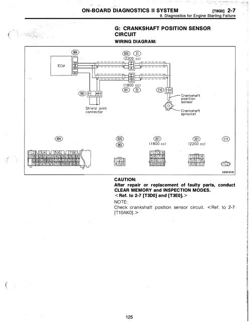
G: CRANKSHAFT POSITION SENSOR<br />
CIRCUIT<br />
WIRING DIAGRAM:<br />
_ <br />
__<br />
Shield joint<br />
connector<br />
(1800 cc)<br />
@ @<br />
@<br />
t---Crankshaft<br />
position<br />
, . sensor<br />
Crankshaft<br />
sprocket<br />
j<br />
i '2TU'"3'4T1J 56<br />
J 7 8 l n<br />
17181920 21 2212324 25 2627 282930]1<br />
<br />
45464748 49 15051 52 5354 555657<br />
71 7273747517677 78798081 82 83<br />
L<br />
L<br />
@<br />
®<br />
rum<br />
@<br />
@<br />
(1800 cc) (2200 cc)<br />
1 2 34<br />
56 78<br />
910 1112<br />
456 1314 1516<br />
H2M1618<br />
CAUTION:<br />
After repair or replacement of faulty parts, conduct<br />
CLEAR MEMORY <strong>and</strong> INSPECTION MODES.<br />
< Ref. to 2-7 [T3DO] <strong>and</strong> [T3EO]. ><br />
NOTE:<br />
Check crankshaft position sensor circuit. < Ref. to 2-7<br />
[T10AKO]. ><br />
125
Ii<br />
2-7 [TSHO] ON-BOARD DIAGNOSTICS II SYSTEM<br />
8. Diagnostics fo r Engine Starting Failure<br />
H: CAMSHAFT POSITION SENSOR CIRCUIT<br />
WIRING DIAGRAM:<br />
®<br />
a=iE--------------<br />
®®<br />
(2<br />
_ _ -__ -__ - _<br />
_-__<br />
-_""'"<br />
Shield joint<br />
connector<br />
(1800<br />
@ @<br />
Camshaft<br />
position<br />
sensor<br />
@ ? sprocket<br />
Icamshaft<br />
.<br />
® ®<br />
(1800 (2200<br />
f rL '3'4u 5 6 l '781.1,<br />
17 181920 21 22123 24 25 2627 28 2930\<br />
45 46 47 48 49 150 51 52 53 54 55 5657<br />
71 72 73 74 76 7778 79 80 81 82 83<br />
L<br />
fT'I2bl<br />
rnmm<br />
1 2 3 4<br />
56 78<br />
910 111 :1<br />
13 14 1J 16<br />
H2M1619<br />
CAUTION:<br />
After repair or replacement of faulty parts, conduct<br />
CLEAR MEMORY <strong>and</strong> INSPECTION MODES.<br />
< Ref. to 2-7 [T3DO] <strong>and</strong> [T3EO]. ><br />
NOTE:<br />
Check camshaft position sensor circuit. < Ref. to 2-7<br />
[T10AMO]. ><br />
126
ON-BOARD DIAGNOSTICS II SYSTEM [T8HO] 2-7<br />
8. Diagnostics for Engine Starting Failure<br />
MEMO:<br />
127
2-7 [T9AO] ON-BOARD DIAGNOSTICS II SYSTEM<br />
9. General Diagnostic Table<br />
9. General Diagnostic Table<br />
A: GENERAL DIAGNOSTICS TABLE WITH<br />
NONCONFORMITY SYMPTOM FOR ENGINE<br />
NOTE:<br />
Malfunction of parts other than those listed is also possible.<br />
<br />
Symptom<br />
1. Engine stalls during idling.<br />
2. Rough idling<br />
3. Engine does not return to idle.<br />
4. Poor acceleration<br />
S. Engine stalls or engine sags or hesitates at<br />
acceleration.<br />
Problem parts<br />
1) Idle air control solenoid valve<br />
2) Mass air flow sensor<br />
3) Ignition parts (*1)<br />
4) Engine coolant temperature sensor (*2)<br />
S) Crankshaft position sensor (*3)<br />
6) Camshaft position sensor (*3)<br />
7) EGR valve<br />
8) Fuel injection parts (*4)<br />
1) Idle air control solenoid valve<br />
2) Mass air flow sensor<br />
3) Engine coolant temperature sensor (*2)<br />
4) Ignition parts (*1)<br />
S) Air intake system (OS)<br />
6) Fuel injection parts (*4)<br />
7) Throttle position sensor<br />
8) Crankshaft position sensor (*3)<br />
9) Camshaft position sensor (*3)<br />
10) EGR valve<br />
11) Oxygen sensor<br />
12) Fuel pump <strong>and</strong> fuel pump relay<br />
1) Idle air control solenoid valve<br />
2) Engine coolant temperature sensor<br />
3) Accelerator cable (*6)<br />
4) Throttle position sensor<br />
S) Mass air flow sensor<br />
1) Mass air flow sensor<br />
2) Throttle position sensor<br />
3) Fuel injection parts (*4)<br />
4) Fuel pump <strong>and</strong> fuel pump relay<br />
S) Engine coolant temperature sensor (*2)<br />
6) Crankshaft position sensor (*3)<br />
7) Camshaft position sensor (*3)<br />
8) AIC switch <strong>and</strong> AIC cut relay<br />
9) Engine torque control signal circuit<br />
10) Ignition parts (*1)<br />
1) Mass air flow sensor<br />
2) Engine coolant temperature sensor (*2)<br />
3) Crankshaft position sensor (*3)<br />
4) Camshaft position sensor (*3)<br />
S) Purge control solenoid valve<br />
6) EGR valve<br />
7) Fuel injection parts (*4)<br />
8) Throttle position sensor<br />
9) Fuel pump <strong>and</strong> fuel pump relay<br />
128
ON-BOARD DIAGNOSTICS II SYSTEM<br />
[T9AO] 2-7<br />
9. General Diagnostic Table<br />
Symptom<br />
6. Surge<br />
Problem parts<br />
1) Mass air flow sensor<br />
2) Engine coolant temperature sensor (*2)<br />
3) Crankshaft position sensor (*3)<br />
4) Camshaft position sensor (*3)<br />
5) EGR valve<br />
6) Fuel injection parts (*4)<br />
7) Throttle position sensor<br />
8) Fuel pump <strong>and</strong> fuel pump relay<br />
1) Mass air flow sensor<br />
2) Engine coolant temperature sensor<br />
7. Spark knock 3) Knock sensor<br />
4) Fuel injection parts (*4)<br />
5) Fuel pump <strong>and</strong> fuel pump relay<br />
8. After burning in exhaust system<br />
*1: Check ignitor, ignition coil <strong>and</strong> spark plug.<br />
*2: Indicate the symptom occurring only in cold temperatures.<br />
*3: Ensure the secure installation.<br />
*4: Check fuel injector, fuel pressure regulator <strong>and</strong> fuel fi lter.<br />
*5: Inspect air leak in air intake system.<br />
*6: Adjust accelerator cable.<br />
1) Mass air flow sensor<br />
2) Engine coolant temperature sensor (*2)<br />
3) Fuel injection parts (*4)<br />
4) Fuel pump <strong>and</strong> fuel pump relay<br />
129
2-7 [T9BO] ON-BOARD DIAGNOSTICS II SYSTEM<br />
9, General Diagnostic Table<br />
B: GENERAL DIAGNOSTICS TABLE WITH<br />
NONCONFORMITY SYMPTOM FOR<br />
AUTOMATIC TRANSMISSION<br />
Symptom<br />
Starter does not rotate when select lever is in "P" or "N";<br />
starter rotates when select lever is in "R", "D", "3" or "2",<br />
Abnormal noise when select lever is in "P" or "N",<br />
Hissing noise occurs during st<strong>and</strong>ing start.<br />
Noise occurs while driving in "D1",<br />
Noise occUrs while driving in "D2",<br />
Noise occurs while driving in "D3",<br />
Noise occurs while driving in "D4",<br />
Engine stalls while shifting from one range to another.<br />
Vehicle moves when select lever is in "N",<br />
Shock occurs when select lever is moved from "N" to "D",<br />
Excessive time lag occurs when select lever is moved from<br />
li N" to "0".<br />
Shock occurs when select lever is moved from "N" to "R",<br />
Problem parts<br />
1) Inhibitor switch<br />
2) Select cable<br />
3) Select lever<br />
4) Starter motor <strong>and</strong> harness<br />
1) Strainer<br />
2) Duty solenoid C<br />
3) Oil pump<br />
4) Drive plate<br />
5) ATF level too high or too low<br />
1) Strainer<br />
2) ATF level too high or too low<br />
1) Final gear<br />
2) Planetary gear<br />
3) Reduction gear<br />
4) Differential gear oil level too high or too low<br />
1) Final gear<br />
2) Low & reverse brake<br />
3) Reduction gear<br />
4) Differential gear oil level too high or too low<br />
1) Final gear<br />
2) Low & reverse brake<br />
3) Planetary gear<br />
4) Reduction gear<br />
5) Differential gear oil level too high or too low<br />
1) Control valve<br />
2) Lock-<strong>up</strong> damper<br />
3) Engine performance<br />
1) Control unit<br />
2) Inhibitor switch<br />
3) Forward clutch<br />
1) Control module<br />
2) Accumulator ("N" to "D")<br />
3) Control valve<br />
4) ATF deterioration<br />
5) Dropping resistor<br />
1) Control module<br />
2) Control valve<br />
3) Forward clutch<br />
4) Duty solenoid A<br />
5) Forward clutch seal ring<br />
6) Front gasket transmission case<br />
1) Control module<br />
2) Accumulator (4A)<br />
3) Control valve<br />
4) ATF deterioration<br />
5) Dropping resistor<br />
130
ON-BOARD DIAGNOSTICS II SYSTEM [T980] 2-7<br />
9. General Diagnostic Table<br />
Symptom<br />
Excessive time lag occurs when select lever is moved from<br />
liN" to "R".<br />
Vehicle does not start in any shift range (engine stalls).<br />
/<br />
Vehicle does not start in any shift range (engine revving <strong>up</strong>).<br />
Vehicle does not start in "R" range only (engine revving <strong>up</strong>).<br />
Vehicle does not start in "R" range only (engine stalls).<br />
Vehicle does not start in "0", "3" or "2" range only (engine<br />
revving <strong>up</strong>).<br />
Vehicle does not start in "0", "3", "2" or "1" range only<br />
(engine revving <strong>up</strong>).<br />
Vehicle does not tarl in "0", "3", "2" or "1" range only<br />
(engine stalls).<br />
Vehicle starts in "R" range only (engine revving <strong>up</strong>).<br />
Acceleration during st<strong>and</strong>ing starts is poor (high stall rpm).<br />
Acceleration during st<strong>and</strong>ing starts is poor (lOW stall rpm).<br />
Acceleration is poor when select lever is in "0", "3" or "2"<br />
range (normal stall rpm).<br />
Problem parts<br />
1) Control valve<br />
2) Low & reverse clutch<br />
3) Reverse clutch<br />
4) Duty solenoid A<br />
5)<br />
Forward clutch seal ring<br />
6) Front gasket transmission case<br />
1) Parking brake mechanism<br />
2) Planetary gear<br />
1) Strainer<br />
2) Duty solenoid A<br />
3) Control valve<br />
4) Drive pinion<br />
5) Hypoid gear<br />
6) Axle shaft<br />
7) Differential gear<br />
8) Oil pump<br />
9) Input shaft<br />
10) Output shaft<br />
11) Planetary gear<br />
12) Drive plate<br />
13) ATF level too low<br />
14) Front gasket transmission case<br />
1) Select cable<br />
2) Select lever<br />
3) Control valve<br />
4) Low & reverse clutch<br />
5) Reverse clutch<br />
1) Forward clutch<br />
2) B<strong>and</strong> brake<br />
3) Planetary gear<br />
4) Parking brake mechanism<br />
1) Forward clutch<br />
2) One-way clutch (1-2)<br />
1) Forward clutch<br />
1) Reverse clutch<br />
1) Control valve<br />
1) Control valve<br />
2) Forward clutch<br />
3) Reverse clutch<br />
4) ATF level too low<br />
Front gasket transmission case<br />
5)<br />
1) Oil pump<br />
2) Torque converter one-way clutch<br />
3) Engine performance<br />
1) Control module<br />
2) Control valve<br />
3) High clutch<br />
4) Brake b<strong>and</strong><br />
5)<br />
Planetary gear<br />
131
2-7 [T980] ON-BOARD DIAGNOSTICS II SYSTEM<br />
9. General Diagnostic Table<br />
Symptom<br />
Acceleration is poor when select lever is in "R" (normal stall<br />
rpm).<br />
No shift occurs from 1st to 2nd gear.<br />
No shift occurs from 2nd to 3rd gear.<br />
No shift occurs from 3rd to 4th gear.<br />
Engine brake is not effected when select lever is in "3"<br />
range.<br />
Problem parts<br />
1) Control module<br />
2) Overrunning clutch<br />
3) High clutch<br />
4) Brake b<strong>and</strong><br />
5) Planetary gear<br />
1) Control module<br />
2) Vehicle speed sensor 1<br />
3) Vehicle speed sensor 2<br />
4) Throttle position sensor<br />
5) Shift solenoid 1<br />
6) Shift solenoid 2<br />
7) Control valve<br />
8) Brake b<strong>and</strong><br />
1) Control module<br />
2) Control valve<br />
3) High clutch<br />
4) One-way clutch (3-4)<br />
1) Control module<br />
2) Accumulator (3R)<br />
3) ATF temperature sensor<br />
4) Control valve<br />
5) B<strong>and</strong> brake<br />
1)<br />
Inhibitor switch<br />
2) Control module<br />
Throttle position sensor<br />
3)<br />
4) Control valve<br />
5) Shift solenoid 3<br />
Engine brake is not effected when select lever is in "3" or 1) Control valve<br />
"2" range. 2) Overrunning clutch<br />
Engine brake is not effected when select lever is in "1"<br />
range.<br />
Shift characteristics are erroneous.<br />
No lock-<strong>up</strong> occurs.<br />
Parking brake is not effected.<br />
Shift lever cannot be moved or is hard to move from "P"<br />
range.<br />
ATF spurts out.<br />
Differential oil spurts out.<br />
Differential oil level changes excessively.<br />
1) Control valve<br />
2) Low & reverse brake clutch<br />
1) Inhibitor switch<br />
2) Control module<br />
3) Vehicle speed sensor 1<br />
4) Vehicle speed sensor 2<br />
5) Throttle pOSition sensor<br />
6) Control valve<br />
1) Control module<br />
2) Throttle pOSition sensor<br />
3) ATF temperature sensor<br />
4) Control valve<br />
5) Lock-<strong>up</strong> facing<br />
6) Engine speed signal<br />
1) Select cable<br />
2) Select lever<br />
3) Parking mechanism<br />
1) ATF level too high<br />
1) Differential gear oil too high<br />
1) Seal pipe<br />
2) Double oil seal<br />
132
ON-BOARD DIAGNOSTICS II SYSTEM<br />
[T980] 2-7<br />
9. General Diagnostic Table<br />
Symptom<br />
Odor is produced from ATF s<strong>up</strong>ply pipe.<br />
Shock occurs from 1st to 2nd gear.<br />
Slippage occurs from 1st to 2nd gear.<br />
Shock occurs from 2nd to 3rd gear.<br />
Slippage occurs from 2nd to 3rd gear.<br />
Shock occurs from 3rd to 4th gear.<br />
Problem parts<br />
1) Transfer clutch<br />
2) Forward clutch<br />
3) Overrunning clutch<br />
4) High clutch<br />
5) B<strong>and</strong> brake<br />
6) Low & reverse clutch<br />
7) Reverse clutch<br />
8) Lock-<strong>up</strong> facing<br />
9) ATF deterioration<br />
1) Control module<br />
2) Throttle position snsor<br />
3) Accumulator (2A)<br />
4) ATF temperature sensor<br />
5) Duty solenoid A<br />
6) Control valve<br />
7) B<strong>and</strong> brake<br />
8) ATF deterioration<br />
9) Engine performance<br />
10) Dropping resistor<br />
1) Control module<br />
2) Throttle position sensor<br />
3) Accumulator (2A)<br />
4) ATF temperature sensor<br />
5) Duty solenoid A<br />
6) Control valve<br />
7) B<strong>and</strong> brake<br />
1) Control module<br />
2) Throttle position sensor<br />
3) Accumulator (3R)<br />
4) ATF temperature sensor<br />
5) Duty solenoid A<br />
6) Control valve<br />
7) High clutch<br />
8) B<strong>and</strong> brake<br />
9) ATF deterioration<br />
10) Engine performance<br />
11) Dropping resistor<br />
1) Control module<br />
2) Throttle position sensor<br />
3) Accumulator (3R)<br />
4) ATF temperature sensor<br />
5) Duty solenoid A<br />
6) Control valve<br />
7) High clutch<br />
8) B<strong>and</strong> brake<br />
1) Control module<br />
2) Throttle position sensor<br />
3) Accumulator<br />
4) ATF temperature sensor<br />
5) Duty solenoid A<br />
6) Control valve<br />
7) Overrunning clutch<br />
8) B<strong>and</strong> brake<br />
9) ATF deterioration<br />
10) Engine performance<br />
133
2-7 [T980] ON-BOARD DIAGNOSTICS II SYSTEM<br />
9. General Diagnostic Table<br />
Symptom<br />
Slippage occurs from 3rd to 4th gear.<br />
Shock occurs when select lever is moved from "3" to "2"<br />
range.<br />
Shock occurs when select lever is moved from "D" to "1"<br />
range.<br />
Shock occurs when select lever is moved from "2" to "1"<br />
range.<br />
Shock occurs when accelerator pedal is released at medium<br />
speeds.<br />
Vibration occurs during straight-forward operation.<br />
Vibration occurs during turns (tight corner "braking" phenomenon).<br />
Problem parts<br />
1) Control module<br />
2) Throttle position sensor<br />
3) Accumulator<br />
4) ATF temperature sensor<br />
5) Duty solenoid A<br />
6) Control valve<br />
7) B<strong>and</strong> brake<br />
1) Control module<br />
2) Throttle position sensor<br />
3) ATF temperature sensor<br />
4) Duty solenoid A<br />
5) Control valve<br />
6) Overrunning clutch<br />
7) B<strong>and</strong> brake<br />
8) A TF deterioration<br />
1) Control module<br />
2) Throttle position sensor<br />
3) ATF temperature sensor<br />
4) Duty solenoid A<br />
5) Control valve<br />
6) A TF deterioration<br />
7) Low & reverse brake_<br />
1) Control module<br />
2) Throttle position sensor<br />
3) ATF temperature sensor<br />
4) Duty solenoid A<br />
5) Control valve<br />
6) Low & reverse clutch<br />
7) ATF deterioration<br />
1) Control module<br />
2) Throttle position sensor<br />
3) ATF temperature sensor<br />
4) Duty solenoid A<br />
5) Control valve<br />
6) Lock-<strong>up</strong> damper<br />
7) Engine performance<br />
1) Control module<br />
2) Duty solenoid B<br />
3) Lock-<strong>up</strong> facing<br />
4) Lock-<strong>up</strong> damper<br />
1) Control module<br />
2) Vehicle speed sensor 1<br />
3) Vehicle speed sensor 2<br />
4) Throttle position sensor<br />
5) ATF temperature sensor<br />
6) Transfer clutch<br />
7) Transfer valve<br />
8) Duty solenoid C<br />
9) ATF deterioration<br />
134
ON-BOARD DIAGNOSTICS II SYSTEM<br />
[T9BO] 2-1<br />
9. General Diagnostic Table<br />
Symptom<br />
Front wheel slippage occurs during st<strong>and</strong>ing starts.<br />
Vehicle is not set in FWD mode.<br />
Select lever is hard to move.<br />
Select lever is too high to move (unreasonable resistance).<br />
Select lever slips out of operation during acceleration or<br />
while driving on rough terrain.<br />
Problem parts<br />
1) Control module<br />
2) Vehicle speed sensor 2<br />
3) FWD switch<br />
4) Throttle position sensor<br />
5) ATF temperature sensor<br />
6) Control valve<br />
7) Transfer clutch<br />
8) Transfer valve<br />
9) Transfer pipe<br />
10) Duty solenoid C<br />
11) Transfer clutch hub<br />
1) Control module<br />
2) FWD switch<br />
3) Transfer clutch<br />
4) Transfer valve<br />
5) Duty solenoid C<br />
1) Select cable<br />
2) Select lever<br />
3) Detent spring<br />
4) Manual plate<br />
i) Detent spring<br />
2) Manual plate<br />
1) Select cable<br />
2) Select lever<br />
3) Detent spring<br />
4) Manual plate<br />
135
2-7 [T10AO] ON-BOARD DIAGNOSTICS II SYSTEM<br />
10. Diag nostic Chart with Trouble Code<br />
10. Diagnostic Chart with Trouble Code<br />
A: DIAGNOSTIC TROUBLE CODE (DTC) LIST<br />
DTC Abbreviation<br />
No. (Subaru Select Monitor)<br />
Item<br />
Page<br />
P0101 QA-RLOW Mass air flow sensor circuit range/performance problem (low input) 140<br />
P0102 QA-LOW Mass air flow sensor circuit low input 142<br />
P0103 QA-HI Mass air flow sensor circuit high input 148<br />
P0106 PS-R2 Pressure sensor circuit range/performance problem 152<br />
P0107 P-SLOW Pressure sensor circuit low input 156<br />
P0108 P-SHI Pressure sensor circuit high input 160<br />
P01 16 TW-LOW Engine coolant temperature sensor circuit low input 166<br />
P01 17 TW-HI Engine coolant temperature sensor circuit high input 170<br />
P0121 TH-RHI Throttle position sensor circuit range/performance problem' (high input) 174<br />
P0122 THV-LOW Throttle position sensor circuit low input 176<br />
P0123 THV-HI Throttle position sensor circuit high input 182<br />
P0125 TW-CL Insufficient coolant temperature for closed loop fuel control 186<br />
P0130 F02-V Front oxygen sensor circuit malfunction 188<br />
P0133 F02-R Front oxygen sensor circuit slow response 192<br />
P0135 F02H Front oxygen sensor heater circuit malfunction 194<br />
P0136 R02-V Rear oxygen sensor circuit malfunction 198<br />
P0139 R02-R Rear oxygen sensor circuit slow response 202<br />
P0141 R02H Rear oxygen sensor heater circuit malfunction 204<br />
P0170 FUEL Fuel trim malfunction 208<br />
P0181 TNKT-F Fuel temperature sensor A circuit range/performance problem 214<br />
P0182 TNKT-LOW Fuel temperature sensor A circuit low input 216<br />
P0183 TNKT-HI Fuel temperature sensor A circuit high input 220<br />
P0261 INJ1 Fuel injector circuit low input - #1 224<br />
P0262 INJ1-HI Fuel injector circuit high input - #1 230<br />
P0264 INJ2 Fuel injector circuit low input - #2 224<br />
P0265 INJ2-HI Fuel injector circuit high input - #2 230<br />
P0267 INJ3 Fuel injector circuit low input - #3 224<br />
P0268 INJ3-HI Fuel injector circuit high input - #3 230<br />
P0270 INJ4 Fuel injector circuit low input - #4 224<br />
P0271 INJ4-HI Fuel injector circuit high input - #4 230<br />
P0301 MIS-1 Cylinder 1 misfire detected 234<br />
P0302 MIS-2 Cylinder 2 misfire detected 234<br />
P0303 MIS-3 Cylinder 3 misfire detected 234<br />
P0304 MIS-4 Cylinder 4 misfire detected 234<br />
P0325 KNOCK Knock sensor circuit malfunction 244<br />
P0335 CRANK Crankshaft position sensor circuit malfunction 248<br />
P0336 CRANK-R Crankshaft position sensor circuit range/performance problem 252<br />
P0340 CAM Camshaft position sensor circuit malfunction 254<br />
136
ON-BOARD DIAGNOSTICS II SYSTEM [T10AO] 2-7<br />
10. Diagnostic Chart with Trouble Code<br />
DTC Abbreviation<br />
No. (Subaru Select Monitor)<br />
P0341<br />
CAM-R<br />
P0400<br />
EGR<br />
P0403 EGRSOL<br />
P0420<br />
CAT<br />
P0440<br />
EVAP<br />
P0441<br />
CPC-F<br />
P0443<br />
CPC<br />
P0446 VCMSOL-LO<br />
P0451 TNKP-F<br />
P0452 TN KP-LOW<br />
P0453 TNKP-HI<br />
P0461<br />
FLVL-R<br />
P0462 FLVL-LOW<br />
P0463 FLVL-HI<br />
P0500<br />
VSP<br />
P0505<br />
ISC<br />
P0506 ISC-RLOW<br />
P0507 ISC-RHI<br />
P0600<br />
-<br />
P0601<br />
RAM<br />
P0703<br />
ATBRK<br />
P0705<br />
ATRNG<br />
P0710<br />
ATF<br />
P0720<br />
ATVSP<br />
P0725<br />
ATNE<br />
P0731<br />
ATGR1<br />
P0732<br />
ATGR2<br />
P0733<br />
ATGR3<br />
P0734<br />
ATGR4<br />
P0740 ATLU-F<br />
P0743<br />
ATLU<br />
P0748<br />
ATPL<br />
P0753<br />
ATSFT1<br />
P0758<br />
ATSFT2<br />
P0760 ATOVR-F<br />
P0763<br />
ATOVR<br />
P1100 ST-SWOFF<br />
P1101<br />
N-SW<br />
P1 101 N-SWOFF<br />
P1 102<br />
BR<br />
Item<br />
Page<br />
Camshaft position sensor circuit range/performance problem 258<br />
Exhaust gas recirculation flow malfunction 260<br />
Exhaust gas recirculation circuit low input 266<br />
Catalyst system efficiency below threshold 270<br />
Evaporative emission control system malfunction 272<br />
Evaporative emission control system incorrect purge flow 276<br />
Evaporative emission control system purge control valve circuit low input 278<br />
Evaporative emission control system vent control low input 282<br />
Evaporative emission control system pressure sensor range/performance<br />
problem<br />
Evaporative emission control system pressure sensor low input 288<br />
Evaporative emission control system pressure sensor high input 294<br />
Fuel level sensor circuit range/performance problem 300<br />
Fuel level sensor circuit low input 302<br />
Fuel level sensor circuit high input 308<br />
Vehicle speed sensor malfunction 314<br />
Idle control system malfunction 316<br />
Idle control system RPM lower than expected 324<br />
Idle control system RPM higher than expected 326<br />
Serial communication link malfunction 328<br />
Internal control module memory check sum error 330<br />
Brake switch input malfunction 332<br />
Transmission range sensor circuit malfunction 336<br />
Transmission fluid temperature sensor circuit malfunction 355<br />
Output speed sensor (vehicle speed sensor 1) circuit malfunction 356<br />
Engine speed input circuit malfunction 357<br />
Gear 1 incorrect ratio 358<br />
Gear 2 incorrect ratio 358<br />
Gear 3 incorrect ratio 358<br />
Gear 4 incorrect ratio 358<br />
Torque converter clutch system malfunction 362<br />
Torque converter clutch system electrical 366<br />
Pressure control solenoid electrical 367<br />
Shift solenoid A electrical 368<br />
Shift solenoid B electrical 369<br />
Shift solenoid C malfunction 370<br />
Shift solenoid C electrical 374<br />
Starter switch circuit low input 376<br />
Neutral position switch circuit malfunction [MT vehicles] 378<br />
Neutral pOSition switch circuit high input [AT vehicles] 382<br />
Pressure sources switching solenoid valve circuit low input 388<br />
286<br />
137
2-7 [T10AO] ON-BOARD DIAGNOSTICS II SYSTEM<br />
10. Diagnostic Chart with Trouble Code<br />
DTC Abbreviation<br />
No. (Subaru Select Monitor)<br />
Item<br />
P1 103 TRQ Engine torque control signal circuit malfunction<br />
P1120 ST-SWON Starter switch circuit high input<br />
P1121 N-SWON Neutral position switch circuitJow input [AT vehicles]<br />
P1122 BR-HI Pressure sources switching solenoid valve circuit high input<br />
P1141 QA-RHI Mass air flow sensor circuit range/performance problem (high input)<br />
P1142 TH-RLOW Throttle position sensor circuit range/performance problem (low input)<br />
P1143 PS-RLOW Pressure sensor circuit range/performance problem (low input)<br />
P1144 PS-RHI Pressure sensor circuit range/performance problem (high input)<br />
P1400 PCVSOL-LO Fuel tank pressure control solenoid valve circuit low input<br />
P1420 PCVSOL-HI Fuel tank pressure control solenoid valve circuit high input<br />
P1421 EGRSOL-HI Exhaust gas recirculation circuit high input<br />
P1422 CPC-HI Evaporative emission control system purge control valve circuit high input<br />
P1423 VCMSOL-HI Evaporative emission control system vent control high input<br />
P1440 PCV-FLOW Fuel tank pressure control system function problem (low input)<br />
P1441 PCV-FHI Fuel tank pressure control system function problem (high input)<br />
P1442 FLVL-R2 Fuel level sensor circuit range/performance problem 2<br />
P1500 FAN-1 Radiator fan relay 1 circuit low input<br />
P1502 FAN-F Radiator fan function problem<br />
P1507 ISC-SHI Idle control system malfunction (fail-safe)<br />
P1520 FAN-1HI Radiator fan relay 1 circuit high input<br />
P1540 VSP-S Vehicle speed sensor malfunction 2<br />
P1700 ATTH Throttle position sensor circuit malfunction for automatic transmission<br />
P1701 ATCRS Cruise control set signal circuit malfunction for automatic transmission<br />
P1702 ATDIAG-LO Automatic transmission diagnosis input signal circuit low input<br />
P1722 ATDIAG-HI Automatic transmission diagnosis input signal circuit high input<br />
P1742 ATDIAG-2 Automatic transmission diagnosis input signal circuit malfunction<br />
Page<br />
392<br />
396<br />
398<br />
402<br />
406<br />
408<br />
410<br />
414<br />
416<br />
420<br />
424<br />
428<br />
432<br />
436<br />
440<br />
444<br />
446<br />
450<br />
452<br />
454<br />
458<br />
460<br />
462<br />
464<br />
468<br />
472<br />
138
ON-BOARD DIAGNOSTICS II SYSTEM [T10AO] 2-7<br />
10. Diagnostic Chart with Trouble Code<br />
MEMO:<br />
139
2-7 [T1080] ON-BOARD DIAGNOSTICS II SYSTEM<br />
10. Diagnostic Chart with Trouble Code<br />
OBD<br />
POIOl<br />
(FBI )<br />
<br />
B: DTC P0101<br />
- MASS AIR FLOW SENSOR CIRCUIT<br />
RANGE/PERFORMANCE PROBLEM<br />
(LOW INPUT) -<br />
DTC DETECTING CONDITION:<br />
.. Two consecutive driving cycles with fault<br />
B2M1056<br />
----<br />
TROUBLE SYMPTOM:<br />
.. Erroneous idling<br />
.. Engine stalls .<br />
.. Poor driving performance<br />
WIRING DIAGRAM:<br />
Ma in relay<br />
=<br />
®<br />
S EeM· 7<br />
®
ON-BOARD DIAGNOSTICS II SYSTEM [T1081] 2-7<br />
10. Diagnostic Chart with Trouble Code<br />
1 1081 I CHECK DTC P0102 OR P0103 ON DISPLAY.<br />
<br />
: Does the Subaru select monitor or OBD-II<br />
general scan tool indicate DrC P0102 or<br />
P0103?<br />
6- Inspect DTC P0102 or P0103 using "10. Diagnostics<br />
Chart with Trouble Code". < Ref. to 2-7<br />
[T10AO] . ><br />
NOTE:<br />
In this case, it is not necessary to inspect DTC P0101 .<br />
C§) : Replace mass air flow sensor.<br />
141
2-7 [T10CO] ON-BOARD DIAGNOSTICS II SYSTEM<br />
10. Diagnostic Chart with Trouble Code<br />
OBD<br />
POI02<br />
(FBI )<br />
<br />
C: DTC P0102<br />
- MASS AIR FLOW SENSOR CIRCUIT lOW<br />
INPUT -<br />
DTC DETECTING CONDITION:<br />
• Immediately at fault recognition<br />
B2M1058<br />
TROUBLE SYMPTOM:<br />
• Erroneous idling<br />
• Engine stalls.<br />
• Poor driving performance<br />
WIRING DIAGRAM:<br />
Ma in relay<br />
=<br />
,.-------------------------------------------------------,<br />
_____________________________________________________ I<br />
ID" I<br />
I I<br />
I<br />
I I<br />
"<br />
Mass air<br />
flow<br />
sensor<br />
f-----,: :<br />
--QDf--------e$<br />
® ® S8F-2<br />
§m2<br />
3 4<br />
5<br />
@<br />
H2M1620<br />
CAUTION:<br />
After repair or replacement of faulty parts, conduct<br />
CLEAR MEMORY <strong>and</strong> INSPECTION MODES.<br />
< Ref. to 2-7 [T3DO] <strong>and</strong> [T3EO]. ><br />
142
ON-BOARD DIAGNOSTICS II SYSTEM [T10C1] 2-7<br />
10. Diagnostic Chart with Trouble Code<br />
10C1<br />
CONNECT SUBARU SELECT MONITOR OR<br />
THE OBD-II GENERAL SCAN TOOL, AND<br />
READ DATA.<br />
1) Turn ignition switch to OFF.<br />
2) Connect Subaru Select Monitor or the OBO-II general<br />
scan tool to data link connector.<br />
3) Turn ignition switch to ON <strong>and</strong> Subaru Select Monitor<br />
or the OBO-II general scan tool switch to ON.<br />
4) Start engine.<br />
QA<br />
1 . 67g / s<br />
( F06 )<br />
2.02V<br />
B2M04B1<br />
5) Read data on Subaru Select Monitor or OBO-II general<br />
scan tool.<br />
.. Subaru Select Monitor<br />
Designate mode using function key.<br />
Function mode: FOG<br />
.. F06: Mass air flow <strong>and</strong> voltage input from mass air flow<br />
sensor are shown on display at the same time.<br />
: Is the value equal to or more than 1.3 g/sec<br />
or 0.3 V <strong>and</strong> equal to or less than 250 g/sec<br />
or 5.0 V in function mode FOG?<br />
Probable cause: Poor connect of connectors, circuit <strong>and</strong><br />
grounding line.<br />
Gr::!: : Even if MIL lights <strong>up</strong>, the circuit has returned to a<br />
normal condition at this time. A temporary poor<br />
contact of the connector or harness may be the<br />
cause. Repair harness or connector in the mass<br />
air flow sensor.<br />
NOTE:<br />
In this case, repair the following:<br />
.. Open or ground short circuit in harness between mass<br />
air flow sensor <strong>and</strong> ECM connector<br />
.. Poor contact in mass air flow sensor or ECM con nector<br />
C§) : Go to step 10C2.<br />
143
2-7 [T10C2] ON-BOARD DIAGNOSTICS II SYSTEM<br />
10. Diagnostic Chart with Trouble Code<br />
'---___________ B2 MO 532A<br />
___ CHECK INPUT SIGNAL FOR ECM. (USING<br />
10C2 VOLTAGE METER AND SUBARU SELECT<br />
MONITOR.)<br />
1) Measure voltage between ECM con nector <strong>and</strong> chassis<br />
ground while engine is idling.<br />
Connector & terminal<br />
(884) No. 5 (+) - Chassis ground (-):<br />
: Is the voltage less than 0.3 V?<br />
... Cv Go to step 10C3.<br />
C§ : Go to next step 2).<br />
QA ( F06 )<br />
1 . 67g / s 2.02V<br />
B2M0481<br />
2) Measure voltage between ECM connector <strong>and</strong> chassis<br />
ground while engine is idling.<br />
: Does the voltage change more than 0.3 V by<br />
shaking harness <strong>and</strong> connector of ECM while<br />
monitoring the value with Subaru select<br />
monitor?<br />
Repair poor contact in ECM con nector.<br />
C£D :<br />
C§ :<br />
Contact with SOA service.<br />
NOTE:<br />
Inspection by DTM is required, because probable cause is<br />
deterioration of multiple parts.<br />
10C3<br />
CHECK POWER SUPPLY TO MASS AIR<br />
FLOW SENSOR.<br />
1) Turn ignition switch to OFF.<br />
2) Disconnect connector from mass air flow sensor.<br />
3) Turn ignition switch to ON.<br />
4) Measure voltage between mass air flow sensor connector<br />
<strong>and</strong> engine ground.<br />
B2M0645A<br />
144
12 Lf3'7"<br />
1718192021222<br />
15 647148119150<br />
71 2 3174175 6'<br />
L<br />
®<br />
ON-BOARD DIAGNOSTICS II SYSTEM [T10C4] 2-7<br />
10. Diagnostic Chart with Trouble Code<br />
Connector & terminal<br />
(83) No. 1 (+) - Engine ground (-):<br />
: Is the voltage more than 10 V?<br />
0- Go to step 10C4.<br />
: Repair open circuit in harness between main<br />
relay <strong>and</strong> mass air flow sensor connector.<br />
56 7 8 l-1 '/ 10C4 CHECK HARNESS BETWEEN ECM AND<br />
MASS AIR FLOW SENSOR CONNECTOR.<br />
.<br />
125 (2627(282530 '--}-u<br />
,\<br />
<br />
3154155 15657 \<br />
71.1 l(a0(a1 8283<br />
®<br />
/<br />
r=r<br />
Q<br />
'-'-----"-<br />
82M1059A<br />
1112N'<br />
1) Turn ignition switch to OFF.<br />
2) Discon nect connector from ECM.<br />
3) Measure resistance of harness between ECM <strong>and</strong> mass<br />
air flow sensor connector.<br />
Connector & terminal<br />
(884) No. 5 - (83) No. 4:<br />
: Is the resistance less than 1 O?<br />
0- : Go to next step 4).<br />
: Repair harness <strong>and</strong> connector.<br />
NOTE:<br />
In this case, repair the following:<br />
• Open circuit in harness between ECM <strong>and</strong> mass air flow<br />
sensor connector<br />
• Poor contact in mass air flow sensor connector<br />
• Poor contact in ECM connector<br />
4) Measure resistance of harness between ECM <strong>and</strong> mass<br />
air flow sensor connector.<br />
Connector & terminal<br />
(884) No. 53 - (83) No. 3:<br />
: Is the resistance less than 1 O?<br />
: Go to step 10C5.<br />
: Repair harness <strong>and</strong> connector.<br />
NOTE:<br />
In this case, repair the following:<br />
• Open circuit in harness between ECM <strong>and</strong> mass air flow<br />
sensor connector<br />
• Poor contact in mass air flow sensor con nector<br />
• Poor contact in ECM connector<br />
145
2-7 [nOe5] ON-BOARD DIAGNOSTICS II SYSTEM<br />
10. Diagnostic Chart with Trouble Code<br />
B2M1060A<br />
10C5<br />
CHECK HARNESS BETWEEN ECM AND<br />
MASS AIR FLOW SENSOR CONNECTOR.<br />
Measure resistance of harness between ECM connector<br />
<strong>and</strong> chassis ground.<br />
Connector & terminal<br />
(884) No. 5 - Chassis ground:<br />
: Is the resistance more than 1 MO.?<br />
Gr<br />
:<br />
Replace mass air flow sensor.<br />
Repair ground short circuit in harness between<br />
ECM <strong>and</strong> mass air flow sensor con nector.<br />
146
ON-BOARD DIAGNOSTICS II SYSTEM [noes] 2-7<br />
10. Diagnostic Chart with Trouble Code<br />
MEMO:<br />
147
2-7 [T10DO] ON-BOARD DIAGNOSTICS II SYSTEM<br />
10. Diagnostic Chart with Trouble Code<br />
OBD<br />
POI03<br />
D: DTC P0103<br />
- MASS AIR FLOW SENSOR CIRCUIT HIGH<br />
INPUT -<br />
DTC DETECTING CONDITION:<br />
o Immediately at fault recognition<br />
B2M1061<br />
TROUBLE SYMPTOM:<br />
o Erroneous idling<br />
o Engine stalls.<br />
o Poor driving performance<br />
WIRING DIAGRAM:<br />
Main relay<br />
=<br />
-------------------------------------------------------,<br />
_____________________________________________________ I<br />
v --4QO--------e---,$<br />
I I<br />
I I I<br />
----,: :<br />
"<br />
_<br />
® @) SBF-2<br />
Mass air<br />
flow<br />
sensor<br />
<br />
tftij<br />
®<br />
H2M1620<br />
CAUTION:<br />
After repair or replacement of faulty parts, conduct<br />
CLEAR MEMORY <strong>and</strong> INSPECTION MODES.<br />
< Ref. to 2-7 [T3DO] <strong>and</strong> [T3EO]. ><br />
148
ON-BOARD DIAGNOSTICS II SYSTEM [T10D1] 2-7<br />
10. Diagnostic Chart with Trouble Code<br />
CONNECT SUBARU SELECT MONITOR OR<br />
1001 THE OBD-II GENERAL SCAN TOOL, AND<br />
READ DATA.<br />
1) Turn ignition switch to OFF.<br />
2) Connect Subaru Select Monitor or the OBO-II general<br />
scan tool to data link connector.<br />
3) Turn ignition switch to ON <strong>and</strong> Subaru Select Monitor<br />
or the OBO-II general scan tool switch to ON.<br />
4) Start engine.<br />
QA<br />
1 67g .<br />
/ s<br />
( F06 )<br />
2.02V<br />
82M0481<br />
5) Read data on Subaru Select Monitor or OBO-II general<br />
scan tool.<br />
• Subaru Select Monitor<br />
Designate mode using function key.<br />
Function mode: FOB<br />
• F06: Mass air flow <strong>and</strong> voltage input from 'mass air flow<br />
sensor are shown on display at the same time.<br />
C€HC3> : Is the value equal to or more than 1.3 g/sec<br />
or 0.3 V <strong>and</strong> equal to or less than 250 g/sec<br />
or 5.0 V in function mode FOB?<br />
Probable cause: Poor connect of connectors, circuit <strong>and</strong><br />
grounding line.<br />
Cv : Even if MIL lights <strong>up</strong>, the circuit has returned to a<br />
normal condition at this time.<br />
@) : Go to step 1002.<br />
149
2-7 [T10D2] ON-BOARD DIAGNOSTICS II SYSTEM<br />
10. Diag nostic Chart with Trouble Code<br />
QA ( F06 )<br />
1 . 67g / s 2.02V<br />
B2M0481<br />
10D2<br />
CHECK HARNESS BETWEEN ECM AND<br />
MASS AIR FLOW SENSOR CONNECTOR.<br />
1) Turn ignition switch to OFF <strong>and</strong> Subaru Select Monitor<br />
or the OBO-II general scan tool switch to OFF.<br />
2) Disconnect connector from mass air flow sensor.<br />
3) Turn ignition switch to ON <strong>and</strong> Subaru Select Monitor<br />
or the OBO-II general scan tool switch to ON.<br />
4) Read data on Subaru select monitor or OBO-II general<br />
scan tool.<br />
.. Subaru Select Monitor<br />
Designate mode using function key.<br />
Function mode: FOG<br />
: Is the value more than 250 g/sec or 5 V in<br />
function mode FOG?<br />
C : Repair battery short circuit in harness between<br />
mass air flow sensor <strong>and</strong> ECM connector. After<br />
repair, replace ECM.<br />
@) : Replace mass air flow sensor .<br />
.. OBO-II general scan tool<br />
For detailed operation procedures, refer to OBO-II General<br />
Scan Tool Instruction Manual.<br />
150
ON-BOARD DIAGNOSTICS II SYSTEM [110D2] 2-7<br />
10. Diagnostic Chart with Trouble Code<br />
MEMO:<br />
151
2-7 [T10EO] ON-BOARD DIAGNOSTICS II SYSTEM<br />
10. Diagnostic Chart with Trouble Code<br />
OBD<br />
POI06<br />
E: DTC P0106<br />
- PRESSURE SENSOR CIRCUIT<br />
RANGE/PERFORMANCE PROBLEM -<br />
DTC DETECTING CONDITION:<br />
• Two consecutive driving cycles with fault<br />
B2M1062<br />
WIRING DIAGRAM:<br />
Pressure<br />
sensor<br />
@<br />
Shield joint<br />
connector<br />
*1 : 1800 cc<br />
*2 : 2000 cc<br />
Pressure sources<br />
switching solenoid<br />
va lve<br />
Main re lay<br />
®®<br />
SBF-2<br />
® ® ®<br />
(1800 cc) (2200 cc)<br />
§±i]2<br />
3 4<br />
5 6<br />
<br />
<br />
H2M1621<br />
CAUTION:<br />
After repair or replacement of faulty parts, conduct<br />
CLEAR MEMORY <strong>and</strong> INSPECTION MODES.<br />
< Ref. to 2-7 [T3DO] <strong>and</strong> [T3EO]. ><br />
152
ON-BOARD DIAGNOSTICS II SYSTEM [T10E2] 2-7<br />
10. Diagnostic Chart with Trouble Code<br />
10E1 CHECK DTC P0107, P0108, P1102 OR P1122<br />
ON DISPLAY.<br />
: Does the Subaru select monitor or OBD-II<br />
general scan tool indicate DTC P0107, P0108,<br />
P1102 OR P1122?<br />
C Inspect OTC P0107, P0108, P1 102 OR P1 122<br />
using "10. Diag nostics Chart with Trouble Code".<br />
< Ref. to 2-7 [T1 0AO]. ><br />
NOTE:<br />
In this case, it is not necessary to inspect OTC P0106.<br />
: Go to step 10E2.<br />
(<br />
Data link connector<br />
for Subaru select monitor <strong>and</strong><br />
aBO-II general scan tool )<br />
..<br />
..<br />
_<br />
_-,<br />
.<br />
\<br />
(<br />
Data link connector<br />
for<br />
MAN I:P<br />
Subaru select<br />
monitor only )<br />
; ""'''<br />
(F 2 1 )<br />
29kPa218mmHg<br />
82M0756<br />
/ 10E2 / CHECK DATA FOR CONTROL<br />
1) Turn ignition switch to OFF .<br />
2) Connect Subaru Select Monitor or the aBO-II general<br />
scan tool to data link connector.<br />
3) Turn ignition switch ON <strong>and</strong> Subaru Select Monitor or<br />
the aBO-II general scan tool switch ON.<br />
4) Start engine.<br />
5) Read data on Subaru Select Monitor or the aBO-II<br />
general scan tool.<br />
e Subaru Select Monitor<br />
Designate mode using function key.<br />
Function mode: F21 <strong>and</strong> F20<br />
e F21 : Display shows pressure signal value sent from the<br />
pressure sensor.<br />
e F20: Display shows pressure signal value sent from the<br />
pressure sensor.<br />
: Is the value more than 85 kPa in function<br />
mode F21 ?<br />
Go to step 10E3.<br />
: Go to next step 6).<br />
153
2-7 [T10E3] ON-BOARD DIAGNOSTICS II SYSTEM<br />
10. Diag nostic Chart with Trouble Code<br />
BARO.P (F 20)<br />
1 O OkPa752mmHg<br />
6) Read data an Subaru Select Manitar ar OBO-II general<br />
scan taal.<br />
: Is the value less than 32 kPa in function<br />
mode F20?<br />
Go. to' step 10E4.<br />
C§) : Go. to' step 7).<br />
B2M0755<br />
BARO.P (F 20)<br />
1 O OkPa752mmHg<br />
B2M0755<br />
7) Read data an Subaru Select Manitar or OBO-II general<br />
scan taal.<br />
: Is the value more than 133 kPa in function<br />
mode F20?<br />
Replace pressure sensar.<br />
: Repair paar cantact in pressure sensar<br />
can nectar, pressure saurces switching salenaid<br />
valve cannectar, <strong>and</strong> ECM canne.ctar.<br />
.. OBO-II general scan tao. I<br />
Far detailed aperatian procedures, refer to' the OBO-II<br />
General Scan Too.l Instructian Manual.<br />
1800 cc model<br />
'--____ _ __ ... ______ B 2M l _ _<br />
B2M1269B<br />
/ 10E3 / CHECK VACUUM HOSE.<br />
: ./s there a fault in vacuum hose?<br />
NOTE:<br />
Check the fallawing items .<br />
.. Oiscannectian af the vacuum hase fram pressure<br />
saurces switching salenaid valve to' intake manifald<br />
.. Hales in the vacuum hase between pressure saurces<br />
switching salenaid valve to' intake manifald<br />
_ -l .. Clagging af the vacuum hase between pressure<br />
saurces switching salenaid valve to' intake manifald<br />
.. Oiscannectian af the vacuum hase fram pressure sensar<br />
to' pressure saurces switching salenaid valve<br />
.. Hales in the vacuum hase between pressure sensar <strong>and</strong><br />
pressure saurces switching salenaid valve<br />
.. Clagging af the vacuum hase between pressure sensar<br />
<strong>and</strong> pressure saurces switching salenaid valve<br />
.. Clagging af the filter<br />
154<br />
Repair ar replace hases ar filter.<br />
Go. to' step 10E4.
ON-BOARD DIAGNOSTICS II SYSTEM [T10E4] 2-7<br />
10. Diagnostic Chart with Trouble Code<br />
H2M11338<br />
----<br />
10E4<br />
CHECK PRESSURE SOURCES SWITCHING<br />
SOLENOID VALVE.<br />
1) Turn ignition switch to OFF.<br />
2) Connect test mode connector.<br />
3) Turn ignition switch to ON.<br />
: Does pressure sources switching solenoid<br />
valve produce operating sound? (ON OFF<br />
each 1.5 sec.)<br />
NOTE:<br />
Pressure sources switching solenoid valve operation<br />
check can also be executed using Subaru Select Monitor<br />
(Function mode: FD10). For the procedure, refer to "COM<br />
PULSORY VALVE OPERATION CHECK MODE". < Ref. to<br />
2-7 [T3FO]. ><br />
Replace pressure sensor.<br />
: Replace pressure sources switching solenoid<br />
valve.<br />
155
2-7 [T10FO] ON-BOARD DIAGNOSTICS II SYSTEM<br />
10. Diagnostic Chart with Trouble Code<br />
OBD<br />
POI07<br />
(FBI )<br />
<br />
F: DTC P0107<br />
- PRESSURE SENSOR CIRCUIT lOW<br />
INPUT -<br />
DTC DETECTING CONDITION:<br />
• Immediately at fault recognition<br />
82M1064<br />
WIRING DIAGRAM:<br />
Pressure<br />
sensor<br />
@<br />
Shield joint<br />
connector<br />
*1: 1800 cc<br />
*2 : 2000 cc<br />
Pressure sources<br />
switching solenoid<br />
va lve<br />
Main relay<br />
@®<br />
SBF-2<br />
@<br />
@<br />
(1800 ccl<br />
a 45<br />
@<br />
(2200 ccl<br />
1lml1<br />
® @ ®<br />
rnIDl<br />
3 4<br />
@ m 5 6<br />
CAUTION:<br />
After repair or replacement of faulty parts,<br />
CLEAR MEMORY <strong>and</strong> INSPECTION MODES.<br />
< Ref. to 2-7 [T3DO] <strong>and</strong> [T3EO]. ><br />
®<br />
-5 678<br />
H2M1621<br />
conduct<br />
156
ON-BOARD DIAGNOSTICS II SYSTEM [T10F2] 2-7<br />
10. Diagnostic Chart with Trouble Code<br />
10F1<br />
CONNECT SUBARU SELECT MONITOR OR<br />
THE OBD-II GENERAL SCAN TOOL, AND<br />
READ DATA.<br />
1) Turn ignition switch to OFF.<br />
2) Con nect Subaru Select Monitor or the OBO-II general<br />
scan tool to data link connector.<br />
3) Turn ignition switch to ON <strong>and</strong> Subaru Select Monitor<br />
or the OBO-II general scan tool switch to ON.<br />
4) Start engine.<br />
MAN I.P (F 2 1 )<br />
29kPa218mmHg<br />
82M0756<br />
5) Read the data on Subaru Select Monitor or the OBO-II<br />
general scan tool.<br />
• Subaru Select Monitor<br />
DeSignate mode using function key.<br />
Function mode: F21<br />
• F21 : Display shows pressure signal value sent from<br />
pressure sensor.<br />
: Is the value less than 0 kPa in function mode<br />
F21?<br />
C Go to step 10F2.<br />
: Even if MIL lights <strong>up</strong>, the circuit has returned to<br />
a normal condition at this time.<br />
• OBO-II general scan tool<br />
For detailed operation procedu res, refer to the OBO-II<br />
General Scan Tool Instruction Manual.<br />
82M0535A<br />
10F2<br />
CHECK INPUT SIGNAL FOR ECM. (USING<br />
VOLTAGE METER AND SUBARU SELECT<br />
MONITOR.)<br />
1) Measure voltage between ECM con nector <strong>and</strong> chassis<br />
ground.<br />
Connector & terminal<br />
(884) No. 21 (+) - Chassis ground (-):<br />
: Is the voltage more than 4.5 V?<br />
Cvs) Go to next step 2).<br />
: Go to next .<br />
157
2-7 [T10F3] ON-BOARD DIAGNOSTICS II SYSTEM<br />
10. Diag nostic Chart with Trouble Code<br />
<br />
<br />
B2M0535A<br />
'/<br />
rl<br />
®<br />
8 7 U 6 5 r-r;r'3 U"2Ff"<br />
\\ 3C9827t 251241231222120191817<br />
'\<br />
57 565554/ I 2151 5C9B74645<br />
U--<br />
183182 81 80r 8177 176 5174 7 2 1<br />
P<br />
I.<br />
n<br />
'-<br />
u<br />
<br />
B2M0536A<br />
BARO.P (F 20)<br />
1 OOkPa752mmHg<br />
B2M0755<br />
ON-BOARD DIAGNOSTICS II SYSTEM [T10F4] 2-7<br />
10. Diagnostic Chart with Trouble Code<br />
Connector & terminal<br />
(82) No. 3 (+) - Engine ground (-):<br />
: Is the voltage more than 4.5 V?<br />
Go to next step 5).<br />
(§) : Repair open circuit in harness between ECM <strong>and</strong><br />
pressure sensor con nector.<br />
5) Turn ignition switch to OFF.<br />
® '/<br />
6) Disconnect connector from ECM.<br />
fru'3 '4 U 5 6 U 7 8 u1!----r"t-<br />
171819 212212 24251261272829301 <br />
L<br />
45146 '''496051 253546656 m iJu<br />
71 2 i 4 5176 7778 918C a 1 82 3<br />
'---<br />
/,<br />
@<br />
!ill]]]<br />
n<br />
-'-----"-<br />
Q<br />
B2M1065A<br />
7) Measure resistance of harness between ECM <strong>and</strong> pressure<br />
sensor connector.<br />
Connector & terminal<br />
(884) No. 20 - (82) No. 1:<br />
: Is the resistance less than 1 O?<br />
C : Go to next step 8).<br />
(§) :<br />
Repair harness <strong>and</strong> connector.<br />
NOTE:<br />
In this case, repair the following:<br />
• Open circuit in harness between ECM <strong>and</strong> pressure<br />
sensor connector<br />
.. Poor contact in shield joint connector (883)<br />
OBD0695A<br />
8) Measure resistance of harness between pressure sensor<br />
connector <strong>and</strong> engine ground.<br />
Connector & terminal<br />
(82) No. 2 - Engine ground:<br />
: Is the resistance more than 500 kO?<br />
C€ Go to step 10f4.<br />
(§) :<br />
Repair ground short circuit in harness between<br />
ECM <strong>and</strong> pressure sensor con nector.<br />
110f4 I CHECK POOR CONTACT.<br />
Check poor contact in pressure sensor con nector. < Ref.<br />
to FOREWORD [T3C1]. ><br />
: Is there poor contact in pressure sensor connector?<br />
2-7 [T10GO] ON-BOARD DIAGNOSTICS II SYSTEM<br />
10. Diagnostic Chart with Trouble Code<br />
OBD<br />
POI08<br />
(FBI )<br />
<br />
G: DTC P0108<br />
- PRESSURE SENSOR CIRCUIT HIGH<br />
INPUT -<br />
DTC DETECTING CONDITION:<br />
.. Immediately at fault recognition<br />
B2M1066<br />
WIRING DIAGRAM:<br />
Pressure<br />
sensor<br />
®<br />
Shield joint<br />
connector<br />
*1: 1800 cc<br />
Pressure sources<br />
switching so lenoid<br />
va lve<br />
Main relay<br />
*2: 2000 cc<br />
®® SBF-2<br />
®<br />
®<br />
(1800 ccl<br />
WI 4 6<br />
®<br />
(2200 ccl<br />
1lml1<br />
® @ @)<br />
<br />
3 4<br />
c@p g 5 6<br />
CAUTION:<br />
After repair or replacement of faulty parts,<br />
CLEAR MEMORY <strong>and</strong> INSPECTION MODES.<br />
< Ref. to 2-7 [T3DO] <strong>and</strong> [T3EO]. ><br />
®<br />
R 5678<br />
H2M1621<br />
conduct<br />
160
(<br />
Data link connector<br />
for Subaru select monitor <strong>and</strong><br />
·<br />
. OBD-II general scan tool )<br />
··· 1<br />
\<br />
ON-BOARD DIAGNOSTICS II SYSTEM [T10G2] 2-7<br />
(<br />
Data link connector<br />
for Subaru select<br />
monitor only )<br />
7."",,, i<br />
10G1<br />
10. Diagnostic Chart with Trouble Code<br />
CONNECT SUBARU SELECT MONITOR OR<br />
THE OBD-II GENERAL SCAN TOOL, AND<br />
READ DATA.<br />
1) Turn ignition switch to OFF.<br />
2) Connect Subaru Select Monitor or the OBO-II general<br />
scan tool to data link connector.<br />
3) Turn ignition switch to ON <strong>and</strong> Subaru Select Monitor<br />
or the OBO-II general scan tool switch to ON.<br />
4) Start engine.<br />
MANI.P (F 2 1 )<br />
29kPa218mmHg<br />
B2M0756<br />
5) Read the data on Subaru Select Monitor or the OBO-II<br />
general scan tool.<br />
• Subaru Select Monitor<br />
Designate mode using function key.<br />
Function mode: F21<br />
• F21: Display shows pressure signal value sent from<br />
pressure sensor.<br />
: Is the value more than 140 kPa in function<br />
mode F21?<br />
C) : Go to step 10GS.<br />
(§) : Go to step 10G2.<br />
• OBO-II general scan tool<br />
For detailed operation procedu res, refer to the OBO-II<br />
General Scan Tool Instruction Manual.<br />
82M0535A<br />
10G2<br />
CHECK INPUT SIGNAL FOR ECM. (USING<br />
VOLTAGE METER AND SUBARU SELECT<br />
MONITOR.)<br />
1) Measure voltage between ECM connector <strong>and</strong> chassis<br />
ground.<br />
Connector & terminal<br />
(884) No. 21 (+) - Chassis ground (-):<br />
: Is the voltage more than 4.5 V?<br />
Go to next step 2) .<br />
(§) : Go to next .<br />
161
2-7 [T10G2] ON-BOARD DIAGNOSTICS II SYSTEM<br />
10. Diagnostic Chart with Trouble Code<br />
82M0535A<br />
ON-BOARD DIAGNOSTICS II SYSTEM [T10G3] 2-7<br />
10.·Diagnostic Chart with Trouble Code<br />
OBD0693A<br />
10G3<br />
CHECK HARNESS BETWEEN ECM AND<br />
PRESSURE SENSOR CONNECTOR.<br />
1) Turn ignition switch to OFF.<br />
2) Disconnect connector from pressure sensor.<br />
3) Turn ignition switch to ON.<br />
4) Measure voltage between pressure sensor connector<br />
<strong>and</strong> engine ground.<br />
Connector & terminal<br />
(82) No. 3 (+ ) - Engine ground (-):<br />
: Is the voltage more than 4.5 V?<br />
. : Go to next step 5).<br />
C® : Repair open circuit in harness between ECM <strong>and</strong><br />
pressure sensor connector.<br />
884<br />
f'2rL '34"-' 5 6<br />
1718 9 21222:3124125 2<br />
456 74E49 05152<br />
71 2 :7 5 67778.<br />
L<br />
1/<br />
7 8 Lrl<br />
f---r1.<br />
27282930 8<br />
l 4 5 657<br />
'8081 823 '--I 1 2<br />
n<br />
Q<br />
...::....--.::.<br />
I.<br />
B2M0537A<br />
5) Turn ignition switch to OFF.<br />
6) Discon nect connector from ECM.<br />
7) Measure resistance of harness between ECM <strong>and</strong> pressure<br />
sensor connector.<br />
Connector & terminal<br />
(884) No. 26 - (82) No. 2:<br />
: Is the resistance less than 1 O?<br />
cY Go to next step 8) .<br />
C® : Repair open circuit in harness between ECM <strong>and</strong><br />
pressure sensor connector.<br />
8) Measure resistance of harness between ECM <strong>and</strong> pressure<br />
sensor connector.<br />
Connector & terminal<br />
(884) No. 20 - (82) No. 1:<br />
: Is the resistance less than 1 O?<br />
C : Go to step 10G4.<br />
C® : Repair harness <strong>and</strong> connector<br />
NOTE:<br />
In this case, repair the following:<br />
• Open circuit in harness between ECM <strong>and</strong> pressure<br />
sensor connector<br />
• Poor contact in shield joint connector (883)<br />
163
2-7 [T10G4] ON-BOARD DIAGNOSTICS II SYSTEM<br />
10. Diagnostic Chart with Trouble Code<br />
MANI.P (F 2 1 )<br />
29kPa218mmHg<br />
B2M0756<br />
110G4 I CHECK POOR CONTACT.<br />
Check poor contact in pressure sensor connector. < Ref.<br />
to FOREWORO [T3C1].><br />
ON-BOARD DIAGNOSTICS II SYSTEM [T10G5] 2-7<br />
10. Diagnostic Chart with Trouble Code<br />
MEMO:<br />
165
2-7 [nOHOl ON-BOARD DIAGNOSTICS II SYSTEM<br />
10. Diagnostic Chart with Trouble Code<br />
OBD (FBI )<br />
,<br />
PO 116 <br />
B2Ml067<br />
----<br />
H: DTC P01 16<br />
- ENGINE COOLANT TEMPERATURE<br />
SENSOR CIRCUIT LOW INPUT -<br />
DTC DETECTING CONDITION:<br />
• Immediately at fault recognition<br />
TROUBLE SYMPTOM:<br />
• Hard to start<br />
• Erroneous idling<br />
• Poor driving performance<br />
WIRING DIAGRAM:<br />
Engine coolant<br />
temperature sensor<br />
Shield joint<br />
connector<br />
f J'"3"'41lJ 5 6 J 7 8 L <br />
17 18 1920 21 22123 24 25 26 27 28 29 30 <br />
4 46 47 48 49150 51 52 53 54 55 56 57<br />
L<br />
71 72 73 74 75176 77 78 79 80 81 82 83<br />
*1 :@<br />
(1800 cc)<br />
,.....,<br />
1 2 34<br />
56 78<br />
910 11 12<br />
13 14 15 16<br />
*2 :@<br />
(2200 cc)<br />
*3 :@<br />
(1800 cc)<br />
ni2I3l<br />
<br />
*4 :@<br />
(2200 cc)<br />
m2f3rn<br />
<br />
®<br />
H2M1622<br />
CAUTION:<br />
After repair or replacement of faulty parts, conduct<br />
CLEAR MEMORY <strong>and</strong> INSPECTION MODES.<br />
< Ref. to 2-7 [TlDO] <strong>and</strong> [TlEO]. ><br />
166
ON-BOARD DIAGNOSTICS II SYSTEM [T10H2] 2-7<br />
10. Diagnostic Chart with Trouble Code<br />
10H1<br />
CONNECT SUBARU SELECT MONITOR OR<br />
THE OBD-II GENERAL SCAN TOOL, AND<br />
READ DATA.<br />
1) Turn ignition switch to OFF.<br />
2) Connect Subaru Select Monitor or the OBO-II general<br />
scan tool to data link connector.<br />
3) Turn ignition switch to ON <strong>and</strong> Subaru Select Monitor<br />
or OBO-II general scan tool switch to ON.<br />
4) Start engine.<br />
TW<br />
( F04 )<br />
176 O F<br />
B2M0479<br />
5) Read data on Subaru Select Monitor or OBO-II general<br />
scan tool.<br />
• Subaru Select Monitor<br />
Designate mode using function key.<br />
Function mode: F04<br />
• F04: Water temperature is indicated in 110C" <strong>and</strong> "°F".<br />
: Is the value greater than 150°C or 300°F in<br />
function mode F04?<br />
Cv : Go to step 10H2.<br />
C§) : Repair poor contact.<br />
NOTE:<br />
In this case, repair the following:<br />
• Poor contact in engine coolant temperature sensor<br />
• Poor contact in ECM<br />
• Poor contact in co<strong>up</strong>ling connector (B21)<br />
• OBO-II general scan tool<br />
For detailed operation procedures, refer to the OBO-II<br />
General Scan Tool Instruction Manual.<br />
10H2<br />
CHECK HARNESS BETWEEN ENGINE COOL-<br />
ANT TEMPERATURE SENSOR AND ECM<br />
CONNECTOR.<br />
1) Turn ignition switch to OFF.<br />
2) Remove air intake duct. < Ref. to 2-7 [W1AO] . ><br />
3) Remove idle air control solenoid valve by-pass air hose<br />
(2200 cc model).<br />
4) Discon nect connector from engine coolant temperature<br />
sensor.<br />
5) Turn ignition switch <strong>and</strong> Subaru Select Monitor or<br />
OBO-II general scan tool switch to ON.<br />
167
2-7 [T10H2] ON-BOARD DIAGNOSTICS II SYSTEM<br />
10. Diag nostic Chart with Trouble Code<br />
TW (F04 )<br />
176 O F<br />
B2M0479<br />
6) Read data on Subaru Select Monitor or the OBO-II<br />
general scan tool.<br />
• Subaru Select Monitor<br />
Designate mode using function key.<br />
Function mode: F04<br />
• F04: Water temperature is indicated in C 110 "<br />
<strong>and</strong> "°F".<br />
S : Is the value less than -40°C or -40°F in function<br />
mode F04?<br />
: Replace engine coolant temperature sensor.<br />
C® : Repair ground short circuit in harness between<br />
engine coolant temperature sensor <strong>and</strong> ECM connector.<br />
• OBO-II general scan tool<br />
For detailed operation procedures, refer to the OBO-II<br />
General Scan Tool Instruction Manual.<br />
168
ON-BOARD DIAGNOSTICS II SYSTEM [T10H2] 2-7<br />
10. Diagnostic Chart with Trouble Code<br />
MEMO:<br />
169
2-7 [T1010] ON-BOARD DIAGNOSTICS II SYSTEM<br />
10. Diagnostic Chart with Trouble Code<br />
L-<br />
OBD<br />
PO 117<br />
__ __ __ __ B2M106B<br />
______ __ ____ ____ <br />
I: DTC P0117<br />
- ENGINE COOLANT TEMPERATURE<br />
SENSOR CIRCUIT HIGH INPUT -<br />
DTC DETECTING CONDITION:<br />
.. Immediately at fault recognition<br />
TROUBLE SYMPTOM:<br />
.. Hard to start<br />
.. Erroneous idling<br />
.. Poor driving performance<br />
WIRING DIAGRAM:<br />
Engine coolant<br />
temperature sensor<br />
®<br />
Shield joint<br />
connector<br />
*1 :@<br />
(1800 cc)<br />
1 2 3 14<br />
56 7'8<br />
910 11 12<br />
13 14 1510<br />
*2 :@<br />
(2200 cc)<br />
*3 :@<br />
(1800 cc)<br />
ni2l3l<br />
<br />
*4 :@<br />
(2200 cc)<br />
m213T4l<br />
<br />
®<br />
H2M1622<br />
CAUTION:<br />
After repair or replacement of faulty parts, conduct<br />
CLEAR MEMORY <strong>and</strong> INSPECTION MODES.<br />
< Ref. to 2·7 [T3DO] <strong>and</strong> [T3EO]. ><br />
170
(<br />
Data link connector<br />
for Subaru select monitor <strong>and</strong><br />
OBD-II general scan tool )<br />
«· 1<br />
\<br />
ON-BOARD DIAGNOSTICS II SYSTEM [T1012] 2-7<br />
(<br />
Data link connector<br />
for Subaru select<br />
monitor only )<br />
7.M118"<br />
10. Diagnostic Chart with Trouble Code<br />
CONNECT SUBARU SELECT MONITOR OR<br />
1011 THE OBD-II GENERAL SCAN TOOL, AND<br />
READ DATA.<br />
1) Turn ignition switch to OFF.<br />
2) Connect Subaru Select Monitor or the OBo-1i general<br />
scan tool to data link connector.<br />
3) Turn ignition switch to ON <strong>and</strong> Subaru Select Monitor<br />
or OBo-11 general scan tool switch to ON.<br />
4) Start engine.<br />
TW<br />
( F04 )<br />
82M0479<br />
5) Read data on Subaru Select Monitor or OBo-1i general<br />
scan tool.<br />
• Subaru Select Monitor<br />
Designate mode using function key.<br />
Function mode: F04<br />
• F04: Water temperature is indicated in 11 0 C " <strong>and</strong> "°F".<br />
: Is the value less than -40°C or -40°F ;n function<br />
mode F04?<br />
C : Go to step 1m3.<br />
(§) : Repair poor contact.<br />
NOTE:<br />
In this case, repair the following:<br />
• Poor contact in engine coolant temperature sensor<br />
• Poor contact in ECM<br />
• Poor contact in co<strong>up</strong>ling connector (B21)<br />
• OBo-11 general scan tool<br />
For detailed operation procedu res, refer to the OBo-1i<br />
General Scan Tool Instruction Manual.<br />
1m2<br />
CHECK HARNESS BETWEEN ENGINE COOL-<br />
ANT TEMPERATURE SENSOR AND ECM<br />
CONNECTOR.<br />
1) Turn ignition switch to OFF.<br />
2) Remove air intake duct. <br />
3) Remove idle air control solenoid valve by-pass air hose.<br />
(2200 cc model)<br />
4) Disconnect connector from engine coolant temperature<br />
sensor.<br />
171
2-7 [T1013] ON-BOARD DIAGNOSTICS II SYSTEM<br />
10. Diagnostic Chart with Trouble Code<br />
":"<br />
CJ<br />
@<br />
ON-BOARD DIAGNOSTICS II SYSTEM [n0l3] 2-7<br />
10. Diagnostic Chart with Trouble Code<br />
OBD0697A<br />
2) Turn ignition switch to OFF.<br />
3) Measure resistance of harness between engine coolant<br />
temperature sensor connector <strong>and</strong> engine ground.<br />
Connector & terminal<br />
(EB) No. 2 - Engine ground:<br />
: Is the resistance less than 5 Q?<br />
(5r : Replace engine coolant temperature sensor.<br />
: Repair harness <strong>and</strong> connector.<br />
NOTE:<br />
In this case, repair the following:<br />
.. Open circuit in harness between ECM <strong>and</strong> engine coolant<br />
temperature sensor connector<br />
.. Poor contact in engine coolant temperature sensor<br />
connector<br />
.. Poor contact in ECM connector<br />
.. Poor contact in co<strong>up</strong>ling connector (821)<br />
.. Poor contact in shield joint con nector (883)<br />
173
2-7 [T10JO] ON-BOARD DIAGNOSTICS II SYSTEM<br />
10. Diagnostic Chart with Trouble Code<br />
OBD (FBI )<br />
POl2I <br />
B2M1069<br />
J: DTC P0121<br />
- THROTTLE POSITION SENSOR CIRCUIT<br />
RANGE/PERFORMANCE PROBLEM (HIGH<br />
INPUT) -<br />
DTC DETECTING CONDITION:<br />
• Two consecutive driving cycles with fault<br />
TROUBLE SYMPTOM:<br />
• Erroneous idling<br />
• Engine stalls.<br />
• Poor driving performance<br />
WIRING DIAGRAM:<br />
<br />
____<br />
@<br />
Shie ld joint<br />
connector<br />
®B<br />
__<br />
__<br />
__<br />
________<br />
21<br />
<br />
Thrott le<br />
position<br />
sensor<br />
*1 : @<br />
(1800 cc)<br />
1 2 134<br />
f 1'3"'4"" 56 J 78 L<br />
17 18 1920 21 22 2324 25 26 27 28 29 301\ 56 II Itl<br />
45 46 47 48 49 5051 52 5354 55 5657 91011 12<br />
71 72737475 767778 79 80 81 82 83 13141 16<br />
*2 : @<br />
(2200 *3 : @ *4 : @<br />
cc) (1800 cc) (2200<br />
rrf2t3l<br />
rm:mJ<br />
cc)<br />
m2i3T4l<br />
<br />
H2M1623<br />
CAUTION:<br />
After repair or replacement of faulty parts, conduct<br />
CLEAR MEMORY <strong>and</strong> INSPECTION MODES.<br />
< Ref. to 2-7 [T3DO] <strong>and</strong> [T3EO]. ><br />
174
ON-BOARD DIAGNOSTICS II SYSTEM [T10J1] 2-7<br />
10. Diagnostic Chart with Trouble Code<br />
/ 10J1<br />
/ CHECK DTC P0122 OR P0123 ON DISPLAY.<br />
: Does the Subaru select monitor or OBD-II<br />
general scan tool indicate D rC P0122 or<br />
P0123?<br />
Inspect DTC P0122 or P0123 using "10. Diagnostics<br />
Chart with Trouble Code". < Ref. to 2-7<br />
[T1 0AO] . ><br />
NOTE:<br />
In ' this case, it is not necessary to inspect DTC P01 21.<br />
: Replace throttle position sensor.<br />
175
2-7 [T10KO] ON-BOARD DIAGNOSTICS II SYSTEM<br />
10. Diagnostic Chart with Trouble Code<br />
OBD (FBI )<br />
POI22 <br />
B2M1070<br />
K: DTC P0122<br />
- THROTTLE POSITION SENSOR CIRCUIT<br />
LOW INPUT -<br />
DTC DETECTING CONDITION:<br />
• Immediately at fault recognition<br />
TROUBLE SYMPTOM:<br />
• Erroneous idling<br />
• Engine stalls.<br />
• Poor driving performance<br />
WIRING DIAGRAM:<br />
Shield joint<br />
connector<br />
®B<br />
== @ __ ====== rn ®<br />
<br />
E2 ________<br />
Thrott<br />
le<br />
position<br />
sensor<br />
* 1 : @<br />
(1800 ee)<br />
*2 : @<br />
(2200 cd<br />
*3 : @<br />
(1800 ee)<br />
*4 : @<br />
(2200 ee)<br />
34<br />
5678<br />
910 11 12<br />
13 14 15 16<br />
1 2<br />
ni2t3l<br />
[ill]Q]<br />
m2f3r4l<br />
<br />
H2M1623<br />
CAUTION:<br />
After repair or replacement of faulty parts, conduct<br />
CLEAR MEMORY <strong>and</strong> INSPECTION MODES.<br />
< Ref. to 2-7 [T3DO] <strong>and</strong> [T3EO]. ><br />
176
ON-BOARD DIAGNOSTICS II SYSTEM [T10K1] 2-7<br />
10. Diagnostic Chart with Trouble Code<br />
10K1<br />
CONNECT SUBARU SELECT MONITOR OR<br />
THE OBD-II GENERAL SCAN TOOL, AND<br />
READ DATA.<br />
1) Turn ignition switch to OFF.<br />
2) Connect Subaru Select Monitor or the OBO-II general<br />
scan tool to data link connector.<br />
3) Turn ignition switch to ON <strong>and</strong> Subaru Select Monitor<br />
or OBO-II general scan tool switch to ON.<br />
4) Start engine.<br />
THV<br />
(F07 )<br />
0% O. 21V<br />
B2M0482<br />
5) Read data on Subaru Select Monitor or OBO-II general<br />
scan tool.<br />
• Subaru Select Monitor<br />
DeSignate mode using function key.<br />
Function mode: F07<br />
• F07: Throttle position sensor output signal is indicated.<br />
: Is the value less than 0.1 V in function mode<br />
F07?<br />
6') Go to step 10G2.<br />
C® : Even if MIL lights <strong>up</strong>, the circuit has returned to<br />
a normal condition at this time. A temporary poor<br />
contact of the con nector may be the cause.<br />
NOTE:<br />
In this case, repair the following:<br />
• Poor contact in throttle position sensor connector<br />
• Poor contact in ECM connector<br />
• Poor contact in co<strong>up</strong>ling connector (B21)<br />
• OBO-II general scan tool<br />
For detailed operation procedu res, refer to the OBO-II<br />
General Scan Tool Instruction Manual.<br />
177
2-7 [T10K2] ON-BOARD DIAGNOSTICS II SYSTEM<br />
10. Diagnostic Chart with Trouble Code<br />
CHECK INPUT SIGNAL FOR ECM. (USING<br />
10K2 VOLTAGE METER AND SUBARU SELECT<br />
MONITOR.)<br />
1) Measure voltage between ECM connector <strong>and</strong> chassis<br />
ground while throttle valve is fully closed.<br />
Connector & terminal<br />
(884) No. 21 (+) - Chassis ground (-):<br />
: Is the voltage more than 4.5 V?<br />
@: : Go to next step 2).<br />
(§) : Go to next .<br />
: Does the voltage change more than 4.5 V by<br />
shaking harness <strong>and</strong> connector of ECM while<br />
monitoring the value with voltage meter?<br />
ON-BOARD DIAGNOSTICS II SYSTEM [T10K3] 2-7<br />
10. Diagnostic Chart with Trouble Code<br />
OBD0700A<br />
10K3<br />
CHECK HARNESS BETWEEN ECM AND<br />
THROTTLE POSITION SENSOR CONNEC<br />
TOR.<br />
1) Turn ignition switch to OFF.<br />
2) Disconnect connectors from throttle position sensor.<br />
3) Turn ignition switch to ON.<br />
4) Measure voltage between throttle position sensor connector<br />
<strong>and</strong> engine ground.<br />
Connector & terminal<br />
(E13) No. 3 (+) - Engine ground (-):<br />
: Is the voltage more than 4.5 V?<br />
Cv : Go to next step 5).<br />
C§) : Repair harness <strong>and</strong> connector.<br />
NOTE:<br />
In this case, repair the following:<br />
• Open circuit in harness between throttle position sensor<br />
<strong>and</strong> ECM connector<br />
• Poor contact in throttle position sensor connector<br />
• Poor contact in ECM connector<br />
• Poor contact in co<strong>up</strong>ling connector (821)<br />
B2M0543A<br />
5) Turn ignition switch to OFF.<br />
6) Measure resistance of harness between ECM connector<br />
<strong>and</strong> throttle position sensor connector.<br />
Connector & terminal<br />
(884) No. 6 - (E13) No. 2:<br />
: Is the resistance less than 1 Q?<br />
Cv : Go to next step 7).<br />
C§) : Repair harness <strong>and</strong> connector.<br />
NOTE:<br />
In this case, repair the following:<br />
• Open circuit in harness between throttle position sensor<br />
<strong>and</strong> ECM connector<br />
• Poor contact in ECM connector<br />
• Poor contact in throttle position sensor connector<br />
• Poor contact in co<strong>up</strong>ling connector (821)<br />
179
2-7 [T10K4] ON-BOARD DIAGNOSTICS II SYSTEM<br />
10. Diag nostic Chart with Trouble Code<br />
OBD0702A<br />
7) Measure resistance of harness between throttle position<br />
sensor connector <strong>and</strong> engine ground.<br />
Connector & terminal<br />
(E13) No. 2 - Engine ground:<br />
: Is the resistance less than 10 O?<br />
Cv Repair ground short circuit in harness between<br />
throttle position sensor <strong>and</strong> ECM connector.<br />
@) Go to step 10K4.<br />
110K4 ICHECK POOR CONTACT.<br />
Check poor contact in throttle position sensor connector.<br />
< Ref. to FOREWORD [T3C1]. ><br />
: Is there poor contact in throttle position sensor<br />
connector?<br />
Cv Repair poor contact in throttle position sensor<br />
connector.<br />
@) Replace throttle position sensor.<br />
180
ON-BOARD DIAGNOSTICS II SYSTEM [T10K4] 2-7<br />
10. Diagnostic Chart with Trouble Code<br />
MEMO:<br />
181
2-7 [T10LO] ON-BOARD DIAGNOSTICS II SYSTEM<br />
10. Diagnostic Chart with Trouble Code<br />
OBD<br />
POI23<br />
(FBI )<br />
<br />
l: DTC P0123<br />
- THROTTLE POSITION SENSOR CIRCUIT<br />
HIGH INPUT -<br />
DTC DETECTING CONDITION:<br />
• Immediately at fault recognition<br />
B2M1071<br />
TROUBLE SYMPTOM:<br />
• Erroneous idling<br />
• Engine stalls.<br />
• Poor driving performance<br />
WIRING DIAGRAM:<br />
Shield joint<br />
connector<br />
®B<br />
®<br />
Throttle<br />
position<br />
sensor<br />
f '2ru'34L 5 6 ..J/'Sru7<br />
17 18 1920 21 22 23 24 25 26 27 28 29 30 1\<br />
45 46 47 48 49 .50 51 52 5354 55 56 157<br />
7172 7374 75 7677 78 79 80 81 82 83<br />
L<br />
* 1 :@<br />
(1800 cc)<br />
34<br />
5678<br />
1 2<br />
910 11 12<br />
1314 15 16<br />
*2 : @<br />
(2200 cc)<br />
*3 : @<br />
(1800 cc)<br />
ni2I3l<br />
till1Q]<br />
*4 :@<br />
(2200 cc)<br />
rn2i3T4l<br />
<br />
H2M1623<br />
CAUTION:<br />
After repair or replacement of faulty parts, conduct<br />
CLEAR MEMORY <strong>and</strong> INSPECTION MODES.<br />
< Ref. to 2-7 [T3DO] <strong>and</strong> [T3EO]. ><br />
182
ON-BOARD DIAGNOSTICS II SYSTEM [T10l1] 2-7<br />
10. Diagnostic Chart with Trouble Code<br />
10L1<br />
CONNECT SUBARU SELECT MONITOR OR<br />
THE OBD-II GENERAL SCAN TOOL, AND<br />
READ DATA.<br />
1) Turn ignition switch to OFF.<br />
2) Con nect Subaru Select Monitor or the OBO-II general<br />
scan tool to data link connector.<br />
3) Turn ignition switch to ON <strong>and</strong> Subaru Select Monitor<br />
or OBO-II general scan tool switch to ON.<br />
4) Start engine.<br />
THV<br />
( F07 )<br />
0% O. 21V<br />
B2M04B2<br />
5) Read data on Subaru Select Monitor or OBO-II general<br />
scan tool.<br />
.. Subaru Select Monitor<br />
Designate mode using function key.<br />
Function mode: F07<br />
.. FO?: Throttle position sensor output signal is indicated.<br />
: Is the value more than 4.9 V in function<br />
mode F07?<br />
Cv : Go to step 10L2.<br />
C® : Even if MIL lights <strong>up</strong>, the circuit has returned to a<br />
normal condition at this time. A temporary poor<br />
contact of the connector may be the cause.<br />
NOTE:<br />
In this case, repair the following:<br />
.. Poor contact in throttle position sensor connector<br />
.. Poor contact in ECM connector<br />
.. Poor contact in co<strong>up</strong>ling con nector (B21)<br />
.. OBO-II general scan tool<br />
For detailed operation procedu res, refer to the OBO-II<br />
General Scan Tool Instruction Manual.<br />
183
2-7 [T10L2] ON-BOARD DIAGNOSTICS II SYSTEM<br />
10. Diagnostic Chart with Trouble Code<br />
OBD0703A<br />
10L2<br />
CHECK HARNESS BETWEEN THROTTLE<br />
POSITION SENSOR AND BODY CONNEC·<br />
TOR.<br />
1) Turn ignition switch to OFF.<br />
2) Disconnect connector from throttle position sensor.<br />
3) Measure resistance of harness between throttle position<br />
sensor connector <strong>and</strong> engine ground.<br />
Connector & terminal<br />
(E13) No. 1 - Engine ground:<br />
: Is the resistance less than 5 O?<br />
C) : Go to next step 4).<br />
C® : Repair harness <strong>and</strong> connector.<br />
NOTE:<br />
In this case, repair the following:<br />
.. Open circuit in harness between throttle position sensor<br />
<strong>and</strong> ECM connector<br />
.. Poor contact in shield joint connector (883)<br />
OBD0704A<br />
4) Turn ignition switch to ON.<br />
5) Measure voltage between throttle position sensor connector<br />
<strong>and</strong> engine ground.<br />
Connector & terminal<br />
(E13) No. 2 (+) - Engine ground (-):<br />
: Is the voltage more than 4.9 V?<br />
0' : Repair battery short circuit in harness between<br />
throttle position sensor <strong>and</strong> ECM connector. After<br />
repair, replace ECM.<br />
C®<br />
Replace throttle position sensor.<br />
184
ON-BOARD DIAGNOSTICS II SYSTEM [T10l2] 2-7<br />
10. Diagnostic Chart with Trouble Code<br />
MEMO:<br />
185
2-7 [T10MO] ON-BOARD DIAGNOSTICS II SYSTEM<br />
10. Diagnostic Chart with Trouble Code<br />
OBD (FB I)<br />
M: DTC P0125<br />
- INSUFFICIENT COOLANT TEMPERATURE<br />
FOR CLOSED LOOP FUEL CONTROL -<br />
DTC DETECTING CONDITION:<br />
POI25 <br />
• Two consecutive driving cycles with fault<br />
0800191<br />
TROUBLE SYMPTOM:<br />
• Engine would not return to idling.<br />
WIRING DIAGRAM:<br />
Engine coolant<br />
temperature sensor<br />
Shield joint<br />
connector<br />
*1 :@<br />
(1800 eel<br />
-"',<br />
f '2fL 3'4" J 5 6 u7'SH i 1 2 3 4<br />
17181920 21 22 2324 2526127 2829 30 \ 56 j l/j<br />
45 464748 49 50 51 5253154 55 56<br />
910<br />
71 73 74 75 76 7778 7918081 82 83<br />
13 141 16<br />
L<br />
57<br />
ll 1z<br />
*2 :@<br />
(2200 eel<br />
*3 :@<br />
(1800 eel<br />
rri'2I3l<br />
[ill]Q]<br />
*4 :@<br />
(2200 eel<br />
rn2i3r4J<br />
<br />
®<br />
H2M1622<br />
CAUTION:<br />
After repair or replacement of faulty parts, conduct<br />
CLEAR MEMORY <strong>and</strong> INSPECTION MODES.<br />
< Ref. to 2-7 [T3DO] <strong>and</strong> [T3EO]. ><br />
186
ON-BOARD DIAGNOSTICS II SYSTEM [T10M1] 2-7<br />
10. Diagnostic Chart with Trouble Code<br />
1 10M1 I CHECK DlC P0116 OR P0117 ON DISPLAY.<br />
: Does the Subaru select monitor or OBD-II<br />
general scan tool indicate DrC P0116 or<br />
@<br />
P0117?<br />
Inspect DTC P01 16 or P01 17 using "10. Diagnostics<br />
Chart with Trouble Code". < Ref. to 2-7<br />
[T1 0AO]. ><br />
NOTE:<br />
In this case, it is not necessary to inspect DTC P0125.<br />
: Replace engine coolant temperature sensor.<br />
187
2-7 [T10NO] ON-BOARD DIAGNOSTICS II SYSTEM<br />
10. Diagnostic Chart with Trouble Code<br />
OBD<br />
(FBI)<br />
N: DTC P0130<br />
-. FRONT OXYGEN SENSOR CIRCUIT<br />
MALFUNCTION -<br />
P0130 <br />
DTC DETECTING CONDITION:<br />
• Two consecutive driving cycles with fault<br />
09D0199<br />
WIRING DIAGRAM:<br />
Main relay<br />
®®<br />
SB F-2<br />
----G4r---------.<br />
@<br />
@ Front oxygen sensor<br />
a:'-===-====,====================: <br />
*1 :
ON-BOARD DIAGNOSTICS II SYSTEM [T10N2] 2-7<br />
10. Diagnostic Chart with Trouble Code<br />
10N1<br />
CHECK FOR OTHER CAUSES AFFECTING<br />
EXHAUST GAS.<br />
: Is CO % more than 2 % after engine warm<strong>up</strong>?<br />
Cv : Check fuel system.<br />
NOTE:<br />
• Check for use of improper fuel.<br />
• Check if engine oil or coolant level is extremely low.<br />
@) Go to step 10N2.<br />
1 10N2 I CHECK FRONT OXYGEN SENSOR DATA.<br />
1) Turn ignition switch to OFF.<br />
2) Con nect the Subaru Select Monitor or the OBO-II general<br />
scan tool to data link connector.<br />
3) Start engine <strong>and</strong> Turn the Subaru Select Monitor <strong>and</strong><br />
the OBO-II general scan tool switch to ON.<br />
4) Warm-<strong>up</strong> the engine until coolant temperature is above<br />
70°C (160°F) <strong>and</strong> keep the engine speed at 2,000 rpm to<br />
3,000 rpm for one minute.<br />
02max - min ( FI2 )<br />
O.80V O IOV<br />
.<br />
82M0487<br />
5) Read data on Subaru Select Monitor or the OBO-II<br />
general scan tool.<br />
• Subaru Select Monitor<br />
Designate mode using function key.<br />
Function mode: F12<br />
• F12: Front oxygen sensor max. <strong>and</strong> min. output signals<br />
are indicated at the same time.<br />
2-7 [T10N3] ON-BOARD DIAGNOSTICS II SYSTEM<br />
10. Diagnostic Chart with Trouble Code<br />
H2M1625A<br />
10N3<br />
CHECK HARNESS BETWEEN FRONT OXY<br />
GEN SENSOR AND ECM CONNECTOR.<br />
1) Turn ignition switch to OFF.<br />
2) Disconnect connector from front oxygen sensor.<br />
3) Turn ignition switch to ON.<br />
4) Measure voltage between front oxygen sensor harness<br />
connector <strong>and</strong> engine ground.<br />
Connector & terminal<br />
(818) No. 4 (+) - Engine ground (-):<br />
: Is the voltage more than 0.2 V?<br />
C : Go to step 10N4.<br />
: Repair harness <strong>and</strong> connector.<br />
NOTE:<br />
In this case, repair the following:<br />
• Open circuit in harness between ECM <strong>and</strong> front oxygen<br />
sensor connector<br />
• Poor contact in the ECM connector<br />
1 10N4 I CHECK POOR CONTACT.<br />
Check poor contact in front oxygen sensor connector.<br />
< Ref. to FOREWORD [T3C1]. ><br />
: Is there poor contact in front oxygen sensor<br />
connector?<br />
Qr Repair poor contact in front oxygen sensor connector.<br />
Replace front oxygen sensor.<br />
190
ON-BOARD DIAGNOSTICS II SYSTEM [T10N4] 2-7<br />
10. Diagnostic Chart with Trouble Code<br />
MEMO:<br />
191
2-7 [11000] ON-BOARD DIAGNOSTICS II SYSTEM<br />
10. Diagnostic Chart with Trouble Code<br />
OBD (FB I)<br />
0: DTC P0133<br />
- FRONT OXYGEN SENSOR CIRCUIT SLOW<br />
RESPONSE -<br />
DTC DETECTING CONDITION:<br />
POl33 <br />
• Two consecutive driving cycles with fault<br />
OBD0209<br />
WIRING DIAGRAM:<br />
Main re lay<br />
®® SBF-2<br />
----n4----O-----<br />
@<br />
@ Front oxygen sensor<br />
a=-'-===-===='====================: <br />
*1 :@<br />
*2 :@<br />
@ *1 :@ *2 :@ @)<br />
(1800 eel (2200 eel<br />
3<br />
fEll B g 4<br />
4 6 56 5 6<br />
® @<br />
-5 678 IIII<br />
H2M1624<br />
CAUTION:<br />
After repair or replacement of faulty parts, conduct<br />
CLEAR MEMORY <strong>and</strong> INSPECTION MODES.<br />
< Ref. to 2-7 [T3DO] <strong>and</strong> [T3EO]. ><br />
192
ON-BOARD DIAGNOSTICS II SYSTEM [T1002] 2-7<br />
10. Diagnostic Chart with Trouble Code<br />
11001 I CHECK DTC P0130 ON DISPLAY.<br />
: Does the Subaru select monitor or OBD .. II<br />
C® :<br />
general scan tool indicate DTC P0130?<br />
Inspect DTC P01 30 using "10. Diagnostics Chart<br />
with Trouble Code". <br />
NOTE:<br />
In this case, it is not necessary to inspect DTC P0133.<br />
C§ : Go to step 1002.<br />
11002 1 CHECK EXHAUST SYSTEM.<br />
c3><br />
: Is there a fault in exhaust system?<br />
NOTE:<br />
Check the following items.<br />
• Loose installation of front portion of exhaust pipe onto<br />
cylinder heads<br />
• Loose connection between front exhaust pipe <strong>and</strong> front<br />
catalytic converter<br />
• Damage of exhaust pipe resulting in a hole<br />
Cs) Repair exhaust system.<br />
C§ : Replace front oxygen sensor.<br />
193
2-7 [T10PO] ON-BOARD DIAGNOSTICS II SYSTEM<br />
10. Diag nostic Chart with Trouble Code<br />
OBD<br />
POI35<br />
(FBI)<br />
<br />
P: DTC P0135<br />
- FRONT OXYGEN SENSOR HEATER CIRCUIT<br />
MALFUNCTION -<br />
DTC DETECTING CONDITION:<br />
• Two consecutive driving cycles with fault<br />
OBD0212<br />
WIRING DIAGRAM:<br />
Main re lay<br />
I EeM<br />
r==·-==;-=-=-<br />
= - = ...,<br />
@<br />
II!r===============<br />
® C®<br />
SBF-2<br />
----U4r---------<br />
lOO"ryg" :'"'"'<br />
E<br />
*1 :(@P<br />
*2 : @<br />
®<br />
1 2 3<br />
4<br />
567<br />
91011<br />
13 1415 10<br />
*1 :(@P<br />
(1800 ee)<br />
ni2I3l<br />
<br />
*2 :@<br />
(2200 ee)<br />
CAUTION:<br />
After repair or replacement of faulty parts, conduct<br />
CLEAR MEMORY <strong>and</strong> INSPECTION MODES.<br />
< Ref. to 2-7 [T3DO] <strong>and</strong> [T3EO]. ><br />
rn2i3T4i<br />
Im2I:Z:Im<br />
2<br />
3 4<br />
5 6<br />
<br />
<br />
H2M1626<br />
194
ON-BOARD DIAGNOSTICS II SYSTEM [T10P2] 2-7<br />
10. Diagnostic Chart with Trouble Code<br />
1 10P1<br />
I CHECK DTC P0141 ON DISPLAY.<br />
: Does the Subaru select monitor or OBD-II<br />
general scan tool indicate DTC P0135 <strong>and</strong><br />
P0141 at the same time?<br />
Go to next step 1).<br />
Go to step 10P2.<br />
"='<br />
B O 7A<br />
'--____________<br />
_ _ ----1<br />
1) Turn ignition switch to OFF.<br />
2) Discon nect connector from ECM.<br />
3) Measure resistance of harness between ECM connector<br />
<strong>and</strong> chassis ground.<br />
Connector & terminal<br />
(B84) No. 42 - Chassis ground:<br />
: Is the resistance less than 5 Q?<br />
0" : Repair poor contact in ECM con nector.<br />
C§ : Repair harness <strong>and</strong> con nector.<br />
NOTE:<br />
In this case, repair the following:<br />
• Open circuit in harness between ECM <strong>and</strong> co<strong>up</strong>ling<br />
connector (B22)<br />
• Open circuit in harness between co<strong>up</strong>ling connector<br />
(B22) <strong>and</strong> engine grounding terminal<br />
• Poor contact in front oxygen sensor connector<br />
• Poor contact in co<strong>up</strong>ling connector (B22)<br />
10P2<br />
CONNECT SUBARU SELECT MONITOR OR<br />
THE OBD-II GENERAL SCAN TOOL, AND<br />
READ DATA.<br />
1) Turn ignition switch to OFF.<br />
2) Con nect Subaru Select Monitor or the OBO-II general<br />
scan tool to data link connector.<br />
3) Turn ignition switch to ON <strong>and</strong> Subaru Select Monitor<br />
or OBO-II general scan tool switch to ON.<br />
4) Start engine.<br />
195
2-7 [T10P3] ON-BOARD DIAGNOSTICS II SYSTEM<br />
10. Diagnostic Chart with Trouble Code<br />
F02H ( F32 )<br />
1 .00 A<br />
82M0497<br />
5) Read data on Subaru Select Monitor or OBO-II general<br />
scan tool.<br />
• Subaru Select Monitor<br />
DeSignate mode using function key.<br />
Function mode: F32<br />
• F32: Front oxygen sensor heater current is indicated.<br />
c3> : Is the value more than 0.2 A in function<br />
mode F32?<br />
Cv : Repair connector.<br />
NOTE:<br />
In this case, repair the following:<br />
• Poor contact in front oxygen sensor connector<br />
• Poor contact in ECM connector<br />
C§) : Go to step 10P3.<br />
• OBO-II scan tool<br />
For detailed operation procedu res, refer to the OBO-II<br />
General Scan Tool Instruction Manual.<br />
<br />
@)<br />
-B1sru1413--' 211 10 9 L rl f.---..rL<br />
1 \\<br />
44143 41i\039<br />
IL0 696867 f<br />
9695194939 !<br />
L<br />
-n<br />
<br />
-:..:-<br />
I(<br />
37S5<br />
'El4 63261 605958 '\<br />
9CI89138137868584 }<br />
,--<br />
U<br />
J.<br />
82M0548A<br />
10P3<br />
CHECK OUTPUT SIGNAL FROM ECM.<br />
(USING VOLTAGE METER.)<br />
1) Start <strong>and</strong> idle the engine.<br />
2) Measure voltage between ECM con nector <strong>and</strong> chassis<br />
ground.<br />
Connector & terminal<br />
(884) No. 38 (+ ) - Chassis ground (-):<br />
: Is the voltage less than 1.0 V?<br />
Cv : Go to step 10P4.<br />
C§) : Go to next step 3).<br />
3) Measure voltage between ECM connector <strong>and</strong> chassis<br />
ground.<br />
: Does the voltage change less than 1.0 V by<br />
shaking harness <strong>and</strong> connector of ECM while<br />
monitoring the value with voltage meter?<br />
Repair poor contact in ECM con nector.<br />
Go to next step 4).<br />
4) Disconnect connector from front oxygen sensor.<br />
5) Measure voltage between ECM connector <strong>and</strong> chassis<br />
ground.<br />
Connector & terminal<br />
(884) No. 38 (+ ) - Chassis ground (-):<br />
: Is the voltage less than 1.0 V?<br />
Cv : Replace ECM.<br />
196
ON-BOARD DIAGNOSTICS II SYSTEM [T10P5] 2-7<br />
10. Diagnostic Chart with Trouble Code<br />
Repair battery short circuit in harness between<br />
ECM <strong>and</strong> front oxygen sensor connector. After<br />
repair, replace ECM.<br />
-:...-<br />
D<br />
'----eV<br />
@<br />
IJJ<br />
OBD0667C<br />
10P4<br />
CHECK POWER SUPPLY TO FRONT OXy<br />
GEN SENSOR.<br />
1) Turn ignition switch to OFF.<br />
2) Disconnect connector from front oxygen sensor.<br />
3) Turn ignition switch to ON.<br />
4) Measure voltage between front oxygen sensor connector<br />
<strong>and</strong> engine ground.<br />
Connector & terminal<br />
(818) No. 2 (+ ) - Engine ground (-):<br />
3> : Is the voltage more than 10 V?<br />
Cv : Go to step 10P5.<br />
: Repair power s<strong>up</strong>ply line.<br />
NOTE:<br />
In this case, repair the following:<br />
• Open circuit in harness between main relay <strong>and</strong> front<br />
oxygen sensor connector<br />
• Poor contact in front oxygen sensor connector<br />
• Poor contact in main relay connector<br />
OBD0706<br />
1 10P5 I CHECK FRONT OXYGEN SENSOR.<br />
1) Turn ignition switch to OFF.<br />
2) Measure resistance between front oxygen sensor connector<br />
terminals.<br />
Terminals<br />
No. 1 _.No. 2:<br />
: Is the resistance less than 30 Q?<br />
C€ : Repair harness <strong>and</strong> connector.<br />
NOTE:<br />
In this case, repair the following:<br />
• Open circuit in harness between front oxygen sensor<br />
<strong>and</strong> ECM connector<br />
• Poor contact in front oxygen sensor connector<br />
• Poor contact in ECM con nector<br />
: Replace front oxygen sensor.<br />
197
2-7 [T10QO] ON-BOARD DIAGNOSTICS II SYSTEM<br />
10. Diagnostic Chart with Trouble Code<br />
OBD<br />
POI36<br />
(FBI)<br />
Q: DTC P0136<br />
- REAR OXYGEN SENSOR CIRCUIT<br />
MALFUNCTION -<br />
DTC DETECTING CONDITION:<br />
• Two consecutive driving cycles with fault<br />
08D0220<br />
WIRING DIAGRAM:<br />
Main relay<br />
® y. ... -'-'-'--Y<br />
@@<br />
SBF-2<br />
----04G------------------- ________<br />
*1 : *2 :@ ® @ @ GD<br />
(1800 ee) (2200 ee)<br />
§I<br />
• 456 -5678 3 4 5 6 -5678<br />
11Iil IIUil1<br />
H2M1627<br />
CAUTION:<br />
After repair or replacement of faulty parts, conduct<br />
CLEAR MEMORY <strong>and</strong> INSPECTION MODES.<br />
< Ref. to 2-7 [T3DO] <strong>and</strong> [T3EO]. ><br />
198
ON-BOARD DIAGNOSTICS II SYSTEM [nOQ3] 2-7<br />
10. Diagnostic Chart with Trouble Code<br />
/ 10Q1 / CHECK DTC P0130 ON DISPLAY.<br />
: Does the Subaru select monitor or OBD-II<br />
general scan tool indicate DTC P0130?<br />
Cv Go to step 10Q2.<br />
(§) Go to step 10Q3.<br />
/ 10Q2 / CHECK FAILURE CAUSE OF P0130.<br />
Perform the step 1 of OTC P0130.<br />
: Is the failure cause of P0130 in the fuel system?<br />
Cv : Check fuel system.<br />
NOTE:<br />
In this case, it is not necessary to inspect OTC P0136.<br />
(§) : Go to step 10Q3.<br />
/ 10Q3 / CHECK REAR OXYGEN .SENSOR DATA.<br />
1) Turn ignition switch to OFF.<br />
2) Connect Subaru Select Monitor or OBO-II general scan<br />
tool to data link con nector.<br />
3) Start the engine, <strong>and</strong> turn Subaru Select Monitor or<br />
OBO-II general scan tool switch to ON.<br />
4) Warm-<strong>up</strong> the engine until engine coolant temperature<br />
is above 70°C (160°F), <strong>and</strong> keep the engine speed at 2,000<br />
rpm to 3,000 rpm for two minutes.<br />
R02<br />
0.60 V<br />
(FI3 )<br />
B2M0488<br />
5) Read data on Subaru Select Monitor or OBO-II general<br />
scan tool.<br />
• Subaru Select Monitor<br />
Oesignate mode using function key.<br />
Function mode: F13<br />
• F13: Rear oxygen sensor output signal is indicated.<br />
: Does the value fluctuate in function mode<br />
F13?<br />
Gr Go to step 10QS.<br />
(§) Go to next step 6).<br />
199
2-7 [T10Q4] ON-BOARD DIAGNOSTICS II SYSTEM<br />
10. Diagnostic Chart with Trouble Code<br />
R02 (FI3 )<br />
0.60 V<br />
B2M0488<br />
OBD0707A<br />
6) Read data on Subaru Select Monitor or OBo-1i General<br />
Scan Tool.<br />
: Is the value fixed between 0.2 <strong>and</strong> 0.4 V in<br />
function mode F13?<br />
C® : Go to step 10Q4.<br />
(§) :<br />
Replace rear oxygen sensor.<br />
.. OBD-II general scan tool<br />
For detailed operation procedures, refer to the OBo-1i<br />
General Scan Tool Instruction Manual.<br />
10Q4 CHECK HARNESS BETWEEN REAR OXY<br />
GEN SENSOR AND ECM CONNECTOR.<br />
1) Turn ignition switch to OFF.<br />
2) isconnect connector from rear oxygen sensor.<br />
3) Turn ignition switch to ON.<br />
4) Measure voltage between rear oxygen sensor harness<br />
connector <strong>and</strong> engine ground or chassis ground.<br />
Connector & terminal<br />
(T6) No. 4 (+) - Chassis ground (-):<br />
: Is the voltage more than 0.2 V?<br />
Replace rear oxygen sensor.<br />
@:!iD :<br />
(§) :<br />
Repair harness <strong>and</strong> connector.<br />
NOTE:<br />
In this case, repair the following:<br />
.. Open circuit in harness between rear oxygen sensor<br />
<strong>and</strong> ECM connector<br />
.. Poor contact in rear oxygen sensor con nector<br />
.. Poor contact in ECM connector<br />
.. Poor contact in rear oxygen sensor connecting harness<br />
connector<br />
110Q5 1 CHECK EXHAUST SYSTEM.<br />
: Is there a fault in exhaust system?<br />
NOTE:<br />
Check the following items .<br />
.. Loose installation of portions<br />
.. Damage (crack, hole etc.) of parts<br />
.. Looseness <strong>and</strong> ill fitting of parts between front oxygen<br />
sensor <strong>and</strong> rear oxygen sensor<br />
C®<br />
(§) :<br />
Repair or replace faulty parts.<br />
Replace rear oxygen sensor.<br />
200
ON-BOARD DIAGNOSTICS II SYSTEM [11005] 2-7<br />
10. Diagnostic Chart with Trouble Code<br />
MEMO:<br />
201
2-7 [T10RO] ON-BOARD DIAGNOSTICS II SYSTEM<br />
10. Diagnostic Chart with Trouble Code<br />
OBD (FB I)<br />
R: DTC P0139<br />
- REAR OXYGEN SENSOR CIRCUIT SLOW<br />
RESPONSE -<br />
DTC DETECTING CONDITION:<br />
POI39 • Two consecutive driving cycles with fault<br />
Main relay<br />
OBD0229<br />
WIRING DIAGRAM:<br />
@ @)<br />
SBF-2<br />
---- 4:r---------__.<br />
Q -========:::oo:<br />
@<br />
<br />
13;<br />
connector<br />
*1 :@<br />
*2 :@<br />
@ GD<br />
® Rear oxygen sensor<br />
I: <br />
*1 :@ *2 :@ ®<br />
(1800 ccl (2200 ccl<br />
rrf2Bl<br />
t:illIID<br />
rn2l3T4l<br />
t2ffi:IZIm<br />
g2<br />
3 4<br />
5 6<br />
<br />
<br />
H2M1627<br />
CAUTION:<br />
After repair or replacement of faulty parts, conduct<br />
CLEAR MEMORY <strong>and</strong> INSPECTION MODES.<br />
< Ref. to 2-7 [T3DO] <strong>and</strong> [T3EO]. ><br />
202
ON-BOARD DIAGNOSTICS II SYSTEM [T10R1] 2-7<br />
10. Diagnostic Chart with Trouble Code<br />
1 10R1 1 CHECK DTC P0136 ON DISPLAY.<br />
: Does the Subaru select monitor or OBD-II<br />
Gr :<br />
general scan tool indicate DrC P0136?<br />
Inspect DTC P0136 using "10. Diagnostics Chart<br />
with Trouble Code". <br />
NOTE:<br />
In this case, it is not necessary to inspect DTC P0139.<br />
: Replace rear oxygen sensor.<br />
203
2-7 [T1050] ON-BOARD DIAGNOSTICS II SYSTEM<br />
10. Diagnostic Chart with Trouble Code<br />
OBD (FB I)<br />
S: DTC P0141<br />
- REAR OXYGEN SENSOR HEATER CIRCUIT<br />
MALFUNCTION -<br />
P0141<br />
<br />
DTC DETECTING CONDITION:<br />
• Two consecutive driving cycles with fault<br />
Main relay<br />
08D0232<br />
WIRING DIAGRAM:<br />
®® SBF-2<br />
---- n4--------<br />
® Rear oxygen sensor<br />
I:<br />
® *1 :@p *2 :@ @)<br />
1 2 34<br />
56 78<br />
910 11 12<br />
13 14 15 16<br />
2<br />
ITf2bl rn2i3T4J 3 4<br />
(1800 ee) (2200 ee)<br />
till:I2l 5 6<br />
® @ ®<br />
<br />
<br />
H2M1628<br />
CAUTION:<br />
After repair or replacement of faulty parts, conduct<br />
CLEAR MEMORY <strong>and</strong> INSPECTION MODES.<br />
< Ref. to 2-7 [T3DO] <strong>and</strong> [T3EO]. ><br />
204
ON-BOARD DIAGNOSTICS II SYSTEM [T10S2] 2-7<br />
10. Diagnostic Chart with Trouble Code<br />
ICHECK DTC P0135 ON DISPLAY.<br />
: Does the Subaru select monitor or OBD-II<br />
general scan tool indicate DTC P0141 <strong>and</strong><br />
P0135 at the same time?<br />
Go to next step 1).<br />
Go to step 10S2.<br />
'--____<br />
1) Turn ignition switch to OFF.<br />
2) Disconnect connector from ECM.<br />
3) Measure resistance of harness between ECM con nector<br />
<strong>and</strong> chassis ground.<br />
Connector & terminal<br />
(B84) No. 42 -.Chassis ground:<br />
: Is the resistance less than 5 O?<br />
2-7 [T10S3] ON-BOARD DIAGNOSTICS II SYSTEM<br />
10. Diagnostic Chart with Trouble Code<br />
R02H (F33 )<br />
1 .00 A<br />
B2M0498<br />
5) Read data on Subaru Select Monitor or OBO-II general<br />
scan tool.<br />
• Subaru Select Monitor<br />
Designate mode using function key.<br />
Function mode: F33<br />
• F33: Rear oxygen sensor heater current is indicated.<br />
: Is the value more than 0.2 A in function<br />
mode F33?<br />
@<br />
: Repair connector.<br />
NOTE:<br />
In this case, repair the following:<br />
• Poor contact in rear oxygen sensor connector<br />
• Poor contact in rear oxygen sensor connecting harness<br />
connector<br />
• Poor contact in ECM connector<br />
C§) : Go to step 1053.<br />
• OBO-II scan tool<br />
For detailed operation procedu res, refer to the OBO-II<br />
General Scan Tool Instruction Manual.<br />
1053 CHECK OUTPUT SIGNAL FROM ECM.<br />
(USING VOLTAGE METER.)<br />
1) Start <strong>and</strong> idle the engine.<br />
2) Measure voltage between ECM connector <strong>and</strong> chassis<br />
ground.<br />
Connector & terminal<br />
(884) No. 37 (+ ) - Chassis ground (-):<br />
: Is the voltage less than 1.0 V?<br />
C) : Go to step 1054.<br />
C§) : Go to next step 3).<br />
3) Measure voltage between ECM con nector <strong>and</strong> chassis<br />
ground.<br />
: Does the voltage change less than 1.0 V by<br />
shaking harness <strong>and</strong> connector of ECM while<br />
monitoring the value with voltage meter?<br />
Repair poor contact in ECM connector.<br />
Go to next step 4).<br />
4) isconnect connector from rear oxygen sensor.<br />
5) Measure voltage between ECM connector <strong>and</strong> chassis<br />
ground . .<br />
Connector & terminal<br />
(884) No. 37 (+ ) - Chassis ground (-):<br />
: Is the voltage less than 1.0 V?<br />
Cv : Replace ECM.<br />
B2M0554A<br />
206
ON-BOARD DIAGNOSTICS II SYSTEM [T10S5] 2-7<br />
10. Diagnostic Chart with Trouble Code<br />
C§V<br />
Repair battery short circuit in harness between<br />
ECM <strong>and</strong> rear oxygen sensor connector. After<br />
repair, replace ECM.<br />
OBD0710A<br />
OBD0706<br />
10S4<br />
CHECK POWER SUPPLY TO REAR OXYGEN<br />
SENSOR.<br />
1) Turn ignition switch to OFF.<br />
2) Disconnect connector from rear oxygen sensor.<br />
3) Turn ignition switch to ON.<br />
4) Measure voltage between rear oxygen sensor connector<br />
<strong>and</strong> engine ground or chassis ground.<br />
Connector & terminal<br />
(T6) No. 2 (+) - Chassis ground (-):<br />
: Is the voltage more than 10 V?<br />
Cv : Go to step 10S5.<br />
Repair power s<strong>up</strong>ply line.<br />
C§V :<br />
NOTE:<br />
In this case, repair the following:<br />
• Open circuit in harness between main relay <strong>and</strong> rear<br />
oxygen sensor connector<br />
• Poor contact in rear oxygen sensor connector<br />
• Poor contact in rear oxygen sensor connecting harness<br />
connector<br />
1 10S5 1 CHECK REAR OXYGEN SENSOR.<br />
1) Turn ignition switch to OFF.<br />
2) Measure resistance between rear oxygen sensor connector<br />
terminals.<br />
Terminals<br />
No. 1-No. 2:<br />
: Is the resistance less than 30 Q?<br />
: Repair harness <strong>and</strong> connector.<br />
NOTE:<br />
In this case, repair the following:<br />
• Open circuit in harness between rear oxygen sensor<br />
<strong>and</strong> ECM connector<br />
• Poor contact in rear oxygen sensor connector<br />
• Poor contact in ECM connector<br />
• Poor contact in rear oxygen sensor connecting harness<br />
connector<br />
C§V : Replace rear oxygen sensor.<br />
207
2-1 [T10TO] ON-BOARD DIAGNOSTICS II SYSTEM<br />
10. Diagnostic Chart with Trouble Code<br />
OBD<br />
POI70<br />
(FB I)<br />
<br />
0800240<br />
T: DTC P0170<br />
- FUEL TRIM MALFUNCTION -<br />
DTC DETECTING CONDITION:<br />
• Two consecutive driving cycles with fault<br />
TROUBLE SYMPTOM:<br />
• Erroneous idling<br />
• Engine stalls.<br />
• Poor driving performance<br />
CAUTION:<br />
After repair or replacement of faulty parts, conduct<br />
CLEAR MEMORY <strong>and</strong> INSPECTION MODE.<br />
< Ref. to 2-7 [T3DO] <strong>and</strong> [T3EO]. ><br />
/ 1011 / CHECK EXHAUST SYSTEM.<br />
: Are there holes or loose bolts on exhaust<br />
system?<br />
Cv :<br />
(§) : Go to step 10T2.<br />
Repair exhaust system.<br />
1 10T2 / CHECK AIR INTAKE SYSTEM.<br />
: Are there holes, loose bolts or disconnection<br />
of hose on air intake system?<br />
6' : Repair air intake system.<br />
(§) : Go to step 10T3.<br />
/)" 1':'<br />
I, ' . ,',<br />
, " . .<br />
,' , '<br />
' ." .<br />
,:.,: " :
ON-BOARD DIAGNOSTICS II SYSTEM [T10T3] 2-7<br />
10. Diagnostic Chart with Trouble Code<br />
(2) Disconnect connector from fuel tank.<br />
(3) Start the engine, <strong>and</strong> run it until it stalls.<br />
(4) After stopping the engine, crank the engine for 5<br />
to 7 seconds to reduce fuel pressure.<br />
(5) Turn ignition switch to OFF.<br />
2) Con nect connector to fuel tank.<br />
3) Disconnect fuel delivery hose from fuel filter, <strong>and</strong> connect<br />
fuel pressure gauge.<br />
\ OBD0711<br />
4) Start the engine <strong>and</strong> idle while gear position is neutral.<br />
5) Measure fuel pressure while disconnecting pressure<br />
regulator vacuum hose from intake manifold.<br />
2-7 [T10T4] ON-BOARD DIAGNOSTICS II SYSTEM<br />
10. Diagnostic Chart with Trouble Code<br />
6) After connecting pressure regulator vacuum hose,<br />
measure fuel pressure.<br />
: Is fuel pressure between 157 <strong>and</strong> 206 kPa<br />
(1.6 - 2.1 kglcm 2 , 23 - 30 psi)?<br />
Go to step 10T4.<br />
@) : Repair the following items.<br />
Fuel pressure too high<br />
Fuel pressure too low<br />
• Faulty pressure regulator<br />
• Clogged fuel return line or bent<br />
hose<br />
• Faulty pressure regulator<br />
• Improper fuel pump discharge<br />
• Clogged fuel s<strong>up</strong>ply line<br />
WARNING:<br />
Before removing fuel pressure gauge, release fuel<br />
pressure.<br />
NOTE:<br />
• If fuel pressure does not increase, squeeze fuel return<br />
hose 2 to 3 times, then measure fuel pressure again .<br />
• If out of specification as measured at this step, check<br />
or replace pressure regulator <strong>and</strong> pressure regulator vacuum<br />
hose.<br />
10T4<br />
CHECK ENGINE COOLANT TEMPERATURE<br />
SENSOR.<br />
< REF. TO 2-7 [T1 0HO] OR [T1 010]. ><br />
1) Turn ignition switch to OFF.<br />
2) Connect the Subaru Select Monitor or the OBO-II general<br />
scan tool to data link con nector.<br />
3) Start the engine <strong>and</strong> warm-<strong>up</strong> completely.<br />
210
ON-BOARD DIAGNOSTICS II SYSTEM [T10T5] 2-7<br />
10. Diagnostic Chart with Trouble Code<br />
TW<br />
(F04 )<br />
176 o f<br />
B2M0479<br />
4) Read data on Subaru Select Monitor or the OBO-II<br />
general scan tool.<br />
.. Subaru Select Monitor<br />
Designate mode using function key.<br />
Function mode: F04<br />
.. F04: Water temperature is indicated in 110 C" <strong>and</strong> "°F".<br />
2-7 [11015] ON-BOARD DIAGNOSTICS II SYSTEM<br />
10. Diag nostic Chart with Trouble Code<br />
QA ( F06 )<br />
1 67g .<br />
/ s 2.02V<br />
B2M0481<br />
------<br />
5) Read data on Subaru Select Monitor or aBO-II general<br />
scan tool.<br />
• Subaru Select Monitor<br />
Oesignate mode using function key.<br />
Function mode: F06<br />
• FOB: Mass air flow <strong>and</strong> voltage input from mass air flow<br />
sensor are shown on display.<br />
: Is the voltage in function mode F06 within the<br />
specifications shown in the following table?<br />
Model<br />
1800 cc<br />
2200 cc<br />
Engine speed<br />
Idling<br />
2,500 rpm<br />
Idling<br />
2,500 rpm<br />
Specified value<br />
1.6 - 2.8 (g/sec)<br />
6.1 - 10.3 (g/sec)<br />
1.7 - 3.3 (g/sec)<br />
7.1 - 14.2 (g/sec)<br />
: Contact with SOA service.<br />
NOTE:<br />
Inspection by OTM is required, because probable cause is<br />
deterioration of multiple parts.<br />
: Replace mass air flow sensor.<br />
• aBO-II general scan tool<br />
For detailed operation procedures, refer to the aBO-II<br />
General Scan Tool Instruction Manual.<br />
212
ON-BOARD DIAGNOSTICS II SYSTEM [T10T5] 2-7<br />
10. Diagnostic Chart with Trouble Code<br />
MEMO:<br />
213
2-7 [T10UO] ON-BOARD DIAGNOSTICS II SYSTEM<br />
10. Diagnostic Chart with Trouble Code<br />
OBD<br />
(FBI)<br />
PO 181 <br />
U: DTC P0181<br />
- FUEL TEMPERATURE SENSOR A CIRCUIT<br />
RANGE/PERFORMANCE PROBLEM -<br />
DTC DETECTING CONDITION:<br />
• Two consecutive driving cycles with fault<br />
f<br />
H2M1350<br />
WIRING DIAGRAM:<br />
®<br />
@@<br />
@@)<br />
Fuel tank<br />
Fuel<br />
sensor<br />
temperature<br />
l [Jr-----, lr-----18l t-----ir----'<br />
g®<br />
Shield joint<br />
connector<br />
iru3'4r; '-'5'6" .l7'811J1<br />
17 18 1920 21 22 23 24 25 26 2728 29 3011<br />
45 46 47 48 49 50 51 52 53 545 56 57<br />
71 72 73 74 75 76 7778 79 80 81 82 83<br />
L<br />
m213m<br />
<br />
n42l<br />
tml<br />
rTf2I3l<br />
@12]]J<br />
H2M1629<br />
CAUTION:<br />
After repair or replacement of faulty parts, conduct<br />
CLEAR MEMORY <strong>and</strong> INSPECTION MODES.<br />
< Ref. to 2-7 [T3DO] <strong>and</strong> [T3EO]. ><br />
214
ON-BOARD DIAGNOSTICS II SYSTEM [T10U1] 2-7<br />
10. Diagnostic Chart with Trouble Code<br />
I CHECK DTC P0182 OR P0183 ON DISPLAY.<br />
: Does the Subaru select monitor or OBD-II<br />
general scan tool indicate DTC P0182 or<br />
P0183?<br />
Inspect DTC P0182 or P0183 using "10. Diagnostics<br />
Chart with Trouble Code". < Ref. to 2-7<br />
[T10AO] . ><br />
NOTE:<br />
In this case, it is not necessary to inspect DTC P01 81 .<br />
: Replace fuel temperature sensor.<br />
215
2-7 [novo] ON-BOARD DIAGNOSTICS II SYSTEM<br />
10. Diagnostic Chart with Trouble Code<br />
OBD (FBI )<br />
PO 182 <br />
V: DTC P0182<br />
- FUEL TEMPERATURE SENSOR A CIRCUIT<br />
lOW INPUT -<br />
DTC DETECTiNG CONDITION:<br />
• Immediately at fault recognition<br />
B2M1079<br />
WIRING. DIAGRAM:<br />
@ ®® @@)<br />
E]f-----,<br />
j lr---ff----.If---<br />
8C®<br />
Shield joint<br />
connector<br />
Fuel tank<br />
Fuel temperature<br />
sensor<br />
i lfI8Tlf(,<br />
17 18 1920 21 22 23 24 25 26 2728 29 30J ,\<br />
45 46 47 48 49 50 51 52 53 5455 56 57<br />
71 72 73 74 75 76 7778 79 80 81 82 83<br />
L<br />
rn2i3T4l<br />
tNQIZ]ID<br />
r1i2l<br />
[ffi]<br />
®<br />
n12l3l<br />
<br />
H2M1629<br />
CAUTION:<br />
After repair or replacement of faulty parts, conduct<br />
CLEAR MEMORY <strong>and</strong> INSPECTION MODES.<br />
< Ref. to 2-7 [T3DO] <strong>and</strong> [T3EO]. ><br />
216
ON-BOARD DIAGNOSTICS II SYSTEM [T10V2] 2-7<br />
10. Diagnostic Chart with Trouble Code<br />
10V1<br />
CONNECT SUBARU SELECT MONITOR OR<br />
THE OBD-II GENERAL SCAN TOOL, AND<br />
READ DATA.<br />
1) Turn ignition switch to OFF.<br />
2) Connect Subaru Select Monitor or the OBO-II general<br />
scan tool to data link connector.<br />
3) Turn ignition switch to ON <strong>and</strong> Subaru Select Monitor<br />
or OBO-II general scan tool switch to ON.<br />
4) Start engine.<br />
TNKT ( F44)<br />
68°F<br />
H2M130B<br />
5) Read data on Subaru Select Monitor<br />
.<br />
or OBO-II general<br />
scan tool.<br />
.. Subaru Select Monitor<br />
Designate mode using function key.<br />
Function mode: F44<br />
.. F44: Fuel temperature is indicated in "oC" <strong>and</strong> "OF".<br />
: Is the value greater than 150°C or 300°F in<br />
function mode F44?<br />
Go to step 10V2.<br />
C§) : Even if MIL lights <strong>up</strong>, the circuit has returned to<br />
a normal condition at this time .<br />
.. OBO-II general scan tool<br />
For detailed operation procedu res, refer to the OBO-II<br />
General Scan Tool Instruction Manual.<br />
-, _<br />
j·/':·.'···l··<br />
:::::·<br />
. <br />
,:<br />
.'.:- :' - :<br />
- _ __ 0 • • . • , . ,<br />
. :<br />
" . ,<br />
e<br />
• • I I , ' '.<br />
: :- . . . . " .<br />
'<br />
'.<br />
.<br />
.<br />
'<br />
.<br />
. <br />
. . .<br />
<br />
" \<br />
:J:. o - .,:::<br />
o<br />
. ' , . . "<br />
.. . ' , . - , 0<br />
.. < ;-::.:: %'<br />
. . ' . . . . .' . --::" 0<br />
. . - . ' . . " .<br />
' .<br />
'<br />
:';::;,.
2-7 [T10V2] ON-BOARD DIAGNOSTICS II SYSTEM<br />
10. Diagnostic Chart with Trouble Code<br />
TNKT<br />
H<br />
L--______ ______ 2M<br />
__<br />
6) Read data on Subaru Select Monitor or the OBO-II<br />
general scan tool.<br />
• Subaru Select Monitor<br />
( F 4 4 ) Designate mode using function key.<br />
Function mode: F44<br />
6 8 0 F • F44: Fuel temperature is indicated in 110 C " <strong>and</strong> "°F".<br />
1<br />
: Is the value less than -40°C or -40°F in function<br />
mode F44?<br />
30<br />
-l<br />
8<br />
C) : Replace fuel temperature sensor.<br />
: Repair ground short circuit in harness between<br />
fuel pump <strong>and</strong> ECM connector .<br />
• OBO-II general scan tool<br />
For detailed operation procedures, refer to the OBO-II<br />
General Scan Tool Instruction Manual.<br />
218
ON-BOARD DIAGNOSTICS II SYSTEM [T10V2] 2-7<br />
10. Diagnostic Chart with Trouble Code<br />
MEMO:<br />
219
2-7 [T10WO] ON-BOARD DIAGNOSTICS II SYSTEM<br />
10. Diagnostic Chart with Trouble Code<br />
OBD (FBI )<br />
POl83<br />
<br />
W: DTC P0183<br />
- FUEL TEMPERATURE SENSOR A CIRCUIT<br />
HIGH INPUT -<br />
DTC DETECTING CONDITION:<br />
• Immediately at fault recognition<br />
82M10BO<br />
WIRING DIAGRAM:<br />
@<br />
Sf---.-<br />
@@<br />
@@<br />
I l..-----it----II----<br />
Fuel tank<br />
Fuel temperature<br />
sensor<br />
8®<br />
Shield joint<br />
connector<br />
1'3"14TU""5'6fU'7'8n <br />
1718 1920 21 22123 24 25 26127 28 29 30J<br />
45 46 47 48 49150 151 52 53154 55 56 57<br />
71 72 73 74 75176 7778 79l8O 81 82 83<br />
L<br />
rn2f3T4l<br />
<br />
r1i2l<br />
tml<br />
rTI2I3l<br />
<br />
H2M1629<br />
CAUTION:<br />
After repair or replacement of faulty parts, conduct<br />
CLEAR MEMORY <strong>and</strong> INSPECTION MODES.<br />
< Ref. to 2·7 [T3DO] <strong>and</strong> [T3EO]. ><br />
220
ON-BOARD DIAGNOSTICS II SYSTEM [T1 0W2] 2-7<br />
10. Diagnostic Chart with Trouble Code<br />
10W1<br />
CONNECT SUBARU SELECT MONITOR OR<br />
THE OBD-II GENERAL SCAN TOOL, AND<br />
READ DATA.<br />
1) Turn ignition switch to OFF.<br />
2) Connect Subaru Select Monitor or the OBO-II general<br />
scan tool to data link connector.<br />
3) Turn ignition switch to ON <strong>and</strong> Subaru Select Monitor<br />
or OBO-II general scan tool switch to ON.<br />
4) Start engine.<br />
TNKT<br />
(F44)<br />
68°F<br />
H2M1308<br />
5) Read data on Subaru Select Monitor or OBO-II general<br />
scan tool.<br />
• Subaru Select Monitor<br />
Designate mode using function key.<br />
Function mode: F44<br />
• F44: Fuel temperature is ind icated in 110 C" <strong>and</strong> "°F ".<br />
: Is the value less than -40°C or -40°F in function<br />
mode F44?<br />
Cvs) : Go to step 10W2.<br />
: Repair poor contact.<br />
NOTE:<br />
In this case, repair the following:<br />
• Poor contact in fuel pump connector<br />
• Poor contact in ECM connector<br />
• Poor contact in co<strong>up</strong>ling con nectors (B83, B99 <strong>and</strong><br />
R67)<br />
• OBO-II geeral scan tool<br />
For detailed operation procedu res, refer to the OBO-II<br />
General Scan Tool Instruction Manual.<br />
10W2<br />
CHECK HARNESS BETWEEN FUEL TEM-<br />
PERATURE SENSOR AND ECM CONNEC·<br />
TOR.<br />
1) Turn ignition switch to OFF.<br />
2) Remove access hole lid.<br />
3) Disconnect connector from fuel pump.<br />
rTf2t3l<br />
m:l]]] <br />
G2M0340<br />
H2M1250B<br />
4) Measure voltage between fuel pump connector <strong>and</strong><br />
chassis ground.<br />
Connector & terminal<br />
(R58) No. 2 (+) - Chassis ground (-):<br />
: Is the voltage more than 10 V?<br />
C-.§;) Repair battery short circuit in harness between<br />
ECM <strong>and</strong> fuel pump connector.<br />
Go to next step 5).<br />
221
2-7 [T10W3] ON-BOARD DIAGNOSTICS II SYSTEM<br />
10. Diagnostic Chart with Trouble Code<br />
n12t3lrRs8'<br />
01]]] <br />
'--__ _________ _ H_ 2 M_1_ 2 5----'<br />
n12t3lrRs8'<br />
01]]] <br />
H2M1250B<br />
5) Turn ignition switch to ON.<br />
6) Measure voltage between fuel pump connector <strong>and</strong><br />
chassis ground.<br />
Connector & terminal<br />
(R58) No. 2 (+) - Chassis ground (-):<br />
ON-BOARD DIAGNOSTICS II SYSTEM [T10W3] 2-7<br />
10. Diagnostic Chart with Trouble Code<br />
MEMO:<br />
223
2-1 [T10XO] ON-BOARD DIAGNOSTICS II SYSTEM<br />
10. Diagnostic Chart with Trouble Code<br />
OBD<br />
P026I<br />
(FBI )<br />
<br />
X: DTC P0261<br />
- FUEL INJECTOR CIRCUIT lOW INPUT -<br />
#1 -<br />
OBD<br />
P0264<br />
B2M1081<br />
(FBI )<br />
< INJ 2><br />
Y: DTC P0264<br />
- FUEL INJECTOR CIRCUIT lOW INPUT -<br />
#2 -<br />
OBD<br />
P0267<br />
B2M1082<br />
(FBI )<br />
<br />
Z: DTC P0267<br />
- FUEL INJECTOR CIRCUIT lOW INPUT -<br />
#3 -<br />
OBD<br />
P0270<br />
B2M1083<br />
(FBI )<br />
< INJ 4><br />
AA: DTC P0270<br />
- FUEL INJECTOR CIRCUIT lOW INPUT -<br />
#4 -<br />
B2M 1 084<br />
224
ON-BOARD DIAGNOSTICS II SYSTEM [T10AAO] 2-7<br />
10. Diagnostic Chart with Trouble Code<br />
DTC DETECTING CONDITION:<br />
• Immediately at fault recognition<br />
TROUBLE SYMPTOM:<br />
• Failure of engine to start<br />
• Engine stalls.<br />
• Erroneous idling<br />
• Rough driving<br />
Main rela<br />
=<br />
WIRING DIAGRAM:<br />
®<br />
4<br />
® ® SBF-2<br />
@)<br />
#3 #4 I ,<br />
EeM<br />
#1 # 2<br />
®<br />
1 2 3 4<br />
56 78<br />
910 11 12<br />
13 14 15 16<br />
2<br />
3 4<br />
5 6<br />
<br />
<br />
@)@@@)<br />
H2M1617<br />
CAUTION:<br />
• Check or repair only faulty cylinders.<br />
• After repair or replacement of faulty parts, conduct<br />
CLEAR MEMORY <strong>and</strong> INSPECTION MODES.<br />
< Ref. to 2-7 [T3DO] <strong>and</strong> [T3EO]. ><br />
225
2-7 [T10AA1] ON-BOARD DIAGNOSTICS II SYSTEM<br />
10. Diagnostic Chart with Trouble Code<br />
-:1§MrtJ1413 --,<br />
®<br />
211 10 9Jd <br />
432414C39383 36[35343332 31 0-<br />
I<br />
069ae 6766656463a2 61 60958 '\<br />
9695\j4939 91 90891388786 85 84<br />
u<br />
I(<br />
'--<br />
iP-r<br />
<br />
-11<br />
-....:- ... r-<br />
B2M0556A<br />
1 10AA1 I CHECK OUTPUT SIGNAL FROM ECM.<br />
1) Turn ignition switch to ON.<br />
2) Measure voltage between ECM connector <strong>and</strong> chassis<br />
ground on faulty cylinders.<br />
Connector & terminal<br />
#1 (884) No. 96 (+ ) - Chassis ground (-):<br />
#2 (884) No. 70 ( + ) - Chassis ground (-):<br />
#3 (884) No. 44 ( + ) - Chassis ground (-):<br />
#4 (884) No. 16 (+) - Chassis ground (-):<br />
: Is the voltage more than 10 V?<br />
C® : Go to step 10AA2.<br />
: Go to step 10AA3.<br />
1 10AA2 I CHECK POOR CONTACT.<br />
Check poor contact in ECM connector. < Ref. to FORE<br />
WORD [T3C1 ].><br />
: Is there poor contact in ECM connector?<br />
Repair poor contact in ECM connector.<br />
Cv) :<br />
:<br />
Contact with SOA service.<br />
NOTE:<br />
Inspection by DTM is required, because probable cause is<br />
deterioration of multiple parts.<br />
226
O.N-BOARD DIAGNOSTICS II SYSTEM [T10AA4] 2-7<br />
10. Diagnostic Chart with Trouble Code<br />
OBD0713A<br />
10AA3<br />
CHECK HARNESS BETWEEN FUEL INJEC<br />
TOR AND ECM CONNECTOR.<br />
1) Turn ignition switch to OFF.<br />
2) Disconnect con nector from fuel injector on faulty cylinders.<br />
3) Measure voltage between ECM connector <strong>and</strong> engine<br />
ground on faulty cylinders.<br />
Connector & terminal<br />
#1 (E5) No. 1 - Engine ground:<br />
#2 (E16) No. 1 - Engine ground: .<br />
#3 (£6) No. 1 - Engine ground:<br />
#4 (E17) No. 1 - Engine ground:<br />
3> : Is the resistance less than 10 O?<br />
Repair ground short circuit in harness between<br />
fuel injector <strong>and</strong> ECM connector.<br />
(§) Go to next step 4).<br />
.@<br />
'/<br />
ri-u 9 0 U 1112 r-1314 U'5<br />
1233563738904142434<br />
\ 5896061162163646566676869 0<br />
, ,--- \ 84858€8718818990919293949596 I<br />
U<br />
L.J<br />
!.<br />
If<br />
4) Measure resistance of harness con nector between<br />
ECM connector <strong>and</strong> fuel injector on faulty cylinders.<br />
Connector & terminal<br />
#1 (884) No. 96 - (E5) No. 1:<br />
#2 (884) No. 70 - (E16) No. 1:<br />
#3 (884) No. 44 - (E6) No. 1:<br />
#4 (884) No. 16 - (E17) No. 1:<br />
: Is the resistance less than 1 O?<br />
Cv,y : Go to step 10AA4.<br />
(§) :<br />
Repair harness <strong>and</strong> con nector.<br />
NOTE:<br />
In this case, repair the following:<br />
• Open circuit in harness between ECM <strong>and</strong> fuel injector<br />
connector<br />
• Poor contact in co<strong>up</strong>ling connector (822)<br />
B2M0557A<br />
1 10AA4 I CHECK FUEL INJECTOR.<br />
Measure resistance between fuel injector terminals on<br />
faulty cylinder.<br />
Terminals<br />
No. 1 - No. 2:<br />
: Is the resistance between 5 <strong>and</strong> 20 O?<br />
(§) Replace faulty fuel injector.<br />
6-,y : Go to step 10AA5.<br />
227
2-7 [T10AAS] ON-BOARD DIAGNOSTICS II SYSTEM<br />
10. Diagnostic Chart with Trouble Code<br />
l--__ "="___ _ _____ OB D 0715A __ _ -J<br />
110AA5 I CHECK POWER SUPPLY LINE.<br />
1) Turn ignition switch to ON.<br />
2) Measure voltage between fuel injector <strong>and</strong> engine<br />
ground on faulty cylinders.<br />
Connector & terminal<br />
#1 (ES) No. 2 (+) - Engine ground (-):<br />
#2 (E16) No. 2 (+) _.Engine ground (-):<br />
#3 (E6) No. 2 (+) - Engine ground (-):<br />
#4 (E1 7) No. 2 (+) - Engine ground (-'-):<br />
: Is the voltage more than 10 V?<br />
VES : Repair poor contact in all connectors in fuel<br />
injector circuit.<br />
@) : Repair harness <strong>and</strong> connector.<br />
NOTE:<br />
In this case, repair the following:<br />
• Open circuit in harness between main relay <strong>and</strong> fuel<br />
injector connector on faulty cylinders<br />
• Poor contact in co<strong>up</strong>ling connector (822)<br />
• Poor contact in main relay connector<br />
• Poor contact in fuel injector con nector on faulty cylinders<br />
228
ON-BOARD DIAGNOSTICS II SYSTEM [T10AA5] 2-1<br />
10. Diagnostic Chart with Trouble Code<br />
MEMO:<br />
229
2-7 [T10ABO] ON-BOARD DIAGNOSTICS II SYSTEM<br />
10. Diagnostic Chart with Trouble Code<br />
OBD (FBI )<br />
P0262<br />
<br />
AB: DTC P0262<br />
- FUEL INJECTOR CIRCUIT HIGH INPUT -<br />
#1 -<br />
B2M1085<br />
OBD - (FBI )<br />
P0265<br />
<br />
AC: DTC P0265<br />
- FUEL INJECTOR CIRCUIT HIGH INPUT -<br />
#2 -<br />
B2M1086<br />
OBD (FBI )<br />
P0268<br />
<br />
AD: DTC P0268<br />
- FUEL INJECTOR CIRCUIT HIGH INPUT -<br />
#3 -<br />
B2M1087<br />
OBD (FBI )<br />
P027 I<br />
<br />
AE: DTC P0211<br />
- FUEL INJECTOR CIRCUIT HIGH INPUT -<br />
#4 -<br />
B2M1088<br />
230
ON-BOARD DIAGNOSTICS II SYSTEM [T10AEO] 2-7<br />
DTC DETECTING CONDITION:<br />
• Immediately at fault recognition<br />
TROUBLE SYMPTOM:<br />
• Failure of engine to start<br />
• Engine stalls.<br />
• Erroneous idling<br />
• Rough driving<br />
WIRING DIAGRAM:<br />
10. Diagnostic Chart with Trouble Code<br />
Main relay<br />
=<br />
EeM<br />
®<br />
®®<br />
#3<br />
#1 #2<br />
@)<br />
# 4<br />
I<br />
12 34<br />
56 78<br />
910 11 12<br />
13 14 15 16<br />
§±!]2 3 4<br />
5 6<br />
<br />
<br />
@®@@)<br />
H2M1617<br />
CAUTION:<br />
• Check or repair only faulty cylinders.<br />
• After repair or replacement of faulty parts, conduct<br />
CLEAR MEMORY <strong>and</strong> INSPECTION MODES.<br />
< Ref. to 2-7 [T3DO] <strong>and</strong> [T3EO]. ><br />
231
2-7 [T10AE1] ON-BOARD DIAGNOSTICS II SYSTEM<br />
10. Diag nostic Chart with Trouble Code<br />
L<br />
r---"'"'<br />
@<br />
'I<br />
1615rul14 --, 12 1 le 9 L<br />
n<br />
I ::; I}u<br />
"*" \"r- 82M0556A<br />
1 10AE1 I CHECK OUTPUT SIGNAL FROM ECM.<br />
1) Turn ignition switch to ON.<br />
2) Measure voltage between ECM con nector <strong>and</strong> chassis<br />
ground on faulty cylinders.<br />
Connector & terminal<br />
#1 (884) No. 96 (+ ) - Chassis ground (-):<br />
#2 (884) No. 70 (+ ) - Chassis ground (-):<br />
#3 (884) No. 44 (+ ) - Chassis ground (-):<br />
#4 (884) No. 16 (+) - Chassis ground (-):<br />
: Is the voltage more fhan 10 V?<br />
6's)<br />
@) :<br />
Go to step 10AE3.<br />
Go to step 10AE2.<br />
1 10AE2 1 CHECK POOR CONTACT.<br />
Check poor contact in ECM connector. < Ref. to FORE<br />
WORD [T3C1].><br />
: Is there poor contact in ECM connector?<br />
Repair poor contact in ECM connector.<br />
Rep/ace ECM.<br />
@) :<br />
@<br />
fa 15 U '14 '13 r-1 2 11 r-10 rg 0.1 '---.r-L<br />
4443 4241 40t39 t38 3 36 35t34 t33 32 31<br />
I<br />
06968 676665 646 6261 6059 8<br />
9f 959493 9291 9(89<br />
I<br />
88187 186 8584<br />
L<br />
'--<br />
n<br />
'/<br />
<br />
)-u<br />
*<br />
- 82M0556A<br />
10AE3<br />
CHECK HARNESS BETWEEN FUEL INJEC<br />
TOR AND ECM CONNECTOR.<br />
1) Turn ignition switch to OFF.<br />
2) Disconnect connector from fuel injector on faulty cylinder.<br />
3) Turn ignition switch to ON.<br />
4) Measure voltage between ECM con nector <strong>and</strong> chassis<br />
ground on faulty cylinders.<br />
Connector & terminal<br />
#1 (884) No. 96 (+) - Chassis ground (-):<br />
#2 (884) No. 70 (+) - Chassis ground (-):<br />
#3 (884) No. 44 (+) - Chassis ground (-):<br />
#4 (884) No. 16 (+) - Chassis ground (-):<br />
: Is the voltage more than 10 V?<br />
Repair battery short circuit in harness between<br />
ECM <strong>and</strong> fuel injector. After repair, replace ECM.<br />
@) Go to next step 5).<br />
232
ON-BOARD DIAGNOSTICS II SYSTEM [T10AE4] 2-7<br />
10. Diagnostic Chart with Trouble Code<br />
5) Turn ignition switch to OFF.<br />
6) Measure resistance between fuel injector terminals on<br />
faulty cylinder.<br />
Terminals<br />
No. 1 - No. 2:<br />
: Is the resistance less than 1 O?<br />
@:: Replace faulty fuel injector <strong>and</strong> ECM.<br />
@) : Go to step 10AE4.<br />
/ 10AE4 / CHECK POOR CONTACT.<br />
Check poor contact in ECM connector. < Ref. to FORE·<br />
WORD [T3C1 ]. ><br />
: Is there poor contact in ECM connector?<br />
@:: Repair poor contact in ECM connector.<br />
Replace ECM.<br />
@) :<br />
233
2-7 [T10AFO] ON-BOARD DIAGNOS TICS II SYSTEM<br />
10. Diagnostic Chart with Trouble Code<br />
OBD (FB I)<br />
AF: DTC P0301<br />
- CYLINDER 1 MISFIRE DETECTED -<br />
P030I <br />
0800277<br />
OBD (FB I)<br />
AG: DTC P0302<br />
- CYLINDER 2 MISFIRE DETECTED -<br />
P0302 <br />
0800278<br />
OBD (FB I)<br />
AH: DTC P0303<br />
- CYLINDER 3 MISFIRE DETECTED -<br />
P0303 <br />
0800279<br />
OBD (FB I)<br />
AI: DTC P0304<br />
- CYLINDER 4 MISFIRE DETECTED -<br />
P0304 <br />
0800280<br />
234
ON-BOARD DIAGNOSTICS II SYSTEM [T10AIO] 2-1<br />
10. Diagnostic Chart with Trouble Code<br />
DTC DETECTING CONDITION:<br />
.. Two consecutive driving cycles with fault<br />
.. Immediately at fault recognition (A misfire which could<br />
damage catalyst occurs.)<br />
TROUBLE SYMPTOM:<br />
.. Engine stalls .<br />
.. Erroneous idling<br />
.. Rough driving<br />
WIRING DIAGRAM:<br />
Crankshaft<br />
position<br />
sensor<br />
Camshaft<br />
position<br />
sensor<br />
Mass air<br />
f I ow sensor<br />
Main relay<br />
@ :: ® o<br />
Engine<br />
coolant<br />
temperature<br />
sensor<br />
Neutral Neutral Throttle<br />
position position position<br />
switch (MTl switch (AT) sensor<br />
®<br />
*2 : Plastic body type only<br />
Fuel injectors<br />
®<br />
c@p<br />
@<br />
[ill]<br />
@<br />
I 1 I ii3i'4 I 51<br />
@ ®<br />
®<br />
®<br />
1 2 3<br />
5678<br />
3 4<br />
9101112 5 6<br />
IjlilWMfilal<br />
rnm<br />
<br />
-=<br />
1 3<br />
5678<br />
910 1112<br />
13 14 1 16<br />
@@<br />
@@<br />
@@<br />
q]jzp<br />
H2M1630<br />
CAUTION:<br />
After repair or replacement of faulty parts, conduct<br />
CLEAR MEMORY <strong>and</strong> INSPECTION MODES.<br />
< Ref. to 2-7 [T3DO] <strong>and</strong> [T3EO]. ><br />
235
2-7 [T10AI1] ON-BOARD DIAGNOSTICS II SYSTEM<br />
10. Diagnostic Chart with Trouble Code<br />
CHECK DTC P01 01, P0102, P0103, P0116,<br />
10AI1 P0117, P0125, P0261, P0262, P0264, P0265,<br />
P0267, P0268, P0270 OR P0271 ON DISPLAY.<br />
: Does the Subaru select monitor or OBD-II<br />
general scan tool indicate DTC P0101, P0102,<br />
P0103, P0116, P0117, P0125, P0261, P0262,<br />
P0264, P0265, P0267, P0268, P0270 or P0271?<br />
Inspect DTC P01 01, P0102, P0103, P01 16, P01 17,<br />
P0125, P0261 , P0262, P0264, P0265, P0267,<br />
P0268, P0270 or P0271 using "10. Diagnostics<br />
Chart with Trouble Code". < Ref. to 2-7<br />
[T10AO] . ><br />
NOTE:<br />
In ' this case, it is not necessary to inspect DTC P0301,<br />
P0302, P0303 <strong>and</strong> P0304.<br />
: Go to step 10A12.<br />
10AI2<br />
CONNECT SUBARU SELECT MONITOR AND<br />
READ DATA.<br />
1) Turn ignition switch to OFF.<br />
2) Connect Subaru Select Monitor to the data link connector.<br />
3) Turn ignition switch to ON <strong>and</strong> turn Subaru Select<br />
Monitor switch to ON.<br />
EGRmax-min (F4 2 )<br />
1 OOkPa 4kPa<br />
4) Read data on Subaru Select Monitor.<br />
Designate mode use function key.<br />
Function mode: F42<br />
NOTE:<br />
F42: Maximum <strong>and</strong> minimum EGR system pressure value<br />
are indicated at the same time.<br />
5) Print out the displayed data on paper.<br />
I rnmmm[jQJ I<br />
C D E F t<br />
DDDDD<br />
8 9 A 8 <br />
DDDDD<br />
4 5 6 7 I<br />
00000<br />
o 1 2 3 ENT<br />
DDDOJD<br />
SuBARU<br />
B2M0759<br />
G3M0152<br />
6) Clear memory on Subaru Select Monitor.<br />
Designate mode use function key.<br />
Press [F], [C], [0], [ENT] in that order.<br />
236
ON-BOARD DIAGNOSTICS II SYSTEM [T1 0AI4] 2-7<br />
10. Diagnostic Chart with Trouble Code<br />
7) Start engine, <strong>and</strong> drive the vehicle more than 10 minutes.<br />
2-7 [T10AI4] ON-BOARD DIAGNOSTICS II SYSTEM<br />
10. Diagnostic Chart with Trouble Code<br />
I mITJmm[1Q] I<br />
C D E F t<br />
00000<br />
8 9 A B <br />
00000<br />
4 5 6 7 I<br />
DDDDD<br />
o 1 2 3 ENT<br />
00000<br />
SUBA RU<br />
G3M0152<br />
4) Read diagnostic trouble code (oTC).<br />
.. Subaru Select Monitor<br />
Designate mode use function key.<br />
Function mode: FB1<br />
.. OBo-1i general scan tool<br />
For detailed operation procedu res, refer to the OBO-II<br />
General Scan Tool Operation Manual.<br />
NOTE:<br />
Perform diagnosis accord ing to the items listed below.<br />
.<br />
: Does the Subaru select monitor or OBD-II<br />
general scan tool indicate only one DrC?<br />
C : Go to step 10A15.<br />
C§) : Go to next .<br />
: Does the Subaru select monitor or OBD-II<br />
general scan tool indicate DrC P0301 <strong>and</strong><br />
P0302?<br />
: Go to step 10A16.<br />
C§) : Go to next .<br />
: Does the Subaru select monitor or OBD-II<br />
general scan tool indicate DrC P0303 <strong>and</strong><br />
P0304?<br />
C : Go to step 10A17.<br />
C§) : Go to next .<br />
: Does the Subaru select monitor or OBD-II<br />
general scan tool indicate DrC P0301 <strong>and</strong><br />
P0303?<br />
Cv : Go to step 10A18.<br />
C§) : Go to next E3> .<br />
: Does the Subaru select monitor or OBD-II<br />
general scan tool indicate DrC P0302 <strong>and</strong><br />
P0304?<br />
Go to step 10A19.<br />
Go to step 10A110.<br />
238
ON-BOARD DIAGNOSTICS II SYSTEM [T10AI6] 2-7<br />
10. Diagnostic Chart with Trouble Code<br />
ONLY ONE CYLINDER<br />
: Is there a fault in that cylinder?<br />
NOTE:<br />
Check the following items.<br />
• Spark plug<br />
• Spark plug cord<br />
• Fuel injector<br />
• Compression ratio<br />
Cvs) Repair or replace faulty parts.<br />
(§) : Go to step 10A111.<br />
NOTE:<br />
GROUP OF #1 AND #2 CYLINDERS<br />
: Are there faults in #1 <strong>and</strong> #2 cylinders?<br />
• Check the following items.<br />
• Spark plugs<br />
• Fuel injectors<br />
• Ignition coil<br />
• If no abnormal is discovered, check for "B. D: IGNITION<br />
CONTROL SYSTEM" of #1 <strong>and</strong> #2 cylinders side. < Ref. to<br />
2-7 [TBDG]. ><br />
6':! Repair or replace faulty parts.<br />
(§) : Go to step 10A111.<br />
239
2-7 [T10AI7] ON-BOARD DIAGNOSTICS II SYSTEM<br />
10. Diagnostic Chart with Trouble Code<br />
NOTE:<br />
GROUP OF #3 AND #4 CYLINDERS<br />
: Are there faults in #3 <strong>and</strong> #4 cylinders?<br />
• Check the following items.<br />
• Spark plugs<br />
• Fuel injectors<br />
• Ignition coil<br />
• If no abnormal is discovered, check for "8. 0: IGNITION<br />
CONTROL SYSTEM" of #3 <strong>and</strong> #4 cylinders side. < Ref. to<br />
2-7 [T800]. ><br />
Cv : Repair or replace faulty parts.<br />
: Go to step 10A111.<br />
GROUP OF #1 AND #3 CYLINDERS<br />
: Are there faults in #1 <strong>and</strong> #3 cylinders?<br />
NOTE:<br />
Check the following items.<br />
• Spark plugs<br />
• Fuel injectors<br />
• Skipping timing belt teeth<br />
:<br />
Repair or replace faulty parts.<br />
: Go to step 10A111.<br />
240
ON-BOARD DIAGNOSTICS II SYSTEM [T10AI10] 2-7<br />
10. Diagnostic Chart with Trouble Code<br />
GROUP OF #2 AND #4 CYLINDERS<br />
: Are there faults in #2 <strong>and</strong> #4 cylinders?<br />
NOTE:<br />
Check the following items .<br />
.. Spark plugs<br />
.. Fuel injectors<br />
.. Skipping timing belt teeth<br />
GrfD : Repair or replace faulty parts.<br />
: Go to step 10A111.<br />
CHECK : Is the engine idle rough?<br />
: Go to step 10AI11 .<br />
: Go to OTC P0170. <br />
241
2-7 [T10AI11] ON-BOARD DIAGNOSTICS II SYSTEM<br />
10. Diagnostic Chart with Trouble Code<br />
EGRmax-min (F4 2 )<br />
1 OOkPa 4kPa<br />
CHECK EGR SYSTEM.<br />
: Is the minimum EGR system pressure value<br />
(value of function mode (F42) less than 1<br />
kPa?<br />
NOTE:<br />
Use the value read in step 10X2 for function mode F42.<br />
B2M0759<br />
@: : Clean EGR valve.<br />
CAUTION:<br />
Do not use solvent when cleaning EGR valve assembly,<br />
as it can damage diaphragm.<br />
NOTE:<br />
• Remove <strong>and</strong> blow away the exhaust deposits. Make<br />
sure the valve operates smoothly <strong>and</strong> the valve seat area<br />
is completely cleaned .<br />
• Replace EGR valve as required.<br />
@) : Go to OTC P0170. <br />
242
ON-BOARD DIAGNOSTICS II SYSTEM [T10AI11] 2-7<br />
10. Diagnostic Chart with Trouble Code<br />
MEMO:<br />
243
2-7 [T10AJO] ON-BOARD DIAGNOSTICS II SYSTEM<br />
10. Diagnostic Chart with Trouble Code<br />
OBD (FB I)<br />
AJ: DTC P0325<br />
- KNOCK SENSOR CIRCUIT<br />
MALFUNCTION -<br />
DTC DETECTING CONDITION:<br />
P0325 <br />
It Immediately at fault recognition<br />
OB00283<br />
TROUBLE SYMPTOM:<br />
It Poor driving performance<br />
It Knocking occurs.<br />
WIRING DIAGRAM:<br />
® ® ® @)<br />
L:JbJ I:lFlO ---:-!L------" <br />
*4 : 2200 ee<br />
a<br />
*2 :@<br />
* 1 : @]><br />
Knock<br />
sensor<br />
@]> ® ® ®<br />
(1800 eel (2200 eel (1800 eel (2200 eel<br />
l' J'3"'4" 56 J 78 L<br />
1718 1920 2122 23 24 25 2627 28 29 30'\<br />
5678<br />
rri2bl rn2T3r4l<br />
71 72 73 74 75 76 7778 79 80 81 82 83 lillm 13 14 15 16<br />
L<br />
1 2 34<br />
45 46 47 48 49 50 51 52 53 54 55 56571 9 10 11 12<br />
H2M1631<br />
CAUTION:<br />
After repair or replacement of faulty parts, conduct<br />
CLEAR MEMORY <strong>and</strong> INSPECTION MODES.<br />
< Ref. to 2-7 [T3DO] <strong>and</strong> [T3EO]. ><br />
244
ON-BOARD DIAGNOSTICS II SYSTEM [T10AJ2] 2-7<br />
10. Diagnostic Chart with Trouble Code<br />
r---<br />
""=i ;:-<br />
®<br />
f1l. -4--' 51 6<br />
1711 E<br />
L<br />
n<br />
"'&r<br />
I(<br />
7 8 Lrl f----rL<br />
<br />
C 81 82 83 '--I<br />
!.<br />
B2M0560A<br />
10AJ1<br />
CHECK HARNESS BETWEEN KNOCK SEN<br />
SOR AND ECM CONNECTOR.<br />
1) Turn ignition switch to OFF.<br />
2)· Discon nect connector from ECM.<br />
3) Measure resistance of harness between ECM connector<br />
<strong>and</strong> chassis ground.<br />
Connector & terminal<br />
(884) No. 3 - Chassis ground:<br />
: Is the resistance more than 700 kQ?<br />
C) Go to step 10AJ2.<br />
: Go to next step 4).<br />
4) Measure resistance of harness between ECM connector<br />
<strong>and</strong> chassis ground.<br />
Connector & terminal<br />
(884) No. 3 - Chassis ground:<br />
: Is the resistance less than 400 kQ?<br />
C5§D Go to step 10AJ3.<br />
Go to step 10AJ4.<br />
:<br />
B2M0560A<br />
B2M1090<br />
1 10AJ2 I CHECK KNOCK SENSOR.<br />
1) Disconnect connector from knock sensor.<br />
2) Measure resistance between knock sensor connector<br />
terminal <strong>and</strong> engine ground.<br />
Terminal<br />
No. 2 - Engine ground:<br />
: Is the resistance more than 700 kQ?<br />
Cv : Go to next .<br />
: Repair harness <strong>and</strong> con nector.<br />
NOTE:<br />
In this case, repair the following:<br />
• Open circuit in harness between knock sensor <strong>and</strong><br />
ECM connector<br />
• Poor contact in knock sensor connector<br />
• Poor contact in co<strong>up</strong>ling connector (821)<br />
245
2-7 [T10AJ3] ON-BOARD DIAGNOSTICS II SYSTEM<br />
10. Diagnostic Chart with Trouble Code<br />
ON-BOARD DIAGNOSTICS II SYSTEM [T10AJ4] 2-7<br />
10. Diagnostic Chart with Trouble Code<br />
MEMO:<br />
247
2-7 [T10AKO] ON-BOARD DIAGNOSTICS II SYSTEM<br />
10. Diagnostic Chart with Trouble Code<br />
OBD (FB I)<br />
AK: DTC POllS<br />
- CRANKSHAFT POSITION SENSOR CIRCUIT<br />
MALFUNCTION -<br />
P0335<br />
<br />
08D0292<br />
DTC DETECTING CONDITION:<br />
.. Immediately at fault recognition<br />
TROUBLE SYMPTOM:<br />
.. Engine stalls .<br />
.. Failure of engine to start<br />
WIRING DIAGRAM:<br />
Shield joint<br />
connector<br />
®t-Crankshaft<br />
position<br />
sensor<br />
o<br />
Crankshaft<br />
sprocket<br />
f'2rL 3''4r-1 J 5 6<br />
17 18 192021 22 232425262728 2930 1<br />
4546 47484950 51 525354 555657<br />
71 727374757677 78 798081 82 83<br />
L<br />
7 8 LI7i<br />
fTi2t3l<br />
<br />
®<br />
(1800 cc)<br />
<br />
1 2 34<br />
5678<br />
!t 10 11 12<br />
131415 16<br />
®<br />
(2200 cc)<br />
-=-<br />
LH2314<br />
51 6 718 <br />
9JJO 1W2J<br />
H2M1618<br />
CAUTION:<br />
After repair or replacement of faulty parts, conduct<br />
CLEAR MEMORY <strong>and</strong> INSPECTION MODES.<br />
< Ref. to 2-1 [T3DO] <strong>and</strong> [T3EO]. ><br />
248
ON-BOARD DIAGNOSTICS II SYSTEM [T10AK1] 2-7<br />
10. Diagnostic Chart with Trouble Code<br />
OBD0718A<br />
10AK1<br />
CHECK HARNESS BETWEEN CRANKSHAFT<br />
POSITION SENSOR AND ECM CONNECTOR.<br />
1) Turn ignition switch to OFF.<br />
2) Disconnect connector from crankshaft position sensor.<br />
3) Measure resistance of harness between crankshaft<br />
position sensor connector <strong>and</strong> engine ground.<br />
Connector & terminal<br />
(E10) No. 1 - Engine ground:<br />
: Is the resistance more than 100 kn?<br />
Cv : Repair harness <strong>and</strong> connector.<br />
NOTE:<br />
In this case, repair the following:<br />
• Open circuit in harness between crankshaft position<br />
sensor <strong>and</strong> ECM connector<br />
• Poor contact in ECM con nector<br />
• Poor contact in co<strong>up</strong>ling con nector (B21) [1800 cc]<br />
• Poor contact in co<strong>up</strong>ling connector (B20) [2200 cc]<br />
(§) : Go to next step 4).<br />
4) Measure resistance of harness between crankshaft<br />
position sensor connector <strong>and</strong> engine ground.<br />
Connector & terminal<br />
(E10) No. 1 - Engine ground:<br />
: Is the resistance less than 10 n?<br />
C : Repair ground short circuit in harness between<br />
crankshaft position sensor <strong>and</strong> ECM connector.<br />
NOTE:<br />
OBD0718A The harness between both connectors are shielded.<br />
----<br />
Repair ground short circuit in harness together with<br />
shield.<br />
(§) : Go to next step 5).<br />
249
2-7 [T10AK2] ON-BOARD DIAGNOSTICS II SYSTEM<br />
10. Diagnostic Chart with Trouble Code<br />
OBD0719A<br />
5) Measure resistance of harness between crankshaft<br />
position sensor connector <strong>and</strong> engine ground.<br />
Connector & terminal<br />
(E10) No. 2 - Engine ground:<br />
ON-BOARD DIAGNOSTICS II SYSTEM [T10AK2] 2-7<br />
10. Diagnostic Chart with Trouble Code<br />
MEMO:<br />
251
2-7 [T10AlO] ON-BOARD DIAGNOSTICS II SYSTEM<br />
10. Diagnostic Chart with Trouble Code<br />
OBD<br />
P0336<br />
AL: DTC P0336<br />
- CRANKSHAFT POSITION SENSOR CIRCUIT<br />
RANGE/PERFORMANCE PROBLEM -<br />
DTC DETECTING CONDITION:<br />
• Immediately at fault recognition<br />
B2M1091<br />
TROUBLE SYMPTOM:<br />
• Engine stalls.<br />
• Failure of engine to start<br />
WIRING DIAGRAM:<br />
====<br />
@<br />
@ @<br />
_ _ _ _ _ _ (2200 CC)<br />
_ _ _ _ _<br />
_ __<br />
r<br />
= = = = <br />
Shield joint<br />
connector<br />
(1800 cc)<br />
® ®<br />
®'--Crankshaft<br />
position<br />
sensor<br />
o<br />
Crankshaft<br />
sprocket<br />
rf ru'3'4Tl.J 5 6 U 7 8 LJ?:<br />
17 181920 21 22]2324 25 26127 28 29 301 <br />
45 4647 411 49150 51 52 53154 55 56 5/1<br />
71 72 73747517677787918081 82 83<br />
L<br />
L<br />
ni2bl<br />
<br />
® ®<br />
(1800 ee) (2200 ec)<br />
<br />
56<br />
1 2 34<br />
78<br />
910 11 12<br />
13141516<br />
H2M1618<br />
CAUTION:<br />
After repair or replacement of faulty parts, conduct<br />
CLEAR MEMORY <strong>and</strong> INSPECTION MODES.<br />
< Ref. to 2-7 [T3DO] <strong>and</strong> [T3EO]. ><br />
252
ON-BOARD DIAGNOSTICS II SYSTEM [T10Al1] 2-7<br />
10. Diagnostic Chart with Trouble Code<br />
CHECK DTC P033S ON DISPLAY.<br />
: Does the Subaru select monitor or OBD-II<br />
general scan tool indicate DTC P0335?<br />
6' : Inspect DTC P0335 using "10. Diagnostics Chart<br />
with Trouble Code". <br />
Replace crankshaft position sensor.<br />
:<br />
253
2-7 [T10AMO] ON-BOARD DIAGNOSTICS II SYSTEM<br />
10. Diagnostic Chart with Trouble Code<br />
OBD (FB I)<br />
AM: DTC P0340<br />
- CAMSHAFT POSITION SENSOR CIRCUIT<br />
MALFUNCTION -<br />
DTC DETECTING CONDITION:<br />
P0340 <br />
• Immediately at fault recognition<br />
08D0304<br />
a==== + ;:;,-:-::=::=::"...<br />
TROUBLE SYMPTOM:<br />
• Engine stalls.<br />
• Failure of engine to start<br />
WIRING DIAGRAM:<br />
:<br />
_<br />
=:=:::-:::-<br />
::-'C,,-22iO<br />
® @ @<br />
Sh ield joint<br />
connector<br />
,<br />
(1800<br />
.<br />
,<br />
-------------_ ..<br />
ccl<br />
::: ::::<br />
4° CC)<br />
@ @<br />
Camshaft<br />
position<br />
sensor<br />
® fl<br />
Icamshaft<br />
sprocket<br />
. .<br />
f 2 J34'l.J 5 6 u7'aTL <br />
1718 1920 21 22123 24 25 26127 2829 301,<br />
45 4647 48 49150 51 52 53154 55 56 57<br />
71 72 73 74 75176 7778 79180 81 82 83<br />
L<br />
@<br />
@<br />
rrtml<br />
[ill]Q]<br />
@<br />
(1800 ccl (2200<br />
56 1 234<br />
78<br />
910 11 12<br />
13 14 15 16<br />
ccl<br />
@<br />
CAUTION:<br />
After repair or replacement of faulty parts, conduct<br />
CLEAR MEMORY <strong>and</strong> INSPECTION MODES.<br />
< Ref. to 2-7 [T3DO] <strong>and</strong> [T3EO]. ><br />
H2M1619<br />
254
ON-BOARD DIAGNOSTICS II SYSTEM [T10AM1] 2-7<br />
10. Diagnostic Chart with Trouble Code<br />
OBD0720A<br />
10AM1<br />
CHECK HARNESS BETWEEN CAMSHAFT<br />
POSITION SENSOR AND ECM CONNECTOR.<br />
1) Turn ignition switch to OFF.<br />
2) Disconnect connector from camshaft position sensor.<br />
3) Measure resistance of harness between camshaft position<br />
sensor con nector <strong>and</strong> engine ground.<br />
Connector & terminal<br />
(E15) No. 1 - Engine ground:<br />
: Is the resistance more than 100 ko.?<br />
Repair harness <strong>and</strong> connector.<br />
C :<br />
NOTE:<br />
In this case, repair the following:<br />
• Open circuit in harness between camshaft position sensor<br />
<strong>and</strong> ECM con nector<br />
• Poor contact in ECM con nector<br />
• Poor contact in co<strong>up</strong>ling connector (821) [1800 ccl<br />
• Poor contact in co<strong>up</strong>ling connector (820) [2200 ccl<br />
: Go to next step 4).<br />
4) Measure resistance of harness between camshaft position<br />
sensor connector <strong>and</strong> engine ground.<br />
Connector & terminal<br />
(E15) No. 1 - Engine ground:<br />
: Is the resistance less than 10 o.?<br />
C) : Repair ground short circuit in harness between<br />
camshaft position sensor connector <strong>and</strong> ECM<br />
connector.<br />
OBD0720A NOTE:<br />
----<br />
The harness between both connectors are shielded.<br />
Repair ground short circuit in harness together with<br />
shield.<br />
: Go to next step 5).<br />
255
2-7 [T10AM2] ON-BOARD DIAGNOSTICS n SYSTEM<br />
10. Diagnostic Chart with Trouble Code<br />
OBD0721A<br />
5) Measure resistance of harness between camshaft position<br />
sensor connector <strong>and</strong> engine ground.<br />
Connector & terminal<br />
(E15) No. 2 - Engine ground:<br />
: Is the resistance less than 5 O?<br />
: Go to step 10AM2.<br />
: Repair harness <strong>and</strong> connector.<br />
NOTE:<br />
In this case, repair the following:<br />
• Open circuit in harness between camshaft position sensor<br />
<strong>and</strong> ECM connector<br />
• Poor contact in ECM connector<br />
• Poor contact in co<strong>up</strong>ling connector (821) [1800 cc]<br />
• Poor contact in co<strong>up</strong>ling connector (820) [2200 cc]<br />
110AM2 I CHECK CAMSHAFT POSITION SENSOR.<br />
: Is the camshaft position sensor installation<br />
bolt tightened securely?<br />
Go to next step 1).<br />
: Tighten camshaft position sensor installation bolt<br />
securely.<br />
Pick <strong>up</strong> coil<br />
1 2<br />
0<br />
r<br />
L-.-__ _<br />
_ ___<br />
_ _<br />
_ __<br />
H _<br />
2M _<br />
1 _<br />
63 ----J<br />
1) Remove camshaft position sensor.<br />
2) Measure resistance between connector terminals of<br />
camshaft position sensor.<br />
Terminals<br />
No. 1-No. 2:<br />
: Is the resistance between 1 <strong>and</strong> 4 kO?<br />
Cv Repair poor contact in camshaft position sensor<br />
connector.<br />
2A Replace camshaft position sensor.<br />
256
ON-BOARD DIAGNOSTICS II SYSTEM [T10AM2] 2-7<br />
10. Diagnostic Chart with Trouble Code<br />
MEMO:<br />
257
2-7 [T10ANO] ON-BOARD DIAGNOSTICS II SYSTEM<br />
10. Diagnostic Chart with Trouble Code<br />
OBD (FBI )<br />
P034I <br />
B2M1092<br />
AN: DTC P0341<br />
- CAMSHAFT POSITION SENSOR CIRCUIT<br />
RANGE/PERFORMANCE PROBLEM -<br />
DTC DETECTING CONDITION:<br />
• Immediately at fault recognition<br />
TROUBLE SYMPTOM:<br />
• Engine stalls.<br />
• Failure of engine to start<br />
@<br />
WIRING DIAGRAM:<br />
@ @<br />
a=,:::::::_::::::,2:::: ::::::<br />
'-=' 1 ' ,<br />
r--<br />
(1800<br />
1<br />
®H<br />
Shield joint<br />
connector<br />
-- ---Iccl<br />
@ @<br />
Camshaft<br />
pos ition<br />
sensor<br />
®lWJ, Camshaft<br />
? sprocket<br />
. .<br />
J7m<br />
f J3J 56<br />
17181920 21 22 23 2425 2627 28 29 301 <br />
45 46 47 48 495051 525354555657<br />
71 72 73 74 75 76 77 78 79 80 81 82 83<br />
L<br />
@<br />
@<br />
ni2t3l<br />
[ill1QJ<br />
@<br />
(1800 ccl<br />
1234<br />
5678<br />
91011 12<br />
13 141516<br />
@<br />
(2200 cc)<br />
111213141<br />
J5161718l<br />
19j1Ql11112r<br />
H2M1619<br />
CAUTION:<br />
After repair or replacement of faulty parts, conduct<br />
CLEAR MEMORY <strong>and</strong> INSPECTION MODES.<br />
< Ref. to 2-7 [T3DO] <strong>and</strong> [T3EO]. ><br />
258
ON-BOARD DIAGNOSTICS II SYSTEM [T10AN1] 2-7<br />
10. Diagnostic Chart with Trouble Code<br />
CHECK<br />
@ :<br />
:<br />
CHECK DlC P0340 ON DISPLAY.<br />
: Does the Subaru select monitor or OBD-II<br />
general scan tool indicate DrC P0340?<br />
Inspect DTC P0340 using "10. Diagnostics Chart<br />
with Trouble Code". < Ref. to 2-7 [T10AO]. ><br />
Replace camshaft position sensor.<br />
259
2-7 [T10AOO] ON-BOARD DIAGNOSTICS II SYSTEM<br />
10. Diagnostic Chart with Trouble Code<br />
OBD<br />
P0400<br />
(FB I)<br />
<br />
06D0315<br />
AO: DTC P0400<br />
- EXHAUST GAS RECIRCULATION FLOW<br />
MALFUNCTION -<br />
DTC DETECTING CONDITION:<br />
.. Two consecutive driving cycles with fault<br />
TROUBLE SYMPTOM:<br />
.. Poor driving performance on low engine speed<br />
WIRING DIAGRAM:<br />
Main relay<br />
® @)<br />
SBF-2<br />
-------- QOr------r-------,<br />
ru<br />
Pressure<br />
sensor<br />
Pressure sources<br />
switching solenoid<br />
va lve<br />
EGR<br />
<br />
<br />
® solenoid<br />
va lve<br />
t--r====6LJ==E<br />
@<br />
910 11 12 13 14 15 16<br />
31 32 3334 353637 38 39 40 41 42 4344<br />
58 59 60 61 62 63 64 65 66 67 68 69 70<br />
84 85 86 87 88 89 90 91 92 93 94 95 96 5 6<br />
@)<br />
-<br />
®<br />
@ @ ®<br />
<br />
3 4<br />
@ [M] 5 6<br />
® @<br />
CAUTION:<br />
Before confirmation of actual driving pattern, conduct<br />
CLEAR MEMORY <strong>and</strong> INSPECTION MODES.<br />
< Ref. to 2-7 [T3DO] <strong>and</strong> [T3EO]. ><br />
1 2 3<br />
4<br />
5 6 7 8<br />
9 10 1112<br />
13 14 15 16 @<br />
H2M1633<br />
260
ON-BOARD DIAGNOSTICS II SYSTEM [T10A02] 2-7<br />
10. Diagnostic Chart with Trouble Code<br />
/ 10A01 /CHECK TRANSMISSION TYPE.<br />
: Is transmission type MT?<br />
C : Check AT/MT identification circuit. < Ref. to 2-7<br />
[T1 0D80] . ><br />
(§) : Go to step 10A02.<br />
10A02 CHECK DTC P0106, P0101, P0108, P0403,<br />
P1102, P1122 OR P1421 ON DISPLAY.<br />
3:> : Does the Subaru select monitor or OBD-II<br />
general scan tool indicate DTC P0106, P0101,<br />
P0108, P0403, P1102, P1122 or P1421?<br />
@: : _ Inspect DTC P0106, P0107, P0108, P0403,<br />
P1102, P1 122 or P1421 using "10. Diagnostics<br />
Chart with Trouble Code". < Ref. to 2-7<br />
[T10AO] . ><br />
_ Manually check that EGR valve diaphragm is<br />
not stuck.<br />
WARNING:<br />
Be careful when checking EGR valve, since it may be<br />
extremely hot.<br />
NOTE:<br />
In this case, it is not necessary to inspect DTC P0400.<br />
After checking the above item, go to CONFIRMATION<br />
OF ACTUAL DRIVING PATTERN.<br />
(§) : Go to step 10A03.<br />
261
2-7 [T10A03] ON-BOARD DIAGNOSTICS II SYSTEM<br />
10. Diagnostic Chart with Trouble Code<br />
/ 10A03 / CHECK VACUUM LINE.<br />
ON-BOARD DIAGNOSTICS II SYSTEM [T10A04] 2-7<br />
10. Diagnostic Chart with Trouble Code<br />
B2M1095<br />
4) Turn ignition switch to OFF.<br />
5) Discon nect connector from EGR solenoid valve.<br />
6) Connect 12 V battery's ground e terminal to one terminal<br />
of the EGR solenoid valve. Then connect 12 V battery's<br />
EB terminal to the other terminal of it.<br />
CAUTION:<br />
Do not use the 12 V battery installed in the vehicle,<br />
because the electrical system may be damaged.<br />
7) Start the engine.<br />
2-7 [T10A04] ON-BOARD DIAGNOSTICS II SYSTEM<br />
10. Diagnostic Chart with Trouble Code<br />
CONFIRMATION OF ACTUAL DRIVING<br />
PATTERN.<br />
1) Conduct CLEAR MEMORY <strong>and</strong> INSPECTION MODES.<br />
< Ref. to 2-7 [T3DO] <strong>and</strong> [T3EO]. ><br />
2) Connect Subaru select monitor to its data link connector.<br />
3) Start <strong>and</strong> warm-<strong>up</strong> the engine until the radiator fan<br />
makes one complete rotation. (All accessory switches are<br />
OFF.)<br />
4) Turn Subaru select monitor switch to ON.<br />
I mm mmUQ] I<br />
c 0 E F t<br />
00000<br />
8 9 A 8 <br />
OODOD<br />
4 5 6 7 I<br />
DDDDD<br />
o 1 2 3 ENT<br />
1DI1D11D11D1D<br />
SUBARU<br />
G3M0152<br />
5) Designate mode using function key.<br />
Function mode: F A4<br />
I<br />
-<br />
CA E1 FC<br />
OR 02<br />
-<br />
- - - -<br />
- - -<br />
-<br />
[]] lB rn rn rn<br />
[]] rn []] w [Q]<br />
I<br />
B2M0564<br />
6) Drive at 88 ±5 km/h (55 ±3 MPH) until the LED No. 2<br />
comes on.<br />
NOTE:<br />
Keep the throttle valve opening at the same degree, since<br />
diagnosis will be interr<strong>up</strong>ted when the opening varies.<br />
Diagnosis starts in 190 seconds after starting engine <strong>and</strong><br />
takes 4 seconds.<br />
Put the gear to "0" range for the diagnosis.<br />
INSPECT ( FBO )<br />
NO TROUBLE<br />
7) Designate mode usi ng function key.<br />
Function mode: FBO<br />
8) Confirm the "No trouble" indication on Subaru select<br />
monitor.<br />
H2M1206<br />
264
ON-BOARD DIAGNOSTICS II SYSTEM [T10A04] 2-7<br />
10. Diagnostic Chart with Trouble Code<br />
MEMO:<br />
265
2-7 [T10APO] ON-BOARD DIAGNOSTICS II SYSTEM<br />
10. Diagnostic Chart with Trouble Code<br />
OBD<br />
(FB I)<br />
AP: DTC P0403<br />
- EXHAUST GAS RECIRCULATION CIRCUIT<br />
LOW INPUT -<br />
P0403<br />
DTC DETECTING CONDITION:<br />
< EGRSOL><br />
.. Two consecutive driving cycles with fault<br />
0800323<br />
TROUBLE SYMPTOM:<br />
.. Poor driving performance on low engine speed<br />
WIRING DIAGRAM:<br />
® (ill) SBF-2<br />
--7----DD--------e-'®<br />
EGR<br />
solenoid<br />
I.QV valve<br />
EGR va lve<br />
2<br />
3 4<br />
6<br />
1 2 3 4<br />
56 78<br />
910 111 2<br />
13 14 15 16<br />
@<br />
@<br />
H2M1634<br />
CAUTION:<br />
After repair or replacement of faulty parts, conduct<br />
CLEAR MEMORY <strong>and</strong> INSPECTION MODES.<br />
< Ref. to 2-7 [T3DO] <strong>and</strong> [T3EO]. ><br />
266
ON-BOARD DIAGNOSTICS II SYSTEM [T10AP3] 2-7<br />
10. Diagnostic Chart with Trouble Code<br />
1 10AP1<br />
I CHECK TRANSMISSION TYPE.<br />
: Is transmission type MT?<br />
Check AT/MT identification circuit. < Ref. to 2-7<br />
[T1 0D80] . ><br />
Go to step 10AP2.<br />
B2M0566A<br />
L-__________________________<br />
1 10AP2 I CHECK OUTPUT SIGNAL FROM ECM.<br />
1) Turn ignition switch to ON.<br />
2) Measure voltage between ECM <strong>and</strong> chassis ground.<br />
Connector & terminal<br />
(884) No. 71 (+) - Chassis ground (-):<br />
: Is the voltage more than 10 V?<br />
Cv Go to 10AP3.<br />
: Go to step 10AP4.<br />
1 10AP3 I CHECK POOR CONTACT.<br />
Check poor contact in ECM connector. < Ref. to FORE<br />
WORD [T3C1]. ><br />
: Is there poor contact in ECM connector?<br />
Repair poor contact in ECM connector.<br />
: Even if MIL lights <strong>up</strong>, the circuit has returned to<br />
a normal condition at this time. (However, the<br />
possibility of poor contact still remains.)<br />
NOTE:<br />
In this case, repair the following:<br />
.. Poor contact in EGR solenoid valve connector<br />
.. Poor contact in ECM connector<br />
.. Poor contact in co<strong>up</strong>ling connector (821)<br />
267
2-7 [T10AP4] ON-BOARD DIAGNOSTICS II SYSTEM<br />
10. Diagnostic Chart with Trouble Code<br />
OBD0678A<br />
10AP4<br />
CHECK HARNESS BETWEEN EGR SOLE<br />
NOID VALVE AND ECM CONNECTOR.<br />
1) Turn ignition switch to OFF.<br />
2) Disconnect connectors from EGR solenoid valve <strong>and</strong><br />
ECM.<br />
3) Measure resistance of harness between EGR solenoid<br />
valve con nector <strong>and</strong> engine ground.<br />
Connector & terminal<br />
(E18) No. 2 - Engine ground:<br />
: Is the resistance less than 10 O?<br />
Cv Repair ground short circuit in harness between<br />
ECM <strong>and</strong> EGR solenoid valve connector.<br />
(§) Go to next step 4).<br />
f'2ru34 --, 5 6 U 7 8 L f.--.-r1.<br />
1718192021222 24125 2612 !2E293C ,\<br />
4546474849 051 2 31545556 7 '\<br />
71 2i7374 5 67 7€179180818283<br />
Ih r<br />
L<br />
® 2 LJ<br />
n<br />
------ to Q or-----<br />
--=-<br />
-'----=-<br />
1/<br />
B2M0567A<br />
4) Measure resistance of harness between ECM <strong>and</strong> EGR<br />
solenoid valve connector.<br />
Connector & terminal<br />
(884) No. 71 - (E18) No. 2:<br />
: Is the voltage less than 1 O?<br />
Cv : Go to step 10AP5.<br />
(§) : Repair harness <strong>and</strong> connector.<br />
NOTE:<br />
In this case, repair the following:<br />
• Open circuit in harness between EGR solenoid valve<br />
<strong>and</strong> ECM connector<br />
• Poor contact in co<strong>up</strong>ling con nector (821)<br />
• Poor contact in EGR solenoid valve connector<br />
• Poor contact in ECM connector<br />
/ 10AP5 / CHECK EGR SOLENOID VALVE.<br />
Measure resistance between EGR solenoid valve terminals.<br />
Terminals<br />
No. 1 - No. 2:<br />
: Is the resistance between 10 <strong>and</strong> 100 O?<br />
Cvs) Go to step 10AP6.<br />
OBD0327 (§) : Replace EGR solenoid valve.<br />
L-__________________________<br />
268
ON-BOARD DIAGNOSTICS II SYSTEM [T10AP7] 2-7<br />
10. Diagnostic Chart with Trouble Code<br />
OBD0328A<br />
10AP6<br />
CHECK POWER SUPPLY TO EGR SOLENOID<br />
VALVE.<br />
1) Turn ignition switch to ON.<br />
2) Measure voltage between EGR solenoid valve <strong>and</strong><br />
engine ground.<br />
Connector & terminal<br />
(E18) No. 1 (+) - Engine ground (-):<br />
: Is the voltage more than 10 V?<br />
Cv Go to step 10AP1.<br />
C® : Repair open circuit in harness between main<br />
relay <strong>and</strong> EGR solenoid valve connector.<br />
/ 10AP1 / CHECK POOR CONTACT.<br />
Check poor contact in EGR solenoid valve connector.<br />
< Ref. to FOREWORD [T3C1]. ><br />
: Is there poor contact in EGR solenoid valve<br />
connector?<br />
Repair poor contact in EGR solenoid valve connector.<br />
C® Contact with SOA service.<br />
NOTE:<br />
Inspection by DTM is required, because probable cause is<br />
deterioration of multiple parts.<br />
269
2-7 [T10AQO] ON-BOARD DIAGNOSTICS II SYSTEM<br />
10. Diagnostic Chart with Trouble Code<br />
OBD<br />
P0420<br />
(FBI)<br />
<br />
08D0329<br />
AQ: DTC P0420<br />
- CATALYST SYSTEM EffiCIENCY BELOW<br />
THRESHOLD -<br />
DTC DETECTING CONDITION:<br />
• Immediately at fault recognition (2200 cc Federal spec.<br />
vehicles only)<br />
• Two consecutive driving cycles with fault<br />
TROUBLE SYMPTOM:<br />
• Engine stalls.<br />
• Idle mixture is out of specifications.<br />
WIRING DIAGRAM:<br />
Main relay<br />
ECM<br />
®®<br />
m m m - -;- - -tI=- - - -<br />
----------------<br />
1<br />
---- ,I<br />
(ill) GD IU<br />
v- ®<br />
®<br />
Front oxygen<br />
sensor<br />
Rear oxygen<br />
sensor<br />
® ® ® @ ®<br />
(1800 ee) (2200 ee)<br />
<br />
a - -<br />
3 4 456 5678 5 6 5 78<br />
IIUII<br />
@<br />
BI 34<br />
H2M1635<br />
CAUTION:<br />
After repair or replacement of faulty parts, conduct<br />
CLEAR MEMORY <strong>and</strong> INSPECTION MODES.<br />
< Ref. to 2-7 [T3DO] <strong>and</strong> [T3EO]. ><br />
270
ON-BOARD DIAGNOSTICS II SYSTEM [T10AQ3] 2-7<br />
10. Diagnostic Chart with Trouble Code<br />
CHECK ANY OTHER DTC P0130, P0133,<br />
10AQ1 P0135, P0136, P0139 AND P0141 ON DIS<br />
PLAY.<br />
: Does the Subaru select monitor or OBD-II<br />
general scan tool indicate D rC P0130, P0133,<br />
P0135, P0136, P0139 <strong>and</strong> P0141?<br />
Cs) Inspect the relevant DTC using "10. Diagnostics<br />
Chart with Trouble Code". < Ref. to 2-7<br />
[T10AO]. ><br />
NOTE:<br />
In this case, it is not necessary to inspect DTC P0420.<br />
C§ : Go to step 10AQ2.<br />
1 10AQ2 ICHECK EXHAUST SYSTEM.<br />
Check for gas leaks or air suction caused by loose or<br />
dislocated nuts <strong>and</strong> bolts, <strong>and</strong> open hole at exhaust pipes.<br />
: Is there a fault in exhaust system?<br />
NOTE:<br />
Check the following positions.<br />
• Between cylinder head <strong>and</strong> front exhaust pipe<br />
• Between front exhaust pipe <strong>and</strong> front catalytic converter<br />
• Between front catalytic converter <strong>and</strong> rear catalytic<br />
converter<br />
G- : Repair or replace exhaust system.<br />
C§ : Go to step 10AQ3.<br />
1 10AQ3 ICHECK REAR CATALYTIC CONVERTER.<br />
1) Separate rear catalytic converter from rear exhaust<br />
pipe.<br />
: Is there damage at rear face of rear catalyst?<br />
: Replace front <strong>and</strong> rear catalytic converters.<br />
C§ : Go to next step 2).<br />
2) Remove front catalytic converter.<br />
: Is there damage at rear face or front face of<br />
front catalyst?<br />
@ : Replace front catalytic converter.<br />
C§ : Contact with SOA service.<br />
NOTE:<br />
Inspection by DTM is required, because probable cause is<br />
deterioration of multiple parts.<br />
271
2-7 [T10ARO] ON-BOARD DIAGNOSTICS II SYSTEM<br />
10. Diagnostic Chart with Trouble Code<br />
OBD<br />
P0440<br />
(FBI)<br />
<br />
H2M1365<br />
AR: DTC P0440<br />
- EVAPORATIVE EMISSION CONTROL<br />
SYSTEM MALFUNCTION -<br />
DTC DETECTING CONDITiON:<br />
• Two consecutive driving cycles with fault<br />
TROUBLE SYMPTOM:<br />
• Gasoline smell<br />
WIRING DIAGRAM:<br />
®<br />
[]<br />
Vent control<br />
solenoid va Ive<br />
Fuel tank<br />
pressure<br />
control<br />
solenoid valve<br />
@@<br />
@ @<br />
®<br />
®<br />
@<br />
-=<br />
@<br />
®®<br />
6LJ<br />
SBF-2<br />
<br />
®<br />
EEl<br />
@@ ®<br />
o::rn<br />
@<br />
BI<br />
®<br />
§m2<br />
3 4<br />
5 6<br />
ill<br />
I Purge control<br />
solenoid valve<br />
®<br />
@<br />
®<br />
1 2 3 4<br />
56 7 8<br />
910 1111:<br />
13 14 15 16<br />
H2M1636<br />
CAUTION:<br />
After repair or replacement of faulty parts, conduct<br />
CLEAR MEMORY <strong>and</strong> INSPECTION MODES.<br />
< Ref. to 2-7 [T3DO] <strong>and</strong> [T3EO]. ><br />
272
ON-BOARD DIAGNOSTICS II SYSTEM [T10AR3] 2-7<br />
10. Diagnostic Chart with Trouble Code<br />
10AR1 CHECK ANY OTHER DTC (BESIDES DTC<br />
P0440) ON DISPLAY.<br />
: Is there any other DrC on display?<br />
: Inspect the relevant DTC using "10. Diagnostics<br />
Chart with Trouble Code". < Ref. to 2-7<br />
[T10AO]. ><br />
Go to step 10AR2.<br />
10AR2<br />
CHECK FUEL FILLER CAP AND FUEL<br />
FILLER PIPE.<br />
1) Turn ignition switch to OFF.<br />
2) Open the fuel flap.<br />
: Is the fuel filler cap tightened securely?<br />
Cv) : Tighten fuel filler cap securely.<br />
(§) : Go to next <br />
Go to step 10AR4.<br />
Replace vent control solenoid valve.<br />
(§) :<br />
273
2-7 [T10AR4] ON-BOARD DIAGNOSTICS II SYSTEM<br />
10. Diagnostic Chart with Trouble Code<br />
\<br />
B2M1039B<br />
10AR4 CHECK PURGE CONTROL SOLENOID<br />
VALVE.<br />
<br />
G-) Go to step 10AR6.<br />
Replace pressure control solenoid valve.<br />
:<br />
274
ON-BOARD DIAGNOSTICS II SYSTEM [T10AR6] 2-7<br />
10. Diagnostic Chart with Trouble Code<br />
10AR6<br />
CHECK EVAPORATIVE EMISSION CONTROL<br />
SYSTEM LINE.<br />
Turn ignition switch to OFF.<br />
: Does fuel leak in fuel line?<br />
Repair or replace fuel line.<br />
c) :<br />
(§) : Go to next .<br />
: Is there any damage at canister?<br />
Repair or replace canister.<br />
C§ :<br />
(§) : Go to next .<br />
: Is there any damage at fuel tank?<br />
Cs) : Repair or replace fuel tank.<br />
(§) : Go to next .<br />
: Are there holes, cracks, clogging or disconnections<br />
of hoses or pipes in evaporative<br />
:<br />
(§) :<br />
emission control system?<br />
Repair or replace hoses or pipes.<br />
Contact with SOA service.<br />
NOTE:<br />
Inspection by DTM is required, because probable cause is<br />
deterioration of multiple parts.<br />
275
2-7 [T10ASO] ON-BOARD DIAGNOSTICS II SYSTEM<br />
10. Diagnostic Chart with Trouble Code<br />
OBD (FB I)<br />
P044 I<br />
AS: DTC P0441<br />
- EVAPORATIVE EMISSION CONTROL<br />
SYSTEM INCORRECT PURGE FLOW -<br />
DTC DETECTING CONDITION:<br />
• Two consecutive driving cycles with fault<br />
08D0331<br />
WIRING DIAGRAM:<br />
@ @)<br />
SBF-2<br />
@D ---@D-2--dD---mr---QD-----------.---------- ē$<br />
a--------'-======= :::f33I=========::::j_\d<br />
<br />
34<br />
1 2<br />
56718<br />
910 11 1<br />
13 14 1 11ij<br />
2<br />
3 4<br />
5 6<br />
H2M1637<br />
CAUTION:<br />
After repair or replacement of faulty parts, conduct<br />
CLEAR MEMORY <strong>and</strong> INSPECTION MODES.<br />
< Ref. to 2-7 [T3DO] <strong>and</strong> [T3EO]. ><br />
276
ON-BOARD DIAGNOSTICS II SYSTEM [T10AS2] 2-7<br />
10. Diagnostic Chart with Trouble Code<br />
10AS1 CHECK DTC P0106, P0107, P0108, P0443,<br />
P1102, P1122 OR P1422 ON DISPLAY.<br />
: Does the Subaru select monitor or OBD-II<br />
general scan tool indicate DrC P0106, P0107,<br />
P0108, P0443, P1102, P1122 or P1422?<br />
Inspect the relevant DTC P01 06, P0107, P0108,<br />
P0443, P1102, P1122 or P1422 using "10. Diagnostics<br />
Chart with Trouble Code". < Ref. to 2-7<br />
[T10AO] . ><br />
NOTE:<br />
In this case, it is not necessary to inspect DTC P0441.<br />
: Go to step 10AS2.<br />
H2M1133B<br />
10AS2<br />
CHECK PURGE CONTROL SOLENOID<br />
VALVE OPERATION.<br />
1) Turn ignition switch to OFF.<br />
2) Connect test mode connector at the lower portion of<br />
instrument panel (on the driver's side), to the side of the<br />
center console box.<br />
3) Turn ignition switch to ON.<br />
: Does purge control solenoid valve produce<br />
operating sound at about 0.3 Hz?<br />
NOTE:<br />
Purge control solenoid valve operation check can also be<br />
executed using Subaru Select Monitor (Function mode:<br />
FD02). For the procedure, refer to "COMPU LSORY VALVE<br />
OPERATION CHECK MODE". < Ref. to 2-7 [T3FO]. ><br />
Cv : Go to next step 4).<br />
: Replace purge control solenoid valve.<br />
4) Disconnect canister purge hose from canister.<br />
S : Does pulsation occur by blowing through the<br />
Cvs) :<br />
canister purge hose?<br />
Repair or replace evaporation line.<br />
NOTE:<br />
In this case, repair the following:<br />
.. Loose connections in evaporation line<br />
.. Cracks in evaporation line<br />
.. Clogging in evaporation line<br />
: Replace purge control solenoid valve.<br />
277
2-7 [T10ATO] ON-BOARD DIAGNOSTICS II SYSTEM<br />
10. Diagnostic Chart with Trouble Code<br />
OBn (FB I)<br />
AT: DTC P0443<br />
- EVAPORATIVE EMISSION CONTROL<br />
SYSTEM PURGE CONTROL VALVE CIRCUIT<br />
lOW INPUT -<br />
P0443<br />
<br />
DTC DETECTING CONDITION:<br />
• Two consecutive driving cycles with fault<br />
OBD0335 TROUBLE SYMPTOM:<br />
----<br />
• Erroneous idling<br />
Main relay<br />
WIRING DIAGRAM:<br />
@) @)<br />
SBF-2<br />
a-----========tOOJ:Et-----------,m?';d<br />
<br />
---@V-2--QD-- rnr---QD-- --------.---------ē$<br />
1 2 34<br />
56 78<br />
910 1 112<br />
13 14 15 16<br />
2 3 4<br />
5 6<br />
H2M1637<br />
CAUTION:<br />
After repair or replacement of faulty parts, conduct<br />
CLEAR MEMORY <strong>and</strong> INSPECTION MODES.<br />
< Ref. 10 2-1 [T3DO] <strong>and</strong> [T3EO]. ><br />
278
ON-BOARD DIAGNOSTICS II SYSTEM [T10AT2] 2-7<br />
10. Diagnostic Chart with Trouble Code<br />
B2M0570A<br />
/ 10AT1 / CHECK OUTPUT SIGNAL fROM ECM.<br />
1) Turn ignition switch to ON.<br />
2) Measure voltage between ECM <strong>and</strong> chassis ground.<br />
Connector & terminal<br />
(884) No. 72 ( + ) - Chassis ground (-):<br />
2-7 [T10AT3] ON-BOARD DIAGNOSTICS. II SYSTEM<br />
10. Diagnostic Chart with Trouble Code<br />
'/<br />
®<br />
1[U'3'4" 5 6 L.['7'8 1 <br />
17181902122 242561278293Jl<br />
45146147148149 051 2 3154 5 65J<br />
,\<br />
\<br />
71 217374 5 67 7S179i8081 8283 \\., .<br />
L<br />
'-j) Ll<br />
I.<br />
n<br />
'----IO Q OI----<br />
82M0571A<br />
4) Measure resistance of harness between ECM <strong>and</strong><br />
purge control solenoid valve of harness connector.<br />
Connector & terminal<br />
(884) No. 72 - (E4) No. 2:<br />
ON-BOARD DIAGNOSTICS II SYSTEM [T10AT5] 2-7<br />
10. Diagnostic Chart with Trouble Code<br />
OBD0339A<br />
10AT4<br />
CHECK POWER SUPPLY TO PURGE CON<br />
TROL SOLENOID VALVE.<br />
1) Turn ignition switch to ON.<br />
2) Measure voltage between purge control solenoid valve<br />
<strong>and</strong> engine ground.<br />
Connector & terminal<br />
(E4) No. 1 (+) - Engine ground (-):<br />
S : Is the voltage more than 10 V?<br />
@: : Go to step 10AT5.<br />
(§) : Repair harness <strong>and</strong> connector.<br />
NOTE:<br />
In this case, repair the following:<br />
• Open circuit in harness between main relay <strong>and</strong> purge<br />
control solenoid valve connector<br />
• Poor contact in co<strong>up</strong>ling connector (822)<br />
• Poor contact in main relay connector<br />
1 10AT5 I CHECK POOR CONTACT.<br />
Check poor contact in purge control solenoid valve connector.<br />
< Ref. to FOREWORD [T3C1]. ><br />
: Is there poor contact ;n purge control solenoid<br />
valve connector?<br />
Cv : Repair poor contact in purge control solenoid<br />
valve connector.<br />
(§) : Contact with SOA service.<br />
NOTE:<br />
Inspection by DTM is required, because probable cause is<br />
deterioration of multiple parts.<br />
281
2-7 [T10AUO] ON-BOARD DIAGNOSTICS II SYSTEM<br />
10. Diagnostic Chart with Trouble Code<br />
OBD (FBI )<br />
PO 4 4 6<br />
AU: DTC P0446<br />
- EVAPORATIVE EMISSION CONTROL<br />
SYSTEM VENT CONTROL lOW INPUT -<br />
DTC DETECTING CONDITION:<br />
• Two consecutive driving cycles with fault<br />
B2M1098<br />
WIRING DIAGRAM:<br />
Main relay<br />
®<br />
81---<br />
@ @)<br />
SBF-2<br />
'---=-------lC!J----
ON-BOARD DIAGNOSTICS II SYSTEM [T10AU3] 2-7<br />
10. Diagnostic Chart with Trouble Code<br />
1 10AU1 I CHECK OUTPUT SIGNAL FROM ECM.<br />
1) Turn ignition switch to ON.<br />
2) Measure voltage between ECM <strong>and</strong> chassis ground.<br />
Connector & terminal<br />
(884) No. 35 (+ ) - Chassis ground (-):<br />
: Is the voltage more than 10 V?<br />
Cv Go to step 10AU2.<br />
: Go to step 10AU3.<br />
1 10AU2 I CHECK POOR CONTACT.<br />
Check poor contact in ECM connector. < Ref. to FORE<br />
WORD [T3C1].><br />
: Is there poor contact in ECM connector?<br />
Repair poor contact in ECM connector.<br />
<br />
:<br />
Even if MIL lights <strong>up</strong>, the circuit has returned to<br />
a normal condition at this time. (However, the<br />
possibility of poor contact still remains.)<br />
NOTE:<br />
In this case, repair the following:<br />
• Poor .contact in vent control solenoid valve connector<br />
• Poor contact in ECM connector<br />
• Poor contact in co<strong>up</strong>ling connectors (B97, B99, R15<br />
<strong>and</strong> R67)<br />
H2M1239C<br />
10AU3<br />
CHECK HARNESS BETWEEN VENT CON-<br />
TROL SOLENOID VALVE AND ECM CON<br />
NECTOR.<br />
1) Turn ignition switch to OFF.<br />
2) Discon nect connectors from vent control solenoid<br />
valve <strong>and</strong> ECM.<br />
3) Measure resistance of harness between vent control<br />
solenoid valve connector <strong>and</strong> chassis ground.<br />
Connector & terminal<br />
(R69) No. 2 - Chassis ground:<br />
: Is the resistance less than 10 Q?<br />
Cs) Repair ground short circuit in harness between<br />
ECM <strong>and</strong> vent control solenoid valve connector.<br />
Go to next step 4).<br />
283
2-7 [T10AU4] ON-BOARD DIAGNOSTICS II SYSTEM<br />
10. Diagnostic Chart with Trouble Code<br />
hllll@)<br />
4) Measure resistance of harness between ECM <strong>and</strong> vent<br />
control solenoid valve connector.<br />
Connector & terminal<br />
(884) No. 35 - (R69) No. 2:<br />
S : Is the voltage less than 1 O?<br />
Cv : Go to step 10AU4.<br />
: Repair harness <strong>and</strong> connector.<br />
NOTE:<br />
In this case, repair the following:<br />
• Open circuit in harness between ECM <strong>and</strong> vent control<br />
solenoid valve connector<br />
• Poor contact in co<strong>up</strong>ling connectors (899 <strong>and</strong> R67)<br />
H2M1238A<br />
----<br />
1 10AU4 I CHECK VENT CONTROL SOLENOID VALVE.<br />
Me-asure resistance between vent control solenoid valve<br />
terminals.<br />
Terminals<br />
No. 1 --No. 2:<br />
: Is the resistance between 10 <strong>and</strong> 100 O?<br />
Cs) Go to step 10AU5.<br />
: Replace vent control solenoid valve.<br />
284
ON-BOARD DIAGNOSTICS II SYSTEM [T10AU6] 2-7<br />
10. Diagnostic Chart with Trouble Code<br />
D<br />
H2M1241C<br />
10AU5<br />
CHECK POWER SUPPLY TO VENT CON<br />
TROL SOLENOID VALVE.<br />
1) Turn ignition switch to ON.<br />
2) Measure voltage between vent control solenoid valve<br />
<strong>and</strong> chassis ground.<br />
Connector & terminal<br />
(R69) No. 1 (+) - Chassis ground (-):<br />
: Is the voltage more than 10 V?<br />
: Go to step 10AU6.<br />
C§) : Repair harness <strong>and</strong> connector.<br />
NOTE:<br />
In this case, repair the following:<br />
• Open circuit in harness between main relay <strong>and</strong> vent<br />
control solenoid valve<br />
• Poor contact in co<strong>up</strong>ling connectors (897 <strong>and</strong> R15)<br />
• Poor contact in main relay connector<br />
1 10AU6 1 CHECK POOR CONTACT.<br />
Check poor contact in vent control solenoid valve connector.<br />
< Ref. to FOREWORD [T3C1]. ><br />
e : Is there poor contact in vent control solenoid<br />
valve connector?<br />
Repair poor contact in vent control solenoid valve<br />
connector.<br />
C§) Contact with SOA service.<br />
NOTE:<br />
Inspection by DTM is required, because probable cause is<br />
deterioration of multiple parts.<br />
285
2-7 [T10AVO] ON-BOARD DIAGNOSTICS II SYSTEM<br />
10. Diagnostic Chart with Trouble Code<br />
OBD<br />
(FBI)<br />
P0451 <br />
AV: DTC P0451<br />
- EVAPORATIVE EMISSION CONTROL<br />
SYSTEM PRESSURE SENSOR<br />
RANGE/PERFORMANCE PROBLEM -<br />
DTC DETECTING CONDITION:<br />
• Two consecutive driving cycles with fault<br />
H2M1377<br />
WIRING DIAGRAM:<br />
@ ®® @<br />
r-----rr,==m=<br />
EeM<br />
Fuel tank<br />
pressure<br />
sensor<br />
@<br />
rfI<br />
f'2 w 3'"4TlJ 5 6 J"'/CSn.<br />
1718 192021 22/23 24 25 26 27 28 29 301<br />
45 46 47 48 4915051 52 53 54 55 56 57<br />
71 72 73 74 75176 77 78 79/80 81 82 83<br />
L<br />
L<br />
Shield joint<br />
connector<br />
ni2I3l<br />
f.!tQIQ]<br />
1 12131415 ,., 16/7/8/9/ 11<br />
1 111112113114151161111181191201<br />
10 , . o::rm<br />
H2M1639<br />
CAUTION:<br />
After repair or replacement of faulty parts, conduct<br />
CLEAR MEMORY <strong>and</strong> INSPECTION MODES.<br />
< Ref. to 2-7 [T3DO] <strong>and</strong> [T3EO]. ><br />
286
ON-BOARD DIAGNOSTICS II SYSTEM [T10AV1] 2-7<br />
10. Diagnostic Chart with Trouble Code<br />
/ 10AV1 / CHECK PRESSURE/VACUUM LINE.<br />
2-7 [T10AWO] ONBOARD DIAGNOSTICS n SYSTEM<br />
10. Diagnostic Chart with Trouble Code<br />
OBD (FBI )<br />
P0452 <br />
A W: DTC P0452<br />
- EVAPORATIVE EMISSION CONTROL<br />
SYSTEM PRESSURE SENSOR LOW INPUT -<br />
DTC DETECTING CONDITION:<br />
Immediately at fault recognition<br />
82M1099<br />
WIRING DIAGRAM:<br />
ECM<br />
@<br />
r-<br />
®® ®<br />
-<br />
f.JL<br />
mF=<br />
Fuel tank<br />
pressure<br />
sensor<br />
'""T<br />
:I.Q:<br />
J<br />
gc®<br />
Shield joint<br />
connector<br />
"T"<br />
==-<br />
@<br />
f74J 56 r7Rf<br />
1718 192021 22 23 24 25 26 27 28 29 30 \\<br />
45 46 47 48 49 50 51 52 53 54 55 56 57<br />
71 72 73 74 75767778798081 82 83<br />
L<br />
c® ® ®<br />
456 I L213l4L5L ::::L161718191· <br />
B<br />
1 1111121131141151161171181191201<br />
10<br />
rnillJ<br />
.<br />
H2M1639<br />
CAUTION:<br />
After repair or replacement of faulty parts, conduct<br />
CLEAR MEMORY <strong>and</strong> INSPECTION MODES.<br />
< Ref. to 2-7 [T3DO] <strong>and</strong> [T3EO]. ><br />
288
ON-BOARD DIAGNOSTICS II SYSTEM [T10AW2] 2-7<br />
10. Diagnostic Chart with Trouble Code<br />
TNKP<br />
O. IOkPa<br />
C F43 )<br />
IrnrnHg<br />
H2M1326<br />
10AW1<br />
CONNECT SUBARU SELECT MONITOR OR<br />
THE OBD-II GENERAL SCAN TOOL, AND<br />
READ DATA.<br />
1) Turn ignition switch to OFF.<br />
2) Remove fuel filler cap.<br />
3) Install fuel filler cap.<br />
4) Connect Subaru Select Monitor or the aBO-II general<br />
scan tool to data link connector.<br />
5) Turn ignition switch to ON <strong>and</strong> Subaru Select Monitor<br />
or the aBO-II general scan tool switch to ON.<br />
6) Read the data on Subaru Select Monitor or the aBO-II<br />
general scan tool.<br />
• Subaru Select Monitor<br />
Designate mode using function key.<br />
Function mode: F43<br />
• F43: Display shows pressure signal value sent from fuel<br />
tank pressure sensor.<br />
: Is the value less than -2.8 kPa in function<br />
mode F43?<br />
@:O Go to step 10AW2.<br />
@) : Even if MIL lig hts <strong>up</strong>, the circuit has returned to<br />
a normal condition at this time.<br />
• aBO-II general scan tool<br />
For detailed operation procedures, refer to the aBO-II<br />
General Scan Tool Instruction Manual.<br />
B2M0535A<br />
10AW2 CHECK POWER SUPPLY TO FUEL TANK<br />
PRESSURE SENSOR.<br />
1) Measure voltage between ECM con nector <strong>and</strong> chassis<br />
ground.<br />
Connector & terminal<br />
(884) No. 21 (+) - Chassis ground (-):<br />
: Is the voltage more than 4.5 V?<br />
0- Go to step 10AW3.<br />
@) : Go to next step 2).<br />
289
2-7 [T10AW3] ON-BOARD DIAGNOSTICS II SYSTEM<br />
10. Diagnostic Chart with Trouble Code<br />
82M0535A<br />
------<br />
2) Measure voltage between ECM con nector <strong>and</strong> chassis<br />
ground.<br />
: Does the voltage change more than 4.5 V by<br />
shaking harness <strong>and</strong> connector of ECM while<br />
monitoring the value with voltage meter?<br />
@O : Repair poor contact in ECM connector.<br />
: Contact with SOA service.<br />
NOTE:<br />
Inspection by DTM is required, because probable cause is<br />
deterioration of multiple parts.<br />
TNKP<br />
O. lOkPa<br />
C F43 )<br />
ImmHg<br />
H2M1326<br />
CHECK INPUT SIGNAL FOR ECM. (USING<br />
10AW3 VOLTAGE METER AND SUBARU SELECT<br />
MONITOR.)<br />
1) Measure voltage between ECM <strong>and</strong> chassis ground.<br />
Connector & terminal<br />
(884) No. 4 (+ ) - Chassis ground (-):<br />
: Is the voltage less than 0.2 V?<br />
: Go to step 10AW4.<br />
: Go to next step 2).<br />
2) Read data on Subaru Select Monitor .<br />
.. Subaru Select Monitor<br />
Designate mode using function key.<br />
Function mode: F43<br />
.. F43: Display shows pressure signal value sent from fuel<br />
tank pressure sensor.<br />
: Does the value change more than -2.8 kPa<br />
by shaking harness <strong>and</strong> connector of ECM<br />
while monitoring the value with Subaru<br />
select monitor?<br />
Repair poor contact in ECM connector.<br />
Go to step 10AW4.<br />
290
ON-BOARD DIAGNOSTICS II SYSTEM [T10AW4] 2-7<br />
10. Diagnostic Chart with Trouble Code<br />
CHECK HARNESS BETWEEN ECM AND<br />
10AW4 FUEL TANK PRESSURE SENSOR CONNEC·<br />
TOR.<br />
1) Turn ignition switch to OFF.<br />
2) Detach right side trunk side trim panel (Sedan) or right<br />
side rear quarter trim panel (Wagon).<br />
H2M1255B<br />
3) Discon nect connector from fuel tank pressure sensor.<br />
4) Turn ignition switch to ON.<br />
5) Measure voltage between fuel tank pressure sensor<br />
connector <strong>and</strong> chassis ground.<br />
Connector & terminal<br />
(R47) No. 3 (+ ) - Chassis ground (-):<br />
2-7 [T10AW5] ON-BOARD DIAGNOSTICS II SYSTEM<br />
10. Diagnostic Chart with Trouble Code<br />
®<br />
'/<br />
rfru'3"'4" 5 6 7 8 Lrl ---"-<br />
1 18192<br />
4 46'<br />
71r72<br />
L<br />
2 2< 2< 2 2E2€2 2E 2 3( ,\<br />
4f 4 5C 515 5 545E 5E 5 '\<br />
7 7E 7£7 7f79 B(] 818 8 L..-I)-v<br />
0<br />
Q<br />
--=----=-<br />
!.<br />
®<br />
DI'llil<br />
H2M1640A<br />
6) Turn ignition switch to OFF.<br />
7) Disconnect connector from ECM.<br />
8) Measure resistance of harness between ECM <strong>and</strong> pres"'<br />
sure sensor connector.<br />
Connector & terminal<br />
(884) No. 20 - (R47) No. 2:<br />
E:0 : Is the resistance less than 1 O?<br />
. ) : Go to next step 9).<br />
(§) : Repair harness <strong>and</strong> connector.<br />
NOTE:<br />
In this case, repair the following:<br />
.. Open circuit in harness between ECM <strong>and</strong> fuel tank<br />
pressure sensor connector<br />
.. Poor contact in co<strong>up</strong>ling connectors (883 <strong>and</strong> 899)<br />
H2M1257B<br />
9) Measure resistance of harness between fuel tank pressure<br />
sensor connector <strong>and</strong> chassis ground.<br />
Connector & terminal<br />
(R47) No. 1 - Chassis ground:<br />
<br />
: Is there poor contact in fuel tank pressure<br />
sensor connector?<br />
Cv Repair poor contact in fuel tank pressure sensor<br />
connector.<br />
(§)<br />
Replace fuel tank pressure sensor.<br />
292
ON-BOARD DIAGNOSTICS II SYSTEM [T10AW5] 2-7<br />
10. Diagnostic Chart with Trouble Code<br />
MEMO:<br />
293
2-7 [T10AXO] ON-BOARD DIAGNOSTICS II SYSTEM<br />
10. Diagnostic Chart with Trouble Code<br />
OBD<br />
P0453<br />
(FBI )<br />
<br />
AX: DTC P0453<br />
- EVAPORATIVE EMISSION CONTROL<br />
SYSTEM PRESSURE SENSOR HIGH INPUT -<br />
DTC DETECTING CONDITION:<br />
.. Immediately at fault recognition<br />
82M1100<br />
WIRING DIAGRAM:<br />
ECM<br />
CI<br />
@D@<br />
<br />
r<br />
W<br />
Fuel tank<br />
pressure<br />
sensor<br />
""T<br />
.£!l<br />
1 1<br />
<br />
=-<br />
Shield joint<br />
connector<br />
i '2[1I'3''4T1J 5 6 u'7'8M<br />
1718 1920 21 22123 24 25 26127 28 29 30 1'<br />
45 46 47 48 49150 51 52 53154 55 56 57<br />
71172 73 74 75176 7778 79180 81 82 83<br />
L<br />
ni2!3l<br />
GmJ:§J<br />
H2M1639<br />
CAUTION:<br />
After repair or replacement of faulty parts, conduct<br />
CLEAR MEMORY <strong>and</strong> INSPECTION MODES.<br />
< Ref. to 2-7 [T3DO] <strong>and</strong> [T3EO]. ><br />
294
(<br />
Data link connector<br />
for Subaru select monitor <strong>and</strong><br />
. OBO-II general scan tool )<br />
""<br />
\<br />
I<br />
TNKP<br />
O. lOkPa<br />
ON-BOARD DIAGNOSTICS II SYSTEM [T10AX2] 2-7<br />
(<br />
Data link connector<br />
for Subaru select<br />
62?)<br />
'/ / H2M1181A<br />
(F43)<br />
ImmHg<br />
H2M1326<br />
10AX1<br />
10. Diagnostic Chart with Trouble Code<br />
CONNECT SUBARU SELECT MONITOR OR<br />
THE OBD-II GENERAL SCAN TOOL, AND<br />
READ DATA.<br />
1) Turn ignition switch to OFF.<br />
2) Remove fuel filler cap.<br />
3) Install fuel filler cap.<br />
4) Connect Subaru Select Monitor or the OBO-II general<br />
scan tool to data link connector.<br />
5) Turn ignition switch to ON <strong>and</strong> Subaru Select Monitor<br />
or the OBO-II general scan tool switch to ON.<br />
6) Read the data on Subaru Select Monitor or the OBO-II<br />
general scan tool.<br />
• Subaru Select Monitor<br />
Designate mode using function key.<br />
Function mode: F43<br />
• F43: Display shows pressure signal value sent from fuel<br />
tank pressure sensor.<br />
: Is the value more than 2.8 kPa in function<br />
mode F43?<br />
Cv : Go to step 10AX6.<br />
: Go to step 10AX2.<br />
• OBO-II general scan tool<br />
For detailed operation proced u res, refer to the OBO-II<br />
General Scan Tool Instruction Manual.<br />
10AX2<br />
CHECK POWER SUPPLY TO FUEL TANK<br />
PRESSURE SENSOR.<br />
1) Measure voltage between ECM connector <strong>and</strong> chassis<br />
ground.<br />
Connector & terminal<br />
(884) No. 21 (+) - Chassis ground (-):<br />
: Is the voltage more than 4.5 V?<br />
Gr : Go to step 10AX3.<br />
: Go to next step 2).<br />
2) Measure voltage between ECM connector <strong>and</strong> chassis<br />
ground.<br />
2-7 [T10AX3] ON-BOARD DIAGNOSTICS II SYSTEM<br />
10. Diagnostic Chart with Trouble Code<br />
TNKP<br />
O. IOkPa<br />
C F43 )<br />
ImmHg<br />
H2M1326<br />
10AX3<br />
CHECK INPUT SIGNAL FOR ECM. (USING<br />
VOLTAGE METER AND SUBARU SELECT<br />
MONITOR.)<br />
1) Measure voltage between I:::CM <strong>and</strong> chassis ground.<br />
Connector & terminal<br />
(884) No. 4 (+ ) - Chassis ground (-):<br />
: Is the voltage less than 0.2 V?<br />
Cvs) : Go to step 10AX4.<br />
(§) : Go to next step 2).<br />
2) Read data on Subaru Select Monitor.<br />
eD Subaru Select Monitor<br />
Designate mode using function key.<br />
Function mode: F43<br />
eD F43: Display shows pressure signal value sent from fuel<br />
tank pressure sensor.<br />
: Does the value change more than -2.8 kPa<br />
by shaking harness <strong>and</strong> connector of ECM<br />
while monitoring the value with Subaru<br />
select monitor? .<br />
Cv Repair poor contact in ECM connector.<br />
Go to step 10AX4.<br />
(§)<br />
10AX4<br />
CHECK HARNESS BETWEEN ECM AND<br />
FUEL TANK PRESSURE SENSOR CONNEC<br />
TOR.<br />
1) Turn ignition switch to OFF.<br />
2) Detach right side trunk side trim panel (Sedan) or right<br />
side rear quarter trim panel (Wagon).<br />
296
ON-BOARD DIAGNOSTICS II SYSTEM [T10AX4] 2-7<br />
10. Diagnostic Chart with Trouble Code<br />
.,..-.-___________<br />
... H _ 2M _<br />
1 _ 25 _<br />
5B -I<br />
3) Discon nect connector from fuel tank pressure sensor.<br />
4) Turn ignition switch to ON.<br />
5) Measure voltage between fuel tank pressure sensor<br />
con nector <strong>and</strong> chassis ground.<br />
Connector & terminal<br />
(R47) No. 3 (+) - Chassis ground (-):<br />
C€3> : Is the voltage more than 4.5 V?<br />
Cv : Go to next step 6) .<br />
@) : Repair harness <strong>and</strong> con nector.<br />
NOTE:<br />
In this case, repair the following:<br />
• Open circuit in harness between ECM <strong>and</strong> fuel tank<br />
pressure sensor connector<br />
• Poor contact in co<strong>up</strong>ling connector (899)<br />
(§)<br />
'/<br />
12"1 3T"4" 15 6 7 18 lrl '--.r-t.<br />
r 1:
2-7 [T10AX5] ON-BOARD DIAGNOSTICS II SYSTEM<br />
10. Diagnostic Chart with Trouble Code<br />
@<br />
'/<br />
'1'2rl. '34-' 5 6 7 8 lrl<br />
1 H192 212 2 2252f 2 2f 2 3C 0,<br />
4f 4E 5C 51525 5 5f 5 '\<br />
717 7HE7E 7 7E7f 8C 81 8 8 ,---I<br />
L<br />
4: 4 t<br />
n<br />
Q<br />
-"--=-<br />
I,<br />
®<br />
o:rillJ<br />
H2M1640A<br />
9) Measure resistance of harness between ECM <strong>and</strong> pressure<br />
sensor connector.<br />
Connector & terminal<br />
(884) No. 20 - (R47) No. 2:<br />
: Is the resistance less than 1 Q?<br />
C : Go to step 10AX5.<br />
C§ : Repair harness <strong>and</strong> connector.<br />
NOTE:<br />
In this case, repair the fol/owing:<br />
• Open circuit in harness between ECM <strong>and</strong> fuel tank<br />
pressure sensor connector<br />
• Poor contact in co<strong>up</strong>ling connectors (883 <strong>and</strong> 899)<br />
1 10AX5 I CHECK POOR CONTACT.<br />
Check poor contact in fuel tank pressure sensor connector.<br />
< Ref. to FOREWORD [T3C1]. ><br />
ON-BOARD DIAGNOSTICS II SYSTEM [T10AX6] 2-7<br />
10. Diagnostic Chart with Trouble Code<br />
TNKP<br />
O. IOkPa<br />
(F43)<br />
ImmHg<br />
H2M1326<br />
3) isconnect connector from fuel tank pressure sensor.<br />
4) Remove fuel filler cap.<br />
5) Install fuel filler cap.<br />
6) Turn ignition switch to ON. <strong>and</strong> Subaru Select Monitor<br />
or the OBo-1i general scan tool switch to ON.<br />
7) Read data on Subaru select monitor or the OBo-1i general<br />
scan tool.<br />
., Subaru Select Monitor<br />
Designate mode using function key.<br />
Function mode: F43<br />
:3> : Is the value more than 2.8 kPa in function<br />
mode F43?<br />
Repair battery short circuit in harness between<br />
ECM <strong>and</strong> fuel tank pressure sensor connector.<br />
(§) Replace fuel tank pressure sensor .<br />
., OBo-1i general scan tool<br />
For detailed operation procedures, refer to the OBD-II<br />
General Scan Tool Instruction Manual.<br />
299
2-7 [T10AYO] ON-BOARD DIAGNOSTICS II SYSTEM<br />
10. Diagnostic Chart with Trouble Code<br />
OBD (FBI )<br />
P046 1<br />
<br />
A Y: DTC P0461<br />
- FUEL LEVEL SENSOR CIRCUIT RANGEl<br />
PERFORMANCE PROBLEM -<br />
DTC DETECTING CONDITION:<br />
• Two consecutive driving cycles with fault<br />
B2M1101<br />
WIRING DIAGRAM:<br />
Combination<br />
meter<br />
Fuel<br />
Ignition<br />
No.15 \.!?!..Y \.!.2V SBF-4<br />
t'fi72' s wit c h<br />
'ii6i' t'f4.I'<br />
ITr----------) 'b----------------------<br />
tB<br />
@ Fuel level<br />
® -=-<br />
I------@ sensor<br />
I:i1JEcM @® @ @) ' QD @@)<br />
-----------<br />
L"",;oo A<br />
® ® Fuel pump ASSY<br />
® @) ® ®<br />
<br />
<br />
@<br />
i '3'4o'6r"l ''7'8lJ7 171819202122123 2425262728293011 34<br />
56<br />
1<br />
7<br />
2<br />
8<br />
71 72 73 74 75176 7778 7980 8182 831 13 141516 111213141516ITI8T?lilOI111121131141151161<br />
45 4647 4849150 51 52 5354 5556<br />
571 910 11 12<br />
@ ®<br />
r1i2l DI2JZl nf2t3l<br />
rmJ [ill]]]<br />
H2M1643<br />
CAUTION:<br />
After repair or replacement of faulty parts, conduct<br />
CLEAR MEMORY <strong>and</strong> INSPECTION MODES.<br />
< Ref. to 2-7 [T3DO] <strong>and</strong> [T3EO]. ><br />
300
ON-BOARD DIAGNOSTICS II SYSTEM [T10AY1] 2-7<br />
10. Diagnostic Chart with Trouble Code<br />
CHECK DTC P0462 OR P0463 ON DISPLAY.<br />
: Does the Subaru select monitor or OBD-II<br />
general scan tool indicate DrC P0462 or<br />
P0463?<br />
Inspect DTC P0462 or P0463 using "10. Diagnostics<br />
Chart with Trouble Code". < Ref. to 2-7<br />
[T10AO]. ><br />
NOTE:<br />
In this case, it is not necessary to inspect this trouble.<br />
: Replace fuel sending unit <strong>and</strong> fuel sub meter unit.<br />
301
2-7 [T10AZO] ON-BOARD DIAGNOSTICS II SYSTEM<br />
10. Diagnostic Chart with Trouble Code<br />
OBD (FBI )<br />
P0462 <br />
AZ: DTC P0462<br />
- FUEL LEVEL SENSOR CIRCUIT LOW<br />
INPUT -<br />
DTC DETECTING CONDITION:<br />
.. Two consecutive driving cycles with fault<br />
B2M1102<br />
Combination<br />
meter<br />
Fuel<br />
No.15<br />
WIRING DIAGRAM:<br />
Ignition<br />
® switch ® @)<br />
<br />
SBF-4<br />
---h 0------ ---------------;---e--$ <br />
@<br />
<br />
, <br />
I<br />
6<br />
I----I<br />
r-=-rDECM . (® @ @ @ ®<br />
® Fuel level<br />
@ sensor<br />
LJO-----l-O----I @ Fue l pump ASSY<br />
J,,";oo A<br />
® @)<br />
@ @) ® <br />
@)<br />
<br />
till!§:!<br />
f "2 l.J'3'4Tl r-5'6Tl. 'I7'8Tl 1 2 3 4<br />
17181920 2122232425262728 4546<br />
29301\<br />
8<br />
474849 5051 5253 54555657<br />
910 1112<br />
71 72 73 7475 76 77787980 81 8283 13 141516<br />
L:<br />
56 7<br />
®<br />
111213/415161fi8J9/10111i12/131141151161<br />
@ ®<br />
n42l fli2bl<br />
tm:l @B]]J<br />
H2M1643<br />
CAUTION:<br />
After repair or replacement of faulty parts, conduct<br />
CLEAR MEMORY <strong>and</strong> INSPECTION MODES.<br />
< Ref. to 2-7 [T3DO] <strong>and</strong> [T3EO]. ><br />
302
ON-BOARD DIAGNOSTICS II SYSTEM · [T10AZ2] 2-7<br />
10. Diagnostic Chart with Trouble Code<br />
10AZ1 CHECK SPEEDOMETER AND TACHOMETER<br />
OPERATION IN COMBINATION METER.<br />
<br />
3) Disconnect connector from combination meter.<br />
11121314Islsl{[8ThI10\1111211311411 @<br />
--=-<br />
<br />
0<br />
Q<br />
<br />
H2M1413B<br />
4) Measure resistance of harness between combination<br />
meter connector <strong>and</strong> chassis ground.<br />
Connector & terminal<br />
(;12) No. 15 - Chassis ground:<br />
2-7 [T10AZ3] ON-BOARD DIAGNOSTICS 81 SYSTEM<br />
10. Diagnostic Chart with Trouble Code<br />
CHECK INPUT SIGNAL FOR ECM. (USING<br />
10AZ3 VOLTAGE METER AND SUBARU SELECT<br />
MONITOR.)<br />
1) Turn ignition switch to ON. (Engine OFF)<br />
2) Measure voltage between ECM connector <strong>and</strong> chassis<br />
ground.<br />
Connector & terminal<br />
(884) No. 27 (+) - Chassis ground (-):<br />
: Is the voltage less than 0.12 V?<br />
@ Go to step 10AZ4.<br />
C§) Go to next step 3).<br />
FLEVEL (F45)<br />
2.50V<br />
H2M1327<br />
3) Measure voltage between ECM connector <strong>and</strong> chassis<br />
ground.<br />
: Does the value change less than 0.12 V by<br />
shaking harness <strong>and</strong> connector of ECM while<br />
monitoring the value with Subaru Select<br />
Monitor?<br />
Subaru Select Monitor<br />
Designate mode using function key.<br />
Function mode: F45<br />
F45: Fuel level sensor output signal is indicated.<br />
@<br />
C§) :<br />
Repair poor contact in ECM connector.<br />
Even if MIL lights <strong>up</strong>, the circuit has returned to<br />
a normal condition at this time. A temporary poor<br />
contact of the connector may be the cause.<br />
NOTE:<br />
In this case, repair the following:<br />
Poor contact in fuel pump connector<br />
Poor contact in combination meter connector<br />
Poor contact in ECM connector<br />
Poor contact in co<strong>up</strong>ling connectors (B39, B22, B99,<br />
B97, R67 <strong>and</strong> R15)<br />
304
ON-BOARD DIAGNOSTICS II SYSTEM [T10AZ4] 2-7<br />
10. Diagnostic Chart with Trouble Code<br />
CHECK HARNESS BETWEEN ECM, COMBI-<br />
10AZ4 NATION METER AND FUEL PUMP CONNEC·<br />
TOR.<br />
1) Turn ignition switch to OFF.<br />
2) Remove fuel pump access hole lid located on the right<br />
rear of trunk compartment floor (Sedan) or luggage compartment<br />
floor (Wagon).<br />
G2M0340<br />
<br />
-<br />
n<br />
Q<br />
<br />
@<br />
4 5 6<br />
H2M1419B<br />
3) Disconnect connector from fuel pump.<br />
4) Measure resistance of harness between fuel pump<br />
connector <strong>and</strong> chassis ground.<br />
Connector & terminal<br />
(RS8) No. 4 - Chassis ground:<br />
: Is the resistance less than 10 O?<br />
Go to next step 5).<br />
(§) Go to step 10AZS.<br />
r"""'I<br />
--:<br />
n<br />
Q<br />
=----...::.<br />
@)<br />
4 5 6<br />
H2M1419B<br />
5) Separate fuel tank cord connector (R67) <strong>and</strong> rear wiring<br />
harness connector (R46).<br />
6) Measure resistance of harness between fuel sub meter<br />
unit connector <strong>and</strong> chassis ground.<br />
Connector & terminal<br />
(RS8) No. 4 - Chassis ground:<br />
: Is the resistance less than 10 O?<br />
Cv : Repair ground short circuit in fuel tank cord.<br />
(§) : Go to next step 7).<br />
<br />
"':::7<br />
0<br />
Q<br />
<br />
I]@<br />
H2M1420B<br />
7) Separate rear wiring harness connector (R3) <strong>and</strong> bulkhead<br />
wiring harness connector (899).<br />
8) Measure resistance of harness between rear wiring<br />
harness connector <strong>and</strong> chassis ground.<br />
Connector & terminal<br />
(R46) No. 2 - Chassis ground:<br />
S : Is the resistance less than 10 O?<br />
C Repair ground short circuit in rear wiring harness.<br />
(§) : Go to next step 9).<br />
305
2-7 [T10AZ5] ON-BOARD DIAGNOSTICS II SYSTEM<br />
10. Diagnostic Chart with Trouble Code<br />
H2M1645A<br />
9) Separate bulkhead wIring harness connector (839)<br />
<strong>and</strong> instrument panel wiring harness connector (i4).<br />
10) Measure resistance of harness between bulkhead wiring<br />
harness connector <strong>and</strong> chassis ground.<br />
Connector & terminal<br />
(839) No. 14 - Chassis ground:<br />
: Is the resistance less than 10 O?<br />
cY Repair ground short circuit in bulkhead wiring<br />
harness.<br />
@) Repair ground short circuit in instrument panel<br />
wiring harness.<br />
10AZ5 CHECK HARNESS BETWEEN COMBINATION<br />
METER AND FUEL PUMP CONNECTOR.<br />
1) Connect connector to fuel pump.<br />
2) Pull out combination meter from instrument panel.<br />
< Ref. to 6-2 [W8AO]. ><br />
3) Disconnect connector from combination meter.<br />
1 1 1 2 1 314 151 6 1 {jjTh 11011 111211 31141ThJj]1<br />
@<br />
--:F<br />
<br />
n<br />
Q<br />
<br />
H2M1423B<br />
4) Measure resistance of harness between combination<br />
meter connector <strong>and</strong> chassis ground.<br />
Connector & terminal<br />
(;12) No. 14 - Chassis ground:<br />
Is the resistance less than 200 O?<br />
Cvs) : Go to step 10AZ6.<br />
@) : Repair harness <strong>and</strong> connector.<br />
NOTE:<br />
In this case, repair the following:<br />
• Open circuit in harness between combination meter<br />
connector <strong>and</strong> junction A on rear wiring harness<br />
• Poor contact in co<strong>up</strong>ling connector (839)<br />
306
ON-BOARD DIAGNOSTICS II SYSTEM [T10AZ6] 2-7<br />
10. Diagnostic Chart with Trouble Code<br />
1 10AZ6 I CHECK COMBINATION METER.<br />
1) Disconnect speedometer cable from combination<br />
meter <strong>and</strong> remove combination meter.<br />
: Is the fuel meter installation screw tightened<br />
securely?<br />
Cs) : Go to next step 2).<br />
(§) : Tighten fuel meter installation screw securely.<br />
2) Remove printed circuit plate assembly from combination<br />
meter assembly.<br />
: Is there flaw or burning on printed circuit<br />
plate assembly?<br />
Cv Replace printed circuit plate assembly.<br />
(§) : Replace fuel meter assembly .<br />
. 307
2-7 [T1 OBAO] ON-BOARD DIAGNOSTICS II SYSTEM<br />
10. Diagnostic Chart with Trouble Code<br />
OBD<br />
P0463<br />
(FBI )<br />
<br />
BA: DTC P0463<br />
- FUEL LEVEL SENSOR CIRCUIT HIGH<br />
INPUT -<br />
DTC DETECTING CONDITION:<br />
• Two consecutive driving cycles with fault<br />
82M1103<br />
WIRING DIAGRAM:<br />
Combination<br />
meter<br />
Fuel<br />
Ignition<br />
@ sw it c h<br />
No.15 \I::!.!;/<br />
tfi6i" t"f44\<br />
\.!2V SBF-4<br />
-----Or----- ------r------------= ---<br />
e<br />
$<br />
@ Fuel level<br />
@) -= t-- _--i@ sensor<br />
@ ® (ill)<br />
-<br />
r-=lDECM r----------- QD<br />
<br />
® I @®<br />
L"OdiOO A ® ®<br />
@ @) ® @)<br />
f1TIf3l<br />
<br />
Fuel pump ASSY<br />
@ ®<br />
r1f2l rTf2t3l<br />
rn:±J rnIDJ]J IID:ffiJ<br />
1'2'rL ;;r1U 5'6r1 .[ 7'81L 1 2 34<br />
17181920 21 22123 242526272829301\<br />
5678<br />
555657<br />
910 1112<br />
71 72 73 747517677787980<br />
81 82 83 13 1415 16 11 121314151617]8T$1101111121131141151161<br />
L..<br />
45 4647 4849150 51 52 5354<br />
H2M1643<br />
CAUTION:<br />
After repair or replacement of faulty parts, conduct<br />
CLEAR MEMORY <strong>and</strong> INSPECTION MODES.<br />
< Ref. to 2-7 [T3DO] <strong>and</strong> [T3EO]. ><br />
308
ON-BOARD DIAGNOSTICS II SYSTEM [T10BA2] 2-7<br />
10. Diagnostic Chart with Trouble Code<br />
10BA1 CHECK SPEEDOMETER AND TACHOMETER<br />
OPERATION IN COMBINATION METER.<br />
: Does speedometer <strong>and</strong> tachometer operate<br />
normally?<br />
Go to step 10BA3.<br />
: Go to step 10BA2.<br />
10BA2 CHECK GROUND CIRCUIT OF COMBINA<br />
TION METER.<br />
1) Turn ignition switch to OFF.<br />
2) Pull out combination meter from instrument panel.<br />
< Ref. to 6-2 [W8AO] . ><br />
3) Disconnect connector from combination meter.<br />
11 121314IsI6IHillIW\1 1112\1 3\1 411shl\<br />
@<br />
<br />
-<br />
If<br />
Q<br />
H2M14138<br />
4) Measure resistance of harness between combination<br />
meter connector <strong>and</strong> chassis ground.<br />
Connector & terminal<br />
(;12) No. 15 - Chassis ground:<br />
: Is resistance less than 5 Q?<br />
Repair or replace combination meter.<br />
0' :<br />
:<br />
Repair harness <strong>and</strong> connector.<br />
NOTE:<br />
In this case, repair the following:<br />
• Open circuit in harness between combination meter<br />
connector <strong>and</strong> grounding terminal<br />
• Poor contact in combination meter connector<br />
• Poor contact in grounding terminal<br />
309
310<br />
2-7 [T10BA3] ON-BOARD DIAGNOSTICS II SYSTEM<br />
10. Diagnostic Chart with Trouble Code<br />
'"--____________ H _ 2M _ 1 _ 41 ---J<br />
CHECK INPUT SIGNAL FOR ECM. (USING<br />
10BA3 VOLTAGE METER AND SUBARU SELECT<br />
MONITOR.)<br />
1) Turn ignition switch to ON. (Engine OFF)<br />
2) Measure voltage between ECM connector <strong>and</strong> chassis<br />
ground.<br />
Connector & terminal<br />
(884) No. 27 ( + ) - Chassis ground (-):<br />
4B : Is the voltage more than 4.75 V?<br />
<br />
:<br />
Go to step 10BA4.<br />
Even if MIL lights <strong>up</strong>, the circuit has returned to<br />
a normal condition at this time. A temporary poor<br />
contact of the connector may be the cause.<br />
NOTE:<br />
In this case, repair the following:<br />
• Poor contact in fuel pump connector<br />
• Poor contact in combination meter connector<br />
• Poor contact in ECM connector<br />
• Poor contact in co<strong>up</strong>ling connectors (839, 822, 899,<br />
897, R67 <strong>and</strong> R15)<br />
1 10BA4 I CHECK FUEL LEVEL SENSOR.<br />
1) Turn ignition switch to OFF.<br />
2) Remove fuel pump access hole lid located on the right<br />
rear of trunk compartment floor (Sedan) or luggage compartment<br />
floor (Wagon).<br />
G2M0340<br />
H2M1415<br />
3) Disconnect connector from fuel pump.<br />
4) Measure resistance between connector terminals of<br />
fuel pump.<br />
Terminals<br />
No. 1 - No. 4:<br />
: Is the resistance less than 100 Q?<br />
Cv) Go to step 10BA5.<br />
Replace fuel sending unit.<br />
:
311<br />
ON-BOARD DIAGNOSTICS II SYSTEM [T10BA6] 2-7<br />
10. Diagnostic Chart with Trouble Code<br />
<br />
<br />
n<br />
Q<br />
<br />
1rnl@<br />
H2M1416B<br />
10BA5 CHECK GROUND CIRCUIT OF FUEL LEVEL<br />
SENSOR.<br />
Measure resistance of harness between fuel pump connector<br />
<strong>and</strong> chassis ground.<br />
Connector & terminal<br />
(R58) No. 1 - Chassis ground:<br />
Is the resistance less than 5 O?<br />
Cvs) : Go to step 10BA6.<br />
@) : Repair harness <strong>and</strong> connector.<br />
NOTE:<br />
In this case, repair the following:<br />
48 Open circuit in harness between fuel pump connector<br />
<strong>and</strong> chassis grounding terminal<br />
48 Poor contact in fuel pump connector<br />
48 Poor contact in co<strong>up</strong>ling connectors (R15, 897 <strong>and</strong><br />
822)<br />
<br />
<br />
n<br />
",Vft.l<br />
<br />
@<br />
4 5 6<br />
H2M1417B<br />
10BA6 CHECK HARNESS BETWEEN ECM AND<br />
FUEL PUMP CONNECTOR.<br />
1) Turn ignition switch to ON.<br />
2) Measure voltage between fuel pump connector <strong>and</strong><br />
chassis ground.<br />
Connector & terminal<br />
(R58) No. 4 (+) - Chassis ground (-):<br />
S : Is the voltage less than 1 V?<br />
@: : Repair harness <strong>and</strong> connector.<br />
NOTE:<br />
In this case, repair the following:<br />
48 Open circuit in harness between fuel pump connector<br />
<strong>and</strong> junction A on rear wiring harness<br />
48 Poor contact in fuel pump connector<br />
48 Poor contact in co<strong>up</strong>ling con nector (R67)<br />
@) : Go to next step 3).
312<br />
2-7 [T10BA6] ON-BOARD DIAGNOSTICS II SYSTEM<br />
10. Diagnostic Chart with Trouble Code<br />
'\<br />
r:;= 11 •../3'4 r"1 5 6 U. 7 8 u---:=Ir-<br />
45146 47i4E495051 5253 f;556571 (<br />
71 7273 4 5 6 7€ 791 IH2831<br />
iU<br />
,--... ,\<br />
1 181920 1 2 3242526 7 8 9301 1 ®<br />
<br />
n<br />
----<br />
H2M1418B<br />
3) Turn ignition switch to OFF.<br />
4) Disconnect connector from ECM.<br />
5) Turn ignition switch to ON.<br />
6) Measure voltage between ECM connector <strong>and</strong> chassis<br />
ground.<br />
Connector & terminal<br />
(884) No. 27 ( + ) - Chassis ground:<br />
313<br />
ON-BOARD DIAGNOSTICS II SYSTEM [T10BA6] 2-7<br />
10. Diagnostic Chart with Trouble Code<br />
MEMO:
314<br />
2-7 [T10BBO] ON-BOARD DIAGNOSTICS II SYSTEM<br />
10. Diagnostic Chart with Trouble Code<br />
OBD (FB I)<br />
BB: DTC P0500<br />
- VEHICLE SPEED SENSOR MALFUNCTION<br />
DTC DETECTING CONDITION:<br />
P0500 <br />
fit Immediately at fault recognition<br />
08D0340<br />
WIRING DIAGRAM:<br />
______<br />
® Combination meter<br />
@ 4<br />
rn®ri<br />
______<br />
E<br />
@<br />
1 __---<br />
@<br />
1 4<br />
1 11121314 151617 18 1920<br />
11 1213 14 15 161-fi"iiW 11011 11121131141151161<br />
H2M1646<br />
CAUTION:<br />
After repair or replacement of faulty parts, conduct<br />
CLEAR MEMORY <strong>and</strong> INSPECTION MODES.<br />
< Ref. to 2-7 [T3DO] <strong>and</strong> [T3EO]. >
ON-BOARD DIAGNOSTICS II SYSTEM [nOBB3] 2-1<br />
10. Diagnostic Chart with Trouble Code<br />
10BB1 CHECK SPEEDOMETER OPERATION iN<br />
COMBINATION METER.<br />
.<br />
.--<br />
, ";;'<br />
'(<br />
r-u<br />
®<br />
8 7<br />
6 5 r43<br />
,\ 3 9 812" 126 5 4 3 2 1 0191817<br />
'\ 57565554153152151 5C 49484746145<br />
\ 83 82 81809178177 76 5747272171<br />
U<br />
/<br />
')-1<br />
0<br />
'-<br />
~<br />
B2M0573A<br />
10BB2 CHECK HARNESS BETWEEN ECM AND<br />
COMBINATION METER CONNECTOR.<br />
1) Turn ignition switch to OFF.<br />
2) Disconnect connector from TCM.<br />
3) Turn ignition switch to ON.<br />
4) Measure voltage between ECM <strong>and</strong> chassis ground.<br />
Connector & terminal<br />
(884) No. 83 ( + ) - Chassis ground (-):<br />
316<br />
2-7 [T10BCO] ON-BOARD DIAGNOSTICS II SYSTEM<br />
10. Diagnostic Chart with Trouble Code<br />
OBD<br />
P0505<br />
(FB I)<br />
<br />
08D0358<br />
Main relay<br />
BC: DTC P0505<br />
- IDLE CONTROL SYSTEM MALFUNCTION<br />
DTC DETECTING CONDITION:<br />
tID Immediately at fault recognition<br />
TROUBLE SYMPTOM:<br />
tID Erroneous idling<br />
tID Engine stalls.<br />
tID Engine breathing<br />
WIRING DIAGRAM:<br />
a®<br />
-®-B22-®:E3 :::m=f--,E' - ---
ON-BOARD DIAGNOSTICS II SYSTEM [T10BC2] 2-7<br />
10. Diagnostic Chart with Trouble Code<br />
1 10BC1 I CHECK AIR INTAKE SYSTEM.<br />
1) Turn ignition switch to ON.<br />
2) Start engine, <strong>and</strong> idle it.<br />
: Is there a fault in air intake system?<br />
NOTE:<br />
Check the following items.<br />
• Loose installation of intake manifold, idle air control<br />
solenoid valve <strong>and</strong> throttle body<br />
• Cracks of intake manifold gasket, idle air control solenoid<br />
valve gasket <strong>and</strong> throttle body gasket<br />
• Loose connections <strong>and</strong> cracks of idle air control solenoid<br />
valve by-pass hoses<br />
• Disconnections of vacuum hoses<br />
Repair or replace air intake system.<br />
C® : Go to step 10BC2.<br />
-: ;:-<br />
®<br />
'1615 u -:-:r.::r-1 12!1<br />
L<br />
D<br />
<br />
<br />
'/<br />
1019 rl L-.r-..<br />
,\<br />
\<br />
'--'}-u<br />
1 10BC2 I CHECK OUTPUT SIGNAL FROM ECM.<br />
1) Turn ignition switch to ON.<br />
2) Measure voltage between ECM <strong>and</strong> chassis ground.<br />
Connector & terminal<br />
(884) No. 13 (+) - Chassis ground (-):<br />
I<br />
: Is the voltage more than 3 V?<br />
: Go to next step 3).<br />
B2M0576A<br />
C® : Go to step 10BC5.<br />
3) Measure voltage between ECM <strong>and</strong> chassis ground.<br />
Connector & terminal<br />
(884) No. 14 (+) - Chassis ground (-):<br />
: Is the voltage more than 3 V?<br />
: Go to next step 4).<br />
C® : Go to step 10BC5.<br />
317
2-7 [T10BC3] ON-BOARD DIAGNOSTICS II SYSTEM<br />
10. Diagnostic Chart with Trouble Code<br />
1-:':;-<br />
'/<br />
@)<br />
211 rfjO'9'l1rl <br />
t:6'151.f]1413"<br />
144!42 42 ' 1 )r39r38r37635r3413332 31 ,\<br />
L<br />
= <br />
rr069' '" '6665,,4152 62 61iQ.0595E \<br />
9695 ! i9291 9089B8768584<br />
I <br />
l<br />
CJ ,<br />
<br />
'---<br />
/<br />
B2M0576A<br />
4) Turn ignition switch to OFF.<br />
5) Disconnect connector from idle air control solenoid<br />
valve.<br />
6) Turn ignition switch to ON.<br />
7) Measure voltage between ECM <strong>and</strong> chassis ground.<br />
Connector & terminal<br />
(884) No. 13 (+) - Chassis ground (-):<br />
: Is the voltage more than 10 V?<br />
Cs) : Repair battery short circuit in harness between<br />
ECM <strong>and</strong> idle air control solenoid valve connector.<br />
After repair, replace ECM.<br />
C§ : Go to next step 8).<br />
8) Measure voltage between ECM <strong>and</strong> chassis ground.<br />
Connector & terminal<br />
(884) No. 14 (+) - Chassis ground (-):<br />
: Is the voltage more than 10 V?<br />
:<br />
Repair battery short circuit in harness between<br />
ECM <strong>and</strong> idle air control solenoid valve connector.<br />
After repair, replace ECM.<br />
C§ : Go to step 10BC3.<br />
/10BC3 ICHECK POOR CONTACT.<br />
Check poor contact in ECM connector. < Ref. to FORE<br />
WORD [T3C1].><br />
: Is there poor contact in ECM connector?<br />
@: : Repair poor contact in ECM connector.<br />
C§ : Go to step 10BC4.<br />
318
ON-BOARD DIAGNOSTICS II SYSTEM [T10BC4] 2-7<br />
10. Diagnostic Chart with Trouble Code<br />
li3i211 (1800 ee)<br />
- -<br />
l<br />
( (2200ee)<br />
<br />
- -<br />
-<br />
n<br />
Q<br />
-<br />
H2M1380A<br />
10BC4 CHECK IDLE AIR CONTROL SOLENOID<br />
VALVE.<br />
1) Turn ignition switch to OFF.<br />
2) Measure resistance between idle air control solenoid<br />
valve connector terminals.<br />
Terminals<br />
No. 1 - No. 2:<br />
: Is the resistance more than 20 O?<br />
: Replace idle air control solenoid valve.<br />
(§) : Go to next step 3).<br />
3) Measure resistance between idle air control solenoid<br />
valve connector terminals.<br />
Terminals<br />
No. 2 - No. 3:<br />
: Is the resistance more than 20 O?<br />
C : Replace idle air control solenoid valve.<br />
(§) : Go to next step 4).<br />
4) Measure resistance between idle air control solenoid<br />
valve connector terminals.<br />
Terminals<br />
No. 1-No. 2:<br />
2-7 [T10BC5] ON-BOARD DIAGNOSTICS II SYSTEM<br />
10. Diagnostic Chart with Trouble Code<br />
(1 800 cc) (2200 CC)<br />
1]<br />
<br />
--J<br />
H2M1381A<br />
(1 800 cc) (2200 CC)<br />
[3J2hl1<br />
<br />
--5<br />
T, I<br />
1800 cc model<br />
( Ir----.<br />
I CTC:J+-1 ---<br />
y \. <br />
® A (c<br />
/llJ7<br />
<br />
H2M1382A<br />
H2M13838<br />
6) Remove idle air control solenoid valve. < Ref. to 2-7<br />
[W12AO] .><br />
7) Check operation of idle air control solenoid valve.<br />
: Is idle air control solenoid valve fully opened<br />
when applying the battery to terminals No. 2<br />
( + ) <strong>and</strong> No. 1 (-)?<br />
: Go to next step 8).<br />
Clean idle air control solenoid valve. < Ref. to 2-7<br />
[W12BO].><br />
8) Check operation of idle air control solenoid valve.<br />
: Is idle air control solenoid valve fully closed<br />
when applying the battery to terminals No. 2<br />
(+) <strong>and</strong> No. 3 (-)?<br />
@: : Go to step 10BC5.<br />
Clean idle air control solenoid valve. < Ref. to 2-7<br />
[W12BO]. ><br />
10BC5 CHECK POWER SUPPLY TO IDLE AIR CON<br />
TROL SOLENOID VALVE.<br />
1) Turn ignition switch to OFF.<br />
2) Disconnect connector from idle air control solenoid<br />
valve.<br />
3) Turn ignition switch to ON.<br />
4) Measure voltage between idle air control solenoid valve<br />
<strong>and</strong> engine ground.<br />
Connector & terminal<br />
(E7) No. 2 (+) - Engine ground (-):<br />
: Is the voltage more than 10 V?<br />
C : Go to step 10BC6.<br />
: Repair harness <strong>and</strong> connector.<br />
NOTE:<br />
In this case, repair the following:<br />
• Open circuit in harness between idle air control solenoid<br />
valve <strong>and</strong> main relay connector<br />
• Poor contact in co<strong>up</strong>ling connector (B22)<br />
320
ON-BOARD DIAGNOSTICS II SYSTEM [T10BC6] 2-1<br />
10. Diagnostic Chart with Trouble Code<br />
• 2200 cc model<br />
®<br />
<br />
[ill]]] /<br />
.<br />
'/<br />
I--u<br />
®<br />
91C 1 11 rc:p."f,jU'15fRi<br />
,\ 3133 33!5363 3 3E' ' 1<br />
'\ 5 56(616 66 61 6t' . 6 7<br />
\ a a at a Bf BS 9( 919 . 9E 9E<br />
'j<br />
l-{ 9<br />
'-=-----=-<br />
• 1800 cc model<br />
1/<br />
®<br />
®<br />
cmrn<br />
I<br />
I--J 910 111 rc:p."f,jIU95rs<br />
,\ 31323 35363 3f 3' ' 1 4344<br />
'\ 5! 5 6( 6162 63 6 6 6f " lfcl-<br />
I<br />
a BE BE B a8B9ge 919 IgsLJ<br />
n<br />
Q<br />
'-"-----"-<br />
U<br />
H2M1384B<br />
10BC6<br />
CHECK HARNESS BETWEEN ECM AND IDLE<br />
AIR CONTROL SOLENOID VALVE CONNEC·<br />
TOR.<br />
1) Turn ignition switch to OFF.<br />
2) Disconnect connector from ECM.<br />
3) Measure resistance of harness between ECM <strong>and</strong> idle<br />
air control solenoid valve connector.<br />
Connector & terminal<br />
(884) No. 14 - (E7) No. 1:<br />
S : Is the resistance less than 1 Q?<br />
CYi: : Go to next step 4).<br />
: Repair harness <strong>and</strong> connector.<br />
NOTE:<br />
In this case, repair the following:<br />
.. Open circuit in harness between ECM <strong>and</strong> idle air control<br />
solenoid valve connector<br />
.. Poor contact in co<strong>up</strong>ling connector (821) [1800 cc]<br />
.. Poor contact in co<strong>up</strong>ling con nector (822) [2200 cc]<br />
4) Measure resistance of harness between ECM <strong>and</strong> idle<br />
air control solenoid valve connector.<br />
Connector & terminal<br />
(884) No. 13 - (E7) No. 3:<br />
: Is the resistance less than 1 Q?<br />
@: : Go to next step 5).<br />
: Repair harness <strong>and</strong> connector.<br />
NOTE:<br />
In this case, repair the following:<br />
.. Open circuit in harness between ECM <strong>and</strong> idle air control<br />
solenoid valve connector<br />
.. Poor contact in co<strong>up</strong>ling connector (821) [1800 cc]<br />
.. Poor contact in co<strong>up</strong>ling con nector (822) [2200 cc]<br />
321
2-7 [T10Be7] ON-BOARD DIAGNOSTICS II SYSTEM<br />
10. Diagnostic Chart with Trouble Code<br />
L--__-,."="_________B<br />
_<br />
2M _<br />
O _<br />
58 ---J<br />
5) Measure resistance of harness between ECM <strong>and</strong><br />
chassis ground.<br />
Connector & terminal<br />
(884) No. 13 Chassis ground:<br />
<br />
-<br />
: Is the resistance less than 10 O?<br />
Cv :<br />
Repair ground short circuit in harness between<br />
ECM <strong>and</strong> idle air control solenoid valve connector.<br />
OA C® : Go to next step 6).<br />
6) Measure resistance of harness between ECM <strong>and</strong><br />
chassis ground.<br />
Connector & terminal<br />
(884) No. 14 Chassis ground:<br />
<br />
c9 : Is there poor contact in idle air control solenoid<br />
valve connector?<br />
CS§D : Repair poor contact in idle air control solenoid<br />
valve connector.<br />
C® : Contact with SOA service.<br />
NOTE:<br />
Inspection by DTM is required, because probable cause is<br />
deterioration of multiple parts.<br />
322
ON-BOARD DIAGNOSTICS II SYSTEM [T10BC7] 2-7<br />
10. Diagnostic Chart with Trouble Code<br />
MEMO:<br />
323
2-1 [T10BDO] ON-BOARD DIAGNOSTICS II SYSTEM<br />
10. Diagnostic Chart with Trouble Code<br />
OBD (FBI )<br />
P0506 <br />
Main relay<br />
B2M1104<br />
SD: DTC P0506<br />
- IDLE CONTROL SYSTEM RPM LOWER<br />
THAN EXPECTED -<br />
DTC DETECTING CONDITION:<br />
.. Two consecutive driving cycles with fault<br />
TROUBLE SYMPTOM:<br />
.. Engine is difficult to start.<br />
.. Engine does not start.<br />
.. Erroneous idling<br />
.. Engine stalls.<br />
WIRING DIAGRAM:<br />
a®====-=@-22m-@E3:rn=f--<br />
® @) SBF-2<br />
!E<br />
-II<br />
--<br />
-= ® E7<br />
-----
325<br />
ON-BOARD DIAGNOSTICS II SYSTEM [T10BD2] 2-7<br />
10. Diagnostic Chart with Trouble Code<br />
110801 1 CHECK DTC P0505· ON OISPlA Y.<br />
2-7 [nOBEO] ON-BOARD DIAGNOSTICS II SYSTEM<br />
10. Diagnostic Chart with Trouble Code<br />
OBD<br />
P0507<br />
(FBI )<br />
<br />
B2M1105<br />
BE: DTC P0507<br />
- IDLE CONTROL SYSTEM RPM HIGHER<br />
THAN EXPECTED -<br />
DTC DETECTING CONDITION:<br />
• Two consecutive driving cycles with fault<br />
TROUBLE SYMPTOM:<br />
• Engine keeps running at higher revolution than specified<br />
idling revolution.<br />
WIRING DIAGRAM:<br />
® @ SBF-2<br />
a®:®-22 -@--rn! -- ® --' II - <br />
-----e$ 1<br />
EeM 1======+==<br />
'-<br />
I '=========::bhJ<br />
t82i"@ ® I<br />
+ ===1Hl Idle air @ <br />
control<br />
solenoid<br />
valve<br />
(2200 eel<br />
'<br />
=========iO ;tr<br />
®@<br />
I 34<br />
56 78<br />
910 1112<br />
13 14 15 16<br />
2<br />
3 4<br />
5 6<br />
solenoid<br />
valve<br />
- (1800<br />
®<br />
eel<br />
®<br />
(2200 eel<br />
(1800 eel<br />
H2M1647<br />
CAUTION:<br />
After repair or replacement of faulty parts, conduct<br />
CLEAR MEMORY <strong>and</strong> INSPECTION MODES.<br />
< Ref. to 2-7 [T3DO] <strong>and</strong> [T3EO]. ><br />
326
ON-BOARD DIAGNOSTICS II SYSTEM [T10BE2] 2-7<br />
10. Diagnostic Chart with Trouble Code<br />
1 10BE1 ICHECK DTC P0505 ON DISPLAY.<br />
: Does the Subaru select monitor or OBD-I/<br />
general scan tool indicate DTC P0505?<br />
: Inspect DTC P0505 using "10. Diagnostics Chart<br />
with Trouble Code". <br />
NOTE:<br />
In this case, it is not necessary to inspect DTC P0507.<br />
(§) : Go to step 10BE2.<br />
1 10BE2 I CHECK AIR INTAKE SYSTEM.<br />
1) Turn ignition switch to ON.<br />
2) Start engine, <strong>and</strong> idle it.<br />
: Is there a fault in air intake system?<br />
NOTE:<br />
Check the following items.<br />
• Loose installation of intake manifold, idle air control<br />
solenoid valve <strong>and</strong> throttle body .<br />
• Cracks of intake manifold gasket, idle air control solenoid<br />
valve gasket <strong>and</strong> throttle body gasket<br />
• Loose connections <strong>and</strong> cracks of idle air control solenoid<br />
valve by-pass hoses<br />
• Disconnections of vacuum hoses<br />
Cvs) Repair air suction <strong>and</strong> leaks.<br />
(§) : Replace idle air control solenoid valve.<br />
327
328<br />
2-7 [T10BFO] ON-BOARD DIAGNOSTICS II SYSTEM<br />
10. Diagnostic Chart with Trouble Code<br />
BF: DTC P0600<br />
- SERIAL COMMUNICATION LINK<br />
MALFUNCTION -<br />
DTC DETECTING CONDITION:<br />
• Two consecutive driving cycles with fault<br />
WIRING DIAGRAM:<br />
@@<br />
1<br />
Main relay<br />
@@<br />
SBF-2<br />
----OD-----------e--e<br />
II<br />
®<br />
@ ® ® @<br />
II<br />
3 4<br />
§lli<br />
PsFsl D<br />
5 6 56789<br />
H2M1648<br />
CAUTION:<br />
After repair or replacement of faulty parts, conduct<br />
CLEAR MEMORY <strong>and</strong> INSPECTION MODES.<br />
< Ref. to 2-7 [T3DO] <strong>and</strong> [T3EO]. >
329<br />
ON-BOARD DIAGNOSTICS II SYSTEM [T10BF1] 2-7<br />
10. Diagnostic Chart with Trouble Code<br />
10BF1 CHECK HARNESS BETWEE.N ECM AND<br />
DATA LINK CONNECTOR.<br />
1) Turn ignition switch to OFF.<br />
2) Disconnect connector from ECM.<br />
3) Measure resistance of harness between ECM <strong>and</strong> data<br />
link connector (for Subaru Select Monitor & OBD-II general<br />
scan tool).<br />
Connector & terminal<br />
(884) No. 93 - (840) No. 10:<br />
: Is the resistance less than 1 O?<br />
@ : Go to next step 4).<br />
(§) :<br />
Repair open circuit in harness between ECM <strong>and</strong><br />
data link connector.<br />
82M0583A<br />
----<br />
4) Measure resistance of harness between ECM <strong>and</strong><br />
chassis ground.<br />
Connector & terminal<br />
(884) No. 93 - Chassis ground:<br />
: Is the resistance less than 10 O?<br />
C Repair ground short circuit in harness between<br />
ECM <strong>and</strong> data link connector.<br />
(§) Repair poor contact in ECM connector <strong>and</strong> data<br />
link connector.
330<br />
2-7 [T10BGO] ON-BOARD DIAGNOSTICS II SYSTEM<br />
10. Diagnostic Chart with Trouble Code<br />
OBD<br />
P060I<br />
(FB I)<br />
<br />
0800376<br />
BG: DTC P0601<br />
- INTERNAL CONTROL MODULE MEMORY<br />
CHECK SUM ERROR -<br />
DTC DETECTING CONDITION:<br />
• Two consecutive driving cycles with fault<br />
TROUBLE SYMPTOM:<br />
• Engine does not start.<br />
• Engine stalls.<br />
WIRING DIAGRAM:<br />
Main rela<br />
=<br />
®<br />
To idle air control<br />
solenoid va lve,<br />
purge control<br />
solenoid valve etc. ----'<br />
® ® SBF-2<br />
[eM<br />
<br />
L_;;-@-i22)® ® ®<br />
[<br />
®<br />
2 3 4<br />
5 6<br />
H2 34<br />
56 f7fB<br />
910 11 2<br />
13 1415 1<br />
H2M1613<br />
CAUTION:<br />
After repair or replacement of faulty parts, conduct<br />
CLEAR MEMORY <strong>and</strong> INSPECTION MODES.<br />
< Ref. to 2-7 [T3DO] <strong>and</strong> [T3EO]. >
ON-BOARD DIAGNOSTICS II SYSTEM [T10BG1] 2-7<br />
10. Diagnostic Chart with Trouble Code<br />
/ 10BG1 / CHECK DTC P0601 ON DISPLAY.<br />
: Does the Subaru select monitor or OBD-II<br />
general scan tool indicate DTC P0601?<br />
@ : Replace ECM.<br />
@) : It is not necessary to inspect DTC P0601.<br />
331
332<br />
2-7 [T10BHO] ON-BOARD DIAGNOSTICS II SYSTEM<br />
10. Diagnostic Chart with Trouble Code<br />
OBD<br />
P0703<br />
(FB 1 )<br />
<br />
BH: DTC P0703<br />
- BRAKE SWITCH INPUT MALFUNCTION -<br />
DTC DETECTING CONDITION:<br />
• Two consecutive driving cycles with fault<br />
B2M0655<br />
WIRING DIAGRAM:<br />
______<br />
®<br />
____ __ ________-. __ __ ____<br />
-oNO.<br />
D 1 2 ____<br />
SoBF-3__ FL1.25B<br />
__<br />
__<br />
<br />
To stop lights<br />
,.. : With cruise control<br />
Brake light<br />
switch<br />
®<br />
H2M1649<br />
CAUTION:<br />
After repair or replacement of faulty parts, conduct<br />
CLEAR MEMORY <strong>and</strong> INSPECTION MODES.<br />
< Ref. to 2-7 [T3DO] <strong>and</strong> [T3EO]. >
ON-BOARD DIAGNOSTICS II SYSTEM [T10BH2] 2-7<br />
10. Diagnostic Chart with Trouble Code<br />
1 10BH1 I CHECK OPERATION OF BRAKE LIGHT.<br />
: Does brake light come on when depressing<br />
C<br />
C®<br />
the brake pedal?<br />
: Go to step 10BH2.<br />
: Repair or replace brake light circuit.<br />
*: With cruise<br />
control<br />
® @*:C@<br />
oThl rfi'21<br />
[ffi]<br />
H2M1204B<br />
10BH2<br />
CHECK HARNESS BETWEEN TCM AND<br />
BRAKE LIGHT SWITCH CONNECTOR.<br />
1) Disconnect connectors from TeM <strong>and</strong> brake light<br />
switch.<br />
2) Measure resistance of harness between TeM <strong>and</strong><br />
brake light switch connector.<br />
Connector & terminal<br />
(856) No. 7 - (864) No. 1 (Without cruise control):<br />
(856) No. 7 - (865) No. 3 (With cruise control):<br />
2-7 [T10BH3] ON-BOARD DIAGNOSTICS II SYSTEM<br />
10. Diagnostic Chart with Trouble Code<br />
OBD0588A<br />
1 10BH3 ICHECK INPUT SIGNAL FOR TCM.<br />
1) Connect connectors to TCM <strong>and</strong> brake light switch.<br />
2) Measure voltage between TCM <strong>and</strong> chassis ground.<br />
Connector & terminal<br />
(856) No. 7 (+ ) - Chassis ground (-):<br />
ON-BOARD DIAGNOSTICS II SYSTEM [T10BH4] 2-1<br />
10. Diagnostic Chart with Trouble Code<br />
MEMO:<br />
335
2-7 [T1081O] ON-BOARD DIAGNOSTICS II SYSTEM<br />
10. Diagnostic Chart with Trouble Code<br />
OBD<br />
P 0705<br />
(FB 1 )<br />
<br />
BI: DTC P0705<br />
- TRANSMISSION RANGE SENSOR CIRCUIT<br />
MALFUNCTION -<br />
DTC DETECTING CONDITION:<br />
• Two consecutive driving cycles with fault<br />
B2M0656<br />
TROUBLE SYMPTOM:<br />
• Starter does not rotate when selector lever is in "P" or<br />
"N" range.<br />
• Starter rotates when selector lever is in "R", "0", "3", "2"<br />
or "1" range.<br />
• Engine brake is not effected when selector lever is in "3"<br />
range.<br />
• Shift characteristics are erroneous.<br />
WIRING DIAGRAM:<br />
Inhibitor<br />
switch<br />
IP R N D 3<br />
I I<br />
I<br />
t I rr=;::<br />
21 i<br />
4<br />
rr=<br />
"11<br />
"3 L..;;...<br />
a: @<br />
b: @<br />
* : Plastic body type only<br />
® a: @<br />
b: @<br />
c: @<br />
H2M1650<br />
CAUTION:<br />
After repair or replacement of faulty parts, conduct<br />
CLEAR MEMORY <strong>and</strong> INSPECTION MODES.<br />
< Ref. to 2-7 [T3DO] <strong>and</strong> [T3EO]. ><br />
336
ON-BOARD DIAGNOSTICS II SYSTEM [T10BI3] 2-7<br />
10. Diagnostic Chart with Trouble Code<br />
/ 10B11 / CHECK INHIBITOR SWITCH TYPE.<br />
: Is inhibitor switch type plastic body?<br />
0- Go to step 10B12.<br />
: Go to step 10B14.<br />
®<br />
H2M1659A<br />
10BI2 CHECK HARNESS BETWEEN TCM AND<br />
INHIBITOR SWITCH CONNECTOR.<br />
1) Turn ignition switch to OFF.<br />
2) Disconnect connectors from TCM <strong>and</strong> transmission.<br />
3) Measure resistance of harness between TCM <strong>and</strong><br />
transmission harness connector.<br />
Connector & terminal<br />
(856) No. 9 - (T7) No. 8:<br />
2-7 [T10BI4] ON-BOARD DIAGNOSTICS II SYSTEM<br />
10. Diagnostic Chart with Trouble Code<br />
®<br />
CJ<br />
'-----i-o Q 0+----1<br />
H2M1661A<br />
10BI4 CHECK HARNESS BETWEEN TCM AND<br />
INHIBITOR SWITCH CONNECTOR.<br />
Measure resistance of harness between TCM <strong>and</strong> transmission<br />
harness connector.<br />
Connector & terminal<br />
(856) No. 8 - (T7) No. 5:<br />
S : Is the resistance less than 1 Q?<br />
Cv : Go to step 10B15.<br />
: Repair harness <strong>and</strong> connector.<br />
NOTE:<br />
In this case, repair the following:<br />
• Open circuit in harness between ECM <strong>and</strong> inhibitor<br />
switch connector.<br />
• Poor contact in co<strong>up</strong>ling connector (812)<br />
®<br />
H2M1662A<br />
10BI5<br />
CHECK HARNESS BETWEEN TCM AND<br />
INHIBITOR SWITCH CONNECTOR.<br />
Measure resistance of harness between TCM <strong>and</strong> transmission<br />
harness connector.<br />
Connector & terminal<br />
(854) No. 1 - (T7) No. 6:<br />
: Is the resistance less than 1 Q?<br />
@: : Go to step 10B16.<br />
: Repair harness <strong>and</strong> connector.<br />
NOTE:<br />
In this case, repair the following:<br />
• Open circuit in harness between ECM <strong>and</strong> inhibitor<br />
switch connector<br />
• Poor contact in co<strong>up</strong>ling connector (812)<br />
®<br />
H2M1663A<br />
10BI6<br />
CHECK HARNESS BETWEEN TCM AND<br />
INHIBITOR SWITCH CONNECTOR.<br />
Measure resistance of harness between TCM <strong>and</strong> transmission<br />
harness connector.<br />
Connector & terminal<br />
(854) No. 2 - (T7) No. 4:<br />
ON-BOARD DIAGNOSTICS II SYSTEM [nOBIS] 2-7<br />
10. Diagnostic Chart with Trouble Code<br />
NOTE:<br />
In this case, repair the following:<br />
.. Open circuit in harness between ECM <strong>and</strong> inhibitor<br />
switch connector<br />
.. Poor contact in co<strong>up</strong>ling con nector (812)<br />
CJ<br />
®<br />
'----+0 Q oI--_..J<br />
H2M1664A<br />
10BI7 CHECK HARNESS BETWEEN TCM AND<br />
INHIBITOR SWITCH CONNECTOR.<br />
Measure resistance of harness between TCM <strong>and</strong> transmission<br />
harness connector.<br />
Connector & terminal<br />
(854) No. 3 - (T7) No. 11:<br />
: Is the resistance less than 1 O?<br />
Cv) : Go to step 10B18.<br />
: Repair harness <strong>and</strong> connector.<br />
NOTE:<br />
In this case, repair the following:<br />
.. Open circuit in harness between ECM <strong>and</strong> inhibitor<br />
switch connector<br />
.. Poor contact in co<strong>up</strong>ling connector (812)<br />
CJ<br />
®<br />
'----+0 Q oI--_..J<br />
H2M1665A<br />
10BI8 CHECK HARNESS BETWEEN TCM AND<br />
INHIBITOR SWITCH CONNECTOR.<br />
Measure resistance of harness between TCM <strong>and</strong> transmission<br />
harness connector.<br />
Connector & terminal<br />
(854) No. 4 - (T7) No. 3:<br />
c3> : Is the resistance less than 1 O?<br />
@) : Go to step 10B19.<br />
: Repair harness <strong>and</strong> connector.<br />
NOTE:<br />
In this case, repair the following:<br />
.. Open circuit in harness between ECM <strong>and</strong> inhibitor<br />
switch connector<br />
.. Poor contact in co<strong>up</strong>ling connector (812)<br />
339
2-7 [T10819] ON-BOARD DIAGNOSTICS II SYSTEM<br />
10. Diagnostic Chart with Trouble Code<br />
H2M1666A<br />
10BI9 CHECK HARNESS BETWEEN TCM AND<br />
INHIBITOR SWITCH CONNECTOR.<br />
Measure resistance of harness between TCM <strong>and</strong> chassis<br />
ground.<br />
Connector & terminal<br />
(856) No. 9 - Chassis ground:<br />
: Is the resistance more than 1 MQ?<br />
Cvs) Go to step 10BI10.<br />
C§) : Repair ground short circuit in harness between<br />
TCM <strong>and</strong> transmission harness connector.<br />
H2M1667A<br />
10BI10 CHECK HARNESS BETWEEN TCM AND<br />
INHIBITOR SWITCH CONNECTOR.<br />
Measure resistance of harness between TCM <strong>and</strong> chassis<br />
ground.<br />
Ccmnector & terminal<br />
(856) No. 10 - Chassis ground:<br />
: Is the resistance more than 1 MQ?<br />
Cvs) : Go to step 10BI11.<br />
C§) : Repair ground short circuit in harness between<br />
TCM <strong>and</strong> transmission harness connector.<br />
340
341<br />
ON-BOARD DIAGNOSTICS II SYSTEM [T10BI12] 2-7<br />
10. Diagnostic Chart with Trouble Code<br />
H2M1668A<br />
10BI11 CHECK HARNESS BETWEEN TCM AND<br />
INHIBITOR SWITCH CONNECTOR.<br />
Measure resistance of harness between TCM <strong>and</strong> chassis<br />
ground.<br />
Connector & terminal<br />
(856) No. 8 - Chassis ground:<br />
: Is the resistance more than 1 MO.?<br />
C Go to step 10B112.<br />
:<br />
Repair ground short circuit in harness between<br />
TCM <strong>and</strong> transmission harness connector.<br />
H2M1669A<br />
10BI12 CHECK HARNESS BETWEEN TCM AND<br />
INHIBITOR SWITCH CONNECTOR.<br />
Measure resistance of harness between TCM <strong>and</strong> chassis<br />
ground.<br />
Connector & terminal<br />
(854) No. 1 - Chassis ground:<br />
c3> : Is the resistance more than 1 MO.?<br />
C Go to step 10B113.<br />
: Repair ground short circuit in harness between<br />
TCM <strong>and</strong> transmission harness connector.
2-7 [T10BI13] ON-BOARD DIAGNOSTICS II SYSTEM<br />
10. Diagnostic Chart with Trouble Code<br />
H2M1670A<br />
10BI13 CHECK HARNESS BETWEEN TCM AND<br />
INHIBITOR SWITCH CONNECTOR.<br />
Measure resistance of harness between TCM <strong>and</strong> chassis<br />
ground.<br />
Connector & terminal<br />
(854) No. 2 - Chassis ground:<br />
ON-BOARD DIAGNOSTICS II SYSTEM [1108116] 2-7<br />
10. Diagnostic Chart with Trouble Code<br />
H2M1672A<br />
10BI15<br />
CHECK HARNESS BETWEEN TCM AND<br />
INHIBITOR SWITCH CONNECTOR.<br />
Measure resistance of harness between TCM <strong>and</strong> chassis<br />
ground.<br />
Connector & terminal<br />
(854) No. 4 - Chassis ground:<br />
Ec3> : Is the resistance more than 1 MO.?<br />
Cs) : Go to step 10B116.<br />
C® : Repair ground short circuit in harness between<br />
TCM <strong>and</strong> transmission harness connector.<br />
H2M1673<br />
/ 10B116 / CHECK INHIBITOR SWITCH.<br />
Measure resistance between inhibitor switch connector<br />
receptacle's terminals.<br />
Terminals<br />
No. 8 - No. 10<br />
: _ Is the resistance less than 1 0. in "P" position?<br />
_ Is the resistance more than 1 Mo. in other<br />
positions?<br />
Go to step 10B111.<br />
Go to step 10B123.<br />
343
344<br />
2-7 [T10BI17] ON-BOARD DIAGNOSTICS II SYSTEM<br />
10. Diagnostic Chart with Trouble Code<br />
H2M1674<br />
1 1013111 1 CHECK INHIBITOR SWITCH.<br />
Measure resistance between inhibitor switch connector<br />
receptacle's terminals.<br />
Terminals<br />
No. 9 - No. 10<br />
: e Is the resistance less than 1 n in HR " position?<br />
e Is the resistance more than 1 Mn in other<br />
positions?<br />
Go to step 1013118.<br />
Go to step 1013123.<br />
H2M1748<br />
1 1013118 I CHECK INHIBITOR SWITCH.<br />
Measure resistance between inhibitor switch connector<br />
receptacle's terminals.<br />
Terminals<br />
No. 5 - No. 10<br />
: e Is the resistance less than 1 n in uN" position?<br />
e Is the resistance more than 1 Mn in other<br />
positions?<br />
Go to step 1013119.<br />
Go to step 1013123.
345<br />
ON-BOARD DIAGNOSTICS II SYSTEM [T10BI20] 2-7<br />
10. Diagnostic Chart with Trouble Code<br />
H2M1676<br />
1 10BI19 1 CHECK INHIBiTOR SWiTCH.<br />
Measure resistance between inhibitor switch connector<br />
receptacle's terminals.<br />
Terminals<br />
No. 6 - No. 10<br />
: .. Is the resistance less than 1 Q ;n HO" positicm?<br />
.. Is the resistance more than 1 MQ in other<br />
positions?<br />
Go to step 10B120.<br />
Go to step 10B123.<br />
Ii'6f5T 4 ffi2=ml<br />
[Wntm]<br />
H2M1677<br />
1 10BI20 I CHECK INHIBITOR SWITCH.<br />
Measure resistance between inhibitor switch connector<br />
receptacle's terminals.<br />
Terminals<br />
No. 4-No. 10<br />
: .. Is the resistance less than 1 Q in H3" position?<br />
.. Is the resistance more than 1 MQ ;n other<br />
positions?<br />
Go to step 10B121 .<br />
Go to step 10B123.
2-7 [T10BI21] ON-BOARD DIAGNOSTICS II SYSTEM<br />
10. Diagnostic Chart with Trouble Code<br />
mJ<br />
<br />
H2M1678<br />
1 10BI21 I CHECK INHIBITOR SWITCH.<br />
Measure resistance between inhibitor switch connector<br />
receptacle's terminals.<br />
Terminals<br />
No. 11 - No. 10<br />
: • Is the resistance less than 1 0 in "2" position?<br />
• Is the resistance more than 1 MO in other<br />
positions?<br />
Go to step 10B122.<br />
Go to step 10B123.<br />
116151 12111 4 93121111<br />
8 7<br />
H2M1679<br />
1 10BI22 I CHECK INHIBITOR SWITCH.<br />
Measure resistance between inhibitor switch connector<br />
receptacle's terminals.<br />
Terminals<br />
No. 3 - No. 10<br />
: • Is the resistance less than 1 0 in "1 " position?<br />
• Is the resistance more than 1 MO in other<br />
positions?<br />
C : Go to step 10B126.<br />
@) : Go to step 10B123.<br />
CHECK SELECTOR CABLE.<br />
: Is there faulty connection in the selector<br />
cable?<br />
Cvs) : Repair connection of selector cable.<br />
@) : Replace inhibitor switch.<br />
346
ON-BOARD DIAGNOSTICS II SYSTEM [T10BI24] 2-7<br />
10. Diagnostic Chart with Trouble Code<br />
® ®<br />
c=J<br />
'-Io...-+o Q 01- ...,<br />
@) ®<br />
c=J<br />
-foO ... Q O+-- ..JJ..J<br />
OBD0596A<br />
10BI24 CHECK HARNESS BETWEEN TCM AND<br />
TRANSMISSION HARNESS CONNECTOR.<br />
1) Turn ignition switch to OFF.<br />
2) Disconnect connectors from TeM <strong>and</strong> transmission<br />
harness connector.<br />
3) Measure resistance of harness between TeM <strong>and</strong><br />
transmission harness connector.<br />
Connector & terminal<br />
(856) No. 9 - (812) No. 3:<br />
2-7 [T108124] ON-BOARD DIAGNOSTICS II SYSTEM<br />
10. Diagnostic Chart with Trouble Code<br />
Connector & terminal<br />
(854) No. 4 - (812) No. 5:<br />
ON-BOARD DIAGNOSTICS II SYSTEM [T10BI25] 2-1<br />
10. Diagnostic Chart with Trouble Code<br />
:<br />
Repair ground short circuit in harness between<br />
TCM <strong>and</strong> transmission harness connector.<br />
Connector & terminal<br />
(854) No. 4 - Chassis ground:<br />
S : Is the resistance more than 1 MO.?<br />
C : Go to step 10B125.<br />
: Repair ground short circuit in harness between<br />
TCM <strong>and</strong> transmission harness connector.<br />
0<br />
Q<br />
'-"----=-<br />
1 816_f<br />
I 4 1 3 1 2 111<br />
B2M1286A<br />
1 10BI25 1 CHECK INHIBITOR SWITCH.<br />
Measure resistance between transmission harness connector<br />
receptacle's terminals.<br />
Connector & terminal<br />
(T3) No. 3 - No. 4<br />
<br />
: Go to €9 .<br />
Connector & terminal<br />
(T3) No. 2 - No. 4<br />
: • Is the resistance less than 1 0. in "R " position?<br />
• Is the resistance more than 1 Mo. in other<br />
positions?<br />
Cv : Go to next <br />
: Go to €9 .<br />
Connector & terminal<br />
(T3) No. 1 - No. 4<br />
: • Is the resistance less than 1 0. in "N" position?<br />
• Is the resistance more than 1 Mo. in other<br />
positions?<br />
@: : Go to next <br />
: Go to €9 .<br />
Connector & terminal<br />
(T3) No. 8 - No. 4<br />
: • Is the resistance less than 1 0. in "D" position?<br />
• Is the resistance more than 1 Mo. in other<br />
positions?<br />
Go to next .<br />
Go to E9 .<br />
349
350<br />
2-7 [T108125] ON-BOARD DIAGNOSTICS II SYSTEM<br />
10. Diagnostic Chart with Trouble Code<br />
Connector & terminal<br />
(f3) No. 7 - No. 4<br />
: • Is the resistance less than 1 Q in "3" position?<br />
• Is the resistance more than 1 MQ in other<br />
positions?<br />
0'rV : Go to next <br />
@) : Go to
351<br />
ON-BOARD DIAGNOSTICS II SYSTEM [1108127] 2-7<br />
10. Diagnostic Chart with Trouble Code<br />
H2M16BOA<br />
1 10BI26 1 CHECK INPUT SIGNAL FOR TCM.<br />
1) Turn ignition switch to OFF.<br />
2) Connect connector to TCM <strong>and</strong> transmission.<br />
3) Turn ignition switch to ON.<br />
4) Measure voltage between TCM <strong>and</strong> chassis ground.<br />
Connector & terminal<br />
(856) No. 9 (+ ) - Chassis ground (-):<br />
: _ Is the voltage less than 1 V in "P" <strong>and</strong> "N"<br />
positions?<br />
_ Is the voltage more than 8 V in other positions?<br />
Go to step 108127.<br />
Go to step 1 OB133.<br />
H2M16B1A<br />
1 108127 I CHECK INPUT SIGNAL FOR TCM.<br />
Measure voltage between TCM <strong>and</strong> chassis ground.<br />
Connector & terminal<br />
(856) No. 10 (+) - Chassis ground (-):<br />
: _ Is the voltage less than 1 V in "R" position?<br />
_ Is the voltage more than 6 V in other positions?<br />
Go to step 108128.<br />
Go to step 108133.
2-7 [T10BI28] ON-BOARD DIAGNOSTICS II SYSTEM<br />
10. Diagnostic Chart with Trouble Code<br />
H2M1682A<br />
1108128 ICHECK INPUT SIGNAL FOR TCM.<br />
Measure voltage between TCM <strong>and</strong> chassis ground.<br />
Connector & terminal<br />
(856) No. 8 (+ ) - Chassis ground (-):<br />
: CD Is the voltage less than 1 V in uN" <strong>and</strong> UP"<br />
positions?<br />
CD Is the voltage more than 8 V in other positions?<br />
Go to step 108129.<br />
Go to step 108133.<br />
H2M1683A<br />
1108129 I CHECK INPUT SIGNAL FOR TCM.<br />
Measure voltage between TCM <strong>and</strong> chassis ground.<br />
Connector & terminal<br />
(854) No. 1 (+) - Chassis ground (-):<br />
: CD Is the voltage less than 1 V in "D" position?<br />
CD Is the voltage more than 6 V in other positions?<br />
Go to step 108130.<br />
Go to step 108133.<br />
352
ON-BOARD DIAGNOSTICS II SYSTEM [1108131] 2-7<br />
10. Diagnostic Chart with Trouble Code<br />
H2M1684A<br />
1108130 I CHECK INPUT SIGNAL FOR TCM.<br />
Measure voltage between TCM <strong>and</strong> chassis ground.<br />
Connector & terminal<br />
(854) No. 2 (+ ) - Chassis ground (-):<br />
: • Is the voltage less than 1 V in "3" position?<br />
• Is the voltage more than 6 V in other positions?<br />
Go to step 108131.<br />
Go to step 108133.<br />
H2M1685A<br />
1108131 ' 1 CHECK INPUT SIGNAL FOR TCM.<br />
Measure voltage between TCM <strong>and</strong> chassis ground.<br />
Connector & terminal<br />
(854) No. 3 (+ ) - Chassis ground (-):<br />
: • Is the voltage less than 1 V in "2" position?<br />
• Is the voltage more than 6 V in other positions?<br />
Go to step 108132.<br />
Go to step 108133.<br />
353
2-7 [T108132] ON-BOARD DIAGNOSTICS II SYSTEM<br />
10. Diagnostic Chart with Trouble Code<br />
H2M1686A<br />
1108132 1 CHECK INPUT SIGNAL FOR TCM.<br />
Measure voltage between TCM <strong>and</strong> chassis ground.<br />
Connector & terminal<br />
(854) No. 4 (+ ) - Chassis ground (-):<br />
: • Is the voltage less than 1 V in "1 " position?<br />
• Is the voltage more than 6 V in other positions?<br />
: Repair poor contact in TCM connector.<br />
: Go to step 108133.<br />
1108133 1 CHECK POOR CONTACT.<br />
Check poor contact in TCM connector. < Ref. to FORE<br />
WORD [T3C1].><br />
: Is there poor contact in rCM connector?<br />
Cv : Repair poor contact in TCM connector.<br />
: Replace TCM.<br />
354
ON-BOARD DIAGNOSTICS II SYSTEM [T10BJ1] 2-7<br />
10. Diagnostic Chart with Trouble Code<br />
OBD<br />
P07IO<br />
(FB I)<br />
<br />
OB00380<br />
BJ: DTC P0710<br />
- TRANSMISSION FLUID TEMPERATURE<br />
SENSOR CIRCUIT MALFUNCTION -<br />
DTC DETECTING CONDITION:<br />
• Two consecutive drivi ng cycles with fault<br />
TROUBLE SYMPTOM:<br />
• No shift <strong>up</strong> to 4th speed (after engine warm-<strong>up</strong>)<br />
• No lock-<strong>up</strong> (after engine warm-<strong>up</strong>)<br />
• Excessive shift shock<br />
WIRING DIAGRAM:<br />
a: @<br />
c: @<br />
<br />
@®<br />
L:Jj====================== ====::J<br />
c: @ a: @<br />
=<br />
1 2 34<br />
56 7 8<br />
910 11 12<br />
13 14 15 16<br />
H2M1749<br />
CAUTION:<br />
After repair or replacement of faulty parts, conduct<br />
CLEAR MEMORY <strong>and</strong> INSPECTION MODES.<br />
< Ref. to 2-7 [T3DO] <strong>and</strong> [T3EO]. ><br />
1 10BJ1 1 CHECK DTC P0710 ON DISPLAY.<br />
2-7 [T10BKO] ON-BOARD DIAGNOSTICS II SYSTEM<br />
10. Diagnostic Chart with Trouble Code<br />
OBD (FB I)<br />
P0720 <br />
®<br />
0800392<br />
BK: DTC P0720<br />
- OUTPUT SPEED SENSOR (VEHICLE SPEED<br />
SENSOR 1) CIRCUIT MALFUNCTION -<br />
DTC DETECTING CONDITION:<br />
• Two consecutive driving cycles with fau·lt<br />
TROUBLE SYMPTOM:<br />
• No shift or excessive tight corner "braking"<br />
WIRING DIAGRAM:<br />
------------------------------------------<br />
®<br />
12 3<br />
4<br />
56 7!8<br />
910 1112<br />
1 14 1 16<br />
H2M1687<br />
CAUTION:<br />
After repair or replacement of faulty parts, conduct<br />
CLEAR MEMORY <strong>and</strong> INSPECTION MODES.<br />
< Ref. to 2-7 [T3DO] <strong>and</strong> [T3EO]. ><br />
11 OB K1 1 CHECK DTC P0720 ON DISPLAY.<br />
: Does the Subaru select monitor or OBD-II<br />
general scan tool indicate DTC P0720?<br />
Check vehicle speed sensor 1 circuit. < Ref. to 3-2<br />
[T8NO] . ><br />
C® It is not necessary to inspect OTC P0720.<br />
356
357<br />
ON-BOARD DIAGNOSTICS II SYSTEM [T10Bl1] 2-7<br />
10. Diagnostic Chart with Trouble Code<br />
OBD<br />
P0725<br />
(FB I)<br />
<br />
OBD0404<br />
BL: DTC P0725<br />
- ENGINE SPEED INPUT CIRCUIT<br />
MALFUNCTION -<br />
DTC DETECTING CONDITION:<br />
.. Two consecutive driving cycles with fault<br />
TROUBLE SYMPTOM:<br />
.. No lock-<strong>up</strong> (after engine warm-<strong>up</strong>)<br />
.. AT diagnostic indicator light (AT OIL TEMP indicator<br />
light) remains on when vehicle speed is "0".<br />
WIRING DIAGRAM:<br />
-<br />
r-<br />
TCM<br />
...,....<br />
fM<br />
ECM<br />
'--<br />
-<br />
-J'91O-'J 11 12 l r'lTi4 115 FJ6<br />
31 32 33 34 35 36 37 38 39 40 41 42 43 44<br />
\ 58 59 60 61 62 63 64 65 66 67 68 69 70<br />
LJ<br />
84 85 86 87 88 89 90 91 92 93 94 95 96<br />
u<br />
B2M05B5<br />
CAUTION:<br />
After repair or replacement of faulty parts, conduct<br />
CLEAR MEMORY <strong>and</strong> INSPECTION MODES.<br />
< Ref. to 2-7 [T3DO] <strong>and</strong> [T3EO]. ><br />
110Bl1 I CHECK DTC P0725 ON DISPLAY.<br />
: Does the Subaru select monitor or OBD-II<br />
general scan tool indicate DTC P0725?<br />
0' : Check engine speed input signal circuit. < Ref. to<br />
3-2 [TSJO] . ><br />
: It is not necessary to inspect DTC P0725.
358<br />
2-7 [T10BMO] ON-BOARD DIAGNOSTICS II SYSTEM<br />
10. Diagnostic Chart with Trouble Code<br />
OBD<br />
P073 1<br />
(FB 1 )<br />
<br />
BM: DTC P0731<br />
- GEAR 1 INCORRECT RATIO -<br />
OBD<br />
P0732<br />
(FB 1 )<br />
<br />
82M0657<br />
BN: DTC P0732<br />
- GEAR 2 INCORRECT RATIO -<br />
OBD<br />
P0733<br />
(FB 1 )<br />
<br />
82M0658<br />
BO: DTC P0733<br />
- GEAR 3 INCORRECT RATIO -<br />
OBD<br />
P0734<br />
(FB 1 )<br />
<br />
82M0659<br />
BP: DTC P0734<br />
- GEAR 4 INCORRECT RATIO -<br />
82M0660<br />
DTC DETECTING CONDITION:<br />
• Two consecutive driving cycles with fault<br />
TROUBLE SYMPTOM:<br />
• Shift point too high or too low; engine brake not<br />
effected in "3" range; excessive shift shock; excessive tight<br />
corner "braking"
359<br />
Shield joint<br />
connector<br />
@DIPI PI<br />
ON-BOARD DIAGNOSTICS II SYSTEM [T10BP1] 2-7<br />
WIRING DIAGRAM:<br />
Throttle<br />
position<br />
sensor<br />
10. Diagnostic Chart with Trouble Code<br />
@)<br />
B<br />
reM<br />
a: @<br />
c: @<br />
•<br />
cl<br />
•<br />
==:::;1t----<br />
10BP1 CHECK ANY OTHER DTC (BESIDES DTC<br />
P0731, P0732, P0733, P0734) ON DISPLAY.<br />
: Is there any other DTC on display?<br />
C) : Inspect relevant DTC using "10. Diagnostics Chart<br />
with Trou ble Code". < Ref. to 2-7 [T1 OAO] . ><br />
C§ : Go to step 10BP2.
360<br />
2-7 [T10BP2] ON-BOARD DIAGNOSTICS II SYSTEM<br />
10. Diagnostic Chart with Trouble Code<br />
10BP2 CHECK THROTTLE POSITION SENSOR CIR<br />
CUIT.<br />
Check throttle position sensor circuit. < Ref. to 3-2<br />
[TSMO].><br />
: Is there any trouble in throttle position sensor<br />
circuit?<br />
Cv<br />
: Repair or replace throttle position sensor circuit.<br />
(§) : Go to step 10BP3.<br />
10BP3 CHECK VEHICLE SPEED SENSOR 1 CIR<br />
CUIT.<br />
Check vehicle speed sensor 1 circuit. < Ref. to 3-2<br />
[TSNO]. ><br />
: Is there any trouble in vehicle speed sensor<br />
0-<br />
1 circuit?<br />
: Repair or replace vehicle speed sensor 1 circuit.<br />
(§) : Go to step 10BP4.<br />
10BP4 CHECK VEHICLE SPEED SENSOR 2 CIR<br />
CUIT.<br />
Check vehicle speed sensor 2 circuit. < Ref. to 3-2<br />
[TSOO]. ><br />
: Is there any trouble in vehicle speed sensor<br />
2 circuit?<br />
C€s) : Repair or replace vehicle speed sensor 2 circuit.<br />
(§) : Go to step 10BP5.<br />
110BP5 ICHECK ENGINE SPEED INPUT CIRCUIT.<br />
Check engine speed input circuit. < Ref. to 3-2 [TSJO]. ><br />
: Is there any trouble in engine speed input<br />
circuit?<br />
C) : Repair or replace engine speed input circuit.<br />
(§) : Go to step 10BP6.<br />
110BP6 1 CHECK POOR CONTACT.<br />
Check poor contact in TCM connector. < Ref. to FORE<br />
WORD [T3C1].><br />
361<br />
ON-BOARD DIAGNOSTICS II SYSTEM [T10BP7] 2-7<br />
10. Diagnostic Chart with Trouble Code<br />
\10BP7 \ CHECK MECHANICAL TROUBLE.<br />
Check mechanical trouble in automatic transmission.<br />
: Is there any mechanical trouble in automatic<br />
transmission?<br />
0' : Repair or replace automatic transmission.<br />
: Replace TCM.
362<br />
2-7 [T10BQO] ON-BOARD DIAGNOSTICS II SYSTEM<br />
10. Diagnostic Chart with Trouble Code<br />
OBD (FB 1 )<br />
P0740 <br />
B2M0661<br />
BQ: DTC P0740<br />
- TORQUE CONVERTER CLUTCH SYSTEM<br />
MALFUNCTION -<br />
DTC DETECTING CONDITION:<br />
• Two consecutive driving cycles with fault<br />
TROUBLE SYMPTOM:<br />
• No lock-<strong>up</strong> (after engine warm-<strong>up</strong>)<br />
• No shift or excessive tight corner "braking"<br />
WIRING DIAGRAM:<br />
Automatic tra nsmission<br />
B:@<br />
b: @<br />
c:@<br />
@ ®<br />
=<br />
Duty ATF Veh icle<br />
solenoid temperature speed<br />
B sensor sensor 1<br />
11rT<br />
-/ I<br />
I<br />
Brake<br />
light<br />
switch<br />
I I<br />
Thrqttle<br />
position<br />
sensor<br />
I<br />
fU' ,<br />
., - - --- .. -------- - --- - --------- -------------- ...<br />
-------'t-<br />
, ,<br />
<br />
,<br />
--<br />
- --- -<br />
--------- - -<br />
----<br />
..,...<br />
-<br />
@<br />
[i}3<br />
TCM -<br />
=rt1<br />
=<br />
<br />
7<br />
r;=:<br />
T<br />
8<br />
@ ® *:®<br />
Inh ibitor switch<br />
1<br />
• : PIBstic body type only<br />
(I V,hk'"<br />
Combination<br />
meter<br />
" ",<br />
sensor 2<br />
I '<br />
\<br />
EC<br />
1<br />
a: @<br />
b: @<br />
c: @<br />
1 2 3456<br />
78910 1112<br />
1 3456 8<br />
9 10 1112 131415 16<br />
1 2 345678910<br />
111 314151617181920<br />
1 34<br />
56 7<br />
910 1112<br />
13 1415 16<br />
8<br />
®<br />
1?liliIMI1<br />
H2M1689
363<br />
ON-BOARD DIAGNOSTICS II SYSTEM [T10BQ4] 2-7<br />
10. Diagnostic Chart with Trouble Code<br />
CAUTION:<br />
After repair or replacement of faulty parts, conduct<br />
CLEAR MEMORY <strong>and</strong> INSPECTION MODES.<br />
< Ref. to 2-1 [T3DO] <strong>and</strong> [T3EO]. ><br />
10BQ1 CHECK ANY OTHER DTC (BESIDES DTC<br />
P0140) ON DISPLAY.<br />
<br />
(§) : Go to step 10BQ2.<br />
110BQ2 I CHECK DUTY SOLENOID B CIRCUIT.<br />
Check duty solenoid B circuit. < Ref. to 3-2 [T8DOj. ><br />
: Is there any trouble in duty solenoid B circuit?<br />
Cs) : Repair or replace duty solenoid B circuit.<br />
(§) : Go to step 10BQ3.<br />
10BQ3 CHECK THROTTLE POSITION SENSOR CIR<br />
CUIT.<br />
Check throttle position sensor circuit. < Ref. to 3-2<br />
[T8MOj. ><br />
: Is there any trouble in throttle position sensor<br />
circuit?<br />
C : Repair or replace throttle position sensor circuit.<br />
(§) : Go to step 10BQ4.<br />
10BQ4 CHECK VEHICLE SPEED SENSOR 1 CIR<br />
CUIT.<br />
Check vehicle speed sensor 1 circuit. < Ref. to 3-2<br />
[T8NOj. ><br />
: Is there any trouble in vehicle speed sensor<br />
1 circuit?<br />
364<br />
2-7 [T10BQ5] ON-BOARD DIAGNOSTICS II SYSTEM<br />
10. Diagnostic Chart with Trouble Code<br />
CHECK VEHICLE SPEED SENSOR 2 CIR<br />
CUIT.<br />
Check vehicle speed sensor 2 circuit. < Ref. to 3-2<br />
[TSOO].><br />
<br />
: Is there any trouble in engine speed input<br />
circuit?<br />
C® : Repair or replace engine speed input circuit.<br />
:-Go to step 10BQ7.<br />
110BQ7 1 CHECK INHIBITOR SWITCH CIRCUIT.<br />
Check inhibitor switch circuit. < Ref. to 2-7 [T10BI0]. ><br />
: Is there any trouble in inhibitor switch circuit?<br />
: Repair or replace inhibitor switch circuit.<br />
Cv<br />
: Go to step 10BQ8.<br />
110BQ8 1 CHECK BRAKE LIGHT SWITCH CIRCUIT.<br />
Check brake light switch circuit. < Ref. to 2-7 [T10BHO]. ><br />
: Is there any trouble in brake light switch circuit?<br />
) : Repair or replace brake light switch circuit.<br />
: Go to step 10BQ9.
365<br />
ON-BOARD DIAGNOSTICS II SYSTEM [T10BQ11] 2-7<br />
10. Diagnostic Chart with Trouble Code<br />
108Q9 CHECK ATF TEMPERATURE SENSOR CIR<br />
CUIT.<br />
Check ATF temperature sensor circuit. < Ref. to 3-2<br />
[TBHO]. ><br />
E3> : Is there any trouble in A TF temperature sensor<br />
circuit?<br />
: Repair or replace ATF temperature sensor circuit.<br />
(§) : Go to step 108Q10.<br />
1108Q10 ICHECK POOR CONTACT.<br />
Check poor contact in TCM connector. < Ref. to FORE<br />
WORD [T3C1].><br />
: Is there poor contact in TCM connector?<br />
@ : Repair poor contact in TCM connector.<br />
(§) : Go to step 108Q11.<br />
1108Q11 1 CHECK MECHANICAL TROU8LE.<br />
Check mechanical trouble in automatic transmission.<br />
S : Is there any mechanical trouble in automatic<br />
transmission?<br />
C : Repair or replace automatic transmission.<br />
(§) : Replace TCM.
2-7 [T10BRO] ON-BOARD DIAGNOSTICS II SYSTEM<br />
10. Diagnostic Chart with Trouble Code<br />
OBD<br />
P0743<br />
(FB 1 )<br />
<br />
82M0662<br />
DR: DTC P0743<br />
- TORQUE CONVERTER CLUTCH SYSTEM<br />
(DUTY SOLENOID B) ELECTRICAL -<br />
DTC DETECTING CONDITION:<br />
• Two consecutive driving cycles with fault<br />
TROUBLE SYMPTOM:<br />
• No lock-<strong>up</strong> (after engine warm-<strong>up</strong>)<br />
WIRING DIAGRAM:<br />
=============®Bllrn®M============<br />
®<br />
1 2 34 56 78<br />
910 11 1 2<br />
13 14 15 16<br />
H2M1750<br />
CAUTION:<br />
After repair or replacement of faulty parts, conduct<br />
CLEAR MEMORY <strong>and</strong> INSPECTION MODES.<br />
< Ref. to 2-7 [T3DO] <strong>and</strong> [T3EO]. ><br />
110BR1 I CHECK DTC P0743 ON DISPLAY.<br />
: Does the Subaru select monitor or OBD-II<br />
general scan tool indicate DTC P0743?<br />
Cvs) : Check duty solenoid B circuit. < Ref. to 3-2<br />
[T800]. ><br />
C§) : It is not necessary to inspect OTC P0743.<br />
366
ON-BOARD DIAGNOSTICS II SYSTEM [T10BS1] 2-7<br />
10. Diagnostic Chart with Trouble Code<br />
OBD<br />
P0748<br />
(FB 1 )<br />
<br />
82M0663<br />
BS: DTC P0148<br />
- PRESSURE CONTROL SOLENOID (DUTY<br />
SOLENOID A) ELECTRICAL -<br />
DTC DETECTING CONDITION:<br />
• Two consecutive driving cycles with fault<br />
TROUBLE SYMPTOM:<br />
• Excessive shift shock<br />
WIRING DIAGRAM:<br />
=====================IIQD==================<br />
@<br />
1 2 34<br />
56 78<br />
910 11 12<br />
13 14 15 16<br />
®<br />
H2M1751<br />
CAUTION:<br />
After repair or replacement of faulty parts, conduct<br />
CLEAR MEMORY <strong>and</strong> INSPECTION MODES.<br />
< Ref. to 2-7 [T3DO] <strong>and</strong> [T3EO]. ><br />
110BS1 ICHECK DTC P0748 ON DISPLAY.<br />
: Does the Subaru select monitor or OBD-II<br />
general scan tool indicate DTC P0748?<br />
CS§D Check duty solenoid A circuit. < Ref. to 3-2<br />
[T8CO]. ><br />
(§) It is not necessary to inspect OTC P0748.<br />
367
2-7 [T108TO] ON-BOARD DIAGNOSTICS II SYSTEM<br />
10. Diagnostic Chart with Trouble Code<br />
OBD (FB 1 )<br />
P0753 <br />
82M0664<br />
8T: DTC P0753<br />
_. SHIFT SOLENOID A (SHIFT SOLENOID 1)<br />
ELECTRICAL -<br />
DTC DETECTING CONDITION:<br />
• Two consecutive driving cycles with fault<br />
TROUBLE SYMPTOM:<br />
• No shift<br />
WIRING DIAGRAM:<br />
®<br />
r=lCJ<br />
®®<br />
d=========================EE=====:;--'<br />
E<br />
1 2 34<br />
56 78<br />
910 111 2<br />
13 14 15 16<br />
H2M1752<br />
CAUTION:<br />
After repair or replacement of faulty parts, conduct<br />
CLEAR MEMORY <strong>and</strong> INSPECTION MODES.<br />
< Ref. to 2-7 [T3DO] <strong>and</strong> [T3EO]. ><br />
110BT1 1 CHECK DTC P0753 ON DISPLAY.<br />
: Does the Subaru select monitor or aBO-II<br />
general scan tool indicate orc P0753?<br />
C : Check shift solenoid 1 circuit. < Ref. to 3-2<br />
[T8GO].><br />
.C§§) : It is not necessary to inspect OTC P0753.<br />
368
ON-BOARD DIAGNOSTICS II SYSTEM [T10BU1] 2-1<br />
10. Diagnostic Chart with Trouble Code<br />
OBD (FB 1 )<br />
P0758 <br />
B2M0665<br />
BU: DTC P0758<br />
- SHIFT SOLENOID B (SHIFT SOLENOID 2)<br />
ELECTRICAL -<br />
DTC DETECTING CONDITION:<br />
• Two consecutive driving cycles with fault<br />
TROUBLE SYMPTOM:<br />
• No shift<br />
WIRING DIAGRAM:<br />
E<br />
<br />
1 2 3 4<br />
5678<br />
910 1112<br />
13 141516<br />
®<br />
H2M1753<br />
CAUTION:<br />
After repair or replacement of faulty parts, conduct<br />
CLEAR MEMORY <strong>and</strong> INSPECTION MODES.<br />
< Ref. to 2-7 [T3DO] <strong>and</strong> [T3EO]. ><br />
/10BU1 / CHECK DTC P0758 ON DISPLAY.<br />
: Does the Subaru select monitor or OBD-II<br />
general scan tool indicate DTC P0758?<br />
0- : Check shift solenoid 2 circuit. < Ref. to 3-2<br />
[T8FO]. ><br />
: It is not necessary to inspect OTC P0758.<br />
369
2-7 [T10BVO] ON-BOARD DIAGNOSTICS II SYSTEM<br />
10. Diagnostic Chart with Trouble Code<br />
OBD (FB 1 )<br />
PO 760<br />
TeM<br />
f1ill<br />
<br />
13<br />
b<br />
I""'""<br />
4<br />
a<br />
1<br />
*<br />
a: @<br />
b: @<br />
c: @<br />
B2M0666<br />
BV: DTC P0760<br />
- SHIFT SOLENOID C (SHIFT SOLENOID 3)<br />
MALFUNCTION -<br />
DTC DETECTING CONDITION:<br />
• Two consecutive driving cycles with fault<br />
TROUBLE SYMPTOM:<br />
• Ineffective engine brake with selector lever in "3"<br />
WIRING DIAGRAM:<br />
®<br />
Bll<br />
® T4<br />
;::;;=c<br />
f-'L<br />
<br />
<br />
'T ':::'::.<br />
@ ®<br />
<br />
6<br />
7<br />
@<br />
bt:<br />
Automatic transmission<br />
Shift solenoid 1<br />
Shift solenoid 3<br />
® @--'no'<br />
Shift solenoid 2<br />
©<br />
Inhibitor switch<br />
P R<br />
<br />
3<br />
L=<br />
4<br />
==-<br />
7<br />
<br />
r+<br />
<br />
N D 1<br />
<br />
-=<br />
l<br />
* : Plastic body type only<br />
a: @<br />
123456<br />
789101112<br />
b: @ c: @<br />
12345678<br />
91011 1213141516<br />
1234567891<br />
111213141516171<br />
1 2 34<br />
5678<br />
910<br />
13 141516<br />
1112<br />
®<br />
@<br />
®<br />
123456<br />
89101112<br />
H2M1754<br />
CAUTION:<br />
After repair or replacement of faulty parts, conduct<br />
CLEAR MEMORY <strong>and</strong> INSPECTION MODES.<br />
< Ref. to 2-7 [T3DO] <strong>and</strong> [T3EO]. ><br />
10BV1 CHECK ANY OTHER DTC (BESIDES DTC<br />
P0760) ON DISPLAY.<br />
: Is there any other DTC on display?<br />
<br />
: Go to step 10BV2.<br />
370
ON-BOARD DIAGNOSTICS II SYSTEM [T10BV3] 2-7<br />
10. Diagnostic Chart with Trouble Code<br />
/10BV2 / CHECK INHIBITOR SWITCH CIRCUIT.<br />
Check inhibitor switch circuit. < Ref. to 2-7 [T10810]. ><br />
S : Is there any trouble in inhibitor switch circuit?<br />
) : Repair or replace inhibitor switch circuit.<br />
(§) : Go to step 10BV3.<br />
SELECT<br />
EGi<br />
SELECT<br />
AT<br />
SYSTEM<br />
Y : O,N: /<br />
+ [/]<br />
SYSTEM<br />
Y : O,N: /<br />
H2M1150<br />
/10BV3 / CHECK GEAR POSITION.<br />
1) Turn ignition switch to OFF.<br />
2) Connect the Subaru select monitor to data link connector.<br />
3) Lift-<strong>up</strong> or raise the vehicle <strong>and</strong> s<strong>up</strong>port with safety<br />
st<strong>and</strong>s.<br />
CAUTION:<br />
On AWD models, raise all wheels off ground.<br />
4) Start <strong>and</strong> warm-<strong>up</strong> the engine <strong>and</strong> transmission.<br />
s) Subaru select monitor switch to ON.<br />
6) Select AT mode using function key.<br />
Press the function key [I], <strong>and</strong> change to AT mode.<br />
7) Press the function key [0].<br />
I ITJ O] mm[jQJ I<br />
C D E F t<br />
00000<br />
8 9 A B <br />
OODOD<br />
4 5 6 7 I<br />
DDDDD<br />
o 1 2 3 ENT<br />
lDlDDDD<br />
SUBA RU<br />
G3M0152<br />
8) Designate mode using function key.<br />
Function mode for AT: F10<br />
GEAR<br />
I st<br />
(FlO)<br />
9) Move selector lever to "0" <strong>and</strong> drive the vehicle.<br />
10) Read data on Subaru select monitor.<br />
: Does gear position change according to throttle<br />
position <strong>and</strong> vehicle speed?<br />
Cv) : Go to step 10BV4.<br />
(§) : Go to step 10BV6.<br />
08D0615<br />
371
2-7 [T10BV4] ON-BOARD DIAGNOSTICS II SYSTEM<br />
10. Diagnostic Chart with Trouble Code<br />
110BV4 ICHECK POOR CONTACT.<br />
Check poor contact in TCM connector. < Ref. to FORE<br />
WORD [T3C1].><br />
: Is there poor contact in rCM connector?<br />
(v::!:s) : Repair poor contact in TCM connector.<br />
: Go to step 10BV5.<br />
110BV5 I CHECK MECHANICAL TROUBLE.<br />
Check mechanical trouble in automatic transmission.<br />
ON-BOARD DIAGNOSTICS II SYSTEM [T1OBV10] 2-1<br />
10. Diagnostic Chart with Trouble Code<br />
\10BV9 I CHECK POOR CONTACT.<br />
Check poor contact in TCM connector. < Ref. to FORE<br />
WORD [T3C1].><br />
: Is there poor contact in rCM connector?<br />
Gr : Repair poor contact in TCM connector.<br />
: Go to step 10BV10.<br />
110BV10 I CHECK MECHANICAL TROUBLE.<br />
Check mechanical trouble in automatic transmission.<br />
: Is there any mechanical trouble in automatic<br />
transmission?<br />
C : Repair or replace automatic transmission.<br />
: Replace TCM.<br />
373
374<br />
2-7 [T10BWO] ON-BOARD DIAGNOSTICS II SYSTEM<br />
10. Diagnostic Chart with Trouble Code<br />
OBD<br />
P0763<br />
(FB 1 )<br />
< ATOVR ><br />
82M0667<br />
BW: DTC P0763<br />
- SHIFT SOLENOID C (SHIFT SOLENOID 3)<br />
ELECTRICAL -<br />
DTC DETECTING CONDITION:<br />
• Two consecutive driving cycles with fault<br />
TROUBLE SYMPTOM:<br />
• Ineffective engine brake with selector lever in "3"<br />
WIRING DIAGRAM:<br />
®<br />
®®<br />
<br />
d========================:jEBf-----<br />
<br />
1 2 34<br />
56 78<br />
910 111 2<br />
13 14 15 16<br />
H2M1755<br />
CAUTION:<br />
After repair or replacement of faulty parts, conduct<br />
CLEAR MEMORY <strong>and</strong> INSPECTION MODES.<br />
< Ref. to 2-7 [T3DO] <strong>and</strong> [T3EO]. ><br />
110BW1 1 CHECK DTC P0763 ON DISPLAY.<br />
<br />
(§) : It is not necessary to inspect OTC P0763.
375<br />
ON-BOARD DIAGNOSTICS II SYSTEM [T10BW1] 2-7<br />
10. Diagnostic Chart with Trouble Code<br />
MEMO:
376<br />
2-7 [T10BXO] ON-BOARD DIAGNOSTICS II SYSTEM<br />
10. Diagnostic Chart with Trouble Code<br />
OBD (FBI )<br />
PIIOO <br />
82M1113<br />
BX: DTC P1100<br />
- STARTER SWITCH CIRCUIT lOW INPUT -<br />
DTC DETECTING CONDITION:<br />
• Two consecutive driving cycles with fault<br />
TROUBLE SYMPTOM:<br />
• Failure of engine to start<br />
WIRING DIAGRAM:<br />
* : Plastic body<br />
type only<br />
Starter<br />
0/<br />
Ignition<br />
switch<br />
SBF-4 FL 1.25<br />
®<br />
®<br />
11lmlfil1<br />
H2M1612<br />
CAUTION:<br />
After repair or replacement of faulty parts, conduct<br />
CLEAR MEMORY <strong>and</strong> INSPECTION MODES.<br />
< Ref. to 2-1 [T3DO] <strong>and</strong> [T3EO]. >
377<br />
ON-BOARD DIAGNOSTICS II SYSTEM [T10BX1] 2-7<br />
10. Diagnostic Chart with Trouble Code<br />
\10BX1 \CHECK OPERATION OF STARTER MOTOR.<br />
: Does starter motor operate when ignition<br />
switch to "ST"?<br />
NOTE:<br />
• On AT vehicles, place the inhibitor switch in the " P" or<br />
"N" position.<br />
• On MT vehicles, depress the clutch pedal.<br />
Cv<br />
: Repair harness <strong>and</strong> connector.<br />
NOTE:<br />
In this case, repair the following:<br />
• Open or ground short circuit in harness between ECM<br />
<strong>and</strong> starter motor connector.<br />
• Poor contact in ECM connector.<br />
: Check starter motor circuit. < Ref. to 2-7<br />
[T8BO]. >
378<br />
2-7 [T10BYO] ON-BOARD DIAGNOSTICS II SYSTEM<br />
10. Diagnostic Chart with Trouble Code<br />
OBD<br />
P 1 1 01<br />
B2M1114<br />
BY: DTC P1101<br />
- NEUTRAL POSITION SWITCH CIRCUIT<br />
MALFUNCTION [MT VEHICLES] -<br />
DTC DETECTING CONDITION:<br />
• Two consecutive driving cycles with fault<br />
TROUBLE SYMPTOM:<br />
• Erroneous idling<br />
WIRING DIAGRAM:<br />
ECM<br />
®<br />
r--<br />
<br />
-<br />
®<br />
'1'2ru 3 4 J 5 6 u 7 8 l rf<br />
17 1819202122232425262728 29 301<br />
45 46 47 48 49 50 51 52 53 54 55 56 57<br />
71 72 73 74 75 76 77 78 79 80 8182 83<br />
L<br />
®®<br />
<br />
-=-<br />
@@<br />
I<br />
""2<br />
<br />
""-<br />
l/V<br />
n<br />
=<br />
rO<br />
® @<br />
<br />
1 2 34<br />
5678<br />
910 1112<br />
13 14 15 16<br />
om<br />
]<br />
B2M0588<br />
CAUTION:<br />
After repair or replacement of faulty parts, conduct<br />
CLEAR MEMORY <strong>and</strong> INSPECTION MODES.<br />
< Ref. to 2-7 [T3DO] <strong>and</strong> [T3EO]. >
379<br />
ON-BOARD DIAGNOSTICS II SYSTEM [T10BY2] 2-7<br />
10. Diagnostic Chart with Trouble Code<br />
r---<br />
'/<br />
®<br />
rl-r'B'7r1 6 5 "''4''3rL '2'Ff<br />
0. 3C129 827(2f 5 4(23 221 0191817<br />
\ 57565554535251 5Ci49i48i47146145<br />
\ 83 8 81 80i7 877176175"[47372171<br />
U-<br />
I.<br />
}J<br />
n<br />
'-<br />
<br />
u<br />
B2M0589A<br />
/ 10BY1 / CHECK INPUT SIGNAL FOR ECM.<br />
1) Turn ignition switch to ON.<br />
2) Measure voltage between ECM <strong>and</strong> chassis ground.<br />
Connector & terminal<br />
(884) No. 82 (+ ) - Chassis ground (-):<br />
: Is the voltage between 4.5 <strong>and</strong> 5.5 V in neutral<br />
position?<br />
Cv:::!:s) : Go to next step 3).<br />
: Go to step 10BY3.<br />
-;;-<br />
--:-<br />
--<br />
r{ I--U 8 7 @) 6 5 I""''4'3U'2Ff<br />
3as 28272€125124 2322 2120191817<br />
7 56555453521 5049 48474645<br />
\ 83 8 818079178177176 5174 7 2 1<br />
Ip<br />
J<br />
n <br />
u-<br />
I..-F-<br />
B2M0589A<br />
3) Measure voltage between ECM <strong>and</strong> chassis ground.<br />
Connector & terminal<br />
(884) No. 82 (+ ) - Chassis ground (-):<br />
<br />
380<br />
2-7 [T10BY3] ON-BOARD DIAGNOSTICS II SYSTEM<br />
10. Diagnostic Chart with Trouble Code<br />
,<br />
0<br />
-Q -"----=--<br />
[ID] @<br />
OBD0469A<br />
!10BY3 ! CHECK NEUTRAL POSITION SWITCH.<br />
1) Turn ignition switch to OFF.<br />
2) Disconnect connector from transmission harness,<br />
3) Measure resistance between transmission harness <strong>and</strong><br />
connector terminals.<br />
Connector & terminal<br />
(12) No. 1 - No. 2:<br />
: Is the resistance more than 1 Mo. in neutral<br />
position?<br />
C : Go to next step 4).<br />
C§V : Repair short circuit in transmission harness or<br />
replace neutral position switch.<br />
4) Measure resistance between transmission harness<br />
connector terminals.<br />
Connector & terminal<br />
(12) No. 1 - No. 2:<br />
: Is the resistance less than 1 0. in other positions?<br />
Cv Go to step 10BY4.<br />
C§V : Repair open circuit in transmission harness or<br />
replace neutral position switch.<br />
®<br />
f"2 lJ'3'4r-1 5 6 7 8, l Ii C-.r-t.<br />
1718 9202122 N25262: 89SC ,\<br />
45 6147148149 051 2 3 455 657 '\<br />
71 2173174 5 67 7€ 9BOa1 283<br />
Ih r<br />
L L...-I} LJ<br />
'/<br />
I.<br />
''0<br />
'---+O-<br />
B2M0590A<br />
10BY4 CHECK HARNESS BETWEEN ECM AND<br />
NEUTRAL POSITION SWITCH.<br />
1) Disconnect connector from ECM,<br />
2) Measure resistance of harness between ECM <strong>and</strong><br />
transmission harness connector.<br />
Connector & terminal<br />
(884) No. 82 - (825) No. 1:<br />
: Is the resistance less than 1 o.?<br />
ON-BOARD DIAGNOSTICS II SYSTEM [T10BY5] 2-7<br />
10. Diagnostic Chart with Trouble Code<br />
3) Measure resistance between ECM <strong>and</strong> chassis ground.<br />
Connector & terminal<br />
(884) No. 82 - Chassis ground:<br />
S : Is the resistance less than 10 O?<br />
(vEY Repair ground short circuit in harness between<br />
ECM <strong>and</strong> transmission harness connector.<br />
@) Go to next step 4).<br />
B2M0591A<br />
.---<br />
-..:-<br />
Ii<br />
Q<br />
'---<br />
rrm@<br />
OBD0472A<br />
4) Measure resistance of harness between transmission<br />
harness connector <strong>and</strong> engine ground.<br />
Connector & terminal<br />
(825) No. 2 - Engine ground:<br />
2-7 [T10BZO] ON-BOARD DIAGNOSTICS II SYSTEM<br />
10. Diagnostic Chart with Trouble Code<br />
OBD<br />
P 1 1 01<br />
(FBI )<br />
<br />
B2M1115<br />
BZ: DTC P1101<br />
- NEUTRAL POSITION SWITCH CIRCUIT<br />
HIGH INPUT [AT VEHICLES] -<br />
DTC DETECTING CONDITION:<br />
.. Two consecutive driving cycles with fault<br />
TROUBLE SYMPTOM:<br />
.. Erroneous idling<br />
WIRING DIAGRAM:<br />
(5'<br />
®<br />
-<br />
EeM<br />
Ii<br />
'---<br />
Starter<br />
motor <br />
@<br />
<br />
-<br />
®<br />
it2fl 3 4 U 1 ... 16 U 1 ..r- 19 111 12 J 11 114 fjf <br />
1118 19120121122 23 24 25 26 27 It Ijl 13 32 34 3 36 37131 13 4C 41 143 14 1 2 34<br />
4'i 4t 41 4t 1491:>01:>11:>21:>31:>4<br />
15, 9 61<br />
171 172173174175 I/Il III I ttl 1/9180 1 83 184 65 11:11 10 19 9 910 1112<br />
LJ<br />
L<br />
15<br />
L-J<br />
®®<br />
:fffi<br />
N D<br />
* : ®<br />
* : Plastic body<br />
type only<br />
® ®<br />
62163 64 16: 6 161 6B 17( 56 78<br />
11lmlI1<br />
H2M1690<br />
CAUTION:<br />
After repair or replacement of faulty parts, conduct<br />
CLEAR MEMORY <strong>and</strong> INSPECTION MODES.<br />
< Ref. to 2-1 [T3DO] <strong>and</strong> [T3EO]. ><br />
382
ON-BOARD DIAGNOSTICS II SYSTEM [T10BZ3] 2-7<br />
10. Diagnostic Chart with Trouble Code<br />
/ 10BZ1 ICHECK DTC P0705 ON DISPLAY.<br />
<br />
: Go to step 10BZ2.<br />
J.<br />
--<br />
n<br />
'-<br />
-.,:<br />
'( ®<br />
rlr-U 8 7 6 5 "'-'4 '3 1I 2"Ff"<br />
309282726542 22120 91817<br />
'\ 575 5554321 5(lli!746
2-7 [T10BZ4] ON-BOARD DIAGNOSTICS II SYSTEM<br />
10. Diagnostic Chart with Trouble Code<br />
--::-<br />
--<br />
r(<br />
®<br />
-Ja'7r"O 6 5 '-'4'31 "2T<br />
3C 9 8272f 5 4 3t22 21f;!0191817<br />
0,<br />
'\ 57565554535251 5C14914E1474645<br />
838 8180<br />
U- J.l<br />
I<br />
n <br />
'--<br />
175 8 n76 5174 7 2 1<br />
...J<br />
B2M0593A<br />
110BZ4 I CHECK INPUT SIGNAL FOR ECM.<br />
Measure voltage between ECM <strong>and</strong> chassis ground.<br />
Connector & terminal<br />
(884) No. 82 (+ ) - Chassis ground (-):<br />
ON-BOARD DIAGNOSTICS II SYSTEM [T10BZ8] 2-7<br />
10. Diagnostic Chart with Trouble Code<br />
B2M1119<br />
!10BZ1 ! CHECK INHIBITOR SWITCH.<br />
Measure resistance between inhibitor switch connector<br />
receptacle's terminals.<br />
Terminals<br />
No. 1 - No. 2:<br />
: Is the resistance less than 1 0 in "N" <strong>and</strong><br />
"P" positions?<br />
CY : Go to next .<br />
: Replace inhibitor switch.<br />
: Is there any fault in selector cable connection<br />
to inhibitor switch?<br />
: Repair selector cable connection. < Ref. to 3-2<br />
[W3BO).><br />
: Replace ECM.<br />
10BZ8 CHECK HARNESS BETWEEN ECM AND<br />
TRANSMISSION HARNESS CONNECTOR.<br />
1) Turn ignition switch to OFF.<br />
2) Disconnect connectors from ECM <strong>and</strong> transmission<br />
harness connector.<br />
3) Measure resistance of harness between ECM <strong>and</strong><br />
transmission harness connector.<br />
Connector & terminal<br />
(884) No. 82 - (812) No. 11:<br />
: Is the resistance less than 1 O?<br />
Cvs) : Go to next step 4).<br />
: Repair harness <strong>and</strong> connector.<br />
NOTE:<br />
In this case, repair the following:<br />
• Open circuit in harness between ECM <strong>and</strong> transmission<br />
harness connector<br />
• Poor contact in transmission harness connector<br />
• Poor contact in ECM connector<br />
4) Measure resistance of harness between transmission<br />
harness connector <strong>and</strong> engine ground.<br />
Connector & terminal<br />
(812) No. 12 - Engine ground:<br />
: Is the resistance less than 5 O?<br />
cy Go to step 10BZ9.<br />
Repair open circuit in inhibitor switch ground line.<br />
<br />
H2M1210B<br />
385
2-7 [T10BZ9] ON-BOARD DIAGNOSTICS II SYSTEM<br />
10. Diagnostic Chart with Trouble Code<br />
82M1288A<br />
110BZ9 1 CHECK INHIBITOR SWITCH.<br />
Measure resistance between transmission harness connector<br />
receptacle's terminals.<br />
Connector & terminal<br />
(T3) No. 11 - No. 12:<br />
<br />
: Replace ECM.<br />
386
ON-BOARD DIAGNOSTICS II SYSTEM [T10BZ9] 2-7<br />
10. Diagnostic Chart with Trouble Code<br />
MEMO:<br />
387
2-7 [T10CAO] ON-BOARD DIAGNOSTICS II SYSTEM<br />
10. Diagnostic Chart with Trouble Code<br />
OBD (FB I)<br />
PII02 <br />
OBD0481<br />
CA: DTC P1102<br />
- PRESSURE SOURCES SWITCHING<br />
SOLENOID VALVE CIRCUIT LOW INPUT -<br />
DTC DETECTING CONDITION:<br />
CD Two consecutive driving cycles with fault<br />
TROUBLE SYMPTOM:<br />
CD<br />
CD<br />
Erroneous idling<br />
Failure of engine to start<br />
WIRING DIAGRAM:<br />
Pressure<br />
sensor<br />
@<br />
Shield joint<br />
connector<br />
*1 : 1800 cc<br />
*2 : 2000 cc<br />
Pressure sources<br />
switching solenoid<br />
va lve<br />
Main relay<br />
®®<br />
SBF-2<br />
@<br />
®<br />
(1800 ccl<br />
lim 4 6<br />
®<br />
(2200 ccl<br />
fa<br />
® @<br />
o:tmJ<br />
@<br />
®<br />
3 4<br />
5 6<br />
CAUTION:<br />
Afier repair or replacement of faulty parts,<br />
CLEAR MEMORY <strong>and</strong> INSPECTION MODE.<br />
< Ref. to 2-7 [T3DO] <strong>and</strong> [T3EO]. ><br />
®<br />
-5 678<br />
H2M1621<br />
conduct<br />
388
389<br />
ON-BOARD DIAGNOSTICS II SYSTEM [T10CA3] 2-7<br />
10. Diagnostic Chart with Trouble Code<br />
B2M0596A<br />
\10CA1 \CHECK OUTPUT SIGNAL FROM ECM.<br />
1) Turn ignition switch to ON.<br />
2) Measure voltage between ECM <strong>and</strong> chassis ground.<br />
Connector & terminal<br />
(884) No. 15 (+) - Chassis ground (-):<br />
: Is the voltage more than 10 V?<br />
C Go to step 10CA2.<br />
: Go to step 10CA3.<br />
\10CA2 I CHECK POOR CONTACT.<br />
Check poor contact in ECM connector. < Ref. to FORE<br />
WORD [T3C1].><br />
: Is there poor contact in ECM connector?<br />
C : Repair poor contact in ECM connector.<br />
: Contact with SOA service.<br />
NOTE:<br />
Inspection by DTM is required, because probable cause is<br />
deterioration of multiple parts.<br />
OBD0488A<br />
CHECK HARNESS BETWEEN ECM AND<br />
10CA3 PRESSURE SOURCES SWITCHING SOLE<br />
NOID VALVE CONNECTOR.<br />
1) Turn ignition switch to OFF.<br />
2) Disconnect connector from pressure sources switching<br />
solenoid valve <strong>and</strong> ECM.<br />
3) Measure resistance of harness between pressure<br />
sources switching solenoid valve connector <strong>and</strong> engine<br />
ground.<br />
Connector & terminal<br />
(81) No. 1 - Engine ground:<br />
: Is the resistance less than 10 O?<br />
Cv : Repair ground short circuit in harness between<br />
ECM <strong>and</strong> pressure sources switching solenoid<br />
valve connector.<br />
Go to next step 4).
390<br />
2-7 [T10CA4] ON-BOARD DIAGNOSTICS II SYSTEM<br />
10. Diagnostic Chart with Trouble Code<br />
f--U 9 0 1112 '1314 lJ 5<br />
M <br />
'I<br />
®<br />
'\ 5E596C61626346566676869 n<br />
I\ 8 S586878889909192939495r i<br />
)f<br />
<br />
U===<br />
CJ<br />
<br />
®<br />
<br />
82M0597A<br />
4) Measure resistance of harness between ECM <strong>and</strong> pressure<br />
sources switching solenoid valve connector.<br />
Connector & terminal<br />
(884) No. 15 - (81) No ..<br />
1:<br />
: Is the resistance less than 1 O?<br />
C : Go to step 10CA4.<br />
: Repair harness <strong>and</strong> connector.<br />
NOTE:<br />
In this case, repair the following:<br />
• Open circuit in harness between ECM <strong>and</strong> pressure<br />
sources switching solenoid valve connector<br />
• Poor contact in shield joint connector (883)<br />
82M1120<br />
10CA4 CHECK PRESSURE SOURCES SWITCHING<br />
SOLENOID VALVE.<br />
Measure resistance between pressure sources switching<br />
solenoid valve connector terminals.<br />
Terminals<br />
No. 1 - No. 2:<br />
: Is the resistance between 10 <strong>and</strong> 100 O?<br />
C : Go to step 10CA5.<br />
: Replace pressure sources switching solenoid<br />
valve.
391<br />
ON-BOARD DIAGNOSTICS II SYSTEM [T10CA6] 2-7<br />
10. Diagnostic Chart with Trouble Code<br />
<br />
-:...:-<br />
Fi<br />
V'JC<br />
'-=----=<br />
®®<br />
OBD0676A<br />
10CA5<br />
CHECK POWER SUPPLY TO PRESSURE<br />
SOURCES SWITCHING SOLENOID VALVE.<br />
1) Turn ignition switch to ON.<br />
2) Measure voltage between pressure sources switching<br />
solenoid valve harness connector <strong>and</strong> engine ground.<br />
Connector & terminal<br />
(81) No. 2 (+) - Engine ground (-):<br />
<br />
392<br />
2-7 [T10CBO] ON-BOARD DIAGNOSTICS II SYSTEM<br />
10. Diagnostic Chart with Trouble Code<br />
OBD (FB I)<br />
PII03 <br />
0900489<br />
CB: DTC P1103<br />
- ENGINE TORQUE CONTROL SIGNAL<br />
CIRCUIT MALFUNCTION -<br />
DTC DETECTING CONDITION:<br />
.. Two consecutive driving cycles with fault<br />
TROUBLE SYMPTOM:<br />
.. Excessive shift shock<br />
WIRING DIAGRAM:<br />
i '2flJ 3 4 lJ 5 6 U 7 8 L1'l<br />
17181920 2122 23 24 25 26 27 28 29 301\<br />
45 46 47 484950 5152 53 54 55 56 57<br />
71 72 73 74 7576 77787980 81 82 83<br />
L<br />
L<br />
92M0598<br />
CAUTION:<br />
After repair or replacement of faulty parts, conduct<br />
CLEAR MEMORY <strong>and</strong> INSPECTION MODES.<br />
< Ref. to 2-7 [T3DO] <strong>and</strong> [T3EO]. >
393<br />
ON-BOARD DIAGNOSTICS II SYSTEM [T10CB3] 2-1<br />
10. Diagnostic Chart with Trouble Code<br />
B2M0599A<br />
\10CB1 \ CHECK INPUT SIGNAL FOR ECM.<br />
1) Turn ignition switch to ON.<br />
2) Measure voltage between ECM <strong>and</strong> chassis ground.<br />
Connector & terminal<br />
(884) No. 79 (+ ) - Chassis ground (-):<br />
: Is the voltage more than 4.5 V?<br />
Cvs) : Go to step 10CB2.<br />
C§V : Go to step 10CB3.<br />
\10CB2 I CHECK POOR CONTACT.<br />
Check poor contact in ECM connector. < Ref. to FORE<br />
WORD [T3C1].><br />
: Is there poor contact in ECM connector?<br />
Cv<br />
: Repair poor contact in ECM connector.<br />
C§V : Replace ECM.<br />
10CB3 CHECK HARNESS BETWEEN ECM AND TCM<br />
CONNECTOR.<br />
1) Turn ignition switch to OFF.<br />
2) Disconnect connectors from ECM <strong>and</strong> TCM.<br />
3) Measure resistance of harness between ECM <strong>and</strong> TCM<br />
connector.<br />
Connector & terminal<br />
(884) No. 79 - (855) No. 16:<br />
: Is the resistance less than 1 Q?<br />
: Go to next step 4).<br />
C§V :<br />
Repair open circuit in harness between ECM <strong>and</strong><br />
TCM connector.<br />
B2M0601A<br />
4) Measure resistance of harness between ECM <strong>and</strong><br />
chassis ground.<br />
Connector & terminal<br />
(884) No. 79 - Chassis ground:<br />
3> : Is the resistance less than 10 Q?<br />
C§ Repair ground short circuit in harness between<br />
ECM <strong>and</strong> TCM connector.<br />
C§V Go to step 10CB4.
394<br />
2-7 [T10CB4] ON-BOARD DIAGNOSTICS II SYSTEM<br />
10. Diagnostic Chart with Trouble Code<br />
110CB4 I CHECK POOR CONTACT.<br />
Check poor contact in TCM connector. < Ref. to FORE<br />
WORD [T3C1].><br />
: Is there poor contact in rCM connector?<br />
C :<br />
(§) :<br />
Repair poor contact in TCM connector.<br />
Replace TCM.
395<br />
ON-BOARD DIAGNOSTICS II SYSTEM [T10CB4] 2-1<br />
10. Diagnostic Chart with Trouble Code<br />
MEMO:
396<br />
2-7 [T10CCO] ON-BOARD DIAGNOSTICS II SYSTEM<br />
10. Diagnostic Chart with Trouble Code<br />
OBD<br />
P 1 12 0<br />
(FBI )<br />
<br />
B2M1122<br />
CC: DTC P1120<br />
- STARTER SWITCH CIRCUIT HIGH<br />
INPUT -<br />
DTC DETECTING CONDITION:<br />
• Two consecutive driving cycles with fault<br />
TROUBLE SYMPTOM:<br />
• Failure of engine to start<br />
WIRING DIAGRAM:<br />
<br />
____<br />
®<br />
_ (ATl<br />
== ==<br />
==== ====<br />
== == ==== @D =<br />
e<br />
B1<br />
4<br />
2<br />
ffi<br />
QD<br />
<br />
n<br />
== ====<br />
* : Plastic body<br />
type only<br />
Starter<br />
0/<br />
Clutch<br />
switch (MTl 8<br />
I r=o;i<br />
E<br />
Starter<br />
interlock<br />
re lay (MTl<br />
Ignition<br />
switch<br />
S8F-4 FL 1.25<br />
®<br />
H2M1612<br />
CAUTION:<br />
After repair or replacement of faulty parts, conduct<br />
CLEAR MEMORY <strong>and</strong> INSPECTION MODES.<br />
< Ref. to 2-7 [T3DO] <strong>and</strong> [T3EO]. >
ON-BOARD DIAGNOSTICS II SYSTEM [T10CC1] 2-7<br />
10. Diagnostic Chart with Trouble Code<br />
110CC1 ICHECK OPERATION OF STARTER MOTOR.<br />
<br />
397
2-1 [T10CDO] ON-BOARD DIAGNOSTICS II SYSTEM<br />
10. Diagnostic Chart with Trouble Code<br />
OBD<br />
P 1 12 1<br />
(FBI )<br />
<br />
B2M1123<br />
CD: DTC P1121<br />
- NEUTRAL POSITION SWITCH CIRCUIT LOW<br />
INPUT [AT VEHICLES] -<br />
DTC DETECTING CONDITION:<br />
.. Two consecutive driving cycles with fault<br />
TROUBLE SYMPTOM:<br />
.. Erroneous idling<br />
WIRING DIAGRAM:<br />
<br />
EeM<br />
®<br />
r--<br />
<br />
'--<br />
Starter<br />
motor ®<br />
si <br />
® -<br />
®<br />
@@<br />
W<br />
"llZ.I<br />
fl.2 IL 3 4 U 1516 U 17 8 LIU 19 10 U 11 12 U 113 14IuT5r1o<br />
31 132<br />
17111 11 20121 22 2 242r:.. 26121 111 [-II<br />
4 141 41148 49150 51 152 53154 55 15i 58159<br />
17 17: 73 4/!l 116 " III! 1918C 8' !<br />
L<br />
L.J<br />
14<br />
i1<br />
" N D<br />
* : ®<br />
36 rJl JI! IJ9 4u 41 243 144 1 2 34<br />
Ii'l Ihh )1 bli 09 /U 56 78<br />
89 90 91 192 93 910 11 12<br />
U<br />
* : Plastic body<br />
type only<br />
@ ®<br />
11lmlI1<br />
H2M1690<br />
CAUTION:<br />
After repair or replacement of faulty parts, conduct<br />
CLEAR MEMORY <strong>and</strong> INSPECTION MODES.<br />
< Ref. to 2-7 [T3DO] <strong>and</strong> [T3EO]. ><br />
398
ON-BOARD DIAGNOSTICS II SYSTEM [T10CD3] 2-7<br />
10. Diagnostic Chart with Trouble Code<br />
1 10CD1 1 CHECK DTC P0705 ON DISPLAY.<br />
: Does the Subaru select monitor or OBD-II<br />
general scan tool indicate DTC P0705?<br />
C : Inspect DTC P070S using "10. Diagnostics Chart<br />
with Trouble Code". <br />
: Go to step 10CD2.<br />
,...----,<br />
<br />
'/<br />
®<br />
r-J 8 7 6 5 r-'4'3[1. 2ff<br />
,\ 3C 928272€252423 221O 91817<br />
'\ 575655543251 5C 9148147146145<br />
\83 82 81O 8 776 51L4172 1<br />
U- LJ<br />
l<br />
I<br />
0<br />
I....f-<br />
<br />
B2M0593A<br />
1 10CD2 I CHECK INPUT SIGNAL FOR ECM.<br />
1) Turn ignition switch to ON.<br />
2) Measure voltage between ECM <strong>and</strong> chassis ground.<br />
Connector & terminal<br />
(B84) No. 82 (+ ) - Chassis ground (-):<br />
: Is the voltage between 4.5 <strong>and</strong> 5.5 V in other<br />
<br />
<br />
positions?<br />
Even if MIL lights <strong>up</strong>, the circuit has returned to<br />
a normal condition at this time.<br />
Go to step 10CD3.<br />
1 10CD3 I CHECK INHIBITOR SWITCH TYPE.<br />
2-7 [T10CD4] ON-BOARD DIAGNOSTICS II SYSTEM<br />
10. Diagnostic Chart with Trouble Code<br />
82M0595A<br />
10CD4 CHECK HARNESS BETWEEN ECM AND<br />
TRANSMISSION HARNESS CONNECTOR.<br />
1) Turn ignition switch to OFF.<br />
2) Disconnect connectors from ECM <strong>and</strong> transmission<br />
harness connector.<br />
3) Measure resistance of harness between ECM connector<br />
<strong>and</strong> chassis ground.<br />
Connector & terminal<br />
(884) No. 82 - Chassis ground:<br />
3> : Is the resistance less than 10 O?<br />
C) Repair ground short circuit in harness between<br />
ECM <strong>and</strong> transmission harness connector.<br />
Go to step 10CD5.<br />
<br />
H2M1756A<br />
10CD5 CHECK TRANSMISSION HARNESS CON<br />
NECTOR.<br />
1) Disconnect connector from inhibitor switch.<br />
2) Measure resistance of harness between transmission<br />
harness connector <strong>and</strong> engine ground.<br />
Connector & terminal<br />
(T3) No. 11 - Engine ground:<br />
: Is the resistance less than 10 O?<br />
C : Repair ground short circuit in harness between<br />
transmission harness <strong>and</strong> inhibitor switch connector.<br />
Go to step 10CD6.<br />
<br />
82M1119<br />
1 10CD6 1 CHECK INHIBITOR SWITCH.<br />
Measure resistance between inhibitor switch connector<br />
receptacle's terminals.<br />
Terminals<br />
No. 1 - No. 2:<br />
: Is the resistance more than 1 MO in other<br />
positions?<br />
6'! : Go to next .<br />
: Replace inhibitor switch.<br />
400
ON-BOARD DIAGNOSTICS II SYSTEM [T10CD8] 2-7<br />
10. Diagnostic Chart with Trouble Code<br />
: Is there any fault in selector cable connection<br />
to inhibitor switch?<br />
: Repair selector cable connection. < Ref. to 3-2<br />
[W3BO]. ><br />
: Contact with SOA service.<br />
NOTE:<br />
Inspection by DTM is required, because probable cause is<br />
deterioration of multiple parts.<br />
82M0595A<br />
10CD1 CHECK HARNESS BETWEEN ECM AND<br />
TRANSMISSION HARNESS CONNECTOR.<br />
1) Turn ignition switch to OFF.<br />
2) Disconnect connectors from ECM <strong>and</strong> transmission<br />
harness connector.<br />
3) Measure resistance of harness between ECM <strong>and</strong><br />
chassis ground.<br />
Connector & terminal<br />
(884) No. 82 - Chassis ground:<br />
2-1 [T10CEO] ON-BOARD DIAGNOSTICS II SYSTEM<br />
10. Diag nostic Chart with Trouble Code<br />
OBD (FBI )<br />
P 1122<br />
<br />
B2M1124<br />
CE: DTC P1122<br />
- PRESSURE SOURCES SWITCHING<br />
SOLENOID VALVE CIRCUIT HIGH INPUT -<br />
DTC DETECTING CONDITION:<br />
.. Two consecutive driving cycles with fault<br />
TROUBLE SYMPTOM:<br />
.. Erroneous idling<br />
.. Failure of engine to start<br />
WIRING DIAGRAM:<br />
Pressure<br />
sensor<br />
®<br />
Shield joint<br />
connector<br />
*1 : 1800 cc<br />
Pressure sources<br />
switching solenoid<br />
va lve<br />
Main relay<br />
*2 : 2000 cc<br />
® C® 'SBF-2<br />
E<br />
®<br />
® ® ® @ @)<br />
(1800 ccl (2200 ccl<br />
a<br />
3 4<br />
- rnillJ @ §±j<br />
4 6 5 6<br />
CAUTION:<br />
After repair or replacement of faulty parts,<br />
CLEAR MEMORY <strong>and</strong> INSPECTION MODE.<br />
< Ref. to 2-7 [T3DO] <strong>and</strong> [T3EO]. ><br />
C®<br />
-5 678<br />
H2M1621<br />
conduct<br />
402
ON-BOARD DIAGNOSTICS II SYSTEM [T10CE3] 2-7<br />
10. Diagnostic Chart with Trouble Code<br />
I<br />
..<br />
@<br />
'/<br />
16'i4'13ru 2 11 10 9 Lri <br />
44 342 4140 t39138 137 S6 t35 t34 t33 3231<br />
16968676616564636261605958<br />
<br />
'9549392191 9CI89188a78685841<br />
T: '--<br />
/<br />
r=r<br />
<br />
-<br />
B2M0596A<br />
1 10CE1 I CHECK OUTPUT SIGNAL FROM ECM.<br />
1) Turn ignition switch to ON.<br />
2) Measure voltage between ECM <strong>and</strong> chassis ground.<br />
Connector & terminal<br />
(884) No. 15 (+) - Chassis ground (-):<br />
: Is the voltage more than 10 V?<br />
<br />
: Is there poor contact in ECM connector?<br />
Cs) Repair poor contact in ECM connector.<br />
Replace ECM.<br />
C® :<br />
r--<br />
-:F<br />
@)<br />
r.S15U1413r1 211 10 9 Lrl <br />
44 3424140 t39 t38 3 363534333231<br />
16968676665 646 6261 6059 8<br />
,<br />
;9594939291 9C 898887868584<br />
L<br />
r=r<br />
...<br />
'I<br />
<br />
~ I<br />
<br />
<br />
B2M0596A<br />
CHECK HARNESS BETWEEN ECM AND<br />
10CE3 PRESSURE SOURCES SWITCHING SOLE<br />
NOID VALVE CONNECTOR.<br />
1) Turn ignition switch to OFF.<br />
2) Disconnect connector from pressure sources switching<br />
solenoid valve.<br />
3) Turn ignition switch to ON.<br />
4) Measure voltage between ECM <strong>and</strong> chassis ground.<br />
Connector & terminal<br />
(884) No. 15 (+) - Chassis ground (-):<br />
: Is the voltage more than 10 V?<br />
: Repair battery short circuit in harness between<br />
ECM <strong>and</strong> pressure sources switching solenoid<br />
valve connector. After repair, replace ECM.<br />
C® Go to next step 5).<br />
5) Turn ignition switch to OFF.<br />
6) Measure resistance between pressure sources switching<br />
solenoid valve connector terminals.<br />
Terminals<br />
No. 1 - No. 2:<br />
: Is the resistance less than 1 O?<br />
Replace pressure sources switching solenoid<br />
valve <strong>and</strong> ECM.<br />
B2M1120 C® Go to step 10CE4.<br />
----<br />
403
2-7 [T10CE4] ON-BOARD DIAGNOSTICS II SYSTEM<br />
10. Diagnostic Chart with Trouble Code<br />
1 10CE4 I CHECK POOR CONTACT.<br />
Check poor contact in ECM connector. < Ref. to FORE<br />
WORD [T3C1].><br />
: Is there poor contact in ECM connector?<br />
0- : Repair poor contact in ECM connector.<br />
Replace ECM.<br />
:<br />
404
405<br />
ON-BOARD DIAGNOSTICS II SYSTEM [T10CE4] 2-7<br />
10. Diagnostic Chart with Trouble Code<br />
MEMO:
406<br />
2-7 [T10CFO] ON-BOARD DIAGNOSTICS II SYSTEM<br />
10. Diagnostic Chart with Trouble Code<br />
CF: DTC P1141<br />
- MASS AIR FLOW SENSOR CIRCUIT<br />
RANGE/PERFORMANCE PROBLEM (HIGH<br />
OBD<br />
(FBI ) INPUT) -<br />
P 1141<br />
DTC DETECTING CONDITION:<br />
.. Two consecutive driving cycles with fault<br />
82M1126 TROUBLE SYMPTOM:<br />
----<br />
.. Erroneous idling<br />
.. Engine stalls .<br />
.. Poor driving performance<br />
WIRING DIAGRAM:<br />
Main relay<br />
=<br />
.. -------------------------------------- - ----------,<br />
_____________________________________________________ I<br />
I I<br />
I I<br />
I I<br />
I I<br />
I I<br />
I I<br />
1-----, ll -QO--------e<br />
ID'"-<br />
\..V flow<br />
® ® S8F-2<br />
Mass air<br />
sensor<br />
§m2<br />
3 4<br />
5 6<br />
®<br />
H2M1620<br />
CAUTION:<br />
After repair or replacement of faulty parts, conduct<br />
CLEAR MEMORY <strong>and</strong> INSPECTION MODES.<br />
< Ref. to 2-7 [T3DO] <strong>and</strong> [T3EO]. >
407<br />
ON-BOARD DIAGNOSTICS II SYSTEM [T10CF1] 2-1<br />
10. Diagnostic Chart with Trouble Code<br />
1 10CF1 ICHECK DTC P0102 OR P0103 ON DISPLAY.<br />
: Does the Subaru select monitor or OBD-II<br />
general scan tool indicate DrC P0102 or<br />
P0103?<br />
Inspect DTC P0102 or P0103 using "10. Diagnostics<br />
Chart with Trouble Code". < Ref. to 2-7<br />
[T10AO]. ><br />
NOTE:<br />
In this case, it is not necessary to inspect DTC P1141.<br />
(§ : Replace mass air flow sensor.
408<br />
2-7 [T10CGO] ON-BOARD DIAGNOSTICS II SYSTEM<br />
10. Diagnostic Chart with Trouble Code<br />
OBD<br />
P 1 142<br />
(FBI )<br />
<br />
B2M1127<br />
CG: DTC P1142<br />
- THROTTLE POSITION SENSOR CIRCUIT<br />
RANGE/PERFORMANCE PROBLEM (LOW<br />
INPUT) -<br />
DTC DETECTING CONDITION:<br />
.. Two consecutive driving cycles with fault<br />
TROUBLE SYMPTOM:<br />
.. Erroneous idling<br />
.. Engine stalls .<br />
.. Poor driving performance<br />
WIRING DIAGRAM:<br />
@<br />
Shield joint<br />
connector<br />
®B<br />
fiYi1\<br />
==== ____ =======21Br ________<br />
Throttle<br />
position<br />
sensor<br />
rf 2" J'JrLlTlJ 5 6 U 7 8 L<br />
1718 1920 21 22123 24 25 26127 28 29 301\<br />
45 46 47 48 49150 51 52 53154 55 56 57<br />
71 72 73 74 75176 7778 791tlO 81 82 83<br />
L<br />
*1 : @<br />
*2<br />
(1800 ee)<br />
34<br />
56718<br />
910 11 12<br />
13 14 1 10<br />
1 2<br />
:@<br />
*3:@ (2200 ee)<br />
(1800 *4 : @<br />
ee) (2200 ee)<br />
ni2'I3l<br />
<br />
rn2f3T4l<br />
<br />
H2M1623<br />
CAUTION:<br />
After repair or replacement of faulty parts, conduct<br />
CLEAR MEMORY <strong>and</strong> INSPECTION MODES.<br />
< Ref. to 2-7 [T3DO] <strong>and</strong> [T3EO]. >
409<br />
ON-BOARD DIAGNOSTICS II SYSTEM [T10CG1] 2-7<br />
10. Diagnostic Chart with Trouble Code<br />
1 10CG1 I CHECK DlC P0122 OR P0123 ON DISPLAY.<br />
<br />
NOTE:<br />
In this case, it is not necessary to inspect DTC P1142.<br />
: Replace throttle position sensor.
410<br />
2-7 [T10CHO] ON-BOARD DIAGNOSTICS II SYSTEM<br />
10. Diagnostic Chart with Trouble Code<br />
OBD<br />
P 1 143<br />
(FBI )<br />
<br />
CH: DTC P1143<br />
- PRESSURE SENSOR CIRCUIT<br />
RANGE/PERFORMANCE PROBLEM (LOW<br />
INPUT) -<br />
DTC DETECTING CONDITION:<br />
.. Two consecutive driving cycles with fault<br />
82M1128<br />
WIRING DIAGRAM:<br />
Pressure<br />
sensor<br />
®<br />
Shield joint<br />
connector<br />
*1 : 1800 cc<br />
*2 : 2000 cc<br />
Pressure sources<br />
switching solenoid<br />
valve<br />
@®<br />
SBF-2<br />
@ @ @<br />
(1800 ccl (2200 ccl<br />
2<br />
3 4<br />
5 6<br />
<br />
<br />
H2M1621<br />
CAUTION:<br />
After repair or replacement of faulty parts, conduct<br />
CLEAR MEMORY <strong>and</strong> INSPECTION MODES.<br />
< Ref. to 2-7 [T3DO] <strong>and</strong> [T3EO]. >
411<br />
(<br />
Data link connector<br />
for Subaru select monitor <strong>and</strong><br />
OBD-II general scan tool )<br />
""<br />
\<br />
I<br />
Data link connector<br />
( for Subaru select<br />
Z/)<br />
BARO. P<br />
ON-BOARD DIAGNOSTICS II SYSTEM [T10CH1] 2-7<br />
'/' / H2M1181A<br />
(F 20)<br />
1 OOkPa752mmHg<br />
82M0755<br />
-<br />
10. Diagnostic Chart with Trouble Code<br />
1 10CH1 \ CHECK DATA FOR CONTROL<br />
1) Turn ignition switch to OFF.<br />
2) Connect Subaru Select Monitor or the OBO-II general<br />
scan tool to data link connector.<br />
3) Turn ignition switch ON <strong>and</strong> Subaru Select Monitor or<br />
the OBO-II general scan tool switch ON.<br />
4) Start engine.<br />
5) Read data on Subaru Select Monitor or the OBO-II<br />
general scan tool.<br />
• Subaru Select Monitor<br />
Oesignate mode using function key.<br />
Function mode: F20<br />
• F20: Oisplay shows pressure signal value sent from the<br />
pressure sensor.<br />
: Is the value less than 32 /CPa in function<br />
mode F20?<br />
Cvs) : Go to step 10CH3.<br />
: Go to step 10CH2.<br />
• OBO-II general scan tool<br />
For detailed operation procedures, refer to the OBO-II<br />
General Scan Tool Instruction Manual.
412<br />
2-7 [T10CH2] ON-BOARD DIAGNOSTICS II SYSTEM<br />
10. Diagnostic Chart with Trouble Code<br />
BARO. P (F 20)<br />
1 O OkPa752mmHg<br />
B2M0755<br />
1 10CH2 I CHECK PRESSURE SENSOR.<br />
1) Measure actual atmospheric pressure.<br />
2) Read data on Subaru Select Monitor or OBD-II general<br />
scan tool.<br />
• Subaru Select Monitor<br />
Designate mode using function key.<br />
Function mode: F20<br />
• F20: Display shows pressure signal value sent from the<br />
pressure sensor.<br />
ON-BOARD DIAGNOSTICS II SYSTEM [T10CH4] 2-1<br />
10. Diagnostic Chart with Trouble Code<br />
10CH4 CHECK PRESSURE SOURCES SWITCHING<br />
SOLENOID VALVE.<br />
1) Turn ignition switch to OFF.<br />
2) Connect test mode connector.<br />
3) Turn ignition switch to ON.<br />
2-7 [T10CIO] ON-BOARD DIAGNOSTICS II SYSTEM<br />
10. Diagnostic Chart with Trouble Code<br />
OBD<br />
P 1 144<br />
CI: DTC P1144<br />
- PRESSURE SENSOR CIRCUIT<br />
RANGE/PERFORMANCE PROBLEM (HIGH<br />
INPUT) -<br />
DTC DETECTING CONDITION:<br />
.. Two consecutive driving cycles with fault<br />
82M1129<br />
WIRING DiAGRAM:<br />
Pressure<br />
sensor<br />
@<br />
Shield joint<br />
connector<br />
*1 : 1800 cc<br />
*2 : 2000 cc<br />
Pressure sources<br />
switching solenoid<br />
va lve<br />
Ma in relay<br />
® C®<br />
SBF-2<br />
4<br />
®<br />
®<br />
(1800 ccl<br />
a 4 6<br />
CAUTION:<br />
®<br />
(2200 ccl<br />
-5 678<br />
® @ @)<br />
<br />
3 4<br />
@ 5 6<br />
After repair or replacement of faulty parts,<br />
CLEAR MEMORY <strong>and</strong> INSPECTION MODES.<br />
< Ref. to 2-7 [T3DO] <strong>and</strong> [T3EO]. ><br />
C®<br />
-5 678<br />
H2M1621<br />
conduct<br />
414
1<br />
I<br />
,<br />
ON-BOARD DIAGNOSTICS II SYSTEM [T10CI1] 2-7<br />
10. Diagnostic Chart with Trouble Code<br />
1 10CI1 I CHECK DATA FOR CONTROL<br />
1) Turn ignition switch to OFF.<br />
2) Connect Subaru Select Monitor or the OBO-II general<br />
scan tool to data link connector.<br />
3) Turn ignition switch ON <strong>and</strong> Subaru Select Monitor or<br />
the OBO-II general scan tool switch ON.<br />
4) Start engine.<br />
5) Read data on Subaru Select Monitor or the OBO-II<br />
general scan tool.<br />
.. Subaru Select Monitor<br />
Designate mode using function key.<br />
Function mode: F20<br />
.. F20: Display shows pressure signal value sent from the<br />
pressure sensor.<br />
BARO. P (F 20)<br />
1 OOkPa752mmHg<br />
82M0755<br />
----<br />
2-7 [T10CJO] ON-BOARD DIAGNOSTICS II SYSTEM<br />
10. Diagnostic Chart with Trouble Code<br />
OBD (FBI )<br />
PI40 0<br />
CJ: DTC P1400<br />
- FUEL TANK PRESSURE CONTROL<br />
SOLENOID VALVE CIRCUIT LOW INPUT -<br />
DTC DETECTING CONDITION:<br />
• Two consecutive driving cycles with fault<br />
B2M1130<br />
WIRING DIAGRAM:<br />
-=<br />
® ® SBF-2<br />
rn o.....a<br />
tid<br />
®<br />
®<br />
3 4<br />
5 6<br />
®@ @@ @<br />
: C r l pressure<br />
@@<br />
® @ @ @<br />
113ml311 11InlIlallsml14111101 M [ill]<br />
I<br />
Fuel tank<br />
contro I<br />
solenoid<br />
valve<br />
H2M1693 '<br />
CAUTION:<br />
After repair or replacement of faulty parts, conduct<br />
CLEAR MEMORY <strong>and</strong> INSPECTION MODES.<br />
< Ref. to 2-7 [T3DO] <strong>and</strong> [T3EO]. ><br />
416
ON-BOARD DIAGNOSTICS II SYSTEM [T10CJ3] 2-7<br />
10. Diagnostic Chart with Trouble Code<br />
1 10CJ1 1 CHECK OUTPUT SIGNAL FROM ECM.<br />
1) Turn ignition switch to ON.<br />
2) Measure voltage between ECM <strong>and</strong> chassis ground.<br />
Connector & terminal<br />
(884) No. 10 (+) - Chassis ground (-):<br />
: Is the voltage more than 10 V?<br />
C : Go to step "10CJ2.<br />
: Go to step "10CJ3.<br />
1 10CJ2 I CHECK POOR CONTACT.<br />
Check poor contact in ECM connector. < Ref. to FORE<br />
WORD [T3C1].><br />
: Is there poor contact in ECM connector?<br />
C : Repair poor contact in ECM connector.<br />
: Contact with SOA service.<br />
NOTE:<br />
Inspection by DTM is required, because probable cause is<br />
deterioration of multiple parts.<br />
H2M1239D<br />
CHECK HARNESS BETWEEN FUEL TANK<br />
10CJ3 PRESSURE CONTROL SOLENOID VALVE<br />
AND ECM CONNECTOR.<br />
1) Turn ignition switch to OFF.<br />
2) Disconnect connectors from fuel tank pressure control<br />
solenoid valve <strong>and</strong> ECM.<br />
3) Measure resistance of harness between fuel tank pressure<br />
control solenoid valve connector <strong>and</strong> chassis<br />
ground.<br />
Connector & terminal<br />
(RS8) No. 2 - Chassis ground:<br />
: Is the resistance less than 10 Q?<br />
C : Repair ground short circuit in harness between<br />
ECM <strong>and</strong> fuel tank pressure control solenoid<br />
valve connector.<br />
: Go to next step 4).<br />
417
2-7 [T10CJ4] ON-BOARD DIAGNOSTICS II SYSTEM<br />
10. Diagnostic Chart with Trouble Code<br />
(I<br />
-'1r-Ū 9 1C 1112 'r:r:: T-i U95f.ffi<br />
\\ 5t58' 61 6 6 64 6e666 6E 6E7e<br />
313 : 3l 3e3E3 3E394( 41 4 44 @<br />
U--If B4135 B BE BEIS( 91929:: 94 9E 9E LJ<br />
I.<br />
om@<br />
0<br />
Q<br />
-=-----=-<br />
H2M1409B<br />
4) Measure resistance of harness between ECM <strong>and</strong> fuel<br />
tank pressure control solenoid valve connector.<br />
Connector & terminal<br />
(884) No. 10 - (R68) No. 2:<br />
3> : Is the voltage less than 1 01<br />
C® : Go to step 10CJ4.<br />
: Repair harness <strong>and</strong> connector.<br />
NOTE:<br />
In this case, repair the following:<br />
• Open circuit in harness between ECM <strong>and</strong> fuel tank<br />
pressure control solenoid valve connector<br />
• Poor contact in co<strong>up</strong>ling connectors (899 <strong>and</strong> R15)<br />
H2M123BA<br />
10CJ4 CHECK FUEL TANK PRESSURE CONTROL<br />
SOLENOID VALVE.<br />
Measure resistance between fuel tank pressure control<br />
solenoid valve terminals.<br />
Terminals<br />
No. 1 - No. 2:<br />
: Is the resistance between 10 <strong>and</strong> 100 01<br />
Cs) Go to step 10CJ5.<br />
: Replace fuel tank pressure control solenoid valve.<br />
418
ON-BOARD DIAGNOSTICS II SYSTEM [T10CJ6] 2-7<br />
10. Diagnostic Chart with Trouble Code<br />
H2M1241D<br />
10CJ5 CHECK POWER SUPPLY TO FUEL TANK<br />
PRESSURE CONTROL SOLENOID VALVE.<br />
1) Turn ignition switch to ON.<br />
2) Measure voltage between fuel tank pressure control<br />
solenoid valve <strong>and</strong> chassis ground.<br />
Connector & terminal<br />
(R68) No. 1 (+) - Chassis ground (-):<br />
: Is the voltage more than 10 V?<br />
Cv::!: : Go to step 10CJ6.<br />
: Repair harness <strong>and</strong> connector.<br />
NOTE:<br />
In this case, repair the following:<br />
• Open circuit in harness between main relay <strong>and</strong> fuel<br />
tank pressure control solenoid valve connector<br />
• Poor contact in co<strong>up</strong>ling connectors (897 <strong>and</strong> R15)<br />
• Poor contact in main relay connector<br />
/ 10CJ6 / CHECK POOR CONTACT.<br />
Check poor contact in fuel tank pressure control solenoid<br />
valve connector. < Ref. to FOREWORD [T3C1]. ><br />
: Is there poor contact in fuel tank pressure<br />
control solenoid valve connector?<br />
6') Repair poor contact in fuel tank pressure control<br />
solenoid valve connector.<br />
Contact with SOA service.<br />
NOTE:<br />
Inspection by DTM is required, because probable cause is<br />
deterioration of multiple parts.<br />
419
2-7 [T10CKO] ON-BOARD DIAGNOSTICS II SYSTEM<br />
10. Diagnostic Chart with Trouble Code<br />
OBD (FBI )<br />
PI42 0<br />
CK: DTC P1420<br />
- FUEL TANK PRESSURE CONTROL<br />
SOLENOID VALVE CIRCUIT HIGH INPUT -<br />
DTC DETECTING CONDITION:<br />
.. Two consecutive driving cycles with fault<br />
B2M1131<br />
WIRING DIAGRAM:<br />
'::'<br />
@ ®<br />
m<br />
SBF-2<br />
0"':=0<br />
ru<br />
®<br />
®<br />
3 4<br />
§m<br />
@@ @@ @<br />
: r'<br />
@@<br />
® @ @ @<br />
'',fi1'' 'l'n'lffilll§!6Ilfulnlfo'lOl M IT1'2J<br />
Fuel tank<br />
pressure control<br />
I solenoid<br />
valve<br />
H2M1693<br />
CAUTION:<br />
After repair or replacement of faulty parts, conduct<br />
CLEAR MEMORY <strong>and</strong> INSPECTION MODES.<br />
< Ref. to 2-7 [T3DO] <strong>and</strong> [T3EO]. ><br />
420
ON-BOARD DIAGNOSTICS II SYSTEM [T10CK3] 2-7<br />
10. Diagnostic Chart with Trouble Code<br />
1 10CK1 1 CHECK OUTPUT SIGNAL FROM ECM.<br />
1) Turn ignition switch to ON.<br />
2) Measure voltage between ECM <strong>and</strong> chassis ground.<br />
Connector & terminal<br />
(884) No. 10 (+ ) - Chassis ground (-):<br />
C€9 : Is the voltage more than 10 V?<br />
Cv : Go to step 10CK3.<br />
/<br />
H2M1408B : Go to step 10CK2.<br />
L- ______ ____ __________ ____ <br />
1 10CK2 1 CHECK POOR CONTACT.<br />
Check poor contact in ECM connector. < Ref. to FORE<br />
WORD [T3C1].><br />
C€HC3> : Is there poor contact in ECM connector?<br />
Gr Repair poor contact in ECM connector.<br />
Replace ECM.<br />
:<br />
CHECK HARNESS BETWEEN FUEL TANK<br />
10CK3 PRESSURE CONTROL SOLENOID VALVE<br />
AND ECM CONNECTOR.<br />
1) Turn ignition switch to OFF.<br />
2) Disconnect connector from fuel tank pressure control<br />
solenoid valve.<br />
3) Turn ignition switch to ON.<br />
4) Measure voltage between ECM <strong>and</strong> chassis ground.<br />
Connector & terminal<br />
(884) No. 10 (+) - Chassis ground (-):<br />
C€Hc9 : Is the voltage more than 10 V?<br />
Cv : Repair battery short circuit in harness between<br />
ECM <strong>and</strong> fuel tank pressure control solenoid<br />
valve connector. After repair, replace ECM.<br />
: Go to next step 5).<br />
421
2-7 [T10CK4] ON-BOARD DIAGNOSTICS II SYSTEM<br />
10. Diagnostic Chart with Trouble Code<br />
5) Turn ignition switch to OFF.<br />
6) Measure resistance between fuel tank pressure control<br />
solenoid valve terminals.<br />
Terminals<br />
No. 1 - No. 2:<br />
e : Is the resistance less than 1 O?<br />
G-<br />
Replace fuel tank pressure control solenoid valve<br />
<strong>and</strong> ECM.<br />
H2M1238A (§) Go to step 10CK4.<br />
--------<br />
1 10CK4 I CHECK POOR CONTACT.<br />
Check poor contact in ECM connector. < Ref. to FORE<br />
WORD [T3C1].><br />
: Is there poor contact in ECM connector?<br />
G- Repair poor contact in ECM connector.<br />
(§) Replace ECM.<br />
422
ON-BOARD DIAGNOSTICS II SYSTEM [T10CK4] 2-7<br />
10. Diagnostic Chart with Trouble Code<br />
MEMO:<br />
423
424<br />
2-7 [T10ClO] ON-BOARD DIAGNOSTICS II SYSTEM<br />
10. Diagnostic Chart with Trouble Code<br />
OBD (FBI )<br />
P142 1<br />
B2M1132<br />
CL: DTC P1421<br />
- EXHAUST GAS RECIRCULATION CIRCUIT<br />
HIGH INPUT -<br />
DTC DETECTING CONDITION:<br />
• Two consecutive driving cycles with fault<br />
TROUBLE SYMPTOM:<br />
• Poor driving performance on low engine speed<br />
WIRING DIAGRAM:<br />
Main relay<br />
® @) SBF-2<br />
L---7----OD------.--e$<br />
EGR va lve<br />
1234<br />
6 8<br />
910 11 12<br />
2<br />
3 4<br />
5 6<br />
1 2<br />
56<br />
34<br />
78<br />
9 H) 11 12<br />
13 14 15 16<br />
H2M1634<br />
CAUTION:<br />
After repair or replacement of faulty parts, conduct<br />
CLEAR MEMORY <strong>and</strong> INSPECTION MODES.<br />
< Ref. to 2-7 [T3DO] <strong>and</strong> [T3EO]. >
ON-BOARD DIAGNOSTICS II SYSTEM [T10Cl4] 2-7<br />
10. Diagnostic Chart with Trouble Code<br />
I CHECK TRANSMISSION TYPE.<br />
: Is transmission type MT?<br />
Check AT IMT identification circuit. < Ref. to 2-7<br />
[T10D80]. ><br />
Go to step 10CL2.<br />
B2M0566A<br />
----<br />
1 10CL2 I CHECK OUTPUT SIGNAL FROM ECM.<br />
1) Turn ignition switch to ON.<br />
2) Measure voltage between ECM <strong>and</strong> chassis ground.<br />
Connector & terminal<br />
(884) No. 71 (+) - Chassis ground (-):<br />
: Is the voltage more than 10 V?<br />
Go to step 10CL4.<br />
: Go to step 10CL3.<br />
1 10CL3 I CHECK POOR CONTACT.<br />
Check poor contact in ECM connector. < Ref. to FORE<br />
WORD [T3C1].><br />
: Is there poor contact in ECM connector?<br />
cY Repair poor contact in ECM connector.<br />
Replace ECM.<br />
:<br />
IIIIL.<br />
<br />
'--__ _____<br />
-=- ________ __ ______ B _ 2 _ MO _ 56 ---.J<br />
10CL4 CHECK HARNESS BETWEEN EGR SOLE<br />
NOID VALVE AND ECM CONNECTOR.<br />
1) Turn ignition switch to OFF.<br />
2) Disconnect connector from EGR solenoid valve.<br />
3) Turn ignition switch to ON.<br />
4) Measure voltage between ECM <strong>and</strong> chassis ground.<br />
Connector & terminal<br />
(884) No. 71 (+) - Chassis ground (-):<br />
6A : Is the voltage more than 10 V?<br />
C) : Repair battery short circuit in harness between<br />
ECM <strong>and</strong> EGR solenoid valve connector. After<br />
repair, replace ECM.<br />
Go to next step 5).<br />
425
2-7 [T10CLS] ON-BOARD DIAGNOSTICS II SYSTEM<br />
10. Diagnostic Chart with Trouble Code<br />
II<br />
-Q <br />
4ffiP<br />
08D0327<br />
5) Turn ignition switch to OFF.<br />
6) Measure resistance between EGR solenoid valve terminals.<br />
Terminals<br />
No. 1 - No. 2:<br />
<br />
: Is there poor contact in ECM connector?<br />
C Repair poor contact in ECM connector.<br />
Replace ECM.<br />
(§) :<br />
426
ON-BOARD DIAGNOSTICS II SYSTEM [T10Cl5] 2-7<br />
10. Diagnostic Chart with Trouble Code<br />
MEMO:<br />
427
428<br />
2-7 [T10CMO] ON-BOARD DIAGNOSTICS II SYSTEM<br />
10. Diagnostic Chart with Trouble Code<br />
OBD<br />
PI422<br />
(FBI )<br />
<br />
CM: DTC P1422<br />
- EVAPORATIVE EMISSION CONTROL<br />
SYSTEM PURGE CONTROL VALVE CIRCUIT<br />
HIGH INPUT -<br />
DTC DETECTING CONDITION:<br />
• Two consecutive driving cycles with fault<br />
L-<br />
______ ________________ B2M1133<br />
__<br />
<br />
TROUBLE SYMPTOM:<br />
• Erroneous idling<br />
WIRING DIAGRAM:<br />
Main relay<br />
@ ®<br />
SBF-2<br />
BBL-------=========I=JH::=========Q__crf!l\d<br />
<br />
---@V-2--QD-- rnr---QD----------.-------- ē<br />
1 2 3 4<br />
56 78<br />
910 11 12<br />
13 14 15 16<br />
®<br />
§m2<br />
3 4<br />
5 6<br />
H2M1637<br />
CAUTION:<br />
After repair or replacement of faulty parts, conduct<br />
CLEAR MEMORY <strong>and</strong> INSPECTION MODES.<br />
< Ref. to 2-7 [T3DO] <strong>and</strong> [T3EO]. >
ON-BOARD DIAGNOSTICS n SYSTEM [T10CM3] 2-7<br />
10. Diagnostic Chart with Trouble Code<br />
1 10CM1 I CHECK OUTPUT SIGNAL FROM ECM.<br />
1) Turn ignition switch to ON.<br />
2) Measure voltage between ECM <strong>and</strong> chassis ground.<br />
Connector & terminal<br />
(884) No. 72 (+ ) - Chassis ground (-):<br />
<br />
2-7 [T10CM4] ON-BOARD DIAGNOSTICS II SYSTEM<br />
10. Diagnostic Chart with Trouble Code<br />
n<br />
Q<br />
<br />
®<br />
08D0338<br />
5) Turn ignition switch to OFF.<br />
6) Measure resistance between purge control solenoid<br />
valve terminals.<br />
Terminals<br />
No. 1 - No. 2:<br />
: Is the resistance less than 1 Q?<br />
G- Replace purge control solenoid valve <strong>and</strong> ECM.<br />
@) : Go to step 10CM4.<br />
1 10CM4 I CHECK POOR CONTACT.<br />
Check poor contact in ECM connector. < Ref. to FORE<br />
WORD [T3C1]. ><br />
431<br />
ON-BOARD DIAGNOSTICS II SYSTEM [T10CM4] 2-7<br />
10. Diagnostic Chart with Trouble Code<br />
MEMO:
2-1 [T10CNO] ON-BOARD DIAGNOSTICS II SYSTEM<br />
10. Diagnostic Chart with Trouble Code<br />
OBD (FBI )<br />
P I 42 3 <br />
CN: DTC P1423<br />
- EVAPORATIVE EMISSION CONTROL<br />
SYSTEM VENT CONTROL HIGH INPUT -<br />
DTC DETECTING CONDITION:<br />
.. Two consecutive driving cycles with fault<br />
B2M1134<br />
WIRING DIAGRAM:<br />
Main relay<br />
®<br />
@ @)<br />
SBF-2<br />
L---=----jrnl------ru--e--,$<br />
Vent control<br />
50lenoid<br />
'-----1:I----I:f---1rl II<br />
..--<br />
®@ @ ® va lve<br />
@@ ®®<br />
Jl<br />
----,<br />
cani5ter I<br />
@) ® @ ®<br />
H2M1638<br />
CAUTION:<br />
After repair or replacement of faulty parts, conduct<br />
CLEAR MEMORY <strong>and</strong> INSPECTION MODES.<br />
< Ref. to 2-7 [T3DO] <strong>and</strong> [T3EO]. ><br />
432
ON-BOARD DIAGNOSTICS II SYSTEM [T10CN3] 2-7<br />
10. Diagnostic Chart with Trouble Code<br />
1 10CN1 I CHECK OUTPUT SIGNAL FROM ECM.<br />
1) Turn ignition switch to ON.<br />
2) Measure voltage between ECM <strong>and</strong> chassis ground.<br />
Connector & terminal<br />
(884) No. 35 (+ ) - Chassis ground (-):<br />
<br />
S : Is there poor contact in ECM connector?<br />
2-7 [T10CN4] ON-BOARD DIAGNOSTICS II SYSTEM<br />
10. Diagnostic Chart with Trouble Code<br />
1 10CN4 ICHECK POOR CONTACT.<br />
Check poor contact in ECM connector. < Ref. to FORE<br />
WORD [T3C1]. ><br />
€H3> : Is there poor contact in ECM connector?<br />
Gr Repair poor contact in ECM connector.<br />
Replace ECM.<br />
:<br />
434
ON-BOARD DIAGNOSTICS II SYSTEM [T10CN4] 2-7<br />
10. Diagnostic Chart with Trouble Code<br />
MEMO:<br />
435
2-7 [T10COO] ON-BOARD DIAGNOSTICS II SYSTEM<br />
10. Diagnostic Chart with Trouble Code<br />
OBD (FBI )<br />
Pl440 <br />
CO: DTC P1440<br />
- FUEL TANK PRESSURE CONTROL SYSTEM<br />
FUNCTION PROBLEM (LOW INPUT) -<br />
DTC DETECTING CONDITION:<br />
.. Two consecutive driving cycles with fault<br />
B2M1135<br />
WIRING DIAGRAM:<br />
®<br />
®<br />
§ill 5 6<br />
::-<br />
® ® SBF-2<br />
m<br />
()">..()<br />
@)@ @@ @<br />
: r l pressu<br />
@@<br />
ru<br />
@) @ @ @<br />
1Ifil3Iffil 11IfilIIllsmlII1101 Y [1ilJ<br />
I<br />
Fue l tank<br />
re contro I<br />
solenoid<br />
va lve<br />
H2M1693<br />
CAUTION:<br />
After repair or replacement of faulty parts, conduct<br />
CLEAR MEMORY <strong>and</strong> INSPECTION MODES.<br />
< Ref. to 2-1 [T3DO] <strong>and</strong> [T3EO]. ><br />
436
437<br />
ON-BOARD DIAGNOSTICS II SYSTEM [T10C02] 2-7<br />
10. Diagnostic Chart with Trouble Code<br />
H2M1133B<br />
'-----'<br />
10C01 CHECK FUEL TANK PRESSURE CONTROL<br />
SOLENOID VALVE.<br />
1) Turn ignition switch to OFF.<br />
2) Connect test mode connector.<br />
3) Turn ignition switch to ON.<br />
: Does fuel tank pressure control solenoid<br />
valve produce operating sound?<br />
NOTE:<br />
Fuel tank pressure control solenoid valve operation check<br />
can also be executed usi ng Subaru Select Monitor (Function<br />
mode: FD07). For the procedure, refer to "COMPUL<br />
SORY VALVE OPERATION CHECK MODE". < Ref. to 2-7<br />
[T3FO]. ><br />
0') Go to step 10C02.<br />
(!§) : Replace fuel tank pressure control solenoid valve.<br />
10C02 CHECK FUEL FILLER CAP AND FUEL<br />
FILLER PIPE.<br />
1) Turn ignition switch to OFF.<br />
2) Open the fuel flap.<br />
: Is the fuel filler cap tightened securely?<br />
@OED : Tighten fuel filler cap securely.<br />
(!§) : Go to next <br />
<br />
.<br />
: Is there any damage to the seal between fuel<br />
filler cap <strong>and</strong> fuel filler pipe?<br />
CvED Repair or replace fuel filler cap <strong>and</strong> fuel filler pipe.<br />
(!§) : Go to step 10C03.
438<br />
2-7 [T10C03] ON-BOARD DIAGNOSTICS II SYSTEM<br />
10. Diagnostic Chart with Trouble Code<br />
-.::---- Vent control<br />
solenoid valve<br />
/<br />
1 10C03 I CHECK VENT CONTROL SOLENOID VALVE.<br />
Turn ignition switch to ON.<br />
<br />
439<br />
ON-BOARD DIAGNOSTICS II SYSTEM [T10C05] 2-7<br />
10. Diagnostic Chart with Trouble Code<br />
10COS CHECK EVAPORATIVE EMISSION CONTROL<br />
SYSTEM LINE.<br />
Turn ignition switch to OFF.<br />
: Does fuel leak in fuel line?<br />
Repair or replace fuel line.<br />
@ :<br />
(§) : Go to next .<br />
440<br />
2-7 [T10CPO] ON-BOARD DIAGNOSTICS n SYSTEM<br />
10. Diagnostic Chart with Trouble Code<br />
OBD<br />
PI44I<br />
(FBI )<br />
<br />
CP: DTC P1441<br />
- FUEL TANK PRESSURE CONTROL SYSTEM<br />
FUNCTION PROBLEM (HIGH INPUT) -<br />
DTC DETECTING CONDITION:<br />
• Two consecutive driving cycles with fault<br />
B2Ml136<br />
WIRING DIAGRAM:<br />
After repair or replacement of faulty parts, conduct<br />
CLEAR MEMORY <strong>and</strong> INSPECTION MODES.<br />
< Ref. to 2-7 [T3DO] <strong>and</strong> [T3EO]. >
ON-BOARD DIAGNOSTICS II SYSTEM [T10CP3] 2-1<br />
10. Diagnostic Chart with Trouble Code<br />
H2M1133B<br />
----<br />
10CP1 CHECK FUEL TANK PRESSURE CONTROL<br />
SOLENOID VALVE.<br />
1) Turn ignition switch to OFF.<br />
2) Connect test mode connector.<br />
3) Turn ignition switch to ON.<br />
: Does fuel tank pressure control solenoid<br />
valve produce operating sound?<br />
NOTE:<br />
Fuel tank pressure control solenoid valve operation check<br />
can also be executed using Subaru Select Monitor (Function<br />
mode: FD07). For the procedure, refer to "COMPUL<br />
SORY VALVE OPERATION CHECK MODE". < Ref. to 2-7<br />
[T3FO]. ><br />
C Go to step 10CP2.<br />
(§ : Replace fuel tank pressure control solenoid valve.<br />
10CP2<br />
CHECK FUEL FILLER CAP AND FUEL<br />
FILLER PIPE.<br />
1) Turn ignition switch to OFF.<br />
2) Open the fuel flap.<br />
: Is there any damage at fuel filler cap <strong>and</strong><br />
fuel filler pipe?<br />
Repair or replace fuel filler cap <strong>and</strong> fuel filler pipe.<br />
(§ : Go to step 10CP3.<br />
--- Vent control<br />
solenoid valve<br />
j<br />
1 10CP3 1 CHECK VENT CONTROL SOLENOID VALVE.<br />
Turn ignition switch to ON.<br />
E3> : Does vent control solenoid valve produce<br />
operating sound?<br />
NOTE:<br />
Vent control solenoid valve operation check can also be<br />
executed using Subaru Select Monitor (Function mode:<br />
FD08). For the procedure, refer to "COMPULSORY VALVE<br />
OPERATION CHECK MODE". < Ref. to 2-7 [T3FO]. ><br />
C) Go to step 10CP4.<br />
(§ : Replace vent control solenoid valve.<br />
441
442<br />
2-7 [T10CP4] ON-BOARD DIAGNOSTICS II SYSTEM<br />
10. Diagnostic Chart with Trouble Code<br />
\ B2M1039B<br />
10CP4 CHECK PURGE CONTROL SOLENOID<br />
VALVE.<br />
<br />
0' Go to step 10CP5.<br />
: Replace purge control solenoid valve.<br />
10CP5<br />
CHECK EVAPORATIVE EMISSION CONTROL<br />
SYSTEM LINE.<br />
Turn ignition switch to OFF.<br />
ON-BOARD DIAGNOSTICS II SYSTEM [T10CP5] 2-7<br />
10. Diagnostic Chart with Trouble Code<br />
MEMO:<br />
443
444<br />
2-7 [T10CQO] ON-BOARD DIAGNOSTICS II SYSTEM<br />
10. Diagnostic Chart with Trouble Code<br />
OBD (FBI )<br />
P1442<br />
<br />
CQ: DTC P1442<br />
- FUEL LEVEL SENSOR CIRCUIT RANGEl<br />
PERFORMANCE PROBLEM 2 -<br />
DTC DETECTING CONDITION:<br />
• Two consecutive driving cycles with fault<br />
82M1137<br />
WIRING DIAGRAM:<br />
Combination<br />
meter<br />
Fuel<br />
Ignition<br />
f"872\ s w<br />
No.15<br />
i tc h tB61' t'"f.i4'<br />
\!:V \.!:.:V SBF-4<br />
----o-----<br />
------r------------= ---e<br />
@ 7 , <br />
Fuel level<br />
@ sensor<br />
l----------LO----- @ Fuel pump ASSY<br />
I<br />
6<br />
1------1<br />
I:ID @@ ® @ @<br />
J,,";oo A<br />
® @)<br />
® ® @ @ @ @<br />
Ff'fIDl<br />
<br />
nI2l [I]Z[2] ni2t3l<br />
1m] t:illIQJ<br />
'12" '3"'4r1 ''51)r1 "7sTL r1, 1 2 34<br />
1718192021222324 2526272829301<br />
4546474849 50 51 5253 5455 5657 910 1112<br />
172 73 7475767778 79 80 81 8283 13 1415 16<br />
L<br />
5 6 7 8<br />
i1i2i3i4i5i6i-?]ij110ill1121131141151161<br />
H2M1643<br />
CAUTION:<br />
After repair or replacement of faulty parts, conduct<br />
CLEAR MEMORY <strong>and</strong> INSPECTION MODES.<br />
< Ref. to 2-7 [T3DO] <strong>and</strong> [T3EO]. >
ON-BOARD DIAGNOSTICS II SYSTEM [T10CQ1] 2-1<br />
10. Diagnostic Chart with Trouble Code<br />
10CQ1 CHECK DTC P0461, P0462 OR P0463 ON<br />
DISPLAY.<br />
: Does the Subaru select monitor or aBO-II<br />
general scan tool indicate DTC P0461, P0462<br />
or P0463?<br />
Cv<br />
: Inspect DTC P0461 , P0462 or P0463 using "10.<br />
Diagnostics Chart with Trouble Code". < Ref. to<br />
2-7 [T10AO]. ><br />
NOTE:<br />
In this case, it is not necessary to inspect this trouble.<br />
: Replace fuel sending unit <strong>and</strong> fuel sub meter unit.<br />
445
2-7 [T10CRO] ON-BOARD DIAGNOSTICS II SYSTEM<br />
10. Diagnostic Chart with Trouble Code<br />
OBD (FB I)<br />
PI500 <br />
08D0527<br />
CR: DTC P1500<br />
- RADIATOR FAN RELAY 1 CIRCUIT LOW<br />
INPUT -<br />
DTC DETECTING CONDITION:<br />
• Two consecutive driving cycles with fault<br />
TROUBLE SYMPTOM:<br />
• Radiator fan does not operate properly.<br />
• Overheating<br />
WIRING DIAGRAM:<br />
Ignition<br />
FL 1.258 S8F -4<br />
switch<br />
.--___ __-G:J<br />
f--<br />
____0-_ -_ =_<br />
-- -..J<br />
_<br />
-<br />
I-====j Main fan relay<br />
a: @<br />
e: @<br />
<br />
Ale relay holder (With Ale models)<br />
@)<br />
®<br />
20A lOA<br />
Ale relay holder (Without Ale models)<br />
@)@ @ a: @ e: @<br />
C®<br />
<br />
<br />
@)<br />
<br />
<br />
H2M1698<br />
CAUTION:<br />
After repair or replacement of faulty parts, conduct<br />
CLEAR MEMORY <strong>and</strong> INSPECTION MODE.<br />
< Ref. to 2-7 [T3DO] <strong>and</strong> [T3EO]. ><br />
446
ON-BOARD DIAGNOSTICS II SYSTEM [T10CR2] 2-7<br />
10. Diagnostic Chart with Trouble Code<br />
1 10CR1 I CHECK OUTPUT SIGNAL FROM ECM.<br />
1) Turn ignition switch to OFF.<br />
2) Connect test mode connector at the lower portion of<br />
instrument panel (on the driver's side), to the side of the<br />
center console box.<br />
3) Turn ignition switch to ON.<br />
H2M1133B<br />
B2M0608A<br />
4) Measure voltage between ECM <strong>and</strong> chassis ground.<br />
Connector & terminal<br />
(884) No. 74 (+ ) - Chassis ground:<br />
<br />
C Repair poor contact in ECM connector.<br />
: Go to step 10CR2.<br />
I-- -=_______ _<br />
_ _<br />
_ B 2M 113 __<br />
__ ----J<br />
10CR2 CHECK GROUND SHORT CIRCUIT IN RADI<br />
ATOR FAN RELAY 1 CONTROL CIRCUIT.<br />
1) Turn ignition switch to OFF.<br />
2) Disconnect connectors from ECM.<br />
3) Measure resistance of harness between ECM connector<br />
<strong>and</strong> chassis ground.<br />
Connector & terminal<br />
(884) No. 74 - Chassis ground:<br />
8A : Is the resistance less than 10 O?<br />
@:s) Repair ground short circuit in radiator fan relay<br />
1 control circuit.<br />
Go to step 10CR3.<br />
447
2-1 [T10CR3] ON-BOARD DIAGNOSTICS II SYSTEM<br />
10. Diagnostic Chart with Trouble Code<br />
B2M1298A<br />
1 10CR3 I CHECK POWER SUPPLY FOR RELAY.<br />
1) Disconnect connector (B52) from fuse <strong>and</strong> relay box<br />
(FIB).<br />
2) Turn ignition switch to ON.<br />
3) Measure voltage between fuse <strong>and</strong> relay box (FIB)<br />
connector <strong>and</strong> chassis ground.<br />
Connector & terminal<br />
(852) No. 4 (+) - Chassis ground (-):<br />
: Is the voltage more than 10 V?<br />
Cs) Go to step 10CR4.<br />
C§) : Repair open circuit in harness between ignition<br />
switch <strong>and</strong> fuse <strong>and</strong> relay box (FIB) connector.<br />
D<br />
Q<br />
L-____________<br />
10CR4 CHECK MAIN FAN RELAY 1, SUB FAN<br />
RELAY 1 AND MAIN FAN RELAY.<br />
1) Turn ignition switch to OFF.<br />
2) Remove main fan relay.<br />
3) Measure resistance between main fan relay terminals.<br />
Terminal<br />
No. 1 - No. 3:<br />
: Is the resistance between 83 <strong>and</strong> 117 O?<br />
O _<br />
BD _<br />
05 --1<br />
36<br />
ON-BOARD DIAGNOSTICS II SYSTEM [T10CR6] 2-1<br />
10. Diagnostic Chart with Trouble Code<br />
10CR5 CHECK OPEN CIRCUIT IN RADIATOR fAN<br />
RELAY 1 CONTROL CIRCUIT.<br />
1) Disconnect connector (F40) from fuse <strong>and</strong> relay box<br />
(FIB).<br />
2) Measure resistance of harness between ECM <strong>and</strong> main<br />
fan relay connector.<br />
Connector & terminal<br />
(884) No. 74 - (F40) No. 4:<br />
: Is the resistance less than 1 Q?<br />
CY : Go to step 10CR6.<br />
: Repair harness <strong>and</strong> connector.<br />
NOTE:<br />
In this case, repair the following:<br />
• Open circuit in harness between ECM <strong>and</strong> main fan<br />
relay connector<br />
• Poor contact in co<strong>up</strong>ling connector (F45)<br />
B2M0610A<br />
1 10CR6 I CHECK POOR CONTACT.<br />
Check poor contact in ECM or main fan relay connector.<br />
< Ref. to FOREWORD [T3C1]. ><br />
: Is there poor contact in ECM or main fan<br />
relay connector?<br />
C : Repair poor contact in ECM or main fan relay<br />
connector.<br />
: Contact with SOA service.<br />
NOTE:<br />
Inspection by DTM i$ required, because probable cause is<br />
deterioration of multiple parts.<br />
449
2-7 [T10CSO] ON-BOARD DIAGNOSTICS II SYSTEM<br />
10. Diagnostic Chart with Trouble Code<br />
OBD (FB I)<br />
CS: DTC P1502<br />
- RADIATOR FAN FUNCTION PROBLEM -<br />
DTC DETECTING CONDITION:<br />
• Two consecutive driving cycles with fault<br />
PI502 TROUBLE SYMPTOM:<br />
• Occurrence of noise<br />
--------<br />
0800538 • Overheating<br />
WIRING DIAGRAM:<br />
Ignition<br />
switch<br />
Main fan relay<br />
=<br />
::U - @<br />
I T<br />
....<br />
o<br />
e: @<br />
No. 1 3<br />
I<br />
'\J ·8<br />
Sub fa nmot°tJ<br />
(With A IC models)<br />
m<br />
:::.J<br />
(ill)<br />
Main fan motor<br />
0!<br />
'lL<br />
:::.J<br />
®<br />
® ®<br />
SBF-4<br />
-(J ",(}----<<br />
=<br />
SBF-5<br />
.<br />
1-,<br />
II<br />
1 1;1 :<br />
@O<br />
Sub fan<br />
relay<br />
A/C relay holder (With A/C models)<br />
20A 10A<br />
I<br />
FL 1.25B<br />
.<br />
®@)<br />
<br />
ru<br />
®<br />
ECM<br />
E<br />
F27 ..<br />
F28<br />
- ..<br />
a: @<br />
b: @<br />
e: @<br />
@®<br />
@@<br />
20A 10A<br />
A/C relay holder (Without A/C models)<br />
@<br />
<br />
tilmj<br />
FTT2l FTT2l FTT2l FTT2l .<br />
tMJ tMJ tMJ till11<br />
H2M1699<br />
450
ON-BOARD DIAGNOSTICS II SYSTEM [T10CS1] 2-7<br />
10. Diagnostic Chart with Trouble Code<br />
CAUTION:<br />
After repair or replacement of faulty parts, conduct<br />
CLEAR MEMORY <strong>and</strong> INSPECTION MODES.<br />
< Ref. to 2-7 [T3DO] <strong>and</strong> [T3EO]. ><br />
NOTE:<br />
If the vehicle, with the engine idling, is placed very close<br />
to a wall or another vehicle, preventing normal cooling<br />
function, the OBD system may detect malfunction.<br />
10CS1 CHECK ANY OTHER DTC (BESIDE DTC<br />
P1502) ON DISPLAY.<br />
: Is there any other DTC on display?<br />
C Inspect the relevant DTC using "10. Diagnostics<br />
Chart with Trouble Code". < Ref. to 2-7<br />
[T10AO]. ><br />
@) Check engine cooling system. < Ref. to 2-5<br />
[T100]. ><br />
451
2-7 [T10CTO] ON-BOARD DIAGNOSTICS II SYSTEM<br />
10. Diagnostic Chart with Trouble Code<br />
OBD<br />
P1507<br />
(FBI )<br />
<br />
CT: DTC P1507<br />
- IDLE CONTROL SYSTEM MALfUNCTION<br />
(fAIL-SAfE) -<br />
DTC DETECTING CONDITION:<br />
• Two consecutive driving cycles with fault<br />
B2M1140<br />
TROUBLE SYMPTOM:<br />
• Engine keeps running at higher revolution than specified<br />
idling revolution.<br />
Ma in relay<br />
WIRING DIAGRAM:<br />
@ @)<br />
SBF-2<br />
I<br />
EeM<br />
it==:====:::@-B22;®=E3rn_I<br />
® --I I<br />
- <br />
-=ir -fij-;-e ---'<br />
control<br />
solenoid<br />
va lve<br />
(2200 ccl<br />
$<br />
@® ®iOE7 Idle air<br />
control<br />
solenoid<br />
va lve<br />
@ @ ® ®<br />
(1800 ccl<br />
(2200 ccl<br />
1 2 34<br />
5678<br />
§m2<br />
910 1112<br />
3 4<br />
5 6<br />
========001========<br />
13 14 15 16<br />
(1800 ccl<br />
H2M1647<br />
CAUTION:<br />
After repair or replacement of faulty parts, conduct<br />
CLEAR MEMORY <strong>and</strong> INSPECTION MODES.<br />
< Ref. to 2-1 [T3DO] <strong>and</strong> [T3EO]. ><br />
452
ON-BOARD DIAGNOSTICS II SYSTEM [T10CT2] 2-7<br />
10. Diagnostic Chart with Trouble Code<br />
1 10cn<br />
C€s) :<br />
NOTE:<br />
I CHECK DTC POSOS ON DISPLAY.<br />
: Does the Subaru select monitor or OBD-II<br />
general scan tool indicate DTC P0505?<br />
Inspect DTC P0505 using "10. Diagnostics Chart<br />
with Trouble Code". <br />
In this case, it is not necessary to inspect DTC P1507.<br />
: Go to step 10CT2.<br />
/ 10CT2 ICHECK AIR INTAKE SYSTEM.<br />
1) Turn ignition switch to ON.<br />
2) Start engine, <strong>and</strong> idle it.<br />
: Is there a fault in air intake system?<br />
NOTE:<br />
Check the following items.<br />
1& Loose installation of intake manifold, idle air control<br />
solenoid valve <strong>and</strong> throttle body<br />
1& Cracks of intake manifold gasket, idle air control solenoid<br />
valve gasket <strong>and</strong> throttle body gasket<br />
1& Loose connections <strong>and</strong> cracks of idle air control solenoid<br />
valve by-pass hoses<br />
1& Disconnections of vacuum hoses<br />
Cv) Repair air suction <strong>and</strong> leaks.<br />
: Replace idle air control solenoid valve.<br />
453
2-7 [T10CUO] ON-BOARD DIAGNOSTICS II SYSTEM<br />
10. Diagnostic Chart with Trouble Code<br />
OBD<br />
Pl520<br />
(FBI )<br />
<br />
B2M1141<br />
CU: DTC P1520<br />
- RADIATOR FAN RELAY 1 CIRCUIT HIGH<br />
INPUT -<br />
DTC DETECTING CONDITION:<br />
.. Two consecutive driving cycles with fault<br />
TROUBLE SYMPTOM:<br />
.. Radiator fan does not operate properly .<br />
.. Overheating<br />
WIRING DIAGRAM:<br />
FL 1.258<br />
S8F-4<br />
Ignition<br />
switch<br />
.----()
ON-BOARD DIAGNOSTICS II SYSTEM [T10CU2] 2-7<br />
10. Diagnostic Chart with Trouble Code<br />
! 10CU1 ! CHECK OUTPUT SIGNAL FROM ECM.<br />
1) Turn ignition switch to OFF.<br />
2) Connect test mode connector at the lower portion of<br />
instrument panel (on the driver's side), to the side of the<br />
center console box.<br />
3) Turn ignition switch to ON.<br />
H2M11338<br />
4) Measure voltage between ECM <strong>and</strong> chassis ground.<br />
Connector & terminal<br />
(884) No. 74 (+) - Chassis ground:<br />
: Does voltage change between 0 <strong>and</strong> 10<br />
volts?<br />
NOTE:<br />
Radiator fan relay operation check can be executed using<br />
Subaru Select Monitor (Function mode: FD03). For<br />
82M0608A procedure, refer to "COMPULSORY VALVE OPERATION<br />
'-----' CHECK MODE". < Ref. to 2-7 [T3FO]. ><br />
0":!: Go to step 10CU2.<br />
: Even if MIL lights <strong>up</strong>, the circuit has returned to<br />
a normal condition at this time. In this case, repair<br />
poor contact in ECM connector.<br />
10CU2 CHECK SHORT CIRCUIT IN RADIATOR FAN<br />
RELAY 1 CONTROL CIRCUIT.<br />
1) Turn ignition switch to OFF.<br />
2) Remove main fan relay 1 <strong>and</strong> sub fan relay 1. (with A/C<br />
models)<br />
Remove main fan relay. (without A/C models)<br />
3) Disconnect test mode connector.<br />
4) Turn ignition switch to ON.<br />
5) Measure voltage between ECM <strong>and</strong> chassis ground.<br />
Connector & terminal<br />
(884) No. 74 (+) - Chassis ground (-):<br />
: Is the voltage more than 10 V?<br />
C§) : Repair battery short circuit in radiator fan relay 1<br />
control circuit. After repair, replace ECM.<br />
: Go to step 10CU3.<br />
455
2-7 [T10CU3] ON-BOARD DIAGNOSTICS II SYSTEM<br />
10. Diagnostic Chart with Trouble Code<br />
! 10CU3 ! CHECK POOR CONTACT.<br />
Check poor contact in ECM connector. < Ref. to FORE<br />
WORD [T3C1].><br />
: Is there poor contact in ECM connector?<br />
Cv::!: : Repair poor contact in ECM connector.<br />
: Replace ECM.<br />
456
ON-BOARD DIAGNOSTICS II SYSTEM [T10CU3] 2-7<br />
10. Diagnostic Chart with Trouble Code<br />
MEMO:<br />
457
2-7 [T10CVO] ON-BOARD DIAGNOSTICS II SYSTEM<br />
10. Diagnostic Chart with Trouble Code<br />
OBD<br />
P1540<br />
(FBI )<br />
<br />
CV: DTC P1540<br />
- VEHICLE SPEED SENSOR MALFUNCTION<br />
2-<br />
DTC DETECTING CONDITION:<br />
.. Immediately at fault recognition<br />
B2M1142<br />
WIRING DIAGRAM:<br />
_____________@D_9rnCDri4<br />
®<br />
____________==<br />
Combination meter<br />
Vehicle speed<br />
sensor 2<br />
E<br />
® L----'<br />
®<br />
1112131415161fiID9110111l12113114PS1161<br />
H2M1646<br />
CAUTION:<br />
After repair or replacement of faulty parts, conduct<br />
CLEAR MEMORY <strong>and</strong> INSPECTION MODES.<br />
< Ref. to 2-7 [T3DO] <strong>and</strong> [T3EO]. ><br />
458
459<br />
ON-BOARD DIAGNOSTICS II SYSTEM [T10CV3] 2-7<br />
10. Diagnostic Chart with Trouble Code<br />
10CV1<br />
CHECK SPEEDOMETER OPERATION IN<br />
COMBiNATION METER.<br />
: Does speedometer operate normally?<br />
Go to step 10CV2.<br />
Check speedometer <strong>and</strong> vehicle speed sensor 2.<br />
< Ref. to 6-2 [K2AO]. ><br />
r---<br />
<br />
'( ®<br />
f--U 8 7 6 5 ''4'31121<br />
\\ 302928272€ 52423 221 0191817<br />
'\ 575655545352[51 504948474645<br />
\ 83 82 818079 817176 5747 2 1<br />
<br />
If<br />
n <br />
... <br />
B2M0573A<br />
...J<br />
10CV2<br />
CHECK HARNESS BETWEEN ECM AND<br />
COMBINATION METER CONNECTOR.<br />
1) Turn ignition switch to OFF.<br />
2) Disconnect connector from TCM.<br />
3) Turn ignition switch to ON.<br />
4) Measure voltage between ECM <strong>and</strong> chassis ground.<br />
Connector & terminal<br />
(884) No. 83 (+ ) - Chassis ground (-):<br />
: Is the voltage more than 2 V?<br />
Cv : Repair harness <strong>and</strong> connector.<br />
NOTE:<br />
In this case, repair the following:<br />
• Open circuit in harness between ECM <strong>and</strong> combination<br />
meter connector<br />
• Poor contact in ECM connectOr<br />
• Poor contact in combination meter connector<br />
• Poor contact in co<strong>up</strong>ling connector (839)<br />
C® : Go to step 10CV3.<br />
_ '---_ _ _<br />
-=_______ _<br />
10CV3 CHECK HARNESS BETWEEN ECM AND<br />
COMBINATiON METER CONNECTOR.<br />
1) Turn ignition switch to OFF.<br />
2) Disconnect connector from ECM.<br />
3) Measure resistance of harness between ECM connector<br />
<strong>and</strong> chassis ground.<br />
Connector & terminal<br />
(884) No. 83 - Chassis ground:<br />
B 2M O 57 __ _ --J<br />
4A : Is the resistance less than 10 Q?<br />
C : Repair ground short circuit in harness between<br />
ECM <strong>and</strong> combination meter connector.<br />
C® : Repair poor contact in ECM connector.
2-7 [T10CWO] ON-BOARD DIAGNOSTICS II SYSTEM<br />
10. Diagnostic Chart with Trouble Code<br />
OBD<br />
Pl700<br />
(FB I)<br />
<br />
OBD0501<br />
CW: DTC P1700<br />
- THROTTLE POSITION SENSOR CIRCUIT<br />
MALFUNCTION FOR AUTOMATIC<br />
TRANSMISSION -<br />
DTC DETECTING CONDITION:<br />
• Two consecutive driving cycles with fault<br />
TROUBLE SYMPTOM:<br />
• Shift point too high or too low; engine brake not<br />
effected in "3" range; excessive shift shock; excessive tight<br />
corner "braking"<br />
WIRING DIAGRAM:<br />
L== ,<br />
Shield<br />
joint<br />
connector<br />
@)<br />
c: @ a: @<br />
m2T3T4l<br />
<br />
H2M1694<br />
CAUTION:<br />
After repair or replacement of faulty parts, conduct<br />
CLEAR MEMORY <strong>and</strong> INSPECTION MODES.<br />
< Ref. to 2-7 [T3DO] <strong>and</strong> [T3EO]. ><br />
460
ON-BOARD DIAGNOSTICS II SYSTEM [T10CW1] 2-7<br />
10. Diagnostic Chart with Trouble Code<br />
1 10CW1 I CHECK DTC P1700 ON DISPLAY.<br />
: Does the Subaru select monitor or OBD-II<br />
general scan tool indicate DTC P1700?<br />
CvSV : Check throttle position sensor circuit. < Ref. to<br />
3-2 [T8MO]. ><br />
C® : It is not necessary to inspect DTC P1700.<br />
461
2-7 [T10CXO] ON-BOARD DIAGNOSTICS II SYSTEM<br />
10. Diagnostic Chart with Trouble Code<br />
OBD<br />
P17 01<br />
(FB 1 )<br />
<br />
CX: DTC P1701<br />
- CRUISE CONTROL SET SIGNAL CIRCUIT<br />
MALFUNCTION FOR AUTOMATIC<br />
TRANSMISSION -<br />
DTC DETECTING CONDITION:<br />
• Two consecutive driving cycles with fault<br />
82M0669<br />
WIRING DIAGRAM:<br />
r-<br />
®<br />
r=<br />
TCM<br />
<br />
r-=<br />
<br />
CCM<br />
'--<br />
'"-<br />
@®<br />
H2M1695<br />
CAUTION:<br />
After repair or replacement of faulty parts, conduct<br />
CLEAR MEMORY <strong>and</strong> INSPECTION MODES.<br />
< Ref. to 2-7 [T3DO] <strong>and</strong> [T3EO]. ><br />
CJ<br />
'---+0 Q 0I--..J<br />
H2M12188<br />
10CX1 CHECK HARNESS BETWEEN TCM AND<br />
CCM CONNECTOR.<br />
1) Turn ignition switch to OFF.<br />
2) Disconnect connectors from TCM <strong>and</strong> CCM.<br />
3) Measure resistance of harness between TCM <strong>and</strong> CCM<br />
connector.<br />
462
ON-BOARD DIAGNOSTICS II SYSTEM [T10CX3] 2-1<br />
10. Diagnostic Chart with Trouble Code<br />
Connector & terminal<br />
(856) No. 3 - (894) No. 12:<br />
<br />
2-7 [T10CYO] ON-BOARD DIAGNOSTICS II SYSTEM<br />
10. Diagnostic Chart with Trouble Code<br />
OBD (FBI )<br />
PI 70 2<br />
CY: DTC P1702<br />
- AUTOMATIC TRANSMISSION DIAGNOSIS<br />
INPUT SIGNAL CIRCUIT lOW INPUT -<br />
DTC DETECTING CONDITION:<br />
• Two consecutive driving cycles with fault<br />
B2M1143<br />
WIRING DIAGRAM:<br />
r-<br />
;=<br />
[eM<br />
=<br />
r-=<br />
T,<br />
TeM<br />
'=<br />
'--<br />
1'2 '3 ''4T1J 5 6<br />
'7'8T1.1I<br />
17 18 1920 21 22123 24 25 26 27 28 29 30 <br />
45 46 47 48 49150 51 52 5354 55 56 57<br />
7172 73 74 75176 7778 79 80 81 82 83<br />
B2M0614<br />
CAUTION:<br />
After repair or replacement of faulty parts, conduct<br />
CLEAR MEMORY <strong>and</strong> INSPECTION MODES.<br />
< Ref. to 2-7 [T3DO] <strong>and</strong> [T3EO]. ><br />
464
ON-BOARD DIAGNOSTICS II SYSTEM [T10CY3] 2-7<br />
10. Diagnostic Chart with Trouble Code<br />
1 10CY1<br />
I CHECK TRANSMISSION TYPE.<br />
: Is transmission type AT?<br />
Go to step 10CY2.<br />
Check AT IMT identification circuit. < Ref. to 2-7<br />
[T10DBO] . ><br />
B2MOS15A<br />
10CY2<br />
CHECK HARNESS BETWEEN ECM AND TCM<br />
CONNECTOR.<br />
1) Turn ignition switch to ON.<br />
2) Measure voltage between ECM <strong>and</strong> chassis ground.<br />
Connector & terminal<br />
(884) No. 80 (+ ) - Chassis ground (-):<br />
2-7 [T10CY4] ON-BOARD DIAGNOSTICS II SYSTEM<br />
10. Diagnostic Chart with Trouble Code<br />
B2M0615A<br />
1 10CY4 I CHECK ECM.<br />
1) Connect connector to ECM.<br />
2) Turn ignition switch to ON.<br />
3) Measure voltage between ECM <strong>and</strong> chassis ground.<br />
Connector & terminal<br />
(884) No. 80 (+) - Chassis ground (-):<br />
: Is the voltage more than 5 V?<br />
: Replace TCM.<br />
C@ : Contact SOA service.<br />
NOTE:<br />
Inspection by DTM is required, because probable cause is<br />
deterioration of multiple parts.<br />
466
ON-BOARD DIAGNOSTICS II SYSTEM [T10CV4] 2-7<br />
10. Diagnostic Chart with Trouble Code<br />
MEMO:<br />
467
2-7 [T10CZO] ON-BOARD DIAGNOSTICS II SYSTEM<br />
10. Diagnostic Chart with Trouble Code<br />
OBD (FBI )<br />
PI 72 2<br />
CZ: DTC P1122<br />
- AUTOMATIC TRANSMISSION DIAGNOSIS<br />
INPUT SIGNAL CIRCUIT HIGH INPUT -<br />
DTC DETECTING CONDITION:<br />
• Two consecutive driving cycles with fault<br />
B2M1144<br />
WIRING DIAGRAM:<br />
-<br />
.--<br />
ECM<br />
<br />
<br />
TeM<br />
'--<br />
1'2[U34-'J 56 .r'7'81.<br />
17 18 1920 21 22 23 24 25 26 27 28 29 301 ,<br />
45 46 47 48 49 50 51 52 53 54 55 56 57<br />
71 72 73 74 75 76 7778 79 80 81 82 83<br />
L<br />
L<br />
B2M0614<br />
CAUTION:<br />
After repair or replacement of faulty parts, conduct<br />
CLEAR MEMORY <strong>and</strong> INSPECTION MODES.<br />
< Ref. to 2-7 [T3DO] <strong>and</strong> [T3EO]. ><br />
468
ON-BOARD DIAGNOSTICS II SYSTEM [T10CZ3] 2-7<br />
10. Diagnostic Chart with Trouble Code<br />
1 10CZ1<br />
I CHECK TRANSMISSION TYPE.<br />
: Is transmission type AT?<br />
Go to step 10CZ2.<br />
Check AT/MT identification circuit. < Ref. to 2-7<br />
[T1 0DBO] . ><br />
82M0615A<br />
10CZ2<br />
CHECK HARNESS BETWEEN ECM AND TCM<br />
CONNECTOR.<br />
1) Turn ignition switch to ON.<br />
2) Measure voltage between ECM <strong>and</strong> chassis ground.<br />
Connector & terminal<br />
(884) No. 80 (+) - Chassis ground (-):<br />
: Is the voltage more than 10 V?<br />
Cvs) : Repair battery short circuit in harness between<br />
ECM <strong>and</strong> TCM connector. After repair, replace<br />
ECM.<br />
Go to step 10CZ3.<br />
82M0615A<br />
10CZ3<br />
CHECK HARNESS BETWEEN ECM AND TCM<br />
CONNECTOR.<br />
1) Measure voltage between ECM <strong>and</strong> chassis ground.<br />
Connector & terminal<br />
(884) No. 80 (+ ) - Chassis ground (-):<br />
: Is the voltage more than 4 V?<br />
Cv Go to step 10CZ4.<br />
@) : Go to next step 2).<br />
2) Measure voltage between ECM <strong>and</strong> chassis ground.<br />
Connector & terminal<br />
(884) No. 80 (+) - Chassis ground (-):<br />
: Is the voltage less than 1 V?<br />
C Repair poor contact in ECM connector.<br />
@) : Go to next step 3).<br />
469
2-7 [T10CZ4] ON-BOARD DIAGNOSTICS II SYSTEM<br />
10. Diagnostic Chart with Trouble Code<br />
B2M0615A<br />
--------<br />
3) Measure voltage between ECM <strong>and</strong> chassis ground.<br />
Connector & terminal<br />
(884) No. 80 (+) - Chassis ground (-):<br />
: Does the voltage change from 1 V to 4 V<br />
while monitoring the value with voltage<br />
meter?<br />
Cv : Even if MIL lights <strong>up</strong>, the circuit has returned to<br />
a normal condition at this time.<br />
NOTE:<br />
In this case, repair the following:<br />
• Poor contact in ECM connector<br />
• Poor contact in TCM.connector<br />
: Contact with SOA service.<br />
NOTE:<br />
Inspection by DTM is required, because probable cause is<br />
deterioration of multiple parts.<br />
B2M1164A<br />
10CZ4<br />
CHECK HARNESS BETWEEN ECM AND TCM<br />
CONNECTOR.<br />
Measure voltage between TCM <strong>and</strong> chassis ground.<br />
Connector & terminal<br />
(855) No. 11 ( +) - Chassis ground (-):<br />
: Is the voltage more than 4 V?<br />
<br />
: Is there poor contact in rCM connector?<br />
Repair poor contact in TCM connector.<br />
: Check TCM power s<strong>up</strong>ply line <strong>and</strong> grounding<br />
line.<br />
i 10CZ5 i CHECK POOR CONTACT.<br />
470
ON-BOARD DIAGNOSTICS II SYSTEM [T10eZS] 2-7<br />
10. Diagnostic Chart with Trouble Code<br />
MEMO:<br />
471
2-7 [T10DAO] ON-BOARD DIAGNOSTICS II SYSTEM<br />
10. Diagnostic Chart with Trouble Code<br />
OBD (FBI )<br />
PI 742 <br />
DA: DTC P1742<br />
- AUTOMATIC TRANSMISSION DIAGNOSIS<br />
INPUT SIGNAL CIRCUIT MALFUNCTION -<br />
DTC DETECTING CONDITION:<br />
• Two consecutive driving cycles with fault<br />
B2M1147<br />
WIRING DIAGRAM:<br />
.--<br />
;:::<br />
ECM<br />
<br />
<br />
TeM<br />
'-<br />
'--<br />
B2M0614<br />
CAUTION:<br />
After repair or replacement of faulty parts, conduct<br />
CLEAR MEMORY <strong>and</strong> INSPECTION MODES.<br />
< Ref. to 2-7 [T3DO] <strong>and</strong> [T3EO]. ><br />
472
ON-BOARD DIAGNOSTICS II SYSTEM [T10DA3] 2·7<br />
10. Diagnostic Chart with Trouble Code<br />
1 10DA1 I CHECK TRANSMISSION TYPE.<br />
: Is transmission type AT?<br />
Cv : Go to step 10DA2.<br />
: Check AT/MT identification circuit. < Ref. to 2-7<br />
[T10DBO]. ><br />
1 10DA2 I CHECK DRIVING CONDITION.<br />
1) Start <strong>and</strong> warm-<strong>up</strong> the engine until the radiator fan<br />
makes one complete rotation.<br />
2) Drive the vehicle.<br />
: Is A T shift control functioning properly?<br />
C : Go to step 10DA3.<br />
Replace TCM.<br />
:<br />
1 10DA3 I CHECK ACCESSORY.<br />
: Are car phone <strong>and</strong>/or CB installed on vehicle?<br />
C Repair grounding line of car phone or CB system.<br />
Replace TCM.<br />
:<br />
473
2-7 [T10DBO] ON-BOARD DIAGNOSTICS II SYSTEM<br />
10. Diagnostic Chart with Trouble Code<br />
DB: - AT/MT IDENTIFICATION CIRCUIT<br />
MALFUNCTION [MT VEHICLES] -<br />
WIRING DIAGRAM:<br />
EeM<br />
@ @<br />
E<br />
234<br />
b I Ilj<br />
l:: 10 11 12<br />
1 4 1516<br />
H2M1696<br />
CAUTION:<br />
After repair or replacement of faulty parts, conduct<br />
CLEAR MEMORY <strong>and</strong> INSPECTION MODES.<br />
< Ref. to 2·7 [T3DO] <strong>and</strong> [T3EO]. ><br />
474
ON-BOARD DIAGNOSTICS II SYSTEM [T10DB2] 2-7<br />
10. Diagnostic Chart with Trouble Code<br />
100B1<br />
CHECK HARNESS BETWEEN ECM CONNEC<br />
TOR AND ENGINE GROUNDING TERMINAl.<br />
1) Turn ignition switch to ON.<br />
2) Measure voltage between ECM <strong>and</strong> chassis ground.<br />
Connector & terminal<br />
(884) No. 81 (+) - Chassis ground (-):<br />
: Is the voltage more than 2 V?<br />
Repair harness <strong>and</strong> connector.<br />
@: :<br />
NOTE:<br />
In this case, repair the following:<br />
• Open circuit in harness between ECM connector <strong>and</strong><br />
engine grounding terminal<br />
• Poor contact in engine grounding terminal<br />
• Poor contact in co<strong>up</strong>ling connector (822)<br />
: Go to step 100B2.<br />
1 100B2 I CHECK POOR CONTACT.<br />
Check poor contact in ECM connector. < Ref. to FORE<br />
WORD [T3C1].><br />
: Is there poor contact in ECM connector?<br />
: Repair poor contact in ECM connector.<br />
: Contact with SOA service.<br />
NOTE:<br />
Inspection by DTM is required, because probable cause is<br />
deterioration of multiple parts.<br />
475
2-7 ON-BOARD DIAGNOSTICS II SYSTEM<br />
MEMO:<br />
476
AUTOMATIC TRANSMISSION<br />
AND DIFFERENTIAL 3-2<br />
Page<br />
T DIAGNOSTICS .il;'I•................................................................................. 2<br />
S<strong>up</strong>plemental Restraint System "Airbag" ... ..... ..... . . .. ......... . ... ..... ..... ... 2<br />
2. Pre-inspection . . ... ........... . . .... ..... ........ ....... ...... .... ...... .... . . ... ........ ...... ... .... 2<br />
3. Electrical Components Location .... ........... . ..... . ... ..... . . ... ... . .. ... ... . . . .. ..... ..4<br />
4. Schematic . . . . . . . . . . . . ................................................................................... 9<br />
Transmission Control Module (TCM) I/O Signal . ...... .... ... . . ... ..... ... ..... 10<br />
6. Diagnostic Chart for On-board Diagnostics System .... .... . . ... ... . . ... ..... 12<br />
7. Diagnostics for On-board Diagnostics Failed ..................................... 15<br />
8. Diagnostic Chart with Trouble Code .... ... ... ..... . ..... . .. ... .... ........ . ... . .. .. ... 22<br />
Diagnostic Chart with Select Monitor . . . . ... ...... ...... . .. ... ... . ... . .. ...... ...... . . 96<br />
10. General Diagnostic Table .... ..... . ..... ..... ...... ....... . ... ..... ..... .... ..... .... ...... 134<br />
1.<br />
5.<br />
9.
3-2 [T100] AUTOMATIC TRANSMISSION AND DIFFERENTIAL<br />
1. S<strong>up</strong>plemental Restraint System "Airbag" - 2. Pre-inspection<br />
1. S<strong>up</strong>plemental Restraint System<br />
"Airbag"<br />
Airbag system wiring harness is routed near the transmission<br />
control module (TeM).<br />
• All Airbag system wiring harness <strong>and</strong> connectors are<br />
colored yellow. Do not use electrical test equipment on<br />
these circuit.<br />
• Be careful not to damage Airbag system wiring harness<br />
when performing diagnostics <strong>and</strong> servicing the<br />
TeM.<br />
-Upper 0<br />
Lower Upper<br />
2. Pre-inspection<br />
1. ATF LEVEL<br />
Make sure that ATF level is in the specification.<br />
o<br />
-- Lower<br />
B3M0173A<br />
2. FRONT DIFFERENTIAL OIL LEVEL<br />
Make sure that front differential oil level is in the specification.<br />
2
AUTOMATIC TRANSMISSION AND DIFFERENTIAL [1203] 3-2<br />
2. Pre-inspection<br />
t<br />
t<br />
<br />
<br />
<br />
Y<br />
lEl<br />
R<br />
<br />
0<br />
3<br />
2<br />
•<br />
<br />
<br />
<br />
•<br />
<br />
G3M0717<br />
3. OPERATION OF SHIFT SELECTOR LEVER<br />
WARNING:<br />
Stop the engine while checking operation of selector<br />
lever.<br />
1) Check that selector lever does not move from liN" to<br />
"R" without pushing the button.<br />
2) Check that selector lever does not move from "R" to<br />
lip" without pushing the button.<br />
3) Check that selector lever does not move from lip" to<br />
"R" without pushing the button.<br />
4) Check that selector lever does not move from "3" to "2"<br />
without pushing the button.<br />
3
3-2 [T301] AUTOMATIC TRANSMISSION AND DIFFERENTIAL<br />
3. Electrical Components Location<br />
3. Electrical Components Location<br />
1. MODULE<br />
7<br />
H3M1087G<br />
G) ECM<br />
® TCM<br />
@ Data link connector (for Subaru select monitor only)<br />
@ Data link connector (for Subaru select monitor <strong>and</strong> aBO-II<br />
general scan tool)<br />
® Diagnosis connector<br />
@ Diagnosis terminal<br />
(J) AT OIL TEMP indicator light<br />
(AT diagnostic indicator light)<br />
4
AUTOMATIC TRANSMISSION AND DIFFERENTIAL [1301] 3-2<br />
3. Electrical Components Location<br />
r - ' -,<br />
B3M0183D<br />
H3M1161E<br />
H2M1135F<br />
5
3-2 [T302] AUTOMATIC TRANSMISSION AND DIFFERENTIAL<br />
3. Electrical Components Location<br />
2. SENSOR<br />
3<br />
H3M1087H<br />
G) Throttle position sensor<br />
® Dropping resistor<br />
@ Vehicle speed sensor 2<br />
@ Inhibitor switch<br />
@ Vehicle speed sensor 1<br />
6
AUTOMATIC TRANSMISSION AND DIFFERENTIAL [T302] 3-2<br />
3. Electrical Components Location<br />
B2M0155A<br />
OBD0046A<br />
Aluminum body type<br />
A -<br />
'<br />
'fj<br />
H2Ml144B<br />
Plastic body type<br />
B3M0184D<br />
B2Ml043C<br />
7
3-2 [T303] AUTOMATIC TRANSMISSION AND DIFFERENTIAL<br />
3. Electrical Components Location<br />
3. SOLENOID<br />
G) Duty solenoid A<br />
® Solenoid 2<br />
@ Solenoid 1<br />
@ Solenoid 3<br />
@ Duty solenoid B<br />
@ ATF temperature sensor<br />
(J) Duty solenoid C (AWD)<br />
B3M0188A<br />
B2M0464B<br />
B3M0190A<br />
8
AUTOMATIC TRANSMISSION AND DIFFERENTIAL [T400] 3-2<br />
4. Schematic<br />
4. Schematic<br />
a: ®<br />
b :<br />
@<br />
c: @<br />
-<br />
®<br />
r---o<br />
-'-@<br />
I<br />
<br />
0<br />
®<br />
®<br />
J<br />
@<br />
<br />
®<br />
,....0 ®<br />
-@<br />
>--0<br />
>---0<br />
v @ 11<br />
- @<br />
r---o v @<br />
r---o<br />
@<br />
1---0-<br />
t---o- @<br />
- ®<br />
f---O @ 18<br />
r---o<br />
'i7-<br />
c14<br />
c7<br />
c11<br />
I<br />
I<br />
a6 b1<br />
c5<br />
c12<br />
c13<br />
c19<br />
a8<br />
as<br />
a9<br />
b2<br />
CD b16<br />
b12<br />
c3 b11<br />
c6<br />
c2<br />
c9<br />
c8<br />
c10<br />
a1<br />
a2<br />
a3<br />
a4<br />
a10<br />
a20<br />
a12<br />
a7<br />
b14<br />
b13<br />
b15<br />
b8<br />
b7<br />
b5<br />
b3<br />
c1<br />
b10<br />
"\<br />
@<br />
®<br />
...--<br />
® I<br />
L--..<br />
:7?;<br />
®><br />
@ ®<br />
@<br />
AA<br />
@J<br />
..<br />
® .. J<br />
&1<br />
@ - ,..,<br />
"<br />
@ ...<br />
® - ,..,<br />
"<br />
@- ...<br />
@"" - ..<br />
@ ,.., - ..<br />
7,;<br />
,<br />
H3M1275A<br />
CD<br />
®<br />
@<br />
@<br />
@<br />
@<br />
(j)<br />
®<br />
®<br />
@)<br />
@<br />
@<br />
Transmission control module<br />
@<br />
Ignition switch ®<br />
Brake switch<br />
@<br />
Brake light<br />
@<br />
Battery<br />
@<br />
Vehicle speed sensor 2<br />
@<br />
FWD indicator light<br />
@)<br />
AT OIL TEMP indicator light<br />
@)<br />
Cruise set switch<br />
@<br />
Diagnosis switch<br />
@<br />
FWD switch<br />
@<br />
"P" range switch<br />
@<br />
"R" range switch<br />
"N" range switch<br />
"D" range switch<br />
"3" range switch<br />
"2" range switch<br />
"1" range switch<br />
ABS control module<br />
Data link connector<br />
Throttle position sensor<br />
Engine speed signal<br />
Mass air flow signal<br />
Torque control signal<br />
@) AT diagnostics signal<br />
@ Engine control module<br />
@ ATF temperature sensor<br />
@ Vehicle speed sensor 1<br />
@ Shift solenoid 1<br />
@ Shift solenoid 2<br />
® Shift solenoid 3<br />
@ Duty solenoid A<br />
@ Dropping resistor<br />
@ Duty solenoid B<br />
@ Duty solenoid C<br />
9
3-2 [T500] AUTOMATIC TRANSMISSION AND DIFFERENTIAL<br />
5. Transmission Control Module (TCM) lID Signal<br />
5. Transmission Control Module (TCM)<br />
1/0 Signal<br />
to : @ to : @ to : @<br />
L<br />
0-<br />
I II<br />
/<br />
8 7 6 5 4 3 2 1 6 5 4 3 2 1 10 9 8 7 6 5 4 3 2 1<br />
16 15 14 13 12 11 10 9<br />
12 11 10 9 8 7 10 19 18 17 16 15 14 13 12 11<br />
Check with ignition switch ON.<br />
Content<br />
Connector<br />
No.<br />
Terminal<br />
No.<br />
Measuring conditions<br />
Voltage (V)<br />
Back-<strong>up</strong> power s<strong>up</strong>ply B56 14 Ignition switch OFF 10 -16<br />
Ignition power s<strong>up</strong>ply<br />
B54 6<br />
B55 1<br />
Ignition switch ON (with engine OFF) 10 -16<br />
Select lever in "P" range Less than 1<br />
"P" range switch B56 9 Select lever in any other than "P"<br />
range (except "N" range)<br />
More than 8<br />
Select lever in "N" range Less than 1<br />
"N" range switch B56 8 Select lever in any other than "N"<br />
range (except "P" range)<br />
More than B<br />
Select lever in "R" range Less than 1<br />
"R" range switch 856 10 Select lever in any other than "R"<br />
range<br />
More than 6<br />
Select lever in "0" range Less than 1<br />
Inhibitor switch "0" range switch 854 1 Select lever in any other than "0"<br />
range<br />
More than 6<br />
"3" range switch 854 2<br />
Select lever in "3" range Less than 1<br />
Select lever in any other than "3"<br />
range<br />
More than 6<br />
"2" range switch 854 3<br />
Select lever in "2" range Less than 1<br />
Select lever in any other than "2"<br />
range<br />
More than 6<br />
Select lever in "1" range Less than 1<br />
"1" range switch 854 4 Select lever in any other than "1"<br />
range<br />
More than 6<br />
Diagnosis switch 856 6<br />
Diagnosis connector connected Less than 1<br />
Diagnosis connector disconnected More than 6<br />
8rake switch 856 7<br />
8rake pedal depressed. More than 10.5<br />
8rake pedal released. Less than 1<br />
A8S signal 856 5<br />
A8S switch ON Less than 1<br />
A8S switch OFF More than 6.5<br />
AT diagnostic signal 855 1 1<br />
Ignition switch ON (With engine OFF) Less than 1<br />
Ignition switch ON (With engine ON) More than 10<br />
H3M1234A<br />
10
AUTOMATIC TRANSMISSION AND DIFFERENTIAL [TSOO] 3-2<br />
5. Transmission Control Module (TCM) I/O Signal<br />
Content<br />
Throttle position<br />
sensor<br />
Throttle position<br />
sensor power<br />
s<strong>up</strong>ply<br />
A TF temperature<br />
sensor<br />
Vehicle speed<br />
sensor 1<br />
Vehicle speed<br />
sensor 2<br />
Engine speed<br />
signal<br />
Cruise set signal<br />
Torque control<br />
signal<br />
Mass air flow<br />
signal<br />
Shift solenoid 1<br />
Shift solenoid 2<br />
Shift solenoid 3<br />
Duty solenoid A<br />
Dropping resistor<br />
Duty solenoid 8<br />
Duty solenoid C<br />
Sensor ground<br />
line 1<br />
Sensor ground<br />
line 2<br />
System ground<br />
line<br />
Power system<br />
ground line<br />
FWD switch<br />
Connector Terminal<br />
Measuring conditions<br />
Voltage<br />
No. No. (V)<br />
Resistance to<br />
body<br />
(ohms)<br />
Throttle fully closed. 0.5±0.2<br />
854 8 -<br />
Throttle fully open. 4.6±0.3<br />
856 19<br />
854 10<br />
Ignition switch ON<br />
(With engine OFF)<br />
5.05±0.25 -<br />
ATF temperature 20'C (68'F) 3.45 ± 0.55 2.1 - 2.9 k<br />
ATF temperature 80'C (176'F) 1.2±0.2 272 - 374<br />
Vehicle stopped. 0<br />
854 12 Vehicle speed at least 20 km/h (12 450 - 720<br />
MPH)<br />
More than 1 (AC range)<br />
856 11<br />
When vehicle is slowly moved at<br />
least 2 meters (7ft).<br />
Less than 1 ... More than 4 -<br />
Ignition switch ON (with engine<br />
854 5 OFF).<br />
More than 10.5<br />
-<br />
Ignition switch ON (with engine ON). 8 - 11<br />
When cruise control is set (SET<br />
lamp ON).<br />
Less than 1<br />
856 3 -<br />
When cruise control is not set (SET<br />
lamp OFF).<br />
More than 6.5<br />
855 16 Ignition switch ON 5±1 -<br />
854 9 Engine idling after warm-<strong>up</strong> 0.5 - 1.2 -<br />
1 st or 4th gear More than 9<br />
855 14 20 - 32<br />
2nd or 3rd gear Less than 1<br />
1 st or 2nd gear More than 9<br />
855 13 20 - 32<br />
3rd or 4th gear Less than 1<br />
855 15<br />
855 8<br />
855 7<br />
Select lever in "N" range (with<br />
throttle fully closed).<br />
Select lever in "0" range (with<br />
throttle fully closed).<br />
Throttle fully closed (with engine<br />
OFF) after warm-<strong>up</strong>.<br />
Throttle fully open (with engine<br />
OFF) after warm-<strong>up</strong>.<br />
Throttle fully closed (with engine<br />
OFF) after warm-<strong>up</strong>.<br />
Throttle fully open (with engine<br />
OFF) after warm-<strong>up</strong>.<br />
Less than 1<br />
More than 9<br />
1.5 - 4.0<br />
Less than 1<br />
More than 8.5<br />
Less than 1<br />
20 - 32<br />
2.0 - 4.5<br />
12 - 18<br />
When lock <strong>up</strong> occurs. More than 8.5<br />
855 5 9-17<br />
When lock <strong>up</strong> is released. Less than 0.5<br />
Fuse on FWD switch More than 8.5<br />
855 3 Fuse removed from FWD switch 9-17<br />
(with throttle fully open <strong>and</strong> with Less than 0.5<br />
select lever in 1st gear).<br />
854 7 - 0 Less than 1<br />
856 20 - 0 Less than 1<br />
856 1<br />
\<br />
\ - 0 Less than 1<br />
855 10 - 0 Less than 1<br />
Fuse removed. 6-9.1<br />
856 2 -<br />
Fuse installed. Less than 1<br />
11
3-2 [T6AO] AUTOMATIC TRANSMISSION AND DIFFERENTIAL<br />
6. Diagnostic Chart for On-board Diagnostics System<br />
6. Diagnostic Chart for On-board<br />
Diagnostics System<br />
A: BASIC DIAGNOSTICS PROCEDURE<br />
TROUBLE OCCURS.<br />
INTERVIEW<br />
"<br />
1. Oil level check < Ref. to 3-2<br />
[W1 BD]. ><br />
2. Oil leak check < Ref. to 3-2<br />
[W1 BD]. ><br />
3. Brake b<strong>and</strong> adjustment < Ref.<br />
to 3-2 [W2BD]. ><br />
4 . Stall test < Ref. to 3-2<br />
. [WBAD] . ><br />
5. Line pressure test<br />
< Ref. to 3-2 [W1DAD]. ><br />
6. Transfer clutch pressure test<br />
< Ref. to 3-2 [W1 1 AD]. ><br />
7. Time lag test < Ref. to 3-2<br />
[W9AD].><br />
B. Road test<br />
< Ref. to 3-2 [W7 AD]. ><br />
9. Shift characteristics < Ref. to<br />
3-2 [W7 AD]. ><br />
1D. Inhibitor switch adjustment<br />
< Ref. to 3-2 [W3BD]. ><br />
BASIC CHECKS<br />
TROUBLE INDICATION (AT OIL<br />
TEMP INDICATOR)<br />
Not indicated.<br />
Indicated.<br />
ON-BOARD<br />
DIAGNOSTICS<br />
OK<br />
Inspection using Diagnostic<br />
Chart with Select Monitor<br />
[T9DD].<br />
...<br />
No trouble code<br />
Inspection using General<br />
Diagnostic Table [T1DDD].<br />
Not OK<br />
Trouble code<br />
Repair.<br />
CLEAR MEMORY<br />
"""-<br />
Check in<br />
accordance<br />
trouble code<br />
[TBDD].<br />
Confirmation test<br />
(ON-BOARD DIAGNOSTICS)<br />
Trouble code<br />
End<br />
No trouble code<br />
I<br />
12
AUTOMATIC TRANSMISSION AND DIFFERENTIAL [T6BO] 3-2<br />
6. Diagnostic Chart for On-board Diagnostics System<br />
/<br />
\<br />
B: ABNORMAL DISPLAY ON AT Oil TEMP<br />
INDICATOR<br />
When any on-board diagnostics item is malfunctioning,<br />
the display on the AT OIL TEMP indicator blinks immediately<br />
after the engine starts.<br />
The malfunctioning part or unit can be determi ned by a<br />
trouble code during on-board diagnostics operation.<br />
Problems which occurred previously can also be identified<br />
through the memory function.<br />
If the AT OIL TEMP indicator does not show a problem<br />
(although a problem is occurring), the problem can be<br />
determined by checking the performance characteristics<br />
of each sensor using the select monitor.<br />
Indicator signal is as shown in the figure.<br />
WARNING:<br />
Warning can be noticed only when the engine is initially<br />
started.<br />
Ignition switch<br />
ON<br />
OFF<br />
---- ------- ---------------------------<br />
Normal<br />
Abnormal<br />
(Trouble occurs)<br />
Abnormal<br />
(ATF temperature<br />
is high)<br />
ON<br />
OFF<br />
ON<br />
OFF<br />
ON<br />
OFF<br />
2 secs.<br />
__ _ ______________ J ______________________<br />
-- I-- 0.25 secs.<br />
-- -------r_ --' ;02; ,:;;: 0 0<br />
4 r--<br />
2 secs.<br />
j<br />
14 ATF temperature is high<br />
--- -------------- ------- ----------<br />
Immediately after engine starts<br />
H3H1066<br />
13
3-2 [TSCO] AUTOMATIC TRANSMISSION AND DIFFERENTIAL<br />
6. Diagnostic Chart for On-board Diagnostics System<br />
Warm-<strong>up</strong> the engine.<br />
C: ON-BOARD DIAGNOSTICS<br />
Turn ignition switch OFF.<br />
Turn ignition switch ON.<br />
r---------, No<br />
Check if indicator light comes ON.<br />
Yes<br />
Faulty indicator light circuit or<br />
TCM<br />
Drive vehicle at speeds greater than 20 km/h (12 MPH).<br />
Stop vehicle at ignition switch OFF.<br />
Existing problem, check procedure.<br />
Previous problem history check procedure<br />
Move select lever to "0" <strong>and</strong> connect diagnosis switch to ON .. " Move select lever to "1" <strong>and</strong> connect diagnosis switch to ON .. "<br />
Turn ignition switch ON.<br />
Turn ignition switch ON.<br />
Move select lever to "3".<br />
Move select lever to "2".<br />
Move select lever to "2".<br />
Move select lever to "3".<br />
Move select lever to "1".<br />
Move select lever to "0".<br />
Partially depress accelerator pedal.<br />
Partially depress accelerator pedal.<br />
Ensure indicator light blinks.<br />
Indicator light blinks at 4-Hz<br />
intervals.'<br />
Indicator light blinks at 2-Hz<br />
intervals. "<br />
Trouble code is outputted.<br />
Indicator light remains illuminated.<br />
Faulty battery<br />
Normal<br />
Check problem corresponding<br />
with trouble code.<br />
Check inhibitor switch, diagnosis<br />
switch, wiring, TCM, etc.<br />
isconnect diagnosis switch to OFF.<br />
• : Blinks every 0.125 (1/8) seconds (until ignition switch is turned OFF).<br />
: Blinks every 0.25 (1/4) seconds (until ignition switch is turned OFF).<br />
"': Plug in diagnosis terminal to diagnosis connector NO. 5 located below instrument lower cover.<br />
14
AUTOMATIC TRANSMISSION AND DIFFERENTIAL [T7A1] 3-2<br />
7. Diagnostics for On-board Diagnostics Failed<br />
7. Diagnostics for On-board Diagnostics<br />
Failed<br />
A: AT Oil TEMP INDICATOR LIGHT<br />
DIAGNOSIS:<br />
• The AT OIL TEMP indicator light circuit is open or<br />
shorted.<br />
TROUBLE SYMPTOM:<br />
• When ignition switch is turned to ON (engine OFF), AT<br />
OIL TEMP ind icator light does not illuminate .<br />
..... TROUBLE 1<br />
• When on board diag nostics is performed, AT OIL TEMP<br />
indicator light remains illuminated . ..... TROUBLE 2<br />
a: ®<br />
b: @<br />
c: @<br />
@®<br />
No. 15 Ignition S8F-4<br />
switch<br />
1.258<br />
TeM<br />
@@<br />
I<br />
IIIIIII1<br />
®<br />
®®<br />
.<br />
@<br />
@ @@ @ ® @<br />
HIlilnl1 11&lnlnllal 11111laIAlihlm21 11i2i314i5i6iMilOIllil2i1lil4i15i161 •<br />
H3M1277<br />
7A1 CLASSIFY THE MALFUNCTION. IS IT TROU<br />
BLE 1 OR TROUBLE 2?<br />
If the malfunction shows TROUBLE 1, go to 7A2.<br />
If the malfunction shows TROUBLE 2, go to 7A5.<br />
15
3-2 [T7A2] AUTOMATIC TRANSMISSION AND DIFFERENTIAL<br />
7. Diagnostics for On-board Diagnostics Failed<br />
@<br />
1 1 121 31415161 {r8J9l1oI11 H 211 31141151161<br />
H3M1383A<br />
7A2<br />
CHECK HARNESS CONNECTOR BETWEEN<br />
COMBINATION METER AND IGNITION<br />
SWITCH.<br />
1) Turn ignition switch to OFF.<br />
2) Remove combination meter.<br />
3) Turn ignition switch to ON (engine OFF).<br />
4) Measure voltage between combination meter connector<br />
<strong>and</strong> chassis ground.<br />
Connector & terminal<br />
(12) No. 13 (+ ) - Chassis ground (-):<br />
: Is voltage more than 10 V?<br />
: Go to next .<br />
: Check the following <strong>and</strong> repair if necessary .<br />
.. Check that fuse (No. 15) is not blown out.<br />
NOTE:<br />
If replaced fuse (No. 15) blows out easily, check the harness<br />
for short circuit between fuse (No. 15) <strong>and</strong> combination<br />
meter .<br />
.. Check that harness from fuse to combination meter is<br />
not open.<br />
®<br />
1 1 12 13 1 4 15 1 6 1 #110 111 H 2H 31141151161<br />
Connector & terminal<br />
(if 0) No. 7 (+) - Chassis ground (-):<br />
: Is voltage less than 1 V?<br />
Cv Go to step 7A3.<br />
Replace bulb or combination meter.<br />
:<br />
H3M1384A<br />
/ 7A3 I CHECK OPEN CIRCUIT OF HARNESS.<br />
1) Turn ignition switch to OFF.<br />
2) Disconnect connector from TCM <strong>and</strong> combination<br />
meter connector.<br />
16
AUTOMATIC TRANSMISSION AND DIFFERENTIAL [HAS] 3-2<br />
7. Diagnostics for On-board Diagnostics Failed<br />
@<br />
1 1 121 3 141s16l"7TI® 11 0111 H 211311411s1161<br />
@<br />
H3M1276A<br />
3) Measure resistance of harness between TCM <strong>and</strong> combination<br />
meJer.<br />
-<br />
Connector & terminal<br />
(855) No:. 12 - (n O) No. 7:<br />
3-2 [T7A6] AUTOMATIC TRANSMISSION AND DIFFERENTIAL<br />
7. Diagnostics for On-board Diagnostics Failed<br />
: When each range is selected, does LED of<br />
Subaru Select Monitor light <strong>up</strong>?<br />
: Go to step 7A6.<br />
: Check inhibitor switch circuit.<br />
NOTE:<br />
For the diag nostics procedure on inhibitor switch circuit,<br />
refer to 2-7 [T1 0BI0].<br />
1 7A6 I CHECK DIAGNOSIS SWITCH.<br />
1) Designate mode using function key.<br />
Function mode FA1<br />
• FA 1: Check diagnosis switch (88) ON +-+- OFF signal.<br />
2) Diag nosis switch to ON.<br />
: Does LED of diagnosis switch on Subaru<br />
Select Monitor light <strong>up</strong>?<br />
G- : Go to step 7A7.<br />
: Check diagnosis switch circuit.<br />
NOTE:<br />
For the diagnosis procedure on diagnosis switch circuit,<br />
refer to 3-2 [T9RO].<br />
1 7A7 I CHECK SHORT CIRCUIT OF HARNESS. <br />
1) Turn ignition switch to OFF.<br />
2) Disconnect connector from TCM.<br />
3) Remove combination meter.<br />
4) Disconnect connector from combination meter.<br />
5) Measure resistance of harness connector between<br />
TCM <strong>and</strong> combination meter.<br />
Connector & terminal/specified resistance<br />
H3M1279A (855) No. 12 - Chassis ground:<br />
----<br />
: Is the resistance less than 1 MQ?<br />
Cv::!: Replace TCM.<br />
: Repair short circuit in harness between combination<br />
meter connector <strong>and</strong> TCM connector.<br />
18
AUTOMATIC TRANSMISSION AND DIFFERENTIAL [T7B1] 3 .. 2<br />
7. Diagnostics for On-board Diagnostics Failed<br />
!I: @<br />
b: ®<br />
c: @)<br />
""<br />
<br />
No.i4<br />
®®<br />
Il!l<br />
0""-0<br />
No. 16<br />
B: CONTROL MODULE POWER SUPPLY AND<br />
GROUND LINE<br />
S8F-5 1.258<br />
<br />
Ignition<br />
switch<br />
SF8-4<br />
W <br />
'---<br />
®®<br />
TeM<br />
1;lillfil&1<br />
@<br />
<br />
®®<br />
<br />
",iD.L. ®<br />
®®<br />
=rill<br />
=<br />
<br />
Automatic transmission<br />
•<br />
® ® ® ®<br />
111.alfulm 111i1l00,WsffiIROO'01 11\111ljhh\lgm II 81<br />
H3M1395<br />
H3M"""<br />
1 7B1 I CHECK BACK-UP POWER SUPPLY CIRCUIT. I<br />
1) Turn ignition switch to OFF.<br />
2) Measure back-<strong>up</strong> power s<strong>up</strong>ply voltage between TCM<br />
connector terminal.<br />
Connector & terminal<br />
(856) No. 14 (+) - (855) No. 10 (-):<br />
: Is the voltage more than 10 V?<br />
CS) : Go to next .<br />
(§) : Repair harness of back-<strong>up</strong> power s<strong>up</strong>ply circuit.<br />
: Is there poor contact of rCM connector?<br />
G-s) Repair poor contact in TCM connector.<br />
(§) : Go to step 7B2.<br />
19
3-2 [T7B2] AUTOMATIC TRANSMISSION AND DIFFERENTIAL<br />
7. Diagnostics for On-board Diagnostics Failed<br />
H3M137BA<br />
1 7B2 1 CHECK IGNITION POWER SUPPLY CIRCUIT. 1<br />
1) Turn ignition switch to ON (engine OFF).<br />
2) Measure ignition power s<strong>up</strong>ply voltage between TeM<br />
connector terminal.<br />
Connector & terminal<br />
(854) No. 6 (+) - (855) No. 10 (-):<br />
(855) No. 1 (+) - No. 10 (-):<br />
: Is the voltage more than 10 V?<br />
(vt!> : Go to next .<br />
:<br />
Repair harness of ignition power s<strong>up</strong>ply circuit.<br />
: Is there poor contact of rCM connector?<br />
CsV Repair poor contact in TeM connector.<br />
: Go to step 7B3.<br />
1 2 3 4<br />
5 6 7<br />
91011<br />
13 415 ;<br />
CJ<br />
'---kl Q oI--..J<br />
H3M12B3A<br />
7B3<br />
CHECK HARNESS CONNECTOR BETWEEN<br />
TCM, INHIBITOR SWITCH AND TRANSMIS<br />
SION.<br />
1) Turn ignition switch to OFF.<br />
2) Disconnect connector from TeM, transmission <strong>and</strong><br />
inhibitor switch.<br />
3) Measure resistance between TeM connector.<br />
Connector & terminal<br />
(855) No. 10 - (811) No. 4:<br />
: Is the resistance less than 1 O?<br />
: Go to next .<br />
:<br />
Repair open circuit in harness between TeM <strong>and</strong><br />
transmission.<br />
1 2 3 4<br />
5 6 7 8<br />
910 11 , !<br />
131415 . <br />
Connector & terminal<br />
(856) No. 1 - (811) No. 8:<br />
E3> : Is the resistance less than 1 O?<br />
(v::!:t!> : Go to next .<br />
:<br />
Repair open circuit in harness between TeM <strong>and</strong><br />
transmission.<br />
H3M1380A<br />
20
AUTOMATIC TRANSMISSION AND DIFFERENTIAL [T7B4] 3-2<br />
7. Diagnostics for On-board Diagnostics Failed<br />
Connector & terminal<br />
(812) No. 4 - Chassis ground:<br />
3-2 [T8A1] AUTOMATIC TRANSMISSION AND DIFFERENTIAL<br />
8. Diagnostic Chart with Trouble Code<br />
8. Diagnostic Chart with Trouble Code<br />
A: LIST OF TROUBLE CODE<br />
1. TROUBLE CODE<br />
Trouble code<br />
Item<br />
11 Duty solenoid A<br />
12 Duty solenoid B<br />
13 Shift solenoid 3<br />
14 Shift solenoid 2<br />
15 Shift solenoid 1<br />
21 ATF temperature sensor<br />
22 Mass air flow signal<br />
23 Engine speed signal<br />
24 Duty solenoid C<br />
25 Torque control signal<br />
31 Throttle position sensor<br />
32 Vehicle speed sensor 1<br />
33 Vehicle speed sensor 2<br />
Content of diagnosis<br />
Detects open or shorted drive<br />
circuit, as well as valve seizure.<br />
Detects open or shorted drive<br />
circuit, as well as valve seizure.<br />
Detects open or shorted drive<br />
circuit, as well as valve seizure.<br />
Detects open or shorted drive<br />
circuit, as well as valve seizure.<br />
Detects open or shorted drive<br />
circuit, as well as valve seizure.<br />
Detects open or shorted input<br />
signal circuit.<br />
Detects open or shorted input<br />
signal circuit.<br />
Detects open or shorted input<br />
signal circuit.<br />
Detects open or shorted drive<br />
circuit, as well as valve seizure.<br />
Detects open or shorted input<br />
signal circuit.<br />
Detects open or shorted input<br />
signal circuit.<br />
Detects open or shorted input<br />
signal circuit.<br />
Detects open or shorted input<br />
signal circuit.<br />
Abbr.<br />
(Select monitor)<br />
Page<br />
PL 24<br />
LlU 33<br />
OVR 41<br />
SFT2<br />
47<br />
SFT1 52<br />
ATFT 57<br />
AFM 64<br />
EREV 67<br />
4WD 70<br />
TQ.CT 76<br />
THV 78<br />
VSP1 85<br />
VSP2 91<br />
22
AUTOMATIC TRANSMISSION AND DIFFERENTIAL [1880] 3-2<br />
8. Diagnostic Chart with Trouble Code<br />
2. HOW TO READ TROUBLE CODE OF INDICATOR<br />
LIGHT<br />
The AT OIL TEMP indicator light flashes the code corresponding<br />
to the faulty part.<br />
The long segment (1.2 sec on) indicates a "ten", <strong>and</strong> the<br />
short segment (0.2 sec on) signifies a "one".<br />
Normal code<br />
OFF<br />
Trouble code<br />
12 <strong>and</strong> 21<br />
ON<br />
OFF<br />
Trouble code<br />
12<br />
ON<br />
OFF<br />
Unit : Seconds<br />
H3M1099A<br />
B: CLEAR MEMORY<br />
Current trouble codes shown on the display are cleared<br />
by turning the ignition switch OFF after conducting<br />
on-board diag nostics operation. Previous trouble codes,<br />
however, cannot be cleared since they are stored in the<br />
TCM memory which is operating on the back-<strong>up</strong> power<br />
s<strong>up</strong>ply. These trouble codes can be cleared by removing<br />
the specified fuse (located under the right lower portion of<br />
the instrument panel).<br />
CLEAR MEMORY:<br />
Removal of No. 14 fuse (for at least one minute)<br />
• The No. 14 fuse is located in the line to the memory<br />
back-<strong>up</strong> power s<strong>up</strong>ply of the TCM <strong>and</strong> ECM (MFI).<br />
Removal of this fuse clears the previous trouble codes<br />
stored in the TCM <strong>and</strong> ECM (MFI) memory .<br />
• Be sure to remove the No. 14 fuse for at least the specified<br />
length of time. Otherwise, trouble codes may not be<br />
cleared.<br />
23
3-2 [T8CO] AUTOMATIC TRANSMISSION AND DIFFERENTIAL<br />
8. Diagnostic Chart with Trouble Code<br />
C: TROUBLE CODE 11<br />
- DUTY SOLENOID A -<br />
DIAGNOSIS:<br />
Output signal circuit of duty solenoid A or resistor is open<br />
or shorted.<br />
TROUBLE SYMPTOM:<br />
Excessive shift shock.<br />
®<br />
==='================®11 QDT4=============tQID<br />
<br />
·<br />
n r1 n<br />
11121314151617181<br />
1911011 11121131141151161<br />
®<br />
1 2 34<br />
1516 7 B<br />
91011 12<br />
13 141 16<br />
®<br />
1<br />
Automatic transmission<br />
H3M1375<br />
24
AUTOMATIC TRANSMISSION AND DIFFERENTIAL [TBC2] 3-2<br />
8. Diagnostic Chart with Trouble Code<br />
n<br />
"--to Q o+--J<br />
....::.-...-..:<br />
OBD0432C<br />
I SC1 I CHECK RESISTOR.<br />
1) Turn ignition switch to OFF.<br />
2) Disconnect connector from dropping resistor.<br />
3) Measure resistance between dropping resistor terminal.<br />
Terminals<br />
(84) No. 1 - No. 2:<br />
: Is the resistance between 9 <strong>and</strong> 15 O?<br />
Go to step SC2.<br />
: Replace dropping resistor.<br />
B3M0196B<br />
SC2<br />
CHECK HARNESS CONNECTOR BETWEEN<br />
TCM AND DROPPING RESISTOR.<br />
1) Turn ignition switch to OFF.<br />
2) Disconnect connector from TCM.<br />
3) Measure resistance of harness between TCM connector<br />
<strong>and</strong> dropping resistor connector.<br />
Connector & terminal<br />
(855) No. 7 - (84) No. 1:<br />
: Is the resistance less than 1 O?<br />
CfD : Go to next step 4).<br />
Repair harness <strong>and</strong> connector.<br />
:<br />
NOTE:<br />
In this case, repair the following:<br />
• Open circuit in harness between TCM <strong>and</strong> dropping<br />
resistor connector.<br />
• Poor contact in TCM connector.<br />
• Poor contact in dropping resistor connector.<br />
H3M1376A<br />
4) Measure resistance of harness between dropping resistor<br />
connector <strong>and</strong> chassis ground.<br />
Connector & terminal<br />
(84) No. 1 - Chassis ground:<br />
e : Is the resistance more than 1 MO?<br />
@fD Go to step SC3.<br />
: Repair short circuit in harness between TCM <strong>and</strong><br />
dropping resistor connector.<br />
25
3-2 [TSC3] AUTOMATIC TRANSMISSION AND DIFFERENTIAL<br />
8. Diagnostic Chart with Trouble Code<br />
1 2 3 4 1 2<br />
5 6 7 8<br />
910' I 12<br />
1314 ' '16<br />
0<br />
Q<br />
<br />
H3M1281A<br />
sca<br />
CHECK HARNESS CONNECTOR BETWEEN<br />
TRANSMISSION AND DROPPING RESISTOR.<br />
1) Discon nect connector from transmission.<br />
2) Measure resistance of harness between transmission<br />
<strong>and</strong> dropping resistor connector.<br />
Connector & terminal<br />
(84) No. 2 - (811) No. 7:<br />
: Is the resistance less than 1 O?<br />
: Go to next step 3).<br />
CVrV<br />
:<br />
Repair harness <strong>and</strong> connector.<br />
NOTE:<br />
In this case, repair the following:<br />
• Open circuit in harness between dropping resistor <strong>and</strong><br />
transmission connector.<br />
• Poor contact in transmission connector.<br />
• Poor contact in dropping resistor connector.<br />
H3M1282A<br />
3) Measure resistance of harness between dropping resistor<br />
connector <strong>and</strong> chassis ground.<br />
Connector & terminal<br />
(84) No. 2 - Chassis ground:<br />
: Is the resistance more than 1 MO?<br />
CVrV Go to step SC4.<br />
: Repair short circuit in harness between dropping<br />
resistor <strong>and</strong> transmission connector.<br />
-<br />
,...<br />
n<br />
Q .. <br />
'----<br />
®<br />
ry ; =<br />
4 3 2 1<br />
B 7 6 5<br />
12 1110 9<br />
16 15 14 13<br />
G3M0109<br />
I SC4<br />
I CHECK DUTY SOLENOID A GROUND LINE.<br />
1) Turn ignition switch to OFF.<br />
2) Disconnect connector from transmission.<br />
3) Measure resistance between transmission connector<br />
<strong>and</strong> transmission ground.<br />
Connector & terminal<br />
(T4) No. 4 - Transmission ground:<br />
: Is the resistance less than 1 O?<br />
C§ Go to step SC5.<br />
: Repair open circuit in transmission harness connector.<br />
26
AUTOMATIC TRANSMISSION AND DIFFERENTIAL [TaC6] 3-2<br />
8. Diagnostic Chart with Trouble Code<br />
D<br />
.Q<br />
12 11 10 9<br />
16 15 14 13<br />
H3M1100A<br />
I SC5 I CHECK DUTY SOLENOID A.<br />
Measure resistance between transmission connector<br />
receptacle's terminals.<br />
Connector & terminal<br />
(T4) No. 7 - No. 4:<br />
e : Is the resistance between 1.5 <strong>and</strong> 4.5 O?<br />
0- Go to step sca.<br />
@) Go to step SCS.<br />
®<br />
n ,...., In<br />
1 1 12 131415 1617181<br />
19 J:liJl11lL2I13IHI15116J<br />
D<br />
Q<br />
1 2 ; 4<br />
5 6 7 8<br />
91C1112<br />
1314116<br />
®<br />
OBD0428A<br />
CHECK HARNESS CONNECTOR BETWEEN<br />
sca<br />
TCM AND TRANSMISSION.<br />
1) Turn ignition switch to OFF.<br />
2) Disconnect connectors from transmission <strong>and</strong> TeM.<br />
3) Measure resistance of harness between TeM <strong>and</strong><br />
transmission connector.<br />
Connector & terminal<br />
(855) No. S - (811) No. 7:<br />
: Go to next
3-2 [TBC7] AUTOMATIC TRANSMISSION AND DIFFERENTIAL<br />
8. Diagnostic Chart with Trouble Code<br />
Connector & terminal<br />
(855) No. B - Chassis ground:<br />
C€3> : Is the resistance more than 1 MD.?<br />
C® : Go to next C€c3> .<br />
:<br />
Repair short circuit in harness between TCM <strong>and</strong><br />
transmission connector.<br />
H3M1284A<br />
Connector & terminal<br />
(855) No. 10 - Chassis ground:<br />
C€3> : Is the resistance more than 1 MD.?<br />
C Go to step BC7.<br />
: Repair short circuit harness between TCM <strong>and</strong><br />
transmission connector.<br />
H3M1302A<br />
BC7<br />
CHECK OUTPUT SIGNAL EMITTED FROM<br />
TCM.<br />
1) Turn ignition switch to OFF.<br />
2) Connect connectors to TCM, transmission <strong>and</strong> droppi<br />
ng resistor.<br />
3) Start the engine <strong>and</strong> warm-<strong>up</strong> the transmission until<br />
ATF temperature is above BO°C (176°F).<br />
NOTE:<br />
If ambient temperature is below O°C (32°F), drive the vehicle<br />
until the ATF reaches its operating temperature.<br />
4) Turn ignition switch to ON (engine OFF).<br />
5) Move selector lever to "N".<br />
28
AUTOMATIC TRANSMISSION AND DIFFERENTIAL [T8C7] 3-2<br />
8. Diagnostic Chart with Trouble Code<br />
H3M1285A<br />
6) Measure voltagJ between TeM connector terminal.<br />
Connector & terminal<br />
(855) No. 8 (+) - No. 10 (-):<br />
: Is the voltage between 1.5 <strong>and</strong> 4.0 V with<br />
throttle fully closed?<br />
CED : Go to next step €Hi3Y .<br />
C§) : Go to next .<br />
: Is the voltage between 1.5 <strong>and</strong> 4.0 V while<br />
shaking harness <strong>and</strong> connector of rCM?<br />
Repair poor contact in TeM.<br />
Replace TeM.<br />
H3M1285A<br />
Connector & terminal<br />
(855) No. 8 (+) - No. 10 (-):<br />
3-2 [T8C7] AUTOMATIC TRANSMISSION AND DIFFERENTIAL<br />
8. Diagnostic Chart with Trouble Code<br />
AUTOMATIC TRANSMISSION AND DIFFERENTIA,L [TOC8] 3-2<br />
8. Diagnostic Chart with Trouble Code<br />
PLDTY<br />
100%<br />
(F II)<br />
PLDTY (F 11)<br />
15%<br />
09D0427<br />
10) Throttle is fully closed.<br />
: Is the value 100% in function mode F11?<br />
CvS) : Go to next step 11).<br />
(§) : Go to next .<br />
: Is the value 100% by shaking harness <strong>and</strong><br />
connector of rCM while monitoring the value<br />
Cv :<br />
(§) :<br />
with Subaru Select Monitor?<br />
Repair poor contact in TCM con nector.<br />
Replace TCM.<br />
11) Throttle is fully open.<br />
S : Is the value 15% in function mode F11?<br />
:<br />
'--____________H 3M 1287 __ ---'<br />
3-2 [TBC9] AUTOMATIC TRANSMISSION AND DiffERENTIAL<br />
8. Diagnostic Chart with Trouble Code<br />
H3M1288A<br />
6) Measure resistance between duty solenoid A connector<br />
<strong>and</strong> transmission ground.<br />
Terminal<br />
(A T2) No. 2 - Transmission ground:<br />
AUTOMATIC TRANSMISSION AND DIFFERENTIAL [TSD1] 3-2<br />
8. Diagnostic Chart with Trouble Code<br />
D: TROUBLE CODE 12<br />
- DUTY SOLENOID B -<br />
DIAGNOSIS:<br />
Output signal circuit of duty solenoid B is open or shorted.<br />
TROUBLE SYMPTOM:<br />
No "lock-<strong>up</strong>" (after engine warm-<strong>up</strong>).<br />
Automatic transmission<br />
n r-I n<br />
1 1 121314151 617181<br />
191101111121131141151161<br />
(ill)<br />
11£ ,j 4<br />
I 6 718<br />
9 10 11 12<br />
13 141516<br />
1 8D1 JCHECK TROUBLE CODE.<br />
: Do multiple trouble codes appear in the<br />
on-board diagnostics test mode?<br />
Cs) Go to another trouble code.<br />
Go to step 8D2.<br />
H3M1291<br />
33
3-2 [TSD2] AUTOMATIC TRANSMISSION AND DIFFERENTIAL<br />
8. Diagnostic Chart with Trouble Code<br />
®<br />
<br />
1 4 3 2 1<br />
8 7 6 5<br />
12 11 10 9<br />
,....<br />
16 15 14 13<br />
-<br />
n<br />
_Q .. <br />
'----<br />
G3M0109<br />
I SD2<br />
1 CHECK DUTY SOLENOID B GROUND LINE.<br />
1) Turn ignition switch to OFF.<br />
2) Disconnect connector from transmission.<br />
3) Measure resistance between transmission connector<br />
receptacle's terminals.<br />
Connector & terminal<br />
(T4) No. 4 - Chassis ground:<br />
: Is the resistance less than 1 O?<br />
Go to step SD3.<br />
: Repair open circuit in transmission harness connector.<br />
I SD3 I CHECK DUTY SOLENOID B.<br />
Measure resistance between transmission connector<br />
receptacle's terminals.<br />
Connector & terminal<br />
(T4) No. 6 - No. 4:<br />
: Is the resistance less than 1 O?<br />
@: Go to step SD4.<br />
H3M1101A Go to step SD7.<br />
----<br />
1 2 3 4<br />
5 6 7<br />
91011<br />
131415 ;<br />
H3M12838<br />
SD4<br />
CHECK HARNESS CONNECTOR BETWEEN<br />
TCM AND TRANSMISSION.<br />
1) Turn ignition switch to OFF.<br />
2) Disconnect connectors from transmission <strong>and</strong> TCM.<br />
3) Measure resistance of harness between TCM <strong>and</strong><br />
transmission connector.<br />
Connector & terminal<br />
(855) No. 10 - (811) No. 4:<br />
: Is the resistance than 1 O?<br />
Ci' : Go to next .<br />
:<br />
Repair harness <strong>and</strong> connector.<br />
NOTE:<br />
In this case, repair the following:<br />
• Open circuit in harness between TCM <strong>and</strong> transmission<br />
connector.<br />
• Poor contact in TCM.<br />
• Poor contact in transmission con nector.<br />
34
AUTOMATIC TRANSMISSION AND DIFFERENTIAL [T8D4] 3-2<br />
8. Diagnostic Chart with Trouble Code<br />
1 2 3 4<br />
5 6 7 8<br />
9·)1112<br />
13 ·· 1516<br />
/ LJ<br />
Q<br />
I<br />
"'"---j.Q 0+----<br />
H3M1292A<br />
Connector & terminal<br />
(855) No. 5 - (811) No. 6:<br />
3-2 [T8D5] TOMATIC TRANSMISSION AND DIFFERENTIAL<br />
8. Diagnostic Chart with Trouble Code<br />
805 CHECK OUTPUT SIGNAL EMITTED FROM<br />
TCM.<br />
1) Turn ignition switch to OFF.<br />
2) Connect con nectors to TCM <strong>and</strong> transmission.<br />
3) Lift-<strong>up</strong> the vehicle <strong>and</strong> place safety st<strong>and</strong>.<br />
CAUTION:<br />
On AWD models, make sure that all wheels are raised<br />
off floor.<br />
4) Start the engine <strong>and</strong> warm-<strong>up</strong> the transmission until<br />
ATF temperature is above BO°C (176°F).<br />
NOTE:<br />
If ambient temperature is below O°C (32°F). drive the vehicle<br />
until the ATF reaches its operating temperature.<br />
5) Move selector lever to "0" <strong>and</strong> slowly increase vehicle<br />
speed to 75 km/h (47 m/h). Wheels will lock-<strong>up</strong>.<br />
OBD0607A<br />
6) Measure voltage between TCM con nector terminals.<br />
Connector & terminal<br />
(855) No. 5 (+ ) - No. 10 (-):<br />
: Is the voltage more than 8.5 V?<br />
Cv<br />
: Go to next step 7).<br />
(§) : Go to next .<br />
: Is the voltage more than 8.5 V while shaking<br />
C®<br />
(§)<br />
harness <strong>and</strong> connector of rCM?<br />
Repair poor contact in TCM.<br />
Replace TCM.<br />
36
AUTOMATIC TRANSMISSION AND DIFFERENTIAL [T8D5] 3-2<br />
8. Diagnostic Chart with Trouble Code<br />
OBD0607A<br />
7) Return the engine to idling speed <strong>and</strong> move selector<br />
lever to "N".<br />
8) Measure voltage between TCM connector terminals.<br />
Connector & terminal<br />
(855) No. 5 (+) - No. 10 (-):<br />
<br />
• Using Subaru Select Monitor<br />
1) Turn ignition switch to OFF.<br />
2) Connect connectors to TCM <strong>and</strong> transmission.<br />
3) Lift-<strong>up</strong> the vehicle <strong>and</strong> place safety st<strong>and</strong>.<br />
CAUTION:<br />
On AWD models, make sure that all wheels are raised<br />
off floor.<br />
37
3-2 [T8DS] AUTOMATIC TRANSMISSION AND DIFFERENTIAL<br />
8. Diagnostic Chart with Trouble Code<br />
4) Connect Subaru Select Monitor to data link connector.<br />
5) Start the engine, <strong>and</strong> turn Subaru Select Monitor switch<br />
to ON.<br />
6) Start the engine <strong>and</strong> warm-<strong>up</strong> the transmission until<br />
ATF temperature is above 80°C (176°F).<br />
NOTE:<br />
If ambient temperature is below O°C (32°F), drive the vehicle<br />
until the ATF reaches its operating temperature.<br />
7) Read data on Subaru Select Monitor.<br />
8) Designate mode usi ng function key.<br />
Function mode F12<br />
• F12: Lock-<strong>up</strong> duty is ind icated in "%".<br />
LUDTY (F 12)<br />
95%<br />
H3M1294<br />
9) Move selector lever to "0" <strong>and</strong> slowly increase vehicle<br />
speed to 75 km/h (47 m/h). Wheels will lock-<strong>up</strong>.<br />
: Is the value 95% in function mode F12?<br />
Cvs) : Go to next step 10).<br />
C§) : Go to next
AUTOMATIC TRANSMISSION AND DIFFERENTIAL [T8D6] 3-2<br />
8. Diagnostic Chart with Trouble Code<br />
E3> : Is the value 5% by shaking harness <strong>and</strong> connector<br />
of TCM while monitoring the value<br />
with Subaru Select Monitor?<br />
Repair poor contact in TCM connector.<br />
@:s) :<br />
@) :<br />
Replace TCM.<br />
NOTE:<br />
The speed difference between front <strong>and</strong> rear wheels may<br />
light the ABS warning lighC but this indicates no malfunction.<br />
When AT control diagnosis is finished, perform the<br />
ABS memory clearance procedure of on-board diagnostics<br />
system. < Ref. to 4-4 [T6D2] or [T9JO]. ><br />
8D6<br />
CHECK DUTY SOLENOID B<br />
(IN TRANSMISSION).<br />
1) Turn ignition switch to OFF.<br />
2) Disconnect connector from transmission.<br />
3) Remove transmission connector from bracket.<br />
4) Drain automatic transmission fluid.<br />
CAUTION:<br />
Do not drain the automatic transmission fluid until it<br />
cools down.<br />
5) Remove oil pan, <strong>and</strong> disconnect connector from duty<br />
solenoid B.<br />
H3M1295A<br />
6) Measure resistance between duty solenoid B connector<br />
<strong>and</strong> transmission ground.<br />
Connector & terminal<br />
(A T3) No. 1 - Transmission ground:<br />
: Is the resistance between 9 <strong>and</strong> 17 O?<br />
Go to step 8D1.<br />
@) : Replace duty solenoid B.<br />
39
3-2 [T8D7] AUTOMATIC TRANSMISSION AND DIFFERENTIAL<br />
8. Diagnostic Chart with Trouble Code<br />
3<br />
0<br />
Q<br />
-=-----=-<br />
®<br />
. r=.<br />
4 3 2 1<br />
8 7 6 5<br />
2111 ) 9<br />
1J'1j: I P<br />
H3M1296A<br />
8D7<br />
CHECK HARNESS CONNECTOR BETWEEN<br />
DUTY SOLENOID B AND TRANSMISSION .<br />
1) Disconnect connector from transmission.<br />
2) Measure resistance of harness between duty solenoid<br />
B <strong>and</strong> transmission connector.<br />
Connector & terminal<br />
(T4) No. 6 - (A T3) No. 1:<br />
: Is the resistance less than 1 Q?<br />
C : Go to next step 3).<br />
C® : Repair harness <strong>and</strong> connector.<br />
NOTE:<br />
In this case, repair the following:<br />
.. Open circuit in harness between TCM <strong>and</strong> transmission<br />
connector.<br />
.. Poor contact in TCM .<br />
.. Poor contact in transmission connector.<br />
®<br />
4 3 2 1<br />
8 7 6 5<br />
12111 9<br />
1615 . 3<br />
H3M1297A<br />
3) Measure resistance of harness between transmission<br />
connector <strong>and</strong> transmission ground.<br />
Connector & terminal<br />
(T4) No. 6 - Transmission ground:<br />
: Is the resistance more than 1 MQ?<br />
: Even if "AT OIL TEMP" lights <strong>up</strong>, the circuit has<br />
returned to a normal condition at this time. A<br />
temporary poor contact of the connector or harness<br />
may be the cause. Repair harness or connector<br />
in duty solenoid B <strong>and</strong> transmission connector.<br />
C®<br />
Repair short circuit in harness between TCM <strong>and</strong><br />
transmission connector.<br />
40
AUTOMATIC TRANSMISSION AND DIFFERENTIAL [T8E1] 3-2<br />
8. Diagnostic Chart with trouble Code<br />
E: TROUBLE CODE 13<br />
- SHIFT SOLENOID 3 -<br />
DIAGNOSIS:<br />
Output signal circuit of shift solenoid 3 is open or shorted.<br />
TROUBLE SYMPTOM:<br />
Ineffective engine brake with shift lever in "3".<br />
" n<br />
1112131415 617181<br />
1911011 1112113 141151161<br />
®<br />
111213 4<br />
16 1lB<br />
91011 12<br />
13 14 15 16<br />
Automatic transmission<br />
®<br />
<br />
1 4 3 2 1<br />
8 7 6 5<br />
12 11 10 9<br />
16 15 14 13<br />
G3M0109<br />
I SE1<br />
H3M1298<br />
I CHECK SHIFT SOLENOID 3 GROUND LINE. I<br />
1) Turn ignition switch to OFF.<br />
2) Discon nect connector from transmission.<br />
3) Measure resistance between transmission connector<br />
<strong>and</strong> transmission ground.<br />
Connector & terminal<br />
(T4) No. 4 - Chassis ground:<br />
3-2 [T8E2] AUTOMATIC TRANSMISSION AND DIFFERENTIAL<br />
8. Diagnostic Chart with Trouble Code<br />
D<br />
Q<br />
/ SE2 / CHECK SHIFT SOLENOID 3.<br />
Measure resistance between transmission con nector terminals.<br />
Connector & terminal<br />
(14) No. 1 - No. 4:<br />
: 8s the resistance between 20 <strong>and</strong> 32 Q?<br />
C Go to step SE3.<br />
C® Go to step SE5.<br />
1 2 3 4<br />
678<br />
1011 12<br />
1415 16<br />
855<br />
.----.<br />
1 1 1 2 1 3 1 4 1 5161 7181<br />
191101111121131141151161<br />
n<br />
Q<br />
...:::..--...::<br />
H3M1299A<br />
SE3<br />
CHECK HARNESS CONNECTOR BETWEEN<br />
TCM AND TRANSMISSION.<br />
1) Discon nect connector from TCM.<br />
2) Measure resistance of harness between TCM <strong>and</strong><br />
transmission connector.<br />
Connector & terminal<br />
(855) No. 15 - (811) No. 1:<br />
: Is the resistance less than 1 Q?<br />
@: : Go to next C€3> .<br />
C® : Repair harness <strong>and</strong> connector.<br />
NOTE:<br />
In this case, repair the following:<br />
• Open circuit in harness between TCM <strong>and</strong> transmission<br />
connector.<br />
• Poor contact in TCM connector.<br />
• Poor contact in transmission connector.<br />
<br />
1 2 3 4<br />
567<br />
91011<br />
13 415 ;<br />
0<br />
Q<br />
<br />
855<br />
.----.<br />
1 1 1 2 1 314 1 5 1 61 7 1 81<br />
191101111121131141151161<br />
H3M1283A<br />
'--______________ ...1<br />
Connector & terminal<br />
(855) No. 10 - (811) No. 4:<br />
C€3> : Is the resistance less than 1 Q?<br />
Gr : Go to next step 3).<br />
Repair harness <strong>and</strong> connector.<br />
C® :<br />
NOTE:<br />
In this case, repair the following:<br />
• Open circuit in harness between TCM <strong>and</strong> transmission<br />
connector.<br />
• Poor contact in TCM connector.<br />
• Poor contact in transmission connector.<br />
42
AUTOMATIC TRANSMISSION AND DIFFERENTIAL [TBE4] 3-2<br />
8. Diagnostic Chart with Trouble Code<br />
H3M1301A<br />
3) Measure resistance of harness between TCM connector<br />
<strong>and</strong> transmission ground.<br />
Connector & terminal<br />
(855) No. 15 - Chassis ground:<br />
: Is the resistance more than 1 MO.?<br />
Cs) : Go to next .<br />
: Repair short circuit in harness between TCM <strong>and</strong><br />
transmission connector.<br />
Connector & terminal<br />
(855) No. 10 - Chassis ground:<br />
: Is the resistance more than 1 MO.?<br />
Go to step SE4.<br />
: Repair short circuit in harness between TCM <strong>and</strong><br />
transmission connector.<br />
H3M1302A<br />
SE4<br />
CHECK OUTPUT SIGNAL EMITTED FROM<br />
TCM.<br />
1) Connect connectors to TCM <strong>and</strong> transmission.<br />
2) Lift-<strong>up</strong> or raise the vehicle <strong>and</strong> s<strong>up</strong>port with safety<br />
st<strong>and</strong>.<br />
CAUTION:<br />
On AWD models, raise all wheels off ground.<br />
3) Start the engine <strong>and</strong> warm-<strong>up</strong> the transmission until<br />
ATF temperature is above BOaC (176°F).<br />
NOTE:<br />
If ambient temperature is below O°C (32°F), drive the vehicle<br />
until the ATF reaches its operating temperature.<br />
4) Move selector lever to "2", <strong>and</strong> slowly increase vehicle<br />
speed to 35 km/h (22 m/h).<br />
43
3-2 [TBE4] AUTOMATIC TRANSMISSION AND DIFFERENTIAL<br />
8. Diagnostic Chart with Trouble Code<br />
B3M0381A<br />
5) Measure voltage between TeM connector terminals.<br />
Connector & terminal<br />
(855) No. 15 (+) - No. 10 (-):<br />
: Is the voltage less than 1 V?<br />
6- : Go to next step 6).<br />
: Go to next .<br />
: Is the voltage less than 1 V while shaking<br />
C<br />
<br />
harness <strong>and</strong> connector of rCM?<br />
Repair poor contact in TeM.<br />
Replace TeM.<br />
B3M0381A<br />
6) Move selector lever to "0", <strong>and</strong> slowly increase vehicle<br />
speed to 65 km/h (41 m/h).<br />
7) Measure voltage between TeM connector terminals.<br />
Connector & terminal<br />
(855) No. 15 (+) - No. 10 (-):<br />
: Is the voltage more than 10 V?<br />
C : Even if "AT OIL TEMP" lights <strong>up</strong>, the circuit has<br />
returned to a normal condition at this time. A<br />
temporary poor contact of the connector or harness<br />
may be the cause. Repair harness or contact<br />
in the TeM.<br />
: Go to next .<br />
: Is the voltage more than 10 V while shaking<br />
C :<br />
:<br />
harness <strong>and</strong> connector of rCM?<br />
Repair poor contact in TeM.<br />
Replace TeM.<br />
NOTE:<br />
The speed difference between front <strong>and</strong> rear wheels may<br />
light the ABS warning light, but this indicates no malfunction.<br />
When AT control diagnosis is finished, perform the<br />
ABS memory clearance procedure of on-board diagnostics<br />
system. < Ref. to 4-4 [T602] or [T9JO]. ><br />
44
AUTOMATIC TRANSMISSION AND DIFFERENTIAL [T8E6] 3-2<br />
8. Diagnostic Chart with Trouble Code<br />
8E5<br />
CHECK SHIFT SOLENOID 3<br />
(IN TRANSM ISSION).<br />
1) Turn ignition switch to OFF.<br />
2) Disconnect connector from transmission.<br />
3) Remove transmission connector from bracket.<br />
4) Lift-<strong>up</strong> or raise the vehicle <strong>and</strong> s<strong>up</strong>port with safety<br />
st<strong>and</strong>.<br />
CAUTION:<br />
On AWD models, raise all wheels off ground.<br />
5) Drain automatic transmission fluid.<br />
CAUTION:<br />
Do not drain the automatic transmission fluid until it<br />
cools down.<br />
6) Remove oil pan, <strong>and</strong> disconnect connector from shift<br />
solenoid 3.<br />
H3M1288B<br />
7) Measure resistance between shift solenoid 3 connector<br />
<strong>and</strong> transmission ground.<br />
Terminal<br />
(A TS) No. 2 - Transmission ground:<br />
: Is the resistance between 20 <strong>and</strong> 32 O?<br />
Cv Go to step 8E6.<br />
: Replace shift solenoid assembly.<br />
®<br />
H3M1304A<br />
8E6<br />
CHECK HARNESS CONNECTOR BETWEEN<br />
SHIFT SOLENOID 3 AND TRANSMISSION.<br />
1) Measure resistance of harness between shift solenoid<br />
3 <strong>and</strong> transmission connector.<br />
Connector & terminal<br />
(A TS) No. 2 - (T4) No. 1:<br />
: Is the resistance less than 1 O?<br />
Cv<br />
: Go to next step 2).<br />
: Repair harness <strong>and</strong> connector.<br />
NOTE:<br />
In this case, repair the following:<br />
.. Open circuit in harness between shift solenoid 3 <strong>and</strong><br />
transmission connector .<br />
.. Poor contact in shift solenoid 3 connector .<br />
.. Poor contact in transmission connector.<br />
45
3-2 [T8ES] AUTOMATIC TRANSMISSION AND DIFFERENTIAL<br />
8. Diagnostic Chart with Trouble Code<br />
®<br />
H3M1305A<br />
L..--___ -----_____---l<br />
2) Measure resistance of harness between shift solenoid<br />
3 connector <strong>and</strong> transmission ground.<br />
Connector & terminal<br />
(T4) No. 1 - Transmission ground:<br />
: Is the resistance more than 1 MD.?<br />
: Even if "AT OIL TEMP" lights uP. the circuit has<br />
returned to a normal condition at this time. A<br />
temporary poor contact of the connector or harness<br />
may be the cause. Repair harness or contact<br />
in the TCM .<br />
• Poor contact in shift solenoid 3 connector .<br />
• Poor contact in transmission connector.<br />
:<br />
Repair short circuit harness between TCM <strong>and</strong><br />
transmission connector.<br />
46
AUTOMATIC TRANSMISSION AND DIFFERENTIAL [TSF1] 3-2<br />
8. Diagnostic Chart with Trouble Code<br />
F: TROUBLE CODE 14<br />
- SHIFT SOLENOID 2 -<br />
DIAGNOSIS:<br />
Output signal circuit of shift solenoid 2 is open or shorted.<br />
TROUBLE SYMPTOM:<br />
Does not shift.<br />
®<br />
c=================@DrnQDH<br />
LJLl<br />
__________<br />
<br />
QID<br />
Automatic transmission<br />
n r:L n<br />
11121314151 617181<br />
19110111112113114115 161<br />
@D<br />
1 213 4<br />
5617!8<br />
91011 12<br />
13 14 1 16<br />
®<br />
.<br />
4 3 2 1<br />
I' 8 7 6 5<br />
12 11 10 9<br />
1615 14 13<br />
G3M0109<br />
I BF1<br />
H3M1306<br />
I CHECK SHIFT SOLENOID 2 GROUND LINE. I<br />
1) Turn ignition switch to OFF.<br />
2) Disconnect connector from transmission.<br />
3) Measure resistance between transmission connector<br />
<strong>and</strong> transmission ground.<br />
Connector & terminal<br />
(T4) No. 4 - Chassis ground:<br />
: Is the resistance less than 1 Q?<br />
Go to step BF2.<br />
Repair open circuit in transmission harness connector.<br />
47
3-2 [T8F2] AUTOMATIC TRANSMISSION AND DIFFERENTIAL<br />
8. Diagnostic Chart with Trouble Code<br />
D<br />
Q<br />
12 11 10 9<br />
16 15 14 13<br />
H3M1103A<br />
I BF2 I CHECK SHIFT SOLENOID 2.<br />
Measure resistance between transmission connector terminals.<br />
Connector & terminal<br />
(T4) No. 2 - No. 4:<br />
: Is the resistance between 20 <strong>and</strong> 32 O?<br />
Go to step BF3.<br />
Go to step BF5.<br />
1 234<br />
567 8<br />
9101112<br />
131415 16<br />
CJ<br />
""----+0 0 01---<br />
H3M1307A<br />
BF3<br />
CHECK HARNESS CONNECTOR BETWEEN<br />
TCM AND TRANSMISSION.<br />
1) Disconnect connector from TCM.<br />
2) Measure resistance of harness between TCM <strong>and</strong> shift<br />
solenoid 2 connector.<br />
Connector & terminal<br />
(855) No. 13 - (811) No. 2:<br />
: Is the resistance less than 1 O?<br />
Gr : Go to next .<br />
: Repair harness <strong>and</strong> connector.<br />
NOTE:<br />
In this case, repair the following:<br />
.. Open circuit in harness between TCM <strong>and</strong> transmission<br />
connector.<br />
.. Poor contact in TCM connector .<br />
.. Poor contact in transmission connector.<br />
1 234<br />
567 8<br />
9 101112<br />
13141516<br />
H3M1308A<br />
----<br />
Connector & terminal<br />
(855) No. 10 - (811) No. 4:<br />
AUTOMATIC TRANSMISSION AND DiffERENTIAL [TSF4] 3-2<br />
8. Diagnostic Chart with Trouble Code<br />
H3M1310A<br />
3) Measure resistance of harness between TCM connector<br />
<strong>and</strong> transmission ground.<br />
Connector & terminal<br />
(855) No. 13 - Chassis ground:<br />
3-2 [T8F5] AUTOMATIC TRANSMISSION AND DIFFERENTIAL<br />
8. Diagnostic Chart with Trouble Code<br />
OBD0445A<br />
5) Measure voltage between TeM connector terminals.<br />
Connector & terminal<br />
(855) No. 13 (+) - No. 10 (-):<br />
C€3 : Is the voltage 9 V 1 V?<br />
Cv : Even if "AT OIL TEMP" lights <strong>up</strong>, the circuit has<br />
returned to a normal condition at this time. A<br />
temporary poor contact of the connector or harness<br />
may be the cause. Repair harness or contact<br />
in the TeM.<br />
C§ : Go to next step 6).<br />
6) Move selector lever to "0", <strong>and</strong> slowly increase vehicle<br />
speed to 50 km/h (31 m/h).<br />
C€H3> : Is the voltage changing 9 V 1 V while<br />
shaking harness <strong>and</strong> connector of rCM?<br />
<br />
8F5 CHECK SHIFT SOLENOID 2<br />
(IN TRANSMISSION).<br />
1) Turn ignition switch to OFF.<br />
2) Disconnect connector from transmission.<br />
3) Remove transmission connector from bracket.<br />
4) Drain automatic transmission fluid.<br />
CAUTION:<br />
Do not drain the automatic transmission fluid until it<br />
cools down.<br />
5) Remove oil pan, <strong>and</strong> disconnect connector from shift<br />
solenoid 2.<br />
50
AUTOMATIC TRANSMISSION AND DIFFERENTIAL [T8F6] 3-2<br />
8. Diagnostic Chart with Trouble Code<br />
H3M1311A<br />
6) Measure resistance between shift solenoid 2 connector<br />
<strong>and</strong> transmission ground.<br />
Terminal<br />
(A T2) No. 1 - Transmission ground:<br />
S : Is the resistance between 20 <strong>and</strong> 32 O?<br />
Go to step 8FS.<br />
: Replace shift solenoid assembly.<br />
®<br />
4 3 2 1<br />
8 7 6 5 ...<br />
211 10 9D'<br />
1€ 5 H4 3<br />
n<br />
Q<br />
L.::--..::.<br />
1<br />
H3M1312A<br />
8FS<br />
CHECK HARNESS CONNECTOR BETWEEN<br />
SHIFT SOLENOID 2 AND TRANSMISSION.<br />
1) Measure resistance of harness between shift solenoid<br />
2 <strong>and</strong> transmission connector.<br />
Connector & terminal<br />
(A T2) No. 1 - (T4) No. 2:<br />
: Is the resistance less than 1 O?<br />
: Go to next step 2).<br />
: Repair harness <strong>and</strong> connector.<br />
NOTE:<br />
In this case, repair the following:<br />
• Open circuit in harness between shift solenoid 2 <strong>and</strong><br />
transmission connector.<br />
• Poor contact in shift solenoid 2 connector.<br />
• Poor contact in transmission connector.<br />
®<br />
H3M1313A<br />
2) Measure resistance of harness between shift solenoid<br />
2 connector <strong>and</strong> transmission ground.<br />
Connector & terminal<br />
(T4) No. 2 - Transmission ground:<br />
: Is the resistance more than 1 MD.?<br />
: Even if "AT OIL TEMP" lights <strong>up</strong>, the circuit has<br />
returned to a normal condition at this time. A<br />
temporary poor contact of the connector or harness<br />
may be the cause. Repair harness or contact<br />
in the TCM.<br />
• Poor contact in shift solenoid 2 connector.<br />
• Poor contact in transmission connector.<br />
: Repair short circuit harness between TCM <strong>and</strong><br />
transmission connector.<br />
51
3-2 [TSGO] AUTOMATIC TRANSMISSION AND DIFFERENTIAL<br />
8. Diagnostic Chart with Trouble Code<br />
G: TROUBLE CODE 15<br />
- SHIFT SOLENOID 1 -<br />
DIAGNOSIS:<br />
Output signal circuit of shift solenoid 3 is open or shorted.<br />
TROUBLE SYMPTOM:<br />
Does not shift.<br />
n rI n<br />
11121314151617181<br />
1911011 11121131141151161<br />
(ill)<br />
1 2314<br />
l!l 6 liB<br />
91011 12<br />
13 14 15 16<br />
Automatic transmission<br />
@<br />
4 3 2 1<br />
8 7 6 5<br />
12 1110 9<br />
16 15 14 13<br />
G3M0109<br />
H3M1314<br />
I SG1 I CHECK SHIFT SOLENOID 1 GROUND LINE. I<br />
1) Turn ignition switch to OFF.<br />
2) Disconnect connector from transmission.<br />
3) Measure resistance between transmission connector<br />
<strong>and</strong> transmission ground.<br />
Connector & terminal<br />
(T4) No. 4 - Chassis ground:<br />
C€c3> : Is the resistance less than 1 O?<br />
@ Go to step SG2.<br />
Repair open circuit in transmission harness connector.<br />
52
AUTOMATIC TRANSMISSION AND DIFFERENTIAL [T8G3] 3-2<br />
8. Diagnostic Chart with Trouble Code<br />
o<br />
Q<br />
LJ<br />
\SG2 I CHECK SHIFT SOLENOID 1.<br />
Measure resistance between transmission connector terminals.<br />
Connector & terminal<br />
(T4) No. 3 - No. 4:<br />
Ec3:> : Is the resistance between 20 <strong>and</strong> 32 Q?<br />
Go to step SG3.<br />
(§)<br />
SG3<br />
Go to step SGS.<br />
CHECK HARNESS CONNECTOR BETWEEN<br />
TCM AND TRANSMISSION.<br />
1) Disconnect connector from TCM.<br />
2) Measure resistance of harness between TCM <strong>and</strong> shift<br />
solenoid 1 connector.<br />
Connector & terminal<br />
(855) No. 14 - (811) No. 3:<br />
'---IOQ O+--oJ E3 : Is the resistance less than 1 Q?<br />
H3M1315A<br />
.<br />
(§) : Repair harness <strong>and</strong> connector.<br />
NOTE:<br />
In this case, repair the following:<br />
• Open circuit in harness between TCM <strong>and</strong> transmission<br />
connector.<br />
• Poor contact in TCM connector.<br />
• Poor contact in transmission connector.<br />
1 234<br />
567<br />
91011<br />
131415 ;<br />
LJ<br />
,---+oQo+--J<br />
H3M1283A<br />
Connector & terminal<br />
(855) No. 10 - (811) No. 4:<br />
S : Is the resistance less than 1 Q?<br />
<br />
: Go to next step 3).<br />
(§) : Repair harness connector.<br />
NOTE:<br />
In this case, repair the following:<br />
• Open circuit in harness between TCM <strong>and</strong> transmission<br />
connector.<br />
• Poor contact in TCM connector.<br />
• Poor contact in transmission connector.<br />
53
3-2 [T8G4] AUTOMATIC TRANSMISSION AND DIFFERENTIAL<br />
8. Diagnostic Chart with Trouble Code<br />
H3M1316A<br />
3) Measure resistance of harness between TCM connector<br />
<strong>and</strong> transmission ground.<br />
Connector & terminal<br />
(855) No. 14 - Chassis ground:<br />
: Is the resistance more than 1 MD.?<br />
AUTOMATIC TRANSMISSION AND DIFFERENTIAL [T8GS] 3-2<br />
8. Diagnostic Chart with Trouble Code<br />
H3M1317A<br />
5) Measure voltage between TCM connector terminals.<br />
Connector & terminal<br />
(855) No. 14 (+) - No. 10 (-):<br />
: Is the voltage 1 V -+ 9 V?<br />
<br />
8G5 CHECK SHIFT SOLENOID 1<br />
(IN TRANSMISSION).<br />
1) Turn ignition switch to OFF.<br />
2) Disconnect connector from transmission.<br />
3) Remove transmission connector from bracket.<br />
4) Lift-<strong>up</strong> or raise the vehicle <strong>and</strong> s<strong>up</strong>port with safety<br />
st<strong>and</strong>.<br />
CAUTION:<br />
On AWD models, raise all wheels off ground.<br />
5) Drain automatic transmission fluid.<br />
6) Remove oil pan, <strong>and</strong> disconnect connector from shift<br />
solenoid 1.<br />
55
3-2 [T8GS] AUTOMATIC TRANSMISSION AND DIFFERENTIAL<br />
8. Diagnostic Chart with Trouble Code<br />
H3M1311A<br />
7) Measure resistance between shift solenoid 1 connector<br />
<strong>and</strong> transmission ground.<br />
Terminal<br />
(A T5) No. 1 - Transmission ground:<br />
AUTOMATIC TRANSMISSION AND DIFFERENTIAL [T8H1] 3-2<br />
8. Diagnostic Chart with Trouble Code<br />
H: TROUBLE CODE 21<br />
- ATF TEMPERATURE SENSOR -<br />
DIAGNOSIS:<br />
Input signal circuit of TCM to ATF temperature sensor is<br />
open or shorted.<br />
TROUBLE SYMPTOM:<br />
Excessive shift shock.<br />
==============®=Bll®«=======+<br />
a: @<br />
c: @<br />
AT control
3-2 [T8H2] AUTOMATIC TRANSMISSION AND DIFFERENTIAL<br />
8. Diagnostic Chart with Trouble Code<br />
.. F07: ATF temperature is indicated in "°F" .<br />
.. F08: ATF temperature is indicated in 110 C".<br />
ATFT<br />
(F08)<br />
H3M1322A<br />
7) Measure resistance between transmission connector<br />
receptacle's terminals shown in the following table.<br />
Connector & terminal<br />
(811) No. 12 - No. 5:<br />
Function mode F07<br />
(OF)<br />
Function mode F08<br />
eC)<br />
68 20<br />
104 40<br />
140 60<br />
176 80<br />
: Is the resistance in range?<br />
Go to step BH2.<br />
Go to step BH4.<br />
(§ :<br />
Resistance (kil)<br />
2.1 - 2.9<br />
0.96 - 1.36<br />
0.49 - 0.69<br />
0.272 - 0.374<br />
80 deg C<br />
08D0387<br />
1 2 3 4<br />
5 6 7 8<br />
9 10 11 12<br />
13141516<br />
CJ<br />
'--__+oQ OI--_..J<br />
L...-____________H<br />
_<br />
3M _<br />
1 _<br />
32 ---.J<br />
BH2 CHECK HARNESS CONNECTOR BETWEEN<br />
TCM AND ATF TEMPERATURE SENSOR.<br />
1) Turn ignition switch to OFF.<br />
2) Disconnect connector from transmission <strong>and</strong> TCM.<br />
3) Measure resistance of harness between TCM <strong>and</strong><br />
transmission connector.<br />
Connector & terminal<br />
(854) No. 10 - (811) No. 5:<br />
3A : Is the resistance less than 1 O?<br />
<br />
: Go to next .<br />
(§ : Repair harness <strong>and</strong> connector.<br />
NOTE:<br />
In this case, repair the following:<br />
.. Open circuit in harness between TCM <strong>and</strong> transmission<br />
connector .<br />
.. Poor contact in TCM .<br />
.. Poor contact in transmission connector.<br />
58
AUTOMATIC TRANSMISSION AND DIFFERENTIAL [T8H2] 3-2<br />
8. Diagnostic Chart with Trouble Code<br />
1 234<br />
5 6 7 8<br />
9101112<br />
131415 16<br />
CJ<br />
'---IOQ 0+----'<br />
H3M1324A<br />
Connector & terminal<br />
(856) No. 20 - (811) No. 12:<br />
: Is the resistance less than 1 O?<br />
: Go to next step 4).<br />
: Repair harness <strong>and</strong> connector.<br />
NOTE:<br />
In this case, repair the following:<br />
• Open circuit in harness between TeM <strong>and</strong> transmission<br />
connector.<br />
• Poor contact in TeM.<br />
• Poor contact in transmission connector.<br />
\<br />
H3M1325A<br />
4) Measure resistance of harness between TeM connector<br />
<strong>and</strong> transmission ground.<br />
Connector & terminal<br />
(854) No. 10 - Chassis ground:<br />
3-2 [TSH3] AUTOMATIC TRANSMISSION AND DIFFERENTIAL<br />
8. Diagnostic Chart with Trouble Code<br />
l aH3 I CHECK INPUT SIGNAL FOR TCM.<br />
1) Turn ignition switch to OFF.<br />
2) Connect connectors to TCM <strong>and</strong> transmission.<br />
3) Connect Subaru Select Monitor to data link connector.<br />
4) Turn ignition switch to ON <strong>and</strong> Subaru Select Monitor<br />
switch to ON.<br />
5) Start engine.<br />
6) Read data on Subaru Select Monitor.<br />
7) Designate mode function key.<br />
Function mode F07 or F08<br />
• F07: ATF temperature is indicated in "°F".<br />
• F08: ATF temperature is indicated in 110 C".<br />
8) ATF temperature is above 20°C (68°F) in function mode<br />
F08 (F07).<br />
OBD0384A<br />
9) Measure voltage between TCM connector terminal.<br />
Connector & terminal<br />
(854) No. 10 (+) - (856) No. 20 (-):<br />
: Is the voltage between 2.9 <strong>and</strong> 4.0 V?<br />
: Go to next step 10).<br />
(§ : Go to next
AUTOMATIC TRANSMISSION AND DIFFERENTIAL [TSH3] 3-2<br />
8. Diagnostic Chart with Trouble Code<br />
: Is the voltage between 1.0 <strong>and</strong> 1.4 V?<br />
6" : Even if "AT OIL TEMP" lights <strong>up</strong>, the circuit has<br />
returned to a normal condition at this time. A<br />
temporary poor contact of the connector or harness<br />
may be the cause. Repair harness or contact<br />
in the TCM.<br />
(§) : Go to next .<br />
: Is the voltage between 1.0 <strong>and</strong> 1.4 V while<br />
shaking harness <strong>and</strong> connector of TCM?<br />
Cv Repair poor contact in TCM.<br />
(§) : Replace TCM.<br />
e Using Subaru Select Monitor<br />
1) Turn ignition switch to O.<br />
2) Connect connectors to T M <strong>and</strong> transmission.<br />
3) Connect Subaru Select Mo itor to data link connector.<br />
4) Start the engine, <strong>and</strong> turn Subaru Select Monitor switch<br />
to ON.<br />
5) Warm-<strong>up</strong> the transmission until ATF temperature is<br />
above 80°C (176°F).<br />
NOTE:<br />
If ambient temperature is below O°C (32°F), drive the vehicle<br />
until the ATF reaches its operating temperature.<br />
6) Read data on Subaru Select Monitor.<br />
7) Designate mode function key.<br />
Function mode F07 or F08<br />
e F07: ATF temperature is indicated in "°F".<br />
e F08: ATF temperature is indicated in 110 C".<br />
ATFT<br />
1 76 deg F<br />
(F07)<br />
: Is the A TF temperature between 70 <strong>and</strong><br />
110°C (158 <strong>and</strong> 230°F).<br />
Even if "AT OIL TEMP" lights <strong>up</strong>, the circuit has<br />
@: :<br />
returned to a normal condition at this time. A<br />
temporary poor contact of the connector or harness<br />
may be the cause. Repair harness or contact<br />
in the ATF temperature sensor <strong>and</strong> transmission<br />
connector.<br />
08D0386<br />
(§) Go to next <br />
61
3-2 [T8H4] AUTOMATIC TRANSMISSION AND DIFFERENTIAL<br />
8. Diagnostic Chart with Trouble Code<br />
ATFT<br />
80 deg C<br />
(F08)<br />
: Is the A TF temperature between 70 <strong>and</strong><br />
110°C (158 <strong>and</strong> 230°F) by shaking harness<br />
<strong>and</strong> connector of TCM while monitoring the<br />
value with Subaru Select Monitor?<br />
Repair poor contact in TCM.<br />
_.<br />
Replace TCM.<br />
OBD0387<br />
8H4 CHECK ATF TEMPERATURE SENSOR<br />
(IN TRANSMISSION).<br />
1) Turn ignition switch to OFF.<br />
2) Disconnect connector from transmission.<br />
3) Remove transmission connector from bracket.<br />
4) Lift-<strong>up</strong> the vehicle <strong>and</strong> place safety st<strong>and</strong>.<br />
CAUTION:<br />
On A WD models, make sure that all wheels are raised<br />
off floor.<br />
5) Drain automatic transmission fluid.<br />
CAUTION:<br />
Do not drain the automatic transmission fluid until it<br />
cools down.<br />
6) Remove oil pan, <strong>and</strong> disconnect connector from ATF<br />
temperature sensor connector.<br />
7) Measure resistance between ATF temperature sensor<br />
connector <strong>and</strong> transmission ground.<br />
Connector & terminal<br />
(A T1) No. 2 - Transmission ground:<br />
: Is the resistance between 1.5 <strong>and</strong> 4.5 Q?<br />
CY Go to step 8H5.<br />
C§V : Replace ATF temperature sensor.<br />
H3M1327A<br />
®<br />
4 3 2<br />
1<br />
1<br />
8 7 6 5<br />
1 [ 2.J.J 1.Q9<br />
,15 "':1fi3<br />
n<br />
Q<br />
<br />
H3M1328A<br />
CHECK HARNESS CONNECTOR BETWEEN<br />
8H5 TRANSMISSION AND ATF TEMPERATURE<br />
SENSOR.<br />
1) Disconnect connector from transmission.<br />
2) Measure resistance of harness between ATF temperature<br />
sensor <strong>and</strong> transmission connector.<br />
Connector & terminal<br />
(T4) No. 12 - (A T1) No. 1:<br />
62
AUTOMATIC TRANSMISSION AND DIFFERENTIAL [TBHS] 3-2<br />
8. Diagnostic Chart with Trouble Code<br />
: Is the resistance - le s than 1 Q?<br />
CY : Go to next <br />
: Repair harness <strong>and</strong> connector.<br />
NOTE:<br />
In this case, repair the following:<br />
CD Open circuit in harness between ATF temperature sensor<br />
<strong>and</strong> transmission connector.<br />
CD Poor contact in ATF temperature sensor connector.<br />
CD Poor contact in transmission connector.<br />
AT1<br />
2 1<br />
n<br />
Q<br />
-=-----=-<br />
®<br />
4 3 2 1<br />
8 7 6 5<br />
121110<br />
1615 4<br />
H3M1329A<br />
----<br />
Connector & terminal<br />
(T4) No. 5 - (A n) No. 2:<br />
: Is the resistance less than 1 Q?<br />
G- : Go to next step 3).<br />
: Repair harness <strong>and</strong> connector.<br />
NOTE:<br />
In this case, repair the following:<br />
CD Open circuit in harness between ATF temperature sensor<br />
<strong>and</strong> transmission connector.<br />
CD Poor contact in ATF temperature sensor connector.<br />
CD Poor contact in transmission connector.<br />
®<br />
®<br />
H3M1330A<br />
H3M1331A<br />
3) Measure resistance of harness between transmission<br />
connector <strong>and</strong> transmission ground.<br />
Connector & terminal<br />
(T4) No. 5 - Transmission ground:<br />
: Is the resistance more than 1 MQ?<br />
CY) : Go to next E3> .<br />
<br />
Repair short circuit in harness between ATF temperature<br />
sensor <strong>and</strong> transmission connector.<br />
Connector & terminal<br />
(T4) No. 12 - Transmission ground:<br />
3-2 [TOIO] AUTOMATIC TRANSMISSION AND DIFFERENTIAL<br />
8. Diagnostic Chart with Trouble Code<br />
®<br />
r-<br />
I: TROUBLE CODE 22<br />
- MASS AIR FLOW SIGNAL -<br />
DIAGNOSIS:<br />
Input signal circuit of TCM from ECM is open or shorted.<br />
TROUBLE SYMPTOM:<br />
Excessive shift shock.<br />
®<br />
-<br />
TCM<br />
<br />
<br />
ECM<br />
'--<br />
'--<br />
®<br />
111lilI1<br />
®<br />
f"2 u"3" n.I '>16<br />
171l!I1-)J<br />
lJU<br />
l iB 119 :20 1 '717 174175<br />
4 6 4 4B 4915015115215: 415515_6151<br />
1 /2 <br />
415176 lli7817! jO 181181183<br />
L<br />
H3M1413<br />
®<br />
'/<br />
f2 56 78 L<br />
1718h9120211222312425262 12829o 1\<br />
4eI46147481490 51525354567 '\<br />
71172,374175176777E 9Boa1 82a3 ru<br />
r-.<br />
<br />
1 1 1 2 1 3 1 4 1 5 1 6 /<br />
171819110111 12<br />
/,<br />
n<br />
.. <br />
B3M0476A<br />
811 CHECK HARNESS CONNECTOR BETWEEN<br />
TCM AND ECM.<br />
1) Turn ignition switch to OFF.<br />
2) Disconnect connectors from TCM <strong>and</strong> ECM.<br />
3) Measure resistance of harness between TCM <strong>and</strong> ECM<br />
connector.<br />
Connector & terminal<br />
(854) No. 9 - (884) No. 47:<br />
: Is the resistance less than 1 Q?<br />
cY : Go to next step 4).<br />
C§) : Repair harness <strong>and</strong> connector.<br />
NOTE:<br />
In this case, repair the following:<br />
., Open circuit in harness between TCM <strong>and</strong> ECM connector<br />
.<br />
., Poor contact in TCM connector .<br />
., Poor contact in ECM connector.<br />
64
AUTOMATI / TRANSMISSION AND DIFFERENTIAL [1812] 3-2<br />
/ 8. Diagnostic Chart with Trouble Code<br />
/<br />
83M02248<br />
H3M1334A<br />
4) Measure resistance of harness between TCM connector<br />
<strong>and</strong> chassis ground.<br />
Connector & terminal<br />
(854) No. 9 - Chassis ground:<br />
3-2 [T812] AUTOMATIC TRANSMISSION AND DIFFERENTIAL<br />
8. Diagnostic Chart with Trouble Code<br />
• Using Subaru Select Monitor<br />
1) Connect connectors to TCM <strong>and</strong> ECM.<br />
2) Turn ignition switch to OFF.<br />
3) Connect Subaru Select Monitor to data link connector.<br />
4) Start the engine, <strong>and</strong> turn Subaru Select monitor switch<br />
to ON.<br />
5) Warm-<strong>up</strong> the engine until engine coolant temperature<br />
is above 80°C (176°F).<br />
6) Engine idling.<br />
7) Read data on Subaru Select Monitor.<br />
8) Designate mode using function key.<br />
Function mode: F15<br />
• F15: Display shows mass air flow signal value sent from<br />
ECM.<br />
AFM<br />
O.6V<br />
: Is the value between 0.5 <strong>and</strong> 1.2 V in function<br />
mode F15?<br />
(FtS) 0- : Even if "AT OIL TEMP" lights <strong>up</strong>, the circuit has<br />
returned to a normal condition at this time. A<br />
temporary poor contact of the connector or harness<br />
may be the cause. Repair harness or connector<br />
in the TCM.<br />
(§) : Go to next .<br />
B3M0370<br />
'-----'<br />
: Is the voltage between 0.5 V <strong>and</strong> 1.2 V by<br />
shaking harness <strong>and</strong> connector of reM while<br />
monitoring the value with Subaru Select<br />
Monitor?<br />
Repair poor contact in TCM connector.<br />
Replace TCM.<br />
66
AUTOMATIC TRANSMISSION AND DiffERENTIAL [T8J1] 3-2<br />
8. Diagnostic Chart with Trouble Code<br />
J: TROUBLE CODE 23<br />
- ENGINE SPEED SIGNAL -<br />
DIAGNOSIS:<br />
Engine speed input signal circuit is open or shorted.<br />
TROUBLE SYMPTOM:<br />
/<br />
.. No lock-<strong>up</strong> (after engine warm-<strong>up</strong>) .<br />
.. AT OIL TEMP indicator remains on when vehicle speed<br />
is "0".<br />
®<br />
-<br />
r-<br />
rCM<br />
p::<br />
<br />
ECM<br />
'---<br />
---<br />
®<br />
B2M0585<br />
'--_____ _ _____ _ B 3M O 47 __ _ ---'<br />
8J1 CHECK HARNESS CONNECTOR BETWEEN<br />
TCM AND ECM.<br />
1) Turn ignition switch to OFF.<br />
2) Disconnect connectors from TCM <strong>and</strong> ECM.<br />
3) Measure resistance of harness between TCM <strong>and</strong> ECM<br />
con nector.<br />
Connector & terminal<br />
(854) No. 5 - (884) No. 64:<br />
7A :3: Is the resistance less than 1 O?<br />
Cv : Go to next step 4).<br />
C§ : Repair harness <strong>and</strong> connector.<br />
NOTE:<br />
In this case, repair the following:<br />
.. Open circuit in harness between TCM <strong>and</strong> ECM connector<br />
.<br />
.. Poor contact in TCM connector .<br />
.. Poor contact in ECM connector.<br />
67
3-2 [T8J2] AUTOMATIC TRANSMISSION AND DIFFERENTIAL<br />
8. Diagnostic Chart with Trouble Code<br />
OBD0410A<br />
H3M1337A<br />
4) Measure resistance of harness between TCM connector<br />
<strong>and</strong> chassis ground.<br />
Connector & terminal<br />
(854) No. 5 - Chassis ground:<br />
: Is the resistance more than 1 MQ?<br />
Go to step SJ2.<br />
: Repair short circuit in harness between TCM <strong>and</strong><br />
ECM connector.<br />
/ SJ2 / CHECK INPUT SIGNAL FOR TCM.<br />
1) Connect connectors to TCM <strong>and</strong> ECM.<br />
2) Turn ignition switch to ON (engine OFF).<br />
3) Measure voltage between TCM connectors.<br />
Connector & terminal<br />
(854) No. 5 (+) - (855) No. 10 (-):<br />
: Is the voltage more than 10.5 V?<br />
C : Even if "AT OIL TEMP" lights <strong>up</strong>, the circuit has<br />
returned to a normal condition at this time. A<br />
temporary poor contact of the connector or harness<br />
may be the cause. Repair harness or connector<br />
in the TCM.<br />
: Go to next .<br />
AUTOMATIC TRANSMISSION AND DIFFERENTIAL [TSJ2] 3-2<br />
8. Diagnostic Chart with Trouble Code<br />
• Using Subaru Select Monitor<br />
1) Connect connectors to TCM <strong>and</strong> ECM.<br />
2) Turn ignition switch to OFF.<br />
3) Connect Subaru Select Monitor to data link connector.<br />
4) Start the engine, <strong>and</strong> turn Subaru Select Monitor switch<br />
to ON.<br />
5) Warm-<strong>up</strong> the engine until engine coolant temperature<br />
is above 80°C (176°F).<br />
6) Engine idling.<br />
7) Read on Subaru Select Monitor.<br />
8) Designate mode using function key.<br />
Function mode: F06<br />
• F06: Display shows engine speed signal value sent from<br />
ECM.<br />
: Is the revolution value the same as the<br />
tachometer reading shown on the combination<br />
meter?<br />
Even if "AT OIL TEMP" lights <strong>up</strong>, the circuit has<br />
returned to a normal condition at this time. A<br />
temporary poor contact of the connector or harness<br />
may be the cause. Repair harness or connector<br />
in the TCM.<br />
C§) : Go to next
3-2 [TSKO] AUTOMATIC TRANSMISSION AND DIFFERENTIAL<br />
8. Diagnostic Chart with Trouble Code<br />
K: TROUBLE CODE 24<br />
- DUTY SOLENOID C -<br />
DIAGNOSIS:<br />
Output signal circuit of duty solenoid C is open or shorted.<br />
TROUBLE SYMPTOM:<br />
Excessive "braking" in tight corners.<br />
®<br />
=============®B11 ® =·<br />
======== @<br />
LJrJ<br />
<br />
Automatic transmission<br />
11121314151617181<br />
1911 01111121131141151161<br />
®<br />
11213 4<br />
516 7&<br />
9 10 11 12<br />
13 1415 16<br />
@<br />
®<br />
r=; =<br />
4 3 2 1<br />
8 7 6 5<br />
12 111 09<br />
16 15 14 13<br />
G3M0109<br />
H3M1338<br />
\ SK1 I CHECK DUTY SOLENOID C GROUND LINE. I<br />
1) Turn ignition switch to OFF.<br />
2) Disconnect connector from transmission.<br />
3) Measure resistance between transmission connector<br />
<strong>and</strong> transmission ground.<br />
Connector & terminal<br />
(14) No. 4 - Chassis ground:<br />
AUTOMATIC TRANSMISSION AND DIFFERENTIAL [T8K3] 3-2<br />
8. Diagnostic Chart with Trouble Code<br />
D<br />
/ SK2 / CHECK DUTY SOLENOID C.<br />
1) Turn ignition switch to OFF.<br />
2) Disconnect connector from transmission.<br />
3) Measure resistance between transmission connector<br />
<strong>and</strong> transmission terminals.<br />
Connector & terminal<br />
(T4) No. 11 - No. 4:<br />
: Is the resistance between 9 <strong>and</strong> 17 O?<br />
Go to step SK3.<br />
: Go to step SK5.<br />
1 2 34<br />
567 8<br />
9101112<br />
13 M 15 16<br />
B3M0230B<br />
SK3 CHECK HARNESS CONNECTOR BETWEEN<br />
TCM AND TRANSMISSION.<br />
1) Turn ignition switch to OFF.<br />
2) Disconnect connector from transmission <strong>and</strong> TCM.<br />
3) Measure resistance of harness between TCM <strong>and</strong><br />
transmission connector.<br />
Connector & terminal<br />
(855) No. 3 - (811) No. 11:<br />
: Is the resistance less than 1 O?<br />
@: : Go to next E3> .<br />
: Repair harness <strong>and</strong> connector.<br />
NOTE:<br />
In this case, repair the following:<br />
.. Open circuit in harness between TCM <strong>and</strong> transmission<br />
connector .<br />
.. Poor contact in TCM .<br />
.. Poor contact in transmission connector.<br />
71
3-2 [TSK4] AUTOMATIC TRANSMISSION AND DIFFERENTIAL<br />
8. Diagnostic Chart with Trouble Code<br />
1 2 3 4<br />
5 6 7<br />
91011<br />
131415 ;<br />
CJ<br />
'---K> Q 01---'<br />
H3M1283A<br />
Connector & terminal<br />
(855) No. 10 - (811) No. 4:<br />
: Is the resistance less than 1 Q?<br />
CYsD : Go to next
AUTOMATIC TRANSMISSION AND DIFFERENTIAL [T8K4] 3-2<br />
8. Diagnostic Chart with Trouble Code<br />
H3M1340A<br />
Connector & terminal<br />
(855) No. 3 (+ ) - No. 10 (-):<br />
3-2 [TSKS] AUTOMATIC TRANSMISSION AND DIFFERENTIAL<br />
8. Diagnostic Chart with Trouble Code<br />
4WDTY (F 13)<br />
25%<br />
H3M1341<br />
: Is the value 25% in function mode F13?<br />
(v : Go to next step 8).<br />
C§ : Go to next .<br />
: Is the value 25% by shaking harness <strong>and</strong><br />
connector of rCM while monitoring the value<br />
with Subaru Select Monitor?<br />
Repair poor contact in TCM.<br />
Replace TCM.<br />
4WDTY<br />
950/0<br />
(F13)<br />
G3M0733<br />
8) Set FWD mode.<br />
9) Throttle fully closed.<br />
: Is the value 95% in function mode F13?<br />
@ :<br />
Even if "AT OIL TEMP" lights <strong>up</strong>, the circuit has<br />
returned to a normal condition at this time. A<br />
temporary poor contact of the connector or harness<br />
may be the cause. Repair harness or contact<br />
in the ATF temperature sensor <strong>and</strong> transmission<br />
connector.<br />
C§ : Go to next .<br />
: Is the value 95% by shaking harness <strong>and</strong><br />
connector of rCM while monitoring the value<br />
with Subaru Select Monitor?<br />
Repair poor contact in TCM.<br />
Replace TCM.<br />
8K5 CHECK DUTY SOLENOID C<br />
(IN TRANSMISSION).<br />
1) Turn ignition switch to OFF.<br />
2) Lift-<strong>up</strong> the vehicle <strong>and</strong> place safety st<strong>and</strong>.<br />
CAUTION:<br />
On AWD models, make sure that all wheels are raised<br />
off floor.<br />
3) Drain automatic transmission fluid.<br />
CAUTION:<br />
Do not drain the automatic transmission fluid until it<br />
cools down.<br />
4) Remove extension case, <strong>and</strong> disconnect connector<br />
from duty solenoid C.<br />
< Ref. to 3-2 [W6AO]. ><br />
74
AUTOMATIC TRANSMISSION AND DIFFERENTIAL [lSK6] 3-2<br />
8. Diagnostic Chart with Trouble Code<br />
5) Measure resistance between duty solenoid C connector<br />
<strong>and</strong> transmission ground.<br />
3-2 [T8l0] AUTOMATIC TRANSMISSION AND DIFFERENTIAL<br />
8. Diagnostic Chart with Trouble Code<br />
@<br />
l: TROUBLE CODE 25<br />
- TORQUE CONTROL SIGNAL -<br />
DIAGNOSIS:<br />
• Torq ue control signal is not emitted from TCM .<br />
• The signal circuit is open or shorted.<br />
TROUBLE SYMPTOM:<br />
Excessive shift shock.<br />
@<br />
,...-----...--- ---.,..----,<br />
ECM B-----8<br />
TCM<br />
i ru 3 4 U 5 6 U 7 8 <br />
1718 1920 2122 23 24 25 26 27 28 29 30 <br />
45 46 4748 49 50 5152 53 54 55 5657<br />
71 72 73 74 75 76 77 78 79 80 81 82 83<br />
L<br />
L<br />
B2M0598<br />
'/<br />
12l 34 56 7 8 Lrl<br />
1718 920 21222324252E 8129O ,\<br />
4f4647481490 5Hi253 455156157 '\<br />
71 2 3 4175 67 L 7f 9 081 82a3 h.<br />
'-J'-<br />
rB84' I <br />
<br />
n i=i n<br />
n 91101111121131141151161<br />
1 1 2131 41516171 8 1<br />
Oj----78A<br />
8L1 CHECK HARNESS CONNECTOR BETWEEN<br />
TCM AND ECM.<br />
1) Turn ignition switch to OFF.<br />
2) Disconnect connectors from TCM <strong>and</strong> ECM.<br />
3) Measure resistance of harness between TCM <strong>and</strong> ECM<br />
connector.<br />
Connector & terminal<br />
(855) No. 16 - (884) No. 79:<br />
: Is the resistance less than 1 Q?<br />
Cv : Go to next step 4).<br />
: Repair harness <strong>and</strong> connector.<br />
NOTE:<br />
In this case, repair the following:<br />
• Open circuit in harness between TCM <strong>and</strong> ECM connector.<br />
• Poor contact in TCM connector.<br />
• Poor contact in ECM connector.<br />
76
AUTOMATIC TRANSMISSION AND DIFFERENTIAL [T8l2] 3-2<br />
8. Diagnostic Chart with Trouble Code<br />
B3M0235B<br />
H3M1347A<br />
4) Measure resistance of harness between TCM connector<br />
<strong>and</strong> chassis ground.<br />
Connector & terminal<br />
(855) No. 16 - Chassis ground:<br />
3-2 [l8MO] AUTOMATIC TRANSMISSION AND DIFFERENTIAL<br />
8. Diagnostic Chart with Trouble Code<br />
M: TROUBLE CODE 31<br />
- THROTTLE POSITION SENSOR -<br />
DIANOSIS:<br />
Input signal circuit of throttle position sensor is open or<br />
shorted.<br />
TROUBLE SYMPTOM:<br />
Shift point too high or too low; engine brake not effected<br />
in "3" range: excessive shift shock; excessive tight corner<br />
"braking".<br />
a<br />
a<br />
®<br />
®®<br />
<br />
<br />
®<br />
IE)<br />
m<br />
c: @ a:@<br />
1;1lmlftIBI<br />
H3M1348<br />
78
AUTOMATIC TRANSMISSION AND DIFFERENTIAL [TBM2] 3-2<br />
8. Diagnostic Chart with Trouble Code<br />
@<br />
---J;:i;1111<br />
H3M1349A<br />
1 8M1 I CHECK THROTTLE POSITION SENSOR.<br />
1) Turn ignition switch to OFF.<br />
2) Disconnect connector from throttle position sensor.<br />
3) Measure resistance between throttle position sensor<br />
connector receptacle's terminals.<br />
Terminals<br />
(E13) No. 1 - No. 2:<br />
: Is the resistance between 0.3 <strong>and</strong> 0.7 ko.?<br />
: Go to next E3> .<br />
: Replace throttle position sensor.<br />
@<br />
""---i31;1111<br />
Terminals<br />
(E13) No. 1 - No. 3:<br />
Ec3> : Is the resistance between 3.5 <strong>and</strong> 6.5 ko.?<br />
@fD Go to step 8M2.<br />
: Replace thrttle position sensor.<br />
CJ<br />
'---+0 Q o+--<br />
H3M1350A<br />
H3M1351A<br />
8M2 CHECK HARNESS CONNECTOR BETWEEN<br />
TCM AND THROTTLE POSITION SENSOR.<br />
1) Disconnect connector from TeM.<br />
2) Measure resistance of harness between TeM <strong>and</strong><br />
throttle position sensor connector.<br />
Connector & terminal<br />
(854) No. 8 - (E13) No. 2:<br />
C€c3> : Is the resistance less than 1 o.?<br />
<br />
C§) :<br />
: Go to next C€3> .<br />
Repair harness <strong>and</strong> connector.<br />
NOTE:<br />
In this case, repair the following:<br />
• Open circuit in harness between TeM <strong>and</strong> throttle position<br />
sensor.<br />
• Poor contact in TeM connector.<br />
• Poor contact in throttle position sensor connector.<br />
• Poor contact in co<strong>up</strong>ling connector (821).<br />
79
3-2 [18M3] AUTOMATIC TRANSMISSION AND DIFFERENTIAL<br />
8. Diagnostic Chart with Trouble Code<br />
H3M1352A<br />
--------<br />
Connector & terminal<br />
(856) No. 19 - (E13) No. 3:<br />
: Is the resistance less than 1 Q?<br />
@ : Go to next step 3).<br />
C§ : Repair harness <strong>and</strong> connector.<br />
NOTE:<br />
In this case, repair the following:<br />
• Open circuit in harness between TCM <strong>and</strong> throttle position<br />
sensor.<br />
• Poor contact in TCM connector.<br />
• Poor contact in throttle position sensor connector.<br />
• Poor contact in co<strong>up</strong>ling connector (B21).<br />
H3M1353A<br />
3) Measure resistance of harness between TCM connector<br />
<strong>and</strong> chassis ground.<br />
Connector & terminal<br />
(854) No. 8 - Chassis ground:<br />
: Is the resistance more than 1 MQ?<br />
Cv : Go to next c€3> .<br />
C§ : Repair short circuit in harness between TCM <strong>and</strong><br />
throttle position sensor.<br />
Connector & terminal<br />
(856) No. 19 - Chassis ground:<br />
c3> : Is the resistance more than 1 MQ?<br />
Go to step 8M3.<br />
C§ Repair short circuit in harness between TCM <strong>and</strong><br />
throttle position sensor.<br />
H3M1354A<br />
LI71<br />
1 1 1 2 1 3 1 4 1 5 1 6 1<br />
1 718191101111121<br />
rf "3'4Tu 5 6 LI 7 8<br />
17 1819202122123 24: 5261272829301 <br />
456474849150 51 '53154 5556571<br />
71 7273747517677 17918081 82 831<br />
'-<br />
FI<br />
---IO- H3M1355A<br />
8M3 CHECK HARNESS CONNECTOR BETWEEN<br />
TCM AND ECM.<br />
1) Disconnect connector from ECM.<br />
2) Measure resistance of harness between TCM <strong>and</strong> ECM<br />
connector.<br />
Connector & terminal<br />
(854) No. 8 - (884) No. 6:<br />
80
AUTOMATIC TRANSMISSION AND DIFFERENTIAL [TSM4] 3-2<br />
8. Diagnostic Chart with Trouble Code<br />
: Is the resistance less than 1 O?<br />
(V : Go to next .<br />
C§) : Repair harness <strong>and</strong> connector.<br />
NOTE:<br />
In this case, repair the following:<br />
CD Open circuit in harness between TCM <strong>and</strong> ECM.<br />
CD Poor contact in TCM connector.<br />
CD Poor contact in ECM connector.<br />
<br />
uft<br />
1112 1 31 4 1 5 1 6 \ 71 8191101<br />
111112113114l15116\17118<br />
rf "34"'Jr"'T""::""<br />
5 '-=-6""'U 7 8<br />
17 18 19202122123242f 261272829 301 <br />
454647 349150 51 5253154 Sf 56571<br />
71 7273 75176 777879180 81 82 831<br />
n<br />
'--__toO 0;-----'<br />
--=-<br />
L-<br />
H3M1356A<br />
Connector & terminal<br />
(856) No. 19 - (884) No. 21:<br />
3-2 [TSM4] AUTOMATIC TRANSMISSION AND DIFFERENTIAL<br />
8. Diagnostic Chart with Trouble Code<br />
D<br />
__ --+8- VroCfI----'<br />
OBD0503A<br />
Connector & terminal<br />
(854) No. 8 (+) - No. 7 (-):<br />
: Is the voltage between 4.3 <strong>and</strong> 4.9 V with<br />
throttle fully open?<br />
cy : Go to step 8M5.<br />
C§) : Go to next .<br />
: Is the voltage between 4.3 <strong>and</strong> 4.9 V while<br />
shaking harness <strong>and</strong> connector of rCM?<br />
cy Repair poor contact in TCM.<br />
C§) Replace TCM .<br />
• Using Subaru Select Monitor<br />
1) Connect connectors to TCM, throttle position sensor<br />
<strong>and</strong> ECM.<br />
2) Connect Subaru Select Monitor to data link connector.<br />
3) Turn ignition switch to ON (engine OFF).<br />
4) Turn Subaru Select Monitor switch to ON.<br />
5) Throttle fully closed.<br />
6) Read data on Subaru Select Monitor.<br />
7) Designate m.ode using function key.<br />
Function mode FOg<br />
• FOg: Throttle position sensor input signal is indicated.<br />
THV (F 09)<br />
0.5V<br />
H3M1357<br />
cy<br />
C§) :<br />
: Is the value voltage between 0.3 <strong>and</strong> 0.7 V in<br />
function mode F09?<br />
: Go to next step 8).<br />
C§) : Go to next E3:> .<br />
: Is the voltage between 0.3 <strong>and</strong> 0.7 V by shaking<br />
harness <strong>and</strong> connector of rCM?<br />
Repair poor contact in TCM.<br />
Replace TCM.<br />
82
...<br />
AUTOMATIC TRANSMISSION AND DIFFERENTIAL [T8MS] 3-2<br />
8. Diagnostic Chart with Trouble Code<br />
THV<br />
4.6V<br />
(F09)<br />
B3M0383<br />
8) Throttle fully open.<br />
: Is the value voltage between 4.3 <strong>and</strong> 4.9 V in<br />
function model F09?<br />
NOTE:<br />
Must be changed correspondingly with accelerator pedal<br />
operation (from "released" to "depressed" position).<br />
@ : Go to step 8MS.<br />
@) : Go to next .<br />
3-2 [T8MS] AUTOMATIC TRANSMISSION AND DIFFERENTIAL<br />
8. Diagnostic Chart with Trouble Code<br />
: Is the value voltage between 5.02 <strong>and</strong> 5.22 V<br />
in function mode F14?<br />
Cv : Even if "AT OIL TEMP" lights <strong>up</strong>, the circuit has<br />
returned to a normal condition at this time. A<br />
temporary poor contact of the connector or harness<br />
may be the cause. Repair harness or connector<br />
in TCM.<br />
: Is the voltage between 5.02 <strong>and</strong> 5.22 V by<br />
shaking harness <strong>and</strong> connector of reM?<br />
Repair poor contact in TCM.<br />
Replace TCM.<br />
84
AUTOMATIC TRANSMISSION AND DIFFERENTIAL [T8N1] 3-2<br />
8. Diagnostic Chart with Trouble Code<br />
N: TROUBLE CODE 32<br />
- VEHICLE SPEED SENSOR 1 -<br />
DIAGNOSIS:<br />
Input signal circuit of TeM is open or shorted.<br />
TROUBLE SYMPTOM:<br />
No lock-<strong>up</strong> or excessive tight corner "braking".<br />
® ® ®<br />
r----------------------H<br />
reM<br />
®<br />
111WI41<br />
1 2 13 14<br />
15 678<br />
9 0 11112<br />
13 14 15 16<br />
D<br />
.Q<br />
I SN1 I CHECK VEHICLE SPEED SENSOR 1.<br />
1) Turn ignition switch to OFF .<br />
2) Disconnect connector from transmission.<br />
3) Measure resistance between transmission connector<br />
receptacle's terminals.<br />
Connector & terminal<br />
(T4) No. 16 - No. 9:<br />
S : .Is the resistance between 450 <strong>and</strong> 720 O?<br />
cY : Go to step SN2.<br />
:<br />
Replace vehicle speed sensor 1 connector.<br />
H3M1359<br />
85
3-2 [T8N2] AUTOMATIC TRANSMISSION AND DIFFERENTIAL<br />
8. Diagnostic Chart with Trouble Code<br />
<br />
854<br />
1 2 3 4<br />
5 6 7 8 ,.,<br />
910 11 12 1 1 1 2 1 3141 5 161<br />
314 1516 1718191101111121<br />
n<br />
Q<br />
-"-----"-<br />
H3M1360A<br />
8N2<br />
CHECK HARNESS BETWEEN TCM AND<br />
TRANSMISSION CONNECTOR.<br />
1) Turn ignition switch to OFF.<br />
2) Disconnect connector from transmission <strong>and</strong> TeM.<br />
3) Measuce resistance of harness between TeM <strong>and</strong><br />
transmission connector.<br />
Connector & terminal<br />
(854) No. 12 - (811) No. 16:<br />
C€HC3> : Is the resistance less than 1 O?<br />
C€ : Go to next E3> .<br />
(§) : Repair harness <strong>and</strong> connector.<br />
NOTE:<br />
In this case, repair the following:<br />
.. Open circuit in harness between TeM <strong>and</strong> transmission<br />
connector .<br />
.. Poor contact in TeM .<br />
.. Poor contact in transmission.<br />
1 2 3 4 .854<br />
5 6 7 8 ,.,<br />
910 11 12 11 12131415161<br />
1 3 14 1516 1718191101111121<br />
n<br />
Q<br />
'-"--"-<br />
H3M1361A<br />
Connector & terminal<br />
(854) No. 7 - (811) No. 9:<br />
C€3> : Is the resistance less than 1 O?<br />
C€ : G6 to next- C€3> .<br />
(§) : Repair harness <strong>and</strong> connector.<br />
NOTE:<br />
In this case, repair the following:<br />
.. Open circuit in harness between TeM <strong>and</strong> transmission<br />
connector.<br />
.. Poor contact in TeM .<br />
.. Poor contact in transmission .<br />
.. Poor contact in shield joint connector (853).<br />
Connector & terminal<br />
(854) No. 7 - Chassis ground:<br />
C€3> : Is the resistance more than 1 MO?<br />
Cvs) : Go to next C€H3> .<br />
(§) : Repair short circuit in harness between TeM <strong>and</strong><br />
transmission connector.<br />
H3M1362A<br />
86
AUTOMATIC TRANSMISSION AND DIFFERENTIAL [l8N3] 3-2<br />
8. Diagnostic Chart with Trouble Code<br />
Connector & terminal<br />
(854) No. 12 - Chassis ground:<br />
S : Is the resistance more than 1 MO.?<br />
Go to step aN3.<br />
: Repair short circuit in harness between TCM <strong>and</strong><br />
transmission connector.<br />
H3M1363A<br />
l aN3 I CHECK INPUT SIGNAL FOR TCM.<br />
1) Turn ignition switch to OFF.<br />
2) ConnE?ct connectors to TCM <strong>and</strong> transmission.<br />
3) Lift-<strong>up</strong> or raise the vehicle <strong>and</strong> place safety st<strong>and</strong>s.<br />
CAUTION:<br />
On AWe models, raise all wheels off floor.<br />
4) Start the engine <strong>and</strong> set vehicle in 20 km/h (12 m/h)<br />
condition.<br />
OBD0396A<br />
5) Measure voltage between TCM connector terminals.<br />
Connector & terminal<br />
(854) No. 12 (+) - No. 7 (-):<br />
: Is the voltage more than AC 1 V?<br />
Even if "AT OIL TEMP" lights <strong>up</strong>, the circuit has<br />
:<br />
returned to a normal condition at this time. A<br />
temporary poor contact of the connector or harness<br />
may be the cause. Repair harness or connector<br />
in the TCM.<br />
: Go to next .<br />
: Is the voltage more than AC 1 V while shaking<br />
harness <strong>and</strong> connector of rCM?<br />
6i" : Repair poor contact in TCM.<br />
: Replace TCM.<br />
NOTE:<br />
The speed difference between front <strong>and</strong> rear wheels may<br />
light the ABS warning light, but this indicates no malfunction.<br />
When AT control diagnosis is finished, perform the<br />
ABS memory clearance procedure of on-board diagnostics<br />
system. < Ref. to 4-4 [T602] or [T9JO]. ><br />
87
3-2 [l8N3] AUTOMATIC TRANSMISSION AND DIFFERENTIAL<br />
8. Diagnostic Chart with Trouble Code<br />
• Using Subaru Select Monitor<br />
1) Turn ignition switch to OFF.<br />
2) Connect connectors to TCM <strong>and</strong> transmission.<br />
3) Connect Subaru Select Monitor to data link connector.<br />
4) Lift-<strong>up</strong> or raise the vehicle <strong>and</strong> place safety st<strong>and</strong>s.<br />
CAUTION:<br />
On AWD models, raise all wheels off floor.<br />
5) Turn ignition switch to ON <strong>and</strong> turn Subaru Select<br />
Monitor switch to ON.<br />
6) Start the engine.<br />
7) Read data on Subaru Select Monitor.<br />
8) Designate mode using function key.<br />
Function mode F02 or F03<br />
• F02: Compare speedometer with Subaru Select Monitor<br />
indications.<br />
• F02: Vehicle speed is indicated in "m/h".<br />
• F03: Compare speedometer with Subaru Select Monitor<br />
indications.<br />
• F03: Vehicle speed is indicated in "km/h".<br />
88
AUTOMATIC TRANSMISSION AND DIFFERENTIAL [T8N3] 3-2<br />
8. Diagnostic Chart with Trouble Code<br />
VSPI<br />
18 m/h<br />
VSP I<br />
15 kmlh<br />
(F02)<br />
(F03)<br />
G3M0725<br />
OBD0399<br />
L-_____________---'<br />
: Are Select Monitor indications noted anywhere<br />
between vehicle speeds listed under<br />
the F02 <strong>and</strong>/or F03 function modes, <strong>and</strong><br />
speedometer indications? Refer to the table<br />
below.<br />
Speedometer<br />
(in combination meter)<br />
Function mode F02<br />
Function mode F03<br />
20 (m/h or km/h) 19 - 22 (m/h) 18 - 23 (km/h)<br />
40 (m/h or km/h) 39 - 42 (m/h) 38 - 43 (km/h)<br />
60 (m/h or km/h) 58 - 62 (m/h) 58 - 63 (km/h)<br />
C Even if "AT OIL TEMP" lights <strong>up</strong>, the circuit has<br />
returned to a normal condition at this time. A<br />
temporary poor contact of the connector or harness<br />
may be the cause. Repair harness or connector<br />
in the TCM.<br />
GV : Go to next <br />
• Using Oscilloscope<br />
1) Turn ignition switch to .oFF.<br />
2) Connect connectors to TCM <strong>and</strong> transmission.<br />
3) Lift-<strong>up</strong> or raise the vehicle <strong>and</strong> place safety st<strong>and</strong>s.<br />
CAUTION:<br />
On AWD models, raise all wheels off floor.<br />
@)<br />
,-,<br />
1615141312 1 1 1<br />
11211111019 18 I 71<br />
~<br />
1m 01<br />
4) Set oscilloscope to TCM connector terminals.<br />
Position prove; (854) No. 12<br />
Earth lead; (854) No. 7<br />
5) Start the engine <strong>and</strong> set vehicle in 20 km/h (12 m/h)<br />
condition.<br />
6) Measure signal voltage indicated on oscilloscope.<br />
B3M0243B<br />
89
3-2 [TSN3] AUTOMATIC TRANSMISSION AND DIFFERENTIAL<br />
8. Diagnostic Chart with Trouble Code<br />
ov<br />
1\ (\1 1\1(\ 1\/\ n 1\<br />
IV \ V I \ I \ 1\1<br />
r-f--<br />
-_.<br />
83M0244A<br />
: Is the signal voltage more than AC 1 V?<br />
: Even if "AT OIL TEMP" lights <strong>up</strong>, the circuit has<br />
returned to a normal condition at this time. A<br />
temporary poor contact of the connector or harness<br />
may be the cause. Repair harness or connector<br />
in the TeM.<br />
(§) : Go to next .<br />
: Is the voltage more than AC 1 V by shaking<br />
harness <strong>and</strong> connector of rCM while monitoring<br />
the value with oscilloscope?<br />
@: : Repair poor contact in TeM.<br />
(§) : Replace TeM.<br />
NOTE:<br />
The speed difference between front <strong>and</strong> rear wheels may<br />
light the ASS warning light, but this indicates no malfunction.<br />
When AT control diagnosis is finished, perform the<br />
ASS memory clearance procedure of on-board diagnostics<br />
system. < Ref. to 4-4 [T602] or [T9JO]. ><br />
90
AUTOMATIC TRANSMISSION AND DIFFERENTIAL [1801] 3-2<br />
8. Diagnostic Chart with Trouble Code<br />
0: TROUBLE CODE 33<br />
- VEHICLE SPEED SENSOR 2 -<br />
DIAGNOSIS:<br />
• The vehicle speed signal is abnormal.<br />
• The circuit in combination meter is faulty.<br />
• The harness connector between TCM <strong>and</strong> vehicle<br />
speed sensor is in short or open.<br />
TROUBLE SYMPTOM:<br />
• Erroneous idling.<br />
• Engine stalls.<br />
• Poor driving performance.<br />
Combination meter<br />
Veh icle speed<br />
sensor 2<br />
E<br />
®<br />
1 1 12131415161_1101111121131141151161<br />
H3M1365<br />
CHECK OPERATION OF SPEEDOMETER.<br />
: Does speedometer operate normally?<br />
CS§D Go to step 802 .<br />
. @) : Check speedometer. < Ref. to 6-2 [K2AO]. ><br />
91
3-2 [T802] AUTOMATIC TRANSMISSION AND DIFFERENTIAL<br />
8. Diagnostic Chart with Trouble Code<br />
e02 CHECK HARNESS CONNECTOR BETWEEN<br />
TCM AND COMBINATION METER.<br />
1) Turn ignition switch to OFF.<br />
2) Remove combination meter.<br />
®<br />
1 1 1 2 1 3 1 4 1s 16 1 # 110111 ft 2ft 311411S1161<br />
0<br />
....;8<br />
®<br />
r--1<br />
11 I 2 I 31 4 IS I S I 71 819110<br />
11111211311411S116117118119120<br />
H3M1366A<br />
3) Disconnect connectors from TCM <strong>and</strong> combination<br />
meter.<br />
4) Measure resistance of harness between TCM <strong>and</strong> combination<br />
meter connector.<br />
Connector & terminal<br />
(856) No. 11 - (i12) No. 8:<br />
: Is the resistance less than 1 Q?<br />
AUTOMATIC TRANSMISSION AND DIFFERENTIAL [1803] 3-2<br />
8. Diagnostic Chart with Trouble Code<br />
H3""68A<br />
H2M1427<br />
5) Start the engine, <strong>and</strong> set vehicle in 10 km/h (6 m/h).<br />
6) Measure voltage between TCM connector terminals.<br />
Connector & terminal<br />
(856) No. 11 (+) - (855) No. 10 (-):<br />
: Is the voltage less than 1 V +-+ more than 4<br />
V?<br />
C) : Even if "AT OIL TEMP" lights <strong>up</strong>, the circuit has<br />
returned to a normal condition at this time. A<br />
temporary poor contact of the connector or harness<br />
may be the cause. Repair harness or connector<br />
in the TCM.<br />
<br />
Is the voltage changing less than 1 V +-+ more<br />
than 4 V while shaking harness <strong>and</strong> connector of<br />
TCM?<br />
NOTE:<br />
The speed difference between front <strong>and</strong> rear wheels may<br />
light the ASS warning light, but this indicates no malfunction.<br />
When AT control diagnosis is finished, perform the<br />
ASS memory clearance procedure of on-board diagnostics<br />
system. < Ref. to 4-4 [T6D2] or [T9JO]. ><br />
• Using Subaru Select Monitor<br />
1) Turn ignition switch to OFF.<br />
2) Connect connectors to TCM <strong>and</strong> combination meter.<br />
3) Install combination meter.<br />
4) Lift-<strong>up</strong> the vehicle <strong>and</strong> place safety st<strong>and</strong>.<br />
CAUTION:<br />
On AWe models, make sure that all wheels are raised<br />
off floor.<br />
5) Connect Subaru Select Monitor to data link connector.<br />
6) Turn ignition switch to ON <strong>and</strong> Subaru Select Monitor<br />
switch to ON.<br />
7) Start the engine, <strong>and</strong> drive all wheels.<br />
8) Read data on Subaru Select Monitor.<br />
9) DeSignate mode using function key.<br />
Function mode F04 or F05<br />
• F04: Compare speedometer with Subaru Select Monitor<br />
indications.<br />
• F04: Vehicle speed is indicated in "m/h".<br />
• F05: Compare speedometer with Subaru Select Monitor<br />
indications.<br />
• F05: Vehicle speed is indicated in "km/h".<br />
93
3-2 [TS03] AUTOMATIC TRANSMISSION ND DIFFERENTIAL<br />
8. Diagnostic Chart with Trouble Code<br />
VSP2 (F04)<br />
12 m/h<br />
VSP2<br />
G3M0726<br />
(F05)<br />
lOkmlh<br />
83M0384<br />
: Are Select Monitor indications noted anywhere<br />
between vehicle speeds listed under<br />
the F04 <strong>and</strong>lor F05 function modes, <strong>and</strong><br />
speedometer indications? Refer to the fable<br />
below.<br />
Speedometer<br />
(in combination meter)<br />
Funcfion mode F04<br />
Function mode F05<br />
20 (m/h or km/h) 19 - 22 (m/h) 18 - 23 (km/h)<br />
40 (m/h or km/h) 39 - 42 (m/h) 38 - 43 (km/h)<br />
60 (m/h or km/h) 58 - 62 (m/h) 58 - 63 (km/h)<br />
<br />
.. Using Oscilloscope<br />
1) Turn ignition switch to OFF.<br />
2) Connect connectors to TCM <strong>and</strong> combination meter.<br />
3) Install combination meter.<br />
4) Lift-<strong>up</strong> or raise the vehicle <strong>and</strong> place safety st<strong>and</strong>s.<br />
CAUTION:<br />
On AWe models, raise all wheels off floor.<br />
5) Set oscilloscope to TCM connector terminals.<br />
Positive prove; (856) No. 11<br />
Earth lead; (855) No. 10<br />
6) Start the engine.<br />
7) Shift on the gear position, <strong>and</strong> keep the vehicle speed<br />
at constant.<br />
H3M1369A<br />
94
AUTOMATIC TRANSMISSION AND DIFFERENTIAL [TS03] 3-2<br />
8. Diagnostic Chart with Trouble Code<br />
,.f...-<br />
J<br />
f.. w<br />
I<br />
ir.:":" h.<br />
I I!V I<br />
G2M0931<br />
8) Measure ignal voltage indicated on oscilloscope.<br />
E3.> : Is the voltage more than AC 2 V?<br />
NOTE:<br />
If vehicle speed increases, the width of amplitude (W)<br />
decreases.<br />
@: : Even if "AT OIL TEMP" lights <strong>up</strong>, the circuit has<br />
returned to a normal condition at this time. A<br />
temporary poor contact of the connector or harness<br />
may be the cause. Repair harness or connector<br />
in the TeM.<br />
: Go to next .<br />
<br />
95
3-2 [T9AO] AUTOMATIC TRANSMISSION AND DIFFERENTIAL<br />
9. Diagnostic Chart with Select Monitor<br />
9. Diagnostic Chart with Select Monitor<br />
A: BASIC DIAGNOSTIC CHART<br />
If no trouble codes appear in the on-board diagnostics<br />
operation (although problems have occurred or are<br />
occurring), measure performance characteristics of<br />
sensors, actuators, etc., in the "F" mode (select monitor<br />
function), <strong>and</strong> compare with the "basic data" to determine<br />
the cause of problems.<br />
1) Trouble occurs.<br />
2) No trouble codes appear in on-board diagnostics<br />
operation.<br />
3) Measure each item in select mode function.<br />
4) Compare measured values with basic data.<br />
5) Determine item which is outside basic data specifications.<br />
6) Check sensor <strong>and</strong> actuator affected.<br />
B: LIST OF OUTPUT MODES<br />
1. FUNCTION MODE<br />
Mode Contents Abbr.<br />
FOO Mode display<br />
-<br />
F01 Battery voltage VB<br />
F02 Vehicle speed sensor 1 VSP1<br />
F03 Vehicle speed sensor 1 VSP1<br />
F04 Vehicle speed sensor 2 VSP2<br />
F05 Vehicle speed sensor 2 VSP2<br />
F06 Engine speed signal EREV<br />
F07 ATF temperature sensor ATFT<br />
F08 ATF temperature sensor ATFT<br />
F09 Throttle position sensor THV<br />
F10 Gear position GEAR<br />
F11 Line pressure duty PLDTY<br />
F12 Lock-<strong>up</strong> duty LUDTY<br />
F13 AWD duty 4WDTY<br />
F14<br />
Throttle position sensor<br />
power s<strong>up</strong>ply<br />
THVCC<br />
F15 Mass air flow signal AFM<br />
Unit<br />
Contents of display<br />
-<br />
AT or EGI mode (when monitor is connected.)<br />
V Battery voltage applied to control unit.<br />
m/h Vehicle speed (miles/h) sent from vehicle speed sensor 1.<br />
km/h Vehicle speed (km/h) sent from vehicle speed sensor 1.<br />
m/h Vehicle speed (miles/h) sent from vehicle speed sensor 2.<br />
km/h Vehicle speed (km/h) sent from vehicle speed sensor 2.<br />
rpm Engine speed sent from ECM.<br />
OF ATF temperature (OF) sent from ATF temperature sensor.<br />
°C ATF temperature eC) sent from ATF temperature sensor.<br />
V Voltage sent from throttle pOSition sensor.<br />
-<br />
Transmission gear position<br />
% Duty ratio flowing through duty solenoid A.<br />
%. Duty ratio flowing through duty solenoid B.<br />
% Duty ratio flowing through duty solenoid C.<br />
V Power s<strong>up</strong>ply voltage to throttle position sensor<br />
V Output voltage from air flow sensor<br />
Page<br />
98<br />
98<br />
99<br />
99<br />
101<br />
101<br />
102<br />
103<br />
103<br />
105<br />
106<br />
107<br />
110<br />
113<br />
117<br />
118<br />
96
Mode<br />
/<br />
FAO<br />
FA1<br />
.<br />
LED No.<br />
1<br />
2*<br />
3<br />
4<br />
5<br />
6<br />
7<br />
8*<br />
9<br />
10<br />
1<br />
2<br />
3<br />
4<br />
5<br />
6<br />
7<br />
8<br />
9<br />
10<br />
*: LED Nos. 2 <strong>and</strong> 8 cannot be turned on.<br />
AUTOMATIC TRANSMISSION AND DIFFERENTIAL [T9B3] 3-2<br />
9. Diagnostic Chart with Select Monitor<br />
2. ON OFF SIGNAL LIST<br />
Signal name Display LED "ON" requirements Page<br />
FWD switch FF When fuse is installed in FWD switch. 121<br />
Kick-down switch KD<br />
- -<br />
- - - -<br />
- - - -<br />
Brake switch BR When brake switch is turned ON.<br />
-<br />
ABS switch AB When ABS signal is entered.<br />
-<br />
Cruise control set CR When cruise control is set.<br />
-<br />
Power switch PW<br />
- -<br />
- - - -<br />
- - - -<br />
PIN range switch NP When P or N range is selected.<br />
-<br />
R range switch RR When R range is selected:<br />
-<br />
D range switch RD When D range is selected.<br />
-<br />
3 range switch R3 When 3 range is selected.<br />
-<br />
2 range switch R2 When 2 range is selected.<br />
-<br />
1 range switch R1 When 1 range is selected.<br />
-<br />
Diagnosis switch SS When diagnosis switch is turned ON. 127<br />
- - - -<br />
- - - -<br />
- - - -<br />
3. DIAGNOSIS MODE<br />
Mode Contents Abbr. Contents of display<br />
FBO<br />
FB1<br />
On-board<br />
diagnostics<br />
On-board<br />
diagnostics<br />
DIAG.U<br />
DIAG.M<br />
Current trouble code determined by on-board diagnostics.<br />
Previous trouble code stored in memory by on-board<br />
diagnostics.<br />
FCO Back-<strong>up</strong> clear<br />
-<br />
Function of clearing trouble code stored in memory.<br />
97
3-2 [T9CO] AUTOMATIC TRANSMISSION AND DIFFERENTIAL<br />
9. Diagnostic Chart with Select Monitor<br />
E-4AT<br />
4WD<br />
(FOD)<br />
1997<br />
C: MODE FOO - MODE DISPLAY _.<br />
SPECifiED DATA:<br />
Data at the left should be indicated.<br />
H3M1385<br />
Probable cause (if outside "specified data")<br />
1. Communication failure<br />
(No communication method can be confirmed<br />
with power ON.)<br />
(1) Check loose or poor connectors, or<br />
short circuit.<br />
(2) Check type of cartridge.<br />
.<br />
2. Vehicle types cannot be identified (due 10<br />
communication failure).<br />
Check improper cartridge.<br />
Replace with proper one.<br />
VB<br />
12 V<br />
(F01)<br />
D: MODE F01 - BATTERY VOLTAGE (VB) -<br />
CONDITION:<br />
• Ignition switch ON<br />
• Engine idling after warm-<strong>up</strong><br />
SPECifiED DATA:<br />
VB: 10 - 16 V<br />
G3M0724<br />
11. Battery II----i Check battery voltage <strong>and</strong> specific gravity of<br />
'-----------------'<br />
electrolyte.<br />
1 2. Charging system I<br />
(1) Measure regulating voltage under no loads.<br />
(2) Check generator (as a single unit).<br />
98
AUTOMATIC TRANSMISSION AND DIFFERENTIAL [T9EO] 3-2<br />
9. Diagnostic Chart with Select Monitor<br />
E: MODE F02 OR FOa<br />
- CHECK VEHICLE SPEED SENSOR 1 -<br />
1) Turn ignition switch to OFF.<br />
2) Lift-<strong>up</strong> the vehicle <strong>and</strong> place safety st<strong>and</strong>.<br />
CAUTION:<br />
On A WD models, make sure that aU wheels are raised<br />
off floor.<br />
3) Connect Subaru Select Monitor to data link connector.<br />
4) Start the engine, <strong>and</strong> turn Subaru Select Monitor switch<br />
to ON.<br />
5) Read data on Subaru Select Monitor.<br />
6) Designate mode using function key.<br />
Function mode: F02 or F03<br />
• F02: Compare speedometer with Subaru Select Monitor<br />
indications.<br />
• F02: Vehicle speed is indicated in "m/h".<br />
• F03: Compare speedometer with Subaru Select Monitor<br />
indications.<br />
• F03: Vehicle speed is indicated in "km/h".<br />
VSPI<br />
VSPI<br />
(F02)<br />
18 m/h<br />
(F03)<br />
15 km/h<br />
G3M0725<br />
: Are Select Monitor indications noted anywhere<br />
between vehicle speeds listed under<br />
the F02 <strong>and</strong>/or F03 function modes, <strong>and</strong><br />
speedometer indications? Refer to the table<br />
below.<br />
Speedometer<br />
(in combination meter)<br />
C<br />
Function mode F02<br />
Function mode F03<br />
20 (m/h or km/h) 19 - 22 (m/h) 18 - 23 (km/h)<br />
40 (m/h or km/h) 39 - 42 (m/h) 38 - 43 (km/h)<br />
60 (m/h or km/h) 58 - 62 (m/h) 58 - 63 (km/h)<br />
: Go to step MODE F04 or F05.<br />
(§) : Check vehicle speed sensor 1 circuit.<br />
NOTE:<br />
• For the diagnostics procedure on vehicle speed sensor<br />
1 circuit, refer to 3-2 [T8NO].<br />
08D0399<br />
99
3-2 [T9EO] AUTOMATIC TRANSMISSION AND DIFFERENTIAL<br />
9. Diagnostic Chart with Select Monitor<br />
• The speed difference between front <strong>and</strong> rear wheels<br />
may light the ABS warning light, but this indicates no<br />
malfunction. When AT control diagnosis is finished, perform<br />
the ABS memory clearance procedure of on-board<br />
diagnostics system. < Ref. to 4-4 [T602] or [T9JO]. ><br />
100
AUTOMATIC TRANSMISSION AND DIFFERENTIAL [T9FO] 3-2<br />
9. Diagnostic Chart with Select Monitor<br />
F: MODE F04 OR F05<br />
- CHECK VEHICLE SPEED SENSOR 2 -<br />
1) Turn ignition switch to OFF.<br />
2) .<br />
Lift-<strong>up</strong> the vehicle <strong>and</strong> place safety st<strong>and</strong>.<br />
CAUTION:<br />
On Awe models, make sure that all wheels are raised<br />
off floor.<br />
3) Connect Subaru Select Monitor to data link connector.<br />
4) Start the engine, <strong>and</strong> turn Subaru Select Monitor switch<br />
to ON.<br />
5) Read data on Subaru Select Monitor.<br />
6) Designate mode using function key.<br />
Function mode: F04 or F05<br />
• F04: Compare speedometer with Subaru Select Monitor<br />
indications.<br />
• F04: Vehicle speed is indicated in "m/h".<br />
• F05: Compare speedometer with Subaru Select Monitor<br />
indications.<br />
• F05: Vehicle speed is indicated in "km/h".<br />
. VSP2 (F04)<br />
12 m/h<br />
VSP2<br />
(F05)<br />
lOkmlh<br />
G3M0726<br />
B3M0384<br />
: Are Select Monitor indications noted anywhere<br />
between vehicle speeds listed under<br />
the F04 <strong>and</strong>/or F05 function modes, <strong>and</strong><br />
speedometer indications? Refer to the table<br />
below.<br />
Speedometer<br />
(in combination meter)<br />
cy<br />
Function mode F04<br />
Function mode F05<br />
20 (m/h or km/h) 19 - 22 (m/h) 18 - 23 (km/h)<br />
40 (m/h or km/h) 39 - 42 (m/h) 38 - 43 (km/h)<br />
60 (m/h or km/h) 58 - 62 (m/h) 58 - 63 (km/h)<br />
: Go to step MODE F06.<br />
: Check vehicle speed sensor 2 circuit.<br />
NOTE:<br />
• For the diagnostics procedure on vehicle speed sensor<br />
2 circuit, refer to 3-2 [T800].<br />
• The speed difference between front <strong>and</strong> rear wheels<br />
may light the ABS warning light, but this indicates no<br />
malfunction. When AT control diagnosis is finished, perform<br />
the ABS memory clearance procedure of on-board<br />
diagnostics system. < Ref. to 4-4 [T6D2] or [T9JO]. ><br />
101
3-2 [T9GO] AUTOMATIC TRANSMISSION AND DIFFERENTIAL<br />
9. Diagnostic Chart with Select Monitor<br />
G: MODE FOG<br />
- CHECK ENGINE SPEED SIGNAL -<br />
1) Turn ignition switch to OFF.<br />
2) Lift-<strong>up</strong> the vehicle <strong>and</strong> place safety st<strong>and</strong>.<br />
CAUTION:<br />
On AWD models, make sure that all wheels are raised<br />
off floor.<br />
3) Attach the pick<strong>up</strong> sensor on tachometer (secondary<br />
pick<strong>up</strong> type) to #1 cylinder spark plug cord (without<br />
tachometer models) .<br />
4) Turn AIC switch to OFF (with AIC models).<br />
EREV (F06)<br />
1,500 rpm<br />
G3M0727<br />
5) Connect Subaru Select Monitor to data link connector.<br />
6) Start the engine, <strong>and</strong> turn Subaru Select Monitor switch<br />
to ON.<br />
7) Warm-<strong>up</strong> the engine until engine coolant temperature<br />
is above 80°C (176°F).<br />
NOTE:<br />
If ambient temperature is below O°C (32°F), drive the vehicle<br />
until the ATF reaches its operating temperature.<br />
8) Read data on Subaru Select Monitor.<br />
9) Designate mode using function key.<br />
Function mode: F06<br />
• F06: Engine revolution is indicated in "rpm".<br />
: Is the revolution in function mode FOG <strong>and</strong><br />
tachometer within the specifications shown in<br />
the following table?<br />
Tachometer<br />
(in combination meter)<br />
Idling<br />
Function mode F06<br />
600 - 800 rpm<br />
1,000 rpm 925 - 1,075 rpm<br />
2,000 rpm 1,890 - 2,145 rpm<br />
c : Go to step MODE F07.<br />
(§) . : Check engine speed signal circuit.<br />
NOTE:<br />
• For the diagnostics procedure on engine speed signal<br />
circuit, refer to 3-2 [T8JO].<br />
• The speed difference between front <strong>and</strong> rear wheels<br />
may light the ABS warning light, but this indicates no<br />
malfunction. When AT control diagnosis is finished, perform<br />
the ABS memory clearance procedure of on-board<br />
diagnostics system. < Ref. to 4-4 [T6D2] or [T9JO]. ><br />
102
AUTOMATIC TRANSMISSION AND DIFFERENTIAL [T9HO] 3-2<br />
9. Diagnostic Chart with Select Monitor<br />
H: MODE F07 OR FOa<br />
- CHECK ATF TEMPERATURE SENSOR -<br />
1) Turn ignition switch to OFF.<br />
2) Start engine.<br />
: Does the A T OIL TEMP wa,ming light remain<br />
on 2 seconds after the engine has been<br />
started?<br />
Go to next step 3).<br />
Check ATF temperature sensor <strong>and</strong> combination<br />
meter circuit.<br />
NOTE:<br />
For the diagnostics procedure on ATF temperature sensor<br />
<strong>and</strong> combination meter circuit, refer to 3-2 [TBHO].<br />
( OBI\<br />
Data link connector<br />
for Subaru select monitor <strong>and</strong><br />
,<br />
I<br />
I<br />
(<br />
Data link connector<br />
for Subaru select<br />
6Z/)<br />
'/ / H2M1 181A<br />
3) Turn ignition switch to OFF.<br />
4) Connect Subaru Select Monitor to data link connector.<br />
5) Turn ignition switch to ON (engine OFF).<br />
6) Turn Subaru Select Monitor switch to ON . .<br />
7) Start engine.<br />
B) Read data on Subaru Select Monitor.<br />
g) Designate mode using function key.<br />
Function mode: F07 or FOB<br />
CD F07: ATF temperature is indicated in "oF".<br />
CD FOB: ATF temperature is indicated in "oC".<br />
1 0) Warm-<strong>up</strong> the transmission until ATF temperature is<br />
above BO°C (176°F).<br />
NOTE:<br />
If ambient temperature is below O°C (32°F), drive the vehicle<br />
until the ATF reaches its operating temperature.<br />
ATFT<br />
1 76 deg F<br />
(F07)<br />
0800386<br />
11) Turn ignition switch to OFF.<br />
: Does the A TF temperature change from<br />
176°F (BO°C)?<br />
Go to step MODE FOg.<br />
:<br />
(§) :<br />
Check ATF temperature sensor circuit.<br />
NOTE:<br />
For the diagnostics procedure on ATF temperature sensor<br />
circuit, refer to 3-2 [TBHO].<br />
103
3-2 [T9HO] AUTOMATIC TRANSMISSION AND DIFFERENTIAL<br />
9. Diagnostic Chart with Select Monitor<br />
ATFT<br />
(F08)<br />
80 deg C<br />
08D0387<br />
104
AUTOMATIC TRANSMISSION AND DIFFERENTIAL [T91O] 3-2<br />
9. Diagnostic Chart with Select Monitor<br />
THV<br />
O.5V<br />
( F 09)<br />
H3M1.357<br />
I: MODE FOg<br />
- CHECK THROTTLE POSITION SENSOR -<br />
1) Turn ignition switch to OFF.<br />
2) Connect Subaru Select Monitor to data link connector.<br />
3) Turn ignition switch to ON.<br />
4) Turn Subaru Select Monitor switch to ON.<br />
5) Read data on Subaru Select Monitor.<br />
6) Designate mode using function key.<br />
Function mode: FOg<br />
.. FOg: Throttle position sensor input signal is indicated.<br />
: Is voltage between 0.3 <strong>and</strong> 0.7 V in the function<br />
mode FOg when the accelerator pedal is<br />
completely released?<br />
@: : Go to next .<br />
C§V :<br />
Check throttle position sensor circuit.<br />
NOTE:<br />
For the diagnostics procedure on throttle position sensor<br />
circuit, refer to 3-2 [TBMO] .<br />
THV<br />
4.6V<br />
(F09)<br />
B3M0383<br />
:<br />
C§V :<br />
NOTE:<br />
: Is voltage between 4.4 <strong>and</strong> 4.8 V in the function<br />
mode FOg when the accelerator pedal ;s<br />
completely depressed?<br />
Go to next .<br />
Check throttle position sensor circuit.<br />
For the diagnostics procedure on throttle position sensor<br />
circuit, refer to 3-2 [TBMO].<br />
: Does voltage in the function mode FOg<br />
decrease smoothly when the accelerator<br />
pedal is fully depressed <strong>and</strong> then fully<br />
released?<br />
3-2 [T9JO] AUTOMATIC TRANSMISSION AND DIFFERENTIAL<br />
9. Diagnostic Chart with Select Monitor<br />
(<br />
Data link connector<br />
for Subaru select monitor <strong>and</strong><br />
- OBD-II general scan tool )<br />
,,"<br />
\<br />
I<br />
Data link connector<br />
( for Subaru select<br />
GEAR<br />
1st<br />
I<br />
m6Z/)<br />
'/ / H2M1181A<br />
(FlO)<br />
G3M0730<br />
J: MODE F10<br />
- CHECK GEAR POSITION -<br />
1) Turn ignition switch to OFF.<br />
2) Lift-<strong>up</strong> the vehicle <strong>and</strong> place safety st<strong>and</strong>.<br />
CAUTION:<br />
On AWn models, make sure that all wheels are raised<br />
off floor.<br />
3) Connect Subaru Select Monitor to data link connector.<br />
4) Start the engine, <strong>and</strong> turn Subaru Select Monitor switch<br />
to ON.<br />
5) Select 0 range, <strong>and</strong> drive vehicle.<br />
6) Read data on Subaru Select Monitor.<br />
7) Designate mode using function key.<br />
Function mode: F10<br />
• F10: Gear position is indicated.<br />
: Does the transmission gear correspond to<br />
the gear which is shown on display in the<br />
F10 mode?<br />
Go to step MODE F11.<br />
Check shift solenoid 1 <strong>and</strong> shift solenoid 2 signal<br />
circuit.<br />
NOTE:<br />
• For the diagnostics procedure on shift solenoid 1 <strong>and</strong><br />
shift solenoid 2- Signal circuit, refer to 3-2 [T8FO] <strong>and</strong><br />
[T8GO].<br />
• The speed difference between front <strong>and</strong> rear wheels<br />
may light the ABS warning light, but this indicates no<br />
malfunction. When AT control diagnosis is finished, perform<br />
the ABS memory clearance procedure of on-board<br />
diagnostics system. < Ref. to 4-4 [T6D2] or [T9JO] . ><br />
106
AUTOMATIC TRANSMISSION AND DIFFERENTIAL [T9KO] 3-2<br />
9. Diagnostic Chart with Select Monitor<br />
(<br />
Data link connector<br />
for Subaru select monitor <strong>and</strong><br />
OBD-II general scan tool )<br />
,.,.<br />
I<br />
\ .<br />
Data link connector<br />
( for Subaru select<br />
monitor only )<br />
r 7..,18"<br />
K: MODE F11<br />
- CHECK LINE PRESSURE DUTY -<br />
1) Turn ignition switch to OFF.<br />
2) Connect Subaru Select Monitor to data link connector.<br />
3) Start the engine, <strong>and</strong> turn Subaru Select Monitor switch<br />
to ON.<br />
4) Warm-<strong>up</strong> the transmission until ATF temperature is<br />
above 80°C (176°F).<br />
NOTE:<br />
If ambient temperature is below O°C (32°F), drive the vehicle<br />
until the ATF reaches its operating temperature.<br />
5) Stop the engine <strong>and</strong> turn ignition switch to ON (engine<br />
OFF).<br />
'<br />
6) Move selector lever to "N".<br />
7) Read data on Subaru Select Monitor.<br />
8) Designate mode using function key.<br />
Function mode: F11<br />
.. F11: Line pressure duty is indicated in "%".<br />
PLDTY<br />
(Fll)<br />
: Does the function mode f11 indicate 100%<br />
when the accelerator pedal is completely<br />
released?<br />
Go to next <br />
Go to step 9K1.<br />
1000/0<br />
09D0427<br />
PLDTY (F 1 )<br />
15%<br />
H3M1287<br />
: Does the function mode f11 indicate 15% or<br />
less when the accelerator pedal is completely<br />
depressed?<br />
Go to next <br />
Go to step 9K1 .<br />
: Does the function mode f11 change smoothly<br />
when the accelerator pedal is fully<br />
depressed <strong>and</strong> then fully released?<br />
Go to step MODE F12.<br />
Go to step 9K1 .<br />
107
3-2 [T9K1] AUTOMATIC TRANSMISSION AND DIFFERENTIAL<br />
9. Diagnostic Chart with Select Monitor<br />
THV<br />
4 .<br />
--------<br />
6V<br />
9K1 CHECK THROTTLE POSITION SENSOR CIR<br />
CUIT (FUNCTION MODE F09).<br />
(F09) : Is there any trouble in throttle position sensor<br />
circuit?<br />
NOTE:<br />
For the diagnostics procedure on throttle position sensor<br />
circuit (mode F09), refer to 3-2 [T910].<br />
C : Repair or replace throttle position sensor circuit,<br />
83M0383 refer to 3-2 [T8MO].<br />
C® : Go to step 9K2.<br />
EREV (F06)<br />
1,500 rpm<br />
G3M0727<br />
L-________________________<br />
9K2 CHECK ENGINE SPEED SIGNAL CIRCUIT<br />
(FUNCTION MODE F06).<br />
8 : Is there any trouble in engine speed signal<br />
circuit?<br />
NOTE:<br />
For the diagnostics procedure on engine speed signal<br />
circuit (mode F06), refer to 3-2 [T9GO].<br />
: Repair or replace engine speed signal circuit,<br />
refer to 3-2 [T8JO].<br />
C§V : Go to step 9K3.<br />
108
AUTOMATIC TRANSMISSION AND DIFFERENTIAL [T9K4] 3-2<br />
9. Diagnostic Chart with Select Monitor<br />
ATPT<br />
1 76 deg P<br />
(P07)<br />
9K3 CHECK ATF TEMPERATURE SENSOR CIR<br />
CUIT (FUNCTION MODE F07 OR F08).<br />
: Is there any trouble in A TF temperature sensor<br />
circuit?<br />
NOTE:<br />
For the diagnostics procedure on ATF temperature sensor<br />
circuit (mode FO? or F08), refer to 3-2 [T9HO].<br />
Cvs)<br />
0800386 refer to 3-2 [T8HO].<br />
----<br />
@) Go to step 9K4.<br />
Repair or replace ATF temperature sensor circuit,<br />
1 9K4 I CHECK INHIBITOR SWITCH.<br />
1) Turn ignition switch <strong>and</strong> Subaru Select Monitor to ON.<br />
2) Read data on Subaru Select Monitor.<br />
3) Designate mode usi ' ng function key.<br />
Function mode: FA 1<br />
• FA 1: Check the inhibitor switch ON OFF signal.<br />
: When each range is selected, does LED of<br />
the range switch on Subaru Select Monitor<br />
light <strong>up</strong>?<br />
:<br />
Go to step MODE FA12.<br />
@) : Check inhibitor switch circuit.<br />
NOTE:<br />
For the diagnostics procedure on inhibitor switch circuit,<br />
refer to 2-? [T10B10].<br />
109
110<br />
3-2 [T9l0] AUTOMATIC TRANSMISSION AND DIFFERENTIAL<br />
9. Diagnostic Chart with Select Monitor<br />
L: MODE F12<br />
- CHECK LOCK-UP DUTY -<br />
1) Turn ignition switch to OFF.<br />
2) Lift-<strong>up</strong> the vehicle <strong>and</strong> place safety st<strong>and</strong>.<br />
CAUTION:<br />
On AWD models, make sure that all wheels are raised<br />
off floor.<br />
3) Connect Subaru Select Monitor to data link connector.<br />
4) Start the engine, <strong>and</strong> turn Subaru Select Monitor switch<br />
to ON.<br />
5) Warm-<strong>up</strong> the transmission until ATF temperature is<br />
above 80°C (176°F).<br />
NOTE:<br />
If ambient temperature is below O°C (32°F), drive the vehicle<br />
until the ATF reaches its operating temperature.<br />
6) Read data on Subaru Select Monitor.<br />
7) Designate mode using function key.<br />
Function mode: F12<br />
.. F12: Lock-<strong>up</strong> duty is indicated in "%".<br />
LUDTY<br />
(F12)<br />
: Does the function mode F12 indicate 5%?<br />
Cv Go to next step 8).<br />
: Go to step 9l1 .<br />
50/0<br />
G3M0732<br />
LUDTY (F 12)<br />
95%<br />
8) Move selector lever to "0" <strong>and</strong> slowly increase vehicle<br />
speed to 75 km/h (47 m/h) ..<br />
: Does the function mode F12 indicate 95%?<br />
C : Go to step MODE F13.<br />
H3M1294
AUTOMATIC TRANSMISSION AND DIFFERENTIAL [T9l2] 3-2<br />
9. Diagnostic Chart with Select Monitor<br />
NOTE:<br />
The speed ' difference between front <strong>and</strong> rear wheels may<br />
light the ABS warning light, but this indicates no malfunction.<br />
When AT control diagnosis is finished, perform the<br />
ABS memory clearance procedure of on-board diagnostics<br />
system. < Ref. to 4-4 [T6D2] or [T9JO]. ><br />
@) : Go to step 9L1 .<br />
THV<br />
4.6V<br />
(F09)<br />
B3M0383<br />
----<br />
9L1 CHECK THROTTLE POSITION SENSOR CIR<br />
CUIT (FUNCTION MODE F09).<br />
: Is there any trouble in throttle position sensor<br />
circuit?<br />
NOTE:<br />
For the diagnostics procedure on throttle position sensor<br />
circuit (mode F09), refer to 3-2 [T910].<br />
Repair or replace throttle position sensor circuit,<br />
refer to 3-2 [TBMO].<br />
@) Go to step 9L2.<br />
VSPI (F02)<br />
18 m/h<br />
G3M0725<br />
----<br />
9L2 . CHECK VEHICLE SPEED SENSOR 1 CIR<br />
CUIT (FUNCTION MODE F02 OR F03).<br />
: Is there any trouble in vehicle speed sensor<br />
1 circuit?<br />
NOTE:<br />
For the diagnostics procedure on vehicle speed sensor 1<br />
circuit (mode F02 or F03), refer to 3-2 [T9EO].<br />
Repair or replace vehicle speed sensor 1 circuit,<br />
refer to 3-2 [TBNO].<br />
@) Go to step 9L3.<br />
111
3-2 [T9l3] AUTOMATIC TRANSMISSION AND DIFFERENTIAL<br />
9. Diagnostic Chart with Select Monitor<br />
VSP2 (F04)<br />
12 m/h<br />
G3M0726<br />
--------<br />
9L3<br />
CHECK VEHICLE SPEED SENSOR 2 CIR<br />
CUIT (FUNCTION MODE F04 OR F05).<br />
: Is there any trouble in vehicle speed sensor<br />
2 circuit?<br />
NOTE:<br />
For the diagnostics procedure on vehicle speed sensor 2<br />
circuit (mode F04 or F05), refer to 3-2 [T9FOj.<br />
@: Repair or replace vehicle speed sensor 2 circuit,<br />
refer to 3-2 [T800].<br />
C§) Go to step 9L4.<br />
EREV<br />
1,500 rpm<br />
(F06)<br />
G3M0727<br />
L-__ __ __ ________ ________<br />
9L4 CHECK ENGINE SPEED SIGNAL CIRCUIT<br />
(FUNCTION MODE F06).<br />
: Is there any trouble in engine· speed signal<br />
circuit?<br />
NOTE:<br />
For the diagnostics procedure on engine speed signal<br />
circuit (mode F06), refer to 3-2 [T9GO].<br />
Repair or replace engine speed signal circuit,<br />
refer to 3-2 [T8KO].<br />
C§) Go to step 9L5.<br />
/ 9L5 / CHECK INHIBITOR SWITCH .<br />
. 1) Turn ignition switch <strong>and</strong> Subaru Select Monitor to ON.<br />
2) Read data on Subaru Select Monitor.<br />
3) Designate mode using function key.<br />
Function mode: FA 1<br />
• FA 1: Check the inhibitor switch ON OFF signal.<br />
: When each range is selected, does LED of<br />
the range switch on Subaru Select Monitor<br />
light <strong>up</strong>?<br />
0- : Go to MODE F13.<br />
C§) : Check inhibitor switch circuit.<br />
NOTE:<br />
For the diagnostics procedure on inhibitor switch circuit,<br />
refer to 2-7 [T1 OBIO].<br />
112
AUTOMATIC TRANSMISSION AND DIFFERENTIAL [T9MO] 3-2<br />
9. Diagnostic Chart with Select Monitor<br />
M: MODE F13<br />
- CHECK AWD DUTY -<br />
1) Turn ignition switch to OFF.<br />
2) Connect Subaru Select Monitor to data link connector.<br />
3) Start the engine, <strong>and</strong> turn Subaru Select Monitor switch<br />
to ON.<br />
4) Warm-<strong>up</strong> the transmission until ATF temperature is<br />
above 80°C (176°F).<br />
NOTE:<br />
If ambient temperature is below O°C (32°F), drive the vehi-<br />
. cle until the ATF reaches its operati ng temperatu reo<br />
5) Turn ignition switch to ON (engine OFF).<br />
6) Move selector lever to "0".<br />
7) Read data on Subaru Select Monitor.<br />
8) Designate mode using function key.<br />
Function mode: F13<br />
.. F13: AWD duty is indicated in " % ".<br />
: Does the duty ratio change in response to<br />
the depress-release motion of the accelerator<br />
pedal in the function mode F13?<br />
Go to next step 9).<br />
Go to step 9M1.<br />
4WDTY'<br />
950/0<br />
(F1 3)<br />
9) Turn ignition switch to OFF.<br />
10) Set FWD mode.<br />
11) Turn ignition switch to ON (engine OFF).<br />
e : Does the function mode F13 indicate 95%?<br />
@ Go to step MODE F14.<br />
C§) : Go to step 9M1.<br />
G3M0733<br />
113
3-2 [T9M1] AUTOMATIC TRANSMISSION AND DIFFERENTIAL<br />
9. Diagnostic Chart with Select Monitor<br />
THV<br />
4 .<br />
----<br />
6V<br />
9M1 CHECK THROTTLE POSITION SENSOR<br />
(FUNCTION MODE F09).<br />
(F09) : Is there any trouble in throttle position sensor<br />
circuit? .<br />
NOTE:<br />
For the diagnostics procedure on throttle position sensor<br />
circuit (mode F09), refer to 3-2 [T910].<br />
Cv : Repair or replace throttle position sensor circuit,<br />
B3M0383 refer to 3-2 [T8MO].<br />
(§ : Go to step 9M2.<br />
VSPI<br />
18 m/h<br />
(F02)<br />
G3M0725<br />
9M2 CHECK VEHICLE SPEED SENSOR 1<br />
(FUNCTION MODE F02 OR F03).<br />
: Is there any trouble in vehicle speed sensor<br />
.<br />
1 circuit?<br />
NOTE:<br />
For the diagnostics procedure on vehicle speed sensor 1<br />
circuit (mode F02 or F03), refer to 3-2 [T9EO].<br />
Cv : Repair or replace vehicle speed sensor 1 circuit,<br />
refer to 3-2 [T8NO].<br />
(§ : Go to step 9M3.<br />
114
AUTOMATIC TRANSMISSION AND DiffERENTIAL [T9M4] 3-2<br />
9. Diagnostic Chart with Select Monitor<br />
VSP2 (F04)<br />
12 m/h<br />
G3M0726<br />
----<br />
9M3 CHECK VEHICLE SPEED SENSOR 2<br />
(FUNCTION MODE F04 OR FOS).<br />
: Is there any trouble in vehicle speed sensor<br />
2 circuit?<br />
NOTE:<br />
For the diagnostics procedure on vehicle speed sensor 2<br />
circuit (mode F04 or F05), refer to 3-2 [T9FO].<br />
C) : Repair or replace vehicle speed sensor 2 circuit,<br />
refer to 3-2 [T800].<br />
: Go to step 9M4.<br />
ATFT<br />
176 deg F<br />
(F07)<br />
09D0386<br />
9M4 CHECK ATF TEMPERATURE SENSOR CIR<br />
CUIT (FUNCTION MODE F07 OR F08).<br />
: Is there any trouble in A TF temperature sensor<br />
circuit?<br />
NOTE:<br />
For the diagnostics procedure on ATF temperature sensor<br />
circuit (mode F07 or F08), refer to 3-2 [T9HO].<br />
@Os) : Repair or replace ATF temperature sensor circuit,<br />
refer to 3-2 [T8HO].<br />
Go to step 9MS.<br />
:<br />
115
3-2 [T9M5] AUTOMATIC TRANSMISSION AND DiffERENTIAL<br />
9. Diagnostic Chart with Select Monitor<br />
19M5 I CHECK INHIBITO SWITCH CIRCUIT.<br />
1) Turn ignition switch <strong>and</strong> Subaru Select Monitor to ON.<br />
2) Read data on Subaru Select Monitor.<br />
3) Designate mode using function key.<br />
Function mode: FA1<br />
.. FA 1: Check the inhibitor switch ON OFF signal.<br />
S : When each range is selected, does LED of<br />
range switch on Subaru Select Monitor light<br />
<strong>up</strong>?<br />
Cv) : Go to step 9M6.<br />
C§) :<br />
Check inhibitor switch circuit.<br />
NOTE:<br />
For the diagnostics procedure on inhibitor switch circuit,<br />
refer to 2-7 [T10BI0].<br />
19M6 I CHECK ABS SIGNAL<br />
1) Start the engine, <strong>and</strong> turn Subaru Select Monitor switch<br />
to ON.<br />
2) Read data on Subaru Select Monitor.<br />
Designate mode using function key.<br />
Function mode: FAO<br />
.. FAD: Check the ABS switch (AB) ON OFF signal.<br />
: Does the ABS switch (AB) flash while the<br />
vehicle ;s being driven at speeds of 6 kmlh<br />
(4 MPH) or more, <strong>and</strong> less than 10 kmlh (6<br />
MPH)?<br />
0' : Go to step MODE F14.<br />
C§) : Check ABS signal circuit.<br />
NOTE:<br />
For the diagnostics procedure on ABS signal circuit, refer<br />
to 4-4 [T810].<br />
116
AUTOMATIC TRANSMISSION AND DIFFERENTIAL [T9NO] 3-2<br />
9. Diagnostic Chart with Select Monitor<br />
N: MODE F14<br />
- CHECK THROTTLE POSITION SENSOR<br />
POWER SUPPL V -<br />
1) Turn ignition switch to OFF.<br />
2) Connect Subaru Select Monitor to data link connector.<br />
3) Turn ignition switch to ON (engine OFF) <strong>and</strong> Subaru<br />
Select Monitor switch to ON.<br />
4) Read data on Subaru Select Monitor.<br />
5) Designate mode using function key.<br />
Function mode: F14<br />
• Throttle position sensor power s<strong>up</strong>ply voltage is indicated.<br />
THVCC<br />
(F14)<br />
5.2 V NOTE:<br />
83M0259<br />
: Is the value fixed between 5.02 <strong>and</strong> 5.22 V in<br />
function mode F14?<br />
Go to step MODE F15.<br />
Check throttle position sensor power s<strong>up</strong>ply circuit.<br />
For the diagnostics procedure on throttle position sensor<br />
power s<strong>up</strong>ply circuit, refer to 3-2 [T8MO].<br />
117
3-2 [T900] AUTOMATIC TRANSMISSION AND DIFFERENTIAL<br />
9. Diagnostic Chart with Select Monitor<br />
,<br />
(<br />
Data link connector<br />
for Subaru select monitor <strong>and</strong><br />
.... OBO-II general scan tool )<br />
(<br />
Data link connector<br />
for Subaru select<br />
.... , \<br />
, 6Z/)<br />
'/' / H2M1181A<br />
-<br />
0: MODE F1 5<br />
- CHECK MASS AIR FLOW SIGNAL<br />
. 1) Turn ignition switch to OFF.<br />
2) Connect Subaru Select Monitor to data link connector.<br />
3) Start the engine, <strong>and</strong> turn Subaru Select Monitor switch<br />
·to ON.<br />
4) Warm-<strong>up</strong> the engine until engine coolant temperature<br />
is above 80°C (176°F).<br />
NOTE:<br />
If ambient temperature is below DoC (32°F), drive the vehicle<br />
until the ATF reaches its operating temperature.<br />
5) Engine idling after warm-<strong>up</strong>.<br />
6) Move selector lever to "N".<br />
7) Read data on Subaru Select Monitor.<br />
8) Designate mode using function key.<br />
Function mode: F15<br />
48 F15: Display shows mass air flow signal value sent from<br />
ECM.<br />
AFM<br />
O.6V<br />
eF15)<br />
@fD<br />
@)<br />
: Does voltage change in response to the<br />
depress-release motion of the accelerator<br />
pedal in the function mode F15?<br />
Go to next
AUTOMATIC TRANSMISSION AND DIFFERENTIAL [T9P2] 3-2<br />
9. Diagnostic Chart with Select Monitor<br />
DISPLAY<br />
LED No.<br />
1<br />
2<br />
3<br />
4<br />
5<br />
6<br />
7<br />
8<br />
9<br />
10<br />
Signal name Symbol<br />
FWD switch<br />
FF<br />
Kick-down switch KD<br />
- -<br />
- -<br />
Brake<br />
BR<br />
ABS switch<br />
AB<br />
Cruise control set CR<br />
Power switch<br />
PW<br />
- -<br />
- -<br />
P: MODE FAO<br />
- SWITCH 1 (SW1) -<br />
Reference values<br />
.. Lights <strong>up</strong> when the fuse is installed in FWD switch (No. 1).<br />
.. Light <strong>up</strong> when the brake pedal is depressed (No. 5)<br />
.. Light <strong>up</strong> when the ASS sig ' nal is entered (No. 6).<br />
.. Lights <strong>up</strong> when the cruise control is set (No. 7).<br />
NOTE:<br />
Kick-down switch <strong>and</strong> power switch are not installed.<br />
Therefore, LEDs of kick-down switch (KD) <strong>and</strong> power<br />
switch (PW) do not light <strong>up</strong>.<br />
CHECK FWD SWITCH (FF).<br />
When fuse is inserted in FWD switch, does<br />
LED (FF) light <strong>up</strong>?<br />
Cv. : Go to step 9P2.<br />
@) : Check FWD switch circuit.<br />
NOTE:<br />
For diagnostics procedure on FWD switch circuit , refer to<br />
3-2 [T900].<br />
CHECK BRAKE (BR).<br />
When the brake pedal ;s depressed, does<br />
LED (BR) light <strong>up</strong>?<br />
Cv:!: : Go to 9P3.<br />
@) : Check brake switch circuit.<br />
NOTE:<br />
For diagnostics procedure on brake switch circuit, refer to<br />
2-7 [T10SHO].<br />
119
3-2 [T9P3] AUTOMATIC TRANSMISSION AND DIFFERENTIAL<br />
9. Diagnostic Chart with Select Monitor<br />
19P3<br />
I CHECK ABS SWITCH (AB).<br />
Engine start.<br />
: Does the LED (AB) flash while the vehicle is<br />
being driven at speed of 6 kmlh (4 MPH) or<br />
more, <strong>and</strong> less than 10 kmlh (6 MPH)?<br />
Cv) : Go to 9P4.<br />
C§) : Check ABS switch circuit.<br />
NOTE:<br />
For diagnostics procedure or ABS switch circuit, refer to<br />
4-4 [T810].<br />
CHECK CRUISE CONTROL SET (CR).<br />
When cruise control is set, does LED (eR)<br />
light <strong>up</strong>?<br />
Cv : Go to MODE FA1 .<br />
C§) : Check cruise control set circuit.<br />
NOTE:<br />
For diagnostics procedure on cruise control circuit, refer<br />
to 2-7 [T10CZO].<br />
120
AUTOMATIC TRANSMISSION AND DIFFERENTIAL [T9Q1] 3-2<br />
9. Diagnostic Chart with Select Monitor<br />
e: @<br />
r;ii;\<br />
<br />
Q: MODE FAO<br />
- LED NO. 1, FWD SWITCH -<br />
DIAGNOSIS:<br />
• LED does not come on even if FWD switch is ON .<br />
• Diagnosis switch circuit is open or short.<br />
No. 15 Ignition S8F -4 1.258<br />
switch<br />
TeM<br />
b: @<br />
@<br />
FWD switch<br />
<br />
E<br />
11lfimII1<br />
@<br />
11 1 111Irilhllijl1<br />
@<br />
II 111&IISiIslfillII1<br />
®<br />
11121314151olf®?i 1101111121131141151161<br />
®<br />
<br />
H3M1386<br />
H3M1387A .<br />
9Q1 CHECK HARNESS CONNECTOR BETWEEN<br />
TCM AND FWD SWITCH.<br />
1) Turn ignition switch to OFF.<br />
2) Disconnect connector from TCM <strong>and</strong> FWD switch.<br />
3) Measure resistance of harness between TCM <strong>and</strong> FWD<br />
switch connector.<br />
Connector & terminal<br />
(856) No. 2 - (89) No. 2:<br />
: Is the resistance less than 1 Q?<br />
Cv : Go to next step 4).<br />
: Repair harness <strong>and</strong> connector.<br />
NOTE:<br />
In this case, repair the following:<br />
• Poor contact in TCM connector.<br />
• Poor contact in FWD switch.<br />
• Open circuit in harness between TCM <strong>and</strong> FWD switch<br />
connector.<br />
121
3-2 [T9Q2] AUTOMATIC TRANSMISSION AND DIFFERENTIAL<br />
9. Diagnostic Chart with Select Monitor<br />
H3M1388A<br />
H3M1389A<br />
4) Measure resistance of harness connector between<br />
TCM <strong>and</strong> body to make sure that circuit does not short.<br />
Connector & terminal<br />
(856) No. 2 - Chassis ground:<br />
: Is the resistance more than 1 MD.?<br />
CS§D Go to step 902.<br />
C® :<br />
Repair short circuit in harness connector<br />
between TCM <strong>and</strong> chassis ground.<br />
1902 1 CHECK INPUT SIGNAL FOR TeM.<br />
1) Turn ignition switch to OFF.<br />
2) Connect connector to TCM <strong>and</strong> FWD switch.<br />
3) Turn ignition switch to ON.<br />
4) Measure signal voltage for TCM while installing <strong>and</strong><br />
removing the fuse to FWD switch connector.<br />
Connector & terminal<br />
(856) No. 2 (+ ) - Chassis ground (-):<br />
: Is the voltage less than 1 V in FWD switch<br />
while installing?<br />
: Go to next step .<br />
C<br />
C® : Go to next €9 .<br />
€9 : Is the voltage less than 1 V while shaking<br />
harness <strong>and</strong> connector of rCM?<br />
Repair poor contact in TCM.<br />
Replace TCM.<br />
.®<br />
Connector & terminal<br />
(856) No. 2 (+ ) - Chassis ground (-):<br />
: Is the voltage more than 10 V in FWD switch<br />
while removing?<br />
Go to step 903.<br />
C® Replace TCM.<br />
H3M1389A<br />
122
AUTOMATIC TRANSMISSION AND DIFFERENTIAL [T9Q3] 3-2<br />
9. Diagnostic Chart with Select Monitor<br />
®<br />
11 12131415 161 fTij9110111 2H 31141151161<br />
@<br />
H3M1391A<br />
9Q3 CHECK HARNESS CONNECTOR BETWEEN<br />
TCM AND COMBINATION METER.<br />
1) Turn ignition switch to OFF.<br />
2) Remove combination meter.<br />
3) Disconnect connector from TeM <strong>and</strong> combination<br />
meter.<br />
4) Measure resistance of harness between TeM <strong>and</strong> diagnosis<br />
connector.<br />
Connector & terminal<br />
(855) No. 2 - (12) No. 12:<br />
3-2 [T9Q4] AUTOMATIC TRANSMISSION AND DIFFERENTIAL<br />
9. Diagnostic Chart with Select Monitor<br />
H3M1280A<br />
H3M1280A<br />
19Q4 I CHECK OUTPUT SIGNAL FOR TCM.<br />
1) Turn ignition switch to OFF.<br />
2) Connect connector to TCM <strong>and</strong> combination meter.<br />
3) Install combination meter.<br />
4) Turn ignition switch to ON.<br />
5) Measure signal voltage for TCM while installing <strong>and</strong><br />
removing the fuse to FWD switch connector.<br />
Connector & terminal<br />
(855) No. 2 - Chassis ground:<br />
: Is the voltage less than 1 V in FWD switch<br />
while installing?<br />
@ : Go to next step .<br />
@) : Go to next e ..<br />
.<br />
@) : Replace TCM.<br />
: Is the voltage more than 10 V while shaking<br />
harness <strong>and</strong> connector of rCM?<br />
Repair poor contact in TCM.<br />
Replace TCM.<br />
124
AUTOMATIC TRANSMISSION AND DIFFERENTIAL [T9R3] 3-2<br />
9. Diagnostic Chart with Select Monitor<br />
DISPLAY<br />
LED No. Signal name Symbol<br />
1 NIP range switch NP<br />
2 R range switch RR<br />
3 D range switch RD<br />
4 3 range switch R3<br />
5 2 range switch R2<br />
6 1 range switch R1<br />
7 Diagnosis switch SS<br />
8<br />
- -<br />
9<br />
- -<br />
R: MODE FA1<br />
- SWITCH 2 (SW2) -<br />
Reference values<br />
• Lights <strong>up</strong> when the N or P range is selected (No. 1).<br />
• Lights <strong>up</strong> when the R range is selected (No. 2).<br />
• Lights <strong>up</strong> when the 0 range is selected (No. 3).<br />
• Lights <strong>up</strong> when the 3 range is selected (No. 4).<br />
• Lights <strong>up</strong> when the 2 range is selected (No. 5).<br />
• Lights <strong>up</strong> when the 1 range is selected (No. 6).<br />
• Lights <strong>up</strong> when the diagnosis switch is connected<br />
(No. 7).<br />
: ::<br />
I<br />
RD R3 R2<br />
I<br />
D0GJDGJ<br />
GJGJGJQ0 H3M1374A<br />
10<br />
- -<br />
CHECK NIP RANGE SWITCH (NP).<br />
When H <strong>and</strong> P ranges are selected, does<br />
LED (HP) light <strong>up</strong>?<br />
CY : Go to step 9R2.<br />
C® : Check inhibitor switch circuit.<br />
NOTE:<br />
For diagnostics procedure on inhibitor switch circuit, refer<br />
to 2-7 [T10BI0].<br />
CHECK R RANGE SWITCH (RR).<br />
When the R range is selected, does LED (RR)<br />
light <strong>up</strong>?<br />
Cv : Go to step 9R3.<br />
C® : Check inhibitor switch circuit.<br />
NOTE:<br />
For diagnostics procedure on inhibitor switch circuit, refer<br />
to 2-7 [T1 OBIO].<br />
CHECK D RANGE SWITCH (RD).<br />
When the 0 range is selected, does LED (RO)<br />
light <strong>up</strong>?<br />
Cv) : Go to step 9R4.<br />
C® : Check inhibitor switch circuit.<br />
NOTE:<br />
For diagnostics procedure on inhibitor switch circuit, refer<br />
to 2-7 [T10BI0].<br />
125
3-2 [T9R4] AUTOMATIC TRANSMISSION AND DIFFERENTIAL<br />
9. Diagnostic Chart with Select Monitor<br />
C<br />
@)<br />
CHECK 3 RANGE SWITCH (R3).<br />
When the 3 range is selected, does LED (R3)<br />
light <strong>up</strong>?<br />
G9 to step 9R5.<br />
Check inhibitor switch circuit.<br />
NOTE:<br />
For diagnostics procedure on inhibitor switch circuit, refer<br />
to 2-7 [T10810].<br />
@<br />
@)<br />
CHECK 2 RANGE SWITCH (R2).<br />
When the 2 range is selected, does LED (R2)<br />
light <strong>up</strong>?<br />
Go to step 9R6.<br />
Check inhibitor switch circuit.<br />
NOTE:<br />
For diagnostics procedure on inhibitor switch circuit, refer<br />
to 2-7 [T10810].<br />
CHECK 1 RANGE SWITCH (R1).<br />
When the 1 range is selected, does LED (R1)<br />
light <strong>up</strong>?<br />
: Go to step 9R7.<br />
@) : Check inhibitor switch circuit.<br />
NOTE:<br />
For diagnostics procedure on inhibitor switch circuit, refer<br />
to 2-7 [T1 0810].<br />
CHECK DIAGNOSIS SWITCH (55).<br />
When the diagnosis switch is turned on, does<br />
LED (88) light <strong>up</strong>?<br />
0') : Go to general diagnostics table.<br />
NOTE:<br />
Inspect using general<br />
.<br />
diagnostics table, refer to 3-2<br />
[T1000].<br />
@) : Check diagnosis switch circuit.<br />
NOTE:<br />
For diagnostics procedure on inhibitor switch circuit, refer<br />
to 3-2 [T980].<br />
126
AUTOMATIC TRANSMISSION AND DIFFERENTIAL [T9S1] 3-2<br />
9. Diagnostic Chart with Select Monitor<br />
S: MODE FA1<br />
- LED NO. 7, DIAGNOSIS SWITCH -<br />
DIAGNOSIS:<br />
a LED does not come on even if diagnosis switch is ON.<br />
a Diagnosis switch circuit is open or short.<br />
,..-<br />
TeM<br />
p::<br />
'--<br />
H3M1414<br />
H3M11088<br />
1 9S1 1 CHECK DIAGNOSIS SWITCH GROUND LINE. I<br />
1) Turn ignition switch to OFF.<br />
2) Measure resistance of harness between diagnosis<br />
ground terminals <strong>and</strong> chassis ground.<br />
Terminal<br />
(881) - Chassis ground:<br />
: Is the resistance less than 1 Q?<br />
<br />
: Go to step 9S2:<br />
:<br />
Repair open circuit in diagnosis ground terminals.<br />
127
3-2 [T952] AUTOMATIC TRANSMISSION AND DIFFERENTIAL<br />
9. Diagnostic Chart with Select Monitor<br />
CJ<br />
®<br />
o::Lc:tJ1J<br />
<br />
'----+0 Q o+--....J<br />
83M0373A<br />
9S2<br />
CHECK HARNESS CONNECTOR BETWEEN<br />
TCM AND DIAGNOSIS SWITCH.<br />
1) Turn ignition switch to OFF.<br />
2) Disconnect connector from TCM.<br />
3) Measure resistance of harness between TCM <strong>and</strong> diagnosis<br />
connector.<br />
Connector & terminal<br />
(856) No. 6 - (882) No. 5:<br />
: Is the resistance less than 1 O?<br />
C) : Go to next step 4).<br />
C§) : Repair harness <strong>and</strong> connector.<br />
NOTE:<br />
In this case, repair the following:<br />
• Poor contact in TCM connector.<br />
• Poor contact in diagnosis switch.<br />
• Open circuit in harness between TCM <strong>and</strong> diagnosis<br />
connector.<br />
83M02738<br />
83M02718<br />
4) Measure resistance of harness connector between<br />
TCM <strong>and</strong> body to make sure that circuit does not short.<br />
Connector & terminal<br />
(856) No. 6 - Chassis ground:<br />
: Is the resistance more than 1 MO?<br />
Cv Go to step 3.<br />
C§) : Repair short circuit in harness connector<br />
between TCM <strong>and</strong> chassis ground.<br />
\ 9S3 \ CHECK INPUT SIGNAL FOR TCM.<br />
1) Turn ignition switch to OFF.<br />
2) Connect connector to TCM.<br />
3) Turn ignition switch to ON.<br />
4) Measure signal voltage for TCM while connecting <strong>and</strong><br />
disconnecti.ng the diagnosis terminal to diagnosis connector.<br />
Connector & terminal<br />
(856) No. 6 -.Chassis ground:<br />
: Is the .voltage less than 1 V in diagnosis connector<br />
connected?<br />
@: : Go to next step .<br />
C§) : Go to next Ei3Y .<br />
AUTOMATIC TRANSMISSION AND DIFFERENTIAL [T9S3] 3-2<br />
9. Diagnostic Chart with Select Monitor<br />
Connector & terminal<br />
(856) No. 6 - Chassis ground:<br />
E3> : Is the voltage more than 6 V in diagnosis<br />
connector disconnected?<br />
Repair poor contact in TCM.<br />
: Rep/ace TCM.<br />
B3M0271B<br />
129
3-2 [T9TO] AUTOMATIC TRANSMISSION AND DIFFERENTIAL<br />
9. Diagnostic Chart with Select Monitor<br />
I ITJ O]IT]w[iQJ I<br />
C D E F t<br />
lDlDDDD<br />
8 9 A B <br />
DDDDlDl<br />
4 5 6 7 I<br />
00000<br />
o 1 2 3 ENT<br />
lDllDlDDD<br />
SUBA RU<br />
G3M0152<br />
T: MODE FBO<br />
- ON-ḄOARD DIAGNOSTICS (DIAG. U) -<br />
DISPLAY:<br />
Current trouble code determined by on-board diagnos-'<br />
tics.<br />
1) Connect select monitor.<br />
2) Designate mode using function key.<br />
Press [F] [8] [0] [ENT] in that order.<br />
3) Ensure displayed trouble code(s) .<br />
• When there is only one trouble code<br />
Trouble code<br />
I<br />
(FBQ)<br />
<br />
..<br />
I<br />
Abbreviation<br />
G3M0154<br />
• When there are multiple trouble codes<br />
OJ AG ' U (FB O)<br />
1 1 <br />
!<br />
OJ AG · U (FB o)<br />
23 <br />
i-<br />
t--<br />
G3M0155<br />
130
AUTOMATIC TRANSMISSION AND DIFFERENTIAL [T9UO] 3-2<br />
9. Diagnostic Chart with Select Monitor<br />
I rnmmm[iQ] I<br />
c 0 E F t<br />
OD[JD[J<br />
8 " 9 A B <br />
DDDDD<br />
4 5 6 7 I<br />
DDDDD<br />
DDDDD<br />
SuBA RU<br />
G3M0152<br />
U: MODE FB1<br />
- ON-BOARD DIAGNOSTICS (DIAG. M) -<br />
DISPLAY:<br />
Previous trouble code stored in by on-board diagnostics.<br />
1) Connect select monitor.<br />
2) Designate mode using function key.<br />
Press [F] [8] [1] [ENT] in that order.<br />
3) Ensure displayed trouble code(s) .<br />
• When there is only one trouble code<br />
OIAG·M<br />
32<br />
(FB 1)<br />
<br />
" G3M0156<br />
• When there are multiple trouble codes<br />
OJ AG· M<br />
21<br />
J<br />
OJAG·M<br />
31<br />
(FB 1)<br />
<br />
(FB 1)<br />
<br />
-<br />
r---<br />
G3M0157<br />
131
3-2 [T9VO] AUTOMATIC TRANSMISSION AND DIFFERENTIAL<br />
9. Diagnostic Chart with Select Monitor<br />
V: MODE FCO - BACK-UP CLEAR -<br />
DISPLAY:<br />
Function of clearing trouble code stored in memory.<br />
The current trouble history code is deleted from the monitor<br />
when the ignition switch is turned OFF after performing<br />
on-board diagnostics. However, past trouble history<br />
code are stored in TCM. They remain in memory even<br />
when the ignition switch is turned OFF, because there is<br />
a memory back-<strong>up</strong> battery. The current trouble history<br />
code can be displayed again when on-board diagnostics<br />
is performed after driving, provided that no inspection or<br />
repair has been made.<br />
To delete past trouble history codes, first perform<br />
. on-board diagnostics after inspection <strong>and</strong> repair using<br />
the current trouble history code, then confirm that no trouble<br />
code is displayed. Next, select <strong>and</strong> execute a particular<br />
mode on the select monitor.<br />
NOTE:<br />
• Since the past trouble history is deleted, it is necessary<br />
when erasing the trouble code to inspect <strong>and</strong> make<br />
repairs according to the trouble code, <strong>and</strong> ensure that no<br />
trouble code is indicated in on-board diagnostics .<br />
• The past trouble history will not be not lost, provided<br />
inspection <strong>and</strong> repairs are performed according to the<br />
current trouble history code, <strong>and</strong> that no trouble remains.<br />
I ITl[f] []J[]]UQ] I<br />
C D E F · t<br />
DlDDDlD<br />
8 9 A 8 <br />
DlDDDlD<br />
4 5 6 7 I<br />
DDDDlD<br />
o 1 2 3 ENT<br />
lDlDlDDD<br />
SUBA RU<br />
G3M0152<br />
1) Connect select monitor . .<br />
2) Designate mode using function key.<br />
Press [F] [C] [0] [ENT] in that order.<br />
3) Ensure displayed message.<br />
MEMORY CLR 7<br />
O:YES<br />
1 : NO<br />
G3M0158<br />
132
AUTOMATIC TRANSMISSION AND DIFFERENTIAL [T9VO] 3-2<br />
9. Diagnostic Chart with Select Monitor<br />
I m[IJ[]JwUQ] I<br />
C 0 E F t<br />
DDlDDDl<br />
8 9 A B <br />
DDDDlD<br />
4 5 6 7 I<br />
DDDDD<br />
o 1 2 3 ENT<br />
DDDDD<br />
SuBA RU<br />
PLEASE<br />
G3M0152<br />
4) Press [ENT] key.<br />
• When executing, (YES)<br />
Press [0] [ENT] in that order.<br />
• When not executing, (NO)<br />
Press [1] [ENT] in that order.<br />
5) When executed, the indication as shown here appears<br />
for approximately four seconds, <strong>and</strong> the past trouble history<br />
is deleted.<br />
KEY OFF<br />
G3M0159<br />
6) After the display is gone, turn ignition switch to OFF.<br />
133
3-2 [T100·0] AUTOMATIC TRANSMISSION AND DIFFERENTIAL<br />
10. General Diagnostic Table<br />
10. General Diagnostic Table<br />
Symptom<br />
Starter does not rotate when select lever is in "P" or "N";<br />
starter rotates when select lever is in "R", "0", "3" or "2".<br />
Abnormal noise when select lever is in "P" or "N".<br />
'"<br />
Hissing noise occurs during st<strong>and</strong>ing start.<br />
Noise occurs while driving in "01 ".<br />
Noise occurs while driving in "02".<br />
Noise occurs while driving in "03".<br />
Noise occurs while driving in "04".<br />
Engine stalls while shifting from one range to another.<br />
Vehicle moves when select lever is in "N".<br />
Shock occurs when select lever is moved from "N" to "0".<br />
Excessive time lag occurs when select lever is moved from<br />
li N " to "0".<br />
.Shock occurs when select lever is moved from "N" to "R".<br />
Excessive time lag occurs when select lever is moved from<br />
"N" to "R".<br />
Problem parts<br />
1) Inhibitor switch<br />
2) Select cable<br />
3) Select lever<br />
4) Starter motor <strong>and</strong> harness<br />
1) Strainer<br />
2) Duty solenoid C<br />
3) Oil pump<br />
4) Drive plate<br />
5) ATF level too high or too low<br />
1) Strainer<br />
2) ATF level too high or too low<br />
1) Final gear<br />
2) Planetary gear .<br />
3) Reduction gear<br />
4) Differential gear oil level too high or too low<br />
1) Final gear<br />
2) Low & reverse brake<br />
3) Reduction gear<br />
4)<br />
Differential gear oil level too high or too low<br />
1) Final gear<br />
2) Low & reverse brake<br />
3) Planetary gear<br />
4) Reduction gear<br />
5) Differential gear oil level too high or too low<br />
1) Control valve<br />
2) Lock-<strong>up</strong> damper<br />
3) Engine performance<br />
1) Control unit<br />
2) Inhibitor switch<br />
3) Forward clutch<br />
1) Control module<br />
2) Accumulator ("N" to "0")<br />
3) Control valve<br />
4) ATF deterioration<br />
5) Dropping resistor<br />
1) Control module<br />
2) Control valve<br />
3) Forward clutch<br />
4)<br />
Duty sOlenoid A<br />
5) Forward clutch seal ring<br />
6) Front gasket transmission case<br />
1) Control module<br />
2) Accumulator (4A)<br />
3) Control valve<br />
4) ATF deterioration<br />
5) Dropping resistor<br />
1) Control valve<br />
2) Low & reverse clutch<br />
3) Reverse clutch<br />
4) Duty solenoid A<br />
5) Forward clutch seal ring<br />
6) Front gasket transmission case<br />
134
AUTOMATIC TRANSMISSION AND DIFFERENTIAL [T1000] 3-2<br />
10. General Diagnostic Table<br />
Symptom<br />
Vehicle does not start in any shift range (engine stalls).<br />
Vehicle does not start in any shift range (engine revving <strong>up</strong>).<br />
Vehicle does not start in "R" range only (engine revving <strong>up</strong>).<br />
Vehicle does not start in "R" range only (engine stalls).<br />
Problem parts<br />
1) Parking brake mechanism<br />
2) Planetary gear<br />
1) Strainer<br />
2) Duty solenoid A<br />
3) Control valve<br />
4) Drive pinion<br />
5) Hypoid gear<br />
6) Axle shaft<br />
7) Differential gear<br />
8) Oil pump<br />
9) Input shaft<br />
10) Output shaft<br />
11) Planetary gear<br />
12) Drive plate<br />
13) ATF level too low<br />
14) Front gasket transmission case<br />
1) Select cable<br />
2) Select lever<br />
3) Control valve<br />
4) Low & reverse clutch<br />
5) Reverse clutch<br />
1) Forward clutch<br />
2) B<strong>and</strong> brake<br />
3) Planetary gear<br />
4) Parking brake mechanism<br />
Vehicle does not start in "0", "3" or "2" range only (engine 1) Forward clutch<br />
revving <strong>up</strong>). 2) One-way clutch (1-2)<br />
Vehicle does not start in "0", "3", "2" or "1" range only<br />
(engine revving <strong>up</strong>).<br />
Vehicle does not start in "0", "3", "2" or "1" range only<br />
(engine stalls).<br />
Vehicle starts in "R" range only (engine revving <strong>up</strong>).<br />
Acceleration during st<strong>and</strong>ing starts is poor (high stall rpm).<br />
Acceleration during st<strong>and</strong>ing starts is poor (low stall rpm) . .<br />
Acceleration is poor when select lever is in "0", "3" or "2"<br />
range (normal stall rpm).<br />
Acceleration is poor when select lever is in "R" (normal stall<br />
rpm).<br />
1) Forward clutch<br />
1) Reverse clutch<br />
1) Control valve<br />
1) Control valve<br />
2) Forward clutch<br />
3) Reverse clutch<br />
4) ATF level too low<br />
5) Front gasket transmission case<br />
1) Oil pump<br />
2) Torque converter one-way clutch<br />
3) Engine performance<br />
1 ) Control module<br />
2) Control valve<br />
3) High clutch<br />
4) Brake b<strong>and</strong><br />
5) Planetary gear<br />
1) Control module<br />
2) Overrunning clutch<br />
3) High clutch<br />
4) Brake b<strong>and</strong><br />
Planetary gear<br />
5)<br />
135
3-2 [T1000] AUTOMATIC TRANSMISSION AND DIFFERENTIAL<br />
10. General Diagnostic Table<br />
Symptom<br />
No shift occurs from 1st to 2nd gear.<br />
No shift occurs from 2nd to 3rd gear.<br />
No shift occurs from 3rd to 4th gear.<br />
Engine brake is not effected when select lever is in "3"<br />
range.<br />
Problem parts<br />
1) Control module<br />
2) Vehicle speed sensor 1<br />
3) Vehicle speed sensor 2<br />
4) Throttle position sensor<br />
5) Shift solenoid 1<br />
6) Shift solenoid 2<br />
7) Control valve<br />
8) Brake b<strong>and</strong><br />
1) Control module<br />
2) Control valve<br />
3) High clutch<br />
4) One-way clutch (3-4)<br />
1) Control module<br />
2) Accumulator (3R)<br />
3) ATF temperature sensor<br />
4) Control valve<br />
5) B<strong>and</strong> brake<br />
1) Inbibitor switch<br />
2) Control module<br />
3) Throttle position sensor<br />
4) Control valve<br />
5) Shift solenoid 3<br />
Engine brake is not effected when select lever is in "3" or 1) Control valve<br />
"2" range. 2) Overrunning clutch<br />
Engine brake is not effected when select lever is in "1"<br />
range.<br />
Shift characteristics are erroneous.<br />
No lock-<strong>up</strong> occurs.<br />
1) Control valve<br />
2) Low & reverse brake clutch<br />
1) Inhibitor switch<br />
2) Control module<br />
3) Vehicle speed sensor 1<br />
4) Vehicle speed sensor 2<br />
5) Throttle position sensor<br />
6) Control valve<br />
1) Control module<br />
2) Throttle position sensor<br />
3) ATF temperature sensor<br />
4) Control valve<br />
5) Lock-<strong>up</strong> facing<br />
6) Engine speed signal<br />
Parking brake is not effected.<br />
1) Select cable<br />
Shift lever cannot be moved or is hard to move from "P" 2) Select lever<br />
range. 3) Parking mechanism<br />
ATF spurts out.<br />
Differential oil spurts out.<br />
Differential oil level changes excessively.<br />
Odor is produced from ATF s<strong>up</strong>ply pipe.<br />
1) ATF level too high<br />
1) Differential gear oil too high<br />
1) Seal pipe<br />
2) Double oil seal<br />
1) Transfer clutch<br />
2) Forward clutch<br />
3) Overrunning clutch<br />
4)<br />
High clutch<br />
5) B<strong>and</strong> brake<br />
6) Low & reverse clutch<br />
7) Reverse clutch<br />
8) Lock-<strong>up</strong> facing<br />
9) ATF deterioration<br />
136
AUTOMATIC TRANSMISSION AND DIFFERENTIAL [11000] 3-2<br />
10. General Diagnostic Table<br />
Symptom<br />
Vehicle is not set in FWD mode.<br />
Select lever is hard to move.<br />
,<br />
Select lever is too high to move (unreasonable resistance).<br />
Select lever slips out of operation during acceleration or<br />
while driving on rough terrain.<br />
Problem parts<br />
1) Control module<br />
2) FWD switch<br />
3) Transfer clutch<br />
4) Transfer valve<br />
5) Duty solenoid C<br />
.1) Select cable<br />
2) Select lever<br />
3) Detent spring<br />
4) Manual plate<br />
1) Detent spring<br />
2) Manual plate<br />
1) Select cable<br />
2) Select lever<br />
3) Detent spring<br />
4) Manual plate<br />
139
3-2 AUTOMATIC TRANSMISSION AND DIFFERENTIAL<br />
MEMO:<br />
140
6.<br />
8.<br />
BRAKES<br />
4-4<br />
Page<br />
T DIAGNOSTICS 411;':' . ..... .......................... . . . . . . . . . . . . . . . . . . . . . . . . .. . . .. .... . . .. . . . . .. .... 2<br />
1. S<strong>up</strong>plemental Restraint System "Airbag" . . . . .. ........... . . . . .............. ..... . . . . 2<br />
2. Pre-inspection ....................................................................... . . . . . . . .......... 2<br />
3. Electrical Components Location .......... .... ........ . . . .............. . . . . . . . . . . . . . .. .....4<br />
4. Schematic . . . ...............:............................................................................ 6<br />
5. Control Module I/O Signal . . . . .................................... ............................. 8<br />
Diagnostics Chart for On-board Diagnosis System . . . . . . . . . . ............... . . 11<br />
7. Diagnostics Chart for ASS Warning Light Circuit <strong>and</strong><br />
Diagnosis Circuit Failure . . . ... . . . . . . . . . . . . . . . . . . . . . . . . . . . . . . . . . . . . . . . . . .. . . . . ................ 18<br />
Diagnostics Chart with Trouble Code by ASS Warning Light ........... 30<br />
9. Select Monitor Function Mode . . . . . . .. . . . . . . .. . . . . . . . . . ... . . . . . . . . . . . . . . . . .. ............ 117<br />
10. Diagnostics Chart with Select Monitor . . . . . . . . . . .......... ... ... . . . . . . ........ . . . . . 129<br />
11. General Diagnostics Table .............. .................. . .............................. . 285
4-4 [T100] BRAKES<br />
1. S<strong>up</strong>plemental Restraint System "Airbag" - 2. Pre-inspection<br />
1. S<strong>up</strong>plemental Restraint System<br />
"Airbag"<br />
Airbag system wiring harness is routed near the ABS control<br />
module, ABS sensor <strong>and</strong> hydraulic control unit. ..<br />
CAUTION:<br />
• All Airbag system wiring harness <strong>and</strong> connectors are<br />
colored yellow. Do not use electrical test equipment on<br />
these circuit.<br />
• Be careful not to damage Airbag system· wiring harness<br />
when servicing the ABS control module, ABS sensor<br />
<strong>and</strong> hydraulic control unit.<br />
2. Pre-inspection<br />
Before performing diagnostics, check the following items<br />
which might affect ABS problems:<br />
A: MECHANICAL INSPECTION<br />
1. POWER SUPPLY<br />
1) Measure battery voltage <strong>and</strong> specific gravity of electrolyte.<br />
St<strong>and</strong>ard voltage: 12 V, or more<br />
Specific gravity: Above 1.260<br />
2) Check the condition of the main <strong>and</strong> other fuses, <strong>and</strong><br />
harnesses <strong>and</strong> connectors. Also check for proper grounding.<br />
2. BRAKE FLUID<br />
1) Check brake fluid level.<br />
2) Check brake fluid leakage.<br />
3. BRAKE DRAG<br />
Check brake drag. < Ref. to 4-4 [K1 00]. ><br />
4. BRAKE PAD AND ROTOR<br />
Check brake pad <strong>and</strong> rotor. < Ref. to 4-4 [K1 00]. ><br />
5. TIRE SPECIFICATIONS, TIRE WEAR AND AIR<br />
PRESSURE<br />
Check tire specifications, tire wear <strong>and</strong> air pressure. < Ref.<br />
to 4-2 [S1A1], [S1A2].><br />
2
BRAKES<br />
[T281] 4-4<br />
2. Pre-inspection<br />
B: ELECTRICAL INSPECTION<br />
1. WARNING LIGHT ILLUMINATION PATTERN<br />
START<br />
Ignition key switch<br />
OFF . I<br />
ON<br />
ON<br />
ASS warning light<br />
Goes out.<br />
Illuminates.<br />
I I<br />
----i.. 1.5 s t----<br />
Goes out.<br />
84M0781A<br />
1) When the ABS warning light does not illuminate in<br />
accordance with th.is illumination pattern, there must be<br />
an electrical malfunction.<br />
2) When the ABS warning light remains constantly OFF,<br />
repair the ABS warning light circuit or diagnosis circuit.<br />
< Ref. to [T7 ADJ . ><br />
NOTE:<br />
Even though the ASS warning light does not go out 1.5<br />
seconds after it illuminates, the ABS system operates normally<br />
when the warning light goes out while driving at<br />
approximately 12 km/h (7 MPH). However, the Anti-lock<br />
brakes do not work while the ABS warning light is illuminated.<br />
3
4-4 [T300]<br />
3. Electrical Components Location<br />
BRAKES<br />
3. Electrical Components ·Location<br />
H4M1098A<br />
CD Hydraulic control unit (H/U)<br />
® Proportioning valve<br />
@ ABS control module (ABSCM)<br />
@ ABS diagnosis connector<br />
@ ABS warning light<br />
@ Data link connector (for Subaru select monitor)<br />
(J) Transmission control module (only AT vehicle)<br />
@ Tone wheel<br />
® ABS sensor<br />
® Wheel cylinder<br />
@ G sensor (only AWD vehicle)<br />
@ Brake switch<br />
@ Master cylinder<br />
® Relay box<br />
4
BRAKES<br />
[T300] 4-4<br />
3. Electrical Comp onents Location<br />
B4M0783A<br />
-r--<br />
H4M1099A<br />
H4M1100A<br />
c[ ..<br />
_<br />
11<br />
'\j<br />
B4M0646B<br />
B4M0645B<br />
5
4-4 [T400]<br />
4. Schematic<br />
BRAKES<br />
4. Schematic<br />
._._._.CD ._._._.<br />
r'<br />
I<br />
I<br />
I<br />
j @j<br />
L._.[b·;;. ".._..<br />
@<br />
BATTERY O----o o>--""t-----I<br />
@<br />
@<br />
®<br />
®> L-----1"""<br />
@ L-----1"""<br />
. B4M0787A<br />
CD<br />
®<br />
@<br />
@<br />
@<br />
®<br />
(J)<br />
@<br />
®<br />
@)<br />
@<br />
®<br />
@<br />
Hydraulic control unit (H/U)<br />
Front left inlet solenoid valve<br />
Front left outlet solenoid valve<br />
Front right inlet solenoid valve<br />
Front right outlet solenoid valve<br />
Rear left inlet solenoid valve<br />
Rear left outlet solenoid valve<br />
Rear right inlet solenoid valve<br />
Rear right outlet solenoid valve<br />
Motor<br />
Transmission control module (only AT model)<br />
ABS warning light<br />
Motor relay<br />
@ Valve relay<br />
@ Relay box<br />
@) Data link connector<br />
® ABS diagnosis connector<br />
@ Stop light switch<br />
@ Stop light<br />
@) G sensor (only AWD model)<br />
@ Front left ABS sensor<br />
@ Front right ABS sensor<br />
@ Rear left ABS sensor<br />
@ Rear right ABS sensor<br />
@) ABS control module (ABSCM)<br />
6
BRAKES<br />
[T400] 4-4<br />
4. Schematic<br />
MEMO:<br />
7
4-4 [T501]<br />
5. Control Module 110 Signal<br />
BRAKES<br />
5. Control Module 1/0 Signal<br />
1. 1/0 SIGNAL VOLTAGE<br />
ABS control module connector<br />
B4M1024A<br />
NOTE:<br />
The terminal numbers in the ASS qontrol module connector<br />
are as shown in the figure.<br />
8
BRAKES [T501] 4-4<br />
5. Control Module I/O Signal<br />
Contents<br />
ABS sensor<br />
(Wheel<br />
speed<br />
sensor)<br />
/<br />
Front left wheel<br />
Front right wheel<br />
Rear left wheel<br />
Rear right wheel<br />
Front left outlet<br />
Front right outlet<br />
Rear left oullet<br />
Hydraulic Solenoid Rear right outlet<br />
control unit valve Front left inlet<br />
Relay box<br />
Front riht inlet<br />
Rear left inlet<br />
Rear right inlet<br />
Valve relay power s<strong>up</strong>ply<br />
Valve relay coil<br />
Motor relay coil<br />
Motor monitoring<br />
power s<strong>up</strong>ply<br />
G sensor<br />
(AWD model ground<br />
only)<br />
output<br />
Stop light switch<br />
ABS warning light<br />
AT ABS signal<br />
(AT model only)<br />
ABS operation signal monitor<br />
Select<br />
monitor<br />
Data is received.<br />
Data is sent.<br />
ABS Terminal No. 1<br />
diagnosis<br />
connector Terminal No. 2<br />
Power s<strong>up</strong>ply<br />
Grounding line<br />
Grounding line<br />
Terminal<br />
No.<br />
49-19<br />
Input/Output signal<br />
Measured value <strong>and</strong> measuring conditions<br />
14-15 0.12 -1 V<br />
16-17 (When it is 20 Hz.)<br />
18-46<br />
51-1<br />
3-1<br />
4-1<br />
50-1 10 - 13 V when the valve is OFF <strong>and</strong><br />
24-1 less than 1.5 V when the valve is ON.<br />
30-1<br />
31-1<br />
23-1<br />
27-1 10 ---:- 13 V when ignition switch is ON.<br />
47-1 Less than 1.5 V when ignition switch is ON.<br />
22-1<br />
10-1<br />
8-45<br />
More than 10 V when the ABS control does not operate still<br />
<strong>and</strong> less than 1.5 V when ABS operates.<br />
Less than 1.5 V when the ABS control does not operate still<br />
<strong>and</strong> more than 10 V when ABS operates.<br />
4.75 - 5.25 V<br />
45<br />
-<br />
7-45 2.3 ± 0.2 V when vehicle is in horizontal position.<br />
36-1<br />
54-1<br />
12-1<br />
39-1<br />
Less than 1.5 V when the stop light is OFF <strong>and</strong> more than<br />
4.5 V when the stop light is ON.<br />
Less than 1.5 V during 1.5 seconds when ignition switch is<br />
ON, <strong>and</strong> 10 - 14 V after 1.5 seconds.<br />
Less than 1.5 V when the ABS control does not operate still<br />
<strong>and</strong> more than 5.5 V when ABS operates.<br />
Less than 1.5 V when the ABS control does not operate still<br />
<strong>and</strong> more than 5.5 V when ABS operates.<br />
11-1 Less than 1.5 V when no data is received.<br />
38-1 4.75 - 5.25 V wh·en no data is sent.<br />
5-1 10 - 14 V when ignition switch is ON.<br />
13-1 10 - 14 V when ignition switch is ON.<br />
28-1 10 - 14 V when ignition switch is ON.<br />
1 -<br />
55<br />
-<br />
9
4-4 [T502] BRAKES<br />
5. Control Module I/O Signal<br />
2. 1/0 SIGNAL DIAGRAM<br />
17, t,<br />
I<br />
.,.<br />
Battery<br />
I<br />
Ignition key switch<br />
Front right<br />
ABS sensor<br />
Front left<br />
ABS sensor<br />
Rear right<br />
ABS sensor<br />
..n-<br />
I<br />
r<br />
I<br />
I<br />
I<br />
r<br />
I<br />
Rear left<br />
ABS sensor<br />
r<br />
ABS<br />
control<br />
module<br />
Stop light I<br />
switch<br />
I G sensor<br />
(AWD only)<br />
I<br />
I<br />
I<br />
ABS warning I<br />
light<br />
r<br />
I<br />
f<br />
Select monitor <br />
ABS diagnosis I<br />
connector<br />
r<br />
-,<br />
Hydraulic control unit<br />
r-----------------<br />
I<br />
I<br />
I<br />
I<br />
I<br />
I<br />
I<br />
I<br />
I<br />
I<br />
I<br />
i<br />
I FR inlet<br />
solenoid valve<br />
I<br />
I<br />
I<br />
FR outlet<br />
solenoid valve<br />
I FL inlet<br />
solenoid valve<br />
I<br />
I FL outlet<br />
solenoid valve<br />
I<br />
. I RR inlet<br />
I solenoid valve<br />
I<br />
I RR outlet -I<br />
I solenoid valve<br />
I RL inlet<br />
I solenoid valve<br />
RL outlet<br />
I solenoid valve<br />
I<br />
J<br />
J<br />
I<br />
I<br />
J<br />
--- ------------ --___ J<br />
Relay box<br />
r-----------------<br />
I<br />
I<br />
I<br />
I<br />
I<br />
I<br />
I<br />
I<br />
I<br />
I<br />
I<br />
I<br />
Valve relay<br />
Motor relay<br />
I<br />
J<br />
I<br />
I<br />
I<br />
I ------------------<br />
Transmission control<br />
I module (AT only)<br />
J<br />
I·<br />
I<br />
I<br />
I<br />
I<br />
B4M0788B<br />
10
BRAKES [T6AO] 4-4<br />
6. Diagnostics Chart for On-board Diagnosis System<br />
6. Diagnostics Chart for On-board<br />
Diagnosis System<br />
A: BASIC DIAGNOSTICS PROCEDURE<br />
TROUBLE OCCURS.<br />
+<br />
Is Select Monitor available?<br />
+<br />
Ask the customer when <strong>and</strong> how the<br />
trouble occurred using interview<br />
check list.<br />
Yes<br />
10. Diagnostic Chart with Select<br />
Monitor.<br />
PRE-INSPECTION<br />
CALLING UP A TROUBLE CODE.<br />
+<br />
Record all trouble codes.<br />
No trouble code is readable.<br />
Only the start code is issued.<br />
., Inspection using Diagnostic Chart for<br />
Warning Light Failure.<br />
I<br />
Trouble codes<br />
are issued.<br />
I Perform diagnostics in accordance with trouble code.<br />
Inspection using General Diagnostics<br />
chart.<br />
Tro uble code<br />
de signated.<br />
I<br />
Repair.<br />
<br />
Clear memory.<br />
<br />
INSPECTION MODE<br />
<br />
CALLING UP A TROUBLE CODE.<br />
<br />
CONFIRMATION TEST<br />
<br />
END<br />
Only the starl code is issued.<br />
I<br />
B4M1051A<br />
NOTE:<br />
.. To check harness for broken wires or short circuits,<br />
shake it while holding it or the connector .<br />
.. When ABS warning light illuminates, read <strong>and</strong> record<br />
trouble code indicated by ABS warning light.<br />
11
4-4 [T6BO] BRAKES<br />
6. Diagnostics Chart for On-board Diagnosis System<br />
1. THE STATE OF THE ABS WARNING LIGHT<br />
B: CHECK LIST FOR INTERVIEW<br />
Check the following items about the vehicle's state.<br />
ABS warning light<br />
comes on.<br />
D Always<br />
D Sometimes<br />
D Only once<br />
D Does not come on<br />
• When Ihow long does it come on?:<br />
Ignition key position D LOCK<br />
D ACC<br />
D ON (before starting engine)<br />
D START<br />
D On after starting (Engine is running)<br />
D On after starting (Engine is stop)<br />
Timing<br />
2. SYMPTOMS<br />
ABS operating<br />
condition<br />
D Immediately after ignition is ON.<br />
D Immediately after ignition starts.<br />
D When advancing<br />
D While traveling at a constant speed<br />
D When decelerating<br />
DWhen turning to right Steering angle :<br />
Steering time :<br />
D When turning to left Steering angle :<br />
D When moving other electrical parts<br />
• Parts name :<br />
• Operating condition :<br />
D Performs no work.<br />
Steering time :<br />
D Operates only when abr<strong>up</strong>tly applying brakes. Vehicle speed :<br />
• How to step on brake pedal :<br />
a) Operating time :<br />
b) Operating noise : D Produce I D Does not produce<br />
• What kind of noise?<br />
c) Reaction force of brake pedal<br />
km/h to<br />
MPH to<br />
km/h<br />
km/h to<br />
MPH to<br />
D Knock<br />
D Gong gong<br />
D Bong<br />
D Buzz<br />
D Gong gong buzz<br />
D Others :<br />
D Stick<br />
D Press down once with a clunk<br />
D Press <strong>and</strong> released<br />
D Others :<br />
km/h<br />
MPH<br />
MPH<br />
km/h<br />
MPH<br />
deg<br />
sec<br />
deg<br />
sec<br />
km/h<br />
MPH<br />
sec<br />
12
BRAKES [T6BO] 4-4<br />
6. Diagnostics Chart for On-board Diagnosis System<br />
Behavior of vehicle<br />
/<br />
a) Directional stability cannot be obtained or steering arm refuses to work when applying brakes :<br />
D Yes / ONo<br />
• When :<br />
o Vehicle turns to right<br />
o Vehicle turns to left<br />
o Spins<br />
'0 Others :<br />
b) Directional stability cannot be obtained or steering arm refuses to work when accelerating :<br />
DYes / ONo<br />
• When :<br />
c) Brakes are out of order : 0 Yes / ONo<br />
• What :<br />
d) Poor acceleration : 0 Yes / ONo<br />
• What :<br />
e) Occurrence of vibration : 0 Yes / ONo<br />
• Where<br />
• What kind :<br />
f) Occurrence of abnormal noise : 0 Yes / ONo<br />
• Where<br />
• What kind :<br />
g) Occurrence of other phenomena : 0 Yes / ONo<br />
• What kind :<br />
o Vehicle turns to right<br />
o Vehicle turns to left<br />
o Spins<br />
o Others :<br />
o Braking distance is long<br />
o Brakes lock or drag<br />
o Pedal stroke is long<br />
o Pedal sticks<br />
o Others :<br />
o Fails to accelerate<br />
o Engine stalls<br />
o Others :<br />
3. CONDITIONS UNDE8 WHICH TROUBLE OCCURS<br />
Environment a) Weather o Fine<br />
o Cloudy<br />
o Rainy<br />
o Snowy<br />
o Various/Others :<br />
b) Ambient temperature FCC)<br />
c) Road o Urban area<br />
o Suburbs<br />
o Highway<br />
o General road<br />
o Ascending slope<br />
o Descending slope<br />
o Paved road<br />
o Gravel .road<br />
o Muddy road<br />
o S<strong>and</strong>y place<br />
D Others :<br />
d) Road surface o Dry<br />
o Wet<br />
o New-fallen snow<br />
o Compressed snow<br />
'0 Frozen slope<br />
o Others :<br />
13
4-4 [T680] BRAKES<br />
6. Diagnostics Chart for On-board Diagnosis System<br />
Condition<br />
<br />
a) Brakes<br />
b) Accelerator<br />
c) Vehicle speed<br />
d) Tire inflation pressure<br />
e) Degree of wear<br />
f) Genuine parts are used. : DYes I DNo<br />
g) Chain is passed around tires. : DYes I DNo<br />
h) T tire is used. : DYes I DNo<br />
i) Condition of suspension alignment :<br />
j) Loading state :<br />
k) Repair parts are used. : DYes I DNo<br />
• What :<br />
I) Others :<br />
Deceleration :<br />
g<br />
o Continuous I 0 Intermittent )<br />
Acceleration :<br />
o Continuous I 0 Intermittent<br />
km/h I<br />
o Advancing<br />
o Accelerating<br />
o Reducing speed<br />
o Low speed<br />
o Turning<br />
o Others :<br />
Front RH tire :<br />
Front LH tire :<br />
Rear RH tire :<br />
Rear LH tire :<br />
Front RH tire :<br />
Front LH tire :<br />
Rear RH tire :<br />
Rear LH tire :<br />
g<br />
MPH<br />
kPa<br />
kPa<br />
kPa<br />
kPa<br />
14
. /'<br />
BRAKES [T6D1] 4-4<br />
6. Diagnostics Chart for On-board Diagnosis System<br />
C: INSPECTION MODE<br />
Reproduce the condition under which the problem has<br />
occurr9d as much as possible.<br />
Drive the vehicle at a speed more than 40 km/h (25 MPH)<br />
for at least one minute .<br />
D: TROUBLE CODES<br />
When on-board diag nosis of the ASS control module<br />
detects a problem, the information (<strong>up</strong> to a m.aximum of<br />
three) will be stored in the EEP ROM as a trouble code.<br />
When there are more than three, the most recent three will<br />
be stored. (Stored . codes will stay in memory . until they are<br />
cleared.)<br />
1. CALLING UP A TROUBLE CODE<br />
1) Take out ASS diagnosis connector from side of driver's<br />
seat heater unit.<br />
2) Turn ignition switch OFF.<br />
3) Connect ASS diagnosis connector terminal 2 to diagnosis<br />
terminal.<br />
4) Turn ignition switch ON.<br />
5) ASS warning light is set in the diagnostic mode <strong>and</strong><br />
blinks to identify trouble code.<br />
6) After the start code (1 1) is shown, the trouble codes will<br />
be shown in order of the last information first.<br />
These repeat for a maximum of 5 minutes.<br />
NOTE:<br />
When there are no trouble codes in memory, only the start<br />
code (11) is shown.<br />
Example of code indication<br />
Trouble<br />
ON<br />
code: 21<br />
1 1 2 1<br />
.' ,eo.bE.' 2<br />
.0 ",e.,.' 2 "".lJ.' LO 2 ""'.<br />
"".I<br />
.<br />
0.3 sec 0.3 sec 0.3 sec<br />
Start code Trouble code 21<br />
Trouble<br />
ON<br />
code: 22,31<br />
1 1 2 2<br />
o Ul ___<br />
r----"""IU...-----.,.,lJlJl---<br />
Ul ___<br />
1 2 1<br />
""'---'U""---LrL<br />
Start code Trouble code 21<br />
u<br />
3 1<br />
u<br />
UL<br />
Start code Trouble code 22<br />
Trouble code 31<br />
Start code<br />
84M0232A<br />
15
BRAKES<br />
6. Diagnostics Chart for On-board Diagnosis System<br />
4-4 [T602]<br />
2. CLEARING MEMORY<br />
1) After calling <strong>up</strong> a trouble code, disconnect ABS diagnosis<br />
connector terminal 2 from diag nosis terminal.<br />
2) Repeat 3 times within approx. 12 seconds; connecting<br />
<strong>and</strong> discon necting terminal 2 <strong>and</strong> diagnosis terminal for ·<br />
at least 0.05 seconds each time.<br />
connector<br />
Terminal 2 H4M1103A<br />
Trouble code indication mode<br />
T<br />
Memory erase mode<br />
ABS warning lamp r--------------------- ..<br />
Terminal L<br />
GND (Low level)<br />
I--- .--<br />
GND<br />
open (High level)<br />
0.2 sec or more 0.05 sec or more<br />
1.5 sec<br />
12 sec or less<br />
84M0233C<br />
NOTE:<br />
After diagnostics is completed, make sure to clear memory.<br />
Make sure only start code (11) is shown . after memory<br />
is cleared.<br />
16
BRAKES [T6D2] 4-4<br />
6. Diagnostics Chart for On-board Diagnosis System<br />
MEMO:<br />
17
4-4 [T7AO] BRAKES<br />
7. Diagnostics Chart for ASS Warning Light Circuit <strong>and</strong> Diagnosis Circuit Failure<br />
@)<br />
[ill]<br />
ASS<br />
control<br />
module<br />
® @<br />
• [ill]<br />
@<br />
1112131415161fiBi9l1ol1112113114115116!<br />
® @>I-Bl00_--IrT1',,--<br />
7. Diagnostics Chart for ABS Warning<br />
light Circuit <strong>and</strong> Diagnosis Circuit<br />
Failure<br />
A: ABS WARNING LIGHT DOES NOT COME<br />
ON.<br />
DIAGNOSIS:<br />
• ABS warning light circuit is open or shorted.<br />
TROUBLE SYMPTOM:<br />
• When ignition switch is turned ON (engine OFF),<br />
.<br />
ABS<br />
warning light does not come on.<br />
WIRING DIAGRAM:<br />
a:@<br />
Fuse<br />
IGN<br />
No.18<br />
b:-,<br />
Fuse<br />
No.15<br />
@ Gp c:nation<br />
BRAKES [T7A4] 4-4<br />
7. Diagnostics Chart for ASS Warning Light Circuit <strong>and</strong> Diagnosis Circuit Failure<br />
7A1<br />
CHECK IF OTHER WARNING LIGHTS TURN<br />
ON.<br />
Turn ignition switch to ON (engine OFF).<br />
4-4 [T7AS] BRAKES<br />
7. Diagnostics Chart for ASS Warning Light Circuit <strong>and</strong> Diagnosis Circuit Failure<br />
@<br />
<br />
mIll]<br />
84M0792C<br />
' 1A5<br />
"<br />
'CHECK BATTERY SHORT OF RELAY BOX.<br />
1) Disconnect connector from relay box.<br />
2) Measure voltage between relay box <strong>and</strong> chassis<br />
ground.<br />
Connector & terminal<br />
(ABS4) No. 2 (+ ) - Chassis ground (-):<br />
BRAKES [T7A7] 4-4<br />
7. Diagnostics Chart for ASS Warning Light Circuit <strong>and</strong> Diagnosis Circuit Failure<br />
MEMO:<br />
21
4-4 [1780] BRAKES<br />
7. Diagnostics Chart for ABS Warning Light Circuit <strong>and</strong> Diagnosis Circuit Failure<br />
B: ABS WARNING LIGHT DOES NOT GO OFF.<br />
DIAGNOSIS:<br />
.. ABS warning light circuit is open or shorted.<br />
TROUBLE SYMPTOM:<br />
.. When starting the engine <strong>and</strong> while ABS warning light<br />
is kept ON.<br />
WIRING DIAGRAM:<br />
@<br />
am<br />
ASS<br />
control<br />
module<br />
®<br />
B<br />
@<br />
®<br />
@<br />
am<br />
11 12131415161ifflffi 1101111121131141151161<br />
@<br />
Fuse<br />
No.18<br />
Fuse<br />
No.15<br />
<br />
ASS<br />
diagnosis ® ©<br />
-=<br />
connector Diagnosis<br />
terminal<br />
®<br />
11liblll.<br />
CD<br />
IrrnlI""""'lnlrrT"l'I"""Illr"fTiII'5"TT"11lgl""'""I1IITTI1!1<br />
@<br />
IGN sw<br />
SSF-4 FL1 .25S<br />
Relay box<br />
- - - - - - - - -<br />
l ,<br />
Valve'<br />
relay , &<br />
n Motor<br />
" U relay ,'<br />
, ,<br />
L-= =t1_t_1-J<br />
@<br />
__<br />
(@)<br />
_ _ _ J<br />
Hydraulic unit<br />
I---<br />
"<br />
,<br />
Solenoid va lve<br />
FL inlet<br />
FL outlet<br />
FR inlet<br />
FR outlet<br />
RL inlet<br />
, <br />
' co<br />
,<br />
H4M1104<br />
22
BRAKES [T7B4] 4-4<br />
7. Diagnostics Chart for ABS Warning Light Circuit <strong>and</strong> Diagnosis Circuit Failure<br />
7B1 CHECK INSTAllATION OF ABSCM CON<br />
NECTOR.<br />
Turn ignition switch to OFF.<br />
: Is ABSCM connector inserte d into ABSCM<br />
until the clamp locks onto it?<br />
@) Go to step 7B2.<br />
(§) :<br />
Insert ABSCM con nector into ABSCM until the<br />
clamp locks onto it.<br />
B4M0430<br />
1 7B2 1 CHECK GENERATOR.<br />
1) Start the engine.<br />
2) Idle the engine.<br />
3) Measure voltage between generator <strong>and</strong> chassis<br />
ground.<br />
Terminal<br />
Generator B terminal (+ ) - Chassis ground (-):<br />
: Is the voltage between 10 <strong>and</strong> 15 V?<br />
@) Go to step 7B3.<br />
(§) Repair generator.<br />
1 7B3 ICHECK BATTERY TERMINAL<br />
Turn ignition switch to OFF.<br />
E3> : Is there poor contact at battery terminal?<br />
Repair battery terminal.<br />
(§) Go to step 7B4.<br />
19 20 21 22 23 24 25 26 27 28<br />
Q • w M E<br />
76 77 78 79 8 81 B B<br />
B4M0796A<br />
1 7B4 1 CHECK POWER SUPPLY OF ABSCM.<br />
1) Disconnect connector from ABSCM.<br />
2) Start engine.<br />
3) Idle the engine.<br />
4) Measure voltage between ABSCM connector <strong>and</strong><br />
chassis ground.<br />
Connector & terminal<br />
(F49) No. 28 (+ ) - Chassis ground (-):<br />
: Is the voltage between 10 <strong>and</strong> 15 V?<br />
@) Go to step 7B5.<br />
(§) Repair ABSCM power s<strong>up</strong>ply circuit.<br />
23
4-4 [1785] BRAKES<br />
7. Diagnostics Chart for ASS Warning Light Circuit <strong>and</strong> Diagnosis Circuit Failure<br />
...., =<br />
CJ<br />
Q<br />
-: <br />
. i ®<br />
1 2 3 4 5 6 7 8 9 10 1\<br />
M 3<br />
_1561571 58 59160 61 621631 64 651 66 67 68<br />
,<br />
'<br />
1 11 19 20 21 22 23 24 25 26 27 28<br />
6 47 48 49 50 51 52 53 54 55 IXI<br />
76 77 78 79 801 81 1821831<br />
84M0797A<br />
1 7B5 1 CHECK GROUND CIRCUIT OF ABSCM.<br />
1) Turn ignition switch to OFF.<br />
2) Measure resistance between ABSCM connector <strong>and</strong><br />
chassis ground,<br />
Connector & terminal<br />
(F49) No. 1 - Chassis ground:<br />
(F49) No. 55 - Chassis ground:<br />
: Is the resistance less than 0.5 Q?<br />
C) Go to step 7B6.<br />
C§ Repair ABSCM ground harness.<br />
1 7B6 1 CHECK WIRING HARNESS.<br />
1) Discon nect connector (F50) from relay box.<br />
2) Turn ignition switch to ON.<br />
: Does the ASS warning light remain off?<br />
Cvs) Go to step 7B7.<br />
C§ Repair front wiri ng harness.<br />
1 7B7 1 CHECK RELAY BOX.<br />
1) Turn ignition switch to OFF.<br />
2) Connect connector (F50) to relay box.<br />
3) Remove valve relay from relay box.<br />
4) Disconnect connector (ABS1) from hydraulic control<br />
unit.<br />
5) Turn ignition switch to ON.<br />
: Does the ASS warning light remain off?<br />
@: Go to step 7B8.<br />
C§ : Repair relay box <strong>and</strong> check fuse.<br />
24
BRAKES [T7B11] 4-4<br />
7. Diagnostics Chart for ASS Warning Light Circuit <strong>and</strong> Diagnosis Circuit Failure<br />
12 V<br />
--·III<br />
B4M1052A<br />
1 788 ICHECK CONTACT POINT OF VALVE RELAY. I<br />
1) Connect battery to valve relay terminals No. 85 <strong>and</strong> No.<br />
86.<br />
2) Measure resistance between valve relay terminals.<br />
Terminals<br />
No. 30 - No. 87:<br />
: Is the resistance less than 0.5 O?<br />
Cvs) Go to step 789.<br />
: Replace valve relay.<br />
12 V<br />
---III<br />
86<br />
0<br />
86<br />
0<br />
86<br />
D<br />
Q<br />
Ii<br />
.<br />
cd<br />
87<br />
c:::J<br />
87a 0<br />
85<br />
D30<br />
/n<br />
r:=; 87a 0<br />
D30<br />
85<br />
n<br />
l2.Q<br />
B4M1111A<br />
B4M1054A<br />
B4M1113A<br />
1 789 I CHECK CONTACT POINT OF VALVE RELAY. I<br />
Measure resistance between valve relay terminals.<br />
Terminals<br />
No. 30 - No. 87a:<br />
Is the resistance more than 1 MO?<br />
4-4 [T7B12] BRAKES<br />
7. Diagnostics Chart for ASS Warning Light Circuit <strong>and</strong> Diagnosis Circuit Failure<br />
1 7812 1 CHECK HYDRAULIC CONTROL UNIT.<br />
1) Turn ignition switch to OFF.<br />
2) Con nect connector (ABS1) to hydraulic control unit.<br />
3) Turn ignition switch to ON.<br />
: Is the A8S warning light off?<br />
C€ Go to step 7813.<br />
<br />
Replace hydraulic control unit <strong>and</strong> check fuse<br />
No. 19.<br />
1 7813 1 CHECK DIAGNOSIS TERMINAL<br />
Measure resistance between diag nosis terminals (B81)<br />
<strong>and</strong> chassis ground.<br />
Terminals<br />
Diagnosis terminal (A) - Chassis ground:<br />
Diagnosis terminal (8) - Chassis ground:<br />
: Is the resistance less than 1 Q?<br />
Cv Go to step 7814.<br />
: Repair diagnosis terminal harness.<br />
10 11 12 13 14 15 16 17 18 19<br />
a " <br />
m n n H <br />
B4M0801A<br />
1 7814 1 CHECK DIAGNOSIS LINE.<br />
1) Turn ignition switch to OFF.<br />
2) Connect diagnosis terminal to ABS diagnosis connector<br />
(B1 15) No. 2.<br />
3) Disconnect connector from ABSCM.<br />
4) Measure resistance between ABSCM connector <strong>and</strong><br />
chassis ground.<br />
Connector & terminal<br />
(F49) No. 13 - Chassis ground:<br />
: Is the resistance less than 1 Q?<br />
0' Go to step 7815.<br />
<br />
Repair harness con nector between ABSCM <strong>and</strong><br />
ABS diagnosis connector.<br />
26
BRAKES<br />
[1'1:B15] 4-4<br />
7. Diagnostics Chart for ABS Warning Light Circuit <strong>and</strong> Diagnosis Circuit Failure<br />
1B15 CHECK POOR CONTACT IN ABSCM CON<br />
NECTOR.<br />
: Is there poor contact in ABSCM connector?<br />
< Ref. to FOREWORD [T3C1J. ><br />
Repair connector.<br />
Replace ABSCM.<br />
27
4-4 [T7eO] BRAKES<br />
7. Diagnostics Chart for ASS Warning Light Circuit <strong>and</strong> Diagnosis Circuit Failure<br />
----<br />
<br />
@<br />
ol2J<br />
A8S<br />
control<br />
module<br />
C: TROUBLE CODE DOES NOT APPEAR.<br />
DIAGNOSIS:<br />
.. Diagnosis circuit is open.<br />
TROUBLE SYMPTOM:<br />
.. The ASS warning light turns on or off normally but the<br />
start code cannot be read out in the diagnostic mode.<br />
WIRING DIAGRAM:<br />
Fuse FL 1 .258<br />
No. 1 8<br />
Fuse<br />
No. 15<br />
a:@<br />
r:1O\<br />
'mb'<br />
® ® <br />
® (@)<br />
fmi ol2J<br />
®<br />
@<br />
11 12131415161ffBR 1101111121131141151161<br />
@ GD<br />
(@)<br />
co::ination<br />
meter<br />
<br />
A8S<br />
diagnosis @ ®<br />
7<br />
connector o· .<br />
lagnosls<br />
terminal<br />
®<br />
1111ll3.<br />
GD<br />
....,..,..,llI...,.,..,lalrTT7'I....,Ill91,...,."I...,.,,lgl""""'I"""B!1<br />
®<br />
,<br />
I<br />
,<br />
L _<br />
'I<br />
So'lenoid<br />
- -<br />
Relay box<br />
,<br />
- - - - - - -l<br />
t <br />
_ _<br />
@<br />
@<br />
_ _<br />
,<br />
Valve I<br />
relay , <br />
n<br />
U re lay ,<br />
_ _ _ J<br />
Motor<br />
I '<br />
I---<br />
,<br />
va lve<br />
FL inlet I<br />
FL outlet<br />
FR inlet I<br />
,<br />
FR outlet<br />
RL inlet<br />
I<br />
,<br />
RL outlet<br />
I<br />
, RR inlet ,<br />
RR outlet<br />
I I<br />
, Pump motor ,<br />
L _<br />
_ _ <br />
_<br />
_ _ J<br />
I <br />
'<br />
m<br />
I<br />
H4M1104<br />
28
BRAKES [T7C3] 4-4<br />
7. Diagnostics Chart for ASS Warning Light Circuit <strong>and</strong> Diagnosis Circuit Failure<br />
1 7C1 I CHECK DIAGNOSIS TERMINAL<br />
Measure resistance between diagnosis terminals (B81 )<br />
<strong>and</strong> chassis ground.<br />
Terminals<br />
Diagnosis terminal (A) - Chassis ground:<br />
Diagnosis terminal (8) - Chassis ground:<br />
: Is the resistance less than 0.5 Q?<br />
YES : Go to step 7C2.<br />
Repair diagnosis terminal harness.<br />
:<br />
d10 11 12<br />
15 16 17 18 19<br />
14 13<br />
a a M <br />
m n n <br />
L---____________B<br />
_<br />
4M _<br />
O _<br />
BO _<br />
1A -I<br />
1 7C2 I CHECK DIAGNOSIS LINE.<br />
1) Turn ignition switch to OFF.<br />
2) Connect diag nosis terminal to ABS diagnosis connector<br />
(B1 15) No. 2.<br />
3) Disconnect connector from ABSCM.<br />
4) Measure resistance between ABSCM connector <strong>and</strong><br />
chassis ground.<br />
Connector & terminal<br />
(F49) No. 13 - Chassis ground:<br />
: Is the resistance less than 0.5 Q?<br />
Cv Go to step 7C3.<br />
:<br />
Repair harness con nector between ABSCM <strong>and</strong><br />
ABS diagnosis connector.<br />
7C3 CHECK POOR CONTACT IN ABSCM CON<br />
NECTOR.<br />
4-4 [TSAO] BRAKES<br />
8. Diagnostics Chart with Trouble Code by ASS Warning Light<br />
8. Diagnostics Chart with Trouble Code<br />
by ABS Warning light<br />
A: LIST OF TROUBLE CODE<br />
Trouble code Contents of diagnosis Ref. to<br />
Start code<br />
11 III Trouble code is shown after start code.<br />
-<br />
III Only start code is shown in normal condition.<br />
21 Front right ABS sensor [T8BO]<br />
23 Abnormal ABS sensor Front left ABS sensor [T8CO]<br />
25 (Open circuit or input voltage too high) Rear right ASS sensor [T8DO]<br />
27 Rear left ASS sensor [T8EO]<br />
22 Front right ASS sensor [T8FO]<br />
24 Front left ASS sensor [T8GO]<br />
26<br />
Abnormal ASS sensor<br />
(Abnormal ABS sensor signal)<br />
Rear right ABS sensor<br />
[T8HO]<br />
28 Rear left ABS sensor [T810]<br />
29<br />
Any one of four<br />
[T8JO]<br />
31 Front right inlet valve [T8KO]<br />
32 Front right outlet valve [T800]<br />
33 Front left inlet valve [T8l0]<br />
34 Abnormal solenoid valve circuit(s) in Front left outlet valve [T8PO]<br />
35<br />
hydraulic unit Rear right inlet valve [T8MO]<br />
36 Rear right outlet valve [T8QO]<br />
37<br />
Rear left inlet valve<br />
[T8NO]<br />
38 Rear left outlet valve [T8RO]<br />
41 Abnormal ASS control module [T8S0]<br />
42 Source voltage is low. [T8TO]<br />
44<br />
A combination of AT control abnormal<br />
[T8UOj<br />
46 Abnormal G sensor power s<strong>up</strong>ply voltage [T8VO]<br />
51 Abnormal valve relay [T8WO]<br />
52 Abnormal motor <strong>and</strong>/or motor relay [T8XO]<br />
54 Abnormal stop light switch [T8VOj<br />
56<br />
Abnormal G sensor output voltage<br />
[T8Z0j<br />
30
BRAKES [T8AO] 4-4<br />
8. Diagnostics Chart with Trouble Code by ASS Warning Light<br />
MEMO:<br />
31
4-4 [T8BO] BRAKES<br />
8. Diagnostics Chart with Trouble Code by ASS Warning Light<br />
B: TROUBLE CODE 21 (FRONT RH)<br />
C: TROUBLE CODE 23 (FRONT lH)<br />
D: TROUBLE CODE 25 (REAR RH)<br />
E: TROUBLE CODE 27 (REAR lH)<br />
- ABNORMAL ABS SENSOR (OPEN CIRCUIT<br />
OR INPUT VOLTAGE TOO HIGH) -<br />
DIAGNOSIS:<br />
• Faulty ABS sensor (Broken wire, input voltage too high)<br />
• Faulty harness connector<br />
TROUBLE SYMPTOM:<br />
• ABS does not ope.rate.<br />
WIRING DIAGRAM:<br />
ASS<br />
control<br />
module<br />
L--___=<br />
I ,::====Id joint<br />
15E=== '-<br />
connector<br />
®®<br />
@@<br />
®<br />
1£1IThlrtlSib.<br />
H4M1106<br />
32
BRAKES [TSE2] 4-4<br />
8. Diagnostics Chart with Trouble Code by ASS Warning Light<br />
I SE1 I CHECK ABS SENSOR.<br />
1) Turn ignition switch to OFF.<br />
2) Disconnect connector from ABS sensor.<br />
3) Measure resistance of ABS sensor connector terminals.<br />
Terminal<br />
Front RH No. 1 - No. 2:<br />
Front LH No. 1 - No. 2:<br />
Rear RH No. ·1 - No. 2:<br />
B4M0806 Rear LH No. 1 - No. 2:<br />
----<br />
Ec3> : Is the resistance between 0.8 <strong>and</strong> 1.2 kQ?<br />
C® Go to step SE2.<br />
Replace ABS sensor.<br />
:<br />
'--__ __<br />
__ __<br />
________ __ ______ B4 _ M _ OS ---'<br />
I CHECK BATTERY SHORT OF ABS SENSOR. I<br />
I SE2<br />
1) Disconnect connector from ABSCM.<br />
2) Measure voltage between ABS sensor <strong>and</strong> chassis<br />
ground.<br />
Terminal<br />
Front RH No. 1 (+) - Chassis ground (-):<br />
Front LH No. 1 (+) - Chassis ground (-):<br />
Rear RH No. 1 (+) - Chassis ground (-):<br />
07 Rear LH No. 1 (+) - Chassis ground (-):<br />
: Is the voltage less than 1 V?<br />
Go to step SE3.<br />
Replace ABS sensor.<br />
(§) :<br />
33
4-4 [TSE3] BRAKES<br />
8. Diagnostics Chart with Trouble Code by ASS Warning Light<br />
'--__---'<br />
.,.--________B 4M 08 __ ---l<br />
ISEl<br />
I CHECK BATTERY SHORT OF ABS SENSOR. I<br />
1) Turn ignition switch to ON.<br />
2) Measure voltage between ABS sensor <strong>and</strong> chassis<br />
ground.<br />
Terminal<br />
Front RH No. 1 (+) - Chassis ground (-):<br />
Front LH No. 1 (+) - Chassis ground (-):<br />
Rear RH No. 1 (+) - Chassis ground (-):<br />
: Is the voltage less than 1 V?<br />
C) Go to step SE4.<br />
Replace ABS sensor.<br />
07 Rear LH No. 1 (+) - Chassis ground (-):<br />
:<br />
B4M0809A<br />
SE4 CHECK HARNESS/CONNECTOR BETWEEN<br />
ABSCM AND ABS SENSOR.<br />
1) Turn ignition switch to OFF.<br />
2) Connect connector to ABS sensor.<br />
3) Measure resistance between ABSCM connector terminals.<br />
Connector & terminal<br />
Trouble code 21 (F49) No. 14 - No. 15:<br />
Trouble code 23 / (F49) No. 49 - No. 19:<br />
Trouble code 25 I (F49) No. 18 - No. 46:<br />
Trouble code 27 I (F49) No. 16 - No. 17:<br />
: Is the resistance between 0.8 <strong>and</strong> 1.2 kQ?<br />
35<br />
BRAKES [TSE7] 4-4<br />
8. Diagnostics Chart with Trouble Code by ABS Warning Light<br />
®<br />
" " " " " " " " "<br />
e « •<br />
"<br />
Q" " <br />
n<br />
' II 00 ro n n Mil<br />
1/<br />
'16 47 48 49 50 51 52 53 54 55 IX!<br />
76 77 78 ; I 8 81 IB2IB;lI<br />
" " <br />
.g- B4M0810A<br />
18E5<br />
I CHECK BATTERY SHORT OF HARNESS.<br />
Measure voltage between ABSCM connector <strong>and</strong> . chassis<br />
ground.<br />
Connector & terminal<br />
Trouble code 21 I (F49) No. 14 (+) - Chassis ground<br />
(-):.<br />
Trouble code 23 I (F49) No. 49 (+) - Chassis ground<br />
(-):<br />
Trouble code 25 I (F49) No. 18 (+) - Chassis ground<br />
(-):<br />
Trouble code 27 I (F49) No. 16 (+) - Chassis ground<br />
(-):<br />
S : Is the voltage less than 1 V?<br />
@£D Go to step 8E6.<br />
: Repair harness between ABSCM <strong>and</strong> ABS sensor.<br />
®<br />
" " " " " " " " "<br />
39 40 41 42 44 45 46 1/,<br />
"<br />
I<br />
II 68 69 70 71 72 73 74 75 76 II<br />
-n Q"" <br />
-: <br />
6 47 48 49 50. 51 52 53 54 55 IX<br />
76 77 78 ; I 801 81 182183<br />
\<br />
" " <br />
B4M0810A<br />
18E6<br />
I CHECK BATTERY SHORT OF HARNESS.<br />
1) Turn ignition switch to ON.<br />
2) Measure voltage between ABSCM connector <strong>and</strong><br />
chassis ground.<br />
Connector & terminal<br />
Trouble code 21 I (F49) No. 14 (+) - Chassis ground<br />
(-):<br />
Trouble code 23 I (F49) No. 49 (+ ) - Chassis ground<br />
(-):<br />
Trouble code 25 I (F49) No. 18 (+) - Chassis ground<br />
(-):<br />
Trouble code 27 I (F49) No. 16 (+) - Chassis ground<br />
(-):<br />
: Is the voltage less than 1 V?<br />
Go to step 8E7.<br />
Repair harness between ABSCM <strong>and</strong> ABS sensor.<br />
18E7 ICHECK INSTALLATION OF ABS SENSOR.<br />
Tightening torque:<br />
32 ±10 N'm (3.3 ±1.0 kg-m, 24 ±7 ft-Ib)<br />
c3> : Are the ASS sensor installation bolts tightened<br />
securely?<br />
4-4 [TSE8] BRAKES<br />
8. Diagnostics Chart with Trouble Code by ASS Warning Light<br />
ISES I CHECK INSTALLATION OF TONE WHEEL<br />
Tightening torque:<br />
13±3 N·m (1.3± 0.3 Icg-m, 9±2.2 ft-Ib)<br />
: Are the tone wheel installation bolts tightened<br />
securely?<br />
Cv Go to step SE9.<br />
(§) : Tighten tone wheel instalia ' tion bolts securely.<br />
I CHECK ABS SENSOR GAP.<br />
Measure tone wheel-to-pole piece gap over entire perimeter<br />
of the wheel.<br />
: Is the gap within the specifications shown in<br />
the following table?<br />
t<br />
Sensor gap<br />
G4M0700<br />
Specifications<br />
Front wheel<br />
0.9 - 1.4 mm<br />
(0.035 - 0.055 in)<br />
Rear wheel<br />
0.7 - 1.2 mm<br />
(0.028 - 0.047 in)<br />
Gr : Go to step SE10.<br />
(§) : Adjust the gap.<br />
NOTE:<br />
Adjust the gap using spacers (Part No. 26755AAOOO). If<br />
spacers cannot correct the gap, replace worn sensor or<br />
worn tone wheel.<br />
Sensor gap<br />
G4M0701<br />
ISE10 I CHECK HUB RUNOUT.<br />
Measure hub runout.<br />
: Is the runout less than 0.05 mm (0.0020 in)?<br />
Cv Go to step SE11. -<br />
(§) Repair hub.<br />
ISE11 I CHECK POOR CONTACT IN CONNECTORS. -,<br />
: Is there poor contact in connectors between<br />
ASSCM <strong>and</strong> ASS sensor? < Ref. to FORE·<br />
WORD [T3C1}. ><br />
Repair connector.<br />
Go to step SE12.<br />
36
BRAKES [TSE13] 4-4<br />
8. Diagnostics Chart with Trouble Code by ASS Warning Light<br />
18E12 ICHECK ABSCM.<br />
1) Connect all connectors:<br />
2) Erase the memory.<br />
3) Perform inspection mode.<br />
4) Read out the trouble code.<br />
: Is the same trouble code as in the current<br />
diagnosis still being output?<br />
Cv) Replace ABSCM.<br />
4-4 [TSFO] BRAKES<br />
8. Diagnostics Chart with Trouble Code by ASS Warning Light<br />
F: TROUBLE CODE 22 (FRONT RH)<br />
G: TROUBLE CODE 24 (FRONT LH)<br />
H: TROUBLE CODE 26 (REAR RH)<br />
I: TROUBLE CODE 28 (REAR LH)<br />
- ABNORMAL ABS SENSOR (ABNORMAL<br />
ABS SENSOR SIGNAL) -<br />
DIAGNOSIS:<br />
.. Faulty ASS sensor signal (noise, irregular signal, etc.)<br />
.. Faulty harness/connector<br />
TROUBLE SYMPTOM:<br />
.. ASS does not operate.<br />
WIRING DIAGRAM:<br />
ASS<br />
control<br />
module<br />
@@<br />
@@ ®<br />
Fll2r1l<br />
IlliIQJ<br />
@<br />
rmi&om<br />
®<br />
IJI§IIllnMijlW<br />
H4M1106<br />
38
t<br />
Sensor gap<br />
G4M0700<br />
BRAKES [1814] 4-4<br />
8. Diagnostics Chart with Trouble Code by ABS Warning Light<br />
1811 ICHECK INSTAllATION OF ABS SENSOR.<br />
Tightening torque:<br />
32 ± 10 N·m (3.3 ± 1.0 kg-m, 24 ± 7 ft-Ib)<br />
EC9 : Are the ABS sensor installation bolts tightened<br />
securely?<br />
Go to step 812.<br />
Tighten ABS sensor installation bolts securely .<br />
. 1812 1 CHECK INSTAllATION OF TONE WHEEL<br />
Tightening torque:<br />
13±3 N·m (1.3± 0.3 kg-m, 9±2.2 ft-Ib)<br />
e : Are the tone wheel installation bolts tightened<br />
securely?<br />
@ Go to step 813.<br />
: Tighten tone wheel installation bolts securely.<br />
1813 1 CHECK ABS SENSOR GAP.<br />
Measure tone wheel to pole piece gap over entire perimeter<br />
of the wheel.<br />
S : Is the gap within the specifications shown in<br />
the following table?<br />
Specifications<br />
Front wheel<br />
0.9 - 1.4 mm<br />
(0.035 - 0.055 in)<br />
(v : Go to step 814.<br />
: Adjust the gap.<br />
Rear wheel<br />
0.7 - 1.2 mm<br />
(0.028 - 0.047 in)<br />
NOTE:<br />
Adjust the gap using spacer (Part No. 26755AAOOO). If<br />
spacers cannot correct the gap, replace worn sensor or<br />
worn tone wheel.<br />
Sensor gap<br />
G4M0701<br />
CHECK OSCillOSCOPE.<br />
: Is an oscilloscope available?<br />
@ Go to step 815.<br />
: Go to step 816.<br />
39
4-4 [T815] BRAKES<br />
8. Diagnostics Chart with Trouble Code by ABS Warning Light<br />
1815 I CHECK ABS SENSOR SIGNAL<br />
Connector cover B<strong>and</strong><br />
1) Raise all four wheels of ground.<br />
2) Turn ignition switch OFF.<br />
3) Disconnect connector from ABS control module.<br />
4) Remove b<strong>and</strong>.<br />
5) Remove cable clamp cover.<br />
6) Remove screws securing connector cover.<br />
Cable clamp cover<br />
L--____________<br />
CAUTION:<br />
B 4M O B1 SA __ _ ---1<br />
Do not allow harness to catch on adjacent parts during<br />
installation.<br />
7) Remove connector cover.<br />
B4M1026<br />
NOTE:<br />
• To install, reverse above removal procedures .<br />
• Align connector cover rib with connector hole before<br />
installation.<br />
8) Connect connector to ABS control module.<br />
9) Connect the oscilloscope to the ABS control module<br />
connector in accordance with trouble code.<br />
10) Turn ignition switch ON.<br />
40
BRAKES [T818] 4-4<br />
8. Diagnostics Chart with Trouble Code by ABS Warning Light<br />
19 18<br />
17 16 15 14 13 12 11 10D<br />
• M G <br />
H n n m M<br />
11) Rotate wheels <strong>and</strong> measure voltage at specified frequency.<br />
NOTE:<br />
When this inspection is completed, the ABS control module<br />
sometimes stores the trouble code 29.<br />
Connector & terminal<br />
Trouble code 22 I (F49) No. 14 (+ ) - No. 15 (-):<br />
Trouble code 24 I (F49) No. 49 (+) - No. 19 (-):<br />
Trouble code 26 I (F49) No. 18 (+) - No. 46 (-):<br />
Trouble code 28 I (F49) No. 16 (+) - No. 17 (-):<br />
Specified voltage: 0.12 - 1 V (When it is 20 Hz.)<br />
44 [T819]<br />
8. Diagnostics Chart with Trouble Code by ASS Warning Light<br />
BRAKES<br />
B4MOB06<br />
1819 I CHECK RESISTANCE OF ASS SENSOR.<br />
1) Turn ignition switch OFF.<br />
2) Disconnect connector from ABS sensor.<br />
3) Measure resistance between ABS sensor connector terminals.<br />
Terminal<br />
Front RH No. 1 - No. 2:<br />
Front LH No. 1 - No. 2:<br />
Rear RH No. 1 - No. 2:<br />
Rear LH No. 1 - No. 2:<br />
BRAKES [T8113] 4-4<br />
8. Diagnostics Chart with Trouble Code by ABS Warning Light<br />
B4M0809A<br />
8111 CHECK HARNESS/CONNECTOR BETWEEN<br />
ABSCM AND ABS SENSOR.<br />
1) Connect connector to ABS sensor.<br />
2) Disconnect connector from ABS control module.<br />
3) Measure resistance at ABSCM connector terminals.<br />
Connector & terminal<br />
Trouble code 22 / (F49) No. 14 - No. 15:<br />
Trouble code 24 / (F49) No. 49 - No. 19:<br />
Trouble code 26 / (F49) No. 18 - No. 46:<br />
Trouble code 28 / (F49) No. 16 - No. 17:<br />
e : Is the resistance between 0.8 <strong>and</strong> 1.2 kD.?<br />
C€s) Go to step 8112.<br />
: Repair harness/connector between ABSCM <strong>and</strong><br />
ABS sensor.<br />
n<br />
-5" <br />
" " ®" " " " " " "<br />
'"<br />
\\ 38 39 40 41 42 43 44 45 46<br />
"<br />
"00 00 m n n m mH<br />
'" 00<br />
I, \ '<br />
" '" " '" '" V M<br />
6 47 48 49 50 51 52 53 54 55 IX<br />
76 77 78 " l 801.81 !!:11831<br />
B4M0820A<br />
18112 ICHECK GROUND SHORT OF HARNESS.<br />
Measure resistance between ABSCM connector <strong>and</strong> chassis<br />
ground. "<br />
Connector & terminal<br />
Trouble code 22 (F49) No. 14 - Chassis ground:<br />
Trouble code 24 (F49) No. 49 - Chassis ground:<br />
Trouble code 26 / (F49) No. 18 - Chassis ground:<br />
Trouble code 28 I (F49) No. 16 - Chassis ground:<br />
: Is the resistance more than 1 MO.?<br />
(Y Go to step 8113.<br />
:<br />
Repair harness/connector between ABSCM <strong>and</strong><br />
ABS sensor.<br />
n<br />
Q<br />
-5" <br />
®<br />
""@<br />
I,<br />
'<br />
m 3<br />
".<br />
561571 58 591601 61 1621631 64 651 66 67 00<br />
,<br />
00 " '" " '" M " M<br />
Q • • m 54 ffi<br />
76 77 78 79 1601 81 821831<br />
, , , , , • , • •<br />
B4M0814A<br />
18113 1 CHECK GROUND CIRCUIT OF ABSCM.<br />
Measure resistance between ABSCM <strong>and</strong> chassis ground.<br />
Connector & terminal<br />
(F49) No. 1 - GND:<br />
(F49) No. 55 - GND:<br />
: Is the resistance less than 0.5 o.?<br />
C) Go to step 8114.<br />
: Repair ABSCM ground harness.<br />
43
4-4 [TSI14] BRAKES<br />
8. Diagnostics Chart with Trouble Code by ASS Warning Light<br />
18114 ICHECK POOR CONTACT IN CONNECTORS.<br />
: Is there poor contact in connectors between<br />
ABSCM <strong>and</strong> ABS sensor? < Ref. to FORE·<br />
WORD [T3C1}. ><br />
Repair connector.<br />
Go to step 8115.<br />
<br />
1 CHECK SOURCES OF SIGNAL NOISE . .<br />
: Is the car telephone or the wireless transmitter<br />
properly installed?<br />
Go to step 8116.<br />
Properly install the car telephone or the wireless<br />
transmitter.<br />
CHECK SOURCES OF SIGNAL NOISE.<br />
: Are noise sources (such as an antenna)<br />
installed near the sensor harness?<br />
Install the noise sources apart from the sensor<br />
harness.<br />
Go to step 8117.<br />
LJ<br />
... -fO Q O!----"-'''----'<br />
"::"<br />
'---_ _ H 4M 1 107A<br />
_______ ___ __ _ ----'<br />
18117 1 CHECK SHIELD CIRCUIT.<br />
1) Connect all connectors.<br />
2) Measure resistance between shield connector <strong>and</strong><br />
chassis ground.<br />
Connector & terminal<br />
Trouble code 22 I (B100) No. 6 - Chassis ground:<br />
Trouble code 24 I (B100) No. 2 - Chassis ground:<br />
Trouble code 26 I (F55) No. 6 - Chassis ground:<br />
Trouble code 28 I (F55) No. 1 - Chassis ground:<br />
: Is the resistance less than 0.5 Q?<br />
C Go to step 8118. .<br />
@) : Repair shield harness.<br />
44
BRAKES [T8119] 4-4<br />
8. Diagnostics Chart with Trouble Code by ASS Warning Light<br />
10'10 ICHECK ABSCM.<br />
1) Connect all connectors.<br />
2) Erase the memory.<br />
3) Perform inspection mode.<br />
4) Read out the trouble code.<br />
4-4 [TSJO] BRAKES<br />
8. Diagnostics Chart with Trouble Code by ASS Warning Light<br />
J: TROUBLE CODE 29<br />
- ABNORMAL ABS SENSOR SIGNAL (ANY<br />
ONE OF FOUR) -<br />
DIAGNOSIS:<br />
• Faulty ABS sensor signal (noise, irregular signal, etc.)<br />
• Faulty tone wheel<br />
• Wheels turning freely for a long time<br />
TROUBLE SYMPTOM:<br />
• ABS does not operate.<br />
WIRING DIAGRAM:<br />
ABS<br />
control<br />
module<br />
Rear ABS<br />
sensor LH<br />
Rear ABS<br />
sensor RH<br />
'----'--<br />
f51S1t:::::=4<br />
L====ld joint<br />
con nector<br />
®®<br />
@@<br />
@<br />
rmilffifom<br />
®<br />
11lfbl11SM<br />
H4M1106<br />
46
BRAKES [T8J5] 4-4<br />
8. Diagnostics Chart with Trouble Code by ABS Warning Ught<br />
SJ1<br />
CHECK IF THE WHEELS HAVE TURNED<br />
FREELY FOR A lONG TIME.<br />
: Check if the wheels have been turned freely<br />
for more than one minute, such as when the<br />
vehicle is jacked-<strong>up</strong>, under full-lock cornering<br />
or when tire is not in contact with road<br />
surface.<br />
: The ABS is normal. Erase the trouble code.<br />
NOTE:<br />
When the wheels turn freely for a long time, such as when<br />
the vehicle is towed or jacked-<strong>up</strong>, or when steering wheel<br />
is continuously turned all the way, this trouble code may<br />
sometimes occur.<br />
Go to step SJ2.<br />
I CHECK TIRE SPECIFICATIONS.<br />
: Are the tire specifications correct?<br />
Go to step SJ3.<br />
Replace tire.<br />
CHECK WEAR OF TIRE.<br />
: Is the tire worn excessively?<br />
Replace tire.<br />
Go. to step SJ4.<br />
CHECK TIRE PRESSURE.<br />
: Is the tire pressure correct?<br />
Gr : Go to step SJ5.<br />
C§ : Adjust tire pressure.<br />
ISJ5 I CHECK INSTAllATION OF ASS SENSOR.<br />
Tightening torque:<br />
32 ± 10 N'm (3.3 ± 1.0 kg-m, 24 ± 7 ft-Ib)<br />
E0 : Are the ABS sensor installation bolts tightened<br />
securely?<br />
Cv Go to step SJ6.<br />
C§ : Tighten ABS sensor installation bolts securely.<br />
47
4-4 [TSJ6] BRAKES<br />
8. Diagnostics Chart with Trouble Code by ABS Warning Light<br />
ISJ6<br />
I CHECK INSTALLATION OF TONE WHEEL<br />
Tightening torque:<br />
13±3 N'm (1.3± O.3 kg-m, 9±2.2 ft-Ib)<br />
: Are the tone wheel installation bolts fight·<br />
ened securely? .<br />
C Go to step SJ7.<br />
@) : Tighten tone wheel installation bolts securely.<br />
ISJ7<br />
ICHECK ASS SENSOR GAP.<br />
Measure tone wheel to pole piece gap over entire perimeter<br />
of the wheel.<br />
: Is the gap within the speCifications shown in<br />
the following table?<br />
t<br />
Sensor gap<br />
G4M0700<br />
Specifications<br />
Front wheel<br />
0.9 - 1.4 mm<br />
(0.035 - 0.055 in)<br />
cy : Go to step SJS.<br />
@) : Adjust the gap.<br />
Rear wheel<br />
0.7 - 1.2 mm<br />
(0.028 - 0.047 in)<br />
NOTE:<br />
Adjust the gap using spacer (Part No. 26755AAOOO). If<br />
spacers cannot correct the gap, replace worn sensor or<br />
worn tone wheel.<br />
Sensor gap<br />
G4M0701<br />
<br />
CHECK OSCILLOSCOPE.<br />
: Is an oscilloscope available?<br />
Go to step SJ9.<br />
@) : Go to step SJ10.<br />
48
BRAKES [T8J9] 4-4<br />
8. Diagnostics Chart with Trouble Code by ABS Warning Light<br />
Connector cover<br />
B<strong>and</strong><br />
Cable clamp cover<br />
L.-____________ B_4M_O_81--J5A<br />
ISJ9<br />
I CHECK ASS SENSOR SIGNAL<br />
1) Raise all four wheels of ground.<br />
2) Turn ignition switch OFF.<br />
3) Disconnect connector from ABS control module.<br />
4) Remove b<strong>and</strong> . .<br />
5) Remove cable clamp cover.<br />
6) Remove screws securing connector cover.<br />
CAUTION:<br />
Do not allow harness to catch on adjacent parts during<br />
installation.<br />
7) Remove connector cover.<br />
B4M1026<br />
Rib<br />
NOTE:<br />
• To install, reverse above removal procedures .<br />
• Align connector cover rib with connector hole before<br />
installation.<br />
8) Connect connector to ABS control module.<br />
9) Connect the oscilloscope to the ABS control module<br />
connector in accordance with trouble code.<br />
10) Turn ignition switch ON.<br />
49
4-4 [T8J10] BRAKES<br />
8. Diagnostics Chart with Trouble Code by ASS Warning Light<br />
"19 -18 17<br />
16<br />
15 14 13 12 11 10<br />
G « a G <br />
ro m N n n m ffi<br />
11) Rotate wheels <strong>and</strong> measure voltage at specified frequency.<br />
NOTE:<br />
When this inspection is completed, the ASS control module<br />
sometimes stores the trouble code 29.<br />
Connector & terminal<br />
(F49) No. 14 (+) - No. 15 (-) (Front RH):<br />
(F49) No. 49 (+ ) - No. 19 (-) (Front LH):<br />
(F49) No. 18 (+) - No. 46 (-) (Rear RH):<br />
(F49) No. 16 (+) - No. 17 (-) (Rear LH):<br />
Specified voltage: 0.12 - 1 V (When it ;s 20 Hz.)<br />
: Is oscilloscope pattern smooth, as shown in<br />
figure?<br />
Go to step 8J13.<br />
Go to step 8J10.<br />
St<strong>and</strong>ard output voltage: 0.12 - 1 V<br />
(When it is 20 HZ.)B4M0816A<br />
8J10<br />
CHECK CONTAMINATION OF ABS SENSOR<br />
OR TONE WHEEL<br />
Remove disc rotor from hub.<br />
BRAKES [TSJ14] 4-4<br />
8. Diagnostics Chart with Trouble Code by ABS Warning Light<br />
4) Perform inspection mode.<br />
5) Read out the trouble code.<br />
4-4 [T8KO] BRAKES<br />
8. Diagnostics Chart with Trouble Code by ABS Warning Light<br />
ABS<br />
control<br />
module<br />
®<br />
rmT3T4I<br />
<br />
K: TROUBLE CODE 31 (FRONT RH)<br />
L: TROUBLE CODE 33 (FRONT LH)<br />
M: TROUBLE CODE 35 (REAR RH)<br />
- N: TROUBLE CODE 31 (REAR LH)<br />
- ABNORMAL INLET SOLENOID VALVE<br />
CIRCUIT{S) IN HYDRAULIC UNIT -<br />
DIAGNOSIS:<br />
.. Faulty harness/connector<br />
.. Faulty inlet solenoid valve in hydraulic unit<br />
TROUBLE SYMPTOM:<br />
.. ABS does not operate.<br />
WIRING DIAGRAM:<br />
Relay box<br />
-l<br />
- - - - - - - -<br />
,<br />
Valve<br />
relay I<br />
_,<br />
I<br />
, I<br />
I '<br />
,<br />
-=@=+ti jt-J<br />
I<br />
6 n Motor ' I<br />
9 U relay<br />
J<br />
_ _ _ _ _ J<br />
'<br />
@ , Hydraulic unit<br />
Solenoid valve<br />
® @; FL inlet I<br />
I<br />
FR inlet - ,<br />
1: - L<br />
!<br />
I-----l r<br />
FR outlet -<br />
I--+------. L<br />
<br />
I<br />
RL in I et f---< ,<br />
- I<br />
C l L RL. outlet I--<<br />
,<br />
L- RR inlet f---< , I<br />
RR outlet I<br />
t----j- I I , FL outlet - I<br />
I<br />
Ll::---j<br />
H4M1115<br />
52
BRAKES [TSN2] 4-4<br />
8. Diagnostics Chart with Trouble Code by ASS Warning Light<br />
CJ<br />
'--__-+000+-_ ... -'-"<br />
84M0824C<br />
IBN1<br />
I CHECK RESISTANCE OF SOLENOID VALVE. I<br />
1) Turn ignition switch to OFF.<br />
· 2) Disconnect . two connectors (ABS1, F9) from hydraulic<br />
unit.<br />
3) Measure resistance between hydraulic unit connector<br />
terminals.<br />
Connector & terminal<br />
Trouble code 31 I (ABS5) No. 4 - (ABS2) No. 2:<br />
Trouble code 33 I (ABS5) No. 1 - (ABS2) No. 2:<br />
Trouble code 35 I (ABS5) No. 2 - (ABS2) No. 2:<br />
Trouble code 37 I (ABS5) No. 3 - (ABS2) No. 2:<br />
: Is the resistance between 7.8 <strong>and</strong> 9.2 O?<br />
Cv Go to step BN2.<br />
Replace hydraulic unit.<br />
:<br />
@<br />
•<br />
84M0825C<br />
BN2<br />
CHECK GROUND SHORT OF SOLENOID<br />
VALVE.<br />
Measure resistance between hydraulic unit connector <strong>and</strong><br />
chassis ground.<br />
Connector & terminal<br />
Trouble code 31 I (ABS5) No. 4 - Chassis ground:<br />
Trouble code 33 I (ABS5) No. 1 - Chassis ground:<br />
Trouble code 35 I (ABS5) No. 2 - Chassis ground:<br />
Trouble code 37 I (ABS5) No. 3 - Chassis ground:<br />
: Is the resistance more than 1 MO.?<br />
Cv Go to step BNa. .<br />
: Replace hydraulic unit.<br />
53
4-4 [TSN3] BRAKES<br />
8. Diagnostics Chart with Trouble Code by ABS Warning Light<br />
B4M0826C<br />
SN3<br />
CHECK BATTERY SHORT OF SOLENOID<br />
VALVE.<br />
1) Disconnect connector from ABSCM.<br />
2) Measure voltage between hydraulic unit connector <strong>and</strong><br />
chassis ground.<br />
Connector & terminal<br />
Trouble code 31 I (ABS5) No. 4 (+) - Chassis ground<br />
(-):<br />
Trouble code 33 I (ABS5) No. 1 (+) - Chassis ground<br />
(-):<br />
Trouble code 35 I (ABS5) No. 2 (+) - Chassis ground<br />
(-):<br />
Trouble code 37 I (ABS5) No. 3 (+) - Chassis ground<br />
(-):<br />
: Is the voltage less than 1 V?<br />
Cv Go to step SN4.<br />
Replace hydraulic unit.<br />
:<br />
D<br />
@<br />
•<br />
B4M0826C<br />
SN4<br />
CHECK BATTERY SHORT OF SOLENOID<br />
VALVE.<br />
1) Turn ignition switch to ON .<br />
2) Measure voltage between hydraulic unit connector <strong>and</strong><br />
chassis ground.<br />
Connector & terminal<br />
Trouble code 31 I (ABS5) No. 4 (+) - Chassis ground<br />
(-):<br />
Trouble code 33 I (ABS5) No. 1 (+) - Chassis ground<br />
(-):<br />
Trouble code 35 I (ABS5) No. 2 (+) - Chassis ground<br />
(-):<br />
Trouble code 37 I (ABS5) No. 3 (+) - Chassis ground<br />
(-):<br />
H3> : Is the voltage less than 1 V?<br />
Go to step SN5.<br />
Replace hydraulic unit.<br />
:<br />
54
BRAKES [T8NG] 4-4<br />
8. Diagnostics Chart with Trouble Code by ASS Warning Light<br />
@)<br />
/,<br />
IXI 29 30 31 32 33 34 35 36 37 36\<br />
58 ;91601 61 1621631 64 65/ 66 67 68<br />
, , , , , . , , , ""<br />
Q \ "<br />
m v <br />
'16 47 48 49 50 51 52 53 54 55 IX<br />
76 77 78 79 JI!QL'<br />
CJ<br />
rn 3<br />
/'"'1 =<br />
<br />
<br />
<br />
B4M0827A<br />
ISN5<br />
I CHECK BATTERY SHORT OF HARNESS.<br />
1) Turn ignition switch to OFF.<br />
2) Measure voltage between ABSCM connector <strong>and</strong><br />
chassis ground.<br />
Connector & terminal<br />
Trouble code 31 I (F49) No. 30 (+ ) - Chassis ground<br />
(-):<br />
Trouble code 33 I (F49) No. 24 (+) - Chassis ground<br />
(-): .<br />
Trouble code 35 I (F49) No. 23 (+) - Chassis ground<br />
(-):<br />
Trouble code 37 I (F49) No. 31 (+) - Chassis ground<br />
(-):<br />
: Is the voltage less than 1 V?<br />
C Go to step SNS.<br />
C§V : Repair harness between ABSCM <strong>and</strong> hydraulic<br />
unit.<br />
.<br />
@)<br />
IXI 29 30 31 32 33 34 35 36 37 36\<br />
58 ;91601 61 162163/ 64 651 66 67 68<br />
, , , , , . , , . ""<br />
Q \ "<br />
" " " <br />
r"" = '16 Q 48 48 53 54 ffi<br />
76 77 78 79 1801 ' rn 'l3I<br />
CJ<br />
<br />
<br />
B4M0827A<br />
ISNS<br />
I CHECK BATTERY SHORT OF HARNESS.<br />
1) Turn ignition switch to ON.<br />
2) Measure voltage between ABSCM connector <strong>and</strong><br />
chassis ground.<br />
Connector & terminal<br />
Trouble code 31 I (F49) No. 30 (+ ) - Chassis ground<br />
(-):<br />
Trouble code 33 I (F49) No. 24 (+ ) - Chassis ground<br />
(-):<br />
Trouble code 35 I (F49) No. 23 (+ ) - Chassis ground<br />
(-):<br />
Trouble code 37 I (F49) No. 31 (+) - Chassis ground<br />
(-):<br />
S : Is the voltage less than 1 V?<br />
Go to step SN7.<br />
C§V : Repair harness between ABSCM <strong>and</strong> hydraulic<br />
unit.<br />
55
4-4 [T8N7] BRAKES<br />
B. Diagnostics Chart with Trouble Code by ASS Warning Light<br />
..., =<br />
CJ<br />
Q<br />
-= <br />
@ .<br />
IX 29 30 31 32 33 34 37 38\<br />
58 ;960161 16.2163164 65166 67 68,<br />
\". <br />
<br />
76 77 78 79 80 '[ER3I<br />
<br />
, , , , , . , . . '""<br />
35 36<br />
" " " v "<br />
Q w M ffi<br />
84M0828A<br />
ISN7 I CHECK GROUND SHORT OF HARNESS.<br />
1) Turn ignition switch to OFF.<br />
2) Measure resistance between ABSCM connector <strong>and</strong><br />
chassis ground.<br />
Connector & terminal<br />
Trouble code 31 I (F49) No. 30 - Chassis ground:<br />
Trouble code 33 I (F49) No. 24 - Chassis ground:<br />
Trouble code 35 I (F49) No. 23 - Chassis ground:<br />
Trouble code 37 I (F49) No. 31 - Chassis ground:<br />
: Is the resistance more than 1 MO.?<br />
Cv Go to step SNS.<br />
: Repair harness between ABSCM <strong>and</strong> hydraulic<br />
unit.<br />
n<br />
@ (,<br />
29 30 31 32 33 34 35 35 37 38\'<br />
" " " 621631 64<br />
" 65166 ''" 67 6B<br />
I<br />
\'" 00<br />
6 47 48 49 50 51 52 53 M 55 IX<br />
76 77 78 79801' 1.31<br />
kj fJ§§§! 58 1;91601 61<br />
" v ro " " " v "<br />
Q<br />
L...::....--...<br />
84M0829A<br />
SNS CHECK HARNESS/CONNECTOR BETWEEN<br />
ABSCM AND HYDRAULIC UNIT.<br />
1) Connect connector to hydraulic unit.<br />
2) Measure resistance between ABSCM connector terminals.<br />
Connector & terminal<br />
Trouble code 31 / (F49) No. 30 - No. 1:<br />
Trouble code 33 I (F49) No. 24 - No. 1:<br />
Trouble code 35 I (F49) No. 23 - No. 1:<br />
Trouble code 37 I (F49) No. 31 - No. 1:<br />
E3> : Is the resistance between 8.3 <strong>and</strong> 9.7 Q?<br />
Cv Go to step SN9.<br />
: Repair harness/connector between ABSCM <strong>and</strong><br />
hydraulic unit.<br />
ISNg<br />
I CHECK POOR CONTACT IN CONNECTORS.<br />
: Is there poor contact in connectors between<br />
ABSCM <strong>and</strong> hydraulic unit? < Ref. to FORE·<br />
WORD [T3C1J. ><br />
Repair connector.<br />
Go to step SN10.<br />
56
BRAKES [T8N1 1] 4-4<br />
8. Diagnostics Chart with Trouble Code by ASS Warning Light<br />
ISN"!O ICHECK ABSCM.<br />
1) Connect all connectors.<br />
2) Erase the memory.<br />
3) Perform inspection mode.<br />
4) Read out the trouble code.<br />
: Is the same trouble code as in the current<br />
diagnosis still being output?<br />
Replace ABSCM.<br />
C<br />
@) Go to step SN"!"!.<br />
SNl1<br />
CHECK ANY OTHER TROUBLE CODES<br />
APPEARANCE.<br />
8 : Are other trouble codes being output?<br />
G- : Proceed with the diagnosis corresponding to the<br />
trouble code.<br />
@) : A temporary poor contact.<br />
57
4-4 [T800] BRAKES<br />
8. Diagnostics Chart with Trouble Code by ASS Warning Light<br />
0: TROUBLE CODE 32 (FRONT RH)<br />
P: TROUBLE CODE 34 (FRONT LH)<br />
Q: TROUBLE CODE 36 (REAR RH)<br />
R: TROUBLE CODE 38 (REAR LH)<br />
- ABNORMAL OUTLET SOLENOID VALVE<br />
CIRCUIT(S) IN HYDRAULIC UNIT -<br />
DIAGNOSIS:<br />
.. Faulty harness/connector<br />
.. Faulty outlet solenoid valve in hydraulic unit<br />
TROUBLE SYMPTOM:<br />
.. ABS does not operate.<br />
WIRING DIAGRAM:<br />
I<br />
I<br />
Relay box<br />
-l<br />
- - - - - - - -<br />
---<br />
•<br />
I<br />
'----_++-'r I<br />
I<br />
Valve<br />
relay I<br />
I<br />
I<br />
. 0 n Motor<br />
I<br />
=3 9 U relay I<br />
r-- ---J<br />
ABS<br />
control<br />
module<br />
@)<br />
rnIDT4l<br />
<br />
:- -<br />
======== == = =fl t: =t:= I I <br />
<br />
===========H3<br />
<br />
-<br />
:: " "yd .. une una<br />
I Solenoid va Ive<br />
@) @; FL inlet I<br />
---<<br />
I FLoutlet ---<<br />
r FR inlet ---<<br />
r=<br />
I<br />
I--..---i FR outlet ---<<br />
II<br />
:!=::::;l L RL inlet<br />
= I<br />
C l L RL outlet <br />
I<br />
I<br />
L- RR inlet t----< I<br />
RR outlet<br />
I<br />
I- I<br />
LI::----j<br />
I<br />
I<br />
I<br />
I<br />
H4M1115<br />
58
BRAKES [T8R2] 4-4<br />
8. Diagnostics Chart with Trouble Code by ASS Warning Light<br />
LJ<br />
'----to Q 0+--"""""'..&...1<br />
B4M0831D<br />
ISR1<br />
ICHECK RESISTANCE OF SOLENOID VALVE. I<br />
1) Turn ignition switch to OFF.<br />
2) Disconnect two connectors (ABS1, F9) from hydraulic<br />
unit.<br />
3) Measure resistance between hydraulic unit connector<br />
terminals.<br />
Connector & terminal<br />
Trouble code 32 I (ABS5) No. 8 - (ABS2) No. 2:<br />
Trouble code 34 I (ABS5) No. 5 - (ABS2) No. 2:<br />
Trouble code 36 I (ABS5) No. 6 - (ABS2) No. 2:<br />
Trouble code 38 I (ABS5) No. 7 - (ABS2) No. 2:<br />
4-4 [T8R3] BRAKES<br />
8. Diagnostics Chart with Trouble Code by ABS Warning Light<br />
B4M0833C<br />
BR3<br />
CHECK BATTERY SHORT OF SOLENOID<br />
VALVE.<br />
1) Disconnect connector from ABSCM.<br />
2) Measure voltage between hydraulic unit connector <strong>and</strong><br />
chassis ground.<br />
Connector & terminal<br />
Trouble code 32 I (ABS5) No. 8 (+) - Chassis ground<br />
(-):<br />
Trouble code 34 I (ABS5) No. 5 (+) - Chassis ground<br />
(-):<br />
Trouble code 36 I (ABS5) No. 6 (+) - Chassis ground<br />
(-):<br />
Trouble code 38 I (ABS5) No. 7 (+) - Chassis ground<br />
(-):<br />
: Is the voltage less than 1 V?<br />
6- Go to step BR4.<br />
Replace hydraulic unit.<br />
:<br />
B4M0833C<br />
BR4<br />
CHECK BATTERY SHORT OF SOLENOID<br />
VALVE.<br />
1) Turn ignition switch to ON.<br />
2) Measure voltage between hydraulic unit connector <strong>and</strong><br />
chassis ground.<br />
Connector & terminal<br />
Trouble code 32 I (ABS5) No. 8 (+) - Chassis ground<br />
(-):<br />
Trouble code 34 I (ABS5) No. 5 (+) - Chassis ground<br />
(-):<br />
Trouble code 36 I (ABS5) No. 6 (+) - Chassis ground<br />
(-):<br />
Trouble code 38 I (ABS5) No. 7 (+) - Chassis ground<br />
(-):<br />
: Is the voltage less than 1 V?<br />
6- Go to step BR5.<br />
Replace hydraulic unit.<br />
:<br />
60
BRAKES [T8R6] 4-4<br />
8. Diagnostics Chart with Trouble Code by ASS Warning Light<br />
-=<br />
... =<br />
D<br />
<br />
@ /,<br />
IX<br />
,<br />
29 30<br />
, , 31<br />
,<br />
32 33 34<br />
, . , 35 . 36<br />
.<br />
37 38\<br />
.>< 500;71 ' rn' 61 62163164 65166 67 "" 68,<br />
.. 00<br />
• M ffi<br />
76 77 78 79 8( 81 l2l831<br />
" 00 " 00<br />
I<br />
B4M0634A<br />
ISRS<br />
I C'HECK BATTERY SHORT OF HARNESS.<br />
1) Turn ignition switch to OFF.<br />
2) Measure voltage between ABSCM connector <strong>and</strong><br />
chassis ground.<br />
Connector & terminal<br />
Trouble code 32 I (F49) No. 3 (+ ) - Chassis ground<br />
(-):<br />
Trouble code 34 I (F49) No. 51 (+) - Chassis ground<br />
(-):<br />
Trouble code 36 I (F49) No. 50 (+ ) - Chassis ground<br />
(-):<br />
Trouble code 38 I (F49) No. 4 (+ ) - Chassis ground<br />
(-):<br />
: Is the voltage less than 1 V?<br />
Cv Go to step SR6.<br />
C§ : Repair harness between ABSCM <strong>and</strong> hydraulic<br />
unit.<br />
@<br />
IX<br />
,<br />
29 30<br />
, ,<br />
31<br />
,<br />
32 33<br />
'>
62<br />
BRAKES<br />
8. Diagnostics Chart with Trouble Code by ASS Warning Light<br />
4-4 [T8R7]<br />
n<br />
Q<br />
-=-<br />
<br />
>.<br />
®<br />
IX 29<br />
, , 30<br />
,<br />
31<br />
,<br />
32<br />
,<br />
33 34<br />
. ,<br />
35<br />
,<br />
36<br />
.<br />
37<br />
'"<br />
38\'<br />
>< 56/571 ' i:E ,,0161 162163/ 64 65166 67 68, "<br />
)'" m " n " " "<br />
6 76 47 48 49 50 51 52 53 54 55 IXI<br />
n 78 79 8( 81 32183<br />
.\<br />
I<br />
84M0835A<br />
18R7 I CHECK GROUND SHORT OF HARNESS.<br />
1) Turn ignition switch to OFF.<br />
2) Measure resistance between ABSCM connector <strong>and</strong><br />
chassis ground.<br />
Connector & . terminal<br />
Trouble code 32 (F49) No. 3 - Chassis ground:<br />
Trouble code 34 (F49) No. 51 - Chassis ground:<br />
Trouble code 36 (F49) No. 50 - Chassis ground:<br />
Trouble code 38 / (F49) No. 4 - Chassis ground:<br />
: Is the resistance more than 1 MD.?<br />
Cs) Go to step 8R8.<br />
(§) :<br />
Repair harness between ABSCM <strong>and</strong> hydraulic<br />
unit.<br />
n<br />
-Q<br />
®<br />
J,<br />
29 • 34 <br />
" 156I571 ' i:E _,01<br />
" 61 " 62163164 " 65166 ' 67 '" 66, <br />
)". ro<br />
6 47 48 49 50 51 52 53 54<br />
76 77 78 79 8( 81 32183/<br />
" " " •<br />
55 LXI<br />
-"-----'-- 84M0836A<br />
8R8 CHECK HARNESS/CONNECTOR BETWEEN<br />
ABSCM AND HYDRAULIC UNIT.<br />
1) Connect connector to hydraulic unit.<br />
2) Measure resistance between ABSCM connector terminals.<br />
Connector & terminal<br />
Trouble code 32 (F49) No. 3 - No. 1:<br />
Trouble code 34 (F49) No. 51 - No. 1:<br />
Trouble code 36 (F49) No. 50 - No. 1:<br />
Trouble code 38 / (F49) No. 4 - No. 1:<br />
: Is the resistance between 4.3 <strong>and</strong> 5.3 o.?<br />
Cvs) Go to step 8R9.<br />
(§) :<br />
18R9<br />
Repair harness/connector between ABSCM <strong>and</strong><br />
hydraulic unit.<br />
I CHECK POOR CONTACT IN CONNECTORS.<br />
: Is there poor contact in connectors between<br />
ABSCM <strong>and</strong> hydraulic unit? < Ref. to FORE<br />
WORD [T3C1J. ><br />
Repair connector.<br />
Go to step 8R10.
63<br />
BRAKES [T8R11] 4-4<br />
8. Diagnostics Chart with Trouble Code by ABS Warning Light<br />
IBR10 I CHECK ABSCM.<br />
1) Connect all connectors.<br />
2) Erase the memory.<br />
3) Perform inspection mode.<br />
4) Read out the trouble code.<br />
4-4 [TBSO] BRAKES<br />
8. Diagnostics Chart with Trouble Code by A8S Warning Light<br />
S: TROUBLE CODE 41<br />
- ABNORMAL ABS CONTROL MODULE -<br />
DIAGNOSIS:<br />
• Faulty ABSCM<br />
TROUBLE SYMPTOM:<br />
• ABS does not operate.<br />
WIRING DIAGRAM:<br />
,.--<br />
ASS<br />
control<br />
module<br />
M-<br />
F"""<br />
E<br />
-::-<br />
-<br />
84M0837<br />
64
BRAKES [T8S5] 4-4<br />
8. Diagnostics Chart with Trouble Code by ASS Warning Light<br />
n<br />
Q<br />
I* <br />
®<br />
,<br />
29 , 30 , 31 . 32 33 34<br />
.156157158 59160161 , 621631 . 64 , 35651 . 36 66 .<br />
37 67 ""<br />
38\<br />
\".<br />
68,<br />
" M " <br />
'16 47 48 49 50 51 52 53 54<br />
76 77 78 79 80 811821831<br />
55 IX<br />
B4M0838A<br />
las1<br />
I CHECK GROUND CIRCUIT OF ABSCM.<br />
1) Turn ignition switch to OFF.<br />
2) Disconnect connector from ABSCM.<br />
3) Measure resistance between ABSCM <strong>and</strong> chassis<br />
ground.<br />
Connector & terminal<br />
(F49) No. 1 - Chassis ground:<br />
(F49) No. 55 - Chassis ground:<br />
: Is the resistance less than 0.5 O?<br />
Gr Go to step aS2.<br />
Repair ABSCM ground harness.<br />
C§V<br />
Gr<br />
CHECK POOR CONTACT IN CONNECTORS.<br />
: Is there poor contact in connectors between<br />
battery, ignition switch <strong>and</strong> ABSCM? < Ref.<br />
to FOREWORD [T3Cl}. ><br />
Repair connector.<br />
Go to step aS3.<br />
CHECK SOURCES OF SIGNAL NOISE.<br />
: Is the car telephone or the wireless transmitter<br />
properly installed?<br />
Go to step aS4.<br />
Properly install the car telephone or the wireless<br />
transmitter.<br />
CHECK SOURCES OF SIGNAL NOISE.<br />
: Are noise sources (such as an antenna)<br />
installed near the sensor harness?<br />
Install the noise sources apart from the sensor<br />
harness.<br />
C§V Go to step aS5.<br />
las5 I CHECK ABSCM.<br />
1) Connect all connectors.<br />
2) Erase the memory.<br />
3) Perform inspection mode.<br />
4) Read out the trouble code.<br />
: Is the same trouble code as in the current<br />
Gr)<br />
C§V<br />
diagnosis still being output?<br />
Replace ABSCM.<br />
Go to step aS6.<br />
65
4-4 [T8S6] BRAKES<br />
8. Diagnostics Chart with Trouble Code by ASS Warning Light<br />
856 CHECK ANY OTHER TROUBLE CODES<br />
APPEARANCE.<br />
: Are other trouble codes being output?<br />
C) Proceed with the diagnosis corresponding to the<br />
trouble code.<br />
A temporary poor contact.<br />
66
67<br />
MEMO:<br />
BRAKES [T8S6] 4-4<br />
8. Diagnostics Chart with Trouble Code by ASS Warning Light
4-4 [T8TO] BRAKES<br />
8. Diagnostics Chart with Trouble Code by ASS Warning Light<br />
T: TROUBLE CODE 42<br />
- SOURCE VOLTAGE IS LOW. -<br />
DIAGNOSIS:<br />
TROUBLE SYMPTOM:<br />
• ABS does not operate.<br />
WIRING DIAGRAM:<br />
• Power source voltage of the ABSCM is low.<br />
Fuse<br />
No.18<br />
IGN sw<br />
SBF-4 FL 1.25B<br />
AS S control<br />
module<br />
Generetor<br />
®<br />
H4M1108<br />
68
BRAKES [TST4] 4-4<br />
8. Diagnostics Chart with Trouble Code by ABS Warning Light<br />
19 20 21 22 23 24 25 26 27 28<br />
U 00 M <br />
76 77 78 79 81 8<br />
B4M0430<br />
B4MOB42A<br />
IBT1<br />
I CHECK GENERATOR.<br />
1) Start engine.<br />
2) Idling after warm-<strong>up</strong>.<br />
3) Measure voltage between generator B terminal <strong>and</strong><br />
chassis ground.<br />
Terminal<br />
Generator B terminal - Chassis ground:<br />
4-4 [T8T5] BRAKES<br />
8. Diagnostics Chart with Trouble Code by ABS Warning Light<br />
1 8T5 I CHECK POOR CONTACT IN CONNECTORS.<br />
: Is there poor contact in connectors between<br />
generator, battery <strong>and</strong> ABSCM? < Ref. to<br />
FOREWORD [T3C1J. ><br />
C€ Repair connector.<br />
Go to step 8T6.<br />
1 8T6 I CHECK ABSCM.<br />
1) Connect all connectors.<br />
2) Erase the memory.<br />
3) Perform inspection mode.<br />
4) Read out the trouble code.<br />
: Is the same trouble code as in the current<br />
diagnosis still being output?<br />
Cv) Replace ABSCM.<br />
Go to step 8T7.<br />
8T7 CHECK ANY OTHER TROUBLE CODES<br />
. APPEARANCE.<br />
: Are other trouble codes being output?<br />
C) :<br />
Proceed with the diagnosis corresponding to the<br />
trouble code.<br />
: A temporary poor contact.<br />
70
MEMO:<br />
BRAKES [T8T7] 4-4<br />
8. Diagnostics Chart with Trouble Code by ABS Warning Light<br />
71
4-4 [TBUO] BRAKES<br />
8. Diagnostics Chart with Trouble Code by ABS Warning Light<br />
U: TROUBLE CODE 44<br />
- A COMBINATION OF AT CONTROL<br />
ABNORMAL -<br />
DIAGNOSIS:<br />
TROUBLE SYMPTOM:<br />
• ABS does not operate.<br />
WIRING DIAGRAM:<br />
• Combination of AT control faults<br />
Fuse<br />
No.16<br />
ABS<br />
control<br />
module<br />
r--<br />
<br />
<br />
® <br />
:::;::::-<br />
<br />
® @ ®<br />
<br />
-<br />
@<br />
<br />
-uLJ<br />
Transmission<br />
control module<br />
'--<br />
=-<br />
®<br />
® @<br />
@<br />
11111IThIlhlIB1<br />
H4M1109<br />
72
,<br />
C®<br />
,BRAKES [TBU4] 4-4<br />
8. Diagnostics Chart with Trouble Code by ABS Warning Light<br />
/SU1 / CHECK SPECIFICATIONS OF THE ABSCM.<br />
Check specifications of the plate attached to the ABSCM.<br />
E3> : Is an ABSCM for A T model installed on a MT<br />
model?<br />
Cv Replace ABSCM.<br />
: Go to step SU2.<br />
B4M0846A<br />
ISU2 I CHECK GROUND SHORT OF HARNESS.<br />
1) Turn ignition switch to OFF.<br />
2) Disconnect two connectors from TCM.<br />
3) Disconnect connector from ABSCM.<br />
4) Measure resistance between ABSCM connector <strong>and</strong><br />
chassis ground.<br />
Connector & terminal<br />
(F49) No. 12 - Chassis ground:<br />
: Is the resistance more than 1 MO.?<br />
Cvs) Go to step SU3.<br />
Repair harness between TCM <strong>and</strong> ABSCM.<br />
C®<br />
d10 '11 12 13<br />
14 15 16 17 18 19<br />
• G M G <br />
M n n n n <br />
d10 11 12 13<br />
14 15 16 17 18 19<br />
, G M G <br />
M n n n n <br />
B4M0847A<br />
B4M0847A<br />
ISU3<br />
I CHECK BATTERY SHORT OF HARNESS.<br />
Measure voltage between ABSCM connector <strong>and</strong> chassis<br />
ground.<br />
Connector & terminal<br />
(F49) No. 12 (+ ) - Chassis ground (-):<br />
Ec3> : Is the voltage less than 1 V?<br />
Go to step SU4.<br />
Repair harness between TCM <strong>and</strong> ABSCM.<br />
C®<br />
ISU4<br />
I CHECK BATTERY SHORT OF HARNESS.<br />
1) Turn ignition switch to ON.<br />
2) Measure voltage between ABSCM connector <strong>and</strong><br />
chassis ground.<br />
Connector & terminal<br />
(F49) No. 12 (+ ) - Chassis ground (-):<br />
: Is the voltage less than 1 V?<br />
Cv Go to step SUS.<br />
Repair harness between TCM <strong>and</strong> ABSCM.<br />
C® :<br />
73
4-4 [TBUS] BRAKES<br />
8. Diagnostics Chart with Trouble Code by ABS Warning Light<br />
D<br />
'----18-V EflI----'<br />
B4M0848B<br />
!sus !CHECK TCM.<br />
1) Turn ignition switch to OFF.<br />
2) Connect all connectors to TCM.<br />
3) Turn ignition switch to ON.<br />
4) Measur-e voltage between TCM connector terminals.<br />
Connector & terminal<br />
(855) No. 1 (+) - (856) No. 5 (-):<br />
,<br />
B4M0844A<br />
ISU7<br />
BRAKES [TBU10] 4-4<br />
8. Diagnostics Chart with Trouble Code by ASS Warning Light<br />
I CHECK OPEN CIRCUIT OF HARNESS.<br />
Measure voltage between ABSCM connector <strong>and</strong> chassis<br />
ground.<br />
Connector & terminal<br />
(F49) No. 12 (+) - Chassis ground (-):<br />
(F49) No. 39 (+ ) - Chassis ground (-):<br />
; Is the voltage between 10 V <strong>and</strong> 13 V?<br />
Cvs) Go to step SUS.<br />
:<br />
Repair harness/connector between TCM <strong>and</strong><br />
ABSCM.<br />
ISUS I CHECK POOR CONTACT IN CONNECTORS.<br />
; Is there poor contact in connectors between<br />
TCM <strong>and</strong> ABSCM? < Ref. to FOREWORD<br />
[T3C1}. ><br />
Repair connector.<br />
Go to step SU9.<br />
ISU9 I CHECK ABSCM.<br />
1) Turn ignition switch to OFF.<br />
2) Connect all connectors.<br />
3) Erase the memory.<br />
4) Perform inspection mode.<br />
5) Read out the trouble code.<br />
: Is the same trouble code as in the current<br />
diagnosis still being output?<br />
cy Replace ABSCM.<br />
Go to step SU10.<br />
SU10 CHECK ANY OTHER TROUBLE CODES<br />
APPEARANCE.<br />
S ; Are other trouble codes being output?<br />
cy : Proceed with the diagnosis corresponding to the<br />
trouble code.<br />
: A temporary poor contact.<br />
75
4-4 [TBVO] BRAKES<br />
8. Diagnostics Chart with Trouble Code by ASS Warning Light<br />
V: TROUBLE CODE 46<br />
- ABNORMAL G SENSOR POWER SUPPLY<br />
VOLTAGE -<br />
DIAGNOSIS:<br />
.. Faulty G sensor power s<strong>up</strong>ply voltage<br />
TROUBLE SYMPTOM:<br />
.. ASS does not operate.<br />
WIRING DIAGRAM:<br />
.<br />
.--<br />
... -.<br />
ABS<br />
- -<br />
control I-""module<br />
'---<br />
® @<br />
@<br />
I====u B snsor<br />
®<br />
F48<br />
'----I<br />
i<br />
=fm<br />
--'l<br />
Sh;eld joint connedo,<br />
@<br />
H4M11 11<br />
76
BRAKES [T8V3] 4-4<br />
8. Diagnostics Chart with Trouble Code by ABS Warning Light<br />
B4M0851<br />
!aV1 I CHECK G SENSOR.<br />
1) Turn ignition switch to OFF.<br />
2) Remove console box.<br />
3) Disconnect connector from G sensor.<br />
4) Measure resistance of G sensor.<br />
Terminal<br />
No. 1 - No. 3:<br />
4-4 [TSV4] BRAKES<br />
8. Diagnostics Chart with Trouble Code by ABS Warning Light<br />
" "<br />
-n<br />
QQ <br />
-=<br />
@<br />
IX 29 30 31 32 33 34 35 36 37 38\'<br />
X<br />
,<br />
561571 58 59/6 61 621631 64 6' 66 67 68<br />
, , . , . , . . '""<br />
,<br />
"<br />
M G G M <br />
I II 68 69 70 71 72 73 74 ;; 76 II<br />
" " " " " " " \'<br />
I<br />
B4M0854A<br />
laV4<br />
I CHECK GROUND SHORT OF HARNESS.<br />
Measure resistance between ABSCM connector <strong>and</strong> chassis<br />
ground.<br />
Connector & terminal<br />
(F49) No. 8 - Chassis ground:<br />
(F49) No. 45 - Chassis ground:<br />
BRAKES [TSV9] 4-4<br />
8. Diagnostics Chart with Trouble Code by ASS Warning Light<br />
" "<br />
n<br />
)<br />
-F<br />
<br />
® (,<br />
IX 29 30 31 32 33 34 35 36 37 38\<br />
X 56157 58 596 61 621631 64<br />
" , , . , . ,',<br />
6', 66 67 68<br />
, "" ,<br />
"<br />
" " " " " " "<br />
38 39 40 41 42 43 44<br />
)'<br />
td::NJ(i<br />
68 69 70 71 72 73 74 ;1 76<br />
84M0855A<br />
lavs<br />
I CHECK BATTERY SHORT OF HARNESS.<br />
1) Turn ignition switch to ON.<br />
2) Measure voltage between ABSCM <strong>and</strong> chassis ground.<br />
Connector & terminal<br />
(F49) No. 8 (+) - Chassis ground (-):<br />
(F49) No. 45 (+) - Chassis ground (-):<br />
<br />
Repair connector.<br />
Go to step ava.<br />
lavs ICHECK ABSCM.<br />
1) Turn ignition switch to OFF.<br />
2) Connect all connectors.<br />
3) Erase the memory.<br />
4) Perform inspection mode.<br />
5) Read out the trouble code.<br />
4-4 [T8WO] BRAKES<br />
8. Diagnostics Chart with Trouble Code by ASS Warning Light<br />
W: TROUBLE CODE 51<br />
- ABNORMAL VALVE RELAY -<br />
DIAGNOSIS:<br />
• Faulty valve relay<br />
TROUBLE SYMPTOM:<br />
• ABS does not operate.<br />
WIRING DIAGRAM:<br />
Fuse S8F-3 FL 1.258<br />
A8S<br />
control<br />
module<br />
®<br />
@ ®<br />
!I'm<br />
B<br />
®<br />
-<br />
E<br />
-=<br />
-=<br />
@)<br />
H4M1 112<br />
80
BRAKES [TSW3] 4-4<br />
8. Diagnostics Chart with Trouble Code by ABS Warning Light<br />
0<br />
86<br />
c::J<br />
87<br />
c::J<br />
87a<br />
0 3 0<br />
0<br />
85<br />
0<br />
Q<br />
'-'---<br />
84MOB5BA<br />
laW1 I CHECK RESISTANCE OF VALVE RELAY.<br />
1) Turn ignition switch to OFF.<br />
2) Remove valve relay from relay box.<br />
3) Measure resistance between valve relay terminals.<br />
Terminals<br />
No. 85 - No. 86:<br />
: Is the resistance between 93 <strong>and</strong> 113 O?<br />
Go to step aW2.<br />
Replace valve relay.<br />
:<br />
12 V<br />
---III<br />
B4M1052A<br />
laW2 I CHECK CONTACT POINT OF VALVE RELAY. I<br />
1) Connect battery to valve relay terminals No. 85 <strong>and</strong> No.<br />
86.<br />
2) Measure resistance between valve relay terminals.<br />
Terminals<br />
No. 30 - No. 87:<br />
: Is the resistance less than 0.5 O?<br />
Go to step aW3.<br />
: Replace valve relay.<br />
12 V<br />
---III<br />
CJ<br />
Q<br />
B4M1111A<br />
laW3 ICHECK CONTACT POINT OF VALVE RELAY. I<br />
Measure resistance between valve relay terminals.<br />
Terminals<br />
No. 30 - No. 87a:<br />
Is the resistance more than 1 MO?<br />
@<br />
Go to step aW4.<br />
: Replace valve relay.<br />
81
4-4 [TSW4] BRAKES<br />
8. Diagnostics Chart with Trouble Code by ASS Warning Light<br />
0<br />
86<br />
0<br />
86<br />
0<br />
86<br />
d<br />
87<br />
c:::J<br />
0 87a<br />
8 5<br />
030<br />
Ii<br />
/<br />
cw/n<br />
t:=j 87a 0<br />
85<br />
030<br />
6<br />
87<br />
87a<br />
c;:]<br />
030<br />
.I<br />
0<br />
8 5<br />
CJ<br />
0<br />
<br />
Ii<br />
Q<br />
<br />
®<br />
' lillJ<br />
B4M1054A<br />
B4M1113A<br />
B4M08S1A<br />
'---_ _ _ _ _ _ _ _ _ _ B 4M O BS<br />
__ __ _ ----'<br />
law4 ICHECK CONTACT POINT OF VALVE RELAY. I<br />
1) Disconnect battery from valve relay terminals.<br />
2) Measure resistance between valve relay terminals.<br />
Terminals<br />
No. 30 - No. 87:<br />
®<br />
ni2t3l<br />
ffiilm<br />
B4M0863B<br />
BRAKES [T8W9] 4-4<br />
8. Diagnostics Chart with Trouble Code by ASS Warning Light<br />
I ewe I CHECK GROUND CIRCUIT OF RELAY BOX.<br />
1) Turn ignition switch to OFF.<br />
2) Disconnect connector (F50) from relay box.<br />
3) Measure resistance between relay box connector <strong>and</strong><br />
chassis ground.<br />
Connector & terminal<br />
(F50) No. 3 - Chassis ground:<br />
: Is the resistance less than 0.5 Q?<br />
cY Go to step eW9.<br />
Repair relay box ground harness.<br />
<br />
H4M1149<br />
eW9<br />
CHECK OPEN CIRCUIT AND GROUND<br />
SHORT IN POWER SUPPLY CIRCUIT OF<br />
RELAY BOX.<br />
1) Disconnect connector (ABS1) from hydraulic unit.<br />
2) Connect connector (F8) to relay box.<br />
3) Turn ignition switch to ON.<br />
4) Measure voltage of relay box.<br />
Connector & terminal<br />
Valve relay installing point No. 87 - Chassis ground:<br />
: Is the voltage between 10 V <strong>and</strong> 13 V?<br />
Go to step eW10.<br />
: Replace relay box <strong>and</strong> check fuse No. 19.<br />
83
4-4 [TSW10] BRAKES<br />
8. Diagnostics Chart with Trouble Code by ASS Warning Light<br />
8W10 CHECK OPEN CIRCUIT IN CONTACT POINT<br />
CIRCUIT OF RELAY BOX.<br />
1) Turn ignition switch to OFF.<br />
2) Measure resistance between hydraulic unit connector<br />
<strong>and</strong> valve relay installing point.<br />
Connector & terminal<br />
(ASS1) No. 2 - Valve relay installing point No. 30:<br />
: Is the resistance less than 0.5 O?<br />
6' Go to step 8W11.<br />
@) : Replace relay box.<br />
B4M0866A<br />
B4M0867A<br />
8W11 CHECK GROUND SHORT IN CONTACT<br />
POINT CIRCUIT OF RELAY BOX.<br />
Measure resistance between hydraulic unit connector <strong>and</strong><br />
chassis ground.<br />
Connector & terminal<br />
(ASS1) No. 2 - Chassis ground:<br />
: Is the resistance more than 1 MO?<br />
<br />
@) :<br />
: Go to step 8W12.<br />
Replace relay box <strong>and</strong> check fuse SBF6.<br />
8W12 CHECK BATTERY SHORT IN CONTACT<br />
POINT CIRCUIT OF RELAY BOX.<br />
1) Disconnect connector from ABSCM.<br />
2) Measure voltage between hydraulic unit connector <strong>and</strong><br />
chassis ground.<br />
Connector & terminal<br />
(ASS1) No. 2 (+) - Chassis ground (-):<br />
: Is the voltage less than 1 V?<br />
6') Go to step 8W13.<br />
@) Replace relay box. Check fuse No. 19 <strong>and</strong> SBF6.<br />
84
BRAKES [T8W15) 4-4<br />
8. Diagnostics Chart with Trouble Code by ASS Warning Light<br />
B4M0867A<br />
aW13 CHECK BATTERY SHORT IN CONTACT<br />
POINT CIRCUIT OF RELAY BOX.<br />
1) Turn ignition switch to ON.<br />
2) Measure voltage between hydraulic unit connector <strong>and</strong><br />
chassis ground.<br />
Connector & terminal<br />
(ABS1) No. 2 (+) - Chassis ground (-):<br />
: Is the voltage less than 1 V?<br />
Cv Go to step aW14.<br />
Replace relay box. Check fuse No. 19 <strong>and</strong> SBF6.<br />
C§)<br />
laW14 ICHECK DIODE OF RELAY BOX.<br />
1) Turn ignition switch to OFF.<br />
2) Measure resistance between relay box connector <strong>and</strong><br />
valve relay installing point.<br />
Connector & terminal<br />
Valve relay installing point No. 30 (+) - (ABS4) No. 2<br />
(-):<br />
: Is the resistance more than 1 MO.?<br />
(V<br />
C§) :<br />
Go to step aW15.<br />
Replace relay box.<br />
-<br />
@<br />
m<br />
/tb\lli]<br />
B4M0869C<br />
aW15 CHECK OPEN CIRCUIT IN GROUND CIR<br />
CUIT OF RELAY BOX.<br />
Measure resistance between relay box connector <strong>and</strong><br />
valve relay installing point.<br />
Connector & terminal<br />
(ABS4) No. 3 - Valve relay installing point No. 87a:<br />
: Is the resistance less than 0.5 o.?<br />
: Go to step aW16.<br />
Replace relay box.<br />
C§) :<br />
85
4-4 [TSW16] BRAKES<br />
8. Diagnostics Chart with Trouble Code by ABS Warning Light<br />
@<br />
<br />
[lw]]<br />
@<br />
<br />
[lw]]<br />
B4M0870C<br />
B4M0870C<br />
8W16 CHECK BATTERY SHORT IN GROUND CIR<br />
CUIT OF RELAY BOX.<br />
Measure voltage between relay box connector <strong>and</strong> chassis<br />
ground.<br />
Connector & terminal<br />
(ABS4) No. 3 (+ ) - Chassis ground (-):<br />
BRAKES [T8W21] 4-4<br />
8. Diagnostics Chart with Trouble Code by ASS Warning Light<br />
B4M0872C<br />
B4M0873C<br />
8W19 CHECK GROUND SHORT IN CONTROL CIR<br />
CUIT OF RELAY BOX. .<br />
Measure resistance between relay box connector <strong>and</strong><br />
chassis ground.<br />
Connector & terminal<br />
(ABS4) No. 1 - Chassis ground:<br />
: Is the resistance more than 1 MQ?<br />
Go to step 8W20.<br />
: Replace relay box <strong>and</strong> check all fuses.<br />
8W20 CHECK BATTERY SHORT IN CONTROL CIR<br />
CUIT OF RELAY BOX.<br />
Measure voltage between relay box connector <strong>and</strong> chassis<br />
ground.<br />
Connector & terminal<br />
(ABS4) No. 1 (+) - Chassis ground (-):<br />
: Is the voltage less than 1 V?<br />
C Go to step 8W21.<br />
:<br />
Replace relay box. Check fuse No. 19 <strong>and</strong><br />
SBF45A. .<br />
B4M0873C<br />
8W21 CHECK BATTERY SHORT IN CONTROL CIR<br />
CUIT OF RELAY BOX.<br />
1) Turn ignition switch to ON.<br />
2) Measure voltage between relay box connector <strong>and</strong><br />
chassis ground.<br />
Connector & terminal<br />
(ABS4) No. 1 (+) - Chassis ground (-):<br />
: Is the voltage less than 1 V?<br />
Cv Go to step 8W22.<br />
:<br />
Replace relay box. Check fuse No. 19 <strong>and</strong><br />
SBF45A.<br />
87
4-4 [TSW22] BRAKES<br />
8. Diagnostics Chart with Trouble Code by ASS Warning Light<br />
8W22 CHECK OPEN CIRCUIT IN CONTROL SYS<br />
TEM HARNESS OF VALVE RELAY.<br />
:". @<br />
1) Turn ignition switch to OFF.<br />
" " hl<br />
Q G W g ro M ffi<br />
2) Connect connector (FSO) to relay box.<br />
76 ;. 78 79 1801 81 821831<br />
3) Measure resistance between ABSCM connector terminals.<br />
, \<br />
Connector & terminal<br />
n<br />
(F49) No. 27 - No. 47:<br />
'--__ -"--_________ Q<br />
<br />
B 4M O B7 4A __ __ ...<br />
: Is the resistance between 93 <strong>and</strong> 113 o.?<br />
Go to step 8W23 .<br />
: Repair harness between ABSCM <strong>and</strong> relay box.<br />
.<br />
Check fuse No. 18.<br />
19 20 21 22 23 24 25 26 27 28<br />
Q G W g ro M ffi<br />
76 77 78 79 81 8<br />
B4MOB75A<br />
8W23 CHECK GROUND SHORT IN CONTROL SYS<br />
TEM HARNESS OF VALVE RELAY.<br />
Measure resistance between ABSCM connector <strong>and</strong> chassis<br />
ground.<br />
Connector & terminal<br />
(F49) No. 27 - Chassis ground:<br />
:<br />
Is the resistance more than 1 MO.?<br />
YES : Go to step 8W24.<br />
:<br />
Repair harness between ABSCM <strong>and</strong> relay box.<br />
Check fuse No. 18.<br />
88
BRAKES [TBW2S] 4-4<br />
8. Diagnostics Chart with Trouble Code by ABS Warning Light<br />
® .<br />
19 20 21 22 23 24 5 26 27 28<br />
Q w M ffi<br />
76 77 78 79 8 81 8 8<br />
B4M0876A<br />
8W24 CHECK BATTERY SHORT IN CONTROL SYS<br />
TEM HARNESS OF VALVE RELAY.<br />
Measure voltage between ABSCM connector <strong>and</strong> chassis<br />
ground.<br />
Connector & terminal<br />
(F49) No. 27 (+) - Chassis ground (-):<br />
4-4 [TSW26] BRAKES<br />
8. Diagnostics Chart with Trouble Code by ABS Warning Light<br />
CJ<br />
"----+0 Q O!-_ ...&....J<br />
B4M0824C<br />
8W26 CHECK RESISTANCE OF INLET SOLENOID<br />
VALVE.<br />
1) Turn ignition switch to OFF.<br />
2) Disconnect connector from hydraulic unit.<br />
3) Measure resistance between hydraulic unit connector<br />
terminals.<br />
Connector & terminal<br />
(ABS5) No. 4 - (ABS2) No. 2:<br />
(ABS5) No. 1 - (ABS2) No. 2:<br />
(ABS5) No. 2 - (ABS2) No. 2:<br />
(ABS5) No. 3 - (ABS2) No. 2:<br />
: Is the resistance between 7.8 <strong>and</strong> 9.2 O?<br />
Go to step 8W27.<br />
C§V : Replace hydraulic unit.<br />
CJ<br />
"""'---1 Q 0+--""""'''<br />
B4M0831D<br />
8W27 CHECK RESISTANCE OF OUTLET SOLE<br />
NOID VALVE.<br />
Measure resistance between hydraulic unit connector terminals.<br />
Connector & terminal<br />
(ABS5) No. 8 - (ABS2) No. 2:<br />
(ABS5) No. 5 - (ABS2) No. 2:<br />
(ABS5) No. 6 - (ABS2) No. 2:<br />
(ABS5) No. 7 - (ABS2) No. 2:<br />
: Is the resistance between 3.8 <strong>and</strong> 4.8 O?<br />
cy Go to step 8W28.<br />
C§V : Replace hydraulic unit.<br />
@<br />
•<br />
B4M0879C<br />
8W28 CHECK GROUND SHORT OF SOLENOID<br />
VALVE.<br />
Measure resistance between hydraulic. unit connector <strong>and</strong><br />
chassis ground.<br />
Connector & terminal<br />
(ABS5) No. 4 - Chassis ground:<br />
: Is the resistance more than 1 MO?<br />
Go to step 8W29.<br />
C§V : Replace hydraulic unit <strong>and</strong> check all fuses.<br />
90
BRAKES [TSW31] 4-4<br />
8. Diagnostics Chart with Trouble Code by ABS Warning Light<br />
<br />
•<br />
@<br />
•<br />
B4M0880C<br />
B4M0880C<br />
SW29 CHECK BATTERY SHORT OF SOLENOID<br />
VALVE.<br />
Measure voltage between hydraulic unit connector <strong>and</strong><br />
chassis ground.<br />
Connector & terminal<br />
(A BS5)"No. 4 (+ ) - Chassis ground (-):<br />
4-4 [TSW32] BRAKES<br />
8. Diagnostics Chart with Trouble Code by ABS Warning Light<br />
,-.=<br />
CJ<br />
<br />
,-.=<br />
CJ<br />
Q<br />
-:F <br />
®<br />
M W 3<br />
:' l' n 61 621631 64 651 66 67 68,<br />
, , , . , , , , . ""<br />
,<br />
I" 00<br />
" " 00 " <br />
6 47 48 49 50 51 52 53 54 55 IX<br />
76 77 78 79 1J(:;:: r.3I<br />
® (,<br />
B4M0881A<br />
M W 3<br />
:' l' .,
BRAKES [T8W36] 4-4<br />
8. Diagnostics Chart with Trouble Code by ASS Warning Light<br />
n<br />
<br />
, , , . ® , . , , , '""<br />
• M • • <br />
1.,1 58 59169 61 162i63l 64 aPi 66 67 66,<br />
\" 00<br />
6 47 48 49 50 51 52 53 54 55 IXI<br />
" " " 00 " <br />
76 77 78 79 80 • m&'l3I<br />
,<br />
B4MOBB3A<br />
aW34 CHECK HARNESS/CONNECTOR BETWEEN<br />
ABSCM AND HYDRAULIC UNIT.<br />
1) Connect connector to hydraulic unit.<br />
2) Measure resistance between ABSCM connector terminals.<br />
Connector & terminal<br />
(F49) No. 30 - No. 1:<br />
(F49) No. 24 -.No. 1:<br />
(F49) No. 23 - No. 1:<br />
(F49) No. 31 - No. 1:<br />
: Is the resistance between 8.3 <strong>and</strong> 9.7 O?<br />
Cv Go to step aW35.<br />
@) : Repair harness/connector between hydraulic unit<br />
<strong>and</strong> ABSCM.<br />
n<br />
<br />
® , <br />
I,<br />
, , , • , • , , ,o n<br />
• M • • 3<br />
.1561571 ' ,',01 61 1621631 64 1651 66 67 68 ,<br />
'<br />
111 19 20 21 22 23 24 25 26 27 28<br />
6 47 48 149 50 51 52 53 54 55 iX<br />
76 77 78 79 8( 81 1321831<br />
\<br />
,<br />
B4MOBB4A<br />
aW35 CHECK HARNESS/CONNECTOR BETWEEN<br />
ABSCM AND HYDRAULIC UNIT.<br />
Measure resistance between ABSCM connector terminals .<br />
Connector & terminal<br />
(F49) No. 3 - No. 1:<br />
(F49) No. 51 - No. 1:<br />
(F49) No. 50 - No. 1:<br />
(F49) No. 4 - No. 1:<br />
: Is the resistance between 4.3 <strong>and</strong> 5.3 O?<br />
<br />
@) :<br />
Go to step aW36.<br />
Repair harness/connector between hydraulic unit<br />
<strong>and</strong> ABSCM.<br />
!aW36 ! CHECK POOR CONTACT IN CONNECTORS.<br />
: Is there poor contact in connector between<br />
ABSCM <strong>and</strong> hydraulic unit? < Ref. to FORE<br />
WORD [T3C1]. ><br />
Repair connector.<br />
Go to step aW31.<br />
93
4-4 [TSW37] BRAKES<br />
8. Diagnostics Chart with Trouble Code by ABS Warning Light<br />
ISW31 I CHECK ABSCM.<br />
1) Connect all connectors.<br />
2) Erase the memory.<br />
3) Perform inspection mode.<br />
4) Read out the trouble code.<br />
: Is the same trouble code as in the current<br />
diagnosis still being output?<br />
Replace ABSCM.<br />
Cv1iD<br />
: Go to step SW3S.<br />
SW3S CHECK ANY OTHER TROUBLE CODES<br />
APPEARANCE.<br />
: Are other trouble codes being output?<br />
Cv1iD Proceed with the diagnosis corresponding to the<br />
trouble code.<br />
A temporary poor contact.<br />
94
MEMO:<br />
BRAKES [TaW38] 4-4<br />
8. Diagnostics Chart with Trouble Code by ASS Warning Light<br />
95
·4-4 [TUXO] BRAKES<br />
8. Diagnostics Chart with Trouble Code by ABS Warning Light<br />
ABS<br />
control<br />
module<br />
X: TROUBLE CODE 52<br />
- ABNORMAL MOTOR ANDIOR MOTOR<br />
RELAY -<br />
DIAGNOSIS:<br />
CD Faulty motor<br />
CD Faulty motor relay<br />
CD Faulty harness connector<br />
TROUBLE SYMPTOM:<br />
CD ABS does not operate.<br />
WIRING DIAGRAM:<br />
SBF-6<br />
- -<br />
Relay<br />
.<br />
FL1.25B<br />
box<br />
- - - - - - -l<br />
'-----CD 1==1===;l I >-<br />
Valve <br />
relay I «<br />
1m I<br />
n Motor<br />
I<br />
U relay<br />
I<br />
I<br />
_ _ _ _ _ J<br />
Hydraulic unit<br />
Solenoid valve<br />
FL inlet<br />
®<br />
@<br />
H4M1113<br />
96
BRAKES [TaX3] 4-4<br />
8. Diagnostics Chart with Trouble Code by ASS Warning Light<br />
0<br />
86<br />
I<br />
87<br />
I<br />
<br />
0<br />
85<br />
30<br />
F1<br />
Q<br />
<br />
B4M0886A<br />
laX1 ICHECK RESISTANCE OF MOTOR RELAY.<br />
1) Turn ignition switch to OFF.<br />
2) Remove motor relay from relay box.<br />
3) Measure resistance between motor relay terminals.<br />
Terminals<br />
No. 85 - No. 86:<br />
: Is the resistance between. 70 <strong>and</strong> 90 01<br />
Cv Go to step aX2.<br />
: Replace motor relay.<br />
12 V<br />
II---I<br />
86<br />
85<br />
30<br />
B4M0887A<br />
CHECK CONTACT POINT OF MOTOR<br />
ISX2<br />
. . RELAY.<br />
I<br />
1) Connect battery to motor relay terminals No. 85 <strong>and</strong><br />
No. 86.<br />
2) Measure resistance between motor relay terminals.<br />
Terminals<br />
No. 30 - No. 87:<br />
4-4 [T8X4] BRAKES<br />
8. Diagnostics Chart with Trouble Code by ABS Warning Light<br />
c= ==:J<br />
0 87 r)<br />
0<br />
86<br />
85<br />
30<br />
<br />
n<br />
IgQ<br />
B4MOBB9A<br />
B4MOB90B<br />
laX4 I CHECK SHORT OF MOTOR RELAY.<br />
Measure resistance between motor relay terminals.<br />
Terminals<br />
No. 85 - No. 30:<br />
No. 85 - No. 87:<br />
: Is the resistance<br />
aX5.<br />
more than 1 MD.?<br />
@: Go to step<br />
Replace motor relay.<br />
<br />
laX5 ICHECK INPUT VOLTAGE OF RELAY BOX.<br />
1) Disconnect connector (F8) from relay box.<br />
2) Turn ignition switch to ON.<br />
3) Measure voltage between relay box connector <strong>and</strong><br />
chassis ground.<br />
Connector & terminal<br />
(F8) No. 2 (+ ) - Chassis ground (-):<br />
: Is the voltage<br />
aX6.<br />
between 10 V <strong>and</strong> 13 V?<br />
Go to step<br />
Repair harness/connector between battery <strong>and</strong><br />
relay box, <strong>and</strong> check fuse SBF6.<br />
B4MOB91<br />
laX6 I<br />
CHECK INPUT VOLTAGE OF MOTOR<br />
. . RELAY.<br />
1) Turn ignition switch to OFF.<br />
2) Connect connector (F8) to relay box.<br />
3) Turn ignition switch to ON.<br />
4) Measure voltage between relay box <strong>and</strong> chassis<br />
ground.<br />
Connector & terminal<br />
Relay installing point No. 87 (+ ) - Chassis ground<br />
(-):<br />
E : Is the voltage<br />
aX7.<br />
between 10 V <strong>and</strong> 13 V?<br />
Cv Go to step<br />
Replace relay box, <strong>and</strong> check fuse SBF6.<br />
:<br />
98
BRAKES [T8X9] 4-4<br />
8. Diagnostics Chart with Trouble Code by ASS Warning Light<br />
eX7<br />
CHECK OPEN CIRCUIT IN CONTACT POINT<br />
CIRCUIT OF RELAY BOX.<br />
1) Turn ignition switch to OFF.<br />
2) Disconnect connector (ABS1) from hydraulic unit.<br />
3) Measure resistance between hydraulic unit <strong>and</strong> motor<br />
relay installing portion.<br />
Connector & terminal<br />
(ABS1) No. 1 - Motor relay installing portion No. 30:<br />
4-4 [T8X10] BRAKES<br />
8. Diagnostics Chart with Trouble Code by ABS Warning Light<br />
B4M0793A<br />
8X10<br />
CHECK BATTERY SHORT IN CONTACT<br />
POINT CIRCUIT OF RELAY BOX.<br />
1) Turn ignition switch to ON.<br />
2) Measure voltage between ABSCM connector <strong>and</strong><br />
chassis. ground.<br />
Connector & terminal<br />
(ABS1) No. 1 (+) - Chassis ground (-):<br />
: Is the voltage less than 1 V?<br />
Go to step 8X11.<br />
: Replace relay box.<br />
@<br />
<br />
<br />
·8X11 CHECK OPEN CIRCUIT IN MONITOR SYS<br />
TEM CIRCUIT OF RELAY BOX.<br />
1) Turn ignition switch to OFF.<br />
2) Disconnect connector (FSO) from relay box.<br />
3) Measure resistance between relay box connector <strong>and</strong><br />
motor relay installing point.<br />
Connector & terminal<br />
(ABS4) No. 6 - Motor relay installing point No. 30:<br />
L--___________ B_4_MO_79---l SC : Is the resistance less than 0.5 Q?<br />
0' Go to step 8X12.<br />
: Replace relay box.<br />
100
BRAKES [TaX14] 4-4<br />
8. Diagnostics Chart with Trouble Code by ASS Warning Light<br />
B4M0894<br />
8X12<br />
CHECK OPEN CIRCUIT IN CONTROL CIR<br />
CUIT OF RELAY BOX.<br />
1) Remove valve relay from relay box.<br />
2) Measure resistance between motor relay installing<br />
point <strong>and</strong> valve relay installing point.<br />
Connector & terminal<br />
Mo.tor relay installing point No. 86 -<br />
installing point No. 30:<br />
4-4 [TaX1S] BRAKES<br />
8. Diagnostics Chart with Trouble Code by ASS Warning Light<br />
84M0897<br />
8X15<br />
CHECK BATTERY SHORT IN CONTROL CIR<br />
CUIT OF RELAY BOX.<br />
Measure voltage between motor relay installing point <strong>and</strong><br />
chassis ground.<br />
Connector & terminal<br />
Motor relay installing point (+).No. 86 -<br />
ground (-):<br />
Motor relay installing point (+) No. 85 -<br />
ground (-):<br />
®<br />
f1f2t3l<br />
<br />
B4M0898B<br />
BRAKES [TOX10] 4-4<br />
8. Diagnostics Chart with Trouble Code by ASS Warning Light<br />
8X17<br />
CHECK OPEN CIRCUIT IN MONITOR SyS<br />
TEM HARNESS.<br />
1) Turn ignition switch to OFF.<br />
2) Connect between terminals No. 10 <strong>and</strong> No. 1 of ABSCM<br />
connector (F49) with a lead wire.<br />
3) Measure resistance between relay box connector <strong>and</strong><br />
chassis ground.<br />
Connector & terminal<br />
(F50) No. 6 - Chassis ground:<br />
4-4 [TaX19] BRAKES<br />
8. Diagnostics Chart with Trouble Code by ASS Warning Light<br />
n<br />
Q<br />
-: <br />
, , , , @, . , , , '""<br />
IX 29 30 31 32 33 34 35 36 37 3ff\<br />
>
BRAKES [T8X23] 4-4<br />
8. Diagnostics Chart with Trouble Code by ABS Warning Light<br />
®<br />
. , , . , , , . . ""<br />
IX 29 30 31 32 33 34 35 36 37 38\<br />
>< 56157\ 58 591601 61 1621631 64 651 66<br />
n .. '"<br />
<br />
671<br />
6 47 48 49 50 51 52 53 54 55 IXI<br />
76 n 78 79 'Q 81 821831.<br />
" " " "<br />
84M0901A<br />
8X21 CHECK BATTERY SHORT IN HARNESS<br />
BETWEEN RELAY BOX AND ABSCM.<br />
1) Turn ignition switch to ON.<br />
2) Measure voltage between ABSCM connector <strong>and</strong><br />
chassis ground.<br />
Connector & terminal<br />
(F49) No. 22 (+) - Chassis ground (-):<br />
(F49) No. 10 (+) - Chassis ground (-):<br />
4-4 [T8X24] BRAKES<br />
8. Diagnostics Chart with Trouble Code by ASS Warning Light<br />
NOTE:<br />
.. To install, reverse above removal procedures .<br />
.. Align connector cover rib with connector hole before<br />
installation.<br />
5) Connect all connectors.<br />
6) Measure voltage between ABSCM connector terminals.<br />
Connector & terminal<br />
(F49) No. 10 (+) - No. 1 (-):<br />
: Is the voltage less than 2 V?<br />
Go to step aX24.<br />
Replace ABSCM.<br />
:<br />
m "<br />
@)<br />
B4M0903A<br />
" )<br />
)1 10 9 B 7 6 5 4 3 2 1<br />
B 37 36 35 34 33 32 31 30 29 IX<br />
M ,,,• .,., . .. " ""<br />
B4M0903A<br />
aX24 CHECK BATTERY SHORT IN ABSCM CON<br />
NECTOR TERMINAL<br />
1) Turn ignition switch to ON.<br />
2) Measure voltage between ABSCM connector terminals.<br />
Connector & terminal<br />
(F49) No. 10 (+) -. No. 1 (-):<br />
: Is the voltage less than 2 V?<br />
C Go to step aX25.<br />
Replace ABSCM.<br />
laX25 I CHECK CONDITION OF MOTOR GROUND.<br />
Tightening torque:<br />
32 ±10 N·m (3.3 ±1.0 kg-m, 24 ±7 ft-Ib):<br />
: Is the motor ground terminal tightly<br />
clamped?<br />
Go to step aX26.<br />
Tighten the clamp of motor ground terminal.<br />
106
D<<br />
BRAKES [T8X29] 4-4<br />
8. Diagnostics Chart with Trouble Code by ABS Warning Light<br />
28 27 26 25 24 23 22 21 20 19<br />
'Q<br />
n laX26 I CHECK ABSCM MOTOR DRIVE TERMINAL I<br />
. (83(821 81 (8\ 79 78 77 76<br />
1) Operate the check sequence. < Ref. to 4-4 [W1 2D1]. ><br />
® ~<br />
'<br />
8 2) Measure voltage between ABSCM connector terminals.<br />
I H 10 9 8 7 6 5 4 3 2 1<br />
Connector & terminal<br />
M <br />
68 67 66 65164 163162 61 160591 58 157/56[<br />
r=r<br />
Ir<br />
Q'<br />
B4M0904A<br />
(F49) No. 22 (+ ) - No. 1 (-):<br />
: Does the voltage drop from between 10 V<br />
<strong>and</strong> 13 V to less than 1.5 V, <strong>and</strong> rise to<br />
between 10 V <strong>and</strong> 13 V again when carrying<br />
out the check sequence?<br />
Go to step aX27.<br />
Replace ABSCM.<br />
Q 10 9<br />
8 8 7 6 5 4 3 2 1<br />
$ M <br />
68 67 66 6 64 3 61 58 756<br />
<br />
B4M0905A<br />
laX27 I CHECK MOTOR OPERATION.<br />
1) Operate the check sequence. < Ref. to 4-4 [W1 2D1]. ><br />
2) Measure voltage between ABSCM connector terminals.<br />
Connector & terminal<br />
(F49) No. 10 (+) - No. 1 (-):<br />
S: Does the voltage raise from less than 1.5 V<br />
to between 10 V <strong>and</strong> 13 V, <strong>and</strong> return to less<br />
than 1.5 V again when carrying out the check<br />
sequence?<br />
Go to step aX2a.<br />
Replace hydraulic unit.<br />
laX2a I CHECK MOTOR OPERATION.<br />
Operate the check sequence. < Ref. to 4-4· [W12D1]. ><br />
: Can motor revolution noise (buzz) be heard<br />
when carrying out the check sequence?<br />
Go to step aX29.<br />
Replace hydraulic unit.<br />
laX29 I CHECK POOR CONTACT IN CONNECTORS.<br />
Turn ignition switch to OFF.<br />
: Is there poor contact in connector between<br />
hydraulic unit, relay box <strong>and</strong> ABSCM? < Ref.<br />
to FOREWORD [T3C1}. ><br />
Repair connector.<br />
Go to step aX30.<br />
107
4-4 [T8X30] BRAKES<br />
8. Diagnostics Chart with Trouble Code by ASS Warning Light<br />
/aX30 / CHECK ABSCM.<br />
1) Connect all connectors.<br />
2) Erase the memory.<br />
3) Perform inspection mode.<br />
4) Read out the trouble code.<br />
: Is the same trouble code as in the current<br />
aX31<br />
diagnosis still being output?<br />
Replace ABSCM.<br />
Go to step aX31.<br />
CHECK ANY OTHER TROUBLE CODES<br />
APPEARANCE.<br />
: Are other trouble codes being output?<br />
6' : Proceed with the diagnosis corresponding to the<br />
trouble code.<br />
@) : A temporary poor contact.<br />
108
BRAKES [T8X31] 4-4<br />
8. Diagnostics Chart with Trouble Code by ASS Warning Light<br />
MEMO:<br />
109
4-4 [TSYO] BRAKES<br />
8. Diagnostics Chart with Trouble Code by ABS Warning Light<br />
A8S<br />
control<br />
module<br />
-<br />
f----I<br />
Y: TROUBLE CODE 54<br />
- ABNORMAL STOP UGHT SWITCH -<br />
DIAGNOSIS:<br />
• Faulty stop light switch<br />
TROUBLE SYMPTOM:<br />
• ABS does not operate.<br />
WIRING DIAGRAM:<br />
Fuse<br />
No.12<br />
Q)<br />
.!!!<br />
:J<br />
Q)<br />
t; .!!!<br />
-+J :J<br />
:J ...<br />
o u<br />
..c ..c<br />
-+J -+J<br />
j j<br />
S8F-3 FL 1.258<br />
Stop light<br />
1-----' switch<br />
® (Without cruise control)<br />
@ (With cruise control)<br />
=<br />
®<br />
®<br />
11lffilllmn.<br />
H4M1114<br />
110
ISY1<br />
BRAKES [T8Y5] 4-4<br />
8. Diagnostics Chart with Trouble Code by ABS Warning Light<br />
I CHECK STOP LIGHTS COME ON.<br />
Depress the brake pedal.<br />
<br />
Repair connector.<br />
Go to step SY4.<br />
ISY4<br />
I CHECK ABSCM.<br />
1) Connect all connectors.<br />
2) Erase the memory.<br />
3) Perform inspection mode.<br />
4) Read out the trouble code.<br />
: Is the same trouble code as in the current<br />
diagnosis still being output?<br />
Replace ABSCM.<br />
Go to step SY5.<br />
SY5<br />
CHECK ANY OTHER TROUBLE CODES<br />
APPEARANCE.<br />
S : Are other trouble codes being output?<br />
csr : Proceed with the diagnosis corresponding to the<br />
trouble code.<br />
@) : A temporary poor contact.<br />
111
4-4 [TSZO] BRAKES<br />
8. Diagnostics Chart with Trouble Code by ASS Warning Light<br />
Z: TROUBLE CODE 56<br />
- ABNORMAL G SENSOR OUTPUT<br />
VOLTAGE -<br />
DIAGNOSIS:<br />
• Faulty G sensor output voltage<br />
TROUBLE SYMPTOM:<br />
• ABS does not operate.<br />
WIRING DIAGRAM:<br />
ASS<br />
control<br />
module<br />
.---<br />
<br />
'--<br />
<br />
@<br />
'-----i<br />
I<br />
iJt-----U S snsor<br />
::[tJ<br />
®<br />
F48<br />
@<br />
5h;.ld<br />
®<br />
jo;nt conn.eto,<br />
®<br />
H4M1111<br />
112
BRAKES [TSZ3] 4-4<br />
8. Diagnostics Chart with Trouble Code by ASS Warning Light<br />
8Z1 CHECK All FOUR WHEELS FOR FREE<br />
TURNING.<br />
: Have the wheels been turned freely such as<br />
when the vehicle is lifted <strong>up</strong>, or operated on<br />
a rolling road?<br />
The ABS is normal. Erase the trouble code.<br />
Go to step 8Z2.<br />
18Z2<br />
I CHECK SPECIFICATIONS OF ABSCM.<br />
Check specifications of the plate attached to the ABSCM.<br />
: Is an ABSCM for 4WD model installed on a<br />
FWD model?<br />
CAUTION:<br />
Be sure to turn ignition switch to OFF when removing<br />
ABSCM.<br />
C Replace ABSCM.<br />
: Go to step 8Z3.<br />
B4M0911C<br />
L-__________________________<br />
18Z3<br />
1 CHECK iNPUT VOLTAGE OF G SENSOR.<br />
1) Turn ignition switch to OFF.<br />
2) Remove console box.<br />
3) Disconnect G sensor from body. (Do not disconnect<br />
con nector.)<br />
4) Turn ignition switch to ON.<br />
5) Measure voltage between G sensor connector terminals.<br />
Connector & terminal<br />
(R70) No. 1 (+) - No. 3 (-):<br />
: Is the voltage between 4.75 <strong>and</strong> 5.25 V?<br />
4-4 [TSZ4] BRAKES<br />
8. Diagnostics Chart with Trouble Code by ASS Warning Light<br />
n<br />
Ir<br />
®<br />
, , , . , , , . , '""•<br />
IX 29 30 31 32 33 34 35 36 37 38\<br />
L>
BRAKES [T8Z9] 4-4<br />
8. Diagnostics Chart with Trouble Code by ASS Warning Light<br />
<br />
!aZ7 ! CHECK BATTERY SHORT OF HARNESS.<br />
1 2 3 4 5 6 7 8 9 10 1) Turn ignition switch to ON.<br />
M 3<br />
565 58 596 61 6 6 "<br />
66 67 68 2) Measure voltage between ABSCM connector <strong>and</strong><br />
chassis ground.<br />
Connector & terminal<br />
(F49) No. 7 (+) - Chassis ground (-):<br />
: Is the voltage less than 1 V?<br />
84M0914A Cv Go to step aza.<br />
@) : Repair harness between G sensor <strong>and</strong> ABSCM.<br />
1) Turn ignition switch to OFF.<br />
2) Remove G sensor from vehicle.<br />
3) Connect connector to G sensor.<br />
4) Connect connector to ABSCM.<br />
5) Turn ignition switch to ON.<br />
6) Measure voltage between G sensor connector terminals.<br />
H4M1146 Connector & terminal<br />
(R70) No. 2 (+) - No. 1 (-):<br />
: Is the voltage between 2.1 <strong>and</strong> 2.4 V when G<br />
sensor is horizontal?<br />
Cv Go to step aZ9.<br />
@) : Replace G sensor.<br />
Front<br />
¢<br />
Measure voltage between G sensor connector terminals.<br />
Connector & terminal<br />
(R70) No. 2 (+) - No. 1 (-):<br />
: Is the voltage between 3.7 <strong>and</strong> 4.1 V when G<br />
sensor is inclined forwards to 90°?<br />
Cv Go to step aZ10.<br />
H4M1147A @) : Replace G sensor.<br />
laza I CHECK G SENSOR.<br />
laZ9 I CHECK G SENSOR.<br />
115
4-4 [T8Z10] BRAKES<br />
8. Diagnostics Chart with Trouble Code by ASS Warning Light<br />
Front<br />
Q<br />
H4M1148A<br />
laZ10 ICHECK G SENSOR.<br />
Measure voltage between G sensor connector terminals.<br />
Connector & terminal<br />
(R70) No. 2 (+ ) - No. 1 (-):<br />
: Is the voltage between 0.5 <strong>and</strong> 0.9 V when G<br />
sensor is inclined backwards to 90°?<br />
C Go to step aZ11.<br />
(§) Replace G sensor.<br />
laZ11 I CHECK POOR CONTACT IN CONNECTORS.<br />
: Is there poor contact in connector between<br />
ABSCM <strong>and</strong> G sensor? < Ref. to FOREWORD<br />
[T3C1J. ><br />
Repair connector.<br />
Go to step aZ12.<br />
laZ12 ICHECK ABSCM.<br />
1) Connect all connectors.<br />
2) Erase the memory.<br />
3) Perform inspection mode.<br />
4) Read out the trouble code.<br />
: Is the same trouble code as in the current<br />
aZ13<br />
diagnosis still being output?<br />
Replace ABSCM.<br />
Go to step aZ13.<br />
CHECK ANY OTHER TROUBLE CODES<br />
APPEARANCE.<br />
8 : Are other trouble codes being output?<br />
Cv) Proceed with the diagnosis corresponding to the<br />
trouble code.<br />
(§) A temporary poor contact.<br />
116
BRAKES [T9A1] 4-4<br />
9. Select Monitor Function Mode<br />
9. Select Monitor Function Mode<br />
Applicable cartridge of select monitor: No. 498346200<br />
Code<br />
Function code<br />
Abbreviation<br />
Measuring items<br />
FOO ROM ID ECM identification<br />
F01<br />
F02<br />
F03<br />
F04<br />
F05<br />
F06<br />
FO?<br />
FOB<br />
F09<br />
F10<br />
FR<br />
FL<br />
RR<br />
RL<br />
FR<br />
FL<br />
RR<br />
RL<br />
BLS<br />
G-SENS<br />
FR wheel speed<br />
(mile/h)<br />
FL wheel speed<br />
(mile/h)<br />
RR wheel speed<br />
(mile/h)<br />
RL wheel speed<br />
(mile/h)<br />
FR wheel speed<br />
(km/h)<br />
FL wheel speed<br />
(km/h)<br />
RR wheel speed<br />
(km/h)<br />
RL wheel speed<br />
(km/h)<br />
Stop light switch<br />
monitor<br />
G sensor output<br />
voltage (V)<br />
A: LIST OF FUNCTION MODE<br />
1. F MODE (ROM ID, ANALOG DATA ARE<br />
DISPlA YEO.)<br />
Contents to be monitored<br />
ROM ID number of ECM is read <strong>and</strong> enabled<br />
communication state is displayed.<br />
Wheel speed detected by the FR ABS sensor is<br />
displayed in mile/h.<br />
Wheel speed detected by the FL ABS sensor is<br />
displayed in mile/h.<br />
Wheel speed detected by the RR ABS sensor is<br />
displayed in mile/h.<br />
Wheel speed detected by the RL ABS sensor is<br />
displayed in mile/h .<br />
Wheel speed detected by the FR ABS sensor is<br />
displayed in km/h.<br />
Wheel speed detected by the FL ABS sensor is<br />
displayed in km/h.<br />
Wheel speed detected by the RR ABS sensor is<br />
displayed in km/h.<br />
Wheel speed detected by the RL ABS sensor is<br />
displayed in km/h.<br />
Stop light switch monitor voltage is displayed.<br />
Refers to vehicle acceleration detecting by the<br />
analog G sensor. It appears on the select monitor<br />
display in volts.<br />
Scroll<br />
Possible<br />
Possible<br />
Possible<br />
Possible<br />
Possible<br />
Possible<br />
Possible<br />
Possible<br />
Possible<br />
Possible<br />
Possible<br />
Ref. to<br />
[T9BO]<br />
[T9CO]<br />
[T9DO]<br />
[T9EO]<br />
[T9FO]<br />
[T9CO]<br />
[T9DO]<br />
[T9EO]<br />
[T9FO]<br />
[T9GO]<br />
[T9HO]<br />
117
4-4 [T9A2]<br />
9. Select Monitor Function Mode<br />
Code<br />
Function code<br />
Abbreviation<br />
B1<br />
VR<br />
MR<br />
Measuring items<br />
Stop light switch<br />
Valve relay signal<br />
Motor relay signal<br />
FAO AT AT ABS signal<br />
FB1<br />
Code<br />
AW<br />
VM<br />
MM<br />
CM<br />
Function code<br />
Abbreviation<br />
D·ALL<br />
D·NEW<br />
D·MID<br />
D·OLD<br />
ABS warning light<br />
Valve relay monitor<br />
Motor relay monitor<br />
CCM signal<br />
Measuring items<br />
History of trouble<br />
codes is displayed.<br />
BRAKES<br />
2. FA MODE (ON/OFF DATA ARE DISPLAYED.)<br />
Contents to be monitored Scroll Ref. to<br />
LED 1 comes on with the switch on (with the<br />
brake pedal down).<br />
LED 2 comes on with the valve relay off.<br />
LED 3 comes on with the motor on.<br />
LED 4 comes on when ABS control is on. Possible [T910]<br />
LED 6 comes on when the warning light is on.<br />
LED 1 comes on with the valve relay off.<br />
LED 8 comes on when the motor relay is on.<br />
LED 9 comes on when ABS control is on.<br />
3. FB MODE (TROUBLE CODES ARE DISPLAYED.)<br />
Contents to be monitored Scroll Ref. to<br />
A maximum of 3 trouble codes are displayed in<br />
order of occurrence.<br />
The most recent trouble code appears on the<br />
select monitor display.<br />
The second most recent trouble code appears<br />
on the select monitor display.<br />
The third most recenl lrouble code appears on<br />
the select monitor display.<br />
Possible<br />
[T10BO]<br />
tt .J.<br />
,-"-----,<br />
D· * a * 22? (FBl)<br />
FR . SS SOFT<br />
NOTE:<br />
.. If a particular trouble code is not properly stored in<br />
memory (due to a drop in ABSCM power s<strong>up</strong>ply, etc.)<br />
when a problem occurs, the trouble code, followed by a<br />
question mark "?", appears on the select monitor display.<br />
This shows it may be an unreliable reading.<br />
.. * a * refers to the troubles in order of occurrence (NEW.<br />
MID <strong>and</strong> OLD).<br />
B4M0919<br />
118
FCO<br />
/<br />
FD1<br />
FE1<br />
FE2<br />
FE3<br />
FE4<br />
FE5<br />
FE6<br />
FE?<br />
FE8<br />
Code<br />
Code<br />
Code<br />
FE13<br />
FE14<br />
FE15<br />
Function code<br />
Abbreviation<br />
D'CLR<br />
Function code<br />
Abbreviation<br />
A-CHK<br />
Function code<br />
Abbreviation<br />
FR<br />
FL<br />
RR<br />
RL<br />
FR<br />
FL<br />
RR<br />
RL<br />
POWER<br />
G-SENS<br />
MM<br />
S1<br />
AT<br />
CM<br />
AO<br />
Measuring items<br />
History of trouble<br />
codes is erased.<br />
Measuring items<br />
ASS sequence con-<br />
Irol<br />
--<br />
Measuring items<br />
FR wheel speed<br />
(mile/h)<br />
FL wheel speed<br />
(mile/h)<br />
RR wheel speed<br />
(mile/h)<br />
RL wheel speed<br />
(mile/h)<br />
FR wheel speed<br />
(km/h)<br />
FL wheel speed<br />
(kmfh)<br />
RR wheel speed<br />
(km/h)<br />
RL wheel speed<br />
(km/h)<br />
ASSCM power s<strong>up</strong>ply<br />
voltage (V)<br />
G sensor output<br />
voltage (V)<br />
Motor relay monitor<br />
Stop light switch<br />
AT ASS signal<br />
CCM signal<br />
ASS control<br />
FE16 CODE Trouble code<br />
BRAKES [T9A6] 4-4<br />
9. Select Monitor Function Mode<br />
4. FC MODE (TROUBLE CODES ARE ERASED.)<br />
Contents to be monitored<br />
Function of clearing trouble code.<br />
Scroll<br />
Possible<br />
5. FD MODE (ABS SEQUENCE CHECK MODE)<br />
Contents to be monitored<br />
Perform ASS sequence control by operating<br />
valve <strong>and</strong> pump motor sequentially.<br />
6. FE MODE (FREEZE FRAME DATA)<br />
NOTE:<br />
Scroll<br />
Impossible<br />
Ref. to<br />
[T9JO]<br />
Ref. to<br />
4-4<br />
[W12D1]<br />
• Data stored at the time of trouble occurrence is shown<br />
on display .<br />
• Each time trouble occurs, the latest information is<br />
stored in the freeze frame data in memory.<br />
Contents to be monitored Scroll Ref. to<br />
Wheel speed detected by the FR ASS sensor is<br />
displayed in mile/h.<br />
Wheel speed detected by the FL ASS sensor is<br />
displayed in mile/h.<br />
Wheel speed detected by the RR ASS sensor is<br />
displayed in mile/h.<br />
Wheel speed detected by the RL ASS sensor is<br />
displayed in mile/h.<br />
Wheel speed detected by the FR ASS sensor is<br />
displayed in km/h.<br />
Wheel speed detected by the FL ASS sensor is<br />
displayed in km/h.<br />
Wheel speed detected by the RR ASS sensor is<br />
displayed in km/h.<br />
Wheel speed detected by the RL ASS sensor is<br />
displayed in km/h.<br />
Power (in volts) s<strong>up</strong>plied to ASSCM appears on<br />
the select monitor display.<br />
Possible<br />
Possible<br />
Possible<br />
Possible<br />
Possible<br />
Possible<br />
Possible<br />
Possible<br />
Possible<br />
[T9KO]<br />
[T9LO]<br />
[T9MO]<br />
[T9NO]<br />
[T9KO]<br />
[T9LO]<br />
[T9MO]<br />
[T9NO]<br />
[T900]<br />
Refers to vehicle acceleration detected by the<br />
analog G sensor. It appears on the select moni- Possible [T9PO]<br />
tor display in volts.<br />
LED 1 comes on when motor relay is on.<br />
LED 2 comes on with the stop light switch on<br />
(with the brake pedal depressed).<br />
LED 3 comes on when ASS control is on.<br />
LED 4 comes on when ASS control is on.<br />
LED 5 comes on when ASS control is on.<br />
The most recent trouble code appears on select<br />
monitor display.<br />
Possible<br />
Possible<br />
[T9QO]<br />
[T9RO]<br />
119
4-4 [T9A6]<br />
9. Select Monitor Function Mode<br />
BRAKES<br />
..<br />
FR ?(FES )<br />
30 km /h<br />
1) When a trouble code is not stored in memory, activating<br />
the FE mode causes the initial value to appear on the<br />
select monitor display .<br />
.. FE1 - 4: 159 mile/h<br />
.. FE5 - 8: 255 km/h<br />
.. FE13:<br />
16.84 V<br />
.. FE14:<br />
5.00 V<br />
.. FE15:<br />
The MM, B1 <strong>and</strong> AO LEOs are on.<br />
The AT <strong>and</strong> CM LEOs are out.<br />
.. FE16:<br />
NO HISTORY OF OCCUREO<br />
2) If freeze frame data is not properly stored in memory<br />
(due to a drop in ABSCM power s<strong>up</strong>ply, etc.), a trouble<br />
, code, preceded by a question mark "?", appears on the<br />
select monitor display. This shows it may be an unreliable<br />
reading.<br />
B4M1056<br />
MM Bl AT eM AO<br />
?? ?? ?? ?? ? ? <br />
3) When a trouble code is detected in the FE mode, a<br />
question mark "?" appears continuously on the select<br />
monitor display until the freeze frame data is stored in<br />
memory.<br />
B4M1057<br />
120
BRAKES<br />
[T9CO] 4-4<br />
9. Select Monitor Function Mode<br />
1997<br />
AB S<br />
(F 00)<br />
4WD ·AT<br />
B: MODE FOO<br />
- ROM ID NUMBER (ROM) -<br />
CONDITION:<br />
Ignition switch ON<br />
SPECIFIED DATA:<br />
Presentation display<br />
H4Mll17<br />
CHECK MESSAGE OF DISPLAY.<br />
: Does display indicate message "Error 1"1<br />
CviO: : Repair loose or disconnect connector, or discontinued<br />
circuit in data link circuit.<br />
@) : Go to step 982.<br />
G' :<br />
@) :<br />
CHECK MESSAGE OF DISPLAY.<br />
: Does display indicate message "Error 2"1<br />
Repair poor contact of select monitor cartridge,<br />
or installation of different type select monitor cartridge.<br />
Data link system is normal.<br />
FR<br />
(F 05)<br />
30 km/ h<br />
84M0922<br />
c: MODE F01 AND F05<br />
- FRONT RIGHT WHEEL SPEED SIGNAL<br />
(FR) -<br />
• Compare speedometer with monitor indications.<br />
• F01 : FR wheel speed is indicated in mile per hour (mile/<br />
h).<br />
• F05: FR wheel speed is indicated in kilometer per hour<br />
(km/h).<br />
NOTE:<br />
The monitor as shown, indicates that FR wheel speed is<br />
30 km/h.<br />
121
4-4 [T9DO]<br />
9. Select Monitor Function Mode<br />
BRAKES<br />
FL<br />
(F06)<br />
29 krn/ h<br />
B4M0923<br />
D: MODE F02 AND FOG<br />
- FRONT LEFT WHEEL SPEED SIGNAL<br />
(Fl) -<br />
.. Compare speedometer with monitor indications .<br />
.. F02: FL wheel speed is indicated in mile per hour (mile/<br />
h) .<br />
.. F06: FL wheel speed is indicated in kilometer per hour<br />
(km/h).<br />
NOTE:<br />
The monitor as shown, indicates that FL wheel speed is<br />
29 km/h.<br />
RR<br />
(F07 )<br />
10 krn/ h<br />
B4M0924<br />
E: MODE F03 AND F07<br />
- REAR RIGHT WHEEL SPEED SIGNAL<br />
(RR) -<br />
.. Compare speedometer with monitor indications .<br />
.. F03: RR wheel speed is indicated in mile per hour (mile/<br />
h) .<br />
.. F07: RR wheel speed is indicated in kilometer per hour<br />
(km/h).<br />
NOTE:<br />
The monitor as shown, indicates that RR wheel speed is<br />
10 km/h.<br />
122
BRAKES<br />
[T9HO] 4-4<br />
9. Select Monitor Function Mode<br />
RL (F 0 8)<br />
50 km/ h<br />
B4M0925<br />
f: MODE f04 AND fOa<br />
- REAR lEfT WHEEL SPEED SIGNAL (Rl) -<br />
• Compare speedometer with monitor indications.<br />
• F04: RL wheel speed is indicated in mile per hour (mile/<br />
h).<br />
• F08: RL wheel speed is indicated in kilometer per hour<br />
(km/h).<br />
NOTE:<br />
The monitor as shown, indicates that RL wheel speed is<br />
50 km/h.<br />
BLS<br />
(F09)<br />
5.00 V<br />
G: MODE fOg<br />
- STOP LIGHT SWITCH MONITOR (BlS) -<br />
• Stop light switch monitor voltage is displayed.<br />
B4M0926<br />
G-SENS (F lO)<br />
2.3 0 V<br />
H: MODE f10<br />
- G SENSOR OUTPUT VOLTAGE (G-SENS) -<br />
• Refers to vehicle acceleration detecting by the analog<br />
G sensor. It appears on the select monitor display in volts.<br />
NOTE:<br />
Only AWD model<br />
B4M0927<br />
123
4-4 [T910]<br />
9. Select Monitor Function Mode<br />
BRAKES<br />
LED No. Signal name<br />
1 Stop light switch<br />
2 Valve relay signal<br />
3 Motor relay signal<br />
4 AT ASS signal<br />
5 -<br />
6 ABS warning light<br />
7 Valve relay monitor<br />
8 Motor relay monitor<br />
9 CCM signal<br />
10 -<br />
Display<br />
B1<br />
VR<br />
MR<br />
AT<br />
-<br />
AW<br />
VM<br />
MM<br />
CM<br />
-<br />
I: MODE FAO<br />
- ON +-+ OFF SIGNAL -<br />
Requirement for LED "ON"<br />
LED No. 1<br />
LED No. 2<br />
LED No. 3<br />
LED No. 4<br />
LED No. 6<br />
LED No. 7<br />
LED No. 8<br />
LED No. 9<br />
Stop light switch is turned ON. (With brake<br />
pedal depressed.)<br />
Valve relay is turned OFF.<br />
Motor relay is turned ON.<br />
ABS control operates.<br />
ABS warning light is ON.<br />
Valve relay is turned OFF.<br />
Motor relay is turned ON.<br />
ABS control operates.<br />
124
BRAKES<br />
[T9JO] 4-4<br />
9. Select Monitor Function Mode<br />
MEMORY CLR ?<br />
0 : YES 1 : NO<br />
J: MODE FCO<br />
- HISTORY OF TROUBLE CODES IS ERASED<br />
(D'CLR) -<br />
• Deletes the recorded trouble codes in ABS control module.<br />
B4M0930<br />
1) Press the function key [F] [C] [0] [ENT] in that order.<br />
[E][Q[Q]IENT I<br />
B4M0931<br />
2) System indicates as shown.<br />
MEMORY CLR ?<br />
0 : YES 1 : NO<br />
B4M0930<br />
3) Press the function key [0], to clear memories. The indication<br />
of * is added to screen.<br />
MEMORY CLR ?<br />
* 0 : YES 1: NO<br />
B4M0933<br />
PLEASE<br />
KEY OFF<br />
4) Press the function key [ENT] . System indicates as<br />
shown.<br />
5) Turn ignition switch to OFF.<br />
B4M0934<br />
125
4-4 [T9KO]<br />
9. Select Monitor Function Mode<br />
BRAKES<br />
FR<br />
(FE5 )<br />
30 km/ h<br />
B4M0935<br />
K: MODE FE1 AND FE5<br />
- FRONT RIGHT WHEEL SPEED SIGNAL<br />
(FR) -<br />
.. The wheel speed is indicated at the time of malfunction .<br />
.. FE1: FR wheel speed is indicated in mile per hour (mile/<br />
h) .<br />
.. FE5: FR wheel speed is indicated in kilometer per hour<br />
(km/h).<br />
NOTE:<br />
The monitor as shown, indicates that FR wheel speed is<br />
30 km/h.<br />
FL<br />
(FE6)<br />
29 km/ h<br />
B4M0936<br />
L: MODE FE2 AND FE6<br />
- FRONT LEFT WHEEL SPEED SIGNAL<br />
(FL) -<br />
.. The wheel speed is indicated at the time of malfunction .<br />
.. FE2: FL wheel speed is indicated in mile per hour (mile/<br />
h) .<br />
.. FE6: FL wheel speed is indicated in kilometer per hour<br />
(km/h).<br />
NOTE:<br />
The monitor as shown, indicates that FL wheel speed is<br />
29 km/h.<br />
126
BRAKES<br />
[T900] 4-4<br />
9. Select Monitor Function Mode<br />
RR<br />
(FE7)<br />
10 km/ h<br />
B4M0937<br />
M: MODE FE3 AND FE7<br />
- REAR RIGHT WHEEL SPEED SIGNAL<br />
(RR) -<br />
• The wheel speed is indicated at the time of malfunction.<br />
• FE3: RR wheel speed is indicated in mile per hour (mile/<br />
h).<br />
• FE7: RR wheel speed is indicated in kilometer per hour<br />
(km/h).<br />
NOTE:<br />
The monitor as shown, indicates that RR wheel speed is<br />
10 km/h.<br />
RL<br />
(FE8 )<br />
50 km/ h<br />
B4M0938<br />
N: MODE FE4 AND FE8<br />
- REAR LEFT WHEEL SPEED SIGNAL (RL) -<br />
• The wheel speed is indicated at the time of malfunction.<br />
• FE4: RL wheel speed is indicated in mile per hour (mile/<br />
h).<br />
• FE8: RL wheel speed is indicated in kilometer per hour<br />
(km/h).<br />
NOTE:<br />
The monitor as shown, indicates that RL wheel speed is<br />
50 km/h.<br />
POWER (FE 1 3)<br />
12.34 V<br />
0: MODE FE13<br />
- ABSCM POWER SUPPLY VOLTAGE<br />
(POWER) -<br />
• ABSCM power s<strong>up</strong>ply voltage is indicated at the time of<br />
malfunction.<br />
B4M0942<br />
127
4-4 [T9PO]<br />
9. Select Monitor Function Mode<br />
BRAKES<br />
G- SEN S (FEI4)<br />
2.27 V<br />
P: MODE FE14<br />
- G SENSOR OUTPUT VOLTAGE {G-SENS} -<br />
• Refers to vehicle acceleration detected by the analog G<br />
sensor at the time of malfunction. It appears on the select<br />
monitor display in volts.<br />
NOTE:<br />
Only AWD model<br />
84M0939<br />
LED No. Signal name Display<br />
1 Motor relay monitor MM<br />
2 Stop light switch B1<br />
3 AT ABS signal<br />
AT<br />
4 CCM signal<br />
CM<br />
5 ABS signal<br />
AO<br />
-<br />
-<br />
6<br />
-<br />
-<br />
7<br />
-<br />
-<br />
8<br />
-<br />
-<br />
9<br />
Q: MODE FE15<br />
- ON OFF SIGNAL -<br />
• ON or OFF is indicated at the time of malfunction.<br />
• Requirement for LED "ON"<br />
LED No. 1 Motor relay is turned ON.<br />
LED No. 2<br />
LED No. 3<br />
LED No. 4<br />
LED No. 5<br />
Stop light switch is turned ON. (With brake<br />
pedal depressed.)<br />
ASS control operates.<br />
ASS control operates.<br />
ASS control operates.<br />
I<br />
10<br />
-<br />
MM B1 AT CM AO<br />
QJQJQJ<br />
QJQJQJ0<br />
I<br />
-<br />
CODE 21 ( FE 16 )<br />
FR . SS<br />
HARD<br />
R: MODE FE16<br />
- TROUBLE CODE {CODE} -<br />
• When freeze frame data is stored in memory, trouble<br />
code appears on monitor.<br />
NOTE:<br />
The monitor as shown, indicates trouble code 21.<br />
H4M1151<br />
128
BRAKES [T10AO] 4-4<br />
10. Diagnostics Chart with Select Monitor<br />
10. Diagnostics Chart with Select<br />
Monitor<br />
A: BASIC DIAGNOSTIC CHART<br />
TROUBLE OCCURS.<br />
<br />
Is Select Monitor available?<br />
Yes<br />
I<br />
No<br />
Diagnostics Chart for On-board<br />
Diagnosis System<br />
Ask the customer when <strong>and</strong> how<br />
the trouble occurred using<br />
interview check list.<br />
<br />
PRE-INSPECTION<br />
I<br />
<br />
Use select monitor, retrieve<br />
trouble code in function mode<br />
FB 1 <strong>and</strong> record the code.<br />
<br />
No 00"""""" , ',,"bI, 00
4-4 [11080] BRAKES<br />
10. Diagnostics Chart with Select Monitor<br />
B: UST OF TROUBLE CODE<br />
Code<br />
Display screen (FB1)<br />
-<br />
ERROR 3 (1)<br />
11 NO TROUBLE<br />
21 FR. SS HARD<br />
22 FR. SS SOFT<br />
23 FL. SS HARD<br />
24 FL. SS SOFT<br />
25 RR. SS HARD<br />
26 RR. SS SOFT<br />
27 RL. SS HARD<br />
28 RL. SS SOFT<br />
29 EITHER. SS SOFT<br />
31 FR. EV VALVE<br />
32 FR. AV VALVE<br />
33 FL. EV VALVE<br />
34 FL. AV VALVE<br />
35<br />
RR. EV VALVE<br />
36 RR. AV VALVE<br />
37 RL. EV VALVE<br />
38 RL. AV VALVE<br />
41 ECU<br />
42 LOW VOLTAGE<br />
CCM LINE<br />
44<br />
CCM OPEN<br />
GS POWER OVER<br />
46<br />
GS POWER LOW<br />
V. RELAY<br />
51<br />
V. RELAY ON<br />
M. RELAY OPEN<br />
52 M. RELAY ON<br />
MOTOR<br />
54 BLS<br />
G SENSOR LINE<br />
56<br />
G SENSOR +B<br />
G SENSOR H 11<br />
G SENSOR STICK<br />
Contents of diagnosis<br />
Select monitor communication failure<br />
Although no trouble appears on the select monitor display, the ABS<br />
warning light remains on<br />
Open circuit or input voltage too high of FR sensor<br />
Abnormal ABS sensor signal of FR sensor<br />
Open circuit or input voltage too high of FL sensor<br />
Abnormal ABS sensor signal of FL sensor<br />
Open circuit or input voltage too high of RR sensor<br />
Abnormal ABS sensor signal of RR sensor<br />
Open circuit or input voltage too high of RL sensor<br />
Abnormal ABS sensor signal of RL sensor<br />
Abnormal ABS sensor signal (any one of four)<br />
Abnormal FR inlet valve<br />
Abnormal FR outlet valve<br />
Abnormal FL inlet valve<br />
Abnormal FL outlet valve<br />
Abnormal RR inlet valve<br />
Abnormal RR outlet valve<br />
Abnormal RL inlet valve<br />
Abnormal RL outlet valve<br />
Abnormal ABSCM<br />
Source voltage is low<br />
A combination of AT control abnormals (ABS not in control)<br />
A combination of AT control abnormals (ABS in control)<br />
G sensor line voltage too high<br />
G sensor line voltage too low<br />
Abnormal valve relay<br />
Valve relay ON failure<br />
Open circuit of motor relay<br />
Motor relay ON failure<br />
Abnormal motor<br />
Abnormal stop light switch<br />
Open or short circuit of G sensor<br />
Battery short of G sensor<br />
Abnormal G sensor high 11 output<br />
G sensor output is stuck<br />
[T10CO]<br />
[T10DO]<br />
[T10EO]<br />
[T1010]<br />
[T10FO]<br />
[T10JO]<br />
[T10GO]<br />
[T10KO]<br />
[T10HO]<br />
[T10LO]<br />
[T10MO]<br />
[T10NO]<br />
[T10RO]<br />
[T1000]<br />
[T10S0]<br />
[T10PO]<br />
[T10TO]<br />
[T10QO]<br />
[T10UO]<br />
[T10VO]<br />
[T10WO]<br />
[T10XO]<br />
[T10YO]<br />
[T10Z0]<br />
[T10AAO]<br />
[T10ABO]<br />
[T10ACO]<br />
[T10ADO]<br />
[T10AEO]<br />
[T10AFO]<br />
[T10AGO]<br />
[T10AHO]<br />
[T10AIO]<br />
[T10AJO]<br />
[T10AKO]<br />
Ref. to<br />
NOTE:<br />
High J..l means high friction coefficient against road<br />
surface.<br />
130
BRAKES<br />
[T1080] 4-4<br />
10. Diagnostics Chart with Select Monitor<br />
MEMO:<br />
131
4-4 [T10CO]<br />
10. Diagnostics Chart with Select Monitor<br />
BRAKES<br />
* * * * * * * * * * * * * *<br />
ERROR 3<br />
84M0943<br />
C: ERROR 3 (1)<br />
- SELECT MONITOR COMMUNICATION<br />
FAILURE -<br />
DIAGNOSIS:<br />
• Faulty harness connector<br />
TROUBLE SYMPTOM:<br />
• ABS warning light remains on.<br />
• ERROR 3 or 1 appears on the select monitor display.<br />
WIRING DIAGRAM:<br />
ASS<br />
control<br />
module<br />
Fuse IGN sw SSF-4<br />
No.18<br />
@<br />
======:::f I- =========== =rn Data I ink<br />
IT I- connector<br />
FL1 .2SS<br />
Generator<br />
®<br />
@<br />
rml9fil<br />
H4M1 116<br />
132
BRAKES [T10C4] 4-4<br />
10. Diagnostics Chart with Select Monitor<br />
B4M0430<br />
liOCi I CHECK GENERATOR.<br />
1) Start the engine.<br />
2) Idle the engine.<br />
3) Measure voltage between generator <strong>and</strong> chassis<br />
ground.<br />
Terminal<br />
Generator B terminal (+) - Chassis ground (-):<br />
: Is the voltage between 10 <strong>and</strong> 15 V?<br />
cy Go to step i0C2.<br />
Repair generator.<br />
C§)<br />
liOC2 ICHECK BATTERY TERMINAL<br />
Turn ignition switch to OFF.<br />
: Is there poor contact at battery terminal?<br />
Repair battery terminal.<br />
C§) Go to step i0Ca.<br />
C)<br />
C§) :<br />
i0ca CHECK COMMUNICATION OF SELECT<br />
MONITOR.<br />
Using the select monitor, check whether communication<br />
to other system (such as engine, AT, etc.) can be executed<br />
normally.<br />
4-4 [T10C5]<br />
10. Diagnostics Chart with Select Monitor<br />
19 20 21 22 23 24 25 26 27 28<br />
Q • W M m<br />
76 77 78 79 8 81 8 8<br />
84M0796A<br />
BRAKES<br />
110CS 1 CHECK POWER SUPPLY OF ABSCM.<br />
1) Disconnect connector from ABSCM.<br />
2) Start engine.<br />
3) Idle the engine.<br />
4) Measure voltage between ABSCM connector <strong>and</strong><br />
chassis ground.<br />
Connector & terminal<br />
(F49) No. 28 (+) - Chassis ground (-):<br />
: Is the voltage between 10 <strong>and</strong> 15 V?<br />
Go to step 10C6.<br />
Repair ABSCM power s<strong>up</strong>ply circuit.<br />
'" =<br />
CJ<br />
Q<br />
.: <br />
@<br />
M •<br />
1561571 58 15916 61 621631 64 1651 66 -67 68<br />
, , , . , , , . , "" ,<br />
'<br />
"' 19 20 21 22 23 24 25 26 27 28<br />
6 47 48 49 50 51 52 53 54 55 IX<br />
76 77 78 79 1801 81 821831<br />
1_<br />
84M0797A<br />
110C6 1 CHECK GROUND CIRCUIT OF ABSCM.<br />
1) Turn ignition switch to OFF.<br />
2) Measure resistance between ABSCM connector <strong>and</strong><br />
chassis ground.<br />
Connector & terminal<br />
(F49) No. 1 - Chassis ground:<br />
(F49) No. 55 - Chassis ground:<br />
S : Is the resistance less than 0.5 Q?<br />
Cv Repair harness/connector between ABSCM <strong>and</strong><br />
select monitor.<br />
Go to step 10C7.<br />
134
BRAKES [noes] 4-4<br />
10. Diagnostics Chart with Select Monitor<br />
® \<br />
' " ,. " " " '" "<br />
® a M <br />
"<br />
68 69 70 71 72 73 74 75 76<br />
1\1 @<br />
II<br />
Q<br />
t..::..-....:<br />
5 , 7 i 9<br />
84M10338<br />
10C7 CHECK HARNESS/CONNECTOR BETWEEN<br />
ABSCM AND DATA LINK.<br />
1) Turn ignition switch OFF.<br />
2) Measure resistance between ABSCM connector <strong>and</strong><br />
data link connector.<br />
Connector & terminal<br />
(F49) No. 11 - (B78) No. 3:<br />
(F49) No. 38 - (B78) No. 2:<br />
S : Is the resistance less than 0.5 O?<br />
Repair harness <strong>and</strong> connector between ABSCM<br />
<strong>and</strong> data link connector.<br />
Go to step 10C8.<br />
\10C8 \CHECK POOR CONTACT IN CONNECTORS.<br />
4-4 [T10DO]<br />
10. Diagnostics Chart with Select Monitor<br />
BRAKES<br />
D • ALL 1 1 ( FBI )<br />
NO TROUBLE<br />
84M0944<br />
D: NO TROUBLE<br />
- ALTHOUGH NO TROUBLE APPEARS ON<br />
THE SELECT MONITOR DISPLAY, THE ABS<br />
WARNING LIGHT REMAINS ON -<br />
DIAGNOSIS:<br />
• ABS warning light circuit is shorted.<br />
TROUBLE SYMPTOM:<br />
• ABS warning light remains on.<br />
• NO TROUBLE displayed on the select monitor.<br />
NOTE:<br />
When the ABS warning light is OFF <strong>and</strong> "NO TROUBLE"<br />
is displayed on the select monitor, the system is in normal<br />
condition.<br />
WIRING DIAGRAM:<br />
ASS<br />
control<br />
module<br />
®<br />
B<br />
®<br />
11 1213 14151 61fiEffi 1101111121131141151161 ..<br />
Fuse<br />
No.18<br />
Fuse<br />
No.15<br />
<br />
BRAKES [T10D2] 4-4<br />
10. Diagnostics Chart with Select Monitor<br />
1 1001 ICHECK GROUND SHORT OF HARNESS. <br />
1) Turn ignition switch to OFF.<br />
2) Disconnect connector from ABSCM.<br />
3) Disconnect connector (F50) from relay box.<br />
4) Turn ignition switch to ON.<br />
C€H0 : Does the ABS warning light remain OFF?<br />
Cv<br />
: Go to step 1002.<br />
: Repair harness between ABSCM, relay box ABS<br />
warning light.<br />
1 1002 ICHECK GROUND SHORT OF RELAY BOX.<br />
1) Turn ignition switch to OFF.<br />
2) Connect connector (F50) to relay box.<br />
3) Disconnect connector (ABS1) from hydraulic unit.<br />
4) Remove valve relay from relay box.<br />
5) Turn ignition switch to ON.<br />
4-4 [T10EO]<br />
10. Diagnostics Chart with Select Monitor<br />
BRAKES<br />
D·NEW 21 (FBI )<br />
FR. SS HARD<br />
E: TROUBLE CODE 21 FR. SS HARD<br />
- ABNORMAL FRONT RH ABS SENSOR<br />
(OPEN CIRCUIT OR INPUT VOLTAGE TOO<br />
HIGH) -<br />
B4M0945<br />
D·NEW 23 (FBI )<br />
FL . SS HARD<br />
F: TROUBLE CODE 23 Flo SS HARD<br />
- ABNORMAL FRONT LH ABS SENSOR<br />
(OPEN CIRCUIT OR INPUT VOLTAGE TOO<br />
HIGH) -<br />
B4M0946<br />
D·NEW 25 (FBI )<br />
RR . SS HARD<br />
G: TROUBLE CODE 25 RR. SS HARD<br />
- ABNORMAL REAR RH ABS SENSOR (OPEN<br />
CIRCUIT OR INPUT VOLTAGE TOO HIGH) -<br />
B4M0947<br />
D • NEW 2 7 ( FBI )<br />
RL . SS HARD<br />
H: TROUBLE CODE 27 Rlo SS HARD<br />
- ABNORMAL REAR LH ABS SENSOR (OPEN<br />
CIRCUIT OR INPUT VOLTAGE TOO HIGH) -<br />
B4M0948<br />
138
BRAKES [T10HO] 4-4<br />
10. Diagnostics Chart with Select Monitor<br />
DIAGNOSIS:<br />
.. Faulty ABS sensor (Broken wire, input voltage too high)<br />
.. Faulty harness connector<br />
TROUBLE SYMPTOM:<br />
.. ASS does not operate.<br />
WIRING DIAGRAM:<br />
ASS<br />
module control<br />
'--___ Id<br />
joint<br />
connector<br />
@@<br />
@@<br />
®<br />
rmtID&oflii<br />
®<br />
11110ISID.<br />
H4M1106<br />
139
4-4 [T10H1]<br />
10. Diagnostics Chart with Select Monitor<br />
BRAKES<br />
FR<br />
(F05)<br />
30 km/ h<br />
B4M0922<br />
10H1 CHECK OUTPUT OF ABS SENSOR USING<br />
SELECT MONITOR.<br />
Read the ABS sensor output corresponding to the faulty<br />
system in the select monitor function mode.<br />
NOTE:<br />
The select monitor display shows that the front right wheel<br />
is rotating at 30 km/h.<br />
: Does the speed indicated on the display<br />
change in response to the speedometer<br />
reading during acceleration/deceleration<br />
when the steering wheel is in the straightahead<br />
position?<br />
: Go to step 10H2.<br />
Go to step 10H9.<br />
110H2 I CHECK INSTALLATION OF ABS SENSOR.<br />
Tightening torque:<br />
32 ± 10 N'm (3.3 ± 1.0 kg-m, 24 ± 7 ft-Ib)<br />
: Are the ASS sensor installation bolts tightened<br />
securely?<br />
<br />
: Go to step 10H3.<br />
C® : Tighten ABS sensor installation bolts securely.<br />
110H3 ICHECK INSTALLATION OF TONE WHEEl.<br />
Tightening torque:<br />
13±3 N'm (1.3± 0.3 kg-m, 9±2.2 ft-Ib)<br />
: Are the tone wheel installation bolts tightened<br />
securely?<br />
: Go to step 10H4.<br />
C<br />
C® : Tighten tone wheel installation bolts securely.<br />
140
t<br />
Sensor gap<br />
G4M0700<br />
BRAKES [T10H7] 4-4<br />
10. Diagnostics Chart with Select Monitor<br />
110H4 1 CHECK ABS SENSOR GAP.<br />
Measure tone wheel-to-pole piece gap over entire perimeter<br />
of the wheel.<br />
: Is the gap within the specifications shown in<br />
the following table?<br />
Specifications<br />
Front wheel<br />
0.9 - 1.4 mm<br />
(0.035 - 0.055 in)<br />
@:s) : Go to step 10H5.<br />
@) : Adjust the gap.<br />
Rear wheel<br />
0.7 -1.2 mm<br />
(0.028 - 0.047 in)<br />
NOTE:<br />
Adjust the gap using spacers (Part No. 26755AAOOO). If<br />
spacers cannot correct the gap, replace worn sensor or<br />
worn tone wheel.<br />
Sensor gap<br />
G4M0701<br />
110H5 1 CHECK HUB RUNOUT.<br />
Measure hub runout.<br />
E3> : Is the runout less than 0.05 mm (0.0020 in)?<br />
Cs) Go to step 10H6.<br />
@) Repair hub.<br />
110H6 1 CHECK POOR CONTACT IN CONNECTORS.<br />
Turn ignition switch to OFF.<br />
: Is there poor contact in connectors between<br />
ASSCM <strong>and</strong> ASS sensor? < Ref. to FORE·<br />
WORD [T3C1). ><br />
Repair connector.<br />
Go to step 10H7.<br />
110H7 1 CHECK ABSCM.<br />
1) Connect all connectors.<br />
2) Erase the memory.<br />
3) Perform inspection mode.<br />
4) Read out the trouble code.<br />
: Is the same trouble code as in the current<br />
. diagnosis still being output?<br />
Replace ABSCM.<br />
Cv<br />
@) : Go to step 10H8.<br />
141
4-4 [T10H8]<br />
10. Diagnostics Chart with Select Monitor<br />
BRAKES<br />
10H8 CHECK ANY OTHER TROUBLE CODES<br />
APPEARANCE.<br />
S : Are other trouble codes being output?<br />
: Is the resistance between 0.8 <strong>and</strong> 1.2 kQ?<br />
Gr Go to step 10H10.<br />
(§) : Replace ABS sensor.<br />
110H10 I CHECK BATTERY SHORT OF ABS SENSOR. I<br />
1) Disconnect connector from ABSCM.<br />
2) Measure voltage between ABS sensor <strong>and</strong> chassis<br />
ground.<br />
Terminal<br />
Front RH No. 1 (+) _.Chassis ground (-):<br />
Front LH No. 1 (+) - Chassis ground (-):<br />
Rear RH No. 1 (+) - Chassis ground (-):<br />
L-________________________B4 M OB 07<br />
__ --' Rear LH No. 1 (+) - Chassis ground (-):<br />
C€3> : Is the voltage less than 1 V?<br />
Cv Go to step 10H11.<br />
(§) : Replace ABS sensor.<br />
142
BRAKES [T10H12] 4-4<br />
10. Diagnostics Chart with Select Monitor<br />
110H11 I CHECK BATTERY SHORT OF ABS SENSOR. I<br />
1) Turn ignition switch to ON.<br />
2) Measure voltage between ABS sensor <strong>and</strong> chassis<br />
ground.<br />
Terminal<br />
Front RH No. 1 (+) - Chassis ground (-):<br />
Front LH No. 1 (+) - Chassis ground (-):<br />
Rear RH No. 1 (+) - Chassis ground (-):<br />
....,.... ____________B4<br />
_<br />
M _<br />
08 --.J<br />
07 Rear LH No. 1 (+) - Chassis ground (-):<br />
I<br />
4-4 [T10H13]<br />
10. Diagnostics Chart with Select Monitor<br />
@<br />
"<br />
G a « •<br />
"<br />
"<br />
I " 00 ro n n M ro "<br />
/I<br />
" " " " " " " \'<br />
n<br />
<br />
" 00<br />
6 47 48 49 50 51 52 53<br />
76 77 78 18a81 I821B:)<br />
,\<br />
" " 00 " 00<br />
54 55 IXI<br />
84MOB10A<br />
BRAKES<br />
110H13 1 CHECK BATTERY SHORT OF HARNESS.<br />
Measure voltage between ABSCM connector <strong>and</strong> chassis<br />
ground.<br />
Connector & terminal<br />
Trouble code 21 I (F49) No. 14 - Chassis ground:<br />
Trouble code 23 I (F49) No. 49 - Chassis ground:<br />
Trouble code 25 I (F49) No. 18 - Chassis ground:<br />
Trouble code 27 I (F49) No. 16 - Chassis ground:<br />
: Is the voltage less than 1 V?<br />
Go to step 10H14.<br />
: Repair harness between ABSCM <strong>and</strong> ASS sensor.<br />
38 <br />
41 42 a<br />
@<br />
45 46 I/,<br />
"'"<br />
40<br />
" " " "<br />
44<br />
" " "<br />
" 00 ro n n M ro"<br />
"<br />
1/<br />
I n<br />
<br />
i". 00 " " 00 " 00<br />
6 47 48 49 50 51 52 53 54 55 IXI<br />
76 77 78 I Ba 81 182IB3I<br />
84MOB10A<br />
110H14 1 CHECK BATTERY SHORT OF HARNESS.<br />
1) Turn ignition switch to ON.<br />
2) Measure voltage between ABSCM connector <strong>and</strong><br />
chassis ground.<br />
Connector & terminal<br />
Trouble code 21 I (F49) No. 14 - Chassis ground:<br />
Trouble code 23 I (F49) No. 49 - Chassis ground:<br />
Trouble code 25 I (F49) No. 18 - Chassis ground:<br />
Trouble code 27 I (F49) No. 16 - Chassis ground:<br />
: Is the voltage less than 1 V?<br />
C) Go to step 10H15.<br />
: Repair harness between ASSCM <strong>and</strong> ASS sensor.<br />
CHECK INSTALLATION OF ABS SENSOR.<br />
: Tightening torque:<br />
32 ± 10 N'm (3.3 ± 1.0 kg-m, 24 ± 7 ft-Ib)<br />
Are the ABS sensor installation bolts tightened<br />
securely?<br />
Go to step 10H16.<br />
Tighten ASS sensor installation bolts securely.<br />
144
BRAKES [T10H19] 4-4<br />
10. Diagnostics Chart with Select Monitor<br />
110H16 ICHECK INSTAllATION OF TONE WHEEL<br />
: Tightening torque:<br />
13±3 N'm (1.3±0.3 kg-m, 9±2.2 ft-Ib)<br />
Are the tone wheel installation bolts tightened<br />
securely?<br />
Go to step 10H17.<br />
Tighten tone wheel installation bolts securely.<br />
110H17 ICHECK ABS SENSOR GAP.<br />
Measure tone wheel-to-pole piece gap over entire perimeter<br />
of the wheel.<br />
: Is the fUnout less than 0.05 mm (0.0020 in)?<br />
Cv Go to step 10H19.<br />
C® : Repair hub.<br />
110H19 I CHECK POOR CONTACT IN CONNECTORS.<br />
Turn ignition switch to OFF.<br />
<br />
Repair connector.<br />
Go to step 10H20.<br />
145
4-4 [T10H20]<br />
10. Diagnostics Chart with Select Monitor<br />
BRAKES<br />
110H20 I CHECK ABSCM.<br />
1) Connect all connectors.<br />
2) Erase the memory.<br />
3) Perform inspection mode.<br />
4) Read -out the trouble code.<br />
: Is the same trouble code as in the current<br />
diagnosis still being output?<br />
Cv Replace ABSCM.<br />
@) : Go to step 10H21.<br />
10H21 CHECK ANY OTHER TROUBLE CODES<br />
APPEARANCE.<br />
: Are other trouble codes being output?<br />
G- Proceed with the diagnosis corresponding to the<br />
trouble code.<br />
@) A temporary poor contact.<br />
NOTE:<br />
Check harness <strong>and</strong> connectors between ABSCM <strong>and</strong> ABS<br />
sensor.<br />
146
.j<br />
MEMO:<br />
BRAKES<br />
[11 OH21] 4-4<br />
10. Diagnostics Chart with Select Monitor<br />
147
4-4 [T1010]<br />
10. Diagnostics Chart with Select Monitor<br />
BRAKES<br />
D-NEW 22 (FBI )<br />
FR.SS SOFT<br />
I: TROUBLE CODE 22 FR. SS SOFT<br />
- ABNORMAL FRONT RH ABS SENSOR<br />
(ABNORMAL ABS SENSOR SIGNAL) -<br />
B4M0812<br />
D-NEW 24 (FBI )<br />
FL .SS SOFT<br />
J: TROUBLE CODE 24 FL. SS SOFT<br />
- ABNORMAL FRONT LH ABS SENSOR<br />
(ABNORMAL ABS SENSOR SIGNAL) -<br />
B4M0949<br />
D-NEW 26 (FBI )<br />
RR . SS SOFT<br />
K: TROUBLE CODE 26 RR. SS SOFT<br />
- ABNORMAL REAR RH ABS SENSOR<br />
(ABNORMAL ABS SENSOR SIGNAL) -<br />
B4M0950<br />
D-NEW 28 (FBI )<br />
RL .SS SOFT<br />
L: TROUBLE CODE 28 RL. SS SOFT<br />
- ABNORMAL REAR LH ABS SENSOR<br />
(ABNORMAL ABS SENSOR SIGNAL) -<br />
B4M0951<br />
148
BRAKES [nOLO] 4-4<br />
10. Diagnostics Chart with Select Monitor<br />
DIAGNOSIS:<br />
.. Faulty ABS sensor signal (noise, irregular signal, etc.)<br />
.. Faulty harness/connector<br />
TROUBLE SYMPTOM:<br />
.. ABS does not operate.<br />
WIRING DIAGRAM:<br />
®K= .<br />
----------- : FrontS<br />
------A---U ::::::-:: .:H :::::::<br />
I---f-\::t---c---:-'!ct------t ___________ sensor RH<br />
A8S<br />
control<br />
module<br />
@ @ ®<br />
@)<br />
r--*---fTI<br />
RearABS<br />
I---'>::+--t-f'-t---I Ji-- sensor LH<br />
a1Jat-""'-ft:-::±H±:=f_+-r- -<br />
- -1-0.<br />
Twisted<br />
'd jOint<br />
''--- ,-======.:j!!lP connector<br />
wire<br />
4-4 [T10l1]<br />
10. Diagnostics Chart with Select Monitor<br />
FR (F05 )<br />
30 km/ h<br />
84M0922<br />
BRAKES<br />
1011 CHECK OUTPUT OF ASS SENSOR USING<br />
SELECT MONITOR.<br />
Read the ABS sensor output corresponding to the faulty<br />
system in the select monitor function mode.<br />
NOTE:<br />
The select monitor display shows that the front right wheel<br />
is rotating at 30 km/h.<br />
: Does the speed indicated on the display<br />
change in response to the speedometer<br />
reading during acceleration/deceleration<br />
when the .steering wheel is in the straight·<br />
ahead position?<br />
Go to step 10L2.<br />
Go to step 10L8.<br />
110L2 I CHECK POOR CONTACT IN CONNECTORS.<br />
Turn ignition switch to OFF.<br />
: Is there poor contact in connectors between<br />
ABSCM <strong>and</strong> ABS sensor?<br />
Repair connector.<br />
Go to step 10L3.<br />
110L3 I CHECK SOURCES OF SIGNAL NOISE.<br />
: Is the car telephone or the wireless transmitter<br />
properly installed?<br />
Go to step 10L4.<br />
Properly install the car telephone or the wireless<br />
transmitter.<br />
C<br />
@)<br />
CHECK SOURCES OF SIGNAL NOISE.<br />
: Are noise sources (such as an antenna)<br />
installed near the sensor harness?<br />
Install the noise sources apart from the sensor<br />
harness.<br />
Go to step 10LS.<br />
150
BRAKES [T1018] 4-4<br />
10. Diagnostics Chart with Select Monitor<br />
CJ<br />
--10 00+-___ "'--__<br />
";:"<br />
L....- ________ --:--__<br />
H _ 4M _ 1 _ 10 7A<br />
---l<br />
110L5 I CHECK SHIELD CIRCUIT.<br />
1) Turn ignition switch to OFF.<br />
2) Connect all connectors.<br />
3) Measure resistance between shield connector <strong>and</strong><br />
chassis ground.<br />
Connector & terminal<br />
Trouble code 22 I (B100) No. 6 - Chassis ground:<br />
Trouble code 24 I (B100) No. 2 - Chassis ground:<br />
Trouble code 26 I (F55) No. 6 - Chassis ground:<br />
Trouble code 28 I (F55) No. 1 - Chassis ground:<br />
: Is the resistance less than 0.5 Q?<br />
(v:!:s) Go to step 10L6.<br />
: Repair shield harness.<br />
110L6 1 CHECK ABSCM.<br />
1) Connect all connectors.<br />
2) Erase the memory.<br />
3) Perform inspection mode.<br />
4) Read out the trouble code.<br />
: Is the same trouble code as in the current<br />
diagnosis still being output?<br />
(v) Replace ASSCM.<br />
Go to step 10L7.<br />
10L7<br />
CHECK ANY OTHER TROUBLE CODES<br />
APPEARANCE.<br />
8 : Are other trouble codes being output?<br />
: Proceed with the diagnosis corresponding to the<br />
trouble code.<br />
: A temporary noise interference.<br />
110L8 1 CHECK INSTALLATION OF ABS SENSOR.<br />
Tightening torque:<br />
32 ±10 N·m (3.3 ±1.0 kg-m, 24 ±7 ft-Ib)<br />
: Are the ABS sensor installation bolts tightened<br />
securely?<br />
6' Go to step 10L9.<br />
: Tighten ASS sensor installation bolts securely.<br />
151
4-4 [T10L9]<br />
10. Diagnostics Chart with Select Monitor<br />
BRAKES<br />
110L9 1 CHECK INSTALLATION OF TONE WHEEL<br />
Tightening torque:<br />
13±3 N'm (1.3±O.3 Icg-m, 9±2.2 ft-Ib)<br />
BRAKES [T10l12] 4-4<br />
10. Diagnostics Chart with Select Monitor<br />
Connector cover<br />
B<strong>and</strong><br />
Cable clamp cover<br />
L--_ _<br />
__ _<br />
__ _<br />
____B 4M O 815A __ __ ....J<br />
110112 I CHECK ASS SENSOR SIGNAL<br />
1) Turn ignition switch OFF.<br />
2) Raise all four wheels of ground.<br />
3) Disconnect connector from ASS control module.<br />
4) Remove b<strong>and</strong>.<br />
5) Remove cable clamp cover.<br />
6) Remove screws securing connector cover.<br />
CAUTION:<br />
Do not allow harness to catch on adjacent parts during<br />
installation.<br />
7) Remove connector cover.<br />
B4Ml026<br />
NOTE:<br />
• To install, reverse above removal procedures .<br />
• Align connector cover rib with connector hole before<br />
installation.<br />
8) Connect connector to ASS control module.<br />
9) Connect the oscilloscope to the ASS control module<br />
connector in accordance with trouble code.<br />
10) Turn ignition switch ON.<br />
153
4-4 [T10l13]<br />
10. Diagnostics Chart'with Select Monitor<br />
BRAKES<br />
m w <br />
55 54 53 52 51 50 49 48 47 4<br />
2 81 8 79 78 77 76<br />
11) Rotate wheels <strong>and</strong> measure voltage at specified frequency.<br />
NOTE:<br />
When this inspection is completed, the ABS control module<br />
sometimes stores the trouble code 29.<br />
Connector & terminal<br />
Trouble code 22 / (F49) No. 14 (+) - No. 15 (-):<br />
Trouble code 24 / (F49) No. 49 (+) - No. 19 (-):<br />
Trouble code 26 / (F49) No. 18 (+) - No. 46 (-):<br />
Trouble code 28 / (F49) No. 16 (+) - No. 17 (-):<br />
Specified voltage: 0.12 - 1 V (When it is 20 Hz.)<br />
: Is oscilloscope pattern smooth, as shown in<br />
figure?<br />
(5r Go to step 10l16.<br />
: Go to step 10l13.<br />
St<strong>and</strong>ard output voltage: 0.12 - 1 V<br />
(When it is 20 Hz.)B4M0816A<br />
10113 CHECK CONTAMINATION OF ABS SENSOR<br />
OR TONE WHEEL<br />
Remove disc rotor or drum from hub in accordance with<br />
trouble code.<br />
: Is the ABS sensor pole piece or the tone<br />
wheel contaminated by dirt or other foreign<br />
matter?<br />
Thoroughly remove dirt or other foreign matter.<br />
Go to step 10l14.<br />
10114 CHECK DAMAGE OF ABS SENSOR OR<br />
TONE WHEEL<br />
: Are there broken or damaged teeth in the<br />
ABS sensor pole piece or the tone wheel?<br />
C Replace ABS sensor or tone wheel.<br />
: Go to step 10l15.<br />
1 10115 ICHECK HUB RUNOUT.<br />
Measure hub runout.<br />
: Is the runout less than 0.05 mm (0.0020 in)?<br />
(5r Go to step 10l16.<br />
: Repair hub.<br />
154
B4M0806 Rear RH No. 1 - No. 2:<br />
----<br />
BRAKES [T10l17] 4-4<br />
10. Diagnostics Chart with Sel'ect Monitor<br />
110116 1 CHECK RESISTANCE OF ABS SENSOR.<br />
1) Turn ignition switch OFF.<br />
2) Disconnect connector from ASS sensor.<br />
3) Measure resistance between ABS sensor connector terminals.<br />
Terminal<br />
Front RH No. 1 - No. 2:<br />
Front LH No. 1 - No. 2:<br />
Rear LH No. 1 - No. 2:<br />
: Is the resistance between 0.8 <strong>and</strong> 1.2 ko.?<br />
Go to step 10l17.<br />
: Replace ASS sensor.<br />
B4M0818D<br />
110117 I CHECK GROUND SHORT OF ABS SENSOR.<br />
Measure resistance between ASS sensor <strong>and</strong> chassis<br />
ground.<br />
Terminal<br />
Front RH No. 1 - Chassis ground:<br />
Front LH No. 1 - Chassis ground:<br />
Rear RH No. 1 - Chassis ground:<br />
Rar LH No. 1 - Chassis ground:<br />
: Is the resistance more than 1 MO.?<br />
G- Go to step 10l18.<br />
Replace ASS sensor.<br />
155
4-4 [T10l18]<br />
10. Diagnostics Chart with Select Monitor<br />
84MOB09A<br />
BRAKES<br />
10118 CHECK HARNESS/CONNECTOR BETWEEN<br />
ABSCM AND ABS SENSOR.<br />
1) Connect connector to ABS sensor.<br />
2) Disconnect connector from ABSCM.<br />
3) Measure resistance at ABSCM connector terminals.<br />
Connector & terminal<br />
Trouble code 22 (F49) No. 14 - No. 15:<br />
Trouble code 24 (F49) No. 49 - No. 69:<br />
Trouble code 26 (F49) No. 18 - No. 46:<br />
Trouble code 28 / (F49) No. 16 - No. 17:<br />
: Is the resistance between 0.8 <strong>and</strong> 1.2 kn?<br />
cy Go to step 10l19.<br />
C§V :<br />
Repair harness/connector between ABSCM <strong>and</strong><br />
ABS sensor.<br />
19 20 21 22 23 24 25 26 27<br />
Q • • g M <br />
76 77 78 "l 8 81 8<br />
84MOB20A<br />
110119 ICHECK GROUND SHORT OF HARNESS.<br />
Measure resistance between ABSCM connector <strong>and</strong> chassis<br />
ground.<br />
Connector & terminal<br />
Trouble code 22 (F49) No. 14 - Chassis ground:<br />
Trouble code 24 / (F49) No. 49 - Chassis ground:<br />
Trouble code 26 I (F49) No. 18 - Chassis ground:<br />
Trouble code 28 I (F49) No. 16 - Chassis ground:<br />
: Is the resistance more than 1 Mn?<br />
cy Go to step 10l20.<br />
C§V Repair harness between ABSCM <strong>and</strong> ABS sensor.<br />
®<br />
b' , , , , • , , • '" "<br />
M M • •<br />
L;j<br />
\"<br />
1561571 58 591601 61 1621631 64 !651 66 67 68 ,<br />
" m " " v •<br />
6 47 48 49 50 51 52 53 54 55 IX<br />
76 77 78 79 80 81 '821831<br />
rFj<br />
Q<br />
I- <br />
84MOB14A<br />
110120 I CHECK GROUND CIRCUIT OF ABSCM.<br />
Measure resistance between ABSCM <strong>and</strong> chassis ground.<br />
Connector & terminal<br />
(F49) No. 1 - Chassis ground:<br />
(F49) No. 55 - Chassis ground:<br />
: Is the resistance less than 0.5 n?<br />
cy Go to step 10l21.<br />
C§V : Repair ABSCM ground harness.<br />
156
BRAKES [T1 0l24] 4-4<br />
10. Diagnostics Chart with Select Monitor<br />
110L21 I CHECK POOR CONTACT IN CONNECTORS.<br />
: Is there poor contact in connectors between<br />
ABSCM <strong>and</strong> ABS sensor? < Ref. to FORE<br />
110L22<br />
<br />
WORD [T3C1}. ><br />
Repair connector.<br />
Go to step 10L22.<br />
I CHECK SOURCES OF SIGNAL NOISE.<br />
: Is the car telephone or the wireless transmitter<br />
properly installed?<br />
Go to step 10L23.<br />
Properly install the car telephone or the wireless<br />
transmitter.<br />
Cs)<br />
CHECK SOURCES OF SIGNAL NOISE.<br />
: Are noise sources (such as an antenna)<br />
installed near the sensor harness?<br />
Install the noise sources apart from the sensor<br />
harness.<br />
(§) Go to step 10L24.<br />
LJ<br />
--KlQot----<br />
';'<br />
'---__ __ ___ _ ____ H _ 4M _ 1 _ 10 7A<br />
----'<br />
110L24 I CHECK SHIELD CIRCUIT.<br />
1) Connect all connectors.<br />
2) Measure resistance between shield connector <strong>and</strong><br />
chassis ground.<br />
Connector & terminal<br />
Trouble code 22 I (B100) No. 6 - Chassis ground:<br />
Trouble code 24 I (B100) No. 2 - Chassis ground:<br />
Trouble code 26 I (F55) No. 6 - Chassis ground:<br />
Trouble code 28 I (F55) No. 1 - Chassis ground:<br />
: Is the resistance less than 0.5 Q?<br />
Cr:D Go to step 10L25.<br />
(§) : Repair shield harness.<br />
157
44 [T10l25]<br />
10. Diagnostics Chart with Select Monitor<br />
BRAKES<br />
110L25 I CHECK ABSCM.<br />
1) Connect all connectors.<br />
2) Erase the memory.<br />
3) Perform inspection mode.<br />
4) Reqd out the trouble code.<br />
: Is the same trouble code as in the current<br />
diagnosis still being output?<br />
Replace ABSCM.<br />
C<br />
Go to step 10L26.<br />
10L26 CHECK ANY OTHER TROUBLE CODES<br />
APPEARANCE.<br />
8 : Are other trouble codes being output?<br />
C Proceed with the diagnosis corresponding to the<br />
trouble code.<br />
A temporary noise interference.<br />
158
BRAKES<br />
[T10l26] 4-4<br />
10. Diagnostics Chart with Select Monitor<br />
MEMO:<br />
159
4-4 [T10MO]<br />
10. Diagnostics Chart with Select Monitor<br />
D-NEW 29 (FBI )<br />
EITHER. SS SOFT<br />
B4M0952<br />
BRAKES<br />
M: TROUBLE CODE 29 EITHER. SS SOFT<br />
- ABNORMAL ABS SENSOR SIGNAL (ANY<br />
ONE OF FOUR) -<br />
DIAGNOSIS:<br />
• Faulty ABS sensor signal (noise, irregular signal, etc.)<br />
• Faulty tone wheel<br />
• Wheels turning freely for a long time<br />
TROUBLE SYMPTOM:<br />
• ABS does not operate.<br />
WIRING DIAGRAM:<br />
ABS<br />
control<br />
module<br />
@®<br />
@@<br />
IIT1]1<br />
@<br />
filliffi70flil<br />
®<br />
111111W).<br />
H4M1106<br />
160
BRAKES [nOMS] 4-4<br />
10. Diagnostics Chart with Select Monitor<br />
10M1<br />
CY :<br />
NOTE:<br />
CHECK IF THE WHEELS HAVE TURNED<br />
FREELY FOR A LONG TIME.<br />
: Check if the wheels have been turned freely<br />
for more than one minute, such as when the<br />
vehicle is jacked-<strong>up</strong>, under full-lock cornering<br />
or when tire is not in contact with road<br />
surface.<br />
The ABS is normal. Erase the trouble code.<br />
When the wheels turn freely for a long time, such as when<br />
the vehicle is towed or jacked-<strong>up</strong>, or when steering wheel<br />
is continuously turned all the way, this trouble code may<br />
sometimes occur.<br />
@) : Go to step 10M2.<br />
110M2 I CHECK TIRE SPECIFICATIONS.<br />
Turn ignition switch to OFF.<br />
: Are the tire specifications correct?<br />
.<br />
@ Go to step 10M3.<br />
@) : Replace tire.<br />
CHECK WEAR OF TIRE.<br />
: Is the tire worn excessively?<br />
Replace tire.<br />
Go to step 'IOM4.<br />
CHECK TIRE PRESSURE.<br />
: Is the tire pressure correct?<br />
Cv Go to step 'IOMS.<br />
@) : Adjust tire pressure.<br />
110MS ICHECK INSTALLATION OF ABS SENSOR.<br />
Tightening torque:<br />
32 ± 10 N·m (3.3 ± 1.0 kg-m, 24 ± 7 ft-Ib)<br />
: Are the ABS sensor installation bolts tightened<br />
securely?<br />
Cvs) : Go to step 'IOMS.<br />
@) : Tighten ABS sensor installation bolts securely.<br />
161
4-4 [T10M6]<br />
10. Diagnostics Chart with Select Monitor<br />
BRAKES<br />
t<br />
Sensor gap<br />
G4M0700<br />
110M6 I CHECK INSTALLATION OF TONE WHEEL<br />
Tightening torque:<br />
13±3 N·m (1.3± O.3 kg-m, 9±2.2 ft-Ib)<br />
: Are the tone wheel installation bolts tightened<br />
securely?<br />
Cv Go to step 10M7.<br />
: Tighten tone wheel installation bolts securely.<br />
110M7 I CHECK ASS SENSOR GAP.<br />
Measure tone wheel to pole piece gap over entire perimeter<br />
of the wheel.<br />
: Is the gap within the specifications shown in<br />
the following table?<br />
Specifications<br />
Front wheel<br />
0.9 - 1.4 mm<br />
(0.035 - 0.055 in)<br />
6- : Go to step 10MS.<br />
: Adjust the gap.<br />
Rear wheel<br />
0.7 - 1.2 mm<br />
(0.028 - 0.047 in)<br />
NOTE:<br />
Adjust the gap using spacer (Part No. 26755AAOOO). If<br />
spacers cannot correct the gap, replace worn sensor or<br />
worn tone wheel.<br />
Sensor gap<br />
G4M0701<br />
CHECK OSCILLOSCOPE.<br />
: Is an oscilloscope available?<br />
6- Go to step 10M9.<br />
: Go to step 10M10.<br />
162
BRAKES [T10M9] 4-4<br />
10. Diagnostics Chart with Select Monitor<br />
Connector cover<br />
Cable clamp cover<br />
B<strong>and</strong><br />
L---<br />
B ________ _ ___<br />
_ 4M _ O _ 81 5A<br />
----J<br />
/10M9. I CHECK ABS SENSOR SIGNAL<br />
1) Turn ignition switch OFF.<br />
2) Raise all four wheels of ground.<br />
3) Disconnect connector from ASS control module.<br />
4) Remove b<strong>and</strong>.<br />
5) Remove cable clamp cover.<br />
6) Remove screws securing connector cover.<br />
CAUTION:<br />
Do not allow harness to catch on adjacent parts during<br />
installation.<br />
7) Remove connector cover.<br />
B4M1026<br />
NOTE:<br />
• To install, reverse above removal procedures .<br />
• Align connector cover rib with connector hole before<br />
installation.<br />
Hole<br />
8) Connect connector to ASS control module.<br />
9) Connect the oscilloscope to the ASS control module<br />
con nector.<br />
10) Turn ignition switch ON.<br />
163
4-4 [T1 OM1 0]<br />
10. Diagnostics Chart with Select Monitor<br />
BRAKES<br />
<br />
0w=<br />
11) Rotate wheels <strong>and</strong> measure voltage at specified frequency.<br />
NOTE:<br />
When this inspection is completed, the ABS control module<br />
sometimes stores the trouble code 29.<br />
Connector & terminal<br />
(F49) No. 14 (+ ) - No. 15 (-) (Front RH):<br />
(F49) No. 49 (+ ) - No. 19 (-) (Front LH):<br />
(F49) No. 18 (+) - No. 46 (-) (Rear RH):<br />
(F49) No. 16 (+) - No. 17 (-) (Rear LH):<br />
Specified voltage: 0.12 - 1 V (When it is 20 Hz.)<br />
: Is oscilloscope pattern smooth, as shown in<br />
.<br />
. figure?<br />
BRAKES [T10M14] 4-4<br />
10. Diagnostics Chart with Select Monitor<br />
110M13 I CHECK ABSCM.<br />
1) Turn ignition switch to OFF.<br />
2) Connect all connectors.<br />
3) Erase the memory.<br />
4) Perform inspection mode.<br />
5) Read out the trouble code.<br />
: Is the same trouble code as in the current<br />
diagnosis still being output?<br />
Replace ABSCM.<br />
@sD<br />
(§) : Go to step 10M14.<br />
10M14 CHECK ANY OTHER TROUBLE CODES<br />
APPEARANCE.<br />
8 : Are other trouble codes being output?<br />
Proceed with the diagnosis corresponding to the<br />
trouble code.<br />
(§) A temporary poor contact.<br />
165
4-4 [T10NO]<br />
10. Diagnostics Chart with Select Monitor<br />
BRAKES<br />
D • NEW 3 1 ( FBI )<br />
FR. EV VALVE<br />
N: TROUBLE CODE 31 FR. EV VALVE<br />
- ABNORMAL FRONT RH INLET SOLENOID<br />
VALVE -<br />
B4M0953<br />
D • NEW 3 3 ( FBI )<br />
FL .EV VALVE<br />
0: TROUBLE CODE 33 Flo EV VALVE<br />
,- ABNORMAL FRONT LH INLET SOLENOID<br />
VALVE -<br />
B4M0954<br />
D • NEW 3 5 ( FBI )<br />
RR . EV VALVE<br />
P: TROUBLE CODE 35 RR. EV VALVE<br />
- ABNORMAL REAR RH INLET SOLENOID<br />
VALVE -<br />
B4M0955<br />
D • NEW 3 7 ( FBI )<br />
RL. EV VALVE<br />
Q: TROUBLE CODE 31 Rlo EV VALVE<br />
- ABNORMAL REAR LH INLET SOLENOID<br />
VALVE -<br />
B4M0956<br />
166
ASS<br />
control<br />
module<br />
®<br />
1§lml1<br />
BRAKES [T10QO] 4-4<br />
10. Diagnostics Chart with Select Monitor<br />
DIAGNOSIS:<br />
.. Faulty harness/connector<br />
.. Faulty inlet solenoid valve in hydraulic unit<br />
TROUBLE SYMPTOM:<br />
.. ABS does not operate.<br />
WIRING DIAGRAM:<br />
Relay box<br />
-l<br />
- - - - - - - -<br />
,<br />
I ,<br />
---<br />
@<br />
,<br />
Valve I relay ,<br />
I<br />
,<br />
I<br />
n Motor I<br />
'<br />
U relay<br />
,<br />
_ _ _ _ _ J<br />
Hydraulic unit<br />
@<br />
,- ,<br />
I Solenoid valve<br />
® @' FL inlet<br />
FL outlet<br />
FR inlet<br />
FR outlet<br />
RL inlet<br />
RL outlet<br />
, RR inlet ,<br />
RR outlet<br />
I , Pump motor ,<br />
L _<br />
_ _ <br />
_<br />
_ _ J<br />
,<br />
I ,<br />
I<br />
,<br />
I ,<br />
I<br />
I<br />
H4M1115<br />
167
4-4 [T10Q1]<br />
10. Diagnostics Chart with Select Monitor<br />
I<br />
MM B1 AT CM AO<br />
c=J00QQ.<br />
0[iJ00<br />
I<br />
BRAKES<br />
/1001 /CHECK FREEZE FRAME DATA.<br />
Press [FJ, [EJ , [1] <strong>and</strong> [5] on the select monitor.<br />
. : Is the select monitor LED 5 off? Was the ABS<br />
inactive when the problem occurred?<br />
Cv<br />
: Go to step 1002.<br />
C@ : Go to step 10015.<br />
B4M0957A<br />
1002 CHECK THE CONDITION WHEN THE TROU<br />
BLE OCCURRED.<br />
Ask the vehicle owner about driving conditions when the<br />
trouble occurred. Attempt to d<strong>up</strong>licate the conditions.<br />
: Is the trouble immediately apparent?<br />
Go to step 1003.<br />
C@ Go to step 10015.<br />
10Q3 CHECK THE CONDITION WHEN THE TROU<br />
BLE OCCURRED.<br />
8 : Did the trouble occur immediately after<br />
engine starting or during st<strong>and</strong>ing starts?<br />
CY Go to step 10011.<br />
C@ : Go to step 1004.<br />
CJ<br />
----to Q O+-- ...-<br />
B4MOB24C<br />
/1004 /CHECK RESISTANCE OF SOLENOID VALVE. I<br />
1) Turn ignition switch to OFF.<br />
2) Disconnect two connectors (ABS1, F9) from hydraulic<br />
unit.<br />
3) Measure resistance between hydraulic unit connector<br />
terminals.<br />
Connector & terminal<br />
Trouble code 31 I (ABS5) No. 4 - (ABS2) No. 2:<br />
Trouble code 33 I (ABS5) No. 1 - (ABS2) No. 2:<br />
Trouble code 35 I (ABS5) No. 2 - (ABS2) No. 2:<br />
Trouble code 37 I (ABS5) No. 3 - (ABS2) No. 2:<br />
: Is the resistance between 7.8 <strong>and</strong> 9.2 Q?<br />
CY Go to step 1005.<br />
C@ : Replace hydraulic unit.<br />
168
BRAKES [T10Q6] 4-4<br />
10. Diagnostics Chart with Select Monitor<br />
10Q5 CHECK GROUND SHORT OF SOLENOID<br />
VALVE.<br />
Measure resistance between hydraulic unit connector <strong>and</strong><br />
chassis ground.<br />
Connector & terminal<br />
Trouble code 31 I (ABS5) No. 4 - Chassis ground:<br />
Trouble code 33 I (ABS5) No. 1 - Chassis ground:<br />
Trouble code 35 I (ABS5) No. 2 - Chassis ground:<br />
Trouble code 37 I (ABS5) No. 3 - Chassis ground:<br />
: Is the resistance more than 1 MO.?<br />
Cv Go to step 10Q&.<br />
Replace hydraulic unit.<br />
:<br />
Ii<br />
®<br />
, , , , "I\<br />
/,<br />
lXI 29 30 31 32 33 34 35 36 37 38\'<br />
58 5916q 61 1621631 64 651 66 67 68<br />
, , , • ,<br />
\,,'<br />
,<br />
m " <br />
6 47 48 49 50 51 52 53 54 55 IX<br />
76 77 78 79 80 • [EL'l3I<br />
Q ,<br />
-5' <br />
84M0828A<br />
110Q& I CHECK GROUND SHORT OF HARNESS.<br />
1) Disconnect connector from ABSCM.<br />
2) Measure resistance between ABSCM connector <strong>and</strong><br />
chassis ground.<br />
Connector & terminal<br />
Trouble code 31 I (F49) No. 30 - Chassis ground:<br />
Trouble code 33 I (F49) No. 24 - Chassis ground:<br />
Trouble code 35 I (F49) No. 23 - Chassis ground:<br />
Trouble code 37 I (F49) No. 31 - Chassis ground:<br />
4-4 [T10Q7]<br />
10. Diagnostics Chart with Select Monitor<br />
0<br />
.<br />
®<br />
L' , , , , , , • • ""<br />
M M D <br />
i:?1 fJ§§l§1 58 1;916 61 1621631 64 651 66 67 68/<br />
\"<br />
Q M <br />
<br />
76 77 78 79 lsa ' [i '3<br />
" <br />
B4M0829A<br />
BRAKES<br />
10Q7 CHECK HARNESS/CONNECTOR BETWEEN<br />
ABSCM AND HYDRAULIC UNIT.<br />
1) Connect connector to hydraulic unit.<br />
2) Measure resistance between ABSCM connector terminals.<br />
Connector & terminal<br />
Trouble code 31 (F49) No. 30 - No. 1:<br />
Trouble code 33 (F49) No. 24 - No. 1:<br />
Trouble code 35 (F49) No. 23 - No. 1:<br />
Trouble code 37 / (F49) No. 31 - No. 1:<br />
: Is the resistance between 8.3 <strong>and</strong> 9.7 Q?<br />
Cv Go to step 10Q8.<br />
: Repair harness/connector between ABSCM <strong>and</strong><br />
hydraulic unit.<br />
1 10Q8 1 CHECK POOR CONTACT IN CONNECTORS.<br />
: Is there poor contact in connectors between<br />
ABSCM <strong>and</strong> hydraulic unit? < Ref. to FORE<br />
WORD [T3C1J. ><br />
Repair connector.<br />
Go to step 10Q9.<br />
1 10Q9 I CHECK ABSCM.<br />
1) Connect all connectors.<br />
2) Erase the memory.<br />
3) Perform inspection mode.<br />
4) Read out the trouble code.<br />
: Is the same trouble code as in the current<br />
diagnosis still being output?<br />
Replace ABSCM.<br />
Go to step 10Q10.<br />
10Q10<br />
CHECK ANY OTHER TROUBLE CODES<br />
APPEARANCE.<br />
: Are other trouble codes being output?<br />
Cv : Proceed with the diagnosis corresponding to the<br />
trouble code.<br />
: A temporary poor contact.<br />
170
BRAKES [T10Q12] 4-4<br />
10. Diagnostics Chart with Select Monitor<br />
@<br />
•<br />
B4M0826C<br />
10011 CHECK BATTERY SHORT OF SOLENOID<br />
VALVE.<br />
1) Turn ignition switch to OFF .<br />
2) Disconnect two connectors (ABS1, F9) from hydraulic<br />
unit.<br />
3) Disconnect connector from ABSCM.<br />
4) Measure voltage between hydraulic unit connector <strong>and</strong><br />
chassis ground.<br />
Connector & terminal<br />
Trouble code 31 I (ABS5) No. 4 (+) - Chassis ground<br />
(-):<br />
Trouble code 33 I (ABS5) No. 1 (+) - Chassis ground<br />
(-):<br />
Trouble code 35 I (ABS5) No. 2 (+) - Chassis ground<br />
(-):<br />
Trouble code 37 I (ABS5) No. 3 (+) - Chassis ground<br />
(-):<br />
4-4 [T1 OQ13]<br />
10. Diagnostics Chart with Select Monitor<br />
""'1 =<br />
CJ<br />
<br />
@ /,<br />
IXI 29 30 31 32 33 34 35 36 37 381<br />
58 ;91601 61 1621631 64 Qll_ 66 67 68<br />
, , , . . , , , , "" ,<br />
\" 00<br />
6 47 48 49 50 51 52 53 54 55 Q
BRAKES [n OQ16] 4-4<br />
10. Diagnostics Chart with Select Monitor<br />
CJ<br />
'---_j
4-4 [T10Q17]<br />
10. Diagnostics Chart with Select Monitor<br />
BRAKES<br />
o<br />
@<br />
•<br />
B4M0826C<br />
10Q17<br />
CHECK BATTERY SHORT OF SOLENOID<br />
VALVE.<br />
1) Disconnect connector from ABSCM .<br />
2) Measure voltage between hydraulic unit connector <strong>and</strong><br />
chassis ground.<br />
Connector & terminal<br />
Trouble code 31 I (ABS5) No. 4 (+) - Chassis ground<br />
(-):<br />
Trouble code 33 I (ABS5) No. 1 (+) - Chassis ground<br />
(-):<br />
Trouble code 35 I (ABS5) No. 2 (+) - Chassis ground<br />
(-):<br />
Trouble code 37 I (ABS5) No. 3 (+) - Chassis ground<br />
(-):<br />
: Is the voltage less than 1 V?<br />
cY Go to step 10Q18.<br />
: Replace hydraulic unit.<br />
o<br />
@<br />
•<br />
B4M0826C<br />
10Q18<br />
CHECK BATTERY SHORT OF SOLENOID<br />
VALVE.<br />
1) Turn ignition switch to ON .<br />
2) Measure voltage between hydraulic unit connector <strong>and</strong><br />
chassis ground.<br />
Connector & terminal<br />
Trouble code 31 I (ABS5) No. 4 (+) - Chassis ground<br />
(-):<br />
Trouble code 33 I (ABS5) No. 1 (+) - Chassis ground<br />
(-):<br />
Trouble code 35 I (ABS5) No. 2 (+) - Chassis ground<br />
(-):<br />
Trouble code 37 I (ABS5) No. 3 (+ ) - Chassis ground<br />
(-):<br />
: Is the voltage less than 1 V?<br />
C® Go to step 10Q19.<br />
: Replace hydraulic unit.<br />
174
BRAKES [T10Q20] 4-4<br />
10. Diagnostics Chart with Select Monitor<br />
<br />
CJ<br />
<br />
... =<br />
@ /!<br />
IX ,<br />
29<br />
,<br />
3058 ,<br />
31 ;g601 ,<br />
3261 ,<br />
33 1621631 .<br />
3464 ,<br />
35 (;!iL. 66 36<br />
. 67 37<br />
""<br />
3 68<br />
I<br />
I<br />
<br />
6 47 48 49 50 51 52 53 54 55 IXI<br />
76 n<br />
.. 78 79 80'[]jR3I<br />
<br />
<br />
" " <br />
84M0827A<br />
1 10Q19 1 CHECK BATTERY SHORT OF HARNESS.<br />
1) Turn ignition switch to OFF.<br />
2) Measure voltage between ABSCM connector <strong>and</strong><br />
chassis ground.<br />
Connector & terminal<br />
Trouble code 31 I (F49) No. 30 (+ ) - Chassis ground<br />
(-):<br />
Trouble code 33 I (F49) No. 24 (+ ) - Chassis ground<br />
(-):<br />
Trouble code 35 I (F49) No. 23 (+ ) - Chassis ground<br />
(-):<br />
Trouble code 37 I (F49) No. 31 (+) - Chassis ground<br />
(-):<br />
: Is the voltage less than 1 V?<br />
Cv Go to step 10Q20.<br />
@) :<br />
Repair harness between ABSCM <strong>and</strong> hydraulic<br />
unit.<br />
1 10Q20 1 CHECK BATTERY SHORT OF HARNESS.<br />
1) Turn ignition switch to ON.<br />
2) Measure voltage between ABSCM connector <strong>and</strong><br />
chassis ground.<br />
Connector & terminal<br />
Trouble code 31 I (F49) No. 30 (+ ) - Chassis ground<br />
(-):<br />
Trouble code 33 I (F49) No. 24 (+ ) - Chassis ground<br />
(-):<br />
Trouble code 35 I (F49) No. 23 (+ ) - Chassis ground<br />
(-):<br />
Trouble code 37 I (F49) No. 31 (+) - Chassis ground<br />
(-):<br />
: Is the voltage less than 1 V?<br />
cY Go to step 10Q21 .<br />
@) : Repair harness between ABSCM <strong>and</strong> hydraulic<br />
unit.<br />
175
4-4 [T1 OQ21]<br />
10. Diagnostics Chart with Select Monitor<br />
n<br />
Q<br />
<br />
. , , , @, . , . ". <br />
J'<br />
56<br />
IXI 29 30 31 32 33 34 35 36 37 38\'<br />
1591601 61 1621631 64 6El 66 67 68<br />
\<br />
,<br />
P<br />
.. ro " " " " <br />
Q • <br />
76 77 78 79 /80 ' [i 31<br />
B4M0828A<br />
BRAKES<br />
1'10Q2'1 I CHECK GROUND SHORT OF HARNESS.<br />
1) Turn ignition switch to OFF.<br />
2) Measure resistance between ABSCM connector <strong>and</strong><br />
chassis ground.<br />
Connector & terminal<br />
Trouble code 31 (F49) No. 30 - Chassis ground:<br />
Trouble code 33 / (F49) No. 24 - Chassis ground:<br />
Trouble code 35 / (F49) No. 23 - Chassis ground:<br />
Trouble code 37 / (F49) No. 31 - Chassis ground:<br />
9 : Is the resistance more than 1 MO.?<br />
Cv Go to step '10Q22.<br />
:<br />
Repair harness between ABSCM <strong>and</strong> hydraulic<br />
unit.<br />
n<br />
<br />
, @ "R<br />
• , , , • , , •<br />
O 31 32 33 34 35 36 37 38\<br />
5i 58 li9lSCI 61 621631 64 651 66 67 68<br />
,<br />
)". ro " " " " " <br />
6 47 48 49 50 51 52 55 IX<br />
76 77 78 79 IBOI ' [E ,3I<br />
B4M0829A<br />
'10Q22 CHECK HARNESS/CONNECTOR BETWEEN<br />
ABSCM AND HYDRAULIC UNIT .<br />
1) Connect connector to hydraulic unit.<br />
2) Measure resistance between ABSCM connector terminals.<br />
Connector & terminal<br />
Trouble code 31 / (F49) No. 30 - No. 1:<br />
Trouble code 33 / (F49) No. 24 - No. 1:<br />
Trouble code 35 / (F49) No. 23 - No. 1:<br />
Trouble code 37 / (F49) No. 31 - No. 1:<br />
: Is the resistance between 8.3 <strong>and</strong> 9.7 o.?<br />
Cv Go to step '10Q23.<br />
: Repair harness/connector between ABSCM <strong>and</strong><br />
hydraulic unit.<br />
176
BRAKES [T10Q25] 4-4<br />
10. Diagnostics Chart with Select Monitor<br />
110Q23 1 CHECK POOR CONTACT IN CONNECTORS.<br />
: Is there poor contact in connectors between<br />
ABSCM <strong>and</strong> hydraulic unit? < Ref. to FORE·<br />
WORD [T3C1J.><br />
Repair connector.<br />
Go to step 10Q24.<br />
110Q24 1 CHECK ABSCM.<br />
1) Connect all connectors.<br />
2) Erase the memory.<br />
3) Perform inspection mode.<br />
4) Read out the trouble code.<br />
: Is the same trouble code as in the current<br />
diagnosis still being output?<br />
@ Replace ABSCM.<br />
(§) : Go to step 10Q25.<br />
10Q25 CHECK ANY OTHER TROUBLE CODES<br />
APPEARANCE.<br />
: Are other trouble codes being output?<br />
(v!"S) Proceed with the diagnosis corresponding to the<br />
trouble code.<br />
(§) A temporary poor contact.<br />
177
4-4 [nORD]<br />
10. Diagnostics Chart with Select Monitor<br />
BRAKES<br />
D .. NEW 3 2 ( FBI )<br />
FR. AV VALVE<br />
R: TROUBLE CODE 32 FR. AV VALVE<br />
- ABNORMAL FRONT RH OUTLET SOLENOID<br />
VALVE -<br />
B4M0958<br />
D .. NEW 3 4 ( FBI )<br />
FL .AV VALVE<br />
S: TROUBLE CODE 34 Flo AV VALVE<br />
- ABNORMAL FRONT LH OUTLET SOENOID<br />
VALVE -<br />
B4M0959<br />
D .. NEW 3 6 ( FBI )<br />
RR . AV VALVE<br />
T: TROUBLE CODE 36 RR. AV VALVE<br />
- ABNORMAL REAR RH OUTLET SOLENOID<br />
VALVE -<br />
B4M0960<br />
D .. NEW 3 8 ( FBI )<br />
RL .AV VALVE<br />
U: TROUBLE CODE 38 Rlo AV VALVE<br />
- ABNORMAL REAR LH OUTLET SOLENOID<br />
VALVE -<br />
B4M0961<br />
178
®<br />
ABS<br />
control<br />
module<br />
rn2T3T4l<br />
<br />
BRAKES [T10UO] 4-4<br />
10. Diagnostics Chart with Select Monitor<br />
DIAGNOSIS:<br />
.. Faulty harness/connector<br />
.. Faulty outlet solenoid valve in hydraulic unit<br />
TROUBLE SYMPTOM:<br />
.. ABS does not operate.<br />
WIRING DIAGRAM:<br />
Relay box<br />
- - - - - - -l<br />
- -<br />
,<br />
Valve I<br />
relay ,<br />
I<br />
, ,<br />
I ' -<br />
,<br />
... 1<br />
I<br />
<br />
L-=@=;ti<br />
-<br />
l:t=-J-<br />
r--<br />
,=========== = m = t-=:! I = I <br />
<br />
<br />
L<br />
<br />
=<br />
I<br />
0 n Motor<br />
I '<br />
9 U relay<br />
I<br />
---J<br />
@, Hydrau I ic un it<br />
Solenoid valve<br />
® @ ; r- FL inlet<br />
<br />
I FL outlet <br />
r FR inlet --<br />
1=<br />
,<br />
1--...-----1 FR outlet RL inlet -- I ,<br />
II<br />
I<br />
C l L RLoutlet --<br />
I<br />
L- RR inlet r---< ,<br />
,<br />
RR outlet<br />
I<br />
Ll::---j<br />
r-- I<br />
I<br />
I '<br />
I ,<br />
I<br />
H4M1115<br />
179
4-4 [T10U1]<br />
10. Diagnostics Chart with Select Monitor<br />
I<br />
MM 81 AT CM AO<br />
0 D.<br />
D[2JDD<br />
I<br />
BRAKES<br />
110U1 ICHECK FREEZE FRAME DATA.<br />
Press [F], [EJ, [1] <strong>and</strong> [5] on the select monitor.<br />
: Is the select monitor LED 5 off? Was the ABS<br />
inactive when the problem occurred?<br />
@: Go to step 10U2.<br />
C® Go to step 10U15.<br />
B4M0957A<br />
10U2 CHECK THE CONDITION WHEN THE TROU<br />
BLE OCCURRED.<br />
Ask the vehicle owner about driving conditions when the<br />
trouble occurred. Attempt to d<strong>up</strong>licate the conditions.<br />
: Is the trouble immediately apparent?<br />
Go to step 10Ul.<br />
Cv<br />
C® Go to step 10U15.<br />
10Ul CHECK THE CONDITION WHEN THE TROU<br />
BLE OCCURRED.<br />
: Did the trouble occur immediately after<br />
engine starting or during st<strong>and</strong>ing starts?<br />
Go to step 10U11.<br />
C® : Go to step 10U4.<br />
CJ<br />
'---+0 Q 01-- ....,<br />
B4M0831D<br />
\10U4 I CHECK RESISTANCE OF SOLENOID VALVE. I<br />
1) Turn ignition switch to OFF.<br />
2) Disconnect two connectors (ABS1, F9) from hydraulic<br />
unit.<br />
3) Measure resistance between hydraulic unit connector<br />
terminals.<br />
Connector & terminal<br />
Trouble code 32 I (ABS5) No. 8 - (ABS2) No. 2:<br />
Trouble code 34 I (ABS5) No. 5 - (ABS2) No. 2:<br />
Trouble code 36 I (ABS5) No. 6 - (ABS2) No. 2:<br />
Trouble code 38 I (ABS5) No. 7 - (ABS2) No. 2:<br />
: Is the resistance between 3.8 <strong>and</strong> 4.8 n?<br />
@: Go to step 10U5.<br />
C® : Replace hydraulic unit.<br />
180
BRAKES [T10U6] 4-4<br />
10. Diagnostics Chart with Select Monitor<br />
10U5 CHECK GROUND SHORT OF SOLENOID<br />
VALVE.<br />
Measure resistance between hydraulic unit connector <strong>and</strong><br />
chassis ground.<br />
Connector & terminal<br />
Trouble code 32 I (ABS5) No. 8 - Chassis ground:<br />
Trouble code 34 I (ABS5) No. 5 - Chassis ground:,<br />
Trouble code 36 I (ABS5) No. 6 - Chassis ground:<br />
Trouble code 38 I (ABS5) No. 7 - Chassis ground:<br />
: Is the resistance more than 1 MO.?<br />
Go to step 10U6.<br />
: Replace hydraulic unit.<br />
-n<br />
Q<br />
I-=:;- <br />
@<br />
"<br />
IX "<br />
2< 29 56[571 30 31 32 33 34 35 36 37 a8\,<br />
' i:E' 61 1i2l631 64 §§I 66 67 68<br />
,<br />
"<br />
, , , , , , , . ' {<br />
' " " " v "<br />
'16 47 " 48 49 50 51 52 53 54 55 IX<br />
76 n 78 79 Be 81 321831<br />
t<br />
B4M0835A<br />
110U6 I CHECK GROUND SHORT OF HARNESS.<br />
1) Disconnect connector from ABSCM.<br />
2) Measure resistance between ABSCM connector <strong>and</strong><br />
chassis ground.<br />
Connector & terminal<br />
Trouble code 32 I (F49) No. 3 - Chassis ground:<br />
Trouble code 34 I (F49) No. 51 - Chassis ground:<br />
Trouble code 36 I (F49) No. 50 - Chassis ground:<br />
Trouble code 38 I (F49) No. 4 - Chassis ground:<br />
e : Is the resistance more than 1 MO.?<br />
Go to step 10U7.<br />
<br />
Repair harness between ABSCM <strong>and</strong> hydraulic<br />
unit.<br />
181
182<br />
4-4 [T10U7]<br />
10. Diagnostics Chart with Select Monitor<br />
0<br />
--8<br />
®<br />
I<br />
, , ,<br />
31<br />
.<br />
32 33<br />
, ,<br />
34<br />
,<br />
35<br />
,<br />
36<br />
,<br />
37<br />
'" 3ff\<br />
= 1561571 ' rn R 611621631 64165166 67 68<br />
" I<br />
" 00<br />
6 47 48 49 50 51 52 53 54 55 IX<br />
76 77 78 79 8( 81 1321831<br />
.\<br />
" <br />
B4M0836A<br />
BRAKES<br />
10U7 CHECK HARNESS/CONNECTOR BETWEEN<br />
ABSCM AND HYDRAULIC UNIT.<br />
1) Connect connector to hydraulic unit.<br />
2) Measure resistance between ABSCM con nector<br />
.-<br />
terminals.<br />
Connector & terminal<br />
Trouble code 32 / (F49) No. 3 - No. 1:<br />
Trouble code 34 / (F49) No. 51 - No. 1:<br />
Trouble code-36 / (F49) No. 50 - No. 1:<br />
Trouble code 38 / (F49) No. 4 - No. 1:<br />
: Is the resistance between 4.3 <strong>and</strong> 5.3 Q?<br />
6'rV Go to step 10Ue.<br />
: Repair harness/connector between ABSCM <strong>and</strong><br />
hydraulic unit.<br />
110ue 1 CHECK POOR CONTACT IN CONNECTORS .<br />
. : Is there poor contact in connectors between<br />
ABSCM <strong>and</strong> hydraulic unit? < Ref. to FORE<br />
WORD [T3C1J. ><br />
Repair connector.<br />
Go to step 10U9.<br />
110U9 1 CHECK ABSCM.<br />
1) Connect all connectors.<br />
2) Erase the memory.<br />
3) Perform inspection mode.<br />
4) Read out the trouble code.<br />
: Is the same trouble code as in the current<br />
diagnosis still being output?<br />
Replace ABSCM.<br />
Go to step 10U10.<br />
10U10<br />
CHECK ANY OTHER TROUBLE CODES<br />
APPEARANCE.<br />
8 : Are other trouble codes being output?<br />
CvrV : Proceed with the diagnosis corresponding to the<br />
trouble code.<br />
: A temporary poor contact.
BRAKES [110U12] 4-4<br />
10. Diagnostics Chart with Select Monitor<br />
B4M0833C<br />
10U11<br />
CHECK BATTERY SHORT OF SOLENOID<br />
VALVE.<br />
1) Turn ignition switch to OFF.<br />
2) Disconnect two connectors (ABS1, F9) from hydraulic<br />
unit.<br />
3) Disconnect connector from ABSCM.<br />
4) Measure voltage between hydraulic unit con nector <strong>and</strong><br />
chassis ground.<br />
Connector & terminal<br />
Trouble code 32 I (ABS5) No. 8 (+) - Chassis ground<br />
(-):<br />
Trouble code 34 I (ABS5) No. 5 (+) - Chassis ground<br />
(-):<br />
Trouble code 36 I (ABS5) No. 6 (+) - Chassis ground<br />
(-):<br />
Trouble code 38 I (ABS5) No. 7 (+) - Chassis ground<br />
(-):<br />
: Is the voltage less than 1 V?<br />
Gr Go to step 10U12.<br />
C§) : Replace hydraulic unit.<br />
B4M0833C<br />
10U12<br />
CHECK BATTERY SHORT OF SOLENOID<br />
VALVE.<br />
1) Turn ignition switch to ON.<br />
2) Measure voltage between hydraulic unit connector <strong>and</strong><br />
chassis ground.<br />
Connector & terminal<br />
Trouble code 32 I (ABS5) No. 8 (+) - Chassis ground<br />
(-):<br />
Troub/ code 34 I (ABS5) No. 5 (+) - Chassis ground<br />
(-):<br />
Trouble code 36 I (ABS5) No. 6 (+) - Chassis ground<br />
(-):<br />
Trouble code 38 I (ABS5) No. 7 (+ ) - Chassis ground<br />
(-):<br />
: Is the voltage less than 1 V?<br />
Gr o to step 10U13.<br />
C§) : Replace hydraulic unit.<br />
183
4-4 [T10U13]<br />
10. Diagnostics Chart with Select Monitor<br />
' n<br />
<br />
@<br />
IX 29 30 31 32 33 34 35 36 37 38\'<br />
> : Is the voltage less than 1 V?<br />
Cv Replace ABSCM.<br />
: Repair harness between ABSCM <strong>and</strong> hydraulic<br />
unit.<br />
184
BRAKES [11 OU16] 4-4<br />
10. Diagnostics Chart with Select Monitor<br />
CJ<br />
'----+0 Q 0+-- ....11-1<br />
B4M0831D<br />
/10U15 / CHECK RESISTANCE OF SOLENOID VALVE. /<br />
1) Turn ignition switch to OFF.<br />
2) Disconnect two connectors (ABS1, F9) from hydraulic<br />
unit.<br />
3) Measure resistance between hydraulic unit connector<br />
terminals.<br />
Connector & terminal<br />
Trouble code 32 I (ABS5) No. 8 - (ABS2) No. 2:<br />
Trouble code 34 I (ABS5) No. 5 - (ABS2) No. 2:<br />
Trouble code 36 I (ABS5) No. 6 - (ABS2) No. 2:<br />
Trouble code 38 I (ABS5) No. 7 - (ABS2) No. 2:<br />
4-4 [T10U17]<br />
10. Diagnostics Chart with Select Monitor<br />
B4M0833C<br />
BRAKES<br />
10U11<br />
CHECK BATTERY SHORT OF SOLENOID<br />
VALVE.<br />
1) Disconnect connector from ABSCM.<br />
2) Measure voltage between hydraulic unit connector <strong>and</strong><br />
chassis mound.<br />
Connector & terminal<br />
Trouble code 32 I (ABS5) No. 8 (+) - Chassis ground<br />
(-):<br />
Trouble code 34 I (ABS5) No. 5 (+) - Chassis ground<br />
(-):<br />
Trouble code 36 I (ABS5) No. 6 (+) - Chassis ground<br />
(-:-):<br />
Trouble code 38 I (ABS5) No. 1 (+) - Chassis ground<br />
(-):<br />
: Is the voltage less than 1 V?<br />
BRAKES [11 OU20] 4-4<br />
10. Diagnostics Chart with Select Monitor<br />
'-'rr<br />
, , , , , , , . . '""<br />
®<br />
1,<br />
IX 29 30 31 32 33 34 35 36 37 3ff\'<br />
\ '" '" " M '" " '"<br />
6 47 48 49 50 51 52 53 54 55 IX<br />
76 77 78 79 8t 81 321831<br />
X 561571 ' k>Ol 61 621631 64 651 66 67 68,<br />
<br />
. . B4M0834A<br />
I<br />
l10U19 lCHECK BATTERY SHORT OF HARNESS.<br />
1) Turn ignition switch to OFF.<br />
2) Measure voltage between ABSCM connector <strong>and</strong><br />
chassis ground.<br />
Connector & terminal<br />
Trouble code 32 I (F49) No. 3 (+ ) - Chassis ground<br />
(-):<br />
Trouble code 34 I (F49) No. 51 (+) - Chassis ground<br />
(-):<br />
Trouble code 36 I (F49) No. 50 (+ ) - Chassis ground<br />
(-):<br />
Trouble code 38 I (F49) No. 4 (+ ) - Chassis ground<br />
(-):<br />
: Is the voltage less than 1 V?<br />
Go to step 10U20.<br />
:<br />
Repair harness between ABSCM <strong>and</strong> hydraulic<br />
unit.<br />
-:<br />
®<br />
"<br />
, , , , , , , . , '"<br />
IX 29 30 31 32 33 34 35 36 37 38\'<br />
:>
4-4 [T10U21]<br />
10. Diagnostics Chart with Select Monitor<br />
n<br />
-::::-<br />
Q<br />
@)<br />
61 1621631 64 651 66 67 68,<br />
, , , . , . , . , '""<br />
IX 29 30 31 32 33 34 35 36 37 38\<br />
56/571 '<br />
\,,'<br />
>< rn fJl<br />
" " " M " " "<br />
6 47 48 49 50 51 52 53 54 55 IX<br />
76 77 78 79 8C 81 ,321831<br />
.\<br />
I<br />
B4MOB35A<br />
BRAKES<br />
110U21 ICHECK GROUND SHORT OF HARNESS.<br />
1) Turn ignition switch to OFF.<br />
2) Measure resistance between ABSCM connector <strong>and</strong><br />
chassis ground.<br />
Connector & terminal<br />
Trouble code 32 (F49) No. 3 - Chassis ground:<br />
Trouble code 34 (F49) No. 51 - Chassis ground:<br />
Trouble code 36 (F49) No. 50 - Chassis ground:<br />
Trouble code 38 / (F49) No. 4 - Chassis ground:<br />
: Is the resistance more than 1 MO.?<br />
C Go to step 10U22.<br />
C® :<br />
Repair harness between ABSCM <strong>and</strong> hydraulic<br />
unit.<br />
n<br />
-tQQ '-=---=-<br />
@)<br />
m 32 M 35 35 •<br />
561571 ' rn ,01 61 621631 64 651 66 67 68<br />
" , . " " ' '" <br />
\" '<br />
6 47 48 49 50 51 52 53 54 55 IX<br />
"<br />
" " M " " " "<br />
76 77 78 79 8C 81 321831<br />
B4MOB36A<br />
10U22 CHECK HARNESS/CONNECTOR BETWEEN<br />
ABSCM AND HYDRAULIC UNIT.<br />
1) Connect connector to hydraulic unit.<br />
2) Measure resistance between ABSCM connector terminals.<br />
Connector & terminal<br />
Trouble code 32 (F49) No. 3 - No. 1:<br />
Trouble code 34 (F49) No. 51 - No. 1:<br />
Trouble code 36 (F49) No. 50 - No. 1:<br />
Trouble code 38 / (F49) No. 4 - No. 1:<br />
: Is the resistance between 4.3 <strong>and</strong> 5.3 o.?<br />
0-) Go to step 10U23.<br />
C® :<br />
Repair harness/connector between ABSCM <strong>and</strong><br />
hydraulic unit.<br />
188
BRAKES [T1 OU25] 4-4<br />
10. Diagnostics Chart with Select Monitor<br />
110U23 I CHECK POOR CONTACT IN CONNECTORS. I<br />
: Is there poor contact in connectors between<br />
ABSCM <strong>and</strong> hydraulic unit? < Ref. to FORE<br />
WORD [T3C1}.><br />
Repair connector.<br />
Go to step 10U24.<br />
110U24 ICHECK ABSCM.<br />
1) Connect all connectors.<br />
2) Erase the memory.<br />
3) Perform inspection mode.<br />
4) Read out the trouble code.<br />
C€c3:> : Is the same trouble code as in the current<br />
diagnosis still being output?<br />
0" Replace ABSCM.<br />
: Go to step 10U25.<br />
10U25 CHECK ANY OTHER TROUBLE CODES<br />
APPEARANCE.<br />
: Are other trouble codes being output?<br />
0" : Proceed with the diagnosis corresponding to the<br />
trouble code.<br />
: A temporary poor contact.<br />
189
4-4 [T10VO]<br />
10. Diagnostics Chart with Select Monitor<br />
BRAKES<br />
D-NEW 41 (FBI )<br />
ECU<br />
V: TROUBLE CODE 41 ECU<br />
- ABNORMAL ABS CONTROL MODULE -<br />
DIAGNOSiS:<br />
CD Faulty ABSCM<br />
TROUBLE SYMPTOM:<br />
CD ABS does not operate.<br />
84M0962<br />
WIRING DIAGRAM:<br />
r-<br />
ASS<br />
control<br />
modu le<br />
<br />
E<br />
- -<br />
84M0837<br />
'--<br />
190
BRAKES [T10V5] 4-4<br />
10. Diagnostics Chart with Select Monitor<br />
-n<br />
Q<br />
-= <br />
®<br />
561571 58 59160 61 621631 64 651 66 67 581<br />
, , , . , , , . . '""<br />
M • _<br />
'<br />
19 20 21 22 23 24 25 26 27 28<br />
6 47 48 49 50 51 52 53 54 55 IX<br />
76 n 78 79 80 81 1821831<br />
84M0838A<br />
!10V1 ! CHECK GROUND CIRCUIT OF ABSCM.<br />
1) Turn ignition switch to OFF.<br />
2) Disconnect connector from ABSCM.<br />
3) Measure resistance between ABSCM <strong>and</strong> chassis<br />
ground.<br />
Connector & terminal<br />
(F49) No. 1 - Chassis ground:<br />
(F49) No. 55 - Chassis ground:<br />
: Is the resistance less than 0.5 fA?<br />
Go to step 10V2.<br />
(§) Repair ABSCM ground harness.<br />
110V2 ICHECK POOR CONTACT IN CONNECTORS.<br />
: Is there poor contact in connectors between<br />
battery, ignition switch <strong>and</strong> ABSCM? < Ref.<br />
to FOREWORD [T3C1]. ><br />
Repair connector.<br />
Go to step 10V3.<br />
Gr<br />
CHECK SOURCES OF SIGNAL NOISE.<br />
: Is the car telephone or the wireless transmitter<br />
properly installed?<br />
Go to step 10V4.<br />
Properly install the car telephone or the wireless<br />
transmitter.<br />
CHECK SOURCES OF SIGNAL NOISE.<br />
: Are noise sources (such as an antenna)<br />
installed near the sensor harness?<br />
Install the noise sources apart from the sensor<br />
harness.<br />
(§) Go to step 10V5.<br />
/10V5 /CHECK ABSCM.<br />
1) Turn ignition switch to OFF.<br />
2) Connect all connectors.<br />
3) Erase the memory.<br />
4) Perform inspection mode.<br />
5) Read out the trouble code.<br />
E3 : Is the same trouble code as in the current<br />
Gr<br />
diagnosis still being output?<br />
Replace ABSCM.<br />
(§) : Go to step 10V6.<br />
191
4-4 [T10V6]<br />
10. Diagnostics Chart with Select Monitor<br />
BRAKES<br />
10V6<br />
CHECK ANY OTHER TROUBLE CODES<br />
APPEARANCE.<br />
: Are other trouble codes being output?<br />
Proceed with the diagnosis corresponding to the<br />
trouble code.<br />
A temporary poor contact.<br />
192
BRAKES<br />
[T10V6] 4-4<br />
10. Diagnostics Chart with Select Monitor<br />
MEMO:<br />
193
4-4 [T10WO]<br />
10. Diagnostics Chart with Select Monitor<br />
BRAKES<br />
D-NEW 42 (F Bl )<br />
LOW VOLTAGE<br />
W: TROUBLE CODE 42 LOW VOLTAGE<br />
- SOURCE VOLTAGE IS LOW <br />
DIAGNOSIS:<br />
TROUBLE SYMPTOM:<br />
• ABS does not operate.<br />
• Power source voltage of the ABSCM is low.<br />
84M0963<br />
WIRING DIAGRAM:<br />
Fuse<br />
IGN sw<br />
S8F-4<br />
FL 1 .258<br />
No.18<br />
A8S<br />
contro l<br />
module<br />
Generator<br />
®<br />
H4M110B<br />
194
BRAKES [T10W4] 4-4<br />
10. Diagnostics Chart with Select Monitor<br />
19 20 21 22 23 24 25 26 27 28<br />
Q G W <br />
76 n 78 79 8 81 a 8<br />
B4M0430<br />
B4MOB42A<br />
110W1 I CHECK GENERATOR.<br />
1) Start engine.<br />
2) Idling after warm-<strong>up</strong>.<br />
3) Measure voltage between generator B terminal <strong>and</strong><br />
chassis ground.<br />
Terminal<br />
Generator B terminal - Chassis ground:<br />
: Is the voltage between 10 V <strong>and</strong> 15 V?<br />
Cv Go to step 10W2.<br />
@) : Repair generator.<br />
110W2 ICHECK BATTERY TERMiNAl.<br />
Turn ignition switch to OFF.<br />
: Are the positive <strong>and</strong> negative battery terminals<br />
tightly clamped?<br />
Go to step "Iowa.<br />
:<br />
@) : Tighten the clamp of terminal.<br />
110wa ICHECK INPUT VOLTAGE OF ABSCM.<br />
1) Disconnect con nector from ABSCM.<br />
2) Run the engine at idle.<br />
3) Measure voltage between ABSCM connector <strong>and</strong><br />
chassis ground.<br />
Connector & terminal<br />
(F49) No. 28 (+) - Chassis ground (-):<br />
E3:> : Is the voltage between 10 V <strong>and</strong> 15 V?<br />
Cv Go to step 10W4.<br />
@)<br />
Repair harness connector between battery, ignition<br />
switch <strong>and</strong> ABSCM.<br />
<br />
1 2 3 4 5 6 7 a 9 1O<br />
M 3<br />
5 58 5 6 61 6 6 646 66 67 68<br />
B4MOB43A<br />
110W4 ICHECK GROUND CIRCUIT OF ABSCM.<br />
1) Turn ignition switch to OFF.<br />
2) Measure resistance between ABSCM connector <strong>and</strong><br />
chassis ground.<br />
Connector & terminal<br />
(F49) No. 1 - Chassis .ground:<br />
: Is the resistance less than 0.5 O?<br />
Cv Go to step 10W5.<br />
@) : Repair ABSCM ground harness.<br />
195
4-4 [T1 0W5]<br />
10. Diagnostics Chart with Select Monitor<br />
BRAKES<br />
110W5 1 CHECK POOR CONTACT IN CONNECTORS.<br />
: Is there poor contact in connectors between<br />
generator, battery <strong>and</strong> ABSCM? < Ref. to<br />
FOREWORD [T3C1}. ><br />
Repair connector.<br />
Go to step 10W6.<br />
\10W6 \ CHECK ABSCM.<br />
1) Connect all connectors.<br />
2) Erase the memory.<br />
3) Perform inspection mode.<br />
4) Read out the trouble code.<br />
: Is the same trouble code as ;n the current<br />
diagnosis still being output?<br />
0' Replace ABSCM.<br />
(§) : Go to step 10W7.<br />
10W7 CHECK ANY OTHER TROUBLE CODES<br />
APPEARANCE.<br />
: Are other trouble codes being output?<br />
Cv Proceed with the diagnosis corresponding to the<br />
trouble code.<br />
(§) A temporary poor contact.<br />
196
197<br />
BRAKES<br />
[T10W7] 4-4<br />
10. Diagnostics Chart with Select Monitor<br />
MEMO:
198<br />
4-4 [T10XO]<br />
10. Diagnostics Chart with Select Monitor<br />
BRAKES<br />
D·NEW 44 (FBI )<br />
CCM LINE<br />
B4M0964<br />
X: TROUBLE CODE 44 CCM LINE<br />
- A COMBINATION OF AT CONTROL<br />
ABNORMALS -<br />
DIAGNOSIS:<br />
TROUBLE SYMPTOM:<br />
• ABS does not operate.<br />
• Combination of AT control faults<br />
WIRING DIAGRAM:<br />
Fuse<br />
IGN sw S8F -4 FL 1.258<br />
No. 16<br />
.--<br />
® ® ®<br />
-r----o<br />
-<br />
Transmission<br />
contro l module<br />
ASS<br />
contro l<br />
module<br />
lH<br />
@<br />
F2 <br />
@<br />
[ll-----ill<br />
®<br />
-<br />
11lmlnl1<br />
@<br />
11\111lhlIThIm<br />
H4M1109
BRAKES [nOX3] 4-4<br />
10. Diagnostics Chart with Select Monitor<br />
1997<br />
AB S<br />
(F 00)<br />
4WD -AT<br />
H4M1117<br />
10 11 12 13 14 15 16 17 18 19D<br />
• a « • •<br />
ffi ffi ro n n n H <br />
B4M0846A<br />
10)(1 CHECK SPECIFICATIONS OF ABSCM USING<br />
SELECT MONITOR.<br />
1) Press [F], [0] <strong>and</strong> [0] on the select monitor.<br />
2) Read the select monitor display.<br />
: Is an A8SCM for A T model installed on a MT<br />
model?<br />
Replace ABSCM.<br />
Go to step 10)(2.<br />
110)(2 1 CHECK GROUND SHORT OF HARNESS.<br />
1) Turn ignition switch to OFF.<br />
2) Disconnect two connectors from TCM.<br />
3) Disconnect connector from ABSCM.<br />
4) Measure resistance between ABSCM connector <strong>and</strong><br />
chassis ground.<br />
Connector & terminal<br />
(F49) No. 12 - Chassis ground:<br />
: Is the resistance more than 1 MO.?<br />
C€ Go to step 10)(3.<br />
Repair harness between TCM <strong>and</strong> ABSCM.<br />
<br />
B4M0848B<br />
110)(3 ICHECK TCM.<br />
1) Connect all connectors to TCM.<br />
2) Turn ignition switch to ON.<br />
3) Measure voltage between TCM connector terminals.<br />
Connector & terminal<br />
(855) No. 1 (+) - (856) No. 5 (-):<br />
: Is the voltage between 10 V <strong>and</strong> 13 V?<br />
@ Go to step 10)(5.<br />
: Go to step 10)(4.<br />
199
4-4 [T10X4]<br />
10. Diagnostics Chart with Select Monitor<br />
B4M0849B<br />
BRAKES<br />
110X4 1 CHECK POWER SUPPLY FOR TCM.<br />
Measure voltage between TCM connector <strong>and</strong> chassis<br />
ground.<br />
Connector & terminal<br />
(B54) No. 6 (+) - Chassis ground (-):<br />
(B55) No. 1 (+) - Chassis ground (-):<br />
: Is the voltage between 10 V <strong>and</strong> 13 V?<br />
Cv Replace TCM.<br />
: Repair harness/connector between battery, ignition<br />
switch <strong>and</strong> TCM.<br />
10 11 12 13 14 15 16 17 18 19<br />
a a " <br />
68 I 70 71 72 73 74 75 76<br />
B4M0844A<br />
110X5 1 CHECK OPEN CIRCUIT OF HARNESS.<br />
Measure voltage between ABSCM connector <strong>and</strong> chassis<br />
ground.<br />
Connector & terminal<br />
(F49) No. 12 (+) - Chassis ground (-):<br />
(F49) No. 39 (+ ) - Chassis ground (-):<br />
: Is the voltage more than 10 V?<br />
Cv Go to step 10X6.<br />
: Repair harness/connector between AT control<br />
module <strong>and</strong> ABSCM.<br />
110X6 ICHECK POOR CONTACT IN CONNECTORS.<br />
<br />
Repair connector.<br />
Go to step 10X7.<br />
200
BRAKES [n OX8] 4-4<br />
10. Diagnostics Chart with Select Monitor<br />
1 10X7 1 CHECK ABSCM.<br />
1) Connect all connectors.<br />
2) Erase the memory.<br />
3) Perform inspection mode.<br />
4) Read out the trouble code.<br />
4-4 [T10YO]<br />
10. Diagnostics Chart with Select Monitor<br />
BRAKES<br />
D·NEW 44 (FBI )<br />
CCM OPEN<br />
84M0965<br />
Y: TROUBLE CODE 44 CCM OPEN<br />
- A COMBINATION OF AT CONTROL<br />
ABNORMAlS -<br />
DIAGNOSIS:<br />
• Combination of AT control faults<br />
TROUBLE SYMPTOM:<br />
• ASS does not operate.<br />
WIRING DIAGRAM:<br />
Fuse<br />
FL 1 .258<br />
No. 16<br />
r--<br />
@ @ ®<br />
<br />
=-<br />
Transmission<br />
contro l module<br />
A8S<br />
control<br />
module<br />
I-...-<br />
<br />
® <br />
;:::;:::-<br />
f.±..<br />
@<br />
=<br />
-t.LJ<br />
'--<br />
==-<br />
®<br />
®<br />
lillilnlfil<br />
@<br />
11111IThlrtlhlIThB1<br />
H4M1109<br />
202
BRAKES [T1 0Y2] 4-4<br />
10. Diagnostics Chart with Select Monitor<br />
10 11 12 13 14 15 16 17 18 19<br />
M G a M •<br />
m n n N <br />
B4M0847A<br />
110Y1 ICHECK BATTERY SHORT OF HARNESS.<br />
1) Turn ignition switch to OFF.<br />
2) Disconnect two connectors from AT control module.<br />
3) Disconnect connector from ABSCM.<br />
4) Measure voltage between ABSCM connector <strong>and</strong><br />
chassis ground.<br />
Connector & terminal<br />
(F49) No. 12 (+) - Chassis ground (-):<br />
4-4 [T10Y3]<br />
10. Diagnostics Chart with Select Monitor<br />
BRAKES<br />
10 11 12<br />
68 ! l 70 71<br />
13 14 15 16 17 18 19<br />
a M G .<br />
72 73 74 75 76<br />
/10Y3 /CHECK OPEN CIRCUIT OF HARNESS.<br />
1) Turn ignition switch to OFF.<br />
2) Connect all connectors to TCM.<br />
3) Turn ignition switch to ON.<br />
4) Measure voltage between ABSCM connector <strong>and</strong><br />
chassis ground.<br />
Connector & terminal<br />
(F49) No. 12 (+) - Chassis ground (-):<br />
'--__ -'-________ B _<br />
4 _<br />
MO _<br />
84 --.J<br />
4A (F49) No. 39 (+ ) - Chassis ground (-):<br />
: Is the voltage between 10 V <strong>and</strong> 13 V?<br />
: Go to step 10Y4.<br />
@) :<br />
Repair harness/connector between TCM <strong>and</strong><br />
ABSCM.<br />
/10Y4 /CHECK POOR CONTACT IN CONNECTORS.<br />
Turn ignition switch to OFF.<br />
: Is there poor contact in connectors between<br />
A T control module <strong>and</strong> ABSCM? < Ref. to<br />
FOREWORD [T3C1J. ><br />
Repair connector.<br />
Go to step 10Y5.<br />
/10Y5 /CHECK ABSCM.<br />
1) Connect all connectors.<br />
2) Erase the memory.<br />
3) Perform inspection mode.<br />
4) Read out the trouble code.<br />
: Is the same trouble code as in the current<br />
C<br />
diagnosis still being output?<br />
Replace ABSCM.<br />
@) Go to step 10Y6.<br />
10Y6 CHECK ANY OTHER TROUBLE CODES<br />
APPEARANCE.<br />
: Are other trouble codes being output?<br />
@ Proceed with the diagnosis corresponding to the<br />
trouble code.<br />
@) A temporary poor contact.<br />
204
BRAKES<br />
[T10Y6] 4-4<br />
10. Diagnostics Chart with Select Monitor<br />
MEMO:<br />
205
4-4 [T10Z0]<br />
10. Diagnostics Chart with Select Monitor<br />
BRAKES<br />
D-NEW 46 (FBI )<br />
GS POWER OVER<br />
Z: TROUBLE CODE 46 GS POWER OVER<br />
- G SENSOR LINE VOLTAGE TOO HIGH <br />
DIAGNOSIS:<br />
.. Faulty G sensor power s<strong>up</strong>ply voltage<br />
TROUBLE SYMPTOM:<br />
.. ABS does not operate.<br />
B4M0966<br />
WIRING DIAGRAM:<br />
r--<br />
®<br />
ABS<br />
control<br />
module<br />
h.-<br />
<br />
'--<br />
<br />
- -;to<br />
m<br />
"'-<br />
<br />
f48<br />
Shl,ld joint conneeto'<br />
H4M1111<br />
206
BRAKES [T1 0Z2] 4-4<br />
10. Diagnostics Chart with Select Monitor<br />
" 1/ "<br />
-n<br />
-:F"<br />
<br />
®<br />
IX! 29 30 31 32 33 34 35 36 37 3fJ\'<br />
>
4-4 [T10AAO]<br />
10. Diagnostics Chart with Select Monitor<br />
BRAKES<br />
D-NEW 46 (FBI )<br />
GS POWER LOW<br />
AA: TROUBLE CODE 46 GS POWER LOW<br />
- G SENSOR LINE VOLTAGE TOO LOW <br />
DIAGNOSIS:<br />
.. Faulty G sensor power s<strong>up</strong>ply voltage<br />
TROUBLE SYMPTOM:<br />
.. ASS does not operate.<br />
84M0967<br />
WIRING DIAGRAM:<br />
r-<br />
®<br />
1-0.-<br />
--,4<br />
ASS<br />
control<br />
module<br />
<br />
<br />
....!.<br />
F4B<br />
L--....f<br />
'--<br />
H4M1111<br />
208
BRAKES [T10AA3] 4-4<br />
10. Diagnostics Chart with Select Monitor<br />
84M0851<br />
110AA1 ICHECK G SENSOR.<br />
1) Turn ignition switch to OFF.<br />
2) Remove console cover from console box.<br />
3) Disconnect connector from G sensor.<br />
4) Measure resistance of G sensor.<br />
Terminal<br />
No. 1 - No. 3:<br />
E3:> : Is the resistance between 42 <strong>and</strong> 58 ko.?<br />
Cvs) Go to step 10AA2.<br />
C§) :<br />
Replace G sensor.<br />
n<br />
Ir8<br />
® (,<br />
84M0852<br />
IX 29 30 ' 31 32 33 34 35 36 37 3S\<br />
>< 561571 58 591601 61 1621631 64 6' 66 67 68<br />
, , , . , . , . . ""<br />
" " " " " " " " "<br />
G a « • •<br />
"<br />
I II 58 69 70 71 72 73 74 ;; 76 II<br />
1/<br />
84M0853A<br />
110AA2 I CHECK GROUND SHORT OF G SENSOR.<br />
Measure resistance between G sensor <strong>and</strong> bracket.<br />
Terminal<br />
No. 3 - Bracket:<br />
S : Is the resistance more than 1 MO.?<br />
Go to step 10AA3.<br />
Replace G sensor.<br />
C§) :<br />
10AA3 CHECK SHORT OF HARNESS BETWEEN<br />
ABSCM AND G SENSOR.<br />
1) Disconnect connector from ABSCM.<br />
2) Measure resistance between ABSCM connector terminals.<br />
Connector & terminal<br />
(F49) No. 45 - No. 8<br />
: Is the resistance more than 1 MO.?<br />
4-4 [T10AA4]<br />
10. Diagnostics Chart with Select Monitor<br />
n<br />
Q<br />
-: <br />
®<br />
I,<br />
IX 29 30 31 32 33 34 35 36 37 :Lff\<br />
:>
BRAKES<br />
[T10AA7] 4-4<br />
10. Diagnostics Chart with Select Monitor<br />
MEMO:<br />
211
4-4 [110ABO] BRAKES<br />
10. Diagnostics Chart with Select Monitor<br />
D-NEW 51 (FBI )<br />
V.RELAY<br />
AB: TROUBLE CODE 51 V. RELAY<br />
- ABNORMAL VALVE RELAY -<br />
DIAGNOSIS:<br />
.. Faulty valve relay<br />
TROUBLE SYMPTOM:<br />
.. ABS does not operate.<br />
B4M0968<br />
WIRING DIAGRAM:<br />
ABS<br />
contro l<br />
module<br />
Fuse SBF-3 FL 1.25B<br />
@8 ®> No. 1 9<br />
r<br />
Relay box<br />
TI<br />
, - ------ - - l<br />
,<br />
'--{;:::;:::;'<br />
® ® (@:ll' . Na ive I w<br />
=<br />
m<br />
' ,<br />
1<br />
i======I<br />
relay , <br />
I I '<br />
;;,. ... I<br />
I ' ! 0 n Motor<br />
I '<br />
[7 U re lay<br />
I<br />
ABS----<<br />
-@'--<br />
l-i.:tr- - J<br />
_ _<br />
@ tWJ Hydraulic unit<br />
Ll<br />
! I<br />
I<br />
Solenoid va lve<br />
® @l' r-<br />
'f FL inlet r----<<br />
<br />
I-------t----. L-- 1--+---' r FR inlet r----<<br />
IJ;;<br />
t!f<br />
I<br />
II L-. =1--+---"<br />
I FL outlet r----< I<br />
I'; ====:E l lll ll<br />
FR outlet r----<<br />
I '<br />
!<br />
C<br />
' L RL outlet ---< I '<br />
'--____--L-ITl--:.:;[I----+-----. '------L_..6.J<br />
I--+---, L RL in let ---<<br />
@<br />
L- RR inlet ---< ,<br />
@D ® ®<br />
-=<br />
E<br />
I RR outlet<br />
- I<br />
[jlg] B _ L! __<br />
@)<br />
®<br />
, Pump motor ,<br />
_ _ <br />
_<br />
_ _ J<br />
I<br />
,<br />
H4M1112<br />
212
BRAKES [T10AB4] 4-4<br />
10. Diagnostics Chart with Select Monitor<br />
I<br />
MM 61 AT CM AO<br />
QDGJ.<br />
D0DDQ<br />
I<br />
110AB1 ICHECK FREEZE FRAME DATA.<br />
Press [F], [El, [1] <strong>and</strong> [5] on the select monitor.<br />
: Is the select monitor LED 5 off? Was the ABS<br />
inactive when the problem occurred?<br />
Go to step 10AB2.<br />
Go to step 10AB32.<br />
0<br />
86<br />
12 V<br />
---III<br />
86<br />
t::::l<br />
87<br />
t::::l<br />
87a .<br />
030<br />
t::::l<br />
87a<br />
G30<br />
0<br />
85<br />
0<br />
Q<br />
-=-<br />
84M0957A<br />
84M0858A<br />
84M1110A<br />
110AB2 ICHECK RESISTANCE OF VALVE RELAY.<br />
1) Turn ignition switch to OFF.<br />
2) Remove valve relay from relay box.<br />
3) Measure resistance between valve relay terminals.<br />
Terminals<br />
:<br />
No. 85 - No. 86:<br />
Is the resistance between 93 <strong>and</strong> 113 O?<br />
YES : Go to step 10AB3.<br />
:<br />
Replace valve relay.<br />
110AB3 ICHECK CONTACT POINT OF VALVE RELAY. I<br />
1) Connect battery to valve relay terminals No. 85 <strong>and</strong> No.<br />
86.<br />
2) Measure resistance between valve relay terminals.<br />
Terminals<br />
No. 30 - No. 87:<br />
4-4 [T10AB5] BRAKES<br />
10. Diagnostics Chart with Select Monitor<br />
110AB5 ICHECK CONTACT POINT Of VALVE RELAY. I<br />
1) Disconnect battery from valve relay terminals.<br />
<br />
2) Measure resistance between valve relay terminals.<br />
cd Terminals<br />
87 No. 30 - No. 87:<br />
o c::::J 0 : Is the resistance more than 1 MO.?<br />
86<br />
o<br />
87a<br />
85<br />
C :<br />
Go to step 10ABS.<br />
L _ --======30=====-I ___ 84M1112A : Replace valve relay.<br />
=c/n<br />
87<br />
87a<br />
85<br />
o 0<br />
86<br />
"030<br />
.I<br />
c6<br />
87<br />
0 87a c:::J<br />
0<br />
86 85<br />
030<br />
'<br />
0<br />
l2.Q<br />
Ii<br />
Q <br />
®<br />
[lliJ<br />
84M1113A<br />
84M0861A<br />
84M08628<br />
110ABS ICHECK CONTACT POINT Of VALVE RELAY. I<br />
Measure resistance between valve relay terminals.<br />
Terminals<br />
No. 30 - No. 87a:<br />
BRAKES [T10AB12] 4-4<br />
10. Diagnostics Chart with Select Monitor<br />
H4M1149<br />
CHECK OPEN AND GROUND SHORT CUR-<br />
10AB9 CUlT IN POWER SUPPLY CIRCUIT OF<br />
RELAY BOX.<br />
1) Disconnect connector (ABS1) from hydraulic unit.<br />
2) Connect connector (F8) to relay box.<br />
3) Disconnect con nector (F50) from relay box.<br />
4) Measure voltage of relay box.<br />
Connector & terminal<br />
Valve relay installing point No. 87 - Chassis ground:<br />
: Is the voltage between 10 V <strong>and</strong> 13 V?<br />
@ Go to step 10AB10.<br />
: Replace relay box, <strong>and</strong> check fuse No. 19.<br />
84MOB66A<br />
10AB10 CHECK OPEN CIRCUIT IN CONTACT POINT<br />
CIRCUIT OF RELAY BOX.<br />
Measure resistance between hydraulic unit connector <strong>and</strong><br />
valve relay installing point.<br />
Connector & terminal<br />
(ABS1) No. 2 - Valve relay installing point No. 30:<br />
: Is the resistance less than 0.5 O?<br />
,<br />
: Go to step 10AB11.<br />
: Replace relay box.<br />
10ABH CHECK GROUND SHORT CIRCUIT IN CON<br />
TACT POINT CIRCUIT OF RELAY BOX.<br />
Measure resistance between relay box connector <strong>and</strong><br />
chassis ground.<br />
Connector & terminal<br />
(ABS1) No. 2 - Chassis ground:<br />
: Is the resistance more than 1 MO?<br />
YES : Go to step 10AB12.<br />
:<br />
Replace relay box, <strong>and</strong> check fuse SBF6.<br />
110AB12 1CHECK DIODE OF RELAY BOX.<br />
Measure resistance between relay box connector <strong>and</strong><br />
valve relay installing point.<br />
Connector & terminal<br />
Valve relay installing point No. 30 (+) - (ABS4) No. 2<br />
(-):<br />
: Is the resistance more than 1 MO?<br />
C<br />
:<br />
: Go to step 10AB13.<br />
Replace relay box.<br />
215
4-4 [T10AB13]<br />
10. Diagnostics Chart with Select Monitor<br />
BRAKES<br />
@<br />
<br />
[lWJ<br />
B4M0870C<br />
10AB13 CHECK BATTERY SHORT IN GROUND CIR<br />
CUIT OF RELAY BOX.<br />
1) Disconnect connector from ABSCM.<br />
2) Measure voltage between relay box connector <strong>and</strong><br />
chassis ground.<br />
Connector & terminal<br />
(ABS4) No. 3 (+) - Chassis ground (-):<br />
: Is the voltage less than 1 V?<br />
C Go to step 10AB14.<br />
: Replace relay box, <strong>and</strong> check all fuses.<br />
@<br />
<br />
[lWJ<br />
B4M0870C<br />
10AB14 CHECK BATTERY SHORT IN GROUND CIR<br />
CUIT OF RELAY BOX.<br />
1) Turn ignition switch to ON.<br />
2) Measure voltage between relay box connector <strong>and</strong><br />
chassis ground.<br />
Connector & terminal<br />
(ABS4) No. 3 (+ ) - Chassis ground (-):<br />
: Is the voltage less than 1 V?<br />
Cvs) Go to step 10AB15.<br />
Replace relay box, <strong>and</strong> check all fuses.<br />
:<br />
216
L....c-____________ B _ 4M _ O _ 87 ---.J<br />
BRAKES [T10AB17] 4-4<br />
10. Diagnostics Chart with Select Monitor<br />
10AB15 CHECK OPEN CIRCUIT IN CONTROL CIR<br />
CUIT OF RELAY BOX.<br />
1) Turn ignition switch to OFF.<br />
2) Install valve relay to relay box.<br />
3) Measure resistance between relay box connector terminals.<br />
Connector & terminal<br />
(ABS4) No. 1 - No. 5:<br />
1C
4-4 [T1 OAB18]<br />
10. Diagnostics Chart with Select Monitor<br />
B4M0873C<br />
BRAKES<br />
10AB18 CHECK BATTERY SHORT IN CONTROL CIR<br />
CUIT OF RELAY BOX.<br />
1) Turn ignition switch to ON.<br />
2) Measure voltage between relay box connector <strong>and</strong><br />
chassis ground.<br />
Connector & terminal<br />
(ABS4) No. 1 (+) - Chassis ground (-):<br />
E:9 : Is the voltage less than 1 V?<br />
19 20 21 22 23 24 25 26 27 28<br />
Q • <br />
76 77 78 79 81 8<br />
B4M0875A<br />
BRAKES [T10AB21] 4-4<br />
10. Diagnostics Chart with Select Monitor<br />
10AB20 CHECK GROUND SHORT IN CONTROL SyS<br />
TEM HARNESS OF VALVE RELAY.<br />
1) Disconnect connector (F50) from relay box.<br />
2) Measure resistance between ABSCM connector <strong>and</strong><br />
chassis ground.<br />
Connector & terminal<br />
:<br />
YES<br />
(F49) No. 27 - Chassis ground:<br />
Is the resistance more than 1 MO.?<br />
<br />
: Go to step 10AB21.<br />
Repair harness between ABSCM <strong>and</strong> relay box,<br />
<strong>and</strong> check fuse No. 18.<br />
19 20 21 22 23 24 25 26 27 28<br />
Q • <br />
76 77 78 79 8 81 8 8<br />
B4M0876A<br />
10AB21 CHECK BATTERY SHORT IN CONTROL SYS<br />
TEM HARNESS OF VALVE RELAY.<br />
1) Connect connector (F50) to relay box.<br />
2) Measure voltage between ABSCM connector <strong>and</strong><br />
chassis ground.<br />
Connector & terminal<br />
(F49) No. 27 (+ ) - Chassis ground (-):<br />
: Is the voltage less than 1 V?<br />
Go to step 10AB22.<br />
@)<br />
<br />
Repair harness between ABSCM <strong>and</strong> relay box,<br />
<strong>and</strong> check all fuses.<br />
219
4-4 [T1 OAB22]<br />
10. Diagnostics Chart with Select Monitor<br />
BRAKES<br />
19 20 21 22 23 24 25 26 27 28<br />
• W M <br />
76 n 78 79 8 81 8 8<br />
B4M0876A<br />
10AB22 CHECK BATTERY SHORT IN CONTROL SYS<br />
TEM HARNESS OF VALVE RELAY.<br />
1) Turn ignition switch to ON.<br />
2) Measure voltage between ABSCM connector <strong>and</strong><br />
chassis ground.<br />
Connector & terminal<br />
(F49) No. 27 (+) - Chassis ground (-):<br />
: Is the voltage less than 1 V?<br />
<br />
<br />
Go to step 10AB23.<br />
Repair harness between ABSCM <strong>and</strong> relay box,<br />
<strong>and</strong> check all fuses.<br />
CJ<br />
"------+O Q ot-- .d..J ..<br />
B4M0824C<br />
10AB23 CHECK RESISTANCE OF INLET SOLENOID<br />
VALVE.<br />
1) Turn ignition switch to OFF.<br />
2) Disconnect connector from hydraulic unit.<br />
3) Measure resistance between hydraulic unit con nector<br />
terminals.<br />
Connector & terminal<br />
(ABS5) No. 4 - (ABS2) No. 2:<br />
(ABS5) No. 1 - (ABS2) No. 2:<br />
(ABS5) No. 2 - (ABS2) No. 2:<br />
(ABS5) No. 3 - (ABS2) No. 2:<br />
: Is the resistance between 7.8 <strong>and</strong> 9.2 Q?<br />
Cv Go to step 10AB24.<br />
Replace hydraulic unit.<br />
:<br />
220
BRAKES [T1 OAB26] 4-4<br />
10. Diagnostics Chart with Select Monitor<br />
CJ<br />
----to<br />
QOI--..&.....&.<br />
84M0831D<br />
10AB24 CHECK RESISTANCE OF OUTLET SOLE<br />
NOID VALVE.<br />
Measure resistance between hydraulic unit connector terminals.<br />
Connector & terminal<br />
(ABS5) No. 8 - (ABS2) No. 2:<br />
(ABS5) No. 5 - (ABS2) No. 2:<br />
(ABS5) No. 6 - (ABS2) No. 2:<br />
(ABS5) No. 7 - (ABS2) No. 2:<br />
E0 : Is the resistance between 3.8 <strong>and</strong> 4.8 O?<br />
Go to step 10AB25.<br />
Replace hydraulic unit.<br />
:<br />
'-'n<br />
Q<br />
-:?- <br />
@<br />
•<br />
® (,<br />
84M0879C<br />
3Q..<br />
, , , . , , , , . '""<br />
_31. 32 33 34 35 36 37 38\'<br />
5; " - - j' - iiOl 61 621631 64 1651 66 67 66<br />
I<br />
I" 00 " " " 00 v <br />
'16 47 48 49 50 51 52 53 54 55 IX<br />
76 77 78 79 81 _' r 3I<br />
84M0882A<br />
10AB25 CHECK GROUND SHORT OF SOLENOID<br />
VALVE.<br />
Measure resistance between hydraulic unit connector <strong>and</strong><br />
chassis ground.<br />
Connector & terminal<br />
(ABS5) No. 4 - Chassis ground:<br />
: Is the resistance more than 1 MO?<br />
(v:§:> : Go to step 10AB2S.<br />
Replace hydraulic unit, <strong>and</strong> check all fuses.<br />
:<br />
110AB2S 1 CHECK GROUND SHORT OF HARNESS.<br />
1) Disconnect connector from hydraulic unit.<br />
2) Measure resistance between ABSCM connector <strong>and</strong><br />
chassis ground,<br />
Connector & terminal<br />
(F49) No. 30 - Chassis ground:<br />
(F49) No. 24 - Chassis ground:<br />
(F49) No. 23 - Chassis ground:<br />
(F49) No. 31 - Chassis ground:<br />
(F49) No. 3 - Chassis ground:<br />
(F49) No. 51 - Chassis ground:<br />
(F49) No. 50 - Chassis ground:<br />
(F49) No. 4 - Chassis ground:<br />
4-4 [T10AB27]<br />
10. Diagnostics Chart with Select Monitor<br />
n<br />
.. <br />
®<br />
, , , '" I\<br />
r:J§§l2! 58 ;l!I!i 61 621631 64 651 66 67 66<br />
m • M E E <br />
, , , • , ,<br />
\" ro " '1!-" ro <br />
6 47 48 49 50 51 52 53 54 55 IX<br />
76 77 78 79 80 ' iJFi 31<br />
,<br />
, B4MOBB3A<br />
BRAKES<br />
10AB27 CHECK HARNESS/CONNECTOR BETWEEN<br />
ABSCM AND HYDRAULIC UNIT.<br />
1) Connect connector to hydraulic unit.<br />
2) Measure resistance between ABSCM connector terminals.<br />
Connector & terminal<br />
(F49) No. 30 - No. 1:<br />
(F49) No. 24 - No. 1:<br />
(F49) No. 23 - No. 1:<br />
(F49) No. 31 - No. 1:<br />
BRAKES [T10AB32] 4-4<br />
10. Diagnostics Chart with Select Monitor<br />
110AB30 ICHECK ABSCM.<br />
1) Connect all connectors.<br />
2) Erase the memory.<br />
3) Perform inspection mode.<br />
4) Read out the trouble code.<br />
: Is the same trouble code as in the current<br />
diagnosis still being output?<br />
@: Replace ABSCM.<br />
@) : Go to step 10AB31.<br />
10AB31 CHECK ANY OTHER TROUBLE CODES<br />
APPEARANCE.<br />
: Are other trouble codes being output?<br />
(vo::§> Proceed with the diagnosis corresponding to the<br />
trouble code.<br />
@) A temporary poor contact.<br />
@<br />
•<br />
; 7 6 5<br />
84M0880C<br />
10AB32 CHECK BATTERY SHORT OF SOLENOID<br />
VALVE.<br />
1) Turn ignition switch to OFF .<br />
2) Disconnect connectors (ABS1, F9) from hydraulic unit.<br />
3) Disconnect connector from ABSCM.<br />
4) Measure voltage between hydraulic unit connector <strong>and</strong><br />
chassis ground.<br />
Connector & terminal<br />
(ABS5) No. 4 (+ ) - Chassis ground (-):<br />
: Is the voltage less than 1 V?<br />
(Yo::§> Go to step 10AB33.<br />
Replace hydraulic unit, <strong>and</strong> check all fuses.<br />
@) :<br />
223
4-4 [T10AB33]<br />
10. Diagnostics Chart with Select Monitor<br />
BRAKES<br />
< / '<br />
@<br />
•<br />
B4MOBBOC<br />
10AB33 CHECK BATTERY SHORT OF SOLENOID<br />
VALVE.<br />
1) Turn ignition switch to ON .<br />
2) Measure voltage between hydraulic unit connector <strong>and</strong><br />
chassis ground.<br />
Connector & terminal<br />
(ABS5) No. 4 (+ ) - Chassis ground (-):<br />
: Is the voltage less than 1 V?<br />
Go to step 10AB34.<br />
: Replace hydraulic unit, <strong>and</strong> check all fuses.<br />
,.. .----<br />
CJ<br />
®<br />
, , , , , , , , . ""Q<br />
M <br />
:' !' n 61 1621631 64 1651 66 67 68,<br />
'"<br />
6 47 48 49 50 51 52 53 54 55 IX<br />
<br />
76 77 78 79 8( ::rL;31<br />
" <br />
I-..!::- <br />
B4MOBB1A<br />
11 OAB34 1 CHECK BATTERY SHORT OF HARNESS.<br />
1) Turn ignition switch to OFF.<br />
2) Measure voltage between ABSCM connector <strong>and</strong><br />
chassis ground.<br />
Connector & terminal<br />
(F49) No. 30 (+ ) - Chassis ground (-):<br />
(F49) No. 24 (+ ) - Chassis ground (-):<br />
(F49) No. 23 (+ ) - Chassis ground (-):<br />
(F49) No. 31 (+) - Chassis ground (-):<br />
(F49) No. 3 (+ ) - Chassis ground (-):<br />
(F49) No. 51 (+) - Chassis ground (-):<br />
(F49) No. 50 (+ ) - Chassis ground (-):<br />
(F49) No. 4 (+ ) - Chassis ground (-):<br />
: Is the voltage less than 1 V?<br />
: Go to step 10AB35.<br />
: Repair harness between hydraulic unit <strong>and</strong><br />
ABSCM, <strong>and</strong> check all fuses.<br />
224
BRAKES [T1 OAB37] 4-4<br />
10. Diagnostics Chart with Select Monitor<br />
.. ,---<br />
CJ<br />
<br />
@) /,<br />
M 3<br />
67 68,<br />
, , , , , , , . . '""<br />
:' fh"lOl 61 6216 64 651 66<br />
\'" ro<br />
6 47 48 49 50 51 52 53 54 55 IX<br />
" " '" " '"<br />
76 77 78 79 81 _' r .3I<br />
B4M0881A<br />
i"lOAB35 i CHECK BATTERY SHORT OF HARNESS.<br />
1) Turn ignition switch to ON.<br />
2) Measure voltage between ABSCM connector <strong>and</strong><br />
chassis ground.<br />
Connector & terminal<br />
(F49) No. 30 (+ ) - Chassis ground (-):<br />
(F49) No. 24 (+ ) - Chassis ground (-):<br />
(F49) No. 23 (+ ) - Chassis ground (-):<br />
(F49) No. 31 (+) - Chassis ground (-):<br />
(F49) No. 3 (+ ) - Chassis ground (-):<br />
(F49) No. 51 (+) - Chassis ground (-):<br />
(F49) No. 50 (+ ) - Chassis ground (-):<br />
(F49) No. 4 (+ ) - Chassis ground (-):<br />
: Is the voltage less than 1 V?<br />
Go to step "lOAB36.<br />
C® :<br />
C§ :<br />
Repair harness between hydraulic unit <strong>and</strong><br />
ABSCM, <strong>and</strong> check all fuses.<br />
i"lOAB36 i CHECK ABSCM.<br />
1) Turn ignition switch to OFF.<br />
2) Connect all connectors.<br />
3) Erase the memory.<br />
4) Perform inspection mode.<br />
5) Read out the trouble code.<br />
: Is the same trouble code as in the current<br />
diagnosis still being output?<br />
Replace ABSCM.<br />
C<br />
C§ : Go to step "lOAB37.<br />
"lOAB37 CHECK ANY OTHER TROUBLE CODES<br />
APPEARANCE.<br />
: Are other trouble codes being output?<br />
@ Proceed with the diagnosis corresponding to the<br />
trouble code.<br />
C§ A temporary poor contact.<br />
225
4-4 [T10ACO] BRAKES<br />
10. Diagnostics Chart with Select Monitor<br />
D-NEW 51 (FBI )<br />
V.RELAY ON<br />
AC: TROUBLE CODE 51 V. RELAY ON<br />
- VALVE RELAY ON FAILURE -<br />
DIAGNOSIS:<br />
.. Faulty valve relay<br />
TROUBLE SYMPTOM:<br />
.. ABS does not operate.<br />
B4M0802<br />
WIRING DIAGRAM:<br />
Fuse SBF-3 FL 1.25B<br />
ABS<br />
control<br />
module<br />
® @ N O.19<br />
F8<br />
'---{;::::;::::;1 TI<br />
t:::1<br />
® ® @), '<br />
Relay box<br />
, - -------- l<br />
Va<br />
,<br />
lve ' W<br />
9 relay , <br />
=<br />
§===================<br />
r------_r---<br />
,<br />
,<br />
<br />
-+ I ..<br />
I<br />
I<br />
", 7 i U re lay ,<br />
L---l r--- ---J<br />
: , ",d",ulic<br />
I<br />
0 n Motor "<br />
u";1<br />
!<br />
II<br />
,<br />
,<br />
Solenoid va lve<br />
Im===========t====::::;l ® @ ; r- FL inlet <br />
I -1----1--<br />
ill-------+---.<br />
I<br />
' L.:=::<br />
:r<br />
Q.<br />
1 ..<br />
11 FL outlet <br />
r FR inlet<br />
<br />
\<br />
1<br />
\<br />
1 FR outlet <br />
I--+----, RL inlet -<br />
L::======E=E<br />
C l L RL outlet -<br />
! L- RR inlet r-----< ,<br />
E , RR outlet t--<br />
L<br />
-=<br />
Pump motor<br />
I<br />
I<br />
J<br />
_ _ _ _ _ _<br />
",<br />
I ,<br />
,<br />
"<br />
,<br />
, w<br />
H4M1112<br />
226
BRAKES [T10AC3] 4-4<br />
10. Diagnostics Chart with Select Monitor<br />
0<br />
86<br />
c:::::J<br />
87<br />
c:::::J<br />
87a<br />
D30<br />
0<br />
85<br />
0<br />
Q<br />
<br />
B4MOB5BA<br />
/10AC1 /CHECK RESISTANCE OF VALVE RELAY.<br />
1) Turn ignition switch to OFF.<br />
2) Remove valve relay from relay box.<br />
3) Measure resistance between valve relay terminals.<br />
Terminals<br />
No. 85 - No. 86:<br />
: Is the resistance between 93 <strong>and</strong> 113 O?<br />
Cv Go to step 10AC2.<br />
C§) : Replace valve relay.<br />
12 V<br />
---III<br />
86<br />
c:::::J<br />
87a<br />
G30<br />
B4M1110A<br />
/10AC2 /CHECK CONTACT POINT OF VALVE RELAY. /<br />
1) Connect battery to valve relay terminals No. 85 <strong>and</strong> No.<br />
86.<br />
2) Measure resistance between valve relay terminals.<br />
Terminals<br />
No. 30 - No. 87:<br />
: Is the resistance less than 0.5 O?<br />
Go to step 10AC3.<br />
C§) : Replace valve relay.<br />
12 V<br />
---III<br />
86<br />
CJ<br />
Q<br />
B4M1111A<br />
/10AC3 /CHECK CONTACT POINT OF VALVE RELAY. /<br />
Measure resistance between valve relay terminals.<br />
Terminals<br />
No. 30 - No. 87a:<br />
: Is the resistance more than 1 MO?<br />
Cv Go to step 10AC4.<br />
Replace valve relay.<br />
C§)<br />
227
4-4 [T10AC4] BRAKES<br />
10. Diagnostics Chart with Select Monitor<br />
'10AC4 'CHECK CONTACT POINT OF VALVE RELAY. I<br />
1) Disconnect battery from valve relay terminals.<br />
2) Measure resistance between valve relay terminals.<br />
Terminals<br />
cd'<br />
87<br />
<br />
No. 30 - No. 87:<br />
87a<br />
85<br />
: Go to step 10AC5.<br />
o c:::::J 0
229<br />
L--___________<br />
BRAKES [T10AC8] 4-4<br />
10. Diagnostics Chart with Select Monitor<br />
10AC7 CHECK BATTERY SHORT IN CONTACT<br />
POINT CIRCUiT OF RELAY BOX.<br />
1) Disconnect connector from ABSCM.<br />
2) Disconnect connector (ABS1) from hydraulic unit.<br />
3) Measure voltage between hydraulic unit connector <strong>and</strong><br />
chassis ground.<br />
Connector & terminal<br />
(ABS1) No. 2 (+) - Chassis ground (-):<br />
84 M 0867A ___ -J<br />
: Is the voltage less than 1 V?<br />
: Go to step 10AC8.<br />
C§ :<br />
Replace relay box, <strong>and</strong> check fuse No. 19 <strong>and</strong><br />
SBF6.<br />
84M0867A<br />
10AC8 CHECK BATTERY SHORT IN CONTACT<br />
POINT CIRCUIT OF RELAY BOX.<br />
1) Turn ignition switch to ON.<br />
2) Measure voltage between hydraulic unit connector <strong>and</strong><br />
chassis ground.<br />
Connector & terminal<br />
(ABS1) No. 2 (+) - Chassis ground (-):<br />
: Is the voltage less than 1 V?<br />
@: :<br />
C§ :<br />
Go to step 10AC9.<br />
Replace relay box, <strong>and</strong> check fuse No. 9 <strong>and</strong><br />
SBF6.
230<br />
4-4 [T10AC9]<br />
10. Diagnostics Chart with Select Monitor<br />
BRAKES<br />
@<br />
rm<br />
<br />
B4M0869C<br />
10AC9 CHECK OPEN CIRCUIT IN GROUND CIR<br />
CUIT OF RELAY BOX.<br />
1) Turn ignition switch to OFF.<br />
2) Measure resistance between relay box connector <strong>and</strong><br />
valve relay installing point.<br />
Connector & terminal<br />
(ABS4) No. 3 - Valve relay installing point No. 87a:<br />
: Is the resistance less than 0.5 O?<br />
@ Go to step 10AC10.<br />
Replace relay box.<br />
:<br />
B4M0872C<br />
10AC10 CHECK GROUND SHORT IN CONTROL CIR<br />
CUIT OF RELAY BOX.<br />
1) Install valve relay to relay box.<br />
2) Measure resistance between relay box connector <strong>and</strong><br />
chassis ground.<br />
Connector & terminal<br />
(ABS4) No. 1 - Chassis ground:<br />
: Is the resistance more than 1 MO?<br />
Cs) Go to step 10AC11.<br />
:<br />
Replace relay box, <strong>and</strong> check all fuses.
19 20 21 22 23 24 25 26 27 28<br />
Q • G M E<br />
76 77 78 79 8 81 8<br />
B4M0875A<br />
BRAKES [T1 OAC12] 4-4<br />
10. Diagnostics Chart with Select Monitor<br />
10AC11 CHECK GROUND SHORT IN CONTROL SyS<br />
TEM HARNESS OF VALVE RELAY.<br />
Measure resistance between ABSCM connector <strong>and</strong> chassis<br />
ground.<br />
Connector & terminal<br />
(F49) No. 27 - Chassis ground:<br />
: Is the resistance more than 1 MD.?<br />
Cv<br />
C§ :<br />
Go to step 10AC12.<br />
Repair harness between ABSCM <strong>and</strong> relay box,<br />
<strong>and</strong> check fuse No. 18.<br />
@<br />
•<br />
B4M0880C<br />
10AC12 CHECK BATTERY SHORT OF SOLENOID<br />
VALVE.<br />
1) Disconnect connector (ABS1, F9) from hydraulic unit.<br />
2) Measure voltage between hydraulic unit connector <strong>and</strong><br />
chassis ground.<br />
Connector & terminal<br />
(ABS5) No. 4 (+ ) - Chassis ground (-):<br />
: Is the voltage less than 1 V?<br />
Cv<br />
C§ :<br />
Go to step 10AC13.<br />
Replace hydraulic unit, <strong>and</strong> check all fuses.<br />
231
4-4 [T10AC13]<br />
10. Diagnostics Chart with Select Monitor<br />
@<br />
-<br />
B4MOBBOC<br />
BRAKES<br />
10AC13 CHECK BATTERY SHORT OF SOLENOID<br />
VALVE.<br />
1) Turn ignition switch to ON.<br />
2) Measure voltage between hydraulic unit connector <strong>and</strong><br />
chassis ground.<br />
Connector & terminal<br />
(ABS5) No. 4 (+ ) - Chassis ground (-):<br />
: Is the voltage less than 1 V?<br />
Cv Go to step 10AC14.<br />
Replace hydraulic unit, <strong>and</strong> check all fuses.<br />
:<br />
®<br />
, , , , , , , " • m "<br />
m • M D •<br />
: f'L'lOI 61 621631 64 651 66 67 68,<br />
<br />
'16 47 48 49 50 51 52 53 54 55 1X<br />
f""" = 76 77 7B 79 Be<br />
'" " .<br />
CJ<br />
_' C r MI<br />
I* <br />
B4M0881A<br />
110AC14 1CHECK BATTERY SHORT OF HARNESS.<br />
1) Turn ignition switch to OFF.<br />
2) Disconnect connector from hydraulic unit.<br />
3) Measure voltage between ABSCM connector <strong>and</strong><br />
chassis ground.<br />
Connector & terminal<br />
(F49) No. 30 (+ ) - Chassis ground (-):<br />
(F49) No. 24 (+ ) - Chassis ground (-):<br />
(F49) No. 23 (+ ) - Chassis ground (-):<br />
(F49) No. 31 (+) - Chassis ground (-):<br />
(F49) No. 3 (+ ) - Chassis ground (-):<br />
(F49) No. 51 (+) - Chassis ground (-):<br />
(F49) No. 50 (+ ) - Chassis ground (-):<br />
(F49) No. 4 (+ ) - Chassis ground (-):<br />
: Is the voltage less than 1 V?<br />
C : Go to step 10AC15.<br />
:<br />
Repair harness between hydraulic unit <strong>and</strong><br />
ABSCM, <strong>and</strong> check all fuses.<br />
232
BRAKES [T10AC18] 4-4<br />
10. Diagnostics Chart with Select Monitor<br />
r-- n<br />
<br />
®<br />
m M $ $ _<br />
: f' .,01_ 61 621631 64 6 66 67 66,<br />
, , , , , , , . "'""<br />
" <br />
'16 47 48 49 50 51 52 53 54 55 IX<br />
• M <br />
76 77 78 79 81 ::':ro'3l<br />
B4M0881A<br />
110AC1S 1 CHECK BATTERY SHORT OF HARNESS.<br />
1) Turn ignition switch to ON.<br />
2) Measure voltage between ABSCM connector <strong>and</strong><br />
chassis ground.<br />
Connector & terminal<br />
(F49) No. 30 (+ ) - Chassis ground (-):<br />
(F49) No. 24 (+) - Chassis ground (-):<br />
(F49) No. 23 (+ ) - Chassis ground (-):<br />
(F49) No. 31 (+) - Chassis ground (-):<br />
(F49) No. 3 (+ ) - Chassis ground (-):<br />
(F49) No. 51 (+) - Chassis ground (-):<br />
(F49) No. 50 (+ ) - Chassis ground (-):<br />
(F49) No. 4 (+ ) - Chassis ground (-):<br />
: Is the voltage less than 1 V?<br />
Cv : Go to step 10AC1S.<br />
:<br />
Repair harness between hydraulic unit <strong>and</strong><br />
ABSCM, <strong>and</strong> check all fuses.<br />
110AC1S 1 CHECK POOR CONTACT IN CONNECTORS.<br />
: Is there poor contact in connectors between<br />
ABSCM <strong>and</strong> hydraulic unit? < Ref. to FORE<br />
WORD [T3C1J. ><br />
Repair connector.<br />
Go to step 10AC17.<br />
110AC17 I CHECK ABSCM.<br />
1) Connect all connectors.<br />
2) Erase the memory.<br />
3) Perform inspection mode.<br />
4) Read out the trouble code.<br />
: Is the same trouble code as in the current<br />
diagnosis still being output?<br />
Replace ABSCM.<br />
Gr<br />
: Go to step 10AC18.<br />
10AC18 CHECK ANY OTHER TROUBLE CODES<br />
APPEARANCE.<br />
: Are other trouble codes being output?<br />
Cv : Proceed with the diagnosis corresponding to the<br />
trouble code.<br />
: A temporary poor contact.<br />
233
4-4 [T10ADO]<br />
10. Diagnostics Chart with Select Monitor<br />
BRAKES<br />
D-NEW 52 (FBI )<br />
M. RELAY OPEN<br />
84M0969<br />
AD: TROUBLE CODE 52 M. RELAY OPEN<br />
- OPEN CIRCUIT OF MOTOR RELAY -<br />
DIAGNOSIS:<br />
• Faulty motor<br />
• Faulty motor relay<br />
• Faulty harness connector<br />
TROUBLE SYMPTOM:<br />
• ASS does not operate.<br />
WIRING DIAGRAM:<br />
SSF-6<br />
FL1 .25S<br />
ASS<br />
contro l<br />
module<br />
Relay box<br />
- - - - - - - - -<br />
l<br />
, ><br />
a::<br />
Va lve ' <br />
re lay , «<br />
,CD<br />
,<br />
n Motor, '<br />
U re lay<br />
,<br />
_ _ _ _ _ J<br />
Hydrau I ic un it<br />
®<br />
@)<br />
Solenoid va lve<br />
FL inlet<br />
FL outlet<br />
I<br />
,<br />
,<br />
,<br />
FR inlet<br />
FR outlet RL inlet ,<br />
RL outlet<br />
, RR inlet ,<br />
I<br />
RR outlet<br />
I<br />
, Pump motor ,<br />
L _<br />
_ _ <br />
_<br />
_ _ J<br />
H4M1 113<br />
234
BRAKES [T10AD3] 4-4<br />
10. Diagnostics Chart with Select Monitor<br />
I<br />
87<br />
0 0<br />
86 85<br />
30<br />
I<br />
n<br />
Q<br />
L...:O..--<br />
84M0886A<br />
110AD1 I CHECK RESISTANCE OF MOTOR RELAY.<br />
1) Turn ignition switch to OFF.<br />
2) Remove motor relay from relay box.<br />
3) Measure resistance between motor relay terminals.<br />
Terminals<br />
No. 85 - No. 86:<br />
4-4 [T10AD4]<br />
10. Diagnostics Chart with Select Monitor<br />
BRAKES<br />
0<br />
n<br />
pQ<br />
C:: :::=:::J 1,.-<br />
87<br />
86 85<br />
30<br />
r(<br />
B4M0889A<br />
B4M0890B<br />
/10AD4 /CHECK SHORT OF MOTOR RELAY.<br />
Measure resistance between motor relay terminals.<br />
Terminals<br />
No. 85 - No. 30:<br />
No. 85 - No. 87:<br />
.: Is the resistance more than 1 MD.?<br />
Cvs) : Go to step 10AD5.<br />
Replace motor relay.<br />
:<br />
110AD5 I CHECK INPUT VOLTAGE OF RELAY BOX.<br />
1) Disconnect connector (F8) from relay box.<br />
2) Measure voltage between relay box connector <strong>and</strong><br />
chassis ground.<br />
Connector & terminal<br />
(F8) No. 2 (+) - Chassis ground (-):<br />
: Is the voltage between 10 V <strong>and</strong> 13 V?<br />
C) Go to step 10AD6.<br />
:<br />
Repair harness/connector between battery <strong>and</strong><br />
relay box, <strong>and</strong> check fuse SBF6.<br />
B4M0891<br />
10AD6 CHECK INPUT VOLTAGE OF MOTOR<br />
RELAY.<br />
1) Connect connector (F8) to relay box.<br />
2) Measure voltage between relay box <strong>and</strong> chassis<br />
ground.<br />
Connector & terminal<br />
Relay installing point No. 87 (+ ) - Chassis ground<br />
(-):<br />
: Is the voltage between 10 V <strong>and</strong> 13 V?<br />
Go to step 10AD7.<br />
Replace relay box, <strong>and</strong> fuse SBF6.<br />
:<br />
236
BRAKES [T10AD9] 4-4<br />
10. Diagnostics Chart with Select Monitor<br />
10AD7 CHECK OPEN CIRCUIT IN CONTACT POINT<br />
CIRCUIT OF RELAY BOX.<br />
1) Disconnect connector (ABS1) from hydraulic unit.<br />
2) Measure resistance between hydraulic unit <strong>and</strong> motor<br />
relay installing portion.<br />
Connector & terminal<br />
(ABS1) No. 1 - Motor relay installing portion No. 30:<br />
: Is the resistance less than 0.5 O?<br />
@: Go to step 10AD8.<br />
Replace relay box.<br />
:<br />
84M0893A<br />
10AD8 CHECK GROUND SHORT IN CONTACT<br />
POINT CIRCUIT OF RELAY BOX.<br />
Measure resistance between hydraulic · unit <strong>and</strong> chassis<br />
ground.<br />
Connector & terminal<br />
(ABS1) No. 1 - Chassis ground:<br />
4-4 [T10AD10]<br />
10. Diagnostics Chart with Select Monitor<br />
BRAKES<br />
'--<br />
______ _ _____<br />
B 4M OB __ ---J<br />
10AD10 CHECK OPEN CIRCUIT IN CONTROL CIR<br />
CUIT OF RELAY BOX.<br />
1) Remove valve relay from relay box.<br />
2) Measure resistance between motor relay installing<br />
point <strong>and</strong> valve relay installing point.<br />
Connector & terminal<br />
Motor relay installing pOint No. 86 - Valve relay<br />
installing point No. 30:<br />
94 : Is the resistance less than 0.5 O?<br />
Cv Go to step 10AD11.<br />
: Replace relay box.<br />
@<br />
m<br />
<br />
B4MOB95C<br />
B4MOB96<br />
10AD11 CHECK OPEN CIRCUIT IN CONTROL CIR<br />
CUiT OF RELAY BOX.<br />
Measure resistance between motor relay installing point<br />
<strong>and</strong> relay box connector.<br />
Connector & terminal<br />
Motor relay installing point No. 86 - (ABS4) No. 4:<br />
: Is the resistance less than 0.5 O?<br />
Go to step 10AD12.<br />
Replace relay box.<br />
<br />
10AD12<br />
CHECK GROUND SHORT IN CONTROL CIR<br />
CUiT OF RELAY BOX.<br />
Measure resistance between relay box <strong>and</strong> chassis<br />
ground.<br />
Connector & terminal<br />
Motor relay installing point No. 86 - Chassis ground:<br />
Motor relay installing point No. 85 - Chassis ground:<br />
239<br />
BRAKES [T10AD14] 4-4<br />
10. Diagnostics Chart with Select Monitor<br />
B4M0897<br />
10AD13<br />
CHECK BATTERY SHORT IN CONTROL CIR<br />
CUIT OF RELAY BOX.<br />
1) Disconnect connector from ABSCM.<br />
2) Measure voltage between motor relay installing point<br />
<strong>and</strong> chassis ground.<br />
Connector & terminal<br />
Motor relay installing point No. 85 (+ ) - Chassis<br />
ground (-):<br />
Motor relay installing point No. 86 (+ ) - Chassis<br />
ground (-):<br />
: Is the voltage less than 1 V?<br />
Go to step 10AD14.<br />
Replace relay box, <strong>and</strong> check all fuses.<br />
@) :<br />
B4M0897<br />
10AD14<br />
CHECK BATTERY SHORT IN CONTROL CIR<br />
CUIT OF RELAY BOX.<br />
1) Turn ignition switch to ON.<br />
2) Measure voltage between motor relay installing point<br />
<strong>and</strong> chassis ground.<br />
Connector & terminal<br />
Motor relay installing point No. 85 (+) - Chassis<br />
ground (-):<br />
Motor relay installing point No. 86 (+) - Chassis<br />
ground (-):<br />
: Is the voltage less than 1 V?<br />
Cv) Go to step 10AD15.<br />
@) :<br />
Replace relay box, <strong>and</strong> check all fuses.
240<br />
4-4 [T10AD15]<br />
10. Diagnostics Chart with Select Monitor<br />
BRAKES<br />
'/<br />
®<br />
I112l3l<br />
[TIill]<br />
84M08988<br />
10AD15 CHECK OPEN CIRCUIT IN MONITOR SyS<br />
TEM HARNESS.<br />
1) Turn ignition switch to OFF.<br />
2) Connect between terminals No. 10 <strong>and</strong> No. 1 of ABSCM<br />
connector (F49) with a lead wire.<br />
3) Measure resistance between relay box connector <strong>and</strong><br />
chassis ground.<br />
Connector & terminal<br />
(FSO) No. 6 - Chassis ground:<br />
: Is the resistance less than O.S O?<br />
Go to step 10AD16.<br />
: Repair harness/connector between ABSCM <strong>and</strong><br />
relay box.<br />
19 20 21 22 23 24 25 26 27 28<br />
Q M <br />
76 77 78 79 ' 81 8<br />
84M0899A<br />
10AD16 CHECK OPEN CIRCUIT IN RELAY CONTROL<br />
SYSTEM HARNESS.<br />
1) Connect valve relay <strong>and</strong> motor relay to relay box.<br />
2) Connect connector (F50) to relay box.<br />
3) Connect connector to hydraulic unit.<br />
4) Measure resistance between ABSCM connector <strong>and</strong><br />
chassis ground.<br />
Connector & terminal<br />
(F49) No. 22 - Chassis ground:<br />
: Is the resistance between 70 <strong>and</strong> 90 O?<br />
241<br />
BRAKES [T10AD18] 4·4<br />
10. Diagnostics Chart with Select Monitor<br />
/""1 =<br />
CJ<br />
Q<br />
<br />
®<br />
, , 'r<br />
, , , , , · ,<br />
IXI 29 30 31 32 33 34 35 36 37<br />
'> : Is the voltage less than 1 V?<br />
Cv) Go to step 10AD19.<br />
@) : Repair harness between relay box <strong>and</strong> ABSCM,<br />
<strong>and</strong> check fuse SBF6.
242<br />
4-4 [T10AD19]<br />
10. Diagnostics Chart with Select Monitor<br />
'- =<br />
CJ<br />
-=- <br />
®<br />
, , , , . . , . . ""<br />
IX 29 30 31 32 33 34 35 36 37 31f\<br />
Co>< 156/571 58 1591601 61 621631 64 !651 66 67 68<br />
1<br />
..<br />
" <br />
'l6 47 48 49 50 51 52 53 54 55 IX<br />
76 n 78 79 '. 81 821831<br />
" " " " "<br />
/ B4M0901A<br />
BRAKES<br />
10AD19 CHECK BATTERY SHORT IN HARNESS<br />
BETWEEN RELAY BOX AND ABSCM.<br />
1) Turn ignition switch to ON.<br />
2) Measure voltage between ABSCM <strong>and</strong> chassis ground .<br />
Connector & terminal<br />
(F49) No. 22 (+) - Chassis ground (-):<br />
(F49) No. 10 (+) - Chassis ground (-):<br />
: Is the voltage less than 1 V?<br />
C Go to step 10AD20.<br />
:<br />
Repair harness between relay box <strong>and</strong> ABSCM,<br />
<strong>and</strong> check fuse SBF6.<br />
10 9 8 7 6 5 4 3 2 1<br />
W $ • 33 <br />
68 67 66 5 64 3 2 61 5 58 756<br />
Connector cover<br />
Cable clamp cover<br />
B<strong>and</strong><br />
B4M0815A<br />
10AD20 CHECK GROUND SHORT AT ABSCM MONI<br />
TOR TERMINAL<br />
1) Turn ignition switch to OFF.<br />
2) Measure resistance between ABSCM terminals.<br />
Terminal<br />
No. 10 - No. 1:<br />
BRAKES [T10AD21] 4-4<br />
10. Diagnostics Chart with Select Monitor<br />
Rib<br />
NOTE:<br />
.. To install, reverse above removal procedures .<br />
.. Align connector cover rib with connector hole before<br />
installation.<br />
00 00 " ro "n<br />
@ I<br />
I IX " " " '" " "<br />
1831821 81 18" 79 78 77 76<br />
0<br />
r<br />
'<br />
'/I 10 9 8 7 6 5 4 3 2 1<br />
fll8 37 36 35 34 33 32 31 30 29<br />
68 67 66 1651 64 (63(621 61 (60159 58 1571561.:<br />
'"<br />
6) Connect all connectors.<br />
7) Measure voltage between ABSCM connector terminals.<br />
8) Operate the check sequence. < Ref. to 4-4 [W12D1]. ><br />
~<br />
Connector & terminals<br />
(F49) No. 22 (+) - No. 1 (-):<br />
B4M0904A<br />
: Does the voltage drop from between 10 V<br />
<strong>and</strong> 13 V to less than 1.5 V, <strong>and</strong> rise to<br />
between 10 V <strong>and</strong> 13 V again when carrying<br />
out the check sequence?<br />
Go to step 10AD22.<br />
Replace ABSCM.<br />
243
4-4 [T10AD22]<br />
10. Diagnostics Chart with Select Monitor<br />
BRAKES<br />
Q<br />
10 9 8 7 6 5 4 3 2 1<br />
8 $ M <br />
68 67 66 6 64 3 2 61 0 58 7 6<br />
<br />
84M0905A<br />
1 10AD22 1 CHECK MOTOR OPERATION.<br />
1) Measure voltage between ABSCM connector terminal.<br />
2) Operate the check sequence. < Ref. to 4-4 [W1 2D1]. ><br />
Connector & terminals<br />
(F49) No. 10 (+) - No. 1 (-):<br />
: Does the voltage raise from less than 1.5 V<br />
to between 10 V <strong>and</strong> 13 V <strong>and</strong> return to less<br />
than 1.5 V again when carrying out the check<br />
'sequence?<br />
Go to step 10AD23.<br />
Replace hydraulic unit.<br />
1 10AD23 1 CHECK MOTOR OPERATION.<br />
Operate the check sequence. < Ref. to 4-4 [W12D1]. ><br />
: Can motor revolution noise (buzz) be heard<br />
when carrying out the check sequence?<br />
<br />
Repair connector.<br />
Go to step 10AD25.<br />
1 1 OAD25 1 CHECK ABSCM.<br />
1) Connect all connectors.<br />
2) Erase the memory.<br />
3) Perform inspection mode.<br />
4) Read out the trouble code.<br />
: Is the same trouble code as in the current<br />
diagnosis still being output?<br />
@ Replace ABSCM.<br />
: Go to step 10AD26.<br />
10AD26<br />
CHECK ANY OTHER TROUBLE CODES<br />
APPEARANCE.<br />
. : Are other trouble codes being output?<br />
Cv : Proceed with the diagnosis corresponding to the<br />
trouble code.<br />
: A temporary poor contact.<br />
244
BRAKES<br />
[T1 OAD26] 4-4<br />
10. Diagnostics Chart with Select Monitor<br />
MEMO:<br />
245
246<br />
4-4 [T10AEO]<br />
10. Diagnostics Chart with Select Monitor<br />
BRAKES<br />
D·NEW 52 (FBI )<br />
M.RELAY ON<br />
B4M0970<br />
AE: TROUBLE CODE 52 M. RELAY ON<br />
- MOTOR RELAY ON FAILURE <br />
DIAGNOSIS:<br />
• Faulty motor<br />
• Faulty motor relay<br />
• Faulty harness connector<br />
TROUBLE SYMPTOM:<br />
• ASS does not operate.<br />
WIRING DIAGRAM:<br />
SSF-6 FL1 .25S<br />
Relay box<br />
-l<br />
- - - - - - - -<br />
ASS<br />
contro l<br />
module<br />
®<br />
@<br />
,<br />
va lve ' <br />
re lay , «<br />
====fflFPt : m<br />
n Motor, '<br />
U re lay<br />
_ _ _ _ _ J<br />
Solenoid va lve<br />
Hydrau I ic un it<br />
FL inlet<br />
FL outlet<br />
,<br />
FR inlet<br />
FR outlet ,<br />
RL inlet RL outlet ,<br />
RR inlet ,<br />
, RR outlet , Pump motor ,<br />
L _<br />
_ _ <br />
_<br />
_ _ J<br />
,<br />
,<br />
H4M1113
BRAKES [T10AE3] 4-4<br />
10. Diagnostics Chart with Select Monitor<br />
I<br />
87<br />
0 0<br />
86<br />
8 5<br />
30<br />
I<br />
Ff<br />
Q<br />
-"--<br />
B4M0886A<br />
1 10AE1 ICHECK RESISTANCE OF MOTOR RELAY.<br />
1) Turn ignition switch to OFF.<br />
2) Remove motor relay from relay box.<br />
3) Measure resistance between motor relay terminals.<br />
Terminals<br />
No. 85 - No. 86:<br />
: Is the resistance between 70 <strong>and</strong> 90 O?<br />
Go to step 10AE2.<br />
Replace motor relay.<br />
:<br />
B4M0887A<br />
10AE2 CHECK CONTACT POINT OF MOTOR<br />
RELAY.<br />
1) Connect battery to motor relay terminals No. 85 <strong>and</strong><br />
No. 86.<br />
2) Measure resistance between motor relay terminals.<br />
Terminals<br />
No. 30 - No. 87:<br />
: Is the resistance less than 0.5 O?<br />
Cv Go to step 10AE3.<br />
Replace motor relay.<br />
:<br />
I<br />
.L,<br />
87<br />
Ff<br />
/<br />
0 0<br />
86<br />
8 5<br />
30<br />
B4M0888A<br />
10AE3 CHECK CONTACT POINT OF MOTOR<br />
RELAY.<br />
1) Disconnect battery from motor relay terminals.<br />
2) Measure resistance between motor relay terminals.<br />
Terminals<br />
No. 30 - No. 87:<br />
: Is the resistance more than 1 MO?<br />
Go to step 10AE4.<br />
Replace motor relay.<br />
:<br />
247
4-4 [T10AE4]<br />
10. Diagnostics Chart with Select Monitor<br />
BRAKES<br />
0<br />
[20.<br />
c:: ::::J If'<br />
87<br />
86 0 85 rf<br />
30<br />
84M0889A<br />
84M0793A<br />
1 10AE4 I CHECK SHORT Of MOTOR RELAY.<br />
Measure resistance between motor relay terminals.<br />
Terminals<br />
No. 85 - No. 30:<br />
No. 85 - No. 87:<br />
BRAKES [T10AE8] 4-4<br />
10. Diagnostics Chart with Select Monitor<br />
CJ<br />
Q<br />
B4M1032<br />
10AE7 CHECK GROUND SHORT IN CONTROL CIR<br />
CUIT OF RELAY BOX.<br />
1) Turn ignition switch to OFF.<br />
2) Disconnect connector (F50) from relay box.<br />
3) Measure resistance between relay box <strong>and</strong> chassis<br />
ground.<br />
Connector & terminal<br />
Motor relay installing point No. 85 - Chassis ground:<br />
Motor relay installing point No. 86 - Chassis ground:<br />
: Is the resistance more than 1 MO.?<br />
Go to step 10AE8.<br />
C§V : Replace relay box, <strong>and</strong> check fuse No. 19.<br />
@<br />
, , , , , . , . . ""<br />
M 3<br />
,;:>
4-4 [T10AE9]<br />
10. Diagnostics Chart with Select Monitor<br />
BRAKES<br />
r"" n<br />
<br />
@ {,<br />
IX] 29 30 31 32 33 34 35 36 37 3E11'<br />
>
BRAKES [T10AE11] 4-4<br />
10. Diagnostics Chart with Select Monitor<br />
Connector cover<br />
Cable clamp cover<br />
B<strong>and</strong><br />
B4M0815A<br />
10AE11 CHECK BATTERY SHORT AT ABSCM MONI<br />
TOR TERMINAL<br />
1) Turn ignition switch to OFF.<br />
2) Disconnect connector from ABS control module.<br />
3) Remove b<strong>and</strong>.<br />
4) Remove cable clamp cover.<br />
5) Remove screws securing connector cover.<br />
CAUTION:<br />
Do not allow harness to catch on adjacent parts during<br />
installation.<br />
6) Remove connector cover.<br />
B4M1026<br />
NOTE:<br />
• To install, reverse above removal procedures .<br />
• Align connector cover rib with connector hole before<br />
installation.<br />
7) Connect all connectors.<br />
251
4-4 [T10AE12]<br />
10. Diagnostics Chart with Select Monitor<br />
BRAKES<br />
8) Measure voltage between ABSCM connector terminals.<br />
Connector & terminal<br />
(F49) No. 10 (+) - No. 1 (-):<br />
: Is the voltage less than 2 V?<br />
Cv Go to step 10AE12.<br />
Replace ABSCM.<br />
:<br />
<br />
,<br />
@<br />
M " M"<br />
I II 10 9 8 7 6 5 4 3 2 1<br />
<br />
o<br />
r -<br />
84M0903A<br />
'/36 37 36 35 34 33 32 31 30 29<br />
... ., .. " M ,,,.<br />
M M " 00 ".<br />
84M0903A<br />
,<br />
l<br />
<br />
D< M ,, " '"<br />
183182 61 18' 79 76 77 76<br />
"" @<br />
· · , , , · , ,<br />
6 34 • W <br />
68 67 66 1651 64 1631621 61 160 59 56 157156<br />
n<br />
Ir<br />
84M0904A<br />
10AE12 CHECK BATTERY SHORT AT ABSCM MONI·<br />
TOR TERMINAL<br />
1) Turn ignition switch to ON.<br />
2) Measure voltage between ABSCM connector terminals.<br />
Connector & terminal<br />
(F49) No. 10 (+) - No. 1 (-):<br />
C€3:> : Is the voltage less than 2 V?<br />
Cv : Go to step 10AE13.<br />
Replace ABSCM.<br />
:<br />
1 10AE13I CHECK MOTOR GROUND.<br />
Turn ignition switch to OFF.<br />
: Tightening torque:<br />
32 ±10 N'm (3.3 ±1.0 kg-m, 24 ±7 ft-Ib)<br />
Is the motor ground terminal tightly<br />
clamped?<br />
Go to step 10AE14.<br />
Tighten the clamp of motor ground terminal.<br />
1 10AE14 I CHECK ABSCM MOTOR DRIVE TERMINAL<br />
1) Measure voltage between ABSCM connector terminals.<br />
2) Operate the check sequence. < Ref. to 4-4 [W12D1]. ><br />
Connector & terminals<br />
(F49) No. 22 (+ ) - No. 1 (-):<br />
: Does the voltage drop from between 10 V<br />
<strong>and</strong> 13 V to less than 1.5 V, <strong>and</strong> rise to<br />
between 10 V <strong>and</strong> 13 V again when carrying<br />
out the check sequence?<br />
Go to step 10AE15.<br />
Replace ABSCM.<br />
252
BRAKES [T10AE18] 4-4<br />
10. Diagnostics Chart with Select Monitor<br />
10 9 8 7 6 5 4 3 2 1<br />
8 $ M <br />
68 67 66 6 64 3 61 58 7<br />
CJ<br />
<br />
B4M0905A<br />
1 10AE1S 1 CHECK MOTOR OPERATION.<br />
1) Measure voltage between ABSCM connector terminal.<br />
2) Operate the check sequence. < Ref. to 4-4 [W12D1]. ><br />
Connector & terminals<br />
(F49) No. 10 (+) - No. 1 (-):<br />
: Does the voltage raise from less than 1.5 V<br />
to between 10 V <strong>and</strong> 13 V, <strong>and</strong> return to less<br />
than 1.5 V again when carrying out the check<br />
sequence?<br />
Go to step 10AE16.<br />
Replace hydraulic unit.<br />
1 10AE16 I CHECK MOTOR OPERATION.<br />
Operate the check sequence. < Ref. to 4-4 [W12D1]. ><br />
: Can motor revolution noise (buzz) be heard<br />
when carrying out the check sequence?<br />
Cv Go to step 10AE17.<br />
Replace hydraulic unit.<br />
C§) :<br />
1 10AE17 I CHECK POOR CONTACT IN CONNECTORS.<br />
Turn ignition switch to OFF.<br />
: Is there poor contact in connector between<br />
hydraulic unit, relay box <strong>and</strong> ABSCM? < Ref.<br />
to FOREWORD [T3C11. ><br />
Repair connector.<br />
Go to step 10AE18.<br />
1 10AE18 I CHECK ABSCM.<br />
1) Connect all connectors.<br />
2) Erase the memory.<br />
3) Perform inspection mode.<br />
4) Read out the trouble code.<br />
: Is the same trouble code as in the current<br />
diagnosis still being output?<br />
(V Replace ABSCM.<br />
C§) Go to step 10AE19.<br />
253
4-4 [T10AE19]<br />
10. Diagnostics Chart with Select Monitor<br />
BRAKES<br />
10AE19 CHECK ANY OTHER TROUBLE CODES<br />
APPEARANCE.<br />
e : Are other trouble codes being output?<br />
C€ : Proceed with the diagnosis corresponding to the<br />
trouble code.<br />
: A temporary poor contact.<br />
254
BRAKES<br />
[T1 OAE19] 4-4<br />
10. Diagnostics Chart with Select Monitor<br />
MEMO:<br />
255
256<br />
4-4 [T10AFO]<br />
10. Diagnostics Chart with Select Monitor<br />
BRAKES<br />
D·NEW 52 (FBI )<br />
MOTOR<br />
B4M0971<br />
AF: TROUBLE CODE 52 MOTOR<br />
- ABNORMAL MOTOR -<br />
DIAGNOSIS:<br />
• Faulty motor<br />
• Faulty motor relay<br />
• Faulty harness connector<br />
TROUBLE SYMPTOM:<br />
• ABS does not operate.<br />
WiRING DIAGRAM:<br />
S8F-6 FL1 .258<br />
Relay box<br />
-l<br />
- - - - - - - -<br />
A8S<br />
contro l<br />
module<br />
§Eg+ft:: J<br />
_ _ _ _ _<br />
,<br />
<br />
va lve ' <br />
relay , «<br />
n Motor<br />
'<br />
U rel ay ,<br />
!<br />
,<br />
Hydraul ic unit<br />
m<br />
®<br />
@<br />
Solenoid va lve<br />
FL inlet<br />
FL outlet<br />
FR inlet<br />
RR inlet<br />
,<br />
,,<br />
FR outlet<br />
,<br />
RL inlet ,<br />
RL outlet<br />
,<br />
,<br />
,<br />
RR outlet<br />
, ,<br />
, Pump motor ,<br />
L _<br />
_ _ <br />
_<br />
_ _ J<br />
,<br />
,<br />
H4M1113
257<br />
BRAKES [T10AF3] 4·4<br />
10. Diagnostics Chart with Select Monitor<br />
12 V<br />
II---I<br />
86 85<br />
30<br />
B4M0887A<br />
10AF1 CHECK CONTACT POINT OF MOTOR<br />
RELAY.<br />
1) Turn ignition switch to OFF.<br />
2) Remove motor relay from relay box.<br />
3) Connect battery to motor relay terminals No. 85 <strong>and</strong><br />
No. 86.<br />
4) Measure resistance between motor relay terminals.<br />
Terminals<br />
No. 30 - No. 87:<br />
258<br />
4-4 [T10AF4]<br />
10. Diagnostics Chart with Select Monitor<br />
BRAKES<br />
1 10AF4 I CHECK MOTOR GROUND.<br />
Tightening torque:<br />
32 ± 10 N·m (3.3 ± 1.0 kg-m, 24 ± 7 ft-Ib)<br />
: Is the motor ground terminal tightly<br />
clamped?<br />
Go to step 10AF5.<br />
Tighten the clamp of motor ground terminal.<br />
Connector cover<br />
Cable clamp cover<br />
B<strong>and</strong><br />
84M0815A<br />
1 10AF5 I CHECK MOTOR OPERATION.<br />
1) Disconnect connector from ABS control module.<br />
2) Remove b<strong>and</strong>.<br />
3) Remove cable clamp cover.<br />
4) Remove screws securing connector cover.<br />
CAUTION:<br />
Do not allow harness to catch on adjacent parts during<br />
installation.<br />
5) Remove connector cover.<br />
84M 1 026<br />
NOTE:<br />
• To install, reverse above removal procedures .<br />
• Align connector cover rib with connector hole before<br />
installation.<br />
6) Connect connector to ABSCM.<br />
7) Connect motor relay to relay box.<br />
8) Connect all connectors.
BRAKES [T10AF9] 4-4<br />
10. Diagnostics Chart with Select Monitor<br />
10 9 8 7 6 5 4 3 2 1<br />
8 <br />
68 67 66 6 64 3 2 61 0 58 7<br />
<br />
84M0905A<br />
9) Measure voltage between ABSCM connector terminal.<br />
10) Operate the check sequence. < Ref. to 4-4<br />
[W1 2D1]. ><br />
Connector & terminals<br />
(F49) No. 10 (+) - No. 1 (-):<br />
: Does the voltage raise from less than 1.5 V<br />
to between 10 V <strong>and</strong> 13 V, <strong>and</strong> return to less<br />
than 1.5 V again when carrying out the check<br />
sequence?<br />
Go to step 10AF6.<br />
Replace hydraulic unit.<br />
1 10AF6 I CHECK MOTOR OPERATION.<br />
Operate the check sequence. <br />
: Can motor revolution noise (buzz) be heard<br />
when carrying out the check sequence?<br />
0' Go to step 10AF7.<br />
Replace hydraulic unit.<br />
:<br />
1 10AF7 I CHECK POOR CONTACT IN CONNECTORS.<br />
Turn ignition switch to OFF.<br />
: Is there poor contact in connector between<br />
hydraulic unit, relay box <strong>and</strong> ABSCM? < Ref.<br />
to FOREWORD [T3C1}. ><br />
Repair connector.<br />
Go to step 10AF8.<br />
1 10AF8 I CHECK ABSCM.<br />
1) Connect all connectors.<br />
2) Erase the memory.<br />
3) Perform inspection mode.<br />
4) Read out the trouble code.<br />
: Is the same trouble code as in the current<br />
diagnosis still being output?<br />
@: Replace ABSCM.<br />
: Go to step 10AF9.<br />
10AF9 CHECK ANY OTHER TROUBLE CODES<br />
APPEARANCE.<br />
: Are other trouble codes being output?<br />
0' : Proceed with the diagnosis corresponding to the<br />
trouble code.<br />
: A temporary poor contact.<br />
259
4-4 [T10AGO]<br />
10. Diagnostics Chart with Select Monitor<br />
BRAKES<br />
D-NEW 54 (FBI )<br />
BLS<br />
AG: TROUBLE CODE 54 BlS<br />
- ABNORMAL STOP LIGHT SWITCH -<br />
DIAGNOSIS:<br />
• Faulty stop light switch<br />
TROUBLE SYMPTOM:<br />
• ABS does not operate.<br />
84M0972<br />
WIRING DIAGRAM:<br />
Fuse<br />
SSF-3 FL1 .258<br />
® @<br />
No.12<br />
r-<br />
stop light<br />
l--------f=-n 1-----nTn .....=.--=--..J sw itch<br />
o<br />
III<br />
UI<br />
:::J<br />
III<br />
b .!!?<br />
.. :::J<br />
5 0<br />
L; L;<br />
.. ..<br />
j j<br />
ASS<br />
control<br />
module<br />
®<br />
(Without cruise contro l)<br />
@ (With cruise controD<br />
®<br />
®<br />
111111W.<br />
H4M1114<br />
260
BRAKES [T10AG3] 4-4<br />
10. Diagnostics Chart with Select Monitor<br />
BLS<br />
(F09)<br />
0.0 0 V<br />
B4M0973<br />
10AG1 CHECK OUTPUT OF STOP LIGHT SWITCH<br />
USING SELECT MONITOR.<br />
1) Press [FJ, [0] <strong>and</strong> [9] on the select monitor.<br />
2) Depress the brake pedal.<br />
3) Read the stop light switch output on the select monitor<br />
display.<br />
E3> : Is the reading indicated on monitor display<br />
less than 1.5 V?<br />
C€ : Go to step 10AG2.<br />
Go to step 10AG3.<br />
C§) :<br />
BLS<br />
(F09)<br />
5.0 0 V<br />
H4M1118<br />
10AG2 CHECK OUTPUT OF STOP LIGHT SWITCH<br />
USING SELECT MONITOR.<br />
1) Release the brake pedal.<br />
2) Read the stop light switch output on the select monitor<br />
display.<br />
S : Is the reading indicated on monitor display<br />
greater than 4.5 V?<br />
: Go to step 10AG5.<br />
C§) : Go to step 10AG3.<br />
/ 10AG3 I CHECK IF STOP LIGHTS COME ON.<br />
Depress the brake pedal.<br />
C€HC3> : Do stop lights turn on?<br />
Go to step 10AG4.<br />
C§) :<br />
Repair stop lights circuit.<br />
261
4-4 [T10AG4]<br />
10. Diagnostics Chart with Select Monitor<br />
BRAKES<br />
<br />
1 2 3 4 5 6 7 8 9 10<br />
M 3<br />
5 58 596 61 64 I i 67 68<br />
B4M0908A<br />
1 10AG4 1 CHECK OPEN CIRCUIT IN HARNESS.<br />
1) Turn ignition switch to OFF.<br />
2) Disconnect connector from ABSCM.<br />
3) Depress brake pedal.<br />
4) Measure voltage between ABSCM con nector <strong>and</strong><br />
chassis ground.<br />
Connector & terminal<br />
(F49) No. 36 - Chassis ground:<br />
: Is the voltage between 10 V <strong>and</strong> 13 V?<br />
Go to step 10AGS.<br />
@) Repair harness between stop light switch <strong>and</strong><br />
ABSCM connector.<br />
1 CHECK POOR CONTACT IN CONNECTORS.<br />
: Is there poor contact in connector between<br />
stop light switch <strong>and</strong> ABSCM? < Ref. to<br />
FOREWORD [T3C1j. ><br />
Repair connector.<br />
Go to step 10AG6.<br />
1 10AGS<br />
1 10AG6 1 CHECK ABSCM.<br />
1) Connect all connectors.<br />
2) Erase the memory.<br />
3) Perform inspection mode.<br />
4) Read out the trouble code.<br />
: Is the same trouble code as in the current<br />
diagnosis still being output?<br />
Replace ABSCM.<br />
Go to step 10AG7.<br />
10AG7 CHECK ANY OTHER TROUBLE CODES<br />
APPEARANCE.<br />
: Are other trouble codes being output?<br />
C Proceed with the diagnosis corresponding to the<br />
trouble code.<br />
@) A temporary poor contact.<br />
262
BRAKES<br />
[11 OAG7] 4-4<br />
10. Diagnostics Chart with Select Monitor<br />
MEMO:<br />
263
4-4 [T10AHO]<br />
10. Diagnostics Chart with Select Monitor<br />
BRAKES<br />
AH: TROUBLE CODE 56 G SENSOR LINE<br />
- OPEN OR SHORT CIRCUIT OF G SENSOR<br />
D • NEW 5 6 ( FBI )<br />
G SENSOR LINE<br />
B4M0974<br />
DIAGNOSIS:<br />
• Faulty G sensor output voltage<br />
TROUBLE SYMPTOM:<br />
• ABS does not operate.<br />
WIRING DIAGRAM:<br />
ASS<br />
control<br />
module<br />
.---<br />
- ...,II<br />
<br />
'---<br />
-<br />
COO<br />
4<br />
<br />
F48<br />
L---.4<br />
Shi,ld joint conneeto'<br />
H4M1111<br />
264
BRAKES [T10AH5] 4-4<br />
10. Diagnostics Chart with Select Monitor<br />
1997<br />
ABS<br />
(F 00)<br />
4WD ·AT<br />
H4M1117<br />
10AH1 CHECK SPECIFICATIONS OF ABSCM USING<br />
SELECT MONITOR.<br />
1) Press [FJ, [0] <strong>and</strong> [0] on the select monitor.<br />
2) Read the select monitor display.<br />
: Is an ABSCM for 4WD model installed on a<br />
FWD model?<br />
CS' Replace ABSCM.<br />
Go to step 10AH2.<br />
:<br />
G-SENS (FlO)<br />
2.30 V<br />
B4M0927<br />
10AH2 CHECK OUTPUT OF G SENSOR USING<br />
SELECT MONITOR.<br />
1) Press [FJ, [1] <strong>and</strong> [0] on the select monitor.<br />
2) Read the select monitor display.<br />
: Is the indicated reading between 2.1 <strong>and</strong> 2.5<br />
V when the G sensor is in horizontal position?<br />
Go to step 10AH3.<br />
Go to step 10AH6.<br />
1 10AH3 I CHECK POOR CONTACT IN CONNECTORS.<br />
<br />
C<br />
<br />
: Is there poor contact in connector between<br />
ABSCM <strong>and</strong> G sensor? < Ref. to FOREWORD<br />
[T3C1}. ><br />
Repair connector.<br />
Go to step 10AH4.<br />
1 10AH4 I CHECK ABSCM.<br />
1) Connect all connectors.<br />
2) Erase the memory.<br />
3) Perform inspection mode.<br />
4) Read out the trouble code.<br />
4-4 [T10AH6]<br />
10. Diagnostics Chart with Select Monitor<br />
BRAKES<br />
FR (FE5)<br />
o km/ h<br />
84M0977<br />
1 10AH6 I CHECK FREEZE FRAME DATA.<br />
1) Press [F], [E] <strong>and</strong> [5] on the select monitor.<br />
2) Read the select monitor display.<br />
: Is the reading indicated on monitor display 0<br />
km?<br />
(ED : Go to step 10AH7.<br />
: Go to step 10AH15.<br />
FL<br />
o<br />
(FE6)<br />
km/ h<br />
84M0978<br />
1 10AH7 I CHECK FREEZE FRAME DATA.<br />
1) Press the scroll key so that FE6 appears on the monitor<br />
display.<br />
2) Read the select monitor display.<br />
: Is the reading indicated on monitor display 0<br />
: Is the reading indicated on monitor display 0<br />
(ED :<br />
:<br />
km?<br />
Go to step 10AH10.<br />
Go to step 10AH15.<br />
1 10AH10 ICHECK FREEZE FRAME DATA.<br />
1) Press the scroll key so that FE14 appears on the monitor<br />
display.<br />
2) Read the select monitor display.<br />
: Is the reading indicated on monitor display<br />
more than 3.65 V?<br />
(vEV : Go to step 10AH11.<br />
: Go to step 10AH15.<br />
266
BRAKES [T10AH14] 4-4<br />
10. Diagnostics Chart with Select Monitor<br />
n<br />
r-<br />
®<br />
/,<br />
IXI 29 30 31 32 33 34 35 36 37 36\<br />
>< 561571 58 5916 61 621631 ', 651 66 67 68<br />
, , , . , . , , , "" ,<br />
" " " " " " " " "<br />
35 35 • a M <br />
"<br />
I II 68 69 70 71 72 73 74 ;; 76 II<br />
"<br />
B4M0912A<br />
10AH11 CHECK OPEN CIRCUIT IN G SENSOR OUT<br />
PUT HARNESS AND GROUND HARNESS.<br />
1) Turn ignition switch to OFF.<br />
2) Disconnect connector from ABSCM.<br />
3) Measure resistance between ABSCM connector terminals.<br />
Connector & terminal<br />
(F49) No. 7 - No. 45:<br />
: Is the resistance between 4.3 <strong>and</strong> 4.9 kn.?<br />
Go to step 10AH12.<br />
(§) : Repair harness/connector between G sensor <strong>and</strong><br />
ABSCM.<br />
: Is there poor contact in connector between<br />
ABSCM <strong>and</strong> G sensor? < Ref. to FOREWORD<br />
[T3C1J. ><br />
Repair connector.<br />
Go to step 10AH13.<br />
1 10AH13 I CHECK ABSCM.<br />
1) Connect all connectors.<br />
2) Erase the memory.<br />
3) Perform inspection mode.<br />
4) Read out the trouble code.<br />
: Is the same trouble code as in the current<br />
diagnosis still being output?<br />
Cvs) Replace ABSCM.<br />
(§) : Go to step 10AH14.<br />
10AH14 CHECK ANY OTHER TROUBLE CODES<br />
APPEARANCE.<br />
: Are other trouble codes being output?<br />
Proceed with the diagnosis corresponding to the<br />
trouble code.<br />
(§) A temporary poor contact.<br />
267
4-4 [T10AH15]<br />
10. Diagnostics Chart with Select Monitor<br />
BRAKES<br />
84M091 1C<br />
--------<br />
1 10AH1S ICHECK INPUT VOLTAGE OF G SENSOR.<br />
1) Turn ignition switch to OFF.<br />
2) Remove console box.<br />
3) Disconnect G sensor from body. (Do not disconnect<br />
connector.)<br />
4) Turn ignition switch to ON.<br />
5) Measure voltage between G sensor connector terminals.<br />
Connector & terminal<br />
(R70) No. 1 (+) - No. 3 (-):<br />
: Is the voltage between 4.75 <strong>and</strong> 5.25 V?<br />
Cv Go to step 10AH16.<br />
(@ : Repair harness/connector between G sensor <strong>and</strong><br />
ABSCM.<br />
n<br />
Ir<br />
@<br />
, , , , , . , , . '""<br />
IX 29 30 31 32 33 34 35 36 37 38\<br />
X 56/571 58 591601 61 1621631 " 651 66 67 68<br />
/<br />
'" " " " " " " " "<br />
35 35 •<br />
"<br />
1 11 68 69 70 71 72 73 74 ;; 76J!<br />
1/<br />
84M0912A<br />
10AH16 CHECK OPEN CIRCUIT IN G SENSOR OUT<br />
PUT HARNESS AND GROUND HARNESS.<br />
1) Turn ignition switch to OFF.<br />
2) Disconnect connector from ABSCM.<br />
3) Measure resistance between ABSCM connector terminals.<br />
Connector & terminal<br />
(F49) No. 7 - No. 45:<br />
: Is the resistance between 4.3 <strong>and</strong> 4.9 kQ?<br />
Go to step 10AH17.<br />
(@ : Repair harness/connector between G sensor <strong>and</strong><br />
ABSCM.<br />
268
BRAKES [T10AH19] 4-4<br />
10. Diagnostics Chart with Select Monitor<br />
<br />
1 2 3 4 5 6 7 8 9 10<br />
• • M 3<br />
5 58 5 6 61 6 " 6 66 67 68<br />
B4M0913A<br />
10AH17 CHECK GROUND SHORT IN G SENSOR<br />
OUTPUT HARNESS.<br />
1) Disconnect connector from G sensor.<br />
2) Measure resistance between ABSCM connector <strong>and</strong><br />
chassis ground.<br />
Connector & terminal<br />
(F49) No. 7 - Chassis ground:<br />
: Is the resistance more than 1 MO.?<br />
@ Go to step 10AH18.<br />
Repair harness between G sensor <strong>and</strong> ABSCM.<br />
C§<br />
H4M1146<br />
1 10AH18 I CHECK G SENSOR.<br />
1) Connect connector to G sensor.<br />
2) Connect connector to ABSCM.<br />
3) Turn ignition switch to ON.<br />
4) Measure voltage between G sensor connector terminals.<br />
Connector & terminal<br />
(R70) No. 2 (+ ) - No. 1 (-):<br />
: Is the voltage between 2.1 <strong>and</strong> 2.5 V when G<br />
sensor ;s horizontal?<br />
Go to step 10AH19.<br />
Replace G sensor.<br />
Front<br />
¢<br />
H4M1147A<br />
1 10AH19 I CHECK G SENSOR.<br />
Measure voltage between G sensor connector terminals.<br />
Connector & terminal<br />
(R70) No. 2 (+) - No. 1 (-):<br />
: Is the voltage between 3.7 <strong>and</strong> 4.1 V when G<br />
sensor is inclined forwards to 90°?<br />
Cv) Go to step 10AH20.<br />
Replace G sensor.<br />
C§ :<br />
269
4-4 [T10AH20]<br />
10. Diagnostics Chart with Select Monitor<br />
BRAKES<br />
Front<br />
¢l<br />
H4M1148A<br />
1 10AH20 1 CHECK G SENSOR.<br />
Measure voltage between G sensor connector terminals.<br />
Connector & terminal<br />
(R70) No. 2 (+ ) - No. 1 (-):<br />
: Is the voltage between 0.5 <strong>and</strong> 0.9 V when G<br />
sensor ;s inclined backwards to 90°?<br />
C Go to step 10AH21 .<br />
Replace G sensor.<br />
1 10AH21 1 CHECK POOR CONTACT IN CONNECTORS.<br />
Turn ignition switch to OFF.<br />
<br />
: Is there poor contact in connector between<br />
ABSCM <strong>and</strong> G sensor? < Ref. to FOREWORD<br />
[T3C1}. ><br />
Repair connector.<br />
Go to step 10AH22.<br />
1 10AH22 1 CHECK ABSCM.<br />
1) Connect all connectors.<br />
2) Erase the memory.<br />
3) Perform inspection mode.<br />
4) Read out the trouble code.<br />
: Is the same trouble code as in the current<br />
diagnosis still being output?<br />
CvtV Replace ABSCM.<br />
Go to step 10AH23.<br />
:<br />
10AH23 CHECK ANY OTHER TROUBLE CODES<br />
APPEARANCE.<br />
: Are other trouble codes being output?<br />
CvtV : Proceed with the diagnosis corresponding to the<br />
trouble code.<br />
: A temporary poor contact.<br />
270
BRAKES<br />
[T10AH23] 4-4<br />
10. Diagnostics Chart with Select Monitor<br />
MEMO:<br />
271
4-4 [T10AIO]<br />
10. Diagnostics Chart with Select Monitor<br />
BRAKES<br />
D • NEW 5 6 ( FBI )<br />
G SENSOR +B<br />
AI: TROUBLE CODE 56 G SENSOR + B<br />
- BATTERY SHORT OF G SENSOR -<br />
DIAGNOSIS:<br />
• Faulty G sensor output voltage<br />
TROUBLE SYMPTOM:<br />
• ABS does not operate.<br />
B4M0982<br />
WIRING DIAGRAM:<br />
ASS<br />
control<br />
module<br />
r-<br />
ti:<br />
<br />
-<br />
----:i:<br />
<br />
® @<br />
®<br />
=811 I]<br />
®<br />
<br />
f48<br />
<br />
Shield joint ,onnedo,<br />
U nsor<br />
@<br />
H4M1111<br />
272
BRAKES [T10AI3] 4-4<br />
10. Diagnostics Chart with Select Monitor<br />
G-SENS (F lO)<br />
2.30 V<br />
B4M0927<br />
@ .<br />
<br />
1 2 3 4 5 6 7 8 9 10<br />
M 3<br />
5 58 596 61 6 6<br />
" 66 67 68<br />
B4M0914A<br />
10AI1 CHECK OUTPUT OF G SENSOR USING<br />
SELECT MONITOR.<br />
1) Press [F], [1] <strong>and</strong> [0] on the select monitor.<br />
2) Read the select monitor display.<br />
S : Is the indicated reading between 2.1 <strong>and</strong> 2.5<br />
V when the G sensor is in horizontal position?<br />
0- :<br />
Replace ABSCM.<br />
@) : Go to step 10A12.<br />
1 10AI2 1 CHECK BATTERY SHORT OF HARNESS.<br />
1) Turn ignition switch to OFF.<br />
2) Remove console box.<br />
3) Disconnect connector from G sensor.<br />
4) Disconnect connector from ABSCM.<br />
5) Measure voltage between ABSCM connector <strong>and</strong><br />
chassis ground.<br />
Connector & terminal<br />
(F49) No. 7 (+) - Chassis ground (-):<br />
E3> : Is the voltage less than 1 V?<br />
0- Go to step 10A13.<br />
@) : Repair harness between G sensor <strong>and</strong> ABSCM.<br />
<br />
1 2 3 4 5 6 7 8 9 10<br />
M <br />
5 58 59 61 6 6 " 6 66 67 68<br />
B4M0914A<br />
1 10At3 1 CHECK BATTERY SHORT OF HARNESS.<br />
1) Turn ignition switch to ON.<br />
2) Measure voltage between ABSCM connector <strong>and</strong><br />
chassis ground.<br />
Connector & terminal<br />
(F49) No. 7 (+ ) - Chassis ground (-):<br />
e : Is the voltage less than 1 V?<br />
Go to step 10A14.<br />
@) : Repair harness between G sensor <strong>and</strong> ABSCM.<br />
273
274<br />
4-4 [T10AI4]<br />
10. Diagnostics Chart with Select Monitor<br />
BRAKES<br />
1 10AI4 I CHECK ABSCM.<br />
1) Turn ignition switch to OFF.<br />
2) Connect all connectors.<br />
3) Erase the memory.<br />
4) Perform inspection mode.<br />
5) Read out the trouble code.<br />
BRAKES<br />
[11 OAIS] 4-4<br />
10. Diagnostics Chart with Select Monitor<br />
MEMO:<br />
275
4-4 [T1 OAJO]<br />
10. Diagnostics Chart with Select Monitor<br />
BRAKES<br />
D • NEW 5 6 ( FBI )<br />
G SENSOR HJl<br />
AJ: TROUBLE CODE 56 G SENSOR HJl<br />
- ABNORMAL G SENSOR HIGH Jl OUTPUT -<br />
DIAGNOSIS:<br />
.. Faulty G sensor output voltage<br />
TROUBLE SYMPTOM:<br />
.. ABS does not operate.<br />
B4M0984<br />
WIRING DIAGRAM:<br />
-<br />
ASS !<br />
<br />
control<br />
module<br />
'--<br />
<br />
® @<br />
@<br />
I :[tj U S snsor<br />
@<br />
<br />
r4B<br />
Shi,ld joint conn,cto'<br />
<br />
@<br />
H4M1111<br />
276
277<br />
BRAKES [T10AJ4] 4 .. 4<br />
10. Diagnostics Chart with Select Monitor<br />
G-SENS (FlO)<br />
2.30 V<br />
84M0927<br />
10AJ1 CHECK OUTPUT OF G SENSOR USING<br />
SELECT MONITOR.<br />
1) Press [FJ, [1] <strong>and</strong> [0] on the select monitor.<br />
2) Read the select monitor display.<br />
278<br />
4-4 [T10AJ5]<br />
10. Diagnostics Chart with Select Monitor<br />
BRAKES<br />
r=r<br />
r-Q<br />
<br />
® /,<br />
IXI 29 30 31 32 33 34 35 36 37 38\'<br />
>< 56/571 58 591601 61 1621631<br />
, , , , , . 'I 651 66 67 68<br />
, , . '""<br />
1<br />
" " " " " " " " '"<br />
3B<br />
\\<br />
39 40 41 42 43 44 45 46 II,<br />
"<br />
II 68 69 70 71 72 73 74 ; ; 76 II<br />
\ '<br />
B4M0912A<br />
10AJ5 CHECK OPEN CIRCUIT IN G SENSOR OUT<br />
PUT HARNESS AND GROUND HARNESS.<br />
1) Turn ignition switch to OFF.<br />
2) Disconnect connector from ABSCM.<br />
3) Measure resistance between ABSCM connector terminals.<br />
Connector & terminal<br />
(F49) No. 7 - No. 45:<br />
: Is the resistance between 4.3 <strong>and</strong> 4.9 kQ?<br />
Go to step 10AJ6.<br />
@) : Repair harness/connector between G sensor <strong>and</strong><br />
ABSCM.<br />
H4M1146<br />
----<br />
/ 10AJ6 / CHECK G SENSOR.<br />
1) Remove console box.<br />
2) Remove G sensor from vehicle.<br />
3) Connect connector to G sensor.<br />
4) Connect connector to ABSCM.<br />
5) Turn ignition switch to ON.<br />
6) Measure voltage between G sensor connector terminals.<br />
Connector & terminal<br />
(R70) No. 2 (+) - No. 1 (-):<br />
: Is the voltage between 2.1 <strong>and</strong> 2.5 V when G<br />
sensor is horizontal?<br />
Cv Go to step 10AJ7.<br />
@) Replace G sensor.
BRAKES [T10AJ10] 4-4<br />
10. Diagnostics Chart with Select Monitor<br />
Front<br />
¢<br />
H4M1147A<br />
1 10AJ7 I CHECK G SENSOR.<br />
Measure voltage between G sensor connector terminals.<br />
Connector & terminal<br />
(R70) No. 2 (+) - No. 1 (-):<br />
: Is the voltage between 3.7 <strong>and</strong> 4.1 V when G<br />
sensor is inclined forwards to 90°?<br />
: Go to step 10AJ8.<br />
Replace G sensor.<br />
:<br />
Front<br />
¢J<br />
H4M1148A<br />
1 10AJ8 I CHECK G SENSOR.<br />
Measure voltage between G sensor connector terminals.<br />
Connector & terminal<br />
(R70) No. 2 (+ ) - No. 1 (-):<br />
: Is the voltage between 0.5 <strong>and</strong> 0.9 V when G<br />
CS§D :<br />
:<br />
sensor is inclined backwards to 90°?<br />
Go to step 10AJ9.<br />
Replace G sensor.<br />
1 10AJ9 I CHECK ABSCM.<br />
1) Turn ignition switch to OFF.<br />
2) Connect all connectors.<br />
3) Erase the memory.<br />
4) Perform inspection mode.<br />
5) Read out the trouble code.<br />
: Is the same trouble code as in the current<br />
diagnosis still being output?<br />
cy Replace ABSCM.<br />
Go to step 10AJ10.<br />
<br />
10AJ10 CHECK ANY OTHER TROUBLE CODES<br />
APPEARANCE.<br />
: Are other trouble codes being output?<br />
cy) : Proceed with the diagnosis corresponding to the<br />
trouble code.<br />
: A temporary poor contact.<br />
279
4-4 [T1 OAKO]<br />
10. Diagnostics Chart with Select Monitor<br />
BRAKES<br />
D • NEW 5 6 ( FBI )<br />
G SENSOR STICK<br />
AK: TROUBLE CODE 56 G SENSOR STICK<br />
- G SENSOR OUTPUT IS STUCK -<br />
DIAGNOSIS:<br />
.. Faulty G sensor output voltage<br />
TROUBLE SYMPTOM:<br />
.. ASS does not operate.<br />
B4M0813<br />
WIRING DIAGRAM:<br />
.---<br />
®<br />
ABS<br />
contro l<br />
module<br />
I-...-<br />
<br />
- ...,t.<br />
-<br />
..!.<br />
f48<br />
'----/<br />
l....-<br />
I<br />
H4M1111<br />
280
BRAKES [T10AK4] 4-4<br />
10. Diagnostics Chart with Select Monitor<br />
10AK1<br />
CHECK ALL FOUR WHEELS FOR FREE<br />
TURNING.<br />
: Have the wheels been turned freely such as<br />
when the vehicle is lifted <strong>up</strong>, or operated on<br />
a rolling road?<br />
The ABS is normal. Erase the trouble code.<br />
Go to step 10AK2.<br />
G-SENS (F lO)<br />
2.30 V<br />
Fron!<br />
¢:l<br />
84M0927<br />
H4M1147A<br />
10AK2 CHECK OUTPUT OF G SENSOR USING<br />
SELECT MONITOR.<br />
1) Press [FJ, [1] <strong>and</strong> [0] on the select monitor.<br />
2) Read the select monitor display.<br />
E3> : Is the indicated reading between 2.1 <strong>and</strong> 2.5<br />
V when the vehicle is in horizontal position?<br />
Go to step 10AK3.<br />
Go to step 10AKS.<br />
C§ :<br />
10AK3 CHECK OUTPUT OF G SENSOR USING<br />
SELECT MONITOR.<br />
1) Turn ignition switch to OFF.<br />
2) Remove console box.<br />
3) Remove G sensor from vehicle. (Do not disconnect<br />
connector.)<br />
4) Turn ignition switch to ON.<br />
5) Press [FJ, [1] <strong>and</strong> [0] on the select monitor.<br />
6) Read the select monitor display.<br />
: Is the indicated reading between 3.7 <strong>and</strong> 4.1<br />
V when G sensor is inclined forwards to 90°?<br />
G' Go to step 10AK4.<br />
Replace G sensor.<br />
C§ :<br />
Fron!<br />
¢J<br />
H4M1148A<br />
10AK4 CHECK OUTPUT OF G SENSOR USING<br />
SELECT MONITOR.<br />
Read the select monitor display.<br />
4-4 [T10AKS]<br />
10. Diagnostics Chart with Select Monitor<br />
BRAKES<br />
/ 10AK5 / CHECK POOR CONTACT IN CONNECTORS.<br />
Turn ignition switch to OFF.<br />
<br />
: Is there poor contact in connector between<br />
ABSCM <strong>and</strong> G sensor? < Ref. to FOREWORD<br />
[T3C11· ><br />
Repair connector.<br />
Go to step 10AKS.<br />
/ 10AKS / CHECK ABSCM.<br />
1) Connect all connectors.<br />
2) Erase the memory.<br />
3) Perform inspection mode.<br />
4) Read out the trouble code.<br />
: Is the same trouble code as in the current<br />
diagnosis still being output?<br />
C Replace ABSCM.<br />
Go to step 10AK7.<br />
@) :<br />
10AK7 CHECK ANY OTHER TROUBLE CODES<br />
APPEARANCE.<br />
: Are other trouble codes being output?<br />
Proceed with the diagnosis corresponding to the<br />
trouble code.<br />
A temporary poor contact.<br />
0<br />
!r<br />
@<br />
t,<br />
"<br />
IXI 29 30 31 32 33 34 35 36 37 38\'<br />
.> : Is the resistance between 4.3 <strong>and</strong> 4.9 kD.?<br />
C : Go to step 10AK9.<br />
@) : Repair harness/connector between G sensor <strong>and</strong><br />
ABSCM.<br />
282
BRAKES [T10AK11J 4-4<br />
10. Diagnostics Chart with Select Monitor<br />
H4M1146<br />
110AK9 1 CHECK G SENSOR.<br />
1) Remove console box.<br />
2) Remove G sensor from vehicle.<br />
-3) Connect connector to G sensor.<br />
4) Connect connector to ABSCM.<br />
5) Turn ignition switch to ON.<br />
6) Measure voltage between G sensor connector terminals.<br />
Connector & terminal<br />
(R70) No. 2 (+) - No. 1 (-):<br />
4-4 [T10AK12]<br />
10. Diagnostics Chart with Select Monitor<br />
BRAKES<br />
1 10AK12 I CHECK ABSCM.<br />
1) Turn ignition switch to OFF.<br />
2) Connect all connectors.<br />
3) Erase the memory.<br />
4) Perform inspection mode.<br />
5) Read out the trouble code.<br />
: Is the same trouble code as in the current<br />
diagnosis still being output?<br />
0- Replace ABSCM.<br />
Go to step 10AK13.<br />
:<br />
10AK13 CHECK ANY OTHER TROUBLE CODES<br />
APPEARANCE.<br />
8 : Are other trouble codes being output?<br />
Proceed with the diagnosis corresponding to the<br />
trouble code.<br />
A temporary poor contact.<br />
284
BRAKES [T11AO] 4-4<br />
11. General Diagnostics Table<br />
Vehicle instability during braking<br />
Poor braking<br />
Symptom<br />
Vehicle pulls to either side.<br />
Vehicle spins.<br />
11. General Diagnostics Table<br />
A: SYMPTOMS AND PROBABLE CAUSES<br />
Probable faulty units/parts<br />
• Hydraulic unit (solenoid valve)<br />
• ABS sensor<br />
• Brake (caliper & piston, pads)<br />
• Wheel alignment<br />
• Tire specifications, tire wear <strong>and</strong> air pressures<br />
• Incorrect wiring or piping connections<br />
• Road surface (uneven, camber)<br />
• Hydraulic unit (solenoid valve)<br />
• ABS sensor<br />
• Brake (pads)<br />
• Tire specifications, tire wear <strong>and</strong> air pressures<br />
• Incorrect wiring or piping connections<br />
• Hydraulic unit (solenoid valve)<br />
• Brake (pads)<br />
Long braking/stopping distance • Air in brake line<br />
• Tire specifications, tire wear <strong>and</strong> air pressures<br />
• Incorrect wiring or piping connections<br />
Wheel locks.<br />
Brake dragging<br />
Long brake pedal stroke<br />
Vehicle pitch ing<br />
Unstable or uneven braking<br />
Excessive pedal vibration<br />
Noise from hydraulic unit<br />
• Hydraulic unit (solenoid valve, motor)<br />
• ABS sensor<br />
• Incorrect wiring or piping connections<br />
• Hydraulic unit (solenoid valve)<br />
• ABS sensor<br />
• Master cylinder<br />
• Brake (caliper & piston)<br />
• Parking brake<br />
• Axle & wheels<br />
• Brake pedal play<br />
• Air in brake line<br />
• Brake pedal play<br />
• Suspension play or fatigue (reduced damping)<br />
• Incorrect wiring or piping connections<br />
• Road surface (uneven)<br />
• Hydraulic unit (solenoid valve)<br />
• ABS sensor<br />
• Brake (caliper & piston, pads)<br />
• Tire specifications, tire wear <strong>and</strong> air pressures<br />
• Incorrect wiring or piping connections<br />
• Road surface (uneven)<br />
• Incorrect wiring or piping connections<br />
• Road surface (uneven)<br />
• Hydraulic unit (mount bushing)<br />
• ABS sensor<br />
• Brake piping<br />
• Hydraulic unit (mount bushing)<br />
• ABS sensor<br />
Vibration <strong>and</strong>/or noise (while<br />
• Master cylinder<br />
driving on slippery roads) Noise from front of vehicle • Brake (caliper & piston, pads, rotor)<br />
• Brake piping<br />
• Brake booster & check valve<br />
• Suspension play or fatigue<br />
Noise from rear of vehicle<br />
• ABS sensor<br />
• Brake (caliper & piston, pads, rotor)<br />
• Parking brake<br />
• Brake piping<br />
• Suspension play or fatigue<br />
285
4-4 [T11B1]<br />
11. General Diagnostics Table<br />
BRAKES<br />
B: CHECKING THE HYDRAULIC UNIT<br />
OPERATION<br />
PREPARING THE BRAKE TESTER.<br />
: Is the brake tester available?<br />
<br />
C§ : CHECKING THE HYDRAULIC UNIT ABS OPERA<br />
TION BY PRESSURE GAUGE < Ref. to 4-4<br />
[W12C1]. ><br />
286
SUPPLEMENTAL<br />
RESTRAINT SYSTEM 5-5<br />
Page<br />
T DIAGNOSTiCS ....................................... . ............................ . . . . . . . . . . ................. 2<br />
1. Electrical Components Location .......... . . . . . . . . . . . . . . . . . . . . . ............................ 2<br />
2. Schematic . . . . . . . . . . . ........... . . . ............. . . . . . . . . . . . .... . . . . . . . . . . . . . . . . . . . . . . . . . . . ........... . . . . 3<br />
3. Tools for Diagnostics .............................................................................4<br />
Diagnostics Chart for On-board Diagnostic System . . . . . . . . ................... 8<br />
5. Diagnostics Chart with Trouble Code ................................................. 14<br />
4.
5-5 [T100] SUPPLEMENTAL RESTRAINT SYSTEM<br />
1. Electrical Components Location<br />
1. Electrical Components location<br />
Airbag<br />
main harness<br />
To body<br />
harness<br />
Roll<br />
connector<br />
Inflater<br />
(Driver)<br />
H5M0668B<br />
Connector No.<br />
(AB1)<br />
(AB2)<br />
(AB3)<br />
(AB6) (AB7) (ABS) (AB9)<br />
(AB10)<br />
Pole<br />
7<br />
3<br />
3<br />
12 3 3 3<br />
3<br />
Color<br />
Yellow<br />
Yellow<br />
Yellow<br />
Yellow Yellow Yellow Yellow<br />
Yellow<br />
Male/Female<br />
Male<br />
Female<br />
Female<br />
Female Male Male Male<br />
Female<br />
2
SUPPLEMENTAL RESTRAINT SYSTEM<br />
[T200] 5-5<br />
2. Schematic<br />
2. Schematic<br />
Combination meter<br />
Airbag<br />
warning<br />
light<br />
Dimmer<br />
circuit<br />
I<br />
Airbag control module<br />
G-sensor<br />
1....--""" 1---'<br />
Impact<br />
sensing<br />
circuit<br />
sensor<br />
I Electric<br />
--L<br />
..:r:.<br />
FIB<br />
R No.15 (10A)<br />
GW<br />
l<br />
IGI ...-- ---<br />
Diagnosis<br />
connector<br />
U 2<br />
@)<br />
<br />
<br />
Booster<br />
"'<br />
.:;()....I.<br />
,....:.;,:..:...----l----I @) @<br />
I<br />
@ :r <br />
I No.16(15A I GY GY<br />
;::=<br />
815A'=(-= R<br />
":"'-----------R <br />
__ __<br />
<br />
.; __ ____ ___<br />
I<br />
r<br />
------' ...<br />
____<br />
r-- L<br />
1 5 ------I--I-I Diagnosis<br />
I<br />
'--<br />
L '-- I<br />
I-- 2 W w'r-- II Clear<br />
4 1--#------+--4-1-1<br />
I I memory<br />
B82<br />
GR r-<br />
II Warning<br />
3 4 5 6 1 l op<br />
I I light unit<br />
B r-I <br />
.-------------- 2 ..<br />
_I.- <br />
B 'r-<br />
.------------------.:=.....j 31--u- -- -I--H-- ...<br />
l<br />
I<br />
•<br />
Safety<br />
sensor<br />
Inflater I----I_;:=-U---+=I_-----If-+f----:;I__+-----<br />
(Driver)<br />
<br />
I::::<br />
I!:.:<br />
-<br />
I<br />
I<br />
Inflater [ 0 0 0 0<br />
(Passenger)<br />
0 0 0<br />
I<br />
H5M06678<br />
3
4<br />
5-5 [T300] SUPPLEMENTAL RESTRAINT SYSTEM<br />
3. Tools for Diagnostics<br />
3. Tools for Diagnostics<br />
CAUTION:<br />
Be sure to use specified test harness A, B or C when<br />
measuring voltage, resistance, etc. of AIRBAG system<br />
component parts.<br />
A: TEST HARNESS A<br />
PN 98299PAOOO<br />
..,.....,.,.....IX:151617181<br />
==11311 '1151161171181<br />
5A<br />
< > 1000<br />
<br />
<br />
Ili'h'J,11<br />
®I t,Ll ri·1<br />
..<br />
'R<br />
lW<br />
I"<br />
J Co<br />
® I 'r1'rr 'r!<br />
rrr2T3l<br />
<br />
B5MOl12A
SUPPLEMENTAL RESTRAINT SYSTEM [T3S0] 5-5<br />
3. Tools for Diagnostics<br />
B: TEST HARNESS B2<br />
PN 98299PA011<br />
®<br />
t<br />
Le!/B<br />
Gy/L<br />
IB<br />
La<br />
-+ L GW<br />
-f= Bf" Y<br />
f B WR<br />
W<br />
YB<br />
14- BW<br />
4<br />
L<br />
<br />
-<br />
'B<br />
La/B<br />
Gv'L ...,-<br />
6<br />
-t:l- TI<br />
B<br />
L 12<br />
L<br />
Gw+4<br />
Y+ P.:<br />
_H<br />
WHf-'f- -t<br />
Bf" 1,9.<br />
YB<br />
W<br />
BW 1 6<br />
WL<br />
W <br />
.. t:l <br />
Y fl,f.<br />
8<br />
..L<br />
78<br />
1<br />
5-5 [TaCO]<br />
3. Tools for Diagnostics<br />
SUPPLEMENTAL RESTRAINT SYSTEM<br />
c: TEST HARNESS C<br />
PN 98299PA020<br />
1112131<br />
<br />
<br />
B5M01 13A<br />
6
SUPPLEMENTAL RESTRAINT SYSTEM<br />
[T3CO] 5-5<br />
3. Tools for Diagnostics<br />
D: AIRBAG RESISTOR<br />
The airbag resistor is used during diagnostics. The airbag<br />
resistor has the same resistance as the airbag module <strong>and</strong><br />
thus provides safety when used instead of the airbag<br />
module. It also makes it possible to finish, diagnostics in<br />
less time.<br />
PN 98299PA040<br />
BR====I<br />
B5M01 14A<br />
7
5-5 [T4A1] SUPPLEMENTAL RESTRAINT SYSTEM<br />
4. Diagnostics Chart for On-board Diagnostic System<br />
4. Diagnostics Chart for On-board<br />
Diagnostic System<br />
A: BASIC DIAGNOSTICS PROCEDURE<br />
4A1<br />
CHECK AIRBAG WARNING LIGHT ILLUMI<br />
NATES.<br />
1) Airbag warning light comes ON.<br />
2) Turn ignition switch to ON (engine OFF).<br />
3) Check airbag warning light illuminates.<br />
: Does airbag warning light stay ON after<br />
about 7 seconds or remain OFF, or come<br />
back ON after 30 seconds?<br />
Cv : Repair <strong>and</strong> replace. < Ref. to 5-5 [T4DO]. ><br />
C® Go to step 4A2.<br />
1 4A2 I CHECK TROUBLE CODE INDICATES.<br />
Perform ON-BOARD DIAGNOSTICS.<br />
<br />
<br />
C€<br />
4A3<br />
: Does trouble code indicate?<br />
< Ref. to 5-5 [T5AO}. ><br />
: Repair <strong>and</strong> replace. < Ref. to 5-5 [T500]. ><br />
Then go to step 4A3.<br />
Repair <strong>and</strong> replace. < Ref. to 5-5 [T5RO]. > Then<br />
go to step 4A3.<br />
CHECK AIRBAG WARNING LIGHT ILLUMI<br />
NATES.<br />
1) Turn ignition switch to ON (engine OFF).<br />
2) Check airbag warning light illuminates.<br />
: Does airbag warning light stay ON after<br />
about 7 seconds or come back ON after 30<br />
seconds?<br />
Repair <strong>and</strong> replace. < Ref. to 5-5 [T4DO]. ><br />
Go to step 4A4.<br />
4A4<br />
CHECK AIRBAG WARNING LIGHT ILLUMI<br />
NATES.<br />
Check airbag warning light illuminates.<br />
: Does airbag warning light come ON for about<br />
.<br />
7 seconds, then go out <strong>and</strong> stay out?<br />
cY) Perform clear memory. < Ref. to 5-5 [T 4CO] . ><br />
C® : Go to step 4A1 .<br />
8
SUPPLEMENTAL RESTRAINT SYSTEM [T4CO] 5-5<br />
4. Diagnostics Chart for On-board Diagnostic System<br />
DIAG.<br />
terminal<br />
81Jllij@ B5M0115D<br />
B: ON-BOARD DIAGNOSTIC<br />
When the airbag system is in functioning condition, the<br />
airbag warning light will remain on for about 7 seconds<br />
<strong>and</strong> go out when the ignition switch is set to ON.<br />
If there is any malfunction, the airbag warning light will<br />
either stay on or off continuously. In such cases, perform<br />
on-board diagnostic in accordance with the specified procedure<br />
to determine trouble codes.<br />
1) Turn ignition switch ON (with engine OFF).<br />
2) Con nect DIAG. terminal to No. 1 terminal of diagnosis<br />
connector located inside lower cover.<br />
3) Check in accordance with the trouble code indicated<br />
by the AIR8AG warning light, <strong>and</strong> record the trouble<br />
codes.<br />
4) Turn the ignition switch "OFF" <strong>and</strong> remove the DIAG.<br />
terminal from No.1 terminal of diagnosis connector.<br />
DIAG.<br />
terminal "A"<br />
fIhIllij @ B5M01 16D<br />
C: CLEAR MEMORY<br />
After eliminating problem as per trouble code, clear memory<br />
as follows:<br />
1) Make sure ignition switch is ON (<strong>and</strong> engine off). Connect<br />
one DIAG. terminal "A" on diagnosis connector terminal<br />
No. 1.<br />
While warning light is flashing, connect the other DIAG.<br />
terminal "8" on terminal No. 2 for at least three seconds.<br />
2) After memory is cleared, normal warning light flashing<br />
rate resumes. (Warning light flashes every 0.6 seconds<br />
ON-OFF operation.) Memory cannot be cleared if any<br />
problem exists.<br />
3) After clear memory <strong>and</strong> then DIAG. terminals "A" <strong>and</strong><br />
"8", extract from diagnosis connector.<br />
9
5-5 [T4D1] SUPPLEMENTAL RESTRAINT SYSTEM<br />
4. Diagnostics Chart for On-board Diagnostic System<br />
1<br />
D: DIAGNOSTICS PROCEDURE<br />
4D1 I CHECK TROUBLE CODE INDICATES.<br />
1) Perform on-board diagnostic. <br />
2) Check trouble code indicates.<br />
: Are trouble codes 4, 22, 34, 42 indicated?<br />
< Ref. to 5-5 [T5A2J. ><br />
Cv Go to step 4D3.<br />
@) Go to step 4D1.<br />
1 4D3 I CHECK TROUBLE CODE INDICATES.<br />
Check trouble code indicates.<br />
e<br />
4D4<br />
: Are trouble codes 12, 13, 41, 43 indicated?<br />
< Ref. to 5-5 [T5A2J. ><br />
Go to step 4D4.<br />
Go to step 4D8.<br />
CHECK AIRBAG WARNING LIGHT ILLUMI<br />
NATES.<br />
1) Turn ignition switch to OFF. Disconnect battery ground<br />
cable, <strong>and</strong> wait 20 seconds.<br />
2) Disconnect passenger's airbag module connector<br />
(AB9) to (AB10). <br />
3) Connect test harness C connector (1 C) to (AB9).<br />
4) Connect airbag resistor to test harness C connector<br />
(3C).<br />
10
SUPPLEMENTAL RESTRAINT SYSTEM [T4D6] 5-5<br />
4. Diagnostics Chart for On-board Diagnostic System<br />
5) Remove lower cover panel <strong>and</strong> connect test harness C<br />
connector (1C) to (ABS) with airbag<br />
resistor attached to test harness C connector (3C).<br />
6) Connect battery ground cable <strong>and</strong> turn ignition switch<br />
to ON.<br />
7) Check airbag warning light illuminates.<br />
: Does airbag warning light go off after about<br />
7 seconds <strong>and</strong> remain off for more than 30<br />
seconds? < Ref. to 5-5 [T4011}. ><br />
Go to step 405.<br />
Perform diagnostics <strong>and</strong> repair according to indicated<br />
trouble code. < Ref. to 5-5 [T5AO] . > Then<br />
go to step 4010.<br />
405<br />
CHECK AIRBAG WARNING LIGHT ILLUMI<br />
NATES.<br />
1) Turn ignition switch to OFF. Disconnect battery ground<br />
cable, <strong>and</strong> wait 20 seconds.<br />
2) Connect passenger's airbag module connector (AB9)<br />
to (AB10).<br />
3) Connect battery ground cable <strong>and</strong> turn ignition switch<br />
to ON.<br />
4) Check airbag warning light illuminates.<br />
: Does airbag warning light go off after about<br />
7 seconds <strong>and</strong> remain off for more than 30<br />
seconds? < Ref. to 5-5 [T4011}. ><br />
Go to step 406.<br />
Replace with a new passenger's airbag module.<br />
< Ref. to 5-5 [W3A2]. > Then go to step 4D5.<br />
406<br />
CHECK AIRBAG WARNING LIGHT ILLUMI<br />
NATES.<br />
1) Turn ignition switch to "OFF". Disconnect battery<br />
ground cable, <strong>and</strong> wait 20 seconds.<br />
2) Con nect connector (ABS) to (AB3).<br />
G5M0430<br />
3) Remove driver'S airbag module <strong>and</strong> connect test harness<br />
C connector (1C) to (AB7). <br />
4) Connect airbag resistor to test harness C con nector<br />
(3C).<br />
5) Con nect battery ground cable <strong>and</strong> turn ignition switch<br />
to ON.<br />
6) Check airbag warning light illuminates.<br />
: Does airbag warning light go off after about<br />
7 seconds <strong>and</strong> remain off for more than 30<br />
seconds? < Ref. to 5-5 [T4011}. ><br />
11
5-5 [T4D7] SUPPLEMENTAL RESTRAINT SYSTEM<br />
4. Diagnostics Chart for On-board Diagnostic System<br />
G-<br />
<br />
Replace with a new driver's airbag module.<br />
< Ref. to 5-5 [W3A 1]. > Then go to step 4010.<br />
Replace with a new combination switch.<br />
< Ref. to 5-5 [W600]. > <strong>and</strong> install driver's airbag<br />
module. < Ref. to 5-5 [W3A 1]. > Then go to step<br />
409.<br />
407<br />
CHECK AIRBAG WARNING LIGHT ILLUMI<br />
NATES.<br />
1) Turn ignition switch to OFF. Disconnect battery ground<br />
cable, <strong>and</strong> wait 20 seconds.<br />
2) Remove lower cover panel <strong>and</strong> connect test harness C<br />
connector (1C) to (AB8) with airbag<br />
resistor attached to. test harness C connector (3C).<br />
3) Con nect battery ground cable <strong>and</strong> turn ignition switch<br />
to ON.<br />
4) Check airbag warning light illuminates.<br />
: Does a;rbag warning light go off after about<br />
7 seconds <strong>and</strong> remain off for more than 30<br />
seconds? < Ref. to 5-5 [T4D111. ><br />
Go to step 406.<br />
Perform diagnostics <strong>and</strong> repair according to indicated<br />
trouble code. < Ref. to 5-5 [T5AO]. > Then<br />
go to step 4010.<br />
408<br />
CHECK AIRBAG WARNING LIGHT ILLUMI<br />
NATES.<br />
1) Turn ignition switch to OFF. Disconnect battery ground<br />
cable, <strong>and</strong> wait 20 seconds.<br />
2) Disconnect passenger's airbag module connector<br />
(AB9) to (AB10). < Ref. to 5-5 [W3A2]. ><br />
12
SUPPLEMENTAL RESTRAINT SYSTEM [T4D11] 5-5<br />
4. Diagnostics Chart for On-board Diagnostic System<br />
3) Connect test harness C connector (1 C) to (AB9).<br />
4) Connect airbag resistor to test harness C connector<br />
(3C).<br />
5) Connect battery ground cable <strong>and</strong> turn ignition switch<br />
to ON.<br />
6) Check airbag warning light illuminates.<br />
C€H3> : Does airbag warning light go off after about<br />
7 seconds <strong>and</strong> remain off for more than 30<br />
seconds? < Ref. to 5-5 [T4D11}. ><br />
409<br />
Replace with a new passenger's airbag module.<br />
< Ref. to 5-5 [W3A2]. > Then go to step 4010.<br />
Perform diagnostics <strong>and</strong> repair according to indicated<br />
trouble code. < Ref. to 5-5 [T5AO]. > Then<br />
go to step 4010.<br />
CHECK AIRBAG WARNING LIGHT ILLUMI<br />
NATES.<br />
1) Connect battery ground cable <strong>and</strong> turn ignition switch<br />
to ON.<br />
2) Check airbag warning light illuminates.<br />
: Does airbag warning light go off after about<br />
7 seconds <strong>and</strong> remain off for more than 30<br />
seconds? < Ref. to 5-5 [T4D11}. ><br />
4010<br />
Perform clear memory. < Ref. to 5-5 [T4CO] . ><br />
Replace with a new driver's airbag module.<br />
< Ref. to 5-5 [W3A 1]. > Then go to step 4010.<br />
CHECK AIRBAG WARNING LIGHT ILLUMI<br />
NATES.<br />
1) Connect battery ground cable <strong>and</strong> turn ignition switch<br />
to ON.<br />
2) Check airbag warning light illuminates.<br />
: Does airbag warning light go off after about<br />
7 seconds <strong>and</strong> remain off for more than 30<br />
seconds? < Ref. to 5-5 [T4D11}. ><br />
Perform clear memory. < Ref. to 5-5 [T4CO]. ><br />
Then go to step 401 .<br />
1 4011 1 NOTES<br />
e Always remember to secure the green double locks<br />
before turning the ignition switch to ON.<br />
e In some cases the airbag warning light will go OFF after<br />
about 7 seconds but will turn ON again within 30 seconds.<br />
In this case continue diag nostics with the basic diagnostics<br />
procedures or trouble code procedures.<br />
13
5-5 [T5A1] SUPPLEMENTAL RESTRAINT SYSTEM<br />
5. Diagnostics Chart with Trouble Code<br />
5. Diagnostics Chart with Trouble Code<br />
A: TROUBLE CODES<br />
1. LIST OF TROUBLE CODES<br />
Trouble code/ Memory<br />
Contents of troubles function<br />
Contents of diagnosis Ref. to<br />
1) Airbag main harness circuit is shorted.<br />
04 Provided. 2) Passenger's airbag module harness circuit is shorted. < Ref. to 5-5 [T5BO]. ><br />
3) Airbag control module is faulty.<br />
1) Airbag control module is faulty.<br />
11<br />
/<br />
Provided. 2) Airbag main harness circuit is open.<br />
< Ref. to 5-5 [T5CO]. ><br />
3) Fuse No. 8 is blown.<br />
4) Body harness. circuit is open.<br />
1) Airbag main harness circuit is open.<br />
12 Provided. 2) Driver's airbag module harness circuit is open.<br />
< Ref. to 5-5 [T5DO]. ><br />
3) Roll connector circuit is open.<br />
4) Airbag control module is faulty.<br />
1) Airbag main harness circuit is shorted.<br />
13 Provided. 2) Driver's airbag module harness is shorted.<br />
< Ref. to 5-5 [T5EO]. ><br />
4) Airbag control module is faulty.<br />
1) (AB9) <strong>and</strong> (AB10) are not connected properly.<br />
14 Not provided. 2) (AB2) <strong>and</strong> (AB?) are not connected properly. < Ref. to 5-5 [T5FOj. ><br />
3) (AB3) <strong>and</strong> (AB8) are not connected properly.<br />
4) (AB6) is not connected properly to airbag control module.<br />
21 Provided. Airbag control module is faulty. < Ref. to 5-5 [T5GO]. ><br />
22 Provided. 2) Passenger's airbag module harness circuit is open. . < Ref. to 5-5 [T5HO]. ><br />
3) Airbag control module is faulty.<br />
1) Airbag control module is faulty.<br />
31 Not provided. 2) Airbag main harness circuit is open. < Ref. to 5-5 [T510]. ><br />
3) Fuse No. 16 is blown.<br />
4) Body harness circuit is open.<br />
33 Provided. Airbag module is inflated. < Ref. to 5-5 [T5JO]. ><br />
1) Passenger's airbag main harness circuit is shorted to<br />
power s<strong>up</strong>ply.<br />
34 Provided.<br />
s<strong>up</strong>ply.<br />
3) Airbag control module is faulty.<br />
1) Driver's airbag main harness circuit is shorted to ground.<br />
2) Driver's airbag module harness circuit is shorted to<br />
41 Provided. ground. < Ref. to 5-5 [T5LOj. ><br />
3) Roll connector circuit is shorted to ground.<br />
1) Passenger's airbag main harness circuit is shorted to<br />
ground.<br />
42 Provided. 2) Passenger's airbag module harness circuit is shorted to < Ref. to 5-5 [T5MOj. ><br />
ground.<br />
1) Driver's airbag main harness circuit is shorted to power<br />
s<strong>up</strong>ply.<br />
43 Provided. 2) Driver's airbag module harness is shorted to power<br />
< Ref. to 5-5 [T5NOj. ><br />
s<strong>up</strong>ply.<br />
4) Airbag control module is faulty.<br />
3) Roll connector circuit is shorted.<br />
1) Airbag main harness circuit is open.<br />
2) Passenger's airbag module harness is shorted to power < Ref. to 5-5 [T5KO]. ><br />
4) Airbag control module is faulty.<br />
3) Airbag control module is faulty.<br />
3) Roll connector is shorted to power s<strong>up</strong>ply.<br />
14
SUPPLEMENTAL RESTRAINT SYSTEM [TSA2] 5-5<br />
5. Diagnostics Chart with Trouble Code<br />
Trouble codel<br />
Contents of troubles<br />
Airbag warning light remains on.<br />
Airbag warning light remains off.<br />
Warning light indicates trouble<br />
code, then normal code.<br />
(Flashing trouble code.)<br />
Warning light indicates trouble<br />
code, then normal code.<br />
(Flashing normal code.)<br />
Example:<br />
Flashing<br />
code 12:<br />
Memory<br />
function<br />
Not provided.<br />
Not provided.<br />
Provided.<br />
Not provided.<br />
Contents of diagnosis Ref. to<br />
1) Airbag warning light is faulty.<br />
2) Airbag control module to airbag warning<br />
light harness circuit is shorted or open.<br />
< Ref. to 5-5 [T500]. ><br />
3) Grounding circuit is faulty.<br />
4) Airbag control module is faulty.<br />
5) (AB1) <strong>and</strong> (B31) are not connected properly.<br />
1) Fuse No. 15 is blown.<br />
2) Body harness circuit is open.<br />
3) Airbag warning light is faulty. < Ref. to 5-5 [T5PO]. ><br />
4) Airbag main harness is faulty.<br />
5) Airbag control module is faulty.<br />
Airbag system component parts are faulty. < Ref. to 5-5 [T5QO). ><br />
1) Airbag connector is faulty.<br />
2) Fuse No. 16 is blown.<br />
3) Airbag main harness is faulty.<br />
4) Airbag control module is faulty.<br />
5) Body harness is faulty.<br />
< Ref. to 5-5 [T5RO). ><br />
2. HOW TO READ TROUBLE CODES<br />
The AIRBAG warning light flashes a code corresponding<br />
to the faulty parts.<br />
The long segment (1.2 sec on) indicates a "ten", <strong>and</strong> the<br />
short segment (0.3 sec on) indicates a "one".<br />
----( )<br />
Flashing<br />
code21:<br />
Flashing<br />
normal code:<br />
:; 1 ..::<br />
..::<br />
10<br />
1.2<br />
t:1 10<br />
1.2<br />
ON<br />
Ol 06l 0.6 (Sec)<br />
JIlt<br />
I<br />
t:fd 1.2<br />
(<br />
)<br />
J: w 10<br />
<br />
B5M01 17A<br />
15
5-5 [T5BO] SUPPLEMENTAL RESTRAINT SYSTEM<br />
5. Diagnostics Chart with Trouble Code<br />
B: TROUBLE CODE 04<br />
DIAGNOSIS:<br />
.. Airbag main harness circuit is shorted .<br />
.. Airbag module harness (Passenger) circuit is shorted .<br />
.. Airbag control module is faulty.<br />
CAUTION:<br />
Before performing diagnostics on airbag system, turn<br />
ignition switch "OFF", disconnect battery ground cable<br />
<strong>and</strong> then wait at least 20 seconds.<br />
After 20 seconds elapse, remove instrument panel<br />
lower cover, <strong>and</strong> disconnect (AB3) <strong>and</strong> (ABS), (ABS) <strong>and</strong><br />
(AB10).<br />
1 2 3 4 5 6 7 8 9<br />
10 11 12 13 14 15 16 17 1819 20<br />
.-----.....'7ji1[J,1'>-.<br />
G5M0559<br />
1 5B1 1 AIRBAG MAIN HARNESS INSPECTION<br />
1) Discon nect connector (A86) from airbag control module<br />
< Ref. to 5-5 [W5AO). > , <strong>and</strong> con nect it to test harness<br />
82 connector (88).<br />
2) Measure resistance between test harness 82 connector<br />
(58) terminal.<br />
Connector & terminal<br />
(58) No. 6 - (58) No. 7:<br />
: Is resistance more than 10 kn?<br />
@: Replace airbag control module. < Ref. to 5-5<br />
[W500). ><br />
Replace airbag main harness. < Ref. to 5-5<br />
[W400). ><br />
16
SUPPLEMENTAL RESTRAINT SYSTEM [T5C1] 5-5<br />
5. Diagnostics Chart with Trouble Code<br />
C: TROUBLE CODE 11<br />
DIAGNOSIS:<br />
.. Airbag control module is faulty .<br />
.. Airbag main harness circuit is open .<br />
.. Fuse NO. 8 is blown .<br />
.. Body harness circuit is open.<br />
CAUTION:<br />
Before performing diagnostics on airbag system, turn<br />
ignition switch "Off", disconnect battery ground cable<br />
<strong>and</strong> then wait at least 20 seconds.<br />
"After 20 seconds elapse, remove instrument panel<br />
lower cover, <strong>and</strong> disconnect (AB3) <strong>and</strong> (ABS), (AB9) <strong>and</strong><br />
(AB10).<br />
1 2 3 4 5 6 7 8 9<br />
10 11 12 13 14 15 16 17 18 19 20<br />
----C'#l''7}!£lU?:>-..<br />
G5M0559<br />
I SC1<br />
I AIR BAG CONTROL MODULE INSPECTION<br />
1) Disconnect connector (AB6) from airbag control module<br />
< Ref. to 5-5 [W5AO]. > <strong>and</strong> con nect it to test harness<br />
B2 connector (8B).<br />
2) Connect battery ground cable <strong>and</strong> turn ignition switch<br />
"ON". (engine off)<br />
3) Measure voltage across connector (5B) terminal <strong>and</strong><br />
chassis ground.<br />
Connector & terminal<br />
(58) No. 2 (+ ) - Chassis ground (-):<br />
: Is voltage more than 10 V?<br />
Cvs) Replace airbag control module. < Ref. to 5-5<br />
[W500]. ><br />
@) Go to step SC2.<br />
17
18<br />
5-5 [T5C2] SUPPLEMENTAL RESTRAINT SYSTEM<br />
5. Diagnostics Chart with Trouble Code<br />
I SC2<br />
I AIR BAG MAIN HARNESS INSPECTION<br />
1) Go to following procedure after performing diagnostics<br />
on airbag system as per diagnOSis procedure under "5C1<br />
AIR BAG CONTROL MODULE INSPECTION" < Ref. to 5-5<br />
[T5C1j. > previously outlined.<br />
2) Turn ignition switch "OFF", disconnect battery ground<br />
terminal <strong>and</strong> then wait at least 20 seconds.<br />
1 2 3 4 5 6 7 8 9<br />
10 11 12 13 14 15 16 17 18 19 20<br />
..-.--.'7jl[{]i<br />
3) Disconnect body harness connector (B31) from connector<br />
(AB1) at front lower pillar, <strong>and</strong> connect connector<br />
(AB1) to test harness A con nector (2A).<br />
4) Measure resistance between test harness A connector<br />
(5A) terminal <strong>and</strong> test harness B2 connector (5B) terminal.<br />
Connector & terminal<br />
(5A) No. 1 - (58) No. 2:<br />
: Is resistance less than 10 O?<br />
G5M0559 Cv Go to step 5C3.<br />
----<br />
C§ : Replace airbag main harness. < Ref. to 5-5<br />
[W400j. ><br />
ISC3<br />
I AIRBAG MAIN HARNESS INSPECTION<br />
Measure resistance between (5A) connector terminal <strong>and</strong><br />
chassis ground.<br />
Connector & terminal<br />
(5A) No. 1 (+) - Chassis ground (-):<br />
: Is resistance more than 10 kO?<br />
G- Go to step SC4.<br />
C§ : Replace airbag main harness. < Ref. to 5-5<br />
[W400j. >
19<br />
SUPPLEMENTAL RESTRAINT SYSTEM [TSeS] 5-5<br />
5. Diagnostics Chart with Trouble Code<br />
1 2 3 4 5 6 7 8 9<br />
10 11 12 13 14 15 16 17 18 19 20<br />
----....'7fifIl,,,,...<br />
1 5C4 I AIRBAG MAIN HARNESS INSPECTION<br />
Measure resistance between (58) connector terminal <strong>and</strong><br />
chassis ground.<br />
Connector & terminal<br />
(58) No. 2 (+ ) - Chassis ground (-);<br />
; Is resistance more than 10 kn?<br />
C® Go to step 5C5.<br />
G5M0559 @) : Replace airbag main harness. < Ref. to 5-5<br />
'-----'<br />
[W400). ><br />
1 5C5 I FUSE No. 8 INSPECTION<br />
1) Turn ignition switch "OFF", <strong>and</strong> remove airbag fuse<br />
protector.<br />
G5M0444<br />
2) Remove <strong>and</strong> visually check fuse No. 8.<br />
; Is fuse No. 8 blown?<br />
C) Replace fuse No. 8 if fuse No. 8 blows again,<br />
repair body harness.<br />
@)<br />
Repair body harness.<br />
G5M0445
20<br />
5-5 [T500] SUPPLEMENTAL RESTRAINT SYSTEM<br />
5. Diagnostics Chart with Trouble Code<br />
D: TROUBLE CODE 12<br />
DIAGNOSIS:<br />
• Airbag main harness circuit is open.<br />
• Airbag module harness (Driver) circuit is open.<br />
• Roll connector circuit is open.<br />
• Airbag-control module is faulty.<br />
CAUTION:<br />
Before performing diagnostics on airbag system, turn<br />
ignition switch "OFF", disconnect battery ground cable<br />
<strong>and</strong> then wait at least 20 seconds.<br />
15D1<br />
1 AIRBAG MAIN HARNESS INSPECTION<br />
1) Remove lower cover panel < Ref. to 5-4 [W1 AO]. > , <strong>and</strong><br />
connect connector (ABS) below steering column to test<br />
harness C connector (1 C).<br />
1 2 3 4 5 6 7 8 9<br />
10 11 12 13 14 15 16 17 18 19 20<br />
----...<br />
G5M0559<br />
2) Disconnect connector (AB6) < Ref. to 5-5 [W5AO] . ><br />
from airbag control module, <strong>and</strong> connect it to test harness<br />
B2 connector (SB) terminal.<br />
3) Measure resistance between test harness B2 connector<br />
(5B) <strong>and</strong> test harness C connector (3C) terminals.<br />
Connector & terminal<br />
:<br />
YES<br />
(58) No. 14 - (3C) No. 4:<br />
Is resistance less than 10 Q?<br />
: Go to step 5D2.<br />
: Replace airbag main harness. < Ref. to 5-5<br />
[W400]. >
SUPPLEMENTAL RESTRAINT SYSTEM [TSD2] 5-5<br />
5. Diagnostics Chart with Trouble Code<br />
15D2<br />
1 AIR BAG MAIN HARNESS INSPECTION<br />
Measure resistance between test harness 82 connector<br />
(58) <strong>and</strong> test harness C connector (3C) terminals.<br />
Connector & terminal<br />
(58) No. 1 - (3C) No. 3:<br />
: Is resistance less than 10 Q?<br />
Gr Replace airbag control module. < Ref. to 5-5<br />
[W500]. ><br />
Replace airbag main harness. < Ref. to 5-5<br />
[W400]. ><br />
21
5-5 [T5EO] SUPPLEMENTAL RESTRAINT SYSTEM<br />
5. Diagnostics Chart with Trouble Code<br />
E: TROUBLE CODE 13<br />
DIAGNOSIS:<br />
GIl Airbag main harness circuit is shorted.<br />
GIl Airbag module harness (Driver) is shorted.<br />
GIl Roll connector circuit is shorted.<br />
GIl Airbag control module is faulty.<br />
CAUTION:<br />
Before performing diagnostics on airbag system, turn<br />
ignition switch "OFF", disconnect battery ground cable<br />
<strong>and</strong> then wait at least 20 seconds.<br />
After 20 seconds elapse, remove instrument panel<br />
lower cover, <strong>and</strong> disconnect (AB3) <strong>and</strong> (AB8),(AB9) <strong>and</strong><br />
(AB10).<br />
1 2 3 4 5 6 7 8 9<br />
10 11 12 13 14 15 16 17 18 19 20<br />
cWfo'7JI!1U<br />
G5M0559<br />
ISE1<br />
I AIR BAG MAIN HARNESS INSPECTION<br />
1) Discon nect connector (A86) from airbag control module<br />
< Ref. to 5-5 [W5AO]. > I <strong>and</strong> connect it to test harness<br />
82 connector (88).<br />
2) Measure resistance between test harness 82 connector<br />
(58) terminal.<br />
Connector & terminal<br />
(58) No. 1 - (58) No. 14:<br />
: Is resistance more than 10 kQ?<br />
Replace airbag control module. < Ref. to 5-5<br />
[W500]. ><br />
Replace airbag main harness. < Ref. to 5-5<br />
[W400]. ><br />
22
SUPPLEMENTAL RESTRAINT SYSTEM [T5F2] 5-5<br />
5. Diagnostics Chart with Trouble Code<br />
F: TROUBLE CODE 14<br />
DIAGNOSIS:<br />
• (AB9) <strong>and</strong> (AB10) are not connected properly.<br />
• (AB2) <strong>and</strong> (AB?) are not connected properly.<br />
• (AB3) <strong>and</strong> (AB8) are not connected properly.<br />
• (AB6) is not connected properly to airbag control module.<br />
CAUTION:<br />
Before performing diagnostics on airbag system, turn<br />
ignition switch "OFF", disconnect battery ground cable<br />
<strong>and</strong> then wait at least 20 seconds.<br />
G5M0596<br />
L-________________________<br />
5F1<br />
DOUBLE LOCK INSPECTION FOR CONNEC<br />
TORS (ABS) AND (AB10)<br />
1) Remove front pillar lower trim (Passenger side). < Ref.<br />
to 5-3 [W500]. ><br />
2) Check double lock of connectors (AB9) <strong>and</strong> (AB10).<br />
: Is there poor contact in double lock of connectors<br />
(AB9) <strong>and</strong> (AB10)?<br />
: Repair poor contact in double lock of connectors<br />
(AB9) <strong>and</strong> (AB10).<br />
C® : Go to step 5F2.<br />
//<br />
/<br />
G5M0449<br />
5F2<br />
AIR BAG CONTROL MODULE DOUBLE LOCK<br />
INSPECTION AT CONNECTOR (AB6)<br />
Check double lock of connector (AB6) connected to airbag<br />
control module. < Ref. to 5-5 [W5AO]. ><br />
e : Is there poor contact in double lock of connector<br />
(ABS)?<br />
Cv : Repair poor contact in double lock of connector<br />
(AB6).<br />
C® : Go to step 5F3.<br />
23
5-5 [T5F3] SUPPLEMENTAL RESTRAINT SYSTEM<br />
5. Diagnostics Chart with Trouble Code<br />
,..,<br />
.--"<br />
G5M0312<br />
----<br />
SF3<br />
DOUBLE LOCK INSPECTION FOR CONNEC<br />
TORS (AB3) AND (ABS)<br />
1) Remove lower cover panel. < Ref. to 5-4 [W1 AOj. ><br />
2) Check double lock of connectors (AB3) <strong>and</strong> (ABS)<br />
below steering column.<br />
: Is there poor contact in double lock of connectors<br />
(AB3) <strong>and</strong> (ABS)?<br />
Cv Repair poor contact in double lock of connectors<br />
(AB3) <strong>and</strong> (ABS).<br />
Go to step SF4.<br />
SF4<br />
ROLL CONNECTOR DOUBLE LOCK INSPEC<br />
TION AT CONNECTORS (AB2) AND (AB7)<br />
Remove driver's airbag module ,<br />
<strong>and</strong> check double lock of con nectors (AB2) <strong>and</strong> (AB?) at<br />
roll connector.<br />
: Is there poor contact in double lock of connectors<br />
(AB2) <strong>and</strong> (AB7)? "<br />
@: Repair poor contact in double lock of connectors<br />
(AB2) <strong>and</strong> (AB7).<br />
@) Replace airbag control module. < Ref. to 5-5<br />
[W500j. ><br />
24
SUPPLEMENTAL RESTRAINT SYSTEM [T5G1] 5-5<br />
5. Diagnostics Chart with Trouble Code<br />
G: TROUBLE CODE 21<br />
DIAGNOSIS:<br />
.. Airbag control module is faulty.<br />
CAUTION:<br />
Before performing diagnostics on airbag system, turn<br />
ignition switch "OFF", disconnect battery ground<br />
terminal, <strong>and</strong> then wait at least 20 seconds. < Ref. to 5-5<br />
. [W5AO].><br />
5G1 CHECK IF TROUBLE CODE 21 IS INDI<br />
CATED.<br />
Confirm flashing trouble code according to "BASIC DIAG<br />
NOSTICS PROCEDURE". < Ref. to 5-5 [T4AO]. ><br />
8 : Is airbag warning light trouble code 21 indicated?<br />
Cv) Replace airbag control module. < Ref. to 5-5<br />
[W500]. ><br />
Perform clear memory. < Ref. to 5-5 [T4CO]. ><br />
25
5-5 [T5HO] SUPPLEMENTAL RESTRAINT SYSTEM<br />
5. Diagnostics Chart with Trouble Code<br />
H: TROUBLE CODE 22<br />
DIAGNOSIS:<br />
• Airbag main harness circuit is open.<br />
• Airbag module harness (Passenger) circuit is open.<br />
• Airbag control module is faulty.<br />
CAUTION:<br />
Before performing diagnostics on airbag system, turn<br />
ignition switch "OFF", disconnect battery ground cable<br />
<strong>and</strong> then wait at least 20 seconds.<br />
I I SH1 AIRBAG MAIN HARNESS INSPECTION<br />
1) Remove front pillar lower trim (Passenger side). < Ref.<br />
to 5-3 [W500]. >, disconnect connector (A89) <strong>and</strong> (AB10)<br />
<strong>and</strong> connect connector (A89) to test harness C connector<br />
(1 C).<br />
GSMOS97<br />
2) Disconnect connector (A86) < Ref. to 5-5 [W5AO] . ><br />
from airbag control module, <strong>and</strong> con nect it to test harness<br />
82 connector (88) terminal.<br />
3) Measure resistance between test harness 82 connector<br />
(58) <strong>and</strong> test harness C connector (3C) terminals.<br />
Connector & terminal<br />
(58) No. 6 - (3C) No. 4:<br />
E3> : Is resistance less than 10 Q1<br />
'---____________G<br />
_<br />
SM _<br />
OS --l S9 Cv:!: Go to step SH2.<br />
@) : Replace airbag main harness. < Ref. to 5-5<br />
[W400]. ><br />
GSMOS97<br />
26
SUPPLEMENTAL RESTRAINT SYSTEM [T5H2] 5-5<br />
5. Diagnostics Chart with Trouble Code<br />
\ SH2 \ AIR BAG MAIN HARNESS INSPECTION<br />
Measure resistance between test harness 82 connector<br />
(58) <strong>and</strong> test harness C connector (3C) terminals.<br />
Connector & terminal<br />
(58) No. 7 - (3C) No. 3:<br />
: Is resistance less than 10 Q?<br />
Replace airbag control module. < Ref. to 5-5<br />
[W500]. ><br />
C§ Replace airbag main harness. < Ref. to 5-5<br />
[W400]. ><br />
27
5-5 [T51O] SUPPLEMENTAL RESTRAINT SYSTEM<br />
5. Diagnostics Chart with Trouble Code<br />
I: TROUBLE CODE 31<br />
DIAGNOSIS:<br />
• Airbag control module is faulty.<br />
• Airbag main harness circuit is open.<br />
• Fuse No. 16 is blown.<br />
• Body harness circuit is open.<br />
CAUTION:<br />
Before performing diagnostics on airbag system, turn<br />
ignition switch "OFF", disconnect battery ground cable<br />
<strong>and</strong> then wait at least 20 seconds.<br />
After 20 seconds elapse, remove instrument panel<br />
lower cover, <strong>and</strong> disconnect (AB3) <strong>and</strong> (ABS), (AB9) <strong>and</strong><br />
(AB10).<br />
1511 1 AIR BAG CONTROL MODULE INSPECTION<br />
1) Discon nect connector (A86) from airbag control module<br />
< Ref. to 5-5 [W5AO]. >, <strong>and</strong> connect it to test harness<br />
82 connector (88).<br />
2) Connect battery ground cable <strong>and</strong> turn ignition switch<br />
"ON" (engine off).<br />
3) Measure voltage across connector (58) terminal <strong>and</strong><br />
chassis ground.<br />
Connector & terminal<br />
(58) No. 5 (+ ) - Chassis ground (-):<br />
: Is voltage more than 10 V?<br />
C Replace airbag control module. < Ref. to 5-5<br />
[W500]. ><br />
@) Go to step 512.<br />
28
SUPPLEMENTAL RESTRAINT SYSTEM [T513] 5-5<br />
5. Diagnostics Chart with Trouble Code<br />
/512 / AIR BAG MAIN HARNESS INSPECTION<br />
1) Go to following procedure after performing diagnostics<br />
on airbag system as per diagnosis procedure under "511<br />
AIR8AG CONTROL MODULE INSPECTION" < Ref. to 5-5<br />
[T511]. > previously outlined.<br />
2) Turn ignition switch "OFF", disconnect battery ground<br />
cable <strong>and</strong> then wait at least 20 seconds.<br />
3) Disconnect connector (A81) from body harness connector<br />
(831) at front lower pillar (driver side), <strong>and</strong> connect<br />
connector (A81 ) to test harness A connector (2A).<br />
4) Measure resistance between test harness A connector<br />
(SA) <strong>and</strong> test harness 82 connector (58) terminals.<br />
Connector & terminal<br />
(5A) No. 9 - (58) No. 5:<br />
: Is resistance less than 10 Q?<br />
Cv Go to step 513.<br />
: Replace airbag main harness. < Ref. to 5-5<br />
[W400]. ><br />
\513 / AIR BAG MAIN HARNESS INSPECTION<br />
Measure resistance between each terminal of connectors<br />
(SA) <strong>and</strong> chassis ground.<br />
Connector & terminal<br />
(5A) No. 9 (+ ) - Chassis ground (-):<br />
: Is resistance more than 10 kQ?<br />
Cv Go to step 514.<br />
: Replace airbag main harness. < Ref. to 5-5<br />
[W400]. ><br />
29
5-5 [T514] SUPPLEMENTAL RESTRAINT SYSTEM<br />
5. Diagnostics Chart with Trouble Code<br />
\ 514 \ AIRBAG MAIN HARNESS INSPECTION<br />
Measure resistance between each terminal of connectors<br />
(58) <strong>and</strong> chassis ground.<br />
Connector & terminal<br />
(58) No. 5 (+) - Chassis ground (-):<br />
: Is resistance more than 10 kQ?<br />
Gr) Go to step 515.<br />
: Replace airbag main harness. < Ref. to 5-5<br />
[W400]. ><br />
G5M0453<br />
\ 515 I FUSE No. 16 INSPECTION<br />
Make sure ignition switch is turned "OFF", then remove<br />
<strong>and</strong> visually check fuse No. 16.<br />
: Is fuse No. 16 blown?<br />
(v:::!:s) Replace fuse No. 16. If fuse No. 16 blows again,<br />
repair body harness.<br />
Repair body harness.<br />
30
SUPPLEMENTAL RESTRAINT SYSTEM [T5J1] 5-5<br />
5. Diagnostics Chart with Trouble Code<br />
J: TROUBLE CODE 33<br />
DIAGNOSIS:<br />
• Airbag module is inflated.<br />
CAUTION:<br />
Before performing diagnostics on airbag system, turn<br />
ignition switch "OFF", disconnect battery ground<br />
terminal, <strong>and</strong> then wait at least 20 seconds. < Ref. to 5-5<br />
[W5AO].><br />
5J1 CHECK IF TROUBLE CODE 33 IS INDI<br />
CATED.<br />
Confirm flashing trouble code according to "BASIC DIAG<br />
NOSTICS PROCEDURE". < Ref. to 5-5 [T4AO]. ><br />
: Is airbag warning light trouble code 33 indicated?<br />
@: Replace airbag control module. < Ref. to 5-5<br />
[W500] . ><br />
(§) Perform clear memory. < Ref. to 5-5 [T 4CO]. ><br />
31
5-5 [T5KO] SUPPLEMENTAL RESTRAINT SYSTEM<br />
5. Diagnostics Chart with Trouble Code<br />
K: TROUBLE CODE 34<br />
DIAGNOSIS:<br />
• Airbag main harness circuit (Passenger) is shorted to<br />
power s<strong>up</strong>ply.<br />
• Airbag module harness (Passenger) is shorted to power<br />
s<strong>up</strong>ply.<br />
• Airbag control module is faulty.<br />
CAUTION:<br />
Before performing diagnostics on airbag system, turn<br />
ignition switch "OFF", disconnect battery ground terminal<br />
<strong>and</strong> then wait at least 20 seconds.<br />
After 20 seconds elapse, remove instrument panel<br />
lower cover, <strong>and</strong> disconnect (AB3) <strong>and</strong> (AB8), (AB9) <strong>and</strong><br />
(AB10).<br />
1 2 3 4 5 6 7 8 9<br />
10 11 12 13 14 15 16 17 18 19 20<br />
G5M0559<br />
I SK1<br />
I AIR BAG MAIN HARNESS INSPECTION<br />
1) Discon nect connector (A86) from airbag control module<br />
< Ref. to 5-5 [W5AO] . > I <strong>and</strong> connect it to test harness<br />
82 connector (88).<br />
2) Connect battery ground cable <strong>and</strong> turn ignition switch<br />
"ON" (engine off).<br />
3) Measure voltage across each test harness 82 connector<br />
(58) terminal <strong>and</strong> chassis ground.<br />
Connector & terminal<br />
(58) No. 6 (+) - Chassis ground (-):<br />
: Is voltage less than 1 V?<br />
CY Go to step SK2.<br />
: Replace airbag main harness. < Ref. to 5-5<br />
[W400] . ><br />
32
SUPPLEMENTAL RESTRAINT SYSTEM [T5K2] 5-5<br />
5. Diagnostics Chart with Trouble Code<br />
1 2 3 4 5 6 7 8 9<br />
10 1112 13141516 17 18 19 20<br />
'7fl1ln<br />
G5M0559<br />
15K2<br />
I AIR BAG MAIN HARNESS INSPECTION<br />
Measure voltage across each test harness 82 connector<br />
(58) terminal <strong>and</strong> chassis ground.<br />
Connector & terminal<br />
(58) No. 7 (+) - Chassis ground (-):<br />
: Is voltage less than 1 V?<br />
cY Replace airbag control module. < Ref. to 5-5<br />
[W500]. ><br />
C® Replace airbag main harness. < Ref. to 5-5<br />
[W400]. ><br />
33
5-5 [T5l0] SUPPLEMENTAL RESTRAINT SYSTEM<br />
5. Diagnostics Chart with Trouble Code<br />
L: TROUBLE CODE 41<br />
DIAGNOSIS:<br />
• Airbag main harness circuit (Driver) is shorted to<br />
ground.<br />
• Airbag module harness (Driver) is shorted to ground.<br />
• Roll connector circuit is shorted to ground.<br />
• Airbag control module is faulty.<br />
CAUTION:<br />
Before performing diagnostics on airbag system, turn<br />
ignition switch "OFF", disconnect battery ground cable<br />
<strong>and</strong> then wait at least 20 seconds.<br />
After 20 seconds elapse, remove instrument panel<br />
lower cover, <strong>and</strong> disconnect (AB3) <strong>and</strong> (ABS), (AB9) <strong>and</strong><br />
(AB10).<br />
/5l1 / AIR BAG MAIN HARNESS INSPECTION<br />
1) Discon nect connector (A86) from airbag control module<br />
< Ref. to 5-5 [W5AOj. > I <strong>and</strong> connect it to test harness<br />
82 connector (88).<br />
2) Measure resistance between test harness 82 connector<br />
(58) terminals <strong>and</strong> chassis ground.<br />
Connector & terminal<br />
(58) No. 1 (+) - Chassis ground (-):<br />
: Is resistance more than 200 Q?<br />
0- Go to step 5l2.<br />
@) : Replace airbag main harness. < Ref. to 5-5<br />
[W400j. ><br />
34
35<br />
SUPPLEMENTAL RESTRAINT SYSTEM [T5L2] 5-5<br />
5. Diagnostics Chart with Trouble Code<br />
1 2 3 4 5 6 7 8 9<br />
1011 12 13 14 15 16 17 18 19 20<br />
-.--."7;1!fl11i>_.<br />
G5M0559<br />
\Sl2<br />
I AIR BAG MAIN HARNESS INSPECTION<br />
Measure resistance between test harness 82 connector<br />
(58) terminals <strong>and</strong> chassis ground.<br />
Connector & terminal<br />
(58) No. 14 (+) - Chassis ground (-):<br />
: Is resistance more than 200 Q?<br />
Cv) Replace airbag control module. < Ref. to 5-5<br />
[W500]. ><br />
C§V Replace airbag main harness. < Ref. to 5-5<br />
[W400]. >
5-5 [T5MO) SUPPLEMENTAL RESTRAINT SYSTEM<br />
5. Diagnostics Chart with Trouble Code<br />
M: TROUBLE CODE 42<br />
DIAGNOSIS:<br />
• Airbag main harness circuit (Passenger) is shorted to<br />
ground.<br />
• Airbag module harness circuit (Passenger) is shorted to<br />
ground.<br />
• Airbag control module is faulty.<br />
CAUTION:<br />
Before performing diagnostics on airbag system, turn<br />
ignition switch "OFF", disconnect battery ground cable<br />
<strong>and</strong> then wail at least 20 seconds.<br />
After 20 seconds elapse, remove instrument panel<br />
lower cover, <strong>and</strong> disconnect (AB3) <strong>and</strong> (AB8), (AB9) <strong>and</strong><br />
(AB10).<br />
15M1 I AIR BAG MAIN HARNESS INSPECTION<br />
1 2 3 4 5 6 7 8 9<br />
10 11 12 13 14 15 16 17 18 19 20<br />
--.--.'7)11fl].1;>;0...<br />
G5M0559<br />
1) Disconnect connector (A86) from airbag control module<br />
< Ref. to 5-5 [W5AO] . > I <strong>and</strong> connect it to test harness<br />
82 connector (88).<br />
2) Measure resistance between test harness 82 connector<br />
(58) terminals <strong>and</strong> chassis ground.<br />
Connector & terminal<br />
(58) No. 6 (+ ) - Chassis ground (-):<br />
: Is resistance more than 200 O?<br />
Cv Go to step 5M2.<br />
: Replace airbag main harness. < Ref. to 5-5<br />
[W400]. ><br />
36
SUPPLEMENTAL RESTRAINT SYSTEM [15M2] 5-5<br />
5. Diagnostics Chart with Trouble Code<br />
1 2 3 4 5 6 7 8 9<br />
10 11 1 2 13 141516 17 18 19 20<br />
.-----.....'7j[{[J,""<br />
G5M0559<br />
1 5M2 I AIRBAG MAIN HARNESS INSPECTION<br />
Measure resistance between test harness 82 connector<br />
(58) terminals <strong>and</strong> chassis ground.<br />
Connector & terminal<br />
(58) No. 7 (+ ) - Chassis ground (-):<br />
: Is resistance more than 200 Q?<br />
C) Replace airbag control module. < Ref. to 5-5<br />
[W500] . ><br />
@) Replace airbag main harness. < Ref. to 5-5<br />
[W400] . ><br />
37
5-5 [T5NO] SUPPLEMENTAL RESTRAINT SYSTEM<br />
5. Diagnostics Chart with Trouble Code<br />
N: TROUBLE CODE 43<br />
DIAGNOSIS:<br />
.. Airbag main harness circuit (Driver) is shorted to power<br />
s<strong>up</strong>ply .<br />
.. Airbag module harness (Driver) is shorted to power<br />
s<strong>up</strong>ply .<br />
.. Roll connector is shorted to power s<strong>up</strong>ply .<br />
.. Airbag control module is faulty.<br />
CAUTION:<br />
Before performing diagnostics on airbag system, turn<br />
ignition switch "OFF", disconnect battery ground terminal<br />
<strong>and</strong> then wait at least 20 seconds.<br />
After 20 seconds elapse, remove instrument panel<br />
lower cover, <strong>and</strong> disconnect (AB3) <strong>and</strong> (ABS), (AB9) <strong>and</strong><br />
(AB10).<br />
1 2 3 4 5 6 7 8 9<br />
10 11 12 13 14 15 16 17 18 19 20<br />
.----...'7fi!Jl11>___<br />
G5M0559<br />
I SN1 I AIR BAG MAIN HARNESS INSPECTION<br />
1) Disconnect connector (A86) from airbag control module<br />
< Ref. to 5-5 [W5AO]. >, <strong>and</strong> connect it to test harness<br />
82 connector (88).<br />
2) Connect battery ground cable <strong>and</strong> turn ignition switch<br />
"ON" (engine off).<br />
3) Measure voltage across each test harness 82 connector<br />
(58) terminal <strong>and</strong> chassis ground.<br />
Connector & terminal<br />
(58) No. 1 (+) - Chassis ground (-):<br />
: Is voltage less than 1 V?<br />
C Go to step SN2.<br />
C® : Replace airbag main harness. < Ref. to 5-5<br />
[W400]. ><br />
38
SUPPLEMENTAL RESTRAINT SYSTEM [TSN2] 5-5<br />
5. Diagnostics Chart with Trouble Code<br />
ISN2<br />
I AIR BAG MAIN HARNESS INSPECTION<br />
Measure voltage across each test harness 82 connector<br />
(58) terminal <strong>and</strong> chassis ground.<br />
Connector & terminal<br />
(58) No. 14 (+) - Chassis ground (-):<br />
e : Is voltage less than 1 V?<br />
@it> Replace airbag control modu le. < Ref. to 5-5<br />
[W500]. ><br />
Replace airbag main harness. < Ref. to 5-5<br />
[W400] . ><br />
39
5-5 [TSOO] SUPPLEMENTAL RESTRAINT SYSTEM<br />
5. Diagnostics Chart with Trouble Code<br />
0: AIRBAG WARNING LIGHT REMAINS ON.<br />
DIAGNOSIS:<br />
• Airbag warning light is faulty.<br />
• Airbag control module to airbag warning light harness<br />
circuit is shorted or open.<br />
• Grounding circuit is faulty.<br />
• Airbag control module is faulty.<br />
• (AB1) <strong>and</strong> (B31 ) are not con nected properly.<br />
CAUTION:<br />
Before performing diagnostics on airbag system, turn<br />
ignition switch "OFF", disconnect battery ground cable<br />
<strong>and</strong> then wait at least 20 seconds.<br />
S01<br />
DOUBLE LOCK INSPECTION FOR CONNEC<br />
TORS (AB1) AND (B31)<br />
1) Remove front pillar lower trim (Driver side).<br />
2) Check double lock of connectors (AB1) <strong>and</strong> (831).<br />
: Is there poor contact in double lock of connectors<br />
(AB1) <strong>and</strong> (B31)?<br />
Cv Repair poor contact in double lock of connectors<br />
(AB1) <strong>and</strong> (B31 ).<br />
Go to step S02.<br />
IS02 1 INSPECTION OF AIRBAG WARNING LIGHT<br />
1) Turn ignition switch "OFF" <strong>and</strong> connect body harness<br />
connector (831 ) to test connector A con nector (1A).<br />
2) Connect battery ground cable <strong>and</strong> turn ignition switch<br />
"ON", (engine off) <strong>and</strong> connect connectors (3A) <strong>and</strong> (4A).<br />
: Does the airbag warning light come off?<br />
Go to step S04.<br />
: Go to step S03.<br />
40
SUPPLEMENTAL RESTRAINT SYSTEM [TSOS] 5-5<br />
5. Diagnostics Chart with Trouble Code<br />
Airbag warning light module<br />
1503 I INSPECTION OF BODY HARNESS<br />
Check body harness.<br />
e : Is there anything unusual to body harness?<br />
Repair body harness.<br />
@" :<br />
(§) :<br />
Replace airbag warning light mod ule.<br />
NOTE:<br />
After problem has been eliminated, disconnect connectors<br />
H5M0726A (3A) <strong>and</strong> (4A).<br />
1 2 3 4 5 6 7 8 9<br />
10 11 1 2 13141516 17 18 19 20<br />
"7ftIl1.""<br />
G5M0559<br />
1504 I INSPECTION OF AIRBAG MAIN HARNESS<br />
1) Turn ignition switch "OFF", disconnect battery ground<br />
cable <strong>and</strong> then wait at least 20 seconds, <strong>and</strong> re-connect<br />
connectors (A81 ) <strong>and</strong> (831).<br />
2) Remove instrument panel lower cover <strong>and</strong> discon nect<br />
(A83) with (A88), then disconnect connector (A86) from<br />
airbag control module, < Ref. to 5-5 [W5AO]. > <strong>and</strong> connect<br />
it to test harness 82 connector (88).<br />
3) Con nect battery ground cable <strong>and</strong> turn ignition switch<br />
"ON", (engine off) <strong>and</strong> connect connectors (68) <strong>and</strong> (78).<br />
<br />
NOTE:<br />
After problem has been eliminated, disconnect connectors<br />
(68) <strong>and</strong> (78).<br />
1505 1 GROUNDING CIRCUIT INSPECTION<br />
1) Turn ignition switch "OFF", disconnect battery ground<br />
cable <strong>and</strong> then wait at least 20 seconds.<br />
2) Disconnect connector (A81) from body harness connector<br />
(831), <strong>and</strong> con nect connector (831 ) to test harness<br />
A connector (1A).<br />
3) Measure resistance between connector (5A) terminal<br />
<strong>and</strong> chassis ground.<br />
Connector & terminal<br />
(5A) No. 17 (+) - Chassis ground (-):<br />
5-5 [T506] SUPPLEMENTAL RESTRAINT SYSTEM<br />
5. Diagnostics Chart with Trouble Code<br />
1506 1 GROUNDING CIRCUIT INSPECTION<br />
Measure resistance between connector (5A) terminal <strong>and</strong><br />
chassis ground.<br />
Connector & terminal<br />
(5A) No. 18 (+ ) - Chassis ground (-):<br />
: Is resistance less than 10 01<br />
507.<br />
C§ Go to step<br />
e§) Repair body grounding circuit.<br />
1 2 3 4 5 6 7 8 9<br />
10 11 12 13 14 15 16 17 18 19 20<br />
..---.¢I''7Pm<br />
G5M0559<br />
1507 I INSPECTION OF AIRBAG MAIN HARNESS<br />
1) Connect connectors (A81) <strong>and</strong> (831). Disconnect connector<br />
(A86) from airbag control module < Ref. to 5-5<br />
[W5AO]. >, <strong>and</strong> connect it to test harness 82 connector<br />
(88).<br />
2) Measure resistance between each test harness 82 connector<br />
(58) terminal <strong>and</strong> chassis ground.<br />
Connector & terminal<br />
(58) No. 11 (+) - Chassis ground (-):<br />
: Is resistance less than 10 01<br />
Go to step 508.<br />
: Replace airbag main harness. < Ref. to 5-5<br />
[W400] . ><br />
1 2 3 4 5 6 7 8 9<br />
10 11 12 13 14 15 16 17 18 19 20<br />
CWJl''7)11.1[V<br />
G5M0559<br />
1508 \ INSPECTION OF AIRBAG MAIN HARNESS<br />
Measure resistance between each test harness 82 connector<br />
(58) terminal <strong>and</strong> chassis ground.<br />
Connector & terminal<br />
(58) No. 12 (+) - Chassis ground (-):<br />
: Is resistance less than 10 01<br />
C€s) Replace airbag control module. < Ref. to 5-5<br />
[W500]. ><br />
e§) Replace airbag main harness. < Ref. to 5-5<br />
[W400]. ><br />
42
SUPPLEMENTAL RESTRAINT SYSTEM [T5P2] 5-5<br />
5. Diagnostics Chart with Trouble Code<br />
P: AIRBAG WARNING LIGHT REMAINS OFF.<br />
DIAGNOSIS:<br />
• Fuse No. 15 is blown.<br />
• Body harness circuit is open.<br />
• Airbag warning light is faulty.<br />
• Airbag main harness is faulty.<br />
• Airbag control module is faulty.<br />
CAUTION:<br />
Before performing diagnostics on airbag system, turn<br />
ignition switch "OFF", disconnect battery ground<br />
terminal, <strong>and</strong> then wait at least 20 seconds.<br />
/ SP1 / FUSE No. 1S INSPECTION<br />
Remove <strong>and</strong> visually check fuse No. 15.<br />
: Is fuse No. 15 blown?<br />
C Replace fuse No. 15.<br />
<br />
If fuse No. 15 blows again, go to step SP2.<br />
Go to step SP2.<br />
G5M0460<br />
I SP2<br />
I BODY HARNESS INSPECTION<br />
Turn ignition switch "ON" (engine off) to make sure other<br />
warning lights (in combination meter) illuminate.<br />
: Do all the warning lights (in combination<br />
meter) except airbag warning light come on?<br />
@: Go to step SP3.<br />
Repair body harness.<br />
:<br />
43
5-5 [T5P3] SUPPLEMENTAL RESTRAINT SYSTEM<br />
5. Diagnostics Chart with Trouble Code<br />
SP3<br />
AIRBAG WARNING LIGHT MODULE (IN<br />
COMBINATION METER) INSPECTION<br />
1) Turn ignition switch "OFF", disconnect battery ground<br />
cable <strong>and</strong> then wait at least 20 seconds.<br />
2) Disconnect body harness connector (B31) from connector<br />
(AB 1).<br />
B5M0122B<br />
3) Connect battery ground cable <strong>and</strong> turn ignition switch<br />
"ON" (engine off) to make sure airbag warning light illuminates.<br />
: Does the airbag warning light come on?<br />
Cvs) Go to step SP4.<br />
Replace airbag warning light module.<br />
:<br />
I I SP4 AIR BAG MAIN HARNESS INSPECTION<br />
1) Turn ignition switch "OFF", disconnect battery ground<br />
cable <strong>and</strong> then wait at least 20 seconds.<br />
2) Connect body harness connector (B31) <strong>and</strong> connector<br />
(AB1 ).<br />
3) Disconnect con nectors (AB3) <strong>and</strong> (ABS) below steering<br />
column. < Ref. to 5-5 [M2E2j. ><br />
4) Discon nect connector (AB6) from airbag control module.<br />
< Ref. to 5-5 [W5AOj . ><br />
5) Con nect batter.y ground cable <strong>and</strong> turn ignition switch<br />
"ON" to make sure airbag warning light illuminates.<br />
: Does the airbag warning light come on?<br />
Gr Replace airbag control modu le. < Ref. to 5-5<br />
[W500j. ><br />
Replace airbag main harness. < Ref. to 5-5<br />
[W400]. ><br />
44
SUPPLEMENTAL RESTRAINT SYSTEM [TSQO] 5-5<br />
5. Diagnostics Chart with Trouble Code<br />
Q: WARNING LIGHT INDICATES TROUBLE<br />
CODE, THEN NORMAL CODE.<br />
- FLASHING TROUBLE CODE. -<br />
DIAGNOSIS:<br />
• Airbag system component parts are faulty.<br />
CAUTION:<br />
Before performing diagnostics on airbag system, turn<br />
ignition switch "OFF", disconnect battery ground cable,<br />
<strong>and</strong> then wait at least 20 seconds.<br />
45
5-5 [TSQ1] SUPPLEMENTAL RESTRAINT SYSTEM<br />
5. Diagnostics Chart with Trouble Code<br />
Trouble codes<br />
,<br />
04<br />
11<br />
12<br />
13<br />
21<br />
22<br />
33<br />
34<br />
41<br />
42<br />
43<br />
5Q1<br />
AIRBAG COMPONENT PARTS APPEAR·<br />
ANCE INSPECTION<br />
1) Conduct on-board diagnostic <strong>and</strong> call <strong>up</strong> trouble<br />
codes stored in memory. < Ref. to 5-5 [T4BO]. ><br />
2) Select trouble code required to check airbag component<br />
parts from those listed in table <strong>and</strong> reproduce symptom.<br />
Check parts<br />
Refer to<br />
• Airbag module (Passenger) < 5-5 [W300j. ><br />
• Airbag main harness < 5-5 [W400j. ><br />
• Airbag control module < 5-5 [W500j. ><br />
• Fuse No. 8<br />
<br />
• Airbag main harness < 5-5 [W400j. ><br />
• Airbag control module<br />
<br />
• Body harness<br />
-<br />
• Roll connector<br />
<br />
• Airbag module (Driver) < 5-5 [W300j. ><br />
• Airbag main harness < 5-5 [W400j. ><br />
• Airbag control module < 5-5 [W500j. ><br />
• Airbag module (Driver) < 5-5 [W300j. ><br />
• Roll connector < 5-5 [W600j. ><br />
• Airbag main harness < 5-5 [W400j. ><br />
• Airbag control module<br />
<br />
• Airbag control module < 5-5 [W500j. ><br />
• Airbag module (Passenger)<br />
<br />
• Airbag main harness<br />
<br />
• Airbag control module < 5-5 [W500j. ><br />
• Airbag control module < 5-5 [W500j. ><br />
• Airbag main harness < 5-5 [W400j. ><br />
• Airbag module (Passenger)<br />
<br />
• Airbag control module < 5-5 [W500j. ><br />
• Airbag module (Driver) < 5-5 [W300j. ><br />
• Roll connector<br />
<br />
• Airbag main harness < 5-5 [W400j. ><br />
• Airbag control module < 5-5 [W500j. ><br />
• Airbag module (Passenger) < 5-5 [W300j. ><br />
• Airbag main harness < 5-5 [W400j. ><br />
• Airbag control module < 5-5 [W500j. ><br />
• Airbag module (Driver)<br />
<br />
• Roll connector<br />
<br />
• Airbag main harness < 5-5 [W400j. ><br />
• Airbag control module < 5-5 [W500j. ><br />
46
SUPPLEMENTAL RESTRAINT SYSTEM [TSQ3] 5-5<br />
5. Diagnostics Chart with Trouble Code<br />
3) Conduct appearance inspection on parts selected.<br />
5-5 [T5RO] SUPPLEMENTAL RESTRAINT SYSTEM<br />
5. Diagnostics Chart with Trouble Code<br />
R: WARNING LIGHT INDICATES TROUBLE<br />
CODE, THEN NORMAL CODE.<br />
- FLASHING NORMAL CODE. -<br />
DIAGNOSIS:<br />
fit Airbag connector is faulty.<br />
fit Fuse No. 16 is blown.<br />
fit Airbag main harness is faulty.<br />
fit Airbag control module is faulty.<br />
fit Body harness is faulty.<br />
CAUTION:<br />
Before performing diagnostics on airbag system, turn<br />
ignition switch "OFF", disconnect battery ground cable,<br />
<strong>and</strong> then wait at least 20 seconds.<br />
SR1<br />
AIR BAG CONNECTOR APPEARANCE<br />
INSPECTION<br />
Conduct appearance inspection on airbag connectors<br />
(AB2) through (AB8). < Ref. to 5-5 [T100]. ><br />
: Is there anything unusual about the appearance<br />
of connectors (AB2) through (ABS)?<br />
Ci' : Replace faulty airbag component parts.<br />
: Go to step SR2.<br />
NOTE:<br />
Check terminals, case <strong>and</strong> wiring harnesses for damage.<br />
SR2<br />
AIR BAG CONNECTOR VIBRATION INSPEC·<br />
TION<br />
Conduct vibration inspection on airbag connectors (AB2)<br />
through (AB8). < Ref. to 5-5 [T1 00]. ><br />
: Do the connectors (AB2) through (ABS) rna/-<br />
function again when shaking?<br />
@: : Replace faulty airbag component parts.<br />
: Go to step SR3.<br />
NOTE:<br />
Gently shake each airbag connector.<br />
48
SUPPLEMENTAL RESTRAINT SYSTEM [TSR5] 5-5<br />
5. Diagnostics Chart with Trouble Code<br />
! 5R3 ! SHOWERING INSPECTION TO BODY<br />
Spray water on vehicle body.<br />
CAUTION:<br />
Do not directly spray water on airbag components.<br />
: Does water leak into the passenger compartment<br />
when showering vehicle?<br />
: Replace faulty airbag component parts.<br />
G5M0461 (§§) : Go to step 5R4.<br />
'-'-----' NOTE:<br />
If leaks are noted, also check wiri ng harnesses as water<br />
may leak along them <strong>and</strong> wet airbag connectors.<br />
5R4<br />
FUSE No. 16, AIRBAG MAIN HARNESS, AIR-<br />
BAG CONTROL MODULE, BODY HARNESS<br />
APPEARANCE INSPECTION<br />
Conduct appearance inspection on fuse No. 16 < Ref. to<br />
5-5 [T515j. >, airbag main harness < Ref. to 5-5 [W400j. > ,<br />
airbag control module < Ref. to 5-5 [W5AOj. > <strong>and</strong> body<br />
harness.<br />
S : Is there anything unusual about the appearance<br />
of fuse No. 16, airbag main harness,<br />
airbag control module or body harness?<br />
C® : Replace faulty airbag component parts.<br />
(§§) : Go to step 5R5.<br />
NOTE:<br />
Also check connectors, terminals, wiring harness <strong>and</strong><br />
case for damage.<br />
5R5<br />
FUSE No. 16, AIRBAG MAIN HARNESS,<br />
BODY HARNESS VIBRATION INSPECTION<br />
Conduct vibration inspection on fuse No. 16, airbag main<br />
harness <strong>and</strong> body harness.<br />
CAUTION:<br />
Do not shake or vibrate airbag control module.<br />
: Do fuse No. 16, airbag main harness or body<br />
5-5 [T5R6] SUPPLEMENTAL RESTRAINT SYSTEM<br />
5. Diagnostics Chart with Trouble Code<br />
I SHOWERING INSPECTION TO BODY<br />
Spray water on vehicle body.<br />
CAUTION:<br />
Do not directly spray water on each part.<br />
1997 IMPREZA SERVICE MANUAL<br />
QUICK REFERENCE INDEX<br />
WIRING DIAGRAM SECTION<br />
FOREWORD<br />
WIRING DIAGRAM 6-3<br />
This portion of the service manual has been prepared<br />
to provide SUBARU service personnel with the necessary<br />
information <strong>and</strong> data for the correct maintenance<br />
<strong>and</strong> repair of SUBARU vehicle.<br />
The manual include the procedures for maintenance<br />
disassembling, reassembling, inspection <strong>and</strong> adjustment<br />
of components <strong>and</strong> diagnostics for guidance of<br />
both the fully qualified <strong>and</strong> the less-experienced<br />
mechanics.<br />
Please peruse <strong>and</strong> utilize this manual fully to ensure<br />
complete repair work for satisfying our customers by<br />
keeping their vehicle in optimum condition. When<br />
replacement of parts during repair work is needed, be<br />
sure to use SUBARU genuine parts.<br />
All information, illustration <strong>and</strong> specifications contained<br />
in this manual are based on the latest product<br />
information available at the time of publication<br />
approval.<br />
FUJI HEAVY INDUSTRIES LTD.<br />
G1780BE4
2<br />
FOREWORD [0100]<br />
1. Important Safety Notice<br />
FOREWORD<br />
1. Important Safety Notice<br />
• Providing appropriate service <strong>and</strong> repair is a matter of great importance in the serviceman's safety<br />
maintenance <strong>and</strong> safe operation, function <strong>and</strong> performance which the SUBARU vehicle possesses.<br />
• In case the replacement of parts or replenishment of consumables is required, genuine SUBARU<br />
parts whose parts numbers are designated or their equivalents must be utilized.<br />
• It must be made well known that the safety of the serviceman <strong>and</strong> the safe operation of the vehicle<br />
would be jeopard ized if he used any service parts, consumables, special tools <strong>and</strong> work procedure<br />
manuals which are not approved or deSignated by SUBARU.<br />
All right reserved. This book may not be reproduced<br />
or copied, in whole or in part, without the written<br />
permission of FUJI HEAVY INDUSTRIES LTD.,<br />
TOKYO JAPAN<br />
SUBARU, @ <strong>and</strong> f) are trademarks of<br />
FUJI HEAVY INDUSTRIES LTD.<br />
© Copyright 1996 FUJI HEAVY INDUSTRIES LTD.
WIRING DIAGRAM 6-3<br />
Page<br />
D WIRING DIAGRAM . . . . . . . . . . . . . . . . . . . . . . . . . . . . . . . . . . . . . . . . . . . . . . . . . . . . . . . . .......... . . . . . . . . . . . . . . . . . . . . . . 2<br />
1. General Description . . . . . . . . . . . . . . . . . . . . . . . . . . . . . . . . . . . . . . . . . . . . . . . . . . . . . . . . . . . . . . . . . . ....... . . . .... 2<br />
2. Basic Diagnostics Procedures . . . . . . . . . . . . . . . . . . . . . . . . . . . . . . . . . . . . . . . . . . . . . . . . . . . . . . . . . . . .. . . . 8<br />
3. Working Precautions . . . . . . . . . . . . . . . . . . . . . . . . . . . . . . . . . . . . . . . . . . . . . . . . . . . . . . . . . . .. . . . ............... 11<br />
4. How to Use Wiri ng Diagram . . . . . . . . . . . . . . . . . . . . . . . . . . . . . .. . . . . . . . . . . . . . . . . . . . . . . . . . .; ........ 14<br />
5. <strong>Wiring</strong> Diagram . . . . . . . . . . . . . . . . . . . . . . . . . . . . . . . . . . . . . . . . . . . . . . . . . . . . . . . . . . . . . . . . . . . . . . . ............... 16<br />
1. POWER SUPPLY ROUTING . . . . . ....... . . . . . . . . . . . . . . . . . . . . . . . . . . . . . . . . . . .. . . . . . . . . . . . . . . . 16<br />
2. GROUND DiSTRIBUTION . . . . . . . . . . . . . . . . . . . . . . . . . . . . . . . . . . . . . . . . . . . . . . . . . . . . . . . . . . . . . . . . . . . 18<br />
3. AIR CONDITIONING SYSTEM . . . . . . . . . .. . . . . . . . . . . . . . . . . . . . . . . . . . . . . . . . . . . . . . . . . . . . . .. .. 22<br />
4. ANTI-LOCK BRAKE SYSTEM . . . . . . . . . . . . . . . . . . . . . . . . . . . . . . . . . .... . . . . . . . . . . . . . . . . . . . . . . . 24<br />
5. AfT CONTROL SySTEM . . . . . . . .. . . . . . . . . . . . . . . . . . . . . . . . . .. . . . . . . . . . . . . . . .. . . .. . . . . . . . . . . . . . 26<br />
6. AfT SHIFT LOCK SYSTEM . . . . . . . . . . . . . . . . . . . . . . . . . . . . . . . . . . . .. . . . . . . . . . . . . . . . . . . . . . . . . . . . 28<br />
7. AUDIO SYSTEM . . . . . . . . . . . . . . . . . . . . . . . . . . . . . . . . . . . . . . . . . . . . . . . . . . . . . . . . . . . . . . . . .. . . . . . . . . ....... 29<br />
8. BACK-UP LIGHT SYSTEM . . . . . . . . . . . . . . . . . . . . . . . . .. . . . . . . . . . . . . . . . . . . . . . . . . . . . . . . . . . . . . . . . 30<br />
9. CHARGING SYSTEM . . . . . . . . . . . . . . . . . . . . . . . . . . . . . . . . . . . . . . . . . . . . . . . . . . . . . . . . . . . . . . . . . . . . . . . . . 31<br />
10. COMBINATION METER ................................................................... 32<br />
11. CRUISE CONTROL SYSTEM . . . . . . . . . . . . . . . . .. . . . . . . . . . . . . . . . . . . . . . . . . . . . . . . . . . .... . . . . 33<br />
12. DOOR LOCK SySTEM . . . . . . . . . . . . . . . . . . . . . . . . . . . . . . . . . . . . . . . . . . . . . . . . . . . . . . . . . . .. . . . . . . . . . 34<br />
13. ENGINE ELECTRICAL SYSTEM . . . . . . . . . . . . . . . . . . . . . . . . . . . . . . . . . . . . . . .. . . . . . . . . . . .. .. 36<br />
14. FRONT WIPER AND WASHER SYSTEM . . . . . . . . . . . . . . .. . . . . . . . . .. ...............44<br />
15. FUEL GAUGE SySTEM . . . . . . . . . . . . . . . . . . . . . . . . . . . . . . . . . . . . . . . . . . . . . . . . . . . . . . . . . . . . . . . . . . . . 45<br />
16. HORN AND CIGARETTE LIGHTER SYSTEM . . . . . . . .. . . . . . . . . . . . . . . . . . . . .. . . ..46<br />
17. LIGHTING (HEADLIGHT) SYSTEM . . . . . . . . . . . . . . . . . . . .. . . . . . . . . . . . . . . . . . . . . . . . . . . . ..47<br />
18. LIGHTING (TAIL LlGHT·ILLUMINATION LIGHT-etc.) SYSTEM . . . . . ..48<br />
19. OIL PRESSURE AND TEMPERATURE GAUGE SYSTEM . . . . . . . . . . . . . . . 50<br />
20. PARKING BRAKE AND BRAKE FLUID LEVEL<br />
WARNING SYSTEM . . . . . . . . . . . . . . . . . . . . . . .. . . . . . . . . . . . . . . . . . . . . . . . . . . . . . . . . . . . . . . . . . . . . . . . . . 51<br />
21. POWER WINDOW SYSTEM . . . . . . . . .. . . . . . . . . . . . . . . . . . . . . .. . . . . . . . . . . . . . . . . . . . . . .. . . . . . . 52<br />
22. RADIATOR FAN SYSTEM . . . . . . .. . . . . . . . . . . . . . . . . . . . . . . . . . . . . . . . . . . . . . . ............... . . . 54<br />
23. REAR WINDOW DEFOGGER SYSTEM . . . . . . . . . . . . . . . . . . . . . . . . . . . ......... . . . . . . . . 56<br />
24. REAR WIPER AND WASHER SYSTEM . . . . . . . . . . . . . . . . . . . . . . .... . . . . . . . .. . . . . . . . . 57<br />
25. REMOTE CONTROL REARVIEW MIRROR SYSTEM . . . . . . . . . . . . . . . . . . . . . . 58<br />
26. SEAT BELT WARNING AND KEY WARNING SYSTEM . . . . . . . . . . . . . . . . . . 59<br />
27. SPOT LIGHT, ROOM LIGHT, LUGGAGE AND<br />
TRUNK ROOM LIGHT SYSTEM . . . . . . . . . . . . ..... . . . . . . . . . . . . . . . . . . . . . . . . . . . . . . . . .. . . . . 60<br />
28. SRS (AIRBAG SYSTEM) . . . . . . . . . . . . . . . . . . . . . . . . . . . . . . . . . . . . . . . . . . . . . . . . . . . . . . . . . . . . . . . ... 61<br />
29. STARTING SySTEM . . . . . . ........... . . . . . . . . . . . . . . . . . . . . . . . . . . . . . . . . . . . . . . . . . . . . . . . . . . . . . . . . 62<br />
30. STOP LIGHT SYSTEM . . . . . . . . . . . . . . . . . . . . . . . . . . . . . . . . . . . . . . . . . . . . . . . . . . . . . . . . . . . . . . . . . . ... 63<br />
31. SUNROOF SYSTEM . . . . . . . . . . . . .. . . . . . . . . . . . . . . . . . . . . . . . . . . . . . . . . . . . . . . . . . . . . . . . . . . . . . . . . . . . 64<br />
32. TURN SIGNAL AND HAZARD SYSTEM . . . . . . . . . . . . . . . . . . . . . . . . . . . . . . . . . . . . . . . . . . 65<br />
33. FRONT FOG LIGHT SYSTEM . . . . . . . . . . . . . . . . . . . . . . . . . . . . . . . . . . . . . . . . . . . . . . . . . . . . . . . . . . 66<br />
34. REAR ACCESSORY POWER SUPPLY SYSTEM . . . . . . . . . . . . . . . . . . . . . . . . . . .. . 67<br />
6. Electrical <strong>Wiring</strong> Harness <strong>and</strong> Ground Point . . . . . . . . . . . . . . . . . . . . . . . . . . . . . . . . . . . . . . . 68
6-3 [D101]<br />
1. General Description<br />
WIRING DIAGRAM<br />
Viewed from this direction<br />
m<br />
GB<br />
G6M0193<br />
1. General Description<br />
1. WIRING DIAGRAM<br />
The wiring diagram of each system is ill ustrated so that<br />
you can underst<strong>and</strong> the path through which the electric<br />
current flows from the battery.<br />
Sketches <strong>and</strong> codes are used in the diagrams. They<br />
should read as follows:<br />
1) Each connector <strong>and</strong> its terminal position are indicated<br />
by a sketch of the connector in a disconnected state<br />
which is viewed from the front, as shown in figure.<br />
2) The number of poles or pins, presence of a lock, <strong>and</strong><br />
pin number of each terminal are ind icated in the sketch<br />
of each connector.<br />
In the sketch, the highest pole number refers to the number<br />
of poles which the connector has. For example, the<br />
sketch of the connector shown in figure ind icates the connector<br />
has 9 poles.<br />
Connector used in vehicle<br />
Sketch<br />
Connector shown in wiring diagram<br />
Symbol<br />
Number of poles<br />
Double frames<br />
Indicates a lock<br />
9 5<br />
Numbered in order from<br />
<strong>up</strong>per right to lower left.<br />
Indicates the number of poles.<br />
G6M0194<br />
G6M0196<br />
Indicates a lock is included.<br />
3 4<br />
8 9<br />
Numbered in order from<br />
<strong>up</strong>per left to lower right.<br />
G6M0195<br />
G6M0197<br />
G6M019B<br />
2
WIRING DIAGRAM [0101] 6-3<br />
1. General Description<br />
When one set of connectors is viewed from the front side,<br />
the pole numbers of one con nector are symmetrical to<br />
those of the other. When these two connectors are connected<br />
as a unit, the poles which have the same number<br />
are joined.<br />
G6M0199<br />
3) Electrical wiring harness<br />
The connectors are numbered along with the number of<br />
poles, external colors, <strong>and</strong> mating connections in the<br />
accompanying list.<br />
<br />
® r-- ----l<br />
@<br />
I @ I<br />
I I<br />
c), I<br />
A<br />
Wire color:<br />
SR (No. 1 terminal)<br />
RW (No. 3 terminal)<br />
L _<br />
___ J<br />
@ @<br />
() ______BB ____)<br />
G6M0200<br />
4) The sketch of each connector in the wiring diagram<br />
usually shows the "A" side of the connector. The relationship<br />
between the wire color, terminal number <strong>and</strong> connector<br />
is described in figure.<br />
NOTE:<br />
A wire which runs in one direction from a con nector terminal<br />
sometimes may have a different color from that<br />
which runs in the other direction from that terminal.<br />
5) In wiring diagram, con nectors which have no terminal<br />
number refer to one-pole types. Sketches of these connectors<br />
are omitted intentionally.<br />
G6M0216<br />
3
6-3 [D101] WIRING DIAGRAM<br />
1. General Descri ption<br />
Sealed wire<br />
6) The following color codes are used to indicate the colors<br />
of the wires used.<br />
lIIDIa:lmll<br />
..,. , ::<br />
I II<br />
I<br />
I II I<br />
I II L _ - _ - - - - - - - - -<br />
I I I II<br />
I I<br />
I <br />
_<br />
_ _ _ _ _ _ _ _ _ _<br />
I I<br />
I<br />
I<br />
L : -: :. :. - _<br />
-<br />
R<br />
_<br />
-: -: - _<br />
-<br />
I<br />
-JI<br />
_<br />
-<br />
- _-_ _ _ N<br />
G6M0201<br />
Color code<br />
L<br />
B<br />
Y<br />
G<br />
R<br />
W<br />
Br<br />
Lg<br />
Gr<br />
P<br />
Or<br />
Lb<br />
V<br />
SA<br />
SB<br />
Color<br />
Blue<br />
Black<br />
Yellow<br />
Green<br />
Red<br />
White<br />
Brown<br />
Light green<br />
Gray<br />
Pink<br />
Orange<br />
Light Blue<br />
Violet<br />
Sealed (Inner)<br />
Sealed (Outer)<br />
EI 5t-.r:::)<br />
V B<br />
If Marking color: BlackJ<br />
Reference color: Yellow<br />
7) The wire color code, which consists of two letters (or<br />
three letters including Br or Lg), indicates the st<strong>and</strong>ard<br />
color (base color of the wire covering) by its first letter <strong>and</strong><br />
.<br />
the stripe marki ng by its second letter.<br />
G6M0202<br />
4
WIRING DIAGRAM [D101] 6-3<br />
1. General Description<br />
8) The table below lists the nominal sectional areas <strong>and</strong><br />
allowable currents of the wires.<br />
Nominal<br />
sectional area<br />
mm2<br />
CAUTION:<br />
No. of str<strong>and</strong>sl<br />
str<strong>and</strong> diameter<br />
Outside<br />
diameter of<br />
finished wiring<br />
mm<br />
Allowable<br />
current<br />
Amps/40·C<br />
0.3 7/0.26 1.8 7<br />
0.5 7/0.32 2.2 (or 2.0) 12<br />
0.75 3010.18 2.6 (or 2.4) 16<br />
0.85 11/0.32 2.4 (or 2.2) 16<br />
1.25 16/0.32 2.7 (or 2.5) 21<br />
2 26/0.32 3.1 (or 2.9) 28<br />
3 41/0.32 3.8 (or 3.6) 38<br />
5 65/0.32 4.6 (or 4.4) 51<br />
8 5010.45 5.5<br />
• When replacing or repairing a wire, be sure to use the<br />
same size <strong>and</strong> type of the wire which was originally<br />
used.<br />
NOTE:<br />
• The allowable current in the above table indicates the<br />
tolerable amperage of each wire at an ambient temperature<br />
of 40°C (104°F).<br />
• The allowable current changes with ambient temperature.<br />
Also, it changes if a bundle of more than two wires<br />
is used.<br />
67<br />
1<br />
9) Each unit is directly grounded to the body or indirectly<br />
grounds through a harness ground terminal. Different<br />
symbols are used in the wiring diagram to identify the two<br />
grounding systems.<br />
Direct ground<br />
Indirect terminal<br />
ground<br />
G6M0203<br />
The ground points shown in the wiri ng diagram refer to<br />
the following:<br />
@ Body ground<br />
@ Engine ground<br />
@ Radio ground<br />
@ Rear defogger ground<br />
All wiring harnesses are provided with a ground point<br />
which should be securely connected.<br />
5
6-3 [D101]<br />
1. General Description<br />
WIRING DIAGRAM<br />
10) Relays are classified as normally-open or normallyclosed.<br />
The normally-closed relay has one or more contacts.<br />
The wiring diagram shows the relay mode when the energizing<br />
circuit is OFF.<br />
Relay type<br />
Energizing circuit OFF<br />
Energizing circuit ON<br />
Normally-open type<br />
4-pole<br />
6-pole<br />
x---.<br />
I<br />
-0<br />
0<br />
x---.<br />
x---.<br />
Lo<br />
=<br />
=<br />
..., '-'<br />
<br />
'-'<br />
IJ<br />
IJ<br />
0---<br />
I <br />
0---<br />
0---<br />
---- -<br />
-<br />
• • 1<br />
I<br />
----<br />
- '-'<br />
Lv-<br />
-..;;.;;.-<br />
--'00'-<br />
•<br />
1<br />
---.<br />
- - ..<br />
1<br />
0- - - - - --- - +<br />
x--..<br />
=<br />
Normally-closed type<br />
4-pole<br />
I -0 0<br />
.!QO'-<br />
,J<br />
I <br />
-v<br />
v<br />
.I'""QO\<br />
I<br />
1<br />
I<br />
0---<br />
- --<br />
- -...<br />
x--+<br />
<br />
Mixed type<br />
5-pole<br />
'-'<br />
X----..<br />
Lo<br />
IJ<br />
0- --<br />
vo ...".,.<br />
- - -<br />
<br />
I <br />
:J<br />
Key to symbols:<br />
o -+- : Current flows.<br />
X-+-: Current does not flow.<br />
G6M0204<br />
6
WIRING DIAGRAM [D101] 6-3<br />
1. General Description<br />
11) Each connector number shown in the wiri ng diagram<br />
corresponds to that in the wiri ng harness. The location of<br />
each connector in the actual vehicle is determined by<br />
reading the first character of the connector (for example,<br />
a "F" for FB, "i" for i16, etc.) <strong>and</strong> the type of wiring harness.<br />
The first character of each connector number refers to the<br />
area or system of the vehicle, as indicated in table below.<br />
Symbol<br />
<strong>Wiring</strong> harness <strong>and</strong> Cord<br />
F<br />
Front wiring harness<br />
Front turn<br />
signal light<br />
--<br />
I ,91<br />
I<br />
G6M0205<br />
B<br />
E<br />
T<br />
D<br />
I<br />
R<br />
Bulkhead wiring harness<br />
Engine wiring harness<br />
Transmission cord, Rear oxygen sensor cord<br />
Door cord LH & RH, Rear door adapter cord LH &<br />
RH<br />
Instrument panel wiring harness<br />
Rear wiring harness, Rear defogger cord (Ground)<br />
Fuel tank cord,<br />
Roof cord,<br />
Rear gate cord,<br />
Rear gate lock adapter cord<br />
7
6-3 [D200]<br />
2. Basic Diagnostics Procedure<br />
WIRING DIAGRAM<br />
2. Basic Diagnostics Procedure<br />
The most important purpose of diagnostics is to determine<br />
which part is malfunctioning quickly, to save time <strong>and</strong><br />
labor.<br />
A: IDENTIFICATION OF TROUBLE SYMPTOM<br />
Determine what the problem is based on the symptom.<br />
B: PROBABLE CAUSE OF TROUBLE<br />
Look at the wiri ng diagram <strong>and</strong> check the system's circuit.<br />
Then check the switch, relay, fuse, ground, etc.<br />
c: LOCATION AND REPAIR OF TROUBLE<br />
1) Using the diagnostics narrow down the causes.<br />
2) If necessary, use a voltmeter, ohmmeter, etc.<br />
3) Before replacing certain component parts (switch,<br />
relay, etc.), check the power s<strong>up</strong>ply, ground, for open wiring<br />
harness, poor connectors, etc. If no problems are<br />
encountered, check the component parts.<br />
D: CONFIRMATION OF SYSTEM OPERATION<br />
After repairing, ensure that the system operates properly.<br />
To power<br />
s<strong>up</strong>ply<br />
FUSE Switch Light<br />
G6M0206<br />
E: INSPECTION<br />
1. VOLTAGE MEASUREMENT<br />
1) Using a voltmeter, connect the negative lead to a good<br />
ground point or negative battery terminal <strong>and</strong> the positive<br />
lead to the connector or component terminal.<br />
2) Contact the positive probe of the voltmeter on connector<br />
(A).<br />
The voltmeter will indicate a voltage.<br />
3) Shift the positive probe to connector (B). The voltmeter<br />
will indicate no voltage.<br />
With test set-<strong>up</strong> held as it is, turn switch ON. The voltmeter<br />
will indicate a voltage <strong>and</strong>, at the same time, the light<br />
will come on.<br />
4) The circuit is in good order. If a problem such as a<br />
lamp failing to light occurs, use the procedu res outlined<br />
above to track down the malfunction.<br />
8
WIRING DIAGRAM [D2E2] 6-3<br />
2. Basic Diagnostics Procedure<br />
Continuity<br />
No continuity<br />
G6M0207<br />
2. CIRCUIT CONTINUITY CHECKS<br />
1) Discon nect the battery terminal or connector so there<br />
is no voltage between the check points.<br />
Contact the two leads of an ohmmeter to each of the<br />
check pOints.<br />
If the circuit has diodes, reverse the two leads <strong>and</strong> check<br />
again.<br />
2) Use an ohmmeter to check for diode continuity.<br />
When contacting the negative lead to the diode positive<br />
side <strong>and</strong> the positive lead to the negative side, there<br />
should be continuity.<br />
When contacting the two leads in reverse, there should be<br />
no continuity.<br />
3) Symbol "0-0" indicates that continuity exists between<br />
two points or terminals. For example, when a switch position<br />
is "3", continuity exists among terminals 1, 3 <strong>and</strong> 6,<br />
as shown in table below.<br />
Switch Position<br />
Terminal<br />
1 2 3 4 5 6<br />
OFF<br />
1 0 -0----0<br />
2 () <br />
3 0 'J D<br />
4 0---0<br />
9
6-3 [D2E3] WIRING DIAGRAM<br />
2. Basic Diagnostics Procedure<br />
Voltage is present<br />
G6M0208<br />
3. HOW TO DETERMINE AN OPEN CIRCUIT<br />
1) Voltmeter Method<br />
An open circuit is determined by measuring the voltage<br />
between respective connectors <strong>and</strong> ground using a<br />
voltmeter, starting with the con nector closest to the power<br />
s<strong>up</strong>ply. The power s<strong>up</strong>ply must be turned ON so that current<br />
flows in the circuit. If voltage is not present between<br />
a particular connector <strong>and</strong> ground, the circuit between<br />
that connector <strong>and</strong> the previous connector is open.<br />
Pi "\ <br />
$<br />
-=<br />
Continuity exists. Continuity does not exist.<br />
<br />
2) Ohmmeter method<br />
Disconnect all connectors affected, <strong>and</strong> check continuity<br />
in the wiring between adjacent connectors. When the<br />
ohmmeter indicates "infinite", the wiring is open.<br />
Test lamp<br />
Fuse holder<br />
G6M0209<br />
G6M0210<br />
4. HOW TO DETERMINE A SHORTCIRCUIT<br />
1) Test lamp method<br />
Connect a test lamp (rated at approximately 3 watts) in<br />
place of the blown fuse <strong>and</strong> allow current to flow through<br />
the circuit. Disconnect one connector at a time from the<br />
circuit, starting with the one located farthest from the<br />
power s<strong>up</strong>ply. If the test lamp goes out when a connector<br />
is disconnected, the wiring between that connection <strong>and</strong><br />
the next connector (farther from the power s<strong>up</strong>ply) is<br />
shorted.<br />
2) Ohmmeter method<br />
Disconnect all affected connectors, <strong>and</strong> check continuity<br />
between each connector <strong>and</strong> ground. When ohmmeter<br />
indicates continuity between a particular connector <strong>and</strong><br />
ground, that connector is shorted.<br />
Continuity exists.<br />
-=- Continuity does not exist. -=- -:::<br />
G6M0211<br />
10
WIRING DIAGRAM [D302] 6-3<br />
3. Working Precautions<br />
3. Working Precautions<br />
1. PRECAUTIONS WHEN WORKING WITH THE PARTS<br />
MOUNTED ON THE VEHICLE<br />
1) When working under a vehicle which is jacked-<strong>up</strong>,<br />
always be sure to use safety st<strong>and</strong>s.<br />
2) The parking brake must always be applied during<br />
working. Also, in automatic transmission vehicles, keep<br />
the select lever set to the P (Parking) range.<br />
3) Be sure the workshop is properly ventilated when running<br />
the engine. Further, be careful not to touch the belt<br />
or fan while the engine is operating.<br />
4) Be careful not to touch hot metal parts, especially the<br />
radiator <strong>and</strong> exhaust system immediately after the engine<br />
has been shut off.<br />
2. PRECAUTIONS IN TROUBLE DIAGNOSIS AND<br />
REPAIR OF ELECTRIC PARTS<br />
1) The battery cable must be disconnected from the battery's<br />
(-) terminal, <strong>and</strong> the ignition switch must be set to<br />
the OFF position, unless otherwise required by the diagnostics.<br />
2) Securely fasten the wiring harness with clamps <strong>and</strong><br />
slips so that the harness does not interfere with the body<br />
end parts or edges <strong>and</strong> bolts or screws.<br />
3) When installing parts, be careful not to catch them on<br />
the wiring harness.<br />
Correct<br />
<br />
4) When disconnecting a connector, do not pull the wires,<br />
but pull while holding the connector body.<br />
G6M0212<br />
11
12<br />
6-3 [0302]<br />
3. Working Precautions<br />
WIRING DIAGRAM<br />
Example<br />
LEFT<br />
PUSH<br />
PUSH<br />
,<br />
5) Some connectors are provided with a lock. One type of<br />
such a connector is disconnected by pushing the lock,<br />
<strong>and</strong> the other, by moving the lock <strong>up</strong>. In either type the<br />
lock shape must be identified before attempting to disconnect<br />
the connector.<br />
To connect, insert the connector until it snaps <strong>and</strong> confirm<br />
that it is tightly connected.<br />
PUSH<br />
...<br />
<br />
G6M0213<br />
G6M0214<br />
6) When checking continuity between connector<br />
terminals, or measuring voltage across the terminal <strong>and</strong><br />
ground, always contact tester probe(s) on terminals from<br />
the wiring connection side. If the probe is too thick to gain<br />
access to the terminal, use "mini" test leads.<br />
To check water-proof connectors (which are not accessible<br />
from the wiring side), contact test probes on the terminal<br />
side being careful not to bend or damage the terminals.<br />
7) Sensors, relays, electrical unit, etc., are sensitive to<br />
strong impacts.<br />
H<strong>and</strong>le them with care so that they are not dropped or<br />
mish<strong>and</strong>led.
13<br />
WIRING DIAGRAM<br />
[D302] 6-3<br />
3. Working Precautions<br />
Abbr.<br />
Full name<br />
ABS Antilock Brake System<br />
ACC Accessory<br />
AIC Air Conditioning<br />
AD Auto Down<br />
AT Automatic Transmission<br />
<br />
AU Auto Up<br />
+B Battery<br />
DN Down<br />
E Ground<br />
FIB Fuse & Joint Box<br />
FL1.5 Fusible link 1.5 mm2<br />
IG Ignition<br />
IIlumi. Illumination<br />
ABBREVIATION LIST<br />
Abbr.<br />
LH<br />
La<br />
M<br />
MIB<br />
MG<br />
Mi<br />
OP<br />
PASS<br />
RH<br />
SBF<br />
ST<br />
SW<br />
UP<br />
WASH<br />
Full name<br />
Left H<strong>and</strong><br />
Low<br />
Motor<br />
Main Fuse Box<br />
Magnet<br />
Middle<br />
Optional Parts<br />
Passing<br />
Right H<strong>and</strong><br />
Slow Blow Fuse<br />
Starter<br />
Switch<br />
Up<br />
Washer
6-3 [D400] WIRING DIAGRAM<br />
4. How to Use <strong>Wiring</strong> Diagram<br />
4. How to Use <strong>Wiring</strong> Diagram<br />
@<br />
©<br />
® ®<br />
BYBY<br />
r-________R !r·R-------- L-<br />
@<br />
_<br />
"--"-" "_..c--<br />
@) ® .,®<br />
(8 lack)<br />
ril\<br />
rmJ<br />
®<br />
CD<br />
<br />
<br />
®<br />
@)<br />
(81 ack)<br />
<br />
<br />
G<br />
G6M0215<br />
A: RELAY<br />
A symbol used to indicate a relay.<br />
B: CONNECTOR-1<br />
The sketch of the connector indicates the onepole<br />
types.<br />
C: WIRING CONNECTION<br />
Some wiring diagrams are indicated in foldouts<br />
for convenience. Wiri ng destinations are indicated<br />
where necessary by corresponding symbols<br />
(as when two pages are needed for clear<br />
indication).<br />
D: FUSE NO. & RATING<br />
The "FUSE No. & RATING" corresponds with<br />
that used in the fuse box (main fuse box, fuse<br />
<strong>and</strong> joint box.)<br />
E: CONNECTOR·2<br />
1. Each connector is indicated by a symbol.<br />
2. Each terminal number is indicated in the<br />
corresponding wiring diagram in an abbreviated<br />
form.<br />
3. For example, terminal number "C2" refers to<br />
No. 2 terminal of connector (C:F41) shown in<br />
the connector sketch.<br />
14
WIRING DIAGRAM [D4l0] 6-3<br />
4. How to Use <strong>Wiring</strong> Diagram<br />
F: CONNECTOR SKETCH<br />
1. Each connector sketch clearly identifies the<br />
shape <strong>and</strong> color of a con nector as well as<br />
terminal locations. Non-colored con nectors<br />
are ind icated in natural color.<br />
2. When more than two types of connector<br />
number are indicated in a connector sketch,<br />
it means that the same type con nectors are<br />
used.<br />
G: GROUND<br />
Each grounding point can be located easily by<br />
referring to the corresponding wiring harness.<br />
H: DIODE<br />
A symbol is used to indicate a diode.<br />
I: WIRE TRACING ON EXTENDED<br />
WIRING DIAGRAMS<br />
For a wiring diagram extending over at least two<br />
pages, a symbol (consisting of the same characters<br />
with arrows), as shown below, facilitates<br />
wire tracing from one page to the next.<br />
AA,BB<br />
J: SYMBOLS OF WIRE CONNECTION<br />
AND CROSSING<br />
+ Symbol Refers to wires which are connected<br />
<strong>and</strong> branched at the<br />
"dot" point.<br />
+ Symbol<br />
Refers to wires which are<br />
crossed but not connected.<br />
K: POWER SUPPLY ROUTING<br />
A symbol is used to indicate the power s<strong>up</strong>ply<br />
in each wiring diagram.<br />
"MB-5", "MB-6", etc., which are used as powers<strong>up</strong>ply<br />
symbols throughout the text, correspond<br />
with those shown in the POWER SUPPLY<br />
ROUTING in the wiring diagram.<br />
Accord ingly, using the POWER SUPPLY ROUT<br />
ING <strong>and</strong> wiring diagrams permits service personnel<br />
to underst<strong>and</strong> the entire electrical<br />
arrangement of a system.<br />
l: SYMBOLS AND ABBREVIATIONS<br />
A number of symbols <strong>and</strong> abbreviations are<br />
used in each wiring diagram to easily identify<br />
parts or circuits.<br />
15
6-3 [0501]<br />
5. <strong>Wiring</strong> Diagram<br />
WIRING DIAGRAM<br />
-- Battery current<br />
-- Current from ignition switch IG termina l<br />
- - - Current from ignition switch ACC terminal<br />
---- Other currents<br />
E<br />
-=-<br />
+<br />
-<br />
SBF- 130A<br />
'SBF-230A<br />
FL 1.25B<br />
<br />
5. <strong>Wiring</strong> Diagram<br />
1. POWER SUPPLY ROUTING<br />
SBF-5 45A <br />
SBF-445A ""<br />
""<br />
SBF-345A<br />
Main fuse box (M/B)<br />
@ MB 9<br />
r;:;::- L<br />
<br />
1<br />
BY<br />
BR<br />
<br />
@)<br />
I--<br />
2 BW MB 1<br />
1 YG MB 2<br />
r--- MB 3<br />
@<br />
I-- R<br />
I--<br />
@)<br />
Head I ight No. 22 15A '-0- r;:;::- W<br />
relay LH No. 23 20A '-0- <br />
5<br />
Br<br />
= ----- -- <br />
r:- --<br />
RL<br />
1 ------ -------. MB-4<br />
I<br />
t-"J LB<br />
L=.J NO. 26 15A<br />
MB 5<br />
t--<br />
3<br />
LW ------ -------.<br />
'4 BR<br />
M B -6<br />
'2 LOr<br />
MB 7<br />
'--<br />
.<br />
Head l ight<br />
I-relay<br />
RH<br />
@<br />
I -- W<br />
2<br />
1 W<br />
MB 8<br />
r---<br />
I- --N25-10A<br />
1<br />
2<br />
3<br />
4<br />
5<br />
6<br />
7<br />
M/B<br />
FUSE/RELAY LOCATION<br />
Ale relay holder<br />
SBF holder<br />
@<br />
t:=J @l p <br />
R t-_-SB[F -6U<br />
W<br />
Generator<br />
W<br />
§B ____________ -I AL T -1<br />
F/B<br />
1------------------<br />
IN:[I2] IllilJJ<br />
IfIDJ]] I!N£l<br />
INQ}] INQJIll I!mdl<br />
IillIT!ll llliITD Illirn<br />
IllilJ]] lfID.J:ZJ I!IDdl<br />
IillI:ZQ] I@J] I!'N]]<br />
IN[llJ I!N]]<br />
m 14 g R-DEF<br />
W m<br />
TAIL.<br />
D[l:t] i5I:II.,<br />
MAIN FAN<br />
16<br />
! @(BlaCk)<br />
I @) ®<br />
I<br />
(Black)<br />
I<br />
I<br />
I<br />
I<br />
I<br />
I<br />
F1l2T3T41<br />
<br />
(Red)<br />
m<br />
GU01 -03A
-v---<br />
WIRING DIAGRAM<br />
[D501] 6-3<br />
5. <strong>Wiring</strong> Diagram<br />
1<br />
0-<br />
5<br />
@-<br />
[l]--<br />
m2f3m<br />
<br />
a: @<br />
b: @<br />
c: @<br />
BW <br />
Wr-:;-<br />
<br />
WL<br />
FB-l l---- <br />
IFB-2 1---B L<br />
I+------- YR<br />
t-;;4 t---<br />
FB-4<br />
FB-5<br />
<br />
L<br />
<br />
ffi-<br />
r=-'-<br />
Yr-<br />
<br />
Br<br />
<br />
t---<br />
BR<br />
ra<br />
I---<br />
BR<br />
<br />
r-<br />
[BJ------- <br />
<br />
BR<br />
1;2<br />
'---<br />
® ®<br />
-<br />
BY<br />
R<br />
7<br />
1<br />
-<br />
BY<br />
R<br />
Fuse & Relay box (FIB)<br />
No. 11 20A<br />
L<br />
,-----------------<br />
No. 17 15A<br />
-------------<br />
No. 3 15A<br />
----------- -<br />
·--------------- L- l<br />
L _ .-.? _ _ _ _ _ _-1- -<br />
r-------...J<br />
I<br />
r-----------<br />
J:::!l _____________<br />
<br />
r..<br />
.<br />
No. 1410A<br />
<br />
No. 7 20A<br />
----v-Rear defogger relayl ,000<br />
No. 1 15A<br />
I<br />
T<br />
No. 15 10A<br />
.r..<br />
I<br />
T<br />
No. 8 15A I<br />
<br />
-;:: No. 16 15A<br />
r..<br />
1<br />
<br />
v<br />
1<br />
Ta il & Illumination <br />
relay<br />
-----<br />
-... --<br />
.-_______________________________ J _<br />
L ____ g-lQ---------------<br />
No. 1220A<br />
<br />
.<br />
No. 21 15A<br />
<br />
<br />
No. 20 15A<br />
No. 1920A<br />
T<br />
.<br />
J<br />
I<br />
I<br />
I<br />
I<br />
L<br />
r-----------------------------------<br />
L ____ -lQ---------------<br />
I<br />
-----------------------------------<br />
No. 18 10A<br />
.<br />
No. 4 15A<br />
d: @ I I<br />
I<br />
I I<br />
e: @<br />
I<br />
I I<br />
I<br />
f: GD I<br />
-YG I<br />
::2.. w<br />
e1<br />
14 W I<br />
l<br />
@<br />
1\<br />
BY ;:::-<br />
RY B I-<br />
,--- 2 I-ACC<br />
I<br />
I--<br />
LR <br />
IG<br />
Rr::--<br />
I .- -- 4 I-- ST<br />
I '--<br />
I 1 -<br />
I<br />
L ______ •<br />
ST<br />
r<br />
tsz<br />
0 « 0 (f)<br />
10<br />
10 1<br />
10 '1'"'"1<br />
Ignition<br />
switch<br />
FB 7<br />
FB 8<br />
FB 9<br />
4<br />
YR<br />
.-l<br />
flll-:----1-- ----<br />
-GR<br />
FB- l0<br />
f5 1-:- .---1-- ----<br />
-GB<br />
FB- ll<br />
----<br />
f13!-c:-. ---<br />
-WL<br />
FB-12<br />
'- --------<br />
FB-13<br />
d6<br />
- YR<br />
FB 15<br />
<br />
RL<br />
------- --------<br />
m<br />
fi4 BW<br />
FB-16<br />
;;0 R<br />
FB 17<br />
dT BY<br />
t--- WR<br />
FB 18<br />
g BY<br />
FB 19<br />
f8<br />
RB<br />
FB 20<br />
trio GW<br />
FB 21<br />
t--- RB<br />
FB 22<br />
ell t--- R<br />
FB 23<br />
GY<br />
FB 24<br />
d5<br />
FB 25<br />
BG<br />
<br />
FB 26<br />
BR ----------------. FB-27<br />
<br />
I---<br />
<br />
71<br />
r-<br />
<br />
<br />
e6<br />
<br />
r-<br />
r;s<br />
<br />
BrR<br />
WY<br />
FB 28<br />
G --------------- . FB-29<br />
GW -------------- . FB-30<br />
RY<br />
RY<br />
r-<br />
r- L<br />
r9± GR<br />
<br />
FB 31<br />
FB 32<br />
FB<br />
33<br />
f--------------FB-34<br />
---------------- FB-35 I<br />
FB 36<br />
FB<br />
37<br />
0<br />
<br />
tlli!§j<br />
fOOl<br />
tMmJ<br />
GU01-03B<br />
17<br />
®<br />
(Black)<br />
®<br />
(Gray)<br />
®<br />
(Gray)<br />
@)<br />
(Gray)<br />
®<br />
(Gray)<br />
® CD<br />
(Gray)<br />
(Gray)
6-3 [D502]<br />
5. <strong>Wiring</strong> Diagram<br />
WIRING DIAGRAM<br />
Side turn signal ® B<br />
light LH<br />
@<br />
1<br />
B<br />
Shield joint<br />
connector (ABS)<br />
®<br />
1<br />
ABS control module B<br />
III<br />
®<br />
®<br />
Cru ise contro I 13 B<br />
module<br />
Main relay ®<br />
1<br />
B<br />
III<br />
®<br />
2. GROUND DISTRIBUTION<br />
@<br />
ABS relay box [Ip B L-__<br />
--,<br />
®<br />
Front fog 1::10-"B'-----+<br />
light RH<br />
Front fog @)<br />
1111-"B'-----
WIRING DIAGRAM<br />
[D502] 6-3<br />
5. <strong>Wiring</strong> Diagram<br />
@ CD @<br />
Combination rnJL--....o:zJ B<br />
meter<br />
SRS harness<br />
@<br />
r- __ --=-jB 2 ffnt door switch<br />
@<br />
+- __ _ B"-I 2<br />
(Co<strong>up</strong>e model><br />
* : 1800 cc engine model<br />
Front door switch<br />
LH<br />
(Co<strong>up</strong>e model><br />
B I-"B'---------G>-----;lH B B Fuel<br />
1-"__ R Cil.El ... ga uge<br />
mocfule<br />
,---+- ___-"-B121 Bra<br />
®@ @ @ ®<br />
@ ke fl u i d<br />
level switch<br />
®<br />
+-----"BUJ1 FWD sw itc h<br />
®<br />
r---e-----"-BU4 Wiper motor<br />
@<br />
"'--___"'-BL"1U<br />
.,. High-mount stop<br />
Ii iht<br />
(!;gedan <strong>and</strong> Co<strong>up</strong>e)<br />
@<br />
.--+-- _<br />
_ -'!.BITJ Rear combination<br />
light RH<br />
@)<br />
..-___"'-BL"1U License light<br />
RH<br />
® @@ C[8)<br />
POlYer wi.ndow I-"B,-- ---,<br />
ma In sw rtch<br />
L!£.r "- ----uw<br />
Front door lock @)<br />
,....., B.<br />
switch LH<br />
® @<br />
<br />
r.n f-CB'------< ... ---J<br />
Rear ®<br />
defogger <br />
(Sedan ro<br />
<strong>and</strong> Co<strong>up</strong>e)<br />
E<br />
...-. ___"-'B C<br />
@ 10 License light<br />
LH<br />
@<br />
...-.---"-IB rn Rear combination<br />
light LH<br />
@<br />
.--___.!
6-3 [D502]<br />
5" <strong>Wiring</strong> Diagram<br />
WIRING DIAGRAM<br />
I<br />
a : @ ®®<br />
BL <br />
,.-.=---t 4 .. I n hOb" I Itor<br />
b: @ switch<br />
c: @ ®® Transmission<br />
Transmission rb' B <br />
control L -<br />
<br />
module I l:ffiw ,<br />
- BW <br />
,w ,<br />
I-..:f" -,<br />
Veh'i 1<br />
=<br />
speed -=<br />
®<br />
sensor 1<br />
Shield<br />
*1 : 1800 cc engine model<br />
joint 3 L<br />
connector 2 '<br />
2200 cc engine model : BG<br />
: BL<br />
®<br />
94<br />
r;::===B; '1'"""' . , . 4<br />
I 1 3 , Engine<br />
Lil..r B BY<br />
[lliJ-BR<br />
B control<br />
- IT module<br />
(MT> BR L1<br />
B<br />
@1®;B22 :'19J<br />
®<br />
Fuel gauge modul e<br />
'R5B' @D @ @®<br />
<br />
___<br />
(lBOO cc engine model) B!!>.R<br />
;=; BR<br />
..<br />
@<br />
L------------lB:l..f '=31lgnitor<br />
a: @<br />
- --RlI
WIRING DIAGRAM<br />
[D502] 6-3<br />
5. <strong>Wiring</strong> Diagram<br />
MEMO:<br />
21
6-3 [D503]<br />
5. <strong>Wiring</strong> Diagram<br />
WIRING DIAGRAM<br />
3. AIR CONDITIONING SYSTEM<br />
Air condition ing<br />
re lay holder<br />
A . '<br />
I r<br />
conditioning<br />
re lay<br />
@)<br />
10A r-
" /"<br />
WIRING DIAGRAM<br />
[0503] 6-3<br />
5. <strong>Wiring</strong> Diagram<br />
Mode contro l panel<br />
<br />
...,<br />
=<br />
@ (JD<br />
GR<br />
@ ®<br />
BW BW<br />
:::.J<br />
Ref. to Lighting<br />
I rr;stem.<br />
ail & Illumi.) c:<br />
I<br />
@<br />
YL<br />
WY EE<br />
-'--f----<br />
=<br />
<br />
=<br />
®<br />
(q<br />
...<br />
r ------Ai<br />
c l<br />
I ON OFF ..(ii). I<br />
I<br />
n I<br />
I<br />
I I<br />
I<br />
I LJ I<br />
LAIC sw itch<br />
------- -<br />
J<br />
m<br />
<br />
<br />
=<br />
<br />
@I jl<br />
<br />
15<br />
I<br />
I> I><br />
<br />
Blower motor<br />
resistor<br />
<br />
@9 E8<br />
Diode<br />
(AlC)<br />
@ @<br />
RY ;::;:;- BY<br />
(8<br />
IR'<br />
IRW<br />
==-<br />
<br />
-<br />
@ OFF LO ML<br />
BY -=-' <br />
Y ==-.r 0<br />
-<br />
() I<br />
I<br />
<br />
=L<br />
0 () 0 () 0<br />
-<br />
Fan switch<br />
MH<br />
Hi<br />
()<br />
()<br />
()<br />
@<br />
Dl2J<br />
@9<br />
6-3 [D504] WIRING DIAGRAM<br />
5. <strong>Wiring</strong> Diagram<br />
4. ANTI-LOCK BRAKE SYSTEM<br />
To Power S<strong>up</strong>ply Routing<br />
Combination<br />
meter<br />
Stqe light<br />
SWI ch<br />
FB-5<br />
FUSE No. 19<br />
SBF-6<br />
SBFHOLDER<br />
FB-36<br />
FUSE No. 18<br />
FB-23<br />
FUSE No. 15<br />
FB-31<br />
FUSE No. 12<br />
FB-21<br />
FUSE No. 15<br />
0::<br />
;t<br />
..J<br />
al<br />
0::<br />
;t<br />
al<br />
0::<br />
® @<br />
L Y 1 pLo!UY--t+---IIl<br />
* : With cruise control<br />
Va lve<br />
re lay<br />
Motor<br />
re lay<br />
Re lay box<br />
v<br />
I--<br />
: f<br />
i@)<br />
Hyd"elk<br />
modu le<br />
t--t---<br />
t--t--t--t---<br />
Solenoid<br />
va lve<br />
In e<br />
ou e<br />
In e<br />
ou e<br />
In e<br />
ou e<br />
In e<br />
ou e<br />
...<br />
h<br />
<br />
@<br />
ABS2<br />
Pump motor<br />
<br />
®<br />
@ @)<br />
r;::;:::; WG<br />
1 l..Lt"<br />
@ @<br />
- 8<br />
r-- or<br />
-<br />
La1<br />
LW<br />
oW<br />
@ ®<br />
-<br />
GR<br />
-<br />
LB<br />
i'lL<br />
1'11-1<br />
E<br />
- -<br />
®<br />
LOr<br />
c;w<br />
LaY<br />
[W<br />
8W<br />
GR<br />
G<br />
L<br />
1-11<br />
R<br />
<br />
8<br />
l.i2<br />
<br />
::J<br />
-0<br />
0<br />
E<br />
0<br />
<br />
..<br />
c<br />
0<br />
u<br />
(f)<br />
[IJ<br />
«<br />
<br />
17'1<br />
...<br />
<br />
<br />
@) (Gray)<br />
..<br />
WIRING DIAGRAM [D504] 6-3<br />
5. <strong>Wiring</strong> Diagram<br />
""<br />
-<br />
1'51.<br />
<br />
rTI<br />
'-'-'<br />
,....,<br />
<br />
® L<br />
t36" W<br />
La L<br />
IG ¥<br />
<br />
P WL<br />
'4gW<br />
fi[<br />
fr4L<br />
<br />
<br />
lB<br />
W<br />
E<br />
rs R W<br />
4 1B<br />
OBD-ll<br />
service<br />
connector<br />
i<br />
c::<br />
m<br />
®<br />
® @><br />
LnY ;::;::;:-<br />
L<br />
LaY<br />
r;o- L<br />
WB<br />
GW f-3 IWI<br />
1-5"""<br />
W<br />
LoR<br />
LW<br />
Y I1f L<br />
=lf<br />
'9'-<br />
WL W<br />
------ +<br />
8 <br />
S8<br />
...,.. L 6<br />
P<br />
15<br />
-'-. -=- iB<br />
@D @<br />
C:R <br />
- ----- -,.r-'W--+ W A<br />
8 =t B<br />
. ..<br />
...<br />
®<br />
m<br />
-<br />
..:.J.---S!l- 6<br />
L B<br />
E<br />
R<br />
"' '''<br />
.. ®<br />
I<br />
W<br />
B Pi W<br />
4 IB<br />
=-<br />
Check<br />
connector<br />
8 ®<br />
<br />
Data link<br />
connector<br />
® u<br />
Transmission<br />
control<br />
module<br />
n <br />
I<br />
I<br />
*--------------------<br />
A<br />
v v A v v<br />
v<br />
II ®<br />
<br />
@:c<br />
Ref. to Engine<br />
electrical sys tem.<br />
4' .<br />
®<br />
Dlag nosis<br />
teem inal<br />
-<br />
I <br />
r;:- W<br />
I<br />
I<br />
I<br />
::J<br />
Twisted wire<br />
A A A A<br />
v ,/v v v V<br />
<br />
(<br />
-lie.<br />
@ N -<br />
YG<br />
@<br />
2 ABS di<br />
WR<br />
agnosis<br />
1<br />
conne ctor<br />
@ Front<br />
ABS<br />
sensor<br />
LH<br />
®<br />
L<br />
Front<br />
1<br />
ABS<br />
sensor<br />
RH<br />
"V<br />
-v<br />
A-<br />
'><br />
t<br />
<<br />
m,",<br />
@ N -<br />
Shield<br />
joint<br />
connector<br />
BS RearABS RearABS<br />
sensor RH sensor LH<br />
-- - ) a<br />
- -- - ----- - nsor ---- ----- - -- - -- - -- - -- - ----- - -- - --<br />
(Gray) ® @ (Gray) @ (Black) ® ® @ (Yellow)<br />
IIT1J1<br />
mill<br />
om<br />
® (Black) ® (Gray) @ CBlack)<br />
F1l2T3I<br />
@I2ffiJ<br />
@ (Black)<br />
gooO fil<br />
7lUL<br />
@ CBlack)<br />
GU82-04B<br />
25
6-3 [D505]<br />
5. <strong>Wiring</strong> Diagram<br />
Combination meter<br />
-<br />
Vehicle speed<br />
r-EB-sensor 2 a: @<br />
b: @<br />
r-®FWD<br />
N g B<br />
tJ1.1;<br />
-@AT OIL TEMP<br />
l1U<br />
f--<br />
tJ1.1; tl<br />
Y<br />
FB-21<br />
FUSE No. 15<br />
5. AIT CONTROL SYSTEM<br />
To Power S<strong>up</strong>ply Routing<br />
FB-4 FB-15 FB-23<br />
FUSE No. 16 FUSE No. 14 FUSE No. 15<br />
WIRING DIAGRAM<br />
m<br />
I@<br />
Q:<br />
m<br />
Q:<br />
>-<br />
Q:<br />
>- ®<br />
® @<br />
GB liGB<br />
L <br />
Y<br />
L<br />
Ii9 Y<br />
<br />
E<br />
- D ' . @<br />
lagnosls "":;:""'<br />
connector<br />
LY<br />
L2J-<br />
@<br />
D;'900';'9<br />
terminal B ffi<br />
E<br />
I Vr'<br />
<br />
<br />
FB-31<br />
FUSE No. 12<br />
:;::<br />
(!)<br />
0..<br />
:::l<br />
*: With<br />
cruise<br />
control<br />
Ol<br />
Et<br />
I " <br />
U Q) 10<br />
10 .. ..<br />
[]J Ul (fJ •<br />
oin'oE<br />
+' +-' +'<br />
.<br />
Q)<br />
+-'<br />
'..c<br />
't Ol 't Ul<br />
0:: :':: 0:: in'<br />
--<br />
<br />
"' :I<br />
II ®<br />
Ll1®<br />
L--<br />
Stqrc light<br />
SWI <br />
J<br />
v @·<br />
*: @<br />
r;<br />
-(j]<br />
2<br />
WBr-<br />
---mffi<br />
?<br />
Gff<br />
Ly rN<br />
l<br />
YG <br />
YL<br />
LG <br />
<br />
w<br />
[Cy<br />
<br />
<br />
c,<br />
LOr ch<br />
=-'--<br />
@ CBlack)<br />
@ -<br />
®I '" :: v '" III m to ,.... N II<br />
*1<br />
m to Q: m :;:: >- m >- Q: m m m<br />
*1 : Plastic body type only p<br />
R<br />
N<br />
D<br />
3 l-I-<br />
2 I-<br />
1<br />
Inhibitor switch<br />
@ CBlack)<br />
®<br />
® (Gray)<br />
r1i2l<br />
[M]<br />
I:Ilr::::JJ2J<br />
<br />
(Gray) @ @ (Gray)<br />
1 1 1213141516171819 1101111121131141151161<br />
GU4 1-05A<br />
26
...<br />
WIRING DIAGRAM<br />
[D505] 6-3<br />
S. <strong>Wiring</strong> Diagram<br />
1<br />
""<br />
<br />
<br />
:J<br />
-0<br />
0<br />
E<br />
(5<br />
'-<br />
C<br />
0<br />
U<br />
C<br />
0<br />
en<br />
en<br />
E<br />
en<br />
c<br />
to<br />
'-<br />
l-<br />
'C'<br />
b<br />
<br />
<br />
Iaf<br />
a<br />
c<br />
8<br />
FWD switch<br />
(AT)<br />
lil<br />
Shield<br />
<br />
-------------r----<br />
joint<br />
connector<br />
I®<br />
....J(D<br />
Data link<br />
connector<br />
Check<br />
connector<br />
(D @<br />
DBD-II<br />
service<br />
connector<br />
E8 @<br />
'5<br />
AT ABS<br />
Dropp'ing control<br />
resistor module<br />
SRI<br />
® <br />
w<br />
1.-<br />
----§I-§';I SS S:===-<br />
<br />
It:!<br />
'i==t========:; r<br />
ffij<br />
r<br />
I<br />
Ir ----- - - - - - - , Vehicle speed<br />
1 I<br />
Cruise<br />
control<br />
module<br />
<br />
I<br />
sensor<br />
r<br />
- I I Automactic transmission<br />
________<br />
or<br />
<br />
__<br />
WR H5--------------"-iW ATF temperature sensor I<br />
r ----rt-h<br />
r I*---<br />
<br />
S===========-<br />
<br />
a<br />
r<br />
rK<br />
II<br />
a: @<br />
b: @<br />
c: @ ®<br />
-2® --- @ (YelOW) !<br />
rmi3T41<br />
<br />
@ (Light<br />
gray)<br />
1r.;1-r;! 12rr;13!;-r\14...-i H<br />
5161718L<br />
19110111112r<br />
[$00[1] 56789<br />
@
6-3 [D506]<br />
5. <strong>Wiring</strong> Diagram<br />
WIRING DIAGRAM<br />
6. AIT SHIFT LOCK SYSTEM<br />
To Power S<strong>up</strong>ply Routing<br />
FB-3 1<br />
FUSE No. 12<br />
FB- 19<br />
FUSE No. 1<br />
FB- 13<br />
FUSE No. 2<br />
FB-8<br />
FUSE No. 22<br />
* : With cruise<br />
contro l<br />
*<br />
®<br />
®<br />
& Bra ke 'I<br />
SWI<br />
StoE . ch C St op 2 *2 <br />
;Wt:i<br />
1 *3<br />
I ight switch)<br />
Key<br />
warn i n g<br />
® switch<br />
tD-i:i"\<br />
w<br />
1"'"-r-_-_t:i'q G::=::J<br />
WB r-r<br />
'-+----1<br />
'----1f----T1ir-1P: 1<br />
* 1 : Plastic body type on ly * 1<br />
® ®@ L...-.e-----f'----lH<br />
Inhibitor = <br />
IR h<br />
f-i'iLir or-----------+----'=Pi switch r=:-O y<br />
L "-jr. <br />
[UP" ra nge] <br />
rr-<br />
@1)<br />
Parking<br />
r-pos<br />
ition r---a. -v--- '3H;; L,-----,<br />
switch<br />
::±:J--<br />
@<br />
AT sh ift<br />
lock<br />
contro l<br />
module<br />
Sh ift lock ....---ITOQ'I- i"TiHRr"-G-I----------------'<br />
solenoid I 1-21L-...<br />
c...=::.<br />
E<br />
® CBlack) @ CBlack) ® CBlack) @ CBlack)<br />
ffi oflJ tI 3 4<br />
@1)<br />
1 1 IWI41<br />
® @ CSlack) @ CGray)<br />
.--.<br />
1 2 3 4<br />
5678<br />
910 11 1 2<br />
GU42-03<br />
28
WIRING DIAGRAM [D507] 6-3<br />
5. <strong>Wiring</strong> Diagram<br />
7. AUDIO SYSTEM<br />
To Power S<strong>up</strong>ply Routing<br />
MB-7<br />
FUSE No. 25<br />
9<br />
FB- 10<br />
FUSE No. 17<br />
c::<br />
>-<br />
Front<br />
door<br />
speaker<br />
RH<br />
[)1m<br />
®<br />
EE<br />
G<br />
RG<br />
@) @QD<br />
GB!l WB<br />
RG '<br />
@ @<br />
LOr 1 LOr<br />
Front<br />
door<br />
Eeaker<br />
Rear<br />
speaker<br />
RH<br />
D1m<br />
®<br />
EE G<br />
@<br />
@<br />
D1m<br />
®<br />
®<br />
RG<br />
R<br />
LL;<br />
® @<br />
RG 13 I:lrW Gfm GB<br />
: Wagon<br />
: Sedan <strong>and</strong> Co<strong>up</strong>e<br />
(Wagon)<br />
® ®<br />
<br />
: Wagon<br />
: Sedan <strong>and</strong> Co<strong>up</strong>e<br />
Rea r f'TfITi<br />
Eeaker WR RG<br />
(Wagon)<br />
® ®<br />
<br />
(Wagon)<br />
® ®<br />
R;EE1fu--<br />
LG 4<br />
(Wagon)<br />
® ®<br />
WR<br />
R l WR<br />
@ @<br />
'§J<br />
<br />
-<br />
<br />
1<br />
G<br />
WI-<<br />
(9)<br />
YR lO<br />
Jr""'t"<br />
I:lrW *<br />
RG L J1<br />
<br />
WR<br />
r----!-r<br />
Ref. to Lighting ( Yl ±<br />
system.<br />
(Tail & "Iu mi.l<br />
-<br />
Radio<br />
®®<br />
®@<br />
@ CBlack)<br />
® ®<br />
®® ®@)<br />
® (Black) 29<br />
GU76-03
30<br />
6-3 [D508] WIRING DIAGRAM<br />
5. <strong>Wiring</strong> Diagram<br />
8. BACK-UP LIGHT SYSTEM<br />
Back-<strong>up</strong> ,..--_<br />
light<br />
switch cO<br />
(MT) .<br />
I ===:J<br />
0<br />
To Power S<strong>up</strong>ply Routing<br />
FB-18<br />
FUSE No. 1<br />
®®<br />
I -Y<br />
>-<br />
CD<br />
{ Ref. to<br />
AT<br />
control<br />
system.<br />
Ref. to <<br />
Starting<br />
system.<br />
@ @<br />
BL -<br />
_G<br />
YL <br />
10(<br />
W<br />
LaY 1<br />
RL <br />
LOr<br />
I:IY<br />
<br />
Br<br />
R ±<br />
-<br />
I<br />
I I<br />
I<br />
I'<br />
*3 : Plastic body type only<br />
*3 Inhibitor<br />
® switch (AT)<br />
B ==-P RND321<br />
GW <br />
I I<br />
,<br />
, BY 4""<br />
W -'-<br />
YG <br />
BR 2-<br />
R ,....,-<br />
Y<br />
8<br />
RW 12<br />
BW7'<br />
BW<br />
BY rz<br />
r-c..l.<br />
-<br />
11....1<br />
@ ';<br />
v<br />
*1 AT<br />
MT<br />
Br<br />
G<br />
*2 Sadan <strong>and</strong> Co<strong>up</strong>e<br />
Wagon<br />
BrY<br />
Br<br />
E<br />
Back-<strong>up</strong><br />
light LH<br />
Back-<strong>up</strong><br />
light RH<br />
® (Gray) @ (Gray)<br />
@<br />
@<br />
<br />
<br />
@
WIRING DIAGRAM<br />
5. <strong>Wiring</strong> Diagram<br />
9. CHARGING SYSTEM<br />
[D509] 6-3<br />
To Power S<strong>up</strong>ply Routing<br />
FB-21 ALT-1<br />
FUSE No. 15<br />
[D<br />
0::<br />
0::<br />
CD<br />
Combination<br />
_ m _ e _ te _ r a: _ _ i @<br />
Charge b: @<br />
CD@<br />
IH5 __ __ ____ __ ____ __ ____ __ BR B=R __ <br />
@ (Gray)<br />
@(Gray)<br />
111213141516171&$1101111121131141151161<br />
GU02-03<br />
31
Cruise<br />
control<br />
main<br />
switch<br />
OFF ON<br />
()'-I L<br />
® GD ®<br />
Q<br />
f--±"':::<br />
WIRING DIAGRAM [D5011] 6-3<br />
5. <strong>Wiring</strong> Diagram<br />
11. CRUISE CONTROL SYSTEM<br />
FB-32<br />
FUSE No. 12<br />
( lwn; L ======J il-"""- +----'<br />
) ---':: 2 'NY<br />
-<br />
( J<br />
Combination<br />
<br />
Vehicle<br />
speed<br />
2ensor b: ®<br />
<br />
I'-------'<br />
I<br />
-==<br />
'----<br />
-1<br />
- - - - -<br />
@P ® I<br />
(Blue) (Black) I<br />
E<br />
-0<br />
0-<br />
=<br />
Horn relay<br />
II<br />
0.F< m m "<br />
® I:-J II<br />
To Power S<strong>up</strong>ply Routing<br />
FB-36 FB-31<br />
FUSE No. 18 FUSE No. 12<br />
® Ir: I ,----<br />
@<br />
FB-23 Gw ...,.., OBO-JI<br />
FUSE No. 15<br />
L R service<br />
connector<br />
g)1<br />
@<br />
6-3 [05012] WIRING DIAGRAM<br />
5. <strong>Wiring</strong> Diagram<br />
12. DOOR LOCK SYSTEM<br />
To Power S<strong>up</strong>ply Routing<br />
FB-7<br />
MB-7<br />
FUSE No. 11 FUSE No. 25<br />
®<br />
: ' 1<br />
@<br />
Front door<br />
LOr<br />
lock<br />
actuator RH ®<br />
I<br />
@<br />
rnWR<br />
® @Qj)<br />
Ln<br />
Door lock<br />
timer<br />
'---___ L';lIHL<br />
rnf- ---*<br />
Knob-lock<br />
@ ®<br />
@ switch<br />
EEFii I<br />
Rear gate<br />
Rear door<br />
lock<br />
lock<br />
a ctu a to r<br />
actuator<br />
f'i'i'1":t\ rIVi?\ tni?\ rr;:;;)'\<br />
(Wagon) ®<br />
R H<br />
@ ® ®<br />
® ® ® ® ®,,-"-'----.<br />
®<br />
I I-Blrr- W ---lI- W rn ---HiTr I7
WIRING DIAGRAM<br />
[05012] 6-3<br />
5. <strong>Wiring</strong> Diagram<br />
MEMO:<br />
35
6-3 [D5013]<br />
5. <strong>Wiring</strong> Diagram<br />
WIRING DIAGRAM<br />
Combination meter<br />
To Power S<strong>up</strong>ply Routing<br />
-<br />
OBD-II<br />
FB-21 MB-2<br />
ST FB-23 service Check<br />
connector<br />
I I FB-4<br />
FUSE No. 15 sBF-2 FUSE No. 16<br />
I IGSW T""<br />
No. 15<br />
f Tac0:r 1<br />
- f'1@<br />
<br />
HI" ®<br />
OJ<br />
>- 0: OJ<br />
0:<br />
g<br />
a: g<br />
a:@<br />
<br />
...J<br />
0:<br />
Malfunction<br />
C® f.<br />
indicator<br />
light 'bRB<br />
L§ @ E<br />
<br />
'--<br />
® >- ® -<br />
,--<br />
\.II,<br />
Vehicle speed<br />
sensor 2<br />
<br />
1<br />
<br />
b @<br />
: @<br />
RrrnR<br />
11 1<br />
r- <br />
r.:<br />
13. ENGINE ELECTRICAL SYSTEM<br />
.. 1800 cc engine model<br />
,--<br />
FUSE<br />
""<br />
::<br />
:::<br />
<br />
Main<br />
<br />
YG<br />
=<br />
relay<br />
pump<br />
relay<br />
<br />
f",I<br />
Pressure control I<br />
solenoid valve<br />
Fuel pump assembly<br />
t--6<br />
1 Fuel<br />
temperature<br />
sensor<br />
Fuel level<br />
sensor<br />
®<br />
I YG<br />
®<br />
---"-<br />
LY<br />
1llrf I<br />
'v <br />
@@<br />
=BR<br />
jf-li l <br />
OJ<br />
-] I<br />
@ ill<br />
>-<br />
. r<br />
@ @ E<br />
-=-<br />
<br />
ll@<br />
ill @<br />
0: <br />
OJ<br />
OJ<br />
...J<br />
-lXi'<br />
<br />
§: CJ>- <br />
<br />
<br />
Engine<br />
control<br />
module<br />
0<br />
E<br />
...J<br />
0:<br />
'"<br />
®<br />
F<br />
A<br />
<br />
B<br />
c<br />
""<br />
<br />
::<br />
=<br />
=<br />
Neutral<br />
poition cO 0<br />
sWitch<br />
I<br />
I<br />
® ®<br />
lmLaY<br />
® Vent<br />
I control solenoid<br />
valve<br />
@<br />
Fuel tank R<br />
pressure<br />
sensor<br />
4§-m1<br />
WIRING DIAGRAM<br />
[D5013] 6-3<br />
5. <strong>Wiring</strong> Diagram<br />
Data I ink<br />
connector<br />
g @<br />
3;<br />
>- "..J<br />
Test mode<br />
connector<br />
B@ @<br />
if<br />
<br />
lD<br />
Test mode<br />
connector<br />
@ 0<br />
c'i<br />
<br />
[lJ-<br />
1m-<br />
'"<br />
:;:<br />
=<br />
=====:: ) Ref. to Radiator fan system.<br />
[ID-----... Ref. to Air conditioning system.<br />
Eng ine<br />
control ®<br />
module<br />
§I<br />
j:!<br />
EI<br />
11<br />
BI<br />
3; <br />
lD<br />
<br />
;:<br />
>-<br />
>-<br />
i<br />
II<br />
II<br />
II<br />
II<br />
J<br />
..<br />
<br />
i<br />
@<br />
@<br />
H<br />
I<br />
1<br />
II<br />
II<br />
II<br />
II<br />
II<br />
II<br />
II<br />
II<br />
II<br />
I.J<br />
<br />
r: :"1<br />
G<br />
Pressure sources<br />
switching<br />
solenoid va lve<br />
F.I.C.D.<br />
solenoid<br />
va lve<br />
Rear<br />
oxygen<br />
sensor<br />
Front<br />
oxygen<br />
sensor<br />
@
...<br />
6-3 [D5013] WIRING DIAGRAM<br />
5. <strong>Wiring</strong> Diagram<br />
Shield<br />
Boost<br />
joint<br />
sensor<br />
,lIKIIlli,® @<br />
1i1fri _liD<br />
;=VJ<br />
<br />
)li<br />
Iffig<br />
CD-<br />
A<br />
@m<br />
® I I<br />
Throttle<br />
Knock<br />
position<br />
sensor<br />
sensor<br />
Q@ @<br />
0::;=<br />
i 1<br />
I I<br />
I I<br />
IJ<br />
t::FI<br />
i<br />
I I<br />
: 1:<br />
lJ<br />
B<br />
C<br />
0::<br />
I 'I<br />
...<br />
m<br />
Engine<br />
coolant<br />
temperature<br />
sensor<br />
®<br />
m<br />
<br />
H<br />
<br />
gi<br />
co<br />
10<br />
6<br />
t!l<br />
II<br />
t!l<br />
0::<br />
II<br />
0::<br />
-'<br />
1"'1<br />
<br />
<br />
=<br />
F<br />
D<br />
IOI<br />
Q.VJ<br />
f<br />
<br />
I I<br />
I I<br />
I<br />
I I<br />
I I<br />
I I<br />
u<br />
ttl .<br />
-t ®<br />
r<br />
-'>-<br />
>-t!l<br />
):! <br />
<br />
@)<br />
Engine<br />
control @<br />
module<br />
r.::<br />
I<br />
1i5<br />
@ <br />
@<br />
'II ?I<br />
<br />
;=<br />
fn <br />
t!l<br />
0::<br />
>-r®<br />
f 'H<br />
...J<br />
t!l<br />
0::<br />
@<br />
""<br />
=<br />
E<br />
E<br />
Mass air<br />
flow sensor<br />
Ignitor<br />
-<br />
®<br />
Ignition<br />
coil<br />
@ (Gray)<br />
@
WIRING DIAGRAM<br />
[D5013] 6-3<br />
5. <strong>Wiring</strong> Diagram<br />
I<br />
rn-m---- ...<br />
Camshaft<br />
position<br />
sensor<br />
Crankshaft<br />
position<br />
sensor<br />
EGR<br />
solenoid<br />
valve<br />
@ @ @<br />
i<br />
I<br />
1J- i<br />
Idle<br />
air<br />
control<br />
solenoid<br />
valve<br />
®<br />
'"<br />
== -<br />
I<br />
I<br />
I<br />
- - - --- -<br />
-<br />
- - - - -----<br />
==<br />
1<br />
-<br />
_ _ - - - - - - - - -<br />
m---- -- -<br />
-<br />
--- - - - - -<br />
I<br />
I<br />
J<br />
J""<br />
D:;;::<br />
Engine<br />
control ®<br />
module<br />
FI<br />
I:!I<br />
I<br />
D:<br />
-.J<br />
I<br />
<br />
I<br />
%'<br />
-<br />
<br />
;;::<br />
I<br />
-.J<br />
;;::<br />
I<br />
""<br />
=<br />
(!)p;<br />
lpl<br />
>--.J<br />
3:<br />
<br />
Fi<br />
D:<br />
3:<br />
<br />
II<br />
.5<br />
;;::<br />
rl<br />
d;<br />
®-<br />
<br />
ttl<br />
ll®<br />
D:-.J >- 3: ®<br />
Fuel injector<br />
Purge<br />
control<br />
solenoid<br />
valve<br />
Cill) (Gray)<br />
@ (Gray)<br />
(Gray) ®<br />
@ (Gray)<br />
(Gray) Ci[) ([Q) (Gray)<br />
@ (Brown)<br />
c@p<br />
@ (Blue)<br />
@<br />
@ (Gray)<br />
rnm<br />
GU1 0-08D<br />
39
6-3 [D5013] WIRING DIAGRAM<br />
5. <strong>Wiring</strong> Diagram<br />
Combination meter -<br />
FS-21<br />
13. ENGINE ELECTRICAL SYSTEM<br />
• 2200 cc engine model<br />
To Power S<strong>up</strong>ply Routing<br />
ST<br />
I MS-2 I FS-4 I<br />
I FS-23<br />
Check<br />
FUSE No. 15 sB F -2 FUSE No. 16 IGSW FUSE No. 15 C f<br />
nnector<br />
a:@<br />
Malfunction b:@ ® >- ® _<br />
indicator<br />
light <br />
'-v.<br />
Vehicle speed<br />
sensor 2<br />
'"<br />
-<br />
=r=====<br />
l:"';::::<br />
"';°1 tiFYG <br />
relay<br />
3<br />
Fuel<br />
mm;®<br />
<br />
pump<br />
Fuel pump<br />
<br />
relay 41f-!=-BR-----,:lj1<br />
®<br />
bY <br />
ill®= F 44===I;:::<br />
1 ====rud---1<br />
l8J rD1'\<br />
r assembly ® ® @ <br />
Neutra l<br />
position<br />
switch (MT)<br />
® @<br />
IC?=o1===[Rif7<br />
I nh ib itor<br />
switch (AT)<br />
P R N D 3 2 1<br />
I<br />
IIII<br />
CD<br />
_ E <br />
ill=@)::::!:<br />
B R == ===tI:t= :::;itt<br />
Ref. to Starting system.<br />
Starter .<br />
interlock<br />
[irgJM5LR21<br />
*1<br />
H*l-1-H-H®<br />
LR<br />
@ ®r12<br />
5 =<br />
;:::====:lj ___---,<br />
III<br />
...J<br />
{!H">- <br />
<br />
<<br />
>-<br />
...J<br />
I "<br />
L+++++-++---..,.j E<br />
==:JtDt--<br />
(AT)<br />
Engine I'iloA\<br />
control <br />
module<br />
·c <br />
8l:H:.8-H---H <br />
Ref. to Air conditioning<br />
'-"'L...J.::='L-L...L--'--i'= syste m .<br />
*1 : Plastic body type only<br />
@
WIRING DIAGRAM<br />
[D5013] 6-3<br />
5. <strong>Wiring</strong> Diagram<br />
Data link<br />
connector<br />
J"f@<br />
85<br />
Test mode<br />
connector<br />
_S @ - @<br />
;0<br />
!II<br />
0:<br />
!II<br />
Test mode<br />
connector<br />
@ O @§)<br />
0 ;0<br />
!II<br />
OBD-II<br />
service<br />
connector<br />
<br />
:=<br />
@<br />
"<br />
ID-<br />
lID-<br />
r.n<br />
<br />
""<br />
=<br />
=<br />
)<br />
=<br />
1!ll1--- -<br />
---I .. Ref. to Air conditioning system.<br />
IIDI-------i ..<br />
I![II-------i<br />
.. <br />
<br />
Il!ll-------I ..<br />
lID<br />
..<br />
Ill]<br />
..<br />
Ref. to AT<br />
control system.<br />
I!!II------i .. ) Ref. to Rad iator fan system.<br />
1!lJ1------i .. <br />
=<br />
@ -<br />
i<br />
I I<br />
I I<br />
I I<br />
I I<br />
I I<br />
I I<br />
I I<br />
I I<br />
t.J<br />
'" <br />
>-<br />
rJ@<br />
Front<br />
oxygen<br />
sensor<br />
@
6-3 [D5013]<br />
5. <strong>Wiring</strong> Diagram<br />
WIRING DIAGRAM<br />
F }oa-----l<br />
G }4----1<br />
Shield<br />
joint<br />
connector<br />
.@)<br />
m<br />
-o<br />
Boost<br />
sensor<br />
Throttle<br />
position<br />
sensor<br />
Engine<br />
coolant EGR<br />
Knock temperature solenoid<br />
sensor sensor valve (AT)<br />
® @ ® ® @<br />
m <br />
..Jom<br />
3:<br />
1<br />
-<br />
Ii<br />
L_<br />
...<br />
rlH------I I----<br />
l<br />
@m<br />
<br />
Jlnlf <br />
vl====I==IIr=== 1<br />
1 '-<br />
----Il<br />
B }.It-----I-+++-----+-+----_f_' r I<br />
A l+--------+++------------f---------l<br />
YH-------------------------------41!<br />
I I<br />
I I<br />
o<br />
m<br />
11:g1<br />
I<br />
I<br />
Engine<br />
control ®<br />
module<br />
rl<br />
Igjl<br />
..J..J<br />
m<br />
Mass air<br />
flow sensor<br />
Ignitor<br />
®<br />
Ignition<br />
coil<br />
@ (Gray)<br />
(Brown) ® @ (Brown)<br />
@<br />
(Brown) @ ®
WIRING DIAGRAM<br />
[D5013] 6-3<br />
5. <strong>Wiring</strong> Diagram<br />
Crankshaft<br />
position<br />
sensor<br />
Camshaft<br />
position<br />
sensor<br />
@ @<br />
I[]J<br />
- -<br />
1 1<br />
. ; <br />
IrH<br />
3lfI: []J!Jl1 ®<br />
I"'Heel<br />
_-----:e @<br />
-------- I<br />
I<br />
I<br />
I<br />
I<br />
I<br />
) ===== ::: <br />
Jlk<br />
-<br />
Engine<br />
control ®<br />
module<br />
[]J<br />
I::I<br />
®-<br />
I<br />
I<br />
- - - - - - - - - - - - - - - - - - - - - - - -1<br />
(Gray)<br />
@ @
44<br />
6-3 [D5014] WIRING DIAGRAM<br />
5. <strong>Wiring</strong> Diagram<br />
14. FRONT WIPER AND WASHER SYSTEM<br />
To Power S<strong>up</strong>ply Routing<br />
FB-l<br />
FUSE No. 2<br />
FB-13<br />
FUSE No. 2<br />
@<br />
Front WL @ ®<br />
motor 1 r==h<br />
washer M LQR 4 LQR<br />
Combination switch<br />
(Without intermittent wiper)<br />
§"OFF ON<br />
W 0<br />
Washer<br />
C)<br />
EW<br />
switch<br />
Front wiper<br />
70<br />
motor<br />
L-o <br />
Jr<br />
-*<br />
± RL<br />
SL<br />
B RL I S2 0 0 0 0 I<br />
'--___--II - L- S3 0 0<br />
Front wiper switch<br />
rilii""'\<br />
'--__<br />
----'<br />
L""'1aIRi5-ics=- '" OFF LO HI<br />
r---- - I:![L ..., '" MIST OFF MIST OFF MISl OFF<br />
L::: t-;._rr1V,L------ ...-t----yL 4= - ACC 0 0 0 0 0<br />
E<br />
BL ± S1 () I I I I<br />
-<br />
5<br />
2<br />
6<br />
9<br />
8<br />
-<br />
7<br />
Combination switch<br />
(With intermittent wiper)<br />
I nterm ittent<br />
wiper time<br />
control<br />
volume<br />
'W- OFF <br />
r -%-1<br />
Wa.sher<br />
Ur EW 0<br />
sWitch<br />
= C OFF INT LO HI<br />
MIST OFF MIST OFF MIST OFF MIST OFF<br />
-<br />
<br />
"E :::l ACC 0 0 0 0 0 0<br />
L L '- W W<br />
S1 I 0 I 0 J I I<br />
- ... 0.<br />
c-<br />
-3:<br />
%<br />
S3 0 ()<br />
S2 0 0 0 0 0 0 0<br />
INT1 INT2 0 0<br />
Front wiper switch<br />
@ (Green)<br />
gmO[iJ 56789<br />
GU50-02
45<br />
WIRING DIAGRAM<br />
[D5015] 6-3<br />
5. <strong>Wiring</strong> Diagram<br />
15. FUEL GAUGE SYSTEM<br />
To Power S<strong>up</strong>ply Routing<br />
b:@<br />
FB-21<br />
FUSE No. 15<br />
[IJ<br />
c:::<br />
Fuel<br />
gauge<br />
Engine contro l module<br />
(1800 cc engine model)<br />
I<br />
I<br />
B__________________________<br />
t<br />
[IJ<br />
®<br />
@<br />
Fuel gauge<br />
sub module<br />
sensor<br />
t<br />
[IJ<br />
<br />
@<br />
t ®<br />
[IJ<br />
Fuel gauge<br />
module<br />
@@<br />
BrY (2200 cc engine model)<br />
sensor<br />
11121314151611®$1101111121131141151161<br />
® (Light gray) ® (Light blue)<br />
1 2 34<br />
56 78<br />
910 1112<br />
1314 1516<br />
i '2[lJ 3 4 U 5 6 U 7 8 UU 910 U 1112 U 1314\U15if6<br />
1718 1920 21 22 23 24 25 26 27 28 29 30 31 32 33 34 35 36 37 38 39 40 41 42 43 44<br />
45 46 47 48 49 50 51 52 53 54 55 56 57 58 59 60 61 62 63 64 65 66 67 68 69 70<br />
71 72 7374 75 76 7778 79 80 81 82 83 84 8586 87 88 89 90 91 92 939495 96<br />
L L-..J U<br />
GU61-04
6-3 [D5016]<br />
5. <strong>Wiring</strong> Diagram<br />
WIRING DIAGRAM<br />
16. HORN AND CIGARETTE LIGHTER SYSTEM<br />
To Power S<strong>up</strong>ply Routing<br />
FB-32<br />
FUSE No. 12<br />
FB-1 1<br />
FUSE No. 3<br />
,------"<br />
Cigarette<br />
I ignter<br />
® ® rl1b-l<br />
G"'-{R P'G"'-R--r -<br />
I::,;;<br />
e<br />
;<br />
<br />
<br />
,<br />
:<br />
____________ <br />
RG __ ______<br />
Horn<br />
switch<br />
<br />
Horn switch<br />
(With cru ise t'""Di:O\<br />
contro l)<br />
®<br />
...!-'-'<br />
RG"-----1<br />
(@)<br />
@
WIRING DIAGRAM<br />
[D5017] 6-3<br />
5. <strong>Wiring</strong> Diagram<br />
17. LIGHTING (HEADLIGHT) SYSTEM<br />
To Power S<strong>up</strong>ply Routing<br />
MB-5 MB-6<br />
HEADLIGHT<br />
RELAY<br />
FUSE No. 26<br />
MB-4<br />
FUSE No. 24<br />
®®<br />
Head light RH<br />
Head light LH<br />
@<br />
LB<br />
Diode<br />
(Lighting) I-"-----,<br />
@ ®<br />
Combination<br />
meter<br />
@ (Brow n)<br />
C® @<br />
(Bl ack) CBlack)<br />
<br />
<br />
<br />
®®<br />
mmm<br />
<br />
@ (Gray)<br />
111213141516IDll0Il1i121131141151161<br />
GU20-03<br />
47
6-3 [D5018]<br />
5. <strong>Wiring</strong> Diagram<br />
WIRING DIAGRAM<br />
18. LIGHTING<br />
(TAIL lIGHT·ILLUMINATION LIGHT· ETC.) SYSTEM<br />
FB-6<br />
FUSE No. 5<br />
FB-35<br />
FUSE No. 5<br />
To Power S<strong>up</strong>ply Routing<br />
FB-34 FB-27 FB-28 FB-26 FB-29 FB-30<br />
FUSE No. 5<br />
TAIL & ILLUMI.<br />
RELAY<br />
FUSE No. 23<br />
TAIL& ILLUMI.<br />
RELAY<br />
FUSE No. 9 FUSE No. 9<br />
""<br />
...J<br />
""<br />
fo<br />
"" "" <br />
tIl<br />
tIl<br />
If<br />
<br />
<br />
Front <br />
clearance 2<br />
li<br />
*-'<br />
Front<br />
clearance ®<br />
li<br />
<br />
E<br />
-=<br />
E<br />
Lighting<br />
sWitch<br />
.. OFF I II<br />
TC 0 0<br />
EL ® 0 HC 0<br />
B<br />
BG V1<br />
B<br />
Le= rr- V2<br />
BrY 6 rV3' .<br />
llL Pock",<br />
· llh ,w ;toh<br />
_ -<br />
I" Orr ON<br />
B 0<br />
T 0 I<br />
P 0 0<br />
.."<br />
<br />
WIRING DIAGRAM [D5018] 6-3<br />
5. <strong>Wiring</strong> Diagram<br />
Hazard<br />
switch<br />
illumi.<br />
'®<br />
Combination<br />
meter<br />
Illumination<br />
light<br />
2<br />
3<br />
4<br />
<br />
<br />
t<br />
-<br />
lD ...J<br />
<br />
u@<br />
Illumination<br />
control module<br />
<br />
CD<br />
illumi.<br />
light<br />
(!)<br />
®<br />
(!)<br />
(!)<br />
@<br />
Radio<br />
illumi.<br />
light<br />
®<br />
rn<br />
==-<br />
<br />
<br />
t:;i;'\ Mode control<br />
panel illumi.<br />
.r--__ m<br />
r:1"O"\ Rear defogger<br />
® switch illumi.<br />
m m<br />
pzt======jy<br />
Cru ise contro I<br />
main switch<br />
illumi. light<br />
@ CBrown)<br />
® (Black)<br />
<br />
<br />
®<br />
m2I3T4l<br />
<br />
@ (Gray)<br />
11121314151611T8j91101111121131141151161<br />
49<br />
GU21-03B
6-3 [D5019]<br />
5. <strong>Wiring</strong> Diagram<br />
WIRING DIAGRAM<br />
19. Oil PRESSURE AND TEMPERATURE GAUGE<br />
SYSTEM<br />
To Power S<strong>up</strong>ply Routing<br />
FB-21<br />
FUSE No. 15<br />
Oil pfessure<br />
warn ing<br />
light<br />
Tem perature<br />
gauge<br />
®<br />
@<br />
Thermometer<br />
tE9"<br />
\..:V<br />
® ®<br />
WG (2200 cc en ine model)<br />
cc en Ine mode<br />
Oi l<br />
prssure r£11'"<br />
sW itch <br />
® ®<br />
®<br />
® (Light gray) ®<br />
(Light gray) ® (Bl ue) (Gray)@ ® (Gray)<br />
1 2 34<br />
5678<br />
910 1112<br />
13141516 11121314151611JID$1101111121131141151161<br />
GU66-04<br />
50
WIRING DIAGRAM [D5020] 6-3<br />
5. <strong>Wiring</strong> Diagram<br />
20. PARKING BRAKE AND BRAKE FLUID LEVEL<br />
WARNING SYSTEM<br />
Brake fluid<br />
level switch<br />
@<br />
______.-__ L R<br />
@®<br />
LR ____________<br />
<br />
To Power S<strong>up</strong>ply Routing<br />
FB-21<br />
FUSE No.15<br />
m<br />
0::<br />
ALT-1<br />
GENERATOR<br />
0::<br />
III<br />
Parking<br />
brake<br />
switch @ ® @<br />
==<br />
LR________<br />
L R LR<br />
<br />
____<br />
0::<br />
Ill @<br />
o::<br />
III<br />
®<br />
Combination meter<br />
Parking brake/<br />
brake fluid level<br />
warning light<br />
a: @<br />
----lb: GD<br />
@ (Gray)<br />
@C@)<br />
@ (Gray)<br />
GD (Gray)<br />
1112131415161fJBffill01111121131141151161<br />
GU60-03<br />
51
6-3 [D5021] WIRING DIAGRAM<br />
5. <strong>Wiring</strong> Diagram<br />
21. POWER WINDOW SYSTEM<br />
To Power S<strong>up</strong>ply Routing<br />
MB-1<br />
SBH<br />
FB-23<br />
FUSE No.15<br />
:;::<br />
m<br />
m<br />
<br />
®<br />
:;::<br />
m<br />
@<br />
Power<br />
window<br />
circuit<br />
breaker<br />
@<br />
I L(§dcBRW<br />
<br />
Power<br />
window<br />
<strong>and</strong><br />
sunroof<br />
relay<br />
@<br />
y<br />
RB IB<br />
-OJ<br />
2<br />
Front power<br />
window sub<br />
switch RH<br />
OFF UP DN ®<br />
° °iL- R<br />
o )1 It--- w<br />
10<br />
10<br />
O<br />
0 I r-<br />
0tF<br />
<br />
o<br />
0)<br />
'--<br />
E<br />
®<br />
R<br />
w <br />
w( :E------:L<br />
__________:<br />
<br />
Front power<br />
window<br />
motor RH<br />
@)<br />
L<br />
@<br />
(Green)CQ[) @) (Green)<br />
(Green) (Green)<br />
<br />
<br />
GU70-02A<br />
52
.c...c....<br />
WIRING DIAGRAM [D5021] 6-3<br />
5. <strong>Wiring</strong> Diagram<br />
Power window main switch<br />
LOCK NORMAL LOCK SW<br />
Front power :z<br />
, . Position<br />
;> <br />
/<br />
motor LH<br />
window @3 :S: u..<br />
L C======= I<br />
I __<br />
__ L==QD<br />
.-----------------l':<br />
g g, g g, / Switch<br />
L PJ c<br />
W<br />
B<br />
W \!;-jL r==- I L<br />
.--____________WR r-<br />
------------m<br />
--<br />
r<br />
1r_-'"<br />
:z:<br />
® ® @ ® ® ® L-----"<br />
Rear power<br />
tJPiI'30 window motor RH<br />
I.===L<br />
Rear power<br />
window sub<br />
switch RH<br />
® DN UP OFF<br />
L¥-lR -- 010 10 -1<br />
--LGaWI -- r-----LGaWIR R-------L Y R<br />
I , w-----==== LQ L 5R Ig Ig<br />
...-I-+---+-+- _ ..<br />
B"-!'Y BY t:::tJ BY 11. ' u"<br />
B __ h 0 1 0<br />
I L<br />
) 1 0<br />
-I<br />
5r----'<br />
Rear power<br />
window sub<br />
switch LH<br />
® ® ® ® ®<br />
DN UP OFF<br />
'-I------.-% GCI-....-- [] 1-====:liG Y L9.!\lLR====LJ}l R<br />
,----"L""-I B t:n I FRLa<br />
I- GB w . GW r-- I 0 I 0 '<br />
BY BY Y H'B7L ________<br />
<br />
BL -- ) . 0<br />
La -! LQ<br />
LR O<br />
10 '<br />
@<br />
<br />
Rear power<br />
window<br />
motor LH<br />
L----'=-IL<br />
® (ill)<br />
@ ® ®®<br />
® @ ®®<br />
1112fW4151 fIlID®OO<br />
@<br />
gooD<br />
5 6 7 m 8 9<br />
®<br />
®<br />
GU70-02B<br />
53
6-3 [D5022]<br />
5. <strong>Wiring</strong> Diagram<br />
WIRING DIAGRAM<br />
22. RADIATOR FAN SYSTEM<br />
.. Without Ale<br />
To Power S<strong>up</strong>ply Routing<br />
FB-3<br />
MAIN FAN<br />
RElAY<br />
c::<br />
>-<br />
FB-2<br />
MAIN FAN<br />
RElAY<br />
3:.<br />
c::<br />
Engine<br />
® contro l<br />
module<br />
RL-illJ<br />
I<br />
I<br />
...J<br />
c::<br />
lI'l<br />
®<br />
...J<br />
®<br />
c::<br />
(ill) Diode<br />
I I I I<br />
Main fa n<br />
motor ®<br />
7<br />
<br />
YR<br />
B<br />
<br />
® (Black)<br />
(ill)
WIRING DIAGRAM<br />
[D5022] 6-3<br />
5. <strong>Wiring</strong> Diagram<br />
22. RADIATOR FAN SYSTEM<br />
• With Ale<br />
FB-3<br />
MAIN FAN<br />
RElAY<br />
To Power S<strong>up</strong>ply Routing<br />
MB-3 MB-8<br />
IGSW FL1.258<br />
FB-2<br />
MAIN FAN<br />
RElAY<br />
Engine<br />
contro l<br />
module<br />
.----¥rl± .:<br />
20A I'f27'I<br />
A<br />
Sub fan L------------+---Br 10A <br />
m oto r<br />
fil';=-G __ -+-____________________ ----,-,,-\<br />
<br />
t1i6" I L---..;;-L+2] I---->.<br />
f-r3 u n Sub fan I'f28'\<br />
, ___ B?H<br />
Main fan<br />
motor ®<br />
{}iYR==:r<br />
r tt U relay <br />
E<br />
(@
6-3 [D5023]<br />
5. <strong>Wiring</strong> Diagram<br />
WIRING DIAGRAM<br />
23. REAR WINDOW DEFOGGER SYSTEM<br />
To Power S<strong>up</strong>ply Routing<br />
FB-16 FB-17 FB-21<br />
Rear defogger Rear defogger fUSE No. 15<br />
relay<br />
relay<br />
Combination<br />
meter<br />
Ref. to Lighting (-4--+----;;;'-1<br />
system.<br />
(Tail & Illumi.><br />
Rear<br />
defogger<br />
(Sedan<br />
<strong>and</strong> Co<strong>up</strong>e)<br />
(Sedan <strong>and</strong> Co<strong>up</strong>e)<br />
(Wagon)<br />
@ @<br />
Rear<br />
defogger<br />
(Wagon)<br />
r1i2l<br />
mrn<br />
CD<br />
<br />
<br />
@ (Gray)<br />
® (Gray)<br />
J 1 J 2 J 3 J 4 J 5 J 6 JfiBffil1oJ l 1l1 2 J 13 J 14 J 15 J 16 J<br />
GU52-03<br />
56
.,..<br />
WIRING DIAGRAM [D5024] 6-3<br />
5. <strong>Wiring</strong> Diagram<br />
24. REAR WIPER AND WASHER SYSTEM<br />
To Power S<strong>up</strong>ply Routing<br />
FB-13<br />
FUSE No. 2<br />
FB-1<br />
FUSE No. 2<br />
@@<br />
-'<br />
3::<br />
r-_-",BR.." f-!.!.W.!=....L---,<br />
r--W<br />
@<br />
L !M Rear washer<br />
motor<br />
Rear wiper<br />
relay<br />
LW<br />
_______ B:<br />
@@ ®<br />
Rear wiper<br />
motor<br />
-------[i<br />
______ <br />
@<br />
@<br />
<br />
@
6-3 [D5025]<br />
5. <strong>Wiring</strong> Diagram<br />
WIRING DIAGRAM<br />
25. REMOTE CONTROL REARVIEW MIRROR SYSTEM<br />
"<br />
To Power S<strong>up</strong>ply Routing<br />
FB- 12<br />
FUSE No. 3<br />
ID<br />
(!)<br />
Rarview<br />
mirror<br />
LH<br />
t t<br />
a. I<br />
::;) ...J<br />
I<br />
Z<br />
I<br />
0 D:<br />
+ +<br />
'--l<br />
C-<br />
OO<br />
>-;;:<br />
U<br />
IDD:<br />
-ID<br />
®<br />
®<br />
Change<br />
over<br />
switch<br />
R N L<br />
)<br />
C<br />
I<br />
c<br />
(<br />
(<br />
Remote<br />
control<br />
switch<br />
DN UP L R OFF<br />
0 ) ()<br />
I ( ()<br />
0 0 ) ()<br />
1 ( 0 ( (<br />
GD<br />
-a=LB<br />
±I<br />
1<br />
+<br />
® @<br />
LB Tcf<br />
BR<br />
LB<br />
-liT I tl<br />
RL<br />
Br! Itlr<br />
R<br />
IRL<br />
4 I R<br />
==-<br />
m<br />
IEEE]<br />
Rearview<br />
mirror<br />
RH<br />
®<br />
(ill)<br />
® CSlllck)<br />
rTI2t3l<br />
@JmID<br />
GU79-02<br />
58
WIRING DIAGRAM [D5026] 6-3<br />
5. <strong>Wiring</strong> Diagram<br />
26. SEAT BELT WARNING AND KEY WARNING<br />
SYSTEM<br />
To Power S<strong>up</strong>ply Routing<br />
FB-8<br />
FUSE No. 22<br />
FB-23<br />
FUSE No. 15<br />
FB-21<br />
FUSE No. 15<br />
CD<br />
0:<br />
CD<br />
0:<br />
Key .<br />
warn ing<br />
switch<br />
@<br />
I cO iitffi<br />
RB<br />
Combination<br />
meter<br />
Front door<br />
switch LH<br />
®<br />
W ----e---*Hrf<br />
k OdIDJf-'"'-'--<br />
® @<br />
Seat belt<br />
timer<br />
Seat be lt<br />
switch<br />
®<br />
I cO iitffi-wRm-W ----'<br />
(Gray)CTIQ) CTII) (Gray)<br />
@
6-3 [D5027] WIRING DIAGRAM<br />
5. <strong>Wiring</strong> Diagram<br />
27. SPOT LIGHT, ROOM LIGHT, LUGGAGE AND<br />
TRUNK ROOM LIGHT SYSTEM<br />
To Power S<strong>up</strong>ply Routing<br />
MB-7<br />
FUSE No. 25<br />
@ ®<br />
Combination<br />
meter<br />
@<br />
®<br />
( Cou pe model> ® ®<br />
@ aD<br />
-RiB1 Y ® Diode<br />
L-____________====ilBRR---I <br />
Luggage room<br />
® I ight (Wagon)<br />
Front door @ t;:=====::::t<br />
c t g RH I cO o-d EE f-,L y .----+--..;.; ( c;..:.<br />
o u.:;.
WIRING DIAGRAM [D5028] 6-3<br />
5. <strong>Wiring</strong> Diagram<br />
28. SRS (AIR BAG SYSTEM)<br />
To Power S<strong>up</strong>ply Routing<br />
FB-22<br />
FUSE No. 15<br />
FB-24<br />
FUSE No. B<br />
FB-25<br />
FUSE No. 16<br />
FB-23<br />
FUSE No. 15<br />
81<br />
@<br />
.------4--"'B__lTIJ<br />
lr---,,<<br />
term i na I<br />
® <br />
B-l Diagnosis<br />
Combination<br />
t'f13' ®<br />
GD @D836C=-=-=-=-=-=-======W- ==========B<br />
A i rba g t=mIWK===_r.:IR 1 R <br />
W<br />
KB L<br />
Ef Check<br />
eire u it H ttit-=l t:l'--___ ---'B"-l 1 [-"'It:l_--,<br />
<br />
<br />
m<br />
<br />
m<br />
E<br />
- ®<br />
E<br />
_<br />
rt connector<br />
<br />
tt======== tL-I1l b 1 Diagnosis<br />
connector<br />
Inflator<br />
(Passenger<br />
side)<br />
@ : Airbag cord<br />
Electric<br />
sensor<br />
® I 1L-l.1 =ro--
I<br />
6-3 [05029] WIRING DIAGRAM<br />
5. <strong>Wiring</strong> Diagram<br />
29. STARTING SYSTEM<br />
To Power S<strong>up</strong>ply Routing<br />
ST<br />
IGSW<br />
Battery<br />
terminal<br />
a:<br />
...J<br />
*1 : Plastic body type only<br />
Inhibitor<br />
*1<br />
switch (AT)<br />
®<br />
PRND3 2 1 f-== B<br />
..!Q GW<br />
.1LJ<br />
LSP ®<br />
I I 2 R r---r BL<br />
I J..!. .... l:i<br />
B Y I<br />
L<br />
<br />
W<br />
..§... YG"'<br />
LaY<br />
2.. BR<br />
L<br />
"y"-'<br />
BY<br />
LOr<br />
., L B r<br />
Q BW 1 LR<br />
rr= Y<br />
..2. BW<br />
2-<br />
1<br />
BY<br />
'--<br />
} Ref. to<br />
contro l<br />
system.<br />
AT<br />
Ref. to Back-<strong>up</strong><br />
> I ight system.<br />
(AT)<br />
<br />
<br />
Starter<br />
interlock<br />
re lay (MT)<br />
e<br />
t»lf<br />
®<br />
RY.(Q]<br />
-<br />
Starter<br />
motor<br />
(M<br />
Clytch<br />
sWitch<br />
(MT)<br />
I<br />
I<br />
cD<br />
o:::a-rnGY<br />
e<br />
I ITJ-B<br />
<br />
-==<br />
-<br />
e<br />
(Blue)<br />
®<br />
(Gray)<br />
®<br />
GU03-02<br />
62
63<br />
WIRING DIAGRAM<br />
[D5030] 6-3<br />
5. <strong>Wiring</strong> Diagram<br />
30. STOP LIGHT SYSTEM<br />
To Power S<strong>up</strong>ply Routing<br />
FB-31<br />
FUSE No. 12<br />
Stop &<br />
Brake switch<br />
(With cruise<br />
® control)<br />
L..---EEFi=o:-J I<br />
High-mount<br />
stop light<br />
(Sedan<br />
<strong>and</strong> Co<strong>up</strong>e) <br />
<br />
c@<br />
W B<br />
____ ____<br />
@<br />
[op light<br />
.---_--"'1 W B <br />
@)@<br />
E<br />
@)<br />
@ ® @
64<br />
6-3 [05031] WIRING DIAGRAM<br />
5. <strong>Wiring</strong> Diagram<br />
31. SUNROOF SYSTEM<br />
To Power S<strong>up</strong>ply Routing<br />
FB-23<br />
FUSE No. 15<br />
aJ<br />
a::<br />
@ 1 [1<br />
MB-1<br />
SBF-I<br />
<br />
C®<br />
@:;: aJ<br />
<br />
-<br />
Power<br />
window<br />
<strong>and</strong><br />
sunroof<br />
@ circuit<br />
breaker<br />
BW I<br />
@<br />
y<br />
RB 3<br />
B 1<br />
BY 4<br />
2<br />
Power<br />
window<br />
<strong>and</strong><br />
sunroof<br />
re lay<br />
<br />
Sunroof<br />
motor<br />
®<br />
Y <br />
YR ;::::;;::;<br />
LG =<br />
'- ,-<br />
- _<br />
--:.-- _<br />
- _ --:.--_-_-_-_-_-<br />
_ - _ - _ - _ - _ - _ -_- _ - _ -_- _- _- _- _- ®<br />
R<br />
<br />
1 ®I-Or ---------'rt:tmi<br />
®<br />
I<br />
Sunroof<br />
contro l<br />
module<br />
@<br />
====<br />
Sunroof<br />
switch<br />
Ti lt &<br />
Slide<br />
@® @<br />
®<br />
®<br />
LDlJl2'l<br />
<br />
n1ful<br />
<br />
IllltGl1<br />
<br />
<br />
GU75-02
65<br />
:::.<br />
WIRING DIAGRAM [D5032] 6-3<br />
5. <strong>Wiring</strong> Diagram<br />
32. TURN SIGNAL AND HAZARD SYSTEM<br />
I<br />
Turn signa I &<br />
Hazard un it<br />
Turn<br />
iL W I'I <br />
signa l<br />
BrWrR<br />
II ffi 1-"---------,<br />
Ui"--<br />
. _____<br />
----,<br />
To Power S<strong>up</strong>ply Routing .<br />
FB-9 FB-20<br />
FUSE No. 22 FUSE No. 1<br />
® i 3 f= =<br />
===== j B w f<br />
Y<br />
p<br />
=f<br />
0<br />
I<br />
J I<br />
Hazard<br />
switch<br />
OFF ON<br />
f'iiOD\ ®<br />
()<br />
BrR .. BrR<br />
-m:l <br />
(<br />
-;l! B -------+-
6-3 [D5033] WIRING DIAGRAM<br />
5. <strong>Wiring</strong> Diagram<br />
33. FRONT FOG LIGHT SYSTEM<br />
To Power S<strong>up</strong>ply Routing<br />
FB-37<br />
FUSE No. 4<br />
FB-27<br />
Tail & Illumi.<br />
relay<br />
MB-4<br />
FUSE No. 24<br />
Front @<br />
<br />
ft U ============WL<br />
rel ay<br />
f-!!.!"------,<br />
BR<br />
BW YL<br />
@ ®<br />
@®<br />
Ref. to<br />
Li g ht i ng ( ____ ---"'<br />
stem. -<br />
WIRING DIAGRAM [D5034] 6-3<br />
5. <strong>Wiring</strong> Diagram<br />
34. REAR ACCESSORY POWER SUPPLY SYSTEM<br />
To Power S<strong>up</strong>ply Routing<br />
FB-1 1<br />
FUSE No.3<br />
MB-9<br />
SBF-5<br />
'" -<br />
6-3 [D600] WIRING DIAGRAM<br />
6. Electrical <strong>Wiring</strong> Harness <strong>and</strong> Ground Point<br />
6. Electrical <strong>Wiring</strong> Harness <strong>and</strong> Ground<br />
Point<br />
H6M0414A<br />
CD Front wiring harness<br />
® Engine wiring harness<br />
@ Bulkhead wiring harness<br />
@ Instrument panel wiring harness<br />
® Front door cord RH<br />
® Rear door adapter cord RH<br />
(J) Rear door cord RH<br />
® Rear wiring harness<br />
® Rear defogger cord (Ground)<br />
@) Fuel tank cord<br />
® Rear door cord LH<br />
@ Rear door adapter cord LH<br />
@ Front door cord LH<br />
® Roof cord<br />
@ Transmission cord<br />
@) Rear gate cord<br />
® Rear gate lock adapter cord<br />
@ Rear oxygen sensor cord<br />
68
WIRING DIAGRAM [D600] 6-3<br />
6. Electrical <strong>Wiring</strong> Harness <strong>and</strong> Ground Point<br />
MEMO:<br />
69
6-3 [D601] WIRING DIAGRAM<br />
6. Electrical <strong>Wiring</strong> Harness <strong>and</strong> Ground Point<br />
Connector<br />
Connecting to<br />
No. Pole Color No. Name<br />
F2 16 Black B100 Bulkhead wiring harness<br />
F3 2 Black Front turn signal light RH<br />
F5 1 x 2 * Horn<br />
F6 2 * Front fog light RH<br />
F7 3 Black Headlight RH<br />
F8 2 Gray<br />
F9 8 Gray<br />
Hydraulic module (ABS)<br />
F16 2 Black Sub fan motor<br />
F17 2 Black Radiator main fan motor<br />
F19 2 Black Front turn signal light LH<br />
F21 2 * Front fog light LH<br />
F23 3 Black Headlight LH<br />
F24 3 Gray A/C compressor<br />
F25 1 x 2 *<br />
F26 2 *<br />
Generator<br />
F27 4 Black A/C fuse (Relay holder)<br />
F28 4 Black A/C sub fan relay (Relay holder)<br />
F31 4 Black A/C relay (Relay holder)<br />
F32 2 Green Front washer motor<br />
F33 2 * Rear washer motor<br />
F34 2 Red SBF holder<br />
F35 8 *<br />
F36 3 *<br />
F37 2 Black MIB<br />
F38 2 Black<br />
F39 1 Brown<br />
F40 10 Gray<br />
F41 3 Gray FIB<br />
F42 5 Gray<br />
F43 2 Black A/C diode<br />
F44 8 * B61<br />
F45 20 * B62<br />
Bulkhead wiring harness<br />
F48 6 * Shield joint connector (ABS)<br />
F49 83 Black ABS control module<br />
F50 6 Black ABS relay box<br />
F51 2 * Side turn signal light RH<br />
F52 2 Gray Front marker light RH<br />
F53 2 Gray Front marker light LH<br />
F54 2 * Side turn signal light LH<br />
F55 12 Black R49 Rear wiring harness (ABS)<br />
F56 2 Black Fuse holder<br />
*: Non-colored<br />
70
1. FRONT WIRING HARNESS AND GROUND POINT<br />
WIRING DIAGRAM [D601] 6-3<br />
6. Electrical <strong>Wiring</strong> Harness <strong>and</strong> Ground Point<br />
1 2 3 4<br />
A<br />
A<br />
B<br />
c<br />
c<br />
D<br />
D<br />
1 2 3 4<br />
H6M0405<br />
71
6-3 [D602] WIRING DIAGRAM<br />
6. Electrical <strong>Wiring</strong> Harness <strong>and</strong> Ground Point<br />
Connector<br />
Connecting to<br />
No. Pole Color No. Name<br />
B1 2 Blown Pressure source switching solenoid<br />
B2 3 Black Pressure sensor<br />
B3 5 Gray Mass air flow sensor<br />
B4 2 Gray AT dropping resistor<br />
B6 2 Gray ABS front sensor RH<br />
B7 4 Gray Cruise control actuator<br />
B8 5 * Front wiper motor<br />
B9 2 * FWD switch (AT)<br />
B10 2 Gray AIC pressure switch<br />
B11 16 Gray T4<br />
B12 12 Gray T3<br />
Transmission (AT)<br />
B13 6 Gray Ignitor<br />
B14 1 Black Starter (Magnet)<br />
B15 2 Gray ABS front sensor LH<br />
B16 2 Gray Brake fluid level switch<br />
B18 4 * Front oxygen sensor<br />
B19 4 Gray T5 Rear oxygen sensor cord<br />
B20 6 * E1 Engine wiring harness (2200 cc engine model)<br />
B21<br />
12 Light gray E2 Engine wiring harness (2200 cc engine model)<br />
16 Blue E2 Engine wiring harness (1800 cc engine model)<br />
B22 16 Light gray<br />
E3<br />
Engine wiring harness<br />
B24 2 Gray T1 Back-<strong>up</strong> light switch (MT)<br />
B25 2 Brown T2 Neutral position switch (MT)<br />
B26 4 Blue AIC cut relay<br />
B27 2 Gray FICO solenoid (1800 cc engine model)<br />
*: Non-colored<br />
72
WIRING DIAGRAM [D602] 6-3<br />
6. Electrical <strong>Wiring</strong> Harness <strong>and</strong> Ground Point<br />
2. BULKHEAD WIRING HARNESS AND GROUND POINT (IN ENGINE ROOM)<br />
1 2 3 4<br />
A<br />
A<br />
D<br />
D<br />
1 2 3 4<br />
H6M0406<br />
73
6-3 [D603] WIRING DIAGRAM<br />
6. Electrical <strong>Wiring</strong> Harness <strong>and</strong> Ground Point<br />
Connector<br />
Connecting to<br />
No. Pole Color No. Name<br />
E2 16 Blue B21<br />
E3 16 Gray B22<br />
Bulkhead wiring harness<br />
E4 2 Black Purge control solenoid valve<br />
E5 2 Gray Injector #1<br />
E6 2 Gray Injector #3<br />
E7 3 Gray Idle air control solenoid<br />
E8 2 Brown Engine coolant temperature sensor<br />
E9 1 * Thermometer<br />
E10 2 Gray Crankshaft position sensor<br />
E1 1 1 * Oil pressure switch<br />
E12 3 Gray Ignition coil<br />
E13 3 Gray Throttle position sensor<br />
E14 2 Gray Knock sensor<br />
E15 2 / Gray Camshaft position sensor<br />
E16 / 2 Gray Injector #2<br />
E17 2 Gray Injector #4<br />
E18 2 Brown EGR solenoid valve<br />
Connector<br />
Connecting to<br />
No. Pole Color No. Name<br />
T1 2 Gray B24 Bulkhead wiring harness (Back-<strong>up</strong> light switch)<br />
T2 2 Brown B25 Bulkhead wiring harness (Neutral position switch)<br />
T5 4 Gray B19 Bulkhead wiring harness<br />
T6 4 Gray Rear oxygen sensor<br />
*: Non-colored<br />
74
WIRING DIAGRAM [D603] 6-3<br />
6. Electrical <strong>Wiring</strong> Harness <strong>and</strong> Ground Point<br />
3. ENGINE WIRING HARNESS , TRANSMISSION CORD AND GROUND POINT (1800 cc engine<br />
model)<br />
1 2 3 4<br />
A<br />
A<br />
B<br />
B<br />
B6M0090A<br />
C<br />
C<br />
D<br />
D<br />
B6M0260A<br />
2 3 4<br />
75
76<br />
6-3 [D603] WIRING DIAGRAM<br />
6. Electrical <strong>Wiring</strong> Harness <strong>and</strong> Ground Point<br />
Connector<br />
Connecting to<br />
No. Pole Color No. Name<br />
E1 6 * B20<br />
E2 12 Light gray B21 Bulkhead wiring harness<br />
E3 16 Light gray B22<br />
E4 2 Blue Purge control solenoid valve<br />
E5 2 Light gray Injector #1<br />
E6 2 Dark gray Injector #3<br />
E7 3 Gray Idle air control solenoid valve<br />
E8 2 Brown Engine coolant temperature sensor<br />
E9 1 * Thermometer<br />
E10 2 Gray Crankshaft position sensor<br />
E11 1 * Oil pressure switch<br />
E12 3 Gray Ignition coil<br />
E13 3 Brown Throttle position sensor<br />
E14 2 Gray Knock sensor<br />
E15 2 Dark gray Camshaft position sensor<br />
E16 2 Light gray Injector #2<br />
E17 2 Dark gray Injector #4<br />
E18 2 Brown EGR solenoid (AT)<br />
Connector<br />
Connecting to<br />
No. Pole Color No. Name<br />
T1 2 Gray B24<br />
T2 2 Brown B25<br />
Bulkhead wiring harness (MT)<br />
T3 12 Gray B12<br />
T4 16 Gray B11<br />
Bulkhead wiring harness (AT)<br />
T5 4 . Gray B19 Bulkhead wiring harness<br />
T6 4 Gray Rear oxygen sensor<br />
T7 12 * Inhibitor switch (AT)<br />
*: Non-colored
77<br />
WIRING DIAGRAM [D603] 6-3<br />
6. Electrical <strong>Wiring</strong> Harness <strong>and</strong> Ground Point<br />
3. ENGINE WIRING HARNESS, TRANSMISSION CORD AND GROUND POINT (2200 cc engine<br />
model)<br />
1 2 3 4<br />
A<br />
A<br />
B<br />
B<br />
86M0763<br />
C<br />
C<br />
D<br />
D<br />
86M0764<br />
86M0260A<br />
1 2 3 4
78<br />
6-3 [D604] WIRING DIAGRAM<br />
6. Electrical <strong>Wiring</strong> Harness <strong>and</strong> Ground Point<br />
Connector' Connecting to Connector<br />
No. Pole Color No. ,Name No. Pole Color<br />
B30 13 * 0.1 Front door cord LH' B79 14 Gray<br />
B31 , 7 Yellow AB1 SRS (Airbag) harness B80 4 'Blue<br />
B32 3 Black Turn & hazard module , B81 1 x 2 *<br />
B36<br />
24<br />
B37 8 * i2<br />
B38 12 *<br />
Black i1 B82 6 Black<br />
i3<br />
Instrument panel wiring harness 6 *<br />
B39 20 Blue i4 8 *<br />
B40 16 Black aBO-II service connector<br />
B41 2 * Power window circuit breaker<br />
B83<br />
B84 96<br />
Light<br />
blue<br />
B42 4 * Power window <strong>and</strong> sunroof relay B85 4 Brown<br />
B43 6 Black Illumination control module B86 4 *<br />
B44 8 * Seat belt timer B87 2 *<br />
B45 6 * R53 Roof cord B88 4 Brown<br />
B46 4 Green Fuel pump relay B92 8 *<br />
B47 6 Brown Main relay B94 20 *<br />
B48 4 Black Front fog I ight relay B97 10 *<br />
B49 3 Black Horn relay B98 12 Black<br />
B50 4 * Blower relay B99 20 *<br />
B51 11 Gray<br />
B52 12 Gray<br />
B53 6 * Shield joint connector (AT)<br />
B54 12 Black<br />
FIB B100 16 Black<br />
B55 16 Black Transmission control module<br />
B56 20 Black<br />
B57 12 Black Shift lock control module<br />
B61 8 * F44<br />
B62 20 * F45<br />
Front wiring harness<br />
B64 2 Black Stop light switch<br />
B65 4 Black<br />
Stop & brake switch<br />
(With cruise control)<br />
B68 5 Black Cruise control sub switch<br />
B69 11 *<br />
B70 9 * Combination switch<br />
B71 8 *<br />
B72 6 Black Ignition switch<br />
B73 2 Black Key lock solenoid (AT)<br />
B74 2 Black Key warning switch<br />
B75 2 Green B76<br />
B76 2 Green B75<br />
Test mode connector<br />
B78 9 Yellow Data link connector<br />
B101 13 *<br />
B105 4 Blue<br />
B106 2 *<br />
B107 2 Blue<br />
B113 9 *<br />
B114 2 Black<br />
B115 2 Black<br />
B116 4 Black<br />
B117 4 *<br />
B118 2 *<br />
B119 3 *<br />
B120 14 *<br />
B121 1 Black<br />
B122 6 *<br />
B123 4 *<br />
B124 3 *<br />
B125 1 Green<br />
B126 1 Green B125<br />
*: Non-colored<br />
Nq.<br />
i20<br />
R1<br />
R2<br />
R3<br />
F2<br />
Connecting to<br />
Check connector<br />
Name<br />
Instrument, panel wiring h'arness<br />
Diagnosis terminal (Ground) ,<br />
Diagnosis connector<br />
Shield jOint connector (EtG)<br />
(1800 cc engine model)<br />
Shield joint connector (E/G)<br />
(2200 cc engine model)<br />
Engine control module<br />
Diode (Lighting)<br />
Blower motor resistor<br />
Blower motor<br />
Evaporator thermoswitch<br />
Door lock timer<br />
Cruise control module<br />
Rear wiring harness<br />
Front wiring harness<br />
(With ABS model)<br />
011 Front door cord RH<br />
Starter interlock relay (MT)<br />
Clutch switch (MT)<br />
Clutch switch (Cruise control)<br />
050 Front door cord LH<br />
Diode (A/C)<br />
Check connector (ABS)<br />
Select level illumination light (AT)<br />
Parking position switch & shift lock<br />
solenoid (AT)<br />
CD player illumination light<br />
Cigarette lighter<br />
Radio<br />
Ground (Radio)<br />
Sensor ground jOint connector<br />
R48 Rear wiring harness<br />
Front door cord RH<br />
B126<br />
Test mode connector
79<br />
4. BULKHEAD WIRII\JG HARNESS (IN COMPARTMENT)<br />
WIRING DIAGRAM [D604] 6-3<br />
6. Electrical <strong>Wiring</strong> Harness <strong>and</strong> Ground Point<br />
1 2 3 4<br />
A<br />
A<br />
B<br />
C<br />
D<br />
D<br />
1 2 3 4<br />
H6M0408
80<br />
6-3 [0605] WIRING DIAGRAM<br />
6. Electrical <strong>Wiring</strong> Harness <strong>and</strong> Ground Point<br />
Connector<br />
Connecting to<br />
No. Pole Color No. Name<br />
i1 24 Black B36<br />
i2 8 * B37<br />
i3 12 * B38<br />
Bulkhead wiring harness<br />
i4 20 Blue B39<br />
is 15 Gray FIB<br />
i6 10 * Remote control rearview mirror switch<br />
i7 6 * Front fog light switch<br />
i10 16 Gray<br />
i12 16 Gray<br />
Combination meter<br />
i13 4 * Combination meter (Airbag warning)<br />
i15 6 * Fan switch<br />
i17 3 * Mode control panel<br />
i18 4 * Rear defogger switch<br />
i19 6 Brown Cruise control main switch<br />
i20 4 Blue B80 Bulkhead wiring harness<br />
i22 8 * Hazard switch<br />
i30 2 * Mode control panel illumination light<br />
*: Non-colored
81<br />
WIRING DIAGRAM [D605] 6-3<br />
6. Electrical <strong>Wiring</strong> Harness <strong>and</strong> Ground Point<br />
5. INSTRUMENT PANEL WIRING HARNESS AND GROUND POINT<br />
1 2 3 4<br />
A<br />
A<br />
B<br />
B<br />
c<br />
c<br />
D<br />
D<br />
1 2 3 4<br />
H6M0409
6-3 [D606] WIRING DIAGRAM<br />
6. Electrical <strong>Wiring</strong> Harness <strong>and</strong> Ground Point<br />
Connector<br />
Connecting to<br />
No. Pole Color No. Name<br />
R1 10 * B97<br />
R2 12 Black B98 Bulkhead wiring harness<br />
R3 20 * B99<br />
R4 1 Black Parking brake switch<br />
R8 2 * Seat belt switch<br />
R9<br />
1 Brown Front door switch LH (Sedan <strong>and</strong> Wagon model)<br />
2 * Front door switch LH (Co<strong>up</strong>e model)<br />
R11 8 * D21 Rear door adapter cord LH<br />
R12<br />
1 Brown<br />
Front door switch RH (Sedan <strong>and</strong> Wagon model)<br />
2 * Front door switch RH (Co<strong>up</strong>e model)<br />
R14 8 * D27 Rear door adapter cord RH<br />
R15 6 Black R57 Fuel tank cord<br />
R16 1 Brown Rear door switch RH<br />
R22 1 Brown Rear door switch LH<br />
R46 4 * R67 Fuel tank cord (1800 cc engine model)<br />
R48 4 B123 Bulkhead wiring harness (Wagon model)<br />
!*<br />
R49 12 B lack F55 Front wiring harness (With ABS model)<br />
R52 2 * Room light<br />
R53 6 * B45 Bulkhead wiring harness<br />
R55 2 * Sunroof control module <strong>and</strong> sunroof motor<br />
R56 2 * Spot light<br />
R57 6<br />
,<br />
Black R15 Rear wiring harness<br />
R58 6 * Fuel gauge module & fuel pump assembly<br />
R59 2 * Fuel gauge sub module<br />
R67 4 * R46 Rear wiring harness<br />
R68 2 Black Pressure control solenoid valve<br />
R69 2 I * Vent control solenoid valve<br />
R70 3 * ABS G sensor<br />
R71 4 Red Rear accessory power s<strong>up</strong>ply relay<br />
R72 2 Gray Rear ABS sensor RH<br />
R73 2 Gray Rear ABS sensor LH<br />
*: Non-colored<br />
82
6. REAR WIRING HARNESS AND GROUND POINT<br />
WIRING DIAGRAM [D606] 6-3<br />
6. Electrical <strong>Wiring</strong> Harness <strong>and</strong> Ground Point<br />
1 2 3 4<br />
A<br />
(Sedan <strong>and</strong> Wagon model)<br />
A<br />
B<br />
B<br />
(Co<strong>up</strong>e model)<br />
c<br />
c<br />
D<br />
D<br />
1 2 3 4<br />
H6M0410<br />
83
6-3 [D607] WIRING DIAGRAM<br />
6. Electrical <strong>Wiring</strong> Harness <strong>and</strong> Ground Point<br />
Connector<br />
Connecting to<br />
No. Pole Color No. Name<br />
01<br />
13<br />
* 830 8ulkhead wiring harness<br />
02 2 * Front speaker LH<br />
03 2 Green Front power window motor LH<br />
05 6 * Remote control rearview mirror LH<br />
07 14 * Power window main switch<br />
08 2 Gray Front door lock switch LH<br />
011 13 * 8101 Bulkhead wiring harness<br />
012 2 * Front speaker RH<br />
013 2 Green Front power window motor RH<br />
015 6 * Remote control rearview mirror RH<br />
017 5 * Front power window sub switch RH<br />
018 4 * Front door lock actuator RH<br />
021 8 * R11 Rear wiring harness<br />
023 2 * Rear door speaker LH<br />
024 2 Green Rear power window motor LH<br />
025 5 * Rear power window sub switch LH<br />
026 4 * Rear door lock actuator LH<br />
027 8 * R14 Rear wiring harness<br />
029 2 * Rear door speaker RH<br />
030 2 Green Rear power window motor RH<br />
031 5 * Rear power window sub switch RH<br />
032 4 * Rear door lock actuator RH<br />
050 9 * 8113 Bulkhead wiring harness<br />
053 3 * B124 Bulkhead wiring harness<br />
054 8 * 055 Rear door cord LH<br />
055 8 * 054 Rear door adapter cord LH<br />
056 8 * 057 Rear door cord RH<br />
057 8 * 056 Rear door adapter cord RH<br />
*: Non-colored<br />
1<br />
/<br />
84
WIRING DIAGRAM [0607] 6-3<br />
6. Electrical <strong>Wiring</strong> Harness <strong>and</strong> Ground Point<br />
,/<br />
(<br />
7. DOOR CORD<br />
1<br />
2<br />
3 4<br />
A<br />
A<br />
B<br />
B<br />
C<br />
c<br />
D<br />
D<br />
1<br />
2<br />
3 4<br />
H6M0411<br />
85
6-3 [D608] WIRING DIAGRAM<br />
6. Electrical <strong>Wiring</strong> Harness <strong>and</strong> Ground Point<br />
No.<br />
Connector<br />
Connecting to<br />
Pole Color<br />
No.<br />
Name<br />
R17 1 Black Rear defogger (Power)<br />
R18 2 Black Rear speaker RH<br />
Rig 2 * High-mount stop light<br />
R20 2 Black Trunk room light<br />
R21 2 Black Rear speaker LH<br />
R26 7 * Rear combination light RH<br />
R27 2 * Trunk room light switch<br />
R28 7 * Rear combination light LH<br />
R47 3 Black Fuel tank pressure sensor (1800 cc engine model)<br />
R6S 1 Black Rear defogger (Ground)<br />
R76 2 * License plate light LH<br />
R77 2 * License plate light RH<br />
*: Non-colored<br />
86
WIRING DIAGRAM [D608] 6-3<br />
6. Electrical <strong>Wiring</strong> Harness <strong>and</strong> Ground Point<br />
8. REAR END WIRING HARNESS AND GROUND POINT OF SEDAN AND COUPE<br />
1 2 3 4<br />
A<br />
A<br />
B<br />
B<br />
C<br />
c<br />
D<br />
D<br />
1 2 3 4<br />
H6M0412<br />
87
6-3 [D609] WIRING DIAGRAM<br />
6. Electrical <strong>Wiring</strong> Harness <strong>and</strong> Ground Point<br />
Connector<br />
Connecting to<br />
No. Pole Color No. Name )<br />
R26 7 * Rear combination light RH<br />
R28 7 * Rear combination light LH<br />
R32 1 * Rear accessory power s<strong>up</strong>ply (Power)<br />
R33 1 Black Rear accessory power s<strong>up</strong>ply (Ground)<br />
R36 5 Black Rear wiper relay<br />
R37 2 * D33<br />
R38 4 * 034 Rear gate cord<br />
R39 4 * 035<br />
R74 2 Green Rear washer motor<br />
R75 2 * Luggage room light<br />
R76 2 * License plate light LH<br />
R77 2 * License plate light RH<br />
Connector<br />
Connecting to<br />
No. Pole Color No. Name<br />
033 2 * R37<br />
034 4 * R38 Rear wiring harness<br />
035 4 * R39<br />
039 2 * High-mount stop light<br />
040 1 * Rear defogger (Power)<br />
043 4 * Rear wiper motor<br />
046 2 * Rear gate latch switch<br />
047 4 * Rear gate lock actuator<br />
048 1 * Rear defogger (Ground)<br />
058 2 * 059 Rear gate lock adapter cord<br />
059 2 * 058 Rear gate cord<br />
*: Non-colored<br />
88
WIRING DIAGRAM [D609] 6-3<br />
6. Electrical <strong>Wiring</strong> Harness <strong>and</strong> Ground Point<br />
9. REAR END WIRING HARNESS AND GROUND POINT OF WAGON<br />
1 2 3 4<br />
A<br />
A<br />
B<br />
B<br />
c<br />
c<br />
D ) D<br />
1 2 3 4<br />
H6M0413<br />
89
6-3 WIRING DIAGRAM<br />
MEMO:<br />
\ .<br />
!<br />
90