
You also want an ePaper? Increase the reach of your titles
YUMPU automatically turns print PDFs into web optimized ePapers that Google loves.
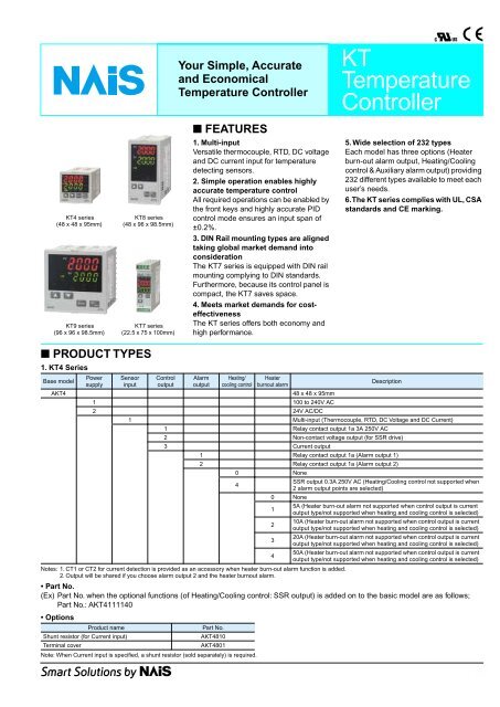
Your Simple, Accurate<br />
and Economical<br />
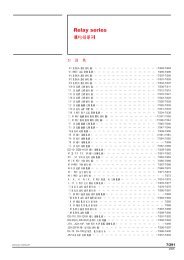
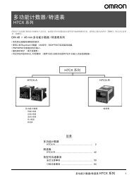
<strong>Temperature</strong> <strong>Controller</strong><br />
<strong>KT</strong><br />
<strong>Temperature</strong><br />
<strong>Controller</strong><br />
■ FEATURES<br />
<strong>KT</strong>4 series<br />
(48 x 48 x 95mm)<br />
<strong>KT</strong>9 series<br />
(96 x 96 x 98.5mm)<br />
<strong>KT</strong>8 series<br />
(48 x 96 x 98.5mm)<br />
<strong>KT</strong>7 series<br />
(22.5 x 75 x 100mm)<br />
1. Multi-input<br />
Versatile thermocouple, RTD, DC voltage<br />
and DC current input for temperature<br />
detecting sensors.<br />
2. Simple operation enables highly<br />
accurate temperature control<br />
All required operations can be enabled by<br />
the front keys and highly accurate PID<br />
control mode ensures an input span of<br />
±0.2%.<br />
3. DIN Rail mounting types are aligned<br />
taking global market demand into<br />
consideration<br />
The <strong>KT</strong>7 series is equipped with DIN rail<br />
mounting complying to DIN standards.<br />
Furthermore, because its control panel is<br />
compact, the <strong>KT</strong>7 saves space.<br />
4. Meets market demands for costeffectiveness<br />
The <strong>KT</strong> series offers both economy and<br />
high performance.<br />
5. Wide selection of 232 types<br />
Each model has three options (Heater<br />
burn-out alarm output, Heating/Cooling<br />
control & Auxiliary alarm output) providing<br />
232 different types available to meet each<br />
user’s needs.<br />
6. The <strong>KT</strong> series complies with UL, CSA<br />
standards and CE marking.<br />
■ PRODUCT TYPES<br />
1. <strong>KT</strong>4 Series<br />
Base model<br />
Power Sensor Control Alarm Heating/ Heater<br />
supply input output output cooling control burnout alarm<br />
Description<br />
A<strong>KT</strong>4<br />
48 x 48 x 95mm<br />
1 100 to 240V AC<br />
2 24V AC/DC<br />
1 Multi-input (Thermocouple, RTD, DC Voltage and DC Current)<br />
1 Relay contact output 1a 3A 250V AC<br />
2 Non-contact voltage output (for SSR drive)<br />
3 Current output<br />
1 Relay contact output 1a (Alarm output 1)<br />
2 Relay contact output 1a (Alarm output 2)<br />
0 None<br />
4<br />
SSR output 0.3A 250V AC (Heating/Cooling control not supported when<br />
2 alarm output points are selected)<br />
0 None<br />
1<br />
5A (Heater burn-out alarm not supported when control output is current<br />
output type/not supported when heating and cooling control is selected)<br />
2<br />
10A (Heater burn-out alarm not supported when control output is current<br />
output type/not supported when heating and cooling control is selected)<br />
3<br />
20A (Heater burn-out alarm not supported when control output is current<br />
output type/not supported when heating and cooling control is selected)<br />
4<br />
50A (Heater burn-out alarm not supported when control output is current<br />
output type/not supported when heating and cooling control is selected)<br />
Notes: 1. CT1 or CT2 for current detection is provided as an accessory when heater burn-out alarm function is added.<br />
2. Output will be shared if you choose alarm output 2 and the heater burnout alarm.<br />
• Part No.<br />
(Ex) Part No. when the optional functions (of Heating/Cooling control: SSR output) is added on to the basic model are as follows;<br />
Part No.: A<strong>KT</strong>4111140<br />
• Options<br />
Product name<br />
Part No.<br />
Shunt resistor (for Current input)<br />
A<strong>KT</strong>4810<br />
Terminal cover<br />
A<strong>KT</strong>4801<br />
Note: When Current input is specified, a shunt resistor (sold separately) is required.<br />
1
<strong>KT</strong>(A<strong>KT</strong>4,7,8,9)<br />
2. <strong>KT</strong>8 Series<br />
Base model<br />
Power Sensor Control Alarm Heating/ Heater<br />
supply input output output cooling control burnout alarm<br />
Description<br />
A<strong>KT</strong>8<br />
48 x 96 x 98.5mm<br />
1 100 to 240V AC<br />
2 24V AC/DC<br />
1 Multi-input (Thermocouple, RTD, DC Voltage and DC Current)<br />
1 Relay contact output 1a1b 3A 250V AC<br />
2 Non-contact voltage output (for SSR drive)<br />
3 Current output<br />
1 Relay contact output 1a (Alarm output 1)<br />
2 Relay contact output 1a (Alarm output 2)<br />
0 None<br />
1 Relay contact output 1a<br />
2 Non-contact voltage output (for SSR drive)<br />
3 Current output<br />
0 None<br />
1<br />
5A (Heater burn-out alarm not supported when control output is current<br />
output type/not supported when heating and cooling control is selected)<br />
2<br />
10A (Heater burn-out alarm not supported when control output is current<br />
output type/not supported when heating and cooling control is selected)<br />
3<br />
20A (Heater burn-out alarm not supported when control output is current<br />
output type/not supported when heating and cooling control is selected)<br />
4<br />
50A (Heater burn-out alarm not supported when control output is current<br />
output type/not supported when heating and cooling control is selected)<br />
Note: CT1 or CT2 for current detection is provided as an accessory when heater burn-out alarm function is added.<br />
• Part No.<br />
(Ex) Part No. when the optional functions (of Alarm output; Alarm output 2 + Heating/Cooling control: Current output) are added on to<br />
the basic model are as follows; Part No.: A<strong>KT</strong>8111230<br />
• Options<br />
Product name<br />
Part No.<br />
Shunt resistor (for Current input)<br />
A<strong>KT</strong>4810<br />
Terminal cover<br />
A<strong>KT</strong>8801<br />
Note: When Current input is specified, a shunt resistor (sold separately) is required.<br />
3. <strong>KT</strong>9 Series<br />
Base model<br />
Power Sensor Control Alarm Heating/ Heater<br />
supply input output output cooling control burnout alarm<br />
Description<br />
A<strong>KT</strong>9<br />
96 x 96 x 98.5mm<br />
1 100 to 240V AC<br />
2 24V AC/DC<br />
1 Multi-input (Thermocouple, RTD, DC Voltage and DC Current)<br />
1 Relay contact output 1a1b 3A 250V AC<br />
2 Non-contact voltage output (for SSR drive)<br />
3 Current output<br />
1 Relay contact output 1a (Alarm output 1)<br />
2 Relay contact output 1a (Alarm output 2)<br />
0 None<br />
1 Relay contact output 1a<br />
2 Non-contact voltage output (for SSR drive)<br />
3 Current output<br />
0 None<br />
1<br />
5A (Heater burn-out alarm not supported when control output is current<br />
output type/not supported when heating and cooling control is selected)<br />
2<br />
10A (Heater burn-out alarm not supported when control output is current<br />
output type/not supported when heating and cooling control is selected)<br />
3<br />
20A (Heater burn-out alarm not supported when control output is current<br />
output type/not supported when heating and cooling control is selected)<br />
4<br />
50A (Heater burn-out alarm not supported when control output is current<br />
output type/not supported when heating and cooling control is selected)<br />
Note: CT1 or CT2 for current detection is provided as an accessory when heater burn-out alarm function is added.<br />
• Part No.<br />
(Ex) Part No. when the optional functions (of Alarm output; Alarm output 2 + Heating/Cooling control: Non-contact voltage output) are<br />
added on to the basic model are as follows; Part No.: A<strong>KT</strong>9111220<br />
• Options<br />
Product name<br />
Part No.<br />
Shunt resistor (for Current input)<br />
A<strong>KT</strong>4810<br />
Terminal cover<br />
A<strong>KT</strong>9801<br />
Note: When Current input is specified, a shunt resistor (sold separately) is required.<br />
2
<strong>KT</strong>(A<strong>KT</strong>4,7,8,9)<br />
4. <strong>KT</strong>7 Series<br />
Base model<br />
Power Sensor Control Alarm Heating/ Heater<br />
supply input output output cooling control burnout alarm<br />
Description<br />
A<strong>KT</strong>7<br />
22.5 x 75 x 100mm<br />
1 100 to 240V AC<br />
2 24V AC/DC<br />
1 Multi-input (Thermocouple, RTD, DC Voltage and DC Current)<br />
1 Relay contact output 1a 3A 250V AC<br />
2 Non-contact voltage output (for SSR drive)<br />
3 Current output<br />
1 Open collector output (Alarm output 1)<br />
0 None (without Heating/Cooling function)<br />
0 None<br />
1 5A (not available for the Current output type) Open collector output<br />
2 10A (not available for the Current output type) Open collector output<br />
3 20A (not available for the Current output type) Open collector output<br />
4 50A (not available for the Current output type) Open collector output<br />
Note: CT1 or CT2 for current detection is provided as an accessory when heater burn-out alarm function is added.<br />
• Part No.<br />
(Ex) Part No. when the optional function (of Heater burnout alarm: 10A) is added on to the base model are as follows;<br />
Part No.: A<strong>KT</strong>7111102<br />
• Options<br />
Product name<br />
Part No.<br />
Shunt resistor (for Current input)<br />
A<strong>KT</strong>4811<br />
Note: When Current input is specified, a shunt resistor (sold separately) is required.<br />
■ PARTS AND FUNCTIONS<br />
• <strong>KT</strong>4 series<br />
• <strong>KT</strong>8 series<br />
1<br />
2<br />
3<br />
4 5<br />
6<br />
1<br />
2<br />
3<br />
1 PV display<br />
Indicates PV (process variable).<br />
2 SV display<br />
Indicates SV (setting value).<br />
3 Increase key<br />
Increases numerical value.<br />
4 Decrease key<br />
Decreases numerical value.<br />
5 Mode key<br />
Switches the setting mode.<br />
6 OUT/OFF key<br />
Control output is turned on or off when<br />
control output is ON.<br />
4 5<br />
6<br />
• <strong>KT</strong>9 series<br />
• <strong>KT</strong>7 series<br />
1<br />
1<br />
2<br />
3 5<br />
2<br />
4<br />
3<br />
4 5<br />
6<br />
Note: Color selection is the same for each size.<br />
3
<strong>KT</strong>(A<strong>KT</strong>4,7,8,9)<br />
■ RATING & SPECIFICATIONS<br />
4<br />
Display<br />
Specifications<br />
<strong>KT</strong>4 <strong>KT</strong>8 <strong>KT</strong>9 <strong>KT</strong>7<br />
Size 48 x 48mm 48 x 96mm 96 x 96mm 22.5 x 75mm<br />
Supply voltage (Must be specified)<br />
Frequency<br />
100 to 240V AC<br />
24V AC/DC<br />
50/60Hz<br />
Power consumption Approx. 8VA Approx. 8VA Approx. 8VA Approx. 6VA<br />
Input type<br />
Input range<br />
K<br />
–200 to 1370°C (–320 to 2500°F)<br />
–199.9 to 400.0°C (–199.9 to 750.0°F)<br />
J<br />
–200 to 1000°C (–320 to 1800°F)<br />
R<br />
0 to 1760°C (0 to 3200°F)<br />
S<br />
0 to 1760°C (0 to 3200°F)<br />
Thermocouple B<br />
0 to 1820°C (0 to 3300°F)<br />
E<br />
–200 to 800°C (–320 to 1500°F)<br />
T<br />
–199.9 to 400.0°C (–199.9 to 750.0°F)<br />
N<br />
–200 to 1300°C (–320 to 2300°F)<br />
PL-II<br />
0 to 1390°C (0 to 2500°F)<br />
C (W/Re5-26)<br />
0 to 2315°C (0 to 4200°F)<br />
RTD<br />
Pt100<br />
–200 to 850°C (–300 to 1500°F)<br />
–199.9 to 850.0°C (–199.9 to 999.9°F)<br />
JPt100<br />
–200 to 500°C (–300 to 900°F)<br />
–199.9 to 500.0°C (–199.9 to 900.0°F)<br />
DC Current<br />
4 to 20mA DC<br />
0 to 20mA DC<br />
0 to 1V DC<br />
–1999 to 9999, –199.9 to 999.9<br />
DC Voltage<br />
0 to 10V DC<br />
–19.99 to 99.99, –1.999 to 9.999<br />
1 to 5V DC<br />
0 to 5V DC<br />
• Scaling and change to the decimal point position is possible for DC current and DC voltage input.<br />
• DC current input is supported with an externally mounted 50Ω shunt resistor (sold separately).<br />
Thermocouple<br />
K, J, R, S, B, E, T, N, PL-II, C (W/Re5-26)<br />
External resistor: Max. 100Ω (max. 40Ω external resistor for B input)<br />
RTD PT100, JPt100 3-conductor system (Allowable input conductor resistance for each conductor: max. 10Ω)<br />
0 to 20 mA DC, 4 to 20 mA DC<br />
Multi-input DC current<br />
Input impedance: 50Ω (Connect 50Ω shunt resistor between input terminals.)<br />
Allowable input current: max. 50 mA (when 50Ω shunt resistor is used)<br />
• 0 to 1V DC<br />
DC voltage<br />
Input impedance: min. 1 MΩ, Allowable input voltage: max 5 V, Allowable signal source resistance: max. 2 kΩ<br />
• 0 to 5 V DC, 1 to 5 V DC, 0 to 10 V DC<br />
Input impedance: min. 100 kΩ, Allowable input voltage: max 15 V, Allowable signal source resistance: max. 100Ω<br />
1a 1a1b 1a1b 1a<br />
Relay contact (Must<br />
3A 250V AC (Resistive load), 1A 250V AC (Inductive load cosφ=0.4), Electric life: 100,000 times<br />
be<br />
Control output Non-contact specified)<br />
+2<br />
12 0 V DC, Max. load current: 40mA (Short-circuit protected)<br />
DC voltage<br />
DC current<br />
4 to 20mADC Load resistance: Max. 550Ω<br />
Alarm output 1<br />
Control mode<br />
Accuracy<br />
Sampling period<br />
Hysteresis<br />
Proportional band<br />
Integral time<br />
Derivative time<br />
Proportional cycle<br />
Allowable voltage fluctuation<br />
Insulated resistance<br />
Breakdown voltage<br />
Malfunction vibration<br />
Relay contact 1a 3A 250VAC (Resistive load)<br />
Electric life: 100,000 times<br />
Open collector, Control<br />
capacity: 24V DC 0.1A (Max.)<br />
Actions mentioned below can be selected by key operation. [Default PID] PID (with auto-tuning function), PI, PD (with manual<br />
reset function), P (with manual reset function), ON/OFF action<br />
Thermocouple: Within ±0.2% of each input span ±1 digit or within ±2°C (4°F) whichever is greater<br />
However, R and S input; Within ±6°C (12°F) in the range of 0 to 200°C (0 to 400°F)<br />
B input 0 to 300°C (0 to 600°F): Accuracy is not guaranteed.<br />
K, J, E, and N input less than 0°C (32°F): Within ±0.4% of input span ±1 digit<br />
RTD: Within ±0.1% of each input span ±1 digit or ±1°C (2°F) whichever is greater<br />
DC current and DC voltage: Within ±0.2% of each input span ±1 digit<br />
250ms<br />
Thermocouple & RTD: 0.1 to 100.0°C (°F)<br />
DC current and DC voltage: 1 to 1000 (The decimal point place follows the selection)<br />
Thermocouple: 0 to 1000°C (0 to 2000°F)<br />
RTD: 0.0 to 999.9°C (0.0 to 999.9°F)<br />
0.0 to 110.0%<br />
DC current and DC voltage: 0.0 to 100.0%<br />
0 to 1000 seconds<br />
0 to 300 seconds<br />
1 to 120 seconds<br />
When 100 to 240V AC; 85 to 264V AC When 24V AC/DC; 20 to 28V AC/DC<br />
500V DC 10MΩ or greater<br />
1.5kV AC for 1min between input terminal and ground terminal,<br />
between input terminal and power terminal<br />
between power terminal and ground terminal<br />
between output terminal and ground terminal, & between output terminal and power terminal<br />
10 to 55Hz (0.35mm) to each direction (120ms sweep) for 10min.<br />
1.5KV AC for 1 min<br />
between input terminal and<br />
power terminal, & between<br />
output terminal and power<br />
terminal
SV1<br />
SV2<br />
OUT1 OUT2 AT TX/RX<br />
OUT1<br />
HB A1 A2/LA<br />
SV1<br />
SV2<br />
MODE<br />
OUT2<br />
OUT<br />
OFF<br />
HB<br />
AT<br />
A1<br />
TX/RX<br />
A2/LA<br />
<strong>KT</strong>(A<strong>KT</strong>4,7,8,9)<br />
Breakdown vibration<br />
10 to 55Hz (0.75mm) to each direction (120ms sweep) for 10min.<br />
Malfunction shock<br />
X, Y & Z each direction for 5 times 10G<br />
Breakdown shock<br />
Same as above, but 30G<br />
Ambient temperature 0 to 50°C<br />
Ambient humidity<br />
35 to 85%RH (No condensation)<br />
Mass Approx. 130g Approx. 240g Approx. 370g Approx. 150g<br />
Waterproof IP66 (applicable only to the front panel subject to rubber gasket employed) None<br />
Display character height<br />
Options<br />
Display<br />
PV: 10.2mm<br />
SV: 8.8mm<br />
PV: 11.2mm<br />
SV: 11.2mm<br />
PV: 18mm<br />
SV: 13.2mm<br />
PV: 7.4mm<br />
SV: 7.4mm<br />
Alarm output 2 The same as the one of Alarm output 1 None<br />
• Relay contact: 1a 250V AC 3A (Resistive load),<br />
250V AC 1A (Inductive load cosø=0.4),<br />
Heating/Cooling<br />
Non contact relay<br />
Electric life: 100,000 times<br />
control<br />
0.3A 250V AC (Resistive load)<br />
+2<br />
• Non-contact voltage: 12 0 V DC Max. 40mA<br />
None<br />
(Short-circuit protected)<br />
• DC current: 4 to 20mA DC Load resistance: Max. 550Ω<br />
Heater burn-out alarm<br />
output<br />
Specifications<br />
<strong>KT</strong>4 <strong>KT</strong>8 <strong>KT</strong>9 <strong>KT</strong>7<br />
Heater rated current must be selected from 5A, 10A, 20A and 50A.<br />
Setting accuracy: Within 5% of heater rated current<br />
Relay contact 1a 250V AC 3A (Resistive load), Electric life: 100,000 times<br />
Open collector, Control<br />
capacity: 24V DC 0.1A (Max.)<br />
■ DIMENSION DIAGRAM (unit: mm inch) Tolerance: ±<br />
1. <strong>KT</strong>4 series<br />
• External dimension<br />
• Panel cutout<br />
Rubber gasket<br />
Screw type mounting<br />
75<br />
2.953<br />
PV<br />
OUT1<br />
OUT2<br />
SV<br />
A1<br />
EVT<br />
SV1 SV2 TX/RX AT<br />
OUT<br />
MODE<br />
OFF<br />
<strong>KT</strong>4<br />
44.5<br />
1.752<br />
59.7<br />
2.350<br />
75<br />
2.953<br />
45<br />
1.772<br />
+0.5<br />
45−0<br />
1.772<br />
+0.5<br />
−0<br />
+.020<br />
−0<br />
+.020<br />
−0<br />
+0.5<br />
n × 48 – 3<br />
n × 1.890 – .118<br />
−0 +.020<br />
−0<br />
Lateral close mounting<br />
n: Number of units mounted<br />
45<br />
1.772<br />
+0.5<br />
−0<br />
+.020<br />
−0<br />
M48<br />
M1.890<br />
11.5<br />
.453<br />
95<br />
3.740<br />
2. <strong>KT</strong>8 series<br />
• External dimension<br />
Rubber gasket<br />
Screw type mounting<br />
• Panel cutout<br />
75<br />
2.953<br />
PV<br />
92<br />
3.622<br />
+0.5<br />
−0<br />
+.020<br />
−0<br />
SV<br />
96<br />
3.780<br />
91<br />
3.583<br />
106.2<br />
4.181<br />
130<br />
5.118<br />
92<br />
3.622<br />
+0.5<br />
−0<br />
+.020<br />
−0<br />
+0.5<br />
n × 48 – 3<br />
n × 1.890 – .118<br />
−0 +.020<br />
−0<br />
Lateral close mounting<br />
n: Number of units mounted<br />
<strong>KT</strong>8<br />
+0.5<br />
45−0<br />
1.772<br />
+.020<br />
−0<br />
48<br />
1.890<br />
11.5<br />
.453<br />
98.5<br />
3.878<br />
3. <strong>KT</strong>9 series<br />
• External dimension<br />
Rubber gasket<br />
Screw type mounting<br />
• Panel cutout<br />
130<br />
5.118<br />
PV<br />
92<br />
3.622<br />
+0.8<br />
−0<br />
+.031<br />
−0<br />
SV<br />
91<br />
3.583<br />
106.2<br />
4.181<br />
130<br />
5.118<br />
+0.5<br />
n × 96 – 3<br />
n × 3.780 – .118<br />
−0 +.020<br />
−0<br />
Lateral close mounting<br />
n: Number of units mounted<br />
MODE<br />
OUT<br />
OFF<br />
<strong>KT</strong>9<br />
+0.5<br />
M92 −0<br />
M3.622<br />
+.020<br />
−0<br />
M96<br />
M3.780<br />
11.5<br />
.453<br />
98.5<br />
3.878<br />
5
G/T<br />
<strong>KT</strong>(A<strong>KT</strong>4,7,8,9)<br />
4. <strong>KT</strong>7 series<br />
• External dimension<br />
1 2 3 4<br />
<strong>KT</strong>7<br />
OUT<br />
EVT<br />
T/R<br />
AT<br />
PV<br />
SV<br />
75<br />
2.953<br />
MODE<br />
5<br />
6<br />
7<br />
8<br />
9<br />
22.5<br />
.886<br />
97<br />
3.819<br />
100<br />
3.937<br />
• Panel Mounting<br />
Mountable panel thickness: Within 1 to 15mm .039 to .591inch<br />
Insert a controller from the front side of the panel.<br />
Attach the mounting brackets by the holes at the top and bottom<br />
of the case and secure the controller in place with the screws.<br />
• DIN rail mounting (<strong>KT</strong>7)<br />
1) Hook 1 of the <strong>KT</strong>7 on the upper side of the DIN rail.<br />
2) Making the 1 part of the <strong>KT</strong>7 as a support, fit the lower part of<br />
the <strong>KT</strong>7 to the DIN rail.<br />
<strong>KT</strong>7 will be completely fixed to the DIN rail with a “Click” sound.<br />
Recommended DIN rail: Part No. ATA48011<br />
Recommended fastening plate: Part No. ATA4806<br />
1<br />
DIN rail<br />
pv<br />
av<br />
G/T EVT T/B AT<br />
MODE<br />
pv<br />
av<br />
<strong>KT</strong>7<br />
EVT T/B AT<br />
Fastening plate<br />
Notice<br />
As the case is made of resin, do not<br />
use excessive force while screwing<br />
in the mounting bracket. The torque<br />
is approximately 0.12N·m<br />
MODE<br />
5 6 7 8 9<br />
2<br />
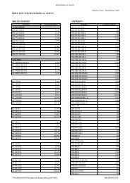
■ OPTION<br />
1. Shunt resistor 2. Terminal cover<br />
A<strong>KT</strong>4810 (for <strong>KT</strong>4,8 and 9)<br />
A<strong>KT</strong>4811 (for <strong>KT</strong>7)<br />
A<strong>KT</strong>4801 (for <strong>KT</strong>4) A<strong>KT</strong>8801 (for <strong>KT</strong>8)<br />
A<strong>KT</strong>9801 (for <strong>KT</strong>9)<br />
26 ±1<br />
9<br />
1.024 ±.039 9 × × 8.4 .331 = = 75.6<br />
2.976<br />
9 9 × × 8.4 .331 = = 75.6<br />
2.976 19 20<br />
.748 .787<br />
40<br />
1.575<br />
44.5<br />
74 ±6<br />
1.752<br />
2.913 ±.236<br />
47.7<br />
1.878<br />
48<br />
1.890<br />
6<br />
.236<br />
88<br />
3.465<br />
92<br />
3.622<br />
29<br />
1.142<br />
20<br />
.787<br />
22.3<br />
.878<br />
24.5<br />
.965<br />
6<br />
.236<br />
Note: 2pcs of terminal cover of A<strong>KT</strong>8801<br />
can be used as an A<strong>KT</strong>9801 cover.<br />
6
3. Current transformer (CT)<br />
• External dimension<br />
1) CT1 (for 5,10 and 20A) A<strong>KT</strong>4815<br />
2) CT2 (for 50A) A<strong>KT</strong>4816<br />
<strong>KT</strong>(A<strong>KT</strong>4,7,8,9)<br />
5.8 dia.<br />
.228 dia.<br />
l<br />
15<br />
.591<br />
k<br />
0.5<br />
.020<br />
7.5<br />
.295<br />
2.8<br />
.110<br />
l 30<br />
1.181<br />
k<br />
10.5<br />
.413<br />
25<br />
.984<br />
K<br />
L<br />
100<br />
3.937<br />
21<br />
.827<br />
40<br />
1.575<br />
3<br />
.118<br />
10<br />
.394<br />
40<br />
1.575<br />
30<br />
1.181<br />
2-3.5 dia.<br />
2-.138 dia.<br />
40<br />
1.575<br />
30<br />
1.181<br />
12 dia.<br />
.472 dia.<br />
2-M3 .118<br />
15<br />
.591<br />
Note: CT1 or CT2 for current detection is provided as an accessory when heater<br />
burn-out alarm function is added.<br />
■ EXTERNAL CONNECTION DIAGRAM<br />
1. <strong>KT</strong>4 series<br />
POWER<br />
POWER<br />
OUT1<br />
SUPPLY<br />
SUPPLY<br />
1 1 11 6<br />
100 to<br />
RELAY<br />
24V AC/DC<br />
CT NO<br />
240V AC<br />
V/A<br />
2 2 12 7<br />
3A<br />
3A<br />
250V<br />
250V AC<br />
OUT2<br />
AC<br />
A<br />
3 8<br />
S<br />
EVT<br />
0.3A<br />
250V<br />
AC<br />
A1<br />
4<br />
5<br />
• POWER SUPPLY: Power supply<br />
• OUT1: Control output 1<br />
• OUT2: Control output 2 for heating and<br />
cooling<br />
• RELAY: Relay contact output<br />
• V/A: DC voltage/DC current output<br />
• V: Non-contact voltage output<br />
• A1: Alarm output 1<br />
• EVT: Event output (Alarm output 2 or Heater<br />
burn-out alarm)<br />
• CT: CT input<br />
• TC: Thermocouple<br />
• RTD: Resistance temperature detector<br />
• DC: DC current or DC voltage<br />
NO<br />
NO<br />
<strong>KT</strong>4<br />
9<br />
B<br />
10<br />
B<br />
TC RTD DC<br />
2. <strong>KT</strong>8 and <strong>KT</strong>9 series • POWER SUPPLY: Power supply<br />
• OUT1: Control output 1<br />
POWER<br />
SUPPLY<br />
2<br />
GND<br />
POWER<br />
SUPPLY<br />
24V AC/DC 100 to 240V AC<br />
3<br />
3<br />
1<br />
2<br />
4<br />
OUT1 NC<br />
5<br />
RELAY<br />
NO<br />
V/A<br />
6 3A<br />
250V AC<br />
7<br />
11<br />
12<br />
NO A2/(HB)<br />
13<br />
3A<br />
250V AC<br />
14<br />
15<br />
16<br />
17<br />
CT<br />
SV2<br />
A1 NO<br />
A<br />
8 3A<br />
18<br />
OUT2/HB 250V AC<br />
9<br />
19<br />
RELAY<br />
B<br />
NO<br />
TC DC<br />
V/A<br />
B<br />
10 3A<br />
20<br />
RTD<br />
250V AC <strong>KT</strong>8/<strong>KT</strong>9<br />
• OUT2: Control output 2 for heating and<br />
cooling<br />
• RELAY: Relay contact output<br />
• V/A: DC voltage/DC current output<br />
• A1: Alarm output 1<br />
• A2: Alarm output 2<br />
• HB: Heater burn-out alarm output<br />
• SV2: Secondary main setting<br />
• CT: CT input<br />
• TC: Thermocouple<br />
• RTD: Resistance temperature detector<br />
• DC: DC current or DC voltage<br />
3. <strong>KT</strong>7 series<br />
POWER SUPPLY<br />
24V AC/DC<br />
POWER SUPPLY<br />
100 to 240V AC<br />
TC<br />
1<br />
<strong>KT</strong>7<br />
2<br />
3A<br />
250V AC<br />
0.1A<br />
24V DC<br />
5 6 7 8 9<br />
RTD A B B<br />
OUT<br />
V/A<br />
RELAY<br />
1 2 3 4<br />
EVT<br />
• POWER SUPPLY: Power supply<br />
• OUT: Control output<br />
• RELAY: Relay contact output<br />
• V/A: DC voltage/DC current output<br />
• EVT: Event output [outputs when alarm, loop<br />
break alarm or heater burn-out alarm<br />
(option) is ON]<br />
• TC: Thermocouple<br />
• RTD: Resistance temperature detector<br />
• DC: DC current or DC voltage<br />
DC<br />
CT<br />
7
<strong>KT</strong>(A<strong>KT</strong>4,7,8,9)<br />
■ NOTICE ON OPERATION<br />
1. NOTICE ON SITE SELECTION<br />
This instrument is intended to be used in<br />
the following environment (IEC61010-1)<br />
Overvoltage category II, Pollution degree<br />
2<br />
Mount the controller in a place with:<br />
1) A minimum of dust, and an absence of<br />
corrosive gases<br />
2) No flammable, explosive gases<br />
3) Few mechanical vibrations or shocks<br />
4) No exposure to direct sunlight, an<br />
ambient temperature of 0 to 50°C (32 to<br />
122°F) that does not change rapidly<br />
5) An ambient non-condensing humidity<br />
of 35 to 85%RH<br />
6) No large capacity electromagnetic<br />
switches or cables through which large<br />
current is flowing<br />
7) No water, oil or chemicals or where the<br />
vapors of these substances can come into<br />
direct contact with the controller<br />
2. NOTICE ON THE WIRING<br />
1) The terminal block of <strong>KT</strong>4, 8 and 9<br />
series are designed to be wired from the<br />
left side. The lead wire must be inserted<br />
from the left side of the terminal, and<br />
fastened by the terminal screw. Use a<br />
solderless terminal with insulation sleeve<br />
that fits to the M3 screw.<br />
Max. 5.8mm<br />
.228inch<br />
3.2mm dia.<br />
.126inch dia.<br />
Max. 5.8mm<br />
.228inch<br />
3.2mm<br />
.126inch<br />
2) Terminal fastening torque is approximately<br />
0.6N·m to 1.0N·m (<strong>KT</strong>4, 8 & 9).<br />
For <strong>KT</strong>7 series by M2.6 screw is less than<br />
0.5N·m and by M2.0 screw 0.25N·m<br />
respectively.<br />
3) Use a thermocouple and compensating<br />
lead wire according to the input<br />
specification of the controller.<br />
4) Use a 3-wire system of RTD according<br />
to the input specification of the controller.<br />
5) This controller has no built-in power<br />
switch, circuit breaker or fuse. Therefore,<br />
it is necessary to install them in the circuit<br />
near the external controller.<br />
(Recommended fuse: Time-lag fuse,<br />
rated voltage 250V AC, rated current 2A)<br />
6) In the case of 24V AC/DC power<br />
supply, do not confuse the polarity when it<br />
is DC.<br />
7) With the relay contact output type, use<br />
an auxiliary electromagnetic switch<br />
externally according to the capacity of the<br />
load to protect the built-in relay contact.<br />
8) When wiring, keep input wire<br />
(thermocouple, RTD, etc.) away from AC<br />
source and load wire to avoid external<br />
interference.<br />
9) Turn the power supply to the instrument<br />
off before wiring or checking. Working or<br />
touching the terminal with the power<br />
switched on may result in Electric Shock<br />
which could cause severe injury or death.<br />
10) Do not drop wire chips into the holes<br />
of vent when wiring, because they could<br />
cause fire, malfunction or trouble with the<br />
device.<br />
11) To prevent the unit from harmful<br />
effects of unexpected high level noise, it is<br />
recommended that a surge absorber be<br />
installed between the electromagnetic<br />
switch coils.<br />
3. NOTICE ON THE MOUNTING<br />
1) Do not use excessive force while<br />
screwing in the mounting bracket of <strong>KT</strong>4,<br />
8 & 9 series. Recommended torque is<br />
approximately 0.12N·m.<br />
2) When mounting the <strong>KT</strong>7 series to the<br />
DIN rail, mount it in a lateral direction.<br />
Make sure a click is audible when fixed<br />
into place.<br />
4. OPTIONAL HEATER BURN-OUT<br />
ALARM OUTPUT<br />
1) This alarm is not available for detecting<br />
current under phase control.<br />
2) Use the current transformer (CT)<br />
provided, and pass one lead wire of the<br />
heater circuit into the hole of CT.<br />
3) When wiring, keep CT wire away from<br />
AC source and load wire to avoid external<br />
interference.<br />
CT<br />
Heater<br />
CT input terminal<br />
Power supply<br />
These materials are printed on ECF pulp.<br />
These materials are printed with earth-friendly vegetable-based (soybean oil) ink.<br />
Please contact ..........<br />
Matsushita Electric Works, Ltd.<br />
Automation Controls Company<br />
Head Office: 1048, Kadoma, Kadoma-shi, Osaka 571-8686, Japan<br />
Telephone: Japan (81) Osaka (06) 6908-1050<br />
Facsimile: Japan (81) Osaka (06) 6908-5781<br />
http://www.nais-e.com/<br />
8ARCT1B195E-1 200207-8YT<br />
Specifications are subject to change without notice.<br />
COPYRIGHT © 2002 All Rights Reserved<br />
Printed in Japan.