guidelines for delineation of well head protection areas in new jersey
guidelines for delineation of well head protection areas in new jersey
guidelines for delineation of well head protection areas in new jersey

You also want an ePaper? Increase the reach of your titles
YUMPU automatically turns print PDFs into web optimized ePapers that Google loves.
NEW JERSEY GEOLOGICAL SURVEY<br />
OPEN-FILE REPORT OFR 03-1<br />
GUIDELINES FOR DELINEATION<br />
OF WELL HEAD PROTECTION AREAS<br />
IN NEW JERSEY<br />
New Jersey Department <strong>of</strong> Environmental Protection
STATE OF NEW JERSEY<br />
James E. McGreevey, Governor<br />
Department <strong>of</strong> Environmental Protection<br />
Bradley M. Campbell, Commissioner<br />
Land Use Management<br />
Ernest P. Hahn, Assistant Commissioner<br />
Geological Survey<br />
Karl Muessig, State Geologist<br />
NEW JERSEY DEPARTMENT OF ENVIRONMENTAL PROTECTION<br />
The Department <strong>of</strong> Environmental Protection’s mission is to assist the residents <strong>of</strong> New Jersey<br />
<strong>in</strong> preserv<strong>in</strong>g, susta<strong>in</strong><strong>in</strong>g, protect<strong>in</strong>g and enhanc<strong>in</strong>g the environment to ensure the <strong>in</strong>tegration <strong>of</strong><br />
high environmental quality, public health, and economic vitality.<br />
NEW JERSEY GEOLOGICAL SURVEY<br />
The mission <strong>of</strong> the New Jersey Geological Survey is to map, research, <strong>in</strong>terpret and provide<br />
scientific <strong>in</strong><strong>for</strong>mation regard<strong>in</strong>g the State’s geology and ground-water resources. This <strong>in</strong><strong>for</strong>mation<br />
supports the regulatory and plann<strong>in</strong>g functions <strong>of</strong> the Department and other governmental<br />
agencies and provides the bus<strong>in</strong>ess community and public with the <strong>in</strong><strong>for</strong>mation<br />
necessary to address environmental concerns and make economic decisions.<br />
For more <strong>in</strong><strong>for</strong>mation contact:<br />
New Jersey Department <strong>of</strong> Environmental Protection<br />
New Jersey Geological Survey Water Supply Adm<strong>in</strong>istration<br />
P.O. Box 427<br />
Bureau <strong>of</strong> Safe Dr<strong>in</strong>k<strong>in</strong>g Water<br />
Trenton, NJ 08625-0427 P.O. Box 426<br />
(609) 984-6587 Trenton, NJ 08625-0426<br />
http://www.state.nj.us/dep/njgs/ (609) 292-5550<br />
http://www.state.nj.us/dep/watersupply<br />
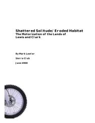
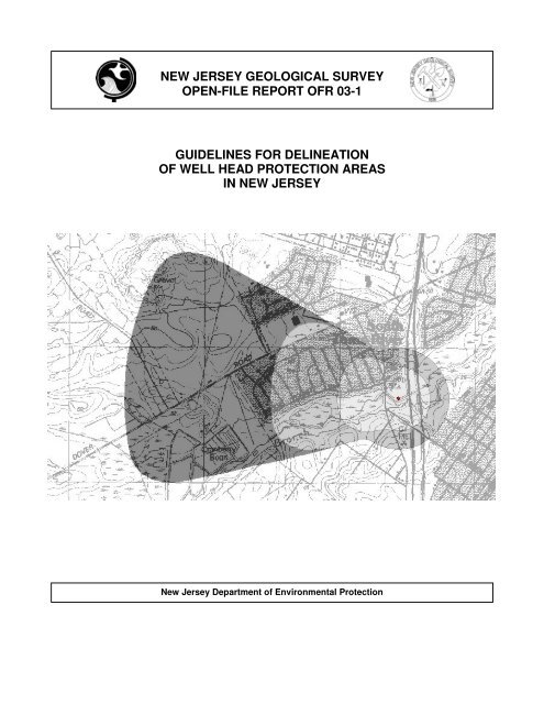
Cover illustration: An example <strong>of</strong> a WHPA is shown. The Well Head Protection Area is broken <strong>in</strong>to three tiers; Tier<br />
1, or the 2-year time <strong>of</strong> travel (TOT), is shown <strong>in</strong> light gray, Tier 2, or 5-year TOT, is shown <strong>in</strong> middle gray, and Tier<br />
3, or the 12-year TOT, is shown <strong>in</strong> dark gray. Ground water movement is from left to right across the picture toward<br />
the pump<strong>in</strong>g <strong>well</strong> near center <strong>of</strong> Tier 1.
New Jersey Geological Survey<br />
Guidel<strong>in</strong>es <strong>for</strong> Del<strong>in</strong>eation <strong>of</strong><br />
Well Head Protection Areas<br />
<strong>in</strong> New Jersey<br />
Compiled by<br />
Steven E. Spayd and Stephen W. Johnson<br />
New Jersey Department <strong>of</strong> Environmental Protection<br />
New Jersey Geological Survey<br />
P.O. Box 427<br />
Trenton, New Jersey 08625-0427<br />
2003<br />
Pr<strong>in</strong>ted on recycled paper
CONVERSION FACTORS<br />
multiply by to obta<strong>in</strong><br />
<strong>in</strong>ch 25.4 millimeter<br />
foot 0.3048 meter<br />
mile 1.609 kilometer<br />
gallons per m<strong>in</strong>ute 0.06308 liters per second<br />
gallons per m<strong>in</strong>ute 192.5 cubic feet per day<br />
gallons per day 0.000694 gallons per m<strong>in</strong>ute<br />
foot per day 0.3048 meters per day<br />
"The water that occurs below the surface <strong>of</strong> the land is <strong>in</strong>visible and relatively <strong>in</strong>accessible and has consequently always<br />
possessed an aspect <strong>of</strong> mystery. What is the mode <strong>of</strong> its occurrence; what is its quantity; whither does it come; is it stationary<br />
or <strong>in</strong> motion? If <strong>in</strong> motion, what is its dest<strong>in</strong>ation and its rate <strong>of</strong> movement, and what are the <strong>for</strong>ces that propel<br />
it through the earth…? These are some <strong>of</strong> the questions that confront the hydrologists who endeavor to look below the<br />
surface. They are questions <strong>of</strong> almost <strong>in</strong>f<strong>in</strong>ite complexity, <strong>in</strong>volv<strong>in</strong>g a great amount <strong>of</strong> physics and chemistry and almost<br />
the whole field <strong>of</strong> geology."<br />
From Physics <strong>of</strong> the Earth-IX-Hydrology, page 385, Oscar E. Me<strong>in</strong>zer, U.S. Geological Survey, 1942.<br />
Additional copies <strong>of</strong> this and other reports may be obta<strong>in</strong>ed from:<br />
DEP Maps and Publications Sales Office<br />
P.O. Box 438<br />
Trenton, NJ 08625-0438<br />
(609) 777-1038<br />
A price list is available on request and on the Internet at http://www.state.nj.us/dep/njgs/.<br />
Use <strong>of</strong> brand, commercial, or trade names is <strong>for</strong> identification purposes only and does not constitute endorsement by the New Jersey Geological Survey.
CONTENTS<br />
Introduction 1<br />
BACKGROUND ............................................................................................................................................................1<br />
PURPOSE AND SCOPE..................................................................................................................................................2<br />
DELINEATION IMPACTS ..............................................................................................................................................2<br />
PUBLIC COMMENT......................................................................................................................................................3<br />
ACKNOWLEDGEMENTS ...............................................................................................................................................3<br />
General Del<strong>in</strong>eation Requirements 3<br />
DELINEATION TIERS ...................................................................................................................................................3<br />
DELINEATION METHODS ............................................................................................................................................4<br />
Approved Del<strong>in</strong>eation Methods 5<br />
DELINEATION METHOD SELECTION............................................................................................................................5<br />
CFR MATRIX METHOD ..............................................................................................................................................5<br />
CFR CALCULATION METHOD......................................................................................................................................6<br />
COMBINED MODEL/CFR METHOD.............................................................................................................................9<br />
NON-CFR MODEL METHOD.....................................................................................................................................10<br />
THREE-DIMENSIONAL MODEL METHOD.....................................................................................................................11<br />
ADVANCED DELINEATIONS AND WHPA REVISIONS ................................................................................................12<br />
Data Selection and Parameter Estimation 12<br />
HYDRAULIC GRADIENT ............................................................................................................................................13<br />
TRANSMISSIVITY ......................................................................................................................................................15<br />
EFFECTIVE POROSITY ...............................................................................................................................................15<br />
AQUIFER THICKNESS ................................................................................................................................................19<br />
PUMPING RATE.........................................................................................................................................................20<br />
WELL RADIUS ..........................................................................................................................................................21<br />
ANISOTROPY ............................................................................................................................................................21<br />
Submission <strong>of</strong> Del<strong>in</strong>eations 21<br />
Del<strong>in</strong>eation Mapp<strong>in</strong>g Requirements 22<br />
References 24<br />
Recommended Resources 24<br />
GLOSSARY 26<br />
FIGURES<br />
Figure 1 : Long axis <strong>of</strong> zone <strong>of</strong> contribution is aligned <strong>in</strong> the direction <strong>of</strong> the regional<br />
ground-water flow direction ..................................................................................................................................9<br />
Figure 2. Clockwise and counter-clockwise 20 degree angle <strong>of</strong> rotation applied to calculated<br />
zone <strong>of</strong> contribution us<strong>in</strong>g the <strong>well</strong> as the pivot po<strong>in</strong>t. ........................................................................................10<br />
Figure 3. CFR portion <strong>of</strong> WHPA superimposed on the results <strong>of</strong> the ground-water model<br />
portion <strong>of</strong> the WHPA...........................................................................................................................................10<br />
Figure 4. Result<strong>in</strong>g outer boundary <strong>of</strong> the comb<strong>in</strong>ed CFR and model portions established <strong>for</strong><br />
each tier <strong>of</strong> the WHPA <strong>del<strong>in</strong>eation</strong>. .....................................................................................................................10<br />
Figure 5. Non-CFR model method zone <strong>of</strong> contribution example...............................................................................11<br />
Figure 6. Clockwise and counter-clockwise 20-degree angle <strong>of</strong> rotation applied to non-CFR<br />
model method <strong>of</strong> contribution us<strong>in</strong>g the <strong>well</strong> as the pivot po<strong>in</strong>t..........................................................................11<br />
Figure 7. Outer boundaries <strong>of</strong> the rotated tiers are established as the WHPA <strong>del<strong>in</strong>eation</strong>. .........................................11
TABLES<br />
Table 1a. Calculated fixed radius <strong>in</strong> feet. Unconsolidated Glacial and Coastal Pla<strong>in</strong> aquifers<br />
consist<strong>in</strong>g <strong>of</strong> sand and gravel; effective porosity = 25%. ......................................................................................7<br />
Table 1b. Calculated fixed radius matrix <strong>in</strong> feet <strong>for</strong> bedrock aquifers consist<strong>in</strong>g <strong>of</strong> sandstone,<br />
conglomerate, shale, limestone, dolomite, granite, gniess, diabase, and other sedimentary,<br />
igneous and metamorphic rocks; effective porosity = 2%. ....................................................................................8<br />
Table 2. Selection <strong>of</strong> <strong>in</strong>put values <strong>for</strong> WHPA <strong>del<strong>in</strong>eation</strong>...........................................................................................14<br />
Table 3. Summary <strong>of</strong> horizontal conductivity (k) values <strong>for</strong> geologic and hydrogeologic<br />
units <strong>in</strong> New Jersey as <strong>of</strong> January 2002. ..............................................................................................................17<br />
Table 4. Summary <strong>of</strong> transmissivity values <strong>for</strong> geologic and hydrogeologic units <strong>in</strong><br />
New Jersey as <strong>of</strong> January 2002............................................................................................................................18<br />
Table 5. Average depth <strong>of</strong> unconf<strong>in</strong>ed, public-supply <strong>well</strong>s <strong>in</strong> selected aquifers........................................................20
GUIDELINES FOR DELINEATION OF<br />
WELL HEAD PROTECTION AREAS<br />
IN NEW JERSEY<br />
Introduction<br />
Background<br />
The 1986 Federal Safe Dr<strong>in</strong>k<strong>in</strong>g Water Act<br />
Amendments (Section 1428, P.L. 93-523, 42 USC<br />
300 et. seq.) direct all States to develop a Well Head<br />
Protection Program (WHPP) Plan <strong>for</strong> both public<br />
community (CWS) and public non-community<br />
(NCWS) water-supply <strong>well</strong>s. New Jersey’s WHPP<br />
Plan was approved by the U.S. Environmental Protection<br />
Agency (EPA) <strong>in</strong> December 1991. A goal <strong>of</strong><br />
the WHPP Plan is to prevent contam<strong>in</strong>ation <strong>of</strong><br />
ground-water resources, which provide dr<strong>in</strong>k<strong>in</strong>g water<br />
to roughly <strong>for</strong>ty-two percent <strong>of</strong> New Jersey’s<br />
population. The <strong>del<strong>in</strong>eation</strong> <strong>of</strong> Well Head Protection<br />
Areas (WHPA's) is one component <strong>of</strong> the WHPP.<br />
The WHPA is the area from which a <strong>well</strong> draws its<br />
water with<strong>in</strong> a specified time frame. Once del<strong>in</strong>eated,<br />
these <strong>areas</strong> become a priority <strong>for</strong> ef<strong>for</strong>ts to prevent<br />
and clean up ground-water contam<strong>in</strong>ation.<br />
Other components <strong>of</strong> the WHPP Plan <strong>in</strong>clude pollution-source<br />
<strong>in</strong>ventories, development and implementation<br />
<strong>of</strong> best management practices to protect ground<br />
water, land-use plann<strong>in</strong>g, and education to promote<br />
public awareness <strong>of</strong> each person’s role <strong>in</strong> protect<strong>in</strong>g<br />
our ground-water resources.<br />
The Safe Dr<strong>in</strong>k<strong>in</strong>g Water Act Amendments <strong>of</strong><br />
1996 (P.L. 104-182) established the need <strong>for</strong> each<br />
State to have a Source Water Assessment Program<br />
(SWAP). In New Jersey, source-water assessment<br />
<strong>areas</strong> <strong>for</strong> all public supply <strong>well</strong>s will be established<br />
by NJDEP us<strong>in</strong>g these WHPA <strong>del<strong>in</strong>eation</strong> methods.<br />
Public supply <strong>well</strong>s draw water from underground<br />
water sources known as aquifers. Aquifers<br />
are geologic units that are porous and permeable<br />
enough to hold and allow water to flow through them<br />
<strong>in</strong> quantities sufficient to supply <strong>well</strong>s. The water<br />
conta<strong>in</strong>ed <strong>in</strong> these aquifers is called ground water.<br />
Ground water moves from po<strong>in</strong>ts <strong>of</strong> high pressure<br />
(<strong>of</strong>ten high elevation) to po<strong>in</strong>ts <strong>of</strong> lower pressure<br />
such as streams, spr<strong>in</strong>gs, and pump<strong>in</strong>g <strong>well</strong>s. When a<br />
<strong>well</strong> is pump<strong>in</strong>g, nearby ground water flows toward<br />
it. The longer the <strong>well</strong> pumps, the greater is the distance<br />
from which water will flow through the aquifer<br />
to the pump<strong>in</strong>g <strong>well</strong>. For example, pump<strong>in</strong>g a typical<br />
community supply <strong>well</strong> <strong>in</strong> New Jersey’s coastal pla<strong>in</strong><br />
<strong>for</strong> two years may draw ground water from 1,500 feet<br />
away. If the <strong>well</strong> cont<strong>in</strong>ues to pump <strong>for</strong> twelve years,<br />
ground water may be drawn from about a mile upgradient<br />
<strong>of</strong> the <strong>well</strong>. The time it takes a given particle<br />
<strong>of</strong> ground water to flow to a pump<strong>in</strong>g <strong>well</strong> is<br />
known as the time <strong>of</strong> travel (TOT). The TOT is directly<br />
related to the distance the water has to travel to<br />
arrive at the <strong>well</strong> once it starts pump<strong>in</strong>g. However,<br />
<strong>for</strong> any given TOT, the distance will vary from <strong>well</strong><br />
to <strong>well</strong> depend<strong>in</strong>g on the rate <strong>of</strong> pump<strong>in</strong>g and aquifer<br />
characteristics such as the transmissivity, porosity,<br />
hydraulic gradient, and aquifer thickness. Each<br />
WHPA is divided <strong>in</strong>to three sequential tiers based on<br />
the TOT component. The tiers are used to assess the<br />
relative risk <strong>of</strong> contam<strong>in</strong>ation to the <strong>well</strong> by plac<strong>in</strong>g a<br />
higher priority on pollution sources, prevention and<br />
remedies <strong>in</strong> the tiers closest to the <strong>well</strong>s.<br />
Aquifers are recharged with water from precipitation<br />
that percolates through pervious land surfaces<br />
and becomes part <strong>of</strong> the flow <strong>of</strong> ground water.<br />
It is with<strong>in</strong> the WHPA that land uses which <strong>in</strong>troduce<br />
pollutants, are most likely to contam<strong>in</strong>ate dr<strong>in</strong>k<strong>in</strong>g<br />
water sources. Historically, land uses and commercial<br />
and <strong>in</strong>dustrial facilities and activities have been<br />
identified as major sources <strong>of</strong> ground-water contam<strong>in</strong>ation<br />
<strong>in</strong> New Jersey (NJ Water Quality Inventory<br />
Report, 1992). These <strong>in</strong>clude, but are not limited to:<br />
underground storage tanks, septic systems, surface<br />
spills, unsecured landfills, leak<strong>in</strong>g drums, above<br />
ground storage tanks, road salt piles, and lagoons/surface<br />
impoundments.<br />
Once WHPA's are del<strong>in</strong>eated, potential pollution<br />
sources may be managed <strong>in</strong> relation to their location<br />
with<strong>in</strong> the WHPA. In addition, protective land<br />
uses, such as preserved open space, may be established.<br />
In <strong>in</strong>stances where a public supply <strong>well</strong> has<br />
already been contam<strong>in</strong>ated, the WHPA provides <strong>in</strong>vestigators<br />
with an area <strong>in</strong> which to search <strong>for</strong> potential<br />
pollution sources and responsible parties.<br />
1
Under SWAP, the Department has del<strong>in</strong>eated<br />
WHPA’ s <strong>for</strong> the approximately 2,425 community<br />
water supply <strong>well</strong>s (CWS <strong>well</strong>s), and will be establish<strong>in</strong>g<br />
WHPA’ s <strong>for</strong> the roughly 5,000 noncommunity<br />
water water supply <strong>well</strong>s (NCWS <strong>well</strong>s)<br />
<strong>in</strong> the near future.<br />
Purpose and Scope<br />
It is the purpose <strong>of</strong> these <strong>guidel<strong>in</strong>es</strong> to establish<br />
the approved methods <strong>for</strong> <strong>del<strong>in</strong>eation</strong> and submission<br />
<strong>of</strong> WHPA's <strong>in</strong> New Jersey. In accordance with<br />
SWAP, the Department will del<strong>in</strong>eate WHPA's <strong>for</strong> all<br />
exist<strong>in</strong>g and <strong>new</strong> CWS and NCWS <strong>well</strong>s. Based upon<br />
their own needs, concerns or requirements <strong>for</strong> both<br />
CWS and NCWS <strong>well</strong>s, <strong>in</strong>terested parties may per<strong>for</strong>m<br />
WHPA <strong>del<strong>in</strong>eation</strong>s at an advanced level as<br />
def<strong>in</strong>ed later <strong>in</strong> this guidance.<br />
These <strong>guidel<strong>in</strong>es</strong> will be used by the Department<br />
as <strong>well</strong> as by outside parties <strong>in</strong>terested <strong>in</strong> per<strong>for</strong>m<strong>in</strong>g<br />
<strong>del<strong>in</strong>eation</strong>s. A WHPA <strong>del<strong>in</strong>eation</strong> may be<br />
required as the result <strong>of</strong> Department regulations, or<br />
through a Department-approved remedial <strong>in</strong>vestigation<br />
or remedial-action work plans. Until such time<br />
that regulatory standards <strong>for</strong> WHPA <strong>del<strong>in</strong>eation</strong>s are<br />
established, it is the Department's <strong>in</strong>tent that all public<br />
entities require WHPA's to be del<strong>in</strong>eated pursuant<br />
to these <strong>guidel<strong>in</strong>es</strong>.<br />
The focus <strong>of</strong> this report is to establish the Department’<br />
s approved methods <strong>for</strong> conduct<strong>in</strong>g <strong>del<strong>in</strong>eation</strong>s,<br />
detail<strong>in</strong>g the m<strong>in</strong>imum data requirements,<br />
<strong>del<strong>in</strong>eation</strong> method selection, preferred hydrogeologic<br />
parameter and model selection. Use <strong>of</strong> the<br />
prescribed methods will allow <strong>in</strong>terested parties to<br />
submit a WHPA <strong>del<strong>in</strong>eation</strong> <strong>for</strong> Department review<br />
and approval. The report conta<strong>in</strong>s requirements <strong>for</strong><br />
outside parties <strong>in</strong>terested <strong>in</strong> submitt<strong>in</strong>g WHPA <strong>del<strong>in</strong>eation</strong>s<br />
to the Department.<br />
Copies <strong>of</strong> the New Jersey Well Head Protection<br />
Program Plan are available from the Division <strong>of</strong><br />
Watershed Management, P.O. Box 418, Trenton, NJ<br />
08625, or by call<strong>in</strong>g (609) 777-1053, or on the <strong>in</strong>ternet<br />
at: www.state.nj.us/dep/watersupply/swap.htm.<br />
Del<strong>in</strong>eation Impacts<br />
People <strong>in</strong> New Jersey who obta<strong>in</strong> water from<br />
public supply <strong>well</strong>s will benefit by WHPA <strong>del<strong>in</strong>eation</strong>s.<br />
The source <strong>of</strong> their water will ultimately be<br />
better protected and preserved through the implementation<br />
<strong>of</strong> the WHPP and the SWAP. The WHPA<br />
<strong>del<strong>in</strong>eation</strong>s help the Department achieve several <strong>of</strong><br />
its strategic goals <strong>in</strong>clud<strong>in</strong>g clean and plentiful<br />
dr<strong>in</strong>k<strong>in</strong>g water <strong>for</strong> all <strong>of</strong> New Jersey’ s residents and<br />
the result<strong>in</strong>g reduction <strong>in</strong> risk to human health that<br />
comes with safe dr<strong>in</strong>k<strong>in</strong>g water.<br />
Those own<strong>in</strong>g or operat<strong>in</strong>g properties conta<strong>in</strong><strong>in</strong>g<br />
potential or exist<strong>in</strong>g pollutant sources with<strong>in</strong> a<br />
designated WHPA will also be affected. The WHPA<br />
will provide a clear understand<strong>in</strong>g and justification<br />
<strong>for</strong> the special need <strong>of</strong> pollutant source control. The<br />
source controls <strong>in</strong>stituted <strong>in</strong> these <strong>areas</strong> will range<br />
from public education to appropriate regulation, depend<strong>in</strong>g<br />
on the nature <strong>of</strong> the potential pollutant<br />
source, the risk <strong>of</strong> discharge, and the proximity to the<br />
<strong>well</strong>.<br />
It is hoped that the preventive and voluntary<br />
nature <strong>of</strong> the WHPP and SWAP will encourage cooperative<br />
ef<strong>for</strong>ts at the county and municipal government<br />
levels to protect an essential and shared<br />
public resource, the underground water supply. The<br />
<strong>del<strong>in</strong>eation</strong> <strong>of</strong> WHPA's will help communities understand<br />
the nature <strong>of</strong> their ground-water resources and<br />
provide <strong>protection</strong> <strong>for</strong> their dr<strong>in</strong>k<strong>in</strong>g water supply.<br />
Geographic target<strong>in</strong>g through WHPA <strong>del<strong>in</strong>eation</strong>s<br />
enables decision-makers to designate dr<strong>in</strong>k<strong>in</strong>g water<br />
sources with<strong>in</strong> WHPA's a priority <strong>for</strong> ground-water<br />
<strong>protection</strong> ef<strong>for</strong>ts.<br />
Ground water is vulnerable to contam<strong>in</strong>ation<br />
and once polluted, it is difficult and costly to clean<br />
up. Contam<strong>in</strong>ated ground-water supplies are <strong>of</strong>ten<br />
abandoned and replaced by more costly surface-water<br />
supplies. The value <strong>of</strong> good-quality ground water<br />
can best be understood by compar<strong>in</strong>g its cost with<br />
that <strong>of</strong> treated ground water or an alternative surfacewater<br />
supply. In many <strong>areas</strong>, ground water is relatively<br />
<strong>in</strong>expensive when compared to surface water.<br />
The EPA estimated that, <strong>in</strong> 1991, it cost about one<br />
hundred dollars to obta<strong>in</strong> a million gallons <strong>of</strong> untreated<br />
ground water. In <strong>areas</strong> <strong>of</strong> New Jersey where<br />
ground-water supplies were replaced with surface<br />
water, the cost <strong>in</strong>creased to a thousand dollars or<br />
more. The EPA estimated that a switch from untreated<br />
ground water to a surface water supply <strong>in</strong><br />
1991 would result <strong>in</strong> a $340 <strong>in</strong>crease per household<br />
per year (USEPA, 1991, page 13.). Given New Jersey’<br />
s reliance on ground water as an <strong>in</strong>tegral source<br />
<strong>of</strong> dr<strong>in</strong>k<strong>in</strong>g water, the potential annual cost result<strong>in</strong>g<br />
from ground-water contam<strong>in</strong>ation is hundreds <strong>of</strong><br />
millions <strong>of</strong> dollars.<br />
The costs <strong>of</strong> remediation or <strong>of</strong> develop<strong>in</strong>g replacement<br />
water sources is burdensome and <strong>in</strong> some<br />
cases may be prohibitive <strong>for</strong> local governments or<br />
utilities. Prevent<strong>in</strong>g ground-water pollution is clearly<br />
the most cost-effective approach to ma<strong>in</strong>ta<strong>in</strong><strong>in</strong>g<br />
2
ground-water resources. The Department’ s Source<br />
Water Assessment Plan (SWAP) emphasizes prevention<br />
as the first l<strong>in</strong>e <strong>of</strong> defense to protect New Jersey’<br />
s ground-water resources. Well <strong>head</strong> <strong>protection</strong><br />
is a unique solution that promotes the enlightened<br />
self-<strong>in</strong>terest <strong>of</strong> communities who depend on ground<br />
water <strong>for</strong> their dr<strong>in</strong>k<strong>in</strong>g water. The <strong>in</strong>tent is to reduce<br />
the potential <strong>for</strong> contam<strong>in</strong>ation by both public and<br />
private parties, thereby requir<strong>in</strong>g less treatment and<br />
remediation costs.<br />
Public Comment<br />
An earlier draft <strong>of</strong> this report was published as<br />
“Draft Guidance <strong>for</strong> Well Head Protection Area Del<strong>in</strong>eations<br />
<strong>in</strong> New Jersey” (Spayd, 1998). The draft<br />
technical guidance was distributed to <strong>in</strong>terested parties<br />
and posted on the Department’ s SWAP web<br />
page. Public comments were solicited at that time<br />
and considered <strong>in</strong> the development <strong>of</strong> this report.<br />
Acknowledgements<br />
The New Jersey Geological Survey (NJGS) compiled<br />
these <strong>guidel<strong>in</strong>es</strong> with the assistance <strong>of</strong> the WHP<br />
and SWAP Technical Advisory Committees. Special<br />
thanks are due to Tom McKee, Bob Kecskes, Terri<br />
Romagna and Kim Cenno <strong>of</strong> the Division <strong>of</strong> Watershed<br />
Management; Judy Louis <strong>of</strong> the Division <strong>of</strong><br />
Science, Research and Technology; Barker Hamill,<br />
Sandy Krietzman, and Pat Bono <strong>of</strong> the Bureau <strong>of</strong><br />
Safe Dr<strong>in</strong>k<strong>in</strong>g Water; Robert Nicholson and Eric<br />
Vow<strong>in</strong>kel <strong>of</strong> the U.S. Geological Survey (USGS);<br />
and Karl Muessig, Bob Canace, Jeff H<strong>of</strong>fman, Jim<br />
Boyle, Laura Nicholson, Bill Mennel, Eric Roman,<br />
Ted Pallis, Joe Rich, Walt Marzulli, and Doug Rivedal<br />
<strong>of</strong> NJGS. Former Department employees Dan<br />
Van Abs and Emery Coppola also provided significant<br />
contributions. Participants <strong>in</strong> the SWAP Technical<br />
Advisory Committee <strong>in</strong>cluded staff from the<br />
Department, EPA, USGS, water purveyors, environmental<br />
and watershed associations, as <strong>well</strong> as local<br />
and county health and plann<strong>in</strong>g organizations. Participants<br />
<strong>in</strong> the WHP Technical Advisory Committee<br />
<strong>in</strong>cluded staff from:<br />
New Jersey Department <strong>of</strong> Environmental Protection<br />
Office <strong>of</strong> Environmental Plann<strong>in</strong>g<br />
New Jersey Geological Survey<br />
Bureau <strong>of</strong> Water Allocation<br />
Bureau <strong>of</strong> Safe Dr<strong>in</strong>k<strong>in</strong>g Water<br />
Division <strong>of</strong> Science, Research and Technology<br />
Division <strong>of</strong> Solid Waste Management<br />
Bureau <strong>of</strong> Operational Ground Water Discharge<br />
Permits<br />
Bureau <strong>of</strong> Underground Storage Tanks<br />
Bureau <strong>of</strong> Environmental Evaluation and Risk<br />
Assessment<br />
New Jersey Department <strong>of</strong> Agriculture<br />
New Jersey Department <strong>of</strong> Transportation<br />
New Jersey P<strong>in</strong>elands Commission<br />
Delaware River Bas<strong>in</strong> Commission<br />
U.S. Environmental Protection Agency<br />
U.S. Natural Resources Conservation Service<br />
U.S. Geological Survey<br />
General Del<strong>in</strong>eation Requirements<br />
Del<strong>in</strong>eation Tiers<br />
A WHPA will consist <strong>of</strong> three tiers, each based<br />
on a time <strong>of</strong> travel to the <strong>well</strong>. The outer boundaries<br />
<strong>of</strong> these tiers will have the follow<strong>in</strong>g times <strong>of</strong> travel:<br />
Tier 1<br />
Tier 2<br />
Tier 3<br />
= two years (730 days).<br />
= five years (1,826 days).<br />
= twelve years (4,383 days).<br />
The portion <strong>of</strong> the zone <strong>of</strong> contribution designated<br />
as the WHPA is based upon the TOT <strong>of</strong> the<br />
ground water to a pump<strong>in</strong>g <strong>well</strong>. The TOT's are<br />
based on the need to assess the relative risk <strong>of</strong> contam<strong>in</strong>ation<br />
to the <strong>well</strong>, allow<strong>in</strong>g priority to sources<br />
that pose an imm<strong>in</strong>ent threat.<br />
The TOT <strong>for</strong> the outer boundary <strong>of</strong> Tier 1 is two<br />
years. This TOT is based on f<strong>in</strong>d<strong>in</strong>gs that bacteria<br />
have polluted <strong>well</strong>s as far as a 170 day TOT from<br />
<strong>well</strong>s, and that viruses have survived <strong>in</strong> ground water<br />
<strong>for</strong> up to 270 days (Canter, Knox, and Fairchild,<br />
1987; USEPA, 1987). Generally, pollution does not<br />
move <strong>in</strong> a uni<strong>for</strong>m front, so that a TOT represents an<br />
average. Significant pollution may reach a <strong>well</strong> be<strong>for</strong>e<br />
the average TOT. In addition, once a pollution<br />
plume gets too close to a water-supply <strong>well</strong>, plume<br />
conta<strong>in</strong>ment usually is not feasible without an impact<br />
on the yield <strong>of</strong> the <strong>well</strong>. The two-year TOT provides<br />
a reasonable marg<strong>in</strong> <strong>of</strong> safety beyond the 170 and<br />
270-day figures.<br />
The boundary <strong>for</strong> Tier 2 is five years. The Department<br />
is not reasonably certa<strong>in</strong> that it can ensure<br />
3
conta<strong>in</strong>ment <strong>of</strong> pollution from a known discharge or<br />
restoration <strong>of</strong> the aquifer at TOT’s rang<strong>in</strong>g from two<br />
to five years. The Department has significantly revised<br />
its procedures <strong>for</strong> pollution case management<br />
so that en<strong>for</strong>cement or public fund<strong>in</strong>g <strong>of</strong> remedies is<br />
expedited <strong>for</strong> cases which threaten or pollute watersupply<br />
<strong>well</strong>s. However, even with implementation <strong>of</strong><br />
these procedural changes <strong>in</strong> WHPA’ s, a lag time<br />
between case identification and the <strong>in</strong>itiation <strong>of</strong> effective<br />
remedies still exists. Selection <strong>of</strong> the fiveyear<br />
TOT was based on the "smear<strong>in</strong>g" effect observed<br />
<strong>in</strong> pollution plumes (caused by adsorption/desorption<br />
and the variable rate <strong>of</strong> pollutant<br />
travel through pores), the acceleration <strong>of</strong> ground water<br />
once it comes close to a pump<strong>in</strong>g <strong>well</strong>, complexity<br />
<strong>of</strong> ground water pollution cases and lag-time<br />
estimates <strong>for</strong> remediation given that approximately<br />
40 percent <strong>of</strong> all pollution cases must be managed by<br />
the Department due to the lack <strong>of</strong> a cooperat<strong>in</strong>g responsible<br />
party.<br />
Beyond Tier 2, the Department is reasonably<br />
sure that a viable pollution mitigation response is<br />
possible <strong>for</strong> significant, known discharges <strong>of</strong> pollutants.<br />
The purpose <strong>of</strong> Tier 3, then, is to ensure sufficient<br />
monitor<strong>in</strong>g <strong>of</strong> potential pollution sources so that<br />
responses may be made. Theoretically, Tier 3 could<br />
extend to the boundaries <strong>of</strong> the complete zone <strong>of</strong><br />
contribution. However, the WHP Technical Advisory<br />
Committee determ<strong>in</strong>ed that such an extensive<br />
area is not needed <strong>in</strong> New Jersey. M<strong>in</strong>or pollutant<br />
sources sufficiently distant from it may not pose a<br />
significant risk to the <strong>well</strong>, due to attenuation and<br />
dilution. A prelim<strong>in</strong>ary analysis <strong>of</strong> pollution cases <strong>in</strong><br />
seven counties <strong>in</strong>dicated that a TOT <strong>of</strong> 10 to 15 years<br />
encompasses the full length <strong>of</strong> most pollution plumes<br />
identified (almost all are less than one mile, but many<br />
exceed 2,000 feet) (NJDEPE, 1991, page 21.). In<br />
addition, a rough analysis <strong>of</strong> dilution ratios suggests<br />
that a 10 to 15 year TOT would provide sufficient<br />
dilution and attenuation to m<strong>in</strong>imize the risk <strong>of</strong> <strong>well</strong><br />
pollution. It is clear that most sources outside <strong>of</strong> a<br />
TOT <strong>of</strong> 15 years are either too m<strong>in</strong>or to be <strong>of</strong> special<br />
concern or are major enough to ensure that current<br />
Department regulations will protect the water supply.<br />
Most significant sources <strong>of</strong> future discharges, with<strong>in</strong><br />
the zone <strong>of</strong> contribution but far from the <strong>well</strong>, will be<br />
sufficiently regulated by the Department <strong>for</strong> Tier 3<br />
and outside <strong>of</strong> Tier 3. There<strong>for</strong>e, a TOT <strong>of</strong> 12 years<br />
was deemed sufficient.<br />
Del<strong>in</strong>eation Methods<br />
A method <strong>of</strong> WHPA <strong>del<strong>in</strong>eation</strong> should be selected<br />
from and be <strong>in</strong> accordance with the methods<br />
def<strong>in</strong>ed <strong>in</strong> the Approved Del<strong>in</strong>eation Methods section<br />
<strong>of</strong> this report.<br />
WHPA <strong>del<strong>in</strong>eation</strong> methods, with the exception<br />
<strong>of</strong> the two Calculated Fixed Radius (CFR) methods,<br />
should be per<strong>for</strong>med by a qualified ground-water<br />
pr<strong>of</strong>essional.<br />
If a <strong>well</strong> pumps from more than one aquifer, the<br />
WHPA <strong>del<strong>in</strong>eation</strong> method applicable to the uppermost<br />
aquifer will be used with the full pump<strong>in</strong>g rate<br />
assigned to the uppermost aquifer.<br />
If a <strong>well</strong> draws water from a conf<strong>in</strong>ed aquifer,<br />
and the vertical time <strong>of</strong> travel <strong>for</strong> ground water mov<strong>in</strong>g<br />
from the surface downward through the conf<strong>in</strong><strong>in</strong>g<br />
unit at the <strong>well</strong> or <strong>for</strong> the horizontal time <strong>of</strong> travel<br />
from the edge <strong>of</strong> the conf<strong>in</strong><strong>in</strong>g unit to the <strong>well</strong> exceeds<br />
12 years, as determ<strong>in</strong>ed by the Department,<br />
then all three tiers <strong>of</strong> the WHPA will be established<br />
as the 50-foot, owner-controlled zone mandated by<br />
Public Water System Construction Regulations<br />
(N.J.A.C. 7:10-11.1). For these <strong>well</strong>s, the landsurface<br />
area, where discharges affect<strong>in</strong>g ground water<br />
may occur, is beyond Tier 3. The USGS has conducted<br />
a study <strong>for</strong> the Department, which <strong>in</strong>cluded<br />
development <strong>of</strong> a method to evaluate a <strong>well</strong>’ s sensitivity<br />
to contam<strong>in</strong>ation (Storck, 1997). USGS determ<strong>in</strong>ed<br />
that all <strong>well</strong>s <strong>in</strong> glacial and bedrock aquifers <strong>in</strong><br />
New Jersey should be considered to be draw<strong>in</strong>g water<br />
from the land surface with<strong>in</strong> twelve years, unless sitespecific<br />
data prove otherwise. For <strong>well</strong>s draw<strong>in</strong>g<br />
water from coastal-pla<strong>in</strong> aquifers, USGS determ<strong>in</strong>ed<br />
that the specific location <strong>of</strong> the <strong>well</strong> screen and its<br />
relation to overly<strong>in</strong>g conf<strong>in</strong><strong>in</strong>g units must be evaluated<br />
to determ<strong>in</strong>e if water recharg<strong>in</strong>g the aquifer<br />
reaches the <strong>well</strong> with<strong>in</strong> 12 years.<br />
A pre-application conference is strongly recommended<br />
<strong>for</strong> all applicants <strong>in</strong>terested <strong>in</strong> us<strong>in</strong>g an<br />
advanced <strong>del<strong>in</strong>eation</strong> method that is not def<strong>in</strong>ed <strong>in</strong><br />
these <strong>guidel<strong>in</strong>es</strong>. Confirmation or denial <strong>of</strong> the use <strong>of</strong><br />
an alternative <strong>del<strong>in</strong>eation</strong> method will be given by the<br />
Department <strong>in</strong> writ<strong>in</strong>g.<br />
4
Approved Del<strong>in</strong>eation Methods<br />
The selection <strong>of</strong> appropriate <strong>del<strong>in</strong>eation</strong> methods<br />
<strong>in</strong>volved balanc<strong>in</strong>g several factors, <strong>for</strong> example:<br />
WHPP goals, the diverse hydrogeology <strong>in</strong> the State<br />
and the availability <strong>of</strong> data. Through the work <strong>of</strong> the<br />
WHP Technical Advisory Committee (comprised <strong>of</strong><br />
technical experts from state and federal government),<br />
methods were identified and assessed that would def<strong>in</strong>e<br />
the zone <strong>of</strong> contribution <strong>of</strong> the <strong>well</strong>. Follow<strong>in</strong>g<br />
A-5015, approved by the Legislature <strong>in</strong> its 1991 session,<br />
the Department will del<strong>in</strong>eate WHPA’s <strong>for</strong> all<br />
CWS <strong>well</strong>s. The WHP Technical Advisory Committee<br />
recognized at the beg<strong>in</strong>n<strong>in</strong>g <strong>of</strong> the <strong>del<strong>in</strong>eation</strong><br />
discussion that it would not be possible, due to cost<br />
and staff constra<strong>in</strong>ts, to collect site-specific <strong>well</strong> and<br />
aquifer parameter data <strong>for</strong> each <strong>of</strong> the approximately<br />
2,425 CWS <strong>well</strong>s <strong>in</strong> the State. It was determ<strong>in</strong>ed that<br />
exist<strong>in</strong>g data <strong>in</strong>clud<strong>in</strong>g regional attributes would be<br />
used <strong>for</strong> Department WHPA <strong>del<strong>in</strong>eation</strong>s. The Department<br />
will per<strong>for</strong>m its <strong>del<strong>in</strong>eation</strong>s under<br />
SWAP/WHPP with<strong>in</strong> the Safe Dr<strong>in</strong>k<strong>in</strong>g Water Permitt<strong>in</strong>g<br />
Program us<strong>in</strong>g, at a m<strong>in</strong>imum, the comb<strong>in</strong>ed<br />
model/CFR method on all exist<strong>in</strong>g CWS <strong>well</strong>s and on<br />
all <strong>new</strong> CWS <strong>well</strong>s. Where adequate hydrogeologic<br />
studies and models exist, and Department resources<br />
allow, the Department may per<strong>for</strong>m advanced <strong>del<strong>in</strong>eation</strong>(s).<br />
The <strong>del<strong>in</strong>eation</strong> method used <strong>for</strong> a <strong>well</strong> is dependent<br />
on the type <strong>of</strong> <strong>well</strong>, hydrogeologic sett<strong>in</strong>g <strong>for</strong><br />
that <strong>well</strong>, and the availability and reliability <strong>of</strong> data.<br />
The hydrogeologic situation depends on the geology<br />
<strong>of</strong> the aquifer, and the presence <strong>of</strong> <strong>well</strong> <strong>in</strong>terference<br />
effects, hydrologic boundaries, aquifer heterogeneities,<br />
and aquifer anisotropy. This section <strong>of</strong> the report<br />
identifies the acceptable methods with a<br />
differentiation made between CWS and NCWS <strong>well</strong>s.<br />
The Federal mandates <strong>for</strong> the WHPP and<br />
SWAP require that States <strong>in</strong>clude NCWS <strong>well</strong>s <strong>in</strong><br />
their program plan. In general, fewer <strong>well</strong> and aquifer<br />
parameters are available <strong>for</strong> NCWS <strong>well</strong>s due to<br />
the nature <strong>of</strong> the population they serve and a historical<br />
lack <strong>of</strong> report<strong>in</strong>g requirements. For these reasons,<br />
and time, and economic constra<strong>in</strong>ts, the Department<br />
will del<strong>in</strong>eate WHPA’ s <strong>for</strong> all NCWS <strong>well</strong>s us<strong>in</strong>g the<br />
CFR Calculation Method. In recognition <strong>of</strong> the need<br />
to m<strong>in</strong>imize the pollution risk to these <strong>well</strong>s, while<br />
consider<strong>in</strong>g the limited hydrogeologic expertise that<br />
may be available to the <strong>well</strong> owners to per<strong>for</strong>m their<br />
own WHPA <strong>del<strong>in</strong>eation</strong>s, a matrix was developed<br />
from which a generic CFR could be determ<strong>in</strong>ed (Table<br />
1). This matrix was developed us<strong>in</strong>g ranges <strong>of</strong><br />
pump<strong>in</strong>g rates and aquifer thickness as <strong>well</strong> as an<br />
estimated effective porosity. The values <strong>in</strong> the matrix<br />
represent standard values rounded to the nearest ten<br />
feet.<br />
Del<strong>in</strong>eation Method Selection<br />
The CFR matrix method is an acceptable<br />
method only <strong>for</strong> NCWS <strong>well</strong>s whose pump<strong>in</strong>g rate<br />
does not exceed 70 gallons per m<strong>in</strong>ute.<br />
The CFR calculation method is an acceptable<br />
method <strong>for</strong> NCWS <strong>well</strong>s at this time. This method<br />
will also be used <strong>for</strong> the CFR portion <strong>of</strong> any WHPA<br />
us<strong>in</strong>g the comb<strong>in</strong>ed model/CFR method. In the future<br />
as resources permit, NCWS <strong>well</strong>s pump<strong>in</strong>g 70 GPM<br />
or greater may be del<strong>in</strong>eated by comb<strong>in</strong>ed<br />
model/CFR method.<br />
The comb<strong>in</strong>ed model/CFR method is an acceptable<br />
method <strong>for</strong> all public water-supply <strong>well</strong>s. This<br />
is the m<strong>in</strong>imum acceptable method <strong>for</strong> public community<br />
water <strong>well</strong>s (CWS).<br />
The non-CFR model method, the threedimensional<br />
model method, and advanced <strong>del<strong>in</strong>eation</strong><br />
model are acceptable methods <strong>for</strong> all public watersupply<br />
<strong>well</strong>s located <strong>in</strong> <strong>areas</strong> that have a detailed local<br />
and regional water table mapp<strong>in</strong>g available, and<br />
sufficient accurate data on aquifer recharge, <strong>well</strong> <strong>in</strong>terference,<br />
hydrologic boundaries, aquifer heterogeneities,<br />
and aquifer anisotropy.<br />
CFR Matrix Method<br />
The CFR matrix method uses predeterm<strong>in</strong>ed<br />
values given <strong>in</strong> table 1. The procedure to del<strong>in</strong>eate a<br />
WHPA us<strong>in</strong>g this method will be as follows:<br />
1. Select table 1a or 1b depend<strong>in</strong>g on the type <strong>of</strong> aquifer<br />
from which the <strong>well</strong> pumps:<br />
a. Table 1a will be used <strong>for</strong> unconsolidated glacial<br />
and coastal-pla<strong>in</strong> aquifers consist<strong>in</strong>g <strong>of</strong> sand and<br />
gravel.<br />
b. Table 1b will be used <strong>for</strong> all bedrock aquifers <strong>in</strong>clud<strong>in</strong>g<br />
those consist<strong>in</strong>g <strong>of</strong> sandstone, conglomerate,<br />
shale, limestone, dolomite, granite, gneiss, diabase,<br />
and other sedimentary, igneous or metamorphic<br />
rocks.<br />
5
2. F<strong>in</strong>d the Tier 1 portion <strong>of</strong> the selected table, and <strong>in</strong><br />
the left column <strong>of</strong> the table f<strong>in</strong>d the row with the<br />
range that <strong>in</strong>cludes the <strong>well</strong>’s pump<strong>in</strong>g rate.<br />
3. In the top row <strong>of</strong> the table, f<strong>in</strong>d the column with<br />
the range that <strong>in</strong>cludes the <strong>well</strong>’s aquifer thickness.<br />
4. Select the Tier 1 CFR from where the pump<strong>in</strong>g<br />
rate row and aquifer thickness column <strong>in</strong>tersects.<br />
5. Repeat paragraphs 2 through 4 above, <strong>for</strong> Tier 2<br />
and Tier 3.<br />
6. The CFR value <strong>for</strong> each tier will be used to def<strong>in</strong>e<br />
the radius <strong>of</strong> a circle, which will be centered on the<br />
<strong>well</strong> to complete the WHPA <strong>del<strong>in</strong>eation</strong>. A map <strong>of</strong><br />
the WHPA <strong>del<strong>in</strong>eation</strong>, <strong>in</strong>clud<strong>in</strong>g all three tiers, will<br />
be drawn accord<strong>in</strong>g to the <strong>del<strong>in</strong>eation</strong> mapp<strong>in</strong>g requirements<br />
section.<br />
CFR Calculation Method<br />
The CFR calculation method will be used to<br />
generate the CFR values by us<strong>in</strong>g the follow<strong>in</strong>g <strong>for</strong>mula:<br />
CFR =<br />
61.3Qt<br />
neb<br />
where:<br />
CFR = Calculated fixed radius <strong>in</strong> feet<br />
Q = Pump<strong>in</strong>g rate <strong>in</strong> gallons per m<strong>in</strong>ute<br />
t = Time <strong>of</strong> travel <strong>in</strong> days (that is, 730, 1,826, or<br />
4,383 days)<br />
61.3 = Conversion factor [(1440 m<strong>in</strong>/day)/(7.48<br />
gal/cu ft)]/3.14<br />
n e = Effective porosity<br />
b = Aquifer thickness <strong>in</strong> feet<br />
This method requires the pump<strong>in</strong>g rate, time <strong>of</strong><br />
travel, effective porosity, and aquifer thickness,<br />
which must be selected <strong>in</strong> accordance with the Data<br />
Selection and Parameter Estimation section <strong>of</strong> this<br />
report. The calculation will be made <strong>for</strong> the appropriate<br />
time <strong>of</strong> travel <strong>for</strong> each tier. The CFR value <strong>for</strong><br />
each tier will be used to def<strong>in</strong>e the radius <strong>of</strong> a circle,<br />
which will be centered on the <strong>well</strong> to complete the<br />
WHPA <strong>del<strong>in</strong>eation</strong>. This method is conservative<br />
because it does not <strong>in</strong>clude recharge <strong>in</strong> the calculation.<br />
However, this was determ<strong>in</strong>ed to be appropriate<br />
as the larger size <strong>of</strong> the CFR <strong>of</strong>fsets <strong>in</strong>accuracies due<br />
to the lack <strong>of</strong> site-specific data and use <strong>of</strong> the lowest<br />
level <strong>of</strong> <strong>del<strong>in</strong>eation</strong>. A map <strong>of</strong> the WHPA <strong>del<strong>in</strong>eation</strong>,<br />
<strong>in</strong>clud<strong>in</strong>g all three tiers, will be drawn accord<strong>in</strong>g<br />
to the <strong>del<strong>in</strong>eation</strong> mapp<strong>in</strong>g requirements section.<br />
6
Table 1a. Calculated fixed radius <strong>in</strong> feet. Unconsolidated Glacial and Coastal Pla<strong>in</strong> aquifers consist<strong>in</strong>g<br />
<strong>of</strong> sand and gravel; effective porosity = 25%.<br />
Pump<strong>in</strong>g<br />
Rate (gpm)<br />
Tier 1, two year time <strong>of</strong> travel<br />
Aquifer Thickness (feet)<br />
1-50 51-100 101-200 201-300 301-400 401-500<br />
Table 1b. Calculated fixed radius matrix <strong>in</strong> feet <strong>for</strong> bedrock aquifers consist<strong>in</strong>g <strong>of</strong> sandstone,<br />
conglomerate, shale, limestone, dolomite, granite, gniess, diabase, and other sedimentary, igneous<br />
and metamorphic rocks; effective porosity = 2%.<br />
Pump<strong>in</strong>g<br />
Rate (gpm)<br />
Tier 1, two year time <strong>of</strong> travel Aquifer<br />
Thickness (feet)<br />
1-50 51-100 101-200 201-300 301-400 401-500<br />
Comb<strong>in</strong>ed Model/CFR Method<br />
The comb<strong>in</strong>ed model/CFR method was chosen<br />
as the m<strong>in</strong>imum method <strong>for</strong> CWS <strong>well</strong>s, and will be<br />
used by the Department <strong>for</strong> WHPA <strong>del<strong>in</strong>eation</strong>s <strong>for</strong><br />
CWS <strong>well</strong>s. This method was chosen based upon the<br />
Department’s need to provide a low cost, relatively<br />
accurate estimate <strong>of</strong> the WHPA us<strong>in</strong>g available data<br />
on the characteristics <strong>of</strong> the <strong>well</strong> (pump<strong>in</strong>g rate and<br />
depth) and the regional characteristics <strong>of</strong> the aquifer<br />
(hydraulic gradient direction and magnitude, transmissivity,<br />
anisotropy, effective porosity, thickness,<br />
and hydrologic boundaries) us<strong>in</strong>g the best available<br />
data.<br />
3. Determ<strong>in</strong>e aquifer anisotropy. For some aquifers,<br />
a reasonable estimate <strong>of</strong> anisotropy may not be possible.<br />
In these cases the anisotropy ratio should be<br />
set to 1:1. (table 2.)<br />
4. The ground-water flow model will be used to calculate<br />
the zone <strong>of</strong> contribution <strong>of</strong> the <strong>well</strong> <strong>for</strong> the<br />
times <strong>of</strong> travel established <strong>for</strong> Tier 1, Tier 2, and Tier<br />
3.<br />
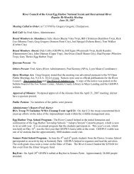
5. The long axis <strong>of</strong> the calculated zone <strong>of</strong> contribution<br />
will be aligned with the regional ground-water flow<br />
direction as shown <strong>in</strong> figure 1.<br />
The comb<strong>in</strong>ed model/CFR method comb<strong>in</strong>es<br />
the CFR calculation method def<strong>in</strong>ed above with a<br />
two-dimensional ground-water flow model that properly<br />
accounts <strong>for</strong> hydraulic gradient, aquifer transmissivity,<br />
effective porosity, aquifer saturated<br />
thickness, aquifer anisotropy, pump<strong>in</strong>g rate <strong>of</strong> the<br />
<strong>well</strong>, and time <strong>of</strong> travel.<br />
The follow<strong>in</strong>g steps will be taken:<br />
1. The CFR <strong>for</strong> Tier 1 and Tier 2 will be calculated as<br />
described <strong>in</strong> the CFR calculation method. No CFR<br />
<strong>for</strong> Tier 3 is used <strong>in</strong> this method.<br />
2. Determ<strong>in</strong>e the regional hydraulic gradient (see<br />
page 13).<br />
a. The hydraulic gradient magnitude and direction<br />
will be calculated from a regional<br />
water-table map, when available, over a<br />
distance from the <strong>well</strong> to one-mile upgradient<br />
<strong>of</strong> the <strong>well</strong>.<br />
b. When no satisfactory regional water table<br />
map is available, the hydraulic gradient<br />
magnitude may be estimated by multiply<strong>in</strong>g<br />
the topographic gradient, calculated over a<br />
distance from the <strong>well</strong> to one-mile upgradient<br />
<strong>of</strong> the <strong>well</strong>, by 0.5. In some aquifers, especially<br />
bedrock aquifers, a reasonable<br />
estimate <strong>of</strong> the regional hydraulic gradient<br />
may not be possible. In these cases, the gradient<br />
may be set to zero.<br />
Figure 1 : Long axis <strong>of</strong> zone <strong>of</strong> contribution is<br />
aligned <strong>in</strong> the direction <strong>of</strong> the regional ground-water<br />
flow direction<br />
6. A 20-degree angle <strong>of</strong> rotation, or an angle <strong>of</strong> rotation<br />
determ<strong>in</strong>ed from site-specific data, will be applied<br />
to the model results. The results will be rotated,<br />
us<strong>in</strong>g the <strong>well</strong> as the pivot po<strong>in</strong>t, by the angle <strong>of</strong> rotation<br />
both clockwise and counter-clockwise, <strong>for</strong> each<br />
tier as shown <strong>in</strong> figure 2. For a discussion <strong>of</strong> "angle<br />
<strong>of</strong> rotation", see hydraulic gradient <strong>in</strong> the Data Selection<br />
and Parameter Estimation section <strong>of</strong> this report.<br />
7. The CFR portion <strong>of</strong> the WHPA will be superimposed<br />
on the results <strong>of</strong> the ground-water model portion<br />
<strong>of</strong> the WHPA as shown <strong>in</strong> figure 3. The CFR<br />
component was added to account <strong>for</strong> potential <strong>in</strong>accuracies<br />
<strong>in</strong> estimat<strong>in</strong>g <strong>well</strong> characteristics and properties<br />
<strong>of</strong> the aquifer, as <strong>well</strong> as to account <strong>for</strong><br />
potential pump<strong>in</strong>g <strong>in</strong>terference effects which are<br />
common at public water systems <strong>in</strong> New Jersey.<br />
8. The result<strong>in</strong>g outer boundary <strong>of</strong> the comb<strong>in</strong>ed CFR<br />
and ground-water model portions will then be established<br />
<strong>for</strong> each tier as shown <strong>in</strong> figure 4.<br />
9
Figure 2. Clockwise and counter-clockwise 20-<br />
degree angle <strong>of</strong> rotation applied to calculated zone <strong>of</strong><br />
contribution us<strong>in</strong>g the <strong>well</strong> as the pivot po<strong>in</strong>t.<br />
Figure 3. CFR portion <strong>of</strong> WHPA superimposed on<br />
the results <strong>of</strong> the ground-water model portion <strong>of</strong> the<br />
WHPA.<br />
Protection Areas, March 1991." The model is available<br />
through the International Ground Water Model<strong>in</strong>g<br />
Center, Colorado School <strong>of</strong> M<strong>in</strong>es, Golden,<br />
Colorado, 80401-1887. The appropriate <strong>well</strong> pump<strong>in</strong>g<br />
rate and aquifer values <strong>for</strong> saturated thickness,<br />
hydraulic conductivity, hydraulic gradient and magnitude,<br />
and effective porosity are critical to per<strong>for</strong>m<br />
the model. Site-specific data, especially <strong>for</strong> hydraulic<br />
gradient, <strong>in</strong>crease the level <strong>of</strong> model accuracy. Selection<br />
<strong>of</strong> these values is discussed <strong>in</strong> the Data Selection<br />
and Parameter Estimation section.<br />
The NJGS has developed a computer program<br />
called "OUTPATH" that will apply the angle <strong>of</strong> rotation<br />
and aquifer anisotropy to outputs from the<br />
RESSQC version <strong>of</strong> the EPA WHPA model and create<br />
a file <strong>of</strong> the WHPA that can be <strong>in</strong>corporated <strong>in</strong>to a<br />
geographic <strong>in</strong><strong>for</strong>mation system (GIS). It is available<br />
upon request from NJGS.<br />
Non-CFR Model Method<br />
When a regional water table map is available<br />
and aquifer recharge and <strong>well</strong> <strong>in</strong>terference are accounted<br />
<strong>for</strong> <strong>in</strong> the model, no CFR is needed <strong>for</strong> the<br />
WHPA <strong>del<strong>in</strong>eation</strong>. The non-CFR model method<br />
will use a two-dimensional ground-water flow model<br />
that properly accounts <strong>for</strong> hydraulic-<strong>head</strong> distribution,<br />
aquifer recharge, <strong>well</strong> <strong>in</strong>terference, aquifer<br />
transmissivity, effective porosity, aquifer saturated<br />
thickness, pump<strong>in</strong>g rate <strong>of</strong> the <strong>well</strong>, time <strong>of</strong> travel,<br />
aquifer anisotropy, hydrologic boundaries, and aquifer<br />
heterogeneities.<br />
Figure 4. Result<strong>in</strong>g outer boundary <strong>of</strong> the comb<strong>in</strong>ed<br />
CFR and model portions established <strong>for</strong> each tier <strong>of</strong><br />
the WHPA <strong>del<strong>in</strong>eation</strong>.<br />
9. The outer boundary <strong>of</strong> the WHPA <strong>del<strong>in</strong>eation</strong> may<br />
be truncated by appropriate hydrologic boundaries<br />
such as major rivers and aquifer boundaries. The<br />
result<strong>in</strong>g boundary will be the WHPA <strong>del<strong>in</strong>eation</strong> <strong>for</strong><br />
the <strong>well</strong>, which will be drawn accord<strong>in</strong>g to the <strong>del<strong>in</strong>eation</strong><br />
mapp<strong>in</strong>g requirements section.<br />
An example <strong>of</strong> the type <strong>of</strong> model the Department<br />
and others may use as part <strong>of</strong> this method is the<br />
RESSQC portion <strong>of</strong> the EPA WHPA Model, def<strong>in</strong>ed<br />
<strong>in</strong> the publication, "WHPA: A Modular Semi-<br />
Analytical Model <strong>for</strong> the Del<strong>in</strong>eation <strong>of</strong> Well Head<br />
10<br />
The follow<strong>in</strong>g steps will be taken:<br />
1. For advanced <strong>del<strong>in</strong>eation</strong>s requir<strong>in</strong>g a model grid,<br />
the grid cells should be sized to allow accurate locations<br />
<strong>of</strong> pump<strong>in</strong>g <strong>well</strong>s and the result<strong>in</strong>g groundwater<br />
flow paths. Grid cells conta<strong>in</strong><strong>in</strong>g pump<strong>in</strong>g<br />
<strong>well</strong>s should be no greater than 100 feet <strong>in</strong> length or<br />
width. The maximum allowable length or width <strong>of</strong> a<br />
grid cell <strong>in</strong> any such model will be 500 feet. The<br />
maximum allowable thickness <strong>of</strong> any layer <strong>in</strong> the<br />
model will be 100 feet. The model should be subject<br />
to a sensitivity analysis, and be calibrated, <strong>in</strong> a manner<br />
acceptable to the Department, so that simulated<br />
results are acceptably close to field conditions.<br />
2. The ground-water flow model will be used to calculate<br />
the zone <strong>of</strong> contribution <strong>of</strong> the <strong>well</strong> <strong>for</strong> the<br />
times <strong>of</strong> travel established <strong>for</strong> Tier 1, Tier 2, and Tier<br />
3 as shown <strong>in</strong> figure 5.<br />
3. A 20-degree angle <strong>of</strong> rotation, or an angle <strong>of</strong> rotation<br />
determ<strong>in</strong>ed from site-specific data, will be applied<br />
to the model results. The results will be rotated,<br />
us<strong>in</strong>g the <strong>well</strong> as the pivot po<strong>in</strong>t, by the angle <strong>of</strong> ro-
tation <strong>of</strong> rotation both clockwise and counterclockwise,<br />
<strong>for</strong> each tier as shown <strong>in</strong> figure 6.<br />
4. The outer boundary <strong>of</strong> the WHPA <strong>del<strong>in</strong>eation</strong> may<br />
be truncated by appropriate hydrologic boundaries if<br />
warranted. The result<strong>in</strong>g outer boundary <strong>of</strong> the rotated<br />
tiers will then be established as shown <strong>in</strong> figure<br />
7. This will be the WHPA <strong>del<strong>in</strong>eation</strong> <strong>for</strong> the <strong>well</strong>,<br />
which will be drawn accord<strong>in</strong>g to the <strong>del<strong>in</strong>eation</strong><br />
mapp<strong>in</strong>g requirements section.<br />
Three-Dimensional Model Method<br />
The three-dimensional model method will use a<br />
three-dimensional, numerical ground-water flow<br />
model that properly accounts <strong>for</strong> hydraulic-<strong>head</strong> distribution,<br />
aquifer transmissivity, effective porosity,<br />
aquifer saturated thickness, pump<strong>in</strong>g rate <strong>of</strong> the <strong>well</strong>,<br />
time <strong>of</strong> travel, partial penetration <strong>of</strong> the aquifer by the<br />
pump<strong>in</strong>g <strong>well</strong>, <strong>well</strong> <strong>in</strong>terference, hydrologic boundaries,<br />
aquifer recharge, aquifer heterogeneities, aquifer<br />
anisotropy, and any other relevant site-specific conditions,<br />
as appropriate <strong>for</strong> the area surround<strong>in</strong>g the<br />
<strong>well</strong>.<br />
The follow<strong>in</strong>g steps will be taken:<br />
Figure 5. Non-CFR model method zone <strong>of</strong> contribution<br />
example.<br />
1. For advanced <strong>del<strong>in</strong>eation</strong>s requir<strong>in</strong>g a model grid,<br />
the grid cells should be sized to allow accurate locations<br />
<strong>of</strong> pump<strong>in</strong>g <strong>well</strong>s and the result<strong>in</strong>g groundwater<br />
flow paths. Grid cells conta<strong>in</strong><strong>in</strong>g pump<strong>in</strong>g<br />
<strong>well</strong>s should be no greater than 100 feet <strong>in</strong> length or<br />
width. The maximum allowable length or width <strong>of</strong> a<br />
grid cell <strong>in</strong> any such model will be 500 feet. The<br />
maximum allowable thickness <strong>of</strong> any layer <strong>in</strong> the<br />
model will be 100 feet. A sensitivity analysis and<br />
calibration should be per<strong>for</strong>med on the model, <strong>in</strong> a<br />
manner acceptable to the Department, so that simulated<br />
results are acceptably close to field conditions.<br />
2. The ground-water flow model will be used to calculate<br />
the zone <strong>of</strong> contribution <strong>of</strong> the <strong>well</strong> <strong>for</strong> the<br />
times <strong>of</strong> travel established <strong>for</strong> Tier 1, Tier 2, and Tier<br />
3 as shown <strong>in</strong> figure 5.<br />
Figure 6. Clockwise and counter-clockwise 20-<br />
degree angle <strong>of</strong> rotation applied to non-CFR model<br />
method <strong>of</strong> contribution us<strong>in</strong>g the <strong>well</strong> as the pivot<br />
po<strong>in</strong>t.<br />
3. A 20-degree angle <strong>of</strong> rotation, or an angle <strong>of</strong> rotation<br />
determ<strong>in</strong>ed from site-specific data, will be applied<br />
to the model results. The results will be rotated,<br />
us<strong>in</strong>g the <strong>well</strong> as the pivot po<strong>in</strong>t, by the angle <strong>of</strong> rotation<br />
both clockwise and counter-clockwise, <strong>for</strong> each<br />
tier as shown <strong>in</strong> figure 6. When us<strong>in</strong>g the threedimensional<br />
model method, the rotated area should<br />
be truncated by appropriate hydrologic boundaries.<br />
4. The result<strong>in</strong>g outer boundary <strong>of</strong> the rotated tiers<br />
will then be established as shown <strong>in</strong> figure 7. This<br />
will be the WHPA <strong>del<strong>in</strong>eation</strong> <strong>for</strong> the <strong>well</strong>, which<br />
will be drawn accord<strong>in</strong>g to the <strong>del<strong>in</strong>eation</strong> mapp<strong>in</strong>g<br />
requirements section.<br />
Figure 7. Outer boundaries <strong>of</strong> the rotated tiers are<br />
established as the WHPA <strong>del<strong>in</strong>eation</strong>.<br />
5. As an alternative to <strong>in</strong>corporat<strong>in</strong>g an angle <strong>of</strong> rotation<br />
when us<strong>in</strong>g the three-dimensional model method,<br />
a systematic evaluation <strong>of</strong> the model sensitivity to<br />
different comb<strong>in</strong>ations <strong>of</strong> model parameters, over<br />
appropriate ranges, may be conducted. This should<br />
<strong>in</strong>clude seasonal and spatial variation <strong>of</strong> appropriate<br />
model-<strong>in</strong>put parameters. This will require del<strong>in</strong>eat<strong>in</strong>g<br />
a WHPA <strong>for</strong> each acceptable comb<strong>in</strong>ation. The outer<br />
limits <strong>of</strong> the result<strong>in</strong>g <strong>in</strong>dividual tier <strong>del<strong>in</strong>eation</strong>s will<br />
11
constitute the WHPA, which will be drawn accord<strong>in</strong>g<br />
to the Del<strong>in</strong>eation Mapp<strong>in</strong>g Requirements section.<br />
Advanced Del<strong>in</strong>eations and WHPA Revisions<br />
The <strong>del<strong>in</strong>eation</strong> methods <strong>in</strong> this report reflect a<br />
hierarchy <strong>of</strong> <strong>in</strong>creas<strong>in</strong>g degree <strong>of</strong> model<strong>in</strong>g sophistication<br />
and <strong>in</strong>creas<strong>in</strong>g data requirements <strong>for</strong> the model<br />
used to del<strong>in</strong>eate the WHPA. The pr<strong>in</strong>ciple beh<strong>in</strong>d<br />
this <strong>del<strong>in</strong>eation</strong> hierarchy is to achieve an <strong>in</strong>creas<strong>in</strong>g<br />
degree <strong>of</strong> accuracy <strong>for</strong> the WHPA to the degree that<br />
methods and available data allow improved simulation<br />
<strong>of</strong> real hydrologic conditions.<br />
The concept <strong>of</strong> per<strong>for</strong>m<strong>in</strong>g advanced <strong>del<strong>in</strong>eation</strong>s<br />
is based on two pr<strong>in</strong>ciples. First, where data are<br />
available, an advanced <strong>del<strong>in</strong>eation</strong> will likely provide<br />
a WHPA that is more accurate. Secondly, it is conceivable<br />
that an <strong>in</strong>terested party, such as a water purveyor<br />
or a regulated potential or exist<strong>in</strong>g pollutant<br />
source, may wish to per<strong>for</strong>m an advanced <strong>del<strong>in</strong>eation</strong><br />
to provide certa<strong>in</strong>ty regard<strong>in</strong>g the application <strong>of</strong> a<br />
WHPA to a specific geographic location. Situations<br />
such as a <strong>well</strong> that receives a portion <strong>of</strong> its water<br />
from a nearby river that has good hydraulic connection<br />
to the aquifer, or a <strong>well</strong> field that is affected by<br />
<strong>well</strong> <strong>in</strong>terference are also good candidates <strong>for</strong> an advanced<br />
<strong>del<strong>in</strong>eation</strong>.<br />
Because the Department will be per<strong>for</strong>m<strong>in</strong>g<br />
WHPA <strong>del<strong>in</strong>eation</strong>s on all public water system <strong>well</strong>s,<br />
only <strong>del<strong>in</strong>eation</strong>s submitted by outside parties, which<br />
are completed at a level higher than that undertaken<br />
by the Department will be reviewed.<br />
Interested parties who feel that a more advanced<br />
<strong>del<strong>in</strong>eation</strong> <strong>for</strong> a NCWS <strong>well</strong> is required, and volunteer<br />
to per<strong>for</strong>m a WHPA <strong>del<strong>in</strong>eation</strong>, will use the<br />
same methods used <strong>for</strong> CWS <strong>well</strong> <strong>del<strong>in</strong>eation</strong>s.<br />
The three-dimensional model method, which<br />
uses a numerical model, is the highest level <strong>of</strong><br />
WHPA methods described <strong>in</strong> this report because it<br />
has the potential to <strong>in</strong>corporate and evaluate all components<br />
<strong>of</strong> the ground-water system around the<br />
pump<strong>in</strong>g <strong>well</strong>. The Department does not necessarily<br />
consider numerical model<strong>in</strong>g superior to all other<br />
techniques <strong>for</strong> all applications. Numerical model<strong>in</strong>g<br />
is costly and data <strong>in</strong>tensive. It may not automatically<br />
result <strong>in</strong> <strong>del<strong>in</strong>eation</strong>s that are measurably superior to<br />
less rigorous and less time-<strong>in</strong>tensive analytical and<br />
semi-analytical methods, but, when done properly<br />
with good site-specific data, it may provide significant<br />
<strong>in</strong>sights <strong>in</strong>to the location <strong>of</strong> the WHPA.<br />
For public water-supply <strong>well</strong>s with an exist<strong>in</strong>g<br />
WHPA <strong>del<strong>in</strong>eation</strong> completed by the Department, the<br />
method selected <strong>for</strong> a revised <strong>del<strong>in</strong>eation</strong> should meet<br />
the follow<strong>in</strong>g requirements:<br />
1. The method should be selected from the methods<br />
def<strong>in</strong>ed <strong>in</strong> this report and meet the selection requirements<br />
listed <strong>in</strong> the Del<strong>in</strong>eation Method Selection<br />
section; and<br />
2. The method should be a more advanced method<br />
than that used <strong>for</strong> the <strong>del<strong>in</strong>eation</strong> <strong>of</strong> the exist<strong>in</strong>g<br />
WHPA, or must be an equivalent method used with<br />
more reliable site-specific data, as determ<strong>in</strong>ed by the<br />
Department.<br />
3. For advanced <strong>del<strong>in</strong>eation</strong>s requir<strong>in</strong>g a model grid,<br />
the grid cells must be sized to allow accurate locations<br />
<strong>of</strong> pump<strong>in</strong>g <strong>well</strong>s and the result<strong>in</strong>g groundwater<br />
flow paths. Grid cells conta<strong>in</strong><strong>in</strong>g pump<strong>in</strong>g<br />
<strong>well</strong>s must be no greater than 100 feet <strong>in</strong> length or<br />
width. The maximum allowable length or width <strong>of</strong> a<br />
cell <strong>in</strong> any such model will be 500 feet. The maximum<br />
allowable thickness <strong>of</strong> any layer <strong>in</strong> the model<br />
will be 100 feet.<br />
The Department <strong>in</strong>tends to rely upon the<br />
American Society <strong>for</strong> Test<strong>in</strong>g and Materials (ASTM)<br />
ground-water model<strong>in</strong>g standards listed <strong>in</strong> the resource<br />
section <strong>of</strong> this report. Ground-water pr<strong>of</strong>essionals<br />
submitt<strong>in</strong>g WHPA’s should follow these<br />
standards.<br />
Data Selection and Parameter Estimation<br />
The selection <strong>of</strong> values <strong>for</strong> hydraulic gradient,<br />
aquifer transmissivity, effective porosity, aquifer<br />
saturated thickness, pump<strong>in</strong>g rate, <strong>well</strong> radius and<br />
anisotropy <strong>for</strong> all <strong>del<strong>in</strong>eation</strong>s must be <strong>in</strong> accordance<br />
with the order specified <strong>in</strong> table 2. For all WHPA<br />
methods, each variable listed <strong>in</strong> table 2 should be<br />
selected, when feasible, based on the first selection<br />
procedure given <strong>in</strong> table 2. If the data <strong>for</strong> the first<br />
selection are not available, the second selection<br />
should be used. If the data <strong>for</strong> the second selection<br />
are not available, the third selection should be used.<br />
Where values can not be determ<strong>in</strong>ed from table 2 it<br />
may be obta<strong>in</strong>ed from the NJGS, from a published<br />
source, or other source acceptable to the Department.<br />
12
Hydraulic Gradient<br />
Hydraulic gradient has two components: magnitude<br />
and direction. The magnitude is measured as<br />
the slope <strong>of</strong> the water table, represent<strong>in</strong>g the change<br />
<strong>in</strong> elevation <strong>of</strong> the water table over a unit distance.<br />
The direction <strong>of</strong> the hydraulic gradient, <strong>of</strong>ten referred<br />
to as the "angle <strong>of</strong> ambient flow," is the azimuth <strong>of</strong><br />
the maximum slope <strong>of</strong> the water table at a specific<br />
po<strong>in</strong>t.<br />
The hydraulic gradient varies over space and<br />
time, and is affected by a variety <strong>of</strong> local and regional<br />
factors. For WHPA <strong>del<strong>in</strong>eation</strong> purposes, the regional<br />
hydraulic gradient is the most useful.<br />
For some <strong>del<strong>in</strong>eation</strong> methods, the hydraulic<br />
gradient magnitude and direction will be calculated<br />
from a regional water-table map <strong>in</strong> the area upgradient<br />
<strong>of</strong> the <strong>well</strong> over a distance <strong>of</strong> one mile. The distance<br />
<strong>of</strong> one mile was selected as representative <strong>of</strong> a<br />
"regional" gradient, and is reasonable when compared<br />
to the calculated lengths <strong>of</strong> typical WHPA’s<br />
represent<strong>in</strong>g hydrogeologic and operational conditions<br />
found <strong>in</strong> New Jersey.<br />
In <strong>in</strong>stances where it is difficult to calculate the<br />
hydraulic gradient with<strong>in</strong> a one-mile span due to<br />
rapid changes <strong>in</strong> the water-table gradient or direction,<br />
or due to the location <strong>of</strong> hydrologic boundaries, the<br />
gradient magnitude and direction will be calculated<br />
over an appropriate distance <strong>of</strong> less than one mile.<br />
In <strong>areas</strong> <strong>of</strong> the State where regional water-table<br />
maps do not exist, the magnitude and direction <strong>of</strong> the<br />
regional hydraulic gradient may be approximated<br />
based on topography, <strong>in</strong> the area upgradient <strong>of</strong> the<br />
<strong>well</strong>. This is determ<strong>in</strong>ed by us<strong>in</strong>g the change <strong>in</strong> land<br />
surface elevation over a distance <strong>of</strong> one mile <strong>in</strong> the<br />
aquifer from which the <strong>well</strong> is pump<strong>in</strong>g. This approach<br />
recognizes that the water table is usually a<br />
subdued replica <strong>of</strong> topography.<br />
Topographic and hydraulic gradients <strong>for</strong> selected<br />
<strong>in</strong>tervals were compared <strong>for</strong> 128 l<strong>in</strong>e segments<br />
each approximately one mile <strong>in</strong> length.<br />
A statistical analysis <strong>of</strong> these data suggested<br />
that a reasonable estimate <strong>of</strong> the hydraulic gradient <strong>in</strong><br />
the Coastal Pla<strong>in</strong> could be obta<strong>in</strong>ed by multiply<strong>in</strong>g<br />
the topographic gradient by 0.5. Thus, a conversion<br />
factor <strong>of</strong> 0.5 will be used to convert a known topographic<br />
gradient, over a distance <strong>of</strong> one mile <strong>in</strong> the<br />
area upgradient <strong>of</strong> the <strong>well</strong>, to the hydraulic gradient<br />
magnitude, when lack<strong>in</strong>g a regional water-table map.<br />
Research will cont<strong>in</strong>ue to better def<strong>in</strong>e this relationship<br />
<strong>in</strong> other hydrogeologic regions <strong>of</strong> the State.<br />
The hydraulic gradient direction or angle <strong>of</strong><br />
ambient flow, is a very important parameter <strong>for</strong> a<br />
WHPA <strong>del<strong>in</strong>eation</strong>. In certa<strong>in</strong> hydrogeologic sett<strong>in</strong>gs,<br />
especially those with a relatively steep hydraulic<br />
gradient, small errors <strong>in</strong> selection <strong>of</strong> the angle <strong>of</strong><br />
ambient flow may cause the WHPA to be partially<br />
mislocated result<strong>in</strong>g <strong>in</strong> <strong>areas</strong> that are actually contribut<strong>in</strong>g<br />
water to the <strong>well</strong> to end up outside the<br />
WHPA. This would result <strong>in</strong> a misconception <strong>of</strong> the<br />
actual sources <strong>of</strong> water <strong>for</strong> a <strong>well</strong>.<br />
Variability and uncerta<strong>in</strong>ty <strong>in</strong> the direction <strong>of</strong><br />
ambient ground-water flow may arise from several<br />
factors, <strong>in</strong>clud<strong>in</strong>g:<br />
œ<br />
œ<br />
œ<br />
No regional water-table map is available and the<br />
angle <strong>of</strong> ambient flow is based on an estimation<br />
from the topography <strong>of</strong> the land surface.<br />
The regional water-table map used is based on a<br />
limited number <strong>of</strong> simultaneous water-level<br />
measurements or the observation po<strong>in</strong>ts are separated<br />
by large distances.<br />
Subjectivity <strong>in</strong> <strong>in</strong>terpret<strong>in</strong>g field data to construct<br />
a water-table map results <strong>in</strong> non-unique waterlevel<br />
contours.<br />
To quantify the relationship between topography<br />
and the water table, the NJGS observed topographic<br />
and hydraulic gradients <strong>in</strong> three dra<strong>in</strong>age<br />
bas<strong>in</strong>s <strong>in</strong> the New Jersey Coastal Pla<strong>in</strong> - the Great<br />
Egg Harbor, Mullica, and Toms River Bas<strong>in</strong>s.<br />
œ<br />
œ<br />
Subjectivity <strong>in</strong> estimat<strong>in</strong>g direction <strong>of</strong> hydraulic<br />
gradient from water-table maps.<br />
Temporal variations <strong>in</strong> the angle <strong>of</strong> ambient flow<br />
exist as a result <strong>of</strong> spatial or seasonal differences.<br />
13
Table 2. Selection <strong>of</strong> <strong>in</strong>put values <strong>for</strong> WHPA <strong>del<strong>in</strong>eation</strong>.<br />
DELINEATION DATA<br />
VARIABLES<br />
Hydraulic Gradient<br />
Aquifer Transmissivity<br />
Effective Porosity<br />
Aquifer Saturated Thickness<br />
Pump<strong>in</strong>g Rate<br />
Well Radius<br />
Anisotropy (Ratio) and Direction<br />
FIRST SELECTION SECOND SELECTION THIRD SELECTION<br />
Calculated from regional water-table contour map<br />
<strong>in</strong> area up-gradient <strong>of</strong> the <strong>well</strong>, with gradient<br />
magnitude and direction calculated over distance<br />
<strong>of</strong> one mile 1 . Del<strong>in</strong>eation to <strong>in</strong>clude angle <strong>of</strong><br />
rotation calculated from site-specific data.<br />
Adequate hydrologic tests from <strong>well</strong>s located<br />
with<strong>in</strong> the modeled area 2 .<br />
Adequate hydrologic tests from <strong>well</strong>s located<br />
with<strong>in</strong> the modeled area 2 .<br />
For unconsolidated aquifers, the vertical distance<br />
between the water table and the first significant<br />
conf<strong>in</strong><strong>in</strong>g layer underly<strong>in</strong>g the aquifer <strong>in</strong><br />
which the <strong>well</strong> is screened.<br />
For bedrock aquifers, the vertical distance between<br />
the water table and the bottom <strong>of</strong> the <strong>well</strong>,<br />
but no greater than 500 feet.<br />
For <strong>well</strong>s <strong>in</strong> production <strong>for</strong> at least two years, use<br />
the method below:<br />
Maximum average annual pump<strong>in</strong>g rate dur<strong>in</strong>g<br />
the period <strong>of</strong> operation, up to and <strong>in</strong>clud<strong>in</strong>g the<br />
previous 12 years, from actual pump<strong>in</strong>g data, plus<br />
a 25% safety factor, but not more than the pump<br />
capacity and not less than 40% <strong>of</strong> pump capacity.<br />
One half the f<strong>in</strong>ished diameter <strong>of</strong> the <strong>well</strong> screen<br />
or open borehole listed on the <strong>well</strong> record.<br />
Value based on adequate hydrogeologic tests and<br />
analyses <strong>of</strong> <strong>well</strong>s with<strong>in</strong> modeled area.<br />
Calculated from regional water-table contour map<br />
<strong>in</strong> area up-gradient <strong>of</strong> the <strong>well</strong>, with gradient magnitude<br />
and direction calculated over distance <strong>of</strong> one<br />
mile 1 . Del<strong>in</strong>eation to <strong>in</strong>clude +/-20 degree angle <strong>of</strong><br />
rotation.<br />
Calculated as the product <strong>of</strong> hydraulic conductivity<br />
and aquifer thickness 3 .<br />
Estimated based on total porosity and/or specific<br />
yield data from the aquifer.<br />
For unconsolidated aquifers, the vertical distance<br />
between the water table and the bottom <strong>of</strong> the <strong>well</strong>.<br />
For bedrock aquifers, the length <strong>of</strong> open borehole<br />
<strong>for</strong> the <strong>well</strong>, but not greater than 500 feet.<br />
Estimated based on the method below yield<strong>in</strong>g the<br />
lowest pump<strong>in</strong>g rate:<br />
Installed pump capacity <strong>for</strong> the <strong>well</strong>.<br />
Water allocation <strong>for</strong> the <strong>in</strong>dividual <strong>well</strong>, if available.<br />
The planned maximum average annual pump<strong>in</strong>g<br />
rate, over the next 12 years, if justified by the <strong>well</strong><br />
owner to the satisfaction <strong>of</strong> the Department.<br />
One half the f<strong>in</strong>ished diameter <strong>of</strong> the <strong>well</strong> screen or<br />
open borehole listed on <strong>well</strong> construction diagram.<br />
Value based on published values <strong>for</strong> the aquifer.<br />
Gradient magnitude and direction based on<br />
topographic gradient and 0.5 conversion factor,<br />
<strong>in</strong> area up-gradient <strong>of</strong> the <strong>well</strong> 1 . Del<strong>in</strong>eation<br />
to <strong>in</strong>clude +/-20 degree angle <strong>of</strong> rotation.<br />
Estimated based on published values <strong>for</strong> comparable<br />
aquifers.<br />
Obta<strong>in</strong>ed from effective porosity values provided<br />
<strong>for</strong> selective aquifer types <strong>in</strong> table 1.<br />
For unconsolidated aquifers, the average or<br />
median aquifer thickness <strong>for</strong> <strong>well</strong>s <strong>in</strong> this aquifer.<br />
For bedrock aquifers, the average or median<br />
aquifer thickness <strong>for</strong> <strong>well</strong>s <strong>in</strong> this aquifer.<br />
Estimated based on the number <strong>of</strong> connections<br />
serviced by the <strong>well</strong>, or the estimated population<br />
serviced by the <strong>well</strong>, with per-capita consumption<br />
at 100 gallons per day per capita,<br />
and occupancy based on census data <strong>for</strong> the<br />
specific municipality where the <strong>well</strong> is located.<br />
If the number <strong>of</strong> connections or the<br />
estimated population is not known, the average<br />
or median pump<strong>in</strong>g rate <strong>for</strong> this type <strong>of</strong><br />
<strong>well</strong> will be used.<br />
If unknown, use the radius correspond<strong>in</strong>g to<br />
the <strong>well</strong>’ s pump capacity rate listed <strong>in</strong> Driscoll,<br />
1986., Table 13.1, Ground Water and<br />
Wells, second edition.<br />
1:1 <strong>for</strong> all aquifers except the follow<strong>in</strong>g:<br />
Mesozoic sedimentary rocks 10:1; Paleozoic<br />
sedimentary rocks 3:1. Direction is bedd<strong>in</strong>g<br />
plane strike from a published geologic map.<br />
For all WHP methods, the first selection must be used if the data are available; if not available, the second selection must be used; and so on.<br />
When site-specific values can not be determ<strong>in</strong>ed from table it may be requested from the New Jersey Geological Survey, P.O. Box 427, Trenton, NJ 08625, or obta<strong>in</strong>ed from a published source or other source acceptable<br />
to the Department.<br />
1 If it is difficult to calculate the hydraulic gradient over a distance <strong>of</strong> one mile, due to rapid changes <strong>in</strong> the water-table gradient or direction, or due to the location <strong>of</strong> hydrologic boundaries, then the hydraulic gradient<br />
magnitude and direction should be calculated over an appropriate distance less than one mile.<br />
2 Tests must be adequate to permit accurate def<strong>in</strong>ition <strong>of</strong> hydrologic characteristics <strong>of</strong> the aquifer to the satisfaction <strong>of</strong> the Department.<br />
3 When calculat<strong>in</strong>g transmissivity, the hydraulic conductivity should generally be the geometric mean value <strong>for</strong> the aquifer as shown <strong>in</strong> table 3.<br />
14
<strong>in</strong> ground-water recharge or unidentified pump<strong>in</strong>g<br />
nearby.<br />
Temporal variations <strong>in</strong> the direction <strong>of</strong> groundwater<br />
flow can be quantified at locations with sufficient<br />
regional water-level monitor<strong>in</strong>g data. Such<br />
changes have been documented <strong>in</strong> published reports<br />
and have been identified as a primary cause <strong>of</strong> transverse<br />
dispersion <strong>of</strong> contam<strong>in</strong>ant plumes.<br />
To quantify expected temporal variation <strong>in</strong> hydraulic<br />
gradient directions <strong>in</strong> New Jersey aquifers,<br />
the NJGS evaluated eight sites <strong>in</strong> New Jersey with<br />
sufficient water-level monitor<strong>in</strong>g data. The selected<br />
sites covered a variety <strong>of</strong> New Jersey aquifers, <strong>in</strong>clud<strong>in</strong>g<br />
coastal pla<strong>in</strong>, bedrock and glacial aquifers.<br />
Mean hydraulic gradient directions and seasonal<br />
variations from the mean were calculated <strong>for</strong> numerous<br />
sampl<strong>in</strong>g po<strong>in</strong>ts. A statistical analysis <strong>of</strong> the data<br />
showed that the total variation <strong>in</strong> the azimuth <strong>of</strong> the<br />
flow direction was as much as 48 degrees (24 degrees<br />
on either side <strong>of</strong> the mean) over a two year period.<br />
Based on this analysis, a 16.4-degree range on either<br />
side <strong>of</strong> the mean hydraulic gradient direction would<br />
sufficiently account <strong>for</strong> the variability result<strong>in</strong>g from<br />
temporal variation <strong>in</strong> hydraulic gradient direction at<br />
90% <strong>of</strong> the sites.<br />
To account <strong>for</strong> the variability <strong>in</strong> the accuracy <strong>of</strong><br />
the selected angle <strong>of</strong> ambient flow, aris<strong>in</strong>g from both<br />
temporal variation and the other potential uncerta<strong>in</strong>ties<br />
listed above, a range <strong>of</strong> 20 degrees on either side<br />
<strong>of</strong> the selected angle <strong>of</strong> ambient flow will be used <strong>in</strong><br />
del<strong>in</strong>eat<strong>in</strong>g WHPA’s. The variability associated with<br />
the angle <strong>of</strong> ambient flow will be factored <strong>in</strong>to the<br />
WHPA <strong>del<strong>in</strong>eation</strong> process by rotat<strong>in</strong>g the del<strong>in</strong>eated<br />
WHPA, with the <strong>well</strong> as the pivot po<strong>in</strong>t, 20 degrees<br />
<strong>in</strong> both a clockwise and counter-clockwise direction.<br />
The total rotation will be 40 degrees. The entire area<br />
encompassed by the rotation is <strong>in</strong>cluded <strong>in</strong> the<br />
WHPA. However, the rotated area should be truncated<br />
by appropriate hydrologic boundaries when<br />
such data are available. This 20-degree "angle <strong>of</strong><br />
rotation" will be used <strong>for</strong> all WHPA <strong>del<strong>in</strong>eation</strong>s unless<br />
sufficient site-specific data justify the use <strong>of</strong> a<br />
smaller or larger angle <strong>of</strong> rotation or if the threedimensional<br />
model method is used with the alternative<br />
described <strong>in</strong> item 5 <strong>of</strong> the Three-Dimensional<br />
Model Method section (page 12). The angle can be<br />
changed if sufficient evidence, cover<strong>in</strong>g the seasonal<br />
fluctuation phenomena, is presented as part <strong>of</strong> the<br />
<strong>del<strong>in</strong>eation</strong>.<br />
15<br />
Calculation <strong>of</strong> a site-specific angle <strong>of</strong> rotation<br />
requires a network <strong>of</strong> observation <strong>well</strong>s acceptable to<br />
the Department, with a m<strong>in</strong>imum <strong>of</strong> one year <strong>of</strong><br />
quarterly water-level data, water-table maps, and<br />
calculated hydraulic gradient directions. The calculated<br />
site-specific angle <strong>of</strong> rotation will be equal to<br />
the total variation <strong>in</strong> the azimuth <strong>of</strong> ground-water<br />
flow directions observed <strong>in</strong> the data.<br />
The NJGS has developed a computer program<br />
called "OUTPATH" that will apply the angle <strong>of</strong> rotation<br />
to outputs from the RESSQC version <strong>of</strong> the EPA<br />
WHPA model and create a file <strong>of</strong> the WHPA that can<br />
be <strong>in</strong>corporated <strong>in</strong>to a geographic <strong>in</strong><strong>for</strong>mation system<br />
(GIS). It is available upon request from NJGS.<br />
Transmissivity<br />
Transmissivity is a measure <strong>of</strong> the quantity <strong>of</strong><br />
water that an aquifer can transmit over its saturated<br />
thickness per unit width (that is, one foot) and a hydraulic<br />
gradient <strong>of</strong> one. In mathematical terms,<br />
transmissivity is equal to the product <strong>of</strong> the thickness<br />
and hydraulic conductivity <strong>of</strong> the aquifer.<br />
For WHPA calculation, the aquifer’s transmissivity<br />
will be selected based on adequate hydrologic<br />
tests from <strong>well</strong>s located with<strong>in</strong> the modeled area. In<br />
<strong>areas</strong> where transmissivity values are not readily<br />
available, transmissivity should generally be obta<strong>in</strong>ed<br />
by multiply<strong>in</strong>g the aquifer thickness by the geometric<br />
mean <strong>of</strong> hydraulic conductivity values measured <strong>in</strong><br />
the aquifer <strong>of</strong> <strong>in</strong>terest. Currently available hydraulic<br />
conductivity and transmissivity values <strong>for</strong> New Jersey<br />
aquifers are listed <strong>in</strong> tables 3 and 4. Where no<br />
data <strong>for</strong> a given <strong>for</strong>mation or aquifer are available <strong>in</strong><br />
tables 3 and 4, published values <strong>for</strong> similar aquifers<br />
may be used.<br />
Effective Porosity<br />
Porosity is important <strong>in</strong> ground-water hydrology<br />
because it tells us the maximum amount <strong>of</strong> water that<br />
an aquifer can conta<strong>in</strong> when it is saturated. Porosity<br />
is the ratio <strong>of</strong> the volume <strong>of</strong> void spaces (that is,<br />
pores, or the space not occupied by solid matter) to<br />
the total volume <strong>of</strong> an aquifer. Porosity is expressed<br />
as a decimal fraction or as a percentage, such as 0.25<br />
or 25%. Porosity <strong>in</strong> unconsolidated sand and gravel<br />
aquifers is derived from the spaces between gra<strong>in</strong>s.<br />
Porosity <strong>in</strong> consolidated bedrock aquifers (limestone,<br />
marble, shale, sandstone, granite and gneiss <strong>for</strong> example)<br />
is largely derived from fractures such as<br />
jo<strong>in</strong>ts, faults, and other tabular open<strong>in</strong>gs along bedd<strong>in</strong>g<br />
planes. Only a part <strong>of</strong> this water is available to<br />
supply a <strong>well</strong>. A portion <strong>of</strong> an aquifer’s overall porosity<br />
will not release or transmit water, due to the<br />
water be<strong>in</strong>g held <strong>in</strong> some pores by capillary tension,<br />
or because <strong>of</strong> dead-end pore space which does not<br />
transmit water to a <strong>well</strong>. This portion or percentage<br />
<strong>of</strong> pore space is called specific retention, because<br />
water is reta<strong>in</strong>ed there and not released. Some clays<br />
have high specific retention (up to 48%), while sand,<br />
gravel and consolidated rock have low specific reten-
tion (rang<strong>in</strong>g from less than 1% <strong>in</strong> solid rock to 3% <strong>in</strong><br />
sand) (Heath, 1983). The portion <strong>of</strong> porosity that<br />
dra<strong>in</strong>s or transmits water under <strong>in</strong>fluence <strong>of</strong> gravity<br />
or due to pump<strong>in</strong>g a <strong>well</strong> is called effective porosity.<br />
This is the percentage <strong>of</strong> the aquifer’ s pore space or<br />
storage available to supply a pump<strong>in</strong>g <strong>well</strong>. Effective<br />
porosity is largest <strong>for</strong> sand and gravel (around 25%)<br />
and usually lowest <strong>for</strong> clay, silt, and bedrock (around<br />
2%).<br />
Of all the parameters necessary <strong>for</strong> del<strong>in</strong>eat<strong>in</strong>g<br />
WHPA's, porosity and effective porosity is the most<br />
difficult to measure and quantify. The preferred<br />
method <strong>for</strong> quantify<strong>in</strong>g effective porosity requires<br />
hydrologic tests at the <strong>well</strong> site, <strong>in</strong>clud<strong>in</strong>g pump<strong>in</strong>g<br />
tests, material analysis, and tracer test<strong>in</strong>g. For example,<br />
the effective porosity may be calculated based on<br />
its relationship with hydraulic conductivity (K), hydraulic<br />
gradient (i), and ground water velocity (v), <strong>in</strong><br />
accordance with Darcy's Law, such that:<br />
(n e ) = [K * i] / v<br />
At present, there are few published values <strong>of</strong> effective<br />
porosity <strong>for</strong> aquifers <strong>in</strong> New Jersey. Ongo<strong>in</strong>g<br />
research be<strong>in</strong>g conducted by the USGS and the NJGS<br />
should beg<strong>in</strong> to fill this data gap. When detailed sitespecific<br />
data or detailed aquifer specific data <strong>of</strong> porosity<br />
are not available, an effective porosity value<br />
will be obta<strong>in</strong>ed from the values provided <strong>in</strong> table 1<br />
<strong>of</strong> this report. The values <strong>in</strong> table 1 were determ<strong>in</strong>ed<br />
based on review <strong>of</strong> worldwide values <strong>of</strong> effective<br />
porosity from published sources <strong>in</strong>clud<strong>in</strong>g groundwater<br />
tracer tests conducted <strong>in</strong> the field and laboratory<br />
tests <strong>of</strong> aquifer materials. Effective porosity values<br />
<strong>for</strong> unconsolidated aquifers such as glacial<br />
stratified drift, and coastal pla<strong>in</strong> aquifers, have been<br />
estimated to be 25% (table 1a). Effective porosity<br />
values <strong>for</strong> the rock aquifers <strong>of</strong> New Jersey, such as<br />
those <strong>in</strong> shale, limestone, sandstone, gneiss and granite,<br />
have been estimated to be 2% (table 1b). Due to<br />
the current lack <strong>of</strong> site-specific data, <strong>in</strong> develop<strong>in</strong>g<br />
WHPA’ s <strong>for</strong> public supply <strong>well</strong>s, NJGS exclusively<br />
used the effective porosity values noted <strong>in</strong> table 1a<br />
and.1b.<br />
16
Table 3. Summary <strong>of</strong> horizontal conductivity (k) values <strong>for</strong> geologic and hydrogeologic units <strong>in</strong> New Jersey as <strong>of</strong><br />
January 2002.<br />
Number Arithmetic M<strong>in</strong>imum Maximum Median Standard<br />
Geologic Unit<br />
<strong>of</strong> tests mean (ft/d) (ft/d) (ft/d) (ft/d) deviation<br />
Outwash deposits 1 177.00 177.00 177.00<br />
Deltaic sediment 1 59.00 59.00 59.00<br />
Fluvial over lacustr<strong>in</strong>e sediment 1 110.00 110.00 110.00<br />
Till (Quaternary) 1 32.00 32.00 32.00<br />
Till (late Wiscons<strong>in</strong>an) 1 142.90 142.90 142.90<br />
Stratified drift 5 158.20 55.00 215.00 188.00 65.73<br />
Glaciolacustr<strong>in</strong>e sand and gravel 1 267.00 267.00 267.00<br />
Glaciolacustr<strong>in</strong>e sand and gravel (late<br />
Wiscons<strong>in</strong>an)<br />
1 285.00 285.00 285.00<br />
Glaciolacustr<strong>in</strong>e sand and gravel (Ill<strong>in</strong>oian)<br />
1 28.00 28.00 28.00<br />
Cohansey Formation 11 125.25 52.00 216.00 116.70 55.73<br />
Cohansey & Kirkwood Formations 5 152.20 98.00 200.00 160.00 48.07<br />
Kirkwood Formation - lower member<br />
(sand facies)<br />
5 110.60 22.00 334.00 57.00 126.86<br />
Kirkwood Formation 4 179.00 80.00 365.00 135.50 127.63<br />
Shark River Formation - Toms River<br />
member<br />
1 32.00 32.00 32.00<br />
Mount Laurel Formation 1 41.00 41.00 41.00<br />
Mount Laurel and Wenonah Formations 3 12.17 7.00 20.50 9.00 7.29<br />
Magothy, Raritan, and Potomac Formations<br />
1 13.00 13.00 13.00<br />
Magothy Formation 6 119.85 19.00 314.00 66.90 116.73<br />
Raritan Formation 2 72.90 71.60 74.20 72.90 1.84<br />
Potomac Formation 1 49.00 49.00 49.00<br />
Potomac Formation, Unit 3 (upper subsurface)<br />
1 153.00 153.00 153.00<br />
Brunswick Group (Passaic Formation<br />
through Boonton Formation)<br />
1 0.54 0.54 0.54<br />
Towaco Formation 1 5.00 5.00 5.00<br />
Passaic Formation 1 2.51 2.51 2.51<br />
Leithsville Formation 1 21.00 21.00 21.00<br />
Leithsville Formation and Hardyston<br />
quartzite, undivided<br />
1 13.50 13.50 13.50<br />
late Proterozoic rocks, undifferentiated 1 0.05 0.05 0.05<br />
Hornblende granite 1 0.51 0.51 0.51<br />
Pyroxene granite 1 0.58 0.58 0.58<br />
Hydrogeologic unit<br />
Number Arithmetic M<strong>in</strong>imum Maximum Media Standard<br />
<strong>of</strong> tests mean (ft/d) (ft/d) (ft/d) (ft/d) deviation<br />
cont<strong>in</strong>ous or discont<strong>in</strong>ous till 2 87.45 32.00 142.90 87.45 78.42<br />
glacial sand and gravel 11 156.09 28.00 285.00 177.00 86.38<br />
Cohansey aquifer 1 216.00 216.00 216.00<br />
Kirkwood-Cohansey water-table aquifer<br />
system<br />
16 129.80 52.00 200.00 133.89 49.12<br />
Rio Grande water-bear<strong>in</strong>g zone 3 187.33 80.00 365.00 117.00 154.97<br />
Atlantic City "800-foot" sand aquifer 5 110.60 22.00 334.00 57.00 126.86<br />
P<strong>in</strong>ey Po<strong>in</strong>t aquifer 1 32.00 32.00 32.00<br />
Mount Laurel-Wenonah aquifer 4 19.38 7.00 41.00 14.75 15.60<br />
Potomac-Raritan-Magothy aquifer system<br />
1 13.00 13.00 13.00<br />
upper Potomac-Raritan-Magothy aquifer 6 119.85 19.00 314.00 66.90 116.73<br />
middle Potomac-Raritan-Magothy aquifer<br />
2 72.90 71.60 74.20 72.90 1.84<br />
lower Potomac-Raritan-Magothy aquifer 2 101.00 49.00 153.00 101.00 73.54<br />
Brunswick aquifer 3 2.68 0.54 5.00 2.51 2.24<br />
Jacksonburg limestone, Kittat<strong>in</strong>ny Supergroup<br />
and Hardyston quartzite<br />
2 17.25 13.50 21.00 17.25 5.30<br />
igneous and metamorphic rocks 3 0.38 0.05 0.58 0.51 0.29<br />
Not all aquifers <strong>in</strong> New Jersey are represented on table 3, because some have not been tested or analyzed.<br />
17
Table 4. Summary <strong>of</strong> transmissivity values <strong>for</strong> geologic and hydrogeologic units <strong>in</strong> New Jersey as <strong>of</strong> January 2002.<br />
Geologic Unit<br />
Number<br />
<strong>of</strong> tests<br />
Arithmetic<br />
mean<br />
(ft²/d)<br />
M<strong>in</strong>imum<br />
(ft²/d)<br />
Maximum<br />
(ft²/d)<br />
Median<br />
(ft²/d)<br />
Standard<br />
deviation<br />
Deltaic sediment 1 1070 1070 1070<br />
Fluvial over lacustr<strong>in</strong>e sediment 1 7142 7142 7142<br />
Stratified drift 5 10528 6802 15444 10070 3133<br />
Glaciolacustr<strong>in</strong>e sand and gravel (late<br />
Wiscons<strong>in</strong>an)<br />
1 17511 17511 17511<br />
Glaciolacustr<strong>in</strong>e sand and gravel (Ill<strong>in</strong>oian)<br />
1 2642 2642 2642<br />
Cape May Formation 1 1312 1312 1312<br />
Cohansey Formation 11 8907 3102 18499 7794 4250<br />
Cohansey & Kirkwood Formations 7 14264 6858 24902 11256 6999<br />
Kirkwood Formation - lower member<br />
(sand facies)<br />
6 7351 1792 16690 5847 5022<br />
Kirkwood Formation 6 11630 2354 38475 7007 13560<br />
Shark River Formation - Toms River<br />
member<br />
2 1339 442 2235 1339 1268<br />
V<strong>in</strong>centown Formation 1 2286 2286 2286<br />
Mount Laurel Formation 1 2050 2050 2050<br />
Mount Laurel and Wenonah Formations 3 849 633 1232 683 332<br />
Englishtown Formation 3 1122 426 1932 1008 759<br />
Magothy, Raritan, and Potomac Formations<br />
1 2593 2593 2593<br />
Magothy Formation 9 7302 1175 22956 3050 8492<br />
Magothy Formation - Old Bridge Sand<br />
member<br />
1 1710 1710 1710<br />
Raritan Formation 3 4621 2597 8307 2960 3197<br />
Raritan Formation - Farr<strong>in</strong>gton Sand<br />
member<br />
3 12103 2803 21599 11907 9400<br />
Potomac Formation 1 1957 1957 1957<br />
Potomac Formation, Unit 3 (upper subsurface)<br />
1 7969 7969 7969<br />
Brunswick Group (Passaic Formation<br />
through Boonton Formation)<br />
1 136 136 136<br />
Towaco Formation 2 889 583 1195 889 433<br />
Passaic Formation 8 573 45 1375 477 453<br />
Rickenback dolomite 1 19254 19254 19254<br />
Rickenback dolomite - lower member 1 127 127 127<br />
Allentown dolomite 1 75 75 75<br />
Leithsville Formation 4 2993 1041 6498 2216 2425<br />
Leithsville Formation - Walkill member 1 274 274 274<br />
Leithsville Formation and Hardyston<br />
quartzite, undivided<br />
1 1184 1184 1184<br />
late Proterozoic rocks, unifferentiated 1 14 14 14<br />
Hornblende granite 1 100 100 100<br />
Pyroxene granite 2 110 36 183 110 104<br />
Hypersthene-quartz-plagioclase gneiss 2 126 95 157 126 44<br />
Hydrogeologic unit<br />
Number<br />
<strong>of</strong> tests<br />
Arithmetic<br />
mean<br />
(ft²/d)<br />
M<strong>in</strong>imum<br />
(ft²/d)<br />
Maximum<br />
(ft²/d)<br />
Median<br />
(ft²/d)<br />
Standard<br />
deviation<br />
glacial sand and gravel 9 9001 1070 17511 5363 9560<br />
Holly Beach water-bear<strong>in</strong>g zone 1 1312 1312 1312<br />
Cohansey aquifer 1 12505 12505 12505<br />
Kirkwood-Cohansey water-table aquifer<br />
19 12023 3102 38475 8726 8796<br />
system<br />
Rio Grande water-bear<strong>in</strong>g zone 3 8101 3994 10941 3643 9369<br />
Atlantic City "800-foot" sand aquifer 7 6637 1792 16690 4958 5744<br />
P<strong>in</strong>ey Po<strong>in</strong>t aquifer 2 1339 442 2235 1268 1339<br />
V<strong>in</strong>centown aquifer 1 2286 2286 2286<br />
Mount Laurel-Wenonah aquifer 4 1150 633 2050 659 958<br />
Englishtown aquifer system 3 1122 426 1932 759 1008<br />
Potomac-Raritan-Magothy aquifer system<br />
1 2593 2593 2593<br />
18
Table 4 (cont<strong>in</strong>ued). Summary <strong>of</strong> transmissivity values <strong>for</strong> geologic and hydrogeologic units <strong>in</strong> New Jersey as <strong>of</strong><br />
January 2002.<br />
Geologic Unit<br />
Number<br />
<strong>of</strong> tests<br />
Arithmetic<br />
mean<br />
(ft²/d)<br />
M<strong>in</strong>imum<br />
(ft²/d)<br />
Maximum<br />
(ft²/d)<br />
Median<br />
(ft²/d)<br />
Standard<br />
deviation<br />
upper Potomac-Raritan-Magothy aquifer 10 6743 1175 22956 8199 2655<br />
middle Potomac-Raritan-Magothy aquifer<br />
6 8362 2597 21599 7498 5634<br />
lower Potomac-Raritan-Magothy aquifer 2 4963 1957 7969 4251 4963<br />
Brunswick aquifer 11 591 45 1375 449 583<br />
Jacksonburg limestone, Kittat<strong>in</strong>ny Supergroup<br />
and Hardyston quartzite<br />
9 3654 75 19254 6180 1184<br />
igneous and metamorphic rocks 6 98 14 183 66 98<br />
Not all aquifers <strong>in</strong> New Jersey are represented on this table, because some have not been tested and analyzed.<br />
Aquifer Thickness<br />
The thickness <strong>of</strong> an aquifer is def<strong>in</strong>ed as the<br />
vertical distance between its upper and lower physical<br />
boundaries. Determ<strong>in</strong><strong>in</strong>g aquifer thickness <strong>for</strong><br />
purposes <strong>of</strong> calculat<strong>in</strong>g a WHPA, then, requires determ<strong>in</strong><strong>in</strong>g<br />
the locations <strong>of</strong> the upper and lower<br />
boundaries <strong>of</strong> the aquifer.<br />
Because <strong>well</strong> <strong>head</strong> <strong>protection</strong> is primarily concerned<br />
with travel times <strong>in</strong> water-table aquifers, the<br />
water table constitutes the upper boundary <strong>of</strong> the aquifer.<br />
Us<strong>in</strong>g <strong>well</strong> logs or other site-specific <strong>in</strong><strong>for</strong>mation,<br />
the lower boundary <strong>of</strong> a water-table aquifer is<br />
described by the first significant conf<strong>in</strong><strong>in</strong>g unit underly<strong>in</strong>g<br />
the aquifer. The degree to which this lower<br />
boundary can be def<strong>in</strong>ed will differ <strong>for</strong><br />
unconsolidated granular aquifers and bedrock aquifers.<br />
For unconsolidated aquifers, the first significant<br />
conf<strong>in</strong><strong>in</strong>g layer underly<strong>in</strong>g the pump<strong>in</strong>g <strong>well</strong> will<br />
usually consist <strong>of</strong> a significant stratigraphic layer<br />
consist<strong>in</strong>g <strong>of</strong> silt and/or clay, or <strong>in</strong> the case <strong>of</strong> glacial<br />
valley-fill aquifers, relatively impervious bedrock<br />
underly<strong>in</strong>g the aquifer. When site-specific data on<br />
the location <strong>of</strong> conf<strong>in</strong><strong>in</strong>g units are not available, the<br />
NJGS can be contacted <strong>for</strong> the best available data <strong>in</strong><br />
the area, or published sources such as the “Hydrogeologic<br />
Framework <strong>of</strong> the New Jersey Coastal<br />
Pla<strong>in</strong>" (Zapecza, 1989) may be used. There<strong>for</strong>e, aquifer<br />
thickness <strong>in</strong> unconsolidated aquifers will be the<br />
calculated vertical distance between the water table<br />
and the first significant conf<strong>in</strong><strong>in</strong>g layer underly<strong>in</strong>g<br />
the <strong>well</strong>.<br />
In bedrock aquifers, the bottom <strong>of</strong> the aquifer is<br />
not so easily described. The lower boundary <strong>of</strong> a<br />
bedrock aquifer co<strong>in</strong>cides with the depth at which<br />
water-bear<strong>in</strong>g fractures cease to occur, or with an<br />
underly<strong>in</strong>g impervious bedrock stratum. S<strong>in</strong>ce <strong>in</strong><strong>for</strong>mation<br />
on the depth to which fractures occur is not<br />
always readily available, <strong>for</strong> purposes <strong>of</strong> calculat<strong>in</strong>g<br />
WHPA's, the lower boundary <strong>of</strong> bedrock aquifers<br />
will be def<strong>in</strong>ed as the depth <strong>of</strong> the open <strong>well</strong> borehole.<br />
A limit <strong>of</strong> 500 feet will be applied <strong>in</strong> assign<strong>in</strong>g<br />
the thickness <strong>of</strong> bedrock aquifers. This limitation is<br />
generally consistent with data on <strong>well</strong> depths and<br />
occurrence <strong>of</strong> water-bear<strong>in</strong>g fractures <strong>of</strong> <strong>well</strong>s <strong>in</strong><br />
New Jersey. In bedrock aquifers, aquifer thickness<br />
will be the measured vertical distance between the<br />
water table and the bottom <strong>of</strong> the open borehole, with<br />
total aquifer thickness not exceed<strong>in</strong>g 500 feet.<br />
Where <strong>in</strong>sufficient geologic and/or hydrogeologic<br />
data exits, aquifer thickness will be estimated<br />
us<strong>in</strong>g the methods listed <strong>in</strong> table 2 <strong>of</strong> this<br />
report, which are described below. Preference is<br />
given to methods that come closest to approximat<strong>in</strong>g<br />
the true aquifer thickness. For example, <strong>in</strong><br />
unconsolidated aquifers the second option <strong>for</strong> assign<strong>in</strong>g<br />
aquifer thickness will be the measured or<br />
published vertical distance between the water table<br />
and the bottom <strong>of</strong> the <strong>well</strong>. For bedrock aquifers, the<br />
length <strong>of</strong> the open borehole may be used to def<strong>in</strong>e<br />
aquifer thickness. Where <strong>in</strong><strong>for</strong>mation on a <strong>well</strong> is<br />
scarce, aquifer thickness will be def<strong>in</strong>ed as the average<br />
or median aquifer thickness from <strong>well</strong>s with<br />
known aquifer thickness <strong>in</strong> the same aquifer. See<br />
table 5 <strong>for</strong> average <strong>well</strong> depth <strong>for</strong> selected aquifers <strong>in</strong><br />
New Jersey.<br />
19
Table 5. Average depth <strong>of</strong> unconf<strong>in</strong>ed, public-supply <strong>well</strong>s <strong>in</strong> selected aquifers.<br />
Aquifer Name<br />
Number<br />
<strong>of</strong> Public<br />
Supply<br />
Wells<br />
Average<br />
Depth<br />
(<strong>in</strong> feet)<br />
Glacial Sand and gravel 252 100<br />
Holly Beach water bear<strong>in</strong>g zone 12 60<br />
Kirkwood-Cohansey 433 120<br />
V<strong>in</strong>centown 8 130<br />
Upper Potomac Raritan Magothy (PRM) 60 100<br />
Middle PRM 54 230<br />
Lower PRM 62 210<br />
Brunswick 400 330<br />
Basalt (Jurassic) 15 300<br />
Stockton 33 340<br />
Rocks <strong>of</strong> the Green Pond Mtn. Region, Kittat<strong>in</strong>y Mtn., and<br />
M<strong>in</strong>is<strong>in</strong>k Valley<br />
20 250<br />
Mart<strong>in</strong>sburg and Jutland Sequence 9 310<br />
Jacksonburg Limestone, Kittat<strong>in</strong>y Supergroup and Hardyston<br />
Quartzite<br />
72 280<br />
Igneous and Metamorphic Rocks 212 310<br />
Pump<strong>in</strong>g Rate<br />
The pump<strong>in</strong>g rate is a measure <strong>of</strong> the quantity<br />
<strong>of</strong> water withdrawn, or expected to be withdrawn,<br />
from a <strong>well</strong> over a given time period. Pump<strong>in</strong>g rate<br />
is usually expressed as gallons per m<strong>in</strong>ute, million<br />
gallons per day, or cubic feet per day.<br />
The first step <strong>in</strong> select<strong>in</strong>g the pump<strong>in</strong>g rates will<br />
be to determ<strong>in</strong>e if the <strong>well</strong> has been <strong>in</strong> production <strong>for</strong><br />
at least two years, and if withdrawal data <strong>for</strong> the <strong>well</strong><br />
are available <strong>in</strong> the Site Specific Water Use Data<br />
System ma<strong>in</strong>ta<strong>in</strong>ed by the N. J. Geological Survey.<br />
If data are available, the pump<strong>in</strong>g rate will be based<br />
on the preferred selection method which requires an<br />
evaluation <strong>of</strong> exist<strong>in</strong>g data <strong>for</strong> the <strong>well</strong>’s period <strong>of</strong><br />
operation, up to and <strong>in</strong>clud<strong>in</strong>g the previous 12 years.<br />
The 12-year time frame was selected based on the 12-<br />
year Time <strong>of</strong> Travel <strong>for</strong> Tier 3 and the availability <strong>of</strong><br />
accurate historical pump<strong>in</strong>g data. The follow<strong>in</strong>g<br />
steps will be taken:<br />
1) For each year <strong>of</strong> data, the total withdrawal will<br />
be determ<strong>in</strong>ed;<br />
2) An average annual pump<strong>in</strong>g rate will be determ<strong>in</strong>ed<br />
<strong>for</strong> each year’s data by divid<strong>in</strong>g the total<br />
withdrawal, <strong>in</strong> each year, by the number <strong>of</strong> m<strong>in</strong>utes<br />
<strong>in</strong> a year (525,600).<br />
3) The average annual pump<strong>in</strong>g rate from the year<br />
with the highest average annual pump<strong>in</strong>g rate<br />
will be selected as the maximum average annual<br />
pump<strong>in</strong>g rate;<br />
4) The maximum average annual pump<strong>in</strong>g rate will<br />
be <strong>in</strong>creased by a safety factor equal to 25% <strong>of</strong><br />
the maximum average annual pump<strong>in</strong>g rate;<br />
5) If the maximum average annual pump<strong>in</strong>g rate<br />
plus the safety factor results <strong>in</strong> a value that is<br />
greater than 40% <strong>of</strong> the <strong>well</strong>’s pump capacity,<br />
then it will be used as the pump<strong>in</strong>g rate <strong>in</strong> the<br />
<strong>del<strong>in</strong>eation</strong> <strong>of</strong> the WHPA. If the maximum average<br />
annual pump<strong>in</strong>g rate plus the safety factor<br />
results <strong>in</strong> a value that is less than 40% <strong>of</strong> the<br />
<strong>well</strong>’s pump capacity, then 40% <strong>of</strong> pump capacity<br />
will be used as the value <strong>for</strong> pump<strong>in</strong>g rate <strong>in</strong><br />
the <strong>del<strong>in</strong>eation</strong> <strong>of</strong> the WHPA.<br />
6) If the maximum average annual pump<strong>in</strong>g rate<br />
plus the safety factor results <strong>in</strong> a value that is<br />
greater than the <strong>well</strong>’s pump capacity, then the<br />
pump capacity value or the maximum average<br />
annual pump<strong>in</strong>g rate (without the safety factor),<br />
whichever is greater, will be used as the value<br />
<strong>for</strong> pump<strong>in</strong>g rate <strong>in</strong> the <strong>del<strong>in</strong>eation</strong> <strong>of</strong> the<br />
WHPA.<br />
20
If the <strong>well</strong> is <strong>new</strong>, has not been <strong>in</strong> production <strong>for</strong><br />
at least two years, or does not have actual withdrawal<br />
data available, the pump<strong>in</strong>g rates will be selected<br />
from the follow<strong>in</strong>g method yield<strong>in</strong>g the lowest<br />
pump<strong>in</strong>g rate:<br />
1) Installed pump capacity <strong>for</strong> the <strong>well</strong>.<br />
2) Permitted allocation <strong>of</strong> water <strong>for</strong> the <strong>in</strong>dividual<br />
<strong>well</strong>, if available.<br />
3) The planned maximum average annual pump<strong>in</strong>g<br />
rate, over the next 12 years, if justified by the<br />
<strong>well</strong> owner to the satisfaction <strong>of</strong> the Department.<br />
If the data are <strong>in</strong>sufficient to obta<strong>in</strong> pump<strong>in</strong>g<br />
rates from the above described methods, the pump<strong>in</strong>g<br />
rates will be estimated based on the number <strong>of</strong> connections<br />
or the estimated population serviced by the<br />
<strong>well</strong>, with per-capita consumption at 100 gallons percapita<br />
per day and occupancy based on census data<br />
<strong>for</strong> the municipality <strong>in</strong> which the <strong>well</strong> is located.<br />
If the number <strong>of</strong> connections or the estimated<br />
population is not known, an average or median<br />
pump<strong>in</strong>g rate <strong>for</strong> this type <strong>of</strong> <strong>well</strong> will be used.<br />
Well Radius<br />
Some <strong>del<strong>in</strong>eation</strong> methods require a value <strong>for</strong><br />
<strong>well</strong> radius. Well radius is one half the f<strong>in</strong>ished diameter<br />
<strong>of</strong> the <strong>well</strong> screen or open borehole extend<strong>in</strong>g<br />
over the water produc<strong>in</strong>g <strong>in</strong>terval <strong>of</strong> the <strong>well</strong>. The<br />
<strong>well</strong> record is the preferred source <strong>for</strong> obta<strong>in</strong><strong>in</strong>g this<br />
value. In <strong>in</strong>stances where the <strong>well</strong> record does not<br />
exist, <strong>well</strong> radius will be obta<strong>in</strong>ed from the <strong>well</strong> construction<br />
diagram <strong>of</strong> the <strong>well</strong>. If neither <strong>of</strong> these two<br />
sources exist, <strong>well</strong> radius will be selected based on<br />
the <strong>well</strong>’s pump capacity <strong>in</strong> accordance with Ground<br />
Water And Wells, table 13.1, "Recommended Well<br />
Diameters <strong>for</strong> Various Pump<strong>in</strong>g Rates". If the pump<br />
capacity is not available either, then the pump<strong>in</strong>g rate<br />
used <strong>in</strong> the <strong>del<strong>in</strong>eation</strong> will be used to select the <strong>well</strong><br />
radius us<strong>in</strong>g Ground Water and Wells, table 13.1<br />
(Driscoll, 1986).<br />
Anisotropy<br />
Anisotropy refers to the directionally dependent<br />
movement <strong>of</strong> ground water <strong>in</strong> an aquifer. Anisotropy<br />
arises from the orientation and spatial distribution <strong>of</strong><br />
conductive features such as fractures, solution<br />
open<strong>in</strong>gs, and primary porosity (<strong>in</strong>tergranular) with<strong>in</strong><br />
the aquifer. In the case <strong>of</strong> New Jersey’s bedrock<br />
aquifers, numerous aquifer tests and ground-water<br />
contam<strong>in</strong>ant studies demonstrate anisotropic<br />
ground-water movement (Herpers and Barksdale,<br />
1951, Nichols, 1968, Vecchioli, 1969, Spayd, 1986,<br />
USGS, 1997, and Nicholson and Watt, 1998). These<br />
studies have described anisotropic behavior <strong>in</strong><br />
bedrock with ground-water flow<strong>in</strong>g preferentially <strong>in</strong><br />
the direction <strong>of</strong> bedd<strong>in</strong>g strike.<br />
Based on these f<strong>in</strong>d<strong>in</strong>gs, it is reasonable to<br />
expect PCWS <strong>well</strong>s to exert greater impact and more<br />
extensive capture <strong>of</strong> ground water <strong>in</strong> the direction <strong>of</strong><br />
bedd<strong>in</strong>g strike. For all WHPA’ s located <strong>in</strong> Paleozoic<br />
and Mesozoic sedimentary rock aquifers, NJGS<br />
assigned preferential flow direction and an anisotropy<br />
ratio. In most cases, the preferential flow direction is<br />
bedd<strong>in</strong>g strike and <strong>in</strong> a few cases, the preferential<br />
direction is the strike <strong>of</strong> a major fault from which the<br />
<strong>well</strong> appears to be obta<strong>in</strong><strong>in</strong>g water. The strike <strong>of</strong><br />
bedd<strong>in</strong>g and faults were taken from published<br />
geologic maps. For the Paleozoic bedrock aquifers,<br />
an anisotropy ratio <strong>of</strong> 3:1 was used and <strong>in</strong> the<br />
Mesozoic sedimentary rock aquifers, the assigned<br />
anisotropy ratio was 10:1. Anisotropy ratio is the<br />
ratio <strong>of</strong> the aquifers greatest transmissivity (parallel<br />
to the preferred flow direction) to the least<br />
transmissivity (perpendicular to the preferred flow<br />
direction)<br />
Submission <strong>of</strong> Del<strong>in</strong>eations<br />
Any person <strong>in</strong>terested <strong>in</strong> submitt<strong>in</strong>g a WHPA to<br />
the Department will be required to <strong>in</strong>clude the follow<strong>in</strong>g<br />
<strong>in</strong><strong>for</strong>mation:<br />
1. Applicant name, address and telephone number.<br />
2. Well owner name, address, and telephone number.<br />
3. Person(s) per<strong>for</strong>m<strong>in</strong>g the <strong>del<strong>in</strong>eation</strong> and their pr<strong>of</strong>essional<br />
qualifications, company names, address and<br />
telephone number.<br />
4. Department permit numbers <strong>in</strong>clud<strong>in</strong>g, where applicable,<br />
the public water system identification number<br />
(PWSID), State <strong>well</strong> permit number, water<br />
allocation permit number, <strong>well</strong> and <strong>well</strong>-field name<br />
(if used), and water use registration number.<br />
21
5. The WHPA <strong>del<strong>in</strong>eation</strong>s should be submitted <strong>in</strong><br />
digital <strong>for</strong>mat compatible with the Department’ s GIS<br />
and <strong>in</strong> accordance with the Department’ s Digital Data<br />
Standards. These standards are found on the web at<br />
the follow<strong>in</strong>g address: www.state.nj.us/dep/gis. Con<strong>for</strong>mance<br />
with the digital standards will ensure<br />
positional accuracy and compatibility to the NJDEP<br />
GIS system. WHPA’ s are stored and managed on this<br />
system. In addition, the applicant may submit a mylar<br />
overlay <strong>of</strong> the orthophoto quadrangle map(s) at a<br />
scale <strong>of</strong> 1:24,000 or 1:12,000 show<strong>in</strong>g the <strong>well</strong> location,<br />
<strong>well</strong> permit number clearly labeled, and the<br />
three tiers <strong>of</strong> the WHPA. The overlay must be drawn<br />
<strong>in</strong> accordance with the <strong>del<strong>in</strong>eation</strong> mapp<strong>in</strong>g requirements<br />
section and the digital data standards above.<br />
6. Additional mylar overlays when submited shall be<br />
referenced to the map required <strong>in</strong> item number 5<br />
above to clearly show any physical features, water<br />
level elevations and contours, hydrologic boundaries,<br />
model grid, and all other <strong>well</strong>s or data po<strong>in</strong>ts <strong>in</strong> the<br />
area used <strong>in</strong> determ<strong>in</strong><strong>in</strong>g the WHPA, as applicable.<br />
The overlays will be drawn <strong>in</strong> accordance with the<br />
<strong>del<strong>in</strong>eation</strong> mapp<strong>in</strong>g requirements section.<br />
7. Date <strong>of</strong> <strong>well</strong> construction, record <strong>of</strong> the <strong>well</strong>’ s construction,<br />
depth <strong>of</strong> the <strong>well</strong>, <strong>well</strong> screen or open-hole<br />
location, and other <strong>well</strong> and aquifer attributes as required<br />
<strong>for</strong> the <strong>del<strong>in</strong>eation</strong> process, <strong>in</strong>clud<strong>in</strong>g the<br />
method used to locate the <strong>well</strong>. Sources <strong>of</strong> <strong>in</strong><strong>for</strong>mation<br />
must be documented. Parameters should be reported<br />
<strong>in</strong> consistent units, English or metric, and<br />
should be those commonly reported <strong>in</strong> scientific literature,<br />
and identified with<strong>in</strong> the report.<br />
8. All data, equations, derived values, and name <strong>of</strong><br />
any models used <strong>for</strong> the <strong>del<strong>in</strong>eation</strong> process must be<br />
<strong>in</strong>cluded <strong>in</strong> the submission via electronic media compatible<br />
to the Department’ s GIS and digital data standards<br />
referenced above<br />
.<br />
The WHPA <strong>del<strong>in</strong>eation</strong> data should be sent to<br />
the Bureau <strong>of</strong> Safe Dr<strong>in</strong>k<strong>in</strong>g Water, P.O. Box 426,<br />
Trenton, NJ 08625.<br />
Del<strong>in</strong>eations, which are completed by the Department,<br />
will be submitted <strong>for</strong> public review with<strong>in</strong><br />
the Department’ s SWAP Program.<br />
The Department will ma<strong>in</strong>ta<strong>in</strong> and make available to<br />
the public the WHPA <strong>del<strong>in</strong>eation</strong>s. The Department<br />
<strong>in</strong>tends to make the maps available to the public <strong>in</strong> a<br />
digital <strong>for</strong>m, <strong>in</strong> con<strong>for</strong>mance with the Department’ s<br />
GIS and show<strong>in</strong>g, at a m<strong>in</strong>imum, the <strong>well</strong> location,<br />
<strong>well</strong> permit number and the three tiers <strong>of</strong> the WHPA<br />
<strong>del<strong>in</strong>eation</strong>. They are available on the web at:<br />
http://www.state.nj.us/dep/njgs/.<br />
Del<strong>in</strong>eation Mapp<strong>in</strong>g Requirements<br />
The requirement to submit a mapped WHPA<br />
perta<strong>in</strong>s only to those parties volunteer<strong>in</strong>g to per<strong>for</strong>m<br />
a <strong>del<strong>in</strong>eation</strong> outside <strong>of</strong> the Safe Dr<strong>in</strong>k<strong>in</strong>g Water<br />
permitt<strong>in</strong>g process. The Department will per<strong>for</strong>m<br />
<strong>del<strong>in</strong>eation</strong>s on all public <strong>well</strong>s. This section is designed<br />
to provide easy review <strong>of</strong> submitted material<br />
while ma<strong>in</strong>ta<strong>in</strong><strong>in</strong>g an accuracy standard <strong>of</strong> plus or<br />
m<strong>in</strong>us 50 feet. The recommended method <strong>for</strong> submitt<strong>in</strong>g<br />
WHPA <strong>del<strong>in</strong>eation</strong>s is a digital <strong>for</strong>mat compatible<br />
with the Department’ s GIS and Digital Data<br />
Standards. The digital version may be accompanied<br />
by a hard copy on mylar. Mylar provides the best<br />
medium <strong>for</strong> mapp<strong>in</strong>g <strong>in</strong> terms <strong>of</strong> accuracy, media<br />
stability, and <strong>for</strong> the purpose <strong>of</strong> review <strong>for</strong> an overlay.<br />
There<strong>for</strong>e, the hard copy, if submitted, <strong>of</strong> the<br />
WHPA <strong>del<strong>in</strong>eation</strong> is required on a mylar medium.<br />
The maps required <strong>for</strong> the <strong>del<strong>in</strong>eation</strong>, along<br />
with the data, will speed the review process. It is<br />
anticipated that all WHPA <strong>del<strong>in</strong>eation</strong>s along with<br />
their pert<strong>in</strong>ent attributes will be placed <strong>in</strong>to a computer<br />
database and transferred to the GIS. Submitted<br />
data will be reviewed <strong>for</strong> <strong>in</strong>consistencies. There<strong>for</strong>e,<br />
it is important that data <strong>in</strong>clud<strong>in</strong>g the WHPA <strong>del<strong>in</strong>eation</strong><br />
be received <strong>in</strong> digital <strong>for</strong>mat. Digital data<br />
should meet the Department's Mapp<strong>in</strong>g and Digital<br />
Data Standards (NJDEP, 1998). This will facilitate<br />
Department review and placement <strong>in</strong>to the Department's<br />
GIS.<br />
Well-location accuracy is essential to the <strong>del<strong>in</strong>eation</strong><br />
process. Well-location error may cause<br />
<strong>areas</strong> to be <strong>in</strong>appropriately placed under stricter controls<br />
than necessary, or conversely to not be <strong>in</strong>cluded<br />
<strong>in</strong> the WHPA when they should. This required the<br />
Department to determ<strong>in</strong>e which available method or<br />
methods would provide the best accuracy. Methods<br />
<strong>in</strong> which the best accuracy could be obta<strong>in</strong>ed were<br />
assessed with consideration given to the cost <strong>of</strong> determ<strong>in</strong><strong>in</strong>g<br />
the <strong>well</strong> location and a reasonable level <strong>of</strong><br />
technology, which would provide the best accuracy.<br />
Two methods were determ<strong>in</strong>ed to provide an accuracy<br />
<strong>of</strong> plus or m<strong>in</strong>us 50 feet or less. These are:<br />
1) Global Position<strong>in</strong>g System = with a maximum<br />
error <strong>of</strong> approximately 40 feet to a m<strong>in</strong>imum <strong>of</strong> three<br />
feet, us<strong>in</strong>g differential correction <strong>of</strong> field data.<br />
22
2) Survey<strong>in</strong>g location to the tenth <strong>of</strong> a second = 12.8<br />
feet or other survey<strong>in</strong>g technique which provides<br />
results with<strong>in</strong> the accuracy limit.<br />
The outer boundary l<strong>in</strong>e width <strong>of</strong> the WHPA<br />
corresponds to approximately 24 feet on the ground,<br />
us<strong>in</strong>g a ball po<strong>in</strong>t pen on paper at a scale <strong>of</strong> 1:24,000.<br />
It was decided based on best available technology,<br />
that this l<strong>in</strong>e would represent the boundary l<strong>in</strong>e <strong>of</strong> the<br />
WHPA. Due to the resolution <strong>of</strong> the <strong>well</strong> location,<br />
WHPA <strong>del<strong>in</strong>eation</strong>s are considered to have an accuracy<br />
<strong>of</strong> plus or m<strong>in</strong>us 50 feet <strong>in</strong> any direction from<br />
the mapped location. In consider<strong>in</strong>g all the locational<br />
limitations, it was decided that any pollutant source<br />
located with<strong>in</strong> or on the boundary <strong>of</strong> the WHPA will<br />
be assumed to be located <strong>in</strong>side <strong>of</strong> the WHPA, unless<br />
shown otherwise through more accurate <strong>well</strong> location,<br />
WHPA <strong>del<strong>in</strong>eation</strong> or mapp<strong>in</strong>g technique.<br />
The Department has field-located all exist<strong>in</strong>g<br />
CWS <strong>well</strong>s, us<strong>in</strong>g GPS, as part <strong>of</strong> its WHPA <strong>del<strong>in</strong>eation</strong><br />
process. NCWS <strong>well</strong>s have been field located<br />
mostly by the counties and New Jersey Water Association<br />
us<strong>in</strong>g GPS methods as <strong>well</strong>.<br />
All maps and digital <strong>in</strong><strong>for</strong>mation must be referenced<br />
to the NAD83 geodetic datum.<br />
All maps should have a m<strong>in</strong>imum <strong>of</strong> four reference<br />
po<strong>in</strong>ts correspond<strong>in</strong>g to the quadrangle tic<br />
marks. The coord<strong>in</strong>ates <strong>for</strong> each tic should be listed<br />
by the appropriate tic mark and should be <strong>in</strong> New<br />
Jersey State Plane Feet. Tic marks should be referenced<br />
to a mylar orthophoto quadrangle map at a<br />
1:24,000 or 1:12,000 scale. Proper identification <strong>for</strong><br />
the base map should be provided <strong>in</strong> the lower right<br />
hand corner <strong>of</strong> the WHPA <strong>del<strong>in</strong>eation</strong> map.<br />
Maps should not be crowded and care should be<br />
taken not to obscure the clarity <strong>of</strong> data or any features.<br />
In<strong>for</strong>mation from other sources should be accurately<br />
transferred to either the WHPA mylar or the<br />
accompany<strong>in</strong>g features map.<br />
When WHPA <strong>del<strong>in</strong>eation</strong> is submitted on mylar,<br />
<strong>del<strong>in</strong>eation</strong>s should be made with a standard<br />
draft<strong>in</strong>g/technical pen produc<strong>in</strong>g a l<strong>in</strong>e width <strong>of</strong> no<br />
greater than 0.02 <strong>in</strong>ches. In all cases, the <strong>well</strong> symbols,<br />
drafted l<strong>in</strong>es and po<strong>in</strong>ts should bisect the feature<br />
as seen on the base map and must be with<strong>in</strong> 50 feet <strong>of</strong><br />
its true location.<br />
The name and affiliation <strong>of</strong> the preparer <strong>of</strong> the<br />
map, the date <strong>of</strong> preparation, the scale or scales employed,<br />
a north arrow, and the source <strong>of</strong> data used<br />
should be stated <strong>in</strong> a legend block on each map.<br />
23
References<br />
Brachfeld, L.B., Cerbone, R.P., and Landle, R.C., 1988,<br />
Somerset County Ground-Water Pollution Investigation<br />
Overview, New Jersey Division <strong>of</strong> Water<br />
Resources, unpublished report.<br />
Herpers, H., and Barksdale, H.C., 1951, Special Report<br />
10 Prelim<strong>in</strong>ary Report on the Geology and Ground-<br />
Water Supply <strong>of</strong> the Newark, New Jersey, Area,<br />
State <strong>of</strong> New Jersey Division <strong>of</strong> Water Policy and<br />
Supply.<br />
New Jersey Department <strong>of</strong> Environmental Protection,<br />
Geographic In<strong>for</strong>mation System, 1998, Mapp<strong>in</strong>g<br />
and Digital Data Standards,<br />
http://www.state.nj.us/dep/gis , Trenton, NJ.<br />
New Jersey Department <strong>of</strong> Environmental Protection and<br />
Energy, 1991, New Jersey Well Head Protection<br />
Program Plan, Trenton, NJ.<br />
Nichols, W.D., 1968, Special Report No. 28 Ground-<br />
Water Resources <strong>of</strong> Essex County, New Jersey,<br />
U.S. Geological Survey, West Trenton, NJ.<br />
Nicholson, R. S., Watt, M.K., 1998, Simulation <strong>of</strong><br />
Ground-Water Flow Patterns and Areas Contribut<strong>in</strong>g<br />
Recharge to Streams and Water-Supply Wells<br />
<strong>in</strong> a Valley-Fill and Carbonate-Rock Aquifer System,<br />
Southwestern Morris County, New Jersey,<br />
West Trenton, NJ.<br />
Spayd, S.E., 1985, Movement <strong>of</strong> Volatile Organics<br />
Through a Fractured Rock Aquifer, Journal <strong>of</strong><br />
Ground Water, Volume 23, Number 4 pages 496-<br />
502.<br />
Spayd, S.E., 1998, Draft Guidance <strong>for</strong> Well Head<br />
Protection Area Del<strong>in</strong>eations <strong>in</strong> New Jersey, New<br />
Jersey Geological Survey Draft Technical Guidance,<br />
Trenton, NJ.<br />
Storck, D.A., Isaacs, K.N., and Vow<strong>in</strong>kel, E.F., 1997,<br />
Development <strong>of</strong> a Database <strong>of</strong> Community Water-<br />
Supply Wells <strong>in</strong> New Jersey and a Method to<br />
Evaluate Their Sensitivity to Contam<strong>in</strong>ation, USGS<br />
Water Resources Investigations Report 96-4132,<br />
West Trenton, NJ.<br />
U.S. Environmental Protection Agency, 1987, Guidel<strong>in</strong>es<br />
<strong>for</strong> Del<strong>in</strong>eation <strong>of</strong> Well<strong>head</strong> Protection Areas,<br />
USEPA: Wash<strong>in</strong>gton D.C., p. 2-18.<br />
U.S. Environmental Protection Agency, 1991, Risk<br />
Rank<strong>in</strong>g Project, Region 2, Economic/Welfare<br />
Rank<strong>in</strong>g and Problem Analysis, 212-1002, USEPA,<br />
Wash<strong>in</strong>gton D.C., p. 13.<br />
U.S.Geological Survey, 1989, Subsurface-Water Flow<br />
and Solute Transport Federal Glossary <strong>of</strong> Selected<br />
Terms.<br />
U.S.Geological Survey, 1997, Ground Water Atlas <strong>of</strong> the<br />
United States, Segment 11, Reston, VA.<br />
Vecchioli, J., and Cars<strong>well</strong>, L.D., 1969, Occurrence and<br />
Movement <strong>of</strong> Ground Water Brunswick Shale at a<br />
Site near Trenton, New Jersey, U.S. Geological<br />
Survey Pr<strong>of</strong>essional Paper 650-B, pages 154-157.<br />
Zapecza, O., 1989, Hydrogeologic Framework <strong>of</strong> the<br />
New Jersey Coastal Pla<strong>in</strong>, USGS Pr<strong>of</strong>essional Paper<br />
1404-B 1989, USGS, Denver, Colorado.<br />
Recommended Resources<br />
American Society <strong>for</strong> Test<strong>in</strong>g and Materials, 1996,<br />
ASTM Standards on Analysis <strong>of</strong> Hydrologic Parameters<br />
and Ground Water Model<strong>in</strong>g, ASTM,<br />
Philadelphia, Pennsylvania.<br />
Anderson, M.P. and Woessner, W.W., 1992, Applied<br />
Groundwater Model<strong>in</strong>g - Simulation <strong>of</strong> Flow and<br />
Advective Transport, Academic Press, San Diego,<br />
Cali<strong>for</strong>nia.<br />
Bland<strong>for</strong>d, T.N., Huyakorn, P.S., Wu, Yu-Shu, 1993,<br />
Well Head Protection Area Del<strong>in</strong>eation Code, International<br />
Ground Water Model<strong>in</strong>g Center, Colorado<br />
School <strong>of</strong> M<strong>in</strong>es, Golden, Colorado.<br />
Boyle, J.T., 1998, OUTPATH Overview, New Jersey<br />
Geological Survey, Trenton, NJ.<br />
24<br />
Boyle, J.T. and Mennel, W.J., 1998, DGS98-8, Personal<br />
Computer S<strong>of</strong>tware <strong>for</strong> Locat<strong>in</strong>g Public-<br />
Community Water-Supply Wells <strong>in</strong> New Jersey,<br />
http://www.state.nj.us/dep/njgs/geodata/dgs98-<br />
8.htm, New Jersey Geological Survey, Trenton, NJ.<br />
Britton, C.L., 1984, New Jersey Ground Water Pollution<br />
Index September 1974-April 1984, New Jersey<br />
Geological Survey Open File Report No. 84-1,<br />
Trenton, New Jersey.<br />
Clawges, R.M., Olden T.D. and Vow<strong>in</strong>kel E.F., 1998,<br />
Water-Quality Data <strong>for</strong> 90 Community Water Supply<br />
Wells <strong>in</strong> New Jersey, 1994-95, USGS Open<br />
File Report 97-625, West Trenton, New Jersey.
Franke, O.L., Reilly, T.E., Pollock, D.W., and LaBaugh,<br />
J.W., 1998, Estimat<strong>in</strong>g Areas Contribut<strong>in</strong>g Recharge<br />
to Wells, USGS Circular 1174, USGS, Denver, Colorado.<br />
Heath, R.C., 1983, Basic Ground-Water Hydrology,<br />
USGS Water Supply Paper 2220, USGS, Denver,<br />
Colorado.<br />
Herman, G.C., Canace, R.J., Stan<strong>for</strong>d, S.D., Pristas, R.S.,<br />
Sugarman, P.J., French, M.A., H<strong>of</strong>fman, J.L., Serfes,<br />
M.S., and Mennel, W.J., 1998, DGS98-5, Aquifers.<strong>of</strong>.New.Jersey,.http://www.state.nj.us/dep/njgs/<br />
geodata/dgs98-5.htm, New Jersey Geological Survey,<br />
Trenton, NJ.<br />
H<strong>of</strong>fman, J.L. and Mennel, W.J., 1997, New Jersey<br />
Water Withdrawals <strong>in</strong> 1995, New Jersey Geological<br />
Survey, Trenton, NJ.<br />
Mennel, W.J., 1998, DGS97-1, Public Community Water<br />
Supply.Wells.<strong>of</strong>.New.Jersey,<br />
http://www.state.nj.us/dep/njgs/geodata/dgs97-1.htm,<br />
New Jersey Geological Survey, Trenton, NJ.<br />
New Jersey Geological Survey Home Page, 1998,<br />
http://www.state.nj.us/dep/njgs/, New Jersey Geological<br />
Survey, Trenton, NJ.<br />
Reilly, T.E. and Pollock, D.W., 1993, Factors Affect<strong>in</strong>g<br />
Areas Contribut<strong>in</strong>g Recharge to Wells <strong>in</strong> Shallow<br />
Aquifers, USGS Water Supply Paper 2412, USGS,<br />
Denver, Colorado.<br />
Reilly, T.E. and Pollock, D.W., 1995, Effects <strong>of</strong><br />
Seasonal and Long-Term Changes <strong>in</strong> Stress on<br />
Sources <strong>of</strong> Water to Wells, USGS Water Supply<br />
Paper 2445, USGS, Denver, Colorado.<br />
Storck, D.A., Isaacs, K. and Vow<strong>in</strong>kel E.F., 1997,<br />
Development <strong>of</strong> a Data Base <strong>of</strong> Community Water-<br />
Supply Wells <strong>in</strong> New Jersey and a Method to<br />
Evaluate Their Sensitivity to Contam<strong>in</strong>ation, USGS<br />
Water-Resource Investigations Report 96-4132,<br />
West Trenton, New Jersey.<br />
25
Glossary<br />
Applicant- A person or persons not affiliated with the<br />
Department <strong>of</strong> Environmental Protection who<br />
submits or <strong>in</strong>tends to submit a Well Head Protection<br />
Area <strong>del<strong>in</strong>eation</strong> <strong>for</strong> review and approval.<br />
Anisotropy- The condition <strong>of</strong> aquifer properties that<br />
vary by direction.<br />
Aquifer- A saturated geologic <strong>for</strong>mation, group <strong>of</strong><br />
<strong>for</strong>mations, or part <strong>of</strong> a <strong>for</strong>mation which is sufficiently<br />
permeable to transmit water to a pump<strong>in</strong>g<br />
<strong>well</strong> or spr<strong>in</strong>g <strong>in</strong> usable and economic quantities.<br />
The water table <strong>of</strong> an unconf<strong>in</strong>ed aquifer may vary<br />
over time; "aquifer" applies to the full-saturated<br />
zone at any time.<br />
Calculated fixed radius (CFR) -The method <strong>of</strong><br />
describ<strong>in</strong>g an aquifer volume around a <strong>well</strong> <strong>in</strong> plan<br />
view (mapped on the land surface) by a cyl<strong>in</strong>der,<br />
us<strong>in</strong>g the pump<strong>in</strong>g rate <strong>of</strong> a <strong>well</strong> and the storage <strong>of</strong><br />
water <strong>in</strong> an aquifer, over a specific pump<strong>in</strong>g time,<br />
such that the ground water with<strong>in</strong> the cyl<strong>in</strong>der<br />
equals the volume <strong>of</strong> water pumped by the <strong>well</strong>.<br />
Conf<strong>in</strong>ed aquifer- An aquifer which conta<strong>in</strong>s ground<br />
water under pressure between or below conf<strong>in</strong><strong>in</strong>g<br />
unit(s) so that the water surface rises above the top<br />
<strong>of</strong> the aquifer <strong>in</strong> a tightly-cased <strong>well</strong> which derives<br />
its water from the aquifer.<br />
Conf<strong>in</strong><strong>in</strong>g unit – A body <strong>of</strong> relatively impermeable<br />
material that is above or below one or more aquifers,<br />
restrict<strong>in</strong>g the flow <strong>of</strong> water to or from an aquifer<br />
or aquifers.<br />
Department – The New Jersey Department <strong>of</strong><br />
Environmental Protection.<br />
Ground water - The portion <strong>of</strong> water beneath the land<br />
surface that is with<strong>in</strong> the saturated zone.<br />
Hydrologic boundary - Hydrologic or geologic features<br />
which <strong>for</strong>m a deterrent to ground-water flow, <strong>in</strong>tercept<br />
ground-water flow, or provide a large, cont<strong>in</strong>uous<br />
source <strong>of</strong> ground-water flow. These<br />
boundaries may <strong>in</strong>clude but are not limited to<br />
dra<strong>in</strong>age divides, geologic <strong>for</strong>mations, geologic<br />
structures, and surface water bodies.<br />
Community water system (CWS) - A public water<br />
system that serves at least 15 service connections<br />
used by year-round residents or regularly serves at<br />
least 25 year-round residents.<br />
Non-community water system (NCWS) -a public water<br />
system that is not a CWS and which serves at least<br />
15 service connections or regularly serves at least<br />
25 <strong>in</strong>dividuals more than 60 days <strong>of</strong> the year.<br />
Public water system - A system <strong>for</strong> the provision to the<br />
public <strong>of</strong> piped water <strong>for</strong> human consumption, if<br />
such system has at least 15 service connections or<br />
regularly serves at least 25 <strong>in</strong>dividuals.<br />
Qualified ground-water pr<strong>of</strong>essional – Any person<br />
who has received a baccalaureate or post-graduate<br />
degree <strong>in</strong> hydrogeology, geohydrology, geology,<br />
eng<strong>in</strong>eer<strong>in</strong>g or soil science and has five years <strong>of</strong><br />
appropriate pr<strong>of</strong>essional experience <strong>in</strong> groundwater<br />
hydrology. This def<strong>in</strong>ition has been modified<br />
from the f<strong>in</strong>al USEPA municipal solid waste landfill<br />
rules published <strong>in</strong> the Federal Register, October<br />
9, 1991 [40 CFR Section 258.50(f)]. This term has<br />
been so def<strong>in</strong>ed to focus on the appropriate education<br />
and pr<strong>of</strong>essional experience relevant to the aspects<br />
<strong>of</strong> ground-water model<strong>in</strong>g required to<br />
per<strong>for</strong>m zone <strong>of</strong> contribution analysis <strong>for</strong> watersupply<br />
<strong>well</strong>s. Applicants submitt<strong>in</strong>g advanced <strong>del<strong>in</strong>eation</strong>s<br />
requir<strong>in</strong>g ground-water model<strong>in</strong>g and<br />
ground-water pr<strong>of</strong>essionals are recommended to<br />
submit evidence <strong>of</strong> their pr<strong>of</strong>essional credentials.<br />
Regional hydraulic gradient – The change <strong>in</strong> <strong>head</strong>, per<br />
unit <strong>of</strong> distance, <strong>in</strong> a specified direction, with<strong>in</strong> a<br />
specified region.<br />
Saturated zone – The subsurface zone <strong>in</strong> which all the<br />
subsurface pores <strong>in</strong> the rock or soil are filled with<br />
water at a pressure greater than or equal to atmospheric.<br />
SWAP - Source Water Assessment Program established<br />
and implemented under 1996 Amendments to federal<br />
Safe Dr<strong>in</strong>k<strong>in</strong>g Water Act (P.L.104-182) and<br />
described <strong>in</strong> the USEPA approved New Jersey<br />
Source Water Assessment Program Plan, November<br />
1999.<br />
Time <strong>of</strong> travel (TOT) - The average time that particles<br />
<strong>of</strong> water will take to travel <strong>in</strong> the saturated zone<br />
from a given po<strong>in</strong>t to a pump<strong>in</strong>g <strong>well</strong>.<br />
Unconf<strong>in</strong>ed aquifer - An aquifer <strong>in</strong> which the water<br />
table <strong>for</strong>ms the upper boundary and a conf<strong>in</strong><strong>in</strong>g unit<br />
<strong>for</strong>ms the lower boundary.<br />
Water table - The top surface <strong>of</strong> the saturated zone <strong>in</strong> an<br />
unconf<strong>in</strong>ed aquifer, which is under atmospheric<br />
pressure.<br />
26
Well <strong>head</strong> – The <strong>well</strong> borehole and related equipment.<br />
Well Head Protection Area (WHPA) - An aquifer area<br />
described <strong>in</strong> plan view around a <strong>well</strong>, from with<strong>in</strong><br />
which ground water is reasonably likely to flow to<br />
the <strong>well</strong> and through which ground-water pollution,<br />
if it occurs, is reasonably likely to pose a significant<br />
threat to the water quality <strong>of</strong> the <strong>well</strong>. The WHPA<br />
is delimited by the use <strong>of</strong> a time-<strong>of</strong>-travel, and hydrologic<br />
boundaries, and is further subdivided by<br />
multiple times <strong>of</strong> travel.<br />
WHP - Well <strong>head</strong> <strong>protection</strong>.<br />
WHPP – The Well Head Protection Program established<br />
pursuant to Section 1428 <strong>of</strong> the Federal Safe<br />
Dr<strong>in</strong>k<strong>in</strong>g Water Act, P.L. 93-523, 42 USC 300 et.<br />
seq. and described with<strong>in</strong> the New Jersey Well<br />
Head Protection Program Plan (NJDEP, 1991) and<br />
subsequent documents.<br />
Zone <strong>of</strong> contribution – The portion <strong>of</strong> an aquifer<br />
surround<strong>in</strong>g a pump<strong>in</strong>g <strong>well</strong> that encompasses all<br />
<strong>areas</strong> or features that supply ground water or<br />
ground-water recharge to the <strong>well</strong> over time.<br />
27