measuring maximum subwoofer output according ansi/cea-2010 ...
measuring maximum subwoofer output according ansi/cea-2010 ...
measuring maximum subwoofer output according ansi/cea-2010 ...

You also want an ePaper? Increase the reach of your titles
YUMPU automatically turns print PDFs into web optimized ePapers that Google loves.
AUDIOMATICA<br />
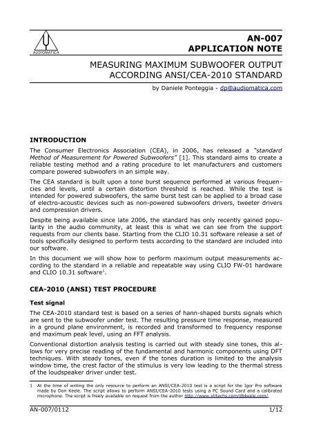
AN-007<br />
APPLICATION NOTE<br />
MEASURING MAXIMUM SUBWOOFER OUTPUT<br />
ACCORDING ANSI/CEA-<strong>2010</strong> STANDARD<br />
by Daniele Ponteggia - dp@audiomatica.com<br />
INTRODUCTION<br />
The Consumer Electronics Association (CEA), in 2006, has released a “standard<br />
Method of Measurement for Powered Subwoofers” [1]. This standard aims to create a<br />
reliable testing method and a rating procedure to let manufacturers and customers<br />
compare powered <strong>subwoofer</strong>s in an simple way.<br />
The CEA standard is built upon a tone burst sequence performed at various frequencies<br />
and levels, until a certain distortion threshold is reached. While the test is<br />
intended for powered <strong>subwoofer</strong>s, the same burst test can be applied to a broad case<br />
of electro-acoustic devices such as non-powered <strong>subwoofer</strong>s drivers, tweeter drivers<br />
and compression drivers.<br />
Despite being available since late 2006, the standard has only recently gained popularity<br />
in the audio community, at least this is what we can see from the support<br />
requests from our clients base. Starting from the CLIO 10.31 software release a set of<br />
tools specifically designed to perform tests <strong>according</strong> to the standard are included into<br />
our software.<br />
In this document we will show how to perform <strong>maximum</strong> <strong>output</strong> measurements <strong>according</strong><br />
to the standard in a reliable and repeatable way using CLIO FW-01 hardware<br />
and CLIO 10.31 software 1 .<br />
CEA-<strong>2010</strong> (ANSI) TEST PROCEDURE<br />
Test signal<br />
The CEA-<strong>2010</strong> standard test is based on a series of hann-shaped bursts signals which<br />
are sent to the <strong>subwoofer</strong> under test. The resulting pressure time response, measured<br />
in a ground plane environment, is recorded and transformed to frequency response<br />
and <strong>maximum</strong> peak level, using an FFT analysis.<br />
Conventional distortion analysis testing is carried out with steady sine tones, this allows<br />
for very precise reading of the fundamental and harmonic components using DFT<br />
techniques. With steady tones, even if the tones duration is limited to the analysis<br />
window time, the crest factor of the stimulus is very low leading to the thermal stress<br />
of the loudspeaker driver under test.<br />
1 At the time of writing the only resource to perform an ANSI/CEA-<strong>2010</strong> test is a script for the Igor Pro software<br />
made by Don Keele. The script allows to perform ANSI/CEA-<strong>2010</strong> tests using a PC Sound Card and a calibrated<br />
microphone. The script is freely available on request from the author http://www.xlrtechs.com/dbkeele.com/.<br />
AN-007/0112 1/12
MEASURING MAXIMUM SUBWOOFER OUTPUT ACCORDING CEA-<strong>2010</strong> (ANSI)<br />
Figure 1: Waveform and magnitude spectrum of a 6.5 cycles 100 Hz<br />
hann-burst<br />
Using a burst signal the crest factor can be freely increased, adjusting the on and off<br />
duration, starting from the 3 dB crest factor of the sine wave.<br />
The test signal used for the CEA-<strong>2010</strong> test is a 6.5 cycles hann-burst signal defined as<br />
the time product between a continuous sinewave and an Hanning window of 6.5 cycles<br />
length [2]:<br />
f (t )={ (2π f t )<br />
(1−cos 0<br />
6.5 ) sin(2π f t ) 0<br />
,for 0⩽t⩽ 6.5<br />
2<br />
f 0<br />
0 ,elsewhere<br />
this signal has the property to be constrained both in the time and in frequency domain.<br />
In figure 1 the waveform and the FFT spectrum of a 6.5 cycles hann-burst at<br />
100 Hz is shown.<br />
The bandwidth of the signal is exactly one third of octave, as requested by the standard.<br />
It must be noted that a third octave bandwidth can be achieved using other time<br />
windows, but the 6.5 cycles hann has the property to minimize the sideband components<br />
of the spectra.<br />
Figure 2 shows the joint time-frequency content (wavelet) of the burst, it is possible<br />
to notice that the signal energy is well constrained both in frequency and in time. The<br />
choice of the off duration of the signal allows for the desired increase of the crest factor.<br />
If we push the off duration to the zero limit, we end up with the crest factor of the<br />
hann-burst sine wave only which is 5.14 dB.<br />
2/12 www.audiomatica.com
MEASURING MAXIMUM SUBWOOFER OUTPUT ACCORDING CEA-<strong>2010</strong> (ANSI)<br />
Typical repetition time for the stimulus is 1 second, but the CEA-<strong>2010</strong> standard does<br />
not give a definition for the repetition time of the burst signal, probably because the<br />
idea is to excite the driver and record with a single shot. As we will see later, using<br />
CLIO it is possible to speed up significantly the test using a repetitive signal while interactively<br />
checking the FFT spectrum of the acquisition against the distortion limits.<br />
Distortion limits<br />
The response of the <strong>subwoofer</strong> under test to the burst signal is measured using a microphone<br />
in ground plane configuration at a distance of at least 1 m. An FFT analysis<br />
is performed on the measured response and the magnitude spectrum of the signal is<br />
calculated.<br />
The spectrum is compared to a distortion limit curve that takes into account the fact<br />
that higher order harmonics are much more audible than low order. The limit curve is<br />
defined by a set of points and it is relative to the burst fundamental frequency f 0 .<br />
Details on the set of points can be found on table 1 of the CEA-<strong>2010</strong> standard, an example<br />
of the limit curve for a fundamental frequency of 100 Hz is shown in figure 3.<br />
Test setup<br />
Figure 2: Joint time-frequency analysis (wavelet) of a 6.5 cycles 100 Hz<br />
hann-burst<br />
The CEA-<strong>2010</strong> standard gives also information on test setup. We will not go here into<br />
deeper details of the standard, we limit ourselves to consider that the measurement<br />
shall be done in ground floor configuration and that rigid surfaces shall be sufficiently<br />
distant so that reflections do not overlap with the driver burst response.<br />
As mentioned before the measurement distance shall be at least 1 m.<br />
3/12 www.audiomatica.com
MEASURING MAXIMUM SUBWOOFER OUTPUT ACCORDING CEA-<strong>2010</strong> (ANSI)<br />
f LOW (Hz) f HIGH (Hz) Limit (dB) Notes<br />
16 1.59 f 0 0 Fundamental<br />
1.59 f 0 2.52 f 0 -10 2 nd harmonic<br />
2.52 f 0 3.78 f 0 -15 3 rd harmonic<br />
3.78 f 0 5.61 f 0 -20 4 th , 5 th harmonic<br />
5.61 f 0 8.50 f 0 -30 6 th , 7 th , 8 th<br />
8.50 f 0 10 k -40 Hi order >9 th<br />
Figure 3: Limit curve for fundamental frequency of 100 Hz and table with<br />
ANSI/CEA-<strong>2010</strong> limits<br />
PERFORMING A CEA-<strong>2010</strong> BURST TEST WITH CLIO<br />
The CLIO 10.31 software release features a new generator stimulus and custom<br />
FFT options that, when used together, allow to perform a CEA-<strong>2010</strong> burst test in a<br />
very simple way.<br />
CLIO CEA-<strong>2010</strong> TONE BURST GENERATOR<br />
A powerful hann-burst tone option has been added to the Signal Generator. Selecting<br />
the CEA Burst option in the generator opens a dialog with the burst options (figure 4).<br />
The generator settings are: burst frequency f 0 in Hz, Number of Cycles and Repetition<br />
Time in ms. While the CEA-<strong>2010</strong> standard requests for a 6.5 cycles burst, we left<br />
the possibility to modify this parameter as it gives the opportunity to use different<br />
“burst-on” durations. For example it is possible to use a 7 cycles burst which is amplitude<br />
symmetrical, instead of 6.5 cycles which is not amplitude symmetrical, while<br />
4/12 www.audiomatica.com
MEASURING MAXIMUM SUBWOOFER OUTPUT ACCORDING CEA-<strong>2010</strong> (ANSI)<br />
Figure 4: CEA Burst generator option and dialog<br />
retaining almost the same 1/3rd octave bandwidth. It is also possible to use longer<br />
bursts, with substantial less bandwidth, to test specific frequencies instead of third octave<br />
bands.<br />
CLIO FFT CEA-<strong>2010</strong> POWER TESTING SCHEME<br />
A check-box “Enable power test” option has been added to the FFT Settings menu under<br />
ANSI/CEA-<strong>2010</strong> (Figure 5). When this option is checked, along with the “Internal<br />
Trigger” option under General options, the CLIO software automatically calculates and<br />
draws the ANSI/CEA-<strong>2010</strong> threshold limit curve. When using this option, the FFT<br />
must be on “dBSPL” units in order to work properly.<br />
The “Enable power test” option applies a time window (see Figure 7) on the acquired<br />
burst response. This helps to window out environmental reflections. Consideration on<br />
room correction factor (RCF) are still applicable as described by the standard.<br />
The “Enable power test” option activates the ANSI/CEA-<strong>2010</strong> peak level detector<br />
(see Figure 8), which is an indicator of the SPL peak level. This level is calculated from<br />
the peak level of the acquired waveform, filtered with a zero-phase bandpass filter<br />
Figure 5: FFT setting for ANSI/CEA-<strong>2010</strong> test<br />
5/12 www.audiomatica.com
MEASURING MAXIMUM SUBWOOFER OUTPUT ACCORDING CEA-<strong>2010</strong> (ANSI)<br />
centered at the test frequency. The CEA-<strong>2010</strong> standard is pretty vague on this point,<br />
as it states:<br />
“The peak SPL of the fundamental ±3 Hz shall then be recorded.<br />
That is, the peak SPL is the highest SPL within the range<br />
bounded by 3 Hz below and 3 Hz above the fundamental.”<br />
Here the terms peak and highest SPL are not sufficiently clear to be understood in a<br />
unambiguous way. Using the bandpass zero-phase filter, the components around the<br />
fundamental are filtered without altering the time envelope of the waveform. Then the<br />
peak value of the pressure in Pa is taken and converted back to a SPL level.<br />
SUBWOOFER MAXIMUM OUTPUT LEVEL PRACTICAL TESTING<br />
We show here an ANSI/CEA-<strong>2010</strong> test of an ACE-bass B2-50 powered <strong>subwoofer</strong>. This<br />
system has two drivers on one side of the cabinet and one port underneath. According<br />
to the standard recommendation we put the microphone at 1 meter off the side of the<br />
box, in order to be equidistant to the box sources (see figure 6).<br />
As measurement distance we chose 1 m only, even if the recommended distance is<br />
2 m. This is due to the fact that the measurement room of our laboratory is not big<br />
enough to avoid reflections. According to the standard a room correction factor should<br />
be calculated and applied but we can skip this step here and go directly to the test<br />
procedure.<br />
The instrument connection set up is very simple: we connect the microphone, an Audiomatica<br />
MIC-02, to the CLIO fw-01 input A and the <strong>subwoofer</strong> input to the CLIO fw-<br />
01 <strong>output</strong> A.<br />
Figure 6: Tested <strong>subwoofer</strong> with microphone in ground plane configuration<br />
6/12 www.audiomatica.com
MEASURING MAXIMUM SUBWOOFER OUTPUT ACCORDING CEA-<strong>2010</strong> (ANSI)<br />
Figure 7: Comparison between burst time response with reflection (upper<br />
graph) and burst time response with time windowing (lower graph)<br />
7/12 www.audiomatica.com
MEASURING MAXIMUM SUBWOOFER OUTPUT ACCORDING CEA-<strong>2010</strong> (ANSI)<br />
Let's start with a preliminary measurement (Figure 7): using the CEA-burst options<br />
we generate a 6.5 cycles 100 Hz burst, with a safe <strong>output</strong> level of -32 dBu. Pressing<br />
F8 key we increment the level in 1 dB steps until we reach a suitable signal-to-noise<br />
ratio.<br />
Then we open the FFT menu and start an FFT analysis on channel A with the internal<br />
trigger option enabled. We chose dBSPL as Y scale unit and 1/12 octave as smoothing<br />
2 . The minimum FFT size should be of 32768 points, since the lowest ANSI/CEA-<br />
<strong>2010</strong> test frequency is 20 Hz, which means, for a 6.5 cycles, a duration of around 325<br />
ms. The result of this FFT analysis is on the upper graph of figure 7, where the effect<br />
of room reflections is clearly visible.<br />
At this point we enable the ANSI/CEA-<strong>2010</strong> option in the FFT menu settings, as previously<br />
shown in figure 5. Looking at the lower graph of figure 7 the effect of the time<br />
windowing is clear. While in this case the room reflections are not completely rejected,<br />
the spectrum is easier to read and not corrupted by reflections.<br />
We are now ready to go on with the ANSI/CEA-<strong>2010</strong> test procedure starting with the<br />
20 Hz test frequency. Again we start with a convenient low <strong>output</strong> level of -24 dBu,<br />
and carefully increment the level in 1 dB steps until the FFT spectra do not reach the<br />
ANSI/CEA-<strong>2010</strong> limit. Once the limit is reached we stop the generator and annotate<br />
the “CEA pressure peak” level reported by the slave meter readout.<br />
Then we repeat the process for the other test frequencies: 25, 31.5, 40, 50, 63 Hz.<br />
Figure 8: CLIO 10 running ANSI/CEA-<strong>2010</strong> test<br />
2 The 1/12 octave smoothing is requested by the ANSI/CEA-<strong>2010</strong> standard.<br />
8/12 www.audiomatica.com
MEASURING MAXIMUM SUBWOOFER OUTPUT ACCORDING CEA-<strong>2010</strong> (ANSI)<br />
Figure 8 shows the complete instrument setup when taking the final 63Hz measurement.<br />
We end up with a data collection table, as suggested by the standard, where the test<br />
frequencies and the peak levels are reported. We added the first column to annotate<br />
the CLIO <strong>output</strong> level.<br />
CLIO <strong>output</strong><br />
level (dBu)<br />
Tone Burst<br />
Frequency<br />
(Hz)<br />
Maximum SPL<br />
(dB)<br />
CEA <strong>2010</strong><br />
Rating<br />
-10 20 99.3<br />
-12 25 95.4<br />
-12 31.5 93.2<br />
96.0<br />
-9 40 103.5<br />
-4 50 113.8<br />
5 63 114.7<br />
110.7<br />
Table 1: Data collection table<br />
Data in the last column is calculated as average of the <strong>maximum</strong> SPL of the 20, 25,<br />
31.5 and 40, 50, 63 Hz frequencies.<br />
The CEA-<strong>2010</strong> rating of this <strong>subwoofer</strong> would be reported as:<br />
Ultra-low bass (20-31.5 Hz): 96.0 dB<br />
Low bass (40-63 Hz): 110.7 dB<br />
With some active <strong>subwoofer</strong>s it may happen that incrementing the input level, the<br />
limit curve is not reached while the <strong>output</strong> level is not increasing. This is due to some<br />
compression mechanism on the <strong>subwoofer</strong> active electronics, in those cases the standard<br />
requires to write down the reached CEA pressure peak level and to proceed to<br />
another frequency band.<br />
CONCLUSIONS<br />
Using CLIO FW-01 and CLIO 10.31 software it is possible to perform <strong>maximum</strong> <strong>output</strong><br />
<strong>subwoofer</strong>s tests <strong>according</strong> to the ANSI/CEA-<strong>2010</strong> standard in an easy and interactive<br />
way. Thanks to the input/<strong>output</strong> and microphone calibration of the CLIO system the<br />
user can concentrate on the practical issues of the ANSI/CEA-<strong>2010</strong> test.<br />
REFERENCES<br />
[1] ANSI/CEA Standard, ”Standard Method of Measurement for Powered Subwoofers<br />
ANSI/CEA-<strong>2010</strong>”, November 2006.<br />
[2] Keele D., “Development of Test Signals for the EIA-426-B Loudspeaker Power Rating<br />
Compact Disc”, presented at the 111th Convention of the Audio Engineering<br />
Society, New York (Sept. 2001).<br />
9/12 www.audiomatica.com
MEASURING MAXIMUM SUBWOOFER OUTPUT ACCORDING CEA-<strong>2010</strong> (ANSI)<br />
Figure 9: ACE-bass B2-50 - ANSI/CEA-<strong>2010</strong> test @ 20 Hz<br />
Figure 10: ACE-bass B2-50 - ANSI/CEA-<strong>2010</strong> test @ 25 Hz<br />
10/12 www.audiomatica.com
MEASURING MAXIMUM SUBWOOFER OUTPUT ACCORDING CEA-<strong>2010</strong> (ANSI)<br />
Figure 11: ACE-bass B2-50 - ANSI/CEA-<strong>2010</strong> test @ 31.5 Hz<br />
Figure 12: ACE-bass B2-50 - ANSI/CEA-<strong>2010</strong> test @ 40 Hz<br />
11/12 www.audiomatica.com
MEASURING MAXIMUM SUBWOOFER OUTPUT ACCORDING CEA-<strong>2010</strong> (ANSI)<br />
Figure 13: ACE-bass B2-50 - ANSI/CEA-<strong>2010</strong> test @ 50 Hz<br />
Figure 14: ACE-bass B2-50 - ANSI/CEA-<strong>2010</strong> test @ 63 Hz<br />
12/12 www.audiomatica.com