You also want an ePaper? Increase the reach of your titles
YUMPU automatically turns print PDFs into web optimized ePapers that Google loves.
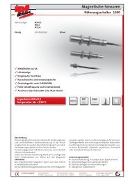
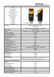
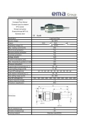
<strong>SBCR</strong>01<br />
Mono-beam safety control unit (category 2)<br />
for accident prevention in dangerous areas<br />
● System composed of a control unit and a pair of optic<br />
sensors – M18 (SK) or M30 (TK)<br />
● Control unit mountable on DIN rail:<br />
The same control unit can use 5 different pairs of sensors<br />
M18 and M30 for increased money and space saving: optic<br />
protection (4 models) or surface protection with STP<br />
accessory (1 model)<br />
● Control circuit with intrinsic safety system<br />
● The <strong>SBCR</strong>01 safety system is certified as a category 2<br />
protection device and complies with the pr EN50100<br />
standard<br />
● 2 safety relays in the output circuit<br />
● Free/engaged area LED indicator<br />
● Response time 35ms (typical), 140 ms (max.)<br />
Ordering system<br />
serie<br />
S B C R 0 1 - A<br />
operating voltage<br />
control unit for single through beam<br />
<strong>SBCR</strong>01<br />
A<br />
24VAC<br />
D<br />
48VAC<br />
H<br />
115VAC<br />
Z<br />
230VAC<br />
S<br />
24VDC<br />
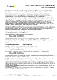
Dimensions<br />
21 2<br />
3<br />
20 19 18 17 16 15 14 13 12 11<br />
1. emitter wiring connections<br />
70<br />
0V<br />
+9V<br />
Check +<br />
EMITTER<br />
Check -<br />
TEST<br />
<strong>SBCR</strong>01<br />
ENGAGED<br />
AREA<br />
+9V<br />
0V<br />
RECEIVER<br />
FREE<br />
AREA<br />
OUT<br />
4<br />
5<br />
2. TEST contact for checking external actuators<br />
9<br />
SUPPLY<br />
N (-) L1 (+)<br />
F<br />
MM<br />
CHECK OUTPUT<br />
OPER. OUTPUT<br />
1 2 3 4 5 6 7 8 9 10<br />
3. receiver wiring connections<br />
8<br />
7 6<br />
100<br />
4. red LED (engaged area indicator)<br />
5. green LED (clear area indicator)<br />
6. OPERATING OUTPUT<br />
7. CHECK OUTPUT<br />
110<br />
8. power supply (24-48-110-220VAC; 24VDC)<br />
10<br />
10<br />
18<br />
9. power supply fuse (inside)<br />
10. fastening holes 85x60mm
<strong>SBCR</strong>01<br />
Specifications<br />
Model <strong>SBCR</strong>O1-A <strong>SBCR</strong>O1-D <strong>SBCR</strong>O1-H <strong>SBCR</strong>O1-Z <strong>SBCR</strong>O1-S<br />
Type AC AC AC AC DC<br />
Operating voltage 24VAC 48VAC 115VAC 230VAC 24VDC<br />
Tolerance<br />
Line frequency<br />
Max. absorption<br />
Available functions<br />
Safety output<br />
Max. switching voltage<br />
Max. switching current<br />
Contact isolation<br />
Contact life<br />
Response time<br />
LED indicators<br />
Inputs<br />
Protection degree<br />
Temperature range<br />
Storage temperature<br />
Ambient humidity<br />
Housing material<br />
Weight (approx.)<br />
+ 10% - 15%<br />
50 - 60 Hz<br />
6VA<br />
Start/Restart, EDM (to be realized with external contactors)<br />
forced contact relay: 1 contact NO, 1 contact NC<br />
250VAC<br />
6A (in use), 20A (switching)<br />
250VAC<br />
1x10 5 (electrical), 1x10 7 (mechanical)<br />
35ms (typical), 140ms (max.)<br />
green (free area), red (engaged area)<br />
Test<br />
IEC IP20<br />
0…+50°C<br />
-25°…+75°C<br />
35…95%<br />
ABS<br />
440g<br />
±15%<br />
-<br />
250mA<br />
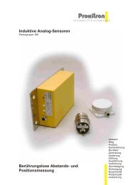
Wiring diagrams<br />
L (+)<br />
emitter<br />
receiver<br />
Emergency<br />
BL/3<br />
BN/1<br />
BK/4<br />
WH/2<br />
BK/4<br />
BN/1<br />
BL/3<br />
20 19 17 18 11 13 12 8 6<br />
Start<br />
Test<br />
09Vcheck<br />
out 9V 0<br />
2<br />
1<br />
L (+)<br />
N (-)<br />
Power supply<br />
+<br />
-<br />
Relay<br />
C<br />
operating<br />
output<br />
check<br />
output<br />
3<br />
MM<br />
D<br />
k1<br />
test<br />
input<br />
10 4 15<br />
16<br />
k3<br />
k1<br />
k3<br />
k2<br />
k1<br />
k3<br />
k2<br />
C<br />
K1<br />
k2<br />
K2 K3<br />
R<br />
N (-)<br />
K1, K2, K3:<br />
External<br />
contactors<br />
R, C:<br />
Arc suppression<br />
unit<br />
To the line<br />
K2<br />
K2<br />
K2<br />
K3<br />
K3<br />
K3<br />
K1<br />
K1<br />
K1<br />
To the motor which starts-up<br />
the dangerous movement<br />
19
<strong>SBCR</strong>01<br />
The following sensors can be connected to the <strong>SBCR</strong>01 safety control unit:<br />
SK serie: SK1 models M18 through-beam optical protection guard up to 4m<br />
SK serie: SK2 models M18 through-beam optical protection guard up to 8m<br />
SK serie: SK4 models M18 through-beam optical protection guard up to 4m (visible light)<br />
SK serie: SK3 models M18 through-beam with STP accessories surface protection guard up to 3m<br />
TK serie: TK1 model M30 through-beam optical protection guard up to 50m<br />
Description<br />
The <strong>SBCR</strong>01 safety system’s purpose is to protect the access area<br />
of machines with dangerous moving parts, which are ever more<br />
frequently used in productive processes.<br />
The <strong>SBCR</strong>01 safety system is made up of a control unit and a pair<br />
of cylindrical sensors, emitter and receiver, which can be those in<br />
the SK (M18) or in the TK (M30) range.<br />
The safety sensors emit a beam of red or infrared light which<br />
locks out the dangerous movement the moment it is interrupted<br />
by an opaque object.<br />
The <strong>SBCR</strong>01 system represents an inescapable and therefore<br />
extremely safe system with an extremely quick response time.<br />
The protection capacity in terms of the size of the protected<br />
zone, target to be detected and safety distance, depends on the<br />
intrinsic characteristics of the safety light curtain, in accordance<br />
with the pr EN50100-1 and pr EN50100-2 regulations, and on the<br />
application conditions in accordance with the regulation EN294<br />
and EN999.<br />
The <strong>SBCR</strong>01 system is capable of detecting an individual failure<br />
by carrying out a periodic test cycle, which can be activated<br />
through the relative test input.<br />
If a failure is detected, the system activates the safety conditions<br />
by locking the dangerous movement.<br />
The <strong>SBCR</strong>01 control unit is equipped with two forced contact<br />
relay outputs: an operating output and a check output. The operating<br />
output is used to control the dangerous movement (NO<br />
contact), while the check output is used to activate a supplementary<br />
control for the operating output (NC contact).<br />
The availability of two supplementary outputs allows an “alternate<br />
control” to be carried out, which prevents systematic failures.<br />
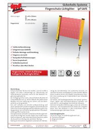
SK3 through-beam<br />
(with sensitivity<br />
adjustment)<br />
Aluminium support<br />
STP accessory<br />
Soft compressible<br />
rubber<br />
The receiver is equipped with a sensitivity adjuster which can be<br />
used to determine the level of the pressure which sets-off the<br />
activation; the adjustment allows the activation threshold to be<br />
set from a few millimetres up to a maximum of 13mm, which correspond<br />
to the inside diameter of the STP accessory.<br />
It is preferable for the operator to have an activation threshold<br />
of a few millimetres, as this reduces the possibility of eventual<br />
panic situations.<br />
However, maintaining this threshold cannot be guaranteed in the<br />
event of a failure. As a consequence, the system must be designed<br />
so that it is safe (the operator shall not get hurt) even if<br />
the activation threshold, for whatever reason, reaches the maximum<br />
level.<br />
dangerous<br />
machine<br />
Besides optical protections through sensors SK1, SK2, SK3 and<br />
TK1, the <strong>SBCR</strong>01 control unit can also perform pressure protections<br />
on a length of up to 3m, using SK3 sensors and the STP<br />
accessory.<br />
Fitting the system as indicated in the figure, the safety light curtain<br />
beam is directed towards the inside of the soft, compressible<br />
rubber accessory; pressure on the rubber part will interrupt<br />
the inside beam and cause the system to switch to the safety<br />
mode.<br />
surface<br />
pressure<br />
protection<br />
beam not interrupted<br />
by the processed material<br />
material being processed<br />
which does not interfere<br />
with the beam<br />
beam interrupted<br />
(pressure on the rubber guide)<br />
free guarded area<br />
normal operation<br />
engaged guarded area<br />
locked operation<br />
20
<strong>SBCR</strong>01<br />
The STP accessory end parts, into which the sensors are<br />
fitted, cannot be part of the sensitive field – this must be kept<br />
in mind at the beginning of the project.<br />
If it is necessary to obtain an area which is more sensitive to<br />
pressure, there is a STOK accessory which has an adjustable<br />
mechanical shutter.<br />
Applications<br />
The optical-electronic <strong>SBCR</strong>01 safety system can be<br />
specifically used as a safety component in the following application<br />
fields:<br />
Perimeter protections<br />
these are required to protect the operator from voluntary or accidental<br />
intrusion into a danger area where there are fixed or mobile<br />
manufacturing machines.<br />
Some examples can be:<br />
Packaging machinery in general;<br />
Conveyor and assembly lines;<br />
Automatic warehouses<br />
Robotized areas;<br />
Palletizers and unloaders;<br />
Wrapping machines;<br />
Machines for the ceramic industry.<br />
Elimination of possible interference<br />
between fixed machines and movable machinery or units inside<br />
the equipped production facilities, in compliance with the rules<br />
for the realisation of anti-collision systems or “give-way” systems<br />
for material handling.<br />
Some examples can be:<br />
material handling areas;<br />
hoisting machines;<br />
work places with overhead travelling cranes or lifting cranes.<br />
Surface protection<br />
this is required to protect the operator from getting his hands<br />
crushed or when it is necessary to work in close contact with the<br />
machine.<br />
Some examples can be:<br />
rollers;<br />
machines for hide processing;<br />
sacking and packaging machines;<br />
automatic gates and doors.<br />
21