
You also want an ePaper? Increase the reach of your titles
YUMPU automatically turns print PDFs into web optimized ePapers that Google loves.
How to Service<br />
<strong>French</strong> <strong>Horn</strong> <strong>Rotors</strong><br />
by Jeff Smith<br />
With a few simple, affordable supplies and this<br />
step-by-step guidance, musicians and music directors<br />
can easily learn to service rotor valves. This can be of<br />
great benefit in both emergency situations and as a matter<br />
of regular maintenance. While there are many points of<br />
service that can be attended to without great investment<br />
or advanced skill, there are still many areas of repair<br />
(beyond the scope of this article) that must be referred to<br />
professional technicians.<br />
Cleaning<br />
and Lubrication<br />
As a musical and mechanical necessity, rotor valves have<br />
a very tight clearance between the rotor and valve casing<br />
and at the bearings. Because of this, any deposits on any<br />
part may cause the valve to lock in place or freeze up. This is<br />
most likely to be experienced after the instrument has been<br />
unused for some time.<br />
Playing the instrument daily tends to keep minerals and<br />
lubricants from hardening into deposits. This is particularly<br />
true if the musician lubricates the rotors frequently. The<br />
lubrication helps the valve shed any contaminants, and fills<br />
the space that would otherwise attract water-born minerals,<br />
which create deposits.<br />
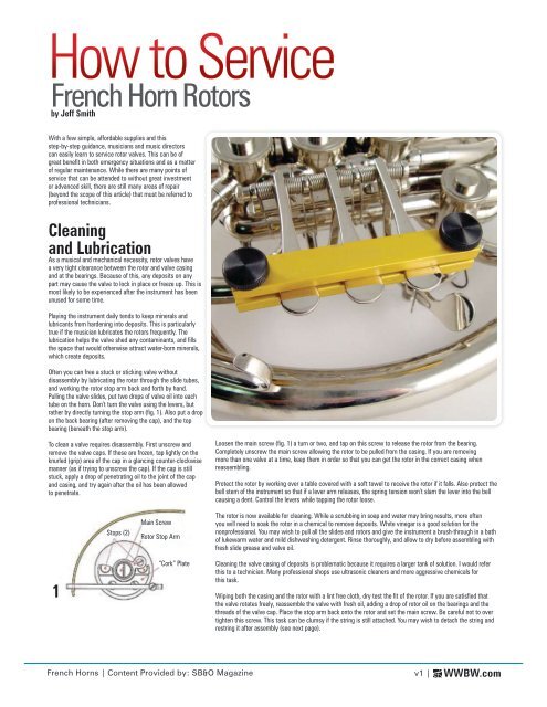
Often you can free a stuck or sticking valve without<br />
disassembly by lubricating the rotor through the slide tubes,<br />
and working the rotor stop arm back and forth by hand.<br />
Pulling the valve slides, put two drops of valve oil into each<br />
tube on the horn. Don’t turn the valve using the levers, but<br />
rather by directly turning the stop arm (fig. 1). Also put a drop<br />
on the back bearing (after removing the cap), and the top<br />
bearing (beneath the stop arm).<br />
To clean a valve requires disassembly. First unscrew and<br />
remove the valve caps. If these are frozen, tap lightly on the<br />
knurled (grip) area of the cap in a glancing counter-clockwise<br />
manner (as if trying to unscrew the cap). If the cap is still<br />
stuck, apply a drop of penetrating oil to the joint of the cap<br />
and casing, and try again after the oil has been allowed<br />
to penetrate.<br />
Loosen the main screw (fig. 1) a turn or two, and tap on this screw to release the rotor from the bearing.<br />
Completely unscrew the main screw allowing the rotor to be pulled from the casing. If you are removing<br />
more than one valve at a time, keep them in order so that you can get the rotor in the correct casing when<br />
reassembling.<br />
Protect the rotor by working over a table covered with a soft towel to receive the rotor if it falls. Also protect the<br />
bell stem of the instrument so that if a lever arm releases, the spring tension won’t slam the lever into the bell<br />
causing a dent. Control the levers while tapping the rotor loose.<br />
Stops (2)<br />
Main Screw<br />
Rotor Stop Arm<br />
The rotor is now available for cleaning. While a scrubbing in soap and water may bring results, more often<br />
you will need to soak the rotor in a chemical to remove deposits. White vinegar is a good solution for the<br />
nonprofessional. You may wish to pull all the slides and rotors and give the instrument a brush-through in a bath<br />
of lukewarm water and mild dishwashing detergent. Rinse thoroughly, and allow to dry before assembling with<br />
fresh slide grease and valve oil.<br />
1<br />
“Cork” Plate<br />
Cleaning the valve casing of deposits is problematic because it requires a larger tank of solution. I would refer<br />
this to a technician. Many professional shops use ultrasonic cleaners and more aggressive chemicals for<br />
this task.<br />
Wiping both the casing and the rotor with a lint free cloth, dry test the fit of the rotor. If you are satisfied that<br />
the valve rotates freely, reassemble the valve with fresh oil, adding a drop of rotor oil on the bearings and the<br />
threads of the valve cap. Place the stop arm back onto the rotor and set the main screw. Be careful not to over<br />
tighten this screw. This task can be clumsy if the string is still attached. You may wish to detach the string and<br />
restring it after assembly (see next page).<br />
<strong>French</strong> <strong>Horn</strong>s | Content Provided by: SB&O Magazine<br />
v1 |<br />
WWBW.com
How to Service<br />
<strong>French</strong> <strong>Horn</strong> <strong>Rotors</strong><br />
by Jeff Smith<br />
Continued<br />
Adjusting Rotor<br />
Port Alignment<br />
In order for the instrument to play its best,<br />
it is necessary that the rotor valve ports<br />
align correctly with the tubing to which they<br />
direct the airflow to (fig. 7). Taking the valve<br />
cap off the rotor, you will see corresponding<br />
marks in both the rotor shaft and in the back<br />
bearing. You will also notice a small notch on<br />
the outer edge of the back bearing (fig. 9).<br />
1. Align the notch in the back bearing with<br />
the corresponding notch in the valve casing.<br />
This bearing is gently pressed into place. If<br />
it is not located correctly, loosen the stop<br />
arm main screw (fig. 1) a couple turns. Tap<br />
on this screw to release the back bearing,<br />
rotate the bearing to its home position, and<br />
tap it back into place. Reset the<br />
main screw.<br />
Note: when securing the bearing, it is best<br />
to use a plastic tube (or a dowel with a<br />
center hole), which fits over the center<br />
of the bearing. Tap on this tube to equally<br />
distribute the pressure applied by the<br />
hammer.<br />
2. Moving the rotor stop arm all the way<br />
in each direction, observe the position of<br />
the mark in the rotor in relation to the mark<br />
in the bearing. These must align perfectly<br />
when at each stop<br />
(fig. 10 & 11).<br />
3. This alignment is adjusted by changing<br />
the size of the rotor stops. The rotor stops<br />
are often neoprene, sometimes cork. The<br />
JLS kit includes neoprene. Use this to<br />
replace stops that are missing or too small<br />
to be adjusted. If the stop is too large, it can<br />
be cut back with a razor blade.<br />
4. While it may be possible to insert<br />
new stops while all parts are assembled,<br />
it sometimes is necessary to remove the<br />
cork plate from the casing (making a bigger<br />
job). The stop material often needs to be<br />
squeezed with pliers or stretched to fit into<br />
the plate. The material will then expand to<br />
fit securely in the cork plate. If you remove<br />
the cork plate, you can hold one end of the<br />
neoprene in a vice, which easily allows<br />
you to stretch the material and insert it into<br />
place. Trim the excess on each side of the<br />
plate with a razor blade.<br />
7<br />
8<br />
9<br />
10<br />
11<br />
Notch<br />
Rotor Valve<br />
Schematic<br />
Back Bearing<br />
Rotor<br />
Shaft<br />
Adjusted<br />
Misadjusted<br />
Restringing Guide<br />
These instructions include the use of the<br />
JLS #206058 Valve Restringing Kit.<br />
1. Set the Stringing Jig in place over the<br />
lever touch pieces as shown. This will keep<br />
all levers on plane with each other. (Note:<br />
if all valves are being restrung, you will<br />
determine the touch piece height when you<br />
secure the first screw in step 6).<br />
2. Loosen the rotor stop and the lever string<br />
screws and remove the old string. Don’t<br />
loosen the screws more than enough to<br />
remove the old string (we don’t want to<br />
lose them).<br />
3. Cut a new piece of string about<br />
8 inches long.<br />
4. Tie a knot in one end. This will act as<br />
a stopper to keep the string from pulling<br />
through, so make the knot larger than the<br />
hole in the lever arm.<br />
5. Thread the string through the hole as<br />
shown in fig. 1. Tip: if you cut the string at<br />
an angle, you can pass it through the hole<br />
easier. Use a sharp razor blade to make<br />
this cut.<br />
6. Holding the rotor arm in the position<br />
shown, wrap the string as in fig.2, making<br />
sure that the string goes under the screw.<br />
Continue wrapping as shown in fig. 3.<br />
Secure the screw (don’t over tighten).<br />
7. Continue with the string as in fig. 4, then<br />
take it through the hole (fig. 5), and wrap it<br />
under the screw. Secure this screw.<br />
8. When at rest, the arm of the lever will<br />
usually be set at an elevated angle to the<br />
rotor so that when the lever is pressed<br />
the arm won’t be too low (which can<br />
cause binding and noise) (fig. 6). It may be<br />
necessary to re-align the lever arm to the<br />
touch piece. The alignment is performed<br />
by holding the touch piece and bending the<br />
end of the lever either up or down. The lever<br />
ends should all be on plane with each other<br />
just as the touch pieces were.<br />
9. To add a professional touch, clip the ends<br />
of the strings so that they are the same<br />
length. To allow for possible adjustment<br />
later, leave the unknotted end at least<br />
3/4" long.<br />
1<br />
2<br />
3<br />
4<br />
5<br />
6<br />
Stops (2)<br />
Main Screw<br />
Rotor Stop Arm<br />
“Cork”<br />
Plate<br />
Hold<br />
Over<br />
Lever Slightly<br />
Higher Than<br />
Stop Arm<br />
<strong>French</strong> <strong>Horn</strong>s | Content Provided by: SB&O Magazine<br />
v1 |<br />
WWBW.com