AMX-140FX/ AMX-140 - Alto, Music Passion Design
AMX-140FX/ AMX-140 - Alto, Music Passion Design
AMX-140FX/ AMX-140 - Alto, Music Passion Design

You also want an ePaper? Increase the reach of your titles
YUMPU automatically turns print PDFs into web optimized ePapers that Google loves.
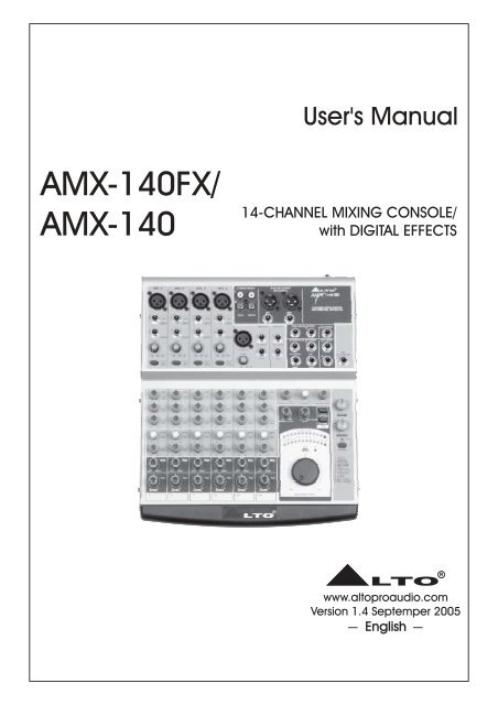
User's Manual<br />
<strong>AMX</strong>-<strong><strong>140</strong>FX</strong>/<br />
<strong>AMX</strong>-<strong>140</strong><br />
14-CHANNEL MIXING CONSOLE/<br />
with DIGITAL EFFECTS<br />
LTO R<br />
www.altoproaudio.com<br />
Version 1.4 Septemper 2005<br />
English
SAFETY RELATED SYMBOLS<br />
ON:<br />
CAUTION<br />
RISK OF ELECTRIC SHOCK<br />
DO NOT OPEN<br />
This symbol, wherever used, alerts you to the presence<br />
of un-insulated and dangerous voltages within<br />
the product enclosure. These are voltages that<br />
may be sufficient to constitute the risk of electric<br />
shock or death.<br />
This symbol, wherever used, alerts you to important<br />
operating and maintenance instructions.<br />
Please read.<br />
Protective Ground Terminal<br />
AC mains (Alternating Current)<br />
Hazardous Live Terminal<br />
Denotes the product is turned on.<br />
OFF: Denotes the product is turned off.<br />
WARNING<br />
Describes precautions that should be observed to<br />
prevent the possibility of death or injury to the user.<br />
CAUTION<br />
Describes precautions that should be observed to<br />
prevent damage to the product.<br />
Disposing of this product should not be<br />
placed in municipal waste and should be<br />
Separate collection.<br />
WARNING<br />
Power Supply<br />
Ensure that the mains source voltage (AC outlet)<br />
matches the voltage rating of the product. Failure<br />
to do so could result in damage to the product and<br />
possibly the user.<br />
Unplug the product before electrical storms occur<br />
and when unused for long periods of time to reduce<br />
the risk of electric shock or fire.<br />
External Connection<br />
Always use proper ready-made insulated mains<br />
cabling (power cord). Failure to do so could result<br />
in shock/death or fire. If in doubt, seek advice from<br />
a registered electrician.<br />
Do Not Remove Any Covers<br />
Within the product are areas where high voltages<br />
may present. To reduce the risk of electric shock do<br />
not remove any covers unless the AC mains power<br />
cord is removed.<br />
Covers should be removed by qualified service<br />
personnel only.<br />
No user serviceable parts inside.<br />
Fuse<br />
To prevent fire and damage to the product, use only<br />
the recommended fuse type as indicated in this<br />
manual. Do not short-circuit the fuse holder. Before<br />
replacing the fuse, make sure that the product is<br />
OFF and disconnected from the AC outlet.<br />
Protective Ground<br />
Before turning the product ON, make sure that it is<br />
connected to Ground. This is to prevent the risk of<br />
electric shock.<br />
Never cut internal or external Ground wires. Likewise,<br />
never remove Ground wiring from the Protective<br />
Ground Terminal.<br />
Operating Conditions<br />
Always install in accordance with the manufacturer's<br />
instructions.<br />
To avoid the risk of electric shock and damage, do<br />
not subject this product to any liquid/rain or moisture.<br />
Do not use this product when in close proximity to<br />
water.<br />
Do not install this product near any direct heat source.<br />
Do not block areas of ventilation. Failure to do so<br />
could result in fire.<br />
Keep product away from naked flames.<br />
IMPORTANT SAFETY INSTRUCTIONS<br />
Read these instructions<br />
Follow all instructions<br />
Keep these instructions. Do not discard.<br />
Heed all warnings.<br />
Only use attachments/accessories specified by the<br />
manufacturer.<br />
Power Cord and Plug<br />
Do not tamper with the power cord or plug. These are<br />
designed for your safety.<br />
Do not remove Ground connections!<br />
If the plug does not fit your AC outlet seek advice from<br />
a qualified electrician.<br />
Protect the power cord and plug from any physical<br />
stress to avoid risk of electric shock.<br />
Do not place heavy objects on the power cord. This<br />
could cause electric shock or fire.<br />
Cleaning<br />
When required, either blow off dust from the product<br />
or use a dry cloth.<br />
Do not use any solvents such as Benzol or Alcohol.<br />
For safety, keep product clean and free from dust.<br />
Servicing<br />
Refer all servicing to qualified service personnel only.<br />
Do not perform any servicing other than those instructions<br />
contained within the User's Manual.<br />
1
PREFACE<br />
Dear Customer:<br />
Thank you for choosing the LTO <strong>AMX</strong>-<strong>140</strong> 14-Channel Mixing Console (<strong>AMX</strong>-<strong><strong>140</strong>FX</strong> 14-Channel Mixing Console<br />
with Digital Effects), which is the result of our LTO AUDIO TEAM's endeavours.<br />
For the<br />
LTO AUDIO TEAM, music and audio are more than a profession, it is a passion and an obsession!<br />
We have, in fact, been designing professional audio products for a number of years in cooperation with many of the<br />
world's major brands.<br />
The LTO line represents unparalleled analogue and digital products made by musicians, for musicians. With our<br />
design centres in Italy, the Netherlands, and the United Kingdom we provide you with world-class designs, while our<br />
software development teams continue to develop an impressive range of audio specific algorithms.<br />
By purchasing our LTO products you become the most important member of our LTO AUDIO TEAM. We would<br />
like to share with you our passion for what we design and invite you to make suggestions, which will aid us in developing<br />
future products for you. We guarantee you our commitment for quality, continual research and development,<br />
and of course the best prices.<br />
The LTO <strong>AMX</strong>-<strong>140</strong>(FX) mixing console is equipped with 4 mono input channels (these are provided with ultra low noise<br />
microphone pre-amplifiers and phantom power at +48 Volt), 4 stereo input channels, 4 stereo aux returns and 2 TK IN.<br />
So, in total you have 14 input channels on your <strong>AMX</strong>-<strong>140</strong>(FX). It is specifically designed for professional application.<br />
Seeing is believing, let's meet the LTO <strong>AMX</strong>-<strong>140</strong>(FX).<br />
We would like to thank all the people who made the LTO <strong>AMX</strong>-<strong>140</strong>(FX) 14-Channel Mixing Console possible, especially<br />
to our designers and LTO staff. It is their passion for music and professional audio that has made it possible<br />
for us to offer you, our most important team member, our continued support.<br />
Thank you very much<br />
LTO AUDIO TEAM<br />
2
TABLE OF CONTENTS<br />
1.INTRODUCTION...................................................................................................................................................4<br />
2.FEATURES...........................................................................................................................................................5<br />
3.READY TO START?...............................................................................................................................................6<br />
4.CONTROL ELEMENTS.......................................................................................................................................7<br />
4.1 MONO MIC/LINE Channels .........................................................................................................................9<br />
4.2 INPUT LEVEL Setting ..................................................................................................................................9<br />
4.3 MONO Channel INSERT ..............................................................................................................................9<br />
4.4 LOW CUT Switch ........................................................................................................................................9<br />
4.5 STEREO Inputs ..........................................................................................................................................10<br />
4.6 3 BANDS EQUALIZER Controls ................................................................................................................10<br />
4.7 AUX SENDS Controls ...............................................................................................................................10<br />
4.8 PAN/BAL Control .......................................................................................................................................11<br />
4.9 PEAK LED ..................................................................................................................................................11<br />
4.10 LEVEL Control ...........................................................................................................................................11<br />
4.11 MAIN MIX LEVEL Dial ...............................................................................................................................11<br />
4.12 OUTPUT LEVEL LED Display ....................................................................................................................11<br />
4.13 POWER LED .............................................................................................................................................11<br />
4.14 PHANTOM LED .......................................................................................................................................11<br />
4.15 TAPE Switches .........................................................................................................................................11<br />
4.16 2TK IN Control ...........................................................................................................................................12<br />
4.17 PHONES/CTRL ROOM Control ...............................................................................................................12<br />
4.18 AUX RETURN Controls ............................................................................................................................12<br />
4.19 AUX SENDS Connectors ........................................................................................................................12<br />
4.20 STEREO AUX RETURNS Connectors .....................................................................................................12<br />
4.21 PHONES ...................................................................................................................................................12<br />
4.22 CTRL ROOM OUTPUT Connectors..........................................................................................................12<br />
4.23 24 BIT DIGITAL EFFECTS (For <strong>AMX</strong>-<strong><strong>140</strong>FX</strong> Model) ................................................................................13<br />
4.24 2TK IN/OUT Connectors .............................................................................................................................13<br />
4.25 MAIN MIX OUTPUT Connectors ...............................................................................................................14<br />
4.26 REAR PANEL Description ........................................................................................................................14<br />
5.INSTALLATION AND CONNECTION.....................................................................................................................15<br />
6.FOR THE EXPERTS WHO WANT TO KNOW MORE..........................................................................................18<br />
7.PRESET LIST.........................................................................................................................................................19<br />
8.BLOCK DIAGRAMS.............................................................................................................................................20<br />
9.TECHNICAL SPECIFICATION..............................................................................................................................21<br />
10.WARRANTY.........................................................................................................................................................23<br />
3
1. INTRODUCTION<br />
Thank you very much for expressing your confidence in LTO products by purchasing LTO <strong>AMX</strong>-<strong>140</strong>(FX) mixing console.<br />
The <strong>AMX</strong>-<strong>140</strong>(FX) is a professional compact mixer. You will get the smooth, accurate more natural and open sound from<br />
this apparatus, and it is really ideal for small gigs, recording and fixed PA installations.<br />
The <strong>AMX</strong>-<strong>140</strong>(FX) mixing console is packed with some key features that can not be found in other consoles of its size:<br />
4 mono (these are provided with ultra low noise microphone pre-amplifiers and phantom power at +48 Volt) and 4<br />
stereo input channels, and each of them is provided with a 3 bands graphic equalizer for HI, MID and LOW controls;<br />
highly accurate 12-segment bar graph meters and 2-Track inputs assignable to main mix, control room / headphone<br />
outputs etc.. Besides, the 24 bit effects processor with 256 effects (16 presets 16 variations) is equipped specifically<br />
for <strong>AMX</strong>-<strong><strong>140</strong>FX</strong>.<br />
Your <strong>AMX</strong>-<strong>140</strong>(FX) is very easy to operate but we advise you to go through each section of this manual carefully.<br />
In this way you will get the best out of your <strong>AMX</strong>-<strong>140</strong>(FX).<br />
4
2. FEATURES<br />
The <strong>AMX</strong>-<strong>140</strong>(FX) mixing console is designed for professional application. It will provide the following features:<br />
The common features:<br />
5 MIC input channels with gold plated XLRs and balanced LINE input<br />
4 stereo input channels with balanced TRS jacks<br />
Ultra-low noise discrete MIC pre-amps with +48V Phantom power<br />
Extremely high headroom offering more dynamic range<br />
Balanced inputs for highest signal integrity<br />
Warm, natural 3-band EQ on each channel<br />
Switch-able Low-cut filter on each mono channel<br />
Peak LED on each channel<br />
AUX send 1/2 per channel for external effects and monitoring<br />
4 AUX returns for additional functionality<br />
Control room and headphone outputs<br />
2-Track inputs assignable to main mix, control room / headphone outputs<br />
Highly accurate 12-segment bar graph meters<br />
Inserts on MIC channels<br />
Additionally, the <strong>AMX</strong>-<strong><strong>140</strong>FX</strong> is also equipped with following features:<br />
24 bit digital effects processor<br />
256 effects (16 presets 16 variations)<br />
Effect on/off by means of MUTE switch or a footswitch connected to the DFX FOOTSWITCH<br />
5
3. READY TO START?<br />
3.1 Please check the AC voltage available in your country before connecting your <strong>AMX</strong>-<strong>140</strong>(FX) to the AC socket.<br />
3.2 Be sure that the main power switch is turned off before connecting the mixer to the AC socket. Also, you should<br />
make sure that all Input and output controls are turned down. This will avoid damages to your speakers and avoid<br />
excessive noise.<br />
3.3 Before turning on the <strong>AMX</strong>-<strong>140</strong>(FX) you shall connect it to a power amplifier and turn-on the mixer BEFORE the power<br />
amplifier. Once you have finished your working session you shall turn the mixer off AFTER the power amplifier.<br />
3.4 Before disconnecting the <strong>AMX</strong>-<strong>140</strong>(FX) always turn-off the power switch.<br />
3.5 Do not use solvents to clean your <strong>AMX</strong>-<strong>140</strong>(FX). A dry and clean cloth will be OK.<br />
6
8<br />
8<br />
8<br />
8<br />
8<br />
8<br />
8<br />
8<br />
8<br />
8<br />
8<br />
8<br />
8<br />
8<br />
8<br />
8<br />
8<br />
8<br />
8<br />
8<br />
4. CONTROL ELEMENTS<br />
<strong>AMX</strong>-<strong><strong>140</strong>FX</strong><br />
MIC 1 MIC 2 MIC 3 MIC 4<br />
2<br />
J.T.<br />
3<br />
1<br />
2<br />
J.T.<br />
3<br />
1<br />
2<br />
J.T.<br />
3<br />
1<br />
2<br />
J.T.<br />
3<br />
1<br />
2-TRACK IN/OUT<br />
L<br />
R<br />
MAIN MIX OUTPUT<br />
(BAL/UNBAL)<br />
AM<br />
LTO R<br />
-<strong>140</strong> FX<br />
14-CHANNEL MIXING CONSOLE<br />
WITH DIGITAL EFFECTS<br />
BAL OR<br />
UNBAL<br />
BAL OR<br />
UNBAL<br />
BAL OR<br />
UNBAL<br />
BAL OR<br />
UNBAL<br />
TAPE IN<br />
TAPE OUT<br />
LEFT<br />
RIGHT<br />
LINE IN 1<br />
LINE IN 2 LINE IN 3 LINE IN 4<br />
LINE IN 5/6 LINE IN 7/8<br />
L<br />
CTRL ROOM OUTPUT<br />
R<br />
PHONES<br />
INSERT INSERT INSERT INSERT<br />
TRIM TRIM TRIM TRIM<br />
2<br />
J.T.<br />
3<br />
1<br />
LEFT(MONO)<br />
LEFT (MONO)<br />
STEREO AUX RETURNS<br />
1 2<br />
AUX SENDS<br />
1<br />
+15dB -30dB LINE<br />
0dB 44dB MIC<br />
LOW CUT<br />
75Hz<br />
18dB/Oct<br />
+15dB -30dB LINE<br />
0dB 44dB MIC<br />
LOW CUT<br />
75Hz<br />
18dB/Oct<br />
+15dB -30dB LINE<br />
0dB 44dB MIC<br />
LOW CUT<br />
75Hz<br />
18dB/Oct<br />
+15dB -30dB LINE<br />
0dB 44dB MIC<br />
LOW CUT<br />
75Hz<br />
18dB/Oct<br />
MIC (MONO)<br />
TRIM<br />
0dB 44dB MIC<br />
RIGHT<br />
RIGHT<br />
LEFT(MONO)<br />
RIGHT<br />
LEFT(MONO)<br />
RIGHT<br />
2<br />
DSP<br />
FOOTSWITCH<br />
EQ<br />
EQ<br />
EQ<br />
EQ<br />
EQ<br />
EQ<br />
0<br />
0<br />
0<br />
1<br />
-15 +15<br />
-12 +12<br />
-15 +15<br />
- +15<br />
HI<br />
12kHz<br />
MID<br />
2.5kHz<br />
LOW<br />
80Hz<br />
AUX<br />
PRE<br />
HI<br />
12kHz<br />
-15 +15<br />
MID<br />
2.5kHz<br />
-12 +12<br />
LOW<br />
80Hz<br />
-15 +15<br />
1 AUX<br />
- +15<br />
PRE<br />
HI<br />
12kHz<br />
-15 +15<br />
MID<br />
2.5kHz<br />
-12 +12<br />
LOW<br />
80Hz<br />
-15 +15<br />
1 AUX<br />
- +15<br />
PRE<br />
HI<br />
12kHz<br />
-15 +15<br />
MID<br />
2.5kHz<br />
-12 +12<br />
LOW<br />
80Hz<br />
-15 +15<br />
1 AUX<br />
- +15<br />
PRE<br />
HI<br />
12kHz<br />
-15 +15<br />
MID<br />
2.5kHz<br />
-12 +12<br />
LOW<br />
80Hz<br />
-15 +15<br />
1 AUX<br />
- +15<br />
PRE<br />
HI<br />
12kHz<br />
-15 +15<br />
MID<br />
2.5kl<br />
-12 +12<br />
LOW<br />
80Hz<br />
-15 +15<br />
1 AUX<br />
- +15<br />
PRE<br />
- +15<br />
AUX2/DFX TO AUX 1<br />
8<br />
- MAX<br />
PHONES / CTRL ROOM<br />
-10<br />
-20<br />
-30<br />
- MAX<br />
2TK IN<br />
-7 -4 -2<br />
- +15<br />
AUX RTN 1<br />
8<br />
OUTPUT LEVEL<br />
0<br />
2<br />
4<br />
- +15<br />
AUX RTN 2 (DFX)<br />
8<br />
2TK TO<br />
CTRL ROOM<br />
2TK TO MIX<br />
TAPE<br />
L<br />
7<br />
10<br />
CLIP<br />
15 16<br />
14<br />
13<br />
1<br />
2<br />
3<br />
4<br />
5<br />
12<br />
6<br />
11 7<br />
10 9 8<br />
PRESETS<br />
15 16<br />
14<br />
13<br />
1<br />
2<br />
3<br />
4<br />
5<br />
12<br />
6<br />
11 7<br />
10 9 8<br />
VARIATIONS<br />
PEAK<br />
2 /<br />
D POST<br />
FX (PRE)<br />
POST<br />
(PRE)<br />
POST<br />
(PRE)<br />
POST<br />
(PRE)<br />
POST<br />
(PRE)<br />
POST<br />
(PRE)<br />
2 /<br />
D<br />
FX<br />
2 /DFX<br />
2 /DFX<br />
2 /DFX<br />
2 /DFX<br />
14. REV. + DELAY<br />
PWR<br />
PH<br />
R<br />
DFX MUTE<br />
- +15<br />
PAN<br />
LEFT RIGHT<br />
PEAK<br />
- +15<br />
LEFT<br />
RIGHT<br />
PAN<br />
- +15<br />
LEFT<br />
RIGHT<br />
PAN<br />
- +15<br />
LEFT<br />
RIGHT<br />
PAN<br />
- +15<br />
LEFT<br />
RIGHT<br />
BAL<br />
- +15<br />
LEFT<br />
RIGHT<br />
BAL<br />
PEAK PEAK PEAK PEAK PEAK<br />
1. VOCAL 1<br />
2. VOCAL 2<br />
3. LARGE HALL<br />
4. SMALL HALL<br />
5. LARGE ROOM<br />
6. SMALL ROOM<br />
7. PLATE<br />
8. TAPE REVERB<br />
9. SPRING REVERB<br />
10. MONO DELAY<br />
11. STEREO DELAY<br />
12. FLANGER<br />
13. CHORUS<br />
15. REV. + FLANGER<br />
16. REV. + CHORUS<br />
- +15<br />
LEVEL<br />
1<br />
- +15<br />
LEVEL<br />
- +15<br />
LEVEL<br />
- +15<br />
LEVEL<br />
- +15<br />
LEVEL<br />
2 3 4 5/6 7/8<br />
- +15<br />
LEVEL<br />
-<br />
8<br />
MAIN MIX LEVEL<br />
+15<br />
7
8<br />
8<br />
8<br />
8<br />
8<br />
8<br />
8<br />
8<br />
8<br />
8<br />
8<br />
8<br />
8<br />
8<br />
8<br />
8<br />
8<br />
8<br />
8<br />
8<br />
8<br />
8<br />
<strong>AMX</strong>-<strong>140</strong><br />
MIC 1 MIC 2 MIC 3 MIC 4<br />
2<br />
J.T.<br />
3<br />
1<br />
2<br />
J.T.<br />
3<br />
1<br />
2<br />
J.T.<br />
3<br />
1<br />
2<br />
J.T.<br />
3<br />
1<br />
2-TRACK IN/OUT<br />
L<br />
R<br />
MAIN MIX OUTPUT<br />
(BAL/UNBAL)<br />
AM<br />
LTO R<br />
-<strong>140</strong><br />
14-CHANNEL MIXING CONSOLE<br />
BAL OR<br />
UNBAL<br />
BAL OR<br />
UNBAL<br />
BAL OR<br />
UNBAL<br />
BAL OR<br />
UNBAL<br />
TAPE IN<br />
TAPE OUT<br />
LEFT<br />
RIGHT<br />
LINE IN 1<br />
LINE IN 2 LINE IN 3 LINE IN 4<br />
LINE IN 5/6 LINE IN 7/8<br />
L<br />
CTRL ROOM OUTPUT<br />
R<br />
PHONES<br />
INSERT<br />
INSERT INSERT INSERT<br />
TRIM TRIM TRIM TRIM<br />
2<br />
J.T.<br />
3<br />
1<br />
LEFT(MONO)<br />
LEFT (MONO)<br />
STEREO AUX RETURNS<br />
1 2<br />
AUX SENDS<br />
1<br />
MIC (MONO)<br />
+15dB -30dB LINE<br />
0dB 44dB MIC<br />
LOW CUT<br />
75Hz<br />
18dB/Oct<br />
+15dB -30dB LINE<br />
0dB 44dB MIC<br />
LOW CUT<br />
75Hz<br />
18dB/Oct<br />
+15dB -30dB LINE<br />
0dB 44dB MIC<br />
LOW CUT<br />
75Hz<br />
18dB/Oct<br />
+15dB -30dB LINE<br />
0dB 44dB MIC<br />
LOW CUT<br />
75Hz<br />
18dB/Oct<br />
TRIM<br />
0dB 44dB MIC<br />
RIGHT<br />
RIGHT<br />
LEFT(MONO)<br />
RIGHT<br />
LEFT(MONO)<br />
RIGHT<br />
2<br />
EQ<br />
EQ<br />
EQ<br />
EQ<br />
EQ<br />
EQ<br />
0<br />
0<br />
0<br />
HI<br />
12kHz<br />
HI<br />
12kHz<br />
HI<br />
12kHz<br />
HI<br />
12kHz<br />
HI<br />
12kHz<br />
HI<br />
12kHz<br />
-15 +15<br />
-15 +15<br />
-15 +15<br />
-15 +15<br />
-15 +15<br />
-15 +15<br />
- +15<br />
AUX2 TO AUX 1<br />
- +15<br />
- +15<br />
AUX RTN 1 AUX RTN 2<br />
MID<br />
2.5kHz<br />
MID<br />
2.5kHz<br />
MID<br />
2.5kHz<br />
MID<br />
2.5kHz<br />
MID<br />
2.5kHz<br />
MID<br />
2.5kl<br />
-12 +12<br />
-12 +12<br />
-12 +12<br />
-12 +12<br />
-12 +12<br />
-12 +12<br />
LOW<br />
80Hz<br />
LOW<br />
80Hz<br />
LOW<br />
80Hz<br />
LOW<br />
80Hz<br />
LOW<br />
80Hz<br />
LOW<br />
80Hz<br />
- MAX<br />
PHONES / CTRL ROOM<br />
2TK TO MIX<br />
2TK TO<br />
CTRL ROOM<br />
-15 +15<br />
1 AUX<br />
-15 +15<br />
1 AUX<br />
-15 +15<br />
1 AUX<br />
-15 +15<br />
1 AUX<br />
-15 +15<br />
1 AUX<br />
-15 +15<br />
1 AUX<br />
OUTPUT LEVEL<br />
2<br />
PRE<br />
- +15<br />
POST<br />
(PRE)<br />
- +15<br />
PRE<br />
PRE<br />
PRE<br />
PRE<br />
PRE<br />
- +15<br />
- +15<br />
- +15<br />
2 2 2 2 2<br />
- +15<br />
POST<br />
POST<br />
POST<br />
POST<br />
POST<br />
(PRE)<br />
(PRE)<br />
(PRE)<br />
(PRE)<br />
(PRE)<br />
-10<br />
-20<br />
-30<br />
-7 -4<br />
-2<br />
0<br />
PWR<br />
2<br />
4<br />
L<br />
7<br />
10<br />
CLIP<br />
R<br />
PH<br />
- +15<br />
- +15<br />
- +15<br />
- +15<br />
- +15<br />
- +15<br />
PAN<br />
PAN<br />
PAN<br />
PAN<br />
BAL<br />
BAL<br />
LEFT<br />
RIGHT<br />
LEFT<br />
RIGHT<br />
LEFT<br />
RIGHT<br />
LEFT<br />
RIGHT<br />
LEFT<br />
RIGHT<br />
LEFT<br />
RIGHT<br />
PEAK<br />
PEAK PEAK PEAK PEAK PEAK<br />
- +15<br />
LEVEL<br />
1<br />
- +15<br />
LEVEL<br />
- +15<br />
LEVEL<br />
- +15<br />
LEVEL<br />
- +15<br />
LEVEL<br />
2 3 4 5/6 7/8<br />
- +15<br />
LEVEL<br />
-<br />
8<br />
MAIN MIX LEVEL<br />
+15<br />
8
4.1 MONO MIC/LINE Channels<br />
These are channel 1 through channel 4. You can connect balanced, low impedance<br />
microphones to the XLR socket. On the 1/4" phone jack you can connect<br />
either a microphone or a line level instrument. You shall never connect an unbalanced<br />
microphone to the XLR socket if you do not want to damage both the<br />
microphone and the mixer.<br />
48 Volt phantom power<br />
2<br />
It is available only to the XLR Mic sockets. Never plug in a microphone when<br />
phantom power is already on. Before turning phantom power on, make sure<br />
that all faders are all the way down. In this way you will protect your stage<br />
monitors and main loudspeakers.<br />
1<br />
MIC 1<br />
2<br />
TRIM<br />
J.T.<br />
3<br />
1<br />
BAL OR<br />
UNBAL<br />
LINE IN 1<br />
INSERT<br />
1<br />
4<br />
4.2 INPUT LEVEL Setting<br />
This control is provided with 2 different indication rings: One is<br />
for the microphone and the other for the line levels. When you<br />
use a microphone you shall read the OUTSIDE ring (0~44 dB),<br />
when you use a line level instrument you shall read the INSIDE<br />
ring (+15~-30 dB). For optimum operation you shall set this control<br />
in a way that the peak LED will blink also occasionally in order to<br />
avoid distortion on the input channel.<br />
3<br />
+15dB -30dB LINE<br />
0dB 44dB MIC<br />
LOW CUT<br />
75Hz<br />
18dB/Oct<br />
3<br />
5<br />
4.3 MONO Channel INSERT 4<br />
Insert points are provided for each mono MIC channel, which can<br />
allow you patch external signal processing devices into signal<br />
path. When you insert a TRS jack in the insert socket, the signal<br />
will be taken out after the input gain control (Trim), sent to an external<br />
processor such as a compressor-limiter, and returned into<br />
the channel strip immediately before the EQ section. Of course,<br />
the jacks used must be stereo (Tip Send/Ring Return).<br />
ON<br />
OFF<br />
POWER<br />
PHANTOM<br />
2<br />
4.4 LOW CUT Switch<br />
5<br />
By pressing this button you will activate a 75 Hz low frequency filter with a slope of 18 dB per octave. You can use<br />
this facility to reduce the hum noise infected by the mains power supply, or the stage rumble while using a microphone.<br />
9
4.5 STEREO Inputs<br />
6<br />
LINE IN 5/6 LINE IN 7/8<br />
These are Channel 5 through 8. They are organised<br />
in stereo pair and provided with 1/4" TRS sockets.<br />
2<br />
J.T.<br />
1<br />
If you connect only the left jack, the input will operate<br />
in mono mode.<br />
3<br />
LEFT(MONO)<br />
LEFT (MONO)<br />
6<br />
MIC (MONO)<br />
TRIM<br />
RIGHT<br />
RIGHT<br />
0dB<br />
44dB MIC<br />
4.6 3 BANDS EQUALIZER Controls<br />
A 3-band equalizer is provided for all input channels with a wide<br />
range of frequency adjustment.<br />
4.6.1 HI<br />
7<br />
This is the Treble control. You can use it to get rid of high frequency<br />
noises or to boost the sound of cymbals or the high harmonics of<br />
the human voice. The gain range goes from -15dB to +15dB with<br />
a center frequency of 12 kHz.<br />
-15 +15<br />
EQ<br />
HI<br />
12kHz<br />
MID<br />
2.5kHz<br />
7<br />
8<br />
-12 +12<br />
4.6.2 MID<br />
This is the Midrange control. It can affect most fundamental frequencies<br />
of all musical instruments and human voice. An attentive<br />
use of this control will give you any very wide panorama of sound<br />
effects. The gain range goes from -12dB to +12dB and the center<br />
frequency is 2.5 kHz.<br />
4.6.3 LOW<br />
8<br />
9<br />
This is the Bass control. Boost male voice or kickdrum and bass<br />
guitar. Your system will sound much bigger than what it is. The gain<br />
range goes from -15dB to +15dB and the center frequency is 80 Hz.<br />
1<br />
-15 +15<br />
LOW<br />
80Hz<br />
AUX<br />
PRE<br />
- +15<br />
2<br />
/<br />
D POST<br />
FX (PRE)<br />
8<br />
- +15<br />
8<br />
PAN<br />
9<br />
10<br />
11<br />
4.7 AUX SEND Controls<br />
10<br />
These two controls are used to adjust the level of the signal sent to<br />
AUX buses, and their adjustable range goes from - to +15dB.<br />
AUX1 is configured as PRE-FADER, so, generally, it can be used<br />
for monitor application. While AUX2 is configured as POST-FADER,<br />
therefore, most of the times, it will be used for effects and processors<br />
input, however, you can also changed it to PRE-FADER configuration<br />
according to the specific application. (For more detail, please see<br />
chapter 6.)<br />
LEFT<br />
RIGHT<br />
- +15<br />
LEVEL<br />
8<br />
1<br />
PEAK<br />
12<br />
13<br />
10
4.25 MAIN MIX OUTPUT Connectors 34<br />
The stereo output is supplied both with XLR and 1/4" TRS sockets,<br />
which is used to send the audio signal to an amplifier.<br />
Through the main mix level control, you can adjust the output level<br />
from - to +15dB.<br />
MAIN MIX OUTPUT<br />
(BAL/UNBAL)<br />
LEFT<br />
RIGHT<br />
34<br />
4.26 REAR PANEL Description<br />
ON<br />
OFF<br />
18VAC~<br />
POWER PHANTOM<br />
RATED POWER CONSUMPTION: 25W<br />
CAUTION<br />
RISK OF ELECTRIC SHOCK<br />
DO NOT OPEN<br />
WARNING: SHOCK HAZARD - DO NOT OPEN<br />
AVIS: RISQUE DE CHOC ELECTRIQUE - NE PAS OUVRIR<br />
MODEL<br />
SERIAL<br />
35 2 36<br />
- POWER ON/OFF Switch 35<br />
This switch is used to turn the main power ON and OFF.<br />
- PHANTOM ON/OFF Switch<br />
2<br />
This switch will apply +48 Volt Phantom Power only to the 5 XLR microphone inputs. Never connect microphones<br />
when the phantom power is on already.<br />
- AC INPUT Connector<br />
This connector is used to connect the supplied AC Adapter.<br />
36<br />
14
4.16 2TK IN Control 20<br />
This control is used to adjust the level of 2TK IN signal, which can be varied from -<br />
to MAX.<br />
4.17 PHONES/CTRL ROOM Control 21<br />
This control sets the amount of signal sent to the control room and headphone.<br />
4.18 AUX RETURN Controls<br />
22<br />
As implied in the name, the auxiliary returns are used to 'return' the<br />
signal from the external effects or processors to the main mix, but,<br />
most of the times, it can also be worked as the additional stereo line<br />
inputs.<br />
0<br />
0<br />
0<br />
In this typical compact unit:<br />
AUX RETURN1 is configured to be assigned to the main mix bus<br />
permanently, for mono application, only use the left input jack.<br />
But for AUX RETURN2, excluding assigning the returned signal to<br />
main mix bus, it can also to AUX1 bus, and in this case, adjust AUX2/<br />
DFX TO AUX1 knob 23 to control the input level.<br />
- +15<br />
AUX2/DFX TO AUX 1<br />
8<br />
23<br />
- +15<br />
AUX RTN 1<br />
8<br />
22<br />
- +15<br />
AUX RTN 2 (DFX)<br />
8<br />
In <strong>AMX</strong>-<strong><strong>140</strong>FX</strong> model, AUX RETURN2 (DFX) is connected rightly<br />
with the output of the internal digital effects, but, this signal flow will<br />
be broken, if you have any external signal inserted from these two<br />
jacks.<br />
4.19 AUX SENDS Connectors<br />
These 1/4" sockets are used to send out the signal from the AUX<br />
bus to external devices such effects.<br />
24<br />
27<br />
26<br />
L<br />
CTRL ROOM OUTPUT<br />
R<br />
PHONES<br />
4.20 STEREO AUX RETURNS Connectors<br />
Use these stereo 1/4" sockets to return the sound of an effect<br />
unit to the main mix. You can also use them as the extra auxiliary<br />
inputs.<br />
25<br />
STEREO AUX RETURNS<br />
1 2<br />
AUX SENDS<br />
1<br />
LEFT(MONO)<br />
LEFT(MONO)<br />
2<br />
4.21 PHONES<br />
26<br />
This socket will send out the mix signal to a pair of headphones.<br />
RIGHT<br />
RIGHT<br />
4.22 CTRL ROOM OUTPUT Connectors<br />
27<br />
These 1/4" sockets are used to send the control room signal to<br />
the studio monitor speakers or a second set of PA.<br />
25<br />
24<br />
12
4.23 24 BIT DIGITAL EFFECTS (For <strong>AMX</strong>-<strong><strong>140</strong>FX</strong> Model)<br />
- PRESETS Control 28<br />
Adjust this knob to select the right effect you wish to perform.<br />
There are total 16 options for you: several kinds of reverb, mono<br />
and stereo delay, effects with modulation, and versatile two-effect<br />
combination.<br />
DSP<br />
FOOTSWITCH<br />
- VARIATIONS Control 29<br />
Since you have selected the preferable effect, the next step, please<br />
go with the fine consideration, there are also total 16 variations for<br />
each preset. Each variation may be managed by several different<br />
factors.<br />
- MUTE Switch 30<br />
This switch is used to activate/deactivate the effect facility.<br />
Sometimes, you can also use the DFX FOOTSWITCH for convenient<br />
operation.<br />
- PEAK LED 31<br />
This LED lights up when the input signal is too strong.<br />
In case of the digital effect module being muted, this LED also<br />
lights up.<br />
15 16<br />
14<br />
13<br />
1<br />
2<br />
3<br />
12<br />
6<br />
11 7<br />
10 9 8<br />
PRESETS<br />
15 16<br />
14<br />
13<br />
1<br />
2<br />
3<br />
DFX MUTE<br />
4<br />
5<br />
4<br />
5<br />
12<br />
6<br />
11 7<br />
10 9 8<br />
VARIATIONS<br />
PEAK<br />
32<br />
28<br />
29<br />
31<br />
30<br />
- DSP FOOTSWITCH 32<br />
This 1/4" phone jack can be used to connect an external footswitch<br />
to turn on/off the onboard effect module.<br />
1. VOCAL 1<br />
2. VOCAL 2<br />
3. LARGE HALL<br />
4. SMALL HALL<br />
5. LARGE ROOM<br />
6. SMALL ROOM<br />
7. PLATE<br />
8. TAPE REVERB<br />
9. SPRING REVERB<br />
10. MONO DELAY<br />
11. STEREO DELAY<br />
12. FLANGER<br />
13. CHORUS<br />
14. REV. + DELAY<br />
15. REV. + FLANGER<br />
16. REV. + CHORUS<br />
4.24 2TK IN/OUT Connectors<br />
33<br />
-TAPEIN<br />
Use the tape input if you wish to listen to your mix from a taper<br />
recorder or DAT. You can assign the signal coming from the taper<br />
recorder either to a pair of studio monitor using the control room<br />
assignment on the front panel or you can also send the signal<br />
directly to the main mix.<br />
L<br />
R<br />
2-TRACK IN/OUT<br />
33<br />
-TAPEOUT<br />
These RCA jacks will route the main mix into a tape recorder.<br />
TAPE IN<br />
TAPE OUT<br />
13
In the <strong>AMX</strong>-<strong><strong>140</strong>FX</strong> model, excluding sending out directly to the external effect or processor equipment, the AUX SEND2<br />
will also be sent to the internal onboard effect module.<br />
4.8 PAN/BAL Control<br />
11<br />
Abbreviation of PANORAMA control for mono channels, for the stereo channels, always says, BALANCE control.<br />
You can adjust the stereo image of the signal via this control. Keep this control in center position and your signal<br />
will be positioned in the middle of stage. Turn this control fully counterclockwise and the signal will be present only<br />
on the left speaker and vice-versa.<br />
4.9 PEAK LED 12<br />
Inside your <strong>AMX</strong>-<strong>140</strong>(FX) the audio signal is monitored in several different stages and then sent to the PEAK LED.<br />
When this LED blinks, it warns you that you are reaching signal saturation and possible distortion. The PEAK LED will<br />
blink with a level that is 6dB before actual clipping.<br />
4.10 LEVEL Control 13<br />
This control will adjust the overall level of this channel and set the amount of signal sent to the main output.<br />
4.11 MAIN MIX LEVEL Dial 14<br />
This control sets the amount of signal sent either<br />
to the main out socket or to the tape output.<br />
21<br />
20<br />
18<br />
4.12 OUTPUT LEVEL LED Display<br />
15<br />
2TK TO<br />
CTRL ROOM<br />
This stereo 12 segments LED meter will indicate<br />
the level of the overall output signal.<br />
- MAX<br />
PHONES / CTRL ROOM<br />
8<br />
-<br />
8<br />
MAX<br />
2TK IN<br />
2TK TO MIX<br />
TAPE<br />
19<br />
OUTPUT LEVEL<br />
4.13 POWER LED 16<br />
This LED indicates when the power is on in your<br />
<strong>AMX</strong>-<strong>140</strong>(FX).<br />
-20<br />
-30<br />
-10<br />
-7<br />
-4<br />
-2<br />
0<br />
PWR<br />
2<br />
4<br />
PH<br />
7<br />
10<br />
CLIP<br />
16 17<br />
L<br />
R<br />
15<br />
4.14 PHANTOM LED<br />
17<br />
This LED indicates when the phantom power is<br />
switched on.<br />
4.15 TAPE Switches<br />
- 2TK TO CTRL ROOM<br />
18<br />
Engaging this button to route the 2 TRACK IN signal<br />
into the control room output.<br />
-<br />
8<br />
MAIN MIX LEVEL<br />
+15<br />
- 2TK TO MIX<br />
19<br />
Engaging this button to route the 2 TRACK IN signal<br />
into the main output.<br />
14<br />
11
5. INSTALLATION AND CONNECTION<br />
Ok, you have got to this point you are now in the position to successfully operate your <strong>AMX</strong>-<strong>140</strong>(FX). However, we<br />
advise you to read carefully the following section to be the real master of your own mix. Not paying attention enough<br />
to the Input signal level, to the routing of the signal and the assignment of the signal will result in unwanted distortion,<br />
a corrupted signal or no sound at all. So you should follow this procedure for every single channel:<br />
Turn down all Input and output gain controls.<br />
Connect phantom powered microphones before switching on the +48Volt phantom power switch.<br />
If you have a power amplifier connected to your <strong>AMX</strong>-<strong>140</strong>(FX) set the level of the amplifier at no more than 75%.<br />
Now, set the CONTROL ROOM/PHONES level at no more than 50%. In this way you will be able to hear later<br />
you are doing connecting a pair of headphones or a pair of powered studio monitor speakers.<br />
Position HI, MID and LOW EQ controls on the middle.<br />
Position panoramic (PAN) control on the center.<br />
With a headphone or studio monitor speakers connected apply a Line Level input signal so that the PEAK LED does<br />
not light up.<br />
At this point increase the input gain so that the PEAK LED will blink occasionally. In this way you will maintain good<br />
headroom and ideal dynamic range.<br />
Now connect a microphone and ask the singer to sing loud into the microphone. Turn slowly the Gain Control clockwise<br />
and have the PEAK LED blink only occasionally.<br />
Now repeat the same sequence for all input channels. The main LED Meter could move up into the red section.<br />
this case you can adjust the overall output level through the MAIN MIX control.<br />
what<br />
In<br />
15
2 1<br />
3<br />
3<br />
3<br />
1 2<br />
3<br />
1 2<br />
3<br />
1 2<br />
3<br />
1 2<br />
3<br />
1 2<br />
3<br />
5.1 Audio Connection<br />
Both XLR and 1/4 " TRS connectors are available on the unit. In this way you can interface the unit in several<br />
different ways without experiencing any noise or signal loss. You can use the unit with single instruments using<br />
The mixer's main insert or on "in-line" between a mixing console's output and a power amplifier.<br />
- Wiring Configuration<br />
Either the 1/4" TRS phone jack or XLR connector can be wired in balanced and unbalanced modes, which will<br />
be determined by the actual application status, please wire your system as the following wiring examples:<br />
For 1/4" Phone jack<br />
+<br />
+<br />
Tip<br />
Sleeve<br />
Ring<br />
Tip<br />
Sleeve<br />
Ring<br />
+<br />
-<br />
TRS Type Unbalanced<br />
Tip<br />
Sleeve<br />
TS Type Unbalanced<br />
TRS Type Balanced<br />
For XLR connector<br />
Pin2 (+)<br />
Pin3 (-)<br />
(Linked to Pin1 manually, )<br />
Pin3 (-)<br />
Pin2 (+)<br />
Pin1 ( )<br />
Pin1 ( )<br />
XLR Type Unbalanced XLR Type Balanced<br />
- In-line Connection<br />
For these applications the unit provides 1/4" TRS and XLR connectors to easily interface with most<br />
professional audio devices. Follow the configuration examples below for your particular connection.<br />
Balanced<br />
TIP RING SLEEVE<br />
SLEEVE RING TIP<br />
Tip<br />
Ring<br />
Sleeve<br />
Tip<br />
Ring<br />
Sleeve<br />
1<br />
2<br />
3<br />
1<br />
2<br />
3<br />
TIP RING SLEEVE<br />
Tip<br />
Ring<br />
Sleeve<br />
1<br />
2<br />
3<br />
Unbalanced<br />
TIP RING SLEEVE<br />
Tip<br />
Ring<br />
Sleeve<br />
1<br />
2<br />
3<br />
TIP SLEEVE<br />
Tip<br />
Sleeve<br />
1<br />
2<br />
3<br />
2 1<br />
1<br />
2<br />
3<br />
Centre<br />
Screen<br />
Tip<br />
Tip<br />
TIP SLEEVE<br />
SLEEVE TIP<br />
Sleeve<br />
Sleeve<br />
TIP RING SLEEVE<br />
SLEEVE RING TIP<br />
Tip<br />
Ring<br />
Sleeve<br />
Tip<br />
Ring<br />
Sleeve<br />
TIP SLEEVE<br />
Tip<br />
Sleeve<br />
Centre<br />
Screen<br />
Tip<br />
Ring<br />
Centre<br />
TIP RING SLEEVE<br />
Sleeve<br />
Screen<br />
2 1<br />
1<br />
2<br />
3<br />
1<br />
2<br />
3<br />
16
1 2<br />
3<br />
- Insert Points Connection<br />
If you are connecting to a mixing console's main inserts, you may have a single TRS jack for Send and<br />
Return, in this case, use an insert "Y" cable that configured like the examples below.<br />
1/4" TRS insert Insert Leads<br />
Send<br />
Return<br />
TIP RING SLEEVE<br />
SLEEVE TIP<br />
SLEEVE RING TIP<br />
Tip<br />
Ring<br />
Sleeve<br />
Tip (Send)<br />
Sleeve<br />
Tip (Return)<br />
Sleeve<br />
1<br />
TIP RING SLEEVE<br />
2 1<br />
3<br />
Tip<br />
Ring<br />
Sleeve<br />
2 (Send)<br />
3<br />
1<br />
2 (Return)<br />
Ring<br />
Tip<br />
Sleeve<br />
TIP RING SLEEVE<br />
Tip<br />
Ring<br />
Sleeve<br />
3<br />
Centre (Send)<br />
Screen<br />
Centre (Return)<br />
Screen<br />
17
6. FOR THE EXPERTS WHO WANT TO KNOW MORE<br />
As we have told you previously in this manual, the AUX SEND2 control both on mono and on stereo channels is factory<br />
wired as POST-FADER. If you have some skill in electronic components soldering you can modify this setting and have<br />
all your AUX SENDS configured as PRE-FADER.<br />
AUX<br />
AUX<br />
(PRE)<br />
POST<br />
Disconnect<br />
the POST route<br />
(PRE)<br />
POST<br />
Solder the PRE route<br />
Before<br />
After<br />
Modification on mono and stereo channels<br />
18
7. PRESET LIST (For <strong>AMX</strong>-<strong><strong>140</strong>FX</strong> Model)<br />
No. Preset Description<br />
Controllable parameter<br />
Parameter Variable range<br />
1<br />
VOCAL 1 Simulate a room with small delay time. Decay time<br />
Pre-delay<br />
0.8~1.1s<br />
0~79ms<br />
2<br />
VOCAL 2<br />
Simulate a small space with slight decay time.<br />
Decay time<br />
0.8~2.5s<br />
Pre-delay<br />
0~79ms<br />
3<br />
LARGE HALL<br />
Simulate a large acoustic space of the sound.<br />
Decay time<br />
3.6~5.4s<br />
Pre-delay<br />
23~55ms<br />
4<br />
SMALL HALL<br />
Simulate a small acoustic space of the sound.<br />
Decay time<br />
1.0~2.9s<br />
Pre-delay<br />
20~45ms<br />
5<br />
LARGE ROOM<br />
Simulate a studio room with many early reflections.<br />
Decay time<br />
Pre-delay<br />
2.9~4.5s<br />
23~55ms<br />
6<br />
SMALL ROOM<br />
Simulate a bright studio room.<br />
Decay time<br />
0.7~2.1s<br />
Pre-delay<br />
20~45ms<br />
7<br />
PLATE<br />
Simulate the transducers sound like classic bright<br />
Decay time<br />
0.6~6.1s<br />
vocal plate.<br />
Pre-delay<br />
10ms<br />
8<br />
TAPE REVERB<br />
Simulate a record head and multiple playback heads<br />
Decay time<br />
1.3~5.4s<br />
at intervals along the tape.<br />
Pre-delay<br />
0~84ms<br />
9<br />
SPRING REVERB<br />
Simulate the analog transducers' springs lightly<br />
Decay time<br />
1.3~5.4s<br />
stretched sound.<br />
Pre-delay<br />
0~35ms<br />
10<br />
MONO DELAY<br />
Reproduce the sound input on the outputafter a<br />
Period<br />
60~650ms<br />
lapse of time.<br />
11<br />
STEREO DELAY<br />
Recreate the input sound on the stereo output with<br />
Period<br />
210~400ms<br />
different time.<br />
Feedback<br />
37~73%<br />
12<br />
FLANGER<br />
Simulate to play with another person carryingout<br />
Rate<br />
0.16~2.79Hz<br />
sam e the notes on the same instrument<br />
13<br />
CHORUS<br />
Recreate the illusion of more than one instrument<br />
Rate<br />
0.5~5Hz<br />
from a single instrument sound<br />
14<br />
REV.+DELAY<br />
Delay with room effect<br />
Delay period<br />
Rev. decay time<br />
211~375ms<br />
1.0~2.9s<br />
15<br />
REV.+FLANGER<br />
Stereo chorus and large room reverb<br />
Flanger Rate<br />
Rev. decay time<br />
0.16~2.52Hz<br />
1.5~2.9s<br />
16<br />
REV.+CHORUS<br />
Simulate the sound effect achieved by rotating horn<br />
speakers and a bass cylinder<br />
Chorus rate<br />
Rev. decay time<br />
0.5~4.74Hz<br />
1.5~2.9s<br />
19
S<br />
-<br />
-<br />
S<br />
S<br />
S<br />
-<br />
-<br />
-<br />
-<br />
-<br />
S<br />
S<br />
S<br />
8. BLOCK DIAGRAMS<br />
D<br />
C<br />
B<br />
A<br />
8<br />
2<br />
3<br />
4<br />
5<br />
6<br />
7<br />
1<br />
LEFT-BUS<br />
RIGHT-BUS<br />
AUX-1<br />
AUX-2<br />
EFX SEND<br />
MONO INPUT CHANNELS ( 1-4 )<br />
PHANTOM<br />
POWER<br />
+48V<br />
GAIN<br />
LO MID HI<br />
LEVEL<br />
R<br />
T<br />
AUX SEND<br />
MIC IN<br />
2<br />
3<br />
1<br />
80 2.5K 12K<br />
3-BAND EQ<br />
3<br />
1<br />
LO CUT<br />
2<br />
R<br />
T<br />
AUX SEND1<br />
+<br />
LINE IN<br />
MIC GAIN:0~60dB<br />
LINE IN TRIM:+15dB~-45dB<br />
3c<br />
4d<br />
2b<br />
1a<br />
5e<br />
R<br />
RN<br />
TN<br />
T<br />
S<br />
75Hz<br />
HI PASS<br />
SG/OL<br />
LO MID HI<br />
POST<br />
1 2<br />
PRE<br />
1 2<br />
AUX1<br />
AUX2<br />
MAIN MIX<br />
LEVEL<br />
R<br />
T<br />
2<br />
3<br />
1<br />
AUX SEND2<br />
MAIN OUT<br />
STEREO INPUT CHANNELS (5-8)<br />
LEFT(MONO)<br />
RIGHT<br />
PHANTOM<br />
POWER<br />
+48V<br />
3c<br />
4d<br />
2b<br />
1a<br />
5e<br />
3c<br />
4d<br />
2b<br />
1a<br />
5e<br />
PAN<br />
LEVEL<br />
BALANCE<br />
R<br />
RN<br />
-<br />
TN<br />
S<br />
R<br />
RN<br />
TN<br />
S<br />
AUX2<br />
TN<br />
T<br />
T<br />
+<br />
+<br />
GAIN<br />
80 2.5K 12K<br />
3-BAND EQ<br />
80<br />
2.5K 12K<br />
EQ<br />
2TK TO MIX<br />
1<br />
3<br />
1<br />
3<br />
2<br />
2<br />
2TK IN<br />
LEVEL<br />
TAPE IN<br />
R<br />
T<br />
2<br />
3<br />
1<br />
2-TRACK<br />
MAIN MIX LEFT<br />
MAIN MIX RIGHT<br />
TAPE OUT<br />
LEFT<br />
AUX1<br />
2TK TO CTRL ROOM<br />
1<br />
RIGHT<br />
2<br />
3<br />
+<br />
MIC5 IN<br />
2<br />
3<br />
1<br />
SG/OL<br />
STEREO AUX RETURN 1<br />
3c<br />
4d<br />
2b<br />
1a<br />
5e<br />
R<br />
RN<br />
TN<br />
T<br />
S<br />
CHANNEL 5,6 ONLY<br />
+<br />
AUX RETURN1<br />
1<br />
2<br />
3<br />
PHONES OUTPUT<br />
R<br />
T<br />
PHONES<br />
LEFT(MONO)<br />
RIGHT<br />
STEREO AUX RETURN 2<br />
LEFT<br />
3c<br />
4d<br />
2b<br />
1a<br />
5e<br />
3c<br />
4d<br />
2b<br />
1a<br />
5e<br />
R<br />
RN<br />
TN<br />
T<br />
S<br />
R<br />
RN<br />
TN<br />
T<br />
S<br />
+<br />
+<br />
AUX RETURN2<br />
CONTROL ROOM<br />
&PHONES<br />
LEFT METER<br />
CONTROL ROOM OUTPUT<br />
R<br />
T<br />
R<br />
T<br />
LEFT<br />
RIGHT<br />
3c<br />
4d<br />
2b<br />
1a<br />
R<br />
RN<br />
T<br />
+<br />
RIGHT METER<br />
RIGHT<br />
5e<br />
S<br />
AUX1<br />
DSP BOARD<br />
PRESETS<br />
VARIAT IONS<br />
MUTE<br />
LEFT-BUS<br />
RIGHT-BUS<br />
AUX-1<br />
AUX-2<br />
EFX SEND<br />
DSP FOOTSWITCH<br />
1 2 3 4 5 6 7 8<br />
D<br />
C<br />
B<br />
A<br />
20
9. TECHNICAL SPECIFICATION<br />
Mono input channels<br />
Microphone input<br />
electronically balanced, discrete input configuration<br />
Frequency response 10Hz to 55kHz, + 3dB<br />
Distortion (THD & N) 0.005% at + 4dBu, 1kHz<br />
Gain range<br />
0dB to 44dB (MIC)<br />
SNR (Signal to Noise Ratio) 115dB<br />
Line input<br />
electronically balanced<br />
Frequency response 10Hz to 55kHz, + 3dB<br />
Distortion (THD & N) 0.005% at + 4dBu, 1kHz<br />
Sensitivity range +15dBu to 30dBu<br />
Stereo input channels<br />
Line input<br />
Balanced<br />
Frequency response 10Hz to 55kHz, + 3dB<br />
Distortion (THD & N) 0.005% at +4dBu, 1kHz<br />
Impedances<br />
Microphone input<br />
1.4kOhm<br />
Channel Insert return 2.5kOhm<br />
All other inputs<br />
10kOhm or greater<br />
Tape out<br />
1kOhm<br />
All other output<br />
120Ohm<br />
Equalization<br />
Hi shelving + 15dB @12kHz<br />
Mid bell + 12dB @2.5kHz<br />
Low shelving + 15dB @80Hz<br />
Low Cut filter<br />
75Hz, 18dB/oct.<br />
DSP Section (For <strong>AMX</strong>-<strong><strong>140</strong>FX</strong> Model)<br />
A/D and D/A converters 24 bit<br />
DSP resolution<br />
24 bit<br />
Type of effects<br />
Hall, Room, Vocal & Plate REVERBS<br />
Mono & Stereo DELAY (max DELAY TIME 650ms)<br />
Chorus, Flanger & Reverb MODULATIONS<br />
REVERB+DELAY, REVERB+CHORUS,<br />
REVERB+FLANGER combinations<br />
Presets 256<br />
Controls<br />
16-position PRESET Selector<br />
16-position VARIATION selector<br />
PEAK LED<br />
MUTE SWITCH with LED indicator<br />
Main Mix Section<br />
Noise (Bus noise) Fader 0 dB, channels muted: 100dBr (ref.:+4dBu)<br />
Fader 0dB, all input channels assigned and set to<br />
UNITY gain: 90dBr (ref.:+4dBu)<br />
Max output<br />
+22dBu balanced XLR,<br />
+22dBu unbalanced, 1/4" jacks<br />
AUX Returns gain range - to +20dB<br />
AUX Sends max out<br />
+22dBu<br />
21
Power supply (AC/AC Adaptor)<br />
Main voltage USA/Canada 100 120V~, 60Hz<br />
Europe 210 240V~, 50Hz<br />
Physical<br />
Power Consumption<br />
Dimension (W D H)<br />
Net weight<br />
Shipping weight<br />
U.K./Australia<br />
17.1 watts<br />
240V~, 50Hz<br />
270mm 310mm 35/45mm<br />
(7.79" 8.95" 1.01"/1.30")<br />
3.0Kg (6.61lb)<br />
3.6Kg (7.94lb)<br />
22
10. WARRANTY<br />
1. WARRANTY REGISTRATION CARD<br />
To obtain Warranty Service, the buyer should first fill out and return the enclosed Warranty Registration Card within<br />
10 days of the Purchase Date.<br />
All the information presented in this Warranty Registration Card gives the manufacturer a better understanding of<br />
the sales status, so as to purport a more effective and efficient after-sales warranty service.<br />
Please fill out all the information carefully and genuinely, miswriting or absence of this card will void your warranty<br />
service.<br />
2. RETURN NOTICE<br />
2.1 In case of return for any warranty service, please make sure that the product is well packed in its original shipping<br />
carton, and it can protect your unit from any other extra damage.<br />
2.2 Please provide a copy of your sales receipt or other proof of purchase with the returned machine, and give detail<br />
information about your return address and contact telephone number.<br />
2.3 A brief description of the defect will be appreciated.<br />
2.4 Please prepay all the costs involved in the return shipping, handling and insurance.<br />
3. TERMS AND CONDITIONS<br />
3.1 LTO warrants that this product will be free from any defects in materials and/or workmanship for a period<br />
of 1 year from the purchase date if you have completed the Warranty Registration Card in time.<br />
3.2 The warranty service is only available to the original consumer, who purchased this product directly from the<br />
retail dealer, and it can not be transferred.<br />
3.3 During the warranty service, LTO may repair or replace this product at its own option at no charge to you for<br />
parts or for labor in accordance with the right side of this limited warranty.<br />
3.4 This warranty does not apply to the damages to this product that occurred as the following conditions:<br />
Instead of operating in accordance with the user's manual thoroughly, any abuse or misuse of this product.<br />
Normal tear and wear.<br />
The product has been altered or modified in any way.<br />
Damage which may have been caused either directly or indirectly by another product / force / etc.<br />
Abnormal service or repairing by anyone other than the qualified personnel or technician.<br />
And in such cases, all the expenses will be charged to the buyer.<br />
3.5 In no event shall LTO be liable for any incidental or consequential damages. Some states do not allow the exclusion<br />
or limitation of incidental or consequential damages, so the above exclusion or limitation may not apply to you.<br />
3.6 This warranty gives you the specific rights, and these rights are compatible with the state laws, you may also<br />
have other statutory rights that may vary from state to state.<br />
23
SEIKAKU TECHNICAL GROUP LIMITED<br />
No. 1, Lane 17, Sec. 2, Han Shi West Road, Taichung 40151, Taiwan<br />
http://www.altoproaudio.com Tel: 886-4-22313737<br />
email: alto@altoproaudio.com Fax: 886-4-22346757<br />
All rights reserved to ALTO. All features and content might be changed<br />
without prior notice. Any photocopy, translation, or reproduction of part of this<br />
manual without written permission is forbidden. Copyright c 2005 SEIKAKU GROUP<br />
NF01658-1.4