OMNIPOWER - Kamstrup A/S
OMNIPOWER - Kamstrup A/S
OMNIPOWER - Kamstrup A/S
Create successful ePaper yourself
Turn your PDF publications into a flip-book with our unique Google optimized e-Paper software.
INSTALLATION MANUAL<br />
<strong>OMNIPOWER</strong><br />
one-phase<br />
www.kamstrup.com
Installation manual<br />
Connect the meter in accordance with the installation diagram on the meter’s type label.<br />
Depending on the configuration a fixed value will be displayed, or the display will change<br />
between selected indications every 10 seconds.<br />
It is possible to change the display reading manually by activating the push button on the<br />
meter. The available readings will depend on the meter’s configuration.<br />
Security and installation guidelines<br />
The meter is only to be used for measuring electrical energy and shall operate within the<br />
specified values only.<br />
The meter must be disconnected when working on it. It can be highly dangerous to touch the<br />
meter parts when the meter is switched on.<br />
Therefore, the relevant security fuse must be removed and kept in a place where it cannot be<br />
inserted by unauthorized persons.<br />
Current local standards, guidelines, regulations and instruction must be observed. Only<br />
authorized personnel is permitted to install electricity meters.<br />
Meters for direct connection must be protected against short circuit by a security fuse in<br />
accordance with the maximum current stated on the meter.<br />
Failing to obey the ”Guidelines for safety and installation”, the guarantee no longer applies.<br />
Secondary module<br />
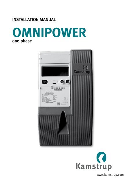
LCD-display<br />
Optical interface<br />
LED (meter constant)<br />
LED breaker status<br />
(only meters with<br />
internal breaker)<br />
Push button<br />
Sealable push-button<br />
Type label<br />
Utility seals<br />
The meter constant LED blinks proportionally to the consumed active energy.<br />
Only authorized personnel must break the utility sealing.<br />
2 55121312_B1_GB_10.2013
Installation manual<br />
The phase indications have various functions. They indicate the two situations described below.<br />
From the connection of the meter:<br />
Indications L1<br />
On<br />
Off<br />
Indications<br />
On<br />
Off<br />
Indicate<br />
Voltage is above minimum limit (160V)<br />
Voltage is below minimum limit (160V)<br />
Indicate<br />
The load is above the minimum (2.3W)<br />
The load is below minimum limit (2.3W)<br />
If the load exceeds the minimum limit and the meter is configured with this reading,<br />
consumption will be indicated via the quadrant reading. The direction of the phase current is<br />
indicated also by the arrow of L1, regardless of configuration.<br />
7-digit identification field<br />
Quadrant indicator<br />
Module indication<br />
Text field<br />
9-digit value field<br />
Unit field<br />
Phase current indication<br />
Breaker symbol<br />
Supply voltage indication<br />
Tamper symbol<br />
Tariff indication<br />
Error symbol<br />
Phase sequence indication<br />
Prepayment-symbol<br />
Radio network symbol<br />
Terminals<br />
Multi core 7 core Massive / terminals<br />
35 mm 2 ≥ 6 mm 2 ≥ 6 mm 2 ≥ 2.5 mm 2<br />
Screw: Pz 2 or straight slot<br />
Torch: 2.5 – 3 Nm<br />
Load control, installation<br />
For meters with load control relay(s). Due to the delay in the meter, it is important to restart the<br />
meter (off/on) when the time is set correctly in the meter. This places the relays in the correct<br />
position and stops the delay timer.<br />
55121312_B1_GB_10.2013<br />
3
Installation manual<br />
With built-in radio<br />
If the meter is supplied with integral radio for establishment of remote reading, the meter<br />
automatically connects to a radio network. The integral radio is equipped with an internal<br />
antenna. The radio signal strength can be read via the system. If the radio signal is not<br />
sufficient, an external antenna must be connected. Please see current documentation on<br />
available antennas.<br />
Mounting a communication module in the meter may influence on radio communication, please<br />
contact <strong>Kamstrup</strong>.<br />
With disconnect function<br />
With this type of meter, it must be checked that the red diode is switched off. This indicates that<br />
the consumer’s supply is disconnected.<br />
Installation dimensions<br />
81.6 81,6<br />
81,6<br />
81.6<br />
177.7 177,7<br />
237,7<br />
237.7<br />
Connection diagrams<br />
The valid connection diagram appears from the type label.<br />
128,7<br />
128.7<br />
1 2 3 4 5 6<br />
L1<br />
N<br />
S0 + P+<br />
-<br />
20 21<br />
4 55121312_B1_GB_10.2013


