Operating Manual - Pro Sound & Lighting
Operating Manual - Pro Sound & Lighting
Operating Manual - Pro Sound & Lighting

You also want an ePaper? Increase the reach of your titles
YUMPU automatically turns print PDFs into web optimized ePapers that Google loves.
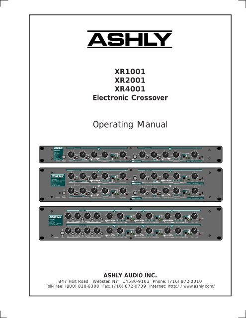
XR1001<br />
XR2001<br />
XR4001<br />
Electronic Crossover<br />
<strong>Operating</strong> <strong>Manual</strong><br />
Channel 1<br />
XR1001<br />
6<br />
4 U 6<br />
4 U 6<br />
1K<br />
Stereo<br />
3<br />
7 3<br />
7<br />
Two-Way<br />
2K<br />
9<br />
Norm<br />
Mono<br />
2<br />
8<br />
Mute 2<br />
8<br />
Mute<br />
3<br />
÷10<br />
3-Way<br />
500<br />
4K<br />
Electr.<br />
1<br />
9 1<br />
9<br />
400 8K<br />
Crossover<br />
0 Low 10<br />
0 High 10 12 2 dB<br />
40 Hz 800<br />
24 dB/Oc tave<br />
Low<br />
Mid<br />
Crossover<br />
Power Output Level<br />
Response Frequency Range<br />
4 U 6<br />
3<br />
7<br />
2<br />
8<br />
1<br />
9 Peak<br />
0 10<br />
Input Level<br />
Channel 2<br />
6<br />
1K<br />
4 U 6<br />
4 U 6<br />
4 U 6<br />
3<br />
7 3<br />
7<br />
2K<br />
3<br />
7<br />
Mode<br />
9<br />
Norm<br />
2<br />
8<br />
Mute 2<br />
8<br />
Mute<br />
3<br />
÷10 2<br />
8<br />
500<br />
1<br />
9 1<br />
9<br />
4K<br />
1<br />
9<br />
0<br />
400 8K<br />
Low 10<br />
0 High10<br />
12 2 dB<br />
40 Hz<br />
0 10<br />
800<br />
Peak<br />
Stereo 2-way<br />
High<br />
Crossover<br />
Input Level<br />
Mono 3-way Output Level<br />
Response Frequency Range Mono 3-Way Input Level<br />
XR2001<br />
Four Channel Two Way<br />
Stereo Three Way<br />
Electronic<br />
Crossover<br />
24 dB/Oc tave<br />
Channel 1<br />
U<br />
U<br />
4 6<br />
4 6<br />
6<br />
1K<br />
3<br />
7 3<br />
7<br />
2K<br />
Norm<br />
2<br />
8 2<br />
8<br />
Mute<br />
Mute<br />
3 500<br />
÷10<br />
1<br />
9 1<br />
9<br />
4K<br />
400 8K<br />
0 Low 10<br />
0 High10<br />
912 2 dB 40 Hz 800<br />
Low<br />
Mid<br />
Output Level<br />
Response Crossover Range<br />
Frequency<br />
Channel 3<br />
U<br />
4 6<br />
U<br />
4 6<br />
6<br />
1K<br />
3<br />
7 3<br />
7<br />
2K<br />
9<br />
Norm<br />
2<br />
8 2<br />
8<br />
Mute<br />
Mute<br />
3 500<br />
÷10<br />
4K<br />
1<br />
9 1<br />
9<br />
400 8K<br />
0 Low 10<br />
0 High 10 12 2 dB 40 Hz 800<br />
Low<br />
Mid<br />
Power<br />
Output Level<br />
Response Crossover<br />
Range<br />
Frequency<br />
U<br />
4 6<br />
3<br />
7<br />
2<br />
8<br />
1<br />
9 Peak<br />
0 10<br />
Input Level<br />
U<br />
4 6<br />
3<br />
7<br />
2<br />
8<br />
1<br />
9 Peak<br />
0 10<br />
Input Level<br />
Channel 2<br />
U<br />
U<br />
4 6<br />
4 6<br />
6<br />
1K<br />
3<br />
7 3<br />
7<br />
2K<br />
Mode<br />
Norm<br />
2<br />
2<br />
8<br />
Mute<br />
Mute<br />
3 500<br />
÷10<br />
1<br />
9 1<br />
9<br />
4K<br />
400 8K<br />
0 Low 10<br />
0 High10<br />
912 2 dB 40 Hz 800<br />
Stereo 2-way<br />
High<br />
Output Level<br />
Response Crossover<br />
Range<br />
Mono 3-way<br />
Frequency<br />
Channel 4<br />
U<br />
U<br />
4 6<br />
4 6<br />
6<br />
1K<br />
3<br />
7 3<br />
7<br />
2K<br />
Mode<br />
Norm<br />
2<br />
2<br />
8<br />
Mute<br />
Mute<br />
3 500<br />
÷10<br />
4K<br />
1<br />
9 1<br />
9<br />
400 8K<br />
0 Low 10<br />
0 High10<br />
912 2 dB 40 Hz 800<br />
High<br />
Stereo 2-way<br />
Output Level<br />
Response Crossover Range<br />
Mono 3-way<br />
Frequency<br />
2<br />
3<br />
1<br />
U<br />
4 6<br />
7<br />
8<br />
9<br />
0 10<br />
Peak<br />
Input Level<br />
Mono 3-Way Input Level<br />
U<br />
4 6<br />
3<br />
7<br />
2<br />
8<br />
1<br />
9<br />
0 10<br />
Peak<br />
Input Level<br />
Mono 3-Way Input Level<br />
Channel 1<br />
6<br />
1K<br />
4K<br />
4 U 6 4 U 6 4 U 6 4 U 6<br />
6<br />
1K<br />
6<br />
4 U 6<br />
3<br />
7 3<br />
7 3<br />
7 3<br />
7<br />
2K<br />
2K<br />
3<br />
7<br />
9<br />
Norm 9<br />
Norm 9<br />
Norm<br />
2<br />
8 2<br />
8 2<br />
8 2<br />
8<br />
2K<br />
3<br />
÷10<br />
8K<br />
÷10<br />
500<br />
3<br />
÷10<br />
2<br />
8<br />
500<br />
3<br />
4K<br />
4K<br />
1<br />
9 1<br />
9 1<br />
9 1<br />
9<br />
12 2 400 8K<br />
1.2K 24K<br />
16K<br />
1<br />
9<br />
XR4001 0 10 0 10 0 10 0 10<br />
12 2 400 8K<br />
12 2<br />
Stereo<br />
dB<br />
40 Hz 0 10<br />
800 Range<br />
dB<br />
40 Hz 800<br />
dB<br />
120 Hz 2.4K<br />
Low Mute Low-Mid Mute High-Mid Mute High Mute<br />
Four Way<br />
Output Level Response Low/Low-Mid<br />
Response Low-Mid/Hi-Mid Range Response Hi-Mid/High Range Input Level<br />
El ectronic Crossover<br />
24 dB/Oc tave<br />
Channel 2<br />
4 U 6 4 U 6 4 U 6 4 U 6<br />
6<br />
1K<br />
6<br />
1K<br />
6<br />
4K<br />
4 U 6<br />
3<br />
7 3<br />
7 3<br />
7 3<br />
7<br />
2K<br />
2K<br />
3<br />
7<br />
9<br />
Norm 9<br />
Norm 9<br />
Norm<br />
2<br />
8 2<br />
8 2<br />
8 2<br />
8<br />
2K<br />
3<br />
÷10<br />
÷10<br />
8K<br />
2<br />
8<br />
500<br />
3 500<br />
3<br />
÷10<br />
1<br />
9 1<br />
9 1<br />
9 1<br />
9<br />
4K<br />
4K<br />
1<br />
9<br />
0 10 0 10 0 10 0 10 12 2 400 8K<br />
12 2 400 8K<br />
12 2 1.2K 24K<br />
16K<br />
0 10<br />
dB<br />
40 Hz 800<br />
dB<br />
dB<br />
Mute Mute Mute Mute<br />
Range<br />
40 Hz 800<br />
120 Hz 2.4K<br />
Low Low-Mid High-Mid High<br />
Power<br />
Output Level<br />
Response Low/Low-Mid<br />
Response Low-Mid/Hi-Mid Range Response Hi-Mid/High Range Input Level<br />
Peak<br />
Peak<br />
ASHLY AUDIO INC.<br />
847 Holt Road Webster, NY 14580-9103 Phone: (716) 872-0010<br />
Toll-Free: (800) 828-6308 Fax: (716) 872-0739 Internet: http://www.ashly.com/
<strong>Operating</strong> <strong>Manual</strong> - XR1001, XR2001, and XR4001 Electronic Crossovers<br />
Table Of Contents<br />
1 INTRODUCTION . . . . . . . . . . . . . . . . . . . . . . . . . . . . . . . . . . . . . . . . . . . . . . . . . . . . . . . . 3<br />
2 UNPACKING . . . . . . . . . . . . . . . . . . . . . . . . . . . . . . . . . . . . . . . . . . . . . . . . . . . . . . . . . . . . 3<br />
3 AC POWER REQUIREMENTS . . . . . . . . . . . . . . . . . . . . . . . . . . . . . . . . . . . . . . . . . . . 3<br />
4 SECURITY COVERS . . . . . . . . . . . . . . . . . . . . . . . . . . . . . . . . . . . . . . . . . . . . . . . . . . . . 3<br />
5 CONTROLS . . . . . . . . . . . . . . . . . . . . . . . . . . . . . . . . . . . . . . . . . . . . . . . . . . . . . . . . . . . . . 4<br />
5.1 Power Switch . . . . . . . . . . . . . . . . . . . . . . . . . . . . . . . . . . . . . . . . . . . . . . . . . . . . . . . . 4<br />
5.2 Input Level . . . . . . . . . . . . . . . . . . . . . . . . . . . . . . . . . . . . . . . . . . . . . . . . . . . . . . . . . . 4<br />
5.3 Crossover Frequency . . . . . . . . . . . . . . . . . . . . . . . . . . . . . . . . . . . . . . . . . . . . . . . . . . 4<br />
5.4 Response . . . . . . . . . . . . . . . . . . . . . . . . . . . . . . . . . . . . . . . . . . . . . . . . . . . . . . . . . . . . 4<br />
5.5 Output Level . . . . . . . . . . . . . . . . . . . . . . . . . . . . . . . . . . . . . . . . . . . . . . . . . . . . . . . . . 5<br />
5.6 Clip Indicator . . . . . . . . . . . . . . . . . . . . . . . . . . . . . . . . . . . . . . . . . . . . . . . . . . . . . . . . 5<br />
6 AUDIO CONNECTIONS AND CABLES . . . . . . . . . . . . . . . . . . . . . . . . . . . . . . . . . . . 6<br />
6.1 Balanced . . . . . . . . . . . . . . . . . . . . . . . . . . . . . . . . . . . . . . . . . . . . . . . . . . . . . . . . . . . . 6<br />
6.2 Unbalanced . . . . . . . . . . . . . . . . . . . . . . . . . . . . . . . . . . . . . . . . . . . . . . . . . . . . . . . . . . 6<br />
6.3 Inputs . . . . . . . . . . . . . . . . . . . . . . . . . . . . . . . . . . . . . . . . . . . . . . . . . . . . . . . . . . . . . . . 6<br />
6.4 Outputs . . . . . . . . . . . . . . . . . . . . . . . . . . . . . . . . . . . . . . . . . . . . . . . . . . . . . . . . . . . . . . 6<br />
6.5 Mono Low Output . . . . . . . . . . . . . . . . . . . . . . . . . . . . . . . . . . . . . . . . . . . . . . . . . . . . 6<br />
6.6 System Phase . . . . . . . . . . . . . . . . . . . . . . . . . . . . . . . . . . . . . . . . . . . . . . . . . . . . . . . . 6<br />
7 TYPICAL APPLICATIONS . . . . . . . . . . . . . . . . . . . . . . . . . . . . . . . . . . . . . . . . . . . . . . 7<br />
7.1 Connecting Into a <strong>Sound</strong> System . . . . . . . . . . . . . . . . . . . . . . . . . . . . . . . . . . . . . . . 7<br />
7.2 Speaker Placement . . . . . . . . . . . . . . . . . . . . . . . . . . . . . . . . . . . . . . . . . . . . . . . . . . . . 7<br />
7.3 XR1001 . . . . . . . . . . . . . . . . . . . . . . . . . . . . . . . . . . . . . . . . . . . . . . . . . . . . . . . . . . . . . 7<br />
7.4 XR2001 . . . . . . . . . . . . . . . . . . . . . . . . . . . . . . . . . . . . . . . . . . . . . . . . . . . . . . . . . . . . . 8<br />
7.5 XR4001 . . . . . . . . . . . . . . . . . . . . . . . . . . . . . . . . . . . . . . . . . . . . . . . . . . . . . . . . . . . . . 8<br />
8 TROUBLESHOOTING TIPS . . . . . . . . . . . . . . . . . . . . . . . . . . . . . . . . . . . . . . . . . . . . . 9<br />
9 DIMENSIONAL DIAGRAM . . . . . . . . . . . . . . . . . . . . . . . . . . . . . . . . . . . . . . . . . . . . . . 9<br />
10 SPECIFICATIONS . . . . . . . . . . . . . . . . . . . . . . . . . . . . . . . . . . . . . . . . . . . . . . . . . . . . . 10<br />
11 WARRANTY INFORMATION . . . . . . . . . . . . . . . . . . . . . . . . . . . . . . . . . . . . . . . . . . . 10<br />
12 SCHEMATICS . . . . . . . . . . . . . . . . . . . . . . . . . . . . . . . . . . . . . . . . . . . . . . . . . . . . . . 11-15<br />
2
<strong>Operating</strong> <strong>Manual</strong> - XR1001, XR2001, and XR4001 Electronic Crossovers<br />
1. INTRODUCTION<br />
Your ASHLY crossover is the product of an intensive<br />
research effort which combined a reexamination<br />
of traditional crossover theory with practical field use.<br />
Over the years, a number of refinements and new models<br />
have been added to our crossover series, but the original<br />
design goals have remained the same: to produce a crossover<br />
which is sonically accurate, is flexible enough to<br />
suit a wide variety of systems, and affords maximum protection<br />
for speakers and drivers.<br />
All Ashly crossovers are based upon the same<br />
powerful state-variable filter circuit, which guarantees that<br />
two adjacent frequency band outputs always remain in<br />
phase. Our crossovers offer a number of useful and unusual<br />
features, including continuous tuning, a response<br />
control, and a unique output stage which maintains low<br />
noise at any level setting. These models also include a<br />
200:1 tuning range, output mute switches, and both TRS<br />
and XLR connectors. Like other Ashly products, your<br />
crossover features low noise and distortion, active balanced<br />
inputs, a peak level indicator, a precision regulated<br />
power supply, protection against abnormal input or output<br />
conditions, and rugged mechanical construction.<br />
Conservative design and an unusually thorough procedure<br />
for quality control have earned Ashly a reputation for<br />
dependability in the recording, sound reinforcement, and<br />
broadcast fields.<br />
Due to the similarity of the operating controls on<br />
our various models, we have prepared this one manual to<br />
cover our complete crossover line. Specific notes on each<br />
model will be found in separate application notes. Many<br />
owners are unaware of the ease with which you can<br />
reconfigure your crossover for nonstandard operation. For<br />
example, a 4-way crossover can easily be used as a mono<br />
2-way with tunable subsonic and ultrasonic cutoff filters,<br />
and a stereo 3-way can function as a mono 5-way crossover.<br />
No internal modifications are necessary, and audio<br />
performance is not compromised. In addition, this manual<br />
covers normal setup and operation and offers troubleshooting<br />
tips. Please take time to read it before<br />
operating your crossover.<br />
transportation damage should the unit again require packing<br />
and shipping. In the event that damage has occurred,<br />
immediately notify your dealer so that a written claim to<br />
cover the damages can be initiated.<br />
The right to any claim against a public carrier<br />
can be forfeited if the carrier is not notified promptly and<br />
if the shipping carton and packing materials are not available<br />
for inspection by the carrier. Save all packing materials<br />
until the claim has been settled.<br />
3. AC POWER REQUIREMENTS<br />
Unless otherwise indicated on the back of the<br />
unit, all crossovers should be connected to a 3-wire<br />
grounded outlet supplying 120 Volts, 50-60 Hz. Some<br />
export models are 240 volts, and are labeled accordingly.<br />
This unit will perform normally from 92 to 130<br />
volts AC. A “brownout” condition occurs when available<br />
AC power falls low enough to take the unit’s DC<br />
power supply out of regulation, increasing noise and lowering<br />
signal headroom. In general, avoid powering your<br />
audio system with AC circuits that additionally run large<br />
refrigeration compressors, air conditioners, electric heaters,<br />
lighting systems, etc.<br />
This unit has an internal line fuse. In the unlikely<br />
event that the fuse should blow, refer the product<br />
to a qualified service technician. Power consumption is<br />
15 watts.<br />
4. SECURITY COVERS<br />
For installations where it is desirable to protect<br />
the front panel controls from tampering or accidental<br />
misadjustment, use the Ashly security cover, which is<br />
available in both single and double rack space sizes. Installation<br />
is simple and does not require removal of the<br />
equipment from your rack. See your Ashly dealer for details.<br />
2. UNPACKING<br />
As a part of our system of quality<br />
control, every Ashly product is carefully<br />
inspected before leaving the factory to ensure<br />
flawless appearance. After unpacking,<br />
please inspect for any physical damage.<br />
Save the shipping carton and all packing<br />
materials , as they were carefully designed<br />
to reduce to minimum the possibility of<br />
Ashly Security Cover Installation<br />
3
<strong>Operating</strong> <strong>Manual</strong> - XR1001, XR2001, and XR4001 Electronic Crossovers<br />
5. CONTROLS<br />
Every Ashly crossover has the following controls:<br />
a Power Switch, an Input Level control, a Crossover Frequency<br />
(Hz) control and Range Switch for each dividing<br />
point, a Response (dB) control, Output Level controls<br />
with Mute Switches, and a Peak Indicator LED. The<br />
XR1001 and XR2001 also have a Mode Switch for selecting<br />
between 2-way and 3-way operation.<br />
5.1 Power Switch<br />
This switch connects AC power to the rest of the<br />
unit. You will know power is on when one of the crossover<br />
frequency range LED indicators is lit. If there is no<br />
light, check to see if the unit is plugged in to a live outlet.<br />
If there is still no light, the internal AC line fuse may<br />
have blown. Refer the unit to a qualified service technician<br />
for fuse replacement.<br />
5.2 Input Level<br />
This control can boost incoming signal up to<br />
+8dB before it reaches the filters, or attenuate the signal<br />
so that it is fully off. Maximum input level is +23dBu.<br />
The “U” shown at the 12:00 position indicates “unity gain”<br />
of the input section. We recommend setting this control<br />
at unity and controlling system levels either prior to the<br />
crossover or at the output level controls.<br />
5.3 Crossover Frequency<br />
This infinitely variable control allows you to select<br />
an appropriate crossover point for your speakers.<br />
Turning the knob clockwise moves the crossover point to<br />
a higher frequency, while turning it counterclockwise<br />
moves it to a lower frequency. Crossover frequencies are<br />
marked on standard ISO 1/3 octave center frequencies<br />
with each octave calibrated. Calibration accuracy is very<br />
good, typically within 1/3 octave or better. If greater<br />
accuracy than this is necessary, measure the actual crossover<br />
frequency with an accurate oscillator/frequency<br />
counter.<br />
To allow a wider tuning range, our crossovers use<br />
a recessed range switch for each frequency control. LED<br />
indicators provide range status as soon as the unit is powered<br />
on. The range switch divides the frequency indicated<br />
on the frequency control by 10 and gives a total<br />
range of 200:1 for each control. Avoid accidental damage<br />
to speakers by muting the outputs before changing<br />
the range switch. Carefully plan and check the frequency<br />
range selected to each driver before sending audio signals<br />
to your speakers.<br />
The choice of crossover frequencies depends on<br />
the type of speakers being used, personal taste, room<br />
acoustics, and many other factors. Experiment to see what<br />
works best for you.<br />
CAUTION: High frequency compression drivers<br />
may be destroyed by the use of too low a crossover<br />
frequency. Follow the driver manufacturer’s recommendations<br />
carefully. Make sure the range switch is properly<br />
set. You may want to install a security cover if the unit is<br />
accessible to untrained people.<br />
5.4 Response<br />
This control, found adjacent to the crossover frequency<br />
control, adjusts the damping of the filter affecting<br />
the response shape of the filters at the crossover point (see<br />
drawing). The dial calibrations refer to the amount of attenuation<br />
effected by the filter at the crossover frequency,<br />
i.e., a setting of 3dB means that the filter’s high-pass and<br />
low-pass outputs are each “rolled off 3dB at the crossover<br />
point”. This describes Butterworth filter response, or a<br />
gentle 3dB peak at the crossover point when the two filter<br />
output signals overlap. To obtain a flat signal, or<br />
“Linkowitz-Riley” response through the crossover region,<br />
set the Response control to “6”. This attenuates each output<br />
of the filter by 6dB at the crossover point (two identical<br />
signals added together yield a +6dB increase). To obtain<br />
a notch at the crossover point, turn down the response<br />
control past “6” to best suit your needs.<br />
4
<strong>Operating</strong> <strong>Manual</strong> - XR1001, XR2001, and XR4001 Electronic Crossovers<br />
The purpose of this control is to help offset the<br />
inaccuracies inherent in typical loudspeakers, thereby<br />
helping you to achieve a flat system response. If you use<br />
a spectrum analyzer to set up your system, adjust the response<br />
control to obtain the flattest response through the<br />
crossover region before any equalization is applied to the<br />
system. If adjusting by ear, we recommend an initial setting<br />
of 6dB. Adjust from this point if the system appears<br />
to have an excess or deficiency of level at the crossover<br />
point.<br />
NOTE: The Response control is not a “slope”<br />
control. A 12dB/octave crossover will always have a slope<br />
of 12dB/octave regardless of the setting of this control.<br />
Likewise, a 24dB/octave crossover will always have a<br />
slope of 24dB/octave. The Response control only affects<br />
filter response shape in the immediate vicinity of the crossover<br />
frequency; the ultimate crossover slope is a fixed<br />
parameter.<br />
5.5 Output Level<br />
The crossover’s output stage operates at unity<br />
gain with the output level controls set at “U”. Max gain<br />
of the output stage is +15dB. In a typical setup, power<br />
amplifier input level controls should be run “full-on”, with<br />
level control being accomplished at the crossover. Adjust<br />
the crossover level controls for best system balance. Keep<br />
in mind that in any multi-amplified system, the higher frequency<br />
speakers tend to be more efficient. Expect to run<br />
the higher frequency level controls at a somewhat lower<br />
setting than the low frequency level controls to obtain<br />
proper frequency response. Note that horn and compression<br />
driver combinations are much more efficient than cone<br />
speakers, often by 12 to 20dB! When cones and compression<br />
drivers are used together, you should expect a much<br />
lower level setting for the horns (all other factors being<br />
equal) to compensate for this difference and obtain proper<br />
balance.<br />
Output Mute switches allow you to isolate individual<br />
or grouped outputs for listening tests without affecting<br />
the settings of any other outputs.<br />
5.6 Clip Indicator<br />
Ashly crossovers feature a peak detection circuit<br />
which monitors signal level at several critical points in<br />
the crossover: input, filters, and outputs. The LED will<br />
flash when signal levels of +20dBu are reached anywhere<br />
in the crossover. Since our crossovers have a nominal<br />
23dB of headroom referenced to a standard operating level<br />
of 0dBu (.77 Volts), a flashing LED warns you that you<br />
are only 3dB from clipping.<br />
Since peak levels are monitored at several key<br />
circuit points, the clip LED can be used to isolate the<br />
source of any overload. If the LED flashes even though<br />
all input and output levels are turned down, the signal<br />
being fed to the crossover is excessive. If the LED flashes<br />
when you turn the Input level control up (with the outputs<br />
still turned down), the overload is occurring in the<br />
filter sections, and you should back the Input level down<br />
a bit. If the LED first flashes when you turn the output<br />
level controls up, then the overload is occurring in the<br />
output stage. In this case, if your power amplifier controls<br />
are at full gain, you are probably severely overdriving<br />
your amplifier.<br />
5
<strong>Operating</strong> <strong>Manual</strong> - XR1001, XR2001, and XR4001 Electronic Crossovers<br />
6. AUDIO CONNECTIONS AND CABLES<br />
6.1 Balanced<br />
Your crossover is provided with two different<br />
connector types, wired in parallel. 1/4 inch stereo phone<br />
jacks and three pin XLR type connectors will allow interfacing<br />
to most professional audio products, with pin 2 hot<br />
(+) and pin 3 (-). The inputs and outputs can be used either<br />
balanced or unbalanced. We recommend balanced<br />
connections between all components in your system, as<br />
this minimizes ground-loop or induced hum and noise.<br />
Pins are<br />
numbered<br />
in the<br />
connector<br />
insert.<br />
6.2 Unbalanced<br />
If either inputs or outputs are used unbalanced,<br />
the signal is on the (+) connection and the (-) connection<br />
must be tied to ground. A mono phone plug used as an<br />
unbalanced connection will automatically ground the ring<br />
of the jack which is the (-) connection. When using a stereo<br />
plug or XLR connector for unbalanced input or output<br />
connections, the signal (-) MUST be tied to ground, or<br />
loss of signal level may result.<br />
Pins are<br />
numbered<br />
in the<br />
connector<br />
insert.<br />
2 = (+)<br />
3 = (-)<br />
1 = (gnd)<br />
2 = (+)<br />
3 = (gnd)<br />
1 = (gnd)<br />
Tip (+)<br />
Ring (-)<br />
Sleeve (Ground)<br />
Stereo Phone Plug<br />
used for balanced<br />
Balanced Audio Connectors<br />
Tip (+)<br />
Sleeve (Ground)<br />
Mono Phone Plug<br />
used for unbalanced<br />
Unbalanced Audio Connectors<br />
XLR Male<br />
XLR Male<br />
6.3 Inputs<br />
Inputs are 20KΩ active balanced, or 10KΩ unbalanced.<br />
6.4 Outputs<br />
The outputs on Ashly crossovers are low impedance<br />
(200 ohms typical) pseudo-balanced type using both<br />
a 3-pin male XLR connector and standard 1/4" phone jack.<br />
Pseudo-balanced lines, while not carrying a truly differential<br />
signal, have an equivalent line impedance on both<br />
(+) and (-) lines. This allows for long cable runs from the<br />
crossover into balanced inputs without compromising<br />
common mode rejection of unwanted noise. To realize<br />
maximum headroom, terminate outputs into loads of 600<br />
ohms or greater.<br />
6.5 Mono Low Output<br />
Ashly models XR2001 and XR4001 have an additional<br />
jack labeled MONO LOW OUT. This output represents<br />
the sum of low frequency outputs of both channels,<br />
and is a function of BOTH low level controls. It is<br />
typically used for driving mono sub-woofers in a stereo<br />
system, reducing the number of power amps needed. Connectors<br />
and wiring are the same as the other outputs. If<br />
you are using a mono low output, you may also use the<br />
normal low frequency outputs to drive other speaker systems;<br />
any or all of the low frequency outputs may be<br />
used at any given time without interaction between outputs.<br />
6.6 System Phase<br />
The outputs of all Ashly crossovers are in phase<br />
with the input. Assuming that your power amplifiers do<br />
not invert phase (most do not), the signals from all your<br />
amps should be in phase. If all speakers are the same<br />
brand, it is easy to keep them in phase. With different<br />
brands of speakers used together, phasing becomes a little<br />
more confusing. It is important to keep all the speakers<br />
within each band in phase with each other, and equally<br />
important to keep all bands of the system in phase as well.<br />
If this is not done, loss of level and pattern control at the<br />
crossover frequency will result.<br />
Phase of CONE speakers can be checked by connecting<br />
a 1.5 volt battery to the speaker and observing<br />
which way the cone moves. Don’t try this with compression<br />
drivers! The most common convention is that (+)<br />
voltage on the (+) terminal moves the cone forward. A<br />
notable exception to this convention is JBL. A (+) voltage<br />
on the red terminal of a JBL speaker moves the cone<br />
backward. If all your speakers are the same brand, just<br />
connect them all the same way; if not, it’s best to test.<br />
Unfortunately, compression drivers cannot be tested this<br />
way. Ask the driver manufacturer.<br />
6
<strong>Operating</strong> <strong>Manual</strong> - XR1001, XR2001, and XR4001 Electronic Crossovers<br />
8. TROUBLESHOOTING TIPS<br />
8.1 No Output<br />
Check AC power - are LED indicators on? Check<br />
in/out connections, are they reversed? Are you<br />
sure you have input signal?<br />
8.2 Peak light flashes frequently<br />
The level is too high somewhere in the crossover.<br />
Try turning down individual output levels<br />
and then the input until the peak LED stays off.<br />
If the peak LED continues to flash when all of<br />
the crossover level controls are turned down, then<br />
the crossover is being fed excessively high levels<br />
from a previous piece of equipment. Turn<br />
down your driving source!<br />
8.3 Distorted sound<br />
Is the peak light flashing? If it is, an overload is<br />
occurring within the crossover, and may also be<br />
occurring in other parts of the system. If the peak<br />
light is not flashing, the distortion is occurring<br />
somewhere outside the crossover.<br />
8.4 Excessive hum or noise<br />
Hum will usually be caused by a “ground loop”<br />
between components. Try using the suggested<br />
balanced input and output hookups if the other<br />
pieces of equipment used in conjunction with your<br />
crossover have balanced inputs and outputs.<br />
Noise can be caused by insufficient drive signal.<br />
Ashly crossovers provide the best noise and headroom<br />
performance when the input signal is 0 to<br />
+4dBu level and power amplifier sensitivity is<br />
higher than 1 volt. Unshielded cables, improperly<br />
wired connections, and cable with broken strands<br />
(shorts, etc.) are the most common problems.<br />
Please properly maintain and inspect your wiring<br />
first.<br />
If you still need help, get in touch with your Ashly<br />
dealer or call Ashly direct - (800) 828-6308. In<br />
New York State dial (716) 872-0010.<br />
9. DIMENSIONAL DIAGRAM<br />
9
<strong>Operating</strong> <strong>Manual</strong> - XR1001, XR2001, and XR4001 Electronic Crossovers<br />
10. SPECIFICATIONS<br />
10.1 Input Level Control<br />
10.2 Damping/Response<br />
10.3 Output Level Control<br />
10.4 Input Impedance<br />
10.5 Output Impedance<br />
-∞ to +8.5dB<br />
2dB - 12dB<br />
-∞ to +15dB<br />
20KΩ Balanced<br />
200Ω Quasi-Balanced<br />
11. WARRANTY INFORMATION<br />
We thank you for expression of confidence in<br />
Ashly products. The unit you have just purchased is protected<br />
by a limited five year warranty. To establish the<br />
warranty, you must first complete and mail the warranty<br />
card attached to your product.<br />
Fill out the information below for your records.<br />
Model Number ______________________<br />
Serial Number _______________________<br />
Dealer _____________________________<br />
Date of Purchase_____________________<br />
10.6 Maximum Input Level<br />
+23dBu<br />
10.7 Maximum Output Level<br />
+23dBu<br />
Dealer’s Address_____________________<br />
___________________________________<br />
___________________________________<br />
10.8 Frequency Response<br />
10.9 Distortion<br />
10.10 Slew Rate<br />
10.11 Hum and Noise<br />
10.12 Power Requirements<br />
10.13 Shipping Weight<br />
XR1001:<br />
XR2001:<br />
XR4001:<br />
±.5dB 20Hz-20KHz<br />
<strong>Operating</strong> <strong>Manual</strong> - XR1001, XR2001, and XR4001 Electronic Crossovers<br />
13. SCHEMATICS:<br />
11
<strong>Operating</strong> <strong>Manual</strong> - XR1001, XR2001, and XR4001 Electronic Crossovers<br />
Block Diagram: XR-1001, XR-2001<br />
12
<strong>Operating</strong> <strong>Manual</strong> - XR1001, XR2001, and XR4001 Electronic Crossovers<br />
Schematic Diagram: XR-1001, XR-2001<br />
13
<strong>Operating</strong> <strong>Manual</strong> - XR1001, XR2001, and XR4001 Electronic Crossovers<br />
Block Diagram: XR-4001<br />
14
<strong>Operating</strong> <strong>Manual</strong> - XR1001, XR2001, and XR4001 Electronic Crossovers<br />
Schematic Diagram: XR-4001<br />
15
<strong>Operating</strong> <strong>Manual</strong> - XR1001, XR2001, and XR4001 Electronic Crossovers<br />
ASHLY AUDIO INC. 847 Holt Road Webster, NY 14580-9103<br />
Phone: (716) 872-0010 Fax: (716) 872-0739<br />
Toll Free (800) 828-6308 Internet: http://www.ashly.com/<br />
© 1997 by Ashly Audio Corporation. All rights reserved worldwide.<br />
Printed in USA 1/97 XR Rev 4