CPX Series Owner's Manual - Crest Audio
CPX Series Owner's Manual - Crest Audio
CPX Series Owner's Manual - Crest Audio

You also want an ePaper? Increase the reach of your titles
YUMPU automatically turns print PDFs into web optimized ePapers that Google loves.
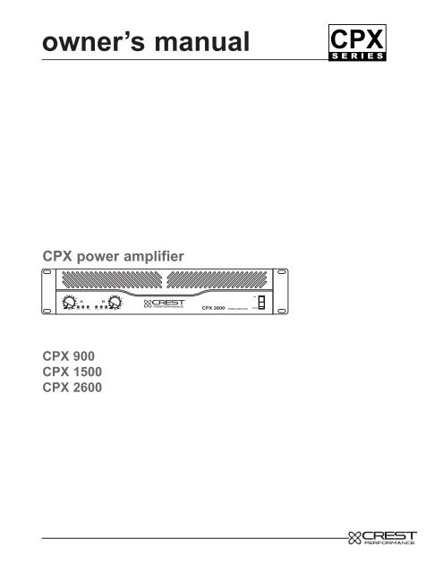
owner’s manual<br />
<strong>CPX</strong><br />
S E R I E S<br />
<strong>CPX</strong> power amplifier<br />
20 23<br />
16<br />
26<br />
A<br />
6<br />
29<br />
32<br />
(dB)<br />
PWR SIG GCL TM<br />
20 23<br />
16<br />
26<br />
B<br />
6<br />
29<br />
GCL TM<br />
SIG PWR<br />
32<br />
(dB)<br />
<strong>CPX</strong> 2600<br />
POWER AMPLIFIER<br />
ON<br />
POWER<br />
<strong>CPX</strong> 900<br />
<strong>CPX</strong> 1500<br />
<strong>CPX</strong> 2600
important precautions<br />
1 Save the carton and packing materials!<br />
Should you ever need to ship<br />
the unit, use only the original factory<br />
packing.<br />
For replacement packaging, call <strong>Crest</strong><br />
<strong>Audio</strong>’s Customer Service Department<br />
directly.<br />
2 Read all documentation before<br />
operating your equipment. Retain<br />
all documentation for future reference.<br />
3 Follow all instructions printed on<br />
unit chassis for proper operation.<br />
4 Never hold a power switch or circuit<br />
breaker in the on-position, if<br />
it won’t stay there by itself!<br />
5 Do not use the unit if the electrical<br />
power cord is frayed or broken.<br />
The power supply cords should be<br />
routed so that they are not likely to<br />
be walked on or pinched by items<br />
placed upon or against them.<br />
6 Always operate the unit with the<br />
AC ground wire connected to the<br />
electrical system ground.<br />
Precautions should be taken so that<br />
the means of grounding of a piece of<br />
equipment is not defeated.<br />
7 Damage caused by connection to<br />
improper AC voltage is not covered<br />
by any warranty. Mains voltage<br />
must be correct and the same as that<br />
printed on the rear of the unit.<br />
8 Do not ground any hot (red) terminal.<br />
Never connect a hot (red) output to<br />
ground or to another hot (red) output!<br />
9 Power down and disconnect units<br />
from mains voltage before making<br />
connections.<br />
10 Do not drive the inputs with a<br />
signal level greater than that<br />
required to enable equipment to<br />
reach full output.<br />
Do not run the output of any amplifier<br />
channel back into another<br />
channel’s input.<br />
Do not parallel- or series-connect<br />
an amplifier output with any<br />
other amplifier output.<br />
<strong>Crest</strong> <strong>Audio</strong> is not responsible for<br />
damage to loudspeakers for any reason.<br />
Do not connect the inputs or outputs<br />
of amplifiers to any other<br />
voltage source: such as a battery,<br />
mains source, or power supply,<br />
regardless of whether the amplifier<br />
is turned on or off.<br />
Connecting amplifier outputs to<br />
oscilloscopes or other test equipment<br />
while the amplifier is in<br />
bridged mono mode may damage<br />
both the amplifier and test equipment!<br />
Do not spill water or other liquids<br />
into or on the unit, or operate the<br />
unit while standing in liquid.<br />
Do not block fan intake or<br />
exhaust ports.<br />
Do not operate equipment on a<br />
surface or in an environment<br />
which may impede the normal<br />
flow of air around the unit: such<br />
as a bed, rug, weathersheet, carpet,<br />
or completely enclosed rack.<br />
If the unit is used in an extremely<br />
dusty or smoky environment:<br />
the unit should be periodically<br />
“blown free” of foreign matter.<br />
Do not use the unit near stoves,<br />
heat registers, radiators, or other<br />
heat producing devices.<br />
The power cord of equipment<br />
should be unplugged from the outlet<br />
when left unused for a long period<br />
of time.<br />
Service Information<br />
Do not remove the cover!<br />
Removing the cover will expose you<br />
to potentially dangerous voltages.<br />
There are no user serviceable parts<br />
inside.<br />
Equipment should be serviced<br />
by qualified service personnel<br />
when:<br />
A. The power supply cord or the plug has<br />
been damaged.<br />
B. The equipment has been exposed to<br />
rain.<br />
C. The equipment does not appear to<br />
operate normally, or exhibits a marked<br />
change in performance.<br />
D. The equipment has been dropped, or<br />
the enclosure damaged.<br />
To obtain service:<br />
contact your nearest <strong>Crest</strong> <strong>Audio</strong><br />
Service Center, Distributor, Dealer,<br />
or <strong>Crest</strong> <strong>Audio</strong> at 201.909.8700<br />
USA<br />
or visit www.crestaudio.com for<br />
additional information.<br />
email: techserve@crestaudio.com
<strong>CPX</strong> Owner’s manual<br />
1<br />
2<br />
3<br />
4<br />
5<br />
6<br />
introduction p.3<br />
installation p.5<br />
unpacking<br />
mounting<br />
cooling and ventilation<br />
powering<br />
maintenance<br />
features overview p.11<br />
front panel<br />
rear panel<br />
application details p.23<br />
installations<br />
bridged<br />
GCL<br />
connections p.27<br />
input<br />
output<br />
Specifications p.31<br />
wire gauge charts p.32, 33<br />
contents<br />
p. 1
1 introduction<br />
<strong>CPX</strong> owner’s manual<br />
p. 2
introduction 1<br />
welcome<br />
Congratulations on your purchase of a new <strong>CPX</strong> <strong>Series</strong> power amplifier, and<br />
thank you for your confidence in <strong>Crest</strong> <strong>Audio</strong> products. You are among the growing<br />
number of audio professionals who have made <strong>Crest</strong> <strong>Audio</strong> one of the world’s<br />
leading suppliers of professional and commercial/industrial audio systems.<br />
For your safety, please read the Important Precautions section before installing<br />
and operating the amplifier. The <strong>Crest</strong> <strong>Audio</strong> <strong>CPX</strong> <strong>Series</strong> amplifiers are designed<br />
for high operating efficiency and accurate sonic performance across the full audio<br />
bandwidth, even under stressful conditions.<br />
<strong>CPX</strong> series amplifiers feature a 2-way crossover and sub-sonic (low-cut) filter for<br />
each channel. Crossover frequencies are fixed at 150 Hz, allowing subwoofers to<br />
be driven at extremely high sound pressure levels, and the filters cut at 40 Hz to<br />
prevent low-end rumble. Using proven technology gained through years of amplifier<br />
design, this unit takes advantage of rugged TO-3P output devices mounted<br />
on massive aluminum extrusions and dissipates heat via an extremely quiet and<br />
effective 2-speed fan. <strong>CPX</strong> amplifiers employ mammoth toroidal power transformers<br />
and offer impressive specifications and features not found on similarly<br />
priced competitive units.<br />
These amps are designed to drive a 2-ohm load per channel, thus achieving awesome<br />
performance levels into 4 ohms in BRIDGE mode. <strong>CPX</strong> amplifiers are<br />
ruggedly constructed, rack-mountable pieces of gear with superb patching capability,<br />
allowing superior flexibility in application.<br />
Front panel features include calibrated, detented gain (dB) controls and LED indicators<br />
for power (PWR), signal presence (SIG), and GCL (Gain Comparator<br />
Limiter) activation on each channel, as well as a rocker mains POWER switch.<br />
The back panel contains an IEC connector for the mains power cord, a mains circuit<br />
breaker with reset, and the critical cooling fan opening. This opening should<br />
have an adequate supply of cool air and should never be blocked or restricted.<br />
Also on the back panel are the input and output sections, including an input barrier<br />
strip for permanent installations. Each channel input section includes a combo<br />
XLR / ¼" phone jack connector, THRU/LOW out and HIGH out ¼" jacks, and activation<br />
switches for the LOW CUT filter and crossover (150 Hz XOVER). Channel<br />
output sections feature dual shock-proof binding posts and 4-conductor Speakon<br />
connectors. An additional 4-conductor Speakon connector allows BRIDGE mode<br />
output.<br />
p. 3
2<br />
installation<br />
<strong>CPX</strong> owner’s manual<br />
p. 4
installation 2<br />
what to do with the shipping carton<br />
unpacking<br />
proper rack-mounting technique<br />
keeping the amplifier cooled<br />
mounting<br />
routine maintenance practices<br />
cooling and<br />
ventilation<br />
maintenance<br />
p. 5
2<br />
installation<br />
<strong>CPX</strong> owner’s manual<br />
unpacking<br />
Please inspect the amplifier carefully immediately after unpacking. If<br />
you find any damage, notify your supplier/dealer immediately. Only the<br />
shipper may file a damage claim with the carrier for damage incurred<br />
during shipping. Be sure to save the carton and all packing materials<br />
for the carrier’s inspection.<br />
If the packing materials are in good condition, please save them.<br />
If you ever need to ship the unit anywhere without mounting it in a rack,<br />
you should take advantage of the original factory packing materials in<br />
order to avoid unnecessary damage.<br />
For replacement packaging,<br />
call <strong>Crest</strong> <strong>Audio</strong>’s<br />
Customer Service<br />
Department directly.<br />
see—service and support<br />
p. 6
THRU<br />
installation<br />
2<br />
mounting<br />
All <strong>CPX</strong> <strong>Series</strong> amplifiers mount in standard 19-inch racks and occupy two rack<br />
spaces. Use of rear supports is highly recommended in all mobile and touring<br />
sound systems.<br />
<strong>CPX</strong> Front panel<br />
front<br />
height<br />
3.47"/<br />
88 mm<br />
16<br />
6<br />
20 23<br />
(dB)<br />
32<br />
26<br />
29<br />
A<br />
16<br />
B<br />
6<br />
PWR SIG GCL TM<br />
GCL TM<br />
SIG PWR<br />
20 23<br />
(dB)<br />
26<br />
29<br />
32<br />
<strong>CPX</strong> 2600<br />
POWER AMPLIFIER<br />
ON<br />
POWER<br />
front width 19"/483mm<br />
<strong>CPX</strong> rear panel<br />
rear width 17"/432mm<br />
front<br />
height<br />
3.47"/<br />
88mm<br />
CAUTION<br />
BREAKER WARNING: TO REDUCE THE RISK OF FIRE OR<br />
ELECTRIC SHOCK DO NOT EXPOSE THIS EQUIPMENT<br />
15 TO RAIN OR MOISTURE.<br />
A AVIS: RISQUE DE CHOC ELECTRIQUE-NE PAS OUVRIR.<br />
M<br />
P<br />
CHANNEL B<br />
BRIDGE<br />
BRIDGE<br />
- + + -<br />
CHANNEL A<br />
BRIDGE<br />
OUT STEREO/<br />
IN BRIDGE<br />
GCL TM<br />
OUT ENABLE /<br />
IN DEFEAT<br />
CHANNEL A INPUT<br />
LOW CUT<br />
150 Hz<br />
X OVER<br />
BAL. LOW Z<br />
HIGH OUT LOW OUT<br />
HIGH Z<br />
LOW CUT<br />
150 Hz<br />
X OVER<br />
A<br />
+<br />
-<br />
GND<br />
B<br />
-<br />
+<br />
MOUNT IN RACK ONLY - INSTALLER SUR<br />
SUPPORT DE MONTAGE SEULEMENT<br />
CHANNEL B<br />
OUTPUT<br />
CHANNEL A<br />
CHANNEL B INPUT<br />
<strong>CPX</strong> side view<br />
depth16"<br />
p. 7
2<br />
installation<br />
<strong>CPX</strong> owner’s manual<br />
INSTALLATION<br />
<strong>CPX</strong> professional power amplifiers are designed for durability in commercial<br />
installations and provide the quality performance required in<br />
studio and home applications. They are 2-rack-space units of 16" (406<br />
mm) depth designed to mount in a standard 19" rack. Rear mounting<br />
ears are provided for additional support. The minimum rack depth<br />
required from the mounting surface is 17" (432 mm) to allow adequate<br />
connector clearance.<br />
cooling and ventilation<br />
<strong>CPX</strong> amplifiers use a forced air cooling system to maintain a low, even<br />
operating temperature.<br />
Air is drawn in by a DC fan on the rear panel, flows through the cooling<br />
fins and then exhausts through the front panel vent.<br />
Heatsink temperature is monitored and controls the variable speed<br />
fan. Fan speed increases only as required, keeping fan noise to a minimum.<br />
Make certain that there<br />
is enough space<br />
around the front and<br />
rear of the amplifier to<br />
allow the heated air to<br />
escape. When mounting<br />
in a rack, try to<br />
avoid using doors or<br />
covers on the front and<br />
rear of the enclosure;<br />
the exhaust air must<br />
not be impeded<br />
suggestion<br />
In racks with closed<br />
backs allow at least<br />
one standard-rackspace<br />
opening for<br />
every four amps.<br />
If the heatsink surpasses it’s maximum allowed temperature, the thermal<br />
protection circuit will activate and open the output relays allowing<br />
the amplifier to cool to a safe temperature. Thermal protect activation<br />
only occurs under extreme thermal conditions and is not part of normal<br />
operation.<br />
p. 8
installation 2<br />
Basic setup<br />
Rack mount the amplifier in the location where it is to be used, remembering to<br />
allow for adequate access and cooling space. Make all the connections to the<br />
proper INPUT connectors on the desired channel. Select the proper mode configuration<br />
(STEREO or BRIDGE). Connect speakers to the proper OUTPUT connectors,<br />
reviewing carefully the impedance and phase considerations. With the<br />
POWER switch OFF, connect the IEC cord to the amplifier and then to a suitable<br />
electrical outlet to allow proper current draw. With both channel gain (dB) controls<br />
at their fully counterclockwise (-8) settings, turn the POWER switch to ON, and<br />
slowly raise the gain controls to desired settings. Please carefully review this<br />
manual. It covers all this information in greater detail.<br />
maintenance<br />
<strong>CPX</strong> amplifiers require no routine maintenance other than checking the cooling<br />
fans to make sure they’re unblocked and working.<br />
If the amplifier is used in an extremely dusty or smoky environment , the unit<br />
should be periodically “ blown free “ ( using compressed air ) of any foreign matter<br />
that may have built up inside the unit.<br />
Users will not need to make any adjustments to the amplifier during it’s lifetime.<br />
There are no user-serviceable parts or adjustments that require opening the<br />
amplifier.<br />
p. 9
3<br />
features overview<br />
<strong>CPX</strong> owner’s manual<br />
p. 10
features overview 3<br />
location of connectors and controls<br />
front panel<br />
Descriptions of connectors and controls<br />
rear panel<br />
p. 11
3<br />
features overview<br />
<strong>CPX</strong> owner’s manual<br />
<strong>CPX</strong> Front panel<br />
1 2 3 4 5 6<br />
16<br />
6<br />
20 23<br />
(dB)<br />
32<br />
26<br />
29<br />
A<br />
B<br />
PWR SIG GCL TM<br />
GCL TM<br />
SIG PWR<br />
16<br />
6<br />
20 23<br />
26<br />
29<br />
32<br />
(dB)<br />
<strong>CPX</strong> 2600<br />
POWER AMPLIFIER<br />
ON<br />
POWER<br />
p. 12
features overview 3<br />
front panel<br />
1 Channel Level attenuators<br />
Two input attenuators adjust level for their respective amplifier channels. In<br />
Bridged Mono and Parallel modes, the channel A attenuator controls overall<br />
signal level (see rear panel mode switch description).<br />
2 Power LEDs (PWR)<br />
These indicators illuminate when the AC mains power is being supplied to the<br />
amp and both channels are operational. If either channel experiences fault conditions,<br />
exceeds safe operating temperature limits, or if the mains circuit breaker<br />
trips; both channel power LEDs will be dark, indicating "shutdown". If the<br />
BRIDGE mode is selected, the PWR indicator on channel B will remain dark as<br />
a positive indication of this mode selection.<br />
3 Signal activity LED’s (sig)<br />
These indicators illuminate when the associated channel output signal level<br />
exceeds 1 VRMS.<br />
4 GCL Active LED’s<br />
These indicators illuminate when GCL compression is taking place in the associated<br />
channel. With the GCL ENABLE / DEFEAT switch on the back panel in<br />
the ENABLE position, these LEDs indicate clipping is occurring in the corresponding<br />
channel. The <strong>Crest</strong> GCL limiting system will be covered in greater<br />
detail later in this manual.<br />
5 Fan Outlet Grill<br />
<strong>CPX</strong> <strong>Series</strong> amplifiers are cooled by a single rear-mounted fan. Cool air flows<br />
over the heat sink and exhausts through the front grill. Make sure this outlet<br />
remains clear to allow unrestricted airflow.<br />
6 Power switch<br />
This heavy-duty, rocker-type switch turns ON the mains power to the amplifier.<br />
When the mains power is applied, there is a 3-second delay in activation of the<br />
unit. This reduces/eliminates the turn-on transients associated with the system<br />
equipment connected to the amplifier and protects loudspeakers.<br />
p. 13
3<br />
features overview<br />
<strong>CPX</strong> owner’s manual<br />
<strong>CPX</strong> Rear Panel<br />
7<br />
CAUTION<br />
BREAKER WARNING: TO REDUCE THE RISK OF FIRE OR<br />
ELECTRIC SHOCK DO NOT EXPOSE THIS EQUIPMENT<br />
15 TO RAIN OR MOISTURE.<br />
A AVIS: RISQUE DE CHOC ELECTRIQUE-NE PAS OUVRIR.<br />
M<br />
P<br />
CHANNEL B<br />
BRIDGE<br />
BRIDGE<br />
- + + -<br />
CHANNEL A<br />
BRIDGE<br />
OUT STEREO/<br />
IN BRIDGE<br />
GCL TM<br />
OUT ENABLE /<br />
IN DEFEAT<br />
CHANNEL A INPUT<br />
LOW CUT<br />
150 Hz<br />
X OVER<br />
A<br />
THRU<br />
BAL. LOW Z<br />
HIGH OUT LOW OUT<br />
GND<br />
HIGH Z<br />
LOW CUT<br />
B<br />
150 Hz<br />
X OVER<br />
+<br />
-<br />
-<br />
+<br />
MOUNT IN RACK ONLY - INSTALLER SUR<br />
SUPPORT DE MONTAGE SEULEMENT<br />
CHANNEL B<br />
OUTPUT<br />
CHANNEL A<br />
CHANNEL B INPUT<br />
8<br />
p. 14
features overview 3<br />
rear panel<br />
7 Circuit breaker<br />
There is one circuit BREAKER on the <strong>CPX</strong> amplifier. This breaker is provided<br />
to limit current to the associated power transformer, and protect it from overheating<br />
and possible destruction due to fault conditions in the unit. The trip current<br />
values have been carefully chosen to allow reasonable continuous power<br />
output performance, while still protecting the power transformer. This breaker<br />
should not trip unless there is a fault in the amplifier circuitry that causes excessive<br />
mains current draw. However, abnormal conditions such as a short circuit<br />
on either or both channels, or continuous operation at overload or clipping<br />
(especially into 2-ohm loads per channel or 4-ohm bridge load) can cause the<br />
breaker to trip. If this occurs, turn the POWER switch OFF and reset the breaker,<br />
after waiting a brief period of time to allow the unit to cool down. Efforts<br />
should be made to correct the cause of the overload if possible. When tripped,<br />
the button on the BREAKER will be outward approximately ¼" and can be<br />
reset by pushing inward and upward. A normal reset button is relatively flat. If<br />
the breaker trips instantly each time you attempt to turn the unit on, it should be<br />
taken to a qualified <strong>Crest</strong> Service Center for repair.<br />
8 IEC Mains connector<br />
This is a standard IEC power connector. An AC mains cord having the appropriate<br />
AC plug and ratings for the intended operating voltage is included in the<br />
carton.<br />
US Domestic AC Mains cord (not pictured)<br />
The mains cord supplied with the unit is a heavy-duty, 3-conductor type with a<br />
conventional 120 VAC plug with ground pin. It should be connected to an independent<br />
circuit capable of continuously supporting at least 15 amps. This is<br />
particularly critical for sustained high-power applications. If the outlet used does<br />
not have a ground pin, a suitable grounding adapter should be used and the<br />
third wire grounded properly.<br />
Never break off the ground pin on any equipment. It is provided for your safety.<br />
The use of extension cords should be avoided but, if necessary, always use a<br />
3-wire type with at least a #14 AWG wire size. The use of lighter wire will<br />
severely limit the power capability of this amplifier. Always use a qualified electrician<br />
to install any new electrical equipment. To prevent the risk of shock or<br />
fire hazard, always be sure that the amplifier and all associated equipment is<br />
properly grounded.<br />
p. 15
3<br />
features overview<br />
<strong>CPX</strong> owner’s manual<br />
<strong>CPX</strong> Rear Panel<br />
10 11<br />
CAUTION<br />
BREAKER WARNING: TO REDUCE THE RISK OF FIRE OR<br />
ELECTRIC SHOCK DO NOT EXPOSE THIS EQUIPMENT<br />
15 TO RAIN OR MOISTURE.<br />
A AVIS: RISQUE DE CHOC ELECTRIQUE-NE PAS OUVRIR.<br />
M<br />
P<br />
CHANNEL B<br />
BRIDGE<br />
BRIDGE<br />
- + + -<br />
CHANNEL A<br />
BRIDGE<br />
OUT STEREO/<br />
IN BRIDGE<br />
GCL TM<br />
OUT ENABLE /<br />
IN DEFEAT<br />
CHANNEL A INPUT<br />
LOW CUT<br />
150 Hz<br />
X OVER<br />
A<br />
THRU<br />
BAL. LOW Z<br />
HIGH OUT LOW OUT<br />
GND<br />
HIGH Z<br />
LOW CUT<br />
B<br />
150 Hz<br />
X OVER<br />
+<br />
-<br />
-<br />
+<br />
MOUNT IN RACK ONLY - INSTALLER SUR<br />
SUPPORT DE MONTAGE SEULEMENT<br />
CHANNEL B<br />
OUTPUT<br />
CHANNEL A<br />
CHANNEL B INPUT<br />
9<br />
p. 16
features overview 3<br />
rear panel<br />
9 Binding post outputs<br />
Shockproof binding post speaker outputs are provided on the <strong>CPX</strong> amplifier.<br />
For each channel, the outputs are in parallel and the speaker connection<br />
cables can be terminated with banana plugs or stripped wires for use in the<br />
binding post terminals, or can be connected using the Speakon outputs (9). For<br />
sustained high-power applications, either outputs can be used; however, exercise<br />
care to assure the correct speaker phasing. The red binding posts are the<br />
signal outputs from each channel, and the black binding posts are chassis<br />
ground. The red binding post should be connected to the positive inputs of the<br />
associated loudspeakers. For BRIDGE mode operation, only the red binding<br />
posts are used and the associated loudspeaker load is connected between the<br />
two red posts.<br />
WARNING…Regardless of what connections are used, the minimum parallel<br />
speaker load should always be limited to 2 ohms per channel or 4 ohms<br />
BRIDGE mode for any application. Operation at loads of 4 ohms per channel,<br />
or 8 ohms BRIDGE mode, is more desirable for sustained operation applications<br />
because the amplifier will run much cooler at this loading. Operation<br />
above 4 ohms per channel and even open-circuit conditions can always be<br />
considered safe, but sustained operation at loads below 2 ohms could result in<br />
temporary amplifier shut down due to the thermal limit circuitry.<br />
10 Speakon outputs<br />
<strong>CPX</strong> amplifiers utilize three 4-conductor Speakon connectors, one for each<br />
channel and one for BRIDGE mode. Please refer to the BRIDGE MODE section<br />
of this manual before attempting to use this mode. For each channel<br />
Speakon, the same impedance rules apply as with the binding posts. Internally,<br />
all the Speakons are wired in what is called the "high current" mode, with pins<br />
1+ and 2+ in parallel, and pins 1- and 2- in parallel. For the CHANNEL A and<br />
CHANNEL B Speakons, the respective channel output appears on pins 1+ and<br />
2+. Pins 1- and 2- are chassis ground. For the BRIDGE Speakon, CHANNEL<br />
A appears on pins 1+ and 2+, and CHANNEL B appears on pins 1- and 2-.<br />
Always check the Speakon connector wiring carefully before using.<br />
11 Mode switch<br />
This switch is used to select STEREO or BRIDGE mode operation. It is a conventional<br />
push-push type, requiring a small "tool" to activate. The IN position is<br />
BRIDGE mode; the OUT position is STEREO mode. Exercise care when<br />
selecting the BRIDGE mode. Accidental selection of this mode could damage<br />
loudspeakers, particularly in bi-amped systems. Amplifier BRIDGE mode theory<br />
will be covered later in this manual.<br />
p. 17
3<br />
features overview<br />
<strong>CPX</strong> Rear Panel<br />
<strong>CPX</strong> owner’s manual<br />
CAUTION<br />
BREAKER WARNING: TO REDUCE THE RISK OF FIRE OR<br />
ELECTRIC SHOCK DO NOT EXPOSE THIS EQUIPMENT<br />
15 TO RAIN OR MOISTURE.<br />
A AVIS: RISQUE DE CHOC ELECTRIQUE-NE PAS OUVRIR.<br />
M<br />
P<br />
CHANNEL B<br />
BRIDGE<br />
BRIDGE<br />
- + + -<br />
CHANNEL A<br />
BRIDGE<br />
OUT STEREO/<br />
IN BRIDGE<br />
GCL TM<br />
OUT ENABLE /<br />
IN DEFEAT<br />
CHANNEL A INPUT<br />
LOW CUT<br />
150 Hz<br />
X OVER<br />
A<br />
THRU<br />
BAL. LOW Z<br />
HIGH OUT LOW OUT<br />
GND<br />
HIGH Z<br />
LOW CUT<br />
B<br />
150 Hz<br />
X OVER<br />
+<br />
-<br />
-<br />
+<br />
MOUNT IN RACK ONLY - INSTALLER SUR<br />
SUPPORT DE MONTAGE SEULEMENT<br />
CHANNEL B<br />
OUTPUT<br />
CHANNEL A<br />
CHANNEL B INPUT<br />
12<br />
13 14 15<br />
p. 18
features overview 3<br />
rear panel<br />
12 GCL (Gain Comparator Limiter) switch<br />
This switch is used to enable or defeat the GCL limiter circuitry. It is also a conventional<br />
push-push type, requiring a small "tool" to activate. The IN position is DEFEAT; the OUT<br />
position is ENABLE. Normally, the GCL function should be enabled to minimize the possibility<br />
of either or both channels going into clipping or overload. With this feature defeated,<br />
a severe overload could cause the mains circuit breaker to trip. The <strong>Crest</strong> GCL limiting<br />
system will be covered in greater detail later in this manual.<br />
13 Fan grill<br />
A 2-speed DC fan supplies cool air to the amplifier. THIS INTAKE SHOULD NEVER BE<br />
BLOCKED! The fan switches to high speed automatically when the unit requires additional<br />
cooling. At idle and cool, the fan should be in low speed. The fan should never<br />
stop unless the amplifier is switched OFF or the AC mains power source is interrupted.<br />
14 Combo input connector<br />
The combo connector offers both female XLR and ¼" phone jack balanced inputs for<br />
each channel. The XLR is wired with pin 1 as ground, pin 2 positive input, and pin 3<br />
negative input. The ¼" phone jack is a tip/ring/sleeve (3-conductor) type, with the tip<br />
being positive input, the ring negative input, and the sleeve ground. It is important to<br />
realize that the XLR, ¼" jack, and barrier strip inputs are all in parallel; therefore a balanced<br />
input to the associated channel can be accomplished using a male XLR, a 3-conductor<br />
phone jack, or bare wires connected to the barrier strip.<br />
As an alternative, the ¼" input can also be used with a regular tip/sleeve (2-conductor)<br />
type plug commonly found on single-conductor shielded patch cords. In this case, the<br />
input becomes unbalanced, with the tip as positive input, and the sleeve ground (the<br />
ring being grounded by the sleeve of the plug). An additional unique feature of this ¼"<br />
input jack is something called a "quasi-balanced" input. The sleeve of this jack is connected<br />
to chassis ground through a relatively low-value resistance that is part of a<br />
ground loop elimination circuit. This circuitry will provide hum-free operation when relatively<br />
short ¼" cable patches are made to this input from various outputs on this amplifier,<br />
or from other equipment that shares the same rack with this amplifier. The quasi-balanced<br />
circuitry is "automatic" and virtually "invisible" in normal usage. This feature can<br />
be defeated with a jumper on the barrier strip from the "-" input terminal of that channel<br />
to the ground terminal.<br />
15 Input barrier strip<br />
A barrier strip is provided for input connections using bare wire or spade lug connections.<br />
<strong>CPX</strong> amplifiers employ low-noise, electronically balanced input circuitry. This circuitry<br />
offers a very wide dynamic range capable of handling virtually any input signal<br />
level, while providing excellent common mode rejection to minimize hum and reduce<br />
interference. This strip accepts balanced and unbalanced audio signals. The "+" and "-"<br />
terminals are the positive and negative inputs to the respective channels. The GND terminal<br />
is the common ground to both channel inputs. For use with an unbalanced<br />
source, connect the "-" input terminal of the channel to ground with a jumper. If the "-"<br />
input is left floating, a 6 dB loss in channel gain will result and the floating input terminal<br />
may pick up outside noise.<br />
p. 19
3<br />
features overview<br />
<strong>CPX</strong> owner’s manual<br />
<strong>CPX</strong> Rear Panel<br />
16<br />
CAUTION<br />
BREAKER WARNING: TO REDUCE THE RISK OF FIRE OR<br />
ELECTRIC SHOCK DO NOT EXPOSE THIS EQUIPMENT<br />
15 TO RAIN OR MOISTURE.<br />
A AVIS: RISQUE DE CHOC ELECTRIQUE-NE PAS OUVRIR.<br />
M<br />
P<br />
CHANNEL B<br />
BRIDGE<br />
BRIDGE<br />
- + + -<br />
CHANNEL A<br />
BRIDGE<br />
OUT STEREO/<br />
IN BRIDGE<br />
GCL TM<br />
OUT ENABLE /<br />
IN DEFEAT<br />
CHANNEL A INPUT<br />
LOW CUT<br />
150 Hz<br />
X OVER<br />
A<br />
THRU<br />
BAL. LOW Z<br />
HIGH OUT LOW OUT<br />
GND<br />
HIGH Z<br />
LOW CUT<br />
B<br />
150 Hz<br />
X OVER<br />
+<br />
-<br />
-<br />
+<br />
MOUNT IN RACK ONLY - INSTALLER SUR<br />
SUPPORT DE MONTAGE SEULEMENT<br />
CHANNEL B<br />
OUTPUT<br />
CHANNEL A<br />
CHANNEL B INPUT<br />
19<br />
17<br />
18<br />
p. 20
features overview 3<br />
rear panel<br />
16 Low cut switch<br />
This switch is used to activate the LOW CUT filter for the corresponding channel. It is<br />
again a push-push type switch, requiring a small "tool" to activate. The IN position routes<br />
the input signals through the 40 Hz LOW CUT filter, while the OUT position bypasses<br />
the filter. This filter will cut extremely low frequencies, protecting speakers from the possibility<br />
of over-excursion. The filter low-frequency rolloff is 12 dB per octave. The LOW<br />
CUT filter for each channel will function independently of the crossover function to be<br />
discussed next.<br />
17 Crossover switch (150 Hz XOVER)<br />
This switch is used to activate the 150 Hz crossover for the corresponding channel. It is<br />
also a push-push type switch and requires a small "tool" to activate. The <strong>CPX</strong> offers two<br />
150 Hz crossovers. These are specially designed features that enhance the response of<br />
most loudspeakers in a typical bi-amped application. Rather than just having a flat output<br />
curve, these crossovers use special filters to tailor the response and provide a flat<br />
acoustical output. This type of crossover "sounds" more natural than conventional "statevariable"<br />
type crossovers.<br />
With the switch IN, the input signals are routed through the crossover, and the low frequencies<br />
are automatically sent to the corresponding channel. At the same time, the<br />
high frequencies are sent to the HIGH OUT (19) jack and must then be patched to<br />
INPUT of the other channel of this amplifier or to another amplifier input to complete the<br />
bi-amped system. Additionally, the low frequencies are sent to the THRU/LOW OUT<br />
(18) jack, and can be patched to other amplifier inputs to permit even larger systems.<br />
With the switch OUT the crossover is defeated, and the input signal is routed directly to<br />
the respective power amp channel. The crossover frequency is fixed at 150 Hz and<br />
cannot be changed. The crossover configuration is a 4-pole Linkwitz-Riley approximation.<br />
18 THRU/LOW Out jacks<br />
As per previous crossover discussion, this ¼" jack supplies low-frequency out signals<br />
from the activated crossover for patching to additional power amplifier inputs, providing<br />
added flexibility in larger bi-amped systems. When the crossover function is not activated,<br />
this jack converts to a THRU function, where the output of the electronically balanced<br />
input circuitry is supplied to this jack. The THRU function provides the means to<br />
patch a full range input signal to the other input of this amplifier (parallel mode), or to<br />
other amp inputs in the same rack. This function allows one balanced mixer feed to be<br />
connected to the amp via the desired balanced input connector (XLR, ¼", Barrier), and<br />
then further distributed locally. Regardless of the crossover switch position, this ¼" jack<br />
provides an unbalanced (tip/sleeve) output to be patched with single conductor shielded<br />
cables.<br />
19 High Out jacks<br />
Again, as per previous crossover discussion, this ¼" jack supplies high frequency out<br />
signals from the activated crossover for patching to this amplifier and/or additional power<br />
amplifier inputs. Unlike the low-frequency crossover output, that is automatically routed<br />
to the associated channel, the high-frequency output signal must be patched to some<br />
suitable input in order to complete the bi-amped system. This ¼" jack also provides an<br />
unbalanced (tip/sleeve) output to be patched with single-conductor shielded cables.<br />
p. 21
4<br />
Application details<br />
<strong>CPX</strong> owner’s manual<br />
p. 22
Application details 4<br />
Industrial & commercial installations<br />
For commercial and other installations where sustained high power operation is<br />
required, the amplifiers should be mounted in a standard 19" rack. It is not necessary<br />
to leave a rack space between each amplifier in the stack since each fan pulls<br />
air in from the rear and exhausts the hot air out the front. However, an adequate<br />
cool air supply must be provided for the amplifier when rack mounted. The internal<br />
fan must have a source of air that is not preheated by other equipment. The amplifier<br />
will start up in low speed fan operation and will normally stay at low speed<br />
unless sustained high-power operating levels occur. Then, as temperatures in the<br />
amplifier heat sinks increase, the automatic thermal-sensing circuitry will cause<br />
high-speed operation to occur. Depending upon signal conditions and amp loading,<br />
high-speed fan operation may continue or the fan may cycle continuously between<br />
high and low. This situation is quite normal. If cooling is inadequate, however, the<br />
amplifier thermal-sensing system may cause temporary shut down of the unit, indicated<br />
by the PWR LEDs on both channels going dark. Inadequate cooling may be<br />
due to preheated air, reduced air flow resulting from blockage of inlet/outlet ports,<br />
severe amplifier overload, or short circuit conditions. Depending upon the available<br />
cooling air, operation should be restored relatively quickly, and the power LEDs on<br />
both channels will again be illuminated. In any event, action should be taken to correct<br />
the cause of the thermal shutdown. If the amplifier is not severely overloaded<br />
or shorted and air flow is normal in and out of the amplifier, then steps should be<br />
taken to provide a cooler environment for all the amplifiers. As a general rule, the<br />
cooler electronic equipment is operated, the longer its useful service life.<br />
In most low to medium-power applications, the amplifier can be mounted in any<br />
configuration. It is desirable that, if at all possible, the power amplifier be located at<br />
the top of an equipment stack. This will prevent possible overheating of sensitive<br />
equipment by the hot air rising from the power amplifier. As a general rule, most<br />
home and studio requirements will never cause high-speed fan operation. Highspeed<br />
operation may indicate that you have not taken the necessary steps to provide<br />
adequate cooling. Fully closed up in a cabinet, a <strong>CPX</strong> <strong>Series</strong> power amplifier<br />
will have severe cooling problems, even at low power levels.<br />
Bridge mode<br />
The Bridge mode on stereo amplifiers is often misunderstood relating to actual<br />
operation and usage. In basic terms, when a 2-channel amplifier is operated in the<br />
Bridge mode, it is converted into a single-channel unit with a power rating equal to<br />
the sum of the power rating for each channel, at a load of twice that of the singlechannel<br />
rating. For example, the <strong>CPX</strong> 1500 is rated at 750 watts RMS per channel<br />
into 2 ohms. The Bridge rating is 1500 watts RMS into 4 ohms (minimum load).<br />
Bridge mode operation is accomplished by placing the MODE switch in the<br />
BRIDGE position, using only the BRIDGE Speakon connector or the red binding<br />
posts for the output, and using the CHANNEL A input. All CHANNEL B input functions<br />
are defeated and serve no purpose now. Bridge mode operation can be used<br />
to drive sound distribution systems in very large public address applications.<br />
Another common use for the Bridge mode is in subwoofer applications where very<br />
high power levels are required to reproduce extremely low frequencies with adequate<br />
headroom. Such enclosures usually contain 2 or 4 loudspeakers to handle<br />
the power levels involved. For Bridge mode usage, the enclosure impedance must<br />
be 4 or 8 ohms?never below 4 ohms.<br />
p. 23
4<br />
Application details<br />
<strong>CPX</strong> owner’s manual<br />
p. 24
Application details 4<br />
Industrial & commercial installations<br />
GCL<br />
<strong>Crest</strong>'s patented GCL (Gain Comparator Limiting) circuit enables the sound technician<br />
to maximize the performance of the amplifier/speaker combination by preventing<br />
the power amplifier from running out of headroom (clipping). This limiting<br />
system is activated by a unique circuit that senses signal conditions that might<br />
overload the amplifier and activates compression (reduces the channel gain)<br />
when clipping is imminent. The threshold of limiter is clipping itself, and no specific<br />
threshold control is used. This technique effectively utilizes every precious watt<br />
available for the power amplifier to reproduce the signal, while at the same time<br />
minimizing clipping and distortion. GCL significantly reduces the potential of loudspeaker<br />
degradation and damage, and is the most effective, automatic, hands-off<br />
approach to the problem of power amplifier clipping.<br />
Since <strong>CPX</strong> series power amplifiers use a circuit breaker for overcurrent protection,<br />
the GCL limiter system plays an even more important role in continuous performance<br />
by preventing each channel from clipping and overload. Continuous operation<br />
at clipping can cause the circuit breaker to trip, but with the GCL activated,<br />
this problem is minimized. For this reason, the GCL compression system should<br />
always be enabled.<br />
For commercial and other installations where sustained high power operation is<br />
required, the amplifiers should be mounted in a standard 19" rack. It is not necessary<br />
to leave a rack space between each amplifier in the stack since each fan<br />
pulls air in from the rear and exhausts the hot air out the front. However, an adequate<br />
cool air supply must be provided for the amplifier when rack mounted. The<br />
internal fan must have a source of air that is not preheated by other equipment.<br />
The amplifier will start up in low speed fan operation and will normally stay at low<br />
speed unless sustained high-power operating levels occur. Then, as temperatures<br />
in the amplifier heat sinks increase, the automatic thermal-sensing circuitry will<br />
cause high-speed operation to occur. Depending upon signal conditions and amp<br />
loading, high-speed fan operation may continue or the fan may cycle continuously<br />
between high and low. This situation is quite normal. If cooling is inadequate, however,<br />
the amplifier thermal-sensing system may cause temporary shut down of the<br />
unit, indicated by the PWR LEDs on both channels going dark. Inadequate cooling<br />
may be due to preheated air, reduced air flow resulting from blockage of<br />
inlet/outlet ports, severe amplifier overload, or short circuit conditions. Depending<br />
upon the available cooling air, operation should be restored relatively quickly, and<br />
the power LEDs on both channels will again be illuminated. In any event, action<br />
should be taken to correct the cause of the thermal shutdown. If the amplifier is<br />
not severely overloaded or shorted and air flow is normal in and out of the amplifier,<br />
then steps should be taken to provide a cooler environment for all the amplifiers.<br />
As a general rule, the cooler electronic equipment is operated, the longer its<br />
useful service life.<br />
In most low to medium-power applications, the amplifier can be mounted in any<br />
configuration. It is desirable that, if at all possible, the power amplifier be located at<br />
the top of an equipment stack. This will prevent possible overheating of sensitive<br />
equipment by the hot air rising from the power amplifier. As a general rule, most<br />
home and studio requirements will never cause high-speed fan operation. Highspeed<br />
operation may indicate that you have not taken the necessary steps to provide<br />
adequate cooling. Fully closed up in a cabinet, a <strong>CPX</strong> <strong>Series</strong> power amplifier<br />
will have severe cooling problems, even at low power levels.<br />
p. 25
5 connections<br />
<strong>CPX</strong> owner’s manual<br />
p. 26
connections 5<br />
AMPLIFIER CONFIGURATIONS<br />
BASIC FULL-RANGE STEREO SYSTEM<br />
Right<br />
Full-range<br />
Speaker(s)<br />
Left<br />
Full-range<br />
Speaker(s)<br />
L & R THRU<br />
Outputs<br />
L & R<br />
Inputs<br />
MONO BI-AMPED SYSTEM<br />
1<br />
2<br />
¼” Tip/Sleeve<br />
Patch Cord<br />
Full-range<br />
Speakers<br />
Mono<br />
Input<br />
Sub<br />
Speakers<br />
Push-Push Switch Activation List:<br />
1 - Chan A, Low Cut Switch IN<br />
2 - Chan A, 150 Hz Xover Switch IN<br />
p. 27
5 connections<br />
<strong>CPX</strong> owner’s manual<br />
p. 28
connections 5<br />
STEREO BI-AMPED SYSTEM<br />
1<br />
2<br />
3<br />
4<br />
Right<br />
Full-range<br />
Speaker(s)<br />
Right Sub<br />
Speaker(s)<br />
Left<br />
Full-range<br />
Speaker(s)<br />
¼” Tip/Sleeve<br />
Patch Cords<br />
Left Sub<br />
Speaker(s)<br />
L & R<br />
Inputs<br />
Push-Push Switch Activation List:<br />
1 - Chan A Low Cut Switch IN<br />
2 - Chan A 150 Hz Xover Switch IN<br />
3 - Chan B Low Cut Switch IN<br />
4 - Chan B 150 Hz Xover Switch IN<br />
BRIDGE CONFIGURATION<br />
2<br />
1<br />
Sub<br />
Speaker(s)<br />
Mono<br />
Input<br />
Push-Push Switch Activation List:<br />
1 - Chan A, Low Cut Switch IN<br />
2 - Mode Switch IN (Bridge)<br />
p. 29
specifications<br />
<strong>CPX</strong> owner’s manual<br />
p. 30
Specifications <strong>CPX</strong> 900 <strong>CPX</strong> 1500 <strong>CPX</strong> 2600<br />
RATED OUTPUT POWER:<br />
Stereo mode (EIA both channels driven)<br />
2 ohms EIA, 1 kHz, 1% THD 450 W RMS/chan 750 W RMS/chan 1300 W RMS/chan<br />
4 ohms EIA, 1 kHz, 0.1% THD 300 W RMS/chan 500 W RMS/chan 900 W RMS/chan<br />
8 ohms EIA, 1 kHz, 0.1% THD 180 W RMS/chan 300 W RMS/chan 540 W RMS/chan<br />
Bridge mode, mono<br />
4 ohms EIA, 1 kHz, 1% THD 900 W RMS 1500 W RMS 2600 W RMS<br />
8 ohms EIA, 1 kHz, 0.1% THD 600 W RMS 1000 W RMS 1800 W RMS<br />
HUM & NOISE:<br />
Stereo mode, below rated<br />
output power, 4 ohms 100 dB, unweighted 100 dB, unweighted 100 dB, unweighted<br />
DISTORTION: SMPTE-IM Less than 0.01% Less than 0.01% Less than 0.01%<br />
INPUT SENSITIVITY & IMPEDANCE:<br />
@ rated output power, 4 ohms 0.87 V RMS (-1.2 dBV) 1.12 V RMS (+1dBV) 1.5 V RMS (+3.5 dBV)<br />
Balanced, TRS ¼" phone jack 10 K ohms per leg 10 K ohms per leg 10 K ohms per leg<br />
Balanced, XLR (pin 2 positive) 10 K ohms per leg 10 K ohms per leg 10 K ohms per leg<br />
Overall system gain per channel 40X (+32 dB) 40X (+32 dB) 40X (+32 dB)<br />
DISTORTION: (THD, typical value)<br />
Stereo mode, both channels driven, 4 ohms<br />
20 Hz to 20 kHz, 10 dB below rated power Less than 0.03% Less than 0.03% Less than 0.03%<br />
20 Hz to 2 kHz, at full rated power Less than 0.03% Less than 0.03% Less than 0.03%<br />
FREQUENCY RESPONSE:<br />
Stereo mode, both channels driven<br />
+0, -1 dB @ 1 W RMS, 4 ohms 20 Hz to 20 kHz 20 Hz to 20 kHz 20 Hz to 20 kHz<br />
+0, -3 dB @ rated output, 4 ohms 5 Hz to 50 kHz 5 Hz to 50 kHz 5 Hz to 50 kHz<br />
DAMPING FACTOR: (Typical value)<br />
Stereo mode, both channels driven<br />
8 ohms, 1 kHz Greater than 300 Greater than 300 Greater than 300<br />
POWER CONSUMPTION:<br />
Stereo mode, both channels driven<br />
@ 1/8 rated output power, 4 ohms<br />
5.0 ARMS @ 120 VAC 7.0 ARMS @ 120 VAC 7.0 ARMS @ 120 VAC<br />
TOPOLOGY: Class AB Class AB Class H<br />
WEIGHT: 40 lbs (18.2 kg) 45 lbs (20.5 kg) 49 lbs (22.3 kg)<br />
FEATURE SET:<br />
GCL COMPRESSION<br />
COOLING SYSTEM<br />
LOW CUT FILTER<br />
CROSSOVER<br />
INPUTS<br />
CROSSOVER OUTPUTS<br />
AMPLIFIER OUTPUTS<br />
LED INDICATORS<br />
AMP PROTECTION<br />
LOAD PROTECTION<br />
MAINS VOLTAGES AVAILABLE<br />
DIMENSIONS<br />
All Models (++ indicates each channel)<br />
Automatic, switchable with LED indicator<br />
Two-speed DC fan, air flow back to front<br />
-3 dB @ 40 Hz, 12 dB per octave<br />
150 Hz, 4-pole Linkwitz-Riley approximation<br />
Electronic balanced; Barrier Strip, XLR, TRS ¼" (6.3 mm)<br />
Low/Thru and High, TS ¼" (6.3 mm)<br />
Speakons for Chan A, Chan B & Bridge; Binding Posts<br />
Red, GCL/clipping; Yellow, signal; Green, power<br />
Full short circuit, open circuit; over-temp thermal; RF; stable into any load<br />
Turn on/off muting, DC (triac crowbar), low-cut filter<br />
100, 120, 230, 240 VAC, 50-60 Hz<br />
Height: 3.5" (8.9 cm), Width: 19" (48.3 cm), Depth: 15.5" (38.0 cm)<br />
Specifications subject to change without notice<br />
p. 31
wire gauge<br />
<strong>CPX</strong> owner’s manual<br />
stranded cable length wire gauge power loss<br />
0.75mm 2 15.5% 0.73% 45%<br />
30 meters 1.5 8.2 15.5 28<br />
8 Ohm load 4 Ohm load 2 Ohm load<br />
0.3mm 2 2.9% 5.6% 10.8%<br />
2 meters<br />
0.5<br />
0.75<br />
1.5<br />
2.5<br />
4.0<br />
1.74<br />
1.16<br />
0.58<br />
0.35<br />
0.22<br />
3.4<br />
2.3<br />
1.16<br />
0.70<br />
0.44<br />
6.7<br />
4.5<br />
2.3<br />
1.39<br />
0.87<br />
5 meters 0.5mm 2<br />
0.75<br />
1.5<br />
2.5<br />
4<br />
6<br />
4.3%<br />
2.9<br />
1.45<br />
0.87<br />
0.55<br />
0.37<br />
8.2%<br />
5.6<br />
2.9<br />
1.74<br />
1.09<br />
0.73<br />
15.5%<br />
10.8<br />
5.6<br />
3.4<br />
2.2<br />
1.45<br />
0.5mm 2 8.24% 5.5% 28%<br />
10 meters<br />
0.75 5.6 10.8 19.9<br />
1.5<br />
2.5<br />
4<br />
6<br />
2.9<br />
1.74<br />
1.09<br />
0.73<br />
5.6<br />
2.9<br />
1.74<br />
1.09<br />
10.8<br />
6.7<br />
4.3<br />
2.9<br />
2.5<br />
5.1<br />
9.8<br />
18.2<br />
4<br />
3.2<br />
6.3<br />
12.0<br />
6<br />
2.2<br />
4.3<br />
8.2<br />
10<br />
1.31<br />
2.6<br />
5.1<br />
p. 32
wire gauge<br />
stranded cable length wire gauge power loss<br />
18AWG 11.9% 22% 37%<br />
80 feet 16 7.7 14.6 26<br />
18AWG 0.81% 1.61% 3.2%<br />
5 feet<br />
8 Ohm load 4 Ohm load 2 Ohm load<br />
16<br />
14<br />
12<br />
10<br />
0.51<br />
0.32<br />
0.20<br />
0.128<br />
1.02<br />
0.64<br />
0.40<br />
0.25<br />
2.0<br />
1.28<br />
0.80<br />
0.51<br />
10 feet 18AWG<br />
16<br />
14<br />
12<br />
10<br />
1.61%<br />
1.02<br />
0.64<br />
0.40<br />
0.25<br />
3.2%<br />
2.0<br />
1.28<br />
0.80<br />
0.51<br />
6.2%<br />
4.0<br />
2.5<br />
1.60<br />
1.01<br />
18AWG 6.2% 11.9% 22%<br />
40 feet<br />
16 4.0 7.7 14.6<br />
14<br />
12<br />
10<br />
8<br />
2.5<br />
1.60<br />
1.01<br />
0.60<br />
5.0<br />
3.2<br />
2.0<br />
1.20<br />
9.6<br />
6.2<br />
4.0<br />
2.4<br />
14<br />
5.0<br />
9.6<br />
17.8<br />
12<br />
3.2<br />
6.2<br />
11.8<br />
10<br />
2.0<br />
4.0<br />
7.7<br />
8<br />
1.20<br />
2.4<br />
4.7<br />
p. 33
http://www.crestaudio.com <strong>CPX</strong> <strong>Owner's</strong> <strong>Manual</strong> Version 1.0 02/18/01