Acoustic Echo Cancellation.indd - BSS Audio
Acoustic Echo Cancellation.indd - BSS Audio
Acoustic Echo Cancellation.indd - BSS Audio

Create successful ePaper yourself
Turn your PDF publications into a flip-book with our unique Google optimized e-Paper software.
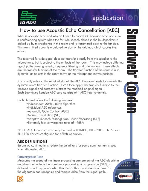
How to use <strong>Acoustic</strong> <strong>Echo</strong> <strong>Cancellation</strong> [AEC]<br />
What is acoustic echo and why do I need to cancel it? <strong>Acoustic</strong> echo occurs in<br />
a conferencing system when the far-side speech played in the loudspeakers is<br />
picked up by microphones in the room and is transmitted back to the far side.<br />
This transmitted signal is a delayed version of the original, which causes the<br />
echo.<br />
The received far-side signal does not transfer directly from the speaker to the<br />
microphone, but is subject to the artifacts of the room. This may include differing<br />
signal paths causing reverb, frequency filtering and attenuation. These effects<br />
are the transfer function of the room. The transfer function of the room is also<br />
dynamic, as objects in the room move or the microphone moves position.<br />
To correctly subtract the required signal, the AEC therefore needs to simulate the<br />
dynamic room transfer function. It can then apply that transfer function to the<br />
received signal and correctly subtract the modified original signal.<br />
Each Soundweb London AEC card consists of 4 AEC input channels.<br />
Each channel offers the following features:<br />
•Independent 20Hz - 8kHz algorithm<br />
•Individual AEC references<br />
•Automatic Gain Control (AGC)<br />
•Noise <strong>Cancellation</strong> (NC)<br />
•Adaptive (Speech Passing) Non-Linear Processing (NLP)<br />
•Extremely fast convergence rates of 49dB/s<br />
SoundwebTM London<br />
NOTE: AEC Input cards can only be used in BLU-800, BLU-320, BLU-160 or<br />
BLU-120 devices configured for 48kHz operation.<br />
AEC DEFINITIONS<br />
Before we continue let’s review the definitions for some common terms used<br />
when discussing AEC.<br />
Convergence Rate<br />
Measures the speed of the linear processing component of the AEC algorithm<br />
and does not include the non-linear processing or suppression (NLP) as<br />
dictated by industry standards. This means this is a measure of how fast<br />
the algorithm can recognize and remove echo from the signal path.<br />
1
How to use <strong>Acoustic</strong> <strong>Echo</strong> <strong>Cancellation</strong><br />
Double Talk<br />
Both far and near side speech are present.<br />
<strong>Echo</strong> Return Loss (ERL)<br />
This is a measure of the coupling between the AEC reference signal and the<br />
AEC input signal.<br />
<strong>Echo</strong> Return Loss Enhancement (ERLE)<br />
This shows the loss through the linear AEC algorithm (not including the non-linear<br />
processing.)<br />
Far Side (Reference)<br />
This is the remote side of the conference which will be heard from the near-side speakers.<br />
Gain Structure<br />
Proper gain structure will provide an adequate signal to noise ratio and reasonable<br />
headroom for an input signal.<br />
Near Side (Local)<br />
This is the local side of the conference where the echo canceller is located.<br />
Non-Linear Processing (NLP)<br />
The non-linear processing increases the power of the echo cancellation for difficult acoustic<br />
environments.<br />
Noise Cancelation (NC)<br />
Noise cancellation removes ambient noise from the AEC signal (e.g. computer fan noise).<br />
Voice Activity Detection (VAD)<br />
Detects whether the audio is speech or silence/background noise.<br />
AEC Card Control Panel<br />
The AEC default control panel is ordered in two groups of controls for every input channel.<br />
The first group of controls are identical to the standard Soundweb London input cards and<br />
function in the same manner. These controls are the audio input meter (configurable as Pre<br />
or Post-AEC), input meter controls - Attack, Release, Reference, and Phantom Power - for<br />
each input channel. The second group of controls are the AEC controls.<br />
2
How to use <strong>Acoustic</strong> <strong>Echo</strong> <strong>Cancellation</strong><br />
AEC Control Panel [Basic]<br />
The basic AEC control panel allows enabling and disabling of AEC<br />
and AGC, and allows setting levels for noise cancellation and nonlinear<br />
processing.<br />
AEC<br />
This button enables or disables AEC processing for each channel. When this button is<br />
enabled the AEC algorithm will remove the acoustic echo from the audio channel with linear<br />
processing and with a specified amount of non-linear processing. (See NLP Level below.)<br />
ERL Meter<br />
The <strong>Echo</strong> Return Loss (ERL) meter is a measure of the room’s natural attenuation of the<br />
far-side audio as it leaves the speaker(s) and re-enters the microphone(s). This parameter<br />
is controlled by proper gain structure setup (ensuring a good signal to noise ratio and<br />
reasonable headroom for the AEC input signal). A proper gain structure is critical for<br />
3
How to use <strong>Acoustic</strong> <strong>Echo</strong> <strong>Cancellation</strong><br />
distortion free sound and optimal performance for AEC. This is the<br />
single most important parameter when setting up the AEC system.<br />
The AEC algorithm will recognize and remove echo to its best extent when<br />
this meter is displaying in the ‘green’ range. The ‘green’ range is indicated on<br />
the control panel below 10dB. The algorithm will continue to converge over 10dB, but the<br />
convergence rate will decrease in that range.<br />
This meter will not update during double-talk. It is updated based on far-side speech only.<br />
ERLE Meter<br />
The <strong>Echo</strong> Return Loss Enhancement (ERLE) Meter measures how much acoustic echo is being<br />
removed from the signal path. This measurement consists of the natural room attenuation as<br />
indicated by the ERL meter and the amount of echo removed by the AEC algorithm. A lower<br />
signal indicates more echo being removed. The lower the meter, the better.<br />
NOTE: As dictated by industry standards, NLP contributions are not included in this reading.<br />
NLP contributions are made in addition to this meter’s reading.<br />
NLP Level<br />
The Non-Linear Processing (NLP) setting determines the amount of non-linear suppression<br />
that will be applied in conjunction with the AEC algorithm for each channel. NLP will remove<br />
the residual echo not removed by the linear part of the AEC algorithm.<br />
This parameter represents a trade-off between achieving good double-talk performance,<br />
with no suppression of the local speech signal, and very robust echo suppression, with no<br />
echo audible on the far side. At its most aggressive setting (NLP at 100%), the non-linear<br />
processing will remove any of the residual far-side echo picked up by the microphone.<br />
However, this is done with an increased risk that some of the near-side speech will be<br />
degraded as well, especially during double-talk. At its least aggressive setting (NLP at 0%),<br />
the non-linear processing is effectively disabled, which may let some echo through, but will<br />
allow for a more natural double-talk performance. The best setting for this parameter may<br />
depend on several factors, including the acoustic properties of the room and user preference.<br />
The default value of 50% may give a good balance between these two competing goals.<br />
NC Level<br />
The Noise-<strong>Cancellation</strong> (NC) setting will determine the amount of noise cancellation that<br />
will be applied to each channel. The noise cancellation algorithm is a very advanced<br />
algorithm that will remove steady-state noise without compromising the quality of speech<br />
4
How to use <strong>Acoustic</strong> <strong>Echo</strong> <strong>Cancellation</strong><br />
passing through the channel. This algorithm is great for removing<br />
projector noise, HVAC, and other unwanted background noise that<br />
can compromise speech intelligibility.<br />
AEC Control Panel [Advanced]<br />
The advanced panel gives access to controls for the Automatic Gain Control and Signal<br />
Threshold features.<br />
AGC<br />
The Automatic Gain Control is designed for voice applications.<br />
It is designed to compensate for varying distances between the<br />
speaker and their microphone as well as speech level variances<br />
at the near end. This provides the far end with a signal that will<br />
automatically be increased or decreased to maintain a consistent<br />
audio level. Setting the maximum gain too high can cause<br />
inconsistent gain structures and bring up the noise floor. The<br />
AGC will adjust the gain during near side speech only. This<br />
means that during pauses in near side speech, the noise floor will<br />
maintain a constant level, and will not grow to hit a target gain<br />
output. Only near side speech signals are used to control the<br />
gain.<br />
To use the AGC, first define target levels for the transmitted<br />
speech signal. The default target levels for AGC are a maximum<br />
of 6dBu and a minimum of -10dBu, which define a target<br />
window with 16dB of dynamic range. If the speech level is within<br />
the target window already, then the AGC-applied gain will go to<br />
0 dB.<br />
If the speech signal is below the target window (i.e., below the<br />
minimum target level), then the AGC will increase the gain (to a<br />
limit) so that the signal level meets the minimum target level. The<br />
AGC will limit the gain it can add to a signal by a maximum gain<br />
setting. Once the AGC has adjusted its gain high enough to<br />
meet the maximum gain setting, it will stop adding gain, even if<br />
the minimum target level is not reached.<br />
5
How to use <strong>Acoustic</strong> <strong>Echo</strong> <strong>Cancellation</strong><br />
This is useful to stop very weak speech signals, such as whispering,<br />
from driving the gain too high. Setting the maximum gain too high<br />
can cause inconsistent gain structures and bring up the noise floor.<br />
Similarly, if the level of the speech signal is higher than the maximum target<br />
level, then the AGC will reduce the gain, by as much as the minimum gain setting, in an<br />
attempt to bring the speech level down to the maximum target level.<br />
A generous range for the maximum gain and the minimum gain have been provided.<br />
Care should be taken, particularly with the maximum gain setting, to avoid extreme levels.<br />
Situations where the maximum gain setting should be set over 10dB will be rare. The<br />
maximum gain setting has the potential to break a gain structure, so set it carefully, especially<br />
if the setting is to be used over 10dB.<br />
The attack and release rates for the AGC describe how fast it will adjust its gain. Because<br />
the AGC only adjusts gain during near-side speech signals (and not during unvoiced<br />
consonants like t, s, p, and f), the attack and release rates should be set higher than other<br />
typical AGC implementations.<br />
The AGC meter shows the current amount of gain being applied to the signal.<br />
Signal Threshold<br />
In a conferencing system, some microphones may have a mute or push-to-talk feature built<br />
in. If a mic goes into or comes out of mute, then the characteristics of the conferencing<br />
system change instantly, and echo may leak through as the AEC re-converges. A signal<br />
threshold is defined to allow mics with mute or push-to-talk features to work seamlessly with<br />
AEC. Using the threshold, a level can be defined that is below the normal, ambient noise<br />
floor of the room. If the mic level goes below this level, then the AEC algorithm will treat<br />
the microphone as muted, and minimize any echo that would have occurred otherwise. The<br />
“Active” LED indicates that the microphone level is over the threshold, and the mic is not<br />
treated as being muted. When the LED is off, the mic level is below the threshold, and the<br />
mic will be treated as being muted.<br />
6
How to use <strong>Acoustic</strong> <strong>Echo</strong> <strong>Cancellation</strong><br />
To set the threshold:<br />
•Put the microphone in its muted mode.<br />
•Set the threshold to a level where the LED turns itself on and off<br />
randomly.<br />
•Raise the threshold from this level by 3 to 6 dB. The LED should now be off with no<br />
flickering.<br />
•Take the microphone out of its muted mode and the LED should illuminate.<br />
This process may need to be repeated if the microphone’s preamp gain is adjusted. To<br />
disable the mute feature based on signal threshold, simply set the threshold to its minimum<br />
value.<br />
London Architect Configuration Symbol<br />
For each recognized AEC card in a Soundweb London unit the following configuration<br />
symbols will appear in the Default Configuration view:<br />
The left hand ‘AEC Input Card’ block functions like a<br />
standard Soundweb London input card. This block contains<br />
the 4 channels of processed AEC audio as well as the 4<br />
channels of ‘dry’ (unprocessed) input audio being fed into<br />
the Soundweb London AEC card. The right hand block<br />
‘AEC Input Ref (REFERENCE) Return’ is used to provide the<br />
REFERENCE signal for each AEC algorithm. The Reference<br />
signal is the signal that will be removed by the AEC algorithm from the signal path. The<br />
Reference signal should be taken from as close to the output as possible. This will provide<br />
the AEC algorithm with the most accurate representation of the signal (to be cancelled) and<br />
will provide the best AEC performance.<br />
7
How to use <strong>Acoustic</strong> <strong>Echo</strong> <strong>Cancellation</strong><br />
Example: Basic Conferencing without Local Sound<br />
Reinforcement<br />
Local Sound Reinforcement refers to a design where the local<br />
microphones feed both the far-side and the local room speakers. This<br />
typically applies in large rooms where other participants located in the same room can’t hear<br />
the person speaking.<br />
This example shows 4 microphones feeding the local audio to the far-side via a ‘Telephone<br />
Hybrid’. The far side audio is received via the ‘Telephone Hybrid’ and processed by the<br />
London’s Low Pass, High Pass, and Parametric EQ’s before being sent to the local room’s<br />
speaker(s) for the local participants to hear. Once the far-side audio leaves the local-side’s<br />
speakers the signal will bounce around the room, re-enter the local microphone (mixing with<br />
the local side’s speech), and the far-side signal will be sent back to the far-side resulting in<br />
‘echo’. To prevent this echo, the far-side signal is sent to the Reference inputs of the AEC<br />
card where the AEC algorithm will compare this signal with the input signals of the AEC card<br />
(the microphones) and remove the Reference signal (far side signal) from the input signal<br />
path resulting in only the local side audio being sent to the far-side i.e. no echo.<br />
The image below is the same design with the Reference signal wired incorrectly. Because the<br />
Reference is taken before the room processing blocks, the AEC algorithm will not understand<br />
that certain frequencies were cut/boosted intentionally and will not be able to model the<br />
room to its full ability.<br />
8
How to use <strong>Acoustic</strong> <strong>Echo</strong> <strong>Cancellation</strong><br />
Example: Basic Conferencing with Local Sound Reinforcement<br />
This example shows 4 microphones feeding the audio to the far side via<br />
a ‘Telephone Hybrid’ as well as feeding the local speakers for local sound<br />
reinforcement. Signal mixing is performed using the Gated Automixer processing object.<br />
The best method for this type of design incorporates a mix-minus setup to maintain proper<br />
gain structure, and to prevent the speaker directly above the person talking from transmitting<br />
a - room-colored - copy that will re-enter the open microphone and be transmitted to the far<br />
side along with the original voice signal.<br />
The design below shows both the far side and near side signals feeding the local room<br />
speakers. This design works, but as explained above, since the Reference signal is not being<br />
fed after the room processing blocks (as close to the speaker output as possible) the AEC<br />
algorithm won’t perform to its full potential.<br />
If the Reference is moved to the same location as in the previous ‘No Reinforcement’<br />
example, it will satisfy the rule of placing the Reference ‘as close as possible’ to the speaker<br />
output, but in doing so the Reference will be fed with a mix of both the near side and far side<br />
signals. Since the Reference signal is the ‘signal we want to remove from the input audio<br />
path’ then this means that the AEC algorithm will cancel the speaker’s voice coming into the<br />
AEC Input Card. Since the input microphone signal path is being fed to the far side as well<br />
as the local speakers then the far side will not be able to hear the speaker either. (Typically<br />
what happens is that only portions of the speaker’s voice gets cancelled because of the VAD<br />
state and it causes the voice to distort and sound bad to both the far side and the near side)<br />
9
How to use <strong>Acoustic</strong> <strong>Echo</strong> <strong>Cancellation</strong><br />
To solve this dilemma utilize an N-input parametric EQ and another set of High/Low Pass<br />
objects in order to provide the Reference the same signal as the room speaker. This means<br />
that you only Reference (remove) the far side signal while still feeding a mix of both near side<br />
and far side audio to the room speakers. It is very important to make sure the same<br />
settings are maintained in both signal paths. In particular, care must be taken that<br />
any non-linear processing (such as compression or limiting) that happens to the<br />
speaker output signal, also happens to the Reference signal. <strong>BSS</strong> <strong>Audio</strong> recommend<br />
using the ‘copy parameter values’ feature to ensure the settings are identical.<br />
10
How to use <strong>Acoustic</strong> <strong>Echo</strong> <strong>Cancellation</strong><br />
Example: Local Media Distribution<br />
Add to the previous Local Sound Reinforcement design by adding a<br />
local DVD player and a local PC audio input for presentations that the<br />
near side would like to share with the far side as well as having the near side<br />
speakers distribute this material.<br />
This design requires that the local media inputs (DVD/PC) are sent directly to the far side via<br />
a ‘Telephone Hybrid’ to provide a high quality audio signal. For the near side to hear the<br />
local media inputs through their speakers, Reference (remove) the far side signal and local<br />
media signal from the microphone input signal path to prevent the far side from hearing<br />
their own voice (echo) and from getting a lower quality local media signal - which can be<br />
interpreted as an echo as well. Remember that you are already directly sending the local<br />
media signal to the far side so you need to make sure that the local media signal is not<br />
allowed to travel to the far side via the microphone input signal path as well.<br />
Once again, it should be emphasized that the ERL meter needs to be in the ‘green’ zone<br />
while the local Media sources are playing during the conference or the AEC algorithm will<br />
not optimally remove the echoes.<br />
11
How to use <strong>Acoustic</strong> <strong>Echo</strong> <strong>Cancellation</strong><br />
This page intentionally blank<br />
12