ILA Series User Manual - QSC Audio Products
ILA Series User Manual - QSC Audio Products
ILA Series User Manual - QSC Audio Products

You also want an ePaper? Increase the reach of your titles
YUMPU automatically turns print PDFs into web optimized ePapers that Google loves.
Rigging the Installation Line Array (continued)<br />
Table 1: <strong>ILA</strong> Working Load Limits<br />
Component Weight 7:1 Design Factor 10:1 Design Factor 12:1 Design Factor<br />
EB2082-i Extension Bar 38 lb (17.3 kg) 1714 lb (779.2 kg) 1200 lb (545.5 kg) 1000 lb (454.5 kg)<br />
FB2082-i Array Frame 17 lb (7.7 kg) 740 lb (336.4 kg) 518 lb (235.5 kg) 432 lb (196.2 kg)<br />
PB2082-i Pull Back Bar 6 lb (2.7 kg) 423 lb (192.2 kg) 296 lb (134.5 kg) 247 lb (112.1 kg)<br />
WL2082-i Loudspeaker 37 lb (16.8 kg) 634 lb (288.3 kg) 445 lb (201.8 kg) 371lb (168.6 kg)<br />
WL115-sw Loudspeaker 111 lb (50.5 kg) 740 lb (336.4 kg) 518 lb (235.5 kg) 432 lb (196.2 kg)<br />
M8 Shoulder Bolt 1 not applicable 1003 lb (455.8 kg) 702 lb (319.1 kg) 585 lb (265.9 kg)<br />
M8 Ball-lock Pin 1 not applicable 1810 lb (822.7 kg) 1267 lb (575.9 kg) 1056 lb (479.9 kg)<br />
M8 Locking Plate 1 not applicable 1286 lb (584.4 kg) 900 lb (409.1 kg) 750 lb (340.9 kg)<br />
M12 Shoulder Bolt 1 not applicable 4744 lb (2156.3 kg) 3321 lb (1509.4 kg) 2767 lb (1257.8 kg)<br />
3/8” Fastener 1 not applicable 1943 lb (883.4 kg) 1360 lb (618.4 kg) 1134 lb (515.3 kg)<br />
7/8” Fastener 1 not applicable 8110 lb (3686.4 kg) 5677 lb (2580.5 kg) 4731 lb (2150.4 kg)<br />
1- Working Load Limits are per fastener loaded in double shear. Data is for informational purposes only.<br />
Attaching WL2082-i to Array Frame<br />
Before beginning any installation, have your system designer configure the array with proper<br />
splay angles using <strong>QSC</strong>’s EASE Focus (Array Calculator). All orientation of product is to be as<br />
viewed from the rear of the enclosure.<br />
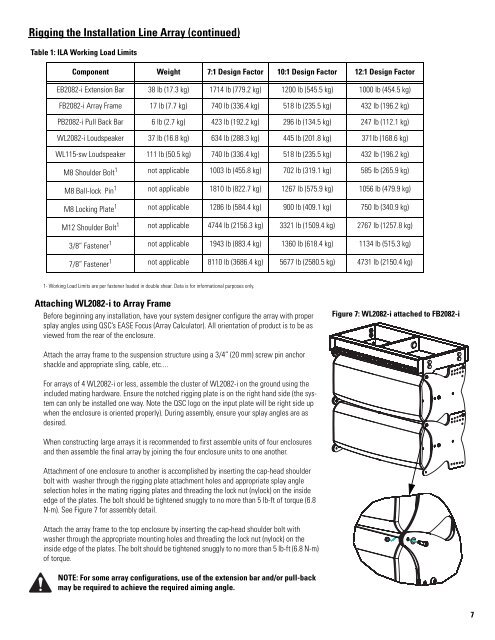
Figure 7: WL2082-i attached to FB2082-i<br />
Attach the array frame to the suspension structure using a 3/4” (20 mm) screw pin anchor<br />
shackle and appropriate sling, cable, etc....<br />
For arrays of 4 WL2082-i or less, assemble the cluster of WL2082-i on the ground using the<br />
included mating hardware. Ensure the notched rigging plate is on the right hand side (the system<br />
can only be installed one way. Note the <strong>QSC</strong> logo on the input plate will be right side up<br />
when the enclosure is oriented properly). During assembly, ensure your splay angles are as<br />
desired.<br />
When constructing large arrays it is recommended to first assemble units of four enclosures<br />
and then assemble the final array by joining the four enclosure units to one another.<br />
Attachment of one enclosure to another is accomplished by inserting the cap-head shoulder<br />
bolt with washer through the rigging plate attachment holes and appropriate splay angle<br />
selection holes in the mating rigging plates and threading the lock nut (nylock) on the inside<br />
edge of the plates. The bolt should be tightened snuggly to no more than 5 lb-ft of torque (6.8<br />
N-m). See Figure 7 for assembly detail.<br />
Attach the array frame to the top enclosure by inserting the cap-head shoulder bolt with<br />
washer through the appropriate mounting holes and threading the lock nut (nylock) on the<br />
inside edge of the plates. The bolt should be tightened snuggly to no more than 5 lb-ft (6.8 N-m)<br />
of torque.<br />
NOTE: For some array configurations, use of the extension bar and/or pull-back<br />
may be required to achieve the required aiming angle.<br />
7