You also want an ePaper? Increase the reach of your titles
YUMPU automatically turns print PDFs into web optimized ePapers that Google loves.
<strong>BASIS</strong> <strong>922uz</strong><br />
8x8 CobraNet Enabled Control and Monitoring Signal Processor<br />
Hardware Manual<br />
*TD-000197-00*<br />
TD-000197-00 rev.A
IMPORTANT SAFETY PRECAUTIONS & EXPLANATION OF SYMBOLS<br />
The lightning flash with arrowhead symbol within an equilateral triangle is intended to alert the user to<br />
the presence of uninsulated “dangerous” voltage within the product’s enclosure that may be of sufficient<br />
magnitude to constitute a risk of electric shock to humans.<br />
The exclamation point within an equilateral triangle is intended to alert the user to the presence of<br />
important operating and maintenance (servicing) instructions in this manual.<br />
SAFEGAURDS<br />
Electrical energy can perform many useful functions. This unit has been engineered and manufactured to<br />
assure your personal safety. Improper use can result in potential electrical shock or fire hazards. In order<br />
not to defeat the safeguards, observe the following instructions for its installation, use and servicing.<br />
CAUTION: To reduce the risk of electric shock, do not remove the cover. No user-serviceable parts inside.<br />
Refer servicing to qualified service personnel.<br />
WARNING: To prevent fire or electric shock, do not expose this equipment to rain or moisture.<br />
1- Maximum operating ambient temperature is 50°C (122°F).<br />
2- Never restrict airflow through the device fan or vents. Please insure that the air intake and exhaust<br />
vents are unobstructed.<br />
3- When installing equipment into rack, distribute the units evenly. Otherwise, hazardous conditions<br />
could be created by an uneven weight distribution.<br />
4- Connect the unit only to a properly rated supply circuit. The <strong>BASIS</strong> <strong>922uz</strong> is suitable for connection to<br />
100 - 240 VAC, 47 - 440 hertz, with no special considerations other than the appropriate IEC power cord.<br />
5- Reliable Earthing (Grounding) of rack-mounted equipment should be maintained.<br />
LITHIUM BATTERY WARNING<br />
THIS EQUIPMENT CONTAINS A NON-RECHARGEABLE LITHIUM BATTERY. LITHIUM IS A CHEMICAL<br />
KNOWN TO THE STATE OF CALIFORNIA TO CAUSE CANCER OR BIRTH DEFECTS. THE NON-RECHARGE-<br />
ABLE LITHIUM BATTERY CONTAINED IN THIS EQUIPMENT MAY EXPLODE IF IT IS EXPOSED TO FIRE OR<br />
EXTREME HEAT. DO NOT SHORT CIRCUIT THE BATTERY. DO NOT ATTEMPT TO RECHARGE THE NON-<br />
RECHARGEABLE LITHIUM BATTERY.<br />
FCC INTERFERENCE STATEMENT<br />
NOTE: This equipment has been tested and found to comply with the limits for a class B digital device,<br />
pursuant to part 15 of the FCC rules. These limits are designed to provide reasonable protection against<br />
harmful interference in a residential installation. This equipment generates, uses, and can radiate radio<br />
frequency energy and if not installed and used in accordance to the instructions, may cause harmful<br />
interference to radio communications. However, there is no guarantee that interference will not occur in<br />
a particular installation. If this equipment does cause harmful interference to radio or television reception,<br />
which can be determined by switching the equipment off and on, the user is encouraged to try to<br />
correct the interference by one or more of the following measures:<br />
- Reorient or relocate the receiving antenna.<br />
- Increase the separation between the equipment and the receiver.<br />
- Connect the equipment into an outlet on a circuit different from that to which the receiver is connected.<br />
- Consult the dealer or an experienced radio or TV technician for help.<br />
2<br />
© Copyright 2005 <strong>QSC</strong> <strong>Audio</strong> <strong>Products</strong>, Inc. <strong>QSC</strong>® is a registered trademark of <strong>QSC</strong> <strong>Audio</strong> <strong>Products</strong>, Inc. “<strong>QSC</strong>” and the <strong>QSC</strong> logo are registered<br />
with the U.S. Patent and Trademark Office. All trademarks are the property of their respective owners.
Don’t want to read the entire manual? Just<br />
want to dig right in? Go to page 18....<br />
Introduction<br />
The <strong>BASIS</strong> <strong>922uz</strong> provides the digital audio transport, signal<br />
processing, control and status monitoring facilities needed<br />
to bind a group of amplifiers and loudspeakers into an integrated<br />
functioning system. In conjunction with <strong>QSC</strong>ontrol.net<br />
software, the <strong>BASIS</strong> <strong>922uz</strong> enables the user to<br />
design, test and deploy professional audio reinforcement<br />
and distribution systems ranging in size from one to hundreds<br />
of channels.<br />
Each <strong>QSC</strong> power amplifier connects directly to a <strong>BASIS</strong><br />
<strong>922uz</strong> via one of its four <strong>QSC</strong> DataPorts. All mission-critical<br />
elements of the <strong>BASIS</strong>-driven sound system are monitored.<br />
User-selected events are logged and loudspeaker protection<br />
features unique to <strong>BASIS</strong> such as <strong>QSC</strong>'s power limiter are<br />
made possible through the DataPort functionality.<br />
A standard Windows computer is the principle user-interface<br />
for controlling the overall <strong>BASIS</strong>/<strong>QSC</strong>ontrol system.<br />
However, the <strong>BASIS</strong> <strong>922uz</strong> also offers a front panel interface<br />
for accessing a few critical functions.<br />
A single <strong>QSC</strong>ontrol.net server computer can support several<br />
clients running <strong>QSC</strong>'s latest Venue Manager software. Thus,<br />
the sound system can be operated via several computers,<br />
roaming wireless laptops, tablets, etc., all at the same time,<br />
from anywhere a connection to the <strong>QSC</strong>ontrol.net network<br />
is available.<br />
The <strong>QSC</strong>ontrol.net network can also be managed from a single<br />
computer running both the client and the server. Once all<br />
<strong>BASIS</strong> devices in a system are configured, a computer is no<br />
longer required on that system’s network. All basic functions<br />
of the <strong>BASIS</strong> <strong>922uz</strong> continue to operate with or without<br />
a control computer connected to the network.<br />
The configurable DSP engine provides all of the functions<br />
of a signal chain, such as very flexible and precise crossovers,<br />
delays, equalization, compression/limiting, etc.<br />
<strong>Audio</strong> enters a <strong>BASIS</strong> <strong>922uz</strong> either through analog universal<br />
inputs (mic to line level with software-selectable +48V<br />
phantom power) or from CobraNet source devices such as<br />
<strong>QSC</strong>'s line of RAVE digital audio routers. Any combination of<br />
16 CobraNet channels (selected from up to 4 bundles of 32<br />
channels) can be routed into the 24 x 24 DSP engine. Any or<br />
all of the 24 DSP channels can also be routed to up to 32<br />
CobraNet channels on the network.<br />
Unlike other configurable DSP boxes, the intrinsic processing<br />
latency of the <strong>BASIS</strong> <strong>922uz</strong> is both short and fixed at<br />
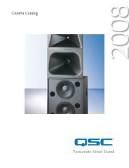
1- Power indicator<br />
2- Diagnostic indicator<br />
3- Network status indicators<br />
4- Port connection status indicators<br />
5- Signal presence/clip indicators<br />
6- Multi-function push buttons<br />
7- Display<br />
8- Rotary select/accept knob<br />
9- Safe mode switch (recessed)<br />
10- DataPorts<br />
11- Mic/line inputs<br />
12- Monitor chain in/out<br />
13- Relay outputs<br />
14- Logic outputs<br />
15- Omni inputs<br />
16- RS-232 port<br />
17- Network status indicators<br />
18- <strong>QSC</strong>ontrol 10BaseT receptacle<br />
19- CobraNet 100BaseT receptacle<br />
20- IEC power inlet<br />
See page 14 for detailed descriptions.<br />
3
Introduction (continued)<br />
0.396 milliseconds. When analog input and analog outputs<br />
are used, the total delay is 2.354 milliseconds. The delay<br />
does not change regardless of the DSP configuration, unless<br />
the configuration intentionally adds more delay.<br />
The <strong>BASIS</strong> <strong>922uz</strong> also supports the new optional lowlatency<br />
CobraNet feature that provides transport at only<br />
2.66 milliseconds delay. Thus the delay from analog to analog<br />
across the network can be less than 6 milliseconds, fast<br />
enough not only for large audio distribution but for the most<br />
critical real-time live performance work.<br />
Both software and firmware can be easily updated over the<br />
network. In the future, <strong>QSC</strong> will be adding new capabilities<br />
to both <strong>BASIS</strong> and <strong>QSC</strong>ontrol.net. Our latest code releases<br />
and access to up-to-date information on <strong>BASIS</strong> and <strong>QSC</strong>ontrol.net<br />
are available at www.qscontrol.net. We invite you<br />
to visit us there.<br />
We've applied our many years of experience in supporting<br />
high-end installed sound with our previous system-building<br />
products such as RAVE, <strong>QSC</strong>ontrol, CM16a, DSP-3, DSP-4,<br />
and DSP-30. The <strong>BASIS</strong> <strong>922uz</strong> brings all that technology<br />
together in one compact, powerful, easy to use system. We<br />
are confident that your new <strong>BASIS</strong> <strong>922uz</strong> will provide years<br />
of dependable service and we hope it will help you, the system<br />
designer and implementer, to express your creative<br />
audio system ideas.<br />
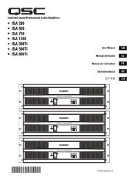
Block Diagram<br />
4
Introduction - Networking the <strong>BASIS</strong> <strong>922uz</strong><br />
The <strong>BASIS</strong> <strong>922uz</strong> has two RJ-45 network connection ports on the rear panel. One port is labeled "<strong>QSC</strong>ontrol" and supports standard<br />
10BASE-T Ethernet. The other port is labeled "CobraNet" and supports 100BASE-TX, also known as "Fast Ethernet". In the following<br />
sections we describe the use of these ports and show example network connection schemes.<br />
The <strong>BASIS</strong> <strong>922uz</strong> supports two distinct kinds of network activity; the first is audio transport via CobraNet, and the second is control and<br />
monitoring via <strong>QSC</strong>ontrol.net. The user can choose to install one network for CobraNet traffic and a second separate network for<br />
<strong>QSC</strong>ontrol.net traffic. We call this the "Two Wire Interface". Alternately, it is possible to run both control and audio traffic over Cobra-<br />
Net via the CobraNet port. In this case the <strong>QSC</strong>ontrol port is unused. We call this the "Single Wire Interface".<br />
Under the most demanding real-time control conditions and when using the lowest latency CobraNet settings, users may experience<br />
better <strong>QSC</strong>ontrol.net performance using separate networks, especially when displaying a great many real-time meters. For most applications,<br />
separate networks won't provide any discernible benefits and will cost more. We therefore recommend using the Single Wire<br />
Interface when running CobraNet.<br />
If your application uses only analog I/O without CobraNet, then you should use the <strong>QSC</strong>ontrol port for <strong>QSC</strong>ontrol.net traffic and ignore<br />
the CobraNet port.<br />
Why CobraNet Needs Special Treatment:<br />
Ordinary Ethernet traffic has no guaranteed time of delivery. Packets of information may arrive at their destination out of order and<br />
some may be delayed more than others. This is fine for E-mail and even for downloading MP3 files over the Internet. Everything ends up<br />
properly reassembled at the destination, but how long this takes will vary according to network loading, span, etc. In contrast, Cobra-<br />
Net is "real time" - it delivers audio with a minimal, consistent transmission delay. CobraNet is designed to use as much of conventional<br />
networking technology as possible while providing both guaranteed time of delivery and isochronicity - maintaining a phase-locked<br />
sample-accurate clock across the entire network. These requirements mean that ordinary unregulated Ethernet data cannot be freely<br />
mixed with CobraNet information. The two can coexist on the same wire, but only by adhering to the proper rules.<br />
To learn more about CobraNet and appropriate network topologies, please visit http://www.qscaudio.com/products/network/<br />
resources.htm and http://www.peakaudio.com/CobraNet/background.html.<br />
Notes on Network Systems Design:<br />
As with any communications system, the reliability and performance of a local area network is intimately related to the designer's skill<br />
and knowledge in implementing a topology that is robust, efficient and standards-compliant. Proper network design is even more critical<br />
in distributed multimedia systems. Therefore, it is important for the system designer to realize that some conventional network<br />
practices must be avoided. Although each network design is unique and may carry its own performance requirements, compliance to<br />
the following three points will assist in building an audio network that is trouble free and efficient.<br />
First, audio and conventional data communications deliveries should not exist on the same LAN or VLAN. The exception to this is the<br />
<strong>BASIS</strong> <strong>922uz</strong> Single Wire Interface, which offers a solution for converging audio and <strong>QSC</strong>ontrol.net onto the same LAN or VLAN. However,<br />
conventional communications, such as corporate networks, print services, e-mail and Internet access, should not exist alongside<br />
CobraNet audio and <strong>QSC</strong>ontrol.net on the same LAN or VLAN. Further, CobraNet audio and <strong>QSC</strong>ontrol.net data should not exist<br />
together on the same LAN or VLAN when implementing the Two Wire Interface. This is not to say that conventional communications<br />
cannot share the same network hardware with a <strong>BASIS</strong> <strong>922uz</strong>. In fact, common network hardware, such as managed Ethernet switches<br />
and media converters, can service both <strong>BASIS</strong> <strong>922uz</strong> products and conventional data communications equipment so long as the managed<br />
switch or media converter are partitioned into separate network domains. This is normally done by configuring a separate VLAN<br />
for each data type. (Some switches may allow individual port assignments or support partitions through DIP switch selection.)<br />
Second, CobraNet audio must traverse either a repeater domain or a network switch domain. The point here is that the CobraNet port<br />
on a <strong>BASIS</strong> <strong>922uz</strong> must connect directly to, and only to, either a repeater LAN or a switched Ethernet LAN. Hybrid networks containing<br />
both repeaters and switches are not permitted on the audio segment. Connecting the CobraNet port to a repeater that is in turn connected<br />
to a network switch poses an illegal and non-compliant condition. We recommend always connecting the <strong>QSC</strong>ontrol and/or<br />
CobraNet port(s) directly to network switch ports.<br />
5
Third, the <strong>BASIS</strong> <strong>922uz</strong> and <strong>QSC</strong>ontrol.net system are targeted at network switch deployments. The consumer costs of Ethernet<br />
switches have continued to fall over the last several years and are now comparable with repeaters on a per port basis. In addition, the<br />
sophistication and scalability of network switches make them ideal for new installations. However, we do realize that designers may<br />
wish to add <strong>BASIS</strong> products to existing audio network installations that are built on repeater LAN topologies. This applies primarily to<br />
existing CM16a and RAVE networks. For this very reason we continue to support connectivity to network repeater hardware with the<br />
<strong>BASIS</strong> <strong>922uz</strong>. Support for network repeaters exists only with the Two Wire Interface and only with the standard CobraNet forwarding<br />
latency. That is to say that the <strong>QSC</strong>ontrol port and the CobraNet port must be connected to separate repeater LANs. Even when properly<br />
configured, audio channel capacity is severely limited and both audio and control network expansion is limited by the respective capacity<br />
of each segment. In other words, scalability ceases to exist when bandwidth demands on the <strong>QSC</strong>ontrol.net segment approach 10<br />
Mbps and demand on the CobraNet segment approaches 100 Mbps. Obviously, we recommend taking advantage of switch network<br />
technology whenever possible.<br />
It should be noted here that while the CobraNet port on a <strong>BASIS</strong> <strong>922uz</strong> is restricted to repeater LAN or switch LAN deployments,<br />
<strong>QSC</strong>ontrol.net is a TCP/IP standards-compliant network system and therefore supports operation on network repeaters, switches and<br />
routers. When implementing the Two Wire Interface, the <strong>QSC</strong>ontrol.net segment does not require a single topology data path and<br />
therefore repeaters, switches and routers may be assembled on the LAN in a hybrid fashion.<br />
To learn more about network design rules and system compliance visit the <strong>QSC</strong> network resources page at http://www.qscaudio.com/<br />
products/network/resources.htm. To learn more about CobraNet design requirements and to obtain the CobraCAD system design utility<br />
visit the Peak <strong>Audio</strong> website at http://www.peakaudio.com/CobraNet/Network_Design.html.<br />
All of this may seem daunting if you are new to networking. However, it all boils down to connecting a few simple cables between various<br />
networking devices. Most of the time it "just works". <strong>QSC</strong> helped pioneer CobraNet with our RAVE products and there are hundreds<br />
of installations all over the world, in theme parks, hotels, stadiums - everywhere. They run hum-free, sound great and are very<br />
reliable.<br />
The following examples will help get you started, but they just scratch the surface of what can be achieved with advanced networking…<br />
Example #1 - <strong>QSC</strong>ontrol.net X-over mode:<br />
This is the simplest connection you can make between the <strong>BASIS</strong> <strong>922uz</strong> and your computer. Use a CAT-5 crossover cable connected<br />
between the <strong>BASIS</strong> <strong>QSC</strong>ontrol port and your computer's Network Interface Card, (NIC). No network switch is required. With <strong>QSC</strong>ontrol.net<br />
server and client software installed and running on your computer you will be able to completely set up and monitor your <strong>BASIS</strong><br />
<strong>922uz</strong>.<br />
6
Example #2 - CobraNet X-over mode:<br />
This is the simplest connection you can make between two <strong>BASIS</strong> boxes. Use a CAT-5 crossover cable connected between the Cobra-<br />
Net ports of each unit. No network switch is required. This connection allows audio to pass between the two <strong>BASIS</strong> boxes over Cobra-<br />
Net.<br />
Combining example 1 and 2 lets you setup and monitor one box at a time, much as you would have to do using a point-to-point RS232<br />
connection, while passing audio between them, all without a network switch. However, you would have to physically connect your<br />
computer first to one <strong>BASIS</strong> box and then to the other. With this elementary connection you don't have a true network. It is just like<br />
making RS-232 connections - except that performance is much better.<br />
All the other examples are of proper networks and all require a network switch. On a proper network, you have direct access to all<br />
<strong>BASIS</strong> products all of the time without having to physically switch between them. You still get the great performance of TCP/IP over<br />
Ethernet. (And we believe <strong>QSC</strong>'s advanced 4th generation networking software provides the best performance of any networked<br />
audio control system available today including Ethernet based systems from competitors.)<br />
7
8<br />
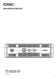
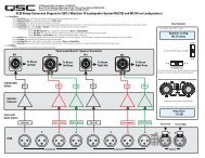
Example #3 - Single Wire Interface:<br />
Here all <strong>QSC</strong>ontrol.net and CobraNet traffic shares the same single CAT-5 cable between the <strong>BASIS</strong> <strong>922uz</strong> and an unmanaged Ethernet<br />
switch. The <strong>QSC</strong>ontrol.net system manages traffic flow efficiently and reliably so that all audio and control data is delivered to its<br />
appropriate destination anywhere on the network. Though the example shows only two <strong>BASIS</strong> <strong>922uz</strong> units, as many devices may be<br />
connected as there are available switch ports. All <strong>BASIS</strong> units will be able to communicate simultaneously with the computer. All will<br />
have CobraNet audio. Switches can be connected to other switches to build larger networks; all of the normal networking principles<br />
apply. (Note: there must be at least two CobraNet devices online for any data - audio or control - to come out of the CobraNet port.)
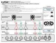
Example #4 - Two-Wire Interface (shared network hardware):<br />
This example illustrates the Two-Wire Interface with a managed Ethernet switch. The switch is configured with multiple virtual<br />
local area networks (VLANs). Ethernet deliveries can only reach destination ports belonging to the same VLAN from which it was<br />
sourced. The figure shows a separate VLAN for <strong>QSC</strong>ontrol.net traffic and a separate VLAN for CobraNet audio traffic. This configuration<br />
essentially provides a dedicated network for <strong>BASIS</strong> <strong>922uz</strong> control and monitoring (including the system controller) and a<br />
second dedicated network for CobraNet audio. As with the previous example, as many <strong>BASIS</strong> <strong>922uz</strong> units may be connected as<br />
there are switch ports available. All <strong>BASIS</strong> units will be able to communicate with the computer. All will have CobraNet audio.<br />
Switches can be connected to other switches to build larger networks; all of the normal networking principles apply.<br />
9
10<br />
Example #5 - Two-Wire Interface (separate network hardware):<br />
Example #5 is conceptually similar to example #4. The difference here is that separate networks are created by providing each local<br />
area network (LAN) with its own network switch. Therefore, traffic segmentation is physical rather than logical. Example #5 also provides<br />
an additional level of fault tolerance, although at the expense of additional network hardware. The figure shows a separate network<br />
switch for <strong>QSC</strong>ontrol.net traffic and a separate network switch for CobraNet audio traffic. All of the previous comments regarding<br />
network expansion still apply.
Unpacking<br />
There are no special unpacking precautions. However, it is recommended you keep the original packing material for reuse in the rare<br />
event that service be required. If service is required and the original packing material is not available, ensure that the unit is adequately<br />
protected for shipment (strong box of appropriate size, sufficient packing material to prevent load-shifting or impact damage) or call<br />
<strong>QSC</strong>’s Technical Services Department for packing material and a carton.<br />
What is included in the carton:<br />
Item Description Quantity<br />
1 <strong>BASIS</strong> <strong>922uz</strong> 1<br />
2 Self-adhesive rubber feet 4<br />
3 Hardware Manual (this document) 1<br />
4 <strong>QSC</strong>ontrol.net Software CD 1<br />
5 IEC Power Cord 3 x #18 AWG 1<br />
6 3-pin terminal block connector 10<br />
7 2-pin terminal block connector 10<br />
8 5-pin terminal block connector 1<br />
Mounting<br />
The <strong>BASIS</strong> <strong>922uz</strong> can be used in or out of an equipment rack. Rack mounting is optional. Adhesive rubber feet are included for non-rack<br />
mount installations. Use them to prevent the unit from scratching or marring support surfaces.<br />
Rack Mounting<br />
Rack mount the <strong>BASIS</strong> <strong>922uz</strong> by supporting it from underneath while aligning the mounting holes with the threaded screw holes in the<br />
rails; install all four mounting screws and washers and tighten securely. Ensure use of all four mounting screws in order to minimize the<br />
chance of bending or distorting the rack mount ears. If the <strong>BASIS</strong> <strong>922uz</strong> is to be transported while in a rack, we recommend supporting<br />
the rear of the chassis. This will help prevent the unit from being damaged from the increased mechanical stresses of portable and<br />
mobile use. The <strong>BASIS</strong> <strong>922uz</strong>’s chassis includes integral rear mounting tabs for securing to the rack mounting ears.<br />
Be certain not to<br />
block the cooling air<br />
ventilation openings<br />
on the sides of the<br />
chassis.<br />
Be certain not to block<br />
the cooling air ventilation<br />
openings on the<br />
sides of the chassis.<br />
11
Computer Requirements & Software Installation<br />
Installing <strong>QSC</strong>ontrol.net is easy. All you need to do is choose the folder where the program is to be stored (the default setting is acceptable<br />
for most applications). We recommend your system meet the following minimum requirements:<br />
1- IBM PC compatible computer with a Pentium 4 processor.<br />
2- Processor speed of 1 GHz (2 GHz or faster recommended for systems with 30 or more <strong>BASIS</strong>/RAVE/DSP units).<br />
3- 512 megabytes of RAM (1 gigabyte recommended for systems with 30 or more <strong>BASIS</strong>/RAVE/DSP units).<br />
4- Hard drive with at least 500 MB of free space for the program and files you generate.<br />
5- Display resolution of 1024 X 768, 16-bit color.<br />
6- CD-ROM drive to install the software.<br />
7- 10BaseT/100BaseTx network interface card<br />
8- Windows XP Professional, XP Home, Windows 2000 SP2 (or better), or Windows NT4.0 SP6a operating system. Windows 95,<br />
98 and ME platforms are not supported.<br />
Note: If system is used for real-time adjustments and configuration of audio systems, we recommend all Windows Power Options<br />
(located in the Windows Control Panel) features be disabled. Display, hard drive, system standby and hibernation settings should be set<br />
to “Never”. This avoids waiting for the system to “wake-up” if adjustment is needed after an elapsed period of time.<br />
To Install <strong>QSC</strong>ontrol.net:<br />
1- Start your computer and start Windows.<br />
2- If there are any programs running, please close them now. Be sure to leave Windows running.<br />
3- Place the <strong>QSC</strong>ontrol.net CD-ROM in your CD-ROM drive. You can also select Start-Run and browse for the file named setup.exe<br />
from the CD.<br />
4- Click the Install <strong>QSC</strong>ontrol.net button.<br />
5- Follow the installation instructions on the screen.<br />
To Uninstall <strong>QSC</strong>ontrol.net:<br />
1- Click the Start menu button and choose Settings/Control Panel.<br />
2- Double-click the Add/Remove Program icon.<br />
3- Select <strong>QSC</strong>ontrol.net from the list, then click Add/Remove.<br />
4- Click Yes to confirm you would like to uninstall <strong>QSC</strong>ontrol.net.<br />
12
General Information & Configuration Memories<br />
Amplifier Setup<br />
The <strong>QSC</strong> DataPort-equipped amplifiers connected to the <strong>BASIS</strong> <strong>922uz</strong> must have their power switches in the “on” position. For initial<br />
testing, use the lowest useful gain setting until the system is operating as expected. After the system setup has been verified and<br />
tested, gain settings may be adjusted as required.<br />
Network<br />
The network should be operable and <strong>QSC</strong>ontrol.net software should be installed/running on the system controller computer.<br />
CobraNet Connection Loss<br />
If you are operating with a valid CobraNet network, and the connection to the network is disrupted, audio will momentarily mute, allowing<br />
the <strong>BASIS</strong> <strong>922uz</strong> to synchronize with its internal clock. If CobraNet network connection is re-established, the audio will mute again<br />
while the <strong>BASIS</strong> <strong>922uz</strong> synchronizes with CobraNet.<br />
Configuration Memories<br />
The <strong>BASIS</strong> <strong>922uz</strong> has non-volatile storage locations that contain settings for the device as well as DSP signal flow. The storage locations<br />
make it possible to set up the <strong>BASIS</strong> for different situations and quickly recall the setup with or without <strong>QSC</strong>ontrol.net software<br />
using the front panel controls.<br />
13
Connections<br />
AC Power Cord<br />
Insert the molded receptacle of the AC power cord into the AC power inlet on the back<br />
of the <strong>BASIS</strong> <strong>922uz</strong>. Plug the AC line connector into the AC outlet. The power supply<br />
will accept from 100 to 240 Volts AC, 47 to 440 Hertz, without any changes. If a different<br />
type of IEC power cord is required than supplied with your <strong>922uz</strong>, contact <strong>QSC</strong>’s<br />
Technical Services Department.<br />
CobraNet<br />
Connect one end of a category-5 cable terminated with a RJ45 plug into the CobraNet<br />
receptacle. Insert the RJ45 plug into the receptacle with the lock-tab oriented toward<br />
the bottom of the <strong>BASIS</strong> <strong>922uz</strong> and push firmly until the connector locks into place (usually<br />
an audible “click” can be heard). Connect the other end to the appropriate Cobra-<br />
Net network port.<br />
CobraNet and<br />
<strong>QSC</strong>ontrol connection.<br />
Accepts<br />
ruggedized or<br />
normal shell-less<br />
RJ45 plugs.<br />
Analog audio inputbalanced<br />
connection.<br />
<strong>QSC</strong>ontrol<br />
Connect one end of a category-5 cable terminated with an RJ45 plug into the <strong>QSC</strong>ontrol<br />
receptacle. Insert the RJ45 plug into the receptacle with the lock-tab oriented<br />
toward the bottom of the <strong>BASIS</strong> <strong>922uz</strong> and push firmly until the connector locks into<br />
place (usually an audible “click” can be heard). Connect the other end to the appropriate<br />
<strong>QSC</strong>ontrol.net network port.<br />
Analog Universal <strong>Audio</strong> Inputs<br />
Eight balanced audio inputs are provided, CH 1 INPUT - CH 8 INPUT. They accept<br />
everything from mic level to line level signals and are equipped with software-selectable<br />
+48V phantom power. Plug the input signal terminal block connectors into the<br />
input receptacles. Connection pin-out is printed on the rear label for reference. Refer to<br />
the illustrations for balanced and unbalanced connections. Use balanced audio inputs<br />
whenever possible.<br />
Each input has software-selectable +48V phantom power. Use caution<br />
when connecting equipment (particulary unbalanced equipment).<br />
Omni In<br />
The six Omni In connectors are two-pin terminal block connectors. They accept contact<br />
closure, TTL logic signals, 0-5 VDC control voltages, or 10k ohm variable resistors. The<br />
contact closure and logic devices accommodate on/off or state-change events; the variable<br />
resistor input provides full 8-bit resolution allowing for incremental-change<br />
events. Refer to the illustrations for connection recommendations. NOTE! +48 volts is<br />
the absolute maximum that can be applied to the + pin without damage. Voltage is with<br />
respect to chassis or the - pin.<br />
Logic Out<br />
The four Logic Out connectors are two-pin terminal block connectors. They provide<br />
CMOS logic level compatible signals for external devices.<br />
Relay Out<br />
Two sets of relay contacts are provided, RELAY OUT 1 and RELAY OUT 2. Contacts<br />
are floating and rated for 30VDC, 1A. There is one common terminal, one normallyclosed<br />
contact terminal and one normally-open contact terminal. These are labeled as<br />
C, NC and NO on the rear panel. When the relay is not energized, the C terminal is connected<br />
to the NC terminal and the NO terminal is not connected; when the relay is energized<br />
the C to NC connection is opened and the C to NO connection is closed.<br />
Analog audio inputunbalanced<br />
connection.<br />
Note jumper<br />
wire between - and<br />
ground.<br />
Omni In connections.<br />
Variable<br />
input must be 10k<br />
ohm variable<br />
resistor. Contact<br />
closure input can<br />
be a switch or<br />
relay contacts.<br />
These inputs can<br />
operate software<br />
“devices”. Negative<br />
(-) terminal is<br />
at chassis potential.<br />
Logic Out connections.<br />
Negative (-) terminal is<br />
at chassis potential.<br />
Positive (+) terminal<br />
logic level is switched<br />
using software.<br />
Relay Out connections.<br />
Refer to text,<br />
at left, for explanation.<br />
14
Monitor Chain<br />
The MONITOR CHAIN connector is a 5-pin terminal block connector. Input and output connections<br />
are balanced. The center pin is the shield connection for both the input and output<br />
of the monitor chain. Connection is shown at right. The left-most + and - terminals are for<br />
monitor chain input signals, while the right-most terminals are for monitor chain output signals.<br />
When powered down, a relay connects the input to the output, thus bypassing the<br />
<strong>BASIS</strong> <strong>922uz</strong> in the monitor chain.<br />
RS-232<br />
The RS-232 is an optional utility serial port for accessing advanced features. Connect to an<br />
available COM port on your PC and communicate using a terminal control program such as<br />
Windows Hyperterminal.<br />
Monitor Chain connection.<br />
See explanation, at left.<br />
In<br />
Out<br />
Use a normal serial data cable with a DB-9 male plug to connect to the <strong>BASIS</strong> <strong>922uz</strong>. To connect<br />
the cable, orient the connector properly, then push into the receptacle until it is firmly<br />
seated; tighten the retaining screws “finger tight”. Communications should be 9600 baud,<br />
no parity, 8 data bits, 1 stop bit, and flow control Xon/Xoff.<br />
Ports<br />
PORT A through PORT D are <strong>QSC</strong> DataPorts. When using the <strong>BASIS</strong> <strong>922uz</strong> with <strong>QSC</strong><br />
DataPort-equipped amplifiers or <strong>QSC</strong> DSP products (DSP-3, DSP-4) connect to the <strong>BASIS</strong><br />
<strong>922uz</strong> using <strong>QSC</strong> DataPort cables. The <strong>922uz</strong> supports up to eight channels of DataPort<br />
audio and amplifier status monitoring. This can be four 2-channel amplifiers or one 8-channel<br />
amplifier or other suitable combinations.<br />
To connect the cable, orient the connector properly, then push into the receptacle until it is<br />
firmly seated; tighten the retaining screws “finger tight”.<br />
LED Indicators<br />
When the <strong>BASIS</strong> <strong>922uz</strong> is plugged into a properly functioning AC outlet, it will power up and<br />
briefly display a welcome screen on the LCD display.<br />
POWER Indicator- This blue indicator illuminates when the <strong>BASIS</strong> <strong>922uz</strong> is plugged into a<br />
properly functioning AC source. There is no power switch on the <strong>BASIS</strong> <strong>922uz</strong>. This helps to<br />
prevent accidental system shutdowns.<br />
DIAGNOSTIC Indicator- This red diagnostic LED reports several possible operational conditions.<br />
During boot-up, it is used to continually blink a “dot-dash” pattern if the power-on<br />
memory self-test fails. During normal operation, if any non-recoverable system fault occurs,<br />
the diagnostic indicator will remain on, requiring a power restart. If this condition persists,<br />
contact <strong>QSC</strong>’s Technical Services for assistance.<br />
The diagnostic LED is also used to indicate an update is in progress during a remote firmware<br />
update cycle. First, the LED will blink slowly, indicating the memory erase cycle, then it<br />
will blink rapidly, indicating the memory write cycle. NOTE! During a firmware update, it<br />
is critical the unit remain powered on for the entire process in order to complete<br />
successfully.<br />
The diagnostic LED may also be controlled by using the <strong>QSC</strong>ontrol.net software. This feature<br />
is particularly helpful for identifying a particular unit.<br />
(continued, next page)<br />
15
LED Indicators (continued)<br />
<strong>QSC</strong>ontrol and CobraNet Network Status (Port) Indicators- There are two groups of three LEDs on the front and rear<br />
panels labeled RX, TX and LINK. One group is for the <strong>QSC</strong>ontrol network port and the other for the CobraNet network port.<br />
Their functions are described below. Note: Port indicators on rear panel are color coded to match the corresponding color-ring<br />
around the <strong>QSC</strong>ontrol and CobraNet RJ45s.<br />
RX (receive)- This indicator illuminates any time the <strong>BASIS</strong> <strong>922uz</strong> receives data from the corresponding network.<br />
TX (transmit)- This indicator illuminates whenever the <strong>BASIS</strong> <strong>922uz</strong> transmits data onto the corresponding network.<br />
LINK STATUS- The corresponding indicator illuminates when the <strong>BASIS</strong> <strong>922uz</strong> is connected to an operating network.<br />
PORTS indicators- These indicators are labeled A through D. These indicators are either off, red, green, or yellow, depending<br />
on what is connected to the port. The indications are:<br />
off- nothing attached<br />
red- <strong>QSC</strong> DSP accessory attached<br />
green- <strong>QSC</strong> DataPort amplifier attached<br />
yellow- <strong>QSC</strong> DSP accessory and Amplifier combination attached<br />
SIGNAL indicators- These indicators will illuminate green for input signals -40dB to -10dB below full scale; yellow for signals<br />
between -10dB to -2dB below full scale; red for -2dB to full scale (or clip).<br />
LCD Display and Controls<br />
The <strong>BASIS</strong> <strong>922uz</strong> has a 2 line X 16 character LCD display. The display and the multi-function push-button switches on either<br />
side provide data access and editing capability. The push-button switches on either side of the display are used to navigate<br />
through the menus. The rotary select/accept knob is active for many displayed items allowing you to scroll through choices by<br />
rotating the control, and accepting choices (entering) by pushing in on the control.<br />
The accessible menus and sub menus may appear differently than example shown. Software updates may occasionally<br />
improve the interface. Below is a the basic navigation flow for the <strong>BASIS</strong> <strong>922uz</strong> menu system.<br />
Front Panel Password Lockout<br />
The password lockout provides the ability to restrict access to all of the editable parameters available on the LCD front panel.<br />
This feature is enabled or disabled via <strong>QSC</strong>ontrol.net software only (refer to the “General Tab” area and click on the “Front<br />
Panel Password” button). when the lockout feature is enabled, all front panel LCD functions are readable, but editing of<br />
parameters is now password protected. While in this mode, any attempt to edit a parameter will require the user to enter the<br />
Front Panel Password. The default factory password is “qsc”. The password is stored in the <strong>BASIS</strong> unit and can be changed<br />
using the <strong>QSC</strong>ontrol.net software.<br />
Once the password has been correctly entered, the <strong>BASIS</strong> will allow edits to the parameters.<br />
After 5 minutes of inactivity, the <strong>BASIS</strong> will automatically reset the Front Panel Password lockout. Re-entry of the password<br />
will be required to resume editing.<br />
The lockout mode can be deliberately disabled via the “Disable Edits” screen in the Front Panel Password menu of the<br />
<strong>QSC</strong>ontrol.net software.<br />
16
LCD Navigation Map<br />
Left side buttons have screen dependent functions.<br />
This read-only screen is the “out of the box” default<br />
display after power up. This is the most desired information<br />
when first setting up a network system. Once<br />
user moves to a different screen, the last screen<br />
accessed becomes the new power up default.<br />
Boot Screen<br />
Use rotary data wheel to edit data. Rotate to<br />
move cursor and push to accept change.<br />
Right side buttons serve as up/down<br />
navigation.<br />
Arrow characters indicate right side<br />
button context. If additional menus<br />
are available, the arrow character<br />
will be shown.<br />
*Note: After successful password entry,<br />
all screens with editable parameters will<br />
have read write capability. Without password<br />
entry, these screens will be readonly.<br />
17
Getting Started<br />
This section outlines one of the simpler methods of getting familiar with your <strong>BASIS</strong> and the <strong>QSC</strong>ontrol.net software. The goal of this<br />
procedure is to get your computer and the <strong>BASIS</strong> connected and communicating and the <strong>QSC</strong>ontrol.net software installed and running.<br />
After the software is installed and running, refer to the software’s Help file for all software related operation/issues. Note! The default<br />
password for the <strong>BASIS</strong> is “qsc” (no quotes, lower case).<br />
1- Turn off the computer and unplug the power cord from the <strong>BASIS</strong> <strong>922uz</strong>.<br />
2- Connect a CAT-5 crossover cable from the computer’s network interface card (NIC) to the <strong>BASIS</strong> <strong>QSC</strong>ontrol jack (example 1, page 6).<br />
3- Reconnect the power cord to the <strong>BASIS</strong> <strong>922uz</strong> (turn it on). Using the <strong>BASIS</strong> LCD display and controls, navigate the menu to the IP<br />
Address and make a note of it. In steps 12 and on, you will need to change the IP address of the <strong>BASIS</strong> or your PC.<br />
4- Turn on the PC and start Windows. You must have Administrator rights and be signed on as Administrator in order to install the<br />
<strong>QSC</strong>ontrol.net program. Ensure you are signed on to the computer as the Administrator.<br />
5- Place the <strong>QSC</strong>ontrol.net CD-ROM in your CD-ROM drive. The install wizard should start. If not, you can also select Start, then Run<br />
and browse for the file named setup.exe from the CD.<br />
6- The installer queries the computer for available drive space and other information. If required MDAC library (Microsoft) files are not<br />
already on the computer, the library files are installed. You must accept the Microsoft software agreement in order to install the MDAC<br />
library. It may be necessary to reboot the computer after library installation.<br />
7- At the prompt for “Client/Server” selection, keep both Client and Server selected. This will be appropriate for general use.<br />
8- When prompted “Select Installation Folder”, specify the installation directory or accept the default location.<br />
9- You will be prompted to select an installation accessible by everyone (non-secure) or an installation accessible only to you (secure).<br />
Select the appropriate Everyone or Just Me box and continue. Installation proceeds.<br />
10- Reboot only if your computer prompts you to do so.<br />
11- Select Network Connections in the control panel. Select Properties. Right-click Local Area Connection, and view its properties.<br />
Highlight the Internet Protocol (TCP/IP) tab and view its properties. You will see an entry field for the IP address. Decide<br />
whether you want to change the IP address of your computer to be similar that of to the <strong>BASIS</strong> (easiest if you have many <strong>BASIS</strong> units)<br />
or if you want to change the IP address of your <strong>BASIS</strong> to be similar to that of the computer. This is a network management decision.<br />
12- Change the IP address of the <strong>BASIS</strong> (or computer) to be compatible with that of the computer (or <strong>BASIS</strong>). Typically, this is done by<br />
making the IP address of one of the devices 1 digit different in the last octet (group of digits in IP address). If changing the computer’s<br />
settings, write down the current values, in case you want to revert later.<br />
13- The subnet mask address should be exactly the same for both the computer and the <strong>BASIS</strong>. The Gateway address should not be<br />
altered as it is not used.<br />
14- After you are satisfied with all your settings, close all open windows and start the <strong>QSC</strong>ontrol.net program. Select Start, All Programs,<br />
<strong>QSC</strong>ontrol.net, Venue Manager.<br />
15- The login screen should open. The default password is “qsc” (lower case, no quotation marks). Select “Log on to Local Computer”<br />
and click OK.<br />
16-The <strong>QSC</strong>ontrol.net Venue Manager window will open. A Startup Tips screen will be visible the first time Venue Manager is<br />
launched. Optionally, the Startup Tips screen may be disabled by un-checking the box in it’s lower left corner. It is highly recommended<br />
the user become familiar with each of the tips listed on this screen. After reviewing the tip(s), close the Startup Tips screen.<br />
18
Getting Started (continued)<br />
17- Select Device, Add Device, from the menu. A new window will open prompting you to name the device. Name it logically, such<br />
as <strong>BASIS</strong> 1, or similar. Select the Device Type and select <strong>BASIS</strong> <strong>922uz</strong>. At the Password prompt, enter “qsc” (lower case, no quotation<br />
marks). This is the device password, separate from the software password. The default, in both cases, is “qsc”, but you are free to<br />
change either or both. Enter the IP address of the <strong>BASIS</strong> and click OK.<br />
18- The <strong>BASIS</strong> will now appear in the inventory root (left side of screen, first with a red “x”, then a yellow exclamation point, then a<br />
normal icon). If the <strong>BASIS</strong> does not eventually show in the inventory root, check that a crossover cable is used (only for <strong>BASIS</strong> connected<br />
directly to PC), check the cable connections, verify IP addresses are set correctly, verify Subnet masks are set correctly, and verify<br />
AC power is properly applied to the <strong>BASIS</strong>.<br />
19- Click on the “+” sign of the <strong>BASIS</strong> <strong>922uz</strong> in the inventory root, then the “+” sign of the Flashed Configs. Click on the config with the<br />
loudspeaker icon. A view of applicable device tabs will open. Click the DSP block and the current DSP configuration of the <strong>BASIS</strong> will<br />
be displayed. Default DSP routing is Analog Inputs 1-8 are routed to DataPorts 1-4, with each DataPort assigned 2 sequential channels<br />
(i.e. Analog Inputs 1 and 2 are routed to DataPort A, Inputs 3 and 4 are routed to DataPort B, etc....).<br />
20- Right click on the Design Editor icon in the lower left of your display; select “New”. A new window opens; select <strong>BASIS</strong> <strong>922uz</strong> for<br />
the device type.<br />
21- Click on Help to access the software’s Help system. All software operation is covered in the on-line help file.<br />
Operation of the <strong>BASIS</strong> <strong>922uz</strong> is accomplished with the included <strong>QSC</strong>ontrol.net software. No software<br />
operation is covered in this hardware manual. After installing your software, open the Help file<br />
and follow its recommendations. The software Help file includes the most recent information available<br />
for your <strong>BASIS</strong> <strong>922uz</strong>.<br />
19
Operation<br />
<strong>QSC</strong>ontrol Port<br />
The <strong>QSC</strong>ontrol port operates on a 10BaseT Ethernet network. This port is one of the primary means for connecting <strong>QSC</strong>ontrol.net to the<br />
<strong>BASIS</strong>. The port may connect directly to a PC's 10BaseT or 10/100 (auto-sensing or auto-negotiating) network interface card using a<br />
crossover cable. Data from the <strong>QSC</strong>ontrol port may also pass through network repeaters, network switches and routers. We strongly<br />
recommend the use of network switches to facilitate higher bandwidth and dedicated connections.<br />
CobraNet Port<br />
The CobraNet port operates on a dedicated 100BaseTx (Fast Ethernet) network. The CobraNet port may connect directly to a PC's<br />
100BaseTx or 10/100 (auto-sensing or auto-negotiating) network interface card using a crossover cable for the purposes of configuration<br />
when the <strong>BASIS</strong> <strong>922uz</strong> is in the single-wire interface mode. During normal operation (passing audio) the CobraNet port must connect<br />
to a 100BaseTx or 10/100 or 10/100/1000 (auto-sensing or auto-negotiating) switch port. Optionally, the <strong>BASIS</strong> <strong>922uz</strong> may connect<br />
to another CobraNet port using a crossover cable. When the <strong>BASIS</strong> <strong>922uz</strong> is operating in the two-wire interface mode (described in following<br />
sections), the CobraNet port may be connected to a network repeater. Regardless of the interface mode, all CobraNet audio data<br />
must pass through only network switches or only network repeaters. Combinations of these devices will cause unreliable operation and<br />
are not supported. Likewise, the use of routers, gateways and ATM devices are not supported for the CobraNet audio path.<br />
CobraNet Channel Density<br />
The <strong>BASIS</strong> <strong>922uz</strong> will support the acquisition of up to 32 channels via up to 4 inbound bundles (from the network). Of these 32 channels,<br />
any 16 may be selected to forward to the signal processing chain (DSP engine) in any one configuration.<br />
The <strong>BASIS</strong> <strong>922uz</strong> will support the delivery of up to 32 channels via up to 4 outbound bundles (to the network). Of these 32 channels, up<br />
to 24 may be unique (processed individually... or the result of mixed signals from the DSP engine). The remaining 8 channels (if used)<br />
will be copies of other channels.<br />
CobraNet Channel Resolution<br />
All CobraNet audio will be processed internally within <strong>BASIS</strong> <strong>922uz</strong> at 24-bit resolution. The <strong>BASIS</strong> <strong>922uz</strong> may receive any valid resolution<br />
off of the network. This is currently 16-bit, 20-bit and 24-bit. <strong>Audio</strong> via inbound bundles may be in any combination of these resolutions<br />
and the <strong>BASIS</strong> will process the data accordingly. All DACs will process 24-bit audio, though the least significant bits may be zero<br />
filled if the inbound audio format is less than 24-bit resolution.<br />
The <strong>BASIS</strong> <strong>922uz</strong> will support outbound (sourced onto the network) resolutions of 16-bit, 20-bit and 24-bit. The default outbound resolution<br />
is 20-bit.<br />
CobraNet Terms and Conditions<br />
Single-wire interface offers the best efficiency and ease of network configuration for most applications. The single-wire interface<br />
requires fewer network ports and less cabling. Single-wire interface refers to CobraNet audio, CobraNet control and monitoring and<br />
<strong>QSC</strong>ontrol.net control and monitoring using the same network connection. This mode uses the CobraNet connection to provide all data<br />
communications to the <strong>BASIS</strong> product. In this mode, the port must connect to a 100BaseTx or 10/100 or 10/100/1000 (auto-sensing or<br />
auto-negotiating) link partner. Network repeaters will not be supported and all audio must pass through network switches only. A<br />
<strong>QSC</strong>ontrol.net Venue Manager PC may connect to the network via a repeater or router.<br />
Two-wire or dual-wire interface offers the greatest versatility in network design. Separate connections allow discrete networks<br />
and offer support for WAN topologies on the <strong>QSC</strong>ontrol.net-side. Two-wire or dual-wire interface refers to CobraNet audio having a<br />
dedicated network link and <strong>QSC</strong>ontrol.net control and monitoring having a dedicated network link. In this mode, the two ports (Cobra-<br />
Net and <strong>QSC</strong>ontrol) must be connected to separate networks. By separate networks, we mean either physically separate hardware or<br />
the use of common hardware with partitioned or segmented network domains such as the use of VLANs. The dual-wire interface may<br />
support dissimilar network hardware for the two port connections (see rules above for CobraNet and <strong>QSC</strong>ontrol port connections).<br />
1 Minute Autosave Timer and Power Cycling<br />
The active configuration has a special feature associated with it. Any changes made to a parameter during operation will start an internal<br />
timer which will trigger an automatic save of the configuration data. The save procedure begins after 1 minute of parameter change<br />
inactivity. If the <strong>BASIS</strong> <strong>922uz</strong> is then power cycled, upon restart, the previous settings data will be preserved in the active configuration.<br />
20
Utility/Diagnostic Functions<br />
Safe Mode Switch<br />
Location of Safe Mode switch: The front panel has a small access hole on the left side, just left of the Power indicator. It is not<br />
labeled to help prevent accidental use. The Safe Mode switch can be operated by using a paper-clip (or similar item) inserted into<br />
the access hole and pushing.<br />
Safe Mode: Use if the <strong>BASIS</strong> <strong>922uz</strong> becomes inoperable (or behaves in completely unexpected ways) after updating<br />
firmware.<br />
If the <strong>BASIS</strong> <strong>922uz</strong> operates in an unexpected way or is not responding to any communications after a new firmware file is<br />
uploaded to it, it is likely the file was corrupted during transfer. If this occurs, there is a “backup” program in the <strong>BASIS</strong> <strong>922uz</strong> that<br />
will enable you to communicate with it.<br />
How to put the <strong>BASIS</strong> <strong>922uz</strong> into Safe Mode:<br />
1- Turn off the power to the <strong>BASIS</strong> <strong>922uz</strong> by unplugging it from the AC outlet.<br />
2- Depress the safe mode switch and keep it depressed while plugging the unit back in (power on).<br />
3- The <strong>BASIS</strong> <strong>922uz</strong> is now in “safe mode”. You may release the switch.<br />
You should now be able to re-establish limited TCP/IP communications with the <strong>BASIS</strong> <strong>922uz</strong>. Once communication has been reestablished,<br />
the file transfer can be tried again or the old application file used until the source of the data transfer problem can be<br />
found. Also, <strong>QSC</strong>ontrol.net WILL NOT communicate with the <strong>BASIS</strong> <strong>922uz</strong> if it is in “safe mode”. You may communicate only using<br />
TFTP, Telnet, or RS-232.<br />
RS-232 Serial Port I/O Interface<br />
The RS-232 connector on the rear panel is used as a serial port input/output (I/O). This I/O port is used for accessing Ethernet/IP<br />
settings, stand alone control capabilities, system “health” data, firmware version information and other related data.<br />
Should any system problems arise, the data that may be accessed through this interface can help to track down the problem. The<br />
most common items that might be used are “Display Network Settings” and “Enter Network Setup”. Many of the remaining selections<br />
would typically be used for troubleshooting purposes along with a <strong>QSC</strong> technical representative prompting you to access particular<br />
menu items so the data can be interpreted.<br />
Connection is made using a normal serial cable between your computer’s serial port and the RS-232 port of the <strong>BASIS</strong> <strong>922uz</strong>. Once<br />
properly connected, a “dumb-terminal” program (such as Hyper Terminal, a widely used version on most Windows-based PC’s) is<br />
started and communication established between the PC and the <strong>BASIS</strong> <strong>922uz</strong>.<br />
Following is the basic procedure for starting up Hyper Terminal, naming the connection, specifying the communications settings<br />
and an example of “what you should see” for a text-menu once the communications link has been established. If programs other<br />
than Hyper Terminal are used, you will need to follow your software’s instructions for establishing communications through your<br />
PC’s COM (serial) port.<br />
21
Utility/Diagnostic Functions (continued)<br />
RS-232 Communications Procedure:<br />
1) Connect the RS-232 port of the <strong>BASIS</strong> <strong>922uz</strong> to an unused serial port (COM port) of a PC using a normal (straight-through) serial<br />
cable.<br />
2) Open the HyperTerminal program. This program is usually started by clicking the Windows START icon, highlighting PROGRAMS,<br />
then ACCESSORIES, COMMUNICATIONS, and finally, highlighting the Hyper Terminal folder and clicking on its icon.<br />
3) After starting Hyper Terminal, a Connection Description window will pop-up. It will require that you name your connection. Enter a<br />
name for your new connection (example: <strong>BASIS</strong> <strong>922uz</strong>) and click OK to continue.<br />
4) Next, Hyper Terminal needs to know how to “talk” to the <strong>BASIS</strong> <strong>922uz</strong>. This selection depends on which port on your PC the cable is<br />
connected to. Ignore the first three entry fields (phone number information) and go directly to the “Connect using:” entry field and click<br />
on the down arrow for the drop-down menu selection. Select the port the <strong>BASIS</strong> <strong>922uz</strong> is connected to and click OK to continue. The<br />
Properties window should appear next.<br />
5) The Properties window for the selected COM port should now be active.<br />
For the Port Settings, use the following information so communication between the <strong>BASIS</strong> <strong>922uz</strong> and the computer is in the same<br />
“language”.<br />
Bits per Second: 9600<br />
Data Bits: 8<br />
Parity:<br />
none<br />
Stop Bits: 1<br />
Flow Control: Xon/Xoff<br />
Once you have set the properties as outlined, click OK to continue.<br />
If all the connections and communications settings are correct, the main Hyper Terminal window will open.<br />
6) The Hyper Terminal main window will appear next, but blank. Type the letter “h” (for help) and then the “Enter” key. This will prompt<br />
the <strong>BASIS</strong> <strong>922uz</strong> to post its menu text. The “h” key is the Help prompt for the <strong>BASIS</strong> <strong>922uz</strong>. A text menu will appear. This is sent by the<br />
<strong>BASIS</strong> <strong>922uz</strong> and will detail your options and instructions for changing the address information.<br />
From this main-menu you will need to make your menu choices and follow the instructions in the following sub-menus or screens.<br />
Although many of the instructions and tests may not pertain to a specific setup or troubleshooting situation, you may be asked to run<br />
certain tests by a <strong>QSC</strong> technical representative. The results of these tests will help to troubleshoot any problems.<br />
The most common user item that might require settings to be changed would be the IP address information. This would be useful if the<br />
IP address was inadvertently changed to an unrecognized address and subsequently you were unable to “talk” to the <strong>BASIS</strong> <strong>922uz</strong> over<br />
the network. This situation would require the “Display Network Settings” and “Enter Network Setup” items to be accessed for reassigning<br />
a valid IP address.<br />
IP ADDRESS ASSIGNMENT- ONLY REQUIRED FOR ATTACHING TO EXISTING NETWORKS! DO NOT CHANGE THE COM-<br />
MUNICATIONS SETTINGS OF THE <strong>BASIS</strong> <strong>922uz</strong> UNLESS CERTAIN OF YOUR ACTIONS. THE FACTORY-PROGRAMMED IP<br />
ADDRESS CAN BE ACCESSED USING THE FRONT PANEL DISPLAY MENU SYSTEM. RECORD THIS IP ADDRESS SHOULD<br />
YOU NEED TO RETURN TO THE INITIAL SETTINGS.<br />
22
Utility/Diagnostic Functions (continued)<br />
Telnet Access<br />
The RS-232 features can also be accessed via Telnet. The Microsoft Telnet application is a Windows program. Consult Windows<br />
documentation for Telnet information.<br />
Basic procedure for opening a Telnet session:<br />
1- To open the Telnet session- Click START, select RUN, type “Telnet” followed by a space, then the IP address of the <strong>BASIS</strong> <strong>922uz</strong><br />
you want to communicate with in the text box and click OK.<br />
2- If the address entered was correct and network communications with the <strong>BASIS</strong> <strong>922uz</strong> are successful, the Telnet session should<br />
open.<br />
3- Now you have the same options that are available in the Serial Port I/O (RS-232) interface section.<br />
23
Preliminary Specification<br />
IN OUT THRU<br />
Dynamic Range (AES-17, -60dB Method, all sensitivities)<br />
unweighted >110dB >112dB >108dB<br />
A weighted >113dB >115dB >111dB<br />
Distortion (20Hz-20 KHz, all sensitivities)<br />
Gain= 0 - 30dB 54dB,20Hz - 20KHz (typ.): >60dB<br />
E.I.N.(max.), unweighted<br />
150 ohm, 30dB: -124.5dBu 150 ohm, 60dB: -125.0 dBu<br />
Input Sensitivities (variable) Vrms: 0.9 mV to 15.46 V dBu: -62.2 to +26dBu dBV: -64.4 to +23.7 dBV<br />
Phantom Power (per IEC 1938 (1996))<br />
+48V (software-selectable)<br />
Program Outputs 8<br />
Connector Type<br />
4 HD-15 dataport connections<br />
Cable Type<br />
<strong>QSC</strong> DataPort cable, <strong>QSC</strong> p-n DPC-x (“x” designates cable length in feet)<br />
Available “stock” Lengths<br />
1, 2, 3, 4, 5, 6, 10, and 20 ft., custom lengths available.<br />
Maximum Qualified Length<br />
328 ft. (100 m) <strong>QSC</strong> DataPort cable only. Non-<strong>QSC</strong> cable, 6 ft (2 m) max.<br />
<strong>Audio</strong> Converters<br />
Mute<br />
24 bit, 48KHz, in and out<br />
infinite attenuation<br />
Delay Standard CobraNet Latency Low Latency<br />
<strong>BASIS</strong> to Network<br />
Analog input through full DSP chain to CobraNet output 7.104 milliseconds 4.438 milliseconds<br />
Network to <strong>BASIS</strong><br />
CobraNet input through full DSP chain to analog output 6.313 milliseconds 3.646 milliseconds<br />
<strong>BASIS</strong> to <strong>BASIS</strong><br />
Analog input through full DSP chain, over CobraNet network,<br />
through full DSP chain, to analog outputs 8.083 milliseconds 5.417 milliseconds<br />
<strong>BASIS</strong> in stand-alone mode<br />
Analog input through full DSP chain to analog outputs 2.354 milliseconds (Default Group Delay)<br />
Control Room Foldback Monitoring<br />
Connector Type<br />
Pinout<br />
Tap points<br />
5-pin "Phoenix Style" (a.k.a. "Euro Style") detachable terminal blocks<br />
1:+(input) 2:-(input) 3:CHASSIS GND 4:-(output) 5:+(output)<br />
8 internal input, 8 internal output, 8 amplifier (pre-, post-, amplifier) softwareselectable<br />
Specifications are subject to change without notice<br />
24
Preliminary Specification<br />
Monitor Input<br />
Monitor Signal (unit off)<br />
Maximum level<br />
Impedance (nominal)<br />
CMRR, 20Hz-20KHz<br />
Monitor Output<br />
Monitor<br />
Freq. Resp. 20Hz-20KHz<br />
Distortion (20Hz-20KHz)<br />
Noise Floor<br />
Output Impedance (nom)<br />
Output Load (min)<br />
Monitor Level<br />
Control Range (nom)<br />
Relay Outputs<br />
Connector Type<br />
Configuration<br />
Pinout<br />
Switching Capacity (nom)<br />
Logic Outputs<br />
Connector Type<br />
Configuration<br />
Pinout<br />
Omni Inputs<br />
Connector Type<br />
Configuration<br />
Pinout<br />
Normal Operating Range<br />
Potentiometer Operation<br />
Voltage Tolerance<br />
Current Output<br />
RS-232 Port<br />
<strong>QSC</strong>ontrol.net<br />
CobraNet<br />
Indicators<br />
<strong>QSC</strong>ontrol Status<br />
CobraNet Status<br />
Power<br />
Diagnostic<br />
DataPort Status (Port)<br />
LCD Data Display<br />
Signal Presence<br />
Dimensions<br />
Weight<br />
Unity gain connection, relay bypass<br />
+21 dBu<br />
10K ohms<br />
>54 dB<br />
Sum of Monitor Input and signal from internal monitor tap point(s)<br />
+/- 0.5dB<br />
90dB<br />
100 Ohms<br />
600 Ohms<br />
0dB to -95.5dB in 0.5dB steps<br />
2 discrete floating relay switch outputs<br />
3-pin "Phoenix Style" (a.k.a. "Euro Style") detachable terminal blocks<br />
Electromechanical Relay<br />
1:NC 2:NO 3: COM<br />
1A 30VDC<br />
4 discrete outputs<br />
2-pin "Phoenix Style" (a.k.a. "Euro Style") detachable terminal blocks<br />
Single-ended, TTL compatible<br />
1:+(Signal) 2:-(CHASSIS GND)<br />
6 discrete inputs for TTL logic, voltage control or passive resistive<br />
2-pin "Phoenix Style" (a.k.a. "Euro Style") detachable terminal blocks<br />
Single-ended, ground referenced<br />
1:+(Signal) 2:-(CHASSIS GND)<br />
Reads signals between 0-5V nominally<br />
Use 10K for full range<br />
+/- 48V<br />
0.5mA with 10K pot (for passive resistive controls)<br />
Female DB9 Connector<br />
Neutrik Ethercon RJ45 Ruggedized Data Connector<br />
Neutrik Ethercon RJ45 Ruggedized Data Connector<br />
Yellow Link, Tx, Rx, front panel / Green Link, Tx, Rx, rear panel<br />
Yellow Link, TX, RX, front and rear panel<br />
Blue, front panel<br />
Red, front panel<br />
Tri-state (red, green, yellow), front panel<br />
2 line x 16 character, backlit, front panel<br />
Tri-state (red, green, yellow), front panel<br />
18.89” (479.8mm) W x 1.73” (43.9mm) H x 15.00” (381.1mm) D<br />
10.24 lb. (4.64 kg)<br />
Specifications are subject to change without notice.<br />
25
26<br />
Dimensions
How to Contact <strong>QSC</strong> <strong>Audio</strong> <strong>Products</strong><br />
Mailing address:<br />
<strong>QSC</strong> <strong>Audio</strong> <strong>Products</strong>, Inc.<br />
1675 MacArthur Boulevard<br />
Costa Mesa, CA 92626-1468 USA<br />
Telephone Numbers:<br />
Main Number (714) 754-6175<br />
Sales & Marketing (714) 957-7100 or toll free (USA only) (800) 854-4079<br />
Customer Service (714) 957-7150 or toll free (USA only) (800) 772-2834<br />
Facsimile Numbers:<br />
Sales & Marketing FAX (714) 754-6174<br />
Customer Service FAX (714) 754-6173<br />
World Wide Web:<br />
www.qscaudio.com<br />
E-mail:<br />
info@qscaudio.com<br />
service@qscaudio.com<br />
Warranty Disclaimer (USA only; other countries, see your dealer or distributor)<br />
<strong>QSC</strong> <strong>Audio</strong> <strong>Products</strong>, Inc. is not liable for any damage to amplifiers, loudspeakers, or any other equipment that is caused by negligence<br />
or improper installation and/or use of this signal processing product. While <strong>QSC</strong> has endeavored to develop and produce the most<br />
dependable and robust 'network' audio product for your use, due to the myriad of network situations and equipment that may be<br />
encountered in its implementation, <strong>QSC</strong> cannot be held responsible for network conflicts and associated consequences that may result.<br />
For this reason, <strong>QSC</strong> strongly recommends that the network used for implementation of <strong>QSC</strong>ontrol products be completely separate<br />
from all other networks, data or otherwise. As such, should you elect to integrate <strong>QSC</strong>ontrol products with your existing network system,<br />
all risks attendant to such integration of <strong>QSC</strong>ontrol products with your existing network or network systems are assumed by you.<br />
While <strong>QSC</strong> strives to provide the highest quality technical solutions for networked audio products, in no event will <strong>QSC</strong> or its suppliers<br />
be held liable for any damages, consequential, incidental or otherwise, including any claims for lost profits and/or savings resulting<br />
from any attempted integration of <strong>QSC</strong>ontrol products with your networking systems. No agent, employee or representative of <strong>QSC</strong> has<br />
any authority to alter or modify in any manner, the disclosures and recommendations set forth herein.<br />
<strong>QSC</strong> <strong>Audio</strong> <strong>Products</strong> 3 Year Limited Warranty<br />
<strong>QSC</strong> <strong>Audio</strong> <strong>Products</strong>, Inc. ("<strong>QSC</strong>") guarantees its products to be free from defective material and / or workmanship for a period of three<br />
(3) years from date of sale, and will replace defective parts and repair malfunctioning products under this warranty when the defect<br />
occurs under normal installation and use - provided the unit is returned to our factory or one of our authorized service stations via prepaid<br />
transportation with a copy of proof of purchase (i.e., sales receipt). This warranty provides that the examination of the return product<br />
must indicate, in our judgment, a manufacturing defect. This warranty does not extend to any product which has been subjected to<br />
misuse, neglect, accident, improper installation, or where the date code has been removed or defaced. <strong>QSC</strong> shall not be liable for incidental<br />
and/or consequential damages. This warranty gives you specific legal rights. This limited warranty is freely transferable during<br />
the term of the warranty period.<br />
Customer may have additional rights, which vary from state to state.<br />
In the event that this product was manufactured for export and sale outside of the United States or its territories, then this limited warranty<br />
shall not apply. Removal of the serial number on this product, or purchase of this product from an unauthorized dealer, will void<br />
this limited warranty.<br />
Periodically, this warranty is updated. To obtain the most recent version of <strong>QSC</strong>'s warranty statement, please visit www.qscaudio.com.<br />
Contact us at 800-854-4079 or visit our website at www.qscaudio.com.<br />
<strong>QSC</strong> <strong>Audio</strong> <strong>Products</strong>, Inc. 1675 MacArthur Boulevard Costa Mesa, California 92626 USA<br />
©2005 “<strong>QSC</strong>” and the <strong>QSC</strong> logo are registered with the U.S. Patent and Trademark Office.