
You also want an ePaper? Increase the reach of your titles
YUMPU automatically turns print PDFs into web optimized ePapers that Google loves.
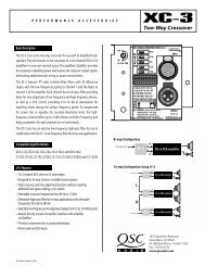
Connections<br />
AC Power Cord<br />
Insert the molded receptacle of the AC power cord into the AC power inlet on the back<br />
of the <strong>BASIS</strong> <strong>922uz</strong>. Plug the AC line connector into the AC outlet. The power supply<br />
will accept from 100 to 240 Volts AC, 47 to 440 Hertz, without any changes. If a different<br />
type of IEC power cord is required than supplied with your <strong>922uz</strong>, contact <strong>QSC</strong>’s<br />
Technical Services Department.<br />
CobraNet<br />
Connect one end of a category-5 cable terminated with a RJ45 plug into the CobraNet<br />
receptacle. Insert the RJ45 plug into the receptacle with the lock-tab oriented toward<br />
the bottom of the <strong>BASIS</strong> <strong>922uz</strong> and push firmly until the connector locks into place (usually<br />
an audible “click” can be heard). Connect the other end to the appropriate Cobra-<br />
Net network port.<br />
CobraNet and<br />
<strong>QSC</strong>ontrol connection.<br />
Accepts<br />
ruggedized or<br />
normal shell-less<br />
RJ45 plugs.<br />
Analog audio inputbalanced<br />
connection.<br />
<strong>QSC</strong>ontrol<br />
Connect one end of a category-5 cable terminated with an RJ45 plug into the <strong>QSC</strong>ontrol<br />
receptacle. Insert the RJ45 plug into the receptacle with the lock-tab oriented<br />
toward the bottom of the <strong>BASIS</strong> <strong>922uz</strong> and push firmly until the connector locks into<br />
place (usually an audible “click” can be heard). Connect the other end to the appropriate<br />
<strong>QSC</strong>ontrol.net network port.<br />
Analog Universal <strong>Audio</strong> Inputs<br />
Eight balanced audio inputs are provided, CH 1 INPUT - CH 8 INPUT. They accept<br />
everything from mic level to line level signals and are equipped with software-selectable<br />
+48V phantom power. Plug the input signal terminal block connectors into the<br />
input receptacles. Connection pin-out is printed on the rear label for reference. Refer to<br />
the illustrations for balanced and unbalanced connections. Use balanced audio inputs<br />
whenever possible.<br />
Each input has software-selectable +48V phantom power. Use caution<br />
when connecting equipment (particulary unbalanced equipment).<br />
Omni In<br />
The six Omni In connectors are two-pin terminal block connectors. They accept contact<br />
closure, TTL logic signals, 0-5 VDC control voltages, or 10k ohm variable resistors. The<br />
contact closure and logic devices accommodate on/off or state-change events; the variable<br />
resistor input provides full 8-bit resolution allowing for incremental-change<br />
events. Refer to the illustrations for connection recommendations. NOTE! +48 volts is<br />
the absolute maximum that can be applied to the + pin without damage. Voltage is with<br />
respect to chassis or the - pin.<br />
Logic Out<br />
The four Logic Out connectors are two-pin terminal block connectors. They provide<br />
CMOS logic level compatible signals for external devices.<br />
Relay Out<br />
Two sets of relay contacts are provided, RELAY OUT 1 and RELAY OUT 2. Contacts<br />
are floating and rated for 30VDC, 1A. There is one common terminal, one normallyclosed<br />
contact terminal and one normally-open contact terminal. These are labeled as<br />
C, NC and NO on the rear panel. When the relay is not energized, the C terminal is connected<br />
to the NC terminal and the NO terminal is not connected; when the relay is energized<br />
the C to NC connection is opened and the C to NO connection is closed.<br />
Analog audio inputunbalanced<br />
connection.<br />
Note jumper<br />
wire between - and<br />
ground.<br />
Omni In connections.<br />
Variable<br />
input must be 10k<br />
ohm variable<br />
resistor. Contact<br />
closure input can<br />
be a switch or<br />
relay contacts.<br />
These inputs can<br />
operate software<br />
“devices”. Negative<br />
(-) terminal is<br />
at chassis potential.<br />
Logic Out connections.<br />
Negative (-) terminal is<br />
at chassis potential.<br />
Positive (+) terminal<br />
logic level is switched<br />
using software.<br />
Relay Out connections.<br />
Refer to text,<br />
at left, for explanation.<br />
14