Create successful ePaper yourself
Turn your PDF publications into a flip-book with our unique Google optimized e-Paper software.
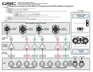
Monitor Chain<br />
The MONITOR CHAIN connector is a 5-pin terminal block connector. Input and output connections<br />
are balanced. The center pin is the shield connection for both the input and output<br />
of the monitor chain. Connection is shown at right. The left-most + and - terminals are for<br />
monitor chain input signals, while the right-most terminals are for monitor chain output signals.<br />
When powered down, a relay connects the input to the output, thus bypassing the<br />
<strong>BASIS</strong> <strong>922uz</strong> in the monitor chain.<br />
RS-232<br />
The RS-232 is an optional utility serial port for accessing advanced features. Connect to an<br />
available COM port on your PC and communicate using a terminal control program such as<br />
Windows Hyperterminal.<br />
Monitor Chain connection.<br />
See explanation, at left.<br />
In<br />
Out<br />
Use a normal serial data cable with a DB-9 male plug to connect to the <strong>BASIS</strong> <strong>922uz</strong>. To connect<br />
the cable, orient the connector properly, then push into the receptacle until it is firmly<br />
seated; tighten the retaining screws “finger tight”. Communications should be 9600 baud,<br />
no parity, 8 data bits, 1 stop bit, and flow control Xon/Xoff.<br />
Ports<br />
PORT A through PORT D are <strong>QSC</strong> DataPorts. When using the <strong>BASIS</strong> <strong>922uz</strong> with <strong>QSC</strong><br />
DataPort-equipped amplifiers or <strong>QSC</strong> DSP products (DSP-3, DSP-4) connect to the <strong>BASIS</strong><br />
<strong>922uz</strong> using <strong>QSC</strong> DataPort cables. The <strong>922uz</strong> supports up to eight channels of DataPort<br />
audio and amplifier status monitoring. This can be four 2-channel amplifiers or one 8-channel<br />
amplifier or other suitable combinations.<br />
To connect the cable, orient the connector properly, then push into the receptacle until it is<br />
firmly seated; tighten the retaining screws “finger tight”.<br />
LED Indicators<br />
When the <strong>BASIS</strong> <strong>922uz</strong> is plugged into a properly functioning AC outlet, it will power up and<br />
briefly display a welcome screen on the LCD display.<br />
POWER Indicator- This blue indicator illuminates when the <strong>BASIS</strong> <strong>922uz</strong> is plugged into a<br />
properly functioning AC source. There is no power switch on the <strong>BASIS</strong> <strong>922uz</strong>. This helps to<br />
prevent accidental system shutdowns.<br />
DIAGNOSTIC Indicator- This red diagnostic LED reports several possible operational conditions.<br />
During boot-up, it is used to continually blink a “dot-dash” pattern if the power-on<br />
memory self-test fails. During normal operation, if any non-recoverable system fault occurs,<br />
the diagnostic indicator will remain on, requiring a power restart. If this condition persists,<br />
contact <strong>QSC</strong>’s Technical Services for assistance.<br />
The diagnostic LED is also used to indicate an update is in progress during a remote firmware<br />
update cycle. First, the LED will blink slowly, indicating the memory erase cycle, then it<br />
will blink rapidly, indicating the memory write cycle. NOTE! During a firmware update, it<br />
is critical the unit remain powered on for the entire process in order to complete<br />
successfully.<br />
The diagnostic LED may also be controlled by using the <strong>QSC</strong>ontrol.net software. This feature<br />
is particularly helpful for identifying a particular unit.<br />
(continued, next page)<br />
15