CP370C SCR Selec Guide.qxd - Corken
CP370C SCR Selec Guide.qxd - Corken
CP370C SCR Selec Guide.qxd - Corken

You also want an ePaper? Increase the reach of your titles
YUMPU automatically turns print PDFs into web optimized ePapers that Google loves.
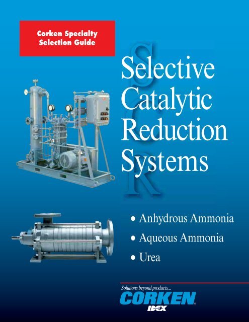
<strong>Corken</strong> Specialty<br />
<strong>Selec</strong>tion <strong>Guide</strong><br />
<strong>Selec</strong>tive<br />
Catalytic<br />
Reduction<br />
Systems<br />
• Anhydrous Ammonia<br />
• Aqueous Ammonia<br />
• Urea
<strong>Corken</strong>, a tradition of excellence<br />
As a unit of IDEX Corporation, <strong>Corken</strong> Inc. is a leader in<br />
specialized niche markets. To maintain our leadership in your<br />
industry requires continual Innovation, Diversity and Excellence.<br />
With over 50 years of global experience in liquefied gas handling,<br />
<strong>Corken</strong> offers unparalleled experience in rapidly changing ammonia<br />
handling systems. <strong>Corken</strong>’s exceptional reputation is built upon<br />
decades of maintaining the highest quality and customer service<br />
standards. <strong>Corken</strong> follows all of the guidelines set out by national<br />
agencies like the American National Standard Institute (ANSI) and<br />
the American Society of Mechanical Engineers (ASME) as they<br />
apply to our products.<br />
Through intimate contact within your industry, <strong>Corken</strong> is<br />
committed to applying new product technology and streamlining<br />
product selection.<br />
This specialized information packet is designed as a<br />
comprehensive guide to applying <strong>Corken</strong> products in your<br />
industry. It covers the capabilities, applications and guidelines for<br />
use of our compressors and pumps specifically for NH 3 transfer in<br />
selective catalyst reduction (<strong>SCR</strong>) systems.
<strong>SCR</strong> Definition and Overview<br />
<strong>Selec</strong>tive Catalytic Reduction (<strong>SCR</strong>): a post-combustion NO X reduction technology in which ammonia (NH 3 ) is<br />
added to the flue gas, which then passes through layers of a catalyst. The ammonia and NO X react on the surface of<br />
the catalyst, forming harmless nitrogen (N 2 ) and water vapor.<br />
New Environmental Protection Agency (EPA) regulations generate high demand for <strong>SCR</strong> systems to reduce NO X<br />
emissions from many large fossil-fuel fired industrial boilers and electricity generating units. The emerging demand<br />
for <strong>SCR</strong> systems also creates market opportunities for <strong>Corken</strong> equipment. <strong>SCR</strong> systems can reduce NO X levels by<br />
90% or more. The <strong>SCR</strong> market is mainly driven by environmental regulations and environmental technologies.<br />
<strong>SCR</strong> is well accepted by the industry as the best available technology, achieving the highest NO X reduction<br />
level. Technologies are changing rapidly in the NO X reduction <strong>SCR</strong> market and new alternative technologies<br />
keep coming to the market. Ammonia is currently considered the most effective NO X reducing agent used with<br />
<strong>SCR</strong> systems. Ammonia-based <strong>SCR</strong> systems can use three different NO X reducing agents: anhydrous ammonia,<br />
aqueous ammonia, and urea.<br />
ANHYDROUS AMMONIA TECHNOLOGY<br />
• Anhydrous ammonia is the most effective NO X reducing agent used in <strong>SCR</strong> systems. However, due to its<br />
hazardous nature, this form of ammonia can incur high compliance costs and safety concerns related to<br />
transportation, storing, and handling.<br />
• This technology has been in use in Europe since the 1980’s.<br />
• <strong>Corken</strong> pumps and compressors are used in anhydrous ammonia <strong>SCR</strong> systems.<br />
AQUEOUS AMMONIA TECHNOLOGY<br />
• Aqueous ammonia is commonly used in concentrations of 19% and 29% in <strong>SCR</strong> systems. When diluted to 19%<br />
concentration, aqueous ammonia is not classified as a toxic chemical.<br />
• Aqueous ammonia is generally considered safer than anhydrous ammonia because of its lower toxicity and lower<br />
storage pressure.<br />
• <strong>Corken</strong> pumps are used as feed pumps in aqueous ammonia systems.<br />
UREA BASED AMMONIA GENERATION TECHNOLOGY<br />
• Non-toxic urea is transported as a granular solid. It is mixed with water on site and converted to ammonia to be<br />
used as a NO X reducing agent in <strong>SCR</strong> systems.<br />
• This technology has recently gained a lot of interest from end-users due to minimal safety concerns. This<br />
technology is in the growth stage of its product life cycle.<br />
• <strong>Corken</strong> pumps are used in urea based <strong>SCR</strong> systems.
Where is <strong>Corken</strong> Equipment Applied in<br />
<strong>SCR</strong> Systems?<br />
NH 3 Railcar<br />
<strong>Corken</strong> unloading<br />
compressor for<br />
anhydrous ammonia<br />
NH 3 Storage<br />
Economizer<br />
Bypass<br />
Boiler<br />
Ammonia<br />
Injection<br />
<strong>Corken</strong> feed pump for<br />
anhydrous ammonia,<br />
aqueous ammonia,<br />
urea solution<br />
Coal<br />
Air<br />
<strong>SCR</strong><br />
Reactor<br />
Air<br />
Preaheater<br />
Electrostatic<br />
Precipitator<br />
Ash<br />
Stack<br />
Coal-fired power plant<br />
using <strong>SCR</strong> system<br />
Ash<br />
To Disposal
<strong>Corken</strong> Industrial Pumps and<br />
Compressors Meet the Challenges of<br />
<strong>SCR</strong> Ammonia Transfer<br />
COMPRESSORS FOR ANHYDROUS AMMONIA<br />
Proven Reliability<br />
<strong>Corken</strong> Industrial Compressors have been the standard in bulk ammonia transfer for 50 years. Our product and<br />
system experience in ammonia handling allows us to streamline your selection process.<br />
Sealing / Environmental Control<br />
<strong>Corken</strong>’s proven double distance piece (t-style) offering is specifically designed for hazardous gases. Optional<br />
ANSI/DIN flanges provide increased environmental security.<br />
One Stop Shopping<br />
<strong>Corken</strong> compressor packages are engineered to customer specifications. No other company offers the range<br />
of <strong>Selec</strong>tive Catalytic Reduction (<strong>SCR</strong>) ammonia pump and compressor system capability.<br />
PUMPS FOR ANHYDROUS AMMONIA, AQUEOUS AMMONIA<br />
AND UREA<br />
Wide Ranging Flows and Pressures<br />
<strong>Corken</strong> offers specialized pumping technologies where flows range from 1-400 gpm with differential pressures<br />
to 1,100 feet.<br />
Low Net Positive Suction Head (NPSH)<br />
No need to compromise system design or experience down time associated with vapor lock and cavitation.<br />
<strong>Corken</strong>’s unique design exceeds expectations where NPSH is as low as 1 ft.<br />
Continuous Duty Service<br />
<strong>Corken</strong> offers a continuous rated design. Reduced operating speed and free-floating impellers (no metal-tometal<br />
contact) provide years of trouble free service.<br />
Sealing Integrity<br />
Whether your application calls for mechanical sealing or sealless designs, <strong>Corken</strong> provides the widest range of options.<br />
Commitment and Support<br />
<strong>Corken</strong> products are backed by the strongest service commitment in your industry. We are pleased to provide<br />
you with our growing list of satisfied customers.
A Comprehensive <strong>Guide</strong> to <strong>SCR</strong> Systems<br />
WHY USE A COMPRESSOR TO TRANSFER HIGHLY VOLATILE LIQUIDS? . . . . . . . . . . . . . . . . . . 8<br />
GUIDE TO COMPRESSOR SELECTION . . . . . . . . . . . . . . . . . . . . . . . . . . . . . . . . . . . . . . . . . . . . . . . . 9<br />
Specifications. . . . . . . . . . . . . . . . . . . . . . . . . . . . . . . . . . . . . . . . . . . . . . . . . . . . . . . . . . . . . . . . . . . . . . . . . . . . . . . . . . . . . . . . 11<br />
Choose From a Variety of Mounting Arrangements to Suit Your Particular Application . . . . . . . . . . . . . . . . . . . . . . . . . . . . . . . . 11<br />
Outline Dimensions . . . . . . . . . . . . . . . . . . . . . . . . . . . . . . . . . . . . . . . . . . . . . . . . . . . . . . . . . . . . . . . . . . . . . . . . . . . . . . . . . . . 12<br />
Material Specifications. . . . . . . . . . . . . . . . . . . . . . . . . . . . . . . . . . . . . . . . . . . . . . . . . . . . . . . . . . . . . . . . . . . . . . . . . . . . . . . . . 15<br />
The Transfer Compressor Operating Principle . . . . . . . . . . . . . . . . . . . . . . . . . . . . . . . . . . . . . . . . . . . . . . . . . . . . . . . . . . . . . . . 16<br />
Economics of Using a Compressor. . . . . . . . . . . . . . . . . . . . . . . . . . . . . . . . . . . . . . . . . . . . . . . . . . . . . . . . . . . . . . . . . . . . . . . . 17<br />
Simplified Bulk Plant Piping Details . . . . . . . . . . . . . . . . . . . . . . . . . . . . . . . . . . . . . . . . . . . . . . . . . . . . . . . . . . . . . . . . . . . . . . 18<br />
Typical Transport Mounting Arrangement . . . . . . . . . . . . . . . . . . . . . . . . . . . . . . . . . . . . . . . . . . . . . . . . . . . . . . . . . . . . . . . . . . 18<br />
Ammonia Compressor <strong>Selec</strong>tion Table . . . . . . . . . . . . . . . . . . . . . . . . . . . . . . . . . . . . . . . . . . . . . . . . . . . . . . . . . . . . . . . . . . . . . 19<br />
Moving Liquid with Vapor . . . . . . . . . . . . . . . . . . . . . . . . . . . . . . . . . . . . . . . . . . . . . . . . . . . . . . . . . . . . . . . . . . . . . . . . . . . . . . 20<br />
Liquid Transfer and Vapor Recovery. . . . . . . . . . . . . . . . . . . . . . . . . . . . . . . . . . . . . . . . . . . . . . . . . . . . . . . . . . . . . . . . . . . . . . . 22<br />
Liquefied Gas Transfer Compressor Worksheets. . . . . . . . . . . . . . . . . . . . . . . . . . . . . . . . . . . . . . . . . . . . . . . . . . . . . . . . . . . . . . 23<br />
Compressor Foundation Design . . . . . . . . . . . . . . . . . . . . . . . . . . . . . . . . . . . . . . . . . . . . . . . . . . . . . . . . . . . . . . . . . . . . . . . . . . 25<br />
GUIDE TO PUMP SELECTION . . . . . . . . . . . . . . . . . . . . . . . . . . . . . . . . . . . . . . . . . . . . . . . . . . . . . . 28<br />
SC-Series Side Channel Pumps . . . . . . . . . . . . . . . . . . . . . . . . . . . . . . . . . . . . . . . . . . . . . . . . . . . . . . . . . . . . . . . . . . . . . . . . . . 29<br />
Principle of Side Channel Operation. . . . . . . . . . . . . . . . . . . . . . . . . . . . . . . . . . . . . . . . . . . . . . . . . . . . . . . . . . . . . . . . . . . . . . . 30<br />
<strong>Selec</strong>tion Overview Graphs . . . . . . . . . . . . . . . . . . . . . . . . . . . . . . . . . . . . . . . . . . . . . . . . . . . . . . . . . . . . . . . . . . . . . . . . . . . . . 31<br />
Instructions for <strong>Selec</strong>tion of Mechanical Seal Model . . . . . . . . . . . . . . . . . . . . . . . . . . . . . . . . . . . . . . . . . . . . . . . . . . . . . . . . . . 33<br />
Instructions for <strong>Selec</strong>tion of Magnetic Drive Model . . . . . . . . . . . . . . . . . . . . . . . . . . . . . . . . . . . . . . . . . . . . . . . . . . . . . . . . . . . 34<br />
Magnetic Coupling <strong>Selec</strong>tion Table . . . . . . . . . . . . . . . . . . . . . . . . . . . . . . . . . . . . . . . . . . . . . . . . . . . . . . . . . . . . . . . . . . . . . . . 35<br />
Performance Curves . . . . . . . . . . . . . . . . . . . . . . . . . . . . . . . . . . . . . . . . . . . . . . . . . . . . . . . . . . . . . . . . . . . . . . . . . . . . . . . . . . . 36<br />
Material Specifications. . . . . . . . . . . . . . . . . . . . . . . . . . . . . . . . . . . . . . . . . . . . . . . . . . . . . . . . . . . . . . . . . . . . . . . . . . . . . . . . . 48<br />
Model Number <strong>Selec</strong>tion <strong>Guide</strong> for Mechanical Seal Model . . . . . . . . . . . . . . . . . . . . . . . . . . . . . . . . . . . . . . . . . . . . . . . . . . . . 49<br />
Model Number <strong>Selec</strong>tion <strong>Guide</strong> for Magnetic Drive Model . . . . . . . . . . . . . . . . . . . . . . . . . . . . . . . . . . . . . . . . . . . . . . . . . . . . . 50<br />
Dimensional Drawings . . . . . . . . . . . . . . . . . . . . . . . . . . . . . . . . . . . . . . . . . . . . . . . . . . . . . . . . . . . . . . . . . . . . . . . . . . . . . . . . . 51<br />
Piping Recommendations . . . . . . . . . . . . . . . . . . . . . . . . . . . . . . . . . . . . . . . . . . . . . . . . . . . . . . . . . . . . . . . . . . . . . . . . . . . . . . . 53<br />
The <strong>Corken</strong> B166 Bypass Valve . . . . . . . . . . . . . . . . . . . . . . . . . . . . . . . . . . . . . . . . . . . . . . . . . . . . . . . . . . . . . . . . . . . . . . . . . . 60<br />
The <strong>Corken</strong> T166 Bypass Valve . . . . . . . . . . . . . . . . . . . . . . . . . . . . . . . . . . . . . . . . . . . . . . . . . . . . . . . . . . . . . . . . . . . . . . . . . . 61<br />
WARRANTY INFORMATION . . . . . . . . . . . . . . . . . . . . . . . . . . . . . . . . . . . . . . . . . . . . . . . . . . . . . . . 62<br />
CONVERSION FACTORS. . . . . . . . . . . . . . . . . . . . . . . . . . . . . . . . . . . . . . . . . . . . . . . . . . . . . . . . . . . 63<br />
PRODUCT APPLICATION FORM . . . . . . . . . . . . . . . . . . . . . . . . . . . . . . . . . . . . . . . . . . . . . . . . . . . . 64<br />
All Contents Copyright © 2000 <strong>Corken</strong>, Inc., a Unit of IDEX Corporation.<br />
3805 N.W. 36th St., Oklahoma City, OK 73112
Why Use a Compressor to Transfer Highly Volatile Liquids?<br />
Liquefied gases must be transferred from one container to another<br />
either with a liquid pump or a gas compressor, and there are very<br />
definite benefits from selecting either one. Because <strong>Corken</strong> has had<br />
many years of experience in manufacturing both pumps and<br />
compressors for volatile liquid service, it is possible for our<br />
personnel to analyze this problem objectively and present the<br />
following comparisons to assist you in making the proper choice.<br />
LIQUID PUMPS<br />
A liquid pump, such as the <strong>Corken</strong> Coro-Vane ® has the advantage of<br />
producing higher differential pressures than the compressor to<br />
overcome high pressure losses caused by inadequate discharge piping,<br />
pumping into small, hard to fill tanks, and particularly through meters.<br />
A compressor cannot successfully discharge volatile liquid through a<br />
meter. However, the liquid pump does have certain limitations:<br />
• Volatile liquids with their tendency to boil or "flash" readily<br />
whenever the pressure is reduced require particular attention to<br />
pump installation.<br />
• To reduce this "flashing" effect, pump inlet piping-must be<br />
designed carefully with larger and more expensive valves,<br />
strainers and flexible piping arrangements to provide the pump's<br />
required NPSH (net positive suction head).<br />
• Most tank cars have top outlets, necessitating a "siphon leg" which<br />
contributes to liquid flashing.<br />
• The flashing liquid may cause pump "vapor lock", with the<br />
attendant loss of capacity and accelerated wear on the shaft seals<br />
and running parts.<br />
• Tanks are seldom emptied entirely of liquid; uneven unloading sites<br />
and variations in the vehicle undercarriage increase this possibility.<br />
None of the valuable residual vapors remaining in the unloaded tank<br />
may be recovered.<br />
GAS COMPRESSORS<br />
A gas compressor will overcome many of the obstacles associated<br />
with transferring liquid with a pump, such as poor piping conditions<br />
and top outlet tanks. The compressor will do everything the pump<br />
will do in low pressure liquid transfer, with the same horsepower<br />
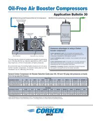
requirement, and will recover the valuable residual vapors. The<br />
quantities of recoverable residual vapors are shown in Figure 1, page<br />
16 for typical gases.<br />
Transports have bottom openings and may be unloaded with a liquid<br />
pump successfully. The amount of valuable vapors remaining usually<br />
is not as great as in a tank car, and a transporter understandably is<br />
reluctant to leave his expensive equipment for an hour or so while<br />
the residual vapors are being recovered. Because of these factors,<br />
many "transport only" bulk plants utilize only liquid pumps. Yet it is<br />
reasonable to expect that the plant operator could recover vapors for<br />
the period of time the driver is performing his accounting chores, if<br />
a plant compressor were available. Figure 1, page 17, illustrates that<br />
a large percentage of the vapors may be recovered in the first 15 to<br />
30 minutes. Actually, more equivalent pounds or gallons of vapor<br />
will be recovered during the first few minutes while the residual<br />
liquid is being vaporized than will be reclaimed during the same<br />
period of time later on. The vaporized liquid content is in addition to<br />
the values shown in Figure 1, page 17.<br />
Even when gas ownership does not change hands, as in the case when<br />
a producer delivers to his own terminal, the vapor recovery<br />
compressor can develop an increased transporting capacity of about<br />
3 percent! This means a fleet of 97 tank cars unloaded with vapor<br />
recovery can do the job of 100 when the vapor is not recovered!<br />
Maintenance of a pump or a compressor is about the same if the<br />
equipment is not abused. The liquid pump can be damaged seriously<br />
if allowed to run dry, either from "vapor locking" or after the<br />
unloading tank is emptied, whereas the compressor is remarkably<br />
resistant to this kind of abuse. You must, however, take action to<br />
prevent liquid entering the compressor.<br />
Safety of plant operation is a factor often not considered in<br />
compressor selection: a safety minded operator will use the versatile<br />
compressor to evacuate tanks and piping rather than "bleeding<br />
down". He will also find the purging of new tanks is more effectively<br />
done by first evacuating the air with the compressor.<br />
Today, in the gas distribution business with the price of product<br />
increasing and competition more pressing, profits are more difficult<br />
to produce than ever before. The profit contribution of vapor<br />
recovery may very well make the difference in an acceptable profit<br />
margin; the discussion on the "Economics of Compressor Operation"<br />
indicates this clearly, and is a logical method you may use to justify<br />
your own decision.<br />
Profits will continue to accrue whenever vapor recovery operations<br />
are performed.<br />
8
1<br />
<strong>Guide</strong> to Compressor <strong>Selec</strong>tion<br />
FEATURES<br />
ANSI FLANGED HEAD is made from ductile iron and is ideal for<br />
most industrial applications. ANSI flanges eliminate the possibility<br />
of leaks from threaded connections.<br />
PISTON ROD SEALS of glass-filled, self-lubricating Teflon ® are<br />
spring loaded and adjustable to compensate for lateral rod<br />
movement, wear and temperature variations. The seals stop gas<br />
leakage into the crankcase and crankcase oil entry into the<br />
compression cylinders.<br />
CROSSHEAD – PISTON ROD assemblies transmit the crankshaft<br />
motion into vertical, reciprocating piston motion. The vertical piston<br />
motion provides no side thrust, and thus the pistons require no rider<br />
rings. The crosshead and the hardened steel piston rod are assembled<br />
and machined as one piece to assure perfect alignment between the<br />
connecting rod wrist pin and the piston rod.<br />
CRANKSHAFTS have integral, balanced counterweights for smoother<br />
operation. Bearing surfaces are extra large and the crankshaft is<br />
precision ground to size. The crankshafts are rifle drilled for positive<br />
oil distribution to the connecting rods and wrist pin bearings.<br />
Teflon ® piston rings, honed cylinder walls and low lift valves make<br />
this unique pumping system possible. The pistons are arranged not<br />
to contact the cylinder wall and are designed to be removable from<br />
the cylinder and piston rod without disturbing the cylinder.<br />
INTERNAL PROTECTION DEVICES guard against liquid slugging.<br />
Volatile liquid transfer incurs risk of liquid entering or "slugging" the<br />
compressor. Reliable relieving devices are built into the cylinder head<br />
and suction valves to prevent damage from reasonable amounts of<br />
liquid. An optional liquid trap provides additional protection<br />
externally, and is recommended for all plant installations.<br />
LARGE FLYWHEEL FAN provides maximum crankcase cooling<br />
and smooth operation.<br />
DUCTILE IRON CONNECTING RODS provide great strength for<br />
heavy duty applications. The connecting rod bearing inserts are<br />
steel backed, babbit-lined, removable automotive type. The rod is<br />
constructed with a communicating lubrication port from the crank<br />
to the honed bronze wrist pin bearing for lubrication from the<br />
crankcase oil pump.<br />
Teflon ® is a registered trademark of DuPont.<br />
THE CRANKCASE is operated at atmospheric pressure, but is<br />
totally enclosed with an automatic breather valve to prevent entrance<br />
of dust or foreign matter. Since no oil is consumed in the<br />
compression process, the oil remains clean in the crankcase, and the<br />
major sources of crankcase wear are virtually eliminated. The oil<br />
stays in the crankcase where it belongs! The crankshaft running<br />
parts are pressure lubricated by filtered oil from an automatically<br />
reversible pump (reversing does not require disassembly). An easyto-read,<br />
dial-type, oil pressure gauge indicates proper functioning of<br />
the lubrication system.<br />
TAPERED ROLLER BEARINGS are mounted on each end of the<br />
crankshaft to absorb radial and thrust loads. These oversize bearings<br />
assure added years of service, and can be adjusted easily from the<br />
external position of the crankcase if required.<br />
CUSHIONED VALVES are designed and lapped for long life. The<br />
valve bumpers have a gas cushion to prevent valve slamming and<br />
provide quiet operation. Each valve is easily removable for inspection.<br />
OIL-FREE CYLINDER AND PISTON DESIGN permits these<br />
compressors to operate with no lubrication of any kind in the<br />
compression cylinders. A combination of self-lubricating, filled<br />
FD491 COMPRESSOR<br />
10
<strong>Guide</strong> to Compressor <strong>Selec</strong>tion 1<br />
SPECIFICATIONS<br />
MECHANICAL SPECIFICATIONS<br />
MODEL SIZE<br />
SPECIFICATION FD291 FD491 FD691<br />
Number of Stages 1 1 1<br />
Number of Cylinders 2 2 2<br />
Bore of Cylinder, inches (cm) 3 (7.62) 4 (10.16) 4.5 (11.43)<br />
Stroke, inches (cm) 2.5 (6.35) 3 (7.62) 4 (10.16)<br />
Piston Displacement, cfm (m 2 /hr)<br />
Minimum at 400 rpm 8 (18.6) 17 (28.9) 29 (49.3)<br />
Maximum at 825 rpm 16 (27.2) 36 (61.2) 60 (102)<br />
Maximum Discharge Pressure, psig (bars g) 335 (23.1) 335 (23.1) 335 (23.1)<br />
Maximum Compression Ratio: Continuous Duty 5 5 5<br />
Intermittent Duty 7 7 7<br />
Maximum Allowable Driver Size, hp 15 20 30<br />
COMPRESSOR SELECTION CHART<br />
MOTOR APPROXIMATE CAPACITY<br />
COMPRESSOR SIZE, FOR AMMONIA<br />
MODEL HORSEPOWER 1 GPM (LIT/MIN) 2<br />
3 44 (166)<br />
291 5 77 (291)<br />
7-1/2 88 (333)<br />
5 77 (291)<br />
491 7-1/2 110 (416)<br />
10 148 (560)<br />
15 198 (749)<br />
10 132 (500)<br />
691 15 198 (749)<br />
20 265 (1,003)<br />
25 330 (1,249)<br />
NOTES:<br />
1. The driver horsepower shown is based upon recovering residual vapors in moderate climates.<br />
2. The actual capacity will vary depending upon piping factors. The capacities shown are conservative and may be increased as<br />
much as 10% in well designed plants.<br />
CHOOSE FROM A VARIETY OF MOUNTING ARRANGEMENTS TO SUIT YOUR PARTICULAR APPLICATION<br />
There are a number of standard base mounted gas compressor units to<br />
fit most installations, but special mounting and piping arrangements<br />
can be designed and manufactured to fit your particular needs.<br />
BARE<br />
Gas compressor with flywheel.<br />
STYLE – 103<br />
Gas compressor unit with pressure gauges, steel baseplate,<br />
adjustable driver slide base, v-belt drive and enclosed belt guard –<br />
ready to receive an electric motor driver.<br />
STYLE – 107F<br />
Complete gas compressor bulk plant unit with ANSI flanged<br />
mounting includes pressure gauges / block valves, ASME code<br />
stamped ANSI flange inlet trap with one or two liquid level<br />
switches, flanged trap relief valve, manual tank drain, non-lube<br />
ANSI flanged four-way valve and flange welded interconnecting<br />
piping. Mounted on a steel base, v-belt drive and enclosed belt<br />
guard. Motor and flanged compressor not included.<br />
Style – 109F<br />
Gas compressor unit with ANSI flanged mounting includes pressure<br />
gauges / block valves, ASME code stamped ANSI flange inlet trap<br />
with two liquid level switches, flanged trap relief valve and manual<br />
tank drain and flange welded interconnecting piping. Mounted on a<br />
steel base, v-belt drive and enclosed belt guard. Motor and flanged<br />
compressor not included.<br />
11
0 10 20 30 40<br />
0 1 2<br />
3<br />
4 1/2<br />
(11.43)<br />
MERCER RELIEF VALVE<br />
1" 300# X 2" 150# ANSI<br />
FLANGE PIPE-AWAY<br />
SET AT 350 PSIG<br />
LIQUID TRAP<br />
INLET<br />
PRESSURE<br />
GAUGE<br />
FOUR WAY<br />
CONTROL VALVE<br />
3/4" 300 LB<br />
R.F. FLANGE<br />
UNLOADERS<br />
(OPTIONAL)<br />
SUCTION VALVE<br />
DISCHARGE<br />
PRESSURE<br />
GAUGE<br />
1" 300 LB. R.F. FLANGE<br />
RELIEF VALVE TO BE<br />
CUSTOMER SUPPLIED<br />
HIGH TEMPERATURE<br />
SHUTDOWN SWITCH<br />
(OPTIONAL)<br />
<strong>Guide</strong> to Compressor <strong>Selec</strong>tion<br />
OUTLINE DIMENSIONS – FD291-107F<br />
5-1/4<br />
(13.34)<br />
BELTGUARD<br />
14-1/8 (35.88)<br />
18-1/2 (46.99)<br />
20 (50.80)<br />
10-1/8<br />
(25.64)<br />
HIGH LIQUID LEVEL<br />
SHUTDOWN SWITCH<br />
1-1/2" 300 LB R.F.<br />
ANSI FLANGE<br />
1/2" NPT<br />
CRANKCASE<br />
OIL DRAIN<br />
1-1/2 (3.81)<br />
2-13/16 (7.14)<br />
49-13/16<br />
(126.53)<br />
44-3/16<br />
(112.24)<br />
34-1/2<br />
(87.60)<br />
28-1/4<br />
(71.79)<br />
19-3/8<br />
(49.21)<br />
6-7/8<br />
(17.46)<br />
4<br />
(10.16)<br />
DRAIN VALVE<br />
1" 300 LB R.F.<br />
ANSI FLANGE<br />
1-1/4 (3.17)<br />
15-1/2 (39.45)<br />
21 (53.34)<br />
21-5/16 (54.13)<br />
CRANKCASE<br />
HEATER<br />
(OPTIONAL)<br />
47 (119.38)<br />
NEMA 7 LOW OIL<br />
PRESSURE SWITCH<br />
(OPTIONAL)<br />
66-3/4 (169.55)<br />
68 (172.72)<br />
ELECTRIC MOTOR<br />
DRIVER<br />
PIPE<br />
TAP<br />
ADJUSTABLE<br />
DRIVER<br />
SLIDE BASE<br />
USE EIGHT<br />
1/2" ANCHOR<br />
BOLTS<br />
ALL DIMENSIONS IN INCHES(CM)<br />
1<br />
12
PSI<br />
KG/CM‹<br />
1302<br />
0 10 20 30 40<br />
1 2<br />
0 3<br />
LIQUID TRAP<br />
INLET<br />
PRESSURE GAUGE<br />
4-1/2<br />
(114.3)<br />
MERCER RELIEF VALVE<br />
1" 300# x 2" 150# ANSI<br />
FLANGE PIPE-AWAY<br />
SET AT 350 PSIG<br />
SUCTION VALVE<br />
UNLOADERS (OPTIONAL)<br />
FOUR WAY<br />
CONTROL VALVE<br />
1-1/4" 300 LB<br />
R.F. FLANGE<br />
DISCHARGE<br />
PRESSURE GAUGE<br />
1" 300 LB R.F. FLANGE<br />
RELIEF VALVE TO BE<br />
CUSTOMER SUPPLIED<br />
HIGH TEMPERATURE<br />
SHUTDOWN SWITCH<br />
(OPTIONAL)<br />
5-1/4<br />
(13.34)<br />
13<br />
BELTGUARD<br />
12-7/8 (32.66)<br />
18-1/2 (46.99)<br />
20 (50.80)<br />
11-3/4<br />
(29.80)<br />
HIGH LIQUID<br />
LEVEL SHUTDOWN<br />
SWITCH 1-1/2"<br />
300 LB R.F.<br />
ANSI FLANGE<br />
1/2" NPT<br />
CRANK CASE<br />
OIL DRAIN<br />
1-1/2 (3.81)<br />
1-9/16 (3.97)<br />
53-1/4<br />
(135.27)<br />
47-5/8<br />
(120.98)<br />
38-3/8<br />
(97.41)<br />
31-5/16<br />
(79.46)<br />
22-13/16<br />
(57.96)<br />
10-5/16<br />
(26.21)<br />
4<br />
(10.16)<br />
DRAIN VALVE<br />
1" 300 LB R.F.<br />
ANSI FLANGE<br />
1-1/4 (3.17)<br />
13-13/16 (35.16)<br />
18-5/16 (46.51)<br />
21 (53.34)<br />
CRANKCASE<br />
HEATER<br />
(OPTIONAL)<br />
47 (119.38)<br />
NEMA 7 LOW OIL<br />
PRESSURE SWITCH<br />
(OPTIONAL)<br />
66-3/4 (169.55)<br />
68 (172.72)<br />
ELECTRIC MOTOR<br />
DRIVER<br />
PIPE<br />
TAP<br />
ADJUSTABLE<br />
DRIVER<br />
SLIDE BASE<br />
USE EIGHT<br />
1/2" ANCHOR<br />
BOLTS<br />
ALL DIMENSIONS IN INCHES(CM)<br />
OUTLINE DIMENSIONS – FD491-107F<br />
<strong>Guide</strong> to Compressor <strong>Selec</strong>tion 1
0 10 20 30 40<br />
1 2<br />
0 3<br />
4-1/2 (11.43)<br />
MERCER RELIEF VALVE<br />
1" 300# x 2" 150# ANSI<br />
FLANGE PIPE-AWAY<br />
SET AT 350 PSIG<br />
<strong>Guide</strong> to Compressor <strong>Selec</strong>tion<br />
THREE-WAY SOLENOID<br />
UNLOADER VALVE<br />
(OPTIONAL)<br />
LIQUID TRAP<br />
BELTGUARD<br />
5-1/2<br />
(13.97)<br />
3/4 (1.91)<br />
14-1/4 (36.20)<br />
23-1/4 (59.06)<br />
24 (60.96)<br />
15-3/16<br />
(38.50)<br />
HIGH LIQUID LEVEL<br />
SHUTDOWN SWITCH<br />
1-1/2" 300 LB R.F.<br />
ANSI FLANGE<br />
HIGH LIQUID LEVEL<br />
ALARM SWITCH<br />
1-1/2" 300 LB R.F.<br />
ANSI FLANGE<br />
1/2" NPT<br />
CRANKCASE DRAIN<br />
1/8 (0.40)<br />
85-1/8<br />
(216.30)<br />
79-1/2<br />
(202.01)<br />
35<br />
(88.90)<br />
28-1/2<br />
(72.39)<br />
INLET<br />
PRESSURE<br />
GAUGE<br />
(OPTIONAL)<br />
10-1/2<br />
(26.67) 6<br />
(15.24)<br />
FOUR<br />
WAY<br />
CONTROL<br />
VALVE 2"<br />
300 LB<br />
R.F. FLANGE<br />
NEMA 7 LOW<br />
OIL PRESSURE<br />
SWITCH<br />
(OPTIONAL)<br />
DRAIN VALVE<br />
1-1/2" 300 LB R.F.<br />
ANSI FLANGE<br />
9 (22.86)<br />
9-3/8 (23.80)<br />
27 (68.58)<br />
39-1/4 (99.70)<br />
45 (114.30)<br />
SUCTION VALVE<br />
UNLOADERS<br />
(OPTIONAL)<br />
INLET<br />
PRESSURE<br />
GAUGE<br />
CRANKCASE<br />
HEATER<br />
(OPTIONAL)<br />
1-3/8 (3.48)<br />
63 (160.02)<br />
72 (182.88)<br />
DISCHARGE<br />
PRESSURE GAUGE<br />
1" 300 LB R.F.<br />
FLANGE RELIEF VALVE<br />
CUSTOMER SUPPLIED<br />
DISCHARGE<br />
TEMPERATURE<br />
GAUGE<br />
(OPTIONAL)<br />
ADJUSTABLE<br />
DRIVER<br />
SLIDE BASE<br />
HIGH TEMPERATURE<br />
SHUTDOWN SWITCH<br />
(OPTIONAL)<br />
DISCHARGE<br />
PRESSURE<br />
GAUGE<br />
(OPTIONAL)<br />
ELECTRIC<br />
MOTOR<br />
DRIVER<br />
PIPE<br />
TAP<br />
USE EIGHT<br />
3/4"<br />
ANCHOR<br />
BOLTS<br />
8-3/4<br />
(22.23)<br />
54-7/8<br />
(139.36)<br />
53-1/8<br />
(134.99)<br />
36-5/8<br />
(93.01)<br />
DIMENSIONS IN INCHES (CM)<br />
1<br />
14<br />
OUTLINE DIMENSIONS - FD691-107F
<strong>Guide</strong> to Compressor <strong>Selec</strong>tion 1<br />
MATERIAL SPECIFICATIONS<br />
STANDARD<br />
OPTIONAL<br />
PART SIZE MATERIAL SIZE MATERIAL<br />
HEAD, CYLINDER<br />
91, 191, 291,<br />
DUCTILE IRON<br />
DUCTILE IRON ASTM A536 492-692<br />
491, 691 DIN 1693 666-40.3<br />
DISTANCE PIECE,<br />
CROSSHEAD GUIDE<br />
CRANKCASE, FLYWHEEL<br />
ALL GRAY IRON ASTM A48, CLASS 30<br />
BEARING CARRIER<br />
FLANGE 691 DUCTILE IRON ASTM A536 690, 691, 690-4 STEEL WELDING<br />
291 17-4 PH STAINLESS STEEL<br />
VALVE SEAT AND BUMPER 391, 491, 491-3 DUCTILE IRON ASTM A536<br />
691 STAINLESS STEEL<br />
291 410 STAINLESS STEEL 291 PEEK<br />
VALVE PLATE 491, 491-3 17-7 PH STAINLESS STEEL<br />
691 STAINLESS STEEL 691 PEEK<br />
VALVE SPRING<br />
291, 691 17-7 STAINLESS STEEL<br />
491, 491-3 INCONEL<br />
VALVE GASKETS ALL SOFT ALUMINUM ALL COPPER, IRON-LEAD<br />
PISTON 291, 491, 691 GRAY IRON ASTM A48, CLASS 30<br />
PISTON ROD<br />
ALL<br />
C1050 STEEL, NITROTEC, ALL D & T STYLE<br />
ROCKWELL 60C<br />
MODELS<br />
CHROME OXIDE COATING<br />
CROSSHEAD ALL GRAY IRON ASTM A48, CLASS 30<br />
PISTON RINGS ALL PTFE, GLASS AND MOLY FILLED ALL SPECIAL ORDER<br />
OR ALLOY 50<br />
MATERIALS AVAILABLE<br />
PISTON RING EXPANDERS ALL 302 STAINLESS STEEL NONE<br />
HEAD GASKET 291, 491, 691 O-RING (BUNA-N) 291, 491, 691 PTFE, VITON ® , NEOPRENE ®<br />
ADAPTER PLATE,<br />
PACKING CARTRIDGE, ALL DUCTILE IRON ASTM A536<br />
CONNECTING ROD<br />
PACKING RINGS<br />
ALL<br />
PTFE, GLASS AND MOLY FILLED<br />
SPECIAL ORDER<br />
OR ALLOY 50<br />
MATERIALS AVAILABLE<br />
CRANKSHAFT ALL DUCTILE IRON ASTM A536<br />
CONNECTING ROD BEARING ALL BIMETAL D-2 BABBIT<br />
WRIST PIN ALL C1018 STEEL, ROCKWELL 62C<br />
WRIST PIN BUSHING ALL BRONZE SAE 660<br />
MAIN BEARING ALL TAPERED ROLLER<br />
INSPECTION PLATE ALL ALUMINUM<br />
O-RINGS ALL BUNA-N ALL PTFE, VITON ® , NEOPRENE ®<br />
RETAINER RINGS ALL STEEL<br />
MISCELLANEOUS GASKETS ALL COROPRENE<br />
VITON ® AND NEOPRENE ® ARE REGISTERED TRADEMARKS OF DUPONT.<br />
15
1<br />
<strong>Guide</strong> to Compressor <strong>Selec</strong>tion<br />
THE TRANSFER COMPRESSOR OPERATING PRINCIPLE<br />
Most people are somewhat familiar with the operating principles of<br />
a liquid pump; the transfer compressor is another matter entirely.<br />
Visualize a tank car full of volatile liquid on a plant siding ready to<br />
be unloaded into storage tanks. Both tank car and storage tank are<br />
normally under approximately the same vapor pressure.<br />
A piping connection is made between the tops of vapor sections of the<br />
tank car and the storage tank, and a similar connection is made between<br />
the liquid sections of the two tanks. As the connections are opened, the<br />
liquid will seek its own level and then flow will stop. However, by<br />
creating pressure in the tank car sufficient to overcome pipe friction and<br />
any static elevation difference between the tanks, all the liquid is forced<br />
into the storage tank quickly. The gas compressor does this job by<br />
drawing gas from the top of the storage tank. This procedure lowers the<br />
storage tank pressure slightly and increases the tank car pressure,<br />
normally 10 to 20 psig (0.7 to 1.4 bars), above vapor pressure.<br />
After all possible liquid has been transferred in this manner, some<br />
liquid still remains, and the tank car is still full of valuable vapors.<br />
To remove the remaining liquid and the residual vapors, piping<br />
connections are reversed by means of the compressor four-way<br />
control valve, and the direction of flow through the compressor is<br />
reversed. After closing the connection between the liquid sections of<br />
the two tanks, the gas can now be drawn from the top of the tank car<br />
thereby vaporizing the remaining liquid. After all liquid has been<br />
vaporized, the compressor continues to draw gas from the tank car<br />
until the tank car pressure is reduced to an economical point.<br />
The recovered vapors must be discharged into the storage tank liquid<br />
section where they will be condensed. If the recovered vapors are not<br />
condensed, the storage tank will develop an excessive pressure.<br />
Vapor Recovery Line<br />
16
Any claim of an equipment manufacturer should be supported by facts,<br />
including the economics or payout calculations. If the profitability of<br />
a piece of machinery cannot be proven, it probably should not be<br />
purchased. The "proof of profit" of an unloading compressor is quite<br />
simple, if certain conservative assumptions are agreed upon:<br />
1 . Either a liquid pump or a compressor must be used to transfer<br />
the liquid product.<br />
2. The liquid transfer capacity of either a pump or a compressor,<br />
horsepower for horsepower, is comparable. In the <strong>Corken</strong> line, a<br />
gas compressor requires the same horsepower for liquid transfer<br />
only as does a liquid pump.<br />
3. Since a transfer compressor may recover residual vapors, and a<br />
liquid pump cannot, it is to be expected that the horsepower<br />
requirements for this cycle of operation are greater for a compressor.<br />
4. Only the difference in cost between the compressor and its motor<br />
and that of a pump and its motor is to be considered in the payout<br />
since one or the other must be utilized to transfer the liquid.<br />
5. The cost of operation of the compressor for the vapor recovery<br />
cycle is offset by the recovery of the vaporized liquid left in the<br />
tank after the transfer of all possible liquid is completed.<br />
VAPOR LEFT IN A 33,000 WATER GALLON<br />
(124,905 LITER) CAPACITY TANK CAR<br />
EXPRESSED IN LIQUID CAPACITY<br />
TANK CAR PRESSURE GALLONS (LITERS) POUNDS (KILOGRAMS)<br />
PSIG (BARS) 1 OF LP GAS 2 OF AMMONIA 2<br />
200 (13.79) –– 2,090 (948)<br />
175 (12.06) 1,170 (4428) 1,790 (812)<br />
150 (10.34) 970 (3671) 1,490 (676)<br />
125 (8.61) 770 (2914) 1,190 (540)<br />
100 (6.90) 570 (2157) 890 (404)<br />
75 (5.17) 370 (1400) 590 (268)<br />
50 (3.45) 170 (643) 290 (132)<br />
NOTES:<br />
1. This pressure is that of the tank car before vapor recovery<br />
operations are begun. Capacities are based upon recovering<br />
vapors to 25 psig (1.72 bars).<br />
2. There are several different tank car and transport tank<br />
capacities. When the unloading tank is of different capacity<br />
than 33,000 gallons, the liquid recovery capacities shown<br />
here will be proportional. For example, if the tank car is only<br />
11,000 water gallon capacity, the values shown here will be<br />
multiplied by 11,000 ÷ 33,000, or one third.<br />
<strong>Guide</strong> to Compressor <strong>Selec</strong>tion 1<br />
FIGURE 1<br />
ECONOMICS OF USING A COMPRESSOR<br />
Example A:<br />
How many tank cars of propane, 33,000 wg capacity, must be unloaded<br />
of vapor to pay for a $4,940 compressor? For the sake of simplicity, we<br />
shall be unloading cars with an average pressure of 125 psig, and a<br />
product cost, including freight, of $0.52 per gallon. A liquid pump of<br />
comparable capacity costs approximately $1,525. The recoverable vapors<br />
in equivalent gallons of liquid are shown in Figure 1 as 770 gallons.<br />
Number of Tank Cars =<br />
$4,940-$1,525<br />
= 8<br />
770 gal. x $0.52/gal.<br />
Only eight tank cars to pay for a 15 hp compressor unit ... thereafter<br />
all vapors recovered are profit!!!<br />
Example B:<br />
How many tank cars of ammonia, 11000 wg capacity, must be<br />
unloaded of vapor to pay for a 90 gpm, 5 hp compressor, if the tank<br />
car pressures are approximately 150 psig, and the product value is<br />
$225 per ton, or $0.113 per pound? A 2-1/2” liquid pump of the same<br />
horsepower would remove the liquid as quickly as the compressor. The<br />
approximate difference in cost between the compressor and pump is<br />
$2,860. Figure 1 shows 1,490 equivalent lbs. of vapor remaining in a<br />
33,000 wg car; since our example tank car is only 11,000 wg, the<br />
remaining equivalent vapor is approximately 500 lbs.<br />
$2,860<br />
Number of Tank Cars =<br />
= 50<br />
500 lbs. x $0.113<br />
PROPANE EVACUATION TIME FOR 33,000<br />
WATER GALLON (124,905 LITER) CAPACITY<br />
TANK CAR<br />
10<br />
150<br />
9 125<br />
8<br />
7 100<br />
6<br />
5 75<br />
4<br />
3<br />
50<br />
2 25<br />
1<br />
0 0<br />
0 1 2 3 4 5<br />
TIME - HOURS<br />
NOTES:<br />
1. Economic recovery time is about three hours. More than half<br />
of economically recoverable vapor is removed in the first hour.<br />
2. Vapor recovery is economic to about 25 percent of<br />
storage tank pressure.<br />
3. Curve is based on the use of a 36 cfm (1,020 lit/min)<br />
displacement <strong>Corken</strong> dry-cylinder model 491<br />
compressor recovering vapor through 1-1/2" vapor<br />
piping into 150 psig (10.34 bars) storage tank pressure.<br />
TANK CAR PRESSURE<br />
BARS<br />
PSIG<br />
17
1<br />
<strong>Guide</strong> to Compressor <strong>Selec</strong>tion<br />
SIMPLIFIED BULK PLANT PIPING DETAILS<br />
Installation piping details are available for the arrangement shown here or for larger and more complex operations.<br />
Vapor line to vapor<br />
section of storage<br />
Vapor line to liquid phase<br />
for vapor recovery<br />
Relief valve<br />
Check valve<br />
A<br />
C<br />
Four-way<br />
valve<br />
Vapor line to loading<br />
and unloading risers<br />
B<br />
A<br />
B<br />
C<br />
Four-way<br />
valve<br />
Position<br />
One<br />
Position<br />
Two<br />
SERVICE<br />
VALVES<br />
TO PERFORM FOUR-WAY A B C<br />
1. Unload into Position Open Open Close<br />
Storage Tank One<br />
2. Recover Vapors Position Close Open Open<br />
into Storage Tank Two<br />
3. Load Out from Position Open Open Close<br />
Storage Tank Two<br />
FIGURE 2<br />
TYPICAL TRANSPORT MOUNTING ARRANGEMENT<br />
Many companies increase their operating efficiency by equipping their transports with <strong>Corken</strong> compressors, enabling them to handle a greater variety<br />
of liquids with complete independence from the pumping facilities at the destination. The increased time savings in unloading pays for the compressor.<br />
<strong>Corken</strong> compressors often are mounted behind the tractor cab for direct drive from the truck power take off (PTO) or through a V-belt arrangement.<br />
An engine driven compressor is used whenever it is impractical to use the truck engine, and it may be mounted anywhere on the cab or tanker.<br />
DIRECT DRIVE MOUNTING: The compressor is hung inside the<br />
main truck frame in line with the PTO. Power is transmitted through<br />
a U-joint drive shaft directly to the compressor. Use extended<br />
crankshaft compressor models.<br />
BELT DRIVE MOUNTING: The location of the fifth wheel and<br />
design of the tanks determine whether the compressor can be<br />
mounted behind the cab, above the frame, or outside the frame.<br />
18
<strong>Guide</strong> to Compressor <strong>Selec</strong>tion 1<br />
AMMONIA COMPRESSOR SELECTION TABLE<br />
DRIVER HORSEPOWER<br />
LIQUID<br />
LIQUID<br />
TRANSFER TRANSFER<br />
AND<br />
WITHOUT<br />
DRIVER SHEAVE RESIDUAL RESIDUAL<br />
SIZE P.D. (2) VAPOR VAPOR PIPING SIZE<br />
CAPACITY DISPLACEMENT COMPRESSOR 1750 1450 RECOVERY RECOVERY (3)<br />
SERVICE GPM (1) CFM MODEL RPM RPM RPM 100°F 80°F 100°F 80°F VAPOR LIQUID<br />
45 8 291 390 A 3.4 B 4.0 5 3 3 3 1 1-1/2<br />
50 9 291 435 A 3.8 B 4.6 5 5 3 3 1 1-1/2<br />
56 10 291 490 B 4.4 B 5.2 5 5 5 3 1 2<br />
UNLOADING 62 11 291 535 B 4.8 B 5.8 7-1/2 5 5 5 1 2<br />
SINGLE TANK 67 12 291 580 B 5.2 B 6.2 7-1/2 5 5 5 1 2<br />
CAR OR 72 13 291 625 B 5.6 B 6.6 7-1/2 5 5 5 1-1/4 2<br />
TRANSPORT 80 14 291 695 B 6.2 B 7.4 7-1/2 7-1/2 7-1/2 5 1-1/4 2<br />
85 15 291 735 B 6.6 B 8.0 10 7-1/2 7-1/2 7-1/2 1-1/4 2-1/2<br />
85 15 491 345 A 3.0 A 3.6 7-1/2 7-1/2 5 5 1-1/4 2-1/2<br />
90 16 291 780 B 7.0 B 8.6 10 7-1/2 7-1/2 7-1/2 1-1/4 2-1/2<br />
90 16 491 370 A 3.2 A 3.8 10 7-1/2 5 5 1-1/4 2-1/2<br />
96 17 491 390 A 3.4 B 4.0 10 7-1/2 5 5 1-1/4 3<br />
102 18 491 415 A 3.6 B 4.4 10 7-1/2 7-1/2 7-1/2 1-1/4 3<br />
107 19 491 435 A 3.8 B 4.6 10 7-1/2 7-1/2 7-1/2 1-1/4 3<br />
110 20 491 445 B 4.0 B 4.8 10 7-1/2 7-1/2 7-1/2 1-1/4 3<br />
115 21 491 470 B 4.2 B 5.0 10 7-1/2 7-1/2 7-1/2 1-1/4 3<br />
UNLOADING 120 22 491 490 B 4.4 B 5.2 15 10 7-1/2 7-1/2 1-1/4 3<br />
TWO OR 126 23 491 515 B 4.6 B 5.6 15 10 7-1/2 7-1/2 1-1/4 3<br />
MORE TANK 131 24 491 535 B 4.8 B 5.8 15 10 10 7-1/2 1-1/4 3<br />
CARS AT 138 25 491 560 B 5.0 B 6.0 15 10 10 7-1/2 1-1/4 3<br />
ONE TIME, 142 26 491 580 B 5.2 B 6.2 15 10 10 7-1/2 1-1/4 3<br />
OR LARGE 148 27 491 605 B 5.4 B 6.4 15 10 10 10 1-1/4 3<br />
TRANSPORT 153 28 491 625 B 5.6 B 6.6 15 10 10 10 1-1/2 3<br />
WITH EXCESS 160 29 491 650 B 5.8 B 7.0 15 15 10 10 1-1/2 3<br />
FLOW VALVES 165 30 491 670 B 6.0 15 15 15 10 1-1/2 3<br />
OF ADEQUATE 165 30 691 400 B 4.4 B 5.2 15 15 10 10 1-1/2 3<br />
CAPACITY 170 31 491 695 B 6.2 B 7.4 15 15 15 10 1-1/2 3<br />
173 31 691 420 B 4.6 B 5.6 15 15 10 10 1-1/2 3<br />
181 32 491 740 B 6.6 B 8.0 15 15 15 15 1-1/2 3<br />
180 32 691 440 B 4.8 B 5.8 15 15 10 10 1-1/2 3<br />
188 34 691 455 B 5.0 B 6.0 20 15 10 10 1-1/2 3<br />
195 35 691 475 B 5.2 B 6.2 20 15 10 10 1-1/2 3<br />
203 36 691 495 B 5.4 B 6.4 20 15 15 10 1-1/2 3<br />
211 38 691 510 B 5.6 B 6.8 20 15 15 10 1-1/2 4<br />
218 39 691 530 B 5.8 B 7.0 20 15 15 15 1-1/2 4<br />
226 41 691 550 B 6.0 A 7.0 20 15 15 15 1-1/2 4<br />
233 42 691 565 B 6.2 B 7.4 20 15 15 15 2 4<br />
UNLOADING 240 43 691 585 B 6.4 A 7.4 20 20 15 15 2 4<br />
LARGE 248 45 691 605 B 6.6 B 8.0 20 20 15 15 2 4<br />
TANK CAR, 255 45 691 620 B 6.8 25 20 15 15 2 4<br />
MULTIPLE 263 47 691 640 B 7.0 A 8.2 25 20 15 15 2 4<br />
VESSELS, 278 48 691 675 B 7.4 B 8.6 25 20 15 15 2 4<br />
BARGES OR 301 54 691 730 B 8.0 B 9.4 25 20 20 15 2 4<br />
TERMINALS 323 58 691 785 B 8.6 30 25 20 20 2 4<br />
338 60 691 820 TB9.0 A 10.6 30 25 20 20 2 4<br />
459 82 D891 580 5V 7.1 5V 8.5 40 30 30 30 3 6<br />
630 113 D891 800 5V 9.75 5V 11.8 40 40 30 3 6<br />
Consult factory for compressors for higher flows.<br />
NOTES: 1. The capacities shown are based on 70°F, but will vary depending upon piping, fittings used, product being transferred and temperature.<br />
The factory can supply a detailed computer analysis if required.<br />
2. Driver sheaves: 291, 491 - three belts; 691 - four belts<br />
3. The piping sizes shown are considered minimum. If the length exceeds 100 ft., use the next larger size.<br />
19
1<br />
<strong>Guide</strong> to Compressor <strong>Selec</strong>tion<br />
MOVING LIQUID WITH VAPOR<br />
The most flexible method for moving liquid ammonia is with a<br />
compressor, a device designed to handle vapor and only vapor. How<br />
is this done? You will remember from the first chapter that creating<br />
a different pressure between two points may move any fluid, vapor<br />
or gas. A compressor may be used to create a pressure difference<br />
between the vapor spaces of two tanks. If the liquid spaces of the two<br />
tanks are connected, the pressure difference exerted by vapor will<br />
cause the liquid to begin flowing from the higher pressure tank to the<br />
lower pressure tank. Figure 2, page 18.<br />
You will also remember that changes in internal pressure of an<br />
ammonia tank will result in condensation and boiling.<br />
Condensation and boiling will tend to negate the pressure<br />
difference created by the compressor. Liquid transfer using a<br />
compressor works because vapor may be moved more quickly<br />
than it boils off and condenses. The flow rate induced will equal<br />
the volume of gas discharged from the compressor if a large<br />
enough compressor is chosen to make the effect of boiling and<br />
condensation negligible. The pressure increase through the<br />
compressor will equal the pressure decrease due to friction in the<br />
liquid piping. Years of experience have shown that piping<br />
designed to create a pressure drop of 30 psi or less works best.<br />
Higher pressure drops result in more condensation and boiling<br />
and reduced flow rates due to reduced discharge volume.<br />
Compressors may also be used to evacuate tanks. High pressure<br />
ammonia vapor in a large tank has substantial economic value that<br />
makes it worth recovering. Tanks that must be unloaded through a<br />
dip tube (such as most railroad tank cars) leave a small liquid puddle<br />
in the tank when liquid transfer is complete. A compressor can be<br />
used to reduce the pressure in the tank to boil the puddle into<br />
recoverable vapor. The vapor recondenses when it is fed into the<br />
liquid section of another ammonia tank (see Figure 3, Page 21).<br />
<strong>Corken</strong> oil-free gas transfer compressors are the standard of the<br />
industry. Models FD291 / 491 are popular for truck unloading and<br />
unloading small railroad cars. The model FD691 is suitable for<br />
unloading large railroad tank cars.<br />
LIQUID TRANSFER AND VAPOR RECOVERY<br />
Compressor size and speed selection is a highly inexact process<br />
with complex interactions of a number of different variables such<br />
as ambient temperature, pressure drops in liquid line and vapor<br />
suction line, solar radiation, precipitation, size of the tanks and the<br />
surface area of the tank and piping. With this many variables, the<br />
exact performance of the compressor cannot be precisely<br />
calculated. <strong>Corken</strong>'s Compressor <strong>Selec</strong>tion Table, on page 19, is<br />
a fast and easy method to make an approximate selection for<br />
ammonia compressors. The chart shows flows for different <strong>Corken</strong><br />
compressors run at different speeds with a maximum tank<br />
temperature of 100°F and 80°F with a 30 psi pressure drop in the<br />
piping. In only the most extreme temperature conditions will tank<br />
temperatures exceed 100°F. A large tank heats up and cools down<br />
much more slowly than the surrounding atmosphere. Although<br />
temperatures may frequently exceed 100°F on hot summer<br />
afternoons, tank temperatures will seldom rise this high.<br />
Therefore, the horsepower values shown in the charts are very<br />
conservative and may be lowered for milder climates. Your local<br />
<strong>Corken</strong> distributor is usually the best source of information for<br />
ideal motor sizes for the climate in your region. <strong>Corken</strong> supplies<br />
a computer analysis showing the capacity and horsepower required<br />
for different tank temperatures.<br />
If it is important that unloading operations must be complete in a certain<br />
amount of time, a more complex analysis is required. When such an<br />
analysis is required, contact <strong>Corken</strong> so a factory application engineer<br />
may thoroughly review the application. By inputting the tank size,<br />
pressure drops, model number, speed and gas into a special computer<br />
program, <strong>Corken</strong>'s application engineers can determine how the<br />
machine will perform over a wide temperature range with reasonable<br />
accuracy. Such an analysis is shown in Figures 4 and 5, pages 23 and<br />
24. This analysis is divided into three parts that clearly demonstrate how<br />
temperature affects flow rates and vapor recovery time.<br />
The highest liquid flow rates are achieved on hot days. This is<br />
because the pressure drop in the piping remains relatively constant<br />
as the temperature changes while the vapor pressure swings over<br />
a wide pressure range. The vapor pressure of ammonia is 30 psia<br />
at 0°F and 247 psia at 110°F. The discharge pressure, P2, is the<br />
product vapor pressure plus the system differential pressure. In<br />
Figure 4, page 23, the 30 psi pressure drop is added to the vapor<br />
pressure (VP) to yield the discharge pressure shown in column P2.<br />
You will notice that the compression ratio (the absolute inlet vapor<br />
pressure divided by the absolute discharge pressure) rises as the<br />
temperature falls. As the compression ratio rises with falling<br />
temperature, the gas passing through the compressor is squeezed<br />
into a smaller and smaller discharge volume. As the volume at the<br />
discharge of the compressor is reduced, the amount of liquid<br />
displaced by the vapor is also reduced.<br />
20
<strong>Guide</strong> to Compressor <strong>Selec</strong>tion 1<br />
LIQUID TRANSFER AND VAPOR RECOVERY<br />
FIGURE 2 LIQUID TRANSFER<br />
Compressor increases<br />
pressure in tank car<br />
by adding vapor<br />
Vapor Lines<br />
Compressor reduces<br />
pressure in storage tank<br />
by removing vapor<br />
Pressure difference between<br />
tanks causes liquid to flow out of<br />
the tank car into the storage tank<br />
Liquid Lines<br />
Four-Way Valve Operation<br />
Inlet from<br />
storage tank<br />
Inlet to<br />
compressor<br />
Discharge from<br />
compressor<br />
Discharge to<br />
tank car<br />
FIGURE 3 VAPOR RECOVERY<br />
Liquid Heel<br />
Vapor Lines<br />
Vapor is bubbled through<br />
liquid to help cool and<br />
recondense it<br />
Removing vapor from tank<br />
causes liquid heel to boil into vapor<br />
Liquid line valve is closed<br />
during vapor recovery<br />
Four-Way Valve Operation<br />
Discharge to<br />
storage tank<br />
Inlet to<br />
compressor<br />
Discharge from<br />
compressor<br />
Inlet from<br />
tank car<br />
21
1<br />
<strong>Guide</strong> to Compressor <strong>Selec</strong>tion<br />
LIQUID TRANSFER AND VAPOR RECOVERY<br />
When the liquid in a tank is unloaded through a dip tube, liquid<br />
transfer will cease when the liquid level falls beneath the bottom of<br />
this tube. The residual puddle is called a "liquid heel". By reversing<br />
the direction of vapor flow and blocking the liquid line as shown in<br />
Figure 3, page 18, this liquid may be recovered. By withdrawing<br />
vapor out of the tank, the liquid will begin to boil into vapor to<br />
replace the vapor being removed. This process is called "boil-out".<br />
Boil-out is completed most rapidly on hot days. The high vapor<br />
pressure on hot days gives the gas a higher density than on cold days.<br />
It takes a larger quantity of liquid to replace a cubic foot of high<br />
density vapor than low density vapor.<br />
When boil-out is completed a substantial amount of gas is left in the<br />
tank in a vapor state. This vapor is equivalent to a substantial amount<br />
of liquid of significant economic value. As a rule of thumb in the<br />
industry, tank cars should be evacuated to 40 psia. Alternately, a final<br />
evacuation pressure of 25 to 30 percent of original tank car pressure<br />
is a good value for most any liquid gas. Evacuation pressures lower<br />
than this will not pay for the energy required to run the compressor<br />
and generally should not be considered unless factors other than<br />
economics are being considered. The vapor recovery procedure<br />
requires the most time on hot days because of the high initial vapor<br />
pressure in the tank. The recovered vapor should be bubbled up<br />
through the liquid section of the receiver tank to recondense the<br />
vapor to liquid. The maximum horsepower requirement for the<br />
compressor occurs when the tank has been evacuated to<br />
approximately 50 percent of full vapor pressure. Larger motors are<br />
required to do vapor recovery in hot climates.<br />
22
<strong>Guide</strong> to Compressor <strong>Selec</strong>tion 1<br />
FIGURE 4 – LIQUEFIED GAS TRANSFER COMPRESSOR WORKSHEET – MODEL 491<br />
LIQUID TRANSFER PHASE<br />
T1 VP P2 T2 CR VE Z Z ACFM ACFM Lb/Hr GPM BHP Time<br />
°F psia psia °F % In Out In Out Liquid Min.<br />
0 30 60 82 2.0 88 .97 .97 27.0 13.5 31,317 101 5.7 276<br />
10 39 69 78 1.8 90 .96 .96 27.4 15.5 35,930 116 6.2 241<br />
20 48 78 78 1.6 91 .96 .95 27.6 17.0 39,481 127 6.6 219<br />
30 60 90 79 1.5 91 .95 .95 27.9 18.6 43,111 139 7.0 201<br />
40 73 103 82 1.4 92 .94 .94 28.0 19.9 46,087 149 7.4 188<br />
50 89 119 86 1.3 92 .94 .93 28.1 21.1 48,852 157 7.9 177<br />
60 108 138 91 1.3 92 .93 .92 28.2 22.1 51,296 165 8.4 169<br />
70 129 159 97 1.2 93 .92 .91 28.3 23.0 53,312 172 8.9 162<br />
80 153 183 103 1.2 93 .91 .90 28.4 23.7 55,042 177 9.5 157<br />
90 181 211 110 1.2 93 .90 .89 28.4 24.4 56,554 182 10.1 153<br />
100 212 242 118 1.1 93 .88 .88 28.4 24.9 57,813 186 10.8 150<br />
110 247 277 126 1.1 93 .87 .87 28.5 25.4 58,888 190 11.5 147<br />
BOIL-OFF PHASE<br />
Equiv. Liquid<br />
Vapor Rec.<br />
T1 VP P2 T2 CR VE Z Z ACFM Vol Rate BHP Time<br />
°F psia psia °F % In Out In Ft3 GPM Min.<br />
0 30 38 26 1.3 93 .97 .97 28.5 7,994 1 3.8 281<br />
10 39 47 31 1.2 94 .96 .96 28.6 6,242 1 4.1 218<br />
20 48 56 38 1.2 94 .96 .96 28.6 5,150 1 4.3 180<br />
30 60 68 45 1.1 94 .95 .95 28.7 4,174 1 4.7 146<br />
40 73 81 52 1.1 94 .94 .94 28.7 3,475 1 5.0 121<br />
50 89 97 60 1.1 94 .94 .93 28.7 2,882 2 5.4 100<br />
60 108 116 69 1.1 94 .93 .93 28.7 2,397 2 5.8 83<br />
70 129 137 78 1.1 94 .92 .92 28.7 2,024 2 6.2 70<br />
80 153 161 87 1.1 94 .91 .91 28.7 1,719 3 6.8 60<br />
90 181 189 96 1.0 94 .90 .89 28.7 1,461 3 7.3 51<br />
100 212 220 105 1.0 94 .88 .88 28.7 1,253 4 8.0 44<br />
110 247 255 114 1.0 94 .87 .87 28.7 1,079 4 8.6 38<br />
RPM: 700<br />
PD: 30.5<br />
MAWP: 335 psia<br />
Tank Volume: 33,000 Gallons<br />
and is 85 percent full<br />
Gas: Anhydrous Ammonia<br />
(NH 3 )<br />
n: 1.31<br />
Molecular weight: 17.03<br />
Critical pressure: 1,636 psia<br />
Critical temperature: 730° R<br />
30 psi drop in liquid<br />
transfer system<br />
Total liquid volume<br />
transferred = 27,885 gallons<br />
(84.5 of total tank volume)<br />
Liquid heel: 165 gallons<br />
(0.5 percent of total tank<br />
volume)<br />
35 psia desired<br />
evacuation pressure<br />
8 psi drop in vapor<br />
recovery system<br />
VAPOR RECOVERY PROCESS<br />
P1<br />
P1 at Equiv. Liquid (gal) Total<br />
T1 VP P2 T2 VE% VE% ACFM ACFM Z in Z in VE Max<br />
BHP Time Time<br />
Actual Recovered Claimable<br />
°F psia psia °F Initial Final Initial Final Initial Final VE=0 VHP Max Min. Hrs.<br />
10 39 47 31 94 94 28.6 28.6 .96 .96 2 39 116.6 22.7 109.7 4.1 33 8.2<br />
20 48 56 64 94 92 28.6 28.1 .96 .97 3 39 141.4 49.1 133.3 5.1 46 7.4<br />
30 60 68 97 94 90 28.7 27.5 .95 .97 3 40 174.4 81.7 164.7 6.1 79 7.1<br />
40 73 81 132 94 88 28.7 26.8 .94 .97 4 40 209.5 118.3 198.3 7.1 110 7.0<br />
50 89 97 169 94 85 28.7 26.1 .94 .97 5 40 252.6 162.0 239.4 8.1 142 7.0<br />
60 108 116 207 94 83 28.7 25.2 .93 .97 6 49 303.7 213.3 288.2 9.3 174 7.1<br />
70 129 137 247 94 80 28.7 24.3 .92 .98 7 59 359.6 270.1 341.6 10.5 206 7.3<br />
80 153 161 287 94 76 28.7 23.3 .91 .98 8 70 423.4 334.5 402.6 12.0 238 7.6<br />
90 181 189 358 94 68 28.7 20.9 .90 .98 10 83 498.2 421.7 474.3 13.7 272 7.9<br />
100 212 220 399 94 64 28.7 19.6 .88 .98 11 99 580.9 503.5 553.6 15.6 307 8.3<br />
110 247 255 440 94 60 28.7 18.3 .87 .98 13 116 674.9 596.0 643.6 17.7 344 8.8<br />
Assumptions of Calculations:<br />
1. Pressure drops remain constant.<br />
2. Induced flow based on isothermal compression.<br />
3. BHP and temperature are based on adiabatic compression.<br />
4. Compressibility effects are considred in calculations.<br />
5. Heat transfer is sufficient to maintain constant tank temperature during boil-out.<br />
23
1<br />
<strong>Guide</strong> to Compressor <strong>Selec</strong>tion<br />
FIGURE 5 – LIQUEFIED GAS TRANSFER COMPRESSOR WORKSHEET – MODEL 691<br />
RPM: 775<br />
PD: 57.1<br />
MAWP: 335 psia<br />
Tank Volume: 33,000 Gallons<br />
and is 85 percent full<br />
Gas: Anhydrous Ammonia<br />
(NH 3 )<br />
n: 1.31<br />
Molecular weight: 17.03<br />
Critical pressure: 1,636 psia<br />
Critical temperature: 730° R<br />
30 psi drop in liquid<br />
transfer system<br />
Total liquid volume<br />
transferred = 27,885 gallons<br />
(84.5 of total tank volume)<br />
Liquid heel: 165 gallons<br />
(0.5 percent of total tank<br />
volume)<br />
35 psia desired<br />
evacuation pressure<br />
8 psi drop in vapor<br />
recovery system<br />
LIQUID TRANSFER PHASE<br />
T1 VP P2 T2 CR VE Z Z ACFM ACFM Lb/Hr GPM BHP Time<br />
°F psia psia °F % In Out In Out Liquid Min.<br />
0 30 60 82 2.0 86 .97 .97 48.9 24.5 56,781 183 10.4 152<br />
10 39 69 78 1.8 88 .96 .96 50.0 28.3 65,594 211 11.1 132<br />
20 48 78 78 1.6 89 .96 .95 50.7 31.2 72,388 233 11.7 120<br />
30 60 90 79 1.5 90 .95 .95 51.3 34.2 79,337 256 12.3 109<br />
40 73 103 82 1.4 91 .94 .94 51.7 36.6 85,038 274 12.9 102<br />
50 89 119 86 1.3 91 .94 .93 52.0 38.9 90,338 291 13.5 96<br />
60 108 138 91 1.3 92 .93 .92 52.3 40.9 95,026 306 14.2 91<br />
70 129 159 97 1.2 92 .92 .91 52.5 42.6 98,893 319 14.8 87<br />
80 153 183 103 1.2 92 .91 .90 52.7 44.0 102,213 329 15.6 85<br />
90 181 211 110 1.2 93 .90 .89 52.8 45.3 105,117 339 16.4 82<br />
100 212 242 118 1.1 93 .88 .88 52.9 46.3 107,535 347 17.2 80<br />
110 247 277 126 1.1 93 .87 .87 53.0 47.2 109,600 353 18.1 79<br />
BOIL-OFF PHASE<br />
Equiv. Liquid<br />
Vapor Rec.<br />
T1 VP P2 T2 CR VE Z Z ACFM Vol Rate BHP Time<br />
°F psia psia °F % In Out In Ft3 GPM Min.<br />
0 30 38 26 1.3 93 .97 .97 52.8 7,994 1 7.0 151<br />
10 39 47 31 1.2 93 .96 .96 53.1 6,242 1 7.3 118<br />
20 48 56 38 1.2 93 .96 .96 53.2 5,150 2 7.6 97<br />
30 60 68 45 1.1 94 .95 .95 53.4 4,174 2 8.0 78<br />
40 73 81 52 1.1 94 .94 .94 53.4 3,475 3 8.4 65<br />
50 89 97 60 1.1 94 .94 .93 53.5 2,882 3 8.8 54<br />
60 108 116 69 1.1 94 .93 .93 53.5 2,397 4 9.3 45<br />
70 129 137 78 1.1 94 .92 .92 53.6 2,024 4 9.9 38<br />
80 153 161 87 1.1 94 .91 .91 53.6 1,719 5 10.5 32<br />
90 181 189 96 1.0 94 .90 .89 53.6 1,461 6 11.2 27<br />
100 212 220 105 1.0 94 .88 .88 53.6 1,253 7 12.0 23<br />
110 247 255 114 1.0 94 .87 .87 53.5 1,079 8 12.8 20<br />
VAPOR RECOVERY PROCESS<br />
P1<br />
P1 at Equiv. Liquid (gal) Total<br />
T1 VP P2 T2 VE% VE% ACFM ACFM Z in Z in VE Max<br />
BHP Time Time<br />
Actual Recovered Claimable<br />
°F psia psia °F Initial Final Initial Final Initial Final VE=0 VHP Max Min. Hrs.<br />
10 39 47 31 93 93 53.1 53.1 .96 .96 3 39 116.6 21.0 106.9 7.3 16 4.4<br />
20 48 56 62 93 91 53.2 51.9 .96 .97 4 39 141.4 45.8 130.0 9.0 25 4.0<br />
30 60 68 93 94 89 53.4 50.6 .95 .97 5 41 174.4 76.7 160.9 10.8 43 3.8<br />
40 73 81 125 94 86 53.4 49.1 .94 .97 6 42 209.5 111.7 193.8 12.6 60 3.8<br />
50 89 97 184 94 80 53.5 45.5 .94 .97 7 43 252.6 168.8 234.2 14.4 78 3.8<br />
60 108 116 219 94 76 53.5 43.5 .93 .98 8 52 303.7 217.9 282.0 16.4 97 3.9<br />
70 129 137 255 94 72 53.6 41.3 .92 .98 10 63 359.6 272.2 334.4 18.5 115 4.0<br />
80 153 161 291 94 68 53.6 39.1 .91 .98 11 75 423.4 334.1 394.5 21.0 134 4.2<br />
90 181 189 352 94 60 53.6 34.1 .90 .98 13 75 498.2 416.9 464.7 23.9 155 4.4<br />
100 212 220 387 94 55 53.6 31.6 .88 .98 16 89 580.9 496.3 542.2 27.1 177 4.7<br />
110 247 255 443 94 47 53.5 26.5 .87 .98 19 105 674.9 594.4 630.4 30.7 202 5.0<br />
Assumptions of Calculations:<br />
1. Pressure drops remain constant.<br />
2. Induced flow based on isothermal compression.<br />
3. BHP and temperature are based on adiabatic compression.<br />
4. Compressibility effects are considred in calculations.<br />
5. Heat transfer is sufficient to maintain constant tank temperature during boil-out.<br />
24
<strong>Guide</strong> to Compressor <strong>Selec</strong>tion 1<br />
COMPRESSOR FOUNDATION DESIGN<br />
<strong>Corken</strong> vertical compressors are similar in many ways to the small<br />
vertical lubricated compressors that have been used for years.<br />
However, <strong>Corken</strong> oil-free compressors are, by design, much taller<br />
than most other compressor types. This also means that the vertical<br />
center of gravity is considerably higher. These factors amplify the<br />
magnitude of any vibration present, and must be considered when<br />
selecting a mounting location for your compressor.<br />
<strong>Corken</strong> baseplates come with anchor-bolt mounting holes. Use all<br />
mounting holes when installing baseplates.<br />
If you have any questions about the compressor foundation for your<br />
installation, please feel free to contact <strong>Corken</strong>.<br />
<strong>Corken</strong> recommends securing the compressor on a concrete pad or<br />
sturdy structural steel mounting base.<br />
Most <strong>Corken</strong> units do fine with the baseplate mounted directly to a<br />
solid reinforced concrete slab. Special attention should be given to<br />
the large vertical compressors (models 591, 691, 791, and 891).<br />
These units require very firm foundations due to their vertical height.<br />
The HG600 series is a horizontal balanced-opposed unit, but we<br />
suggest that the same foundation guidelines be followed.<br />
Generally speaking, the larger the foundation, the less likely you are<br />
to have vibration or shaking problems.<br />
Permanent anchor bolts or “J” bolts embedded in the foundation will<br />
usually provide excellent stability. Grouting the baseplate into your<br />
foundation and checking the mounting bolts for tightness at frequent<br />
intervals is highly recommended.<br />
As a rule of thumb, when preparing the foundation, the mounting slab<br />
should be a minimum of eight inches thick, with the overall length<br />
and width four inches longer and wider on each side of the baseplate.<br />
The following illustrations show some basic guidelines to follow.<br />
The mounting variations shown are guidelines only. A properly<br />
engineered foundation should be installed before putting your new<br />
compressors into service. A special baseplate is required on some of<br />
the illustrations.<br />
IMPORTANT: Any proposed isolation mounting arrangement must<br />
be properly engineered. Failure to do so will most likely increase the<br />
severity of the problem.<br />
The compressor must not support any significant piping weight, so<br />
the piping must be properly supported. The use of flexible<br />
connections at the compressor is highly recommended. Rigid,<br />
unsupported piping combined with a poor foundation will result in<br />
severe vibration problems.<br />
25
1<br />
<strong>Guide</strong> to Compressor <strong>Selec</strong>tion<br />
COMPRESSOR FOUNDATION DESIGN<br />
1. NO 2. YES<br />
Do not suspend baseplate with spacers or shims allowing<br />
support only at the anchor bolts.<br />
Support entire length of base to slab. Some shims may be<br />
required on an unlevel slab.<br />
3. NO 4. YES<br />
Lead anchors will not hold<br />
permanently.<br />
If anchors must be used, they<br />
should be the type with a steel<br />
stud and sleeve.<br />
Permanent anchor bolts imbedded in the concrete slab is a very<br />
good installation method. Grouting the baseplate to the slab is<br />
highly recommended.<br />
5. NO 6. YES<br />
26<br />
Anchors or lags with a shallow mounting will pull loose.<br />
Be sure the existing floor is solid (special consideration<br />
should be given to units on suspended floors).<br />
If the existing floor is too weak to support compressor mounting,<br />
cut out the existing floor and mount a separate foundation<br />
directly on the ground.
7. NO 8. YES<br />
<strong>Guide</strong> to Compressor <strong>Selec</strong>tion 1<br />
COMPRESSOR FOUNDATION DESIGN<br />
Rubber mounts or pads are generally not recommended.<br />
NOTE: A special rigid baseplate is required on this mounting.<br />
Installing mounts at the compressor’s center of gravity<br />
is effective on smaller units (models 91 - 491).<br />
9. NO 10. NO<br />
If skid mounting, do not mount the compressor assembly on<br />
shallow beams or angle iron.<br />
Do not mount the compressor assembly across beams without<br />
center support.<br />
11. YES 12. YES<br />
Mount the baseplate so that the beam or channel provides<br />
support along the entire length of the baseplate.<br />
NOTE: Crossbeams should be full depth of main beams. The<br />
baseplate is normally welded to the skid directly over the<br />
vertical web of the support beam.<br />
The compressor must not support any significant piping weight,<br />
so the piping must be properly supported. The use of flexible<br />
connections at the compressor is highly recommended. Rigid,<br />
unsupported piping combined with a poor foundation will result<br />
in severe vibration problems.<br />
27
<strong>Guide</strong> to Pump <strong>Selec</strong>tion 2<br />
SC-SERIES SIDE CHANNEL PUMPS<br />
<strong>Corken</strong>’s side channel (sc-series) product line is the optimal offering for<br />
ammonia transfer. This continuous duty pump, which operates at lower<br />
speeds than most impeller designs, will allow for a high percentage of<br />
entrained vapor (up to 50 percent) and is extremely forgiving when inlet<br />
conditions are questionable (NPSH r as low as 1 ft.).<br />
In addition to being suitable for continuous duty operation, this<br />
pump is also capable of differential pressures up to 325 psi for<br />
anhydrous ammonia. While many pump designs will not offer a<br />
sealless option for liquefied gas applications, our side channel<br />
magnetic drive (scm) pump is not only suitable for liquefied gas<br />
transfer, it will also operate under the same extreme inlet conditions<br />
as the sealed model.<br />
SPECIFICATIONS<br />
MODEL<br />
10 20 30 40 50 60<br />
Number of Stages 1 to 8<br />
Inlet Flange<br />
inches (mm)<br />
1-1/2 (40) 2-1/2 (65) 2-1/2 (65) 3 (80) 4 (100) 4 (100)<br />
Outlet Flange<br />
inches (mm)<br />
3/4 (20) 1-1/4 (32) 1-1/4 (32) 1-1/2 (40) 2 (50) 2-1/2 (65)<br />
RPM-60 hz 1150/1750 1150/1750 1150/1750 1150/1750 1150/1750 1150/1750<br />
RPM-50 hz 1450 1450 1450 1450 1450 1450<br />
Maximum Working<br />
Pressure psig (bar)<br />
580 (40) 580 (40) 580 (40) 580 (40) 580 (40) 580 (40)<br />
Differential Pressure* 7 (.5) 7 (.5) 4 (.3) 7 (.5) 7 (.5) 7 (.5)<br />
Range psi (bar) 200 (14) 325 (21) 240 (16) 230 (16) 230 (16) 230 (16)<br />
Min. Temp. °F (°C) -40° (-40°) -40° (-40°) -40° (-40°) -40° (-40°) -40° (-40°) -40° (-40°)<br />
Max. Temp. °F (°C) 428° (220°) 428° (220°) 428° (220°) 428° (220°) 428° (220°) 428° (220°)<br />
NPSH Range ft (m) 1.0 (.3) 1.3 (.4) 1.0 (.3) 1.0 (.3) 1.0 (.3) 1.0 (.3)<br />
Maximum Viscosity<br />
ssu (cst)<br />
Maximum Proportion<br />
of Gas Allowable<br />
13 (4) 3.3 (1) 6.6 (2) 8.2 (2.5) 8.2 (2.5) 8.2 (2.5)<br />
1050 (230) 1050 (230) 1050 (230) 1050 (230) 1050 (230) 1050 (230)<br />
50% 50% 50% 50% 50% 50%<br />
ANSI Flange Option ** Yes Yes Yes Yes Yes<br />
DIN Flange Option Yes Yes Yes Yes Yes Yes<br />
Casing Material Options<br />
Impeller Material Options<br />
Ductile Iron, Cast Iron, Stainless Steel<br />
Bronze, Steel, Stainless Steel<br />
O-Ring Material Options Neoprene ® , Viton ® , Teflon ® , Ethylene-Propylene, Kalrez ®<br />
Double Seal Option Yes Yes Yes Yes Yes Yes<br />
Magnetic Drive Option Yes Yes Yes Yes Yes No<br />
High Temp. Option Yes Yes Yes Yes Yes Yes<br />
Internal Relief Option No No No No No No<br />
* Above differential pressures are based on a .65 specific gravity.<br />
** Consult Factory<br />
Neoprene ® , Viton ®, Kalrez ® and Teflon ® are registered trademarks of the DuPont Company.<br />
29
2<br />
<strong>Guide</strong> to Pump <strong>Selec</strong>tion<br />
PRINCIPLE OF SIDE CHANNEL OPERATION<br />
F<br />
G<br />
H C D<br />
E<br />
B<br />
Liquid-Vapor<br />
Mixture<br />
Item<br />
A<br />
B<br />
C<br />
D<br />
E<br />
F<br />
G<br />
H<br />
Description<br />
Discharge Stage Casing<br />
Suction Stage Casing<br />
Impeller<br />
Equalization Holes<br />
Inlet Port<br />
Outlet Port<br />
Mini-Channel<br />
Secondary Discharge Port<br />
A<br />
Vapor<br />
Liquid<br />
The design of the side-channel pump allows for the transfer of<br />
liquid-gas mixtures with up to 50 percent vapor; therefore<br />
eliminating possible air or vapor locking that can occur in other<br />
pump designs. A special suction impeller lowers the NPSH<br />
requirement for the pump.<br />
The side-channel pump design is similar to a regenerative turbine<br />
in that the impeller makes regenerative passes through the liquid.<br />
However, the actual design of the impeller and casing as well as the<br />
principles of operation differ greatly. The side-channel pump has a<br />
channel only in the discharge stage casing (A) and a flat surface<br />
which is flush with the impeller on the suction stage casing (B). A<br />
star-shaped impeller (C) is keyed to the shaft and is axially balanced<br />
through equalization holes (D) in the hub of the impeller.<br />
The liquid or liquid/vapor mixture enters each stage of the pump<br />
through the inlet port (E). Once the pump is initially filled with<br />
liquid, the pump will provide a siphoning effect at the inlet port. The<br />
effect is similar to what happens in water ring pumps. The water<br />
remaining in the pump casing forms a type of water ring with a free<br />
surface. A venturi effect is created by the rotation of the impeller and<br />
the free surface of the water, thus pulling the liquid into the casing.<br />
After the liquid is pulled through the inlet port, it is forced to the<br />
outer periphery of the impeller blade by centrifugal action. It is<br />
through this centrifugal action that the liquid is accelerated and<br />
forced into the side channel. The liquid then flows along the<br />
semicircular contour of the side channel from the outermost point<br />
to the innermost point until once again it is accelerated by the<br />
impeller blade. The liquid moves several times between the impeller<br />
and the side channel. Thus the rotating impeller makes several<br />
regenerative passes until the liquid reaches the outlet port. The<br />
speed of the impeller along with the centrifugal action impart<br />
energy to the liquid through the exchange of momentum, thus<br />
allowing the pump to build pressure.<br />
The side channel leads directly to the outlet port (F). At the outlet<br />
port, the main channel ends and a smaller minichannel (G) begins.<br />
At the point where the mini-channel ends, there is a small secondary<br />
discharge port (H) level with the base of the impeller blades.<br />
As the liquid is forced to the periphery through centrifugal action due<br />
to its density, the vapor within the liquid stream tends to remain at the<br />
base of the impeller blades since it has a much lower density. The main<br />
portion of liquid and possibly some vapor, depending on the mix, is<br />
discharged through the outlet port. A small portion of the liquid flow<br />
follows the mini-channel and eventually is forced into the area<br />
between the impeller blades. The remaining vapor which was not<br />
drawn through the outlet port resides at the base of the impeller<br />
blades. At the end of the mini-channel, as the liquid is forced into the<br />
area between the blades, the area between and around the impeller<br />
blade is reduced. The liquid between the blades displaces and thus<br />
compresses the remaining vapor at the base of the impeller blades.<br />
The compressed vapor is then forced through the secondary discharge<br />
port where it combines with the liquid discharged through the outlet<br />
port as it is pulled into the next stage or discharged from the pump.<br />
Thus entrained vapor is moved through each stage of the pump.<br />
Each subsequent stage operates under the same principle. The<br />
number of stages can be varied to meet the required discharge head.<br />
When multiple stages are required, the relative positions of the stage<br />
outlet ports are radially staggered to balance shaft loads.<br />
30
<strong>Guide</strong> to Pump <strong>Selec</strong>tion 2<br />
SC/SCM OVERVIEW GRAPH–1750 RPM<br />
Head Feet<br />
1200<br />
1100<br />
1000<br />
900<br />
800<br />
700<br />
600<br />
500<br />
400<br />
300<br />
200<br />
100<br />
0<br />
0<br />
(0)<br />
10<br />
10<br />
(38)<br />
20<br />
20<br />
(76)<br />
30 40<br />
30<br />
(114)<br />
40<br />
(151)<br />
50<br />
(189)<br />
60<br />
(227)<br />
70<br />
(265)<br />
80<br />
(303)<br />
90<br />
(341)<br />
50 60<br />
100<br />
(379)<br />
GPM (L /min)<br />
110<br />
(416)<br />
120<br />
(454)<br />
130<br />
(492)<br />
140<br />
(530)<br />
150<br />
(568)<br />
160<br />
(606)<br />
170<br />
(644)<br />
Head Meters<br />
366<br />
335<br />
305<br />
274<br />
180<br />
(681)<br />
190<br />
(719)<br />
244<br />
213<br />
183<br />
152<br />
122<br />
91<br />
61<br />
30<br />
0<br />
30<br />
(kW)<br />
22.4<br />
Power Required (hp)<br />
25<br />
20<br />
15<br />
10<br />
5<br />
0<br />
0<br />
(0)<br />
10<br />
10<br />
(38)<br />
20<br />
20<br />
(76)<br />
30<br />
(114)<br />
30<br />
40<br />
(151)<br />
GPM (L /min)<br />
50<br />
(189)<br />
40<br />
60<br />
(227 )<br />
14.9<br />
7.5<br />
0<br />
70<br />
(265)<br />
18.6<br />
11.2<br />
3.7<br />
(kW)<br />
Power Required (hp)<br />
120<br />
110<br />
100<br />
90<br />
80<br />
70<br />
60<br />
50<br />
40<br />
30<br />
20<br />
10<br />
0<br />
70<br />
(265)<br />
80<br />
(303)<br />
90<br />
(341)<br />
50<br />
100<br />
(379)<br />
110<br />
(416)<br />
120<br />
(454)<br />
130<br />
(492)<br />
140<br />
(530)<br />
GPM (L /min)<br />
150<br />
(568)<br />
60<br />
160<br />
(606)<br />
170<br />
(644)<br />
180<br />
(681)<br />
89.5<br />
82.0<br />
74.6<br />
67.1<br />
59.7<br />
52.2<br />
44.7<br />
37.3<br />
30<br />
22.4<br />
14.9<br />
7.5<br />
0<br />
190<br />
(719)<br />
NPSH R<br />
Feet<br />
14<br />
12<br />
10<br />
8<br />
6<br />
4<br />
2<br />
10<br />
20<br />
30<br />
40<br />
50<br />
60<br />
NPSH R<br />
Meters<br />
4.3<br />
3.7<br />
3.0<br />
2.4<br />
1.8<br />
1.2<br />
0.6<br />
0<br />
0<br />
0<br />
(0)<br />
10<br />
(38)<br />
20<br />
(76)<br />
30<br />
(114)<br />
40<br />
(151)<br />
50<br />
(189)<br />
60<br />
(227)<br />
70<br />
(265)<br />
80<br />
(303)<br />
90<br />
(341)<br />
100<br />
(379)<br />
GPM (L /min)<br />
110<br />
(416)<br />
120<br />
(454)<br />
130<br />
(492)<br />
140<br />
(530)<br />
150<br />
(568)<br />
160<br />
(606)<br />
170<br />
(644)<br />
180<br />
(681)<br />
190<br />
(719)<br />
31
2<br />
<strong>Guide</strong> to Pump <strong>Selec</strong>tion<br />
SC/SCM OVERVIEW GRAPH–1150 RPM<br />
Head Feet<br />
1200<br />
1100<br />
1000<br />
900<br />
800<br />
700<br />
600<br />
500<br />
400<br />
300<br />
200<br />
100<br />
0<br />
0<br />
(0)<br />
10<br />
10<br />
(38)<br />
20<br />
20<br />
(76)<br />
30 40<br />
30<br />
(114)<br />
40<br />
(151)<br />
50<br />
(189)<br />
60<br />
(227)<br />
70<br />
(265)<br />
80<br />
(303)<br />
90<br />
(341)<br />
50 60<br />
100<br />
(379)<br />
GPM (L /min)<br />
110<br />
(416)<br />
120<br />
(454)<br />
130<br />
(492)<br />
140<br />
(530)<br />
150<br />
(568)<br />
160<br />
(606)<br />
170<br />
(644)<br />
Head Meters<br />
366<br />
335<br />
305<br />
274<br />
180<br />
(681)<br />
190<br />
(719)<br />
244<br />
213<br />
183<br />
152<br />
122<br />
91<br />
61<br />
30<br />
0<br />
30<br />
(kW)<br />
22.4<br />
Power Required (hp)<br />
25<br />
20<br />
15<br />
10<br />
5<br />
0<br />
0<br />
(0)<br />
10<br />
10<br />
(38)<br />
20<br />
20<br />
(76)<br />
30<br />
(114)<br />
30<br />
40<br />
(151)<br />
GPM (L /min)<br />
50<br />
(189)<br />
40<br />
60<br />
(227 )<br />
14.9<br />
7.5<br />
0<br />
70<br />
(265)<br />
18.6<br />
11.2<br />
3.7<br />
(kW)<br />
Power Required (hp)<br />
120<br />
110<br />
100<br />
90<br />
80<br />
70<br />
60<br />
50<br />
40<br />
30<br />
20<br />
10<br />
0<br />
70<br />
(265)<br />
80<br />
(303)<br />
90<br />
(341)<br />
50<br />
100<br />
(379)<br />
110<br />
(416)<br />
120<br />
(454)<br />
130<br />
(492)<br />
140<br />
(530)<br />
GPM (L /min)<br />
150<br />
(568)<br />
60<br />
160<br />
(606)<br />
170<br />
(644)<br />
180<br />
(681)<br />
89.5<br />
82.0<br />
74.6<br />
67.1<br />
59.7<br />
52.2<br />
44.7<br />
37.3<br />
30<br />
22.4<br />
14.9<br />
7.5<br />
0<br />
190<br />
(719)<br />
NPSH R<br />
Feet<br />
14<br />
12<br />
10<br />
8<br />
6<br />
4<br />
2<br />
10<br />
20<br />
30<br />
40<br />
50<br />
60<br />
NPSH R<br />
Meters<br />
4.3<br />
3.7<br />
3.0<br />
2.4<br />
1.8<br />
1.2<br />
0.6<br />
0<br />
0<br />
0<br />
(0)<br />
10<br />
(38)<br />
20<br />
(76)<br />
30<br />
(114)<br />
40<br />
(151)<br />
50<br />
(189)<br />
60<br />
(227)<br />
70<br />
(265)<br />
80<br />
(303)<br />
90<br />
(341)<br />
100<br />
(379)<br />
GPM (L /min)<br />
110<br />
(416)<br />
120<br />
(454)<br />
130<br />
(492)<br />
140<br />
(530)<br />
150<br />
(568)<br />
160<br />
(606)<br />
170<br />
(644)<br />
180<br />
(681)<br />
190<br />
(719)<br />
32
<strong>Guide</strong> to Pump <strong>Selec</strong>tion 2<br />
INSTRUCTIONS FOR SELECTION OF MECHANICAL SEAL MODEL<br />
1. Turn to the performance curve page that corresponds with the pump series and speed that you noted from the overview on pages 31 & 32.<br />
Series 1750 RPM 1150 RPM<br />
10 page 36 page 37<br />
20 page 38 page 39<br />
30 page 40 page 41<br />
40 page 42 page 43<br />
50 page 44 page 45<br />
60 page 46 page 47<br />
2.31 x psi (differential)<br />
2. Locate the differential head value ( head feet =<br />
) on the left side of Graph 1.<br />
specific gravity of liquid pumped<br />
NOTE: Differential pressure = pump discharge pressure – pump inlet pressure.<br />
3. From that point, move horizontally to the right until you intersect one of the eight diagonal lines. Move down vertically from the point<br />
of intersection to the bottom of the graph to determine if the flow rate at that point comes close to the desired flow rate. If it does not,<br />
continue horizontally from the current point of intersection until you reach the next diagonal line. Repeat until you determine which<br />
line most closely matches the desired flow at the required differential head. Make note of the number that corresponds with that particular<br />
line. This is the specific model that most closely meets your application.<br />
4. From the point of intersection on Graph 1, move vertically down to Graph 2. Continue to move down until you intersect the diagonal<br />
line that corresponds with the specific model that you selected above.<br />
5. From this point of intersection, move horizontally to the left side of the graph and note the horsepower value. Take this value and multiply<br />
it by the specific gravity of the liquid to be pumped. The value that you calculate is the brake horsepower required to operate this pump<br />
in the given application. You must select a motor with a horsepower greater than (or at a minimum equal to) this value.<br />
6. Now proceed straight vertically down to Graph 3, the point on the NPSH line that corresponds with the flow rate that you determined<br />
the specific model would provide. Move horizontally to the left and note the value of NPSH required. This value must be less than the<br />
npsh available. If it is not, repeat procedures to try to locate a different model, or contact your distributor or <strong>Corken</strong> for assistance.<br />
33
2<br />
<strong>Guide</strong> to Pump <strong>Selec</strong>tion<br />
INSTRUCTIONS FOR SELECTION OF MAGNETIC DRIVE MODEL<br />
1. Turn to the performance curve page that corresponds with the pump series and speed that you noted from the overview on pages 31 & 32.<br />
Series 1750 RPM 1150 RPM<br />
10 page 36 page 37<br />
20 page 38 page 39<br />
30 page 40 page 41<br />
40 page 42 page 43<br />
50 page 44 page 45<br />
60 page 46 page 47<br />
2. Locate the differential head value on the left side of Graph 1.<br />
3. From that point, move horizontally to the right until you intersect one of the eight diagonal lines. Move down vertically from the point<br />
of intersection to the bottom of the graph to determine if the flow rate at that point comes close to the desired flow rate. If it does not,<br />
continue horizontally from the current point of intersection until you reach the next diagonal line. Repeat until you determine which<br />
line most closely matches the desired flow at the required differential head. Make note of the number that corresponds with that particular<br />
line. This is the specific model that most closely meets your application.<br />
4. From the point of intersection on Graph 1, move vertically down to Graph 2. Continue to move down until you intersect the diagonal<br />
line that corresponds with the specific model that you selected above.<br />
5. From this point of intersection, move horizontally to the left side of the graph and note the horsepower value.<br />
6. Multiply this value by the specific gravity of the liquid to be pumped to calculate the power demand of the pump.<br />
7. Refer to the magnetic coupling selection table on page 34.<br />
8. Find the row in table 1 listed as MAXIMUM POWER DEMAND OF PUMP. Proceed to the right until you locate a hp value greater<br />
than the power demand that you calculated in step 6.<br />
9. Look at table 2 in the same column to see if there is a dot in the same row as the pump series that you have selected. If so, proceed to step<br />
10. If not, repeat step 8 (continue to the right). Note: There are occasions when there is not a magnetic coupling with enough torque to handle<br />
a specific application. For this case, consider whether a sealed unit is acceptable or consult your distributor or the factory for advice.<br />
10. Look at table 3 in the same column. Locate the maximum working pressure of the separation canister for the magnetic coupling at the<br />
temperature value that exceeds your operating temperature. This pressure value must be greater than the discharge pressure of your<br />
application. Note that the hastelloy canister at the bottom of table 3 offers higher pressure capabilities. When the discharge pressure of<br />
your application exceeds the maximum of the standard stainless canister.<br />
11. Once you have located a magnetic coupling size that meets the above criteria, add the value in the POWER LOSS row (table 1) to your<br />
value calculated in step 6.<br />
12. <strong>Selec</strong>t a motor size greater than the value just calculated, but no larger than the value in the row that is titled MAXIMUM MOTOR SIZE.<br />
Make note of the coupling size that you have selected.<br />
13. Return to performance curve page, proceed straight down to graph 3. Find the point on the line that corresponds with the flow rate that you<br />
determined the specific model will provide. Move horizontally to the left and note the value of NPSH required. This value must be less than<br />
the NPSH available. If it is not, repeat procedures to try to locate a different model, or contact your distributor or <strong>Corken</strong> for assistance.<br />
34
<strong>Guide</strong> to Pump <strong>Selec</strong>tion 2<br />
MAGNETIC COUPLING SELECTION TABLE<br />
Table 1<br />
Coupling Characteristics<br />
Coupling Size 12 14 16 22 24 26 36 38<br />
Maximum Power Demand 1.1 2.6 3.8 2.6 7.6 11.3 16.8 28.5<br />
of Pump (hp)<br />
Power Loss in Magnet (hp) 0.2 0.3 0.3 0.3 0.6 0.9 1.2 1.5<br />
Maximum Motor Size 1.5 3.0 5.0 5.0 10.0 15.0 25.0 30.0<br />
Above Couplings can be used for pump models with check marks below in the same column.<br />
Table 2<br />
Pump Series<br />
Coupling Size 12 14 16 22 24 26 36 38<br />
SCM10 SCM20/SCM30 • • • SCM40 SCM50 • • • • •<br />
Table 3<br />
Separation Canisters<br />
Coupling Size 12 14 16 22 24 26 36 38<br />
Stainless 70°F/20°C 470 470 470 305 305 305 N/A N/A<br />
Canister 210°F/100°C 430 430 430 275 275 275 N/A N/A<br />
(Standard) 300°F/150°C 400 400 400 260 260 260 N/A N/A<br />
390°F/200°C 375 375 375 240 240 240 N/A N/A<br />
Hastelloy 70°F/20°C 580 580 580 420 420 420 420 420<br />
Canister 210°F/100°C 580 580 580 390 390 390 395 395<br />
300°F/150°C 575 575 575 370 370 370 380 380<br />
390°F/200°C 545 545 545 350 350 350 370 370<br />
Maximum allowable working pressure (psig) for magnetic coupling at various temperatures.<br />
35
2<br />
<strong>Guide</strong> to Pump <strong>Selec</strong>tion<br />
SC/SCM10 SERIES - 1750 RPM<br />
GRAPH 1<br />
H (ft)<br />
700<br />
600<br />
500<br />
400<br />
300<br />
200<br />
100<br />
18<br />
17<br />
16<br />
15<br />
14<br />
13<br />
12<br />
11<br />
0<br />
6.5 7.5<br />
8.5<br />
9.5<br />
10.5<br />
11.5<br />
12.5<br />
13.5<br />
Q (U.S. gpm)<br />
GRAPH 2<br />
P (hp)<br />
Note: Multiply Power by Specific Gravity<br />
7<br />
6<br />
5<br />
4<br />
3<br />
2<br />
1<br />
18<br />
17<br />
16<br />
15<br />
14<br />
13<br />
12<br />
11<br />
0<br />
6.50 7.50<br />
8.50<br />
9.50 10.50 11.50 12.50 13.50<br />
Q (U.S. gpm)<br />
NPSH (ft)<br />
GRAPH 3<br />
14<br />
12<br />
10<br />
8<br />
6<br />
4<br />
2<br />
0<br />
6.50 7.50 8.50 9.50 10.50 11.50 12.50 13.50<br />
Q (U.S. gpm)<br />
36
<strong>Guide</strong> to Pump <strong>Selec</strong>tion 2<br />
SC/SCM10 SERIES - 1150 RPM<br />
GRAPH 1<br />
400<br />
18<br />
17<br />
16<br />
H (ft)<br />
300<br />
200<br />
100<br />
15<br />
14<br />
13<br />
12<br />
11<br />
0<br />
1.0 2.0 3.0 4.0 5.0 6.0 7.0 8.0<br />
Q (U.S. gpm)<br />
GRAPH 2<br />
P (hp)<br />
Note: Multiply Power by Specific Gravity<br />
2.50<br />
2.00<br />
1.50<br />
1.00<br />
0.50<br />
18<br />
17<br />
16<br />
15<br />
14<br />
13<br />
12<br />
11<br />
0.00<br />
1.0 2.0 3.0 4.0 5.0<br />
Q (U.S. gpm)<br />
6.0 7.0 8.0<br />
NPSH (ft)<br />
GRAPH 3<br />
5.0<br />
4.0<br />
3.0<br />
2.0<br />
1.0<br />
0.0<br />
1.0 2.0 3.0 4.0 5.0<br />
Q (U.S. gpm)<br />
6.0 7.0 8.0<br />
37
2<br />
<strong>Guide</strong> to Pump <strong>Selec</strong>tion<br />
SC/SCM20 SERIES - 1750 RPM<br />
H (ft)<br />
1100<br />
1000<br />
900<br />
800<br />
700<br />
600<br />
500<br />
400<br />
300<br />
200<br />
100<br />
0<br />
28<br />
27<br />
26<br />
25<br />
24<br />
23<br />
22<br />
21<br />
GRAPH 1<br />
13 14 15 16 17 18 19 20 21 22 23 24 25 26 27<br />
Q (U.S. gpm)<br />
18<br />
GRAPH 2<br />
P (hp)<br />
Note: Multiply Power by Specific Gravity<br />
16<br />
14<br />
12<br />
10<br />
8<br />
6<br />
4<br />
2<br />
28<br />
27<br />
26<br />
25<br />
24<br />
23<br />
22<br />
21<br />
0<br />
13 14 15 16 17 18 19 20 21 22 23 24 25 26 27<br />
Q (U.S. gpm)<br />
NPSH (ft)<br />
GRAPH 3<br />
5<br />
4<br />
3<br />
2<br />
1<br />
0<br />
13 14 15 16 17 18 9.50 19 20 21 22 23 24 25 26 27<br />
Q (U.S. gpm)<br />
38
<strong>Guide</strong> to Pump <strong>Selec</strong>tion 2<br />
SC/SCM20 SERIES - 1150 RPM<br />
GRAPH 1<br />
H (ft)<br />
600<br />
500<br />
400<br />
300<br />
200<br />
100<br />
28<br />
27<br />
26<br />
25<br />
24<br />
23<br />
22<br />
21<br />
0<br />
4.0 5.0 6.0 7.0 8.0 9.0 10.0 11.0 12.0 13.0 14.0 15.0 16.0<br />
Q (U.S. gpm)<br />
GRAPH 2<br />
P (hp)<br />
Note: Multiply Power by Specific Gravity<br />
6<br />
5<br />
4<br />
3<br />
2<br />
1<br />
28<br />
27<br />
26<br />
25<br />
24<br />
23<br />
22<br />
21<br />
0<br />
4.0 5.0 6.0 7.0 8.0 9.0 10.0 11.0 12.0 13.0 14.0 15.0 16.0<br />
Q (U.S. gpm)<br />
2.0<br />
GRAPH 3<br />
NPSH (ft)<br />
1.5<br />
1.0<br />
0.5<br />
0<br />
4.0 5.0 6.0 7.0 8.0 9.0 10.0 11.0 12.0 13.0 14.0 15.0 16.0<br />
Q (U.S. gpm)<br />
39
2<br />
<strong>Guide</strong> to Pump <strong>Selec</strong>tion<br />
SC/SCM30 SERIES - 1750 RPM<br />
H (ft)<br />
900<br />
800<br />
700<br />
600<br />
500<br />
400<br />
300<br />
200<br />
100<br />
38<br />
37<br />
36<br />
35<br />
34<br />
33<br />
32<br />
31<br />
GRAPH 1<br />
0<br />
24.5 25.5 26.5 27.5 28.5 29.5 30.5 31.5 32.5 33.5 34.5 35.5 36.5 37.5 38.5 39.5 40.5<br />
Q (U.S. gpm)<br />
P (hp)<br />
Note: Multiply Power by Specific Gravity<br />
20<br />
18<br />
16<br />
14<br />
12<br />
10<br />
8<br />
6<br />
4<br />
2<br />
38<br />
37<br />
36<br />
35<br />
34<br />
33<br />
32<br />
31<br />
GRAPH 2<br />
0<br />
24.5 25.5 26.5 27.5 28.5 29.5 30.5 31.5 32.5 33.5 34.5 35.5 36.5 37.5 38.5 39.5 40.5<br />
Q (U.S. gpm)<br />
NPSH (ft)<br />
GRAPH 3<br />
10<br />
8<br />
6<br />
4<br />
2<br />
0<br />
24.5 25.5 26.5 27.5 28.5 29.5 30.5 31.5 32.5 33.5 34.5 35.5 36.5 37.5 38.5 39.5 40.5<br />
Q (U.S. gpm)<br />
40
<strong>Guide</strong> to Pump <strong>Selec</strong>tion 2<br />
SC/SCM30 SERIES - 1150 RPM<br />
GRAPH 1<br />
H (ft)<br />
450<br />
400<br />
350<br />
300<br />
250<br />
200<br />
150<br />
100<br />
50<br />
38<br />
37<br />
36<br />
35<br />
34<br />
33<br />
32<br />
31<br />
0<br />
13.0 14.0 15.0 16.0 17.0 18.0 20.0 21.0 22.0 23.0 24.0 25.0 26.0<br />
Q (U.S. gpm)<br />
GRAPH 2<br />
P (hp)<br />
Note: Multiply Power by Specific Gravity<br />
6<br />
5<br />
4<br />
3<br />
2<br />
1<br />
38<br />
37<br />
36<br />
35<br />
34<br />
33<br />
32<br />
31<br />
0<br />
13.0<br />
14.0 15.0 16.0 17.0 18.0 20.0 21.0 22.0 23.0 24.0 25.0 26.0<br />
Q (U.S. gpm)<br />
4.0<br />
GRAPH 3<br />
NPSH (ft)<br />
3.0<br />
2.0<br />
1.0<br />
0<br />
13.0<br />
14.0 15.0 16.0 17.0 18.0 20.0 21.0 22.0 23.0 24.0 25.0 26.0<br />
Q (U.S. gpm)<br />
41
2<br />
<strong>Guide</strong> to Pump <strong>Selec</strong>tion<br />
SC/SCM40 SERIES - 1750 RPM<br />
H (ft)<br />
900<br />
800<br />
700<br />
600<br />
500<br />
400<br />
300<br />
200<br />
100<br />
48<br />
47<br />
46<br />
45<br />
44<br />
43<br />
42<br />
41<br />
GRAPH 1<br />
0<br />
46.5 48.5 50.5 52.5 54.5 56.5 58.5 60.5 62.5 64.5 66.5<br />
Q (U.S. gpm)<br />
P (hp)<br />
Note: Multiply Power by Specific Gravity<br />
30<br />
28<br />
26<br />
24<br />
22<br />
20<br />
18<br />
16<br />
14<br />
12<br />
10<br />
8<br />
6<br />
48<br />
47<br />
46<br />
45<br />
44<br />
43<br />
42<br />
41<br />
GRAPH 2<br />
4<br />
2<br />
0<br />
46.5 48.5 50.5 52.5 54.5 56.5 58.5 60.5 62.5 64.5 66.5<br />
Q (U.S. gpm)<br />
NPSH (ft)<br />
GRAPH 3<br />
10<br />
8<br />
6<br />
4<br />
2<br />
0<br />
46.5 48.5 50.5 52.5 54.5 56.5 58.5 60.5 62.5 64.5 66.5<br />
Q (U.S. gpm)<br />
42
<strong>Guide</strong> to Pump <strong>Selec</strong>tion 2<br />
SC/SCM40 SERIES - 1150 RPM<br />
GRAPH 1<br />
H (ft)<br />
400<br />
350<br />
300<br />
250<br />
200<br />
150<br />
100<br />
50<br />
48<br />
47<br />
46<br />
45<br />
44<br />
43<br />
42<br />
41<br />
0<br />
28.5 29.5 30.5 31.5 32.5 33.5 34.5 35.5 36.5 37.5 38.5 39.5 40.5 41.5 42.5<br />
Q (U.S. gpm)<br />
P (hp)<br />
Note: Multiply Power by Specific Gravity<br />
9<br />
8<br />
7<br />
6<br />
5<br />
4<br />
3<br />
2<br />
1<br />
48<br />
47<br />
46<br />
45<br />
44<br />
43<br />
42<br />
41<br />
GRAPH 2<br />
0<br />
28.5 29.5 30.5 31.5 32.5 33.5 34.5 35.5 36.5 37.5 38.5 39.5 40.5 41.5 42.5<br />
Q (U.S. gpm)<br />
NPSH (ft)<br />
GRAPH 3<br />
2.5<br />
2.0<br />
1.5<br />
1.0<br />
0.5<br />
0.0<br />
28.5 29.5 30.5 31.5 32.5 33.5 34.5 35.5 36.5 37.5 38.5 39.5 40.5 41.5 42.5<br />
Q (U.S. gpm)<br />
43
2<br />
<strong>Guide</strong> to Pump <strong>Selec</strong>tion<br />
SC/SCM50 SERIES - 1750 RPM<br />
H (ft)<br />
1000<br />
900<br />
800<br />
700<br />
600<br />
500<br />
400<br />
300<br />
200<br />
100<br />
58<br />
57<br />
56<br />
55<br />
54<br />
53<br />
52<br />
51<br />
GRAPH 1<br />
0<br />
78 80 82 84 86 88 90 92 94 96 98 100 102 104 106 108 110 112 114<br />
Q (U.S. gpm)<br />
P (hp)<br />
Note: Multiply Power by Specific Gravity<br />
70<br />
65<br />
60<br />
55<br />
50<br />
45<br />
40<br />
35<br />
30<br />
25<br />
20<br />
15<br />
10<br />
5<br />
0<br />
58<br />
57<br />
56<br />
55<br />
54<br />
53<br />
52<br />
51<br />
GRAPH 2<br />
78 80 82 84 86 88 90 92 94 96 98 100 102 104 106 108 110 112 114<br />
Q (U.S. gpm)<br />
NPSH (ft)<br />
12<br />
10<br />
8<br />
6<br />
4<br />
2<br />
0<br />
GRAPH 3<br />
78 80 82 84 86 88 90 92 94 96 98 100 102 104 106 108 110 112 114<br />
Q (U.S. gpm)<br />
44
<strong>Guide</strong> to Pump <strong>Selec</strong>tion 2<br />
SC/SCM50 SERIES - 1150 RPM<br />
550<br />
500<br />
450<br />
58<br />
57<br />
GRAPH 1<br />
H (ft)<br />
400<br />
350<br />
300<br />
250<br />
200<br />
150<br />
100<br />
50<br />
56<br />
55<br />
54<br />
53<br />
52<br />
51<br />
0<br />
46 48 50 52 54 56 58 60 62 64 66 68 70<br />
Q (U.S. gpm)<br />
P (hp)<br />
Note: Multiply Power by Specific Gravity<br />
22<br />
20<br />
18<br />
16<br />
14<br />
12<br />
10<br />
8<br />
6<br />
4<br />
2<br />
58<br />
57<br />
56<br />
55<br />
54<br />
53<br />
52<br />
51<br />
GRAPH 2<br />
0<br />
46 48 50 52 54 56 58 60 62 64 66 68 70<br />
Q (U.S. gpm)<br />
4<br />
GRAPH 3<br />
NPSH (ft)<br />
3<br />
2<br />
1<br />
0<br />
46 48 50 52 54 56 58 60 62 64 66 68 70<br />
Q (U.S. gpm)<br />
45
2<br />
<strong>Guide</strong> to Pump <strong>Selec</strong>tion<br />
SC/SCM60 SERIES - 1750 RPM<br />
H (ft)<br />
1200<br />
1100<br />
1000<br />
900<br />
800<br />
700<br />
600<br />
500<br />
400<br />
300<br />
200<br />
100<br />
0<br />
68<br />
67<br />
66<br />
65<br />
64<br />
63<br />
62<br />
61<br />
GRAPH 1<br />
125 130 135 140 145 150 155 160 165 170 175 180 185<br />
Q (U.S. gpm)<br />
P (hp)<br />
Note: Multiply Power by Specific Gravity<br />
120<br />
110<br />
100<br />
90<br />
80<br />
70<br />
60<br />
50<br />
40<br />
30<br />
20<br />
10<br />
0<br />
68<br />
67<br />
66<br />
65<br />
64<br />
63<br />
62<br />
61<br />
GRAPH 2<br />
125 130 135 140 145 150 155 160 165 170 175 180 185<br />
Q (U.S. gpm)<br />
NPSH (ft)<br />
12<br />
10<br />
8<br />
6<br />
4<br />
2<br />
0<br />
GRAPH 3<br />
125 130 135 140 145 150 155 160 165 170 175 180 185<br />
Q (U.S. gpm)<br />
46
<strong>Guide</strong> to Pump <strong>Selec</strong>tion 2<br />
SC/SCM60 SERIES - 1150 RPM<br />
H (ft)<br />
GRAPH 1<br />
650<br />
600<br />
68<br />
550<br />
67<br />
500<br />
450<br />
66<br />
400<br />
65<br />
350<br />
300<br />
64<br />
250<br />
63<br />
200<br />
150<br />
62<br />
100<br />
61<br />
50<br />
0<br />
70 75 80 85 90 95 100 105 110 115 120 125<br />
Q (U.S. gpm)<br />
40<br />
35<br />
68<br />
67<br />
GRAPH 2<br />
P (hp)<br />
Note: Multiply Power by Specific Gravity<br />
30<br />
25<br />
20<br />
15<br />
10<br />
5<br />
66<br />
65<br />
64<br />
63<br />
62<br />
61<br />
0<br />
70 75 80 85 90 95 100 105 110 115 120 125<br />
Q (U.S. gpm)<br />
4<br />
GRAPH 3<br />
NPSH (ft)<br />
3<br />
2<br />
1<br />
0<br />
70 75 80 85 90 95 100 105 110 115 120 125<br />
Q (U.S. gpm)<br />
47
2<br />
<strong>Guide</strong> to Pump <strong>Selec</strong>tion<br />
MATERIAL SPECIFICATIONS<br />
The last number in your complete side channel model number is the material code. Please find material specification tables below according<br />
to these codes.<br />
SC (Sealed) Model<br />
Part Description 1 2 3 4 5<br />
Suction Casing Ductile Iron Ductile Iron 316 Stainless Cast Iron Cast Iron<br />
Discharge Casing Ductile Iron Ductile Iron 316 Stainless Cast Iron Cast Iron<br />
Stage Casing Ductile Iron Ductile Iron 316 Stainless Cast Iron Cast Iron<br />
Side Channel Casing Ductile Iron Ductile Iron 316 Stainless Cast Iron Cast Iron<br />
Foot Cast Iron Cast Iron Cast Iron Cast Iron Cast Iron<br />
Shaft Steel Steel 316 Stainless Steel Steel<br />
Impeller Bronze Steel 316 Stainless Bronze Steel<br />
Suction Impeller Bronze Steel 316 Stainless Bronze Steel<br />
Bearing Housing Cast Iron Cast Iron Cast Iron Cast Iron Cast Iron<br />
Gasket Teflon Teflon Teflon Teflon Teflon<br />
Sleeve Bearing Bronze (Carbon Option) Carbon Carbon Bronze (Carbon Option) Carbon<br />
Additional Parts for<br />
SCM (Mag Drive) Model<br />
Sleeve Bearing Stainless Stainless Stainless Stainless Stainless<br />
(Magnetic Coupling) Reinforced SiC Reinforced SiC Reinforced SiC Reinforced SiC Reinforced SiC<br />
Shaft Sleeve SiC SiC SiC SiC SiC<br />
Separation Canister 316 Stainless 316 Stainless 316 Stainless 316 Stainless 316 Stainless<br />
(Hastelloy Option) (Hastelloy Option) (Hastelloy Option) (Hastelloy Option) (Hastelloy Option)<br />
SiC = Silicon Carbide<br />
48
<strong>Guide</strong> to Pump <strong>Selec</strong>tion 2<br />
MODEL NUMBER SELECTION GUIDE FOR MECHANICAL SEAL MODEL<br />
SC<br />
25 A C 2 B D 2 4<br />
1 2 3 4 5 6 7 8<br />
1<br />
2<br />
3<br />
4<br />
5<br />
6<br />
7<br />
8<br />
Basic Model<br />
This is the number at which you should have arrived through the sizing exercise.<br />
Flange and Ports<br />
Options: A - 300 Lb. ANSI compatible flanges / NPT tapped gauge and drain ports. (available for all models except 10 series)<br />
D- DIN flanges / straight thread gauge ports<br />
W- DIN flange with weld neck compatible flanges included with the pump / NPT tapped gauge and drain ports<br />
(available for 10 series only)<br />
Sleeve Bearing Material<br />
Options: B- Bronze (Available for all models except 60 series) (Only available in pumps with bronze impellers)<br />
C- Carbon (All models)<br />
Temperature Option<br />
Options 2- Standard for temperatures below 250°F (120°C).<br />
3- Option for temperatures between 250°F (120°C) and 430°F (220°C). Also can be used as heating option for low<br />
temperature applications.<br />
Note: This option requires cooling water be supplied to pump.<br />
Seal Type (see page 3-36 for guidance)<br />
A- Single Unbalanced (Discharge pressure from pump must be less than 230 psig (16 bar))<br />
B- Single Balanced (Good for pressures exceeding 230 psig (16 bar))<br />
C- Double Unbalanced (Discharge pressure from pump must be less than 230 psig (16 bar))<br />
D- Double Balanced (Good for pressures exceeding 230 psig (16 bar))<br />
E- Quench Unbalanced (Discharge pressure from pump must be less than 230 psig (16 bar))<br />
G- Quench Balanced (Good for pressures exceeding 230 psig (16 bar))<br />
O-ring Material<br />
B- Neoprene<br />
D- Viton<br />
E- Teflon<br />
G- Ethylene Propylene<br />
Seal Face / Seal Seat<br />
1- Carbon Graphite / Aluminum Oxide (Standard for unbalanced single seals and all double seals)<br />
2- Aluminum Oxide / Carbon Graphite (Standard for single balanced seals)<br />
3- Silicon Carbide / Carbon Graphite (Standard for high temp option)<br />
4- Silicon Carbide / Silicon Carbide<br />
1L- Silicon Carbide / Carbon Graphite (Unbalanced single seal - LPG only) (Pressures below 230 psig (16 bar))<br />
2L- Carbon Graphite / Silicon Carbide (Balanced single seal - LPG only) (Pressures below 580 psig)<br />
3L- Carbon Graphite / Silicon Carbide (Balanced single seal - LPG only) (Pressures below 360 psig)<br />
Material- Case / Impeller<br />
1- Ductile Iron / Bronze<br />
2- Ductile Iron / Steel<br />
3- Stainless Steel / Stainless Steel<br />
4- Cast Iron / Bronze<br />
5- Cast Iron / Steel<br />
49
2<br />
<strong>Guide</strong> to Pump <strong>Selec</strong>tion<br />
MODEL NUMBER SELECTION GUIDE FOR MAGNETIC DRIVE MODEL<br />
SCM<br />
26 A C 2 S2 G V 24 3<br />
1 2 3 4 5 6 7 8 9<br />
1<br />
2<br />
3<br />
4<br />
5<br />
6<br />
7<br />
8<br />
9<br />
Basic Model<br />
This is the number at which you should have arrived through the sizing exercise.<br />
Flange and Ports<br />
Options: A - 300 Lb. ANSI compatible flanges / NPT tapped gauge and drain ports. (available for all models except 10 series)<br />
D- DIN flanges / straight thread gauge ports<br />
W- DIN flange with weld neck compatible flanges included with the pump / NPT tapped gauge and drain ports<br />
(available for 10 series only)<br />
Sleeve Bearing Material<br />
Options: B- Bronze (Only available in pumps with bronze impellers)<br />
C- Carbon (All models)<br />
Temperature Option<br />
Options 2- Standard for temperatures below 250°F (120°C).<br />
3- Option for temperatures between 250°F (120°C) and 390°F (200°C). Also can be used as heating option for low<br />
temperature applications.<br />
Bearing Material (Magnetic Coupling)<br />
S2- Silicon Carbide (Pressureless Sintered)<br />
Ball Bearing Lubrication<br />
O- Oil<br />
G- Grease (Std)<br />
Separation Canister Material<br />
V- Stainless Steel<br />
H- Hastelloy<br />
Magnetic Coupling Size<br />
12- 1.1 Hp (10-30 Series)<br />
14- 2.6 Hp (10-30 Series)<br />
16- 3.8 Hp (10-30 Series)<br />
22- 2.6 Hp (20-50 Series)<br />
24- 7.6 Hp (20-50 Series)<br />
26- 11.3 Hp (20-50 Series)<br />
36- 16.8 Hp (40-50 Series)<br />
38- 28.5 Hp (40-50 Series)<br />
Material- Case / Impeller<br />
1- Ductile Iron / Bronze<br />
2- Ductile Iron / Steel<br />
3- Stainless Steel / Stainless Steel<br />
4- Cast Iron / Bronze<br />
5- Cast Iron / Steel<br />
50
<strong>Guide</strong> to Pump <strong>Selec</strong>tion 2<br />
SC–PUMP OUTLINE DIMENSIONS<br />
A Inlet<br />
(300 lb. ANSI Flanges)<br />
C<br />
B Outlet<br />
(300 lb. ANSI Flanges)<br />
D<br />
K<br />
E<br />
F<br />
L<br />
G<br />
N<br />
M<br />
H<br />
J<br />
O<br />
P<br />
Q<br />
1.7" (43.2 mm)<br />
1.9" (48.3 mm)<br />
(SC10 series only)<br />
SC10 series will be equipped with<br />
weld neck companion flanges on inlet and outlet.<br />
NOTE: PUMP TURNS COUNTER-<br />
CLOCKWISE WHEN VIEWED FROM<br />
THE DRIVE END.<br />
Series<br />
SC10<br />
SC20<br />
and 30<br />
SC40<br />
SC50<br />
SC60<br />
Inlet Outlet<br />
A* B* D E F G J K L M N O P<br />
1-1/2 3/4 6.73 ** ** ** 4.45 5.91 3.94 3.94 0.39 0.51 4.13 5.51<br />
40 20 171 25 5 14 113 150 100 100 10 13 105 140<br />
2-1/2 1-1/4 7.91 ** ** ** 5.28 7.28 5.20 4.41 0.51 0.55 5.31 6.69<br />
65 32 210 40 6 19 134 185 132 112 13 14 135 170<br />
3 1-1/2 7.68 ** ** ** 5.59 7.87 5.51 5.20 0.59 0.59 6.10 7.68<br />
80 40 195 45 8 24 142 200 140 132 15 15 155 195<br />
4 2 9.33 ** ** ** 6.26 9.25 6.50 6.30 0.71 0.59 6.69 8.46<br />
100 50 237 50 10 28 159 235 165 160 18 15 170 215<br />
4 2-1/2 10.31 ** ** ** 6.77 9.25 7.09 7.09 0.79 0.59 7.68 9.65<br />
100 65 262 65 10 32 172 235 180 180 20 15 195 245<br />
* Inlet and outlet flanges are per DIN spec (PN40 DIN 2501). Flanges can be drilled per ANSI for 300 lb. flanges, except for SC10 series.<br />
**These dimensions are available in metric only. U.S. couplings must be machined before use.<br />
1 Stage 2 Stage 3 Stage 4 Stage 5 Stage 6 Stage 7 Stage 8 Stage<br />
Series C H C H C H C H C H C H C H C H<br />
7.68 8.03 9.02 9.37 10.35 14.65 11.69 12.05 13.03 13.39 14.37 14.72 15.71 16.06 17.05 17.40<br />
SC10<br />
195 204 229 238 263 372 297 306 331 340 365 374 399 408 433 442<br />
SC20 8.39 8.94 9.96 10.51 11.54 12.09 13.11 13.66 14.69 15.24 16.26 16.81 17.83 18.39 19.41 19.96<br />
and 30 213 227 253 267 293 307 333 347 373 387 413 427 453 467 493 507<br />
10.55 10.20 12.72 12.36 14.88 14.53 17.05 16.69 19.21 18.86 21.38 21.02 23.54 23.19 26.89 25.35<br />
SC40<br />
268 259 323 314 378 369 433 424 488 479 543 534 598 589 653 644<br />
SC50<br />
12.01 12.32 14.96 15.28 17.91 18.23 20.87 21.18 23.82 24.13 26.77 27.09 29.72 30.04 32.68 32.99<br />
305 313 380 388 455 463 530 538 605 613 680 688 755 763 830 838<br />
SC60<br />
13.31 13.90 16.85 17.44 20.39 20.98 23.94 24.53 27.48 28.07 31.02 31.61 34.57 35.16 38.11 38.70<br />
338 353 428 443 518 533 608 623 698 713 788 803 878 893 968 983<br />
Dimensions shown in grey area are millimeters while non-shaded areas are inches.<br />
Q<br />
51
2<br />
<strong>Guide</strong> to Pump <strong>Selec</strong>tion<br />
SCM–PUMP OUTLINE DIMENSIONS<br />
C<br />
B<br />
Outlet<br />
D<br />
1.97" (50 mm)<br />
E<br />
A<br />
Inlet<br />
1.10" (28 mm)<br />
F<br />
0.39" (10 mm)<br />
0.31" (8 mm)<br />
G<br />
4.13"<br />
(105 mm)<br />
H<br />
P<br />
J<br />
K<br />
L<br />
M<br />
Q<br />
R<br />
T<br />
0.55"<br />
(14 mm)<br />
4.33"<br />
(110 mm)<br />
5.51"<br />
(140 mm)<br />
NOTE: 1) SCM10 series will be equipped with weld<br />
neck companion flanges on inlet and outlet.<br />
2) For pumps containing four to eight<br />
stages, a middle foot is required. For<br />
dimensions see the chart on page 34.<br />
N<br />
S<br />
2.17" (55 mm)<br />
Series<br />
Inlet Inlet<br />
A 1 B 1 D 2 E F G H J K L M N P 2<br />
SCM10<br />
1.5 0.75 14.33 5.91 3.94 3.94 1.93 0.39 0.51 4.13 5.51 1.73 11.54<br />
40 20 364 150 100 100 49 10 13 105 140 44 293<br />
SCM20 2.5 1.25 13.97 / 14.76 7.28 5.20 4.41 2.09 0.51 0.55 5.31 6.69 1.89 11.85 / 12.64<br />
and 30 65 32 355 / 375 185 132 112 53 13 14 135 170 48 301 / 321<br />
SCM40<br />
3 15 14.09 / 15.16 7.87 5.51 5.20 2.48 0.59 0.59 6.10 7.68 2.17 11.10 / 12.17<br />
80 40 358 / 385 200 140 132 63 15 15 155 195 55 282 / 309<br />
SCM50<br />
4 2 14.56 / 15.35 9.25 6.50 6.30 2.83 0.63 0.59 6.89 8.66 2.13 11.54 / 12.44<br />
100 50 370 / 390 235 165 160 72 16 15 175 220 54 296 / 316<br />
1<br />
Inlet and outlet flanges are per DIN spec (PN40 DIN 2501). Flanges can be drilled per ANSI for 300 lb flanges, except for SC10 series.<br />
2<br />
Depends on the magnetic coupling selected.<br />
Series<br />
SCM10<br />
SCM20 & 30<br />
SCM40<br />
SCM50<br />
C<br />
Number of stages<br />
1 2 3 4 5 6 7 8<br />
7.68 9.02 10.35 11.69 13.03 14.37 15.71 17.05<br />
195 229 263 297 331 365 399 433<br />
8.39 9.96 11.54 13.11 14.69 16.26 17.83 19.41<br />
213 253 293 333 373 413 453 493<br />
10.55 12.72 14.88 17.05 19.21 21.38 23.54 25.71<br />
268 323 378 433 488 543 598 653<br />
12.01 14.96 17.91 20.87 23.82 26.77 29.72 32.68<br />
305 380 455 530 605 680 755 830<br />
52<br />
Dimensions for Extra Foot on SCM Series Pumps (for stages 4-8 only)<br />
Pumps SCM10 SCM20 SCM30 SCM40 SCM50<br />
Coupling sizes 12,14,16 12,14,16 12,14,16 22,24,26 22,24,26<br />
Dimension 22,24,26 22,24,26 36,38 36,38<br />
Q<br />
6.69 7.87 7.87 7.87 7.87<br />
170 200 200 200 200<br />
R<br />
5.51 6.69 6.69 6.69 6.69<br />
140 170 170 170 170<br />
S<br />
1.81 0.79 0.79 1.81 1.81<br />
30 20 20 30 30<br />
T<br />
0.51 0.51 0.51 0.59 0.59<br />
13 13 13 15 15<br />
Dimensions shown in grey area are millimeters while non-shaded areas are inches.
<strong>Guide</strong> to Pump <strong>Selec</strong>tion 2<br />
PIPING RECOMMENDATIONS<br />
THE APPLICATION OF PUMPS TO LIQUEFIED GAS TRANSFER<br />
Of the many hundreds of pump manufacturers in the United States,<br />
only a handful recommend their equipment for transferring liquefied<br />
gases. There are various reasons for this, but the basic problem has<br />
to do with the nature of a liquefied gas. The specific peculiarity of<br />
a liquefied gas is that a liquefied gas is normally stored at its boiling<br />
point ... exactly at its boiling point! This means that any reduction in<br />
pressure, regardless of how slight, or any increase in temperature, no<br />
matter how small, causes the liquid to start to boil. If either of these<br />
things happen in the inlet piping coming to the pump, the pump<br />
performance is severely affected. Pump capacity can be drastically<br />
reduced, the pump can be subjected to severe wear and the<br />
mechanical seal and the pump may run completely dry, causing<br />
dangerous wear and leakage.<br />
Although we cannot change the nature of the liquefied gas, there are<br />
many things we can and must do to design an acceptable liquefied<br />
gas pumping system.<br />
Many of these design hints are incorporated in the accompanying<br />
illustrations. You will note that each drawing is over-simplified and<br />
illustrates just one principle. Normal fittings, strainers, unions, flex<br />
lines, valves, etc. have been ignored so that just that portion of the<br />
piping which applies to the problem is shown. Do not pipe a plant<br />
from these incomplete illustrations! You should also note that all of<br />
these rules can be violated to a degree and still have a workable<br />
pumping system. You may see several places where your plant is at<br />
variance from some of these. However, you should be aware that<br />
every violation is reducing your pumping efficiency and increasing<br />
your pump maintenance cost. The principles apply to all makes and<br />
styles of liquefied gas pumps ... rotary positive displacement,<br />
regenerative turbine or even centrifugal types.<br />
This booklet is used in <strong>Corken</strong> Training Schools. <strong>Corken</strong> cooperates<br />
with gas marketers, trade associations and other groups to conduct<br />
complete training schools for persons involved in the transfer of<br />
liquefied gases. These presentations include product information,<br />
safety, plant design and servicing equipment. Other information is<br />
available in various sections of the <strong>Corken</strong> catalog.<br />
Warning: (1) Periodic inspection and maintenance of <strong>Corken</strong> products is essential. (2) Inspection, maintenance and installation of <strong>Corken</strong> products must be made only by<br />
experienced, trained and qualified personnel. (3) Maintenance, use and installation of <strong>Corken</strong> products must comply with <strong>Corken</strong> instructions, applicable laws and safety<br />
standards (such as NFPA Pamphlet 58 for LP-Gas and ANSI K61. 1-1972 for Anhydrous Ammonia). (4) Transfer of toxic, dangerous, flammable or explosive substances<br />
using <strong>Corken</strong> products is at user’s risk and equipment should be operated only by qualified personnel according to applicable laws and safety standards.<br />
53
2<br />
<strong>Guide</strong> to Pump <strong>Selec</strong>tion<br />
PIPING RECOMMENDATIONS<br />
1<br />
No!<br />
2<br />
Yes!<br />
Do not use restricted inlet line!<br />
Use inlet line larger than pump<br />
suction nozzle. Same size as<br />
nozzle OK on short runs.<br />
Pressure drop caused by restriction in suction line will cause vaporization and cavitation.<br />
3<br />
No!<br />
4<br />
Yes!<br />
10D<br />
D<br />
Do not locate restrictive fittings<br />
or elbows close to pump inlet.<br />
Best rule is 10 pipe diameters<br />
straight pipe upstream from<br />
pump! (not always possible)<br />
Turbulence caused by flow interference close to the pump accentuates incipiant cavitation.<br />
No!<br />
5 6<br />
Yes!<br />
Concentric Reducer.<br />
Eccentric Reducer.<br />
54<br />
An eccentric reducer should always be used when reducing into any pump inlet where vapor might be<br />
encountered in the pumpage. The flat upper portion of the reducer prevents an accumulation of vapor that<br />
could interfere with pumping action.
<strong>Guide</strong> to Pump <strong>Selec</strong>tion 2<br />
PIPING RECOMMENDATIONS<br />
7<br />
8<br />
Yes!<br />
Do not place pump far from tank!<br />
Locate pump close to tank!<br />
Directly under is best.<br />
When possible, it is best to allow the pump to be fed by gravity flow to give stable, trouble-free operation.<br />
9<br />
No!<br />
10<br />
Yes!<br />
Do not slope liquid line up toward pump!<br />
Slight slope down toward pump is best.<br />
Perfectly level is OK.<br />
Vaporization in the pump inlet line can displace liquid in the pump so that pump may start up in a dry condtition.<br />
A slope back toward the tank of only an inch or two in a 10 foot run will allow vapor to gravitate back into the tank<br />
and be replaced with liquid.<br />
11 No!<br />
12<br />
Yes!<br />
Do not allow bypass<br />
line to have low spot.<br />
Keep return line level<br />
or go up toward tank!<br />
Low spots in bypass line can collect liquid which prevents normal vapor passage for priming purposes just like<br />
the P trap in the drain of a kitchen sink. This is not a problem for bypass lines where vapor elimination is not required.<br />
55
2<br />
<strong>Guide</strong> to Pump <strong>Selec</strong>tion<br />
PIPING RECOMMENDATIONS<br />
Yes!<br />
13 7 14<br />
Always locate pump below tank level<br />
... the lower the better!<br />
No!<br />
Try not to locate<br />
pump above<br />
level of liquid<br />
feeding pump.<br />
Product must<br />
be able to flow<br />
by gravity into<br />
pump.<br />
Since liquefied gases boil when drawn into a pump by its own suction, the pump must be fed by gravity flow to<br />
give stable, trouble-free operation.<br />
15<br />
16<br />
No!<br />
No!<br />
Feeding small pump from tee off of<br />
large supply line. Come out the<br />
bottom of pipe line, not top or side!<br />
When feeding small<br />
pump from large main<br />
line, do not tee off the<br />
side. Tee out the bottom.<br />
Low capacity flow through large lines often does not sweep out vapor. Flow occurs like liquid in a flume.<br />
Drawings 15 and 16 would allow vapor slugs to be drawn into the small pump causing erratic performance.<br />
Drawing 17 shows the best chance for stable feed into a small pump from a large line.<br />
Yes!<br />
17 18<br />
Main Line<br />
When feeding small<br />
pump from large<br />
main line, do not tee<br />
off the side.Tee out<br />
the bottom!<br />
Some tanks have vapor<br />
connections in the<br />
bottom. These have<br />
stand pipes inside. A<br />
bottom vapor<br />
connection can be used<br />
instead of a top opening<br />
with any of the<br />
drawings in this booklet.<br />
Vapor<br />
Liquid<br />
56
<strong>Guide</strong> to Pump <strong>Selec</strong>tion 2<br />
PIPING RECOMMENDATIONS<br />
19 20<br />
No!<br />
Yes!<br />
Back Check Vavle<br />
Positive closure of back check<br />
valve prevents proper vapor return<br />
for pump priming.<br />
Excess Flow Check Valve<br />
Necessary for proper vapor eliminatiion<br />
when using priming type bypass valves.<br />
21<br />
Better...<br />
22<br />
Bad...<br />
No underground liquefied gas pumping<br />
system is good. Where tank must be buried,<br />
use one size smaller dip tube pipe, shallow<br />
tank, keep suction line short and use only<br />
<strong>Corken</strong> B166 bypass valve.<br />
Tank too deep. Line too long. Suction<br />
pipe too large. Plan on higher pump<br />
maintenance and repair costs on all<br />
underground pumping systems.<br />
23<br />
Long Discharge Line<br />
No!<br />
Large quantity of liquid in long lines allows continuing<br />
vaporization over long periods of time during which<br />
the pump will be full of vapor and will run dry during<br />
start-up attemps.<br />
24<br />
Back Check Valve<br />
Yes!<br />
Use soft-seat back check valve near pump in long<br />
discharge lines to prevent vaporization from<br />
coming back through pump when pump<br />
is not in operation.<br />
57
2<br />
<strong>Guide</strong> to Pump <strong>Selec</strong>tion<br />
PIPING RECOMMENDATIONS<br />
25 26<br />
Good...<br />
OK...<br />
Multiple pumps fed<br />
from same main line.<br />
Pumps operating<br />
in parallel.<br />
27<br />
Best...<br />
Parallel piping of<br />
liquefied gas pumps.<br />
Inquire about <strong>Corken</strong>’s Duplex-Series Pump Set.<br />
28<br />
Bad...<br />
Pump No. 1 is<br />
starved because<br />
of venturi action at<br />
tee. This would be<br />
acceptable for<br />
installations where both pumps would<br />
never operate at the same time.<br />
No!<br />
Do not pipe bypass line<br />
back into suction piping!<br />
Heat buildup in<br />
recirculated products<br />
causes flashing of liquid to vapor with immediate cavitation<br />
and ultimate dry-running. This is why the bypass relief valves<br />
which are built into many positive displacement pumps<br />
should not be used for normal bypass action when handling<br />
liquefied gases. The internal valve should be considered to<br />
be a back-up safety relief in addition to a back-up safety relief<br />
in addition to a back-up safety relief in addition to a back-totank<br />
bypass valve and should be set to relieve at a pressure<br />
10 to 20 psi higher than the working bypass. Some built-in<br />
bypass valves have the capability of being piped back-to-tank<br />
so check with the pump manufacturer.<br />
29 30<br />
Yes!<br />
Always pipe<br />
bypass back to<br />
tank! Make sure<br />
bypass line is<br />
large enough to handle full pump flow without<br />
excessive pressure build-up. Note that bypass<br />
line must be capable of bypassing full pump<br />
capacity without excessive pressure build-up.<br />
High pressure rise can cause bypass valve to<br />
chatter and vibrate.<br />
58
<strong>Guide</strong> to Pump <strong>Selec</strong>tion 2<br />
PIPING RECOMMENDATIONS<br />
31<br />
No!<br />
32<br />
No!<br />
To Vaporizer<br />
To Vaporizer<br />
Back check must be located to allow back-flow into<br />
tank from vaporizer.<br />
Back check must be located to allow back-flow<br />
into tank from vaporizer.<br />
33<br />
Better...<br />
To Vaporizer<br />
Back check valve<br />
protects pump but<br />
allows back flow<br />
through bypass<br />
valve into storage tank. Use back check<br />
without spring loaded valve to allow normal<br />
vapor elimination.<br />
34<br />
Best<br />
Where A is a<br />
A B<br />
constant pressure<br />
bypass control<br />
valve and B is<br />
<strong>Corken</strong> B166 bypass and<br />
vapor elimination valve.<br />
Valve A is a fixed pressure<br />
bypass like the Fisher 98H which limits the feed<br />
pressure into the vaporizer to a specific value<br />
regardless of system vapor pressure. A differential<br />
difference in pressure exists between the pump<br />
discharge and the tank. Differential valve B must<br />
be set to the maximum acceptable differential of<br />
the pump while fixed pressure valve A is set for the<br />
vaporizer pressure requirement.<br />
35<br />
Delivery line<br />
shut-off or<br />
pressure build<br />
up is so high<br />
that valve opens<br />
and relieves<br />
capacity back<br />
into supply<br />
tank.<br />
OUTLET<br />
<strong>Corken</strong> B166 Bypass Valve Functions.<br />
No<br />
circulation -<br />
all pump<br />
capacity<br />
going to<br />
delivery.<br />
OUTLET<br />
Liquid from<br />
supply<br />
tank<br />
seeking its<br />
level in<br />
pump and<br />
bypass<br />
piping.<br />
OUTLET<br />
36<br />
INLET INLET INLET<br />
FIG. 1<br />
Relieving Operation<br />
OPEN<br />
FIG. 2<br />
Pumping Operation<br />
CLOSED<br />
FIG. 3<br />
Priming Operation<br />
OPEN<br />
For pump capacities under 100 GPM, use a<br />
bypass valve with built-in vapor elimination where<br />
possible. Like <strong>Corken</strong>'s B166 or T166 valves.<br />
Some bypass valves, like the <strong>Corken</strong> B177,<br />
require tank pressure sensing lines. Check<br />
instructions for your valve.<br />
59
2<br />
<strong>Guide</strong> to Pump <strong>Selec</strong>tion<br />
THE CORKEN B166 BYPASS VALVE<br />
Your new <strong>Corken</strong> B166 valve (Figure 1) is a patented, dual purpose<br />
automatic priming and differential bypass valve especially designed<br />
for high pressure volatile liquid service, but it is suitable also as a<br />
bypass valve for handling stable liquids. The B166 valve was<br />
developed for use with the <strong>Corken</strong> Coro-Flo ® turbine regenerative<br />
pumps to keep the pump primed at all times and to act as a<br />
differential bypass when needed. The B166 is also ideal for<br />
centrifugal and other pumps.<br />
Adjusting<br />
Screw<br />
Locknut<br />
Bonnet<br />
Spring Seal<br />
O-ring<br />
Relief Spring<br />
INSTALLATION OF B166 VALVE<br />
Proper installation of the <strong>Corken</strong> B166 valve will ensure optimum<br />
performance of the pump as well as the valve. Install your B166<br />
valve on the discharge side of the pump, either vertically or<br />
horizontally. All <strong>Corken</strong> Coro-Flo ® turbine pumps have a 3/4" NPT<br />
opening in the discharge nozzle for piping this valve. For other<br />
pumps a tee in the discharge line must be provided. The discharge<br />
piping from the valve must go to the vapor section of the supply tank<br />
into an excess flow valve, not a back check valve. The typical<br />
installation is shown in Figure 2. The recommended valve discharge<br />
pipe line sizes are given in the table below. For distances of 50 ft. or<br />
more, the next larger pipe size should be used.<br />
Recommended Valve Discharge Line Sizes<br />
Flow Rate B166 Valve Size<br />
GPM 3/4" 1"<br />
Up to 20 3/4" 3/4"<br />
Up to 40 1" 1"<br />
Figure 1<br />
Discharge Line<br />
Socket Head<br />
Screw<br />
O-ring<br />
Ball Spring<br />
Ball<br />
Body<br />
Valve<br />
ADJUSTMENT OF<br />
CORKEN B166 VALVE<br />
The proper setting of the valve must be made at the time of<br />
installation. Start the pump and circulate liquid through the valve<br />
back to the tank. Turn the valve adjusting screw out<br />
(counterclockwise) to decrease the pressure and in (clockwise) to<br />
increase the pump discharge pressure.<br />
Adjust the valve to open at the maximum pump pressure required to<br />
fill all containers.<br />
Tighten the lock nut and permit the pump to circulate liquid through<br />
the valve. On stationary applications, if the motor overload<br />
protection device stops the motor, readjust the valve by turning the<br />
screw out another turn or two.<br />
Once a satisfactory pressure adjustment has been made, attach the<br />
"tamper-proof" seal furnished with your valve to prevent<br />
unauthorized valve adjustment. On installations where the pump has<br />
an internal safety relief valve, the B166 bypass valve should be set<br />
at a pressure slightly lower than the pump internal safety relief valve.<br />
Figure 2<br />
60
<strong>Guide</strong> to Pump <strong>Selec</strong>tion 2<br />
THE CORKEN T166 BYPASS VALVE<br />
Your new <strong>Corken</strong> T166 valve (Figure 3) has been especially designed<br />
for use with delivery truck pumps to control the pump discharge pressure<br />
and to bypass excess liquid back to the truck tank. It is also quite<br />
satisfactory for service with any positive displacement pump within its<br />
capacity range and has been used in many stationary installations.<br />
Adjusting Screw<br />
Locknut<br />
Bonnet<br />
Spring Seal<br />
O-ring<br />
Relief Spring<br />
INSTALLATION OF T166 VALVE<br />
Proper installation of the <strong>Corken</strong> T166 valve will ensure optimum<br />
performance of the pump as well as the valve. Install your T166<br />
valve on the discharge side of the pump, either vertically or<br />
horizontally. The discharge piping from the valve should go to the<br />
vapor section of the truck tank into a filler type valve or a back check<br />
valve. A typical truck installation is shown in Figure 4. When the<br />
valve is being used for vapor venting on stationary applications<br />
using pumps with internal safety relief valves, the piping should be<br />
the same as that used for the <strong>Corken</strong> B166. The recommended valve<br />
discharge pipe line sizes are given in the table below. For distances<br />
of 50 ft. or more, the next larger pipe size should be used.<br />
Recommended Valve Discharge Line Sizes<br />
Flow Rate T166 Valve Size<br />
GPM 1-1/4" 1-1/2"<br />
Up to 40 1-1/2" 1-1/2"<br />
Figure 3<br />
Socket Head<br />
Screw<br />
O-ring<br />
Valve<br />
Body<br />
ADJUSTMENT OF<br />
CORKEN T166 VALVE<br />
The proper setting of the valve must be made at the time of<br />
installation. Start the pump and circulate liquid through the valve<br />
back to the tank. Turn the valve adjusting screw out<br />
(counterclockwise) to decrease the pressure and in (clockwise) to<br />
increase the pump discharge pressure.<br />
Adjust the valve to open at the maximum pump pressure required to<br />
fill all containers. This is typically around 100 psi differential.<br />
Tighten the lock nut and permit the pump to circulate liquid through<br />
the valve. On stationary applications, if the motor overload<br />
protection device stops the motor, readjust the valve by turning the<br />
screw out another turn or two.<br />
Once a satisfactory pressure adjustment has been made, attach the<br />
"tamper-proof" seal furnished with your valve to prevent<br />
unauthorized valve adjustment. On installations where the pump has<br />
an internal safety relief valve, the T166 bypass valve should be set<br />
at a pressure slightly lower than the pump internal safety relief valve.<br />
Figure 4<br />
61
Warranty Information<br />
ONE YEAR LIMITED WARRANTY<br />
<strong>Corken</strong>, INC. warrants that its products will be free from defects in material and<br />
workmanship for a period of 12 months following date of purchase from <strong>Corken</strong>.<br />
<strong>Corken</strong> products which fail within the warranty period due to defects in material or<br />
workmanship will be repaired or replaced at <strong>Corken</strong>'s option, when returned, freight<br />
prepaid to <strong>Corken</strong>, INC., 3805 N.W. 36th St., Oklahoma City, Oklahoma 73112.<br />
Parts subject to wear or abuse, such as mechanical seals, blades, piston rings, valves<br />
and packing, and other parts showing signs of abuse, neglect or failure to be properly<br />
maintained are not covered by this limited warranty. Also, equipment, parts and<br />
accessories not manufactured by <strong>Corken</strong> but furnished with <strong>Corken</strong> products are not<br />
covered by this limited warranty and the purchaser must look to the original<br />
manufacturer's warranty, if any. This limited warranty is void if the <strong>Corken</strong> product<br />
has been altered or repaired without the consent of <strong>Corken</strong>.<br />
All implied warranties, including any implied warranty of merchantability or fitness<br />
for a particular purpose, are expressly negated to the extent permitted by law and<br />
shall in no event extend beyond the expressed warrantee period.<br />
<strong>Corken</strong> DISCLAIMS ANY LIABILITY FOR CONSEQUENTIAL DAMAGES<br />
DUE TO BREACH OF ANY WRITTEN OR IMPLIED WARRANTY ON <strong>Corken</strong><br />
PRODUCTS. Transfer of toxic, dangerous, flammable or explosive substances<br />
using <strong>Corken</strong> PRODUCTS is at the user's risk. Such substances should be handled<br />
by experienced, trained personnel in compliance with governmental and industrial<br />
safety standards<br />
PRICES<br />
All prices are f.o.b. factory at Oklahoma City U.S.A. Prices quoted are for<br />
acceptance within 30 days, but in the meantime may be changed upon proper notice.<br />
Prices of equipment for future delivery will be those in effect at time of shipment.<br />
TERMS<br />
Standard terms for all sales are net payment within thirty (30) days from the date of<br />
invoice unless it is the judgment of <strong>Corken</strong> that the financial condition of the<br />
purchaser warrants other terms. In the event the purchaser fails to make payment<br />
in accordance with the conditions specified, the purchaser shall pay interest on the<br />
amount due at the rate of 1.5 percent per month.<br />
DESIGN<br />
It is <strong>Corken</strong>'s intention to continually improve the design and performance of its<br />
products as new ideas, new practices and new materials become available.<br />
Therefore, all published designs, specifications and prices are subject to minor<br />
modifications at the time of manufacture to coincide with this policy, without prior<br />
notice to the purchaser. If the equipment purchased is to be used in an existing<br />
installation to match previously purchased equipment, material will be furnished to<br />
be interchangeable as near as may be feasible, but <strong>Corken</strong> reserves the right to<br />
substitute materials and designs.<br />
SHIPMENTS<br />
The prices shown include standard crating or packaging for normal rail or<br />
commercial truck shipments within the borders of the continental United States,<br />
Canada and Mexico. Consult factory for export crating charges. All promises of<br />
shipment are estimates contingent upon strikes, fires, elements beyond our control<br />
or manufacturing difficulties, including the scheduled shipping dates of materials<br />
from our suppliers.<br />
CANCELLATION CHARGES<br />
There will be a minimum cancellation charge of 15 percent of the net price for any<br />
order which is cancelled after having been accepted and officially acknowledged by<br />
<strong>Corken</strong>. In the event there is material involved that is manufactured by others, and<br />
is being purchased by <strong>Corken</strong> for the sole purpose of becoming part of this canceled<br />
order, the cancellation charges assessed <strong>Corken</strong> by these other manufacturers shall<br />
be borne by the purchaser.<br />
If shipment has already been made before notice of cancellation, the purchaser will<br />
be charged all the freight costs involved in the handling of the order, including the<br />
charges necessary to get the equipment back to the respective warehouses of <strong>Corken</strong><br />
and its suppliers, in addition to the cancellation charge described above.<br />
RETURNED MATERIAL<br />
Material may be returned to the factory ONLY if there is prior written authorization<br />
from <strong>Corken</strong> and accompanied by a <strong>Corken</strong> CSC number and the freight is paid by<br />
the shipper.<br />
Material that is authorized for return will be inspected when received, and if it is of<br />
current design, unused, and in first-class resalable condition, credit will be allowed<br />
on the basis of the original invoice value less restocking charges. Returned material<br />
that is found to be worn, or in damaged condition, will not be accepted. The<br />
customer will be notified of this, and return shipping instructions, or permission to<br />
scrap such items will be requested. If no instructions are received within sixty (60)<br />
days after such notice, the material will be scrapped. Outside purchased materials<br />
and equipment may be returned for credit ONLY by <strong>Corken</strong>'s prior written<br />
authorization, and must be in new and undamaged resalable condition, and of<br />
current design. Such returned materials are subject to a MINIMUM restocking<br />
charge of 25 percent.<br />
LITERATURE<br />
<strong>Corken</strong> will furnish, upon request and without charge to the purchaser, six copies<br />
of paper prints of standard drawings, performance curves, and other current<br />
literature covering the pump or compressor and/or such other descriptive material<br />
that good judgment would consider necessary. Any additional material and/or<br />
special drawings will be charged for at appropriate rates determined by <strong>Corken</strong>. See<br />
<strong>Corken</strong> optional services in price pages for details.<br />
FACTORY INSPECTION AND TESTS<br />
Each article of <strong>Corken</strong>'s manufacture passes a standard factory inspection and<br />
operating test prior to shipment. Special factory inspections, tests and/or certified<br />
test reports are all subject to a factory charge available upon request.<br />
LIABILITY FROM USE OF PRODUCT<br />
<strong>Corken</strong> has no control over the ultimate use of its products and specifically disclaims<br />
any liability damage, loss or fines which may arise from the use thereof. The user<br />
and purchaser shall hold <strong>Corken</strong> harmless from such damage, loss or fines. The<br />
user and purchaser shall determine the suitability of <strong>Corken</strong> products for the use<br />
intended and issue adequate safety instructions therefore.<br />
Compliance with the Occupational Safety and Health Act and similar laws and<br />
regulations shall be the responsibility of the user of the product and not the<br />
responsibility of <strong>Corken</strong>.<br />
62
Conversion Factors<br />
MULTIPLY BY TO OBTAIN<br />
Bar 33.456 Feet H 2 O @ 39°F<br />
Bar 29.530 In. Hg @ 32°F<br />
Bar 1.0197 kg/cm 2<br />
Bar 14.504 Pounds/in 2<br />
Centimeters 0.3937 Inches<br />
Centimeters 0.01 Meters<br />
Centimeters 10 Millimeters<br />
Centipoise 0.001 Pascal - second<br />
Centipoise 0.01 Poise<br />
Centistokes 0.01 Sq. cm / sec.<br />
Centistokes 0.01 Stokes<br />
Feet 30.48 Centimeters<br />
Feet 0.166667 Fathoms<br />
Feet 3.0480 x 10 -4 Kilometers<br />
Feet 304.8 Millimeters<br />
Feet 12 Inches<br />
Feet 0.3048 Meters<br />
Feet 1/3 Yards<br />
Feet of water 0.0295 Atmospheres<br />
Feet of water 0.8826 Inches of mercury<br />
Feet of water 304.8 Kgs. / sq. meter<br />
Feet of water 62.43 Lbs. / sq. ft.<br />
Feet of water 0.4335 Lbs. / sq. inch<br />
Gallons 3785 Cubic centimeters<br />
Gallons 0.1337 Cubic feet<br />
Gallons 231 Cubic inches<br />
Gallons 3.785 x 10 -3 Cubic meters<br />
Gallons 4.951 x 10 -3 Cubic yards<br />
Gallons 3.785 Liters<br />
Gallons 8 Pints (liq.)<br />
Gallons 4 Quarts (liq.)<br />
Gallons - Imperial 1.20095 U.S. gallons<br />
Gallons - U.S. 0.83267 Imperial gallons<br />
Gallons / min. 2.228 x 10 -3 Cubic feet / sec.<br />
NOTE: Gallon - designates to the U.S. gallon. To convert into the Imperial gallon, multiply<br />
the U.S. gallon by 0.83267.<br />
63
Product Application Form<br />
Company Name and Location<br />
Submitted By:<br />
Phone Number:<br />
Date:<br />
FAX Number:<br />
COMPRESSOR<br />
Gas:<br />
(if mixture, provide % breakdown)<br />
Inlet Pressure: psig Outlet Pressure: psig<br />
Inlet Temperature: °F<br />
Volume (flow rate)<br />
(scfm, acfm, nm 3 /hr, m 3 /hr, etc.)<br />
Duty Cycle: Continuous Intermittent<br />
Atmospheric Pressure:<br />
psia<br />
Oil Free Compression Required? Yes No<br />
PUMP<br />
Liquid:<br />
Specific Gravity:<br />
Discharge Pressure: psig Inlet Temperature: °F<br />
Differential Pressure: psig Viscosity:<br />
Flow Rate: m 3 /hr, gal/ltr (per. minute) NPSHA:<br />
Power Available: Phase Hz Voltage<br />
APPLICATION SUMMARY<br />
NOTES<br />
End Use:<br />
End User:<br />
64
3805 N.W. 36th St., Oklahoma City, OK 73112<br />
Phone (405) 946-5576 • Fax (405) 948-7343<br />
E-mail info.corken@idexcorp.com<br />
Web address www.corken.com<br />
CP370D<br />
PRINTED IN THE USA<br />
APRIL 2008