30157 WORLD F1 CHAMPS - Stanbridges
30157 WORLD F1 CHAMPS - Stanbridges
30157 WORLD F1 CHAMPS - Stanbridges

Create successful ePaper yourself
Turn your PDF publications into a flip-book with our unique Google optimized e-Paper software.
Important Information<br />
Guard Rails and Supports<br />
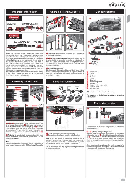
Car components<br />
1 2<br />
1<br />
EVOLUTION<br />
Carrera DIGITAL 132<br />
3 4<br />
8<br />
3<br />
11<br />
Carrera DIGITAL 132<br />
EVOLUTION<br />
3<br />
2<br />
3<br />
10<br />
9<br />
3<br />
4<br />
Please note that Evolution (analog system) and Carrera DIGIT-<br />
AL 132 (digital system) involve two separate and completely independent<br />
systems. We hereby expressly indicate that both systems<br />
must be kept separate when setting up the track, i.e. no connecting<br />
rail from Evolution may be used together with the connecting rail<br />
and Black Box of the Carrera DIGITAL 132, even if only one of the<br />
two connecting rails (Evolution connecting rail or Carrera DIGIT-<br />
AL 132 connecting rail and Black Box) is attached to the current<br />
supply. Furthermore, no other Carrera DIGITAL 132 components<br />
(switches, electronic lap counter, Pit Lane) may be built into an Evolution<br />
course, i.e. via analog operation.<br />
Non-compliance with the above information may result in damage<br />
or destruction of the respective Carrera DIGITAL 132 components.<br />
In this case no warranty may be claimed.<br />
Assembly instructions<br />
1 4<br />
1 Guard rails: Guard rail mounts are fitted by tilting them upwards<br />
onto the verge of the track.<br />
2 + 3 Supporting raised sections: The shank of the ball pivot is<br />
to be inserted into the square slots provided on the underside of the<br />
track. The supports can be made higher by using the extensions.<br />
The pedestal of the supports can be screwed to a base if required<br />
(screws not included).<br />
4 Supporting steep curves:<br />
Slanting supports of the right height are provided to support steep<br />
curves. Fix the nonadjustable supports at the beginning and end of<br />
the curves. Insert the heads of the supports in the round slots of the<br />
underside of the track.<br />
1<br />
Electrical connection<br />
5<br />
7<br />
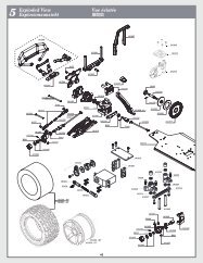
1 Body, spoiler<br />
2 Engine<br />
3 Tyres<br />
4 Rear axle<br />
5 Chassis<br />
6 Guide keel<br />
7 Double sliding contact<br />
8 Front axle<br />
9 Car board with reversing switch<br />
10 Front light board<br />
11 Rear light board<br />
6<br />
Note: vehicle construction depends on the model.<br />
The designation of the individual parts may not be used as<br />
order numbers.<br />
2 3<br />
2<br />
Preparation of start<br />
1 2<br />
1 + 2 + 3 Before assembling please insert the connecting clips<br />
in the track as shown in figure 1 . Stick tracks together on a flat<br />
base. Move the connecting clips according to figure 2 in direction<br />
of the arrow until they audibly snap in. The connecting clip may also<br />
be inserted later. The connecting clips can be removed into both<br />
directions by simply pressing down the clamped nose (see fig. 3 ).<br />
4 Fastening: To fasten the track sections on a board, it is necessary<br />
to use the track section fasteners (Item no. 85209, not contained<br />
in the package).<br />
Note:<br />
Carpeting is not a suitable foundation on which to build the track because<br />
of static charging, formation of fluff and ready inflammability.<br />
1 Connect the transformer plug with the Black Box<br />
2 Connect the enclosed speed controllers to the Black Box<br />
Note: To avoid short-circuits and electrocution, the toy may not be<br />
connected using foreign devices, plugs, cables or other objects foreign<br />
to this toy. The Carrera DIGITAL 132 car racetrack only works<br />
properly with an original Carrera DIGITAL 132 transformer.<br />
The PC interface (PC Unit) may only be operated together with the<br />
original Carrera PC Unit.<br />
This Carrera DIGITAL 132 vehicle ideally matches the Carrera track<br />
system scale 1:24.<br />
1 + 2 Optimally setting up the grinders:<br />
To ensure proper and continuous driving, slightly fan out the ends<br />
of the contact brushes 1 and bend them towards the track as per<br />
fig. 2 . Only the end of the contact brush should have contact to the<br />
track and may be cut off slightly in case of wear. Dust and abrasion<br />
should be removed from track material and sliding contacts from<br />
time to time.<br />
During operation small car parts as spoilers or mirrors may get off or<br />
brake due to being original detailed parts of the car model. To avoid<br />
this it is possible to remove them before operation.<br />
9