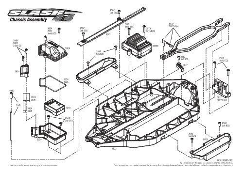
Chassis Assembly - Stanbridges
Chassis Assembly - Stanbridges
Chassis Assembly - Stanbridges

You also want an ePaper? Increase the reach of your titles
YUMPU automatically turns print PDFs into web optimized ePapers that Google loves.
2582<br />
3x6 BCS<br />
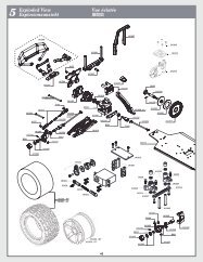
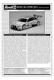
<strong>Chassis</strong> <strong>Assembly</strong><br />
3924<br />
2577<br />
3x10 BCS<br />
2582<br />
3x6 BCS<br />
6841<br />
2579<br />
3x15 BCS<br />
2579<br />
3x15 BCS<br />
5827<br />
5827x Opt.<br />
3924<br />
3965<br />
2.5x8 CS<br />
3924<br />
2582<br />
3x6 BCS<br />
3355X<br />
2582<br />
3x6 BCS<br />
2553<br />
3x15 CCS<br />
6877<br />
3924<br />
3924<br />
3925<br />
1926<br />
3924<br />
3925<br />
5827<br />
5827X Opt.<br />
1726<br />
3924<br />
3925<br />
2218<br />
2534<br />
3x6 CCS<br />
2582<br />
3x6 BCS<br />
3924<br />
2582<br />
3x6 BCS<br />
5823<br />
6822<br />
See Parts List for a complete listing of optional accessories.<br />
REV 100408-R02<br />
Specifications on this page are subject to change without notice.<br />
Every attempt has been made to ensure the accuracy of this drawing, however Traxxas cannot be held responsible for typographical or other errors.
Center Driveline <strong>Assembly</strong><br />
2575<br />
3x6 BCS<br />
6888<br />
4x3 GS<br />
6884<br />
Optional Center Diff<br />
6883<br />
6884<br />
Flat side<br />
against gear<br />
6884<br />
6884<br />
2524<br />
2.5x8 CCS<br />
6877<br />
6877A<br />
2550<br />
3x8 CCS<br />
3943<br />
2743<br />
3x4 GS<br />
3943<br />
6888<br />
2575<br />
BCS 3x6<br />
3956R-54T<br />
6842R-50T<br />
6843R-52T<br />
6883<br />
6884<br />
Flat side<br />
against gear<br />
6860<br />
3932<br />
3x6 FCS<br />
6890<br />
6890X<br />
2550<br />
3x8 CCS<br />
3354<br />
3351<br />
5142<br />
3x15 CS<br />
2577<br />
3x10 BCS<br />
6860<br />
2745<br />
3.0 NL<br />
3x8 BCS<br />
5119<br />
10x15x4 BB<br />
2577<br />
3x10 BCS<br />
6893<br />
5552X<br />
6893<br />
6860<br />
6860X<br />
5556<br />
5351 opt.<br />
6855<br />
6893<br />
6893X opt.<br />
5116<br />
5x11x4 BB<br />
5556<br />
5351 opt.<br />
5552X<br />
5352X opt.<br />
6822<br />
6888<br />
6888<br />
4x3 GS<br />
5552X<br />
2554<br />
3x6 CS<br />
3956 54T<br />
6842 50T opt.<br />
6843 52T opt.<br />
6829<br />
5552X<br />
5.0L<br />
3837<br />
4x12 BCS<br />
See Parts List for a complete listing of optional accessories.<br />
REV 100115-R02<br />
Specifications on this page are subject to change without notice.<br />
Every attempt has been made to ensure the accuracy of this drawing, however Traxxas cannot be held responsible for typographical or other errors.
3932<br />
3x6 FCS<br />
Front <strong>Assembly</strong><br />
3932<br />
3x6 FCS<br />
2746<br />
3x6x0.5 MW<br />
6815<br />
2577<br />
3x10 BCS<br />
3647<br />
NL M4x0.7 Flanged<br />
1747R<br />
1654<br />
1654X opt.<br />
1985<br />
5x8x0.5 TW<br />
5119<br />
10x15x4 BB<br />
5116<br />
5x11x4<br />
6837<br />
6837X opt.<br />
2579<br />
3x15 BCS<br />
3642X<br />
3x12 CSS<br />
3642X<br />
3x12 CSS<br />
3655X<br />
2754<br />
6832<br />
6832X opt.<br />
6834<br />
28mm<br />
2579<br />
3x15 BCS<br />
6851<br />
5539<br />
3643<br />
6828<br />
5525<br />
5525<br />
5119<br />
10x15x4 BB<br />
3937<br />
4x12 BCS<br />
5381<br />
5117<br />
6x12x4 BB<br />
5379X<br />
3936<br />
4x10 BCS<br />
6888X<br />
6845<br />
2582<br />
3x6 BCS<br />
6881<br />
2075<br />
2579<br />
3x15 BCS<br />
3642X<br />
3x12 CSS<br />
2579<br />
3x15 BCS<br />
2576<br />
3x8 BCS<br />
2579<br />
3x15 BCS<br />
6839<br />
2577<br />
3x10 BCS<br />
See Tire/Wheel chart for product options<br />
6815<br />
6815<br />
2576<br />
3x8 BCS<br />
6835<br />
6834<br />
52mm<br />
2579<br />
3x15 BCS<br />
6823<br />
6882<br />
6881<br />
5381<br />
6882<br />
5379X<br />
2579<br />
3x15 BCS<br />
3965<br />
2.5x8 CS<br />
5118<br />
8x16x5 BB<br />
6828<br />
3643<br />
6851<br />
5525<br />
2754<br />
5119<br />
10x15x4 BB<br />
6857<br />
Shock <strong>Assembly</strong><br />
3936<br />
4x10 BCS<br />
3767<br />
3767A opt.<br />
3767X opt.<br />
1765<br />
E<br />
3768<br />
E<br />
Limiter<br />
(rear only)<br />
1664<br />
1664T<br />
6835<br />
2579<br />
3x15 BCS<br />
6834<br />
52mm<br />
1552<br />
3x8 CS<br />
6845<br />
3x6x.05 MW<br />
5114<br />
5x8 BB<br />
6845<br />
3967<br />
3x10 CSS<br />
6845<br />
3655X<br />
1552<br />
3x8 CS<br />
*<br />
6834<br />
28mm<br />
2746<br />
3x6x.05 MW<br />
5114<br />
5x8 BB<br />
6845<br />
2579<br />
3x15 BCS<br />
2579<br />
3x15 BCS<br />
3642X<br />
3x12 CCS<br />
6832<br />
6832X opt.<br />
3642X<br />
3x12 CCS<br />
6837<br />
6837X opt.<br />
5116<br />
5x11x4 BB<br />
1985<br />
5x8x0.5 TW<br />
1654<br />
1654X opt.<br />
*<br />
5539 5525 6845<br />
3647<br />
NL M4x0.7 Flanged<br />
1747R<br />
3768<br />
2362<br />
3765A<br />
3769<br />
6830<br />
1942<br />
2742X<br />
2535<br />
4x10 CCS<br />
See Parts List for a complete listing of optional accessories.<br />
2542<br />
4x12 CCS<br />
2553<br />
3x15 CCS<br />
5114<br />
5x8 BB<br />
2553<br />
3x15 CCS<br />
6845<br />
5114<br />
5x8 BB<br />
Install with rim facing upward.<br />
REV 100414-R02<br />
Specifications on this page are subject to change without notice.<br />
Every attempt has been made to ensure the accuracy of this drawing, however Traxxas cannot be held responsible for typographical or other errors.
6815<br />
Shocks <strong>Assembly</strong><br />
Rear <strong>Assembly</strong><br />
2746<br />
3x6x0.5 MW<br />
6815<br />
2576<br />
3x8 BCS<br />
2577<br />
3x10 BCS<br />
2576<br />
3x8 BCS 2577<br />
3x10 BCS<br />
2578<br />
6858<br />
3767<br />
3767A opt.<br />
3767X opt.<br />
Limiter<br />
(rear only)<br />
2656<br />
2656T<br />
1985<br />
5x8x0.5 TW<br />
3647<br />
NL M4x0.7 Flanged<br />
1747R<br />
6834<br />
28mm<br />
1654<br />
1654X<br />
5116<br />
5x11x4 BB<br />
1952<br />
1952X<br />
1985<br />
5x8x0.5 TW<br />
2754<br />
3655X<br />
5525<br />
6852<br />
2579<br />
3x15 BCS<br />
3644<br />
6828<br />
5118<br />
8x16x5 BB<br />
3642X<br />
3x12 CSS<br />
3965<br />
2.5x8 CS<br />
3642X<br />
3x12 CSS<br />
6879<br />
5381<br />
2579<br />
3x15 BCS<br />
6880<br />
6838<br />
2580<br />
3x20 BCS<br />
2579<br />
3x15 BCS<br />
6834<br />
52mm<br />
6836<br />
6823<br />
6836<br />
2580<br />
3x20 BCS<br />
Rear Only<br />
5529<br />
See Tire/Wheel chart for product options<br />
3766A<br />
Use #1666 silicone<br />
shock oil<br />
3965<br />
2.5x8 CS<br />
5381<br />
6822<br />
6880<br />
6882<br />
6879<br />
5120<br />
12x18x4 BB<br />
6828<br />
5119<br />
10x15x4 BB<br />
6852<br />
5525<br />
3644<br />
2754<br />
2579<br />
3x15 BCS<br />
1985<br />
5x8x0.5 TW<br />
3655X<br />
5116<br />
5x11x4 BB<br />
1952<br />
1952X opt.<br />
1985<br />
5x8x0.5 TW<br />
1654<br />
1654X<br />
3647<br />
1747R<br />
NL M4x0.7 Flanged<br />
6829<br />
2552<br />
3x12 CCS<br />
5116<br />
5x11x4 BB<br />
See Parts List for a complete listing of optional accessories.<br />
3937<br />
4x12 BCS<br />
2551<br />
3x10 CCS<br />
6834<br />
28mm<br />
REV 100816-R02<br />
Specifications on this page are subject to change without notice.<br />
Every attempt has been made to ensure the accuracy of this drawing, however Traxxas cannot be held responsible for typographical or other errors.
Driveshafts<br />
6828<br />
6850<br />
Rear Driveshaft <strong>Assembly</strong><br />
Available fully assembled as part #6852 Available fully assembled as part #6851<br />
6828<br />
6850<br />
Front Driveshaft <strong>Assembly</strong><br />
6850<br />
6850<br />
6850<br />
6850<br />
6854<br />
6853<br />
Modular <strong>Assembly</strong><br />
3936<br />
4x10 BCS<br />
3937<br />
4x12 BCS<br />
3937<br />
4x12 BCS<br />
1985<br />
5x8x0.5 TW<br />
3937<br />
4x12 BCS<br />
2579<br />
3x15 BCS<br />
REV 100105-R02<br />
Specifications on this page are subject to change without notice. Some parts listed are optional accessories. Every attempt has<br />
been made to ensure the accuracy of this drawing, however Traxxas cannot be held responsible for typographical or other errors.
owner’ s manual<br />
MODEL 6808
INTRODUCTION<br />
TABLE OF CONTENTS<br />
3 BEFORE YOU<br />
PROCEED<br />
4 SAFETY<br />
PRECAUTIONS<br />
5 TOOLS, SUPPLIES AND<br />
REQUIRED EQUIPMENT<br />
6 SLASH 4x4<br />
7 QUICK START:<br />
GETTING UP TO SPEED<br />
8 TQ 2.4GHz RADIO AND<br />
VELINEON BRUSHLESS<br />
POWER SYSTEM<br />
16 ADJUSTING THE<br />
ELECTRONIC SPEED<br />
CONTROL<br />
18 DRIVING YOUR MODEL<br />
20 BASIC TUNING<br />
ADJUSTMENTS<br />
22 MAINTAINING<br />
YOUR MODEL<br />
24 ADVANCED TUNING<br />
ADJUSTMENTS<br />
28 TQ 2.4GHz ADVANCED<br />
TUNING GUIDE<br />
Thank you for purchasing the Slash 4X4 equipped with the<br />
Velineon ® Brushless Power System. The Velineon Power System<br />
lets you experience the best that brushless motor technology has<br />
to offer. Incredible speed, efficient operation, long run times, and<br />
low-maintenance operation are just some of the benefits. We are<br />
confident you will be rewarded with high-speed performance in a<br />
durable, long-lasting product.<br />
This manual contains the instructions you will need to operate and<br />
maintain your model so that you can enjoy it for years to come.<br />
We want you to feel confident that you own one of the bestperforming<br />
models in the market and that it is backed by a team<br />
of professionals who aim to provide the highest level of factory<br />
support possible. Traxxas models are about experiencing total<br />
performance and satisfaction, not just with your model, but also<br />
with the company that stands behind it.<br />
We know you’re excited about getting your new model on<br />
the road, but it’s very important that you take some time to<br />
read through the Owner’s Manual. This manual contains all the<br />
necessary set-up and operating procedures that will allow you to<br />
unlock the performance potential that Traxxas engineers designed<br />
into your model. Also be sure to read and follow the precautions<br />
and warnings in this manual and on any labels or tags attached to<br />
your model. They are there to educate you on how to operate your<br />
model safely and also get maximum life and performance from<br />
your model.<br />
Even if you are an experienced R/C enthusiast, it’s important to<br />
read and follow the procedures in this manual.<br />
Thank you again for going with Traxxas. We work hard every day<br />
to assure you receive the highest level of customer satisfaction<br />
possible. We truly want you to enjoy your new model!<br />
Traxxas Support<br />
Traxxas support is with you every step of the<br />
way. Refer to the next page to find out how to<br />
contact us and what your support options are.<br />
Quick Start<br />
This manual is designed with a Quick<br />
Start path that outlines the necessary<br />
procedures to get your model up<br />
and running in the shortest time possible. If you are an<br />
experienced R/C enthusiast you will find it helpful and fast.<br />
Be sure and read through the rest of the manual to learn<br />
about important safety, maintenance, and adjustment<br />
procedures. Turn to page 7 to begin.<br />
2 • SLASH 4x4
BEFORE YOU PROCEED<br />
Carefully read and follow all instructions in this and any<br />
accompanying materials to prevent serious damage to your<br />
model. Failure to follow these instructions will be considered<br />
abuse and/or neglect.<br />
Before running your model, look over this entire manual and<br />
examine the model carefully. If for some reason you decide it is not<br />
what you wanted, then do not continue any further. Your hobby<br />
dealer absolutely cannot accept a model for return or exchange<br />
after it has been run.<br />
WARNINGS, HELPFUL HINTS, & CROSS-REFERENCES<br />
Throughout this manual, you’ll notice warnings and helpful hints<br />
identified by the icons below. Be sure to read them!<br />
An important warning about personal safety or avoiding<br />
damage to your model and related components.<br />
Special advice from Traxxas to make things easier<br />
and more fun.<br />
Refers you to a page with a related topic.<br />
SUPPORT<br />
If you have any questions about your model or its operation,<br />
call the Traxxas Technical Support line toll-free at:<br />
1-888-TRAXXAS (1-888-872-9927)*<br />
Technical support is available Monday through Friday from<br />
8:30am to 9:00pm central time. Technical assistance is also available<br />
at Traxxas.com/support. You may also e-mail customer support with<br />
your question at support@Traxxas.com. Join thousands of registered<br />
members in our online community at Traxxas.com.<br />
Traxxas offers a full-service, on-site repair facility to handle any<br />
of your Traxxas service needs. Maintenance and replacement<br />
parts may be purchased directly from Traxxas by phone or online<br />
at BuyTraxxas.com. You can save time, along with shipping<br />
and handling costs, by purchasing replacement parts from your<br />
local dealer.<br />
Do not hesitate to contact us with any of your product support needs.<br />
We want you to be thoroughly satisfied with your new model!<br />
Traxxas<br />
1100 Klein Road<br />
Plano, Texas 75074<br />
Phone: 972-265-8000<br />
Toll-free 1-888-TRAXXAS<br />
Traxxas U.K.<br />
P.O. Box 1128<br />
Winterbourne, Bristol<br />
BS36-2SH<br />
England<br />
Phone: 44-117-956-1002<br />
Internet<br />
Traxxas.com<br />
E-mail: support@Traxxas.com<br />
Entire contents ©2010 Traxxas.<br />
Traxxas, Ready-To-Race, Ready-<br />
To-Win, Slash, Velineon and<br />
ProGraphix are trademarks or<br />
registered trademarks of Traxxas.<br />
Other brand names and marks are<br />
the property of their respective<br />
holders and are used only for<br />
purposes of identification. No<br />
part of this manual may be<br />
reproduced or distributed in print<br />
or electronic media without the<br />
express written permission of<br />
Traxxas. Specifications are subject<br />
to change without notice.<br />
*Toll-free support is available to U.S. residents only.<br />
SLASH 4x4 • 3
SAFETY PRECAUTIONS<br />
All instructions and<br />
precautions outlined in this<br />
manual should be strictly<br />
followed to ensure safe<br />
operation of your model.<br />
This model is not intended<br />
for use by children under<br />
14 years of age without the<br />
supervision of a responsible<br />
and knowledgeable adult.<br />
Gearing and battery choice<br />
(see LiPo Batteries, right)<br />
effect the skill level of the<br />
model. See chart below.<br />
4 • SLASH 4x4<br />
Gearing: Stock Pinion<br />
Battery: 7-Cell NiMH<br />
Voltage * : 8.4V<br />
mAh: 3000+mAh<br />
Gearing: Opt. Pinion<br />
Battery: 7-Cell NiMH<br />
Voltage * : 8.4V<br />
mAh: 3000+mAh<br />
Gearing: Stock Pinion<br />
Battery: 3S 20C LiPo<br />
Voltage * : 11.1V<br />
mAh: 5000+ mAh<br />
Gearing: Opt. Gearing<br />
Battery: 3S 20C LiPo<br />
Voltage * : 11.1V<br />
mAh: 5000+ mAh<br />
*Nominal<br />
See the gearing chart on page<br />
24 for more information.<br />
1<br />
All of us at Traxxas want you to safely enjoy your new model. Operate your model<br />
sensibly and with care, and it will be exciting, safe, and fun for you and those<br />
around you. Failure to operate your model in a safe and responsible manner may<br />
result in property damage and serious injury. The precautions outlined in this<br />
manual should be strictly followed to help ensure safe operation. You alone must<br />
see that the instructions are followed and the precautions are adhered to.<br />
IMPORTANT POINTS TO REMEMBER<br />
• Your model is not intended for use on public roads or congested areas where its<br />
operation can conflict with or disrupt pedestrian or vehicular traffic.<br />
• Never, under any circumstances, operate the model in crowds of people. Your<br />
model is very fast and could cause injury if allowed to collide with anyone.<br />
• Because your model is controlled by radio, it is subject to radio interference from<br />
many sources that are beyond your control. Since radio interference can cause<br />
momentary losses of radio control, always allow a safety margin in all directions<br />
around the model in order to prevent collisions.<br />
• The motor, battery, and speed control can become hot during use. Be careful to<br />
avoid getting burned.<br />
• Don’t operate your model at night, or anytime your line of sight to the model<br />
may be obstructed or impaired in any way.<br />
• Most importantly, use good common sense at all times.<br />
BATTERIES AND BATTERY CHARGING<br />
Your model uses rechargeable batteries that must be handled with care for safety<br />
and long battery life. Make sure to read and follow all instructions and precautions<br />
for charging and maintaining the batteries. It is your responsibility to charge<br />
and care for the battery packs properly. In addition to your battery and charger<br />
instructions, here are some more tips to keep in mind.<br />
• Use the supplied charger to charge the included battery. See “Charging your<br />
Battery Pack” on page 11.<br />
• Never leave batteries to charge unattended.<br />
• Remove the battery from the model while charging.<br />
• Always unplug the battery from the electronic speed control when the model is<br />
not in use and when it is being stored or transported.<br />
• Allow the battery pack to cool off between runs (before charging).<br />
• Children should have responsible adult supervision when charging and handling<br />
batteries.<br />
• Do not use battery packs that have been damaged in any way.<br />
• Do not use battery packs that have damaged wiring, exposed wiring, or a<br />
damaged connector.<br />
• Only use approved chargers for NiMH battery packs (such as the Traxxas EZ-Peak <br />
Charger, Part #2930). Do not exceed the maximum charge rate of 4 amps.<br />
• Do not short-circuit the battery pack. This may cause burns and severe damage to<br />
the battery pack.<br />
• Do not burn or puncture the batteries. Toxic materials could be released. If eye or<br />
skin contact occurs, flush with water.<br />
• Store the battery pack in a dry location, away from heat sources and direct sunlight.<br />
• Nickel Metal Hydride batteries must be recycled or disposed of properly.<br />
Recycling Your Traxxas Power Cell NiMH Battery<br />
Traxxas strongly encourages you to recycle your Power Cell battery when it<br />
has reached the end of its useful life. Do not throw your battery in the trash.<br />
All Power Cell battery packs display the RBRC (Rechargeable Battery Recycling<br />
Corporation) icon, indicating they are recyclable. To find a recycling center near<br />
you, ask your local hobby dealer or visit www.rbrc.org.<br />
LiPo Batteries<br />
Lithium Polymer (LiPo) batteries are becoming popular for use in R/C models due<br />
to their compact size, high energy density, and high-current output. However,<br />
these types of batteries require special care and handling<br />
procedures for long life and safe operation. Warning: LiPo batteries are intended<br />
only for advanced users that are educated on the risks associated with LiPo battery<br />
use. Traxxas does not recommend that anyone under the age of 16 use or<br />
handle LiPo battery packs without the supervision of a knowledgeable and<br />
responsible adult.<br />
Your model is able to use LiPo batteries with nominal voltage not to exceed 11.1<br />
volts (3S packs). LiPo batteries have a minimum safe discharge voltage threshold<br />
that should not be exceeded. The Velineon VXL-3s electronic speed control is<br />
equipped with built-in Low-Voltage Detection that alerts the driver when LiPo<br />
batteries have reached their minimum voltage (discharge) threshold. It is the<br />
driver’s responsibility to stop immediately to prevent the battery pack from<br />
being discharged below its safe minimum threshold.<br />
Low-Voltage Detection on the speed control is just one part of a comprehensive<br />
plan for safe LiPo battery use. It is critical for you, the user, to follow all<br />
other instructions supplied by the battery manufacturer and the charger<br />
manufacturer for proper charging, use, and storage of LiPo batteries. Do not<br />
attempt to charge LiPo batteries with the Traxxas charger included in this<br />
package. Make sure you understand how to use your LiPo batteries. Be aware<br />
that Traxxas shall not be liable for any special, indirect, incidental, or consequential<br />
damages arising out of the installation and/or use of LiPo batteries in Traxxas<br />
models. If you have questions about LiPo battery usage, please consult with<br />
your local hobby dealer or contact the battery manufacturer. As a reminder, all<br />
batteries should be recycled at the end of their useful life.<br />
SPEED CONTROL<br />
• Disconnect the Batteries: Always disconnect the battery pack from<br />
the speed control when not in use.<br />
• Transmitter on First: Switch on your transmitter first before switching on the<br />
speed control to prevent runaways and erratic performance.<br />
• Don’t Get Burned: The heat sink can get extremely hot, so be careful not to touch<br />
it until it is cool. Supply adequate airflow for cooling.<br />
• Use Stock Connectors: If you decide to change the battery or motor connectors,<br />
only change one battery or motor connector at a time. This will prevent damage<br />
from accidentally mis-wiring the speed control. Please note that modified speed<br />
controls can be subject to a rewiring fee when returned for service. Removing the<br />
battery connector on the speed control or using the same-gender connectors on<br />
the speed control will void the product’s warranty.<br />
• Insulate the Wires: Always insulate exposed or damaged wiring with heat shrink<br />
tubing to prevent short circuits
TOOLS, SUPPLIES AND REQUIRED EQUIPMENT<br />
Your model comes with a set of specialty metric tools. You’ll need to purchase other items, available from your hobby dealer, to operate and<br />
maintain your model.<br />
Supplied Tools and Equipment<br />
For more information on<br />
batteries, see Use the Right<br />
Batteries on page 11.<br />
2.5mm “L” wrench<br />
Body clips and body<br />
washers<br />
2.0mm “L” wrench<br />
Optional Pinion<br />
Gear see page 24<br />
1.5mm “L” wrench<br />
U-joint wrench<br />
Various pre-load spacers and shock<br />
pistons (on plastic tree) see page 21<br />
8mm/4mm wrench<br />
Foam battery spacer for 6-cell<br />
or small battery packs<br />
4-way wrench<br />
Recommended Equipment<br />
These items are not required<br />
for the operation of your<br />
model, but are a good idea to<br />
include in any R/C toolbox:<br />
• Safety glasses<br />
• Thin, hobby-quality<br />
cyanoacrylate instant tire<br />
glue (CA glue)<br />
• Hobby knife<br />
• Side cutters and/or needle<br />
nose pliers<br />
• Philips screwdriver<br />
• Soldering iron<br />
Required Equipment<br />
(sold separately)<br />
NiMH battery charger*<br />
7-cell NiMH battery pack with<br />
Traxxas High-Current Connector*<br />
4 AA alkaline<br />
batteries<br />
*Battery and charger style are subject to change and may vary from images.<br />
SLASH 4x4 • 5
ANATOMY OF THE SLASH 4X4<br />
Half Shaft<br />
Turnbuckle<br />
(Rear Camber Link)<br />
Rear<br />
Body Mount<br />
Spur Gear<br />
Battery Compartment<br />
Battery Hold-Down<br />
Battery<br />
Traxxas High-Current<br />
Connector<br />
Front<br />
Suspension Arm<br />
Front Body<br />
Mount<br />
<strong>Chassis</strong><br />
Drive Shaft<br />
Steering Block<br />
(Axle Carrier)<br />
Caster Block<br />
(C-Hub)<br />
Front<br />
Shock Tower<br />
Front Bumper<br />
Rear Bumper<br />
Rear Shock Tower<br />
Motor<br />
(Velineon 3500)<br />
Receiver Box<br />
Shock<br />
(Oil Damper)<br />
Rear Suspension Arm<br />
Pinion Gear<br />
Electronic Speed<br />
Control (VXL-3s)<br />
Steering Servo<br />
Antenna Mount<br />
Turnbuckle<br />
(Front Camber Link)<br />
6 • SLASH 4x4<br />
Slipper Clutch<br />
Nerf Bar<br />
Turnbuckle (Toe Link)<br />
Half Shaft
QUICK START: GETTING UP TO SPEED<br />
The following guide is an overview of the procedures for getting your model running. Look for the Quick Start logo on the bottom<br />
corners of Quick Start pages.<br />
1. Read the safety precautions on page 4 6. Check servo operation • See page 14<br />
For your own safety, understand where carelessness and misuse Make sure the steering servo is working correctly.<br />
could lead to personal injury and product damage.<br />
2. Charge the battery pack • See page 11 7. Range test the radio system • See page 14<br />
Fully charge the included battery pack. Begin charging<br />
your battery right away.<br />
Follow this procedure to make sure your radio system works properly at<br />
a distance and that there is no interference from outside sources.<br />
The Quick Start Guide is<br />
not intended to replace the<br />
full operating instructions<br />
available in this manual.<br />
Please read this entire<br />
manual for complete<br />
instructions on the proper<br />
use and maintenance of<br />
your model.<br />
3. Install batteries in the transmitter • See page 11 8. Detail your model • See sidebar, page 8<br />
The transmitter requires 4 AA alkaline or rechargeable batteries.<br />
Apply other decals if desired.<br />
4. Install the battery pack in the model • See page 12 9. Drive your model • See page 18<br />
Your model requires a fully charged battery pack.<br />
Driving tips and adjustments for your model.<br />
5. Turn on the radio system • See page 13 10. Maintaining your model • See page 22<br />
Make a habit of turning the transmitter on first, and off last.<br />
Follow these critical steps to maintain the performance<br />
of your model and keep it in excellent running condition.<br />
Look for the Quick Start<br />
logo at the bottom of<br />
Quick Start pages.<br />
SLASH 4x4 • 7
TRAXXAS TQ 2.4GHz RADIO & VELINEON Power SYSTEM<br />
Applying the Decals<br />
The main decals for your<br />
model have been applied at<br />
the factory. The decals are<br />
printed on self-adhesive clear<br />
mylar and are die-cut for easy<br />
removal. Use a hobby knife to<br />
lift the corner of a decal and<br />
lift it from the backing.<br />
To apply the decals, place<br />
one end down, hold the<br />
other end up, and gradually<br />
smooth the decal down with<br />
your finger as you go. This<br />
will prevent air bubbles.<br />
Placing both ends of the<br />
decal down and then trying<br />
to smooth it out will result<br />
in air pockets. Look at the<br />
photos on the box for typical<br />
decal placement.<br />
8 • SLASH 4x4<br />
8<br />
INTRODUCTION<br />
Your model includes the latest Traxxas TQ 2.4GHz transmitter<br />
with Traxxas Link technology. The transmitter’s easy-to-use<br />
design provides instant driving fun for new R/C enthusiasts,<br />
and also offers a full compliment of pro-level tuning features<br />
for advanced users – or anyone interested in experimenting<br />
with the performance of their model. The steering and throttle<br />
channels feature adjustable Exponential, End Points, and Sub-<br />
Trims. Steering and braking Dual Rate are also available. Many of<br />
the next-level features are controlled by the Multi-Function knob,<br />
which can be programmed to control a variety functions. The<br />
detailed instructions (page 28) and Menu Tree (page 30) included<br />
in this manual will help you understand and operate the advanced<br />
functions of the new TQ 2.4GHz radio system. For additional<br />
information and how-to videos, visit Traxxas.com.<br />
RADIO AND POWER SYSTEM TERMINOLOGY<br />
Please take a moment to familiarize yourself with these radio and<br />
power system terms. They will be used throughout this manual.<br />
A detailed explanation of the advanced terminology and features<br />
of your new radio system begins on page 28.<br />
2.4GHz Spread Spectrum – This model is equipped with the latest<br />
R/C technology. Unlike AM and FM systems that require frequency<br />
crystals and are prone to frequency conflicts, the TQ 2.4GHz system<br />
automatically selects and locks onto an open frequency, and offers<br />
superior resistance to interference and “glitching.”<br />
BEC (Battery Eliminator Circuit) - The BEC can either be in the<br />
receiver or in the ESC. This circuit allows the receiver and servos<br />
to be powered by the main battery pack in an electric model.<br />
This eliminates the need to carry a separate pack of 4 AA<br />
batteries to power the radio equipment.<br />
Brushless Motor - A D/C brushless motor replaces the brushed<br />
motor’s traditional commutator and brush arrangement with<br />
intelligent electronics that energize the electromagnetic<br />
windings in sequence to provide rotation. Opposite of a brushed<br />
motor, the brushless motor has its windings (coils) on the<br />
perimeter of the motor can and the magnets are mounted to the<br />
spinning rotor shaft.<br />
Cogging - Cogging is a condition sometimes associated with<br />
brushless motors. Typically it is a slight stutter noticed when<br />
accelerating from a stop. It happens for a very short period as<br />
the signals from the electronic speed control and the motor<br />
synch with each other. The VXL-3s electronic speed control is<br />
optimized to virtually eliminate cogging.<br />
Current - Current is a measure of power flow through the<br />
electronics, usually measured in amps. If you think of a wire as a<br />
garden hose, current is a measure of how much water is flowing<br />
through the hose.<br />
ESC (Electronic Speed Control) - An electronic speed control is the<br />
electronic motor control inside the model. The VXL-3s electronic<br />
speed control uses advanced circuitry to provide precise, digital<br />
proportional throttle control. Electronic speed controls use<br />
power more efficiently than mechanical speed controls so that<br />
the batteries run longer. An electronic speed control also has<br />
circuitry that prevents loss of steering and throttle control as the<br />
batteries lose their charge.<br />
Frequency band - The radio frequency used by the transmitter to<br />
send signals to your model. This model operates on the 2.4GHz<br />
direct-sequence spread spectrum.<br />
kV Rating - Brushless motors are often rated by their kV number.<br />
The kV rating equals no-load motor rpm with 1 volt applied. The<br />
kV increases as the number of wire turns in the motor decreases.<br />
As the kV increases, the current draw through the electronics<br />
also increases. The Velineon 3500 motor is a 10-turn, 3500 kV<br />
motor optimized for the best speed and efficiency in lightweight<br />
1/10 scale models.<br />
LiPo - Abbreviation for Lithium Polymer. Rechargeable LiPo<br />
battery packs are known for their special chemistry that allows<br />
extremely high energy density and current handling in a<br />
compact size. These are high performance batteries that require<br />
special care and handling. For advanced users only.<br />
mAh – Abbreviation for milliamp hour. A measure of the capacity<br />
of the battery pack. The higher the number, the longer the<br />
battery will last between recharges.<br />
Neutral position - The standing position that the servos seek<br />
when the transmitter controls are at the neutral setting.<br />
NiCad - Abbreviation for nickel-cadmium. The original<br />
rechargeable hobby pack, NiCad batteries have very high current
TRAXXAS TQ 2.4GHz RADIO & VELINEON Power SYSTEM<br />
handling, high capacity, and can last up to 1000 charging cycles.<br />
Good charging procedures are required to reduce the possibility<br />
of developing a “memory” effect and shortened run times.<br />
NiMH - Abbreviation for nickel-metal hydride. Rechargeable<br />
NiMH batteries offer high current handling, and much greater<br />
resistance to the “memory” effect. NiMH batteries generally<br />
allow higher capacity than NiCad batteries. They can last up to<br />
500 charge cycles. A peak charger designed for NiMH batteries is<br />
required for optimal performance.<br />
Receiver - The radio unit inside your model that receives signals<br />
from the transmitter and relays them to the servos.<br />
Resistance - In an electrical sense, resistance is a measure of how<br />
an object resists or obstructs the flow of current through it.<br />
When flow is constricted, energy is converted to heat and is lost.<br />
The Velineon power system is optimized to reduce electrical<br />
resistance and the resulting power-robbing heat.<br />
Rotor - The rotor is the main shaft of the brushless motor. In a<br />
brushless motor, the magnets are mounted to the rotor, and the<br />
electromagnetic windings are built into the motor housing.<br />
Sensored - Sensored refers to a type of brushless motor that<br />
uses an internal sensor in the motor to communicate rotor<br />
position information back to the electronic speed control. The<br />
VXL-3s electronic speed control is able to use sensored motors<br />
when applications benefit from them (such as some sanctioned<br />
racing classes).<br />
Sensorless - Sensorless refers to a brushless motor that uses<br />
advanced instructions from an electronic speed control to<br />
provide smooth operation. Additional motor sensors and<br />
wiring are not required. The VXL-3s electronic speed control is<br />
optimized for smooth sensorless control.<br />
Servo - Small motor unit in your model that operates the steering<br />
mechanism.<br />
Solder Tabs - Accessible, external contacts on the motor that<br />
allows for easy wire replacement. The Velineon 3500 is equipped<br />
with solder tabs.<br />
Transmitter - The hand-held radio unit that sends throttle and<br />
steering instructions to your model.<br />
Trim - The fine-tuning adjustment of the neutral position of the<br />
servos, made by adjusting the throttle and steering trim knobs<br />
on the face of the transmitter. Note: The Multi Function knob<br />
must be programmed to serve as a throttle trim adjustment.<br />
Thermal Shutdown Protection - Temperature sensing electronics<br />
used in the VXL-3s electronic speed control detect overloading<br />
and overheating of the transistor circuitry. If excessive<br />
temperature is detected, the unit automatically shuts down to<br />
prevent damage to the electronics.<br />
2-channel radio system - The TQ radio system, consisting of<br />
the receiver, the transmitter, and the servos. The system uses<br />
two channels: one to operate the throttle and one to operate<br />
the steering.<br />
Voltage - Voltage is a measure of the electrical potential difference<br />
between two points, such as between the positive battery terminal<br />
and ground. Using the analogy of the garden hose, while current is<br />
the quantity of water flow in the hose, voltage corresponds to the<br />
pressure that is forcing the water through the hose.<br />
IMPORTANT RADIO SYSTEM PRECAUTIONS<br />
For maximum range, always hold the<br />
transmitter so the antenna is in a vertical<br />
position (pointing straight up). The transmitter’s<br />
antenna can be swiveled and angled to allow<br />
for a vertical position if necessary.<br />
Do not kink the receiver’s antenna wire. Kinks<br />
in the antenna wire will reduce range.<br />
DO NOT CUT any part of the receiver’s antenna<br />
wire. Cutting the antenna will reduce range.<br />
Extend the antenna wire in the model as far as possible for<br />
maximum range. It is not necessary to extend the antenna<br />
wire out of the body, but wrapping or coiling the antenna wire<br />
should be avoided.<br />
Do not allow the antenna wire to extend outside the body<br />
without the protection of an antenna tube, or the antenna<br />
wire may get cut or damaged, reducing range. Always keep<br />
the wire protected (in the antenna tube) to prevent the chance<br />
of damage.<br />
Correct<br />
To prevent loss of radio range<br />
do not kink or cut the black wire,<br />
do not bend or cut the metal tip,<br />
and do not bend or cut the white<br />
wire at the end of the metal tip.<br />
No<br />
No<br />
No<br />
SLASH 4x4 • 9
TRAXXAS TQ 2.4GHz RADIO & VELINEON Power SYSTEM<br />
ESC/Motor Wiring Diagram<br />
Your model is equipped with the newest Traxxas 2.4 GHz<br />
transmitter with Traxxas Link. The transmitter has two channels<br />
for controlling your throttle and steering. The receiver inside the<br />
model has 5 output channels. Your model is equipped with one<br />
servo and an electronic speed control.<br />
MODEL WIRING DIAGRAM<br />
Traxxas High-Current<br />
Connector (Male)<br />
to Battery<br />
TQ 2.4GHz Transmitter<br />
Antenna<br />
Receiver<br />
Antenna<br />
Steering Wheel<br />
Multi-Function Knob<br />
Steering<br />
Trim<br />
Throttle Neutral<br />
Adjust<br />
Channel 2<br />
Electronic<br />
Speed Control<br />
Velineon<br />
Brushless Motor<br />
(see side bar for proper<br />
motor wiring)<br />
* Not Used<br />
Channel 1<br />
Steering Servo<br />
Motor Cap<br />
VXL-3s ELECTRONIC SPEED CONTROL<br />
Traxxas High-Current<br />
Connector (Male)<br />
to Battery<br />
Throttle<br />
Trigger<br />
to Motor<br />
Cooling Fan<br />
Connector<br />
(for optional use)<br />
LED<br />
Heat Sink<br />
10 • SLASH 4x4<br />
Power<br />
Switch<br />
Battery<br />
Compartment<br />
Set Button<br />
Menu Button<br />
Red/Green Status LED<br />
see page 29 for more info<br />
Auxiliary Port<br />
(for optional use)<br />
EZ-Set Button<br />
(On/Off Button)<br />
Receiver cable<br />
(RX wire)
TQ 2.4GHz RADIO AND VELINEON POWER SYSTEM<br />
INSTALLING TRANSMITTER BATTERIES<br />
Your TQ transmitter uses 4 AA batteries. The battery compartment<br />
is located in the base of the transmitter.<br />
1. Remove the battery compartment door by pressing the tab<br />
and lifting the door up.<br />
2. Install the batteries in the correct orientation as indicated in<br />
the battery compartment.<br />
3. Reinstall the battery door and snap it closed.<br />
4. Turn on the transmitter and check the status indicator for a solid<br />
green light.<br />
If the status LED flashes red, the transmitter batteries may be<br />
weak, discharged or possibly installed incorrectly. Replace with<br />
new or freshly charged batteries. The power indicator light does<br />
not indicate the charge level of the battery pack installed in the<br />
model. Refer to the Troubleshooting section on page 29 for more<br />
information on the transmitter Status LED codes.<br />
CHARGING THE BATTERY PACK<br />
Use the included charger to charge the included battery pack. The<br />
battery pack should be removed from the vehicle before charging. Do<br />
not leave the battery unattended while charging. It is normal for the<br />
battery to become slightly warm as it nears full-charge, but the battery<br />
should never become hot. If the battery becomes hot, disconnect it from the<br />
charger immediately.<br />
1. Plug the charger into the wall. The LED on the charger should<br />
glow green.<br />
2. Connect the included battery pack to the charger output cord. The<br />
LED will glow red indicating the battery is charging.<br />
3. A completely discharged 3000 mAh battery will charge for<br />
approximately 8 hours with the included charger. The LED will turn<br />
green when the battery is fully charged. Disconnect the battery<br />
from the charger after charging.<br />
1<br />
2 3<br />
Disconnected<br />
Connected<br />
Using Other Chargers<br />
Another convenient option for charging the included battery<br />
is an AC peak-detecting charger that plugs directly into an AC<br />
wall outlet, such as the TRX EZ-Peak (Part #2930). It contains<br />
special peak-detection circuitry that automatically shuts the<br />
charger off when the battery is fully charged.<br />
For faster charging, the included battery may be charged at<br />
4 amps. The TRX EZ-Peak is a 4 amp charger and will charge<br />
the included battery in only 45 minutes!<br />
Caution: Never use a 15-minute timed charger to recharge<br />
your model’s battery packs. Overcharging may result, causing<br />
damage to the battery packs.<br />
Use the Right Batteries<br />
Your transmitter uses<br />
AA batteries. Use new<br />
alkaline batteries, or<br />
rechargeable batteries<br />
such as NiMH (Nickel Metal<br />
Hydride) batteries in your<br />
transmitter. Make sure<br />
rechargeable batteries are<br />
fully charged according<br />
to the manufacturer’s<br />
instructions.<br />
If you use rechargeable<br />
batteries in your<br />
transmitter, be aware<br />
that when they begin<br />
to lose their charge, they<br />
lose power more quickly<br />
than regular alkaline<br />
batteries.<br />
Caution: Discontinue<br />
running your model at the<br />
first sign of weak batteries<br />
(flashing red light on the<br />
transmitter) to avoid losing<br />
control.<br />
If the power indicator doesn’t<br />
light green, check the polarity<br />
of the batteries. Check<br />
rechargeable batteries for<br />
a full charge. If you see any<br />
other flashing signal from the<br />
LED, refer to the chart on page<br />
29 to identify the code.<br />
2, 3<br />
SLASH 4x4 • 11
TQ 2.4GHz RADIO AND VELINEON POWER SYSTEM<br />
The following Traxxas High<br />
Current Connector packages<br />
are available from your<br />
hobby dealer. When using<br />
adapters, be careful not to<br />
exceed the current rating of<br />
the Molex connector.<br />
Part #3060<br />
Single Male/Female<br />
Part #3080<br />
2-Pack Female<br />
INSTALLING THE BATTERY PACK<br />
Install the battery pack with<br />
the battery wires facing the<br />
rear of the model. Insert the<br />
tabs of the battery hold-down<br />
into the slots in the rear holddown<br />
retainer and then place<br />
the battery hold-down over<br />
the post. Secure the battery<br />
hold-down with body clip in<br />
the hole in the post. Do not<br />
connect the battery pack yet.<br />
The Traxxas High Current Connector<br />
Your model is equipped with the patented<br />
Traxxas High-Current Connector. Standard<br />
connectors restrict current flow and are not<br />
capable of delivering the power needed<br />
to maximize the output of the Velineon<br />
Brushless Power system.<br />
The Traxxas connector’s gold-plated terminals with a large contact<br />
surfaces ensure positive current flow with the least amount of<br />
resistance. Secure, long-lasting, and easy to grip, the Traxxas<br />
connector is engineered to extract all the power your battery has<br />
to give.<br />
Part #3061<br />
Male Charge Adapter<br />
Part #3062<br />
Female Charge Adapter<br />
Battery Compartment Specs:<br />
• 166mm (6.54") long<br />
x 49.5mm (1.95") wide<br />
• Height with stock strap:<br />
23mm (.91") or 25mm (.94")<br />
• Height with Part #5827X<br />
options battery standoffs:<br />
Up to 44mm (1.73")<br />
Note: There is some flex with<br />
the battery strap. It is possible<br />
to fit slightly taller batteries in<br />
the compartment.<br />
12 • SLASH 4x4<br />
Part #3070<br />
2-Pack Male<br />
4<br />
Using Different Battery Configuration<br />
The battery hold-down is capable of accommodating either sideby-side<br />
racing style packs, “hump packs” with a stacked seventh<br />
cell, or the more common stick packs. The battery compartment is<br />
configured for stick packs from the factory. The number on each<br />
side of the hold down indicates the battery height in millimeters<br />
that hold-down can accommodate. Note that one side is labeled<br />
“25” and other side is labeled “23”. The 25mm side is for use with<br />
typical stick type battery packs. If you are using side-by-side racing<br />
packs, simply flip the hold-down over to the 23mm side and use it on<br />
the opposite side of the chassis. Note: For taller batteries, an extended<br />
battery hold down, part #5827X, is available (sold separately). For<br />
shorter batteries (6-cell), us the included foam block in the front of the<br />
battery compartment.<br />
25mm side: Standard NiMH stick pack<br />
and “hump Pack” setup<br />
23mm side: Side-by-side NiMH pack setup<br />
Using Other Batteries<br />
Your model is equipped with a state of the art, highperformance<br />
power system. It is designed to be able to flow<br />
large amounts power with the least amount of restriction.<br />
The benefits are drastically increased speed and acceleration.<br />
However, this places extra demands on the battery and<br />
electrical system connections. For best performance, your<br />
model requires the use of NiMH battery packs that have cells<br />
rated for high discharge and use high-quality, low-resistance<br />
assembly techniques, such as the included Traxxas Power<br />
Cell Battery Pack. Cheaply made battery packs do not retain<br />
their performance characteristics after repeated uses in highpowered<br />
electric applications. They will lose their punch and<br />
run time and may require frequent replacement. In addition,<br />
poor-quality, high-resistance cell connectors could fail,<br />
requiring disassembly and repair. The main goal is to reduce<br />
all sources of high resistance in the pack. This includes the<br />
connector, the wire, and the bars attaching the cells together.<br />
High pack resistance will create<br />
additional heat and rob you of the<br />
full power the cells are capable of<br />
producing. We recommend using<br />
Traxxas Power Cell batteries for<br />
best performance.<br />
2923 Battery, Power Cell, 3000mAh (NiMH, 7-C flat, 8.4V)<br />
2940 Battery, Series 3 Power Cell, 3300mAh (NiMH, 7-C flat, 8.4V)<br />
2950 Battery, Series 4 Power Cell, 4200mAh (NiMH, 7-C flat, 8.4V)
TQ 2.4GHz RADIO AND VELINEON POWER SYSTEM<br />
TQ 2.4GHz RADIO SYSTEM CONTROLS<br />
TQ RADIO SYSTEM RULES<br />
Always turn your TQ 2.4GHz transmitter on first and off last. This<br />
procedure will help to prevent your model from receiving stray<br />
signals from another transmitter, or other source, and running out<br />
of control. Your model has electronic fail-safes to prevent this type<br />
of malfunction, but the first, best defense against a runaway model<br />
is to always turn the transmitter on first, and off last.<br />
Always use new or freshly charged batteries for the radio<br />
system. Weak batteries will limit the radio signal between the<br />
receiver and the transmitter. Loss of the radio signal can cause<br />
you to lose control of your model.<br />
1 2<br />
Always turn your<br />
transmitter on first.<br />
Plug in the battery.<br />
3<br />
Turn on the model.<br />
In order for the transmitter and receiver to bind to one another,<br />
the receiver in the model must be turned on within 20 seconds<br />
of turning on the transmitter. The transmitter LED will flash fast<br />
red indicating a failure to link. If you miss it, simply turn off the<br />
transmitter and start over.<br />
Always turn on the transmitter before plugging in the battery.<br />
TQ 2.4GHz Radio System Basic Adjustments<br />
Throttle Neutral Adjustment<br />
The throttle neutral adjustment is located<br />
on the transmitter face and controls the<br />
forward/reverse travel of the throttle trigger.<br />
Change the adjustment by pressing the<br />
button and sliding it to the desired position.<br />
There are two settings available:<br />
50/50: Allows equal travel for both acceleration and reverse.<br />
70/30: Allows more throttle travel (70%) and less reverse travel (30%).<br />
Note: We strongly recommend to leave this control in its factory<br />
location until you become familiar with all the adjustments and<br />
capabilities of your model. To change the throttle neutral adjust<br />
position, turn the transmitter off before adjusting the neutral<br />
position. You will need to reprogram your electronic speed control<br />
to recognize the 70/30 setting. Turn to ESC Setup Programming on<br />
page 16 for instructions.<br />
Steering Trim<br />
The electronic steering trim located on the face of the<br />
transmitter adjusts the neutral (center) point of the<br />
steering channel.<br />
Multi-Function Knob<br />
The Multi-Function knob can be programmed to<br />
control a variety of functions. From the factory, the<br />
Multi-Function knob controls steering sensitivity,<br />
also known as exponential or “expo.” When the<br />
knob is turned counterclockwise all the way to the left (default<br />
position), expo is off and steering sensitivity will be linear (the most<br />
commonly used setting). Turning the knob clockwise will “add<br />
expo” and decrease the steering sensitivity in the initial range of<br />
steering wheel travel left or right from center. For more detail on<br />
steering exponential, refer to page 15.<br />
0<br />
0<br />
100<br />
THROTTLE TRIM<br />
100<br />
Remember, always turn the<br />
TQ transmitter on first and<br />
off last to avoid damage to<br />
your model.<br />
Automatic Fail-Safe<br />
The TQ 2.4GHz transmitter<br />
and receiver are equipped<br />
with an automatic failsafe<br />
system that does not<br />
require user programming.<br />
In the event of signal loss<br />
or interference, the throttle<br />
will return to neutral and<br />
the steering will hold its<br />
last commanded position. If<br />
Fail-Safe activates while you<br />
are operating your model,<br />
determine the reason for<br />
signal loss and resolve the<br />
problem before operating<br />
your model again.<br />
THROTTLE TRIM<br />
When rechargeable batteries<br />
begin to lose their charge,<br />
they will fade much faster<br />
than alkaline dry cells. Stop<br />
immediately at the first sign<br />
of weak batteries. Never turn<br />
the transmitter off when the<br />
battery pack is plugged<br />
in. The model could run out<br />
of control.<br />
5<br />
SLASH 4x4 • 13
TQ 2.4GHz RADIO AND VELINEON POWER SYSTEM<br />
Using Reverse: While driving,<br />
push the throttle trigger<br />
forward to apply brakes.<br />
Once stopped, return the<br />
throttle trigger to neutral.<br />
Push the throttle trigger<br />
forward again to engage<br />
proportional reverse.<br />
14 • SLASH 4x4<br />
6, 7<br />
Using the TQ 2.4GHz Radio System<br />
The TQ 2.4GHz Radio System has been pre-adjusted at the factory. The<br />
adjustment should be checked before running the model, in case of<br />
movement during shipping. Here’s how:<br />
1. Turn the transmitter switch on. The status LED on the transmitter<br />
should be solid green (not flashing).<br />
2. Elevate the model on a block or a stand so that all the tires are<br />
off the ground. Make sure your hands are clear of the moving<br />
parts of the model.<br />
3. Plug the battery pack in the model into the speed control.<br />
4. The on/off switch is integrated into the speed control. With the<br />
transmitter on, press and release the EZ-Set button (.25 seconds).<br />
The LED will shine RED (see note, below). This turns the model<br />
on. To turn the VXL-3s off, press and hold the EZ-Set button<br />
until the LED turns off (.5 seconds). Note: If the LED shines<br />
green, Low-Voltage Detection is activated. This will cause erratic<br />
performance from the included NiMH battery pack. The default<br />
factory setting is for Low-Voltage Detection to be disabled<br />
(LED shines red). Make sure to turn the low voltage detection<br />
on when using LiPo batteries. Never use LiPo batteries while<br />
Low-Voltage Detection is turned off. See page 16 for more<br />
information.<br />
5. Turn the steering wheel on the transmitter back and forth and<br />
check for rapid operation of the steering servo. Also, check that<br />
the steering mechanism is<br />
not loose or binding. If the<br />
steering operates slowly,<br />
check for weak batteries.<br />
6. When looking down at<br />
model, the front wheels<br />
should be pointing straight ahead. If the wheels are turned<br />
slightly to the left or right, slowly adjust the steering trim control<br />
on the transmitter until they are pointing straight ahead.<br />
7. Gently operate the throttle trigger to ensure that you have<br />
forward and reverse operation, and that the motor stops when<br />
the throttle trigger is at neutral. Warning: Do not apply full<br />
throttle in forward or reverse while the model is elevated.<br />
8. Once adjustments are made, turn off the receiver on your model,<br />
followed by the hand-held transmitter.<br />
Range-Testing the Radio System<br />
Before each running session with your model, you should range-test<br />
your radio system to ensure that it operates properly.<br />
1. Turn on the radio system and check its operation as described in<br />
the previous section.<br />
2. Have a friend hold the model. Make sure hands and clothing are<br />
clear of the wheels and other moving parts on the model.<br />
3. Make sure your transmitter antenna is fully extended, and then<br />
walk away from the model with the transmitter until you reach<br />
the farthest distance you plan to operate the model.<br />
4. Operate the controls on the transmitter once again to be sure<br />
that the model responds correctly.<br />
5. Do not attempt to operate the model if there is any problem<br />
with the radio system or any external interference with your<br />
radio signal at your location.<br />
• Higher Speeds Require Greater Distance<br />
The faster you drive your Slash 4X4, the more quickly it will near<br />
the limit of radio range. At 60mph, a model can cover 88 feet<br />
every second! It’s a thrill, but use caution to keep your model in<br />
range. If you want to see your Slash 4X4 achieve its maximum<br />
speed, it is best to position yourself in the middle of the truck’s<br />
running area, not the far end, so you drive the truck towards and<br />
past your position. In addition to maximizing the radio’s range,<br />
this technique will keep your model closer to you, making it<br />
easier to see and control.<br />
No matter how fast or far you drive your Slash 4X4, always leave<br />
adequate space between you, the model, and others. Never drive<br />
directly toward yourself or others.<br />
TQ 2.4GHz Binding Instructions<br />
For proper operation, the transmitter and receiver must be<br />
electronically ‘bound.’ This has been done for you at the factory.<br />
Should you ever need to re-bind the system or bind to an additional<br />
transmitter or receiver, follow these instructions. Note: the receiver<br />
must be connected to a 4.8-6.0v (nominal) power source for binding<br />
and the transmitter and receiver must be within 5 feet of each other.<br />
1. Press and hold the transmitter’s SET button as you switch<br />
transmitter on. The transmitter’s LED will flash red slowly.
TQ 2.4GHz RADIO AND VELINEON POWER SYSTEM<br />
2. Press and hold the receiver’s LINK button as you switch on the<br />
speed control by pressing the EZ-Set button.<br />
3. When the transmitter and receiver’s LEDs turn solid green, the<br />
system is bound and ready for use. Confirm that the steering and<br />
throttle operate properly before driving your model.<br />
Steering Sensitivity (Exponential)<br />
The Multi-Function knob on the TQ2.4GHz transmitter has<br />
been programmed to control Steering Sensitivity (also known<br />
as exponential). The standard setting for Steering Sensitivity is<br />
“normal (zero exponential),” with the dial full left in its range of<br />
travel. This setting provides linear servo response: the steering<br />
servo’s movement will correspond exactly with the input from<br />
the transmitter’s steering wheel. Turning the knob clockwise from<br />
center will result in “negative exponential” and decrease steering<br />
sensitivity by making the servo less responsive near neutral, with<br />
increasing sensitivity as the servo nears the limits of its travel range.<br />
The farther you turn the knob, the more pronounced the change<br />
in steering servo movement will be. The term “exponential” comes<br />
from this effect; the servo’s travel changes exponentially relative<br />
to the input from the steering wheel. The exponential effect is<br />
indicated as a percentage—the greater the percentage, the greater<br />
the effect. The illustrations below show how this works.<br />
Normal Steering Sensitivity (0% exponential)<br />
In this illustration, the steering servo’s travel (and with it, the steering<br />
motion of the model’s front wheels) corresponds precisely with the<br />
steering wheel. The ranges are exaggerated for illustrative purposes.<br />
Decreased Steering Sensitivity (Negative Exponential)<br />
By turning the Multi-Function knob clockwise, the steering sensitivity<br />
of the model will be decreased. Note that a relatively large amount<br />
of steering wheel travel results in a smaller amount of servo travel.<br />
The farther you turn the knob, the more pronounced the effect<br />
becomes. Decreased steering sensitivity may be helpful when driving<br />
on low-traction surfaces, when driving at high speed, or on tracks<br />
that favor sweeping turns where gentle steering inputs are required.<br />
The ranges are exaggerated for illustrative purposes.<br />
Turning Range<br />
at Transmitter<br />
Effective Turning<br />
Range on Model<br />
Experiment! Try varying degrees of exponential. It’s easy to go back<br />
to “zero” if you don’t like the effect. There’s no wrong way to adjust<br />
exponential. Any setting that makes you more comfortable with<br />
your car’s handling is the “right setting.”<br />
Setting up the Antenna<br />
The receiver antenna has been set up<br />
and installed from the factory. The<br />
antenna is secured by a 3x4mm set<br />
screw. To remove the antenna tube,<br />
simply remove the set screw with the<br />
included 1.5mm wrench.<br />
When reinstalling the antenna, first<br />
slide the antenna wire into bottom<br />
of antenna tube until white tip of<br />
antenna is at top of tube under the<br />
black cap. Next insert the antenna<br />
tube into the mount while making<br />
sure that antenna wire is in slot in the<br />
antenna mount, then install the set<br />
Antenna<br />
Tip<br />
Antenna<br />
Tube<br />
Antenna<br />
Mount<br />
screw next to the antenna tube. Use the supplied 1.5mm wrench to<br />
tighten the screw just until the antenna tube is securely in place. Do<br />
not over tighten. Do not bend or kink the antenna wire! See the side<br />
bar for more information. Do not shorten the antenna tube.<br />
Correct<br />
To prevent loss of radio<br />
range do not kink or cut the<br />
black wire, do not bend or<br />
cut the metal tip, and do not<br />
bend or cut the white wire at<br />
the end of the metal tip.<br />
No<br />
No<br />
No<br />
SLASH 4x4 • 15
ADJUSTING THE ELECTRONIC SPEED CONTROL<br />
VXL-3s Specifications<br />
Input voltage:<br />
4.8-11.1V (4 to 9 cells NiMH<br />
or 2S to 3S LiPo)<br />
Supported Motors:<br />
Brushed<br />
Brushless<br />
Sensorless brushless<br />
Motor limit:<br />
None<br />
Continuous current:<br />
200A<br />
Peak current :<br />
320A<br />
BEC voltage:<br />
6.0V DC<br />
Transistor type:<br />
MOSFET<br />
Battery connector:<br />
Traxxas High-Current<br />
Connector<br />
Motor connectors:<br />
TRX 3.5mm bullet<br />
connectors<br />
Motor/Battery Wiring:<br />
12-gauge Maxx ® Cable<br />
Thermal Protection:<br />
2-stage thermal shutdown<br />
See page 25 for advanced<br />
VXL-3s features and setup.<br />
16 • SLASH 4x4<br />
VXL-3s Battery Settings (Low-Voltage Detection Setting)<br />
The Velineon VXL-3s electronic speed control is equipped with built-in<br />
Low-Voltage Detection. The Low-Voltage Detection circuitry constantly<br />
monitors the battery voltage. When the battery voltage begins to reach<br />
the minimum recommended discharge voltage threshold for LiPo battery<br />
packs, the VXL-3s will limit the power output to 50% throttle. When the<br />
battery voltage attempts to fall below the minimum threshold, the VXL-3s<br />
will shut down all motor output. The LED on the speed control will slowly<br />
blink red, indicating a low voltage shutdown. The VXL-3s will stay in this<br />
mode until a fully charged battery is connected.<br />
Your model includes a Power Cell NiMH battery. The VXL-3s speed control’s<br />
Low Voltage Detection has been disabled for best performance with<br />
this battery. The speed control’s LED will glow red when it is turned on,<br />
indicating Low Voltage Detection is disabled. Be certain to activate Low-<br />
Voltage Detection if you install LiPo batteries in your model. Never use LiPo<br />
batteries while Low-Voltage Detection is disabled.<br />
Verify that Low-Voltage Detection is DISABLED:<br />
1. Turn on the transmitter (with the throttle at neutral).<br />
2. Connect a fully charged battery pack to the VXL-3s.<br />
3. Press and release the EZ-Set button to turn the VXL-3s on. If the LED is solid<br />
red, then the Low-Voltage Detection is DISABLED (not safe to use LiPo<br />
batteries). If the LED is solid green, then Low-Voltage Detection is ACTIVATED.<br />
To activate Low-Voltage Detection (LiPo setting):<br />
1. Make sure the LED on the VXL-3s is on and red.<br />
2. Press and hold the EZ-Set button for ten seconds.<br />
The LED will turn off and then light green. Also, a<br />
“rising” musical tone will be emitted from the motor.<br />
3. Low-Voltage Detection is now ACTIVATED.<br />
To disable Low-Voltage Detection (NiMH setting):<br />
1. Make sure the LED on the VXL-3s is on and green.<br />
2. Press and hold the EZ-Set button for ten seconds.<br />
The LED will turn off and then light red. Also, a<br />
“falling” musical tone will be emitted from the motor.<br />
3. Low-Voltage Detection is now DISABLED.<br />
Transmitter Adjustments for the VXL-3s ESC<br />
Before attempting to program your VXL-3s ESC, it is important to make sure<br />
that your transmitter is properly adjusted (set back to the factory defaults).<br />
Otherwise, you may not get the best performance from your speed control.<br />
The transmitter should be adjusted as follows:<br />
If the transmitter setting have been adjusted, reset them to the factory defaults.<br />
1. Turn transmitter off.<br />
2. Hold both MENU and SET.<br />
3. Turn transmitter on.<br />
4. Release MENU and SET. The transmitter LED will blink red.<br />
5. Press SET to clear settings. The LED will turn solid green and the transmitter is<br />
restored to default.<br />
VXL-3s Setup Programming (Calibrating your ESC and transmitter)<br />
Read through all of the programming steps before you begin. If you get lost<br />
during programming or receive unexpected results, simply unplug the battery,<br />
wait a few seconds, plug the battery back in, and start over.<br />
1. Connect a fully charged battery pack to the VXL-3s.<br />
2. Turn on the transmitter (with the throttle at neutral).<br />
3. Press and hold the EZ-Set button (A). The LED will first turn Green then Red<br />
green and then red. Release the EZ-Set button.<br />
B<br />
4. When the LED blinks RED ONCE, pull the throttle<br />
trigger to the full throttle position and hold it<br />
there (B).<br />
Once Red<br />
5. When the LED blinks RED TWICE, push the throttle<br />
trigger to the full reverse and hold it there (C). C<br />
6. When the LED blinks GREEN ONCE, programming<br />
is complete. The LED will then shine green or red<br />
(depending on low-voltage detection setting) Twice Red<br />
indicating the VXL-3s is on and at neutral (D).<br />
D<br />
VXL-3s Operation<br />
To operate the speed control and test programming, place<br />
the vehicle on a stable block or stand so that all of the driven Once Green<br />
wheels are off the ground. Disconnect motor wires “A” and “C” (see page 10),<br />
this will assure the motor does not drive the wheels during testing. Do not test<br />
programming without disconnecting the motor wires.<br />
Note that in steps 1-7 below, Low-Voltage Detection is DISABLED (factory default)<br />
and the LED shines red. If Low-Voltage Detection is ACTIVATED, the LED will shine<br />
green instead of red in steps 1-7 below. Never use LiPo batteries while Low-<br />
Voltage Detection is disabled.<br />
1. With the transmitter on, press and release the EZ-Set button. The LED will<br />
shine red. This turns the VXL-3s on.<br />
2. Apply forward throttle. The LED will turn off until full throttle power is<br />
reached. At full throttle, the LED will illuminate red.<br />
3. Move the trigger forward to apply the brakes. Note that braking control is<br />
fully proportional. The LED will turn off until full braking power is reached. At<br />
full brakes, the LED will illuminate red.<br />
4. Return the throttle trigger to neutral. The LED will shine red.<br />
5. Move the throttle trigger forward again to engage reverse (Profile #1).<br />
The LED will turn off. Once full reverse power is reached, the LED<br />
will illuminate red.<br />
6. To stop, return the throttle trigger to neutral. Note that there is programmed<br />
delay when changing from reverse to forward. This prevents damage to the<br />
transmission on high-traction surfaces.<br />
7. To turn the VXL-3s off, press the EZ-Set button until the LED turns<br />
off (.5 seconds).<br />
A
ADJUSTING THE ELECTRONIC SPEED CONTROL<br />
VXL-3s Profile Selection<br />
The speed control is factory set to Profile #1 (100% forward, brakes, and<br />
reverse). To disable reverse (Profile #2) or to allow 50% forward and 50%<br />
reverse (Profile #3), follow the steps below. The speed control should be<br />
connected to the receiver and battery, and the transmitter should be<br />
adjusted as described previously. The profiles are selected by entering the<br />
programming mode.<br />
Profile Description<br />
Profile #1 (Sport Mode): 100% Forward, 100% Brakes, 100% Reverse<br />
Profile #2 (Race Mode): 100% Forward, 100% Brakes, No Reverse<br />
Profile #3 (Training Mode): 50% Forward, 100% Brakes, 50% Reverse<br />
Selecting Sport Mode (Profile #1: 100% Forward, 100% Brakes, 100% Reverse)<br />
1. Connect a fully charged battery pack to<br />
the VXL-3s and turn on your transmitter.<br />
2. With the VXL-3s off, press and hold<br />
the EZ-Set button until the LED turns solid<br />
A<br />
B<br />
green, then solid red and then begins blinking Green to Red to Off<br />
red (indicating the Profile numbers).<br />
3. When the LED blinks red once, release<br />
the EZ-Set button.<br />
4. The LED will blink and then turn solid green<br />
C<br />
D<br />
(Low-Voltage Detection ACTIVE) or red (Low-<br />
Release<br />
Solid<br />
Voltage Detection DISABLED). The model is ready to drive.<br />
Selecting Race Mode (Profile #2: 100% Forward, 100% Brakes, No Reverse)<br />
1. Connect a fully charged battery pack to<br />
the VXL-3s and turn on your transmitter.<br />
2. With the VXL-3s off, press and hold<br />
the EZ-Set button until the LED turns solid<br />
A<br />
B<br />
green, then solid red and then begins blinking Green to Red to Off<br />
red (indicating the Profile numbers).<br />
3. When the LED blinks red twice, release<br />
the EZ-Set button.<br />
4. The LED will blink and then turn solid green<br />
C<br />
D<br />
(Low-Voltage Detection ACTIVE) or red (Low-<br />
Release<br />
Solid<br />
Voltage Detection DISABLED). The model is ready to drive.<br />
Selecting Training Mode (Profile #3: 50% Forward, 100% Brakes, 50% Reverse)<br />
1. Connect a fully charged battery pack to the<br />
VXL-3s and turn on your transmitter.<br />
2. With the VXL-3s off, press and hold the EZ-<br />
Set button until the LED turns solid green,<br />
then solid red and then begins blinking red<br />
(indicating the Profile numbers).<br />
A<br />
Green to Red to Off<br />
B<br />
One blink Red<br />
Two blinks Red<br />
Three blinks Red<br />
3. When the LED blinks red three<br />
C<br />
D<br />
times, release the EZ-Set button.<br />
4. The LED will blink and then turn solid green<br />
(Low-Voltage Detection ACTIVE) or red (Low-<br />
Release<br />
Solid<br />
Voltage Detection DISABLED). The model is<br />
ready to drive.<br />
Note: If you missed the mode you wanted, keep the EZ-Set button pressed<br />
down and the blink cycle will repeat until the button is released and a Mode<br />
is selected.<br />
LED Codes and Protection Modes<br />
• Solid Green: VXL-3s power-on light. Low-Voltage Detection is<br />
ACTIVATED (LiPo setting).<br />
• Solid Red: VXL-3s power-on light. Low-Voltage Detection is<br />
DISABLED (NiCad/NiMH setting). Never use LiPo batteries while<br />
Low-Voltage Detection is disabled.<br />
• Fast Blinking Red: Thermal Shutdown Protection Stage 1. If the<br />
motor has lower than normal power and the VXL-3s is hot, the VXL-<br />
3s has entered Stage 1 Thermal Shutdown Protection to guard<br />
against overheating caused by excessive current flow. If the motor<br />
has no power and the VXL-3s is very hot, the VXL-3s has entered<br />
Stage 2 Thermal Shutdown Protection and has automatically<br />
shut down. Let the VXL-3s cool. Make sure your model is properly<br />
geared for the conditions (see page 24).<br />
• Slow Blinking Red (with Low-Voltage Detection on): The VXL-3s<br />
has entered Low-Voltage Protection. When the battery voltage<br />
begins to reach the minimum recommended discharge voltage<br />
threshold for LiPo battery packs, the VXL-3s will limit the power<br />
output to 50% throttle. When the battery voltage attempts to<br />
fall below the minimum threshold, the VXL-3s will shut down all<br />
motor output. The LED on the speed control will slowly blink red,<br />
indicating a low voltage shutdown. The VXL-3s will stay in this<br />
mode until a fully charged battery is connected.<br />
• Alternating; Blinks Red then Green: If the motor has no power,<br />
the VXL-3s has entered Over Voltage Protection. If a battery with<br />
too high voltage is used, the VXL-3s will go into a fail-safe mode.<br />
Warning: If input voltage exceeds approximately 20-volts,<br />
the ESC may be damaged. Do not exceed 12.6 maximum peak<br />
input voltage.<br />
• Blinking Green: The VXL-3s is indicating the transmitter<br />
Throttle Trim is incorrectly set. If the Multi-Function knob is<br />
set to throttle trim, then adjust the Throttle Trim to the middle<br />
“0” setting.<br />
See page 25 for Advanced VXL-3s features.<br />
Patent-Pending Training<br />
Mode (Profile #3) reduces<br />
forward and reverse throttle<br />
by 50%. Training Mode<br />
is provided to reduce the<br />
power output allowing<br />
beginning drivers to better<br />
control the model. As driving<br />
skills improve, simply change<br />
to Sport or Race Mode for<br />
full-power operation.<br />
Tip For Fast Mode Changes<br />
The VXL-3s is set to Profile 1<br />
(Sport Mode) as the default.<br />
To quickly change to Profile 3<br />
(Training Mode), with the<br />
transmitter on, press and<br />
hold the SET button until the<br />
light blinks red three times<br />
and then release.<br />
For full power, quickly change<br />
back to Profile 1 (Sport Mode)<br />
by pressing and holding the<br />
SET button until the light<br />
blinks red one time and<br />
then releasing.<br />
The VXL-3s has built in<br />
programming that prevents<br />
accidental activation of<br />
reverse while in forward<br />
motion and vice-versa. You<br />
must come to a complete<br />
stop, release the throttle<br />
trigger, then apply opposite<br />
throttle to engage the motor<br />
in the desired direction.<br />
SLASH 4x4 • 17
DRIVING YOUR MODEL<br />
9<br />
18 • SLASH 4x4<br />
Now it’s time to have some fun! This section contains instructions on driving and making<br />
adjustments to your model. Before you go on, here are some important precautions to<br />
keep in mind.<br />
• Allow the model to cool for a few minutes between runs. This is particularly important<br />
when using high capacity battery packs that allow extended periods of running.<br />
Monitoring temperatures will extend the lives of the batteries and motors. See page 26<br />
for advanced user information on monitoring temperatures.<br />
• Do not continue to operate the model with low batteries or you could lose control of it.<br />
Indications of low battery power include slow operation, sluggish servos (slow to return<br />
to center), or ESC shutdown due to the Low-Voltage Detection circuitry. Stop immediately<br />
at the first sign of weak batteries. When the batteries in the transmitter become weak, the<br />
power light will begin to flash red. Stop immediately and install new batteries.<br />
• Do not drive the model at night, on public streets, or in large crowds of people.<br />
• If the model becomes stuck against an object, do not continue to run the motor. Remove<br />
the obstruction before continuing. Do not push or pull objects with the model.<br />
• Because the model is controlled by radio, it is subject to radio interference from many sources<br />
beyond your control. Since radio interference can cause momentary losses of control, allow a<br />
safety margin of space in all directions around the model in order to prevent collisions.<br />
• Use good, common sense whenever you are driving your model. Intentionally driving<br />
in an abusive and rough manner will only result in poor performance and broken parts.<br />
Take care of your model so that you can enjoy it for a long time to come.<br />
• When using the supplied optional pinion for top speed running, limit your driving to<br />
paved surfaces only. Running in grass and off-road could cause excessive loads on the<br />
electrical system in the model.<br />
• High performance vehicles produce small vibrations which may loosen hardware over<br />
time. Frequently check wheel nuts and other screws on your vehicle to ensure that all<br />
hardware remains properly tightened.<br />
About Run Time<br />
A large factor affecting run time is the type and condition of your batteries. The milliamp<br />
hour (mAh) rating of the batteries determines how large their “fuel tank” is. A 3000mAh<br />
battery pack will theoretically run twice as long as a 1500mAh sport pack. Because of the<br />
wide variation in the types of batteries that are available and the methods with which they<br />
can be charged, it’s impossible to give exact run times for the model.<br />
Another major factor which affects run time is how the model is driven. Run times may<br />
decrease when the model is driven repetitively from a stop to top-speed and with<br />
repetitive hard acceleration.<br />
Tips for Increasing Run Time<br />
• Use batteries with the highest mAh rating you can purchase.<br />
• Use a high-quality peak-detecting charger.<br />
• Read and follow all maintenance and care instructions provided by the manufacturer of<br />
your batteries and charger.<br />
• Use the correct Low-Voltage Detection setting for your battery (see page 16). Low-<br />
Voltage Detection can be off for maximum NiMH battery runtime. Never use LiPo<br />
batteries while Low-Voltage Detection is turned off.<br />
• Keep the VXL-3s cool. Get plenty of airflow across the ESC heat sinks.<br />
• Lower your gear ratio. Installing a smaller pinion or larger spur gear will lower your<br />
gear ratio, causing less power draw from the motor and battery, and reducing overall<br />
operating temperatures.<br />
• Maintain your model. Do not allow dirt or damaged parts to cause binding in the<br />
drivetrain. Keep the motor clean.<br />
mAh Ratings and Power Output<br />
The mAh rating of the battery can effect your top speed performance. The higher<br />
capacity battery packs experience less voltage drop under heavy load than low mAh<br />
rated packs. The higher voltage potential allows increased speed until the battery<br />
begins to become discharged.<br />
RUNNING IN WET CONDITIONS<br />
Your new Traxxas model is designed with water-resistant features to protect the<br />
electronics in the model (receiver, servos, electronic speed control). This gives you<br />
the freedom to have fun driving your model through puddles, wet grass, snow, and<br />
through other wet conditions. Though highly water resistant, the model should not<br />
be treated as though it is submersible or totally, 100% waterproof. Water resistance<br />
applies only to the installed electronic components. Running in wet conditions<br />
requires additional care and maintenance for the mechanical and electrical<br />
components to prevent corrosion of metal parts and maintain their proper function.<br />
Precautions<br />
• Without proper care, some parts of your model can be seriously damaged due<br />
to contact with water. Know that additional maintenance procedures will be<br />
required after running in wet conditions in order to maintain the performance<br />
of your model. Do not run your model in wet conditions if you are not willing<br />
to accept the additional care and maintenance responsibilities.<br />
• Not all batteries can be used in wet environments. Consult your battery<br />
manufacturer to see if their batteries can be used in wet conditions. Do not use<br />
LiPo batteries in wet conditions.<br />
• The Traxxas TQ 2.4GHz transmitter is not water resistant. Do not subject it to wet<br />
conditions such as rain.<br />
• Do not operate your model during a rain storm or other inclement weather<br />
where lightning may be present.<br />
• Do NOT allow your model to come in contact with salt water (ocean water),<br />
brackish water (between fresh water and ocean water), or other contaminated<br />
water. Salt water is highly conductive and highly corrosive. Use caution if you<br />
plan to run your model on or near a beach.
DRIVING YOUR MODEL<br />
Before Running Your Vehicle in Wet Conditions<br />
1. Consult the section “After Running Your Vehicle in Wet Conditions” before<br />
proceeding. Make sure you understand the additional maintenance required<br />
with wet running.<br />
2. The wheels have small holes molded in to allow air to enter and exit the tire<br />
during normal running. Water will enter these holes and get trapped inside the<br />
tires if holes are not cut in the tires. Cut two small holes (3mm or 1/8” diameter)<br />
in each tire. Each hole should be near the tire center-line, 180 degrees apart.<br />
3. Confirm that the RX box O-ring and cover are installed correctly and secure.<br />
Make sure the screws are tight and the blue O-ring is not visible protruding<br />
from the edge of the cover.<br />
4. Confirm that your batteries can be used in wet conditions.<br />
5. Use lower gearing (smaller pinion gears, as low as 9T or spur gear as large as<br />
54T) when running in mud, deep puddles, snow, or other similar situations that<br />
will restrict the tires and put much higher loads on the motor.<br />
Motor Precautions<br />
• Velineon motor life can be greatly reduced in mud and water. If the motor gets<br />
excessively wet or submerged, use very light throttle (run the motor slowly) until<br />
the excess water can run out. Applying full throttle to a motor full of water can<br />
cause rapid motor failure. Your driving habits will determine motor life with a wet<br />
motor. Do not submerge the motor under water.<br />
• Do not gear the motor by temperature when running in wet conditions. The<br />
motor will be cooled by water contact and will not give an accurate indication of<br />
appropriate gearing.<br />
After Running Your Vehicle in Wet Conditions<br />
1. Drain the tires by spinning the tires at high speed to “sling” the water out. One way<br />
to do this is to make several high-speed passes on a flat, dry surface, if possible.<br />
2. Remove the batteries.<br />
3. Rinse excess dirt and mud off the truck with low-pressure water, such as from a<br />
garden hose. Do NOT use pressure washer or other high-pressure water. Avoid<br />
directing water into the bearings, differentials, etc.<br />
4. Blow off the truck with compressed air (optional, but recommended). Wear<br />
safety glasses when using compressed air.<br />
5. Remove the wheels from the truck.<br />
6. Spray all the bearings, drivetrain, and fasteners with WD-40 ® or similar water<br />
displacing light oil.<br />
7. Let the truck stand or you may blow it off with compressed air. Placing the truck<br />
in a warm sunny spot will aid drying. Trapped water and oil will continue to<br />
drip from the truck for a few hours. Place it on a towel or piece of cardboard to<br />
protect the surface underneath.<br />
8. As a precautionary step, remove the sealed receiver box cover. While unlikely,<br />
humidity or tiny amounts of moisture or condensation may enter the receiver<br />
box during wet running. This can cause long-term problems with the sensitive<br />
electronics in the receiver. Removing the receiver box cover during storage<br />
allows the air inside to dry. This step can improve the long-term reliability of the<br />
receiver. It is not necessary to remove the receiver or unplug any of the wires.<br />
9. Additional Maintenance: Increase your frequency of disassembly, inspection<br />
and lubrication of the following items: This is necessary after extended wet<br />
use or if the vehicle will not be used for an extended period of time (such as a<br />
week or longer). This additional maintenance is needed to prevent any trapped<br />
moisture from corroding internal steel components.<br />
• Stub axle housing bearings: Remove, clean, and re-oil the bearings.<br />
• Differentials: Remove, disassemble, clean, and re-grease the differential<br />
components. Use a light coating of wheel bearing grease (from an auto parts<br />
store) on the metal gear teeth. Refer to your exploded view diagrams for help<br />
with disassembly and reassembly.<br />
• Velineon motor: Remove the motor, clean with aerosol motor cleaner, and<br />
re-oil the bearings with lightweight motor oil. Be sure to wear eye protection<br />
when using spray aerosol cleaners.<br />
RECEIVER BOX: MAINTAINING A WATERTIGHT SEAL<br />
Removing and Installing Radio Gear<br />
The unique design of the receiver box allows the removal and installation of the receiver<br />
without losing the ability to maintain a watertight seal in the box. The patent-pending<br />
wire clamp feature gives you the ability to also install aftermarket radio systems and<br />
maintain the watertight features of the receiver box.<br />
Removing the Receiver<br />
1. To remove the cover, remove the two 3x10mm button-head cap screws.<br />
2. To remove the receiver from the box simply<br />
lift it out and set to the side. The antenna<br />
wire is still inside the clamp area and cannot<br />
be removed yet.<br />
3. Remove the wire clamp by removing the two<br />
2.8x8mm cap screws.<br />
4. Unplug the servo cables from the receiver<br />
and remove the receiver.<br />
Receiver Installation<br />
1. Always install the wires into the RX box before installing the receiver.<br />
2. Install the antenna wire and the servo cables into the receiver box.<br />
3. Arrange the wires neatly using the wire guides in the receiver<br />
box. The excess wire will be bundled inside the receiver box.<br />
Label which wire is for which channel.<br />
4. Apply small bead of silicone grease (Traxxas part #1647) to the<br />
wire clamp.<br />
5. Install the wire clamp and tighten the two 2.8x8mm cap<br />
screws securely.<br />
6. Install the receiver into the box and plug the wires into<br />
receiver. Refer to page 10 for the wiring diagram.<br />
7. Make sure the O-ring is properly seated into the groove<br />
in the receiver box so that the cover will not pinch it or<br />
damage it any way.<br />
8. Install the cover and tighten the two 3x10mm button-head cap screws securely.<br />
9. Inspect the cover to make sure that the O-ring seal is not visible.<br />
SLASH 4x4 • 19
BASIC TUNING ADJUSTMENTS<br />
All of the toe links are<br />
installed on the truck so the<br />
left hand thread indicators<br />
point to the same direction.<br />
This makes it easier to<br />
remember which way to<br />
turn the wrench to increase<br />
or decrease toe link length<br />
(the direction is same at all<br />
four corners). Note that the<br />
groove in the hex indicates<br />
the side of the toe link with<br />
the left-hand threads.<br />
Rear toe-in can be adjusted<br />
using accessory rear axle<br />
carriers, Traxxas Part #1952X.<br />
These can add or remove 1.5°<br />
toe per side, for a total of 1 to<br />
4 degrees per side.<br />
20 • SLASH 4x4<br />
Once you become familiar with driving your model, you might need<br />
to make adjustments for better driving performance<br />
Adjusting Gear Mesh<br />
Incorrect gear mesh is the most<br />
common cause of stripped spur gears.<br />
Gear mesh should be checked and<br />
adjusted anytime a gear is replaced.<br />
Access the gears by removing the<br />
single screw on the gear cover.<br />
To set the gear mesh, loosen the<br />
motor screw. Cut a narrow strip of<br />
notebook paper and run it into the<br />
gear mesh. Slide the motor and pinion<br />
gear into the spur gear. Retighten the<br />
motor screws and then remove the<br />
strip of paper. You should be able to<br />
run a fresh strip of paper through the<br />
gears without binding them.<br />
Adjusting the Toe-in<br />
Geometry and alignment specs play<br />
an important roll in your model’s<br />
handling. Take the time to set them<br />
correctly. Set the steering trim on your transmitter to neutral. Now,<br />
adjust your servo and tie rods so that both wheels are pointing<br />
straight ahead and are parallel to each other (0-degrees toe-in). This<br />
will ensure the same amount of steering in both directions.<br />
For increased stability add one- to two-degrees of toe in to each<br />
front wheel. Use the turnbuckles to adjust the alignment.<br />
1°-2° 1°-2°<br />
Toe-in<br />
Toe Base Factory Settings<br />
Front: 0-degrees<br />
Rear: 2.5-degree toe-in each side<br />
Strip of<br />
Paper<br />
Motor<br />
Screw<br />
Adjusting the Camber<br />
The camber angle of both the front and rear wheels can be adjusted<br />
with the camber links (upper turnbuckles). Use a square or rightangle<br />
triangle to set the camber accurately. Adjust the front wheels<br />
to 1 to 2 degrees of negative camber. In the rear, adjust the wheels<br />
to 1 to 2 degrees of negative camber. These adjustments should be<br />
set with the truck positioned at its normal ride height.<br />
1°-2° 1°-2°<br />
Camber<br />
Static Camber Base Factory Settings<br />
Front: 1-degree negative camber each side<br />
Rear: 1-degree negative camber each side<br />
Shock Mounting Positions<br />
Big bumps and rough terrain<br />
require a softer suspension<br />
with the maximum possible<br />
suspension travel and ride<br />
height. Racing on a prepared<br />
track or on-road use requires<br />
a lower ride height and firmer,<br />
more progressive suspension<br />
settings. The more progressive<br />
suspension settings help<br />
reduce body roll (increased roll<br />
stiffness), dive during braking,<br />
and squat during acceleration.<br />
The suspension of your model has been set up for off-road<br />
performance (position 2 on the front suspension arms and position
BASIC TUNING ADJUSTMENTS<br />
3 on the rear suspension arms). If you plan on driving on hard<br />
surfaces the following changes should be made:<br />
1. Move the front shocks to position 3 on the suspension arms.<br />
2. Move the rear shocks to position 4 or 5 on the suspension arms.<br />
3. Add a 4mm preload spacer to the front shock.<br />
4. Position 1 is not recommended for front or rear.<br />
Fine Tuning the Shocks<br />
The four shocks on the model greatly influence its handling.<br />
Whenever you rebuild your shocks, or make any changes to<br />
the pistons, springs or oil, always make<br />
changes to them in pairs (front or rear).<br />
Piston selection depends on the range of<br />
oil viscosities that you have available. For<br />
example, using a two-hole piston with a<br />
lightweight oil will, at one point, give you<br />
the same damping as a three-hole piston<br />
with heavier oil.<br />
We recommend using the two-hole pistons<br />
with a range of oil viscosities from 10W<br />
to 50W (available from your hobby shop).<br />
The thinner viscosity oils (30W or less) flow<br />
more smoothly and are more consistent,<br />
while thicker oils provide more damping.<br />
Use only 100% pure silicone shock oil to<br />
prolong seal life. From the factory, shock oil<br />
is set to 50W in the front shocks and 40W in<br />
the rear shocks.<br />
The model’s ride height can be adjusted by adding or removing the<br />
clip-on, spring pre-load spacers. Adjust the ride height so that the<br />
suspension arms are slightly above being parallel to the ground.<br />
Observe how the model handles in turns. Proper set-up will add<br />
stability and help prevent spin outs. Experiment with different<br />
springs and shock oils to find what works best for your current track<br />
conditions.<br />
If you have questions or need technical assistance, call Traxxas at<br />
1-888-TRAXXAS<br />
(1-888-872-9927) (U.S. residents only)<br />
Pre-load<br />
Spacer<br />
Centering Your Servo<br />
If you have removed the servo horn from your model’s steering servo,<br />
or the servo has been removed for service or cleaning, the servo must<br />
be re-centered prior to installation of the servo horn or installation of<br />
the servo in the model.<br />
1. Remove the servo horn from the steering servo.<br />
2. Connect the steering servo to channel 1 on the receiver. Connect<br />
the electronic speed control (ESC) to channel 2. The white wire on<br />
the servo lead is positioned towards the receiver’s LED.<br />
3. Turn the transmitter power switch on. Make certain the<br />
transmitter’s batteries are no depleted.<br />
4. Turn the transmitter’s steering trim knob to the center “0” position.<br />
5. Disconnect motor wires “A” and “C” (see page 10) to prevent the<br />
motor from turning during the next steps. Connect a fresh battery<br />
pack to the speed control and turn on the ESC (see page 16). The<br />
servo’s output shaft will automatically jump to its center position.<br />
6. Install the servo horn onto the servo output shaft. The servo horn<br />
should face toward the center of the chassis and be perpendicular<br />
to the servo body.<br />
7. Check servo operation by turning the steering wheel back and<br />
forth to ensure that the mechanism has been centered properly<br />
and you have equal throw in both directions. Use the transmitter’s<br />
steering trim knob to fine-tune the position of the servo horn so<br />
the model tracks straight when the steering wheel is at neutral.<br />
Adjusting the Slipper Clutch<br />
The model is equipped with an<br />
adjustable slipper clutch which is built<br />
into the large spur gear. The purpose<br />
of the slipper clutch is to regulate the<br />
amount of power sent to the wheels<br />
to prevent tire spin. When it slips, the<br />
slipper clutch makes a high-pitch,<br />
whining noise. To adjust the slipper,<br />
use the included wrench to hold<br />
the adjusting nut and roll the model<br />
forward to tighten and reverse to loosen.<br />
Place the model on a high-traction surface, such as carpet . Adjust the<br />
slipper so that you can hear it slip for approximately two feet from a<br />
standing, full throttle start. (Learn more about adjusting the slipper<br />
clutch in the sidebar.)<br />
To achieve a good starting<br />
point for the slipper clutch<br />
in this model, remove the<br />
slipper gear assembly from<br />
your model (see page 23 for<br />
instructions) and tighten the<br />
slipper clutch adjusting nut<br />
clockwise until the slipper<br />
clutch adjusting spring<br />
fully collapses (do not over<br />
tighten), and then turn the<br />
slipper clutch nut counterclockwise<br />
one full turn.<br />
Do not run your model with<br />
the slipper clutch adjusting<br />
spring fully compressed. The<br />
minimum recommended<br />
slipper clutch setting is 1/2<br />
turn counter-clockwise from<br />
fully compressed.<br />
SLASH 4x4 • 21
MAINTAINING YOUR MODEL<br />
Always wear eye protection<br />
when using compressed<br />
air or spray cleaners and<br />
lubricants.<br />
High performance vehicles<br />
generate small vibrations<br />
while driving. These<br />
vibrations may loosen<br />
hardware over time and<br />
require attention. Always<br />
check your wheel nuts and<br />
other hardware and tighten<br />
or replace when necessary.<br />
Your model requires timely maintenance in order to stay in top<br />
running condition. The following procedures should be taken<br />
very seriously.<br />
Frequently inspect the vehicle for obvious damage or wear. Look for:<br />
1. Cracked, bent, or damaged parts<br />
2. Check the wheels and steering for binding.<br />
3. Check the operation of the shock absorbers.<br />
4. Check the wiring for any frayed wires or loose connections.<br />
5. Check the mounting of the receiver and servo(s) and<br />
speed control.<br />
6. Check the tightness of the wheel nuts with a wrench.<br />
7. Check the operation of the radio system, especially the<br />
condition of the batteries.<br />
8. Check for any loose screws in the chassis structure<br />
or suspension.<br />
9. Check the operation of the steering servo and ensure that it is<br />
not binding.<br />
10. Inspect the gears for wear, broken teeth, or debris lodged<br />
between the teeth.<br />
11. Check the tightness of the slipper clutch.<br />
Other periodic maintenance:<br />
Slipper clutch pads<br />
(friction material):<br />
Under normal use,<br />
the friction material<br />
in the slipper clutch<br />
should wear very<br />
slowly. If the thickness of<br />
any one of the slipper clutch pads<br />
is 1.8mm or less, the friction disc should<br />
be replaced. Measure the pad thickness<br />
using calipers or measuring against the diameter<br />
of the 1.5 and 2.0mm hex wrenches provided with the model.<br />
<strong>Chassis</strong>: Keep the chassis clean of accumulated dirt and grime.<br />
Periodically inspect the chassis for damage.<br />
Suspension: Periodically inspect the model for signs of damage<br />
such as bent or dirty suspension pins, bent turnbuckles, loose<br />
screws, and any signs of stress or bending. Replace components<br />
as needed.<br />
Steering: Over time, you may notice increased looseness in<br />
the steering system. The tie rod ends may wear out from use<br />
(Traxxas Parts #2742 and #5525). Replace these components as<br />
needed to restore factory tolerances.<br />
Shocks: Keep the oil level in the shocks full. Use only 100%<br />
pure silicon shock oil to prolong the life of the seals. If you are<br />
experiencing leakage around the top of the shock, inspect the<br />
bladder in the top cap for signs of damage or distortion from<br />
overtightening. If the bottom of the shock is leaking, then it<br />
is time for a rebuild. The Traxxas rebuild kit for two shocks is<br />
part #2362.<br />
Driveline: Inspect the driveline for signs of wear such as worn<br />
drive yokes, dirty axle half shafts, and any unusual noise or<br />
binding. If a U-joint pops apart then it is time to replace the part.<br />
Remove the gear cover and Inspect the spur gear for wear and<br />
check the tightness of set screws in the pinion gears. Tighten,<br />
clean, or replace components as needed.<br />
Storage<br />
When you are through running the model for the day, blow it off<br />
with compressed air or use a soft bristled paint brush to dust-off<br />
the vehicle.<br />
Always disconnect and remove the battery from the model<br />
whenever the model is stored. If the model will be stored for a long<br />
time, then also remove the batteries from the transmitter.<br />
22 • SLASH 4x4<br />
10
maintaining your model<br />
Suspension and slipper clutch assembly removal<br />
The Slash 4X4 was designed with ease of disassembly in mind. The entire front and rear suspension<br />
assemblies can be removed from the chassis fully intact with the removal of only a few screws. Refer to<br />
the exploded views included in the Slash 4x4 Service Support Guide for complete assembly diagrams.<br />
Removing the front suspension module<br />
1. Remove the two 4x12 button-head cap screws from the front of the chassis.<br />
2. Remove the two 4x10 button-head cap screws from the top of the chassis.<br />
3. Remove the 3x15 button-head cap screw from the steering link under the chassis.<br />
4. Pull the front suspension assembly away from the chassis.<br />
Removing the rear suspension module<br />
(Slipper clutch assembly removal)<br />
1. Remove the two 4x12 button-head cap screws from the top of the chassis.<br />
2. Remove the two 4x12 button-head cap screws from the bottom of the chassis.<br />
3. Pull the rear suspension assembly away from the chassis.<br />
4. The slipper clutch assembly can now be removed.<br />
4x12BCS<br />
Rear Suspension<br />
<strong>Assembly</strong><br />
The rear bulkhead (skid plate<br />
under spur gear) has two<br />
small holes in the bottom.<br />
These are for drainage of this<br />
area when running in very<br />
wet conditions. To keep extra<br />
dust/dirt out of the spur<br />
gear, 3mm set screws can be<br />
installed into these holes to<br />
limit dirt entry. Use Traxxas<br />
Part #2743 (sold separately).<br />
4x10BCS<br />
Slipper Clutch<br />
<strong>Assembly</strong><br />
4x12BCS<br />
Front Suspension<br />
<strong>Assembly</strong><br />
4x12BCS<br />
3x15BCS<br />
SLASH 4x4 • 23
ADVANCED TUNING ADJUSTMENTS<br />
Gearing Compatibility Chart:<br />
The chart below shows<br />
recommended gear combination<br />
ranges for your model.<br />
Pinion Gear<br />
Spur Gear<br />
50 52 54<br />
9 - 16.44 17.08<br />
10 - 14.80 15.37<br />
11 12.94 13.45 13.97<br />
12 11.86 12.33 12.81<br />
13 10.95 11.38 11.82<br />
14 10.16 10.57 10.98<br />
15 9.49 9.87 10.25<br />
16 8.89 9.25 9.61<br />
17 8.37 8.71 9.04<br />
18 7.91 8.22 8.54<br />
19 7.49 7.79 8.09<br />
20 7.12 7.40 7.68<br />
21 6.78 7.05 7.32<br />
22 6.47 6.73 -<br />
23 6.19 6.43 -<br />
24 5.93 - -<br />
25 5.69 - -<br />
26 - - -<br />
Thick black border indicates stock settings.<br />
Out of Box Setup, recommended for most<br />
running, 6 or 7-cell NiMH, 2S LiPo<br />
Recommended gear range for 6 or 7-cell<br />
NiMH<br />
Included optional gearing, for high-speed<br />
running only<br />
Fits, for high-speed runs only, not<br />
recommended for use with NiMH batteries<br />
High-current LiPo batteries required.<br />
Blue, purple, and red gearing ranges require part modification or the use of<br />
aftermarket brushed 540 motors to accommodate the gearing selection<br />
Requires removal or modification<br />
of plastic motor end cap for proper fit<br />
Requires removal or modification<br />
of center shaft cover for proper fit<br />
For aftermarket 540 motors; center<br />
shaft cover removed or modified<br />
24 • SLASH 4x4<br />
CAMBER GAIN<br />
Slash 4x4 has provisions for adjusting the camber gain geometry of<br />
the front and rear suspension. “Camber gain” refers to an increase in<br />
camber angle as the suspension is compressed. The camber gain of the<br />
vehicle can be changed by moving the camber link attachment to a<br />
different horizontal mounting position. Adjusting the camber gain will<br />
alter the tire contact patch as the suspension is compressed. Making<br />
the camber link shorter will increase the camber gain. This makes<br />
the vehicle more stable over bumps, but reduces traction on smooth<br />
surfaces. Lengthening the camber links has the opposite effect.<br />
Front<br />
• Front Camber Gain<br />
To increase the camber gain on the front<br />
suspension, move the inner camber link<br />
ends out to Position 3. Position 4 is the<br />
stock setting.<br />
• Rear Camber Gain<br />
Rear<br />
To increase the camber gain on the rear<br />
suspension, move the inner camber link<br />
ends out to a different attachment hole<br />
(Position 1 or 2 in the image. Position 3 is<br />
the stock setting).<br />
Once you make adjustments to the camber<br />
gain, you may need to re-adjust the static camber to suit<br />
your tuning needs.<br />
ROLL CENTER<br />
Slash 4x4 has provisions for adjusting the roll center geometry of the<br />
front and rear suspension. Roll center refers to the virtual axis around<br />
which the chassis will roll when subjected to cornering forces. The roll<br />
center of the vehicle can be raised by mounting the inner ends of the<br />
camber links in a lower position. Raising the roll center will effectively<br />
increase the roll stiffness of the vehicle (similar to installing swaybars).<br />
Adding roll resistance to one end of the vehicle will tend to add traction<br />
to the opposite end. For example, increasing roll resistance in the<br />
rear will provide more traction for the front wheels and potentially<br />
more steering. Raising the roll center on the front and rear equally will<br />
increase overall roll resistance without changing the handling balance.<br />
The default factory locations are designed to make the truck easier and<br />
more forgiving to drive and less likely to traction roll in turns.<br />
• Front Roll Center<br />
To lower the roll center on<br />
the front suspension, move<br />
the inner camber link ends<br />
up to a different attachment<br />
hole (Position 1 or 2.<br />
Front<br />
C-hub<br />
Position 4 is the stock setting). To lower the roll center further, move the<br />
outer camber link ends to the lower position on the C-hub.<br />
Bump steer correction - “Bump steer” refers to<br />
unwanted steering inputs caused by suspension<br />
A<br />
movement. Slash 4X4’s suspension geometry is<br />
designed to minimize bump-steer. If you are using<br />
the upper hole on the C-hub (image A) and either<br />
of the two lower holes on the shock<br />
tower (positions 3 or 4 in “Front”<br />
image), the tie rod ball should be<br />
oriented with the large flat end on<br />
top (stock position - image B). When<br />
B<br />
C<br />
using any other combination of<br />
Rear<br />
camber link attachment points, the tie rod<br />
ball should be oriented with the large flat<br />
end on the bottom (C).<br />
• Rear Roll Center To raise the roll center<br />
on the rear suspension, relocate the inner<br />
camber links to one of the two holes<br />
(position 4 or 5 in image) in the lower row of the rear camber link<br />
attachment, located near the base of the rear shock tower.<br />
Once you make adjustments to the roll center, you may need to<br />
re-adjust the static camber to suit your tuning needs.<br />
GEARING<br />
One of the more significant advantages to your model’s transmission<br />
is the extremely wide range of available gear ratios. Changing the<br />
gearing allows you to fine tune the speed of the model and control<br />
the temperatures of the battery pack and motor. Use a lower gear<br />
ratio (numerically larger) to reduce current draw and temperatures.<br />
Use a higher gear (numerically lower) to increase top speed. Use the<br />
following formula to calculate the overall ratio for combinations not<br />
listed on the gear chart:<br />
# Spur Gear Teeth x 2.85 = Final Gear Ratio<br />
# Pinion Gear Teeth
ADVANCED TUNING ADJUSTMENTS<br />
When using higher gear ratios, it is important to monitor the<br />
temperatures of the battery and motor. If the battery is extremely<br />
hot (150°F), and/or the motor is too hot to touch (200°F), your<br />
model is probably over-geared and drawing too much current. This<br />
temperature test assumes that the model is close to factory stock<br />
weight and operates freely with no excessive friction, dragging, or<br />
binding, and the battery is fully charged and in good condition. Note:<br />
Check and adjust gear mesh if a spur and/or pinion gear is changed.<br />
This model is equipped with a Velineon 3500 motor. The gear<br />
combination that comes stock on each model provides good overall<br />
acceleration and top speed. If you want more top speed install the<br />
included optional large pinion gear (more teeth). The included<br />
optional large pinion gear is intended for high-speed running on<br />
hard surfaces, and this gearing is not recommended for off-road or<br />
repetitive starting and stopping.<br />
LIPO BATTERIES<br />
LiPo batteries are intended only for the most advanced users that are<br />
educated on the risks associated with LiPo battery use. It is critical to<br />
follow all instructions supplied by the battery manufacturer and the<br />
charger manufacturer for proper charging, use, and storage of LiPo<br />
batteries. Make sure you understand how to use your LiPo batteries.<br />
See Safety Precautions and warnings on page 4 for more information.<br />
ADVANCED VXL-3s ESC SETUP<br />
The VXL-3s electronic speed control is capable of controlling brushed,<br />
brushless, and sensored brushless motors. The VXL-3s auto-detects<br />
the motor type and has numerous built-in safeguards to prevent<br />
damage from mis-wiring or damaged wiring.<br />
Sensorless Brushless Motors<br />
Sensorless motors are the easiest and most reliable brushless motor<br />
type. The VXL-3s is optimized to deliver the smoothest possible<br />
sensorless motor performance. The Velineon 3500 is a sensorless<br />
brushless motor (see sidebar for specs). The wiring (phase alignment)<br />
of the motor determines its direction of rotation. Refer to the wiring<br />
diagram on page 10.<br />
Sensored Brushless Motors<br />
The VXL-3s is fully compatible with sensored brushless motors.<br />
Sensor motors use an additional sensor installed in the motor to<br />
#6808<br />
Slash 4x4<br />
Pinion/Spur<br />
Battery<br />
Nominal Voltage<br />
mAh<br />
Skill Level<br />
* Stock Gearing<br />
** Included Optional Pinion<br />
35+mph<br />
13/54*<br />
7-Cell NiMH<br />
8.4V<br />
4000+ mAh<br />
40+mph<br />
18/54**<br />
7-Cell NiMH<br />
8.4V<br />
4000+ mAh<br />
40+mph<br />
19/54<br />
2S LiPo<br />
communicate rotor position to the speed control. The VXL-3s features<br />
a covered auxiliary port that accepts aftermarket motor sensors on<br />
the front face of the unit.<br />
The VXL-3s has built-in Sensor Motor Backup<br />
Protection to prevent damage if the sensor<br />
leads or phase leads become disconnected.<br />
If a sensor lead becomes damaged or is<br />
disconnected, the VXL-3s automatically<br />
switches to sensorless brushless operation.<br />
The VXL-3s also features Sensor Phase Detection. When a sensored<br />
brushless motor is connected, the VXL-3s will check for proper wiring.<br />
If the motor phase wiring is incorrect, the VXL-3s will not apply power<br />
to the motor until it is wired correctly.<br />
Optional sensored brushless motor wiring diagram:<br />
60+mph<br />
Brushed Motors<br />
For the ultimate in versatility, the VXL-3s has no motor limit when<br />
used with a brushed motor. This allows you to use any readily<br />
available 540 or 550 size brushed motors in your VXL-3s equipped<br />
vehicle. Always be sure to follow all break in and maintenance<br />
instructions set forth by the motor manufacturer. The VXL-3s<br />
7.4V<br />
4000+ mAh<br />
45+mph<br />
13/54*<br />
3S LiPo<br />
11.1V<br />
5000+ mAh<br />
19/54<br />
3S LiPo<br />
11.1V<br />
5000+ mAh<br />
Velineon 3500 Specs<br />
Type:<br />
Sensorless brushless<br />
RPM/volt:<br />
3500 (10-turn)<br />
Magnet type:<br />
Ultra High-Temperature<br />
Sintered Neodymium<br />
Connection type :<br />
3.5mm bullet<br />
Wire size:<br />
12 Gauge<br />
Current Ratings:<br />
200A constant<br />
320A peak/burst<br />
Max RPM:<br />
50,000<br />
Diameter:<br />
36mm (1.42) (540 size)<br />
Length:<br />
55mm (2.165)<br />
Weight:<br />
262g (9.24oz)<br />
Always use the proper length<br />
motor bolts. The standard<br />
motor mounting bolts<br />
are 3x8mm. Using motor<br />
bolts that are too long can<br />
interfere with the motor’s<br />
rotation and damage the<br />
motor’s internals!<br />
The VXL-3s features Locked<br />
Rotor Protection. The VXL-3s<br />
checks to make sure the<br />
motor is turning. If the motor<br />
is locked or damaged, the<br />
ESC will enter fail-safe until<br />
the motor is free to rotate.<br />
SLASH 4x4 • 25
ADVANCED TUNING ADJUSTMENTS<br />
automatically detects what kind of motor it is connected to so no<br />
programming actions are required to use brushed motors. Simply be<br />
sure to properly connect the motor to the speed control as shown.<br />
Optional brushed motor wiring diagram:<br />
• Motor positive (+) should be connected to phase A (blue).<br />
• Phase B is not used.<br />
• Motor negative (-) should be connected to phase C (white).<br />
If the wiring is reversed, the motor will operate in reverse. If the<br />
motor is wired incorrectly (using phases A+B or B+C), the VXL-3s will<br />
send short pulses to the motor and turn off the LED indicating a fail<br />
safe mode. It will not return to normal operation until wired properly.<br />
TEMPERATURES AND COOLING<br />
Monitoring temperatures will extend the lives of the batteries and<br />
motors. There are many options available that will help you monitor<br />
temperatures and cool your components .<br />
Temperature gauge<br />
An on-board temperature gauge such as the<br />
Traxxas part #4091 can aid you in monitoring<br />
your motor temperature. Generally, try to<br />
keep your motor below 200° F. If necessary,<br />
increase airflow to the motor by cutting out<br />
the rear of the body or windshield.<br />
Heat sink cooling fan<br />
The VXL-3s is equipped with an additional<br />
connector to supply power to an optional heat<br />
sink cooling fan (Part #3340). The optional<br />
heat sink cooling fan can assist in cooling the<br />
VXL-3s in high current motor applications.<br />
TUNING THE SEALED GEAR DIFFERENTIALS<br />
The action of the Slash 4x4’s front and rear gear differentials<br />
can be tuned for different driving conditions and performance<br />
requirements, without major disassembly or removal of the<br />
suspension system.<br />
From the factory, the differentials are sealed to maintain consistent<br />
long-term performance. Changing the oil in the differential with<br />
either lower or higher viscosity oil will vary the performance<br />
characteristics of the differentials. Changing to a higher viscosity oil<br />
in the differential will reduce the tendency for motor power to be<br />
transferred to the wheel with the least traction. You may notice this<br />
when making sharp turns on slick surfaces. The unloaded wheels<br />
on the inside of the turn have the least traction and tend to spin<br />
up to extremely high rpms. Higher viscosity (thicker) oil causes the<br />
differential to act like a limited-slip differential, distributing more<br />
equal power to the left and right wheels.<br />
Slash 4x4 will generally benefit from higher viscosity oil when<br />
climbing or racing on low traction surfaces. Note: Heavier oil will<br />
allow power to be transferred even with one or more tires off the<br />
ground. This can make the vehicle more likely to overturn on hightraction<br />
surfaces.<br />
From the factory, the front differential is filled with SAE 30,000W<br />
viscosity silicone oil. The rear differential is filled with grease, but can<br />
also be tuned with silicone differential oil.<br />
Only use silicone oil in the differentials. Traxxas offers SAE 10,000W,<br />
30,000W, and 50,000W viscosity oil (see your parts list). The<br />
differentials have to be removed from the vehicle and disassembled<br />
to change/replace oil.<br />
Follow the steps below to access and refill the front and rear<br />
differentials:<br />
Front differential:<br />
1. Remove the two 3x15mm button-head screws that secure the<br />
top bumper mount to the differential (diff) case.<br />
2. Turn the chassis over and remove the three 4x10mm countersunk<br />
screws that hold bumper/skid plate to the bulkhead. The two rear<br />
screws do not need to be removed.<br />
3. Slide bumper assembly off of the chassis.<br />
26 • SLASH 4x4
ADVANCED TUNING ADJUSTMENTS<br />
4. Remove 3x15mm button-head screw from diff tie bar.<br />
5. Slide tie bar off truck.<br />
6. Remove two 3x15mm button-head screws from diff cover.<br />
Do not remove the two screws that secure the shock tower.<br />
7. Use a 1.5mm hex wrench to remove the two screw pins that<br />
hold the driveshaft yokes to the differential output shafts.<br />
Remove the differential cover and slide the differential out of the<br />
front of the case.<br />
8. To reinstall the differential, reverse the steps.<br />
Front Differential Removal<br />
3.<br />
6. 3x15 BCS<br />
1. 3x15 BCS<br />
4. 3x15 BCS<br />
Rear differential:<br />
1. Remove the two 3x20mm button-head screws that secure the<br />
top bumper mount to diff case.<br />
2. Turn the chassis over and remove the two 3x12mm countersunk<br />
crews that hold the bumper/skid plate to the bulkhead. The two<br />
front screws do not need to be removed.<br />
Rear Differential Removal<br />
5.<br />
6. 3x15 BCS<br />
2. 4x10 BCS<br />
3. Remove the 3x20mm button-head screw from the bumper<br />
mount and tie bar.<br />
4. Slide bumper assembly off of the chassis.<br />
5. Remove the tie bar from the chassis.<br />
6. Remove the two 3x15mm button-head screws from differential<br />
cover. Do not remove the two screws that secure the shock tower.<br />
7. Remove the differential cover and slide the differential out of the<br />
front of the case.<br />
8. To reinstall the differential, reverse the steps.<br />
Refilling the differential:<br />
1. Remove the four 2.5x10mm screws from the differential case<br />
and carefully pull the diff case halves apart. Work over a towel to<br />
collect any fluid that drips from the differential.<br />
2. Drain the fluid from the differential. You may wish to remove the<br />
spider gears from the differential to make this easier.<br />
3. Place the spider gears back into the diff case, if you removed<br />
them. Fill the diff case with fluid until it the spider gears are<br />
submerged half way.<br />
4. Rejoin the diff case halves, using care to align the screw holes.<br />
Be sure the rubber gasket is in place, or the differential may leak.<br />
5. Install the 2.5x10mm screws and tighten securely.<br />
1. 3x20 BCS<br />
4.<br />
5.<br />
Front of Truck<br />
3. 3x20 BCS<br />
2. 3x12 BCS<br />
SLASH 4x4 • 27
TQ 2.4GHz ADVANCED TUNING GUIDE<br />
Starting Over:<br />
Restoring Factory Defaults<br />
When programming your<br />
2.4GHz transmitter, you may<br />
feel the need to start over<br />
with a clean slate. Follow<br />
these simple steps to restore<br />
the factory settings:<br />
1. Turn transmitter off.<br />
2. Hold both MENU and SET.<br />
3. Turn transmitter on.<br />
4. Release MENU and SET.<br />
The transmitter LED will<br />
blink red.<br />
5. Press SET to clear settings.<br />
The LED will turn solid<br />
green and the transmitter<br />
is restored to default.<br />
Throttle Trim Seek Mode<br />
When the Multi-Function knob is<br />
set to throttle trim, the transmitter<br />
remembers the throttle trim<br />
setting. If the throttle trim knob is<br />
moved from the original setting<br />
while the transmitter is off, or while<br />
the transmitter was used to control<br />
another model, the transmitter<br />
ignores the actual position of<br />
the trim knob. This prevents the<br />
model from accidentally running<br />
away. The LED on the face of the<br />
transmitter will rapidly blink green<br />
and the throttle trim knob (Multi-<br />
Function knob) will not adjust the<br />
trim until it is moved back to its<br />
original position saved in memory.<br />
To restore throttle trim control,<br />
simply turn the multi-function<br />
knob either direction until the LED<br />
stops blinking.<br />
28 • SLASH 4x4<br />
Your Traxxas transmitter has a programmable Multi-Function knob<br />
that can be set to control various advanced transmitter functions (set to<br />
Steering Sensitivity by default, see page 15). Accessing the programming<br />
menu is done by using the menu and set buttons on the transmitter and<br />
observing signals from the LED. An explanation of the menu structure<br />
follows on page 30. Experiment with the settings and features to see if<br />
they can improve your driving experience.<br />
Throttle Sensitivity (Throttle Exponential)<br />
The Multi-Function knob can be set to control Throttle Sensitivity.<br />
Throttle Sensitivity works the same way as Steering Sensitivity as<br />
described on page 15, but applies the effect to the throttle channel.<br />
Only forward throttle is affected; brake/reverse travel remains linear<br />
regardless of the Throttle Sensitivity setting.<br />
Steering Percentage (Dual Rate)<br />
The Multi-Function knob can be set to control the amount (percentage)<br />
of servo travel applied to steering. Turning the Multi-Function knob<br />
fully clockwise will deliver maximum steering throw; turning the knob<br />
counter-clockwise reduces steering throw (note: turning the dial<br />
counter-clockwise to its stop will eliminate all servo travel). Be aware<br />
that the steering End Point settings define the servo’s maximum<br />
steering throw. If you set Steering Percentage to 100% (by turning the<br />
Multi-Function knob fully clockwise), the servo will travel all the way<br />
to its selected end point, but not past it. Many racers set Dual Rate so<br />
they have only as much steering throw as they need for the track’s<br />
tightest turn, thus making the car easier to drive throughout the rest of<br />
the course. Reducing steering throw can also be useful in making a car<br />
easier to control on high-traction surfaces, and limiting steering output<br />
for oval racing where large amounts of steering travel are not required.<br />
Braking Percentage<br />
The Multi-Function knob may also be set to control the amount of brake<br />
travel applied by the servo in a nitro-powered model. Electric models do<br />
not have a servo-operated brake, but the Braking Percentage function<br />
still operates the same way in electric models. Turning the Multi-Function<br />
knob full clockwise will deliver maximum brake throw; turning the knob<br />
counter-clockwise reduces brake throw (Note: Turning the dial counterclockwise<br />
to its stop will eliminate all brake action).<br />
Throttle Trim<br />
Setting the Multi-Function knob to serve as throttle trim will allow you<br />
to adjust the throttle’s neutral position to prevent unwanted brake drag<br />
or throttle application when the transmitter trigger is at neutral. Note:<br />
Your transmitter is equipped with a Throttle Trim Seek mode to prevent<br />
accidental runaways. See the sidebar for more information.<br />
Steering and Throttle End Points<br />
The TQ 2.4GHz transmitter allows you to choose the limit of the servo’s<br />
travel range (or its “end point”) independently for left and right travel<br />
(on the steering channel) and throttle/brake travel (on the throttle<br />
channel). This allows you to fine-tune the servo settings to prevent<br />
binding caused by the servo moving steering or throttle linkages (in the<br />
case of a nitro car) farther than their mechanical limits. The end point<br />
adjustment settings you select will represent what you wish to be the<br />
servo’s maximum travel; the Steering Percentage or Braking Percentage<br />
functions will not override the End Point settings.<br />
Steering and Throttle Sub-Trim<br />
The Sub-Trim function is used to precisely set the neutral point of the<br />
steering or throttle servo in the event that simply setting the trim knob<br />
to “zero” does not completely center the servo. When selected, Sub-Trim<br />
allows finer adjustment to the servo output shaft’s position for precise<br />
setting of the neutral point. Always set the Steering Trim knob to zero<br />
before making final adjustment (if required) using Sub-Trim. If Throttle<br />
Trim has been previously adjusted, the Throttle Trim will need to be<br />
reprogrammed to “zero” before making final adjustment using Sub-Trim.<br />
Setting Lock<br />
Once you’ve adjusted all of these settings the way you like them, you<br />
may want to disable the Multi-Function knob so none of your settings<br />
can be changed. This is especially handy if you operate multiple vehicles<br />
with a single transmitter via Traxxas Link.<br />
Multiple Settings and the Multi-Function Knob<br />
It is important to note that settings made with the Multi-Function<br />
knob are “overlaid” on top of each other. For example, if you assign the<br />
Multi-Function to adjust Steering Percentage and set it for 50%, then<br />
reassign the knob to control Steering Sensitivity, the transmitter will<br />
“remember” the Steering Percentage setting. Adjustments you make<br />
to Steering Sensitivity will be applied to the 50% steering throw setting<br />
you selected previously. Likewise, setting the Multi-Function knob to<br />
“disabled” will prevent the knob from making further adjustments, but<br />
the last setting of the Multi-Function knob will still apply.<br />
TRAXXAS LINK<br />
Traxxas Link is an exclusive, patent-pending feature of the TQ 2.4GHz<br />
transmitter. Each time the transmitter is bound to a new receiver, it<br />
saves that receiver in its memory along with all the settings assigned<br />
to that receiver. When the transmitter and any bound receiver are<br />
switched on, the transmitter automatically recalls the settings for that<br />
receiver. There is no need to manually select your vehicle from a list of<br />
model memory entries.
TQ 2.4GHz ADVANCED TUNING GUIDE<br />
Model Lock<br />
The Traxxas Link feature can store up to twenty models (receivers) in its<br />
memory. If you bind a twenty-first receiver, Traxxas Link will delete the<br />
“oldest” receiver from its memory (in other words, the model you used<br />
the longest time ago will be deleted). Activating Model Lock will lock<br />
the receiver in memory so it cannot be deleted.<br />
You may also bind multiple Traxxas Link transmitters to the same<br />
model making it possible to pick up any transmitter and any previously<br />
bound model in your collection and simply turn them on and drive.<br />
With Traxxas Link, there is no need remember which transmitter goes<br />
with which model and there is never a need to have to select any model<br />
from a list of model memory entries. The transmitter and receiver do it<br />
all for you automatically.<br />
To activate Model Lock:<br />
1. Switch on the transmitter and receiver you wish to lock.<br />
2. Press and hold MENU. Release when the status LED blinks green.<br />
3. Press MENU three times. The status LED will blink green four<br />
times repeatedly.<br />
4. Press SET. The status LED will blink green in single-flash intervals.<br />
5. Press SET once. The status LED will blink red once repeatedly.<br />
6. Press MENU once, the LED will blink red twice repeatedly.<br />
7. Press SET, the LED will blink rapidly green. The memory is now locked.<br />
Press MENU and SET to return to driving mode.<br />
Note: To unlock a memory, press SET twice at step 5. The LED will<br />
blink rapidly green to indicate the model is unlocked. To unlock all<br />
models, press MENU twice at step 6 and then press SET.<br />
To delete a model:<br />
At some point, you may wish to delete a model you no-longer drive<br />
from the memory.<br />
1. Switch on the transmitter and receiver you wish to delete.<br />
2. Press and hold MENU. Release when the status LED blinks green.<br />
3. Press MENU three times. The status LED will blink green four<br />
times repeatedly.<br />
4. Press SET once. The status LED will blink green once repeatedly.<br />
5. Press MENU once. The status LED will blink green twice repeatedly.<br />
6. Press SET. The memory is now selected to be deleted. Press SET to<br />
delete the model. Press and hold MENU to return to driving mode.<br />
Failsafe<br />
Your Traxxas radio system is<br />
equipped with a built-in failsafe<br />
function that returns the throttle<br />
to its last saved neutral position in<br />
the event of a signal loss. The LED<br />
on the transmitter and the receiver<br />
will rapidly flash red.<br />
TRANSMITTER LED CODES<br />
LED Color / Pattern Name Notes<br />
Solid green Normal Driving Mode See page 13 for information on how to use your transmitter controls.<br />
Slow red (0.5 sec on / 0.5 sec off) Binding See page 14 for more information on binding.<br />
Flashing fast green (0.1 sec on / 0.15 sec off)<br />
Throttle Trim Seek Mode<br />
Turn the Multi Function knob right or left until the LED stops flashing.<br />
See page 28 for more information.<br />
Flashing medium red (0.25 sec on / 0.25 sec off) Low Battery Alarm Put new batteries in the transmitter. See page 11 for more information.<br />
Flashing fast red (0.125 sec on / 0.125 sec off)<br />
Programming Patterns<br />
or<br />
x8<br />
x8<br />
Link Failure / Error<br />
Counts out number (green or red) then pauses Current menu position See Menu Tree for more information.<br />
Fast green 8 times<br />
Menu setting accepted (on SET)<br />
Transmitter and receiver are no longer bound. Turn the system off and then<br />
back on to resume normal operation. Find source of the link failure (ie out of<br />
range, low batteries, damaged antenna).<br />
Fast red 8 times Menu SET invalid User error such as trying to delete a locked model.<br />
RECEIVER LED CODES<br />
LED Color / Pattern Name Notes<br />
Solid green Normal Driving Mode See page 13 for information on how to use your transmitter controls.<br />
Slow red (0.5 sec on / 0.5 sec off) Binding See page 14 for more information on binding.<br />
Flashing fast red (0.125 sec on / 0.125 sec off)<br />
Fail-Safe / Low-Voltage Detect<br />
Consistent Low-Voltage in the receiver triggers Fail-Safe so there is enough<br />
power to center the throttle servo before it completely loses power.<br />
SLASH 4x4 • 29
TQ 2.4GHz ADVANCED TUNING GUIDE<br />
MENU TREE<br />
The menu tree below shows how to navigate through<br />
the TQ 2.4GHz transmitter’s various settings and<br />
functions. Press and hold MENU to enter the menu tree,<br />
and use the following commands to navigate through<br />
the menu and select options.<br />
MENU: When you enter a menu, you always start at the<br />
top. Press MENU to move down the menu tree.<br />
When you reach the bottom of the tree, pressing<br />
MENU again will return you to the top.<br />
SET: Press SET to move across the menu tree and select<br />
options. When an option is committed to the<br />
transmitter’s memory, the status LED will rapidly<br />
blink green.<br />
BACK: Press both MENU and SET to go back one level in<br />
the menu tree.<br />
EXIT: Press and hold MENU to exit programming.<br />
Your selected options will be saved.<br />
ECHO: Press and hold SET to activate the “echo” function.<br />
Echo will “play back” your current position on the<br />
Menu Tree, should you lose your place. For example:<br />
If your current position is Steering Channel End<br />
Points, holding SET will cause the LED to blink green<br />
twice, green once, and then red three times. Echo<br />
will not alter your adjustments or change your<br />
position in the programming sequence.<br />
Below is an example of how to access a function in the menu<br />
tree. In the example, the user is setting the Multi-Function knob<br />
to be a steering Dual Rate control.<br />
To set the Multi-Function knob to control STEERING DUAL RATE (%):<br />
1. Switch the transmitter on<br />
2. Press and hold MENU until the green LED lights. It will blink in single<br />
intervals.<br />
3. Press SET. The red LED will blink in single intervals to indicate Steering<br />
Dual Rate has been selected.<br />
4. Press MENU twice. The red LED will blink three times repeatedly to<br />
indicate Steering Percentage has been selected.<br />
5. Press SET to select. The green LED will blink 8 times fast to indicate<br />
successful selection.<br />
6. Press and hold MENU to return to driving mode.<br />
Restoring Factory Defaults:<br />
Enter Programming<br />
Press and hold<br />
MENU for 3 seconds<br />
1<br />
Press<br />
MENU<br />
2<br />
Press<br />
MENU<br />
3<br />
Press<br />
MENU<br />
4<br />
Multi-Function Knob<br />
One Blink Green<br />
Channel Setup<br />
Two Blinks Green<br />
Mode Selection<br />
Three Blinks Green<br />
Traxxas-Link<br />
Four Blinks Green<br />
Press<br />
SET<br />
Press<br />
SET<br />
Press<br />
SET<br />
Press<br />
SET<br />
Press MENU to move through options.<br />
Press SET to select an option.<br />
1<br />
2<br />
3<br />
4<br />
5<br />
6<br />
1<br />
Press<br />
MENU<br />
2<br />
Steering Sensitivity (Expo)<br />
One Blink Red<br />
Press SET to select an option.<br />
1<br />
Press<br />
MENU<br />
2<br />
1<br />
Press<br />
MENU<br />
Throttle Sensitivity (Expo)<br />
Two Blinks Red<br />
Steering % (Dual Rate)<br />
Three Blinks Red<br />
Braking %<br />
Four Blinks Red<br />
Throttle Trim<br />
Five Blinks Red<br />
Knob Disabled<br />
Six Blinks Red<br />
Steering (Channel 1)<br />
One Blink Green<br />
Throttle (Channel 2)<br />
Two Blinks Green<br />
Electric<br />
One Blink Red<br />
Nitro<br />
Two Blinks Red<br />
Model Locking<br />
One Blink Green<br />
Press<br />
SET<br />
Press<br />
SET<br />
Press<br />
SET<br />
Note: The transmitter is “live” during programming<br />
so you can test the settings real time without having<br />
to exit the menu tree.<br />
Press MENU to move through options.<br />
Press SET to select an option.<br />
1<br />
2<br />
3<br />
4<br />
1<br />
2<br />
1<br />
2<br />
3<br />
Servo Reversing<br />
One Blink Red<br />
Sub Trim<br />
Two Blinks Red<br />
End Points<br />
Three Blinks Red<br />
Reset End Points<br />
Four Blinks Red<br />
Servo Reversing<br />
One Blink Red<br />
Sub Trim<br />
Two Blinks Red<br />
Unlock<br />
One Blink Red<br />
Lock<br />
Two Blinks Red<br />
Unlock All<br />
Three Blinks Red<br />
Press SET to reverse<br />
servo direction.<br />
Use knob to adjust<br />
sub-trim. Press SET to save.<br />
Use steering wheel to<br />
adjust. Turn right to desired<br />
end point, press set to save.<br />
Turn left to desired endpoint and press set to save.<br />
To reset max throw: Let go of controls and press SET.<br />
Press SET to restore<br />
factory default endpoints.<br />
Press SET to reverse<br />
servo direction.<br />
Use knob to adjust subtrim.<br />
Press SET to save.<br />
3 End Points Use trigger to adjust. Pull<br />
Three Blinks Red<br />
back to desired end point,<br />
press set to save. Push<br />
forward to desired endpoint and press set to save.<br />
To reset max throw: Let go of controls and press SET.<br />
4 Reset End Points Press SET to restore<br />
Four Blinks Red factory default endpoints.<br />
Transmitter<br />
OFF<br />
Hold both<br />
MENU and SET<br />
30 • SLASH 4x4<br />
Transmitter<br />
ON<br />
Release MENU and SET<br />
red LED blinks<br />
Press SET to clear settings. LED will turn<br />
solid green. Transmitter is restored to default<br />
2<br />
Delete Model<br />
Two Blinks Green<br />
Press<br />
SET<br />
1<br />
Confirm Deletion<br />
One Blink Red
TQ 2.4GHz ADVANCED TUNING GUIDE<br />
Set Multi-Function<br />
knob for STEERING<br />
SENSITIVITY (Expo)<br />
Set Multi-Function<br />
knob for THROTTLE<br />
SENSITIVITY (Expo)<br />
Press/hold MENU<br />
green LED blinks<br />
Press/hold MENU<br />
green LED blinks<br />
Press SET<br />
red LED blinks<br />
Press SET<br />
red LED blinks<br />
x8<br />
Press SET to confirm<br />
green LED blinks (x8)<br />
x2<br />
Press MENU to confirm<br />
red LED blinks (x2)<br />
Press/hold MENU<br />
returns to driving mode<br />
x8<br />
Press SET to select<br />
green LED blinks (x8)<br />
Press/hold MENU<br />
returns to driving mode<br />
MENU TREE FORMULAS<br />
To select functions and make adjustments to the TQ 2.4GHz transmitter without<br />
referencing the menu tree, turn your transmitter on, find the function in the left<br />
column you wish to adjust, and simply follow the corresponding steps.<br />
1<br />
Set Multi-Function<br />
knob for STEERING<br />
DUAL RATE (%)<br />
Press/hold MENU<br />
green LED blinks<br />
Press SET<br />
red LED blinks<br />
x3<br />
Press MENU twice<br />
red LED blinks (x3)<br />
x8<br />
Press SET to select<br />
green LED blinks (x8)<br />
Press/hold MENU<br />
returns to driving mode<br />
Set Multi-Function<br />
knob for BRAKING<br />
PERCENTAGE (%)<br />
Set Multi-Function<br />
knob for<br />
THROTTLE TRIM<br />
Press/hold MENU<br />
green LED blinks<br />
Press/hold MENU<br />
green LED blinks<br />
Press SET<br />
red LED blinks<br />
Press SET<br />
red LED blinks<br />
x4<br />
Press MENU 3 times<br />
red LED blinks (x4)<br />
x5<br />
Press MENU 4 times<br />
red LED blinks (x5)<br />
x8<br />
Press SET to select<br />
green LED blinks (x8)<br />
x8<br />
Press SET to select<br />
green LED blinks (x8)<br />
Press/hold MENU<br />
returns to driving mode<br />
Press/hold MENU<br />
returns to driving mode<br />
Adjust the Multi-<br />
Function knob until the<br />
LED turns solid green.<br />
Always turn your<br />
transmitter on first.<br />
To LOCK the<br />
Multi-Function knob<br />
Press/hold MENU<br />
green LED blinks<br />
Press SET<br />
red LED blinks<br />
x6<br />
Press MENU 5 times<br />
red LED blinks (x6)<br />
x8<br />
Press SET to lock<br />
green LED blinks (x8)<br />
Press/hold MENU<br />
returns to driving mode<br />
To REVERSE<br />
the direction of<br />
STEERING servo<br />
Press/hold MENU<br />
green LED blinks<br />
x2<br />
Press MENU<br />
green LED blinks (x2)<br />
Press SET<br />
green LED blinks<br />
Press SET<br />
red LED blinks<br />
x8<br />
Press SET to reverse<br />
servo direction<br />
Press/hold MENU<br />
returns to driving mode<br />
To set the SUB TRIM<br />
of the STEERING<br />
servo<br />
Press/hold MENU<br />
green LED blinks<br />
x2<br />
Press MENU<br />
green LED blinks (x2)<br />
Press SET<br />
green LED blinks<br />
Press SET<br />
red LED blinks<br />
x2<br />
Press MENU<br />
red LED blinks (x2)<br />
Use Multi-Function<br />
knob to set neutral<br />
x8<br />
Press SET<br />
to save position<br />
Press/hold MENU<br />
returns to driving mode<br />
To set the END<br />
POINTS of the<br />
STEERING servo<br />
Press/hold MENU<br />
green LED blinks<br />
x2<br />
Press MENU<br />
green LED blinks (x2)<br />
Press SET<br />
green LED blinks<br />
Press SET<br />
red LED blinks<br />
x3<br />
Press MENU twice<br />
red LED blinks (x3)<br />
Turn steering<br />
wheel to desired max<br />
left and right travel<br />
x8<br />
Press SET<br />
to save each position<br />
Turn steering wheel<br />
to test settings<br />
IF END POINTS<br />
ARE OK:<br />
Press/hold MENU<br />
returns to driving mode<br />
IF END POINTS<br />
NEED TO BE<br />
CHANGED:<br />
Press SET<br />
and repeat steps 6-8<br />
To reset the END<br />
POINTS of STEERING<br />
servo to defaults<br />
Press/hold MENU<br />
green LED blinks<br />
x2<br />
Press MENU<br />
green LED blinks (x2)<br />
Press SET<br />
green LED blinks<br />
Press SET<br />
red LED blinks<br />
x4<br />
Press MENU 3 times<br />
red LED blinks (x4)<br />
x8<br />
Press SET<br />
to reset end points<br />
Press/hold MENU<br />
returns to driving mode<br />
To REVERSE<br />
the direction of<br />
THROTTLE servo<br />
Press/hold MENU<br />
green LED blinks<br />
x2<br />
Press MENU<br />
green LED blinks (x2)<br />
Press SET<br />
green LED blinks<br />
x2<br />
Press MENU<br />
green LED blinks (x2)<br />
Press SET<br />
red LED blinks<br />
x8<br />
Press SET to reverse<br />
servo direction<br />
Press/hold MENU<br />
returns to driving mode<br />
To set the SUB TRIM<br />
of the THROTTLE<br />
servo<br />
Press/hold MENU<br />
green LED blinks<br />
x2<br />
Press MENU<br />
green LED blinks (x2)<br />
Press SET<br />
green LED blinks<br />
x2<br />
Press MENU<br />
green LED blinks (x2)<br />
Press SET<br />
red LED blinks<br />
x2<br />
Press MENU<br />
red LED blinks (x2)<br />
Use Multi-Function<br />
knob to set neutral<br />
x8<br />
Press SET<br />
to save position<br />
Press/hold MENU<br />
returns to driving mode<br />
To set the END<br />
POINTS of the<br />
THROTTLE servo<br />
Press/hold MENU<br />
green LED blinks<br />
x2<br />
Press MENU<br />
green LED blinks (x2)<br />
Press SET<br />
green LED blinks<br />
x2<br />
Press MENU<br />
green LED blinks (x2)<br />
Press SET<br />
red LED blinks<br />
x3<br />
Press MENU twice<br />
red LED blinks (x3)<br />
Use throttle<br />
trigger to set desired<br />
max throttle or brake<br />
Press SET to save<br />
Use trigger to test<br />
IF END POINTS<br />
ARE OK:<br />
Press/hold MENU<br />
returns to driving mode<br />
IF END POINTS<br />
NEED TO BE<br />
CHANGED:<br />
Press SET<br />
and repeat steps 7-9<br />
To reset the END<br />
POINTS of THROTTLE<br />
servo to defaults<br />
Press/hold MENU<br />
green LED blinks<br />
x2<br />
Press MENU<br />
green LED blinks (x2)<br />
Press SET<br />
green LED blinks<br />
x2<br />
Press MENU<br />
green LED blinks (x2)<br />
Press SET<br />
red LED blinks<br />
x4<br />
Press MENU 3 times<br />
red LED blinks (x4)<br />
x8<br />
Press SET<br />
green LED blinks (x8)<br />
Press/hold MENU<br />
returns to driving mode<br />
SLASH 4x4 • 31
owner’ s manual<br />
1100 Klein Road, Plano Texas 75074<br />
1-888-TRAXXAS<br />
100112 KC1234-R01
Parts shown in bold are optional accessories. Part categories and individual part listings are arranged alphabetically. Prices are shown in US Dollars.<br />
Slash 4X4 (6808) Parts List<br />
Bearings & Bushings<br />
4607 Ball bearings (5x11x4mm) (8) ........................................................ $24.00<br />
4612 Ball bearings (10x15x4mm) (2) ....................................................... $8.00<br />
2728 Ball bearings (5x8x2.5mm) (2) ........................................................ $8.00<br />
5119 Ball bearings, blue rubber sealed (10x15x4mm) (2) .......................... $7.00<br />
5120 Ball bearings, blue rubber sealed (12x18x4mm) (2) ......................... $8.00<br />
5116 Ball bearings, blue rubber sealed (5x11x4mm) (2) ............................ $3.50<br />
5114 Ball bearings, blue rubber sealed (5x8x2.5mm) (2) ........................... $4.00<br />
5117 Ball bearings, blue rubber sealed (6x12x4mm) (2) ............................ $4.00<br />
5118 Ball bearings, blue rubber sealed (8x16x5mm) (2) ........................... $6.00<br />
3934 Body clips, heavy duty (12) ................................................................ $3.00<br />
1985 Teflon washers, 5x8x0.5mm (20) (use with ball bearings) ................. $2.00<br />
Body & Accessories<br />
1926 Antenna caps, vinyl (2)/ antenna spool .............................................. $2.00<br />
1726 Antenna, tube (1)/ vinyl antenna cap (1)/ wire retainer (1) ................. $1.00<br />
3935 Body clip (mounting clip), angled, 90-degrees (10) ............................ $3.00<br />
3934 Body clips, heavy duty (12) ................................................................ $3.00<br />
6815 Body mount (1)/ body mount post (2) (front or rear) .......................... $4.00<br />
1815 Body washers (8) ............................................................................... $2.00<br />
6811 Body, Slash 4X4 (clear, untrimmed, requires painting)/<br />
window masks/ decal sheet (fits Slash/Slayer) ............................ $35.00<br />
6818 Body, Slash 4X4, Greg Adler, 4 Wheel Parts (painted, decals<br />
applied) (fits Slash/Slayer) .............................................................. $60.00<br />
6821 Body, Slash 4X4, Jerry Whelchel Huffman<br />
Motorsports (painted, decals applied) (fits Slash/Slayer) ........... $60.00<br />
6825 Body, Slash 4X4, Mark Jenkins #25 (painted, decals<br />
applied) (fits Slash/Slayer) .............................................................. $60.00<br />
6826 Body, Slash 4X4, Mike Jenkins #47 (painted, decals<br />
applied) (fits Slash/Slayer) .............................................................. $60.00<br />
6811X Body, Slash 4X4, ProGraphix (Graphics are printed, requires<br />
paint & final color application)/ decal sheet (fits Slash/Slayer) ... $44.99<br />
6817 Body, Slash 4X4, Scott Douglas/Mike Oberg (painted, decals<br />
applied) (fits Slash/Slayer) .............................................................. $60.00<br />
5811X Body, Slash, Prographix (replacement for painted body.<br />
Graphics are printed, requires paint & final color<br />
application)/ velcro/ decal sheet ..................................................... $44.99<br />
5825 Body, Slash/Slash 4X4/Slayer, Mark Jenkins #25 (painted,<br />
decals applied) ................................................................................. $60.00<br />
5816 Body, Slash/Slash 4X4/Slayer, Rick Huseman<br />
Fabtech (painted, decals applied) .................................................. $60.00<br />
5817 Body, Slash/Slash 4X4/Slayer, Scott Douglas/Mike<br />
Oberg (painted, decals applied) ...................................................... $60.00<br />
5819 Body, Slash/Slash 4X4/Slayer, TORC pace truck (painted,<br />
decals applied) ................................................................................. $60.00<br />
5811 Body, Slash/Slayer (clear, untrimmed, requires painting)/<br />
window masks .................................................................................. $35.00<br />
2514 Decal sheet, racing sponsors ......................................................... $3.00<br />
6813 Decal sheet, Slash 4X4 ...................................................................... $11.00<br />
9950 Official Team Traxxas racing decal set (flag logo/ 6-color) ......... $4.50<br />
Center Driveline<br />
5119 Ball bearings, blue rubber sealed (10x15x4mm) (2) .......................... $7.00<br />
5120 Ball bearings, blue rubber sealed (12x18x4mm) (2) ......................... $8.00<br />
5116 Ball bearings, blue rubber sealed (5x11x4mm) (2) ............................ $3.50<br />
5117 Ball bearings, blue rubber sealed (6x12x4mm) (2) ............................ $4.00<br />
6893X Bearing adapter, 6160-T6 aluminum (blueanodized)<br />
(1)/10x15x4mm ball bearing (blue rubber<br />
sealed) (1) (for slipper shaft) ........................................................... $5.00<br />
6841 Cover, center driveshaft (clear) .......................................................... $4.00<br />
6877A Cover, gear (clear) ............................................................................ $4.50<br />
6877 Cover, gear/ motor wire hold-down clip .............................................. $4.50<br />
6814 Differential kit, center (complete) ................................................... $45.00<br />
6888 Drive hub, center, rear (1)/ front (1)/screw pin ................................... $5.00<br />
6888X Drive hub, front, hardened steel (1)/ screw pin (1) ........................ $4.50<br />
6883 Gear set, center differential (output gears (2)/ spider<br />
gears (2)/ spider gear shaft) ............................................................ $15.00<br />
5148 Grease, white lithium .......................................................................... $3.00<br />
6884 Housing, center differential/ x-ring gaskets (2)/ ring gear<br />
gasket/ bushings (2)/ 5x10x0.5 TW (2)/ CCS 2.5x8 (4) .................. $5.00<br />
6893 Input shaft (slipper shaft)/ bearing adapter (1)/pin (1) ........................ $6.50<br />
6890 Plate, motor ........................................................................................ $7.00<br />
6890X Plate, motor, 6061-T6 aluminum (blue-anodized) ......................... $15.00<br />
5352R Rebuild kit (heavy duty), slipper clutch (steel disc/ aluminum<br />
friction pads (3)/ spring, Revo (1)/ spring, Maxx (1)/ 2x9.8mm<br />
pin/ 5x8mm MW/ 5.0mm NL (1)/ 4.0mm NL (1)) ............................. $9.50<br />
5352X Rebuild kit, slipper clutch (steel disc/ friction pads (3)/<br />
spring (2)/ 2x9.8mm pin/ 5x8mm MW/ 5.0mm NL (1)/ 4.0mm<br />
NL (1)) ............................................................................................... $7.50<br />
5552X Rebuild kit, slipper clutch (steel disc/ friction pads (3)/ spring (2)/<br />
pin/ 4.0mm NL (1)/ 5.0mm NL (1)) ..................................................... $10.00<br />
2575 Screws, 3x6mm button-head machine (hex drive) (6) ....................... $2.50<br />
2554 Screws, 3x6mm cap-head machine (hex drive) (6) ........................... $2.50<br />
3932 Screws, 3x6mm flat-head machine (hex drive) (6) ............................ $2.50<br />
1647 Silicone grease .................................................................................. $2.00<br />
6878 Slipper clutch, complete ..................................................................... $20.00<br />
5556 Slipper pressure plate & hub (aluminum alloy) .................................. $8.00<br />
5351 Slipper pressure plate and hub (alloy) ........................................... $8.00<br />
<strong>Chassis</strong> & Attachments<br />
6815 Body mount (1)/ body mount post (2) (front or rear) .......................... $4.00<br />
3924 Box, receiver (sealed)/ foam pad/ silicone grease/2.5x8mm<br />
BCS (2)/ 3x10mm CCS (2)/ 3x15mm CCS (2) ................................... $12.00<br />
3628 Box, receiver (sealed)/ foam pad/2.5x8mm CS (2)/ 3x10mm<br />
CS (2)/ 2.5x10mm CS (2) .................................................................. $12.00<br />
6835 Bumper, front/ bumper mount, front (black) ....................................... $10.00<br />
6836 Bumper, rear/ bumper mount, rear (black) ......................................... $10.00<br />
6822 <strong>Chassis</strong>, Slash 4X4 ............................................................................ $20.00<br />
6841 Cover, center driveshaft (clear) .......................................................... $4.00<br />
5827 Hold down, battery/ hold down retainer/ battery post/ foam<br />
spacer/ angled body clip .................................................................... $6.00<br />
5827X Hold down, battery/ hold down retainer/ battery post/ foam<br />
spacer/ angled body clip (allows for installation of taller, multi-cell<br />
batteries) ............................................................................................ $6.00<br />
6840 Mount, Go-pro camera, fiberglass .................................................. $20.00<br />
3629 Seal kit, receiver box (includes o-ring, seals, and silicone<br />
grease) .............................................................................................. $4.00<br />
3925 Seal kit, receiver box (includes o-ring, seals, and silicone grease) ... $4.00<br />
Differential Components<br />
5119 Ball bearings, blue rubber sealed (10x15x4mm) (2) .......................... $7.00<br />
5117 Ball bearings, blue rubber sealed (6x12x4mm) (2) ............................ $4.00<br />
5118 Ball bearings, blue rubber sealed (8x16x5mm) (2) ........................... $6.00<br />
5381 Carrier, differential/ x-ring gaskets (2)/ ring gear gasket/ 6x10x0.5<br />
TW ..................................................................................................... $4.25<br />
6814 Differential kit, center (complete) ................................................... $45.00<br />
6882 Gear set, differential (output gears (2)/ spider gears (2)/ spider<br />
gear shaft) .......................................................................................... $15.00<br />
6881 Housings, differential, front ................................................................ $4.00<br />
6880 Housings, differential, rear ................................................................ $4.00<br />
5379X Ring gear, differential/ pinion gear, differential .................................. $15.00<br />
6879 Ring gear, differential/ pinion gear, differential (rear) ......................... $15.00<br />
3965 Screws, 2.5x8mm cap-head machine (6) .......................................... $2.50<br />
1647 Silicone grease .................................................................................. $2.00<br />
Driveline Components<br />
5119 Ball bearings, blue rubber sealed (10x15x4mm) (2) .......................... $7.00<br />
5116 Ball bearings, blue rubber sealed (5x11x4mm) (2) ............................ $3.50<br />
6828X Differential output yokes, heavy duty (2)/ screw pin (2) ..................... $4.00<br />
6851X Driveshaft assembly, front, heavy duty (1) (left or right) (fully<br />
assembled, ready to install)/ screw pin (1) ......................................... $10.00<br />
6852X Driveshaft assembly, rear, heavy duty (1) (left or right) (fully<br />
assembled, ready to install)/ screw pin (1) ......................................... $10.00<br />
6855 Driveshaft, center, 6061-T6 aluminum (blue-anodized) ..................... $10.00<br />
6851R Driveshafts, Slash 4x4/Stampede 4x4 (steel constantvelocity)<br />
(assembled w/outer dust boots) (complete set of<br />
front & rear driveshafts) (4).............................................................<br />
6850X Half shafts, heavy duty (external splined (2)/ internal splined (2))/<br />
metal u-joints (4) ................................................................................ $8.00<br />
6854 Stub axles, front, heavy duty (2)/ yokes (2)/ pins (4) ......................... $8.00<br />
6853 Stub axles, rear, heavy duty (2)/pins (2) ............................................ $6.00<br />
Front Suspension & Steering<br />
2728 Ball bearings (5x8x2.5mm) (2) ........................................................... $8.00<br />
6823 Bulkhead tie bars, front & rear, aluminum (blue-anodized) ................ $7.00<br />
6830 Bulkhead, front ................................................................................... $6.00<br />
6832X Caster blocks (c-hubs), 6061-T6 aluminum, left & right (blueanodized)<br />
.......................................................................................... $45.00<br />
6832 Caster blocks (c-hubs), left & right ..................................................... $5.00<br />
6895 Linkage, front sway bar (2) (assembled with rod ends, hollow<br />
balls and ball studs) ........................................................................ $10.00<br />
6897 Linkage, rear sway bar (2) (assembled with rod ends, hollow<br />
balls and ball studs) ........................................................................ $10.00<br />
3646 Screws, 3x15mm flat-head machine (hex drive) (6) .......................... $2.50<br />
6839 Shock tower, front .............................................................................. $6.00<br />
Call<br />
For assistance call 1-888-TRAXXAS, or e-mail Traxxas anytime at support@Traxxas.com REV. 110407 1604
Page 2 Slash 4X4 (6808) Parts List<br />
6839X Shock tower, front, 7075-T6 aluminum (blue-anodized)............... $28.00<br />
6845 Steering bellcranks/ servo saver/ servo saver spring/ servo spring<br />
retainer/servo horn, steering .............................................................. $12.00<br />
6837X Steering blocks, 6061-T6 aluminum, left & right (blueanodized)<br />
.......................................................................................... $30.00<br />
6837 Steering blocks, left & right ................................................................ $5.00<br />
6854 Stub axles, front, heavy duty (2)/ yokes (2)/ pins (4).......................... $8.00<br />
3655X Suspension arms, left & right ............................................................. $10.00<br />
6834 Suspension pin set, complete (front and rear) .................................. $4.00<br />
6898 Sway bar kit (front and rear) (includes front and rear sway<br />
bars and adjustable linkage) .......................................................... $25.00<br />
3643 Turnbuckles, camber link, 49mm (82mm center to<br />
center) (assembled with rod ends and hollow balls) (1 left, 1 right) ... $7.50<br />
5539 Turnbuckles, camber links, 58mm (assembled with rod ends and<br />
hollow balls) (2) .................................................................................. $7.50<br />
6896 Wires, sway bar (front & rear, hard & soft) / 3x6 FCS (4) ............. $8.00<br />
Hardware<br />
1926 Antenna caps, vinyl (2)/ antenna spool .............................................. $2.00<br />
1726 Antenna, tube (1)/ vinyl antenna cap (1)/ wire retainer (1)................. $1.00<br />
3935 Body clip (mounting clip), angled, 90-degrees (10)............................ $3.00<br />
3934 Body clips, heavy duty (12) ................................................................ $3.00<br />
1589 Double-sided adhesive tape (25mm x 25mm) (2) .............................. $1.00<br />
2745 Nuts, 3mm nylon locking (12)............................................................. $2.00<br />
3647 Nuts, 4mm flanged nylon locking (steel, serrated) (8) ....................... $3.25<br />
1747 Nuts, 4mm nylon locking (10)............................................................. $2.00<br />
5525 Rod ends (12)/ hollow balls (12) ....................................................... $9.00<br />
2742X Rod ends, short (6)/ hollow balls (6) .................................................. $4.00<br />
3347 Screws, 2.5x5mm button-head machine (hex drive) (6) .................... $2.50<br />
3215 Screws, 2.5x6mm cap-head machine (hex drive) (6)......................... $2.00<br />
3965 Screws, 2.5x8mm cap-head machine (6)........................................... $2.50<br />
2577 Screws, 3x10mm button-head machine (hex drive) (6) ..................... $2.50<br />
2578 Screws, 3x12mm button-head machine (hex drive) (6) ..................... $2.50<br />
2552 Screws, 3x12mm countersunk machine (6) (hex drive) ..................... $2.50<br />
2579 Screws, 3x15mm button-head machine (hex drive) (6) ..................... $2.50<br />
2586 Screws, 3x15mm cap-head machine (hex drive) (6).......................... $2.50<br />
3646 Screws, 3x15mm flat-head machine (hex drive) (6)........................... $2.50<br />
2583 Screws, 3x18mm button-head machine (hex drive) (6) ..................... $2.50<br />
2580 Screws, 3x20mm button-head machine (hex drive) (6) ..................... $2.50<br />
2591 Screws, 3x23mm button-head machine (hex drive) (6) ..................... $2.50<br />
2582 Screws, 3x30mm button-head machine (hex drive) (6) ..................... $2.50<br />
2592 Screws, 3x40mm button-head machine (hex drive) (6) ..................... $3.00<br />
2575 Screws, 3x6mm button-head machine (hex drive) (6) ....................... $2.50<br />
2534 Screws, 3x6mm countersunk machine (6) (hex drive) ....................... $2.50<br />
3932 Screws, 3x6mm flat-head machine (hex drive) (6)............................. $2.50<br />
2576 Screws, 3x8mm button-head machine (hex drive) (6) ....................... $2.50<br />
1552 Screws, 3x8mm cap-head machine (hex drive) (6)/washers (6)/<br />
wrench ................................................................................................ $3.00<br />
3931 Screws, 3x8mm flat-head machine (hex drive) (6)............................. $2.50<br />
3937 Screws, 4x12mm button-head machine (hex drive) (6) ..................... $2.50<br />
2542 Screws, 4x12mm countersunk machine (hex drive) (6) ..................... $2.50<br />
2546 Screws, 4x15mm countersunk machine (hex drive) (6) ..................... $2.50<br />
2743 Set (grub) screws, 3mm hardened (12) ............................................. $3.00<br />
3642X Shoulder screws, Ultra Shocks (3x12 hex drive) (6) .......................... $3.00<br />
2754 Stub axle pins (4) ............................................................................... $1.00<br />
1985 Teflon washers, 5x8x0.5mm (20) (use with ball bearings) ................. $2.00<br />
2746 Washers, 3x6mm metal (12) .............................................................. $1.50<br />
Manuals<br />
6899 Owners manual, Slash 4X4 ................................................................ $9.00<br />
Motors & Electronics<br />
3062 Adapter, Traxxas connector female to Molex male (1) (Note:<br />
Molex connector not suitable for high current use) ..................... $5.50<br />
3061 Adapter, Traxxas connector male to Molex female (1) (Note:<br />
Molex connector not suitable for high current use) ..................... $5.00<br />
1726 Antenna, tube (1)/ vinyl antenna cap (1)/ wire retainer (1)................. $1.00<br />
3340 Cooling fan, Velineon VXL-3s ESC ................................................. $25.00<br />
3395 Electronic Speed Control, Motor, ESC Mounting plate (Castle<br />
Creations Mamba Monster brushless system) .............................. $510.00<br />
2072 Gears set (for 2070, 2075 servos) ..................................................... $4.00<br />
6860 Motor mount (assembled with 3x6 flat-head machine screw)/<br />
3.0mm NL (1) ..................................................................................... $4.00<br />
6860X Motor mount, 6061-T6 aluminum (blue-anodized) ........................ $40.00<br />
3351 Motor, Velineon 3500, brushless (assembled with 12-gauge wire<br />
and gold-plated bullet connectors) ..................................................... $120.00<br />
3347 Screws, 2.5x5mm button-head machine (hex drive) (6) .................... $2.50<br />
3932 Screws, 3x6mm flat-head machine (hex drive) (6)............................. $2.50<br />
2074 Servo case/gaskets (for 2056 and 2075 waterproof servos) .............. $6.00<br />
2075 Servo, digital high-torque (ball bearing), waterproof .......................... $46.00<br />
3080 Traxxas Connector (female) (2) ...................................................... $4.75<br />
3070 Traxxas Connector (male) (2) ............................................................ $3.75<br />
3060 Traxxas Connector (male/female) (1) ............................................ $4.25<br />
3350X Velineon VXL-3s Brushless Power System, waterproof (includes<br />
VXL-3s waterproof ESC , Velineon 3500 motor, and speed<br />
control mounting plate (part #3725))..................................................<br />
$270.00<br />
3355X VXL-3s Electronic Speed Control,<br />
waterproof (brushless) (fwd/rev/brake) .............................................. $220.00<br />
Radio System, batteries & charger<br />
2922 Battery, Power Cell, 3000mAh (NiMH, 6-C flat, 7.2V) .................... $34.99<br />
2923 Battery, Power Cell, 3000mAh (NiMH, 7-C flat, 8.4V) ...................... $39.99<br />
2942 Battery, Series 3 Power Cell, 3300mAh (NiMH, 6-C flat, 7.2V) ..... $39.99<br />
2940 Battery, Series 3 Power Cell, 3300mAh (NiMH, 7-C flat, 8.4V) ..... $45.99<br />
2952 Battery, Series 4 Power Cell, 4200mAh (NiMH, 6-C flat, 7.2V) ..... $59.99<br />
2950 Battery, Series 4 Power Cell, 4200mAh (NiMH, 7-C flat, 8.4V) ..... $69.99<br />
2927 Charger, A/C, 350 mA (7 cell, NiMH) ................................................. $14.00<br />
2930 Charger, EZ-Peak AC/DC, 4 amp .................................................... $47.99<br />
2072 Gears set (for 2070, 2075 servos) ..................................................... $4.00<br />
2218X Receiver, micro TQ 2.4 GHz with Traxxas Link (5-channel).............. $45.00<br />
3932 Screws, 3x6mm flat-head machine (hex drive) (6) ............................ $2.50<br />
2074 Servo case/gaskets (for 2056 and 2075 waterproof servos) ............. $6.00<br />
2075 Servo, digital high-torque (ball bearing), waterproof .......................... $46.00<br />
2238 Transmitter, TQ 2.4GHz High Output with Traxxas Link, 2-<br />
channel high-output (transmitter only) ............................................... $90.00<br />
3355X VXL-3s Electronic Speed Control,<br />
waterproof (brushless) (fwd/rev/brake) .............................................. $220.00<br />
Ready-To-Race Model<br />
6808 Slash 4X4 1/10 Scale 4WD Electric Short Course Truck ................... Call<br />
Rear Suspension<br />
6823 Bulkhead tie bars, front & rear, aluminum (blue-anodized)................ $7.00<br />
6829 Bulkhead, rear .................................................................................... $6.00<br />
1952X Carriers, stub axle (blue-anodized 6061-T6<br />
aluminum)(rear)(2) ........................................................................... $28.00<br />
1952 Carriers, stub axle (rear) (2)............................................................... $3.00<br />
6895 Linkage, front sway bar (2) (assembled with rod ends, hollow<br />
balls and ball studs) ........................................................................ $10.00<br />
6897 Linkage, rear sway bar (2) (assembled with rod ends, hollow<br />
balls and ball studs) ........................................................................ $10.00<br />
6838 Shock tower, rear ............................................................................... $6.00<br />
6838X Shock tower, rear, 7075-T6 aluminum (blue-anodized)................ $28.00<br />
6853 Stub axles, rear, heavy duty (2)/pins (2)............................................ $6.00<br />
3655X Suspension arms, left & right ............................................................. $10.00<br />
6834 Suspension pin set, complete (front and rear) .................................. $4.00<br />
6898 Sway bar kit (front and rear) (includes front and rear sway<br />
bars and adjustable linkage) .......................................................... $25.00<br />
3644 Turnbuckles, camber link, 39mm (69mm center to<br />
center) (assembled with rod ends and hollow balls) (1 left, 1<br />
right) (fits front & rear on Slash, rear on Slash 4X4) .......................... $7.00<br />
6896 Wires, sway bar (front & rear, hard & soft) / 3x6 FCS (4) ............. $8.00<br />
Shocks (Aluminum)<br />
1965 Piston head set, (2 sets of 3 types)/ shock collars (2)/ spring<br />
retainers (2) ...................................................................................... $2.50<br />
1942 Rod ends (16 long & 4 short)/ hollow ball connectors (18)/ ball<br />
screws (2) .......................................................................................... $7.00<br />
2742X Rod ends, short (6)/ hollow balls (6) .................................................. $4.00<br />
2760 Shock caps, aluminum (2)............................................................... $7.00<br />
1664T Shock shafts, hardened steel, titanium nitride<br />
coated (long) (2) ............................................................................... $10.00<br />
2765T Shock shafts, hardened steel, titanium nitride coated (Xlong)<br />
(2)............................................................................................. $10.00<br />
1664 Shock shafts, steel, chrome finish (long) (2)...................................... $3.00<br />
2765 Shock shafts, steel, chrome finish (X-long) (2)............................. $3.00<br />
4760 Shocks, long (hard-anodized & Teflon-coated T6 aluminum)<br />
w/o springs (front) (2) ...................................................................... $25.00<br />
4761 Shocks, X-long (hard-anodized & Teflon-coated T6<br />
aluminum) w/o springs (rear) (2) .................................................... $25.00<br />
1666 Silicone shock oil (30 wt) ................................................................... $2.00<br />
Shocks (Pro-level Aluminum)<br />
2664 Big Bore shock cylinder (long) (1) ................................................. $8.00<br />
2666 Big Bore shock cylinder (XX-long) (1) ........................................... $8.00<br />
5862 Big Bore shocks (hard-anodized & Teflon-coated T6<br />
aluminum) (assembled with TiN shafts and springs) (front &<br />
rear) (4).............................................................................................. $70.00<br />
2660 Big Bore shocks (long) (hard-anodized & Teflon-coated T6<br />
aluminum) (assembled with TiN shafts) w/o<br />
springs (front) (2) ............................................................................. $30.00<br />
2662 Big Bore shocks (XX-long) (hard-anodized & Teflon-coated<br />
T6 aluminum) (assembled with TiN shafts) w/o<br />
springs (rear) (2) .............................................................................. $30.00<br />
2669 Piston head set (2-hole (2)/ 3-hole (2))/ shock mounting<br />
bushings & washers (2) (Big Bore Shocks) .................................. $2.50<br />
REV. 110407 1604
Page 3 Slash 4X4 (6808) Parts List<br />
1942 Rod ends (16 long & 4 short)/ hollow ball connectors (18)/ ball<br />
screws (2) ........................................................................................... $7.00<br />
2742X Rod ends, short (6)/ hollow balls (6) .................................................. $4.00<br />
2667 Shock caps, aluminum (2)/ (Big Bore Shocks) .............................. $7.00<br />
2362 Shock rebuild kit (for 2 shocks) ...................................................... $2.50<br />
1664T Shock shafts, hardened steel, titanium nitride<br />
coated (long) (2) ............................................................................... $10.00<br />
2656T Shock shafts, hardened steel, titanium nitride coated (xxlong)<br />
(2) ............................................................................................. $10.00<br />
1664 Shock shafts, steel, chrome finish (long) (2) ...................................... $3.00<br />
2656 Shock shafts, steel, chrome finish (xx-long) (2) ................................. $3.00<br />
1765 Silicone diaphragms (4) ..................................................................... $2.00<br />
1666 Silicone shock oil (30 wt) .................................................................... $2.00<br />
2668 Spring retainers, upper & lower (2)/ spring pre-load spacers:<br />
1mm (4)/ 1.5mm (2)/ 2mm (2)/ 4mm (2)/ 8mm (2) (Big Bore<br />
Shocks) ............................................................................................. $5.50<br />
6863 Springs, front (progressive, +10% rate, pink) (2) .......................... $5.00<br />
6864 Springs, front (progressive, +20% rate, blue) (2) .......................... $5.00<br />
6862 Springs, front (progressive, -10% rate, green) (2) ......................... $5.00<br />
6861 Springs, front (progressive, -20% rate, orange) (2) ...................... $5.00<br />
6857 Springs, front (white) (progressive rate) (2) ....................................... $5.00<br />
6867 Springs, rear (progressive, +10% rate, pink) (2) ........................... $6.50<br />
6868 Springs, rear (progressive, +20% rate, blue) (2) ........................... $6.50<br />
6866 Springs, rear (progressive, -10% rate, green) (2) .......................... $6.50<br />
6865 Springs, rear (progressive, -20% rate, orange) (2) ........................ $6.50<br />
6858 Springs, rear (white) (progressive rate) (2) ........................................ $6.50<br />
Shocks (Ultra Shocks)<br />
3642 Attachment screws, shock (3x12mm shoulder screws) (6) ................ $3.00<br />
3765A Body, Ultra Shock(s) (long) (grey) (2) ................................................ $3.00<br />
3766A Body, Ultra Shock(s) (XXL) (grey) (2) ................................................ $3.00<br />
1942 Rod ends (16 long & 4 short)/ hollow ball connectors (18)/ ball<br />
screws (2) ........................................................................................... $7.00<br />
2742X Rod ends, short (6)/ hollow balls (6) .................................................. $4.00<br />
3767 Shock caps (2)/ shock bottoms (2) ..................................................... $3.00<br />
3767A Shock caps, aluminum (blue-anodized) (4) (fits all Ultra<br />
Shocks) ............................................................................................. $14.00<br />
3767X Shock caps, aluminum (red-anodized) (4) (fits all Ultra<br />
Shocks) ............................................................................................. $14.00<br />
2362 Shock rebuild kit (for 2 shocks) .......................................................... $2.50<br />
1664T Shock shafts, hardened steel, titanium nitride<br />
coated (long) (2) ............................................................................... $10.00<br />
2656T Shock shafts, hardened steel, titanium nitride coated (xxlong)<br />
(2) ............................................................................................. $10.00<br />
1664 Shock shafts, steel, chrome finish (long) (2) ...................................... $3.00<br />
2656 Shock shafts, steel, chrome finish (xx-long) (2) ................................. $3.00<br />
1765 Silicone diaphragms (4) ..................................................................... $2.00<br />
1666 Silicone shock oil (30 wt) .................................................................... $2.00<br />
3769 Spring pre-load spacers: 1mm (4)/ 2mm (2)/ 4mm (2)/ 8mm (2) ....... $4.00<br />
3768 Spring retainers, upper & lower (2)/ piston head set (2-hole (2)/ 3-<br />
hole (2)) .............................................................................................. $3.00<br />
6863 Springs, front (progressive, +10% rate, pink) (2) .......................... $5.00<br />
6864 Springs, front (progressive, +20% rate, blue) (2) .......................... $5.00<br />
6862 Springs, front (progressive, -10% rate, green) (2) ......................... $5.00<br />
6861 Springs, front (progressive, -20% rate, orange) (2) ...................... $5.00<br />
6857 Springs, front (white) (progressive rate) (2) ....................................... $5.00<br />
6867 Springs, rear (progressive, +10% rate, pink) (2) ........................... $6.50<br />
6868 Springs, rear (progressive, +20% rate, blue) (2) ........................... $6.50<br />
6866 Springs, rear (progressive, -10% rate, green) (2) .......................... $6.50<br />
6865 Springs, rear (progressive, -20% rate, orange) (2) ........................ $6.50<br />
6858 Springs, rear (white) (progressive rate) (2) ........................................ $6.50<br />
3760 Ultra Shocks (black) (long) (complete w/ spring pre-load<br />
spacers & springs) (front) (2) .......................................................... $18.00<br />
3762 Ultra Shocks (black) (xx-long) (complete w/ spring pre-load<br />
spacers & springs) (rear) (2) ........................................................... $18.00<br />
3760A Ultra Shocks (grey) (long) (complete w/ spring pre-load spacers &<br />
springs) (2) ......................................................................................... $18.00<br />
3762A Ultra Shocks (grey) (xx-long) (complete w/ spring pre-load<br />
spacers & springs) (rear) (2) .............................................................. $18.00<br />
Slipper Clutch Components<br />
6893X Bearing adapter, 6160-T6 aluminum (blueanodized)<br />
(1)/10x15x4mm ball bearing (blue rubber<br />
sealed) (1) (for slipper shaft) ........................................................... $5.00<br />
6814 Differential kit, center (complete) ................................................... $45.00<br />
6888 Drive hub, center, rear (1)/ front (1)/screw pin ................................... $5.00<br />
6888X Drive hub, front, hardened steel (1)/ screw pin (1) ........................ $4.50<br />
6883 Gear set, center differential (output gears (2)/ spider<br />
gears (2)/ spider gear shaft) ............................................................ $15.00<br />
6884 Housing, center differential/ x-ring gaskets (2)/ ring gear<br />
gasket/ bushings (2)/ 5x10x0.5 TW (2)/ CCS 2.5x8 (4) .................. $5.00<br />
3793 Input shaft (slipper shaft) / spring pin ................................................. $3.00<br />
5352R Rebuild kit (heavy duty), slipper clutch (steel disc/ aluminum<br />
friction pads (3)/ spring, Revo (1)/ spring, Maxx (1)/ 2x9.8mm<br />
pin/ 5x8mm MW/ 5.0mm NL (1)/ 4.0mm NL (1)) ............................ $9.50<br />
5352X Rebuild kit, slipper clutch (steel disc/ friction pads (3)/<br />
spring (2)/ 2x9.8mm pin/ 5x8mm MW/ 5.0mm NL (1)/ 4.0mm<br />
NL (1)) ............................................................................................... $7.50<br />
5552X Rebuild kit, slipper clutch (steel disc/ friction pads (3)/ spring (2)/<br />
pin/ 4.0mm NL (1)/ 5.0mm NL (1)) ..................................................... $10.00<br />
2554 Screws, 3x6mm cap-head machine (hex drive) (6) ........................... $2.50<br />
6878 Slipper clutch, complete ..................................................................... $20.00<br />
5556 Slipper pressure plate & hub (aluminum alloy) .................................. $8.00<br />
5351 Slipper pressure plate and hub (alloy) ........................................... $8.00<br />
Spur Gears & Pinion Gears<br />
3942 Gear, 12-T pinion (32-p) (mach. steel)/ set screw ......................... $3.25<br />
3943 Gear, 13-T pinion (32-p) (mach. steel)/ set screw ............................. $3.25<br />
3944 Gear, 14-T pinion (32-p) (mach. steel)/ set screw ......................... $3.25<br />
3945 Gear, 15-T pinion (32-p) (mach. steel)/ set screw ......................... $3.25<br />
3946 Gear, 16-T pinion (32-p) (mach. steel)/ set screw ......................... $3.25<br />
3947 Gear, 17-T pinion (32-p) (mach. steel)/ set screw ......................... $3.25<br />
3948 Gear, 18-T pinion (32-p) (mach. steel)/ set screw ............................. $3.50<br />
3949 Gear, 19-T pinion (32-p) (mach. steel)/ set screw ......................... $3.50<br />
3950 Gear, 20-T pinion (32-p) (mach. steel)/ set screw ......................... $3.50<br />
3951 Gear, 21-T pinion (32-p) (mach. steel)/ set screw ......................... $3.50<br />
3952 Gear, 22-T pinion (32-p) (mach.steel)/set screw ........................... $3.50<br />
6842 Spur gear, 50-tooth (0.8 metric pitch, compatible with 32-<br />
pitch) ................................................................................................. $3.00<br />
6842R Spur gear, 50-tooth (0.8 metric pitch, compatible with 32-<br />
pitch) (for center differential) .......................................................... $3.00<br />
6843 Spur gear, 52-tooth (0.8 metric pitch, compatible with 32-<br />
pitch) ................................................................................................. $3.00<br />
6843R Spur gear, 52-tooth (0.8 metric pitch, compatible with 32-<br />
pitch) (for center differential) .......................................................... $3.00<br />
3956 Spur gear, 54-tooth (0.8 metric pitch, compatible with 32-pitch) ........ $3.00<br />
3956R Spur gear, 54-tooth (0.8 metric pitch, compatible with 32-<br />
pitch) (for center differnential) ........................................................ $3.00<br />
Steering Components<br />
2728 Ball bearings (5x8x2.5mm) (2) ........................................................... $8.00<br />
2742 Rod ends, long (6)/ hollow ball connectors (6) ................................... $4.00<br />
1552 Screws, 3x8mm cap-head machine (hex drive) (6)/washers (6)/<br />
wrench ............................................................................................... $3.00<br />
6845 Steering bellcranks/ servo saver/ servo saver spring/ servo spring<br />
retainer/servo horn, steering .............................................................. $12.00<br />
2746 Washers, 3x6mm metal (12) .............................................................. $1.50<br />
Suspension Linkage<br />
5525 Rod ends (12)/ hollow balls (12) ....................................................... $9.00<br />
3739 Screw pin set (Rustler/ Bandit/ Stampede) ........................................ $4.50<br />
6834 Suspension pin set, complete (front and rear) .................................. $4.00<br />
2537 Threaded rods (20/25/44mm 1 ea.)/ (1) 12mm set screw .................. $2.50<br />
3644 Turnbuckles, camber link, 39mm (69mm center to<br />
center) (assembled with rod ends and hollow balls) (1 left, 1<br />
right) (fits front & rear on Slash) ......................................................... $7.00<br />
3643 Turnbuckles, camber link, 49mm (82mm center to<br />
center) (assembled with rod ends and hollow balls) (1 left, 1 right) ... $7.50<br />
5539 Turnbuckles, camber links, 58mm (assembled with rod ends and<br />
hollow balls) (2) .................................................................................. $7.50<br />
Team Traxxas Items<br />
5840 Camera, video (Go Pro R/C Hero with mounts and waterproof<br />
housing) ............................................................................................ $340.00<br />
2514 Decal sheet, racing sponsors ......................................................... $3.00<br />
6160X DVD, Maxx Power! Full Throttle Action (sleeve) ........................... $12.99<br />
9950 Official Team Traxxas racing decal set (flag logo/ 6-color) ......... $4.50<br />
9909 Traxxas racing banner, red & black (3x7 feet) .............................. $15.00<br />
Tires & Wheels<br />
5116 Ball bearings, blue rubber sealed (5x11x4mm) (2) ............................ $3.50<br />
5854 Hub retainer, 17mm hubs, M4 X 0.7 (4) (use with #5853X,<br />
#6856X) ............................................................................................. $8.00<br />
3647 Nuts, 4mm flanged nylon locking (steel, serrated) (8) ...................... $3.25<br />
1647 Silicone grease .................................................................................. $2.00<br />
2754 Stub axle pins (4) ............................................................................... $1.00<br />
1985 Teflon washers, 5x8x0.5mm (20) (use with ball bearings) ................. $2.00<br />
5880X Tires & wheels, assembled, glued (SCT satin chrome,<br />
beadlock style wheels, Kumho tires, foam inserts) (2) (4WD<br />
front/rear, 2WD rear only) ................................................................ $25.00<br />
6873X Tires & wheels, assembled, glued (S1 ultra-soft off-road<br />
racing compound) (SCT Split-Spoke satin chrome, black<br />
beadlock style wheels, BFG Mud-Terrain tires, foam<br />
inserts) (2) (4WD front/rear, 2WD rear only) .................................. $28.00<br />
REV. 110407 1604
Page 4 Slash 4X4 (6808) Parts List<br />
6873R Tires & wheels, assembled, glued (S1 ultra-soft, off-road<br />
racing compound) (SCT Split-Spoke chrome, red beadlock<br />
style wheels, BFGoodrich® Mud-Terrain T/A® KM2 tires,<br />
foam inserts) (2) (4WD f/r, 2WD rear) ............................................. $28.00<br />
6874R Tires & wheels, assembled, glued (S1 ultra-solft off-road<br />
racing compound) (SCT Split-Spoke satin chrome, black<br />
beadlock style wheels, Kumho tires, foam inserts) (2) (4WD<br />
front/rear, 2WD rear only) ................................................................ $28.00<br />
5867 Tires & wheels, assembled, glued (SCT chrome, red<br />
beadlock style wheels, BFGoodrich® Mud-Terrain T/A®<br />
KM2 tires, foam inserts) (2)(4WD front/rear, 2WD rear only) ....... $28.00<br />
5873R Tires & wheels, assembled, glued (SCT satin chrome red<br />
beadlock wheels, ultra soft S1 compound off-road racing<br />
tires, inserts) (2) (2WD rear, 4WD f/r) ............................................. $28.00<br />
5873 Tires & wheels, assembled, glued (SCT satin chrome,<br />
beadlock style wheels, SCT off-road racing tires, foam<br />
inserts) (2) (4WD front/rear, 2WD rear only) .................................. $25.00<br />
5878 Tires & wheels, assembled, glued (SCT satin chrome, black<br />
beadlock style wheels, BFGoodrich® Mud-Terrain T/A®<br />
KM2 tires, foam inserts) (2)(4WD front/rear, 2WD rear only) ....... $28.00<br />
5873X Tires & wheels, assembled, glued (SCT satin chrome, black<br />
beadlock style wheels, SCT off-road racing tires, foam<br />
inserts) (2) (4WD front/rear, 2WD rear only) .................................. $28.00<br />
5873A Tires & wheels, assembled, glued (SCT satin chrome, redbeadlock<br />
style wheels, SCT off-road tires, foam<br />
inserts) (2) (4WD front/rear, 2WD rear only) .................................. $28.00<br />
6873A Tires & wheels, assembled, glued (SCT Split-Spoke chrome, red<br />
beadlock style wheels, BFGoodrich® Mud-Terrain T/A® KM2<br />
tires, foam inserts) (2) (4WD f/r, 2WD rear) ....................................... $28.00<br />
6873 Tires & wheels, assembled, glued (SCT Split-Spoke satin<br />
chrome, black beadlock style wheels, BFGoodrich® Mud-<br />
Terrain T/A® KM2 tires, foam inserts) (2) (4WD f/r, 2WD rear) ..... $26.00<br />
6871 Tires, BFGoodrich® Mud-Terrain T/A® KM2 (dual profile 4.3x1.7-<br />
2.2/3.0") (2)/ foam inserts (2) ............................................................. $20.00<br />
6871R Tires, BFGoodrich® Mud-Terrain T/A® KM2 , ultra-soft (S1<br />
off-road racing compound) (dual profile 4.3x1.7- 2.2/3.0") (2)/<br />
foam inserts (2) ................................................................................ $20.00<br />
5871 Tires, off-road racing, SCT dual profile 4.3x1.7- 2.2/3.0" (2)/<br />
foam inserts (2) ................................................................................ $20.00<br />
5871R Tires, Ultra soft, S1 compound for off-road racing, SCT dual<br />
profile 4.3x1.7- 2.2/3.0" (2)/ foam inserts (2) .................................. $20.00<br />
1654 Wheel hubs, hex (rear) (2)/ stub axle pins (2) .................................... $2.00<br />
6856X Wheel hubs, splined, 17mm, short (4)/ wheel nuts, splined,<br />
17mm (4) (blue-anodized)/ hub retainer M4 X 0.7 (4)/ axle<br />
pin (4)/ wrench, 5mm ...................................................................... $40.00<br />
5353 Wheel nuts, splined, 17mm (blue-anodized) (4) ............................ $8.00<br />
5480 Wheel wrench, splined, 17mm ........................................................ $3.00<br />
5868 Wheels, SCT chrome, red beadlock style, dual profile (2.2”<br />
outer, 3.0” inner) (4WD front/rear, 2WD rear only) (2) .................. $11.00<br />
5872 Wheels, SCT satin chrome, beadlock style, dual profile (2.2"<br />
outer, 3.0" inner) (4WD front/rear, 2WD rear only) ........................ $8.00<br />
5872X Wheels, SCT satin chrome, black beadlock style SCT, dual<br />
profile (2.2” outer, 3.0” inner) (4WD front/rear, 2WD rear<br />
only) (2) ............................................................................................ $11.00<br />
5872A Wheels, SCT satin chrome, red beadlock style, dual<br />
profile (2.2" outer, 3.0" inner) (4WD front/rear, 2WD rear<br />
only) (2) ............................................................................................. $11.00<br />
6872A Wheels, SCT Split-Spoke, chrome, red beadlock style, dual<br />
profile (2.2" outer 3.0" inner) (4WD front/rear, 2WD rear) (2) ............ $11.00<br />
6872 Wheels, SCT Split-Spoke, satin chrome, black beadlock style,<br />
dual profile (2.2" outer 3.0" inner) (4WD front/rear, 2WD rear<br />
only) (2) .............................................................................................. $8.00<br />
Turnbuckles & Threaded rods<br />
5525 Rod ends (12)/ hollow balls (12) ....................................................... $9.00<br />
3644 Turnbuckles, camber link, 39mm (69mm center to<br />
center) (assembled with rod ends and hollow balls) (1 left, 1<br />
right) (fits front & rear on Slash) ......................................................... $7.00<br />
3643 Turnbuckles, camber link, 49mm (82mm center to<br />
center) (assembled with rod ends and hollow balls) (1 left, 1 right) ... $7.50<br />
5539 Turnbuckles, camber links, 58mm (assembled with rod ends and<br />
hollow balls) (2) .................................................................................. $7.50<br />
If you have questions or need technical assistance, call Traxxas at:<br />
1-888-TRAXXAS<br />
(1-888-872-9927) (U.S. residents only)<br />
For orders, calls outside the U.S., and other information, call 972-265-8000, or<br />
fax to 972-265-8011 e-mail Traxxas at support@Traxxas.com<br />
T R A X X A S . c o m<br />
REV. 110407 1604
Wheel and Tire Chart<br />
5871<br />
Traxxas SCT Tires<br />
with Foam Inserts<br />
S1 Ultra-Soft<br />
Racing Compound<br />
5871R<br />
®<br />
BFGoodrich Mud Terrain<br />
®<br />
T/A<br />
Tires with Foam Inserts<br />
S1 Ultra-Soft<br />
6871 Racing Compound<br />
6871R<br />
Kumho Road Venture MT tires<br />
with Foam Inserts<br />
S1 Ultra-Soft<br />
6870 Racing Compound<br />
6870R<br />
Wheels*<br />
Assembled Wheels and Tires<br />
Assembled Wheels and Tires<br />
Assembled Wheels and Tires<br />
Satin Beadlock/ Satin Wheel<br />
Slash Rear or Slash 4x4 Front/Rear<br />
5872<br />
5873<br />
-<br />
-<br />
-<br />
-<br />
-<br />
Satin Beadlock/ Satin Wheel<br />
Slash Front<br />
5874<br />
5875<br />
-<br />
-<br />
-<br />
-<br />
-<br />
Red Beadlock/ Satin Wheel<br />
Slash Rear or Slash 4x4 Front/Rear<br />
5872A<br />
5873A<br />
5873R<br />
-<br />
-<br />
-<br />
-<br />
Red Beadlock/ Satin Wheel<br />
Slash Front<br />
5874A<br />
5875A<br />
5875R<br />
-<br />
-<br />
-<br />
-<br />
Black Beadlock/ Satin Wheel<br />
Slash Rear or Slash 4x4 Front/Rear<br />
5872X<br />
5873X<br />
-<br />
5878<br />
-<br />
5880<br />
-<br />
Black Beadlock/ Satin Wheel<br />
Slash Front<br />
5874X<br />
5875X<br />
-<br />
5879<br />
-<br />
5881<br />
-<br />
Red Beadlock/ Chrome Wheel<br />
Slash Rear or Slash 4x4 Front/Rear<br />
5868<br />
-<br />
-<br />
5867<br />
-<br />
-<br />
-<br />
Red Beadlock/ Chrome Wheel<br />
Slash Front<br />
5870<br />
-<br />
-<br />
5869<br />
-<br />
-<br />
-<br />
Traxxas SCT Wheels<br />
Green Beadlock/ Chrome Wheel<br />
Slash Front<br />
5866<br />
5865<br />
-<br />
-<br />
-<br />
-<br />
-<br />
Green Beadlock/ Chrome Wheel<br />
Slash Rear or Slash 4x4 Front/Rear<br />
6875<br />
6876<br />
-<br />
-<br />
-<br />
-<br />
-<br />
Black Beadlock/ Satin Wheel<br />
Slash Rear or Slash 4x4 Front/Rear<br />
6872<br />
-<br />
-<br />
6873<br />
6873X<br />
6874<br />
6874R<br />
Black Beadlock/ Satin Wheel<br />
Slash Front<br />
5876<br />
-<br />
-<br />
5877<br />
-<br />
5882<br />
5882R<br />
Red Beadlock/ Chrome Wheel<br />
Slash Rear or Slash 4x4 Front/Rear<br />
6872A<br />
-<br />
-<br />
6873A<br />
6873R<br />
-<br />
-<br />
Red Beadlock/ Chrome Wheel<br />
Slash Front<br />
5876A<br />
-<br />
-<br />
5877A<br />
5877R<br />
-<br />
-<br />
Split Spoke Wheels<br />
Green Beadlock/ Chrome Wheel<br />
Slash Rear or Slash 4x4 Front/Rear Front<br />
6872X -<br />
-<br />
- - - -<br />
See Parts List for a complete listing of optional accessories.<br />
* Wheels and/or tires sold in pairs<br />
REV 110316-R03<br />
Specifications on this page are subject to change without notice.<br />
Every attempt has been made to ensure the accuracy of this drawing, however Traxxas cannot be held responsible for typographical or other errors.