Mount Instructions Revelation - Draper Group Ltd
Mount Instructions Revelation - Draper Group Ltd
Mount Instructions Revelation - Draper Group Ltd

You also want an ePaper? Increase the reach of your titles
YUMPU automatically turns print PDFs into web optimized ePapers that Google loves.
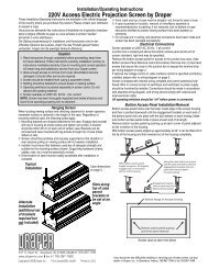
220 V <strong>Revelation</strong> by <strong>Draper</strong> Page 2 of 8<br />
➃ Bottom of unit must be unobstructed after installation. 432mm minimum<br />
clearance is required below the door.<br />
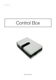
➄ Access should be provided to electrical control box in case service is<br />
required.<br />
➅ Do not use unit to support adjacent light fi xtures, etc.<br />
➆ Do not complete the ceiling below unit until electrical connections have<br />
been completed and unit has been operated successfully.<br />
➇ We recommend that safety cables be attached to the <strong>Revelation</strong> for<br />
added security (a sound in stal la tion practice with overhead equip ment).<br />
Electrical Connections<br />
Unit operates on 220 V a.c., 60 Hz. current.<br />
Opening the access cover on the electrical control box exposes ter mi nals<br />
for field con nec tions. Unit is shipped with internal wiring complete. Wire for<br />
con nect ing unit to switch(es) and to power supply should be fur nished by<br />
elec tri cian. Con nec tions should be made in accordance with wiring diagram<br />
on page 5, and wiring should com ply with national and local elec tri cal codes.<br />
All op er at ing switch es should be “off” before power is connected.<br />
Operation<br />
When unit is fi rst operated, be cautious! If door does not begin to open<br />
momentarily when switch is fl ipped “down”, return switch to “off” and free door<br />
and/or recheck electrical con nec tions before pro ceed ing. Cycle door down<br />
and up several times to confi rm sat is fac to ry operation.<br />
Single Station Control (CE Approved)—Moving 3-position switch to “down”<br />
position will start door down. Moving switch to “up” will start door up. When<br />
door is fully down or fully up, it will au to mat i cal ly be stopped by factory set<br />
limit switch es. When ev er switch is placed in center “off” position, op er a tion will<br />
stop.<br />
Multiple Station Control—Each switching station has a three-button switch<br />
with “up”, “down”, and “off” buttons. Door starts up or down when ap pro pri ate<br />
button is pressed, and may be stopped by pressing “off” button. Factory set<br />
limit switches stop door automatically when door is fully up or fully down.<br />
Key Operated Switch—If ordered, a single station, key-operated three position<br />
(up/off/down) switch is available for this unit.<br />
Video Interface Control (VIC12, VIC12 Modified)—This optional control<br />
device allows the <strong>Revelation</strong> switch to control the operation of a <strong>Draper</strong><br />
mo tor ized pro jec tion screen via relay.<br />
Infrared or Radio Frequency Remote Control (CE Approved)—A three-button<br />
trans mit ter is provided, with “up”, “down”, and “stop” buttons. Door starts<br />
up or down when appropriate button is pressed, and may be stopped by<br />
pressing “off” button. Factory set limit switches stop door automatically when<br />
door is fully up or fully down.<br />
Installing Projector<br />
The <strong>Revelation</strong> has a grounded 220 V a.c., 60Hz outlet for pro jec tor power<br />
sup ply. Power is supplied to this outlet at all times.<br />
Holes are provided for power and control wiring.<br />
Install a projector with the capability to invert its image.<br />
Place the projector into the sliding inner pan so that the center of the projector<br />
lens is aligned L to R with the center of the upper mirror. Position the projector<br />
lens as close as possible to the upper mirror without the refl ected light path<br />
striking any part of the projector. An extension plate is provided if the feet<br />
of your projector rest inside the opening of the inner pan. The extension<br />
is de signed to support the front legs of your projector and the folded up edge<br />
can be used as a stop to help re po si tion the projector when re moved. Adhere<br />
the ex ten sion plate only after you have adjusted the image and marked the<br />
position of the plate.<br />
Establish exact place ment through trial and error using the various ad just -<br />
ments integrated through out the design of the <strong>Revelation</strong>. The upper mirror<br />
can be moved up one inch to ac com mo date taller pro jec tors. Make the neces-<br />
sary connections and plug the power cord of the pro jec tor into the receptacle<br />
provided in the electrical chas sis. Power to the <strong>Revelation</strong> should be turned<br />
off any time electrical connections or mechanical ad just ments are made<br />
to the <strong>Revelation</strong>! Cycle the mir rored door down to the low ered position. You<br />
are now ready to move on to ad just ing the image to the screen.<br />
Adjusting Image<br />
First, use your pro jec tor’s op er at ing manual to establish proper ori en ta tion of<br />
the image and adjust the lens position to achieve the desired image width and<br />
location.<br />
Next, use the <strong>Revelation</strong>'s adjustments to adjust the height of the image on<br />
the screen.<br />
The <strong>Revelation</strong> has two adjustments:<br />
➀ Always start by sliding the inner pan which holds the projector either backward<br />
or forward depending on desired location of image. Sliding the inner<br />
pan towards the projection screen will change where the image strikes the<br />
mirror on the door, and lower the pro ject ed image. Inner pan has a travel<br />
range of ap prox i mate ly 8".<br />
➁ Opening the mirrored door even further into the room will lower the<br />
projected image. The limit switch is factory set to let the door open into<br />
the room at a 45° angle. The door can open approximately 10° farther<br />
by changing the limit switch’s position. You can also tip the front of the<br />
projector up toward the first mirror. This adjustment allows the image to be<br />
projected farther down from the ceiling, but still introduces keystone into<br />
the image. This adjustment offers the same adjustment feature as opening<br />
the mirrored door up farther into the room without adjusting the mirrored<br />
door's limit switches.<br />
Adjust the door only if your projector is equipped with keystone cor rec tion or a<br />
certain amount of keystoning can be tolerated.<br />
To adjust the limit switch of the door:<br />
TOOLS: screwdriver/Allen wrench ( 3 /16"); electronic level or protractor or other<br />
tool to measure angles.<br />
Turn the unit on and open the door to its factory set position. Record the angle<br />
measurement.<br />
Caution: Any adjustments to the limit switches should be done with the<br />
power to the <strong>Revelation</strong> turned off!<br />
Locate the two limit switch brackets at the edge of the top mirror on the motor<br />
side of the pan. The top bracket controls the down ward travel limit of the door<br />
and adjustments are made to this bracket. Note and mark current location of<br />
limit switch bracket. The bottom limit switch bracket is set at the factory for<br />
proper closure alignment and should not need adjusting.<br />
Use a 3 /16" Allen wrench to loosen the two screws on the limit switch bracket<br />
and slide the bracket toward the electrical chassis. A slight adjustment to the<br />
limit switch bracket will result in a significant move ment of the door. It is recommended<br />
that the limit switch be adjusted in small incremental moves of 1 /8".<br />
Tighten the screws. Keeping hands and tools clear of the limit switch, connect<br />
the power. The door should open further. Record the new angle and check the<br />
position of the image on the screen.<br />
If the position of the image on the screen is satisfactory, close the door and<br />
make sure the screws are completely tight.<br />
If the position of the image needs adjusting, leave the door open, dis con nect<br />
the power, loosen the screws and slide the bracket toward the motor to open<br />
the door more, or slide the bracket closer to its original position.<br />
Check alignment of image and repeat adjustment procedure as nec es -<br />
sary. After all adjustments are completed, be sure to tighten all loos ened<br />
screws to inner pan and limit switch bracket!<br />
Please Note<br />
If Glass Shield is provided, see separate in struc tions (provided<br />
with Glass Shield).<br />
www.draperinc.com (765) 987-7999