Mount Instructions Revelation - Draper Group Ltd
Mount Instructions Revelation - Draper Group Ltd
Mount Instructions Revelation - Draper Group Ltd

You also want an ePaper? Increase the reach of your titles
YUMPU automatically turns print PDFs into web optimized ePapers that Google loves.
I<br />
I<br />
t<br />
I<br />
1<br />
2<br />
6<br />
9<br />
4<br />
3<br />
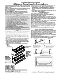
220 V <strong>Revelation</strong> by <strong>Draper</strong> Page 6 of 8<br />
Field Installation of Environmental Airspace Housing Kit<br />
Caution! Disconnect power from the <strong>Revelation</strong> before installing Environmental<br />
Airspace Housing.<br />
➀ Remove the covers from the electrical chassis in the <strong>Revelation</strong>.<br />
➁ Disconnect the black 14 awg. wire that runs from the T2 trans form er to<br />
the re cep ta cle in the electrical chassis.<br />
➂ Install the pre-wired current sensor using two #6-32 x 1" [10] long screws<br />
provided. (SEE FIGURE #1.)<br />
➃ Connect each wire of the pre-wired current sensor as shown by DIA-<br />
GRAM #1.<br />
➄ Install the two fan mount assemblies [5,6] to the main pan of the Rev e -<br />
la tion using the eight #10-32 x . 3 /8" [7,8] long screws provided. (SEE<br />
FIGURE #1.) Attach the long leads of the Exhaust Fan As sem bly [6] to<br />
the end with the motor and lifting mechanism.<br />
➅ Using the wire clips [11] provided, lay in the wires from the fans as<br />
shown in FIG URE #1 and con nect the fans to TB1-8 & TB1-9 as shown<br />
in DI A GRAM #1.<br />
➆ Replace the covers to the electrical chassis.<br />
➇ Apply the 25 mm wide Nylon [12,13] tape as shown in FIGURE #1.<br />
➈ Install the inner and outer plenum covers [1,2], and attach the mating<br />
end panel [3,4] as shown in FIGURE #2.<br />
➉ Fan mounting panels are designed to accept a standard 4" round duct.<br />
The exhaust fl ange is located on the motor/drive end of the Rev e la tion<br />
and the input is located at projector end of the <strong>Revelation</strong>.<br />
If duct work is connected to this unit, here are a few recommended guide lines<br />
you should keep in mind when installing the duct work:<br />
• Air supply to the Environmental Airspace Housing should be cool enough<br />
to provide adequate cooling for your projector.<br />
• Do not obstruct airfl ow through duct work. Inadequate airfl ow may result in<br />
excessive heat buildup inside the unit.<br />
• Keep duct work length as short as possible. Recommended maximum total<br />
duct length is 914 cm (input plus ex haust).<br />
• Keep the input-to-exhaust length ratio balanced and as small as possible<br />
to prevent air from being pushed into or drawn out of the room.<br />
FIGURE #1<br />
TB1<br />
Nylon tape 43" long<br />
Input<br />
fan<br />
assembly<br />
(short<br />
wires)<br />
Wire clips typ.<br />
FIGURE #2<br />
Exhaust<br />
fan<br />
assembly<br />
Outer end panel<br />
TB1 T2 F4<br />
F5<br />
1 12<br />
Projector<br />
Outer Environmental<br />
Air Space Housing<br />
cover<br />
BK<br />
BK WH BK RD<br />
1 2 3 4 5<br />
CS1<br />
T2 transformer<br />
CB1B<br />
1 10<br />
T1<br />
F3<br />
PCB1<br />
F2<br />
F1<br />
1 10<br />
CB1A<br />
Curent sensor<br />
F1 = 7 Ampere<br />
F2 = 1 Ampere<br />
F3 = 1 Ampere<br />
F4 = 4 Ampere<br />
F5 = 4 Ampere<br />
Inner Environmental<br />
Air Space Housing<br />
cover<br />
CR1<br />
CR2<br />
C1<br />
PCB1<br />
TB2<br />
1 12<br />
Motor<br />
Nylon tape 39" long<br />
Exhaust<br />
fan<br />
assembly<br />
(long<br />
wires)<br />
Inner end panel<br />
Input<br />
fan<br />
assembly<br />
DIAGRAM #1<br />
FAN<br />
(IN)<br />
FAN<br />
(OUT)<br />
220 VAC SUPPLY N<br />
50 - 60 HZ<br />
L1<br />
NOTES:<br />
1.<br />
2.<br />
BK<br />
PROJECTOR<br />
OUTLET<br />
BK<br />
1 2 3 4 5 6 7 8 9 10 11 12<br />
RD<br />
TB 1<br />
BE<br />
14 AWG<br />
14 AWG<br />
YW/GN<br />
14 AWG<br />
YW/GN<br />
RD<br />
WIRE TO BE REMOVED BEFORE INSTALLING PLENUM WIRING<br />
WIRES CONNECTED BY INSTALLER<br />
4 TURNS<br />
14 AWG<br />
3. ALL WIRES 18 AWG. UNLESS OTHERWISE SPECIFIED.<br />
RD<br />
BE<br />
BE<br />
C2<br />
D1<br />
BE<br />
WH<br />
CS 1<br />
1 2<br />
BK<br />
BK<br />
BK<br />
BK<br />
RD<br />
BK<br />
3 4 5<br />
3 4 5<br />
7 8<br />
10<br />
CB1B<br />
F3<br />
PCB 1<br />
F2<br />
F1<br />
5 2 1<br />
10 9 8 7 6<br />
CB1A<br />
BE<br />
BE<br />
BE<br />
BK<br />
ENVIRONMENTAL AIRSPACE HOUSING<br />
INSTALLATION PART LIST<br />
ITEM# DESCRIPTION<br />
QTY<br />
1 INNER ENVIRONMENTAL AIRSPACE HOUSING COVER 1<br />
2 OUTER ENVIRONMENTAL AIRSPACE HOUSING COVER 1<br />
3 INNER END PANEL 1<br />
4 OUTER END PANEL 1<br />
5 INPUT FAN MOUNT ASSEMBLY 1<br />
6 EXHAUST FAN MOUNT ASSEMBLY 1<br />
7 SCREW #10–32 X .375" (9.525mm) 8<br />
HEX HD TYPE "F" ZINC<br />
8 WASHER, #10 ZINC INTERNAL LOCK 8<br />
9 PRE-WIRED CURRENT SENSOR 1<br />
10 SCREW #6–32 X 1" (25.4mm) 2<br />
LONG PHIL PAN HD ZINC<br />
11 CLIP ADHESIVE BACKED CORD 7<br />
6.35mm HOLD ING DIA.<br />
12 991 mm LONG 25.4mm WIDE X .762mm 1<br />
THICK NYLON TAPE<br />
13 1092mm LONG 25.4mm WIDE X .762mm 1<br />
THICK NYLON TAPE<br />
TOOLS NEEDED<br />
MED POINT PHILLIP SCREWDRIVER<br />
1<br />
/8" FLAT BLADE SCREW DRIVER<br />
3<br />
/8" WRENCH<br />
www.draperinc.com (765) 987-7999