
You also want an ePaper? Increase the reach of your titles
YUMPU automatically turns print PDFs into web optimized ePapers that Google loves.
83 Carbon Metallic Highway • Clover, SC • 29710 • Tel: 803-222-2141 • Fax: 803-222-8134<br />
www.performancefriction.com<br />
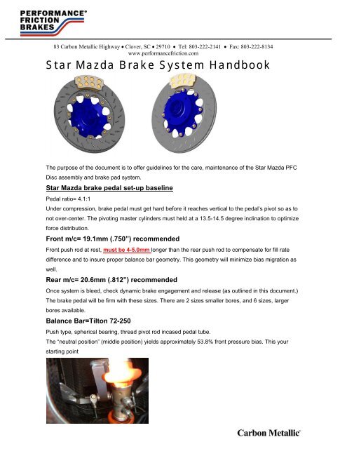
<strong>Star</strong> <strong>Mazda</strong> <strong>Brake</strong> System Handbook<br />
Subject:<br />
The purpose of the document is to offer guidelines for the care, maintenance of the <strong>Star</strong> <strong>Mazda</strong> <strong>PFC</strong><br />
Disc assembly and brake pad system.<br />
<strong>Star</strong> <strong>Mazda</strong> brake pedal set-up baseline<br />
Pedal ratio= 4.1:1<br />
Under compression, brake pedal must get hard before it reaches vertical to the pedal’s pivot so as to<br />
not over-center. The pivoting master cylinders must held at a 13.5-14.5 degree inclination to optimize<br />
force distribution.<br />
Front m/c= 19.1mm (.750”) recommended<br />
Front push rod at rest, must be 4-5.0mm longer than the rear push rod to compensate for fill rate<br />
difference and to insure proper balance bar geometry. This geometry will minimize bias migration as<br />
well.<br />
Rear m/c= 20.6mm (.812”) recommended<br />
Once system is bleed, check dynamic brake engagement and release (as outlined in this document.)<br />
The brake pedal will be firm with these sizes. There are 2 sizes smaller bores, and 6 sizes, larger<br />
bores available.<br />
Balance Bar=Tilton 72-250<br />
Push type, spherical bearing, thread pivot rod incased pedal tube.<br />
The “neutral position” (middle position) yields approximately 53.8% front pressure bias. This your<br />
starting point
83 Carbon Metallic Highway • Clover, SC • 29710 • Tel: 803-222-2141 • Fax: 803-222-8134<br />
www.performancefriction.com<br />
Balance bar set-up and technical notes<br />
Purpose:<br />
The function of a balance bar is to allow the adjustment of brake line pressure distribution between<br />
two master cylinders. This is accomplished through moving the balance bar pivot towards one<br />
master cylinder or the other. If the pivot is perfectly centered between the pushrods, the force applied<br />
to each master cylinder will be equal. This is known as the “neutral position” of the bias adjuster. If<br />
the pivot is moved closer to one master cylinder or the other, then the master cylinders will receive<br />
differential forces that are inversely proportional to the distance between the balance bar pivot point<br />
and master cylinder center lines. Being able to move the pivot point allows the driver to make<br />
incremental adjustments to the braking characteristics of the car (front-to-rear brake bias) and to alter<br />
those characteristics to account for changes in fuel load, track conditions and handling of the car.<br />
Pedal Assembly Types<br />
There are 2 types of brake pedal assemblies in common usage today. The traditional type, and by far<br />
the most common, is the “push-type” or “compression” pedal assembly. In this type of pedal, the<br />
brake master cylinder pushrods are actuated and push the piston into the body of the master cylinder.<br />
The pressure outlet is mounted on the opposite end of the master cylinder body from the pushrod.<br />
The second option, which is become more prevalent recently, is the “pull-type” or “tension” pedal<br />
assembly. In this type of pedal assembly, the master cylinder piston is pulled through the master<br />
cylinder body by the master cylinder pull rod. To accomplish this, the piston pull rod assembly is 1-<br />
piece. The pressure outlet for the master cylinder is located on the pull rod side of the piston in the<br />
master cylinder body. This type of pedal assembly is typically found in high-end racecars such as F1,<br />
but has gained favor in all types of racing due to much reduced hysterisis.<br />
Setting Up the <strong>Brake</strong> Balance Bar: Push Type<br />
The brake balance bar is one of the most overlooked, and least<br />
understood, components on a racecar. As with all aspects of racecar<br />
assembly and preparation, careful attention to the geometry of the<br />
brake balance bar and brake pedal will yield great benefits. To start<br />
with, look for proper installation of the brake balance bar bias<br />
adjuster and ensure that the brake balance bar pivot bearing is free<br />
to move within the threaded trunion. There are important installation<br />
and maintenance considerations for the push type pedal assembly.<br />
The articulating push type pedal assembly (wherein the master<br />
cylinder is mounted through a spherical joint), there are numerous spherical bearings, rod ends,<br />
clevises and needle bearings in these systems. These components must be in proper working order<br />
and clean of debris and dirt to function properly. Any excess play in these components will adversely<br />
affect the control and release of the brake system, and should be avoided at all costs.
83 Carbon Metallic Highway • Clover, SC • 29710 • Tel: 803-222-2141 • Fax: 803-222-8134<br />
www.performancefriction.com<br />
Next, find the distance between the centerlines of the front and rear master cylinders. Typically, this<br />
could be 2½ inches, but is not critical. What’s critical is that this measurement, whatever it is, is<br />
exactly duplicated in the center-to-center distance of the clevises threaded onto the bias adjuster.<br />
This ensures that the master cylinder pushrods are actuated properly, minimizing any side loads<br />
applied to the master cylinder piston and bore. With the clevises set on the bias adjuster, measure<br />
the distance between each clevis<br />
and the balance bar. This will prevent the balance bar from shifting<br />
while on the track and causing unpredictable change in the brake<br />
bias of the car. With the balance bar connected to the master<br />
cylinders, and brake lines connected, the brakes should be bled. It is<br />
critical that front and rear brake circuits be bled simultaneously so<br />
that both master cylinders are allowed to use their full travel, and<br />
prevent binding or distortion of the bias adjuster.<br />
Once satisfied that the clevises and pedal tube clearances have been<br />
properly set, now look at master cylinder pushrod length. The key is<br />
to set the bias adjuster so that it is perpendicular to the master<br />
cylinder centerlines when the brake pedal is under pressure.<br />
Typically, this means that the front master cylinder pushrod will be 4mm-5mm (.160-.200”) longer<br />
than the rear master cylinder pushrod when at rest. This is due to the front braking circuit having<br />
either larger fluid volume needed to feed the larger piston diameters of the front calipers or a smaller<br />
front master cylinder to augment the higher pressure requirements. As a result the front master<br />
cylinder requires a higher feed rate than does the rear. If the pushrod lengths are equal then the feed<br />
rate of the rear master cylinder is too high relative to the front and that would result in the rear circuit<br />
“hitting” before the front. So, with the pushrod lengths adjusted properly, the balance bar will be<br />
square with the pedal frame under compression, with the front and rear circuits engaging and<br />
releasing at the same moment.<br />
<strong>Brake</strong> Pedal Geometry<br />
With the balance bar geometry now correct, it is now time to the brake pedal geometry. In order for<br />
the brake system to work properly, it is important that the brake pedal get hard before it crosses the<br />
vertical plane of the brake pedal pivot. If the brake pedal crosses the vertical plane of the pedal pivot<br />
(goes “over center”) then the mechanical advantage of the pedal, over the pushrods, will be lost.<br />
That would result in a loss of pedal feel and braking force efficiency. Adjust the pedal “over center”<br />
position with a separate pedal height adjuster, if available, or by lengthening both master cylinder<br />
pushrods by the same amount and until the desired pedal height is achieved. When tall drivers are<br />
being fitted, this may require that pedal pivot be moved forward or the brake pedal cluster to be<br />
moved forward. As a result, the throttle pedal may need to be adjusted to restore the proper heel-and-
83 Carbon Metallic Highway • Clover, SC • 29710 • Tel: 803-222-2141 • Fax: 803-222-8134<br />
www.performancefriction.com<br />
toe pedal relationship. If there is insufficient adjustment available then this can be accomplished by<br />
attaching a simple spacer to the throttle pedal.<br />
<strong>Star</strong> <strong>Mazda</strong> <strong>Brake</strong> Bias<br />
For the <strong>Star</strong> Racecars, 55/45% is a good starting point, checked at the master cylinders.<br />
<strong>Brake</strong> system bleeding procedures<br />
Purpose:<br />
Proper bleeding of the brake system is critical to the performance of any racecar. Without good<br />
quality, clean, fresh brake fluid and a properly bled brake system, the brake system cannot function<br />
properly. There are many misconceptions about bleeding brakes and brake fluid in general. The<br />
purpose of this article is to help dispel some of these myths and outline a reliable and repeatable<br />
method for bleeding the brake system.<br />
<strong>Brake</strong> Fluid 101<br />
There are 2 types of brake fluids commonly available today. Glycol-ester blends (“glycol-based”) and<br />
high percentage ester content blends (“ester-based”). More common are the glycol-based. These<br />
glycol-based fluids normally have low compressibility but are “hygroscopic” in nature. This means<br />
they are able to absorb water from the atmosphere. This contamination process occurs whenever<br />
brake fluids are exposed to the atmosphere, and even occurs somewhat through the plastic bottles<br />
most brake fluids are packaged in. This is the reason that all brake fluids must be used fresh. The<br />
susceptibility of brake fluids to hygroscopic contamination can be judged by comparing the “dry<br />
boiling point” and “wet boiling point” of the fluid: the greater the difference is between these two<br />
ratings, the more hygroscopic is the nature of that fluid. This concept is important, as it is the<br />
absorbed water that gasses off (boils) first inside the brake system and adds to the “spongy/soft/long<br />
pedal” effect. Pay no attention to the large numbers used by the marketers to describe the product, as<br />
they can be very misleading. The dry boiling point of glycol-based brake fluids seldom exceeds 580F<br />
(304c), even though you’ll see 600, 610 and 660 as a label description. The use of <strong>PFC</strong> caliper<br />
temperature stickers, PN 032.0007 is highly recommended to monitor brake fluid and caliper seal<br />
condition. If the calipers exceed 430f (210c) for an extend period, the brake fluid and or caliper seals<br />
will deteriorate. High percentage ester blends have the promise of higher dry and wet boiling points.<br />
The ester base used in manufacturing these fluids is not hygroscopic at all. However, they are<br />
blended with a percentage of glycol for several reasons including cost (ester is more expensive to<br />
manufacture than glycol), pedal feel (ester is by nature more compressible than glycol), lubricity and<br />
seal conditioning. The most common ester-based brake fluid on the market, and the established<br />
standard in the racing industry, is Castrol SRF. It has a proprietary formulation and effectively<br />
combines the best properties of the ester base (stability at elevated temperatures and low<br />
hygroscopic characteristics) with compressibility near that of glycol-based fluids. <strong>PFC</strong> recommends<br />
Castrol SRF racing brake fluid because of decades of proven consistency and performance.
83 Carbon Metallic Highway • Clover, SC • 29710 • Tel: 803-222-2141 • Fax: 803-222-8134<br />
www.performancefriction.com<br />
However, not all high ester blends are equal. In many cases, although they may have less water<br />
content to boil, compressibility is not as good at elevated temperatures, and the soft/spongy/long<br />
pedal effect is the same. Regardless of which brake fluid is used, frequent and correct bleeding<br />
should be considered part of proper race preparation.<br />
<strong>Brake</strong> Bleeding How To<br />
As with any system on a racecar, the brake system must be inspected and found to be in good<br />
working order before beginning. Inspect the entire brake system for leaks or damaged parts including<br />
the pedal assembly (refer to the Balance Bar setup guide). Inspect the master cylinder reservoir<br />
cap(s) to see that they are venting properly, as this is an overlooked and common cause for poor<br />
pedal feel. Once all of the components in the system have been inspected and serviced as<br />
necessary, begin the bleeding process by filling the master cylinder reservoir with clean, fresh, high<br />
quality brake fluid. Depending on the type of master cylinder arrangement, follow the instructions<br />
below:<br />
Notes on Bleed Bottles:<br />
There are many brake bleed bottles commercially available for a reasonable price. It is helpful for the<br />
bleed bottle to be clear so a visual inspection of the fluid being purged is possible. The use of clear<br />
hose that fits tightly around the bleed screws adds a visual aid to bleeding then just relying on what is<br />
seen through the bleeder bottle. For the calipers, this hose should have a 6.0mm (.250”) ID to fit the<br />
bleed screws properly. Insure that the bleed hose is inserted deeply enough into the bottle so that<br />
the end is submerged in brake fluid to help close the loop. Bleed bottles should be vented as well.<br />
Discard spent brake fluid in an approved manor.<br />
Notes on Master Cylinder Fluid Reservoirs<br />
The master cylinder fluid level must be higher than the calipers bleed screws to insure proper<br />
bleeding. This means that the floor-mounted pedal used, the fluid reservoirs should be remote<br />
mounted above the level of the caliper bleed screws. You should take into consideration dynamic<br />
wheel movement as well, so placement of the reservoir is important. The fluid volume required for a<br />
master cylinder reservoir is based upon the maximum piston displacement of the calipers being used.<br />
In this case, maximum fluid volume required is 60cc per circuit. If there is insufficient fluid volume in<br />
the reservoir for the piston displacement required, the master cylinder will be empty before the pads<br />
are worn to their maximum. Total brake failure will result.
83 Carbon Metallic Highway • Clover, SC • 29710 • Tel: 803-222-2141 • Fax: 803-222-8134<br />
www.performancefriction.com<br />
Vehicle with Dual Master Cylinder and Racing Calipers<br />
Supplies needed:<br />
- 3 people<br />
- Supply of high quality brake fluid from an unopened container<br />
- 2 brake bleed bottles<br />
- 2 6 point box end or line wrenches for bleed screws on calipers<br />
Important Notes<br />
It is imperative that both ends of the car be bled simultaneously when using dual master cylinders. If<br />
this is not done, the master cylinders will not be adequately purged of contaminated brake fluid.<br />
Further, the balance bar assembly may be severely damaged, leading to a failure of the brake<br />
system.<br />
With the car on jack stands and a person sitting in the drivers seat:<br />
1. Place a wrench over the inboard bleed screw on one front and one rear caliper.<br />
2. Place the bleed hose attached to the bleed bottle over the bleed nipple with the wrenches.<br />
3. Open the bleed screws.<br />
4. With the bleed screw is open, have the “driver” slowly depress the brake pedal to the floor.<br />
With the driver holding the pedal down, gently close the bleed screws. With the bleeder<br />
closed, the driver can release the brake pedal.<br />
5. Repeat this process until the fluid coming from the calipers is clear and free of all air bubbles.<br />
6. Repeat this process for the outboard bleeders.<br />
7. Monitor the fluid level in the reservoirs and refill as necessary during the process.<br />
When finished torque bleeders to factory recommended settings Torque <strong>PFC</strong> bleed screws 48-60 inlbs.<br />
Repeat these steps for the remaining calipers, bleeding the front and rear circuits simultaneously.<br />
At times it is helpful to tap the caliper body with a soft mallet to release any small air bubbles trapped<br />
inside the caliper. At this point, the brake pedal should be checked for firmness and consistency. If<br />
the fluid is free of air bubbles and the pedal is still soft or spongy, there may be further issues that<br />
need to be addressed with the brake system. When finished, fill the fluid reservoir to the “full” line,<br />
but not over.<br />
Alternate Bleeding Methods<br />
The methods outlined above are not intended to be the sole methods approved for bleeding brake<br />
systems. However, they are reliable and repeatable techniques designed to minimize the cavitations<br />
that occurs when fluids move too rapidly through small passages and orifices. Bleeding brakes is not<br />
a pressure dependent process; it is a flow dependent process. All that is required is the slow and<br />
steady evacuation of contaminated fluid and air from the system.<br />
Power <strong>Brake</strong> Bleeders<br />
Power brake bleeders operate through applying external pressure to the brake fluid reservoir<br />
(pressure bleeders). If a power bleeder system is used, be sure a bellows or rubber diaphragm is<br />
used where the power bleeder applies its pressure to the reservoir area. This reduces water or other<br />
contaminants from affecting the brake fluid. Vacuum Bleeders apply a vacuum to the bleed screw at<br />
the calipers and draw the fluid out the system. These are typically used in car repair shops and are<br />
not generally considered acceptable for racing applications.
83 Carbon Metallic Highway • Clover, SC • 29710 • Tel: 803-222-2141 • Fax: 803-222-8134<br />
www.performancefriction.com<br />
Closed Loop System Bleeding<br />
Closed loop systems circulate the brake fluid from the calipers back to front of the master cylinders<br />
via a series of check valves when the brake pedal is depressed and released and displace a the<br />
small amount of fluid from brake wear. These types of systems add a tremendous amount of brake<br />
drag as well as poor release characteristics. <strong>PFC</strong> strongly discourages the use of these systems.<br />
This does not obviate the need to bleed the brakes, as the brake fluid becomes contaminated, just as<br />
in a conventional brake system. If a closed loop system is used, then 100% of the old fluid must be<br />
removed before bleeding these types of systems. If the fluid is not replaced frequently, the entire<br />
system will become contaminated and failure will result.<br />
<strong>Brake</strong> Fluid Disposal<br />
All brake fluids must be disposed of properly. Their ability to combine with water means they can<br />
very easily contaminate ground water supplies if disposed of improperly.<br />
Bleed screw Assembly<br />
Bleed screw torque is 48-60 in-lbs. This should be checked often, as there are no separate bleeder<br />
screw seats. This means there are two dissimilar materials with steel bleed screw and a cast<br />
aluminum caliper body. Two dissimilar materials will have differential growth at elevated temperatures<br />
and may affect torque integrity. .<br />
<strong>PFC</strong> component part numbers specific for <strong>Star</strong> Racecars<br />
<strong>PFC</strong> Part Number*<br />
Description<br />
278.18.0041.51 LH <strong>PFC</strong> 48v disc-includes hardware<br />
278.18.0041.52 RH <strong>PFC</strong> 48v disc-includes hardware<br />
900.700.113.07 Peg-Drive bobbin kit<br />
7745.01.16.54 <strong>PFC</strong> 01 pads for <strong>Star</strong> Racecars<br />
7745.05.16.54 <strong>PFC</strong> 05 pads for <strong>Star</strong> Racecars<br />
*Available through <strong>Star</strong> Racecars only
83 Carbon Metallic Highway • Clover, SC • 29710 • Tel: 803-222-2141 • Fax: 803-222-8134<br />
www.performancefriction.com<br />
<strong>Star</strong> <strong>Mazda</strong> Performance Friction Corp. Inc. Disc Installation Instructions<br />
Disc<br />
Wheel Mounting<br />
Surface<br />
Aluminum Hub /<br />
Rotor Hat<br />
Bobbin<br />
Nut<br />
Washer<br />
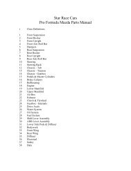
<strong>Star</strong> <strong>Mazda</strong> Floating Disc Assembly Steps:<br />
1. Place disc onto hub / rotor hat and align flanges of the disc with the bolt pattern of the hat<br />
2. <strong>PFC</strong> recommends a small dab of nickel anti-seize on the peg-drives. Place peg-drive through the<br />
disc flange window and install the washers and nuts as show in the diagram below. The order you<br />
install the bobbins DOES NOT matter.<br />
3. With all nuts hand tight, torque each nut to the recommended torque of 80in.lbs (9Nm) in a star like<br />
pattern.<br />
4. Once all the hardware is tightened, you can now square the <strong>PFC</strong> peg-drive to the slot windows by<br />
using an Allen wrench on the broached socket head of the <strong>PFC</strong> peg-drive.<br />
5. Check for float by tapping the discs with a soft blow hammer and listen for the “rattle”.<br />
6. New <strong>PFC</strong> discs will burnish with new or used pads. <strong>PFC</strong> discs are heat-treated and stress relieved.
83 Carbon Metallic Highway • Clover, SC • 29710 • Tel: 803-222-2141 • Fax: 803-222-8134<br />
www.performancefriction.com<br />
<strong>PFC</strong> <strong>Brake</strong> Pad Notes<br />
7745.01.01.54 pads are the baseline compound pads. 01 compound has won in virtually ALL automobileracing<br />
venues and is a favorite for low grip conditions such as street races. Recommended for left-foot<br />
brakers. Excellent initial bite, flat torque curve, excellent control and release. Very long wearing, very little<br />
pad taper with proper force distribution<br />
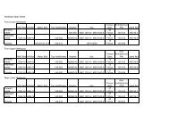
<strong>Star</strong> <strong>Mazda</strong> Formula Car<br />
VEHICLE DATA<br />
H-type calipers w31.8mm pistons<br />
PEDAL RATIO 4.00 19.1mm(.750") front/20.6mm(.812") rear master cylinders<br />
APPLIED PEDAL FORCE (lbs) 155.00<br />
LINE PRESSURE FRONT (psi) 698.03 50.0% F Bias Balance bar 50%, PSI bias 53.8%Front<br />
LINE PRESSURE REAR (psi) 600.07 50.0% R Bias<br />
FRONT<br />
SIZE (mm)<br />
AREA(mm^2)<br />
FRONT MASTER CYLINDER 19.1 286.5 REAR MASTER CYLINDER 20.6 333.3<br />
CALIPER PISTON SIZES 1 31.8 794.2 CALIPER PISTON SIZES 1 31.8 794.2<br />
2 31.8 794.2 2 31.8 794.2<br />
3 0.0 3 0.0<br />
4 4<br />
1.16 5.5 4.8<br />
TOTAL CALIPER PISTON AREA (in^2) 4.94 TOTAL CALIPER PISTON AREA(in^2) 4.94<br />
FRONT CLAMP FORCE (lb) 6898.46 REAR CLAMP FORCE (lb) 5927.51<br />
DISC DIAMETER (mm) 278.00 DISC DIAMETER (mm) 278.00<br />
PAD RADIAL DEPTH (mm) 42.00 PAD RADIAL DEPTH (mm) 42.00<br />
EFFECTIVE RADIUS (mm) 118.00 EFFECTIVE RADIUS (mm) 118.00<br />
BRAKE FACTOR (in^3) 206.76 BRAKE FACTOR (in^3) 177.66<br />
MU VALUE 0.45 MU VALUE 0.45<br />
ESTIMATED BRAKE TORQUE (ft-lb) 1201.80 ESTIMATED BRAKE TORQUE(ft-lb) 1032.65<br />
FRONT BRAKING % 53.8 REAR BRAKING % 46.2<br />
TOTAL BRAKE FACTOR 384.42<br />
TOTAL BRAKE TORQUE (ft-lb)<br />
2234.45<br />
REQIURED DATA INPUTS 0.49268<br />
REAR<br />
SIZE (mm)<br />
AREA(mm^2)
83 Carbon Metallic Highway • Clover, SC • 29710 • Tel: 803-222-2141 • Fax: 803-222-8134<br />
www.performancefriction.com<br />
7845.05.16.44 brake pad set is <strong>PFC</strong>’s high bite, high torque compound. It has 32% more average bite<br />
and torque than <strong>PFC</strong> 01 compound and when hot, will have excellent release and modulation.<br />
05 pads are recommended for right foot brakers, high down force, higher grip tracks. If rear control is<br />
an issue on bumpy track conditions but the drivers still wants the higher bite, using 05 front pads, 01<br />
rear pads maybe a solution.<br />
<strong>Star</strong> <strong>Mazda</strong> Formula Car<br />
VEHICLE DATA<br />
H-type calipers w31.8mm pistons<br />
PEDAL RATIO 4.00 19.1mm(.750") front/20.6mm(.812") rear master cylinders<br />
APPLIED PEDAL FORCE (lbs) 155.00<br />
LINE PRESSURE FRONT (psi) 698.03 50.0% F Bias Balance bar 50%, PSI bias 53.8%<br />
LINE PRESSURE REAR (psi) 600.07 50.0% R Bias<br />
FRONT<br />
SIZE (mm)<br />
AREA(mm^2)<br />
FRONT MASTER CYLINDER 19.1 286.5 REAR MASTER CYLINDER 20.6 333.3<br />
CALIPER PISTON SIZES 1 31.8 794.2 CALIPER PISTON SIZES 1 31.8 794.2<br />
2 31.8 794.2 2 31.8 794.2<br />
3 0.0 3 0.0<br />
4 4<br />
1.16 5.5 4.8<br />
TOTAL CALIPER PISTON AREA (in^2) 4.94 TOTAL CALIPER PISTON AREA(in^2) 4.94<br />
FRONT CLAMP FORCE (lb) 6898.46 REAR CLAMP FORCE (lb) 5927.51<br />
DISC DIAMETER (mm) 278.00 DISC DIAMETER (mm) 278.00<br />
PAD RADIAL DEPTH (mm) 42.00 PAD RADIAL DEPTH (mm) 42.00<br />
EFFECTIVE RADIUS (mm) 118.00 EFFECTIVE RADIUS (mm) 118.00<br />
BRAKE FACTOR (in^3) 206.76 BRAKE FACTOR (in^3) 177.66<br />
MU VALUE 0.67 MU VALUE 0.67<br />
ESTIMATED BRAKE TORQUE (ft-lb) 1789.35 ESTIMATED BRAKE TORQUE(ft-lb) 1537.50<br />
FRONT BRAKING % 53.8 REAR BRAKING % 46.2<br />
TOTAL BRAKE FACTOR 384.42<br />
TOTAL BRAKE TORQUE (ft-lb)<br />
3326.84<br />
REQIURED DATA INPUTS 0.49268<br />
REAR<br />
SIZE (mm)<br />
AREA(mm^2)<br />
Bedding New <strong>PFC</strong> Pads<br />
If the <strong>PFC</strong> discs are already used and are in good condition bedding new <strong>PFC</strong> pads will be a very<br />
simple procedure. <strong>Brake</strong> cooling ducts should be open and fully functional, perform the following<br />
procedures. On the out lap, perform a dozen brake snubs with progressively higher pedal pressure<br />
and braking force from slow to higher speeds. You will feel the effectiveness of the brakes increase<br />
with each successive snub. First the fronts will come in then the rears. This should take six to ten<br />
brake snubs and is typically completed in one or two laps. As soon as the brakes become more<br />
responsive the car can be driven normally and at increased speeds. Be sure to check your mirrors for<br />
any on coming cars. Running the car at speed for one or two more laps will allow the disc to achieve<br />
the desired core temperature. If three-color rotor paints are used, the green paint should be fully
83 Carbon Metallic Highway • Clover, SC • 29710 • Tel: 803-222-2141 • Fax: 803-222-8134<br />
www.performancefriction.com<br />
oxidized and the orange paint beginning to oxidize to white. A transfer layer of pad material will<br />
deposit on the disc; this transfer layer is from a slate-gray to a highly polished coloration on the disc<br />
friction surface. This is a good indication that the disc and pads have been bedded properly.<br />
<strong>PFC</strong> disc conditioning<br />
Thermal fatigue of iron discs is a common wear factor. Ideal disc temperatures is were the disc’s<br />
cheeks and its core is about 500c (900f). Using temperature sensitive paints is highly recommended.<br />
<strong>PFC</strong> recommends the 50-100% of the orange paint be oxidized from the brake disc cheeks through<br />
the disc’s cores. This will reduce temperature variation and help minimize disc face fatigue. When the<br />
disc face has tension cracks in excess of 6-8.0mm long, the discs are done and it’s time to replace.<br />
The <strong>PFC</strong> discs incorporate a patented slot pattern. The unique slot pattern aids to removal pad<br />
material debris without disrupting the pad’s interface with the disc’s surface for increased bite. It is not<br />
unusual to see a “rippled” look to disc’s transfer layer from the <strong>PFC</strong> pads. This rippling is simply the<br />
debris path of the friction material. It has little or no effect to the braking performance. The 01 pad<br />
transfer has a “grey slate” color to it, the 05 has more of a “polished” look to it. Both feature a fine<br />
micronic conditioning of the disc’s surface.<br />
Bedding New Performance Friction <strong>Brake</strong> Discs<br />
Ensure that the brake discs are clean and free of grease or other contaminants. Once the<br />
discs and pads are installed perform the following procedure with brake cooling ducts fully open<br />
and functional—no tape! Best results are achieved using new Performance Friction brake<br />
pads. It is not necessary to bed in new <strong>PFC</strong> discs with used <strong>PFC</strong> pads.<br />
On the out lap, perform a dozen brake snubs with progressively higher pedal pressure and braking<br />
force from slow to higher speeds. You will feel the effectiveness of the brakes increase with each<br />
successive snub. First the fronts will come in then the rears. This should take six to ten brake snubs<br />
and is typically completed in one or two laps. As soon as the brakes become more responsive the<br />
car can be driven normally and at increased speeds. Be sure to check your mirrors for any on<br />
coming cars.<br />
Running the car at speed for one or two more laps will allow the disc to achieve the desired core<br />
temperature. If three-color rotor paints are used, the green paint should be fully oxidized and the<br />
orange paint beginning to oxidize to white. A transfer layer of pad material will deposit on the disc;<br />
this transfer layer is from a slate-gray to a highly polished coloration on the disc friction surface. This<br />
is a good indication that the disc and pads have been bedded properly.<br />
Note: Sanding/machine grinding the discs will not decrease the bedding time. Whenever new<br />
Performance Friction pads are installed, the pads require very little cool down time. Usually the time<br />
spent taking tire temperatures and a debriefing with the driver is sufficient.