Lesson 5 Fabric Filter Design Review
Lesson 5 Fabric Filter Design Review
Lesson 5 Fabric Filter Design Review

Create successful ePaper yourself
Turn your PDF publications into a flip-book with our unique Google optimized e-Paper software.
<strong>Lesson</strong> 5<br />
<strong>Fabric</strong> <strong>Filter</strong> <strong>Design</strong> <strong>Review</strong><br />
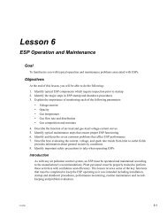
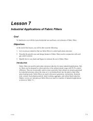
Goal<br />
To familiarize you with the factors to be considered when reviewing baghouse design plans for air<br />
pollution control programs.<br />
Objectives<br />
At the end of this lesson, you will be able to do the following:<br />
1. List and explain at least six factors important in good baghouse design<br />
2. Estimate the cloth area needed for a given gas process flow rate<br />
3. Calculate the number of bags required in a baghouse for a given process flow rate<br />
4. Calculate the gross air-to-cloth ratio, the net air-to-cloth ratio, and the net,net air-to-cloth ratio<br />
for a baghouse design<br />
Introduction<br />
The design of an industrial baghouse involves consideration of many factors including space<br />
restriction, cleaning method, fabric construction, fiber, air-to-cloth ratio; and many construction<br />
details such as inlet location, hopper design, and dust discharge devices. Air pollution<br />
control agency personnel who review baghouse design plans should consider these factors<br />
during the review process.<br />
A given process might often dictate a specified type of baghouse for particulate emission control.<br />
The manufacturer’s previous experience with a particular industry is sometimes the key<br />
factor. For example, a pulse-jet baghouse with its higher filter rates would take up less space<br />
and would be easier to maintain than a shaker or reverse-air baghouse. But if the baghouse was<br />
to be used in a high temperature application (500°F or 260°C), a reverse-air cleaning baghouse<br />
with woven fiberglass bags might be chosen. This would prevent the need of exhaust gas cooling<br />
for the use of Nomex felt bags (on the pulse-jet unit), which are more expensive than fiberglass<br />
bags. All design factors must be weighed carefully in choosing the most appropriate<br />
baghouse design.<br />
<strong>Review</strong> of <strong>Design</strong> Criteria<br />
The first step in reviewing design criteria is determining the flow rate of the gas being filtered<br />
by the baghouse, which is measured in cubic meters (cubic feet) per minute. The gas volume<br />
2.0-3/95 5-1
<strong>Lesson</strong> 5<br />
to be treated is set by the process exhaust, but the filtration velocity or air-to-cloth ratio is<br />
determined by the baghouse vendor's design. The air-to-cloth ratio that is finally chosen<br />
depends on specific design features including fabric type, fibers used for the fabric, bag cleaning<br />
mechanism, and the total number of compartments, to mention a few. Figure 5-1 depicts a<br />
number of these design features. A thorough review of baghouse design plans should consider<br />
the following factors.<br />
Figure 5-1. <strong>Design</strong> considerations for a pulse-jet baghouse<br />
Physical and chemical properties of the dust are extremely important for selecting the fabric<br />
that will be used. These include size, type, shape, and density of dust; average and maximum<br />
concentrations; chemical and physical properties such as abrasiveness, explosiveness, electrostatic<br />
charge, and agglomerating tendencies. For example, abrasive dusts will deteriorate fabrics<br />
such as cotton or glass very quickly. If the dust has an electrostatic charge, the fabric<br />
choice must be compatible to provide maximum particle collection yet still be able to be<br />
cleaned without damaging the bags.<br />
Predicting the gas flow rate is essential for good baghouse design. The average and maximum<br />
flow rate, temperature, moisture content, chemical properties such as dew point, corrosiveness,<br />
and combustibility should be identified prior to the final design. If the baghouse is<br />
going to be installed on an existing source, a stack test could be performed by the industrial<br />
facility to determine the process gas stream properties. If the baghouse is being installed on a<br />
new source, data from a similar plant or operation may be used, but the baghouse should be<br />
designed conservatively (large amount of bags, additional compartments, etc.). Sometimes,<br />
5-2 2.0-3/95
<strong>Fabric</strong> <strong>Filter</strong> <strong>Design</strong> <strong>Review</strong><br />
heavy dust concentrations are handled by using a baghouse in conjunction with a cyclone precleaner,<br />
instead of building a larger baghouse. Once the gas stream properties are known, the<br />
designers will be able to determine if the baghouse will require extras such as shell insulation,<br />
special bag treatments, or corrosion-proof coatings on structural components.<br />
<strong>Fabric</strong> construction design features are then chosen. The design engineers must determine<br />
the following: woven or felt filters, filter thickness, fiber size, fiber density, filter treatments<br />
such as napping, resin and heat setting, and special coatings. Once dust and gas stream properties<br />
have been determined, filter choice and special treatment of the filter can be properly<br />
made. For example, if the process exhaust from a coal-fired boiler is 400°F (204°C), with a<br />
fairly high sulfur oxide concentration, the best choice might be to go with woven glass bags<br />
that are coated with silicon graphite or other lubricating material such as Teflon.<br />
Along with choosing the filter type the designer must select the appropriate fiber type.Fibers<br />
typically used include cotton, nylon, fiberglass, Teflon, Nomex, Ryton, etc. The design should<br />
include a fiber choice dictated by any gas stream properties that would limit the life of the bag.<br />
(See <strong>Lesson</strong> 4 for typical fabrics and fibers used for bags.) For more information about fabric<br />
construction, see McKenna and Turner (1989).<br />
Proper air-to-cloth (A/C) ratio is the key parameter for proper design. As stated previously,<br />
reverse-air fabric filters have the lowest A/C ratios, then shakers, and pulse-jet baghouses have<br />
the highest. For more information about air-to-cloth ratios, see McKenna and Turner (1989).<br />
Once the bag material is selected, the bag cleaning methods must be properly matched with<br />
the chosen bags. The cost of the bag, filter construction, and the normal operating pressure<br />
drop across the baghouse help dictate which cleaning method is most appropriate. For example,<br />
if felted Nomex bags are chosen for gas stream conditions that are high in temperature and<br />
somewhat alkaline (see Table 4-1), pulse-jet cleaning would most likely be used.<br />
The ratio of filtering time to cleaning time is the measure of the percent of time the filters<br />
are performing. This general, “rule-of-thumb” ratio should be at least 10:1 or greater<br />
(McKenna and Furlong 1992). For example, if the bags need shaking for 2 minutes every 15<br />
minutes they are on-line, the baghouse should be enlarged to handle this heavy dust concentration<br />
from the process. If bags are cleaned too frequently, their life will be greatly reduced.<br />
Cleaning and filtering stress is very important to minimize bag failures. The amount of flexing<br />
and creasing to the fabric must be matched with the cleaning mechanism and the A/C ratio;<br />
reverse-air is the gentlest, shaking and pulse-jet place the most vigorous stress on the fabric.<br />
For example, it would probably not be advisable to use woven glass bags on a shaker baghouse.<br />
These bags would normally not last very long due to the great stress on them during the<br />
cleaning cycle. However, fiberglass bags are used on reverse-air baghouses that use shakeand-deflate<br />
cleaning. Also, some heavy woven glass bags (16 to 20 oz) are used on pulse-jet<br />
units (which also have high cleaning stress).<br />
Bag spacing is very important for good operation and ease of maintenance. Bag spacing<br />
affects the velocity at which the flue gas moves through the baghouse compartment. If bags<br />
are spaced too close together, the gas velocity would be high because there is very little area<br />
between the bags for the gas stream to pass through. Settling of dust particles during bag<br />
cleaning would become difficult at high velocities. Therefore, it is preferable to space bags far<br />
2.0-3/95 5-3
<strong>Lesson</strong> 5<br />
enough apart to minimize this potential problem but not so far apart as to increase the size of<br />
the baghouse shell and associated costs.<br />
For pulse-jet baghouses, bag spacing is important to prevent bag abrasion. Bag-to-bag abrasion<br />
can occur at the bottom of the bags because the bags are attached to the tube sheet only at<br />
their tops which allows them to hang freely. Slight bows in the bag support cages or a slight<br />
warping in the tube sheet can cause bag-to-bag contact at the bottom of the bags.<br />
Finally, access for bag inspection and replacement is important. For example, in a reverse-air<br />
unit, sufficient space between bags should be used so that maintenance personnel can check<br />
each bag visually for holes. The bag can either be replaced or a cap can be placed on the tube<br />
sheet opening to seal off the bag until it is later changed. The bag layout should allow the bag<br />
maintenance technician to reach all the bags from the walkway. One measure of bag accessibility<br />
is called bag reach and is the maximum number of rows from the nearest walkway.<br />
There is no single value for bag reach, but typical units have a value of 3 or 4.<br />
The compartment design should allow for proper cleaning of bags. The design should<br />
include an extra compartment to allow for reserve capacity and inspection and maintenance of<br />
broken bags. Shaker and reverse-air cleaning baghouses that are used in continuous operation<br />
require an extra compartment for cleaning bags while the other compartments are still on-line<br />
filtering. Compartmentalized pulse-jet units are frequently being used on municipal solid<br />
waste and hazardous waste incinerators for controlling particulate and acid gas emissions.<br />
The design of baghouse dampers (also called baghouse valves) is important. Reverse-air baghouses<br />
use inlet and outlet dampers for gas filtering and bag cleaning sequences. As described<br />
in <strong>Lesson</strong> 2, during the filtering mode, the compartment’s outlet gas damper and inlet dampers<br />
are both open. During the cleaning sequence, the outlet damper is closed to block the flow of<br />
gas through the compartment. The reverse-air damper is then opened to allow the air for bag<br />
cleaning to enter the compartment.<br />
Dampers are occasionally installed in by-pass ducts. By-pass ducts, which allow the gas<br />
stream to by-pass the baghouse completely, are a means of preventing significant damage to<br />
the bags and/or baghouse. Dampers in by-pass ducts are opened when the pressure drop across<br />
the baghouse or the gas temperature becomes too high. However, many state regulatory agencies<br />
have outlawed the use of baghouse by-pass ducts and dampers to prevent the release of<br />
unabated particulate emissions into the atmosphere.<br />
Space and cost requirements are also considered in the design. Baghouses require a good<br />
deal of installation space; initial costs, and operating and maintenance costs can be high. Bag<br />
replacement per year can average between 25 and 50% of the original number installed, particularly<br />
if the unit is operated continuously and required to meet emission limits less than 0.010<br />
gr/dscf. This can be very expensive if the bags are made of Teflon which are approximately<br />
$100 for a 5-inch, 9-foot long bag, or Gore-tex which are approximately $140 for a 6-inch, 12-<br />
foot long bag.<br />
The emission regulations in terms of grain-loading and opacity requirements will ultimately<br />
play an important role in the final design decisions. Baghouses usually have a collection<br />
efficiency of greater than 99%. Many emission regulations (and permit limits) require that<br />
industrial facilities meet opacity limits of less than 10% for six minutes, thus requiring the<br />
baghouse to operate continuously at optimum performance.<br />
5-4 2.0-3/95
<strong>Fabric</strong> <strong>Filter</strong> <strong>Design</strong> <strong>Review</strong><br />
Typical Air-To-Cloth Ratios<br />
During a permit review for baghouse installations, the reviewer should check the A/C ratio.<br />
Typical A/C ratios for shakers, reverse-air, and pulse-jet baghouses are listed in Table 3-1,<br />
<strong>Lesson</strong> 3.<br />
Baghouses should be operated within a reasonable design A/C ratio range. For example,<br />
assume a permit application was submitted indicating the use of a reverse-air cleaning baghouse<br />
using woven fiberglass bags for reducing particulate emissions from a small foundry<br />
furnace. If the information supplied indicated that the baghouse would operate with an A/C<br />
ratio of 6 (cm 3 /sec)/cm 2 [12 (ft 3 /min)/ft 2 ] of fabric material, you should question this information.<br />
Reverse-air units should be operated with a much lower A/C ratio, typically 1 (cm 3 /sec)/<br />
cm 2 [2 (ft 3 /min)/ft 2 ] or lower. The fabric would probably not be able to withstand the stress<br />
from such high filtering rates and could cause premature bag deterioration. Too high an A/C<br />
ratio results in excessive pressure drops, reduced collection efficiency, blinding, and rapid<br />
wear. In this case a better design might include reducing the A/C ratio within the acceptable<br />
range by adding more bags. Another alternative would be to use a pulse-jet baghouse with the<br />
original design A/C ratio of 6 (cm 3 /sec)/cm 2 [12 (ft 3 /min)/ft 2 ] and use felted bags made of<br />
Nomex fibers. However, Nomex is not very resistant to acid attack and should not be used<br />
where a high concentration of SO 2 or acids are in the exhaust gas. Either alternative would be<br />
more acceptable to the original permit submission.<br />
Typical air-to-cloth ratios for baghouses used in industrial processes are listed in Tables 5-1<br />
and 5-2. Use these values as a guide only. Actual design values may need to be reduced if the<br />
dust loading is high or the particle size is small. When compartmental baghouses are used, the<br />
design A/C ratio must be based upon having enough filter cloth available for filtering while<br />
one or two compartments are off-stream for cleaning.<br />
Table 5-1. Typical A/C ratios [(ft 3 /min)/ft 2 ] for selected industries 1<br />
Industry<br />
<strong>Fabric</strong> filter air-to-cloth ratio<br />
Reverse air Pulse jet Mechanical<br />
shaker<br />
Basic oxygen furnaces 1.5-2 6-8 2.5-3<br />
Brick manufacturing 1.5-2 9-10 2.5-3.2<br />
Castable refractories 1.5-2 8-10 2.5-3<br />
Clay refractories 1.5-2 8-10 2.5-3.2<br />
Coal-fired boilers 1-1.5 3-5 -<br />
Conical incinerators - - -<br />
Cotton ginning - - -<br />
Detergent manufacturing 1.2-1.5 5-6 2-2.5<br />
Electric arc furnaces 1.5-2 6-8 2.5-3<br />
Feed mills - 10-15 3.5-5<br />
Ferroalloy plants 2 9 2<br />
Glass manufacturing 1.5 - -<br />
Grey iron foundries 1.5-2 7-8 2.5-3<br />
Iron and steel (sintering) 1.5-2 7-8 2.5-3<br />
Kraft recovery furnaces - - -<br />
Continued on next page<br />
2.0-3/95 5-5
<strong>Lesson</strong> 5<br />
Table 5-1.<br />
(continued)<br />
Typical A/C ratios [(ft 3 /min)/ft 2 ] for selected industries 1<br />
Industry<br />
<strong>Fabric</strong> filter air-to-cloth ratio<br />
Reverse air Pulse jet Mechanical<br />
shaker<br />
Lime kilns 1.5-2 8-9 2.5-3<br />
Municipal and medical waste incinerators 1-2 2.5-4 -<br />
Petroleum catalytic cracking - - -<br />
Phosphate fertilizer 1.8-2 8-9 3-3.5<br />
Phosphate rock crushing - 5-10 3-3.5<br />
Polyvinyl chloride production - 7 -<br />
Portland cement 1.2-1.5 7-10 2-3<br />
Pulp and paper (fluidized bed reactor) - - -<br />
Secondary aluminum smelters - 6-8 2<br />
Secondary copper smelters - 6-8 -<br />
Sewage sludge incinerators - - -<br />
Surface coatings spray booth - - -<br />
1. High efficiency: a sufficiently low grain loading to expect a clear stack.<br />
Source: EPA 1976, revised 1992.<br />
5-6 2.0-3/95
<strong>Fabric</strong> <strong>Filter</strong> <strong>Design</strong> <strong>Review</strong><br />
Table 5-2. Typical A/C ratios for fabric filters used for control of<br />
particulate emissions from industrial boilers.<br />
Size of boiler<br />
(10 3 lb steam per hour)<br />
Temperature (°F)<br />
Air-to-cloth ratio<br />
[(ft 3 /min)/ft 2 ]<br />
Cleaning<br />
mechanism<br />
260 (3 boilers) 400° 4.4:1 On- or off-line<br />
pulse-jet or<br />
reverse-air<br />
170 (5 boilers) 500° 4.5:1 Reverse-air<br />
with pulse-jet<br />
assist<br />
<strong>Fabric</strong><br />
material<br />
Glass with 10%<br />
Teflon coating<br />
(24 oz/yd 2 )<br />
Glass with 10%<br />
Teflon coating<br />
140 (2 boilers) 360° 2:1 Reverse-air No. 0004<br />
Fiberglas with<br />
siliconegraphite<br />
Teflon<br />
finish<br />
250 338° 2.3:1 Shake and<br />
deflate<br />
200 (3 boilers) 300° 3.6:1 Shake and<br />
deflate<br />
400 (2 boilers) Stoker, 285° to<br />
300°; pulverized<br />
coal, 350°<br />
Woven<br />
Fiberglas with<br />
silicone<br />
graphite finish<br />
Woven<br />
Fiberglas with<br />
siliconegraphite<br />
finish<br />
2.5:1 Reverse-air Glass with<br />
Teflon finish<br />
75 150° 2.8:1 Reverse-air Fiberglas with<br />
Teflon coating<br />
50 350° 3:1 On-line pulsejet<br />
270 (2 boilers) 330° 3.7:1 On-line pulsejet<br />
450 (4 boilers) 330° 3.7:1 On-line pulsejet<br />
380 NA 2:1 Reverse-air<br />
vibrator<br />
assist<br />
645 NA 2:1 Reverse-air<br />
vibrator<br />
assist<br />
1440 (3 boilers) 360° 3.4:1 Shake and<br />
deflate<br />
Source: EPA 1979.<br />
Glass with<br />
Teflon finish<br />
Teflon felt<br />
(23 oz)<br />
Teflon felt<br />
(23 oz)<br />
Glass with 10%<br />
Teflon coating<br />
Glass with 10%<br />
Teflon coating<br />
Woven<br />
Fiberglas with<br />
siliconegraphite<br />
finish<br />
2.0-3/95 5-7
<strong>Lesson</strong> 5<br />
Simple Cloth Size Check<br />
Baghouse sizing is done by the manufacturer. This example will show you how to verify the<br />
manufacture’s measurements by doing a simple cloth size check. Given the process gas<br />
exhaust rate and the filtration velocity, you can estimate the amount of cloth required by the<br />
baghouse. Once you know the total amount of cloth required and the dimensions of a bag, you<br />
can calculate the number of bags in the baghouse.<br />
Problem<br />
Calculate the number of bags required for an 8-compartment pulse-jet baghouse with the<br />
following process information and bag dimensions.<br />
Q, process gas exhaust rate 100,000 ft 3 /min<br />
A/C, gross air-to-cloth ratio 4 (ft 3 /min)/ft 2<br />
Bag dimensions:<br />
bag diameter<br />
6 in.<br />
bag height<br />
12 ft<br />
Solution<br />
1. Calculate the total gross cloth area. Use equation 3-6 (in <strong>Lesson</strong> 3):<br />
v = Q A or A = Q f<br />
c<br />
v<br />
c<br />
f<br />
Where: A c = cloth area, ft 2<br />
Q = process exhaust rate, ft 3 /min<br />
= filtration velocity, ft/min<br />
v f<br />
100,000 ft / min<br />
A c =<br />
4ft/min<br />
2<br />
= 25,000 ft<br />
2. Determine the amount of fabric required per bag. Usetheformula:<br />
A b = πdh<br />
3<br />
Where: A b =areaofbag,ft 2<br />
π =3.14<br />
Given: d = 0.5 ft, bag diameter<br />
h = 12 ft, bag height<br />
A b =3.14× 0.5 ft × 12 ft<br />
= 18.84 ft 2 required per bag<br />
5-8 2.0-3/95
<strong>Fabric</strong> <strong>Filter</strong> <strong>Design</strong> <strong>Review</strong><br />
3. Calculate the number of bags required in the baghouse.<br />
Number of bags =<br />
A c<br />
A b<br />
From step 1: A c = 25,000 ft 2<br />
From step 2: A b = 18.84 ft 2<br />
25,000 ft<br />
Number of bags =<br />
2<br />
18.84 ft<br />
= 1,326.96 bags<br />
or 1,328 bags<br />
So there will be an even number of bags in each of the 8 compartments, round the<br />
value 1326.96 up to the next highest multiple of 8 (i.e. 1,328). Thus, there will be 166<br />
bags (1,328/8) in each compartment.<br />
4. Calculate the net air-to-cloth ratio. As you recall from <strong>Lesson</strong> 3, the net air-to-cloth<br />
ratio is the A/C ratio when one compartment is taken off-line for bag cleaning or<br />
maintenance. Use the formula:<br />
2<br />
( A/ C)<br />
net<br />
=<br />
A<br />
c<br />
Q<br />
⎛ total # of compartments − 1⎞<br />
⎜<br />
⎟<br />
⎝ total # of compartments ⎠<br />
Given: Q = 100,000 ft 3 /min, process exhaust gas rate<br />
The total number of compartments is 8.<br />
From step 1: A c = 25,000 ft 2 , total cloth area<br />
( A/<br />
C)<br />
net<br />
=<br />
=<br />
100,000 ft<br />
/min<br />
( )<br />
25, 000 ft 7 / 8<br />
4.57 ft<br />
2<br />
3<br />
3<br />
( )<br />
/min / ft<br />
2<br />
Or, you can simply divide the gross air-to-cloth ratio by 7/8.<br />
( A/<br />
C)<br />
net<br />
3<br />
( ft )<br />
4 /min / ft<br />
=<br />
7/<br />
8<br />
= 4.57 ft /min / ft<br />
3<br />
( )<br />
2<br />
2<br />
2.0-3/95 5-9
<strong>Lesson</strong> 5<br />
5. Calculate the net, net air-to-cloth ratio (when two compartments are off-line).<br />
( A C)<br />
/<br />
,net<br />
=<br />
net<br />
( A/C)<br />
gross<br />
( total #<br />
)<br />
[ of compartments − 2]<br />
total # of compartments<br />
( A/<br />
C)<br />
net,net<br />
=<br />
=<br />
3<br />
( )<br />
4 ft<br />
5.33 ft<br />
/min / ft<br />
6/8<br />
3<br />
( )<br />
2<br />
/min / ft<br />
2<br />
5-10 2.0-3/95
<strong>Fabric</strong> <strong>Filter</strong> <strong>Design</strong> <strong>Review</strong><br />
<strong>Review</strong> Exercise<br />
1. From the baghouses listed below, which would take up less space because of high filter rates?<br />
a. Shaker<br />
b. Pulse-jet<br />
c. Reverse-air<br />
2. True or False? Gas and dust stream properties influence filter choice.<br />
3. An appropriate “rule of thumb” ratio of filtering time to cleaning time should be at least:<br />
a. 3:1<br />
b. 1.5:1<br />
c. 5:1<br />
d. 10:1<br />
4. True or False? An air-to-cloth ratio that is too high results in reduced pressure drops.<br />
5. Nomex is not very resistant to:<br />
a. HCl<br />
b. CO 2<br />
c. SO 2<br />
d. Lead<br />
e. a and c, only<br />
6. Calculate the area of a bag (A b ) given a bag diameter of 15 inches and a bag height of 20 feet.<br />
a. 942 ft 2<br />
b. 70.5 in. 2<br />
c. 78.5 ft 2<br />
d. 25 ft 2<br />
7. If the cloth area (A c ) is known to be 4,050 ft 2 , how many bags would be used in a baghouse with<br />
the bag area (A b ) given above?<br />
a. 52 bags<br />
b. 519 bags<br />
c. 120 bags<br />
d. 10 bags<br />
8. A baghouse has 8 compartments and a gross air-to-cloth ratio of 2.0 (ft 3 /min)/ft 2 . What is the net<br />
air-to-cloth ratio?<br />
a. 1.75 (ft 3 /min)/ft 2<br />
b. 2.29 (ft 3 /min)/ft 2<br />
c. 2.66 (ft 3 /min)/ft 2<br />
d. 16.0 (ft 3 /min)/ft 2<br />
2.0-3/95 5-11
<strong>Lesson</strong> 5<br />
9. For the baghouse information given in question 8 above, what is the net, net air-to-cloth ratio?<br />
a. 1.75 (ft 3 /min)/ft 2<br />
b. 2.29 (ft 3 /min)/ft 2<br />
c. 2.67 (ft 3 /min)/ft 2<br />
d. 16.0 (ft 3 /min)/ft 2<br />
5-12 2.0-3/95
<strong>Fabric</strong> <strong>Filter</strong> <strong>Design</strong> <strong>Review</strong><br />
<strong>Review</strong> Answers<br />
1. b. Pulse-jet<br />
Due to their high filter rates, pulse-jet baghouses take up less space than shaker and reverse-air<br />
baghouses.<br />
2. True<br />
Gas and dust stream properties influence filter choice.<br />
3. d. 10:1<br />
An appropriate “rule of thumb” ratio of filtering time to cleaning time should be at least 10:1. If<br />
the ratio is much lower, the bags would be cleaned too frequently and may wear out too quickly.<br />
4. False<br />
An air-to-cloth ratio that is too high results in higher pressure drops.<br />
5. e. a and c, only<br />
Nomex is not very resistant to HCl and SO 2 (acid gases).<br />
6. c. 78.5 ft 2<br />
Solution:<br />
1. Calculate the area of a bag (A b ).<br />
A b = πdh<br />
Given: π =3.14<br />
d = 15 in., diameter of bag<br />
h = 20 ft, height of bag<br />
A b = 3.14 × 15 in.<br />
1ft<br />
× × 20 ft<br />
12 in.<br />
= 78.5 ft 2<br />
2.0-3/95 5-13
<strong>Lesson</strong> 5<br />
7. a. 52 bags<br />
Solution:<br />
1. Calculate the number of bags.<br />
Number of bags =<br />
A c<br />
A b<br />
Given: A c =4,050ft 2 , the total cloth area<br />
A b = 78.5 ft 2 , the area of a bag<br />
4,050 ft<br />
Number of bags =<br />
78.5 ft<br />
= 52 bags<br />
2<br />
2<br />
8. b. 2.29 (ft 3 /min)/ft 2<br />
Solution:<br />
1. Calculate the net air-to-cloth ratio using the following equation:<br />
( A C)<br />
/ =<br />
net<br />
( A/C)<br />
gross<br />
( total #<br />
)<br />
[ of compartments − 1]<br />
total # of compartments<br />
Given: (A/C) gross = 2.0(ft 3 /min)/ft 2<br />
The total # of compartments is 8.<br />
( A/<br />
C)<br />
net<br />
=<br />
2<br />
3<br />
( ft )<br />
= 2.29 ft<br />
/min / ft<br />
7/<br />
8<br />
3<br />
( )<br />
2<br />
/min / ft<br />
2<br />
5-14 2.0-3/95
<strong>Fabric</strong> <strong>Filter</strong> <strong>Design</strong> <strong>Review</strong><br />
9. c. 2.67 (ft 3 /min)/ft 2<br />
Solution:<br />
1. Calculate the net, net air-to-cloth ratio using the following equation:<br />
( A C)<br />
/<br />
,net<br />
=<br />
net<br />
( A/C)<br />
gross<br />
( total #<br />
)<br />
[ of compartments − 2]<br />
total # of compartments<br />
Given: (A/C) gross =2.0(ft 3 /min)/ft 2<br />
The total # of compartments is 8.<br />
( A/<br />
C)<br />
net,net<br />
=<br />
2<br />
3<br />
( ft )<br />
= 2.67 ft<br />
/min / ft<br />
6/<br />
8<br />
3<br />
( )<br />
2<br />
/min / ft<br />
2<br />
2.0-3/95 5-15
Bibliography<br />
Fine particle fabric filtration. Proceedings: Symposium on the use of fabric filters for the control of<br />
submicron particulates. April 8-10, 1974. Boston, MA. Journal of the Air Pollution Control<br />
Association. 24(12):1139-1197.<br />
McKenna, J. D. and D. Furlong. 1992. <strong>Fabric</strong> filters. In A. J. Buonicore and W. T. Davis (Eds.), Air<br />
Pollution Engineering Manual. New York: Van Nostrand Reinhold.<br />
McKenna, J. D. and J. H. Turner. 1989. <strong>Fabric</strong> <strong>Filter</strong>-Baghouses I, Theory, <strong>Design</strong>, and Selection.<br />
Roanoke, VA: ETS.<br />
Proceedings: The user and fabric filtration equipment III. October 1-3, 1978. Air Pollution Control<br />
Association Specialty Conference. Niagara Falls: NY.<br />
U.S. Environmental Protection Agency. 1976. Capital and Operating Costs of Selected Air Pollution<br />
Control Systems. EPA 450/3-76-014.<br />
U.S. Environmental Protection Agency. 1979. Particulate Control by <strong>Fabric</strong> Filtration on Coal-Fired<br />
Industrial Boilers. EPA 625/2-79-021.<br />
5-16 2.0-3/95