Precipitator Optimization System User Manual - Neundorfer, Inc.
Precipitator Optimization System User Manual - Neundorfer, Inc.
Precipitator Optimization System User Manual - Neundorfer, Inc.

You also want an ePaper? Increase the reach of your titles
YUMPU automatically turns print PDFs into web optimized ePapers that Google loves.
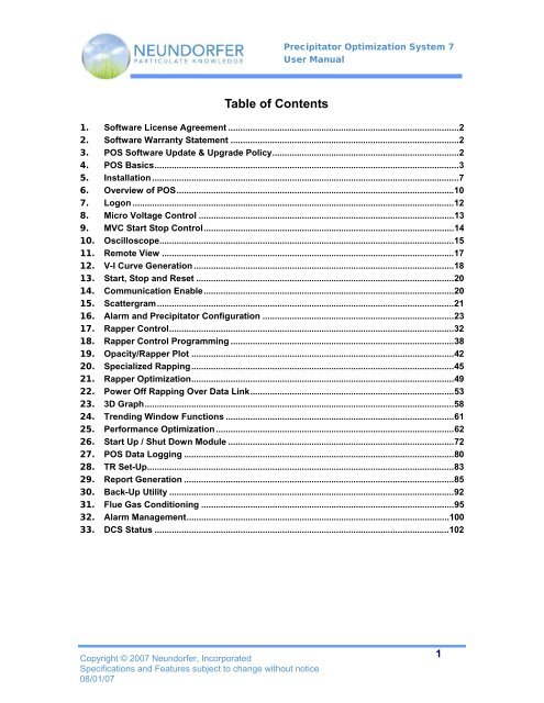
<strong>Precipitator</strong> <strong>Optimization</strong> <strong>System</strong> 7<br />
<strong>User</strong> <strong>Manual</strong><br />
Table of Contents<br />
1. Software License Agreement ..............................................................................................2<br />
2. Software Warranty Statement .............................................................................................2<br />
3. POS Software Update & Upgrade Policy............................................................................2<br />
4. POS Basics............................................................................................................................3<br />
5. Installation .............................................................................................................................7<br />
6. Overview of POS.................................................................................................................10<br />
7. Logon ...................................................................................................................................12<br />
8. Micro Voltage Control ........................................................................................................13<br />
9. MVC Start Stop Control......................................................................................................14<br />
10. Oscilloscope........................................................................................................................15<br />
11. Remote View .......................................................................................................................17<br />
12. V-I Curve Generation ..........................................................................................................18<br />
13. Start, Stop and Reset .........................................................................................................20<br />
14. Communication Enable......................................................................................................20<br />
15. Scattergram.........................................................................................................................21<br />
16. Alarm and <strong>Precipitator</strong> Configuration ..............................................................................23<br />
17. Rapper Control....................................................................................................................32<br />
18. Rapper Control Programming ...........................................................................................38<br />
19. Opacity/Rapper Plot ...........................................................................................................42<br />
20. Specialized Rapping...........................................................................................................45<br />
21. Rapper <strong>Optimization</strong>...........................................................................................................49<br />
22. Power Off Rapping Over Data Link...................................................................................53<br />
23. 3D Graph..............................................................................................................................58<br />
24. Trending Window Functions .............................................................................................61<br />
25. Performance <strong>Optimization</strong>.................................................................................................62<br />
26. Start Up / Shut Down Module ............................................................................................72<br />
27. POS Data Logging ..............................................................................................................80<br />
28. TR Set-Up.............................................................................................................................83<br />
29. Report Generation ..............................................................................................................85<br />
30. Back-Up Utility ....................................................................................................................92<br />
31. Flue Gas Conditioning .......................................................................................................95<br />
32. Alarm Management...........................................................................................................100<br />
33. DCS Status ........................................................................................................................102<br />
Copyright © 2007 <strong>Neundorfer</strong>, <strong>Inc</strong>orporated<br />
Specifications and Features subject to change without notice<br />
08/01/07<br />
1
<strong>Precipitator</strong> <strong>Optimization</strong> <strong>System</strong> 7<br />
<strong>User</strong> <strong>Manual</strong><br />
1. Software License Agreement<br />
The POS software is a copyrighted product of <strong>Neundorfer</strong>, <strong>Inc</strong>. and also contains purchased<br />
copyrighted modules. The <strong>Neundorfer</strong> Software License Agreement protecting <strong>Neundorfer</strong> and its<br />
suppliers specifies that each copy of the POS software provided by <strong>Neundorfer</strong> may be run on a<br />
single PC, with the allowances that copies may be made for backup purposes. The licensee may<br />
move, not copy, the POS software to a different PC than originally installed, but may not transfer<br />
the software to a different owner without written permission from <strong>Neundorfer</strong>, <strong>Inc</strong>.<br />
2. Software Warranty Statement<br />
1. The original manufacturer’s warranty applies to all computer equipment, software and<br />
related hardware. <strong>Neundorfer</strong>, as the original purchaser of the hardware, may intervene<br />
on behalf of a customer to resolve warranty issues with the equipment. The customer<br />
will be required to pay all shipping costs to and from <strong>Neundorfer</strong> incurred in resolving the<br />
warranty issues with the equipment. Additional costs, including but not limited to parts<br />
and labor, which are not covered under the ORIGINAL EQUIPMENT<br />
MANUFACTURER’S WARRANTY shall be paid by the customer.<br />
2. With regard to all POS Equipment manufactured by <strong>Neundorfer</strong>, reference should be<br />
made to <strong>Neundorfer</strong>’s “Standard Terms and Conditions of Sales and Service”.<br />
3. <strong>Neundorfer</strong> does not warrant that the POS application will meet a customer’s needs or<br />
that it will be free from defects.<br />
4. <strong>Neundorfer</strong> shall not be held liable for any damages, data loss or product loss arising<br />
from a customer’s use, misuse or inability to use the POS application.<br />
3. POS Software Update & Upgrade Policy<br />
<strong>Neundorfer</strong> will provide free software updates. Software updates are defined as small<br />
incremental improvements to fix defects and/or add limited additional functionality. <strong>Neundorfer</strong><br />
will not automatically send software updates to all users. <strong>Neundorfer</strong> personnel may at their<br />
discretion and with a customer’s approval, install software updates while at the customer site.<br />
Generally, software updates will only be supplied at the customer’s request. On occasion<br />
software updates will require the purchase or upgrade of third party software. Charges for third<br />
party software will be passed on to the customer.<br />
<strong>Neundorfer</strong> will provide upgrades at a customer’s request as they become available, and charge<br />
for them. A software upgrade is defined as a major functional improvement of the software.<br />
These improvements may be in the form of add on modules to an existing version of POS or an<br />
actual new version of the POS application.<br />
Copyright © 2007 <strong>Neundorfer</strong>, <strong>Inc</strong>orporated<br />
Specifications and Features subject to change without notice<br />
08/01/07<br />
2
<strong>Precipitator</strong> <strong>Optimization</strong> <strong>System</strong> 7<br />
<strong>User</strong> <strong>Manual</strong><br />
4. POS Basics<br />
Components of Overall <strong>System</strong><br />
There are two major components of a typical POS control system. The first component is the<br />
POS application software that runs on personal computers running the Windows operating<br />
system. The second component is the hardware connected to the POS control system. This<br />
hardware may consist of <strong>Neundorfer</strong> equipment including MVC voltage controls, MicroRap rapper<br />
controls, along with PLC equipment for hopper evacuation, soot blowing, and flue gas<br />
conditioning systems.<br />
Specific sub-component information for the <strong>Neundorfer</strong> MVC voltage controls, and MicroRap<br />
rapper controls can be found in their respective manuals.<br />
POS Hardware Components<br />
The <strong>Neundorfer</strong> controls are linked together via an RS-485 multidrop network. The RS-485<br />
interface is built into the rapper controls and voltage controls. On POS computers, the interface<br />
may be an internal card or the output from the computer may be RS-232, which is then converted<br />
to RS-485 by an external converter. For specific details implementing this network refer drawings<br />
supplied with the system. Each device within a family of devices requires a unique address<br />
number on the multi drop network. The voltage control addresses are set on the voltage control<br />
front panel and range from 1 to 255. Each rapper control also requires a unique address number<br />
from 1 through 32, and is set via the hand held programmer supplied with the control. The POS<br />
computer is the master of this network, meaning it is the only device that can initiate a message.<br />
The voltage controls and rapper controls can only send messages after specifically addressed by<br />
POS using their control type and unit number. When the POS computer initiates communication<br />
with a control, POS will wait for one of two events to occur before sending another message.<br />
The first event is a valid response from the control and the second is a communication error. A<br />
communication error will occur if the addressed control does not respond within the allotted time<br />
or the message received is invalid.<br />
For MVC4 voltage controls the data link between the POS computer and the voltage controls<br />
should be a fiber optic link. The fiber optic link is converted to RS-485 at the voltage controls.<br />
The fiber optic link is required to prevent ground loops between the grounded RS-485 cable’s<br />
shield at the PC and the grounded voltage control cabinets.<br />
Many POS software modules require external signals provided by other plant systems. These<br />
inputs can be hardware wired electrical signals such as a 4-20mA input or digital communications<br />
such as OPC or Modbus protocols. How these signals are brought into POS is very plant<br />
dependant and therefore built custom for your installation. There will be hardware drawings<br />
provided for and additional equipment provided for the interface of electrical signals.<br />
Copyright © 2007 <strong>Neundorfer</strong>, <strong>Inc</strong>orporated<br />
Specifications and Features subject to change without notice<br />
08/01/07<br />
3
<strong>Precipitator</strong> <strong>Optimization</strong> <strong>System</strong> 7<br />
<strong>User</strong> <strong>Manual</strong><br />
POS Software Components<br />
Data Logging<br />
POS can be configured to log the following information to disk files:<br />
• Voltage control operating parameters including primary and secondary voltages, power level,<br />
control status (communication error, running, tripped, etc.), spark rate, operating mode and<br />
IE ratio.<br />
• <strong>Precipitator</strong> data including average and total voltage control operating parameters, opacity<br />
signal, load signal and power optimization information.<br />
• Rapper actuations.<br />
• Auxiliary analog and/or digital inputs.<br />
• SO3 <strong>Optimization</strong> actions.<br />
• Soot blower actuations.<br />
Actual data logged in your system will vary depending on which modules were purchased and<br />
how the system is configured.<br />
Status Monitoring<br />
POS monitors the status of individual rapper controls, voltage controls and each rapper in the<br />
system. In the overview screens, each item is color coded for quick identification of its status.<br />
The overview screen is also factory customized to reflect the actual layout of the units it is<br />
controlling. You can also view the voltage control’s operating parameters via the remote face<br />
panel view, bar graphs and trend graphs. The remote face panel view of the voltage control also<br />
allows the user to view the control limits or set points. POS also displays the program number<br />
that is currently running in the rapper controls.<br />
The 3D graph represents a plan view of the precipitator. This graph shows how the overall<br />
precipitator is operating by displaying the selected parameter of each voltage control as a 3D bar.<br />
This screen is useful for locating problem fields in a precipitator and verifying control setup<br />
parameters.<br />
POS also can display the status information of soot blowers, hopper evacuation systems, and<br />
flue gas conditioning systems.<br />
Copyright © 2007 <strong>Neundorfer</strong>, <strong>Inc</strong>orporated<br />
Specifications and Features subject to change without notice<br />
08/01/07<br />
4
<strong>Precipitator</strong> <strong>Optimization</strong> <strong>System</strong> 7<br />
<strong>User</strong> <strong>Manual</strong><br />
Remote Control and Programming<br />
POS can also be used for remote control and programming functions. The functions can be<br />
password protected to allow only authorized users access to them. POS has the ability to start,<br />
stop and reset the voltage controls. Also, all the functionality available to the users at the<br />
control’s face panel is also available in POS via the control’s remote view.<br />
<strong>User</strong>s can also remotely program the MicroRap via the Rapper Control Programming Module<br />
(RCPM). This module allows users to create and save an unlimited number of programs on the<br />
computers hard disk drive for later transfer into any of the six valid user programs of the<br />
MicroRap. <strong>User</strong>s also have the ability to remotely change which program number the rapper<br />
control is executing, reset failed rappers and reset rapper control alarms.<br />
POS also can provide control capability for soot blowers, hopper evacuation systems, and flue<br />
gas conditioning systems.<br />
<strong>Optimization</strong><br />
Performance optimization is probably the most powerful feature of POS. With this feature POS<br />
automatically adjusts the voltage control’s operating limits based on one of two sets of<br />
parameters. The first set is stack opacity and load. With opacity and load optimization, POS<br />
continually adjusts the control’s secondary current limit by a user set percentage of full power.<br />
The number of steps and timing of the steps are all user configurable. POS will lower the total<br />
power of the precipitator until one of three things happen. The first being POS reaching the end<br />
of the optimization program, the second is the opacity limit (user set) is reached which will either<br />
abort optimization altogether or cause optimization to take one step back in the program. The<br />
third item that can cause optimization to abort is a large change in the boiler load.<br />
Performance optimization can also be configured to be based on stack opacity and precipitator<br />
power. This operates similar to opacity and load except precipitator power levels are used<br />
instead of boiler load levels. This type of optimization is most commonly used in cement plants.<br />
MicroRap optimization allows the POS to automatically switch between the six stored MicroRap<br />
programs based on a set of conditions configured by the user.<br />
In SO3 optimization POS will adjust the PPM of SO3 to improve precipitator performance. POS<br />
will then monitor the performance of the precipitator and when conditions warrant, it will begin<br />
tuning the PPM to improve precipitator operation. This system requires an interface to the SO3<br />
controls.<br />
Copyright © 2007 <strong>Neundorfer</strong>, <strong>Inc</strong>orporated<br />
Specifications and Features subject to change without notice<br />
08/01/07<br />
5
<strong>Precipitator</strong> <strong>Optimization</strong> <strong>System</strong> 7<br />
<strong>User</strong> <strong>Manual</strong><br />
External Interfaces<br />
We can supply POS with many types of external interfaces. The first is the analog and digital<br />
input/output interface (see hardware components above). This interface is where most POS<br />
installations receive the opacity and boiler load signals. Other analog and digital signals can be<br />
read by POS, displayed on screen, contain alarm set points and logged to disk. POS can also<br />
output total precipitator power to an analog 4 to 20 ma signal.<br />
Another type of external interface is the Distributed Control <strong>System</strong> (DCS) interface. POS has<br />
the ability to communicate to DCS systems via an Allen-Bradley data highway, Allen-Bradley<br />
DF1, Modbus RTU, Modbus + and GE Series 9030 TCP/IP. These protocols are available from<br />
<strong>Neundorfer</strong> to customers who have purchased DCS interfaces.<br />
POS can also communicate on a wide range of PLC networks. Contact <strong>Neundorfer</strong> with your<br />
specific requirements.<br />
POS will also interface to SO3 injection systems, soot blower control systems and hopper<br />
evacuation controls. All of these POS modules will interface to one or more PLC’s used to<br />
control the related equipment. POS will provide status displays, control functions and in some<br />
cases optimize system performance. All of these interfaces are used with the precipitator<br />
information gather by POS to provide trouble shooting assistance, graphing capabilities, system<br />
alarming and fault indication.<br />
Copyright © 2007 <strong>Neundorfer</strong>, <strong>Inc</strong>orporated<br />
Specifications and Features subject to change without notice<br />
08/01/07<br />
6
<strong>Precipitator</strong> <strong>Optimization</strong> <strong>System</strong> 7<br />
<strong>User</strong> <strong>Manual</strong><br />
5. Installation<br />
The POS software comes pre-installed on the computer. This section should only be needed for<br />
a new installation or after a hard disk failure or system upgrade.<br />
Text that is italicized is typed on the keyboard, text in bold represents screen, window titles or<br />
button names.<br />
Installing VTS<br />
1) Insert VTS CDROM into CD drive.<br />
2) The VTS Installation Wizard should begin. If the Installation program does not begin, from<br />
the Windows Start menu select Run, type in F:\SETUP.EXE where F is the drive letter where<br />
the installation disk is located.<br />
3) Follow the instructions of the Installation Program. The installation key required during<br />
installation of VTS can be found printed on the label of the VTS CDROM. Enter this number<br />
when prompted by the installation program.<br />
4) In the Destination window the destination folder must be C:\VTS. POS will not operate<br />
properly if the path for VTS is not C:\VTS.<br />
5) Follow all remaining steps as prompted by the Installation Program.<br />
6) Continue to the next section to install the POS 7 software.<br />
Installing POS Application<br />
1) VTS must be installed and run as described above.<br />
2) Insert <strong>Neundorfer</strong> POS 7 installation CDROM into CD Drive.<br />
3) The <strong>Neundorfer</strong> Installation screen should appear. If it does not appear, on the Windows<br />
Start menu select Run, type in F:\DEMO32.EXE where F is the drive letter of the CDROM.<br />
4) Select Software, and then Install POS 7. Follow the installation instructions on the screen.<br />
Application and configuration files will automatically be installed into the appropriate<br />
directories under the C:\VTS directory.<br />
Copyright © 2007 <strong>Neundorfer</strong>, <strong>Inc</strong>orporated<br />
Specifications and Features subject to change without notice<br />
08/01/07<br />
7
<strong>Precipitator</strong> <strong>Optimization</strong> <strong>System</strong> 7<br />
<strong>User</strong> <strong>Manual</strong><br />
Adding POS to VTS<br />
Adding POS to VTS need only be done after the initial installation.<br />
Add New Application Window<br />
1) From the Desktop start VTS by doubleclicking<br />
the VTS icon. When the VTS<br />
Application Manager appears, press the<br />
Add New button.<br />
2) In the Add New Application window<br />
select Find Existing, then press OK<br />
button.<br />
3) In the Found Applications window enter<br />
the path to read C:\VTS\POS7, and press<br />
the Enter key. Select the POS application<br />
and press the OK button.<br />
VTS Application Manager<br />
(OPTIONAL INSTRUCTIONS<br />
FOR POS AUTOSTART)<br />
4) In the VTS Application Manager, highlight<br />
the POS line, and press the Properties<br />
button.<br />
5) In the Application Properties window<br />
click on the AutoStart Application box,<br />
then press the OK button.<br />
6) In the VTS Application Manager, press<br />
the Exit button. Now POS will<br />
automatically begin running whenever the<br />
VTS program is started.<br />
Application Properties Screen<br />
Copyright © 2007 <strong>Neundorfer</strong>, <strong>Inc</strong>orporated<br />
Specifications and Features subject to change without notice<br />
08/01/07<br />
8
<strong>Precipitator</strong> <strong>Optimization</strong> <strong>System</strong> 7<br />
<strong>User</strong> <strong>Manual</strong><br />
Windows Display Settings<br />
For POS screens to appear properly on the display the resolution must be set to no less than<br />
1280 x 1024 and the color palette should be set to Highest (32 bit) setting. If the screen<br />
resolution is set to less than 1280 x 1024, then some POS items will be completely or partially off<br />
the display area. Color palettes other than Highest (32 bit) will result in screen items with<br />
unusual colors or no color at all.<br />
Starting POS<br />
From the Desktop or the Start menu run POS by double clicking the POS icon. If POS has been<br />
re-installed or upgraded you may have to click the VTS icon.<br />
If POS is not set to Auto-Start, highlight POS 7 in the VTS Application Manager menu and click<br />
the Run button.<br />
Copyright © 2007 <strong>Neundorfer</strong>, <strong>Inc</strong>orporated<br />
Specifications and Features subject to change without notice<br />
08/01/07<br />
9
<strong>Precipitator</strong> <strong>Optimization</strong> <strong>System</strong> 7<br />
<strong>User</strong> <strong>Manual</strong><br />
6. Overview of POS<br />
POS Main Display<br />
The POS main display is the screen that first appears when starting up your POS. There will be<br />
a page for each precipitator contain in your systems. Some larger precipitators will require more<br />
than one screen to display all the information. This display shows the status of voltage controls,<br />
rapper control, individual rappers and the opacity, load and secondary kilowatts of this<br />
precipitator. Note that the kilowatts are for the entire precipitator, not just the controls displayed<br />
on the single page.<br />
The status of the rappers are color coded. The codes are as follows:<br />
Green : Ready to rap<br />
Red: Has rapped<br />
Magenta: Rapper failed – shorted<br />
Yellow: Rapper Failed – Open<br />
White: Communication Error between POS and the rapper control<br />
This information is also available in the pop up as described in the next paragraph. The shape of<br />
the rappers typically denotes the types of rapper being displayed. Circle rappers represent plate<br />
rappers, square rappers represent wire rappers and diamond represent other types that could<br />
include sonic hors, inlet and outlet baffle rappers or motors type rappers.<br />
Copyright © 2007 <strong>Neundorfer</strong>, <strong>Inc</strong>orporated<br />
Specifications and Features subject to change without notice<br />
08/01/07<br />
10
<strong>Precipitator</strong> <strong>Optimization</strong> <strong>System</strong> 7<br />
<strong>User</strong> <strong>Manual</strong><br />
All screen items are active, meaning you can right or left click on each item to access appropriate<br />
functions for each device. Hovering the mouse over the TR set, rapper, precipitator and the<br />
rapper control icons will activate a pop up for that device. The pop up will display at a minimum<br />
the device ID in the system and some additional information. The rapper icons will display its<br />
name, current status that corresponds to its displayed color, rapper control output number and<br />
the rapper type. The TR set pop up looks like the face panel of the TR control and contains live<br />
data log information. The aux display of this pop up contains the POS configured unit number for<br />
that device. Sample pop ups are displayed below.<br />
Sample Tool Tip for Rapper Icon<br />
update<br />
Sample Tool Tip for Voltage Control Icon<br />
The Page Header, located across the top of the POS display, contains the POS logo and the<br />
Logon button. The Logon Button is located to the right of the Page Header with a time/date<br />
display and alarm indicator. Pressing the bell icon in the alarm indicator will take the user to the<br />
alarm page. Pressing the printer icon will print the currently displayed window to the default<br />
Windows printer.<br />
The Menu - Page bar, across the bottom of the POS display, allows the user to switch between<br />
the various screens. The Menu Button allows the user to access all available screens.<br />
The Page Bar is programmable to display the most used screens. The Page bar also has a<br />
Page Back () buttons on the right hand side of the button bar. These<br />
buttons page through the most recently displayed pages. The buttons to add or remove screen<br />
buttons from the Page bar are located to left of the page buttons and are labeled with + or -.<br />
Clicking these buttons adds or removes the currently visible page from the page bar.<br />
Copyright © 2007 <strong>Neundorfer</strong>, <strong>Inc</strong>orporated<br />
Specifications and Features subject to change without notice<br />
08/01/07<br />
11
<strong>Precipitator</strong> <strong>Optimization</strong> <strong>System</strong> 7<br />
<strong>User</strong> <strong>Manual</strong><br />
7. Logon<br />
1) Press the Logon Button.<br />
2) Enter logon <strong>User</strong>name and press Tab key or<br />
click on the next line with the mouse.<br />
3) Enter user Password and press Enter or click<br />
on the OK button with the mouse..<br />
Press the Cancel button if a mistake has been<br />
made during log on.<br />
After successfully logging on, the username will be<br />
substituted for Logon in the button.<br />
Logon Window<br />
POS ships with the default user name and password of NEQ. This will grant the user complete<br />
access to all POS functions.<br />
Copyright © 2007 <strong>Neundorfer</strong>, <strong>Inc</strong>orporated<br />
Specifications and Features subject to change without notice<br />
08/01/07<br />
12
<strong>Precipitator</strong> <strong>Optimization</strong> <strong>System</strong> 7<br />
<strong>User</strong> <strong>Manual</strong><br />
8. Micro Voltage Control<br />
MVC Icons<br />
On the Plan View window, each individual MVC is<br />
represented by an icon. The icons have two different<br />
drawing methods, the POS 7 style or the POS 6 style.<br />
The user can toggle between the two icon display types<br />
by right clicking on the TR set icon and selecting the POS<br />
7 icon style enable line on the menu that appears. The<br />
POS 7 style icon has live bar graph displays of current<br />
operating data. The bar graphs are switched to text<br />
displays when the TR set is off, trip or not<br />
communicating.<br />
POS 7 Style<br />
icons<br />
The POS 6 style icons resemble the plan view of a TR<br />
set. The POS 6 icons are drawn with either one or both<br />
bushings active and in a position according to your<br />
individual precipitator’s actual layout. If the rotation is not<br />
correct the user can change it by right clicking on the TR<br />
set and selecting Properties on the menu that appears.<br />
Select the Display tab once in the TR set properties and<br />
adjust the rotation as desired. The color of the POS 6<br />
style icons represent it’s current state and is set up as<br />
follows:<br />
Green: Stopped Red: Running<br />
Yellow: Tripped White: Communication Error<br />
POS determines wither the icon is a single or dual<br />
bushing TR set from the MVC configuration and adjusts<br />
the icon display appropriately. For a POS 6 style icon, if<br />
the secondary voltage of a bushing is below 1000 V then<br />
that bushing will be colored in the “Off” state.<br />
Pressing the T/R icon will display the MVC control menu.<br />
The MVC name will appear in the window header. This<br />
window contains buttons for each POS feature used in<br />
monitoring or controlling a TR set. These features are<br />
discussed in the sections below.<br />
POS 6 style<br />
icons<br />
MVC Control Menu<br />
Copyright © 2007 <strong>Neundorfer</strong>, <strong>Inc</strong>orporated<br />
Specifications and Features subject to change without notice<br />
08/01/07<br />
13
<strong>Precipitator</strong> <strong>Optimization</strong> <strong>System</strong> 7<br />
<strong>User</strong> <strong>Manual</strong><br />
9. MVC Start Stop Control<br />
The MVC controls can be started, stopped and reset from the control menu on an individual basis<br />
by pressing the appropriate button. The voltage controls and POS has interlocking set up so that<br />
if a control is stopped it must then be restarted from the same location, meaning if POS stops it<br />
then POS must start it or if stopped locally then it must be started locally. This is to prevent<br />
inadvertent start up of the control from another source if someone has shut it down to work within<br />
the cabinet. Controls can be started and stopped as an entire precipitator through the<br />
precipitator menu.<br />
Copyright © 2007 <strong>Neundorfer</strong>, <strong>Inc</strong>orporated<br />
Specifications and Features subject to change without notice<br />
08/01/07<br />
14
<strong>Precipitator</strong> <strong>Optimization</strong> <strong>System</strong> 7<br />
<strong>User</strong> <strong>Manual</strong><br />
10. Oscilloscope<br />
Pressing the Oscilloscope button on the MVC control menu. This widow will display traces<br />
similar to those that may be captured by an actual oscilloscope.<br />
The large grid area of the window is where POS plots the scope waveforms. The display<br />
contains four waveforms each one plotting the signal selected by the drop down lists along the<br />
right edge of the oscilloscope window. The white vertical line on the graph is the position of the<br />
trigger point when the data is plotted. Clicking the mouse button along the top edge of the graph<br />
will move the trigger point line.<br />
The Print button opens a print preview window. In the print preview window the user can view<br />
what the printout will look like and choose to print a hardcopy using a configured windows printer.<br />
Pressing the Close button closes the oscilloscope window.<br />
Copyright © 2007 <strong>Neundorfer</strong>, <strong>Inc</strong>orporated<br />
Specifications and Features subject to change without notice<br />
08/01/07<br />
15
<strong>Precipitator</strong> <strong>Optimization</strong> <strong>System</strong> 7<br />
<strong>User</strong> <strong>Manual</strong><br />
The Start button begins the data capture and transfer from the voltage control to the POS<br />
computer. After pressing the Start the user can change the scope setup and begin another trace<br />
by pressing the start button again. This action aborts the running data capture and begins a new<br />
one. The line of text at the bottom of the trace contains a status message and the setup<br />
information for the displayed scope trace.<br />
The Select MVC dropdown list contains a list of all the voltage controls on the precipitator. The<br />
control selected on this list is the control that will generate the oscilloscope traces.<br />
The Trace Type drop down list lets the user select what type of data the user wants to display.<br />
High Speed Data displays traces like those captured with a traditional oscilloscope. The signals<br />
that can be graphed include Primary Current, Primary Voltage, Secondary Current,<br />
Secondary KVa, Secondary KVb, and Conduction Angle. The Primary Averages trace type<br />
is similar to a trend graph or a graph of face panel data except at a much higher data capture<br />
speed. The signals that can be graphed include Primary Current, Primary Voltage,<br />
Secondary Current, and Conduction Angle. The KvMin/Max plots a graph of the secondary<br />
voltage minimum and maximum values of each half cycle of the line. The signals that can be<br />
graphed include Secondary Current, Secondary Kva min, Secondary KVb max, and<br />
Conduction Angle.<br />
The Trigger dropdown list is where the user selects which event the control will begin its data<br />
capture. The list includes Primary Current Limit, Primary Over Voltage Limit, Secondary<br />
Current Limit, KV Limit, Conduction Angle Limit and Spark. The trace generation is event<br />
driven and the user must select a trigger event that actually occurs in the MVC for the data<br />
capture to begin and be transferred to POS.<br />
The Sweep Speed drop down list is where the user selects the rate at which the data will be<br />
gathered. This list will vary depending on the Trace Type selected.<br />
Pressing the Store button saves the scope data to the CSV directory as a CSV file. The<br />
Retrieve button brings that data back into POS for display. You can load the raw scope CSV<br />
data into a spreadsheet application, the file is typically stored in the c:\vts\pos7\csv directory.<br />
The Print button is used to send the graph image to any configured printer in the operating<br />
system.<br />
Copyright © 2007 <strong>Neundorfer</strong>, <strong>Inc</strong>orporated<br />
Specifications and Features subject to change without notice<br />
08/01/07<br />
16
<strong>Precipitator</strong> <strong>Optimization</strong> <strong>System</strong> 7<br />
<strong>User</strong> <strong>Manual</strong><br />
11. Remote View<br />
Pressing the Remote View button<br />
opens a window showing an MVC<br />
display panel with current operating<br />
values. This window operates<br />
identically to the actual voltage control<br />
display panel. Buttons that change<br />
operating set points are password<br />
protected. For MVC operation please<br />
refer to the user manual that shipped<br />
with the control.<br />
MVC Remote View<br />
Copyright © 2007 <strong>Neundorfer</strong>, <strong>Inc</strong>orporated<br />
Specifications and Features subject to change without notice<br />
08/01/07<br />
17
<strong>Precipitator</strong> <strong>Optimization</strong> <strong>System</strong> 7<br />
<strong>User</strong> <strong>Manual</strong><br />
12. V-I Curve Generation<br />
Pressing the V-I Curve button on the MVC control menu will open the VI curve window.<br />
The T/R set initially selected on the plan view screen will be the default used to generate a V-I<br />
curve. Other TR sets can be added using the TR selection drop down list.<br />
V-I Curve Window<br />
To add additional T/R sets or change an existing T/R set using the V-I Curve window drop down<br />
list:<br />
1) Press the arrow next to the pen Status box in your choice of color and a drop down list of<br />
T/R sets in the precipitator will be displayed.<br />
2) Select the T/R set by highlighting the appropriate T/R set name.<br />
Copyright © 2007 <strong>Neundorfer</strong>, <strong>Inc</strong>orporated<br />
Specifications and Features subject to change without notice<br />
08/01/07<br />
18
<strong>Precipitator</strong> <strong>Optimization</strong> <strong>System</strong> 7<br />
<strong>User</strong> <strong>Manual</strong><br />
Pressing the Set Axis button opens a window that allows the user to<br />
change both current and voltage scales. The scales can be set to<br />
auto which causes to software to choose the scale to display the<br />
graph in or the can be set to pre-selected scales. The set axis widow<br />
also allows the user to select the VI curve to graph in KV vs. mA or<br />
KV vs. current density. To utilize the current density option the user<br />
must enter the total collecting plate area for each TR in the TR set<br />
properties, described elsewhere in this manual.<br />
Pressing the Details button to the right of T/R set’s name expands<br />
the view area for that pen to display the details of that pen.<br />
Pressing the Curve Type arrow will display a drop down list of live<br />
and saved V-I curves for the T/R set selected.<br />
Pressing the Start button will start generation of the curve for the<br />
selected T/R set. Only one V-I curve should be generated at a time.<br />
Set Axis Window<br />
The status of the curve for a specific T/R set is indicated by text in the<br />
pen status box to the right of the T/R set’s name and below the Curve<br />
Type box, other information regarding the selected T/R set is<br />
displayed in these areas also.<br />
Sample Curve Types<br />
The Visible check box will display the selected V-I curve when checked and hide it when blank.<br />
The Comment field allows the user to write a text message comment for the selected VI curve<br />
that will be displayed on the printout.<br />
Pressing the Abort button will stop the curve generation.<br />
Pressing the Save button will save the displayed V-I curve by date. The V-I curve datais saved to<br />
the CSV directory as a CSV file. You can load the raw V-I curve CSV data into a spreadsheet<br />
application, the file is typically stored in the c:\vts\pos7\csv directory.<br />
Pressing the Print button opens a Print Preview window. The first page of the preview contains<br />
the curves displayed on the graph along with the comments. The remaining pages display tables<br />
of the primary current and secondary voltage of the T/R Set’s that were recorded during the VI<br />
Curve generation. Pressing the Print All or Print Page button can print a hard copy.<br />
Pressing the Close button will close the window.<br />
Copyright © 2007 <strong>Neundorfer</strong>, <strong>Inc</strong>orporated<br />
Specifications and Features subject to change without notice<br />
08/01/07<br />
19
<strong>Precipitator</strong> <strong>Optimization</strong> <strong>System</strong> 7<br />
<strong>User</strong> <strong>Manual</strong><br />
13. Start, Stop and Reset<br />
The Start, Stop, and Reset functions are in the lower half of the MVC<br />
Control Menu. Again, this menu appears when you click on the<br />
appropriate MVC icon in the plan view of the precipitator.<br />
Pressing the Start button will start the selected voltage control.<br />
Pressing the Stop button will stop the selected voltage control.<br />
Pressing the Reset button will reset the selected voltage control after a<br />
trip has occurred.<br />
Starting and Stopping MVCs is a password protected function. You will<br />
have to log in before gaining access to this function.<br />
As a safety feature, the controls must be started from the same location<br />
in which they were stopped.<br />
MVC Control Menu<br />
14. Communication Enable<br />
Right clicking the T/R set icon will display a configuration menu, with a<br />
Communication Enable check off item. When communication is<br />
disabled, POS will not attempt any communication with that control and<br />
icon will turn black or display DIS text within the icon. This is useful to<br />
free up data link time that would otherwise be used waiting for a<br />
nonfunctioning control to respond to POS messages.<br />
T/R Set Configuration<br />
Copyright © 2007 <strong>Neundorfer</strong>, <strong>Inc</strong>orporated<br />
Specifications and Features subject to change without notice<br />
08/01/07<br />
20
<strong>Precipitator</strong> <strong>Optimization</strong> <strong>System</strong> 7<br />
<strong>User</strong> <strong>Manual</strong><br />
15. Scattergram<br />
The scattergram function is accessible through the precipitator menu. The scattergram is a<br />
graph that shows how factors relate to each other on an XY plane. This is visual, not statistical,<br />
and is used when it is necessary to compare two factors that are related.<br />
Scattergram Window<br />
The Scattergram plot can graph the following precipitator parameters:<br />
• Load<br />
• Opacity<br />
• primary average volts<br />
• primary total amps<br />
• primary total kilowatts<br />
• secondary total amps<br />
• secondary average Kva<br />
• secondary average KVb<br />
• secondary total KW<br />
• secondary average angle<br />
• secondary average sparks<br />
These parameters may be selected for either the X-axis or the Y-axis via drop down lists.<br />
Copyright © 2007 <strong>Neundorfer</strong>, <strong>Inc</strong>orporated<br />
Specifications and Features subject to change without notice<br />
08/01/07<br />
21
<strong>Precipitator</strong> <strong>Optimization</strong> <strong>System</strong> 7<br />
<strong>User</strong> <strong>Manual</strong><br />
The data is retrieved from Log files and can span any historical range. Select Start and or End<br />
Times by highlighting the time and/or date. Then use the arrows adjust the time and/or date<br />
settings to the desired setting. Pressing the Start button will retrieve data and display it as points<br />
on the screen.<br />
The Plot Status is displayed below the Start button.<br />
Pressing the Print button opens a Print Preview window. This window displays the graph and a<br />
table of values of the data points. Pressing Print All or Print Page buttons prints a hard copy of<br />
the curve for future use.<br />
Pressing the Set Axis button opens a window that allows the user to set the scales to auto which<br />
causes to software to choose the scale to display the graph in or they can be set to pre-selected<br />
scales.<br />
Copyright © 2007 <strong>Neundorfer</strong>, <strong>Inc</strong>orporated<br />
Specifications and Features subject to change without notice<br />
08/01/07<br />
22
<strong>Precipitator</strong> <strong>Optimization</strong> <strong>System</strong> 7<br />
<strong>User</strong> <strong>Manual</strong><br />
16. Alarm and <strong>Precipitator</strong> Configuration<br />
Clicking on the Alarm Settings menu items in the rapper control, TR set and precipitator menus<br />
will open up the <strong>Precipitator</strong> Data Display window. This module is used to describe the<br />
precipitator to POS and configure all alarms for the precipitator, voltage controls and rapper<br />
controls.<br />
<strong>Precipitator</strong> Data Display Window – Field Data Tab<br />
Editing Field Data<br />
Editing precipitator data is a password protected function. <strong>User</strong>s need to log in with the proper<br />
security level before making any changes. When finished be sure to press the Accept button to<br />
save changes. Pressing the X button to the right edge of the field clears all values from that field.<br />
All of the information entered on this screen is used by POS to determine how much to offset the<br />
rapper actuations to allow for the time it takes the ash to travel from rapper location to the opacity<br />
meter.<br />
Enter a name for the field in the Field Name field. This name will be used by POS to create the<br />
names for the fields in the Rapper/Opacity Plot and in the rapper properties.<br />
Enter the number of gas passages in the field in the Number of Gas Passages field.<br />
Enter the number of inches between plates in the field in the Plate Spacing field.<br />
Copyright © 2007 <strong>Neundorfer</strong>, <strong>Inc</strong>orporated<br />
Specifications and Features subject to change without notice<br />
08/01/07<br />
23
<strong>Precipitator</strong> <strong>Optimization</strong> <strong>System</strong> 7<br />
<strong>User</strong> <strong>Manual</strong><br />
Enter the height of the plates in the Plate Height field.<br />
Enter the length of the field in the Plate Length field.<br />
Calculate the distance from the center of the field to the outlet of the precipitator. Enter this value<br />
in the Centerline to Outlet field.<br />
The value for Cross Sectional Area is calculated by POS using the following equation:<br />
Number of gas passages * Plate Spacing * Plate Height.<br />
The value for Gas Velocity is calculated by POS using the following equation:<br />
Total Gas Flow / Cross Sectional Area<br />
The value for Field Plate Area is calculated by POS using the following equation:<br />
Plate Height * Plate Length * Number of Gas Passages * 2<br />
The value for Field Treat Time is calculated by POS using the following equation:<br />
Plate Length / Gas Velocity<br />
Enter a value for Total Gas Flow in ACFM (actual cubic feet per minute). This value will help<br />
determine other values such as the treatment time and SCA.<br />
Enter a value for Opacity Meter Delay Time in seconds. This value should be the number of<br />
seconds it takes for gas to travel from the precipitator to the stack opacity meter.<br />
The values for SCA and <strong>Precipitator</strong> Treatment Time are calculated by POS based on data<br />
entered in other fields.<br />
Be sure to press the Accept button to save any changes.<br />
Copyright © 2007 <strong>Neundorfer</strong>, <strong>Inc</strong>orporated<br />
Specifications and Features subject to change without notice<br />
08/01/07<br />
24
<strong>Precipitator</strong> <strong>Optimization</strong> <strong>System</strong> 7<br />
<strong>User</strong> <strong>Manual</strong><br />
<strong>Precipitator</strong> Alarm Settings<br />
Click on the <strong>Precipitator</strong> Alarm Settings tab to view and edit precipitator alarms. These alarms<br />
are for the entire precipitator in which they are configured. You will need to set these in each<br />
configured system on the precipitator.<br />
<strong>Precipitator</strong> Alarms Tab<br />
Press the Edit button to make changes to the alarm settings.<br />
Use the drop down lists to set the priority of the alarms. The priority can be one of the following:<br />
• Disabled: The alarm condition is disabled. There will be no alarm.<br />
• Event: The condition will cause a low priority event entry in the alarm log.<br />
• Pop-Up: The condition will cause a pop-up window to appear and a low priority alarm.<br />
• Medium: The condition will cause a medium priority alarm entry in the alarm log.<br />
• High: The condition will cause a high priority alarm entry in the alarm log.<br />
Enter a value in the Opacity Above X % to set an alarm condition when opacity rises above the<br />
entered value.<br />
To alarm a specific change in opacity over a set time then enter values in the Opacity increases<br />
X % in Y Hours fields.<br />
To alarm on a specific boiler load then set the drop down list to select Greater/Less Than and<br />
enter a load value in Megawatts.<br />
Copyright © 2007 <strong>Neundorfer</strong>, <strong>Inc</strong>orporated<br />
Specifications and Features subject to change without notice<br />
08/01/07<br />
25
<strong>Precipitator</strong> <strong>Optimization</strong> <strong>System</strong> 7<br />
<strong>User</strong> <strong>Manual</strong><br />
The <strong>Precipitator</strong> Power below X KW is used to alarm on a minimum precipitator power level.<br />
To alarm a specific change in precipitator power over a set time then enter values in the<br />
<strong>Precipitator</strong> Power drops X KW in Y Hours fields.<br />
POS can be configured to e-mail alarms to users. The to and from addresses must contain a<br />
valid internet e-mail address, for example user@domain.com. The server entry should contain<br />
the name of your SMTP server or other server that you can authenticate to.<br />
Copyright © 2007 <strong>Neundorfer</strong>, <strong>Inc</strong>orporated<br />
Specifications and Features subject to change without notice<br />
08/01/07<br />
26
<strong>Precipitator</strong> <strong>Optimization</strong> <strong>System</strong> 7<br />
<strong>User</strong> <strong>Manual</strong><br />
Global TR Set Alarm Settings<br />
Click on the Global TR Set Alarms tab to view and edit TR Set alarms. These alarms are<br />
common across all TR set on the configured precipitator. You will need to set these in each<br />
configured precipitator.<br />
Global TR Set Alarms Tab<br />
The TR Set/Com Port Communication alarm priority setting is used to configure POS to alarm<br />
on any voltage control communication failures and communication port problems.<br />
The TR Set Trip Status alarm priority setting is used to configure POS to alarm on a TR Set trip.<br />
The TR Sets in a Lane off or Tripped setting configures POS to alarm after a specific number of<br />
TR sets in a precipitator lane have been turned off or tripped. This alarm uses the same lane<br />
information that is used to build the 3D graphs.<br />
The TR Sets in a Field off or Tripped setting configures POS to alarm after a specific number of<br />
TR sets in a precipitator field have been turned off or tripped. This alarm uses the same field<br />
information that is used to build the 3D graphs.<br />
The TR Sets in a <strong>Precipitator</strong> off or Tripped setting configures POS to alarm after a specific<br />
number of TR sets in a precipitator have been turned off or tripped.<br />
The TR Set Control Tripped X tines in Y hours configures POS to alarm if a control trips a<br />
specific number of times in a given time frame.<br />
Copyright © 2007 <strong>Neundorfer</strong>, <strong>Inc</strong>orporated<br />
Specifications and Features subject to change without notice<br />
08/01/07<br />
27
<strong>Precipitator</strong> <strong>Optimization</strong> <strong>System</strong> 7<br />
<strong>User</strong> <strong>Manual</strong><br />
The TR Set Local/Remote hand switch change alarm setting configures POS to alarm when<br />
control is toggled between remote and local modes.<br />
The TR Set Power changes from <strong>Precipitator</strong> by X% in Y hours alarm setting configures POS<br />
to alarm if a TR set power level drifts from the total precipitator power level in a given time frame.<br />
The TR Set Spark Rate is X% over Baseline Setpoint configures POS to alarm if a voltage<br />
control is sparking a given percentage above its spark rate set point.<br />
Individual T/R Set Alarm<br />
Click on the Individual TR Set Alarms tab to view and edit TR Set alarms. This page allows you<br />
to configure alarms for TR electrical parameters for each individual TR. They can be set the<br />
same across the precipitator or individually for each TR set. You will need to set these in each<br />
configured precipitator.<br />
Individual T/R Set Alarms Tab<br />
To set up these alarms first select the edit button. Then in the Configuration section select the<br />
alarm priority that you would like. The Set all controls equal check box allows for the settings in<br />
one control to be set identically in all controls on this precipitator. Leaving this box unchecked<br />
Copyright © 2007 <strong>Neundorfer</strong>, <strong>Inc</strong>orporated<br />
Specifications and Features subject to change without notice<br />
08/01/07<br />
28
<strong>Precipitator</strong> <strong>Optimization</strong> <strong>System</strong> 7<br />
<strong>User</strong> <strong>Manual</strong><br />
will require each control to be set individually. The drop list just below allows the user to set the<br />
alarm to trigger on an instantaneous value are a rolling average. The Alarm On check boxes<br />
allows the user to select which secondary electrical parameters to monitor. Put a check in one or<br />
more boxes and that will activate the checked parameter in the TR icons below. The alarm will<br />
activate anytime the selected parameter drops below the number entered into the edit field.<br />
The individual TR Alarm type is unique from other alarms in that it can also generate a CSV file<br />
for reporting purposes. To configure the report put a check in the “On alarm, create CSV file in”<br />
checkbox. Enter the path statement for where POS will create the report in the field to the right<br />
on the checkbox. You can also select the path by pressing the Browse button. The spin box<br />
below selects how much data prior to the alarm that will be included in the CSV report. The<br />
Disable after n alarm(s) in an hour spin box allows the user to limit the number of CSV files that<br />
will be generated in an hour.<br />
Copyright © 2007 <strong>Neundorfer</strong>, <strong>Inc</strong>orporated<br />
Specifications and Features subject to change without notice<br />
08/01/07<br />
29
<strong>Precipitator</strong> <strong>Optimization</strong> <strong>System</strong> 7<br />
<strong>User</strong> <strong>Manual</strong><br />
Rapper/Control Alarm Settings<br />
Click on the Rapper/Control Alarm Settings tab to view and edit Rapper and MicroRap alarms.<br />
Rapper Control Alarm Tab<br />
The Rapper Controller Communication Status alarm priority setting is used to configure POS<br />
to alarm on any rapper control communication failures and communication port problems.<br />
The Number of Failed Rappers exceeds Controllers limit will alarm when the actual number of<br />
failed rappers on a MicroRap control is greater than the number used to generate the MicroRap<br />
rapper fail alarm. The rapper fail alarm is a MicroRap generated alarm and the number of failed<br />
rappers is part of the MicroRap system configuration.<br />
POS can be configured to alarm when the MicroRap activates the Rapper Fail alarm. The<br />
rapper fail alarm is a MicroRap generated alarm and the number of failed rappers is part of the<br />
MicroRap system configuration.<br />
Copyright © 2007 <strong>Neundorfer</strong>, <strong>Inc</strong>orporated<br />
Specifications and Features subject to change without notice<br />
08/01/07<br />
30
<strong>Precipitator</strong> <strong>Optimization</strong> <strong>System</strong> 7<br />
<strong>User</strong> <strong>Manual</strong><br />
Function Start Interaction<br />
Click on the Function Start Interaction tab to configure how different POS functions will interact<br />
with one another. These setting are designed specifically for different POS functions that my<br />
conflict with on another. For example, the performance optimization function lowers precipitator<br />
power while the rapper optimization may be using precipitator power to control rapping. Both of<br />
these function obviously conflict with each other and the user should consider how they want<br />
them to interact with one another.<br />
Rapper Control Alarm Tab<br />
The horizontal axis of this screen represents the running function and the vertical axis represents<br />
the starting function. Where the two axis meet on the grid is the interaction setting. The<br />
interaction settings are:<br />
Start Allowed – This is the default setting for all functions in POS. This setting allows both<br />
functions to run simultaneously.<br />
Start Prohibited – This setting will not allow the starting function to begin.<br />
Stop with Prompt – This setting will stop the running function and will provide the user with a<br />
message stating that the running function will be stopped.<br />
Stop with No Prompt – This setting will stop the running function and not provide the user with a<br />
message that the running function will be stopped.<br />
Copyright © 2007 <strong>Neundorfer</strong>, <strong>Inc</strong>orporated<br />
Specifications and Features subject to change without notice<br />
08/01/07<br />
31
<strong>Precipitator</strong> <strong>Optimization</strong> <strong>System</strong> 7<br />
<strong>User</strong> <strong>Manual</strong><br />
The Set Defaults button allows you to make your settings the default settings. The Use<br />
Defaults sets all the settings back to their default values that you created by pressing the set<br />
defaults button.<br />
17. Rapper Control<br />
Clicking on the Status item in the rapper control menu will display the Rapper Control Status<br />
window. The rapper control name will appear in the select control box.<br />
Note: The program select thumb wheel switch on the MicroRap face panel must be in position 0<br />
to remotely switch between the 6 stored MicroRap programs.<br />
Rapper Control Status – Status Tab<br />
Functionality<br />
The MicroRap Control Dialog displays the status of the selected rapper Control. It can also be<br />
used for program switching, resetting control alarms, and viewing, editing, and creating rapping<br />
programs.<br />
Copyright © 2007 <strong>Neundorfer</strong>, <strong>Inc</strong>orporated<br />
Specifications and Features subject to change without notice<br />
08/01/07<br />
32
<strong>Precipitator</strong> <strong>Optimization</strong> <strong>System</strong> 7<br />
<strong>User</strong> <strong>Manual</strong><br />
If there are more than one Rapper Controllers<br />
attached to your precipitator, use the Select<br />
Control dropdown list to select the correct<br />
rapper control. All functions used in the Control<br />
Dialog affect only the selected Rapper Controller.<br />
Select Control Dropdown List<br />
Copyright © 2007 <strong>Neundorfer</strong>, <strong>Inc</strong>orporated<br />
Specifications and Features subject to change without notice<br />
08/01/07<br />
33
<strong>Precipitator</strong> <strong>Optimization</strong> <strong>System</strong> 7<br />
<strong>User</strong> <strong>Manual</strong><br />
Status Tab<br />
The Status tab displays current information about the selected rapper controller.<br />
Status Tab<br />
The Control box contains the rapper control name, status and alarm indicators, and displays the<br />
number of failed rappers. The Suspend button can be used to pause the rapping program.<br />
Pressing the Resume button will resume rapping sequence where the program left off. External<br />
inputs from the DCS interface or through an additional digital input can also be used to suspend<br />
and resume rapping. Pressing the Reset Alarms button will reset the alarms actuated within the<br />
rapper control. The Reset Failed button resets the status of rappers that failed to operate<br />
properly in the last rapping cycle to a ready status for the next rapping cycle.<br />
Note: Suspend/Resume rapping does not turn the actual control on or off. <strong>User</strong>s must use the<br />
MicroRap’s On/Off switch if they are going to work on the control itself or individual rappers.<br />
The rapper program number that is currently running is displayed in the Current Program<br />
display. To select a new program, use the up and down arrows to change the number in the<br />
New Program display box. If the program number you want to run is different than the program<br />
being currently run, then the button to the right has a Start label. Pressing the Start button will<br />
begin executing that program number. If the program number you want to run is the same as the<br />
program being currently run, then the button to the right has a Restart label. Pressing the<br />
Restart button will reload the active program from the MicroRap’s EPROM only if the two<br />
programs are different. If the program being currently executed by the MicroRap is the same as<br />
the program stored in the MicroRap’s EPROM, pressing Restart will have no effect.<br />
Copyright © 2007 <strong>Neundorfer</strong>, <strong>Inc</strong>orporated<br />
Specifications and Features subject to change without notice<br />
08/01/07<br />
34
<strong>Precipitator</strong> <strong>Optimization</strong> <strong>System</strong> 7<br />
<strong>User</strong> <strong>Manual</strong><br />
The Rapper <strong>Optimization</strong> and Power Off Rapping contains the ON/OFF status of those<br />
modules. The Current Active POR program field contains the POR program name of the<br />
currently active POR program. This field will be blank in no program is active.<br />
Rapper Program Management (Program Transfer Tab)<br />
The Program Transfer tab is used to manage the Rapper Programs on the selected rapper<br />
controller. This tab can be used to transfer programs from the controller or disk file to another<br />
program number in the controller, overwrite a disk file or create a new file. This is completed by<br />
selecting the appropriate From item and To item and then pressing the Transfer button.<br />
These functions are used to transfer rapping program sequence and timing data between the<br />
rapper controller and the POS computer. The MicroRap only executes programs that are stored<br />
locally at the control. The current design of the MicroRap allows for six (6) programs to be stored<br />
at once. You need to specify which of the six (6) programs you wish to transfer to or from the<br />
computer.<br />
Rapper programs stored on the hard drive of the POS computer can have any file name with the<br />
extension of .PGM and there is no limit to the number of programs that can be stored on disk.<br />
The default directory for POS programs is C:\VTS\pos7\pgm.<br />
Program Select Tab<br />
The Print Rapper Program allows you to print rapper programs from three different sources.<br />
These sources are a specific Controller Program number, a Disk File or the Last Program<br />
Transferred to or from the rapper control. Select the appropriate source and press the Print<br />
button. To delete a rapper program disk file, select the file name from the drop list in the Rapper<br />
Program Delete section and then press the Delete button.<br />
Copyright © 2007 <strong>Neundorfer</strong>, <strong>Inc</strong>orporated<br />
Specifications and Features subject to change without notice<br />
08/01/07<br />
35
<strong>Precipitator</strong> <strong>Optimization</strong> <strong>System</strong> 7<br />
<strong>User</strong> <strong>Manual</strong><br />
The Program Wizard button takes you to the rapper control programming wizard described<br />
elsewhere in this manual.<br />
Copyright © 2007 <strong>Neundorfer</strong>, <strong>Inc</strong>orporated<br />
Specifications and Features subject to change without notice<br />
08/01/07<br />
36
<strong>Precipitator</strong> <strong>Optimization</strong> <strong>System</strong> 7<br />
<strong>User</strong> <strong>Manual</strong><br />
<strong>System</strong> Parameter Transfer<br />
<strong>System</strong> Transfer Tab<br />
<strong>System</strong> Parameters are for the configuration of the rapper control setup information and is<br />
independent of rapper programs. <strong>System</strong> parameters include rapper type, the number of retries<br />
for failed rappers and line frequency. The system parameters can be edited by right clicking the<br />
rapper control icon and selecting properties from the menu or in the POS Points.MDB file.<br />
When editing the system configuration it is always best to insure that the rapper types<br />
are still set correctly in the MicroRap. This can be done with the hand held terminal. If<br />
the rapper types are not correct, you run the risk of burning up rapper coils of impact<br />
type rappers.<br />
Send to Control - Transfers system parameters from the POS computer to the rapper controller.<br />
Get from Control - Transfers system parameters from the MicroRap to the POS computer.<br />
If you would like to compare the POS and MicroRap system parameters before uploading or<br />
downloading them, we recommend that you print the system parameters out using the printing<br />
function. The Rapper Controller Parameter Print allows you to print rapper programs from three<br />
different sources. These sources are a specific Controller Parameters number, a Disk<br />
Parameters or the Last Parameters Transferred to or from the rapper control. Select the<br />
appropriate source and press the Print button.<br />
Copyright © 2007 <strong>Neundorfer</strong>, <strong>Inc</strong>orporated<br />
Specifications and Features subject to change without notice<br />
08/01/07<br />
37
<strong>Precipitator</strong> <strong>Optimization</strong> <strong>System</strong> 7<br />
<strong>User</strong> <strong>Manual</strong><br />
18. Rapper Control Programming<br />
As with all the wizards in POS, there is text on each screen that describes what needs to be set<br />
on that screen and its function. The first screen as shown below, the user must select what<br />
program to start with. If you want to start with a blank program then press the Blank Program<br />
button. The other sources are a disk file or from the controller. Pressing the MicroRap<br />
Configuration Wizard lets the user edit the MicroRap system parameter in a wizard format.<br />
Field Data Section<br />
This is where the timing and anti-coincidence parameters are set for each field in the rapper<br />
control. To edit a setting, click on that appropriate item and POS will provide the controls<br />
necessary to set a valid value.<br />
Copyright © 2007 <strong>Neundorfer</strong>, <strong>Inc</strong>orporated<br />
Specifications and Features subject to change without notice<br />
08/01/07<br />
38
<strong>Precipitator</strong> <strong>Optimization</strong> <strong>System</strong> 7<br />
<strong>User</strong> <strong>Manual</strong><br />
The Field Enable parameter is used by the MicroRap to enable and disable rapping in a<br />
particular field. You must have valid sequence data to enable a field.<br />
Note: This must be set to Y for the field to run.<br />
Lane Wait, if turned on, prevents two rappers in the same lane from rapping at the same time.<br />
The Lane Wait sets the time delay for rapper sequencing in a lane. Use the drop down list to set<br />
the Lane Wait time from 0.5 Sec to 53 Sec or to off.<br />
POR Lead Time sets the time between activation of the Power Off Rapping signal sent to the<br />
Micro Voltage Control and the signal sent to operate the rapper. Use the drop down list to set the<br />
POR Lead Time from 0.5 Sec to 53 Sec or off to disable lead time.<br />
Start Delay sets a delay between the time the field is to begin rapping and when the program is<br />
first begun. Use the drop down list to set Start Delay from 1 Sec to 270 Min. or to repeat.<br />
AG (Anti-coincidence) Group, if enabled, prevents two rappers in a designated grouping from<br />
operating at the same time. The Global AG check box enables the AG grouping to span multiple<br />
rapper controllers. Use the drop down list to set the AG Group number of a field. The maximum<br />
number of AG Groups is 6.<br />
AG Interleave enables the controller to rap two or more fields in the same AG Groups at the<br />
same time, while preventing simultaneous rapper operations. Interleave time is the duration<br />
between the operation of any two rappers in different fields in the same AG group. Use the drop<br />
down list to set the AG Interleave time delay from 0.5 Sec to 53 Sec or to turn AG Interleave off.<br />
The Field Repeat Time sets the time between the start of a field rapping and when that field will<br />
start rapping again. Selecting the Minimum or Average will determine how the repeat time<br />
interval is applied. If the repeat time is set to be average, the controller will attempt to catch up if<br />
it falls behind in the rapping sequence by using the time set in the Minimum drop down list<br />
instead of the time set in the Nominal drop down list. If the repeat time is set to be minimum, the<br />
Copyright © 2007 <strong>Neundorfer</strong>, <strong>Inc</strong>orporated<br />
Specifications and Features subject to change without notice<br />
08/01/07<br />
39
<strong>Precipitator</strong> <strong>Optimization</strong> <strong>System</strong> 7<br />
<strong>User</strong> <strong>Manual</strong><br />
control will not attempt to make up time if it happens to fall behind in the rapping sequence. Anti-<br />
Coincidence considerations can cause rapping to fall behind schedule.<br />
The Minimum sets the minimum time between rappers when the Repeat Time is set to<br />
Average.<br />
The Nominal Time sets the time between rappers in the field.<br />
Impact Control:<br />
No. Use the up and down arrows to set the number of strikes per rapping event.<br />
Frequency Use the up and down arrows to set the frequency of impacts for multiple impact<br />
rappers.<br />
Note: Both of these settings are for electric impact rappers only. Settings will be ignored for<br />
other device types.<br />
Copyright © 2007 <strong>Neundorfer</strong>, <strong>Inc</strong>orporated<br />
Specifications and Features subject to change without notice<br />
08/01/07<br />
40
<strong>Precipitator</strong> <strong>Optimization</strong> <strong>System</strong> 7<br />
<strong>User</strong> <strong>Manual</strong><br />
Rapping Sequence<br />
This is where the device rapping order is set for selected field. The scroll list displays the<br />
rappers’ names in order of rapping sequence. Rappers can be added, inserted and deleted. To<br />
delete a single rapper select the rapper by clicking on its sequence number and pressing the<br />
Remove button. You can insert rappers into the sequence by selecting the location to insert it by<br />
clicking on the sequence number and pressing the Screen Pick (Insert at #) button. Change<br />
which field sequence you are viewing by clicking on the field buttons across the top of the page.<br />
Buttons with bold text have rappers in their sequence.<br />
Select the Dual Rapping field to allow the controller to energize two rappers in unison.<br />
Select the POR Enable field to enable the Power Off Rapping output for that rapper. The<br />
MicroRap will send out a POR signal to the MVC according to the POR Lead Time parameter.<br />
Use the Rapper On Time drop down list to set the on time for impact rappers in half-cycles and<br />
in seconds for vibrators.<br />
Use the Intensity drop down list to set the conduction angle of the phased-fired outputs.<br />
Click the Select All button before making any changes to have your changes apply to all rappers<br />
in the sequence for the selected field.<br />
Copyright © 2007 <strong>Neundorfer</strong>, <strong>Inc</strong>orporated<br />
Specifications and Features subject to change without notice<br />
08/01/07<br />
41
<strong>Precipitator</strong> <strong>Optimization</strong> <strong>System</strong> 7<br />
<strong>User</strong> <strong>Manual</strong><br />
19. Opacity/Rapper Plot<br />
Clicking on the Opacity Plot menu item on the Rapper Control menu opens the Rapper/Opacity<br />
Plot window. This window displays rapper actuations in correlation with opacity. Rappers are<br />
displayed by field. Soot Blower actuations can also be displayed on the rapper/opacity plot.<br />
Viewing the rapper actuations can be useful in troubleshooting opacity problems due to rapper<br />
re-entrainment in the precipitator.<br />
Rapper/Opacity Plot Window<br />
Functionality<br />
The Rapper opacity plot displays data over a 30, 60 or 90 minute interval. By default the window<br />
opens displaying current live data but it can also display historical data. The time interval to<br />
display and the Y axis opacity scaling can be set by pressing the Set Axis button.<br />
To display historical data:<br />
1. Select the Historical radio button.<br />
2. In the Historical Time Selection box select a time parameter and use the up and down<br />
arrows to set the end of the time interval.<br />
3. Press the Retrieve button to get the data to displey.<br />
Copyright © 2007 <strong>Neundorfer</strong>, <strong>Inc</strong>orporated<br />
Specifications and Features subject to change without notice<br />
08/01/07<br />
42
<strong>Precipitator</strong> <strong>Optimization</strong> <strong>System</strong> 7<br />
<strong>User</strong> <strong>Manual</strong><br />
Moving the mouse over the graph displays a line through both the Opacity and rapper actuation<br />
plot. The time is displayed under the opacity plot. The pop-up windows display the names of the<br />
rappers that fired and the opacity at that time.<br />
Pressing the Print Screen button prints the screen.<br />
Copyright © 2007 <strong>Neundorfer</strong>, <strong>Inc</strong>orporated<br />
Specifications and Features subject to change without notice<br />
08/01/07<br />
43
<strong>Precipitator</strong> <strong>Optimization</strong> <strong>System</strong> 7<br />
<strong>User</strong> <strong>Manual</strong><br />
Setting Up Rapper Opacity Plot Field Display<br />
The Rapper/Opacity Plot can display all<br />
rapper activity or rapper activity in individual<br />
fields. To set up the screen press the Select<br />
Fields button. This will open the Select Fields<br />
window.<br />
The Select Fields to Display box is used to<br />
select what fields appear on the plot. Select<br />
the checkbox for the corresponding fields that<br />
you would like to appear on the rapper plot.<br />
If there is a soot blowing system connected to<br />
POS you can display soot blower actuations on<br />
the rapper/opacity plot. Select the Display<br />
Soot Blowers checkbox to display soot blower<br />
information. If there are no soot blowers<br />
interfaced with POS the checkbox will be<br />
grayed out.<br />
The Field Configure button takes you to the<br />
precipitator data entry screen where the fields<br />
can be configured. This process is described<br />
elsewhere in the manual.<br />
Press the OK button to close the window.<br />
Select Fields Window<br />
Copyright © 2007 <strong>Neundorfer</strong>, <strong>Inc</strong>orporated<br />
Specifications and Features subject to change without notice<br />
08/01/07<br />
44
<strong>Precipitator</strong> <strong>Optimization</strong> <strong>System</strong> 7<br />
<strong>User</strong> <strong>Manual</strong><br />
20. Specialized Rapping<br />
Clicking on the Specialized Rap menu item on the rapper control menu opens the Specialized<br />
Rapping Wizard. A specialized rapping program is usually used to run a short hard rapping program to<br />
clean part of the precipitator. Normal rapping is suspended while the specialized rapping program is<br />
being run by the MicroRap rapper controller. When the special program is complete the original<br />
program resumes where it had left off.<br />
Program Select<br />
As with all the wizards in POS, there<br />
is text on each screen that describes<br />
what needs to be set on that screen<br />
and its function. The first screen as<br />
shown to the right, the user must<br />
select what program to start with. If<br />
you want to start with a blank<br />
program then press the New<br />
Program button. The other source is<br />
a disk and is accessed by selecting<br />
the file name and pressing the Get<br />
From Computer button.<br />
Copyright © 2007 <strong>Neundorfer</strong>, <strong>Inc</strong>orporated<br />
Specifications and Features subject to change without notice<br />
08/01/07<br />
45
<strong>Precipitator</strong> <strong>Optimization</strong> <strong>System</strong> 7<br />
<strong>User</strong> <strong>Manual</strong><br />
Sequence<br />
This is where the device rapping order is set for the program. The list displays the rapper names in<br />
the order which they will rap. Rappers can be added to and deleted from the sequence.<br />
To add rapper to the sequence you can pick then from the screen in the order you would like them<br />
rapped by pressing the Pick From Screen button. You can also click on the sequence display and<br />
select the rapper you would like to add from the list of available rappers.<br />
To remove all rappers from the sequence press the Clear Sequence button.<br />
On the next screen, use the<br />
dropdown list to set the<br />
Rapper On Time. The On<br />
Time sets the time in seconds<br />
that a vibrator is active or the<br />
time in half-cycles that an<br />
impact rapper is on.<br />
NOTE: The same On Time<br />
value will be used for all<br />
rappers in the program and will<br />
correspond to the rapper type<br />
of the first rapper in the<br />
sequence.<br />
Copyright © 2007 <strong>Neundorfer</strong>, <strong>Inc</strong>orporated<br />
Specifications and Features subject to change without notice<br />
08/01/07<br />
46
<strong>Precipitator</strong> <strong>Optimization</strong> <strong>System</strong> 7<br />
<strong>User</strong> <strong>Manual</strong><br />
Repeat Time<br />
The Repeat Time represents the time it<br />
takes to go through the program one time;<br />
the elapsed time from the start of the first<br />
rapper in the sequence until the next time<br />
that rapper is activated.<br />
Use the drop down lists to set the Repeat<br />
Time for the Specialized Rapping<br />
program.<br />
POS calculates the Rapping Interval.<br />
This time represents the average amount<br />
time between the activation of one rapper<br />
in the sequence and activation of the next<br />
rapper in the sequence. These times are<br />
based on calculations using the rapping<br />
sequence data and the repeat time that<br />
the user enters.<br />
Duration<br />
The Duration is used to set the running<br />
time of the program. Use the drop down<br />
lists to set a length of time the specialized<br />
rapping program will run.<br />
Copyright © 2007 <strong>Neundorfer</strong>, <strong>Inc</strong>orporated<br />
Specifications and Features subject to change without notice<br />
08/01/07<br />
47
<strong>Precipitator</strong> <strong>Optimization</strong> <strong>System</strong> 7<br />
<strong>User</strong> <strong>Manual</strong><br />
Execution<br />
Once you have finished<br />
creating the specialized<br />
rapping program you<br />
should be at the<br />
Execution screen.<br />
The Status bars display<br />
the status of the<br />
Specialized Rapping<br />
program, timing<br />
information and a bar<br />
graph of its progress.<br />
Press the Execute button<br />
to begin running the<br />
Specialized Rapping<br />
Program.<br />
To save the program,<br />
enter a program name in<br />
the field provided and<br />
press the Save to<br />
Computer button.<br />
While a program is running<br />
press the Abort button to<br />
stop execution.<br />
Copyright © 2007 <strong>Neundorfer</strong>, <strong>Inc</strong>orporated<br />
Specifications and Features subject to change without notice<br />
08/01/07<br />
48
<strong>Precipitator</strong> <strong>Optimization</strong> <strong>System</strong> 7<br />
<strong>User</strong> <strong>Manual</strong><br />
21. Rapper <strong>Optimization</strong><br />
Selecting the Rapper <strong>Optimization</strong> button on the rapper control menu will open the MicroRap<br />
<strong>Optimization</strong> window. When enabled, MicroRap <strong>Optimization</strong> can automatically change between<br />
rapper control programs running on the selected MicroRap based on logic conditions set by the user.<br />
A prioritized set of six different logic conditions use Opacity, Load, <strong>Precipitator</strong> Power, or Time of<br />
day to determine what program will run. When a condition becomes true the associated program will<br />
be started and when that condition goes false optimization will continue to run that program until<br />
another condition becomes true.<br />
MicroRap <strong>Optimization</strong> Window<br />
Functionality<br />
MicroRap <strong>Optimization</strong> is password protected and users will have to log in before turning<br />
optimization on/off or editing the conditions or configuration.<br />
Use the drop down list to select the Rapper Controller you want to optimize.<br />
Pressing the On button starts optimization.<br />
Pressing the Off button stops optimization.<br />
The Status box displays messages relevant to the operation of MicroRap <strong>Optimization</strong>.<br />
The program box displays the program currently running on the selected Rapper Controller.<br />
Copyright © 2007 <strong>Neundorfer</strong>, <strong>Inc</strong>orporated<br />
Specifications and Features subject to change without notice<br />
08/01/07<br />
49
<strong>Precipitator</strong> <strong>Optimization</strong> <strong>System</strong> 7<br />
<strong>User</strong> <strong>Manual</strong><br />
Pressing the Configure button opens a window to change configuration settings for the selected<br />
MicroRap. Pressing the Edit button allows the user to edit the conditions. When in Edit mode,<br />
pressing the Accept button saves the changes made. When in Edit mode, pressing the Cancel<br />
button does not save any changes that were made, and all conditions will return to the way they were<br />
before the Edit button was pressed.<br />
Conditions<br />
Each logic condition can trigger on any<br />
combination of Load, Opacity, and <strong>Precipitator</strong><br />
Power signals. Alternately, the condition can be<br />
set to trigger a program change depending on<br />
the Time of day. A condition can be based<br />
either on the analog signal parameters OR on<br />
the time of day but not both together.<br />
Setting a condition based on Time of day:<br />
1. Select the Time of day checkbox.<br />
2. Click on the time parameter to edit and<br />
use the up and down arrows to edit that<br />
value. This is completed for the Start<br />
Time and End Time.<br />
3. Use the up and down arrows to select<br />
the program in the Start MicroRap<br />
Example Condition<br />
program # box.<br />
If optimization is active when the Start Time is reached the condition will become true and the<br />
selected program will begin. When the End Time is reached the condition will become false. If<br />
another condition is true it will then switch to that program for that condition.<br />
Setting a condition based on analog values:<br />
1. Click the checkbox to select each parameter that will be used.<br />
2. Enter a value in the given field.<br />
3. If more than one parameter is selected use the Logical radio button to select And or Or.<br />
Selecting And will require all selected parameters to be true for the condition to become<br />
true. Selecting Or will require only one of the selected parameters to be true for the<br />
condition to become true.<br />
4. Use the up and down arrows to select a program in the Start MicroRap program # box.<br />
If optimization is on when the parameters become true, the condition will become true and the<br />
selected program will begin. If the parameters become false, the condition will become false.<br />
The conditions are taken into consideration in priority order with Condition 1 having the highest<br />
priority and Condition 6 having the lowest priority. If more than one condition is true,<br />
optimization will switch to the program associated with the highest priority condition.<br />
MicroRap <strong>Optimization</strong> Configuration<br />
Clicking on the Configure button will open the MicroRap <strong>Optimization</strong> Common Parameters<br />
window. This window contains important configuration settings for MicroRap <strong>Optimization</strong>.<br />
This section is password protected and users will have to log in to make any changes to the<br />
configuration settings.<br />
Copyright © 2007 <strong>Neundorfer</strong>, <strong>Inc</strong>orporated<br />
Specifications and Features subject to change without notice<br />
08/01/07<br />
50
<strong>Precipitator</strong> <strong>Optimization</strong> <strong>System</strong> 7<br />
<strong>User</strong> <strong>Manual</strong><br />
Shutdown Parameters<br />
Use the radio button to<br />
select what will happen<br />
when MicroRap<br />
<strong>Optimization</strong> is turned off.<br />
Select Continue running<br />
current active program to<br />
make the rapper control<br />
continue running the<br />
current program when<br />
optimization is turned off.<br />
Select Switch to the<br />
program that was<br />
running prior to<br />
MicroRap <strong>Optimization</strong><br />
starting to make the<br />
rapper control switch back<br />
to the program that was<br />
running when optimization<br />
was first turned on.<br />
Select Switch to program<br />
and select a program<br />
number using the up and<br />
down arrows in the box to<br />
make the rapper control<br />
run the selected program<br />
when optimization is turned<br />
off.<br />
MicroRap <strong>Optimization</strong> Common Parameters Window<br />
Invalid Signals<br />
Use the radio button to select what MicroRap <strong>Optimization</strong> will do when a Load or Opacity<br />
signal is invalid.<br />
Select Shutdown MicroRap <strong>Optimization</strong> following configured shutdown actions to have<br />
optimization shut down when the Load or Opacity signals become invalid.<br />
Select Continue to run MicroRap <strong>Optimization</strong> ignoring conditions with invalid signals to<br />
have optimization ignore any conditions that are based on the invalid Load or Opacity signals.<br />
Copyright © 2007 <strong>Neundorfer</strong>, <strong>Inc</strong>orporated<br />
Specifications and Features subject to change without notice<br />
08/01/07<br />
51
<strong>Precipitator</strong> <strong>Optimization</strong> <strong>System</strong> 7<br />
<strong>User</strong> <strong>Manual</strong><br />
<strong>Precipitator</strong> Power Interaction<br />
The options in this section determine how MicroRap <strong>Optimization</strong> will operate in situations<br />
where precipitator power is not stable. These situations can be a result of running the Power<br />
<strong>Optimization</strong> module or any of the following events: MVC Off, MVC Tripped, or MVC<br />
Communication Error. Use the radio buttons in each section to select what action MicroRap<br />
<strong>Optimization</strong> will take when these situations occur in each situation.<br />
Select Continue MicroRap <strong>Optimization</strong> using <strong>Precipitator</strong> Power Parameters to have<br />
optimization function as if there was no change.<br />
Select Continue running MicroRap <strong>Optimization</strong> ignoring <strong>Precipitator</strong> Power Conditions to<br />
have optimization continue running but ignoring all conditions using <strong>Precipitator</strong> Power<br />
Parameters.<br />
Select Suspend MicroRap <strong>Optimization</strong> to have optimization temporarily suspend during the<br />
situation. When the situation is resolved optimization will resume running as normal.<br />
Alarm Configuration<br />
MicroRap <strong>Optimization</strong> triggers an alarm when it is turned on or off and when a condition<br />
becomes true causing a program change. The user can set the alarm priority or choose to<br />
disable the alarms by clicking on the appropriate radio button.<br />
Select Disabled to disable alarms. MicroRap <strong>Optimization</strong> will not send any messages to the<br />
alarm log if alarms are disabled.<br />
Select Event to have any optimization change cause an event to be logged in the alarm log.<br />
Select Pop Up to have any optimization change cause POS to create a low priority alarm and a<br />
pop up window for the alarm message.<br />
Select Medium to have any optimization change cause POS to create a medium priority alarm for<br />
the alarm message.<br />
Select High to have any optimization change cause POS to create a high priority alarm for the<br />
alarm message as well as an audible indicator.<br />
Copyright © 2007 <strong>Neundorfer</strong>, <strong>Inc</strong>orporated<br />
Specifications and Features subject to change without notice<br />
08/01/07<br />
52
<strong>Precipitator</strong> <strong>Optimization</strong> <strong>System</strong> 7<br />
<strong>User</strong> <strong>Manual</strong><br />
22. Power Off Rapping Over Data Link<br />
Pressing the Power Off Rapping button on the MicroRap and TR set menus opens the Data Link<br />
POR window. Data Link POR (Power Off Rapping) is a method of implementing power off rapping<br />
through POS without having to hardwire the rapper controls POR output to the voltage controls<br />
POR input.<br />
Data Link POR Window<br />
Power off rapping is a process used to reduce the power of individual TR Sets for a small amount<br />
of time while executing a specialized rapping program. This is useful to periodically remove<br />
excess particulate from the collecting plates in a precipitator without the electrical force of the TR<br />
set holding it on the plate. Data Link POR allows the user to configure any number of<br />
independent POR programs that can be scheduled to run at set time intervals while reducing the<br />
power to a TR Set.<br />
Functionality<br />
The Data Link POR window displays configured POR programs and a schedule of POR<br />
programs over a seven-day period for the selected rapper controller.<br />
Data Link POR is a protected function and users will have to log in before starting and stopping<br />
POR, changing configuration settings, or editing POR programs.<br />
Copyright © 2007 <strong>Neundorfer</strong>, <strong>Inc</strong>orporated<br />
Specifications and Features subject to change without notice<br />
08/01/07<br />
53
<strong>Precipitator</strong> <strong>Optimization</strong> <strong>System</strong> 7<br />
<strong>User</strong> <strong>Manual</strong><br />
POR Control<br />
Select the rapper<br />
controller that you would<br />
like to use Data Link<br />
POR from the dropdown<br />
list.<br />
Pressing the On button<br />
starts Data Link POR.<br />
Pressing the Off button<br />
will stop Data Link POR.<br />
POR Control<br />
Pressing the Configure button opens the POR<br />
Common Parameters window where changes<br />
to the Data Link POR configuration can be<br />
made.<br />
Configure Box<br />
Pressing the Edit Program button opens the MicroRap Control Dialog window. From this<br />
window you can create, edit, and save rapper control programs for use with POR.<br />
Pressing the Print button will open a Print Preview display showing all information found in the<br />
select program box for every POR program associated with the selected rapper control along<br />
with the rapper control name.<br />
POR Schedule<br />
The POR Schedule displays in graphical form the schedule for each POR program. Each<br />
different color marker identifies a different program. The placement of the markers indicates at<br />
what time the program will run.<br />
POR Schedule<br />
Copyright © 2007 <strong>Neundorfer</strong>, <strong>Inc</strong>orporated<br />
Specifications and Features subject to change without notice<br />
08/01/07<br />
54
<strong>Precipitator</strong> <strong>Optimization</strong> <strong>System</strong> 7<br />
<strong>User</strong> <strong>Manual</strong><br />
POS setup table<br />
The POR setup table contains all the POR programs and their setup/schedule information for the<br />
selected MicroRap control.<br />
Selected Program Box<br />
To delete the selected POR program, click on the Delete button at the far right of the programs<br />
line. When a program is deleted it is removed from the list of POR programs associated with the<br />
selected rapper control.<br />
When Data Link POR is on, clicking on the Run Now button immediately starts the selected<br />
program. The Run Now button is not available if a POR program is currently running.<br />
Color:<br />
TR Set:<br />
Setpoint:<br />
Program name:<br />
Next Start Time:<br />
Duration:<br />
Repeat Time:<br />
Enable:<br />
Press the Select button to open the color palette pop up window. Choose<br />
a color from the palette and press the OK button. If you do not want to<br />
change the color press the Cancel button. The newly selected color will<br />
be used to identify the POR Program on the schedule.<br />
Use the dropdown list to select the TR Set that the POR program will<br />
reduce power.<br />
Enter a value or use the up and down arrows to set the percentage that will<br />
be used as the reduced power for the duration of the POR Program.<br />
Use the drop down list to select the Rapper Program you want to run for<br />
the duration of the POR sequence.<br />
Click on the day, hour, or minute display and use the up and down arrows<br />
to select the start time for the POR Program.<br />
Enter a value or use the up and down arrows to select how long the<br />
program will run. Values must be between 1 and 60 minutes.<br />
Use the drop down list to select how often the POR program will run. The<br />
choices are once every 4 hours, 6 hours, 8 hours, 12 hours, or 1-7 days.<br />
Click the check box to enable the POR program. If a POR Program is not<br />
enabled it will not appear on the schedule and will not run.<br />
Copyright © 2007 <strong>Neundorfer</strong>, <strong>Inc</strong>orporated<br />
Specifications and Features subject to change without notice<br />
08/01/07<br />
55
<strong>Precipitator</strong> <strong>Optimization</strong> <strong>System</strong> 7<br />
<strong>User</strong> <strong>Manual</strong><br />
Configuration<br />
Use the settings in the POR Common<br />
Parameters window to specify how POR will<br />
interact with the rest of POS and to set POR<br />
alarm status. After making any configuration<br />
changes press the Accept button to save your<br />
changes before exiting. To exit without saving<br />
any configuration changes press the Cancel<br />
button.<br />
POR Common Parameters Window<br />
POR Configuration Box<br />
If the Suspend power optimization check box is checked and a POR program begins running,<br />
power optimization will suspend for the duration of the POR program. If power optimization is not<br />
suspended during POR program execution, POS will use the lower of the two power settings.<br />
Check the Disable POR if Opacity is greater than box and enter a value in the % field. If this<br />
box is checked POR will be disabled when the opacity is greater than the specified value.<br />
Check the Disable POR if load is greater than box and enter a value in the MW field. In Power<br />
plant installations if this box is checked POR will be disabled when the boiler Load is greater than<br />
the specified value.<br />
Check the Disable POR if load changes box and enter a value in the MW/Min field. In Power<br />
plant installations if this box is checked POR will be disabled when the boiler Load changes at a<br />
rate equal to or greater than the number of Mega Watts per Minute entered in the MW/Min field.<br />
Abort Active POR Program Box<br />
Check the If Opacity is greater than check box and enter a value in the % field. If this box is<br />
checked the current running POR Program will abort if Opacity becomes greater than the<br />
specified value.<br />
Copyright © 2007 <strong>Neundorfer</strong>, <strong>Inc</strong>orporated<br />
Specifications and Features subject to change without notice<br />
08/01/07<br />
56
<strong>Precipitator</strong> <strong>Optimization</strong> <strong>System</strong> 7<br />
<strong>User</strong> <strong>Manual</strong><br />
Check the If load is greater than check box and enter a value in the MW field. In power plant<br />
installations if this box is checked the current running POR Program will abort if Load becomes<br />
greater than the specified value.<br />
Check the If load changes check box and enter a value in the MW/Min field. In power plant<br />
installations if this box is checked the current running POR Program will abort if Load changes at<br />
a rate greater than the specified value.<br />
POR Alarm Configuration Box<br />
When POR is turned ON or OFF and when a POR program begins, messages are written to the<br />
POS alarm log. Use the radio buttons to select the priority of the message.<br />
Select Disabled to disable alarms. Data Link POR will not send any messages to the alarm log<br />
if alarms are disabled.<br />
Select Event to have any change cause an event to be logged in the alarm log.<br />
Select Pop Up to have any change cause POS to create a low priority alarm and a pop up<br />
window for the alarm message.<br />
Select Medium to have any change cause POS to create a medium priority alarm.<br />
Select High to have any change cause POS to create a high priority alarm.<br />
Copyright © 2007 <strong>Neundorfer</strong>, <strong>Inc</strong>orporated<br />
Specifications and Features subject to change without notice<br />
08/01/07<br />
57
<strong>Precipitator</strong> <strong>Optimization</strong> <strong>System</strong> 7<br />
<strong>User</strong> <strong>Manual</strong><br />
23. 3D Graph<br />
Pressing the 3D Graph button on the precipitator or TR set menu opens the 3D Graph window.<br />
The 3D Graph window displays a 3D rotating graph of electrical data or set points from each<br />
MVC associated with the <strong>Precipitator</strong>. Each bar represents a voltage control and the layout is<br />
similar to the precipitator layout.<br />
3D Graph Window<br />
The graphs can be rotated simultaneously using the four arrows. Pressing the button in the<br />
center returns the graphs to their original orientation. If the graphs are rotated and then the<br />
Copyright © 2007 <strong>Neundorfer</strong>, <strong>Inc</strong>orporated<br />
Specifications and Features subject to change without notice<br />
08/01/07<br />
58
<strong>Precipitator</strong> <strong>Optimization</strong> <strong>System</strong> 7<br />
<strong>User</strong> <strong>Manual</strong><br />
window is closed, the graphs will hold their position for the next time the window is opened. The<br />
3D graph is a dockable window and multiple 3D graphs can be opened and docked<br />
simultaneously. A window is docked by dragging it to the left side or bottom edge of the screen.<br />
The 3D Graph’s default to display Primary Current. The 3D Graph can be set to any of the<br />
parameters in the drop down list below the graph. Click on the arrow, scrolling through the list,<br />
and highlight the desired item to be viewed.<br />
Double Clicking on a bar displays the Lane and Field location of the TR Set it represents and the<br />
value of the data displayed.<br />
Historical – Animation Selection Window<br />
The Historical button allows the<br />
user to access historical data to be<br />
displayed on the graph. When<br />
pressing this button the Historical –<br />
Animation window opens. The<br />
History Variable drop list allows<br />
the user to select which operating<br />
parameter will be graphed. The<br />
Animate Display checkbox<br />
toggles the display from displaying<br />
a single point in time or to animate<br />
the display through a period of<br />
time. The Historical Time<br />
selection sets which time you want<br />
to display on the historical graph.<br />
If you are animating a period of<br />
time then this selection is the start<br />
time of the animation. The<br />
Animation End Time sets the time<br />
at which the animation will end and<br />
must be later than the start time.<br />
The Now buttons set the times to<br />
the current time and date. The<br />
Animation Time Multiplier allows<br />
the animation to run at real time or<br />
faster rate.<br />
Copyright © 2007 <strong>Neundorfer</strong>, <strong>Inc</strong>orporated<br />
Specifications and Features subject to change without notice<br />
08/01/07<br />
59
<strong>Precipitator</strong> <strong>Optimization</strong> <strong>System</strong> 7<br />
<strong>User</strong> <strong>Manual</strong><br />
The following data can be displayed on the 3D Graphs:<br />
Live Data:<br />
Primary Current - T/R sets Primary Current<br />
Primary Volts - T/R sets Primary Volts<br />
Secondary Current - T/R sets Secondary<br />
Secondary KVa - T/R sets Secondary Kilovolt A bushing<br />
Secondary KVb - T/R sets Secondary Kilovolt B bushing<br />
Primary KW - T/R sets Primary Kilowatt<br />
Secondary KW - T/R sets Secondary Kilowatt<br />
SCR Angle - SCR Conduction Angle<br />
Actual Sparks /Min - Sparks per minute<br />
Set points and limits:<br />
Sparks Sensitivity – How the control responds to sparks<br />
<strong>Optimization</strong> Percent - <strong>Optimization</strong> Percent<br />
Secondary Current Limit - Voltage Control Secondary Current Limit<br />
IE Ratio - Number of On and Off Half Cycles<br />
Primary Current Limit - Voltage Control Primary Current Limit<br />
Primary Over Volts Limit - Voltage Control Primary Over Voltage Limit<br />
Primary Under Volts Limit - Voltage Control Primary Under Voltage Limit<br />
Secondary Current Limit StPt - Secondary Current Limit Set by POS<br />
Rap Limit - Secondary Current Limit Set for Power Off or Reduced Rapping<br />
Secondary KV Limit - Voltage Control Secondary Kilovolt Limit<br />
Spark Baseline Rate - Voltage Control Sparks per minute Set Point<br />
Spark Response Mode - Voltage Control Spark Mode<br />
SCR Cond Angle Limit - Voltage Control SCR Conduction Angle Limit<br />
MVC Device Number - Voltage Control Address<br />
Back Corona Setup Code - Voltage Control Back Corona Detection Setup Code<br />
IE Ratio POS Set Point Code - IE Ratio POS Set Point Code Set by POS<br />
Full Scale Secondary Current – Voltage Control Full Scale Secondary Current in Milliamps<br />
Secondary Current Density – Ratio of Secondary Current over collecting plate size<br />
Copyright © 2007 <strong>Neundorfer</strong>, <strong>Inc</strong>orporated<br />
Specifications and Features subject to change without notice<br />
08/01/07<br />
60
<strong>Precipitator</strong> <strong>Optimization</strong> <strong>System</strong> 7<br />
<strong>User</strong> <strong>Manual</strong><br />
24. Trending Window Functions<br />
The trending screens can be accessed through the precipitator and voltage control menus by<br />
clicking on the trend item. More information will be forthcoming in this manual. Complete<br />
information can be found in the VTS Operator guide by clicking on the Help button on the VTS<br />
application manager window and search for historical data viewer.<br />
Copyright © 2007 <strong>Neundorfer</strong>, <strong>Inc</strong>orporated<br />
Specifications and Features subject to change without notice<br />
08/01/07<br />
61
<strong>Precipitator</strong> <strong>Optimization</strong> <strong>System</strong> 7<br />
<strong>User</strong> <strong>Manual</strong><br />
25. Performance <strong>Optimization</strong><br />
Pressing the Performance <strong>Optimization</strong> button in the TR set or precipitator menu will open the<br />
Performance <strong>Optimization</strong> window. <strong>Optimization</strong> control is used to change power levels of<br />
selected T/R sets in relation to changes in opacity and load levels, or opacity and precipitator<br />
power levels. The program will reduce the power levels of the precipitator while monitoring<br />
opacity levels to remain in compliance with user configurable opacity limits and will reset the<br />
opacity base line to insure optimum opacity is achieved at all load or power levels.<br />
<strong>Optimization</strong> Window<br />
Performance optimization is password protected and users will need to log in before being able to<br />
start or stop optimization.<br />
Before running optimization you need to first create an optimization program and set the abort,<br />
step back and timing parameters. A basic optimization program contains a series of steps taken<br />
at specific time intervals (step time). Each step of the optimization program adjusts the voltage<br />
control’s secondary current limit to a certain percentage of the controls full-scale limit. A step can<br />
adjust any number of voltage controls on the precipitator. Limits are set on the opacity and load<br />
Copyright © 2007 <strong>Neundorfer</strong>, <strong>Inc</strong>orporated<br />
Specifications and Features subject to change without notice<br />
08/01/07<br />
62
<strong>Precipitator</strong> <strong>Optimization</strong> <strong>System</strong> 7<br />
<strong>User</strong> <strong>Manual</strong><br />
or precipitator power levels that will cause optimization to abort to 100% power and start the<br />
process over or cause optimization to step back one step in the program before proceeding<br />
further. These limits and others are defined in the configuration portion of the manual.<br />
Auto <strong>Optimization</strong> suspension function provides an auxiliary input to optimization that will reset<br />
voltage controls to full power when the signal is present. POS will remember the program step it<br />
was executing when the signal was applied. When the signal is removed, POS will step through<br />
the optimization program at an accelerated rate until it reaches its previous location in the<br />
optimization program. When it reaches the previous location POS will revert to its default step<br />
time. The accelerated step time is user configurable and a parameter in optimization properties.<br />
If POS has to step back three times on a single program step when it is executing the<br />
optimization program at an accelerated rate, POS will revert to the default step time.<br />
Starting/Stopping Performance <strong>Optimization</strong><br />
<strong>Optimization</strong> Controls<br />
Pressing the On button turns on selected optimization program and optimization begins.<br />
Pressing the Off button turns off optimization program and voltage controls go to full power.<br />
The Program drop list allows the user to select what optimization program to run.<br />
The Status field contains information regarding the operation of optimization. Messages such as<br />
current step, optimization started, stopped, step back, step number, last step and aborted, among<br />
others, will be displayed here.<br />
The Time Left displays the time that is remaining in the current program step.<br />
Copyright © 2007 <strong>Neundorfer</strong>, <strong>Inc</strong>orporated<br />
Specifications and Features subject to change without notice<br />
08/01/07<br />
63
<strong>Precipitator</strong> <strong>Optimization</strong> <strong>System</strong> 7<br />
<strong>User</strong> <strong>Manual</strong><br />
Signals Tab<br />
Signals Tab<br />
The Signals tab displays a trend graph of precipitator power and the optimization set point on the<br />
upper graph, the opacity and its abort or step back values on the middle graph and load with its<br />
abort values on the lower. This view of the optimization window is dockable. A window is<br />
docked by dragging it to the left side or bottom edge of the screen. Limits that cause a program<br />
abort are shown in red on this graph. Limits that cause the program to step backwards are<br />
shown in yellow on this graph.<br />
The Set Axis button allows the user to manually set the y-axis for each graph individually and to<br />
change the x-axis scale for the three graphs combined.<br />
Copyright © 2007 <strong>Neundorfer</strong>, <strong>Inc</strong>orporated<br />
Specifications and Features subject to change without notice<br />
08/01/07<br />
64
<strong>Precipitator</strong> <strong>Optimization</strong> <strong>System</strong> 7<br />
<strong>User</strong> <strong>Manual</strong><br />
Log Tab<br />
<strong>Optimization</strong> Log Tab<br />
This tab contains a text log of the performance optimization actions that were taken. Historical<br />
action can be viewed by selecting the date to view on the lower right corner of the screen.<br />
Pressing the Today button exits the historical mode and displays live data.<br />
Copyright © 2007 <strong>Neundorfer</strong>, <strong>Inc</strong>orporated<br />
Specifications and Features subject to change without notice<br />
08/01/07<br />
65
<strong>Precipitator</strong> <strong>Optimization</strong> <strong>System</strong> 7<br />
<strong>User</strong> <strong>Manual</strong><br />
<strong>Precipitator</strong> Tab<br />
<strong>Precipitator</strong> tab<br />
The precipitator tab displays a 3D bar graph layout of the precipitator voltage controls showing<br />
each T/R set. The bars represent the current optimization percentage of each TR set. The<br />
ordering and positioning of the bars in the display are dependent on the lane and field information<br />
provided from the C:\VTS\POS\Points.mdb file. The graph can be rotated using the arrows on<br />
the upper right corner of the window.<br />
<strong>Optimization</strong> Programming<br />
Copyright © 2007 <strong>Neundorfer</strong>, <strong>Inc</strong>orporated<br />
Specifications and Features subject to change without notice<br />
08/01/07<br />
66
<strong>Precipitator</strong> <strong>Optimization</strong> <strong>System</strong> 7<br />
<strong>User</strong> <strong>Manual</strong><br />
Program tab<br />
Creating a new optimization program or making adjustments to an existing program can be done<br />
in the Program tab. This functionality is password protected and users will need to log in before<br />
being able to load an existing optimization program or editing a program.<br />
To create a new program press the Edit button and then the New program button. After pressing<br />
the New button the performance optimization wizard will open and walk the user step by step<br />
through the program creation.<br />
To edit an existing program, select the program from the list at top left of the screen and press<br />
the Edit button.<br />
Copyright © 2007 <strong>Neundorfer</strong>, <strong>Inc</strong>orporated<br />
Specifications and Features subject to change without notice<br />
08/01/07<br />
67
<strong>Precipitator</strong> <strong>Optimization</strong> <strong>System</strong> 7<br />
<strong>User</strong> <strong>Manual</strong><br />
This section of the screen lists<br />
the number of steps (in order of<br />
execution), the step back<br />
percentage, and the number of<br />
voltage controls in the step.<br />
The Insert Step button will<br />
insert a step at the selected<br />
location.<br />
The Add button will insert a<br />
new step at the end of the<br />
program.<br />
The Delete Step will delete the<br />
selected step.<br />
The step back percentage can<br />
be adjusted by selecting a step<br />
and then adjusting the Percent<br />
bar. The percent bar can be<br />
adjusted by clicking and<br />
dragging the bar, pressing the<br />
up and down arrows or typing a<br />
number in the numerical<br />
readout below the graph. The<br />
Percentage Bar represents a<br />
percentage of full secondary<br />
current for the TR Set.<br />
This is where T/R sets can be added or<br />
removed from the step currently<br />
highlighted in the Step Selection box.<br />
The Available list shows all TR sets for<br />
this precipitator that can be included on<br />
this step of the program. The <strong>Inc</strong>luded<br />
box displays the unit names for the<br />
selected T/R sets in this particular<br />
optimization step.<br />
In the T/R Set Selection box you can<br />
add or delete voltage controls used in<br />
this optimization step. There are two<br />
methods of adding controls. The first<br />
method is visually from the Plan View<br />
window. The other is by selecting T/R<br />
sets from the Available box.<br />
T/R Set Selection Box<br />
Copyright © 2007 <strong>Neundorfer</strong>, <strong>Inc</strong>orporated<br />
Specifications and Features subject to change without notice<br />
08/01/07<br />
68
<strong>Precipitator</strong> <strong>Optimization</strong> <strong>System</strong> 7<br />
<strong>User</strong> <strong>Manual</strong><br />
To add controls using the Plan View window press<br />
the Plan View button. The precipitator overview screen will appear. Click on the TR sets that<br />
you want included in this step.<br />
To add controls by selecting from the Available box:<br />
Select the control you would like to add from the Available box by highlighting it. Multiple controls<br />
can be selected by holding down the Ctrl Key on the keyboard while selecting or de-selecting an<br />
MVC. Then you can press the Add Selected > button. The MVC’s you selected will now be<br />
displayed in the In Step box. Pressing the Add All>> button will add all the controls remaining in<br />
the Available box to the In Step box.<br />
To remove a selected control from the step, highlight the control in the In Step box. Multiple<br />
controls can be selected by holding the Ctrl Key on the keyboard while selecting or de-selecting<br />
controls. When you press the
<strong>Precipitator</strong> <strong>Optimization</strong> <strong>System</strong> 7<br />
<strong>User</strong> <strong>Manual</strong><br />
<strong>Optimization</strong> Configuration<br />
Access to these properties is password protected and users may need to log in before being able<br />
to make any changes.<br />
Configure tab – Set <strong>Optimization</strong> Properties<br />
To make changes to the limits and settings, you must first press the Edit button in the lower lefthand<br />
corner of the tab. There are two ways to set these values. You can use the wizard by<br />
pressing the Wizard button. The wizard will walk you through the setup step by step and<br />
explaining each step along the way. If you understand all the settings you could also enter them<br />
directly on this screen. When you are finished with your changes, pressing the Accept button<br />
will write them to the database file.<br />
The optimization can run based on process load or precipitator power. Almost all plants run it<br />
based on process load. The plants that run optimization based on precipitator power typically<br />
select this option because they must maintain a specific power level in the precipitator to burn<br />
waste fuel. This option is selectable based on the radio buttons in the upper left portion of the<br />
screen.<br />
The Max Load Change field sets the percentage change in load since the start of optimization<br />
that will cause optimization to abort and restart the program from the beginning. This parameter<br />
is checked continuously and will abort at any time while optimization is running. This parameter is<br />
only used when optimization is based on process load.<br />
The Max Step Load Change field sets the percentage change in load since the start of the<br />
current optimization program step that will cause optimization to abort and restart the program<br />
from the beginning. This parameter is checked at the end of a step and will only abort at the end<br />
of a step. This parameter is only used when optimization is based on process load.<br />
Copyright © 2007 <strong>Neundorfer</strong>, <strong>Inc</strong>orporated<br />
Specifications and Features subject to change without notice<br />
08/01/07<br />
70
<strong>Precipitator</strong> <strong>Optimization</strong> <strong>System</strong> 7<br />
<strong>User</strong> <strong>Manual</strong><br />
When the precipitator power levels fall below the number entered in the Minimum Power<br />
(Stepback) field, the optimization program will step back 1 step. This number is a percentage of<br />
the full-scale power. This parameter is only checked at the end of a step and is only used when<br />
optimization is based on precipitator power.<br />
When the precipitator power levels fall below the number entered in the Minimum Power (Abort)<br />
field, the optimization program will abort back to full power. This number is a percentage of the<br />
full-scale power. This parameter is checked continuously and will abort at any time while<br />
optimization is running and is only used when optimization is based on precipitator power.<br />
If the opacity level exceeds the number entered in the Max Opacity field, optimization will abort<br />
and all controls will return to full power. This parameter is continuously monitored and<br />
optimization will abort at any time during the program.<br />
The Abort Delay Time sets the time delay for optimization abort commands. When a limit is<br />
exceeded, optimization will wait this time period, if the limit is still out of range after the time<br />
frame, then optimization will abort. This is useful to prevent optimization from aborting during<br />
brief opacity excursions, such as those caused by rapping.<br />
If the precipitator opacity levels change by the number of percentage points entered in the Max<br />
Step Opacity Change field during a single step, then optimization program will step back 1 step.<br />
This parameter is only checked at the end of a step.<br />
If the precipitator opacity levels change by the number of percentage points entered in the Max<br />
Total Opacity Change field since the start of optimization, then optimization program will step<br />
back 1 step. This parameter is only checked at the end of a step.<br />
The Step Time field sets the length of time for each optimization program step. The values listed<br />
on this drop list are even multiples of the data log interval of POS.<br />
The Accelerated Step Time field sets a multiplier that affects the step time. This new step time<br />
is used after optimization has been suspended. This step time will be used until optimization<br />
returns to the program step it was running before suspension or until optimization has to step<br />
back in the program a configurable number of times. This number defaults to three, but it can be<br />
configured in the config.ini file.<br />
The KW-HR Cost is where the user enters the cost per kilowatt hour in dollars. This value is<br />
used to calculate the Lifetime Cost Savings in dollars which is displayed in the lower left of the<br />
screen. Just above this display is the Total KW-Hr display that shows the total power saved.<br />
Both of these values can be reset by pressing the Reset button next to them.<br />
Copyright © 2007 <strong>Neundorfer</strong>, <strong>Inc</strong>orporated<br />
Specifications and Features subject to change without notice<br />
08/01/07<br />
71
<strong>Precipitator</strong> <strong>Optimization</strong> <strong>System</strong> 7<br />
<strong>User</strong> <strong>Manual</strong><br />
26. Start Up / Shut Down Module<br />
Pressing the Start Up / Shut Down button on the precipitator menu will open the Start Up<br />
Shut Down Program window. The Start Up Shut Down module is used to set TR set<br />
operating levels based on analog and/or digital inputs to POS. A start up program will take<br />
TR sets from the ‘Off’ state to full power. A shut down program takes the TR sets from normal<br />
operating levels to the ‘Off’ state. The programs manipulate TR set operating levels by<br />
adjusting secondary voltage or SCR conduction angle.<br />
Controlling Inputs:<br />
<strong>User</strong>s can select analog and digital inputs to be used as the controlling parameters. <strong>User</strong>s have<br />
the option to use one or both types of inputs. The analog input selects which program step is<br />
active. The digital inputs can be used as an enable, abort and end signal. Digital inputs, if used,<br />
have priority over analog values.<br />
Program:<br />
The program will be a series of steps with one or more voltage controls set to a specific operating<br />
level on a step. The module advances through the steps based on the values of the analog<br />
inputs. If no conditions for any step are true then the module will maintain its current program<br />
step until the next condition becomes true. When the program reaches the final step or all<br />
controls are set to full power then the start up module will go to the ‘off’ state. When the program<br />
reaches the final step or all controls are set to off then the shut down module will go to the ‘off’<br />
state.<br />
Minimize Sparking / Minimize Opacity<br />
Each step will have the option of minimizing sparks or minimizing opacity. Spark minimization will<br />
be handled by each MVC. When an MVC detects a spark it will adjust the secondary voltage<br />
operating level to avoid further sparks until the next program step is executed.<br />
Note: Minimize sparking mode will not eliminate 100% of the sparks. When a spark occurs, the<br />
voltage control will attempt to prevent another spark from occurring.<br />
To minimize opacity, POS will increase the voltage control operating levels by a user selectable<br />
percentage at a user selectable rate any time opacity is above a specific percentage. When<br />
opacity is below that percentage, the power levels remain steady. POS can not minimize opacity<br />
if the control is trying to minimize sparks. If POS has increased the power levels of the voltage<br />
controls to minimize opacity it will maintain those power levels when it advances to the next step<br />
if the new step is also set to minimize opacity and the new power level set points are greater than<br />
the prior set points but lower than the actual power levels. For example, step 1 sets the controls<br />
to 30% and the step is in minimize opacity mode. Because opacity had risen POS increased the<br />
controls to 36% power. Conditions go true for step number 2. Step number 2 is in minimize<br />
opacity mode and is configured to advance the controls to 35% power. Since both steps are in<br />
minimize opacity mode and step 2 was to raise power levels then POS will compare the actual<br />
set point to the new set point. POS will then maintain the actual 36% set point since it is greater<br />
than the new 35% set point.<br />
Interaction with other modules:<br />
Copyright © 2007 <strong>Neundorfer</strong>, <strong>Inc</strong>orporated<br />
Specifications and Features subject to change without notice<br />
08/01/07<br />
72
<strong>Precipitator</strong> <strong>Optimization</strong> <strong>System</strong> 7<br />
<strong>User</strong> <strong>Manual</strong><br />
When the start up / shut down module is running POS will not allow performance optimization, VI<br />
curves or SO3 optimization programs to run. If those modules are running when the start up /<br />
shut down mode is started, POS displays a message window that informs the user that these<br />
modules will be stopped. This window will give the users the option to continue start up / shut<br />
down or cancel. If the user tries to start those modules while in start up / shut down mode, POS<br />
will display a window informing the user that they can not run while in start up / shut down mode.<br />
Control Box<br />
Pressing the Start button begins selected program.<br />
Pressing the Stop button turns off the selected program. When stopping a program prior to<br />
completion, users will have the option of leaving the controls at their current set points, going to<br />
full power or turning the controls off.<br />
The Type box displays the type of program, start up or shut down, that you have selected in the<br />
drop list.<br />
The Step display shows the current program step number.<br />
The Setpoint display shows the current voltage control operating levels for the controls<br />
contained in the current step.<br />
Copyright © 2007 <strong>Neundorfer</strong>, <strong>Inc</strong>orporated<br />
Specifications and Features subject to change without notice<br />
08/01/07<br />
73
<strong>Precipitator</strong> <strong>Optimization</strong> <strong>System</strong> 7<br />
<strong>User</strong> <strong>Manual</strong><br />
Status Tab<br />
Status Tab<br />
The status tab contains a display showing the step configuration of the currently selected<br />
program. The columns of this display contain, from left to right; the step number, analog input<br />
control value, voltage control set point, spark rate setting, opacity limit for that step and number of<br />
controls in step. If the program is running, then the step that is currently true will be highlighted.<br />
The graphic portion of the displays contains bar graphs for the current opacity value, the analog<br />
input control value and the voltage control set point. Each step of the program is represented on<br />
the graph with an arrow and the step number.<br />
The area below the bar graphs contains the status of the digital inputs for enable, final step and<br />
abort.<br />
Copyright © 2007 <strong>Neundorfer</strong>, <strong>Inc</strong>orporated<br />
Specifications and Features subject to change without notice<br />
08/01/07<br />
74
<strong>Precipitator</strong> <strong>Optimization</strong> <strong>System</strong> 7<br />
<strong>User</strong> <strong>Manual</strong><br />
Log Tab<br />
Log Tab<br />
Start Up Shut Down Module actions are displayed on the log tab. When you first open this<br />
window, data is displayed for the current day. If the data has a blue background then it is live<br />
data. Data on the yellow/green background is historical.<br />
You can navigate the historical data with the scrollbar, the scrollbar arrow buttons, or the time<br />
selection box in the lower right area of the window. Up-arrow buttons point backwards in time.<br />
The scrollbar itself is used to navigate within the current day. The single-arrow scrollbar buttons<br />
change the time by one day; the double-arrow buttons change it by a week. To use the time<br />
selection box, highlight the month, date, year, or time, and then make the adjustment with the<br />
arrow keys. Press the Today button to return to the present time.<br />
Copyright © 2007 <strong>Neundorfer</strong>, <strong>Inc</strong>orporated<br />
Specifications and Features subject to change without notice<br />
08/01/07<br />
75
<strong>Precipitator</strong> <strong>Optimization</strong> <strong>System</strong> 7<br />
<strong>User</strong> <strong>Manual</strong><br />
<strong>Precipitator</strong> Tab<br />
<strong>Precipitator</strong> tab<br />
The precipitator tab displays a 3D bar graph layout of the precipitator voltage controls showing<br />
each T/R set. The bars represent the current operating level of each TR set based on the<br />
percent of the secondary current limit. The ordering and positioning of the bars in the display are<br />
dependent on the lane and field information provided from the C:\VTS\POS\Points.mdb file. The<br />
graph can be rotated using the arrows on the upper right corner of the window.<br />
Copyright © 2007 <strong>Neundorfer</strong>, <strong>Inc</strong>orporated<br />
Specifications and Features subject to change without notice<br />
08/01/07<br />
76
<strong>Precipitator</strong> <strong>Optimization</strong> <strong>System</strong> 7<br />
<strong>User</strong> <strong>Manual</strong><br />
Program Tab<br />
Program Tab<br />
The program tab is where start up and shut down programs are created and edited.<br />
The Select Program area is where users can choose which program to edit via the drop list.<br />
Click the New button to create a new program. POS will walk you through creating a new<br />
program use the programming wizard. The Program Type radio buttons are used to select the<br />
program type as either start up or shut down.<br />
The MVC Control area is where users select the voltage control parameter to adjust during the<br />
start up or shut down program. The options are secondary voltage and conduction angle.<br />
The Analog Control area is where users select the analog value to control the advancement<br />
through the start up or shut down program. The drop list contains all of the analog inputs<br />
configured within the POS application. The <strong>Precipitator</strong> Opacity and <strong>Precipitator</strong> Load items on<br />
the drop list are the values used within the POS precipitator point. These values are used within<br />
POS for other load and opacity controlled functions. The other load and opacity items on the<br />
drop list are the raw analog values coming into POS. The <strong>Inc</strong>rease and Decrease radio buttons<br />
configure the start up shut down program to look for an analog value that is going up or going<br />
down. The Deadband entry is used to create a range around the analog value in which the<br />
program will not move forward or backwards through the program. This will prevent the program<br />
from bouncing into and out of a step because of small fluctuations in the analog value.<br />
The Digital Control area is where users can configure digital inputs for use in the start up shut<br />
down programs. The inputs can be used with or with out an analog value. If they are used with<br />
an analog value then the digital inputs will take higher priority. The Enable input allows the<br />
Copyright © 2007 <strong>Neundorfer</strong>, <strong>Inc</strong>orporated<br />
Specifications and Features subject to change without notice<br />
08/01/07<br />
77
<strong>Precipitator</strong> <strong>Optimization</strong> <strong>System</strong> 7<br />
<strong>User</strong> <strong>Manual</strong><br />
program to begin advancing through the steps. The Abort input is used to abort the start up or<br />
shut down process. The Final Step input will cause the program to advance to the last step and<br />
then terminate.<br />
The step edit section is where the actual steps of a program are created and edited. Pressing<br />
the insert step button will add new steps to the program. The initial parameters used will be the<br />
halfway point between the step prior to and after the step just entered. For example, if the prior<br />
step has a value of 10 and the following step has a value of 20. Then the new step would have a<br />
value of 15 for that parameter. During a start up program, if step one does not contain any<br />
voltage controls, then all controls will remain off until step 2 becomes true. If step 1 does contain<br />
voltage controls then those controls will turn on immediately upon the start of a start up program.<br />
To change the parameters of step, highlight the step and press the step edit button.<br />
Copyright © 2007 <strong>Neundorfer</strong>, <strong>Inc</strong>orporated<br />
Specifications and Features subject to change without notice<br />
08/01/07<br />
78
<strong>Precipitator</strong> <strong>Optimization</strong> <strong>System</strong> 7<br />
<strong>User</strong> <strong>Manual</strong><br />
Test Tab<br />
Test Tab<br />
The Test tab is used to test your start up program without effecting your actual precipitator<br />
operation.<br />
In the Select Program area of the screen users can pick which program to test from the drop list.<br />
The Start button begins the testing of the program. The Abort button stops the testing of the<br />
program.<br />
The Steps area displays the currently selected program. The columns of this display contain,<br />
from left to right; the step number, analog input control value, voltage control set point, spark<br />
rate setting, opacity limit for that step and number of controls in step. The step that is currently<br />
true will be highlighted. The Simulated TR Sets section shows a listing of the TR set names<br />
that will be adjusted on the active program step.<br />
The Input Simulation section is where the values are entered to simulate the program. Both<br />
analog and digital values can be entered here.<br />
Copyright © 2007 <strong>Neundorfer</strong>, <strong>Inc</strong>orporated<br />
Specifications and Features subject to change without notice<br />
08/01/07<br />
79
<strong>Precipitator</strong> <strong>Optimization</strong> <strong>System</strong> 7<br />
<strong>User</strong> <strong>Manual</strong><br />
27. POS Data Logging<br />
POS collects data from many different sources. One type of data log file contains all the<br />
operating data for each individual Voltage Control. There is a separate file created for each<br />
control on each day. The filenames begin with the control name and a dash (-) character,<br />
followed by the year, a two-digit month code and then a two-digit day code. For example, the<br />
data in the file<br />
A5-20020417.DAT would be for voltage control A5 on April 17,2002. Another important data log<br />
contains all the precipitator data including the analog load and opacity signals along with<br />
optimization parameters and average electrical readings from the precipitator. There is a<br />
separate file created each day for each precipitator on the system. The filenames begin with the<br />
precipitator name and a dash (-) character, followed by the year, a two-digit month code and then<br />
a two-digit day code. For example, the data in the file PRECIPB1-20020417.DAT would be for<br />
precipitator B on April 17, 2002.<br />
Data is also logged for each SmartSense, MicroRap Rapper Controller, soot blower, and flue gas<br />
conditioning unit connected to the POS system. Like the voltage controls and precipitator log<br />
files, a file is created every for each module attached to POS beginning with the unit name and a<br />
dash (-) character, followed by the year, a two digit month and then a two digit day code.<br />
All of the data logs also has a matching “*.LOG” file. This file contains the time and date<br />
information the POS uses internally to get historical data.<br />
Data File Locations and Maintenance<br />
Since there is one file generated each day for each voltage control, precipitator, and any other<br />
module on the system, regular maintenance is required to prevent the possibility of filling up the<br />
computers hard disk drive. There will be a different directory for each month of data that stores<br />
the *.DAT files. The files are stored in the C:\VTS\POS\LOG\year-month# directory. If you<br />
require extended historical data, we recommend you back these files up using the POS Back-Up<br />
Utility. The files can then be transferred to a removable media such as a tape drive or CD<br />
Burner.<br />
Viewing Data<br />
Data that has been logged by POS can be displayed in two different ways.<br />
1) Live and historical data for precipitators (and voltage controls in the current precipitator)<br />
can be viewed using the <strong>Precipitator</strong> Log.<br />
2) Data can be used to generate custom reports that can be saved, printed, displayed onscreen<br />
or even emailed using the Report Generator.<br />
Copyright © 2007 <strong>Neundorfer</strong>, <strong>Inc</strong>orporated<br />
Specifications and Features subject to change without notice<br />
08/01/07<br />
80
<strong>Precipitator</strong> <strong>Optimization</strong> <strong>System</strong> 7<br />
<strong>User</strong> <strong>Manual</strong><br />
Data Log Screens<br />
Pressing the Data Log menu item on the precipitator or TR set menu opens the Data Log<br />
window. This window has two tabs that display current and historical data POS has logged for<br />
the precipitator: live and historical <strong>Precipitator</strong> data and electrical averages and live and<br />
historical data for individual TR Sets.<br />
<strong>Precipitator</strong> Data Screen<br />
<strong>Precipitator</strong> data is displayed on the first tab. When you first open this tab, data is displayed for<br />
the current day. The top line of the tabulation (blue background) is live data. Data on the<br />
yellow/green background is historical.<br />
Data log Window - <strong>Precipitator</strong> Tab<br />
You can navigate the historical data with the scrollbar, the scrollbar arrow buttons, or the time<br />
selection box in the lower right area of the window. Up-arrow buttons point backwards in time.<br />
The scrollbar itself is used to navigate within the current day. The single-arrow scrollbar buttons<br />
change the time by one day; the double-arrow buttons change it by a week. To use the time<br />
selection box, highlight the month, date, year, or time, and then make the adjustment with the<br />
arrow keys. Press the Now button to return to the present time. Press the Print button to open a<br />
print preview of the on-screen data. Pressing the Print Page button will print one page.<br />
Pressing the Print All button will print all historical data. Note: Historical data may span up to 80<br />
pages!!<br />
Copyright © 2007 <strong>Neundorfer</strong>, <strong>Inc</strong>orporated<br />
Specifications and Features subject to change without notice<br />
08/01/07<br />
81
<strong>Precipitator</strong> <strong>Optimization</strong> <strong>System</strong> 7<br />
<strong>User</strong> <strong>Manual</strong><br />
MVC Data Screen<br />
Select the MVCs tab to view live or historical data for each TR Set in the precipitator.<br />
MVCs Tab<br />
Each row of this table represents data for one TR set. The TR sets are listed in the first column.<br />
By default this tab opens to show live data. The scrollbar itself is used to navigate within the<br />
current day. The single-arrow scrollbar buttons change the time by one day; the double-arrow<br />
buttons change it by a week. To use the time selection box, highlight the month, date, year, or<br />
time, and then make the adjustment with the arrow keys. Press the Live button to return to the<br />
present time. Press the Print button to open a print preview of the on-screen data. Pressing the<br />
Print Page button will print one page. Pressing the Print All button will print all historical data.<br />
Note: One days worth of data may span up to 80 pages!!<br />
The Trip Log Report is accessed by selecting a TR while viewing historical data and pressing the<br />
Trip Log Report button. This report will let the users know how many times the control has<br />
tripped that day.<br />
Copyright © 2007 <strong>Neundorfer</strong>, <strong>Inc</strong>orporated<br />
Specifications and Features subject to change without notice<br />
08/01/07<br />
82
<strong>Precipitator</strong> <strong>Optimization</strong> <strong>System</strong> 7<br />
<strong>User</strong> <strong>Manual</strong><br />
28. TR Set-Up<br />
The TR Set-Up module displays the configuration parameters for each MVC in the precipitator.<br />
This module is accessed by clicking on the TR setup item on the TR set menu. The names of the<br />
T/R Sets appear across the top of the tab.<br />
Limits and Setpoint Tab<br />
Both the Limits and Setpoints and the Configuration and Calibration tabs can be used to<br />
quickly view any changes in MVC set points and limits. Use the Display Saved Data check box<br />
to toggle between the Saved Data reference configuration and the current Live Data. Not al<br />
parameters are available in each TR control. Refer to the voltage control manual for descriptions<br />
of each parameter.<br />
Configurations can be saved for reference. If POS detects any parameter on any T/R Set is<br />
changed to a value different than the saved configuration, the parameter will be outlined in red.<br />
To update the saved configuration with the current configuration press the Save as Default<br />
button.<br />
The Trend button allows the user to trend the TR controls settings for the controls that have the<br />
parameter logging function enabled. Parameter logging is enabled and disabled in the TR set<br />
properties, described elsewhere in this manual. Logged historical data can be viewed using the<br />
date selection on the lower right corner of the screen.<br />
Copyright © 2007 <strong>Neundorfer</strong>, <strong>Inc</strong>orporated<br />
Specifications and Features subject to change without notice<br />
08/01/07<br />
83
<strong>Precipitator</strong> <strong>Optimization</strong> <strong>System</strong> 7<br />
<strong>User</strong> <strong>Manual</strong><br />
Press the Print button to open a Print Preview of the on-screen data. Pressing the Print Page<br />
button will print one page. Pressing the Print All button will print all pages of the current<br />
configuration data.<br />
Copyright © 2007 <strong>Neundorfer</strong>, <strong>Inc</strong>orporated<br />
Specifications and Features subject to change without notice<br />
08/01/07<br />
84
<strong>Precipitator</strong> <strong>Optimization</strong> <strong>System</strong> 7<br />
<strong>User</strong> <strong>Manual</strong><br />
29. Report Generation<br />
Clicking the Reporting item on the precipitator or TR set menus will open the POS Report<br />
Wizard. This module can be used to create custom reports using data logged by POS. Reports<br />
can be customized in terms of length of report, data interval, specific data sources included in the<br />
report, how the report is displayed, and how the report is triggered.<br />
Initial Reporting Wizard Window<br />
The initial reporting window is used to managing and run existing reports and to create new reports.<br />
To run an existing report press the Run Now button to the right of the report line. To delete an<br />
existing report, first click on the reports line to select it and then click on the Delete selected<br />
Report button. To modify an existing report, select the report and then click on the Modify<br />
selected report button.<br />
To create a new blank report, click the Create a new report button. The create a new report using<br />
a existing report as a starting point, first select the report in the report list then press the Copy<br />
selected report button.<br />
Copyright © 2007 <strong>Neundorfer</strong>, <strong>Inc</strong>orporated<br />
Specifications and Features subject to change without notice<br />
08/01/07<br />
85
<strong>Precipitator</strong> <strong>Optimization</strong> <strong>System</strong> 7<br />
<strong>User</strong> <strong>Manual</strong><br />
Report Generator Wizard – Absolute / Relative times selection<br />
The first item to select when creating or modifying a report is to choose whether the report will use<br />
the same date range each time the report is run (absolute time) or if the dates used in the report<br />
will be based on when date the report is run (relative time).<br />
Report Generator Wizard – Relative times selection<br />
Report Generator Wizard – Absolute time selection<br />
The next screen layout varies based on the selection of relative time or absolute time in the prior<br />
screen. They both are time selection screens. For relative time select the time frame you would<br />
like the report to be generated. The selections are previous n hours, previous day, week, month,<br />
quarter or year.<br />
Since the user has to select a specific date range the absolute time screen is a little more complex.<br />
The quick select options on this screen are just that, a quick method to select a time range. The<br />
user can keep the quick select time or after selecting it he can then refine it using the start and end<br />
time selections.<br />
Copyright © 2007 <strong>Neundorfer</strong>, <strong>Inc</strong>orporated<br />
Specifications and Features subject to change without notice<br />
08/01/07<br />
86
<strong>Precipitator</strong> <strong>Optimization</strong> <strong>System</strong> 7<br />
<strong>User</strong> <strong>Manual</strong><br />
Report Generator Wizard - Data Source<br />
The Data Source<br />
screen is where<br />
you select what<br />
data goes into the<br />
report. You can<br />
select data logged<br />
from MVCs,<br />
<strong>Precipitator</strong>s, or<br />
other components<br />
such as the hopper<br />
system or SO3<br />
<strong>Optimization</strong>. Put a<br />
check in all the<br />
data sources that<br />
you would like to be<br />
available in your<br />
report.<br />
The next screen you first select the individual<br />
devices from each of the prior selected data<br />
sources that you want included in the report.<br />
For example, on the data sources screen you<br />
selected TR sets. On this screen you select<br />
which of the TR sets you want in the report.<br />
In the Available list highlight the items you<br />
would like add to the report. Multiple items can<br />
be selected by holding down the Ctrl Key on the<br />
keyboard while selecting or de-selecting. Press<br />
the Add Selected button. The items you<br />
selected will now be displayed in the In Report<br />
box. Pressing the Add All button will add all the<br />
items remaining in the Available box to the In<br />
Report box.<br />
Also on this screen you select the desired<br />
parameters from each of the prior selected<br />
devices that you want included in the report.<br />
In the Available list highlight the items you<br />
would like add to the report. Multiple items can<br />
be selected by holding down the Ctrl Key on the<br />
keyboard while selecting or de-selecting. Press<br />
the Add Selected button. The items you<br />
selected will now be displayed in the In Report<br />
box. Pressing the Add All button will add all the<br />
items remaining in the Available box to the In<br />
Report box.<br />
Copyright © 2007 <strong>Neundorfer</strong>, <strong>Inc</strong>orporated<br />
Specifications and Features subject to change without notice<br />
08/01/07<br />
87
<strong>Precipitator</strong> <strong>Optimization</strong> <strong>System</strong> 7<br />
<strong>User</strong> <strong>Manual</strong><br />
To remove selected items from the above selections, highlight the items in the <strong>Inc</strong>luded box.<br />
Multiple items can be selected by holding the Ctrl Key on the keyboard while selecting or deselecting<br />
items. Press the Remove Selected button. The selected items will be removed from<br />
the In Report box and added to the Available box. All items can be removed from the In Report<br />
box by pressing the Remove All button.<br />
Report Generator Wizard - Data Handling<br />
Use the radio buttons to select the type of data:<br />
Select Use Raw Data at and use the up and down arrows to set the interval time. The report<br />
will display the actual recorded data for the time intervals.<br />
Select Use n Min. Moving Average and use the up and down arrows to set the number of<br />
minutes. The report will display data that has been averaged over the chosen interval.<br />
Select Average of an Entire Days Data and the report will display data that has been averaged<br />
over a 24-hour period. This is useful for looking at data over a long period of time.<br />
The Output single line per data point is used to format the report as one line of data for a<br />
given time instance (box checked) or multiple lines per time grouped by device (box not<br />
checked). Generating one line of data is useful when generating CSV files for import into other<br />
applications.<br />
This screen also gives an estimate of the number of pages the report will produce and the<br />
number of columns required given your chosen format.<br />
Copyright © 2007 <strong>Neundorfer</strong>, <strong>Inc</strong>orporated<br />
Specifications and Features subject to change without notice<br />
08/01/07<br />
88
<strong>Precipitator</strong> <strong>Optimization</strong> <strong>System</strong> 7<br />
<strong>User</strong> <strong>Manual</strong><br />
Report Generator Wizard – Trigger Selection<br />
The next window lets users set the trigger to use<br />
for report generation.<br />
Use the radio buttons to select the trigger<br />
method:<br />
Select <strong>Manual</strong> Trigger Only to only have the<br />
report run when the Run Now button is pressed<br />
on the page of the report generator function.<br />
Select Daily at: and enter a time. The report will<br />
run every day at the set time.<br />
Select Weekly at: and set a day and time. The<br />
report will run every week at the selected time on<br />
the selected day.<br />
Select Monthly at: and use the up/down arrows to select a day. The report will run every month on<br />
the selected day at the set time.<br />
Select By Digital Input: and select a digital input from the dropdown list. The report will run when the<br />
digital input is toggled.<br />
Select By Analog Input: and select a analog input from the dropdown list. The report will run when<br />
the analog input is greater than or less than the value specified.<br />
Copyright © 2007 <strong>Neundorfer</strong>, <strong>Inc</strong>orporated<br />
Specifications and Features subject to change without notice<br />
08/01/07<br />
89
<strong>Precipitator</strong> <strong>Optimization</strong> <strong>System</strong> 7<br />
<strong>User</strong> <strong>Manual</strong><br />
Report Generator Wizard – Output Selection<br />
The next report wizard screen configures the type of output for the report. There are many<br />
options with each described below.<br />
Screen Display will display the report on the screen without saving it as a file. This is useful for<br />
previewing reports before they are printed or saved.<br />
Default Printer outputs the report generated to be printed on the windows default printer.<br />
Printer outputs the report generated to be printed on the windows printer chosen by pressing the<br />
Select Printer button.<br />
Text File outputs the generated the report to an ASCII text format file. These files are saved in<br />
the output directory specified in the above right field and can be easily opened, viewed, and<br />
printed outside of POS at a later time. The filename will follow this format:<br />
(reportname)(yyyymmdd datestamp).txt EXAMPLE: Precip_Data20020710.txt<br />
CSV File outputs the generated the report to an CSV (Comma Separated Values) format. These<br />
files are saved in the output directory specified in the above right field and are usually opened in<br />
spreadsheet applications for graphing or further analysis. The filename will follow this format:<br />
(reportname)(yyyymmdd datestamp).csv EXAMPLE: Precip_Data20020710.csv<br />
Direct to Excel opens an instance of Microsoft Excel and outputs the data directly to this<br />
application.<br />
Copyright © 2007 <strong>Neundorfer</strong>, <strong>Inc</strong>orporated<br />
Specifications and Features subject to change without notice<br />
08/01/07<br />
90
<strong>Precipitator</strong> <strong>Optimization</strong> <strong>System</strong> 7<br />
<strong>User</strong> <strong>Manual</strong><br />
Check the Email to: checkbox and enter an email address to have POS email the report to when<br />
it is run. The Report Generator will email the report when this checkbox is selected and send it<br />
to the other selected print or file output format. Multiple email addresses can be specified if they<br />
are separated by a semicolon “;”. The E-mail server is configured in the precipitator alarm set up<br />
screen.<br />
Report Generator Wizard – Save Report<br />
The final report generator screen displays a summary of the report just configured and the<br />
existing reports that have already been configured and saved. Pressing the Save Changes<br />
button saves the just configured report in the system. After pressing the Save Changes button<br />
you will go to the first page of the report generator where you can begin creating or modifying<br />
another report or run an existing report.<br />
Copyright © 2007 <strong>Neundorfer</strong>, <strong>Inc</strong>orporated<br />
Specifications and Features subject to change without notice<br />
08/01/07<br />
91
<strong>Precipitator</strong> <strong>Optimization</strong> <strong>System</strong> 7<br />
<strong>User</strong> <strong>Manual</strong><br />
30. Back-Up Utility<br />
As described in POS Data Logging, POS logs data in .DAT files. Each day a file is created<br />
for every MVC, MicroRap, <strong>Precipitator</strong>, and other modules in POS. While the files are<br />
relatively small, they add up to a large amount of data over time. The Back-Up utility can be<br />
used to remove files from the POS data log directory and store them elsewhere as a CSV file<br />
or to delete the files without storing them elswhere. The location you want the files backed<br />
up to must be accessable with a standard path statement such as c:\data backup\.<br />
Selecting the Data BackUp on the precipitator menu opens the Back-Up Utility window.<br />
Back-Up Utility Window – Back-Up Status Tab<br />
Back-Up Status Tab<br />
The Back-Up Status tab displays an overview of the back-up utility.<br />
The POS Disk box displays the Free Space remaining on the hard drive on which POS is<br />
installed and what percentage of that disk is used.<br />
The Back-Up Drive box displays the Free Space remaining on the drive where the selected<br />
back-up directory is located and what percentage of the drive is full.<br />
When a back-up is in process, the Back-Up Status box displays the tasks remaining in the<br />
percentage of the total tasks completed. It also displays the current task and the percentage<br />
completed.<br />
Copyright © 2007 <strong>Neundorfer</strong>, <strong>Inc</strong>orporated<br />
Specifications and Features subject to change without notice<br />
08/01/07<br />
92
<strong>Precipitator</strong> <strong>Optimization</strong> <strong>System</strong> 7<br />
<strong>User</strong> <strong>Manual</strong><br />
Back-Up Configuration Tab<br />
Back-Up Configuration Tab<br />
The Back-Up Configuration tab allows you to configure when backups should occur and what<br />
should happen during the backup. To make changes to the configuration press the Edit button.<br />
When you are finished, press the Accept button to save changes or the Cancel button to exit<br />
without saving. The Database Status box displays messages concerning database interaction.<br />
Pressing the Wizard button walks you step by step through the configuration of the backup utility.<br />
Check the Enable Back-Up check box to enable the back-up utility to run when scheduled.<br />
Select the Back-Up Files daily more than XX days old option and set the number of days using<br />
the up and down arrows. Use the up and down arrows to select a time of day. This will make the<br />
Back-Up Utility run at the specified time every day and act on files that are older than the<br />
specified number of days.<br />
Select the Back-Up Files more than XX months old option and set the number of months using<br />
the up and down arrows. Use that up and down arrows to select the Day of the Month and time<br />
of day. This will make the Back-Up utility run once a month on the specified time/day and act on<br />
files that are older than the specified number of months.<br />
The Estimated Space (Mb) is an estimate of the amount of space necessary for the backup.<br />
Copyright © 2007 <strong>Neundorfer</strong>, <strong>Inc</strong>orporated<br />
Specifications and Features subject to change without notice<br />
08/01/07<br />
93
<strong>Precipitator</strong> <strong>Optimization</strong> <strong>System</strong> 7<br />
<strong>User</strong> <strong>Manual</strong><br />
The Back-Up Drive\Directory shows the path of the back-up directory specified on the Data<br />
Directory Configuration tab. The user can enter the text into the edit field or press the Browse<br />
button to select the directory.<br />
Alarm Configuration<br />
The Back-Up Utility writes an event in the Alarm Log every time a back-up is made. It can also<br />
send a message when the POS drive or the Backup Drive is getting too full.<br />
Use the up and down arrows to set the percentage full limit for the POS Disk<br />
Use the drop down list to set the priority of the alarm:<br />
Select Disabled to disable alarms. The Back-Up Utility will not send any messages to the alarm<br />
log if alarms are disabled.<br />
Select Event to have any changes cause an event to be logged in the alarm log.<br />
Select Pop Up to have any change cause POS to create a low priority alarm and a pop-up<br />
window for the alarm message.<br />
Select Medium to have any change cause POS to create a medium priority alarm.<br />
Select High to have any change cause POS to create a high priority alarm.<br />
Actions for Scheduled Back-Up<br />
Use the checkboxes to select what actions will occur during a scheduled back-up.<br />
Select the Delete … Data without a CSV conversion checkbox to have POS delete the files<br />
from the POS\LOG directory. This option does not back up the data, it only deletes the files.<br />
Copyright © 2007 <strong>Neundorfer</strong>, <strong>Inc</strong>orporated<br />
Specifications and Features subject to change without notice<br />
08/01/07<br />
94
<strong>Precipitator</strong> <strong>Optimization</strong> <strong>System</strong> 7<br />
<strong>User</strong> <strong>Manual</strong><br />
31. Flue Gas Conditioning<br />
The Flue Gas Conditioning Display shows a graphic layout of a SO3 system. The different<br />
parts of the system are displayed and laid out to look like your plants system. Many pieces of the<br />
system are labeled with a value corresponding to that parts current live status (i.e. temperature or<br />
feed rate).<br />
Flue Gas Conditioning Screen<br />
Current Opacity is displayed on this screen. Pressing this button will display a Trending window<br />
Current Load is displayed on this screen. Pressing this button will display a Trending window.<br />
The Actual PPM of Sulfur being fed into the system is displayed on this screen. Pressing this<br />
button will display a Trending window.<br />
The status of the system is shown below the Actual PPM. The system can be turned on or off<br />
from the <strong>System</strong> Control Window.<br />
Copyright © 2007 <strong>Neundorfer</strong>, <strong>Inc</strong>orporated<br />
Specifications and Features subject to change without notice<br />
08/01/07<br />
95
<strong>Precipitator</strong> <strong>Optimization</strong> <strong>System</strong> 7<br />
<strong>User</strong> <strong>Manual</strong><br />
Functionality<br />
SO3 <strong>Optimization</strong> – Opens the SO3 <strong>Optimization</strong> Window<br />
SO3 Data Log – Opens the Data Log Window for the SO3 <strong>System</strong><br />
SO3 <strong>Optimization</strong><br />
SO3 <strong>Optimization</strong> Window<br />
The SO3 <strong>Optimization</strong> function in POS automatically adjusts the SO3 feed rate for lowest<br />
possible opacity. SO3 <strong>Optimization</strong> then monitors precipitator performance to maintain optimum<br />
conditioning. SO3 <strong>Optimization</strong> will re-tune itself when process conditions change or precipitator<br />
performance degrades. SO3 <strong>Optimization</strong> requires an interface to the SO3 control PLC.<br />
All uses of opacity and power within this module are rolling averages over the “wait time” time<br />
frame. Voltage control power readings are not added to the rolling average while its power has<br />
been reduced for power off rapping.<br />
Copyright © 2007 <strong>Neundorfer</strong>, <strong>Inc</strong>orporated<br />
Specifications and Features subject to change without notice<br />
08/01/07<br />
96
<strong>Precipitator</strong> <strong>Optimization</strong> <strong>System</strong> 7<br />
<strong>User</strong> <strong>Manual</strong><br />
Power optimization is not permitted to run while SO3 optimization is tuning the feed rate. If power<br />
optimization is running, it will abort back to the first step and remain there until the SO3<br />
optimization module concludes the tuning process. When power optimization is re-enabled, it will<br />
start the program at the first step and proceed through the program at its normal rate. The<br />
controls selected in the SO3 optimization module for power monitoring will not have their power<br />
levels adjusted by power optimization while the S03 optimization module is running.<br />
SO3 optimization actions will be logged to disk anytime SO3 optimization is turned on in POS.<br />
The log will be the traditional file per day per point format. Each log entry contains the time and<br />
date stamp, SO3 enable input, PPM input, opacity (rolling avg.), load (rolling avg.) and power<br />
reading (rolling avg.). Each log entry will also contain text describing the action it has performed.<br />
The log interval will be the same as the “Wait Time” setting.<br />
When a user turns off SO3 optimization, POS will restore the SO3 PPM to the default feedrate.<br />
The PPM Graph displays a trend graph of the PPM of Sulfur fed into the system over time.<br />
The Opacity Graph displays a trend of Opacity over time.<br />
The Power Graph displays a trend of the Power Parameter selected in the <strong>System</strong> Settings<br />
Window.<br />
Set Axis<br />
The Set Axis button opens the Set Axis window. To change the X-Axis Scaling,<br />
click on the corresponding radio button to display 1 Day, 3 Days, 1 Week, or 3<br />
Weeks of data at a time.<br />
Print Charts<br />
The Print Charts button will open up a Print Preview window that will allow you to<br />
print the PPM, Opacity, and Power graphs displayed on the screen.<br />
Set X-Axis Window<br />
When SO3 <strong>Optimization</strong> is enabled, the Start button can be used to begin the optimization process.<br />
The window displays whether SO3 <strong>Optimization</strong> is enabled, the Default PPM, and the Optimized<br />
PPM. Pressing the Configure button opens the Configuration Window.<br />
Copyright © 2007 <strong>Neundorfer</strong>, <strong>Inc</strong>orporated<br />
Specifications and Features subject to change without notice<br />
08/01/07<br />
97
<strong>Precipitator</strong> <strong>Optimization</strong> <strong>System</strong> 7<br />
<strong>User</strong> <strong>Manual</strong><br />
SO3 <strong>Optimization</strong> Configuration Window<br />
This window allows users to change the settings for the SO3 <strong>Optimization</strong>.<br />
PPM Adjustment – Tells the optimization program to<br />
make adjustments to the feed rate by 1 or ½ PPM<br />
Wait Time – Sets the amount of time the program<br />
waits to set the opacity and Power dead bands.<br />
Opacity Dead Band – sets the opacity dead band.<br />
Power Dead Band – sets the power dead band in<br />
the units of the selected power parameter.<br />
Power Parameter Selection – Select the Power<br />
Parameter the program will monitor.<br />
PLC PPM Adjustment – When checked, this option<br />
allows POS to reset the default PPM in the control<br />
PLC when a better default PPM is achieved.<br />
Monitored Controls – Use the dropdown list(s) to<br />
select the control(s) the program will use to monitor<br />
the power parameter.<br />
SO3 <strong>Optimization</strong> Configuration<br />
To save any changes press the Accept button before<br />
closing the Configuration Window.<br />
Copyright © 2007 <strong>Neundorfer</strong>, <strong>Inc</strong>orporated<br />
Specifications and Features subject to change without notice<br />
08/01/07<br />
98
<strong>Precipitator</strong> <strong>Optimization</strong> <strong>System</strong> 7<br />
<strong>User</strong> <strong>Manual</strong><br />
SO3 Data Log<br />
SO3 <strong>Optimization</strong> Data Log Window<br />
Clicking on the Data Log Icon opens the Data Log window. When you first open this window,<br />
data is displayed for the current day. The top line of the tabulation (blue background) is current<br />
or live data. Data on the yellow/green background is historical.<br />
You can navigate the historical data with the scrollbar, the scrollbar arrow buttons, or the time<br />
selection box in the lower right area of the window. Up-arrow buttons point backwards in time.<br />
The scrollbar itself is used to navigate within the current day. The single-arrow scrollbar buttons<br />
change the time by one day; the double-arrow buttons change it by a week. To use the time<br />
selection box, highlight the month, date, year, or time, and then make the adjustment with the<br />
arrow keys. Use the Now button to return to the present time, and the Print button to print.<br />
Copyright © 2007 <strong>Neundorfer</strong>, <strong>Inc</strong>orporated<br />
Specifications and Features subject to change without notice<br />
08/01/07<br />
99
<strong>Precipitator</strong> <strong>Optimization</strong> <strong>System</strong> 7<br />
<strong>User</strong> <strong>Manual</strong><br />
32. Alarm Management<br />
POS logs alarms and events that have been configured by the user. The Alarm Page can be<br />
used to view past and present alarms and events to help troubleshoot the precipitator. To open<br />
the Alarm Page, click the Menu button in the lower left area of the screen, and then select ‘Alarm<br />
Page’. Or, you may press the red bell in the upper right area of the screen (directly below the<br />
time display). When it is opened the alarm page displays a list of Current alarms. The alarms<br />
displayed in the list can be specified using the Alarm Page toolbar.<br />
Alarm Page Toolbar<br />
Configuring Alarms<br />
The alarm page only displays alarms that have been configured by the user. Refer to the section<br />
of the manual pertaining to the function to learn more about how to configure the alarms available<br />
for that specific function.<br />
Using the Alarm Page (Actions)<br />
The alarm log holds up to a thousand alarm and event messages. It is important to know what<br />
messages are for current alarm situations. When an alarm occurs an alarm message is logged.<br />
This alarm remains Active until it is Acknowledged.<br />
To Acknowledge an Alarm select the alarm message from the list and press the Ack One<br />
button. To Acknowledge all unacknowledged alarms press the Ack All button.<br />
High priority alarms cause and audible alarm. To silence an individual alarm select the alarm<br />
message and press the Silence button. The alarm remains active and unacknowledged but it no<br />
longer makes noise. To make it so no alarms make noise press the Mute button. This will<br />
silence all current alarms and cause all future audible alarms to be silent alarms.<br />
Note: The Ack All, Ack One, Silence, and Mute buttons control password protected functions.<br />
<strong>User</strong>s may need to log in before using the functions.<br />
Pressing the Clear Log button will mask the alarm log and only alarms that occur after that point<br />
will be displayed. Right clicking on the Clear Log button will cause all logged alarms to<br />
reappear. This only applies to the full alarm log. Active, Current and Unacknowledged alarms<br />
will still appear in their respective lists.<br />
Copyright © 2007 <strong>Neundorfer</strong>, <strong>Inc</strong>orporated<br />
Specifications and Features subject to change without notice<br />
08/01/07<br />
100
<strong>Precipitator</strong> <strong>Optimization</strong> <strong>System</strong> 7<br />
<strong>User</strong> <strong>Manual</strong><br />
Customizing the Alarm Page<br />
Using the alarm page toolbar you can create a variety of log listings. Listings can be limited by<br />
priority, status, type, time, and area.<br />
Alarms can be sorted by Priority. Alarms are color coded to provide easy recognition of higher<br />
priority alarms. Priority color coding applies to all of the logged alarm items as follows:<br />
RED High Priority Very important alarm, Should be serviced immediately.<br />
YELLOW Medium Priority Important alarm, Should be given attention soon.<br />
GREEN Pop-up Alarm Simple notification of alarm condition.<br />
WHITE Event Non critical events such as logons<br />
To sort Alarms by priority select the check box that corresponds to that priority. To display all<br />
alarms regardless of priority press the All button.<br />
List Options<br />
The buttons in the List Options box changes the types of alarms displayed:<br />
Pressing the Log button lists the sequential log of all the alarms and system events that have<br />
occurred since the log was last cleared. It gives their current state (active or acknowledged), the<br />
type of event, and when it occurred. The alarm area and the message are noted too. Active<br />
alarms are highlighted. Other events (logons, control transfers, initializations, etc.) are also<br />
included in this listing.<br />
Pressing the Active button lists all the alarms that are current alarms which have not been<br />
acknowledged (i.e. they are in the active state). The size of this list will vary as alarms are<br />
activated and cleared.<br />
Pressing the Unack button lists all the alarms that have not yet been acknowledged whether they<br />
are current alarms or not.<br />
Pressing the Current button lists the alarms that have occurred and the alarm condition still<br />
exists. These alarms may or may not have been acknowledged by a user. For an alarm to be<br />
removed from this list it must be both acknowledged by a user and the alarm condition must no<br />
longer be present in the system.<br />
Pressing the Disabled button displays a list of the alarm conditions that are available in POS but<br />
are currently not set up to log alarm data.<br />
Pressing the List All button lists all the possible alarms on the POS system that are configured to<br />
cause alarm data to be logged, their current status and their priority.<br />
As noted above, you can sort the alarm listings by Event or by Time. These can be used with<br />
any List Option with the exception of the Log itself, which is by definition ordered sequentially by<br />
time. By default the alarms in all list options are sorted by time. Press the Sort button in the<br />
Event box to sort alarms by the alarm event. Press the Sort button in the Time box to display<br />
alarms sorted sequentially by time.<br />
Alarms can also be organized by Type or Event. Use the dropdown list and select a specific<br />
Type or Area to display the alarms sorted by type of alarm or by area where the alarm originated.<br />
Copyright © 2007 <strong>Neundorfer</strong>, <strong>Inc</strong>orporated<br />
Specifications and Features subject to change without notice<br />
08/01/07<br />
101
<strong>Precipitator</strong> <strong>Optimization</strong> <strong>System</strong> 7<br />
<strong>User</strong> <strong>Manual</strong><br />
33. DCS Status<br />
Pressing the DCS<br />
Interface item on the<br />
precipitator menu opens<br />
the DCS status and<br />
configuration window.<br />
The Status tab shows the<br />
configured DCS<br />
addresses and its current<br />
value in the POS. The left<br />
field displays data that<br />
POS is writing out to the<br />
DCS interface. The right<br />
field is the data that is<br />
configured to coming in<br />
from the DCS.<br />
DCS Interface – Status Tab<br />
Driver Statistics<br />
Pressing the Show Stats button opens the Driver Statistics window which displays a summery of the<br />
communications between the DCS and POS. The first three lines display the DCS interface driver<br />
information.Counts – The number of messages received or sent.<br />
Time Stamp and Date Stamp – Shows the time and date of the last message.<br />
Dt – Is the time between reads.<br />
Error – If there is currently a read or write error, this line displays the error number.<br />
Error Mess – Displays a brief message describing the error.<br />
Copyright © 2007 <strong>Neundorfer</strong>, <strong>Inc</strong>orporated<br />
Specifications and Features subject to change without notice<br />
08/01/07<br />
102
<strong>Precipitator</strong> <strong>Optimization</strong> <strong>System</strong> 7<br />
<strong>User</strong> <strong>Manual</strong><br />
Last Error – Displays the error number of the last<br />
error that has occurred.<br />
Last Error Mess – Displays a brief message<br />
describing the last error that has occurred.<br />
Error Counts – The number of errors that have<br />
occurred.<br />
Error Time and Error Date – Displays the time<br />
and date that the last error occurred.<br />
Error Owner – Shows the read or write statement<br />
that generated the error.<br />
Error Station – Displays the PLC address of the<br />
station that generated the error.<br />
Error Mem Addr – Displays the memory address<br />
or register number that generated the error.<br />
Serial Error – If there is an error with the serial<br />
port, the error number will be displayed here.<br />
DCS Statistics Window<br />
The Show Comm button opens a window that displays the Communication<br />
Messages window displays the actual messages being sent and received<br />
through the DCS port. The Hold Data button freezes the screen so that<br />
users may analyze the messages received and sent. The Data Type<br />
selection allows the user to change the method the data is displayed.<br />
To understand what is being displayed in this window it is best to think of the<br />
DCS interface as a separate application than POS. Messages shown in this<br />
display are messages originating from POS being written to the DCS<br />
Interface and messages originating from the DCS being written to the DCS<br />
Interface.<br />
DCS Communication Messages<br />
Copyright © 2007 <strong>Neundorfer</strong>, <strong>Inc</strong>orporated<br />
Specifications and Features subject to change without notice<br />
08/01/07<br />
103
<strong>Precipitator</strong> <strong>Optimization</strong> <strong>System</strong> 7<br />
<strong>User</strong> <strong>Manual</strong><br />
Configuration Tab<br />
The DCS Layout section of the<br />
Configuration tab functions the same<br />
as Windows Explorer in that sections<br />
can be expanded and collapsed by<br />
clicking on the plus and minus icons<br />
next to each folder. Each section<br />
contains its relevant output points for<br />
the DCS. When you select a section<br />
that has parameters that can be be<br />
configured for output the individual<br />
output parameters will display in the<br />
chart on the right side of the screen.<br />
The Value section of the chart shows<br />
the actual value that will be written to<br />
the DCS interface. The Address<br />
section is the address that that value<br />
will be written to. If the address field is<br />
empty then that value will not be written<br />
to the interface.<br />
DCS Interface – Configuration Tab<br />
There are multiple options to configure the address field. For all options the Edit button must be pressed to<br />
configure the DCS addresses. The 5.5 Button loads the POS versions 5.5 and 6 default addresses.<br />
To Configure an Entire Section<br />
Select the section you want to configure on the DCS Layout portion of the screen. Then press the 5.5<br />
Defaults button on the lower right portion of the screen. To clear an entire section press the Remove All.<br />
The DCS Mapping section can be selected to configure or remove every entry on the DCS interface. Select<br />
sections further down the list to edit smaller sections .<br />
To Configure Individual Addresses<br />
With the parameter you would like to configure displayed on the right hand chart the user could click on the<br />
address field and manually type in the address desired. The user could also press the Default button to use<br />
the POS 5.5 default address. Pressing the Next button uses the next sequential address in interface.<br />
After all the addresses have been configured press the Accept button to save the changes.<br />
Copyright © 2007 <strong>Neundorfer</strong>, <strong>Inc</strong>orporated<br />
Specifications and Features subject to change without notice<br />
08/01/07<br />
104
<strong>Precipitator</strong> <strong>Optimization</strong> <strong>System</strong> 7<br />
<strong>User</strong> <strong>Manual</strong><br />
Appendix A – DCS Specification<br />
Copyright © 2007 <strong>Neundorfer</strong>, <strong>Inc</strong>orporated<br />
Specifications and Features subject to change without notice<br />
08/01/07<br />
105