bambi bucket damage assessment manual - SEI Industries Ltd.
bambi bucket damage assessment manual - SEI Industries Ltd.
bambi bucket damage assessment manual - SEI Industries Ltd.

Create successful ePaper yourself
Turn your PDF publications into a flip-book with our unique Google optimized e-Paper software.
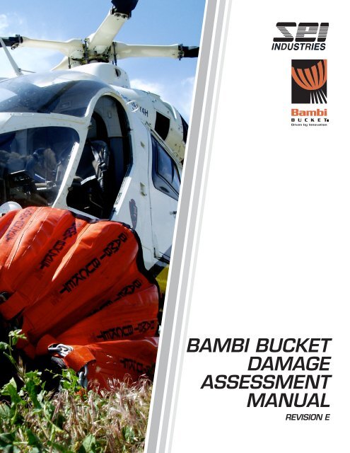
BAMBI BUCKET<br />
DAMAGE<br />
ASSESSMENT<br />
MANUAL<br />
REVISION E
Bambi Bucket<br />
RepairAssessment Manual<br />
Revision E<br />
Issue Date: June 2 2009<br />
®<br />
Manufacturedunderoneormoreofthe<br />
followingpatents:<br />
U.S. Patents 4,576,237 and 4,474,245<br />
Canada Patents 232,889 and 1,231,311<br />
U.K. Patent 2,145,624B<br />
<strong>SEI</strong>INDUSTRIESLTD.<br />
7400 WilsonAvenue<br />
Delta, BC, CANADA V4G 1E5<br />
Tel:(604)946-3131<br />
Fax:(604)940-9566<br />
E-Mail: seisales@sei-ind.com<br />
Web Site: www.sei-ind.com<br />
US & International Inquiries:<br />
<strong>SEI</strong> INTERNATIONALSALESINC.<br />
Suite #3, Beaumont House, Hastings,<br />
Christ Church, BARBADOS<br />
Tel:(246)228-4908<br />
Fax:(246)228-3326<br />
E-mail: <strong>bambi</strong>@sei-ind.com<br />
Web Site: www.sei-ind.com<br />
COPYRIGHT@2003<strong>SEI</strong>INDUSTRIESLTD. ALLRIGHTSRESERVED<br />
PRINTED IN CANADA<br />
1
TABLE OF CONTENTS<br />
Introduction 3<br />
Section A: Diagrams<br />
Shell and Valve models 6072 - 1821 4<br />
Shell and Valve models 2024 - HL9800 5<br />
IDS Hub 6<br />
Suspension Cables and M-Straps 7<br />
Section B: Carry Bag 8<br />
Repair Criteria Guidelines 9<br />
Section C: Shell<br />
Shell 10<br />
Top Webbing 11<br />
Bottom Webbing 12<br />
Bottom Loops 13<br />
Side Battens 15<br />
Top Loops 16<br />
Bambi Strips 17<br />
Ballast 18<br />
Repair Criteria Guidelines 19<br />
Section G: IDS System<br />
IDS System 40<br />
IDS Brackets 41<br />
IDS Hub Restrainer Cables 42<br />
IDS Hub 43<br />
IDS Spokes and Clevis Pins 45<br />
Repair Criteria Guidelines 46<br />
Section H: M-Straps and Top Chains<br />
M-Straps and Top Chains 47<br />
Repair Criteria Guidelines 48<br />
Section I: Control Head<br />
Trip Line 49<br />
Base Plate 51<br />
Wires 53<br />
Serial Number Plate 54<br />
Repair Criteria Guidelines 55<br />
Section J: General Inspection Criteria 56<br />
Section D: Cinch Straps 20<br />
Cinch Brackets 22<br />
Repair Criteria Guidelines 23<br />
Section E: Cables<br />
Cables 24<br />
Repair Criteria Guidelines 29<br />
Section F: Valve<br />
Valve Bolts 31<br />
Valve Body 32<br />
Valve Top Rubber 34<br />
Valve Bottom Rubber 35<br />
Purse Strings 36<br />
Restrainer Cables 38<br />
Repair Criteria Guidelines 39<br />
2
INTRODUCTION<br />
Introduction to the Bambi Bucket<br />
Since its introduction to the marketplace in 1983, the Bambi Bucket has become the preferred means of helicopter<br />
fire fighting by over 600 companies and agencies worldwide. The industrial fabrics used in the construction of the<br />
Bambi Bucket are designed specifically for the Bambi Bucket and meet substantial safety factors to provide the<br />
operator with a quality product that is designed to last.<br />
This <strong>manual</strong> is intended to provide the user with information that will allow for the proper repair<br />
<strong>assessment</strong> evaluation of the Bambi Bucket. The repair <strong>assessment</strong> process is mostly identical for all sizes of the<br />
Bambi Buckets, with exceptions noted for minor <strong>bucket</strong> design variations between the models. In these cases<br />
subsections describing the different types of <strong>damage</strong> will be presented. Diagrams, photos and part descriptions are<br />
provided as an aid for quick identification and evaluation of parts and components on the Bambi Bucket.<br />
This <strong>manual</strong> contains specific guidelines for the <strong>assessment</strong> of the operational condition of Bambi Buckets. At the<br />
end of each section of the Repair Assessment Manual is a guide that sorts the component defects into one of four<br />
categories, Safety, Operational, Monitor, and OKAY. Use the guideline definitions below to determine how<br />
urgently a repair should be carried out:<br />
Attached as a supplement is the repair <strong>assessment</strong> process and guidelines for the Bambi Bucket fitted with the<br />
PowerFill II shallow water pumping system. The following guidelines are also to be used to sort the component<br />
defects into categories and determine the urgency of repairs.<br />
Category 1: Safety<br />
All defects in this category must be repaired immediately before further operation of the Bambi Bucket. Ignoring<br />
defects in this category could result in personal injury or <strong>damage</strong> to equipment. These defects can compromise the<br />
following functions of the Bambi Bucket:<br />
1. Structural integrity<br />
2. Flight stability<br />
3. Water release<br />
4. Flight Safety<br />
Category 2: Operational<br />
All defects in this category should be repaired before the next operational day, or approximately 8 hours of<br />
flight time. The defects do not compromise the safety of the <strong>bucket</strong>, but may lead to Category 1 defects if<br />
not addressed within a short time frame.<br />
Category 3: Monitor<br />
Many defects such as wear, abrasion and minor impact <strong>damage</strong> do not need urgent attention. Defects of<br />
this nature should be monitored daily and repaired before the progress to Category 2 defect.<br />
Category 4: OKAY<br />
The Bambi Bucket does not need repairs.<br />
®<br />
3
SECTION A.: PARTS - SHELL AND VALVE MODELS 6072-1821<br />
Parts Diagram<br />
9<br />
5<br />
4<br />
11<br />
10<br />
15<br />
14<br />
16<br />
13 12<br />
Diagram #<br />
Description<br />
Diagram #<br />
Description<br />
1 Ballast Plates<br />
2 Dump Valve<br />
3 Cinch Strap<br />
4 IDS Hub<br />
5 IDS Spokes<br />
6 Purse Line Set<br />
7 Side Battens<br />
8 Bambi Bucket Shell<br />
9 Riser Ring<br />
10 IDS Brackets<br />
11 Top Webbing<br />
12 Bottom Webbing Loops<br />
13 Bottom Chain<br />
14 Hub Restrainer Bracket<br />
15 Cinch Strap Loop<br />
16 Bottom Webbing<br />
4<br />
Figure 1
SECTION A: PARTS - SHELL AND VALVE MODELS 2024-HL9800<br />
Parts Diagram<br />
13<br />
14<br />
10<br />
16<br />
15<br />
17<br />
11 12<br />
Diagram #<br />
Description<br />
Diagram #<br />
Description<br />
1 Ballast Plates<br />
2 Dump Valve<br />
3 Cinch Strap<br />
4 Cinch Strap Bar<br />
5 Riser Cable and Riser Ring<br />
6 Purse String Set<br />
7 Side Battens<br />
8 Bottom Webbing Loop Wear Strip<br />
9 Bambi Bucket Shell<br />
10 IDS Hub Spokes<br />
12 Bottom Chain<br />
11 Bottom Webbing Loops<br />
13 Valve Restrainer Cable<br />
14 IDS Hub<br />
15 IDS Brackets<br />
16 Top Webbing<br />
17 Bottom Webbing<br />
Figure 2<br />
5
SECTION A: PARTS - IDS HUB<br />
Parts Diagram<br />
7<br />
1<br />
6<br />
2<br />
3<br />
4 5<br />
Diagram #<br />
Description<br />
Diagram #<br />
Description<br />
1 IDS Hub<br />
2 IDS Hub Bracket<br />
3 Clevis Pin<br />
4 IDS Spokes<br />
5 IDS Hub Restrainer<br />
6 Swage Block<br />
7 Deployment cable<br />
6<br />
Figure 3
SECTION A: SUSPENSION CABLES AND M-STRAPS<br />
Parts Diagram<br />
5<br />
4<br />
1<br />
6<br />
2<br />
3<br />
Diagram #<br />
Description<br />
1 Suspension Cables<br />
2 Shackles<br />
3 M-Straps<br />
4 Valve Trip Line<br />
5 IDS Deployment Cable<br />
6 Top Chains<br />
Figure 4<br />
7
SECTION B: CARRY BAG<br />
Inspect the carry bag carefully. Look for any holes, broken zippers or torn handles. Torn handles and holes<br />
in bags can be fixed, but broken zippers cannot. The carry bag acts as a protective cover for the Bambi<br />
Bucket when not in use. In the event that the zipper is broken, you may want to replace the bag. Holes can<br />
be fixed by hand sewing fabric over the holes. Torn handles can be fixed by overlapping a portion of the handle<br />
webbing, and sewing it together.<br />
8
SECTION B: CARRY BAG<br />
Category 1: Safety<br />
Cease Operations and Repair Immediately<br />
• Not Applicable<br />
Category 2: Operational<br />
Repair before next days operation, or 8 hours flight time<br />
• Not Applicable<br />
Category 3: Monitor<br />
Monitor and or repair if condition deteriorates<br />
• Holes in the bag<br />
• Broken zipper<br />
• Torn handles<br />
Category 4: OKAY<br />
Does not need repair<br />
9
SECTION C: SHELL<br />
Bambi Bucket Shell<br />
The shell forms the basis for the Bambi Bucket. In your repair <strong>assessment</strong>, examine the shell for any weld<br />
separations along the panels, punctures, leaks or tears on the fabric, broken Top or Bottom<br />
Webbing Loops, broken Battens or for Bambi Strips that are beginning to peel away from the panel.<br />
• Small punctures, tears or leaks can be repaired by the operator, by welding a patch over the affected<br />
area with a heat gun (refer to Operator’s Manual for proper procedure). Large holes may require<br />
replacement of the panel.<br />
• Look for peeling along the welded seam. Examine the seams carefully by folding each panel along the weld’s<br />
edge, and look for any areas that have begun to peel. Sections that are peeling will appear to pull away from<br />
the mating panel when folded. If peeling is severe, the panel may need to be replaced<br />
In this picture, the operator applied a patch to cover a puncture<br />
Top Webbing<br />
Bambi Strips<br />
10
SECTION C: SHELL - TOP WEBBING<br />
Top Webbing<br />
The Top Webbing is sewn around the upper perimeter of the Bambi Bucket Shell. Its function is to reinforce the top<br />
of the Shell and to help prevent tears during operation. Examine the Top Webbing for broken stitching or tears. Pay<br />
close attention to the sewing directly below each Top Loop. Due to high tensile loading, broken stitching in this area<br />
may result in the Strip being pulled away from the Panel. Larger model <strong>bucket</strong>s have bolts as additional<br />
reinforcement to the stitching.<br />
Protective covers: used to protect the Top<br />
Loops from wear - on larger models only<br />
Top Webbing<br />
Top Chains<br />
Strip<br />
Examine the Top Webbing at the intersection<br />
of each Top Loop for broken stitching<br />
11
SECTION C: SHELL - BOTTOM WEBBING<br />
Bottom Webbing<br />
The webbing that is sewn to the bottom of the Bambi Bucket plays only a minor role in the structural<br />
integrity of the shell. The webbing’s primary purpose is to protect the ends of the panels from tearing or peeling<br />
apart. If the webbing is torn, or if some of the stitching has come loose it is recommended that repairs be carried out<br />
to prevent future <strong>damage</strong> to the <strong>bucket</strong> Shell.<br />
Valve Bolts<br />
Bottom Webbing - sewn to the bottom edge of the Bambi Bucket Shell<br />
12
SECTION C: SHELL - BOTTOM LOOPS<br />
Bottom Webbing Loops support the chain on the bottom of the <strong>bucket</strong>, which in turn helps to distribute the<br />
water load evenly among all the Panels of the <strong>bucket</strong>.<br />
Bottom chain<br />
Valve Bolts and Washers<br />
Bottom Webbing wear strips are used to protect<br />
the Bottom Webbing Loops from wear<br />
Bottom Webbing Loops<br />
13
SECTION C: SHELL - BOTTOM LOOPS<br />
Examine the Bottom Webbing Loops for any wear, tears and broken loops. The majority of the wear will occur<br />
where the loops make contact with the chain. Broken Bottom Loops may adversly affect the operation of the<br />
Valve.<br />
The protective Wear Strips are designed to protect the Bottom Webbing Loops from abrasive wear, and are not<br />
load bearing components. Worn or <strong>damage</strong>d wear strips can easily be replaced. Small amounts of broken stitching<br />
will not affect the function of a loop. Significant <strong>damage</strong> may require that the Loop be re-sewn.<br />
Note: Some older models of Bambi Buckets do not have the Wear Strips.<br />
Washers and bolts used to attach the<br />
Wear Strip<br />
valve to the <strong>bambi</strong> Bucket Shell<br />
Bottom Chain<br />
Bottom Webbing<br />
Wear Strip<br />
Stitching on the Load<br />
Bearing webbing loop<br />
Wear may be found in the corners of the loops<br />
where they make contact with the chain<br />
Bottom webbing loop<br />
14
SECTION C: SHELL - SIDE BATTENS<br />
Side Battens<br />
The Side Battens give the Bambi Bucket some shape when the <strong>bucket</strong> is empty. They assist in the process of<br />
deploying and filling the <strong>bucket</strong>. A minimum number of broken Battens will not affect the safe operation of the<br />
Bambi Bucket, but the sharp edges of broken Battens may cause small punctures through the shell with prolonged<br />
operation. Replacement of broken Battens is recommended.<br />
Operators who cinch their <strong>bucket</strong>s beyond the maximum cinch rating run the risk of breaking the Battens.<br />
Step 1<br />
To Check for broken battens:<br />
Open up the <strong>bucket</strong> and turn it upside down. For<br />
a large heavy <strong>bucket</strong>, lay the <strong>bucket</strong> onto its<br />
side.<br />
Step 2<br />
Place your hand along the centerline of the strip<br />
that you want to inspect, and grab the bottom of<br />
the <strong>bucket</strong> as shown in the picture.<br />
Step 3<br />
Using your other hand, apply pressure along the<br />
length of the strip, checking for breaks<br />
• Broken Battens will make a cracking<br />
noise<br />
• Broken Battens will bend at the<br />
break point<br />
15
SECTION C: SHELL - TOP LOOPS<br />
Examine the Top Loops for tears and wear under the knot.<br />
16
SECTION C: SHELL - BAMBI STRIPS<br />
Bambi Strips<br />
Look for cuts that run across the Strip. Cuts can be on the surface of the strip only, or they can penetrate through<br />
the Strip into the webbing. Cuts may also break through the stitching that holds the webbing to the Strip, and may<br />
result in the stitching in that area working loose over time. Small cuts can usually be repaired by applying a patch<br />
with a heat gun or with glue (see Operator’s Manual). If the cut is deep enough such that it severs the webbing, the<br />
panel may need replacement.<br />
The Strip may peel away from the Shell at the weld. Peeling can expose the scrim on the Panel, which could result<br />
in leaks or punctures.<br />
Webbing, which is sewn to the Bambi Strip is used to transfer<br />
the vertical loads to the Shell and the Bottom Chain. Look for<br />
torn loops, or broken or loose stitching.<br />
Battens are inserted between the Bambi Strip and<br />
the panel and help give the <strong>bucket</strong> its shape.<br />
Here, the Bambi Strip, which is welded to the<br />
Panel, has began to peel away.<br />
As long as the topcoat on the Panel is intact, up to 4<br />
inches of peeled weld is acceptable.<br />
17
SECTION C: SHELL - BALLAST<br />
Ballast<br />
All Bambi Buckets use ballast to assist in sinking the <strong>bucket</strong> when dipping and to help stabalize the <strong>bucket</strong> in flight.<br />
The Ballast comes in the form of steel Ballast Bars, or Ballast Bags filled with lead shot. The Ballast Bags are no<br />
longer offered with new <strong>bucket</strong>s, but can still be found on older models. Conversion kits are available for those<br />
who wish to convert from Ballast Bags to Ballast Bars.<br />
Ballast Bars: Examine the Shell for missing Bars, or missing retaining hardware. Check the Ballast backing plates,<br />
which are mounted behind the Ballast bars on the other side of the shell, for rough or bent edges. Rough edges may<br />
result in cutting on the Shell.<br />
Ballast Bags: Look for tears, and for broken tabs or missing grommets. If the Ballast bag needs repairs,<br />
Conversion to Ballast Bars is recommended.<br />
Steel Ballast Bars mounted to the outside of a<br />
Bambi Bucket.<br />
Ballast Bags (used on older models of the Bambi<br />
Bucket) are located on the inside of the shell.<br />
18
SECTION C: SHELL - REPAIR CRITERIA GUIDELINES<br />
Category 1: Safety<br />
Cease Operations and Repair Immediately<br />
• 1 or more broken Top Loop knots (M-Strap attachment point to the shell)<br />
• Gross punctures through shell that cut or severely <strong>damage</strong> one or more Panel Strips<br />
• Separation of fabric welds longer than 3” (76 mm)<br />
• Punctures or cuts through shell longer than 3” (76 mm)<br />
• 2 or more broken Bottom Webbing Loops<br />
Category 2: Operational<br />
Repair before next days operation, or 8 hours flight time<br />
• Top Loop knots that are worn or have <strong>damage</strong> to more than 25% of the fabric<br />
• Cuts, punctures or weld separations less than 3” and / or cut through more than 25% of a Panel<br />
Strip<br />
• Bottom Webbing Loops with more than 25% <strong>damage</strong> to fabric strands<br />
• Broken or missing Bottom Webbing protective wear strips<br />
• 5 or more broken Battens<br />
Category 3: Monitor<br />
Monitor and or repair if condition deteriorates<br />
• Wear, abrasions, and cuts to the Bucket Shell fabric isolated to one side of the material<br />
that do not cut through.<br />
• Wear, abrasions and cuts to the Webbing Loops, Strips, and Top Loop knots that involve less<br />
than 25% of the fabric strands on any portion of the affected webbing.<br />
• Wear and abrasions to Webbing Protective Strips<br />
• Up to 4” (102 mm) of peeled weld on Panel Strip<br />
• Up to 4 broken Battens<br />
Category 4: OKAY<br />
Does not need repair<br />
19
SECTION D: CINCH STRAPS<br />
Cinch Strap<br />
The Cinch Strap is located on the inside of the Bambi Bucket for models 8096 - 4453, and on the outside of the<br />
Bambi Bucket for models 5566 - HL9800. The Cinch Strap is made up of a strap, hook, and load-setting rings.<br />
Each ring location has a tag that indicates the percentage of maximum fill. Examine each strap for <strong>damage</strong> to the<br />
hook, torn or broken cinch straps and missing or broken rings at each load tag. A <strong>damage</strong>d cinch strap may impair<br />
the operator’s ability to reduce the maximum volume of the Bambi Bucket. Cinching beyond the marked load<br />
ratings may result in <strong>damage</strong> to the <strong>bucket</strong>. Tying knots in in the Cinch Strap is not an acceptable practice as it will<br />
give a false indication of the actual maximum volume of water in the <strong>bucket</strong>. Buckets that are operated in the<br />
cinched mode should have their Hub Restrainer Cables adjusted (see Operators Manual).<br />
The Cinch Strap hook may not work properly if the jaw is broken or if the latch has been <strong>damage</strong>d. Examine the<br />
hook carefully, and <strong>manual</strong>ly test the latch for correct operation. If it does not close or lock properly, the cinch<br />
strap needs to be replaced.<br />
Cinch Strap Hook for Bambi<br />
Models 2024 - HL9800<br />
Cinch Strap Hook for Bambi<br />
Models 8096 - 1821<br />
Manually test the latch for correct operation<br />
20
SECTION D: CINCH STRAPS<br />
When cinched, the strap is under tension. Any tears or cuts in the strap may eventually result in breakage.<br />
Beside the load rings on are tags indicating the percentage of maximum fill. Examine each ring and the<br />
stitching that holds the ring in place. Straps that show signs of loose or broken stitching at the load ring<br />
should be repaired or replaced.<br />
Load tag Cinch Strap Cinch bracket<br />
Rings<br />
21
SECTION D: CINCH BRACKETS<br />
Cinch Brackets<br />
The Cinch Brackets retain the Cinch Strap to the <strong>bucket</strong> Shell.<br />
There are two versions of the Cinch Brackets:<br />
• Fabric Cinch Brackets are found on the small Bambi Bucket (Models 8096 - 1821)<br />
• Aluminum Cinch Brackets are found on the meduim and large Bambi Buckets (Models 2024 - HL9800)<br />
Bucket models 8096 - 1821: The Cinch Bracket is made from fabric, and is sewn to the inside<br />
of the Bambi Bucket Shell. Look for tears and loose or broken stitching. Torn or broken Cinch Brackets<br />
must be replaced. The ability of the Cinch Strap to reduce the volume of water in the <strong>bucket</strong> will be<br />
compromised if any Brackets are non-funtional.<br />
Bucket models 2024 - 4453: The medium size Bambi Buckets use aluminum Cinch Brackets, which are<br />
located on the inside of the <strong>bucket</strong>’s shell. Examine the Brackets for any bending and look for broken or<br />
missing hardware. Broken bolts, bent Cinch Brackets or bent washers should be replaced. Loose bolts<br />
can be tightened.<br />
Bucket models 5566 - HL9800: The large <strong>bucket</strong>s have their Cinch Brackets located on theoutside of the<br />
Bambi Bucket Shell. Examine the Brackets for any bending, dents and rough edges. Look for broken or missing<br />
hardware. Broken bolts, bent Cinch Brackets or bent washers should be replaced. Loose bolts can be tightened.You<br />
may be able to file or sand the edges of the Cinch Brackets that have experienced some gouging.<br />
22
SECTIONS D: CINCH STRAP - REPAIR CRITERIA GUIDELINES<br />
The following guidelines apply to Bambi Buckets where the Cinch Strap is in use and is the only<br />
method of limiting the maximum gross capacity of the <strong>bucket</strong>.<br />
Category 1: Safety<br />
Cease operations and repair immediately<br />
• Broken or missing Cinch Strap<br />
• Field-modified Cinch Strap<br />
• Broken or missing Cinch Strap retaining brackets<br />
• Broken or missing Cinch Strap hook or mating ring<br />
Category 2: Operational<br />
Repair before next days operations, or 8 hours flight time<br />
• Wear or <strong>damage</strong> to Cinch Strap involving more than 25% of the fabric strands<br />
• Missing Cinch Strap bracket hardware.<br />
Category 3: Monitor<br />
Monitor and or repair if condition deteriorates<br />
• Wear or <strong>damage</strong> to Cinch Strap, less than 25%<br />
• Worn or bent brackets<br />
Category 4: OKAY<br />
Does not need repair<br />
23
SECTION E: CABLES<br />
The various cables on the Bambi Bucket use common components and examination of all cables is similar. Look<br />
for breaks, frayed wires, twisting and kinks. Pay close attention to the wires directly under the swage blocks as<br />
These areas may display more fatigue wear than on other parts of the cable.<br />
Suspension Lines<br />
The Suspension Lines interface the control head with the M-Straps and carry the load in the Bambi Bucket.<br />
Riser Cable<br />
The Riser Cable connects the trip Line to the Riser Ring.<br />
Hub Restrainer Cables<br />
The Hub Restrainer cables are connected from the Hub restrainer brackets, located on the inside bottom of<br />
the shell, to the IDS hub. They prevent the IDS hub from deploying beyond its designed position when the<br />
Bambi Bucket is empty.<br />
Deployment Cable.<br />
The Deployment Cable pulls vertically on the IDS hub when the <strong>bucket</strong> is lifted, and deploys the IDS hub<br />
system.<br />
Valve Restrainer Cable<br />
The valve Restrainer Cable prevents the valve from being pulled out of the Bambi Bucket when in<br />
operation.<br />
Tripline<br />
The Tripline connects to the Riser Cable on Bambi Bucket Models 6072 - 1821 (small <strong>bucket</strong>s). The Tripline is<br />
routed through a small pulley that attaches to the Riser Ring. The purpose of the Tripline is to retract and release the<br />
dump valve.<br />
24
SECTION E: CABLES<br />
Suspension Lines<br />
Swage Blocks<br />
Examine the cables directly under the Swage<br />
Blocks and look for any frayed or broken wires.<br />
Thimble<br />
Shackle<br />
25
SECTION E: CABLES<br />
In your repair <strong>assessment</strong>, you may encounter thimbles that are bent, twisted or have begun to stretch as shown in<br />
picture below. Some elongation of the Thimbles may occur in use. Elongation is acceptable as long as the cable is<br />
not <strong>damage</strong>d, and the Thimble is not cracked or broken.<br />
Swage Block<br />
A portion of the Thimble has been bent, and can be repaired quickly by<br />
pressing down to its original position with a pair of pliers<br />
Suspension Cable<br />
Bent or twisted Thimbles can easily be repaired by untwisting or<br />
bending the Thimble back to its original position with a pair of pliers.<br />
26
SECTION E: CABLES<br />
Frayed wires on the Riser cable or the IDS<br />
Restrainer cable can cause tears in the valve<br />
fabric.<br />
Twisted cables that show no signs of<br />
fraying, kinks, or broken strands can usually<br />
have their twist worked out. If the twisted<br />
cable cannot be reasonably straightened<br />
then the cable may need replacement.<br />
Cables that have broken must be replaced<br />
Cables that have severe kinks or broken wire<br />
bundles should to be replaced.<br />
27
SECTION E: CABLES<br />
Kinks that cause the wire bundles to spread<br />
apart are known as “Bird Caging”. If you can<br />
see through the strands, as shown in the picture,<br />
then thecable should be replaced.<br />
Bent cables that do not show signs of Bird<br />
Caging can usually have the kink worked out<br />
by hand.<br />
Protective covers are intended to protect the<br />
cable from wear. When protective covers have<br />
more than 25% wear on in a single wear area,<br />
or if they have broken in two or more pieces,<br />
they should be replaced.<br />
28
SECTION E: CABLES - REPAIR CRITERIA GUIDELINES<br />
Category 1: Safety<br />
Cease operations and repair immediately<br />
• 1 or more broken Suspension Cables or end fittings<br />
• Broken Riser cable<br />
• Broken Deployment Cable<br />
• Broken Tripline<br />
Category 2: Operational<br />
Repair before next days operations, or 8 hours flight time<br />
If 3 or more individual Suspension Cables, Riser Cables, or the Deployment cable have the<br />
following defects:<br />
• 10 or more randomly distributed broken strands, or 4 adjacent broken strands<br />
• Visible kink or kinks<br />
• Separation of the strands due to twisting (known as “Bird-Caging”)<br />
• Evidence of heat <strong>damage</strong><br />
• Abrasion wear comprising of more than 1/3 of the original diameter of the outside individual<br />
strands<br />
• Any visible reduction in outside diameter due to overload<br />
• Cracked or broken end fittings (some elongation of cable eyes is acceptable)<br />
Category 3: Monitor<br />
Monitor and or repair if condition deteriorates<br />
• Wear, broken strands, kinks and twisting in cable that do not exceed the limits defined in<br />
Category 2 defects<br />
Category 4: OKAY<br />
Does not need repair<br />
29
SECTION F: VALVE<br />
Purse strings<br />
Valve bolts - used to attach the<br />
valve to the shell<br />
Valve<br />
Grommets<br />
30
SECTION F: VALVE - VALVE BOLTS<br />
Inspection of the Valve<br />
There are three areas on the valve that are of primary interest when inspecting the valve:<br />
1) the Valve Bolts<br />
2) the Valve Body<br />
3) the Valve Rubber<br />
Valve Bolts<br />
The Valve bolts attach the Valve to the Shell and are located on the bottom of the <strong>bucket</strong>. Examine the Valve Bolts<br />
and look for any <strong>damage</strong>. Bent washers, broken or loose Valve Bolts may allow leakage. Replace all bent washers<br />
and broken bolts. Loose Valve Bolts can be tightened.<br />
Bottom Webbing<br />
Bottom Loops<br />
Rubber gasket used to prevent<br />
leakage through the bolt holes<br />
Washers and Bolts used to attach the<br />
valve to the Bambi Bucket Shell<br />
Bottom Chain<br />
31
SECTION F: VALVE - VALVE BODY<br />
Valve Body<br />
The Valve Body must be examined for <strong>damage</strong>. Look for any chafing, tearing of the valve fabric, missing<br />
grommets, fold marks, punctures in the fabric or errosion of the glue along the stitching.<br />
Neoprene rubber is sewn to the<br />
inside of the valve.<br />
The grommets are punched through the top collar (on older<br />
models, the grommets may be punched through the neoprene rubber)<br />
The Valve Body is closed<br />
along a single seam<br />
Bottom collar and grommets. Neoprene<br />
rubber is sewn to the bottom side of the<br />
collar<br />
Main Valve Body<br />
32
SECTION F: VALVE - VALVE BODY<br />
Chafing on the Valve Body may lead to wear spots that can weaken the material. Wear spots may tear or<br />
puncture easily and lead to leakage. If wear is substantial, replacement of the Valve may be required. Tears in the<br />
Valve can not be repaired.<br />
Examine the top part of the Valve, and look for displaced or missing grommets. The Purse Strings can cut through<br />
the Valve’s fabric if the Grommets are displaced, resulting in a leaking valve. Older style valves have grommets that<br />
are punched through the Valve Rubber. If the strings <strong>damage</strong> the rubber, the Valve should be replaced.<br />
Fold marks can cause the Valve’s topcoat to break away from the scrim, and may cause the Valve to tear. Fold<br />
marks can appear as the result of improper preparation for storage (See Operator’s Manual).<br />
Class A foam residue may cause some stiffness of the valve’s fabric if not thoroughly washed off before<br />
storage.<br />
Punctures in the valve’s fabric will result in leakage.<br />
Small punctures created during the stitching process are sealed to prevent leaks along the seams. Check all<br />
sewing on the Valve body, and look for broken stitching, and areas along the seams where the sealant may be<br />
peeling away. Broken stitching or peeling sealant may result in leaks.<br />
Examine all of the stitching on both the inside<br />
and outside of the valve. Look for any loose or<br />
broken stitching. Also examine the sealant on<br />
the stitching for peeling.<br />
Broken stitching may indicate that the seam has<br />
separated. Failure along the seam will result in<br />
leaks.<br />
New sealant that has been applied over the<br />
stitrching will appear clear in color. With use<br />
and age, it can become opaque (whiten). This<br />
can be an indication that the sealant has lost its<br />
adhesive properties.<br />
33
SECTION F: VALVE - TOP AND BOTTOM RUBBER<br />
Top Rubber<br />
The Top Rubber (made from neoprene rubber) is sewn to the inside top collor on the Valve. When the Bambi<br />
Bucket is filled with water, the pressure acting on the Valve forces the purse strings to tighten and pull the Top<br />
Rubber together, sealing the Valve.<br />
Examine the neoprene rubber for any tears, broken stitching, and check that the main seam is still glued<br />
together. If the seam or stitching comes apart, the valve will not seal properly.<br />
Top collar<br />
Check that the seam is properly glued, and that<br />
there are no signs separation.<br />
Grommets<br />
Check for broken<br />
or loose stitching<br />
An example of grommet<br />
holes that have<br />
been punched<br />
through the valve’s<br />
neoprene rubber<br />
(older model <strong>bucket</strong>s<br />
only)<br />
34
SECTION F: VALVE - BOTTOM RUBBER<br />
Bottom Rubber<br />
The Bottom Rubber is used to seal the bottom of the valve to the shell. After prolonged use, the rubber can<br />
become compressed, causing some of the bolts to loosen. This can be corrected by simply tightening the bolts.<br />
Valve Bottom Rubber<br />
Bolt holes are punched into the neoprene rubber<br />
35
SECTION F: VALVE - PURSE STRINGS<br />
Purse Strings<br />
The Purse Strings are ropes that pull the Valve into the closed position. Look for frayed or broken ropes, bent or<br />
broken washers or loose knots.<br />
Examine the Purse Strings for loose knots at both ends. Loose knots can be re-tied. Broken strings may result in<br />
leaks and should be replaced.<br />
Grommet with missing Purse String. The<br />
Valve will not seal properly in this area.<br />
The knot and washer at the end of the Purse String prevent it<br />
from pulling through the grommet hole.<br />
Broken purse string<br />
36
SECTION F: VALVE - PURSE STRINGS<br />
Look for fraying along the length of each Purse String. On the medium and large <strong>bucket</strong> models (2024 - HL9800),<br />
fraying will occur where the Purse String goes through the grommet hole on the Valve. On the small <strong>bucket</strong> models<br />
(8096 - 1821), Purse Strings also pass through the IDS hub, and some fraying may occur there as well.<br />
Wear on the Purse Strings occurs through normal operation of the Valve and should be<br />
monitored. Frayed strings may eventually break resulting in Valve leakage.<br />
Top collar<br />
Check the grommets for any rough edges or raised lips that may be<br />
accelerating the wearing process. These may have to be replaced if the are a problem.<br />
37
SECTION F: VALVE - VALVE RESTRAINER CABLES<br />
The Valve Restrainer Cables prevent excessive stress on the Valve when the water is released from the <strong>bucket</strong>.<br />
They are connected from the M-Straps to the Riser Ring. Wear may occur where the Restrainer Cables rub<br />
against the inside edge of the IDS Hub. Check the cable for frayed wired directly under the swage block, and<br />
for worn protective covers. Damage to the Restrainer Cable could cause <strong>damage</strong> to the valve through<br />
prolonged use.<br />
Valve Restrainer cables. Check the<br />
cable for any worn or Frayed wires.<br />
Riser Ring<br />
Valve Restrainer cables. Check for any<br />
frayed wires under the swage blocks.<br />
38
SECTION F: VALVE - REPAIR CRITERIA GUIDELINES<br />
Category 1: Safety<br />
Cease operations and repair immediately<br />
• Broken Valve Restrainer Cable<br />
• 5 or more broken purse strings<br />
Category 2: Operational<br />
Repair before the next days operation, or 8 hours flight time<br />
• Up to 4 broken Purse Strings<br />
• Wear or <strong>damage</strong> to the Purse Strings comprising more than 50% of fibers<br />
• Cuts or tears on valve material<br />
• Broken stitching that allows separation of seam(s)<br />
• Wear, abrasion and creases that allow leakage<br />
• Broken or missing Valve bolts<br />
• Missing or broken Purse Strings Grommets<br />
• Frayed wires on riser cable<br />
Category 3: Monitor<br />
Monitor and or repair if condition deteriorates<br />
• Wear and abrasion on valve material<br />
• Wear on Purse Strings<br />
• Valve bolt security<br />
Category 4: OKAY<br />
Does not need repair<br />
39
SECTION G: IDS SYSTEM<br />
The IDS Hub assembly consists of the IDS Hub, spokes, clevis pins, IDS brakets and cables. The IDS Hub is the<br />
attachment point for the Spokes.<br />
Look for chips, cracks, broken brackets, or enlarged bracket holes. Also look for frayed, twisted or kinked hub<br />
restrainer cables.<br />
Riser cable is attached to the Trip Line,<br />
which controls the operation of the valve<br />
Deployment Cable<br />
IDS Hub<br />
IDS Bracket<br />
IDS Hub Bracket is the attachment<br />
point for the IDS spokes<br />
Riser Ring<br />
Clevis Pins are used to fasten the<br />
IDS spokes to the Hub Brackets.<br />
IDS Spokes<br />
Valve Restrainer Cable<br />
40
SECTION G: IDS BRACKETS<br />
Examine the IDS Brackets for bending and enlargment of the clevis pin holes. Bent Brackets may bind against the<br />
Spoke, and prevent the <strong>bucket</strong> from deploying properly. If the clevis pin holes are too large, the pins can pull out.<br />
Check for loose bolts on the IDS Brackets. Loose IDS Brackets may pull through the fabric or <strong>damage</strong> the<br />
Battens.<br />
Check bolts for tightness<br />
IDS Spoke<br />
IDS Bracket<br />
Clevis Pin<br />
Bracket that has been bent<br />
Bracket with an enlarged hole<br />
41
SECTION G: IDS HUB RESTRAINER CABLES<br />
The IDS Hub Restrainer cables prevent the Hub from opening beyond its proper deployed position.<br />
Check the cables for frayed wires. Also check directly under the swage block for frayed wires.<br />
IDS Restrainer Cables<br />
42
SECTION G: IDS HUB<br />
The IDS Hub is the mounting point for all IDS spokes.<br />
Check for any cracks or broken parts. If any part of the Hub or Hub Brackets are cracked or broken, the hub<br />
needs to be replaced.<br />
Examine the IDS Hub for any cracks<br />
Examine the IDS Hub Brackets for any<br />
cracks or breaks.<br />
43
SECTION G: IDS SPOKES AND CLEVIS PINS<br />
Examine each Spoke and Clevis pin for bending. The Spoke should be replaced if it is bent or if the holes have<br />
enlarged to the point that the head of the Clevis pin can pass through freely. In the event of a heavy impact, the<br />
Spokes are designed to bend before the Shell is <strong>damage</strong>d.<br />
Bent Clevis pins must be replaced. In the event that the operator does not have access to Clevis pins, a correctly<br />
sized locknut and bolt can be used instead.<br />
Look for <strong>damage</strong> in these areas<br />
A lock nut and bolt can beused in place of a clevis pin.<br />
44
SECTION G: IDS SPOKES AND CLEVIS PINS<br />
Examine each Spoke for holes that have stretched through<br />
wear. If the hole is large enough such that the head of a<br />
Clevis pin can pass through, then the Spoke needs to be<br />
replaced.<br />
Examine each spoke for any broken holes. In this<br />
example, a piece of the spoke has broken away, and the<br />
spoke should be replaced.<br />
Bent or broken Spokes will affect the deployment of the<br />
<strong>bucket</strong>. In the event of an overload Spokes are designed<br />
to bend and will prevent <strong>damage</strong> the Shell.<br />
Clevis pins may bend on a hard impact. Bent Clevis pins<br />
should be replaced. A correctly sized bolt and a locking<br />
nut will act as a suitable replacement.<br />
45
SECTION G: IDS HUB - REAPIR CRITERIA GUIDELINES<br />
Category 1: Safety<br />
Cease operations and repair immediately<br />
• Cracks or breaks across the major section of the IDS hub<br />
• 2 or more broken or cracked Spoke Brackets<br />
• 2 or more broken or missing Spokes, Clevis Pins, Shell Brackets<br />
• 3 or more bent spokes (bends in excess of 20 degrees = broken)<br />
Category 2: Operational<br />
Repair before next days operation, or 8 hours of flight time<br />
• 1 broken or cracked Spoke Brackets on IDS Hub<br />
• 1 broken or missing Spoke<br />
• 1 broken or missing Clevis Pin or Shell Bracket<br />
• Up to 2 bent Spokes<br />
Category 3: Monitor<br />
Monitor and or repair if condition deteriorates<br />
• Wear on IDS hub<br />
• Dents, abrasions and wear on Spokes<br />
• Clevis Pin and Shell Bracket wear<br />
Category 4: OKAY<br />
Does not need repair<br />
46
SECTION H: M-STRAPS AND TOP CHAINS<br />
M-Straps<br />
The M-Straps are tied to the Top Loops on the <strong>bucket</strong> Shell. They transfer the loads between the Suspension<br />
Lines and the <strong>bucket</strong> Shell. Examine the M-Straps for broken webbing and fraying. Minor fraying can be mitigated<br />
by melting the frayed area with a flame.<br />
Top Chains<br />
Chains are used in place of the M-Straps on the weighted side of the <strong>bucket</strong> because of their greater durability and<br />
resistance to abrasion. The weighted side of the <strong>bucket</strong> is naturally subjected to more wear and tear in operation.<br />
Damage to the Chains is rare, but in the event that the Chain is broken, it must to be replaced.<br />
Chains are used because they can withstand<br />
abrasive wear on the weighted side of the<br />
<strong>bucket</strong><br />
M-Straps are used to transfer the vertical loads<br />
form the Suspension Lines to the Shell<br />
47
SECTION H: M-STRAPS AND TOP CHAINS REPAIR CRITERIA GUIDELINES<br />
Category 1: Safety<br />
Cease Operations and repair immediately<br />
• Broken Top Chains<br />
• Broken or missing Shackles<br />
• 2 or more broken M-Straps<br />
Category 2: Operational<br />
Repair before the next days operation, or 8 hours flight time<br />
• M-Straps with more than 25% of the fabric strands broken<br />
• Visibly worn Top Chains<br />
• Bent, gouged, worn, or cracked Shackles and Shackle pins<br />
Category 3: Monitor<br />
Monitor and or repair if condition deteriorates<br />
• Damage to an M-Strap that does not exceed 25% of the fabric<br />
• Minor wear, impact marks or corrosion on Chains<br />
• Minor wear, impact marks or corrosion on Shackles<br />
Category 4: OKAY<br />
Does not need repair<br />
48
SECTION I: CONTROL HEAD - TRIP LINE<br />
The Trip Line is connected from the Control head to the Riser Cable. The Trip Line controls the operation<br />
of the Valve.<br />
Examine the Trip Line for frays, kinks or loose swages.<br />
Examine the swage block for displacement from original position<br />
Examine the Trip Line directly under the swage block for any frayed wire.<br />
49
SECTION I: CONTROL HEAD - TRIP LINE<br />
Examine the section of the Trip Line line that enters that control head. Cycle the Trip Line in and out of the head<br />
several times to confirm that the Spring Reel and Trip mechanism are functioning correctly.<br />
Note: If the Cover is installed, use electrical power to operate the release solenoid.<br />
Spring Reel<br />
Catch<br />
Release the Catch on the Trip Block and pull down on the Trip Line. Inspect the top swage<br />
block and cable. Cycle the Trip Line a few times, checking that the spring reel and trip<br />
mechanism work correctly (refer to Operator’s Manual).<br />
50
SECTION I: CONTROL HEAD - BASE PLATE<br />
As well as being the main lifting member on the Bambi Bucket, the Control Head base plate serves as the mounting<br />
point for the Valve release mechanism.<br />
There can be no cracks, broken parts, or bends on the base plate. Some operators may attempt to<br />
repair heads by welding. This practice is not acceptable as it may weaken the casting material and lead<br />
to sudden failure.<br />
Examine the base plate for any broken parts such as broken<br />
Yokes, or broken Suspension Cable Mounts<br />
Welded repairs are unacceptable. The control head shown<br />
here must be removed from service and scrapped.<br />
Look for base plates that have been bent. Bending like this<br />
requires a lot of force, and can occur if the operator lands<br />
directly on the Head<br />
51
SECTION I: CONTROL HEAD - BASE PLATE<br />
Examine the Base plate for <strong>damage</strong>d Suspension Line<br />
mounts. If bent or twisted the control head must be<br />
replaced.<br />
Examine the base plate for any cracks. Remove the cover<br />
of the Control Head if a full inspection is required.<br />
Base plates that show signs of stretching or overloads<br />
at the shackle pin bosses must be replaced<br />
52
SECTION I: CONTROL HEAD - WIRES<br />
Examine the wire cover for wear, and for exposed conductors. Damage to the wiring may lead to a short that<br />
prevents the operator from being able to release the water load.<br />
Frayed covers or exposed wire must be replaced<br />
53
SECTION I: CONTROL HEAD - SERIAL NUMBER PLATE<br />
The serial number plate identifies the <strong>bucket</strong> model, serial number and gross capacity of the <strong>bucket</strong>.<br />
In the event the the plate is missing, or if it’s been <strong>damage</strong>d such that the information is no longer legible, a new plate<br />
is required.<br />
54
SECTION I: CONTROL HEAD - REPAIR CRITERIA GUIDELINES<br />
Category 1: Safety<br />
Cease operations and repair immediately<br />
• Any visible crack or break on the base plate<br />
• Visibly bent Shackles or Suspension Line bolts<br />
• Broken or missing safety wire on Shackle pins<br />
• Missing, broken, or loose Valve release mechanism parts<br />
• Broken or exposed electrical conductors<br />
• Broken or missing break-away plug<br />
• Broken or cracked Shackle yoke<br />
Category 2: Operational<br />
Repair before next days operations, or 8 hours flight time<br />
• Missing Control Head cover hardware<br />
• Cracked or <strong>damage</strong>d Control Head cover<br />
Category 3: Monitor<br />
Monitor and or repair if condition deteriorates<br />
• General wear and visual condition of components, including electrical connections and wire<br />
• Optimal function of Valve release mechanism, check daily<br />
Category 4: OKAY<br />
Does not need repair<br />
55
SECTION J: GENERAL INSPECTION CRITERIA<br />
Category 1 Defects<br />
• Excessive gross Bucket weight for specific helicopter and/or operating conditions<br />
(Ref. Section 16.1, Bambi Bucket Operator’s Manual)<br />
• Maximum total length of Bucket in excess of hook to tail rotor distance, minus 6 inches<br />
(Ref. Section 3.3, Bambi Bucket Operator’s Manual)<br />
56