Fiber Distributed Data Interface
Fiber Distributed Data Interface
Fiber Distributed Data Interface

Create successful ePaper yourself
Turn your PDF publications into a flip-book with our unique Google optimized e-Paper software.
CHAPTER<br />
8<br />
Chapter Goals<br />
• Provide background information about FDDI technology.<br />
• Explain how FDDI works.<br />
• Describe the differences between FDDI and Copper <strong>Distributed</strong> <strong>Data</strong><br />
<strong>Interface</strong> (CDDI).<br />
• Describe how CDDI works.<br />
<strong>Fiber</strong> <strong>Distributed</strong> <strong>Data</strong> <strong>Interface</strong><br />
Introduction<br />
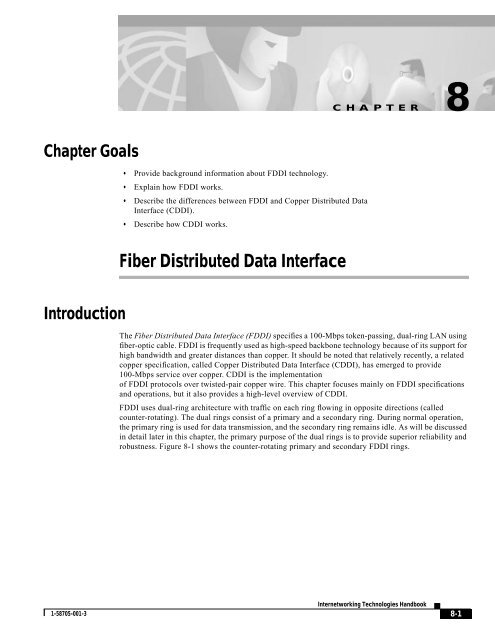
The <strong>Fiber</strong> <strong>Distributed</strong> <strong>Data</strong> <strong>Interface</strong> (FDDI) specifies a 100-Mbps token-passing, dual-ring LAN using<br />
fiber-optic cable. FDDI is frequently used as high-speed backbone technology because of its support for<br />
high bandwidth and greater distances than copper. It should be noted that relatively recently, a related<br />
copper specification, called Copper <strong>Distributed</strong> <strong>Data</strong> <strong>Interface</strong> (CDDI), has emerged to provide<br />
100-Mbps service over copper. CDDI is the implementation<br />
of FDDI protocols over twisted-pair copper wire. This chapter focuses mainly on FDDI specifications<br />
and operations, but it also provides a high-level overview of CDDI.<br />
FDDI uses dual-ring architecture with traffic on each ring flowing in opposite directions (called<br />
counter-rotating). The dual rings consist of a primary and a secondary ring. During normal operation,<br />
the primary ring is used for data transmission, and the secondary ring remains idle. As will be discussed<br />
in detail later in this chapter, the primary purpose of the dual rings is to provide superior reliability and<br />
robustness. Figure 8-1 shows the counter-rotating primary and secondary FDDI rings.<br />
1-58705-001-3<br />
Internetworking Technologies Handbook<br />
8-1
FDDI Transmission Media<br />
Chapter 8<br />
<strong>Fiber</strong> <strong>Distributed</strong> <strong>Data</strong> <strong>Interface</strong><br />
Figure 8-1<br />
FDDI Uses Counter-Rotating Primary and Secondary Rings<br />
Standards<br />
FDDI was developed by the American National Standards Institute (ANSI) X3T9.5 standards committee<br />
in the mid-1980s. At the time, high-speed engineering workstations were beginning to tax the bandwidth<br />
of existing local-area networks (LANs) based on Ethernet and Token Ring. A new LAN media was<br />
needed that could easily support these workstations and their new distributed applications. At the same<br />
time, network reliability had become an increasingly important issue as system managers migrated<br />
mission-critical applications from large computers to networks. FDDI was developed to fill these needs.<br />
After completing the FDDI specification, ANSI submitted FDDI to the International Organization for<br />
Standardization (ISO), which created an international version of FDDI that is completely compatible<br />
with the ANSI standard version.<br />
FDDI Transmission Media<br />
FDDI uses optical fiber as the primary transmission medium, but it also can run over copper cabling. As<br />
mentioned earlier, FDDI over copper is referred to as Copper-<strong>Distributed</strong> <strong>Data</strong> <strong>Interface</strong> (CDDI).<br />
Optical fiber has several advantages over copper media. In particular, security, reliability, and<br />
performance all are enhanced with optical fiber media because fiber does not emit electrical signals. A<br />
physical medium that does emit electrical signals (copper) can be tapped and therefore would permit<br />
unauthorized access to the data that is transiting the medium. In addition, fiber is immune to electrical<br />
interference from radio frequency interference (RFI) and electromagnetic interference (EMI). <strong>Fiber</strong><br />
historically has supported much higher bandwidth (throughput potential) than copper, although recent<br />
technological advances have made copper capable of transmitting at 100 Mbps. Finally, FDDI allows 2<br />
km between stations using multimode fiber, and even longer distances using a single mode.<br />
FDDI defines two types of optical fiber: single-mode and multimode. A mode is a ray of light that enters<br />
the fiber at a particular angle. Multimode fiber uses LED as the light-generating device, while<br />
single-mode fiber generally uses lasers.<br />
8-2<br />
Internetworking Technologies Handbook<br />
1-58705-001-3
Chapter 8<br />
<strong>Fiber</strong> <strong>Distributed</strong> <strong>Data</strong> <strong>Interface</strong><br />
FDDI Specifications<br />
Multimode fiber allows multiple modes of light to propagate through the fiber. Because these modes of<br />
light enter the fiber at different angles, they will arrive at the end of the fiber at different times. This<br />
characteristic is known as modal dispersion. Modal dispersion limits the bandwidth and distances that<br />
can be accomplished using multimode fibers. For this reason, multimode fiber is generally used for<br />
connectivity within a building or a relatively geographically contained environment.<br />
Single-mode fiber allows only one mode of light to propagate through the fiber. Because only a single<br />
mode of light is used, modal dispersion is not present with single-mode fiber. Therefore, single-mode<br />
fiber is capable of delivering considerably higher performance connectivity over much larger distances,<br />
which is why it generally is used for connectivity between buildings and within environments that are<br />
more geographically dispersed.<br />
Figure 8-2 depicts single-mode fiber using a laser light source and multimode fiber using a light emitting<br />
diode (LED) light source.<br />
Figure 8-2<br />
Light Sources Differ for Single-Mode and Multimode <strong>Fiber</strong>s<br />
FDDI Specifications<br />
FDDI specifies the physical and media-access portions of the OSI reference model. FDDI is not actually<br />
a single specification, but it is a collection of four separate specifications, each with a specific function.<br />
Combined, these specifications have the capability to provide high-speed connectivity between<br />
upper-layer protocols such as TCP/IP and IPX, and media such as fiber-optic cabling.<br />
FDDI’s four specifications are the Media Access Control (MAC), Physical Layer<br />
Protocol (PHY), Physical-Medium Dependent (PMD), and Station Management (SMT) specifications.<br />
The MAC specification defines how the medium is accessed, including frame format, token handling,<br />
addressing, algorithms for calculating cyclic redundancy check (CRC) value, and error-recovery<br />
mechanisms. The PHY specification defines data encoding/decoding procedures, clocking requirements,<br />
and framing, among other functions. The PMD specification defines the characteristics of the<br />
transmission medium, including fiber-optic links, power levels, bit-error rates, optical components, and<br />
connectors. The SMT specification defines FDDI station configuration, ring configuration, and ring<br />
control features, including station insertion and removal, initialization, fault isolation and recovery,<br />
scheduling, and statistics collection.<br />
FDDI is similar to IEEE 802.3 Ethernet and IEEE 802.5 Token Ring in its relationship with the OSI<br />
model. Its primary purpose is to provide connectivity between upper OSI layers of common protocols<br />
and the media used to connect network devices. Figure 8-3 illustrates the four FDDI specifications and<br />
their relationship to each other and to the IEEE-defined Logical Link Control (LLC) sublayer. The LLC<br />
sublayer is a component of Layer 2, the MAC layer, of the OSI reference model.<br />
1-58705-001-3<br />
Internetworking Technologies Handbook<br />
8-3
FDDI Station-Attachment Types<br />
Chapter 8<br />
<strong>Fiber</strong> <strong>Distributed</strong> <strong>Data</strong> <strong>Interface</strong><br />
Figure 8-3<br />
FDDI Specifications Map to the OSI Hierarchical Model<br />
FDDI Station-Attachment Types<br />
One of the unique characteristics of FDDI is that multiple ways actually exist by which to connect FDDI<br />
devices. FDDI defines four types of devices: single-attachment station (SAS), dual-attachment station<br />
(DAS), single-attached concentrator (SAC), and dual-attached concentrator (DAC).<br />
An SAS attaches to only one ring (the primary) through a concentrator. One of the primary advantages<br />
of connecting devices with SAS attachments is that the devices will not have any effect on the FDDI ring<br />
if they are disconnected or powered off. Concentrators will be covered in more detail in the following<br />
discussion.<br />
Each FDDI DAS has two ports, designated A and B. These ports connect the DAS to the dual FDDI ring.<br />
Therefore, each port provides a connection for both the primary and the secondary rings. As you will see<br />
in the next section, devices using DAS connections will affect the rings if they are disconnected or<br />
powered off. Figure 8-4 shows FDDI DAS A and B ports with attachments to the primary and secondary<br />
rings.<br />
8-4<br />
Internetworking Technologies Handbook<br />
1-58705-001-3
Chapter 8<br />
<strong>Fiber</strong> <strong>Distributed</strong> <strong>Data</strong> <strong>Interface</strong><br />
FDDI Fault Tolerance<br />
Figure 8-4<br />
FDDI DAS Ports Attach to the Primary and Secondary Rings<br />
An FDDI concentrator (also called a dual-attachment concentrator [DAC]) is the building block of an<br />
FDDI network. It attaches directly to both the primary and secondary rings and ensures that the failure<br />
or power-down of any SAS does not bring down the ring. This is particularly useful when PCs, or similar<br />
devices that are frequently powered on and off, connect to the ring. Figure 8-5 shows the ring<br />
attachments of an FDDI SAS, DAS, and concentrator.<br />
Figure 8-5<br />
A Concentrator Attaches to Both the Primary and Secondary Rings<br />
FDDI Fault Tolerance<br />
FDDI provides a number of fault-tolerant features. In particular, FDDI’s dual-ring environment, the<br />
implementation of the optical bypass switch, and dual-homing support make FDDI a resilient media<br />
technology.<br />
1-58705-001-3<br />
Internetworking Technologies Handbook<br />
8-5
FDDI Fault Tolerance<br />
Chapter 8<br />
<strong>Fiber</strong> <strong>Distributed</strong> <strong>Data</strong> <strong>Interface</strong><br />
Dual Ring<br />
FDDI’s primary fault-tolerant feature is the dual ring. If a station on the dual ring fails or is powered<br />
down, or if the cable is damaged, the dual ring is automatically wrapped (doubled back onto itself) into<br />
a single ring. When the ring is wrapped, the dual-ring topology becomes a single-ring topology. <strong>Data</strong><br />
continues to be transmitted on the FDDI ring without performance impact during the wrap condition.<br />
Figure 8-6 and Figure 8-7 illustrate the effect of a ring wrapping in FDDI.<br />
8-6<br />
Internetworking Technologies Handbook<br />
1-58705-001-3
Chapter 8<br />
<strong>Fiber</strong> <strong>Distributed</strong> <strong>Data</strong> <strong>Interface</strong><br />
FDDI Fault Tolerance<br />
Figure 8-6<br />
A Ring Recovers from a Station Failure by Wrapping<br />
Station 1<br />
MAC<br />
B<br />
A<br />
Station 4<br />
Ring wrap<br />
Ring wrap<br />
Station 2<br />
A<br />
B<br />
MAC<br />
B<br />
A<br />
MAC<br />
A<br />
B<br />
Failed station<br />
Station 3<br />
1-58705-001-3<br />
Internetworking Technologies Handbook<br />
8-7
FDDI Fault Tolerance<br />
Chapter 8<br />
<strong>Fiber</strong> <strong>Distributed</strong> <strong>Data</strong> <strong>Interface</strong><br />
Figure 8-7<br />
A Ring also Wraps to Withstand a Cable Failure<br />
When a single station fails, as shown in Figure 8-6, devices on either side of the failed (or<br />
powered-down) station wrap, forming a single ring. Network operation continues for the remaining<br />
stations on the ring. When a cable failure occurs, as shown in Figure 8-7, devices on either side of the<br />
cable fault wrap. Network operation continues for all stations.<br />
It should be noted that FDDI truly provides fault tolerance against a single failure only. When two or<br />
more failures occur, the FDDI ring segments into two or more independent rings that are incapable of<br />
communicating with each other.<br />
Optical Bypass Switch<br />
An optical bypass switch provides continuous dual-ring operation if a device on the dual ring fails. This<br />
is used both to prevent ring segmentation and to eliminate failed stations from the ring. The optical<br />
bypass switch performs this function using optical mirrors that pass light from the ring directly to the<br />
DAS device during normal operation. If a failure of the DAS device occurs, such as a power-off, the<br />
optical bypass switch will pass the light through itself by using internal mirrors and thereby will<br />
maintain the ring’s integrity.<br />
The benefit of this capability is that the ring will not enter a wrapped condition in case of a device failure.<br />
Figure 8-8 shows the functionality of an optical bypass switch in an FDDI network. When using the OB,<br />
you will notice a tremendous digression of your network as the packets are sent through the OB unit.<br />
8-8<br />
Internetworking Technologies Handbook<br />
1-58705-001-3
Chapter 8<br />
<strong>Fiber</strong> <strong>Distributed</strong> <strong>Data</strong> <strong>Interface</strong><br />
FDDI Fault Tolerance<br />
Figure 8-8<br />
The Optical Bypass Switch Uses Internal Mirrors to Maintain a Network<br />
Station 1<br />
Station 1<br />
Failed station<br />
B<br />
A<br />
A<br />
B<br />
Optical bypass switch<br />
“normal configuration”<br />
Optical bypass switch<br />
“bypassed configuration”<br />
Ring does not wrap<br />
Station 4<br />
Station 2<br />
Station 4<br />
Station 2<br />
A<br />
A<br />
A<br />
A<br />
B<br />
B<br />
B<br />
B<br />
A<br />
B<br />
A<br />
B<br />
Station 3<br />
Station 3<br />
Dual Homing<br />
Critical devices, such as routers or mainframe hosts, can use a fault-tolerant technique called dual<br />
homing to provide additional redundancy and to help guarantee operation. In dual-homing situations, the<br />
critical device is attached to two concentrators. Figure 8-9 shows a dual-homed configuration for devices<br />
such as file servers and routers.<br />
1-58705-001-3<br />
Internetworking Technologies Handbook<br />
8-9
FDDI Frame Format<br />
Chapter 8<br />
<strong>Fiber</strong> <strong>Distributed</strong> <strong>Data</strong> <strong>Interface</strong><br />
Figure 8-9<br />
A Dual-Homed Configuration Guarantees Operation<br />
Concentrator<br />
Concentrator<br />
File servers<br />
Routers<br />
ct840809<br />
One pair of concentrator links is declared the active link; the other pair is declared passive. The passive<br />
link stays in backup mode until the primary link (or the concentrator to which it is attached) is<br />
determined to have failed. When this occurs, the passive link automatically activates.<br />
FDDI Frame Format<br />
The FDDI frame format is similar to the format of a Token Ring frame. This is one of the areas in which<br />
FDDI borrows heavily from earlier LAN technologies, such as Token Ring. FDDI frames can be as large<br />
as 4,500 bytes. Figure 8-10 shows the frame format of an FDDI data frame and token.<br />
Figure 8-10<br />
The FDDI Frame Is Similar to That of a Token Ring Frame<br />
FDDI Frame Fields<br />
The following descriptions summarize the FDDI data frame and token fields illustrated in Figure 8-10.<br />
8-10<br />
Internetworking Technologies Handbook<br />
1-58705-001-3
Chapter 8<br />
<strong>Fiber</strong> <strong>Distributed</strong> <strong>Data</strong> <strong>Interface</strong><br />
Copper <strong>Distributed</strong> <strong>Data</strong> <strong>Interface</strong><br />
• Preamble—Gives a unique sequence that prepares each station for an upcoming frame.<br />
• Start delimiter—Indicates the beginning of a frame by employing a signaling pattern that<br />
differentiates it from the rest of the frame.<br />
• Frame control—Indicates the size of the address fields and whether the frame contains<br />
asynchronous or synchronous data, among other control information.<br />
• Destination address—Contains a unicast (singular), multicast (group), or broadcast (every station)<br />
address. As with Ethernet and Token Ring addresses, FDDI destination addresses are 6 bytes long.<br />
• Source address—Identifies the single station that sent the frame. As with Ethernet and Token Ring<br />
addresses, FDDI source addresses are 6 bytes long.<br />
• <strong>Data</strong>—Contains either information destined for an upper-layer protocol or control information.<br />
• Frame check sequence (FCS)—Is filed by the source station with a calculated cyclic redundancy<br />
check value dependent on frame contents (as with Token Ring and Ethernet). The destination<br />
address recalculates the value to determine whether the frame was damaged in transit. If so, the<br />
frame is discarded.<br />
• End delimiter—Contains unique symbols; cannot be data symbols that indicate the end of the<br />
frame.<br />
• Frame status—Allows the source station to determine whether an error occurred; identifies whether<br />
the frame was recognized and copied by a receiving station.<br />
Copper <strong>Distributed</strong> <strong>Data</strong> <strong>Interface</strong><br />
Copper <strong>Distributed</strong> <strong>Data</strong> <strong>Interface</strong> (CDDI) is the implementation of FDDI protocols over twisted-pair<br />
copper wire. Like FDDI, CDDI provides data rates of 100 Mbps and uses dual-ring architecture to<br />
provide redundancy. CDDI supports distances of about 100 meters from desktop to concentrator.<br />
CDDI is defined by the ANSI X3T9.5 Committee. The CDDI standard is officially named the<br />
Twisted-Pair Physical Medium-Dependent (TP-PMD) standard. It is also referred to as the Twisted-Pair<br />
<strong>Distributed</strong> <strong>Data</strong> <strong>Interface</strong> (TP-DDI), consistent with the term <strong>Fiber</strong> <strong>Distributed</strong> <strong>Data</strong> <strong>Interface</strong> (FDDI).<br />
CDDI is consistent with the physical and media-access control layers defined by the ANSI standard.<br />
The ANSI standard recognizes only two types of cables for CDDI: shielded twisted pair (STP) and<br />
unshielded twisted pair (UTP). STP cabling has 150-ohm impedance and adheres to EIA/TIA 568 (IBM<br />
Type 1) specifications. UTP is data-grade cabling (Category 5) consisting of four unshielded pairs using<br />
tight-pair twists and specially developed insulating polymers in plastic jackets adhering to EIA/TIA<br />
568B specifications.<br />
Figure 8-11 illustrates the CDDI TP-PMD specification in relation to the remaining FDDI specifications.<br />
1-58705-001-3<br />
Internetworking Technologies Handbook<br />
8-11
Summary<br />
Chapter 8<br />
<strong>Fiber</strong> <strong>Distributed</strong> <strong>Data</strong> <strong>Interface</strong><br />
Figure 8-11<br />
CDDI TP-PMD and FDDI Specifications Adhere to Different Standards<br />
Summary<br />
The <strong>Fiber</strong> <strong>Distributed</strong> <strong>Data</strong> <strong>Interface</strong> (FDDI) specifies a 100-Mbps token-passing, dual-ring LAN<br />
architecture using fiber-optic cable. FDDI is frequently implemented as a high-speed backbone<br />
technology because of its support for high bandwidth and greater distances than copper.<br />
Review Questions<br />
Q—What are the benefits of using FDDI instead of CDDI?<br />
A—Longer distance, no RFI, no EFI.<br />
Q—What role does the DAC play in the FDDI network?<br />
A—The concentrator is a dual-attachment station device and ensures that when single-attachment station<br />
devices—such as PCs—are turned off, they do not interrupt the network ring.<br />
8-12<br />
Internetworking Technologies Handbook<br />
1-58705-001-3