HOTLink™ Copper Interconnect— Maximum Length vs. Frequency
HOTLink™ Copper Interconnect— Maximum Length vs. Frequency
HOTLink™ Copper Interconnect— Maximum Length vs. Frequency

Create successful ePaper yourself
Turn your PDF publications into a flip-book with our unique Google optimized e-Paper software.
fax id: 5105<br />
HOTLink <strong>Copper</strong> <strong>Interconnect—</strong><br />
<strong>Maximum</strong> <strong>Length</strong> <strong>vs</strong>. <strong>Frequency</strong><br />
Introduction<br />
The most common question asked about any serial interface<br />
is, “How long of a link can I have?” The answer comes down<br />
to a mixture of transmission line characteristics, and the jitter<br />
generation and tolerance of the serial data transmitter and<br />
receiver.<br />
While the jitter characteristics of both the CY7B923 and<br />
CY7B933 HOTLink Transmitter and Receiver are very stable<br />
across frequency, temperature, and voltage, such is not<br />
the case for copper cables. The signal distortion introduced<br />
by these cables is very non-linear with respect to distance<br />
and frequency. In addition, there are large variations in these<br />
non-linear characteristics based on the specific type of cable<br />
selected.<br />
Cable Testing<br />
To determine just how these cable characteristics affect data<br />
transmission, a number of tests were performed to determine<br />
the maximum data-rate versus distance characteristics of a<br />
number of common cable types. These tests were performed<br />
using multiple CY9266–T and CY9266–C HOTLink Evaluation<br />
Boards, and nine different types of copper cable.<br />
Equipment<br />
The following equipment was used for the cable evaluations:<br />
• HP8116A pulse/function generator<br />
• Three CY9266–C HOTLink Evaluation Boards for testing<br />
coaxial cable<br />
• Four CY9266–T HOTLink Evaluation Boards for testing<br />
twisted-pair cable<br />
• Multiple segments of each cable type, capable of being<br />
combined to length multiples of 50 feet<br />
The specific cable types evaluated are not meant to be inclusive<br />
of all possible cable types that may be used with HOT-<br />
Link. Instead they were selected to represent a relatively wide<br />
range of commonly available cable types that are often used<br />
for communications or networking. The cables evaluated are<br />
listed in Table 1.<br />
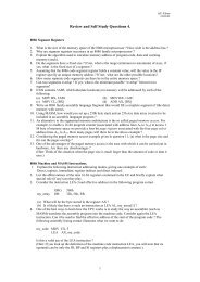
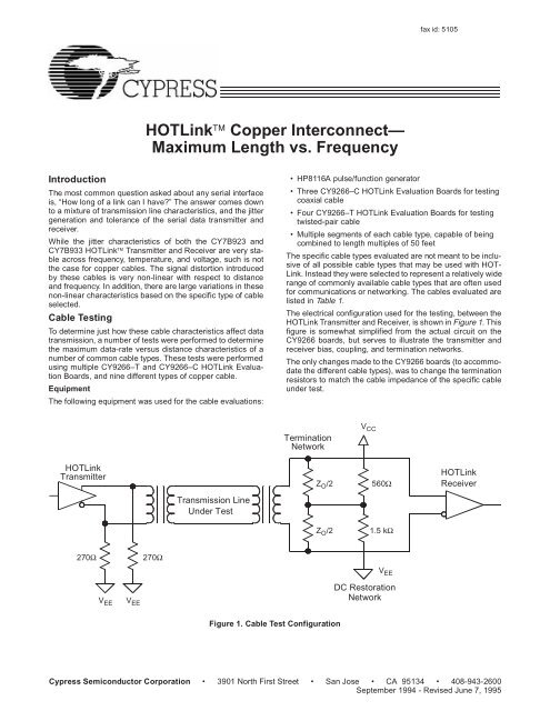
The electrical configuration used for the testing, between the<br />
HOTLink Transmitter and Receiver, is shown in Figure 1. This<br />
figure is somewhat simplified from the actual circuit on the<br />
CY9266 boards, but serves to illustrate the transmitter and<br />
receiver bias, coupling, and termination networks.<br />
The only changes made to the CY9266 boards (to accommodate<br />
the different cable types), was to change the termination<br />
resistors to match the cable impedance of the specific cable<br />
under test.<br />
Termination<br />
Network<br />
V CC<br />
HOTLink<br />
Transmitter<br />
Z O /2<br />
560Ω<br />
HOTLink<br />
Receiver<br />
Transmission Line<br />
Under Test<br />
Z O /2<br />
1.5 kΩ<br />
270Ω<br />
270Ω<br />
V EE V EE<br />
Network<br />
V EE<br />
DC Restoration<br />
Figure 1. Cable Test Configuration<br />
Cypress Semiconductor Corporation • 3901 North First Street • San Jose • CA 95134 • 408-943-2600<br />
September 1994 - Revised June 7, 1995
HOTLink—<strong>Maximum</strong> <strong>Length</strong> <strong>vs</strong>. <strong>Frequency</strong><br />
Table 1. Tested Cable Types<br />
Cable Type Mfgr. Model Type Z O<br />
Coax Belden 8219 RG58 50Ω<br />
Coax Belden 9259 RG59 75Ω<br />
Coax Belden 8255 RG62 93Ω<br />
Coax Belden 9066 RG6 75Ω<br />
Coax Belden 8218 75Ω<br />
Coax Belden 83264 RG179 75Ω<br />
Shielded Belden 9688 IBM ® 150Ω<br />
twisted pair<br />
Type-1<br />
Twisted pair Comtran PCC– UTP-3 100Ω<br />
FT4<br />
Twisted pair Comtran PCC–<br />
FT6<br />
UTP-5 100Ω<br />
Test Procedure<br />
The testing consisted of using the built-in self-test (BIST) capability<br />
of the HOTLink Transmitter and Receiver to determine<br />
where the link was usable (error free) and where errors<br />
started to occur. An external frequency source was applied to<br />
both the transmitter and receiver and adjusted (both up and<br />
down) in frequency while monitoring the BIST error display for<br />
any link errors.<br />
The criteria selected for an error-free link was that no errors<br />
be detected for a period of 20 minutes at a specific operating<br />
frequency and distance. This allows a large number of bits to<br />
be sent and received, and allows the HOTLink Transmitter<br />
and Receiver to stabilize at an operating temperature.<br />
It is understood that this period of time does not guarantee an<br />
error-free link forever. Any link, no matter how good, will still<br />
have some error rate characteristic associated with it. However,<br />
observations of these copper based links (made in the<br />
process of these tests) has shown that if a link runs error free<br />
for this 20-minute period of time, it will remain so for a much<br />
longer period (i.e., multiple days).<br />
Test Results<br />
RG58—50Ω Coaxial Cable<br />
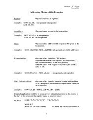
The first system tested used the 50Ω RG58 coaxial cable.<br />
This cable is commonly used in the Ethernet physical variant<br />
known as 10BASE2 or ThinNet. The test results for this cable<br />
are plotted in Figure 2.<br />
Of the three cards used in the testing, one used coupling<br />
transformers that had approximately twice the inductance of<br />
the other two. For this specific cable type (and for all other<br />
coaxial cables tested with this card) the maximum error free<br />
lengths at a specific operating frequency were always shorter<br />
than the equivalent lengths on the cards with low inductance<br />
transformers.<br />
55<br />
50<br />
45<br />
40<br />
35<br />
30<br />
25<br />
20<br />
15<br />
lower datasheet<br />
limit —160 Mbaud<br />
upper datasheet<br />
limit —330 Mbaud<br />
266 Mbaud<br />
10<br />
50 150 250 350 450 550 650<br />
Cable <strong>Length</strong> in Feet<br />
+ = low-inductance card 1<br />
= low-inductance card 2<br />
× = high-inductance card<br />
Figure 2. RG58 Test Results, Linear <strong>Frequency</strong> Scale<br />
Two reasons exist for this difference in operational length.<br />
First is based on the high-frequency bandwidth of the transformers.<br />
The high-inductance transformer (per the manufacturer’s<br />
data) has a high end –3 dB bandwidth of around 250<br />
MHz. Around this frequency point in the transformer, significant<br />
attenuation and phase shifts occur in the transmitted signal.<br />
Since it is these upper frequencies that provide a reasonable<br />
shape to the signal, their attenuation and distortion in the<br />
transformer causes less of these signal components to be<br />
available at the receiver.<br />
The second effect is caused by the low-frequency bandwidth<br />
of the transformer. The higher the transformer inductance, the<br />
better its low-frequency response. Unfortunately it is the<br />
low-frequency content of the transmitted signal that induces<br />
most of the data-dependent jitter (DDJ) in the serial link.<br />
In Figure 2, the frequency scale shows the clock rate delivered<br />
to the HOTLink Transmitter and Receiver. This clock rate<br />
is the byte rate for the transmitter and receiver. Because of<br />
the 8B10B encoding used to send serial information, the actual<br />
bit-rate on the serial interfaces is ten times this rate (i.e.,<br />
25 MHz=250 Mbits/second).<br />
This figure shows that with an RG58-type cable (having the<br />
same attenuation characteristics of the cable tested here),<br />
that it is possible to reliably transmit information at all distances<br />
HOTLink—<strong>Maximum</strong> <strong>Length</strong> <strong>vs</strong>. <strong>Frequency</strong><br />
components to either the source or destination ends of the<br />
cable it is possible to greatly extend the error-free link lengths.<br />
All test data presented in this application note is only for uncompensated<br />
links.<br />
RG59—75Ω Coaxial Cable<br />
RG59 is a 75Ω coaxial cable manufactured in a similar size<br />
and construction to RG58. The main difference between them<br />
is the ratio of inner to outer diameters that determine the characteristic<br />
impedance of the cable. When tested to the same<br />
criteria as the RG58 cable (as shown in Figure 3), numerous<br />
differences in operation become apparent.<br />
The most obvious difference is that the operable lengths have<br />
increased significantly: as much as 50% at 330 Mbits/second<br />
and 37% at 160 Mbits/second. In addition there is now a flat<br />
portion at the top end of the operating frequency range where<br />
changing the cable length has no effect on the maximum data-rate.<br />
At this top-end frequency the interconnect system still modifies<br />
or distorts the transmitted signal. However, the amount of<br />
distortion is small enough that a different factor is limiting the<br />
maximum operable distance of the link. At this frequency, the<br />
phase-locked loops (PLLs) in the transmitter and receiver are<br />
up against their maximum operable limit. Because the received<br />
signal characteristics remain within the minimum acceptable<br />
limits of the receiver through the 150-foot distance,<br />
the line remains flat.<br />
Beyond the 150-foot length the received signal is distorted<br />
enough such that the operating frequency must be reduced<br />
in order to bring the signal back to where the receiver can<br />
accurately capture it.<br />
55<br />
By taking the same data in Figure 3 and plotting it on a logarithmic<br />
frequency scale in Figure 4, another characteristic becomes<br />
visible. Now the curves for data-rate versus distance<br />
appear as a straight line. This means that this is actually an<br />
exponential function.<br />
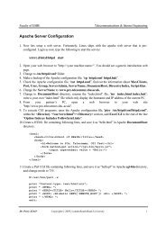
Other Cable Types<br />
Data-rate versus distance information was taken for all the<br />
cable types listed in Table 1. By plotting a composite chart of<br />
all these cable types, it is possible to see how the different<br />
cable characteristics affect the maximum operable length.<br />
This information is shown in Figure 5.<br />
RG62—93Ω Coaxial Cable<br />
RG62 is a 93Ω version of RG59 cable. It is made by removing<br />
some of the dielectric in the RG59 cable and replacing it with<br />
air, lowering the dielectric constant. Since the cable impedance<br />
is based on the dielectric constant of the spacer (in addition<br />
to the dimensions of the conductors), lowering the dielectric<br />
constant raises the impedance to 93Ω.<br />
Comparing the operable length characteristics of this cable<br />
with that of the RG58 and RG59 cables shows that the higher<br />
impedance RG62 again improves the maximum usable distance<br />
at all frequencies.<br />
50<br />
40<br />
30<br />
266 Mbaud<br />
upper datasheet<br />
limit —330 Mbaud<br />
50<br />
45<br />
40<br />
20<br />
lower datasheet<br />
limit —160 Mbaud<br />
35<br />
30<br />
25<br />
20<br />
15<br />
266 Mbaud<br />
lower datasheet<br />
limit —160 Mbaud<br />
10<br />
50 150 250 350 450 550 650<br />
Cable <strong>Length</strong> in Feet<br />
+ = low-inductance card 1<br />
= low-inductance card 2<br />
× = high-inductance card<br />
upper datasheet<br />
limit —330 Mbaud<br />
10<br />
50 150 250 350 450 550 650<br />
+ = low-inductance card 1<br />
= low-inductancecard 2<br />
× = high-inductance card<br />
Cable <strong>Length</strong> in Feet<br />
Figure 4. RG59 Test Results, Log <strong>Frequency</strong> Scale<br />
Figure 3. RG59 Test Results, Linear <strong>Frequency</strong> Scale<br />
3
HOTLink—<strong>Maximum</strong> <strong>Length</strong> <strong>vs</strong>. <strong>Frequency</strong><br />
50<br />
40<br />
30<br />
upper datasheet limit —330 Mbaud<br />
266 Mbaud<br />
20<br />
RG62<br />
194.4 Mbaud<br />
UTP3<br />
UTP5<br />
RG58<br />
RG179<br />
8218<br />
RG59<br />
STP1<br />
lower datasheet<br />
limit —160 Mbaud<br />
10<br />
0 50 100 150 200 250 300 350 400 450 500 550 600 650 700 750 800 850 900 950 1000<br />
Cable <strong>Length</strong> in Feet<br />
Figure 5. <strong>Maximum</strong> Data-Rate versus Distance Comparison<br />
RG6—75Ω Coaxial Cable<br />
RG6 is a 75Ω coaxial cable commonly used for CATV applications.<br />
While this cable does have the same impedance as<br />
the RG59 cable, its construction is quite different, as are its<br />
data transmission characteristics. This cable has larger inner<br />
and outer diameters for the conductors used in the cable.<br />
While the ratios of these diameters do maintain a 75Ω system,<br />
the increased dimensions create larger surface areas for<br />
the conductors and therefore lower losses.<br />
When compared to the RG59 cable, RG6 allows operable<br />
distances of nearly twice as far. At the low end (160<br />
Mbits/second) of the HOTLink operating range, this approaches<br />
1000 feet.<br />
RG179 and Belden 8218—75Ω Coaxial Cable<br />
The RG179 and Belden 8218 cables are also 75Ω types.<br />
These cables, however, are designed for different environments<br />
where signal loss is not the primary concern. The 8218<br />
cable type is a miniature form of RG59. With the smaller diameters<br />
(and smaller surface area) its losses at all frequencies<br />
are greater than those of RG59.<br />
RG179 is a cable designed both for tight spaces and harsh<br />
environments. Its Teflon® jacket allows it to be used where<br />
most cables cannot. If it was manufactured using the same<br />
materials as RG59 or 8218 cable, its losses would be much<br />
higher than they currently are. To limit the losses, the inner<br />
copper conductor is plated with silver to improve the<br />
skin-depth for high-frequency signals.<br />
Twisted-Pair Cables<br />
The other family of cables supported by HOTLink are known<br />
as twisted-pair cables. These cables were tested with the<br />
CY9266–T HOTLink boards.<br />
IBM Type-1—150Ω Shielded Twisted-Pair Cable<br />
The IBM Type-1 cable (STP1) consists of two individually<br />
shielded twisted pairs in a single cable. The cable itself was<br />
designed for token-ring network applications operating at 4 or<br />
16 Mbits/second. These network speeds are much less than<br />
those supported by HOTLink. Due to the excellent signal generation<br />
and handling characteristics of the HOTLink components,<br />
this same cable is usable over even greater distances<br />
at more than ten times its designed data rate.<br />
This cable has similar distance characteristics over frequency<br />
to the RG59 coaxial cable. Because two signal pairs are<br />
present in the same cable, a bidirectional link can be built<br />
using a single cable.<br />
Note: Other coupling mechanisms exist that permit bidirectional<br />
signal transmission on a single set of conductors. The<br />
theory and implementation of these specialized structures is<br />
beyond the scope of this document.<br />
Mechanically different forms of this cable exist with slightly<br />
modified signal characteristics. These variants (Type-2,<br />
Type-6, etc.) add extra non-data conductors or uses stranded-conductor<br />
construction to improve flexibility. If the variant<br />
selected has similar attenuation characteristics to Type-1, it<br />
should operate with a similar data-rate versus distance curve.<br />
UTP3 and UTP5—100Ω Unshielded Twisted Pair<br />
UTP3 and UTP5 are unshielded twisted-pair cables, most<br />
commonly used for 10BASE-T Ethernet or telephone installations.<br />
UTP3 (also known as category 3) is rated for Ethernet<br />
use at 10 Mbits/second at distances up to 100 meters (329<br />
feet), while UTP5 is rated at 100 Mbits/second at the same<br />
distance. In these unshielded cables (unlike STP1 or the coaxial<br />
cables), crosstalk becomes a significant link-limiting factor.<br />
4
HOTLink—<strong>Maximum</strong> <strong>Length</strong> <strong>vs</strong>. <strong>Frequency</strong><br />
Crosstalk occurs because of the close proximity of the two<br />
signal pairs. With no shield to keep their respective signals<br />
separated, the cable itself becomes both a long coupling<br />
transformer and coupling capacitor. This crosstalk combines<br />
with the attenuation characteristic of the cable to distort the<br />
signals on the cable.<br />
These unshielded cables will work fine for short- to medium-length<br />
interconnections when used with HOTLink. However,<br />
the lack of a cable shield may limit their use to environments<br />
where radiated emissions are not a concern; i.e.,<br />
inside a shielded cabinet or other enclosure.<br />
General Observations<br />
• Lower inductance transformers allow greater operating<br />
distance due to wider bandwidth.<br />
• Higher impedance cables have lower losses and allow<br />
greater operating distance.<br />
• Larger diameter cables have less attenuation and allow<br />
greater operating distance.<br />
Eye Pattern Testing<br />
While measurement of errors in a link does yield a significant<br />
amount of information about link operation, it does not explain<br />
the actual failure mechanism; i.e., why a signal is received in<br />
error. To do this requires looking at the actual signal. The<br />
following eye patterns and oscilloscope diagrams are used to<br />
explain the signal failure mode. All measurements are made<br />
with error free links based on RG59 cable.<br />
Figure 6 shows the wide-open eye at the source end of a link<br />
for both a normally driven and a source terminated (series<br />
resistance added to the driver, equal to the cable impedance)<br />
system. The eye has minimal distortion in both systems, but<br />
the added source resistance reduces the source signal amplitude<br />
by 6 dB for the source terminated link. These links<br />
both operate error free at 173 Mbits/second with 550 feet of<br />
cable attached.<br />
The same two systems are shown in Figure 7 at the receiver<br />
end of 550 feet of cable. Things look a bit different here. Now<br />
the eye is almost completely closed. The width of the opening<br />
in both configurations is approximately 500 ps. The only significant<br />
difference between the two links is that the source<br />
terminated signal has a smaller noise margin.<br />
To view the effect on high data-rate signals, two new links<br />
were configured at 363 Mbits/second with 300 feet of cable.<br />
At this data rate the bit-cell time is approximately half that of<br />
the pervious configuration. The source-signal eye diagrams<br />
for these systems are shown in Figure 8. Again, at the source<br />
end of the cable the signals are clean. While the edges appear<br />
to have somewhat slower ramp rates, this is due to the<br />
change in sweep frequency for the oscilloscope from 1 ns/division<br />
to 500 ps/division.<br />
Figure 9 shows the signals at the receiving end of the 300-foot<br />
cable. These signals look similar to the 550-foot link. The<br />
overall amplitude is somewhat larger, due to the lower attenuation<br />
of the shorter cable, but the eye is still almost completely<br />
closed. At this faster data rate, the minimum eye opening<br />
is again approximately 500 ps.<br />
The fact that the minimum eye opening of approximately<br />
500 ps remains the same at both data-rates is not just a coincidence.<br />
This number is based on the jitter tolerance and<br />
static alignment characteristics of the HOTLink receiver PLL<br />
and data-capture circuits.<br />
Timebase = 1.00 ns/div<br />
Normal Signal<br />
Ch. 1 = 200.0 mV/div<br />
Timebase = 1.00 ns/div<br />
Ch. 1 = 200.0 mV/div<br />
Source Terminated Signal<br />
Figure 6. Error-Free, 173-Mbit/second Signal at the Driver End of a 550-Foot RG59 Cable<br />
5
HOTLink—<strong>Maximum</strong> <strong>Length</strong> <strong>vs</strong>. <strong>Frequency</strong><br />
Timebase = 500 ps/div<br />
Normal Signal<br />
Ch. 1 = 100.0 mV/div<br />
Timebase = 500 ps/div<br />
Ch. 1 = 100.0 mV/div<br />
Source Terminated Signal<br />
Figure 7. Error-Free, 173-Mbit/second Signal at the Receiver End of a 550-Foot RG59 Cable<br />
Linear Time View<br />
The minimum-eye handling capability is a fixed characteristic<br />
of the HOTLink receiver. Changing the source-signal amplitude<br />
or data rate has no significant effect on this characteristic.<br />
But this still does not explain why the eye closes in the first<br />
place. To see this, it is necessary to look at how individual bits<br />
interact with each other.<br />
To see bit interaction on an oscilloscope it is necessary to<br />
change from a random data pattern (like the BIST pattern that<br />
was used for the previous tests), to a fixed pattern. To show<br />
the worst-case bit interaction it is also necessary to use a data<br />
pattern that contains the maximum and minimum run-lengths<br />
of 1s and 0s. Fortunately, a pattern meeting these characteristics<br />
is automatically generated by the HOTLink Transmitter<br />
when both ENA and ENN are disabled. The character sent<br />
under these conditions is known as a K28.5 code, which (following<br />
the 8B/10B disparity rules) generates a repeating<br />
20-bit pattern of 00111110101100000101.<br />
Timebase = 500 ps/div<br />
Normal Signal<br />
Ch. 1 = 200.0 mV/div<br />
Timebase = 500 ps/div<br />
Ch. 1 = 200.0 mV/div<br />
Source Terminated Signal<br />
Figure 8. Error-Free, 363-Mbit/second Signal at the Receiver End of a 300-Foot RG59 Cable<br />
6
HOTLink—<strong>Maximum</strong> <strong>Length</strong> <strong>vs</strong>. <strong>Frequency</strong><br />
Timebase = 1.00 ns/div Ch. 1 = 100.0 mV/div Timebase = 1.00 ns/div Ch. 1 = 100.0 mV/div<br />
Normal Signal<br />
Source Terminated Signal<br />
Figure 9. Error-Free, 363-Mbit/second Signal at the Receiver End of a 300-Foot RG59 Cable<br />
This pattern, when viewed at the end of the cable under the<br />
same data-rate and cable lengths of the previous two tests,<br />
is shown in Figure 10. The highlighted areas in each configuration<br />
show the bits that interact to cause the eye to close.<br />
In both configurations, two of these bits (at this worst-case<br />
data-rate) barely cross the receiver threshold. The long 1s<br />
and 0s immediately preceding them cause the signal to move<br />
the farthest from the receiver threshold.<br />
0 1 1 1 1 1 0 1 0 1 1 0 0 0 0 0 1 0 1 1 1 1 1 0 1 0 1 1 0 0 0 0 0 1 0<br />
Timebase = 10.0 ns/div<br />
Ch. 1 = 100.0 mV/div Timebase = 5.00 ns/div<br />
Ch. 1 = 100.0 mV/div<br />
173–Mbits/second @ 550 Feet 363–Mbits/second @ 550 300 Feet<br />
Figure 10. Error-Free, K28.5 Character at <strong>Maximum</strong> Data Rate<br />
7
HOTLink—<strong>Maximum</strong> <strong>Length</strong> <strong>vs</strong>. <strong>Frequency</strong><br />
The K28.5 character will always generate a signal that looks<br />
approximately the same at the maximum length limit of an<br />
uncompensated link. This is due both to the physics of the<br />
transmission line, and to the exceptional jitter tolerance of the<br />
HOTLink Receiver. The addition of an equalizer would level<br />
out the transitions and keep them centered around the receiver<br />
threshold.<br />
General Observations<br />
• Signal amplitude is not the length-limiting factor for most<br />
links.<br />
• The HOTLink Receiver’s jitter sensitivity window is approximately<br />
500 ps in size.<br />
• Equalization will allow much longer links.<br />
— HOTLink Receiver only requires 50 mV of signal.<br />
— Equalization may allow link lengths of four times that of<br />
a non-equalized link.<br />
Conclusion<br />
The CY7B922 and CY7B933 HOTLink data communications<br />
components can be used in communications links with almost<br />
any configuration of copper media. In these links the frequency<br />
attenuation characteristics of the copper media are the<br />
primary length limiting factors for a link. The enhanced sensitivity<br />
of the HOTLink receiver allows usage of forms of signal<br />
equalization that allow operation over much greater distances<br />
than non-equalized links.<br />
HOTLink is a trademark of Cypress Semiconductor Corporation.<br />
IBM is a registred trademark of International Business Machines, Inc.<br />
Teflon is a registered trademark of DuPont.<br />
© Cypress Semiconductor Corporation, 1995. The information contained herein is subject to change without notice. Cypress Semiconductor Corporation assumes no responsibility for the use<br />
of any circuitry other than circuitry embodied in a Cypress Semiconductor product. Nor does it convey or imply any license under patent or other rights. Cypress Semiconductor does not authorize<br />
its products for use as critical components in life-support systems where a malfunction or failure may reasonably be expected to result in significant injury to the user. The inclusion of Cypress<br />
Semiconductor products in life-support systems application implies that the manufacturer assumes all risk of such use and in doing so indemnifies Cypress Semiconductor against all charges.