

10.5 PREHEATING
API ICP Self Study Notes
API ICP Self Study Notes

You also want an ePaper? Increase the reach of your titles
YUMPU automatically turns print PDFs into web optimized ePapers that Google loves.
<strong>10.5</strong> <strong>PREHEATING</strong>
Preheating
Preheating
Preheating
Preheating
Preheating, for our purposes, is defined as heating of the weld and<br />
surrounding base metal to a predetermined temperature prior to the start of<br />
welding. The primary purpose for preheating carbon and low-alloy steels is to<br />
reduce the tendency for hydrogen induced delayed cracking. It does this by<br />
slowing the cooling rate, which helps prevent the formation of martensite in<br />
the weld and base metal HAZ. However, preheating may be performed for<br />
many reasons, including:
• Bring temperature up to preheat or interpass temperatures required by the<br />
WPS.<br />
• Reduce shrinkage stresses in the weld and base metal, which is especially<br />
important in weld joints with high restraint.<br />
• Reduce the cooling rate to prevent hardening and a reduction in ductility of<br />
the weld and base metal HAZ.<br />
• Maintain weld interpass temperatures.<br />
• Eliminate moisture from the weld area.<br />
• Meet the requirements of the applicable fabrication code, such as the<br />
ASME Boiler and Pressure Vessel Code, depending on the chemistry and<br />
thickness of the alloy to be welded.
If preheat is specified in the WPS it is important that the inspector confirms<br />
that the required temperature is maintained. This can be done using several<br />
methods, including (1) thermocouples, (2) contact pyrometer, (3) infrared<br />
temperature measuring instruments, or (4) temperature indicating crayons.<br />
The inspector should also remember that if preheat is required during welding<br />
the same preheat should be applied during tack welding, arc gouging and<br />
thermal cutting of the metal, all of which induce temperature changes similar<br />
to welding of the joint.
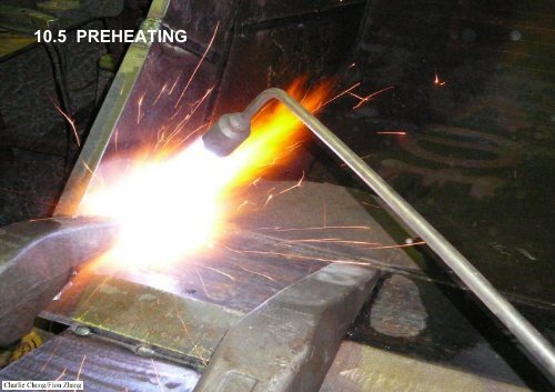
Preheat can be applied using several different techniques, but the most<br />
common techniques used in pipe and tank fabrication are electrical resistance<br />
coils, or an oxy-acetylene or natural gas torch. Good practice is to uniformly<br />
heat an area on either side of the weld joint for a distance three times the<br />
width of the weld. Preheat should be applied and extend to at least 2 in. (50.8<br />
mm) on either side of the weld to encompass the weld and potential heat<br />
affected zone areas. Inspectors shall exercise caution when welding metals<br />
of different chemistries or preheat requirements ensuring that preheats for<br />
both metals are in accordance with codes and the WPS documentation.<br />
Typically, the metal with the highest preheat requirement governs.
10.6 POST-WELD HEAT TREATMENT<br />
Post-weld heat treatment (PWHT) produces both mechanical and<br />
metallurgical effects in carbon and low-alloy steels that will vary widely<br />
depending on the composition of the steel, its past thermal history, the<br />
temperature and duration of the PWHT and heating and cooling rates<br />
employed during the PWHT. The need for PWHT is dependent on many<br />
factors ncluding;<br />
• chemistry of the metal,<br />
• thickness of the parts being joined,<br />
• joint design,<br />
• welding processes and<br />
• service or process conditions.
The temperature of PWHT is selected by considering the changes being<br />
sought in the equipment or structure. For example, a simple stress relief to<br />
reduce residual stresses will be performed at a lower temperature than a<br />
normalizing heat treatment. The holding time at temperature should also be<br />
selected to allow the desired time at temperature dependent actions to take<br />
place. In some isolated cases holding time and temperature are<br />
interchangeable, but small temperature changes have been shown to be<br />
equivalent to large changes in holding times.
The primary reason for post-weld heat treatment is to relieve the residual<br />
stresses in a welded fabrication. Stresses occur during welding due to the<br />
localized heating and severe temperature changes that occur. PWHT<br />
releases these stresses by allowing the metal to creep slightly at the elevated<br />
temperature.<br />
However there may also be in-service conditions that require particular<br />
PWHT conditions. These may not be so closely detailed in construction<br />
specifications and inspectors should therefore be particularly aware of these<br />
potential requirements when allowing, authorizing or inspecting in-service<br />
repairs.
Discussion:<br />
However there may also be in-service conditions that require particular<br />
PWHT conditions. These may not be so closely detailed in construction<br />
specifications and inspectors should therefore be particularly aware of<br />
these potential requirements when allowing, authorizing or inspecting<br />
in-service repairs.
PWHT (stress relief) can be applied by electrical resistance heating, furnace<br />
heating, or if allowed by the code, local flame heating. Temperatures should<br />
be monitored and recorded by thermocouples attached to the part being<br />
heated. Multiple thermocouples are often necessary to ensure proper PWHT<br />
of all components. Adequate support should be provided during any postweld<br />
heat treatment to prevent the sagging that could occur during the heat<br />
treatment.
Typical PWHT Chart<br />
Insertion<br />
temperature<br />
Free air cooling<br />
temperature
Typical PWHT Chart
PWHT Chart
PWHT- Typical PWHT Chart
PWHT
PWHT
PWHT
PWHT
PWHT
PWHT
PWHT
PWHT
PWHT
PWHT
PWHT
PWHT
PWHT- Local
PWHT- Local
PWHT- Local
PWHT- Local
PWHT- Local
PWHT- Local
PWHT- Local
PWHT- Local
PWHT- Equipments
PWHT- Equipments
PWHT- Equipments
PWHT- Equipments
PWHT- Equipments
PWHT- Equipments
PWHT- Equipments
PWHT- Equipments
Fun-Photo:<br />
Induction Bending<br />
Pipe bending with heat<br />
induction-Post Bending<br />
PWHT may be required
Fun-Photo:<br />
Induction Bending<br />
Pipe bending with heat<br />
induction-Post Bending<br />
PWHT may be required
Fun-Photo:<br />
Induction Bending<br />
Pipe bending with heat<br />
induction-Post Bending<br />
PWHT may be required<br />
Induction Bending<br />
http://www.youtube.com/watch?v=rO0idGX2gY4
10.7 HARDENING<br />
Hardening or hardenability is defined as that property of a ferrous alloy that<br />
determines the depth and distribution of hardness induced by quenching.<br />
• It is important to note that there is no close relation between hardenability<br />
and hardness, which is the resistance to indentation.<br />
Hardness depends primarily on the carbon content of the material, where as<br />
hardenability is strongly affected by the presence of alloying elements, such<br />
as chromium, molybdenum and vanadium, and to a lesser extent by carbon<br />
content and alloying elements such as nickel, copper and silicon.<br />
For example at standard medium carbon steel, such as AISI 1040 with no<br />
alloying elements has a lower hardenability then AISI 4340 low-alloy steel<br />
which has the same amount of carbon, but contains small amounts of<br />
chromium, nickel, molybdenum and silicon as alloying elements.
Other factors can also affect hardenability to a lesser extent than chemical<br />
composition; these include;<br />
• grain structure,<br />
• alloy homogeneity,<br />
• amount of certain microstructural phases present in the steel and<br />
• overall micro cleanliness of the steel.
AISI 1040 / 4340<br />
http://www.azom.com/article.aspx?ArticleID=6525
http://www.azom.com/article.aspx?ArticleID=6772
AISI 4340<br />
http://www.efunda.com/materials/alloys/alloy_steels/show_alloy.cfm?ID=AISI_4130&prop=all&Page_Title=AISI%204130
Welding variables, such as heat input, interpass temperature and size of the<br />
weld bead being applied all affect the cooling rate of the base metal HAZ<br />
which in turn affect the amount of martensite formation and hardness. The<br />
cooling rate of the base metal can also be affected by the section size of the<br />
base metal being welded, temperature of the metal eing welded and weld<br />
joint geometry. If the alloying elements which increase hardenability are found<br />
in the base metal HAZ, the cooling rate during welding necessary to produce<br />
a high hardness HAZ are generally lower than for plain carbon steel without<br />
alloying elements.<br />
Welding factors affecting Hardness;<br />
1. Heat input<br />
2. Preheat<br />
3. Interpass temperature<br />
4. Section sizes<br />
5. Weld joint geometry
Welding- Thick plate welding
Welding- Plate thickness & Weld Geometry
Thick plate welding
Weld Macro- Geometry
Weld Macro- Geometry
Weld Macro- Geometry
Weld Macro- Geometry
Weld Macro- Geometry
Weld Macro- Geometry
The simplest means to determine hardenability is to measure the depth to<br />
which a piece of steel hardens during quenching from an elevated<br />
temperature. There are several standardized tests for determining<br />
hardenability. A typical test of hardenability is called a Jominy Bar. In this test,<br />
a round bar is heated to a pre-determined elevated temperature until heated<br />
evenly through the cross section. The specimen then subjected to rapid<br />
quenching by spraying water against the bottom end of the round bar. The<br />
hardness of the test specimen is measured as a function of distance away<br />
from the surface being quenched. Steels that obtain high hardness well<br />
away from the quenched surface are considered to have high hardenability.<br />
Conversely, steels that do not harden well away from the quenched surface<br />
are considered to have low hardenability.
Jominy Bar
Jominy Bar
Jominy Bar
Jominy Bar
Jominy Bar
It may be important for the welding engineer and inspector to understand the<br />
hardenability of the steel as it can be an indirect indicator of weldability.<br />
Hardenability relates to the amount of martensite that forms during the<br />
heating and cooling cycles of welding. This is most evident in the base metal<br />
heat affected zone. Significant amounts of martensite formation in the HAZ<br />
can lead to delayed hydrogen cracking or a loss in ductility and toughness.<br />
Certain steels with high hardenability will form when they are cooled in air.<br />
While other steels with low hardenability require much faster cooling rates for<br />
form martensite. Knowing the hardenability will help the engineer or inspector<br />
determine if pre-heat or postweld heat treatment are required or if a controlled<br />
cooling practice may be acceptable to produce a serviceable weld and<br />
acceptable properties in the HAZ.<br />
Key Note: Hardenability affects weldability due to martensite formations at<br />
weld/HAZ which leads to HIC, loss of ductility and toughness.
Hardening of the weld and base metal HAZ are important because of<br />
hydrogen assisted cracking that occurs in carbon and low-alloy steels. As the<br />
hardness of the base metal HAZ increases so does the susceptibility to<br />
hydrogen assisted cracking. The hardness limits currently recommended for<br />
steels in refinery process service are listed in Table 11. Hardness values<br />
obtained in excess of these usually indicate that post-weld heat treatment is<br />
necessary, regardless of whether specified on the welding procedure<br />
specification. In those instances where PWHT is needed, an alternate<br />
welding procedure qualified with PWHT is necessary.<br />
Hardness in excess of those listed can result in stress corrosion cracking in<br />
service due to the presence of sulfides in the process. The 200 BHN limit for<br />
carbon steel is equally as important in sulfur containing oils as is the limit for<br />
Cr-Mo steels.
Typical Hardness Values<br />
Table 11—Brinell Hardness Limits for Steels in Refining Services
HIC- Hydrogen Induced Cracking
HIC
HIC- Hydrogen Induced Cracking
HIC- Hydrogen Induced<br />
Cracking
HIC- Hydrogen Induced Cracking
TTT Curve
TTT Curve
Martensite
Martensite
10.8 MATERIAL TEST REPORTS<br />
Materials test reports, sometimes can be a very valuable tool for the inspector<br />
and welding engineer. These are typically notarized statements and are<br />
legally binding.<br />
There are typically two types of test reports,<br />
■<br />
■<br />
a heat analysis and<br />
a product analysis.<br />
A heat analysis, or mill certificate, is a statement of the chemical analysis and<br />
weight percent of the chemical elements present in an ingot or a billet. An<br />
ingot and a billet are the customary shapes into which a molten metal is cast.<br />
These shapes are the starting points for the manufacture of wrought shapes<br />
by the metal-forming process, such as rolling, drawing forging or extrusion.
A product analysis is a statement of the chemical analysis of the end product<br />
and is supplied by the manufacturer of the material. These reports can be<br />
supplied for any form of material, including wrought products, such as plate,<br />
pipe, fittings or tubing, castings and weld filler metals.<br />
The product analysis is more useful to the inspector and engineer since it<br />
provides a more reliable identification of the actual material being used for<br />
new fabrication or repair of existing equipment.
Billets/Ingots
Billets/Ingots
Billets/Ingots
Billets/Ingots
Billets/Ingots
Billets/Ingots
Billets/Ingots
Billets/Ingots
Billets/Ingots
Heat analysis- Billets/Ingots
Billets/Ingots
Billets/Ingots- Steel Mill Ladle Analysis
Product analysis- Pipe
Product analysis- Pipe
For the purposes of this publication, the information about material test<br />
reports pertains to product certificates for carbon, low-alloy steel and<br />
stainless steels. However, it should be noted that the material test report<br />
documents may include, but are not limited to, the following information:<br />
a. Manufacturer of the heat of material.<br />
b. Date of manufacture.<br />
c. Heat Number of the material.<br />
d. Applicable National Standard(s) to which the heat conforms, such as<br />
ASTM, ASME or MIL-STD.<br />
e. Heat treatment, if applicable.<br />
f. Chemistry of the heat.<br />
g. Mechanical properties, at a minimum those required by the applicable<br />
National Standards.<br />
h. Any other requirement specified by the applicable National Standard.
i. Any supplemental information or testing requested by the purchaser, this<br />
may include, but is not limited to:<br />
I. Impact strength.<br />
II. Ductile to brittle transition temperature determination.<br />
III. Fracture toughness.<br />
IV. Elevated mechanical property testing (i.e., tensile, hot ductility or creep<br />
testing).<br />
V. Hardenability.<br />
VI. Hardness.<br />
VII. Response to heat treatment (i.e. proposed post fabrication heat treatment<br />
such as precipitation hardening, necessary to achieve mechanical<br />
properties).<br />
VIII.Microstructural analysis, such as grain size evaluation.<br />
IX. Non-destructive examination, such as ultrasonic testing.
Ductile to brittle transition temperature
Grain size determination
Fracture toughness
Fracture toughness
Charpy impact testing
Elevated mechanical<br />
property testing
Elevated mechanical property<br />
testing
The inspector should review the material test report to confirm that the<br />
material(s) being used for fabrication of new equipment or repair of existing<br />
equipment meet the requirements specified by the user. The welding<br />
engineer can also use the information from a materials test report to<br />
determine the weldability of the materials to be used, and to recommend<br />
proper welding procedures, pre-heat and/or post-weld heat treatment. The<br />
chemical analysis given in the test report can be used to calculate the carbon<br />
equivalent for that material. It is important to note that materials test reports<br />
are not generally supplied to the purchaser unless requested.
Further Reading
http://www.slideshare.net/fullscreen/guestc7cc985/hydrgoen-induced-cracking-1962506/1<br />
http://www.slideshare.net/tkgn/hydrogen-damage<br />
http://www.docstoc.com/docs/78383531/Hydrogen-Induced-Corrosion<br />
http://www.twi-global.com/technical-knowledge/published-papers/hydrogen-cracking-its-causes-costs-and-future-occurrence-march-1999/
Quiz<br />
1) See the figure below for possible solutions.<br />
The thought process behind these is as<br />
follows:<br />
a) 100% coarse pearlite: We want to keep<br />
the temperature above the nose of the IT<br />
curve in order for the diffusion process to<br />
allow larger growth of the eutectoid (pearlite)<br />
structure.<br />
b) 100% tempered martensite: We want first<br />
to form 100% martensite, which would be by<br />
cooling rapidly enough to miss the nose of<br />
the IT curve, and to pass completely through<br />
the Mf temperature. Then perform a<br />
tempering heat treatment at low<br />
temperatures for a short (1 hour) period of<br />
time.<br />
c) 50% coarse pearlite + 25% bainite + 25%<br />
martensite: To do this, we will need to have a<br />
three step process. First, cool to a<br />
temperature above the nose of the IT curve<br />
and hold until you have converted 50% of the<br />
austenite to coarse pearlite. Second, rapidly<br />
cool to a temperature below the nose, but<br />
above the Mstart temperature, and hold until<br />
50% of the remaining austenite is converted<br />
to bainite (this makes 50% of 50% = 25%<br />
bainite). Finally, rapidly quench through the<br />
Mf temperature to completely convert the<br />
remaining austenite to martensite<br />
http://oregonstate.edu/instruct/engr322/Homework/AllHomework/W98/ENGR322HW6.html
Quiz<br />
1) See the figure below for possible solutions. The thought process behind<br />
these is as follows:<br />
a) 100% coarse pearlite: We want to keep the temperature above the nose of<br />
the IT curve in order for the diffusion process to allow larger growth of the<br />
eutectoid (pearlite) structure.<br />
b) 100% tempered martensite: We want first to form 100% martensite, which<br />
would be by cooling rapidly enough to miss the nose of the IT curve, and to<br />
pass completely through the Mf temperature. Then perform a tempering heat<br />
treatment at low temperatures for a short (1 hour) period of time.
c) 50% coarse pearlite + 25% bainite + 25% martensite: To do this, we will<br />
need to have a three step process. First, cool to a temperature above the<br />
nose of the IT curve and hold until you have converted 50% of the austenite<br />
to coarse pearlite. Second, rapidly cool to a temperature below the nose, but<br />
above the M start temperature, and hold until 50% of the remaining austenite is<br />
converted to bainite (this makes 50% of 50% = 25% bainite). Finally, rapidly<br />
quench through the Mf temperature to completely convert the remaining<br />
austenite to martensite


