2012:71 Identification of Brittle Deformation Zones and Weakness ...
2012:71 Identification of Brittle Deformation Zones and Weakness ...
2012:71 Identification of Brittle Deformation Zones and Weakness ...

You also want an ePaper? Increase the reach of your titles
YUMPU automatically turns print PDFs into web optimized ePapers that Google loves.
Author:<br />
Sven A. Tirén<br />
Research<br />
<strong>2012</strong>:<strong>71</strong><br />
<strong>Identification</strong> <strong>of</strong> <strong>Brittle</strong> <strong>Deformation</strong><br />
<strong>Zones</strong> <strong>and</strong> <strong>Weakness</strong> <strong>Zones</strong><br />
Report number: <strong>2012</strong>:<strong>71</strong> ISSN: 2000-0456<br />
Available at www.stralsakerhetsmyndigheten.se
SSM perspective<br />
Background<br />
In preparation for the review <strong>of</strong> Swedish Nuclear Fuel <strong>and</strong> Waste Management<br />
Company’s (SKB) license application for disposal <strong>of</strong> spent nuclear<br />
fuel, Swedish Radiation Safety Authority (SSM) is conducting studies<br />
to evaluate the performance <strong>of</strong> the multi-barrier principle on which the<br />
KBS-3 concept is based. Copper canisters containing the spent nuclear<br />
fuel are placed into granitic bedrock at about 500 m depth <strong>and</strong> embedded<br />
in bentonite clay. Thus, the rock, the clay <strong>and</strong> the copper canister are<br />
acting as barriers in order to retard the possibility <strong>of</strong> spent fuel to escape<br />
the repository <strong>and</strong> reach the biosphere.<br />
The proposed area for the repository is surrounded <strong>and</strong> affected by deformation<br />
zones. Knowledge <strong>of</strong> the zones at depth is obtained from drill<br />
cores. No common methodology <strong>of</strong> identification <strong>of</strong> the brittle deformation<br />
zones exists. The concepts <strong>of</strong> “respect distances” <strong>and</strong> “full perimeter<br />
intersection criteria” developed by SKB are based on the underst<strong>and</strong>ing<br />
<strong>of</strong> fracture extension <strong>and</strong> the definition <strong>of</strong> deformation zones. A common<br />
methodology in identification <strong>of</strong> deformation zones is therefore desirable.<br />
Objectives<br />
For SSM, the goal <strong>of</strong> this study is to improve the scientific knowledge <strong>of</strong><br />
identification <strong>of</strong> deformation zones from drill cores. The purpose <strong>of</strong> this<br />
study is also to draw attention to the different viewpoints in the definitions<br />
<strong>of</strong> deformation zones <strong>and</strong> to the different classification systems.<br />
Results<br />
This study showed that an analyzing tool for characterization <strong>of</strong> brittle deformation<br />
zones is needed. It also showed that a methodology <strong>of</strong> defining<br />
different parts <strong>of</strong> the zones is needed. One method in identifying brittle<br />
deformation zones is suggested in this study. It is based on the concept <strong>of</strong><br />
clustering fractures due to their separation seen from the drill core. The<br />
methodology is based on fixed steps <strong>and</strong> gives a good resolution. While<br />
comparing this methodology with others good consistency is shown.<br />
Need for further research<br />
Further research in the area <strong>of</strong> identification <strong>and</strong> definition <strong>of</strong> deformation<br />
zones is desirable.<br />
Project information<br />
Contact person SSM: Lena Sonnerfelt<br />
Reference: SSM 2010/3895<br />
SSM <strong>2012</strong>:<strong>71</strong>
SSM <strong>2012</strong>:<strong>71</strong>
Author:<br />
Sven A. Tirén<br />
Geosigma AB, Uppsala, Sweden<br />
<strong>2012</strong>:<strong>71</strong><br />
<strong>Identification</strong> <strong>of</strong> <strong>Brittle</strong> <strong>Deformation</strong><br />
<strong>Zones</strong> <strong>and</strong> <strong>Weakness</strong> <strong>Zones</strong><br />
Date: June <strong>2012</strong><br />
Report number: <strong>2012</strong>:<strong>71</strong> ISSN: 2000-0456<br />
Available at www.stralsakerhetsmyndigheten.se
This report concerns a study which has been conducted for the<br />
Swedish Radiation Safety Authority, SSM. The conclusions <strong>and</strong> viewpoints<br />
presented in the report are those <strong>of</strong> the author/authors <strong>and</strong><br />
do not necessarily coincide with those <strong>of</strong> the SSM.<br />
SSM <strong>2012</strong>:<strong>71</strong>
Contents<br />
1. Introduction ......................................................................................... 9<br />
Objective <strong>of</strong> the study ............................................................................. 9<br />
Organization <strong>of</strong> the report ...................................................................... 9<br />
2. Classification <strong>of</strong> brittle structures in boreholes – Methodology<br />
applied in this study .............................................................................. 11<br />
Character <strong>of</strong> deformation zones .......................................................... 11<br />
<strong>Brittle</strong> deformation zones <strong>and</strong> weakness zones ................................ 12<br />
Base data for identification <strong>of</strong> brittle deformation <strong>and</strong> weakness<br />
zones ....................................................................................................... 12<br />
The framework <strong>of</strong> brittle structures in the bedrock ........................... 14<br />
Nomenclature ......................................................................................... 14<br />
Review <strong>of</strong> SKB Geological Single Hole Interpretations <strong>and</strong> location<br />
<strong>of</strong> zones .................................................................................................. 17<br />
Classification system for identification <strong>of</strong> brittle deformation zones<br />
<strong>and</strong> weakness zones in boreholes ...................................................... 19<br />
The objective <strong>of</strong> the classification system .......................................... 20<br />
Input data ............................................................................................ 20<br />
Systematic <strong>and</strong> uniform classification................................................. 20<br />
Clear steps in the classification process ............................................ 20<br />
Sensitivity tests ................................................................................... 21<br />
Presentation <strong>of</strong> results ........................................................................ 21<br />
Step by step performance – identification <strong>of</strong> sections with<br />
increased fracturing in boreholes ....................................................... 21<br />
Input data ............................................................................................ 24<br />
Data h<strong>and</strong>ling ...................................................................................... 24<br />
Performance ....................................................................................... 24<br />
3. Description <strong>of</strong> borehole data <strong>and</strong> zone intersections .................. 27<br />
Investigated area – structures <strong>and</strong> boreholes .................................... 28<br />
Character <strong>of</strong> studied borehole sections .............................................. 34<br />
KFM01B - section 15 to 120 m borehole length ................................. 34<br />
KFM01C - section 0 to 150 m borehole length ................................... 66<br />
KFM02A - section 350 to 490 m borehole length ............................... 82<br />
KFM02B - section 360 to 480 m borehole length ............................... 96<br />
KFM04A - section 160 to 280 m borehole length ............................. 111<br />
KFM05A - section 100 to 165 m borehole length ............................. 128<br />
KFM10A - section 350 to 500 m borehole length ............................. 142<br />
Comments ......................................................................................... 156<br />
Character <strong>of</strong> zone ZFMA2 ................................................................... 156<br />
Fracturing in Forsmark reflected by seven borehole sections ......... 156<br />
The boundaries <strong>of</strong> zone ZFMA2 ....................................................... 157<br />
Zone ZFMA2 – its variability in character ......................................... 157<br />
Zone ZFMA2 – short summary ......................................................... 160<br />
4. Discussion ....................................................................................... 161<br />
Definition <strong>of</strong> deformation zones......................................................... 161<br />
Sensitivity test ..................................................................................... 162<br />
Fracture distribution .......................................................................... 162<br />
Character <strong>of</strong> brittle structures in sections <strong>of</strong> increased deformation 163<br />
Zone ZFMA2 in KFM10A .................................................................. 168<br />
Relation between fracture sets .......................................................... 177<br />
SSM <strong>2012</strong>:<strong>71</strong>
From cluster classification to identification <strong>of</strong> brittle deformation<br />
zones ..................................................................................................... 177<br />
Fracture clusters ............................................................................... 178<br />
Clusters <strong>of</strong> fractures <strong>and</strong> brittle deformation zones .......................... 184<br />
Fractures <strong>and</strong> borehole geophysics .................................................. 195<br />
Selection <strong>of</strong> borehole KFM09A ......................................................... 195<br />
Structural description <strong>of</strong> the rock penetrated by borehole KFM09A 196<br />
Structural <strong>and</strong> geophysical parameters included in the test ............ 197<br />
Discrete fractures <strong>and</strong> geophysical clusters ..................................... 198<br />
Geophysical clusters <strong>and</strong> fracture clusters ....................................... 200<br />
Tectonic zones <strong>and</strong> geophysical clusters ......................................... 202<br />
Alteration <strong>of</strong> bedrock <strong>and</strong> geophysical clusters ................................ 202<br />
Interpreted brittle deformation zones <strong>and</strong> geophysical clusters ....... 203<br />
Summary ........................................................................................... 203<br />
5. Results <strong>and</strong> conclusions ............................................................... 211<br />
Detection <strong>of</strong> zones ............................................................................... 211<br />
Proposed methodology ..................................................................... 212<br />
A gently inclined brittle deformation zone <strong>and</strong> associated weakness<br />
zones ..................................................................................................... 220<br />
6. References ....................................................................................... 223<br />
SSM <strong>2012</strong>:<strong>71</strong><br />
2
Abstract<br />
In cratonic areas such as Sc<strong>and</strong>inavia, brittle deformation zones formed in<br />
the crystalline Precambrian basement rocks have in most cases a long <strong>and</strong><br />
sometime complex history. The history may contain healing events <strong>and</strong><br />
events <strong>of</strong> reactivation. This implies that the present state <strong>of</strong> a brittle deformation<br />
zone differs from when it was formed. Consequently, parts <strong>of</strong> the<br />
brittle deformation zone may be stiff, while other parts can be s<strong>of</strong>t <strong>and</strong> outline<br />
weakness zones. The objective <strong>of</strong> this study is to locate brittle deformation<br />
zones <strong>and</strong> weakness zones, mainly based on geological borehole data<br />
(core log data).<br />
In order to do this there must be applicable definitions <strong>of</strong> the concepts <strong>of</strong><br />
brittle deformation zones <strong>and</strong> weakness zones as well as systematic approaches<br />
to identify such zones. Existing definitions <strong>of</strong> the two types <strong>of</strong> zone<br />
have been applied. However, it was found that there is a need for a systematic<br />
methodology to locate <strong>and</strong> describe the zones. To develop such a methodology,<br />
which aims to identify <strong>and</strong> characterize brittle deformation zones<br />
<strong>and</strong> weakness zones in analogous ways, both types <strong>of</strong> zones are here treated<br />
to consist <strong>of</strong> core/-s <strong>and</strong> disturbed zones. Furthermore, complementary information<br />
needed regarding zones include criteria for the location <strong>of</strong> the<br />
boundary between the core zone <strong>and</strong> the disturbed zone as well as between<br />
the disturbed zone <strong>and</strong> the host rock.<br />
A fundamental part in the identification <strong>of</strong> brittle deformation zones <strong>and</strong><br />
weakness zones is how to describe the intensity <strong>of</strong> brittle deformation associated<br />
with the zones. In this study, the fracture frequency is not calculated<br />
by dividing the borehole (scan line) into fixed length intervals. Instead, the<br />
separation between fractures along boreholes is used together with the number<br />
<strong>of</strong> fractures needed to outline a zone, i.e. to form a cluster <strong>of</strong> fractures.<br />
The approach developed in this study to locate <strong>and</strong> describe brittle deformation<br />
zones <strong>and</strong> weakness zones consist <strong>of</strong> six steps, all bringing basic data<br />
along, <strong>and</strong> many <strong>of</strong> the steps involve distinct questions giving a transparency<br />
to the process:<br />
Step 1. Sorting <strong>of</strong> base data (regarding discrete fractures – while features<br />
mapped as zones are excluded at this stage, e.g. zones <strong>of</strong> crushed rock). All<br />
data are brought along as a general reference. Perform selection <strong>of</strong> groups <strong>of</strong><br />
data to outline brittle deformation zones <strong>and</strong> weakness zones.<br />
Step 2. Calculate separation <strong>of</strong> fractures for selected groups <strong>of</strong> fractures <strong>and</strong><br />
all fractures. Select cluster parameters (minimum mutual separation <strong>of</strong> fractures<br />
<strong>and</strong> number <strong>of</strong> fractures to outline core zones <strong>and</strong> disturbed zones –<br />
two categories <strong>of</strong> clusters). Identify clusters <strong>of</strong> fractures.<br />
Step 3. Sensitivity test. What are the effects <strong>of</strong> alternative selections <strong>of</strong> input<br />
data <strong>and</strong> cluster parameters?<br />
SSM <strong>2012</strong>:<strong>71</strong><br />
3
Step 4. Locate brittle deformation zones <strong>and</strong> weakness zones <strong>and</strong> their internal<br />
parts (core/-s <strong>and</strong> disturbed zones). This is an interactive repetitive process<br />
consisting <strong>of</strong> merging <strong>of</strong> clusters. Present the applied basic concept for<br />
merging clusters (clusters appearing in swarms, for example widths <strong>of</strong> clusters<br />
in relation to separations) <strong>and</strong> the basis for stopping the process (minimum<br />
fracture frequency in the core zone/-s <strong>and</strong> disturbed zones) unless it<br />
stops by itself. Give also the premises to locate boundaries <strong>of</strong> different parts<br />
<strong>of</strong> zones. Start with merging clusters outlining zone core/-s. Introduce sections<br />
<strong>of</strong> intense deformation such as crushed rock in the core zones. Merge<br />
sections that represent disturbed zones. Is the result plausible?<br />
Step 5. Present the results by, for example, visualization (composite logs<br />
showing the relation between brittle deformation zone, weakness zones <strong>and</strong><br />
other geological features /such as ductile deformation, alteration/, indicated<br />
groundwater flow <strong>and</strong> geophysics) as well as in tables <strong>and</strong> text.<br />
Step 6. Compile the characteristics <strong>of</strong> different sets <strong>of</strong> zones. This is part <strong>of</strong> a<br />
learning process that forms the basis for three-dimensional modelling <strong>of</strong><br />
structures <strong>and</strong> tests the general knowledge <strong>of</strong> a site by comparing predictions<br />
versus outcome <strong>of</strong> further investigations/excavations.<br />
The information used in this study is mainly geological borehole information<br />
acquired by the Swedish Nuclear Fuel <strong>and</strong> Management Co (SKB) during<br />
their detailed characterization <strong>of</strong> the Forsmark site located in northnortheastern<br />
Uppl<strong>and</strong>, eastern central Sweden. The present investigation has<br />
used selected borehole section, especially in seven boreholes penetrating a<br />
gently inclined zone at different depths, from shallow to depths <strong>of</strong> more than<br />
300 m.<br />
Key words: fracture, fracture characteristics, core log, brittle deformation<br />
zone, weakness zone, definition, nomenclature <strong>and</strong> zone identification.<br />
SSM <strong>2012</strong>:<strong>71</strong><br />
4
Kortfattad sammanfattning<br />
Föreligg<strong>and</strong>e studie har som syfte att ge en fristående beskrivning av strukturer<br />
undersökta med kärnborrhål. För att få en översikt i hur strukturer kan<br />
variera i karaktär utmed dess utbredning är det en fördel att de studerade<br />
strukturerna genomborras av ett flertal borrhål.<br />
Denna studie omfattar bl<strong>and</strong> annat en av de flacka spröda deformationszonerna<br />
som identifierats vid Svensk Kärnbränslehantering ABs (SKB) platsundersökning<br />
i Forsmarksområdet beläget i nordöstra Uppl<strong>and</strong>. Zonen<br />
(SKBs benämning är ZFMA2) har genomborrats av sju kärnborrhål och har<br />
en lateral utbredning i sidled på cirka 4 km vid markytan samt stupar flackt<br />
(cirka 25°) söderut. Dess mäktighet bedöms variera mellan 9 till 45 m med<br />
en medeltjocklek på 23 m. Dominer<strong>and</strong>e sprickor i zonen är subhorisontella.<br />
Att utföra en jämför<strong>and</strong>e studie, dvs. i detta fall en jämförelse av egenskaper<br />
hos olika delar av ett objekt, kräver en systematisk analysmetodik samt att<br />
objektet skall vara klart definierat. Med det sistnämnda menas i detta fall att<br />
termen spröd deformationszon skall vara klart definierad. Detta är speciellt<br />
viktigt i en geologisk miljö där objektet självt, den studerade spröda deformationszonen,<br />
ej är allena förekomm<strong>and</strong>e utan omges av ett geologiskt brus av<br />
strukturer.<br />
Definitionen av spröd deformationszon skall kunna användas för att avgränsa<br />
zoners rumsliga utbredning och dess olika komponenters omfattning.<br />
Detta innebär att fastlägga zoners mer deformerade delar (kärna/-or) och<br />
övergångar från kärnan till det ostörda sidoberget, den så kallade övergångszonen<br />
eller störda zonen. Vid tillämp<strong>and</strong>et av en given definition (t.ex. den<br />
som använts i Forsmark av SKB) framgår det att det behövs ett analysverktyg<br />
för att på ett reproducerbart sätt karaktärisera en spröd deformationszon<br />
och dessutom måste principer tas fram för att fastlägga var avgränsningar av<br />
zoners olika delar skall sättas.<br />
Spröda deformationszoner i berggrunden är föränderliga och har påverkats,<br />
på ett eller annat sätt, alltsedan de bildats och kan påverkas alltjämt. Under<br />
statiska förhåll<strong>and</strong>en kan man förvänta sig att zoner läks genom utfällningar<br />
i sprickor och hålrum, medan justeringar (avlastning av lagrade spänningar)<br />
kan ske då belastningen av strukturer förändras. Sådana avlastningar kan<br />
hålla delar av befintliga strukturer öppna, dvs. den svaghet i berget som finns<br />
relaterat till en struktur kan ha en annan storlek och karaktär än vad den ursprungliga<br />
spröda deformationszonen hade. Plana till semiplana strukturer<br />
som har signifikant lägre hållfasthet än omgiv<strong>and</strong>e berg anges som svaghetszoner.<br />
Det skulle vara fördelaktigt med en gemensam metodik för att identifiera<br />
spröda deformationszoner och svaghetszoner. Detta kan göras om spröda<br />
deformationszoner och svaghetszoner har analoga definitioner, dvs. baseras<br />
på hela eller delmängder av samma basdata samt att de två strukturerna har<br />
samma typ av intern uppbyggnad (kärna/-or samt övergångszon/störd zon).<br />
Det som skiljer de sprickgrupper som används för att identifiera spröda deformationszoner<br />
och svaghetszoner är att i den föregående ingår öppna, partiellt<br />
öppna och läkta sprickor medan vid utskiljning av svaghetszoner ingår<br />
SSM <strong>2012</strong>:<strong>71</strong><br />
5
ej sammanläkta sprickor (i Forsmarksfallet har valts att endast öppna omv<strong>and</strong>lade<br />
sprickor skall ingå). Framtagen metodik innehåller fasta steg och<br />
dessa innehåller i sin tur tydliga valsituationer och dessa val testas i ett separat<br />
steg som omfattar känslighetsanalys.<br />
Basprincipen för här utvecklad metodik för identifiering av spröda deformationszoner<br />
och svaghetszoner vilar på identifiering av sprickkluster (anhopningar<br />
av sprickor) utgående från minimiseparation mellan sprickor samt<br />
lägsta antal sprickor som ett kluster skall innehålla. Vidare görs hela arbetet<br />
på så sätt att all originaldata för valda sprickgrupper följer med under analysens<br />
framskrid<strong>and</strong>e – resultat lämnas plats för och skrivs in basdatatabeller.<br />
Metodiken innehåller sex steg och dessa är i stort:<br />
1. Val av ingångsdata; innehåller analys av data för val av adekvat datamängd.<br />
2. Val av klusterparametrar och lokalisering av sprickkluster: Minsta<br />
antal sprickor och minimiseparation mellan sprickor som skall ingå i<br />
två typer av kluster. Dessa två har olika minimiseparation av sprickor<br />
för att sortera fram zonkärnor respektive störda zoner/övergångszoner.<br />
Utföra beräkning av separationer, klassning av<br />
separationer och lokalisering av kluster.<br />
3. Känslighetsanalys: Vad händer om man ändrar ingångsdata eller<br />
klusterparametrar?<br />
4. Läge på spröda deformationszoner och svaghetszoner samt deras interna<br />
delar: Detta steg är en interaktiv iterativ process och kräver beslut<br />
om premisser för att sätta yttre gräns för zoner (här har valts att<br />
den skall utgöras av ett kluster), samt villkor för att slå samman närligg<strong>and</strong>e<br />
kluster (t.ex. relation mellan klusterbredd och separation<br />
mellan intilligg<strong>and</strong>e kluster). Företrädesvis slås först de kluster<br />
samman som utgör zoners kärnor (partier med krossat berg och annat<br />
berg omformat i samb<strong>and</strong> med förkastningsrörelser tas med i<br />
detta skede) och därefter sammanbinds kluster innehåll<strong>and</strong>e den<br />
störda zonen/övergångszonen. Denna iterativa process avslutas då<br />
inga fler kluster kan slås samman eller då kärnzoner och störda zonen/övergångszonen<br />
når sina gränsvärden avseende sprickfrekvenser.<br />
För att förenkla används här medelvärden på sprickfrekvenser i<br />
identifierade zonkärnor och störda zoner/övergångszoner över flertal<br />
avsnitt av borrkärnor (djupintervall), avsnitt som tillsammans innehåller<br />
ett flertal lokala strukturer.<br />
5. Sammanställning och presentation av resultat. Detta ges som tabeller,<br />
figurer (loggar som visar zoner i relation till olika <strong>and</strong>ra geodata,<br />
t.ex. kärnförluster, förkastningsbergarter inklusive plastiska strukturer,<br />
förekomm<strong>and</strong>e vittring, grundvattenflöden och ge<strong>of</strong>ysik) samt<br />
beskriv<strong>and</strong>e text.<br />
6. Sammanställning av egenskaper hos olika grupper (set) av zoner.<br />
Även denna del är en interaktiv del eftersom kunskapen om strukturer<br />
är en del av en lär<strong>and</strong>eprocess. Detta underlag användes därefter<br />
som underlag för modellering av strukturer och vid prediktering<br />
SSM <strong>2012</strong>:<strong>71</strong><br />
6
av utfall av ytterligare undersökningar (t.ex. borrhål eller bergbyggnationer).<br />
Den geologiska miljön i Forsmark avseende på spricktäthet varierar både i<br />
lateral och vertikal led. På grund av markant förhöjd allmän spricktäthet i<br />
vissa ytnära delar av berget kan det vara osäkert att bestämma läget för zonen<br />
ZFMA2 utgående från den generella sprickfrekvensen i berggrunden.<br />
Framtagen metodik ger i stort en god överenstämmelse mellan här framtagna<br />
och av SKB angivna bredder på zonen. Det skall noteras att den framtagna<br />
metodiken har god upplösning och är kapabel att identifiera strukturer med<br />
ringa bredd. Den största skillnaden mellan denna klassning av zoner och den<br />
som presenteras av SKB är att relativt stora delar av de spröda deformationszonerna<br />
här klassas som zonkärnor, dvs. deformationen är relativt fokuserad.<br />
De <strong>and</strong>elar av den spröda deformationszonen ZFMA2 som kan klassas som<br />
svaghetszoner är i stort beroende på zonens djupläge i berggrunden. För<br />
ytliga lägen förekommer ett flertal svagare partier spridda inom zonen medan<br />
vid djupare lägen synes de svagare delarna av zonen utgöras av ett fåtal<br />
tunna strukturer (vanligen någon decimeter breda; meterbreda i extremfall).<br />
Nyckelord: spricka, sprickkaraktär, sprickdata, spröd deformation, svaghetszon,<br />
definition, nomenklatur, analysmetodik.<br />
SSM <strong>2012</strong>:<strong>71</strong><br />
7
SSM <strong>2012</strong>:<strong>71</strong><br />
8
1. Introduction<br />
The strength, deformability <strong>and</strong> hydraulic properties <strong>of</strong> a tectonic discontinuity<br />
in the bedrock are unlikely to be homogenous across or along the discontinuity.<br />
For example, consider a structure mapped as a brittle deformation<br />
zone, for which the spatial variability in properties is related to the evolution<br />
<strong>of</strong> the structure. This is reflected in the internal structural pattern in the zone<br />
<strong>and</strong> the interference with pre-existing as well as overprinting structures. In<br />
addition, the character <strong>of</strong> a tectonic discontinuity changes with time (evolution)<br />
due to the interplay between sealing processes <strong>and</strong> re-activation (including<br />
all types <strong>and</strong> magnitude <strong>of</strong> differential movements). Thus, the present<br />
character <strong>of</strong> a tectonic discontinuity reflects the evolution <strong>of</strong> the structure.<br />
From a geological point <strong>of</strong> view, to locate sections with increased fracturing<br />
(potential locations <strong>of</strong> brittle deformation zones), all discrete fractures need<br />
to be considered. From a rock mechanical <strong>and</strong> hydrogeological point <strong>of</strong> view<br />
fractures parting the core are <strong>of</strong> primary interest, as they indicate fractures<br />
with low in situ cohesion. However, such fractures may include fractures<br />
that are mechanically broken up during drilling or h<strong>and</strong>ling <strong>of</strong> the core, i.e.<br />
they are fractures that in a natural state are closed/sealed. Therefore, among<br />
all open fractures, those that are mapped as open <strong>and</strong> having indicated<br />
weathering <strong>of</strong> the fracture surface or/<strong>and</strong> the fracture fill are <strong>of</strong> importance to<br />
locate weak sections in the rock.<br />
Objective <strong>of</strong> the study<br />
The objective <strong>of</strong> the study is to present geological parameters <strong>and</strong> to elucidate<br />
variation in rock mechanical properties along deformation zones <strong>and</strong><br />
differences between the character <strong>of</strong> zones <strong>and</strong> the host rock. Of special interest<br />
is to locate weaker parts <strong>of</strong> the rock <strong>and</strong> structures along which<br />
groundwater flow occurs.<br />
A special aim <strong>of</strong> the present study is to present a methodology/tool to locate<br />
<strong>and</strong> characterize sections with increase fracturing <strong>and</strong> sort out sections that at<br />
present time represent weak rock.<br />
Organization <strong>of</strong> the report<br />
The report consists <strong>of</strong> four chapters in addition to the introduction.<br />
The following chapter (Chapter 2) presents the concept <strong>of</strong> brittle deformation<br />
zones, SKB’s approach to identify brittle deformation zones, the data<br />
used in this study <strong>and</strong> the methodology used during the present investigation<br />
to characterise brittle structures based on borehole data (scan-line surveys).<br />
The concept <strong>of</strong> weakness zone in contrast to brittle deformation zone is also<br />
discussed.<br />
SSM <strong>2012</strong>:<strong>71</strong><br />
9
Chapter 3 is extensive <strong>and</strong> comprises descriptions <strong>of</strong> seven borehole sections<br />
across a gently inclined brittle deformation zone at the SKB site at Forsmark<br />
in northeastern Uppl<strong>and</strong>, eastern Sweden. Intersections <strong>of</strong> two steeply dipping<br />
brittle deformation zones are also described, although these zones are<br />
only observed in single boreholes. In the last section <strong>of</strong> this chapter a summary<br />
<strong>of</strong> the general fracturing in the seven investigated borehole sections are<br />
given together with a short description <strong>of</strong> the gently inclined brittle deformation<br />
zone.<br />
Chapter 4 is the discussion section <strong>and</strong> it brings the methodology <strong>of</strong> characterizing<br />
sections <strong>of</strong> increased fracturing further compared to Chapter 3. Discussed<br />
are, for example, sensitivity tests, location <strong>of</strong> boundaries <strong>of</strong> deformation<br />
<strong>and</strong> weakness zones, <strong>and</strong> correlation between clusters <strong>of</strong> fractures<br />
<strong>and</strong> borehole geophysics.<br />
Chapter 5 presents the results <strong>and</strong> conclusions. The presented approach to<br />
identify <strong>and</strong> characterize brittle deformation zones <strong>and</strong> weakness zones is<br />
based on the methodology presented in Chapter 2, applied in Chapter 3 <strong>and</strong><br />
further developed in Chapter 4. The last section <strong>of</strong> this chapter contains a<br />
presentation <strong>of</strong> the character <strong>of</strong> the investigated gently inclined brittle deformation<br />
zone <strong>and</strong> its associated weakness zones.<br />
SSM <strong>2012</strong>:<strong>71</strong><br />
10
2. Classification <strong>of</strong> brittle<br />
structures in boreholes –<br />
Methodology applied in<br />
this study<br />
Character <strong>of</strong> deformation zones<br />
The characterization <strong>of</strong> a deformation zone may have at least two purposes:<br />
<br />
<br />
To increase the structural geological underst<strong>and</strong>ing <strong>of</strong> site structures,<br />
including a description <strong>of</strong> geometrical relations <strong>and</strong> characters <strong>of</strong> structures<br />
formed on different scales (i.e. includes also the internal character<br />
<strong>of</strong> zones) <strong>and</strong> how the rock is affected by the formation <strong>of</strong> the deformation<br />
zones – a base for predictions.<br />
To develop a classification system that steers the layout, function <strong>and</strong><br />
possible also the monitoring <strong>of</strong> a bedrock facility. Such a system may<br />
provide information about structures that are not allowed to intersect the<br />
bedrock facility <strong>and</strong> construction restrictions for other structures (layout<br />
criteria) to minimize adverse effects on the function <strong>of</strong> the bedrock facility.<br />
The geological underst<strong>and</strong>ing <strong>of</strong> the formation <strong>of</strong> structures in an area is the<br />
basis for the identification <strong>of</strong> zones, the prediction <strong>of</strong> their extension <strong>and</strong> the<br />
relation to other structures. The process is interactive with increasingly refined<br />
underst<strong>and</strong>ing during the progress <strong>of</strong> the site investigation. Well exposed<br />
bedrock helps to characterize the variation in the character <strong>of</strong> geological<br />
structures along their extension. However, even though the thickness <strong>of</strong><br />
the soil cover, the overburden, may locally be relatively thin (may topically<br />
exceed 15 m though the ground surface is flat), excavations are needed to<br />
map deformation zones as naturally exposed bedrock, outcrops, generally<br />
represent rock <strong>of</strong> better quality, i.e. less fractured rock.<br />
Outcrops are in most cases small <strong>and</strong> analyses <strong>of</strong> self-similarity (scale invariance)<br />
<strong>of</strong> structures may compensate for the limited scale <strong>of</strong> exposed rock.<br />
Furthermore, the present character <strong>of</strong> a deformation zone is a product <strong>of</strong> its<br />
geological history (cf. Milnes 2006). Reactivations, especially partial reactivations,<br />
<strong>of</strong> geological structures are common. They may have occurred during<br />
different geological conditions than during the initial formation <strong>of</strong> the<br />
structure. The partial reactivation <strong>of</strong> deformation zones may result in contrasting<br />
properties <strong>of</strong> the structures along their extensions. A geological<br />
structure could, for example be a planar discrete structure <strong>and</strong> it could also<br />
be a non-planar feature formed by the linkage <strong>of</strong> partly reactivated segments<br />
<strong>of</strong> structures that intersect each other. A good geological underst<strong>and</strong>ing <strong>of</strong><br />
the geological evolution may also be used as basis for an engineering, rock<br />
mechanical classification <strong>of</strong> structures (cf. Hagros 2006).<br />
SSM <strong>2012</strong>:<strong>71</strong><br />
11
Syntheses <strong>of</strong> the characteristics <strong>of</strong> deformation zones, with their internal<br />
structural pattern <strong>and</strong> bifurcations (splays), overlaps, bridges, damage zones<br />
etc. as exemplified by Kim et al. (2004), are rarely described for the SKB<br />
sites <strong>and</strong> Posiva sites (Finl<strong>and</strong>).<br />
To classify deformation zones, minimum information include data on the<br />
deformation intensity across the deformation zones together with quantification<br />
<strong>of</strong> the minimum extension <strong>of</strong> the zones. To determine whether a structure<br />
should be avoided within a bedrock facility, such as a deep geological<br />
repository for radioactive waste, the geological characterization <strong>of</strong> the zone<br />
need to be complemented by engineering geological considerations.<br />
<strong>Brittle</strong> deformation zones <strong>and</strong> weakness<br />
zones<br />
The framework <strong>of</strong> structures existing in the bedrock today is the accumulated<br />
effect <strong>of</strong> the geological history on the bedrock. The structural pattern can<br />
be observed on different scales, from regional scale to microscopic scale.<br />
The character <strong>of</strong> the structural pattern may have similarities (self-similar<br />
patterns) but characterization <strong>of</strong> parameters describing the bedrock may be<br />
better achieved at some scales than others. The objective <strong>of</strong> the present study<br />
is to present a methodology that indicates location <strong>of</strong> fractured borehole<br />
sections that may represent brittle deformation zones <strong>and</strong> weakness zones.<br />
Base data for identification <strong>of</strong> brittle deformation<br />
<strong>and</strong> weakness zones<br />
A basic concept in identification <strong>of</strong> geological features is that the character<br />
<strong>of</strong> each studied features is known or can be quantified. In an optimal case,<br />
the bedrock is well exposed <strong>and</strong> the character <strong>of</strong> different types <strong>of</strong> structural<br />
features can be studied in detail along their extensions <strong>and</strong> the relation between<br />
the studied objects <strong>and</strong> other structural features can be investigated<br />
<strong>and</strong> described. Such information can then be summarized <strong>and</strong> a general description<br />
<strong>of</strong>, e.g., a set <strong>of</strong> brittle deformation zones can be made. This can<br />
then be used to indicate the existence <strong>of</strong> deformation zones where the scale<br />
<strong>of</strong> observation is restrained to, e.g. boreholes. However, this study has to rely<br />
solely on primary data from borehole investigations.<br />
All data used in this study is from the SKB Forsmark site selected as a potential<br />
area for hosting a deep geological repository for radioactive waste <strong>and</strong><br />
within which subsurface based investigations will be performed (SKB Doc<br />
ID 1207622; 2009.06.04). The available information consists <strong>of</strong>:<br />
1. Primary geological borehole data from selected cored boreholes (boreholes<br />
KFM01B, 1C, 2A, 2B, 4A, 5A <strong>and</strong> 10A) ) <strong>and</strong> constitute transcripts<br />
extracted from the SKB database SICADA:<br />
<br />
<br />
KFM orient <strong>and</strong> length.xls – data on boreholes.<br />
p_core_loss-KFM – sections in the boreholes where no core is retrieved.<br />
SSM <strong>2012</strong>:<strong>71</strong><br />
12
p_rock-KFM – rock types in section greater than 0.5 mbl. 1<br />
p_rock_occur-KFM – rock types occurring in section less than 0.5<br />
mbl.<br />
p_fract_core-KFM – discrete fractures.<br />
p_fract_crush-KFM – sections <strong>of</strong> crushed rock.<br />
p_rock_struct_feat-KFM – orientation <strong>of</strong> tectonic structures.<br />
p_fract_sealed_nw-KFM – sections with sealed fractures, network<br />
<strong>of</strong> hairline fractures.<br />
p_rock_alter-KFM – sections with altered rock, type <strong>of</strong> alteration is<br />
given.<br />
2. Geophysical borehole data:<br />
<br />
p_radar_direct –KFM – borehole radar data, reflectors with absolute<br />
orientation.<br />
3. Interpreted geological <strong>and</strong> geophysical borehole data:<br />
p_eshi p_shi – interpreted locations <strong>of</strong> deformation zones (DZ).<br />
4. Data on flowing sections in boreholes (Posiva Flow Logs /PFL/) are<br />
extracted from SKB reports (no data from KFM01A <strong>and</strong> 01B; data from<br />
borehole KFM02A in SKB P-04-188 <strong>and</strong> P-05-37; KFM02B in SKB P-<br />
07-83; KFM04A in SKB P-04-190; KFM05A in SKB P-04-191;<br />
KFM10A in SKB P-06-190, also available in SICADA<br />
plu_pfl_inferr_anom.xls).<br />
5. Three-dimensional geologic <strong>and</strong> structural models <strong>of</strong> the Forsmark site<br />
(SKB model database SIMON, rvs-files).<br />
6. Main references used for the description <strong>of</strong> the geological model are<br />
SKB reports SKB R-07-45 <strong>and</strong> R-08-64 complemented by descriptions<br />
<strong>of</strong> kinematic indicators (SKB P-06-212, P-07-101 <strong>and</strong> P-07-111).<br />
For each investigation method, SKB have published a method description (in<br />
Swedish), in this case:<br />
Method description - Boremap (SKB MD 143.006 Version 2.0, 2005).<br />
Nomenclature – Boremap (SKB MD 143.008, version 1.0, 2004).<br />
Geological Single Hole Interpretation (SKB MD 810.003 version 3.0,<br />
2006).<br />
All data were kindly provided by SKB. The borehole data are from the SKB<br />
database SICADA <strong>and</strong> the structural models are stored in the SKB model<br />
database SIMON. The published reports (SKB series TR, R <strong>and</strong> P) are available<br />
in digital format on SKB’s website (www.skb.se).<br />
1 mbl. is the abbreviation for “metre borehole length”.<br />
SSM <strong>2012</strong>:<strong>71</strong><br />
13
The framework <strong>of</strong> brittle structures in the<br />
bedrock<br />
The framework <strong>of</strong> fractures indicated in, e.g., boreholes is, as pointed out<br />
above, the result <strong>of</strong> the structural history <strong>and</strong> constitutes a wide range <strong>of</strong><br />
events <strong>and</strong> processes that have deformed <strong>and</strong> also sealed the rock. In metamorphic<br />
gneissic terrains, such as Forsmark in northern Uppl<strong>and</strong>, brittle<br />
deformation zones seldom predate the peak <strong>of</strong> metamorphism. However, the<br />
bedrock may have had juvenile structures that have acted as precursors for<br />
brittle deformations or structural pattern that in some other way steered the<br />
formation <strong>of</strong> the brittle deformations. This implies that there may have existed<br />
structures (ductile or brittle) that predates the main period <strong>of</strong> formation <strong>of</strong><br />
brittle deformation zones <strong>and</strong> that those structures are reactivated as brittle<br />
deformation zones. The zones may later on be sealed <strong>and</strong> thereafter again<br />
reactivated or overprinted by other brittle structures. The character <strong>of</strong> a brittle<br />
deformation as seen in a borehole reflects the deformation <strong>of</strong> the rock<br />
where the borehole intersects the zone; some fractures are related to the<br />
zones while others might not be.<br />
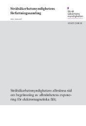
Nomenclature<br />
The nomenclature concerning brittle deformation zones presented by Munier<br />
et al. (2003) <strong>and</strong> meant to be used by SKB in the site characterization work<br />
(Fig. 2-1) is adopted in the present report in order to have a uniform basis for<br />
the discussion <strong>of</strong> results. In the SKB concept <strong>of</strong> brittle deformation zones 2 ,<br />
fixed values <strong>of</strong> fracture density are used to distinguish between fractures<br />
occurring in the host rock (less than 4 fractures/m) <strong>and</strong> fractures inside the<br />
brittle deformation zone (4 or more fractures per m). The core <strong>of</strong> the brittle<br />
deformation zone has a fracture density greater than 9 fractures per metre.<br />
In the special SKB task (Step 2 <strong>of</strong> the SHI) considering analysis <strong>of</strong> kinematic<br />
indicators the SKB concept <strong>of</strong> deformation zones is slightly modified<br />
(Nordgulen <strong>and</strong> Saintot 2006 <strong>and</strong> 2007, Saintot <strong>and</strong> Nordgulen 2007). “The<br />
term fracture zone is used to denote a brittle deformation zone without any<br />
specification whether there has or has not been a shear sense <strong>of</strong> movement<br />
along the zone. A fracture zone that shows a shear sense <strong>of</strong> movement is<br />
referred to as a fault zone” (Nordgulen <strong>and</strong> Saintot 2006 3 ). However, in their<br />
following works, no distinction between brittle deformation zones <strong>and</strong> fault<br />
zones is noted (cf. Nordgulen <strong>and</strong> Saintot 2007, Saintot <strong>and</strong> Nordgulen<br />
2007). The occurrence <strong>of</strong> fault rocks is also presented in the zone definition<br />
by Munier et al. 2003. Nordgulen <strong>and</strong> Saintot (2006) clarify that “The term<br />
fault zone is generally used for brittle structures in which loss <strong>of</strong> continuity<br />
2 The definition <strong>of</strong> brittle deformation zones has a dual character as it contains both structures that are qualitatively<br />
<strong>and</strong> quantitatively measurable (e.g. fractures) in terms <strong>of</strong> fracture density <strong>and</strong> structures that are not<br />
(e.g. crushed rock <strong>and</strong> fault gouge). Note that Munier et al. 2003 do not present any written definition <strong>of</strong> the<br />
term. Why the fixed values 4 fr/m <strong>and</strong> 9 fr/m are chosen as limits for the boundaries <strong>of</strong> brittle deformation<br />
zones <strong>and</strong> the core zones, respectively, are not discussed.<br />
3<br />
The classification scheme for faults (containing structures that are non-cohesive, have secondary cohesion<br />
or are cohesive) suggested by Braathen et al. 2004 (cf. Sibson 1977) is use in kinematic studies. Structures in<br />
the bedrock all have their geological history. This implies that fault rocks belonging to the category <strong>of</strong> structures<br />
that are cohesive or have a secondary cohesion may indicate location <strong>of</strong> fault cores that deviates from<br />
fault cores defined by, for example fractures <strong>and</strong> crushed rock.<br />
SSM <strong>2012</strong>:<strong>71</strong><br />
14
Figure 2-1: <strong>Brittle</strong> deformation zone; host rock – transition zone – core—transition zone—host rock. (From<br />
Munier et al. 2003 <strong>and</strong> modified by Nordgulen <strong>and</strong> Saintot 2006). The transit zone corresponds to the damage<br />
zone (cf. Kim et al. 2003 <strong>and</strong> 2004) <strong>and</strong> damage zone is generally used in the text.<br />
<strong>and</strong> slip occurs on several discrete faults within a b<strong>and</strong> <strong>of</strong> definable width”.<br />
There are no limitations concerning the widths <strong>of</strong> structures denoted brittle<br />
deformation zones or fault zones. Furthermore, the fracture densities can be<br />
measured in scan-lines surveys (in boreholes). However, for optimal positioning<br />
<strong>of</strong> the location <strong>of</strong> the borders <strong>of</strong> a brittle deformation zones (external<br />
borders /zone to host rock/ <strong>and</strong> internal borders /damage zone to core zone/)<br />
a tool, how to measure, <strong>and</strong> guide lines, were to locate, are required.<br />
The classification <strong>of</strong> brittle deformation zones applied by SKB does not give<br />
any information about how <strong>and</strong> where to locate the borders between the host<br />
rock <strong>and</strong> the transition (damage) zone <strong>and</strong> between the transition (damage)<br />
zone <strong>and</strong> the core zone (Fig. 2-1), respectively. Again, a methodology to do<br />
this is needed to obtain a uniform description <strong>of</strong> the architecture <strong>of</strong> deformation<br />
zones. However, this task is not simple as the deformation along a<br />
zone may be heterogeneous <strong>and</strong> the observed structural pattern may be affected<br />
by interference with pre-existing <strong>and</strong> over-printing structures.<br />
For example, Caine et al. (1996) in their description <strong>of</strong> “fault zone architecture<br />
<strong>and</strong> permeable structures” use the terms fault core <strong>and</strong> damage zone to<br />
describe the hydraulic properties in different part <strong>of</strong> a fault zone. They pointed<br />
out that fault cores (according to their definition <strong>of</strong> the term) may consist<br />
<strong>of</strong>:<br />
<br />
<br />
<br />
<br />
<br />
Single fault surfaces.<br />
Unconsolidated clay-rich gouge zones.<br />
Brecciated <strong>and</strong> geochemically altered zones.<br />
Highly indurated cataclastic zones.<br />
Structures which hydraulic character may vary from a localized conduit<br />
to a localized barrier.<br />
SSM <strong>2012</strong>:<strong>71</strong><br />
15
The damage zone (Caine et al. 1996) is a “network <strong>of</strong> subsidiary structures<br />
that bound the fault core <strong>and</strong> may enhance fault zone permeability relative<br />
to fault core <strong>and</strong> the undeformed protolith” (the host rock).<br />
Four types <strong>of</strong> fault zone architecture were distinguished (Caine et al. 1996)<br />
based on the hydraulic character <strong>of</strong> the core zone <strong>and</strong> the width <strong>of</strong> the damage<br />
zone (unsealed fractures). The end members are (cf. Fig 2-2):<br />
<br />
<br />
<br />
<br />
Localized Conduit (core zone <strong>and</strong> no damage zone; I).<br />
Distributed Conduit (conductive core zone <strong>and</strong> damage zones; II).<br />
Combined Conduit-Barrier (conductive damage zone <strong>and</strong> tight core<br />
zone; IV).<br />
Localized barrier (tight core zone <strong>and</strong> no damage zone; III).<br />
Figure 2-2: Conceptual scheme for fault-related fluid flow. Four main groups <strong>of</strong> fault zones related to density<br />
<strong>and</strong> distribution <strong>of</strong> fracture <strong>and</strong> fault gouge (Caine <strong>and</strong> Foster 1993).<br />
Although Cain et al. (1996) introduce a fault zone indices based on the<br />
widths <strong>of</strong> the fault core <strong>and</strong> damage zones. However, they do not discuss<br />
how the widths should be measured. Furthermore, the conceptual fault zone<br />
model presented by Caine et al. (1996) always contains a core zone. Kim et<br />
al. (2003 <strong>and</strong> 2004) discuss in more detail the concept <strong>of</strong> fault damage zone.<br />
The brittle deformation zone nomenclature presented by Munier et al.<br />
(2003) is not genetic. However, where core zones appear in a SKB brittle<br />
deformation zone model they are denoted fault cores (Stephens et al. 2008,<br />
Appendix Table A-4). Furthermore, Munier et al. (2003) include in their<br />
schematic illustration <strong>of</strong> brittle deformation zones also fault rocks in the<br />
core zone, e.g. fault gouge, without a discussion whether the fault rock is<br />
cohesive (sealed) or not. The character <strong>of</strong> fault rocks has been described <strong>and</strong><br />
discussed by, for example Sibson (1977), Braathen et al. (2004) <strong>and</strong> Milnes<br />
(2006). Once again, many early ductile deformation zones have also acted<br />
SSM <strong>2012</strong>:<strong>71</strong><br />
16
as precursor for brittle deformation, i.e. all deformed rock found within a<br />
brittle deformation zone may not be brittle in character.<br />
All structures formed in the bedrock are more or less affected by the geologic<br />
evolution since the structures were formed. Precipitation <strong>of</strong> fracture mineral<br />
<strong>and</strong> weathering <strong>of</strong> fracture walls <strong>and</strong> fills are example <strong>of</strong> processes that<br />
decreases the water permeability in fractures, while changes in the stress<br />
field may cause disturbances that keep structures open or reopen structures.<br />
Furthermore, when characterizing a brittle deformation zone it is an advantage<br />
to have the structure well exposed so the structural relation between<br />
different parts <strong>of</strong> the structure can be studied <strong>and</strong> also how structures inside<br />
the zone is related to structures in the host rock outside the zone. Such<br />
knowledge is useful when performing structural interpretation <strong>of</strong> borehole<br />
data.<br />
The strength <strong>of</strong> the rock within, for example, a brittle deformation zone is<br />
generally not uniform (cf. Fig. 2-2). This is, as pointed out above, partly due<br />
to the interplay between fragile deformations <strong>and</strong> sealing processes. In rock<br />
engineering <strong>and</strong> construction the main concerns are related to the actual<br />
properties <strong>and</strong> behaviour <strong>of</strong> the rock (Palmstrøm 1995), especially zones <strong>of</strong><br />
weakness. The general term “weakness zone” denotes "a part or zone in the<br />
ground in which the mechanical properties are significantly lower than in<br />
the surrounding rock mass. <strong>Weakness</strong> zones can be faults, shears/shear<br />
zones, thrust zones, weak mineral layers, etc." (Norwegian Rock Mechanics<br />
Group, 2000, Palmstrøm <strong>and</strong> Broch 2006). This implies that weakness<br />
zones may fully coincide with or only form a minor part <strong>of</strong> brittle deformation<br />
zones. If a brittle deformation zone is sealed then it may not form a<br />
zone <strong>of</strong> weakness (although it will form a scar). However, brittle zones may<br />
reactivate <strong>and</strong> the probability for reactivation <strong>of</strong> sealed zones is very little<br />
studied (not known to the author). What is described is that reactivations<br />
occur.<br />
An alternative methodology (cf. SKB geological Single Hole Interpretation,<br />
SHI, described in the following section) to identify sections <strong>of</strong> fractured <strong>and</strong><br />
weak rock in boreholes is given in subsequent sections. First a review <strong>of</strong> the<br />
SKB approach is given.<br />
Review <strong>of</strong> SKB Geological Single Hole Interpretations<br />
<strong>and</strong> location <strong>of</strong> zones<br />
The main aim <strong>of</strong> the SKB geological Single Hole Interpretation (SHI: SKB<br />
MD 810.003, version 3.0) is to support the construction <strong>of</strong> deterministic<br />
three-dimensional geological models <strong>and</strong> stochastic DFN modelling <strong>of</strong> fractures<br />
in the rock outside brittle deformation zones. The input data are geological<br />
<strong>and</strong> geophysical borehole data (<strong>and</strong> borehole TV; BIPS) <strong>and</strong> the classification<br />
<strong>of</strong> data embrace rock units (RU; rock type) <strong>and</strong> possible deformation<br />
zones (DZ). Interactive control <strong>of</strong> interpretation by visual inspection<br />
<strong>of</strong> the core is performed to refine the classification. The process <strong>of</strong> interpretation<br />
<strong>of</strong> deformed rock within the SHI investigation is made in two steps:<br />
Step 1: A general description <strong>of</strong> the character <strong>of</strong> deformation zones<br />
(DZ’s; e.g. brittle, ductile or transitional) <strong>and</strong> a detailed description <strong>of</strong><br />
SSM <strong>2012</strong>:<strong>71</strong><br />
17
parameters supporting the identification <strong>of</strong> each zone. The confidence <strong>of</strong><br />
the zone interpretation is also given (3 classes: high, medium <strong>and</strong> low).<br />
Step 2: Focused on characterization <strong>of</strong> zones with high confidence (step<br />
1) regarding the following parameters: type <strong>of</strong> deformation across zones,<br />
characterization <strong>of</strong> fault rock, location <strong>of</strong> core zones <strong>and</strong> kinematic analysis.<br />
The parameter information should be complemented with a short<br />
interpretation <strong>of</strong> the structural evolution <strong>of</strong> the zone. The second step is<br />
reported separately.<br />
It is stated that the Single Hole Interpretation (SHI) is the first action regarding<br />
zone interpretation <strong>and</strong> it is separated from a second action (the Extended<br />
Single Hole Interpretation; ESHI) when more precise locations <strong>of</strong> deformation<br />
zones are determined. The ESHI is performed during the actual modelling<br />
<strong>of</strong> structures in three dimensions. For identification <strong>of</strong> SHI/ESHI there<br />
is no limitation regarding the size <strong>of</strong> their extension along the boreholes. In<br />
the Geological Single Hole Investigation the fracture frequency statistics is<br />
presented as floating averages (e.g. 5 m window <strong>and</strong> 1 m steps) for all fractures,<br />
open fractures, partly open fractures, sealed fractures <strong>and</strong> sealed fracture<br />
networks. The floating average statistics has a smoothing effect on the<br />
fracture frequency curves.<br />
In summary, the SHI <strong>and</strong> ESHI classification should be better described by<br />
SKB regarding systematics <strong>and</strong> applied methodology in the classification<br />
process to obtain a uniform classification process that is fully transparent <strong>and</strong><br />
reproducible. This holds especially for the ESHI classification as it appears<br />
not to have a comprehensive method description. The results <strong>of</strong> the<br />
SHI/ESHI (the location <strong>of</strong> interpreted structures) are stored in the SKB database<br />
SICADA.<br />
In the Forsmark area the number <strong>of</strong> indicated intersections <strong>of</strong> brittle deformation<br />
zones in boreholes (KFM01A-10A; 23 cored boreholes with a total<br />
length <strong>of</strong> about 15 km) was 114 in the first SHI step <strong>and</strong> they constitute 24.5<br />
percent <strong>of</strong> the total mapped core length. The second classification step<br />
(ESHI) introduced 12 more potential zone intersections <strong>and</strong> adjustments <strong>of</strong><br />
the position <strong>of</strong> 10 SHIs. Thereby the length <strong>of</strong> potential intersections <strong>of</strong> brittle<br />
deformation zones in the boreholes increased by slightly less than ten<br />
percent (9.8) so that the ESHI intersections occupies about 26.9 percent <strong>of</strong><br />
the total length <strong>of</strong> mapped cores (ESHI; range in width from 0.5 to 215 mbl.<br />
<strong>and</strong> the mean value is 32 mbl.). The shallower part <strong>of</strong> the bedrock in the<br />
Forsmark area is notably more fractured than its deeper parts <strong>and</strong> in spite <strong>of</strong><br />
this about 46 percent <strong>of</strong> all ESHI are located at depth below 300 m a.s.l. 4 ,<br />
note that most boreholes are target-drilled. However, it is beyond the scope<br />
<strong>of</strong> this study to elaborate on this further.<br />
In the study <strong>of</strong> kinematic indicators to identify shear displacement along<br />
faults a selected number <strong>of</strong> SHI DZ sections (84) were studied (cf. Appendix<br />
Table A-4 in Stephens et al. 2008) <strong>and</strong> the more intensely deformed sections<br />
forming the fault core (cf. Fig. 2-1) were identified. Amongst the studied<br />
SHI DZ sections 52 percent contain fault cores (no tables compiling width<br />
<strong>and</strong> location <strong>of</strong> fault cores was found by the author) <strong>and</strong> 79 percent <strong>of</strong> the<br />
4 m a.s.l. is the abbreviation for metres above sea level.<br />
SSM <strong>2012</strong>:<strong>71</strong><br />
18
investigated SHI DZ sections were included in the 2.3 version <strong>of</strong> the geological<br />
SDM for Forsmark.<br />
A final remark is that the all SHI DZ are used as input data in the SKB structural<br />
modelling process, i.e. the construction <strong>of</strong> the geological Site Descriptive<br />
Model (SDM). The boundaries <strong>of</strong> the zones may be adjusted during the<br />
modelling (transformed to ESHI) <strong>and</strong> all SHI DZ sections in boreholes may<br />
not be included in the presented model. Due to criteria for including structures<br />
about 35% <strong>of</strong> the number <strong>of</strong> all SHI DZ sections, i.e. about 19 percent<br />
<strong>of</strong> the total length <strong>of</strong> all SHI DZ sections in boreholes, are not included in<br />
the 2.3 version <strong>of</strong> the geological SDM for Forsmark. However, in the geological<br />
SDM several structures are not intersected by boreholes but indicated<br />
by ground geophysics only.<br />
Classification system for identification <strong>of</strong><br />
brittle deformation zones <strong>and</strong> weakness<br />
zones in boreholes<br />
During an initial stage <strong>of</strong> the present study, an attempt to increase the resolution<br />
in the interpretation <strong>of</strong> fracture data from boreholes was made by studying<br />
fracture frequency in intervals <strong>of</strong> 0.5 mbl. The idea is simple <strong>and</strong> assumes<br />
that an increase in the resolution in the interpretation will increase the<br />
underst<strong>and</strong>ing <strong>of</strong> the distribution <strong>of</strong> fractures along the boreholes. However,<br />
by applying fracture statistics, averaging data, the direct coupling between<br />
base data <strong>and</strong> fracture characteristics was lost. Furthermore, averaging over<br />
fixed distances may suppress structures that are thinner than the interval<br />
width used in the statistics.<br />
Instead <strong>of</strong> using intervals along which fracture characteristics can be averaged,<br />
the mutual separation between fractures is used to identify clusters <strong>of</strong><br />
fractures. This is to apply a fracture-scale resolution. Separation between<br />
fractures can be transformed into fracture densities/frequencies, when such<br />
measures are needed. Calculation <strong>of</strong> mutual separation between observations<br />
can be made in the base data tables (in this case in an added column for data<br />
in the worksheet) maintaining the coupling between the separation <strong>of</strong> fractures<br />
<strong>and</strong> the character <strong>of</strong> fractures in the base table. This ensures optimum<br />
resolution in the classification <strong>of</strong> data.<br />
A classification system should require the following:<br />
1. The classification system should be objective.<br />
2. Input data should be available in a treatable format; data to classify <strong>and</strong><br />
information that might affect the classification system (data on the geological<br />
environment within which the object for classification is located).<br />
3. The classification should be systematic <strong>and</strong> uniform, i.e. being transparent<br />
<strong>and</strong> reproducible.<br />
4. Clear steps in the classification process <strong>and</strong> presentation <strong>of</strong> refinements<br />
<strong>of</strong> the classification for each step.<br />
5. Simple to make sensitivity tests, i.e. test outcome against chosen parameters<br />
steering the classification.<br />
SSM <strong>2012</strong>:<strong>71</strong><br />
19
6. Presentation <strong>of</strong> results is a communication process <strong>and</strong> should be customised<br />
<strong>and</strong> observation regarding relations between data sets (geometric<br />
or genetic) be described <strong>and</strong> visualized.<br />
The objective <strong>of</strong> the classification system<br />
The objective <strong>of</strong> the classification system presented in this study is to sort<br />
out sections along boreholes that may represent structures in the bedrock that<br />
affect its mechanical strength <strong>and</strong> the flow <strong>of</strong> groundwater, i.e. weakness<br />
zones. At the same time, sections with a general increase in fracture density<br />
(considering all fractures) that may represent brittle deformation zones are<br />
located. However, the effort is not to identify extensive discrete fracture<br />
planes (cf. large fractures, SKB 2010).<br />
Input data<br />
Basic input data comprise the fracture logs (including discrete fractures,<br />
crushed rock, <strong>and</strong> core loss). Data describing the geological environment are<br />
lithological logs (including rock types, orientation <strong>of</strong> lithological contacts,<br />
<strong>and</strong> alteration <strong>of</strong> the bedrock), data on ductile deformation (foliation <strong>and</strong><br />
ductile shear zones), data on zones formed by brittle deformation (brittleductile<br />
shear zones, cataclastic rock, breccia, “sealed network <strong>of</strong> fractures”,<br />
crushed rock <strong>and</strong> core loss), borehole radar data (absolute orientation <strong>of</strong> reflectors)<br />
<strong>and</strong> data on fluid transport into or out from the borehole (flow logs<br />
/e.g. PFL/). Borehole TV-logs (BIPS) have been used during the SKB mapping<br />
<strong>of</strong> the cores to orient structural features. The BIPS method can be used<br />
to obtain detailed in situ pictures <strong>of</strong> structural relationships. However, BIPS<br />
data have unfortunately not been used in the present study to support the<br />
presented classification <strong>of</strong> drill cores. In this study, classified fracture data<br />
are presented in composite logs together with locations <strong>of</strong> water-conductive<br />
structures.<br />
Systematic <strong>and</strong> uniform classification<br />
Important in all classification systems is that the nomenclature <strong>and</strong> classification<br />
procedure are well defined <strong>and</strong> the system is applicable within a wide<br />
range <strong>of</strong> fracture densities. The simpler a classification system is the higher<br />
is its reproducibility <strong>and</strong> transparency. However, the identification <strong>of</strong> sections<br />
<strong>of</strong> increased fracturing can be based on relative increases in fractures<br />
frequencies (relative to the general fractures density in investigated borehole)<br />
or by using fixed absolute values regarding fracture separation (used<br />
here, however, by choosing small numbers the difference will be minor)<br />
when setting class boundaries. Progressive refinement in the classification<br />
procedure may be conducted (cf. item 4 in first part <strong>of</strong> this section).<br />
Clear steps in the classification process<br />
A stepwise performed classification procedure will enhance the underst<strong>and</strong>ing<br />
<strong>of</strong> data <strong>and</strong> it also dem<strong>and</strong>s arguments for each performed step. Interac-<br />
SSM <strong>2012</strong>:<strong>71</strong><br />
20
tivity in the process provides feedback <strong>and</strong> forms the base for refinements <strong>of</strong><br />
the classification.<br />
Sensitivity tests<br />
Tests <strong>of</strong> sensitivity can be made part <strong>of</strong> the classification system. This is<br />
simple when the classification is based on one parameter but becomes more<br />
intricate when the classification is based on two or more parameters. For<br />
fracture distribution <strong>and</strong> identification <strong>of</strong> clusters, three parameters should be<br />
considered:<br />
1. Minimum number <strong>of</strong> fractures in a cluster.<br />
2. Minimum mutual distance <strong>of</strong> fractures.<br />
3. Selection <strong>of</strong> fracture population (for example; all, open or sealed fractures<br />
<strong>and</strong> fresh versus altered fracture <strong>and</strong> sets <strong>of</strong> fractures or a combination<br />
<strong>of</strong> these fracture characteristics).<br />
The sensitivity test performed in this study (Chapter 4 Discussion) considers<br />
all fractures in one borehole section (KFM10A). The test consists <strong>of</strong> changing<br />
the minimum number <strong>of</strong> fractures to form clusters (4±1) <strong>and</strong> also varies<br />
the minimum mutual separation between fractures to outline clusters (from<br />
0.1 <strong>and</strong> 0.2 to 0.5 mbl.; the latter corresponding to a minimum fracture frequency<br />
<strong>of</strong> 2 fractures per metre borehole length 5 ).<br />
Presentation <strong>of</strong> results<br />
The presentation <strong>of</strong> results should be performed is such manner that the results<br />
can be easily used by other geodisciplines <strong>and</strong> also in such a way that it<br />
communicates the essence <strong>of</strong> the result <strong>of</strong> the classification. The former can<br />
be done by presenting tables while the latter can be made by visualization <strong>of</strong><br />
results (composite logs or three dimensional figures showing, e.g. structural<br />
relationships). Both presentations should be accompanied by descriptive<br />
text.<br />
Step by step performance – identification<br />
<strong>of</strong> sections with increased fracturing in<br />
boreholes<br />
Classification <strong>of</strong> brittle deformation may in well exposed areas be based on<br />
continuous mapping <strong>of</strong> structures along their extent. However, such areas are<br />
relatively rare. <strong>Deformation</strong> zones are <strong>of</strong>ten more easily eroded than the host<br />
rock why they form depressions in the bedrock surface <strong>and</strong> <strong>of</strong>ten are, evenly<br />
in relatively well exposed areas, covered by soil.<br />
The classification procedures used (Chapters 3, 4 <strong>and</strong> 5) are based on borehole<br />
data <strong>and</strong> consist <strong>of</strong> sequences <strong>of</strong> steps. The first step (cf. section Data<br />
h<strong>and</strong>ling below) involves selection <strong>of</strong> data to base the classification on. The<br />
5 fr/mbl. is the abbreviation for “fractures per metre borehole length”.<br />
SSM <strong>2012</strong>:<strong>71</strong><br />
21
subsequent steps consider how to locate sections in the borehole representing<br />
possible locations <strong>of</strong> brittle deformation zones <strong>and</strong> weakness zones.<br />
The use <strong>of</strong> relative density <strong>of</strong> fractures to identify potential location <strong>of</strong> brittle<br />
deformation zones requires good overview regarding the general homogeneity<br />
<strong>of</strong> fracturing along the boreholes. The SKB definition <strong>of</strong> a brittle deformation<br />
zone (Fig. 4-2) applies fixed values on fracture frequencies. A brittle<br />
deformation zone may have core zone/-s for which the density <strong>of</strong> fractures is<br />
set by SKB to be greater than 9 fractures per metre 6 . However, this fracture<br />
frequency cannot directly be compared with, for example, the RQD (Rock<br />
Quality Designation, see Formula 1 below) as the RQD considers fractures<br />
parting the core. For core sections with core pieces equal to or shorter than<br />
0.10 m the RQD is zero. Furthermore, some <strong>of</strong> the fractures breaking the<br />
core may be broken up during drilling <strong>and</strong> h<strong>and</strong>ling <strong>of</strong> the core.<br />
RQD (Deere 1964) is defined as the quotient in percent:<br />
(Formula 1)<br />
l sum <strong>of</strong> 100= Sum <strong>of</strong> length <strong>of</strong> all core sticks longer than 100 mm measure along the<br />
centre line <strong>of</strong> the core (in the measured section)<br />
l tot core run= total length <strong>of</strong> core run (the measured section).<br />
However, it is not apparent what fractures are to be considered in the SKB<br />
definition <strong>of</strong> brittle fractures (all fractures?). In the classification presented<br />
here, all fractures are used initially to locate possible positions <strong>of</strong> brittle deformation<br />
zones. On the other h<strong>and</strong>, to locate weakness zones open altered<br />
fractures are used 7 , i.e. a sub-group <strong>of</strong> all fractures parting the core (cf.<br />
RDQ). However, using all fractures to identify fracture zones may be cumbersome<br />
in bedrock with high average fracture densities, especially when the<br />
fracture population is composed <strong>of</strong> a mix <strong>of</strong> several sets <strong>of</strong> fractures (cf.<br />
Chapter 3). That is, the clusters may represent, for example, cross-cutting<br />
zones or a more or less r<strong>and</strong>om interference <strong>of</strong> fracture sets. In such cases,<br />
each set <strong>of</strong> fractures are to be treated separately. Furthermore, identification<br />
<strong>and</strong> characterization <strong>of</strong> zones is a learning exercise. During the interpretation<br />
supporting data on potential zones should be kept together with data (e.g. in<br />
the same worksheet) on fractures outside the zone. By comparing fracture<br />
sets inside <strong>and</strong> outside a zone, fractures that may predate or overprint the<br />
zone may be indicated.<br />
In this work, one approach is to let fracture clusters with a fracture frequency<br />
<strong>of</strong> 10 or more 4 open altered fracture per metre borehole length to be used to<br />
6 The definition <strong>of</strong> brittle deformation zones presented by Munier et al. (2003) considers both the fracture<br />
density <strong>and</strong> the occurrence <strong>of</strong> fault rock (cf. Sibson 1977, Milnes 2006). The fault rocks, except for sections<br />
mapped as crushed rocks are in the Forsmark site cohesive, i.e. form different types <strong>of</strong> rock, cf. tectonite.<br />
Crushed rock is by the definition applied by SKB composed <strong>of</strong> open fractures while “sealed network <strong>of</strong> fractures”<br />
appears as a system <strong>of</strong> hair-line fractures <strong>and</strong> breccia is a fragmented rock held together by mineral<br />
cement or fine-grained matrix.<br />
7 However, the selection <strong>of</strong> fractures can be discussed. Fractures mapped as open can be: a. open fresh<br />
without fracture minerals, b. open fresh with fracture minerals, c. open altered without fracture minerals <strong>and</strong> d.<br />
open altered with fracture minerals. Fresh fractures may either been broken up during drilling or h<strong>and</strong>ling <strong>of</strong><br />
drill cores or representing non-connected fractures or fractures that have been open up very late. Open<br />
altered fractures have been chosen as such fractures have been affected by the groundwater. This issue is<br />
treated further in the Chapter 4 Discussion, section Sensitivity test.<br />
SSM <strong>2012</strong>:<strong>71</strong><br />
22
indicate the core zone <strong>of</strong> weakness zones. Similarly, the core zone <strong>of</strong> a brittle<br />
deformation zone should be defined as fracture clusters contain 10 or more<br />
fractures per metre considering open, partly open <strong>and</strong> sealed fractures together.<br />
Sections <strong>of</strong> crushed rock are initially not considered. However, they<br />
are at a later stage in the process considered as parts <strong>of</strong> core zones.<br />
As a guide to locating the contact between the core zones <strong>and</strong> the outer rim<br />
<strong>of</strong> a brittle deformation zone (the damage/transition zone), clusters with a<br />
fracture density that is half the density <strong>of</strong> fractures in clusters outlining the<br />
core zone/-s can be applied for the damage zone (i.e. in this case fracture<br />
separation <strong>of</strong> 0.20 m or less; cf. 4 fr/m is suggested by Munier et al. 2003 for<br />
the transition zone).<br />
However, the separation <strong>of</strong> fractures along a borehole is related to the angular<br />
relation between the borehole <strong>and</strong> the fractures (the alpha angle). This<br />
relation can be considered by separate analysis <strong>of</strong> sets <strong>of</strong> fractures <strong>and</strong> recalculate<br />
the separation <strong>of</strong> fractures along the borehole to true separations<br />
(separation along borehole = (true separation)/sin; 8 is the intersection<br />
between the borehole <strong>and</strong> the fracture; cf. sampling bias, Terzaghi 1965).<br />
In the classification system presented in this study the separation between<br />
fractures is used as a relative measure. The advantage <strong>of</strong> this is that it gives<br />
precise locations for sections classified as brittle deformation zones or<br />
weakness zones. When a section <strong>of</strong> increased fracturing is identified its fracture<br />
frequency can be calculated. Furthermore, the original data are retained<br />
during the classification <strong>and</strong> the character <strong>of</strong> fractures within each outlined<br />
interval can be directly described. This holds also for fractures outside <strong>and</strong><br />
adjacent to zones.<br />
The next parameter in the classification system is the number <strong>of</strong> fractures<br />
needed to “identify” a zone. Definition <strong>of</strong> brittle deformation zones does<br />
generally not give a unique number regarding the number <strong>of</strong> fracture needed<br />
(in a cross section). A fault zone must contain at least one fracture along<br />
which displacement has taken place (Caine et al. 1993, cf. Fig. 2.2). Three<br />
fractures are needed to outline two sections in the core. Choosing three fractures<br />
gives a high resolution but it may, however, comprise large parts <strong>of</strong> the<br />
fractures in the core. However, it gives the possibility to check the sensitivity<br />
<strong>of</strong> the classification system as sections with four <strong>and</strong> more fractures will be<br />
listed simultaneously (part <strong>of</strong> the sensitivity test, cf. Chapter 4). However, in<br />
the base case clusters formed by at least four fractures was performed in this<br />
study (Chapter 3).<br />
The last step is to join adjacent cluster to outline zones (Chapter 4) according<br />
to the applied definition <strong>of</strong> zones. This step need also, except from the minimum<br />
magnitude <strong>of</strong> fracture frequencies in core <strong>and</strong> damage zones, guidance<br />
regarding how to locate the boundaries <strong>of</strong> zones. This step also draws attention<br />
to inhomogeneity in zones.<br />
8 Data on intersection angles (α) between the borehole axis <strong>and</strong> fractures are presented in SKBs databas<br />
SICADA.<br />
SSM <strong>2012</strong>:<strong>71</strong><br />
23
Input data<br />
The SKB fracture log (SKB SICADA base; data file p_fract_core-<br />
KFMXXY 9 ) contains several fracture parameters, for example Borehole<br />
ID 10 *, position in borehole (adjusted secup*), if the core is broken/unbroken*<br />
<strong>and</strong> if fractures are open/partly open/sealed*, width <strong>and</strong> aperture<br />
(*) <strong>of</strong> fractures, confidence in the presented aperture (3 classes), types <strong>of</strong><br />
fracture fills*, morphology <strong>of</strong> fractures (planar to irregular), roughness <strong>of</strong><br />
fracture surfaces, indication <strong>of</strong> displacement along fractures, fracture alteration*,<br />
orientation (strike/dip*), type <strong>of</strong> host rock <strong>and</strong> absolute coordinates <strong>of</strong><br />
observations.<br />
Data h<strong>and</strong>ling<br />
The identification <strong>of</strong> clusters <strong>of</strong> fractures along the borehole is best made<br />
using a worksheet (e.g. Excel). During the analysis all base data for each<br />
analysed group <strong>of</strong> fracture are kept <strong>and</strong> the space for noting the outcome <strong>of</strong><br />
analysis is obtained by adding columns in the base data table.<br />
The steps in the data h<strong>and</strong>ling are as follows:<br />
1. Select a group <strong>of</strong> fractures (e.g. all, open, partly open or sealed or set <strong>of</strong><br />
fractures – in this case all <strong>and</strong> thereafter open altered fractures are chosen<br />
<strong>and</strong> in some cases also sets <strong>of</strong> fractures).<br />
2. Calculate the mutual separation between fractures along the core for the<br />
selected group <strong>of</strong> fractures.<br />
3. Give the parameters for the cluster identification (minimum number <strong>of</strong><br />
fractures <strong>and</strong> maximum separation between the fractures; in this case<br />
minimum 4 fractures <strong>and</strong> 0.10 <strong>and</strong> 0.20 m => the two cluster parameters<br />
to identify core zone <strong>and</strong> damage zone, respectively) <strong>and</strong> apply these<br />
parameters to the data. Give upper position, lower position <strong>and</strong> number<br />
<strong>of</strong> fractures for identified clusters in separate columns.<br />
4. If distinct fracture sets exist repeat the analysis for each set <strong>and</strong> consider<br />
the orientation bias when applying fracture separation for different classes<br />
<strong>of</strong> clusters (i.e. repeat steps 1 to 3).<br />
5. Compile cluster data obtained <strong>and</strong> present a summary table (for example<br />
Tables 11 3-6, 3-12 or 3-16) <strong>and</strong> visualize the location <strong>of</strong> the clusters in a<br />
composite diagram (for example Figs. 3 3-61, 3-101 <strong>and</strong> 3-132).<br />
Performance<br />
The step-wise analysis presented below (step A to E) <strong>and</strong> performed in<br />
Chapters 3 <strong>and</strong> 4 forms the base for the developed approach <strong>of</strong> localizing<br />
zones. The outcome <strong>of</strong> the performed analysis is presented in Chapter 5,<br />
9 KFMXX: K=kärnborrhål (cored borehole), FM=Forsmark, <strong>and</strong> XXY is the number <strong>of</strong> the borehole, for instance<br />
01A.<br />
10 Parameters noted with * are used in this study. Fracture apertures (*) are only used in borehole KFM10A<br />
(Chapter 4; cf. Table 4-3).<br />
11 Chosen examples give zone to borehole intersections at various depths <strong>and</strong> several groups <strong>of</strong> fractures<br />
/clusters are treated.<br />
SSM <strong>2012</strong>:<strong>71</strong><br />
24
Results <strong>and</strong> conclusions, <strong>and</strong> a somewhat refined performance to locate <strong>and</strong><br />
describe brittle deformation zones <strong>and</strong> weakness zones is presented.<br />
Step A<br />
This initial step considers all data <strong>and</strong> provides an overview <strong>of</strong> the spatial<br />
distribution <strong>of</strong> fractures along the borehole (cf. data h<strong>and</strong>ling above).<br />
The aim is to identify borehole sections that in geological time have been<br />
affected by brittle deformation. However, using all fractures may not indicate<br />
which section(s) <strong>of</strong> the borehole that today have potential to contain<br />
fractures with low tensile strength or water-conducting fractures. On the<br />
other h<strong>and</strong>, it may give information about fracture sets that together form the<br />
cluster <strong>and</strong> how the fracture pattern inside the clusters are related to the fracture<br />
pattern outside the clusters.<br />
Step B<br />
The data examined in the next step are all open fracture, i.e. including fractures<br />
breaking the core <strong>and</strong> where the core pieces do not exactly match. The<br />
base for this choice is an assumption that these discrete fractures contain the<br />
weak fractures (cf. Chapter 4; interpretation <strong>of</strong> broken sealed <strong>and</strong> altered<br />
open fractures) <strong>and</strong> the water-conductive fractures (number <strong>of</strong> weak fracture<br />
are greater or equal to the number <strong>of</strong> water conductive fractures?).<br />
This step indicates the relative distribution <strong>of</strong> open fractures in relation to all<br />
fractures, i.e. it could give information about the present effective width <strong>of</strong><br />
zones.<br />
However, amongst the open fractures there are those with fresh surfaces <strong>and</strong><br />
those with altered fracture surfaces. In most cases open fractures with fresh<br />
surfaces are subordinate <strong>and</strong> they have similar orientations as open altered<br />
fractures why this step is not performed in all boreholes (due to time <strong>and</strong><br />
budget constraints).<br />
Step C<br />
In this step open altered fractures are analysed. These fractures represent<br />
weak fractures <strong>and</strong> the alteration <strong>of</strong> the fractures indicates that they have<br />
been in contact with fluids.<br />
This step may indicate whether or not flowing groundwater has been focused<br />
along narrow sections in the rock.<br />
Steps A <strong>and</strong> C are demonstrated in Chapter 3 for selected borehole sections;<br />
sections that are located in seven cored boreholes where they cross a gently<br />
inclined zone.<br />
SSM <strong>2012</strong>:<strong>71</strong><br />
25
Step D<br />
A sensitivity test checking the outcome (location <strong>and</strong> size <strong>of</strong> clusters) by<br />
using alternative criteria for the identification <strong>of</strong> clusters, i.e. use variable<br />
minimum number <strong>of</strong> fractures to be included <strong>and</strong> minimum mutual separation<br />
<strong>of</strong> fractures to outline clusters. (In the present study only executed is the<br />
sensitivity test for fracture data in a selected section <strong>of</strong> borehole KFM10A,<br />
Chapter 4).<br />
Step E<br />
Steps A to D are performed to locate clusters, i.e. potential locations for brittle<br />
deformation zones <strong>and</strong> weakness zones. In the discussion chapter (Chapter<br />
4) a next step (step E) is proposed regarding joining closely spaced clusters<br />
together in order to define the borders <strong>of</strong> potential zones. As pointed out<br />
already, this step needs rules for the location <strong>of</strong> zone borders. The identification<br />
<strong>of</strong> zones is a learning process <strong>and</strong> it is important to use reference structures<br />
(mapped on exposed rock surfaces <strong>and</strong>/or experience gained during the<br />
construction <strong>of</strong> geological models) to support the interpretation <strong>of</strong> borehole<br />
structures.<br />
Fractures with measurable apertures<br />
In the Forsmark bedrock there are relative few fractures with apertures<br />
greater than the resolution <strong>of</strong> the BIPS instrument. However, many <strong>of</strong> these<br />
fractures appear as solitary fractures <strong>and</strong> are located outside clusters <strong>of</strong> fractures<br />
(cf. Chapter 4) <strong>and</strong> some <strong>of</strong> these fractures are noted as fresh. Some<br />
comments on fractures having noted apertures greater than 0.5 mm are given<br />
in Chapter 4 (cf. Table 4-6).<br />
SSM <strong>2012</strong>:<strong>71</strong><br />
26
3. Description <strong>of</strong> borehole<br />
data <strong>and</strong> zone intersections<br />
The selected area for the present study is the SKB Forsmark site in northern<br />
Uppl<strong>and</strong>, about 120 km north <strong>of</strong> Stockholm. The area is one <strong>of</strong> the most<br />
studied areas in Sweden regarding location <strong>and</strong> character <strong>of</strong> deformation<br />
zones as it is the selected area for underground characterization <strong>of</strong> the bedrock<br />
(SKB 2008 <strong>and</strong> references therein). It is the proposed site for building a<br />
final repository for high-level nuclear waste in Sweden.<br />
The investigation <strong>of</strong> the Forsmark area (Figs. 3.1 to 3-3) has indicated the<br />
existence <strong>of</strong> brittle deformation zones having relative large extensions. One<br />
<strong>of</strong> the zones (gently inclined) is penetrated by several cored boreholes at<br />
various depths (Table 3-1 <strong>and</strong> Figs. 3-1 <strong>and</strong> 3-5). This is advantageous in a<br />
method study, i.e. that the studied object is a single structure. However, the<br />
studied structure may not originally be uniform along its extent <strong>and</strong> it is clear<br />
that the structure locally interferes with other structures or has superimposed<br />
alteration. Still, it is the same structural unit that may have some common<br />
characteristic features conserved.<br />
Examples to illustrate the character <strong>of</strong> the bedrock inside <strong>and</strong> in the vicinity<br />
<strong>of</strong> deformation zones are given in this chapter. The methodology using fracture<br />
separations to identify fracture clusters, presented in the previous chapter,<br />
is applied (steps A to C). The main studied object is a gently inclined <strong>and</strong><br />
extensive brittle deformation zone in the SKB Forsmark site; SKB brittle<br />
deformation zone ZFMA2 (Fig. 3-5; cf. Stephens et al. 2007, Stephens et al.<br />
2008, <strong>and</strong> SKB 2008). Sub-vertical brittle deformations zones trending ENE<br />
<strong>and</strong> NW are also described when occurring adjacent to zone ZFMA2 in<br />
boreholes (Figs. 3-4, 3-6 <strong>and</strong> 3-7). Fractures described in this report are discrete<br />
fractures (SKB database SICADA files p_fract_core-KFMXXY.xls) if<br />
not nothing else is presented.<br />
The locations <strong>of</strong> zone ZFMA2 <strong>and</strong> other SKB zones intersecting the investigated<br />
sections in the seven core-drilled holes are briefly described in the first<br />
section <strong>of</strong> this chapter <strong>and</strong> the second section (the main part <strong>of</strong> this report)<br />
presents the character <strong>of</strong> the seven investigated borehole sections.<br />
Borehole KFM01B, section 12.5-120 mbl., is described in more detail than<br />
the intersections in the other six boreholes. The reason for this is to select<br />
categories <strong>of</strong> fractures essential for identification <strong>and</strong> characterization <strong>of</strong><br />
sections with brittle deformation affecting the present strength <strong>of</strong> the bedrock<br />
<strong>and</strong> transport paths for groundwater. The borehole also emphasises the<br />
difference in fracture characteristics at shallow levels (depths less than 50 m)<br />
<strong>and</strong> at deeper levels <strong>of</strong> the bedrock.<br />
The section describing fracture characteristics in borehole KFM04A is also<br />
extended as the borehole is located within the rim <strong>of</strong> a regional scale NW-SE<br />
SSM <strong>2012</strong>:<strong>71</strong><br />
27
trending ductile shear zone at the western border <strong>of</strong> the Forsmark site, <strong>and</strong><br />
the ductile zone has partly been re-activated as a set <strong>of</strong> brittle deformation<br />
zones.<br />
Brief characterizations <strong>of</strong> the bedrock in <strong>and</strong> adjacent to the brittle zone<br />
ZFMA2 are given for the remaining six boreholes (KFM01B, 01C, 2A, 2B,<br />
5A <strong>and</strong> 10A). For each <strong>of</strong> the seven boreholes, a compiled structural geologic<br />
log which also contains hydrogeological data is provided.<br />
The hydrogeological borehole measurement used is the Posiva Flow Log<br />
(PFL; Öhberg <strong>and</strong> Rouhiainen 2000) <strong>and</strong> noted are all locations along the<br />
boreholes with indicated flow (the magnitude <strong>of</strong> the flows is not considered<br />
in the present study).<br />
The only geophysical data used in this chapter <strong>of</strong> the report are obtained by<br />
the borehole radar measurements. The borehole data are used to support<br />
orientation <strong>of</strong> structures, for example, water-conductive structures.<br />
In the discussion chapter (Chapter 4), a comparison between geological <strong>and</strong><br />
geophysical data from another borehole (KFM09A) located in the northwestern<br />
part <strong>of</strong> the Forsmark site is made. This is done in order to test the<br />
distribution <strong>of</strong> fracture clusters against the outcome <strong>of</strong> the statistical analysis<br />
(cluster analysis) applied on borehole geophysical data in order to detect<br />
brittle deformation zones (Sträng et al. 2010 <strong>and</strong> Tirén et al. 2009).<br />
Investigated area – structures <strong>and</strong> boreholes<br />
Most <strong>of</strong> the boreholes used in this study are relatively closely located within<br />
the southern part <strong>of</strong> the SKB target area, where also the gently zone is situated,<br />
while the separation between these boreholes <strong>and</strong> the two borehole located<br />
southeast <strong>of</strong> the modelled area are greater (> 1 km, cf. Fig. 3-3). Two<br />
steeply inclined zones (Table 3-1) interfere with the gently inclined zone in<br />
the investigated borehole sections <strong>and</strong> these zones intersect the boreholes at<br />
relatively shallow levels (Figs. 3-4, 3-6 <strong>and</strong> 3-7).<br />
Zone ZFMA2 outcrops in the Forsmark area (although not exposed) <strong>and</strong> is<br />
intersected by seven boreholes from shallow levels to slightly above repository<br />
depth at about -400 to -500 m a.s.l. (Figs. 3-1 <strong>and</strong> 3-3 <strong>and</strong> Tables 3-1).<br />
When possible, the bedrock 50 m (borehole length) above <strong>and</strong> below the<br />
SKB zone ZFMA2 is described together with the character <strong>of</strong> the zone intersection<br />
in boreholes; investigated borehole sections varies from 65 to 150<br />
mbl. (shorter borehole sections where the zone is intersected by bore holes at<br />
shallow levels, cf. Table 3-1).<br />
SSM <strong>2012</strong>:<strong>71</strong><br />
28
Figure 3-1. Model <strong>of</strong> brittle deformation zones in the local SKB area at Forsmark (SKB RVS data, Cf. SKB<br />
2008). The dimension <strong>of</strong> the model is 3780 x 3200 x 1100 meter <strong>and</strong> it is viewed from south. The seven<br />
boreholes involved in this study are given (the actual boreholes are drawn in red, cf. Fig. 3-3). Surface traces<br />
<strong>of</strong> structures intersecting the investigated borehole sections in the seven boreholes are drawn with black<br />
contours (cf. Table 3-1).<br />
Figure 3-2. Orientation <strong>of</strong> cored boreholes KFM01B, 1C, 2A, 2B, 4A, 5A <strong>and</strong> 10A (SKB SICADA data; cf. Figs.<br />
3-3 to 3-7 <strong>and</strong> Table 3-1). All stereograms are lower-hemisphere equal area (Schmidt) plots, if not something<br />
else is stated.<br />
SSM <strong>2012</strong>:<strong>71</strong><br />
29
Table 3-1: Borehole data, location <strong>of</strong> investigated borehole sections <strong>and</strong> zones, Forsmark area (positions<br />
in boreholes (from-to) are given in metre borehole length).<br />
Borehole<br />
Borehole<br />
Investigated<br />
Intersection <strong>of</strong><br />
<strong>Deformation</strong> zone in the SKB<br />
IDKFMXXY<br />
Orientation 1<br />
borehole sec-<br />
deformation<br />
Geological Site Descriptive<br />
tions (mbl.)<br />
zones (SKB DZ 3 )<br />
Model 4<br />
(depth interval 2 )<br />
in boreholes<br />
(mbl.)<br />
trend plunge from to from to Zone ID 2 from to<br />
01B 267.6 79.0 15 120<br />
(-12 -114)<br />
16 64 ZFMA2 16 53<br />
107 135 (not modelled)<br />
01C 165.3 49.6 0 150<br />
(-6 -110)<br />
23 48 ZFMA2 23 48<br />
23 48 ZFMENE1192 23 48<br />
62 99 ZFMA2 62 99<br />
120 124 (not modelled)<br />
02A 275.8 85.4 350 490<br />
(-342 -480)<br />
417 520 ZFMA2 417 442<br />
ZFMF1 476 520<br />
02B 313.1 80.3 360 480<br />
(-349 -466)<br />
411 431 ZFMA2 411 431<br />
447 451 (not modelled)<br />
462 473 ZFMF1 462 472<br />
04A 45.2 60.1 160 280<br />
(-132 -237)<br />
160 176 ZFMNW1200 110 176<br />
202 213 ZFMA2 202 213<br />
232 242 ZFMA2 232 242<br />
05A 80.9 59.8 100 165<br />
(-83 -137)<br />
102 114 ZFMA2 102 114<br />
10A 10.4 50.0 350 500<br />
(-248 -338)<br />
430 449 ZFMA2 430 449<br />
478 490 ZFMA2 478 490<br />
1 Cf. Fig. 3-2. 2 Depth interval according to elevation system RHB70 (meters above sea level; m a.s.l.).<br />
3 According to data files in SKB database SICADA (p-eshi-KFMXXY.xls); Extended geological Single Hole<br />
Interpretation <strong>of</strong> deformation zones (DZ). 4 Stephens et al. 2007 <strong>and</strong> 2008.<br />
SSM <strong>2012</strong>:<strong>71</strong><br />
30
Figure 3-3. Location <strong>of</strong> cored boreholes in the SKB Forsmark area (SKB RVS data). Boreholes included in the<br />
present study are given ID’s (KFM01B, 01C, 02A, 02B, 04A, 05A <strong>and</strong> 10A) <strong>and</strong> indicated by red lines. Borehole<br />
IDs are located where the boreholes start at the surface. Boreholes KFM02A <strong>and</strong> 02B are located just<br />
outside the model.<br />
SSM <strong>2012</strong>:<strong>71</strong><br />
31
Figure 3-4. Location <strong>of</strong> investigated boreholes <strong>and</strong> deformation zones (SKB RVS data): Zone ZFMA2 (oriented<br />
80/24; 9 to 45 m thick, cf. Fig 3-5) in red, zone ZFMNW1200 (oriented 138/85; 10 to 64 m thick, cf. Fig. 3-<br />
6) in purple <strong>and</strong> zone ZFMENE1192 (oriented 64/88; 3 to 45 m thick, cf. Fig 3-7) in green. The grey lines<br />
drawn on the surfaces <strong>of</strong> the zones represent zone to zone intersections.<br />
Figure 3-5: Zone ZFMA2 (SKB RVS data) is investigated by seven boreholes <strong>and</strong> dips southwards (Table 3-<br />
1). The intersection between boreholes KFM02A, 2B <strong>and</strong> the zone is not given as the boreholes are located<br />
outside the model volume. The grey lines drawn on the surfaces <strong>of</strong> the zones represent zone to zone intersections.<br />
SSM <strong>2012</strong>:<strong>71</strong><br />
32
Figure 3-6: Zone ZFMENE1192 (SKB RVS data) is in this study investigated by one borehole (Table 3-1) <strong>and</strong><br />
the zone is sub-vertical. However, the zone to borehole intersection in borehole KFM01C is interfering with<br />
the intersection <strong>of</strong> zone ZFMA2 (cf. Fig. 3-4 <strong>and</strong> Table 3-1). The grey lines drawn on the surfaces <strong>of</strong> the<br />
zones represent zone to zone intersections.<br />
Figure 3-7: Zone ZFMNW1200 (SKB RVS data) is investigated in this study by one borehole (Table 3-1) <strong>and</strong><br />
the zone is steeply inclined south-westwards. The grey lines drawn on the surfaces <strong>of</strong> the zones represent<br />
zone to zone intersections.<br />
SSM <strong>2012</strong>:<strong>71</strong><br />
33
Character <strong>of</strong> studied borehole sections<br />
Fractures described in following sections consider discrete borehole fractures<br />
unless stated otherwise. For each investigated borehole section, a short<br />
presentation <strong>of</strong> the general character <strong>of</strong> the bedrock is given.<br />
KFM01B - section 15 to 120 m borehole length<br />
Borehole KFM01B is located in the central southern part <strong>of</strong> the local Forsmark<br />
area (Fig. 3-3) <strong>and</strong> the borehole is steeply plunging westwards<br />
(267/79; swings northwards with increasing depth).<br />
Rock type <strong>and</strong> general structure elements<br />
The dominant rock types in the shallow part <strong>of</strong> borehole KFM01B (borehole<br />
length 15.5-120 m: the corresponding range in absolute altitude is from<br />
about -12 to -115 m a.s.l.) are gneisses with granitic-granodioritic-tonalitic<br />
composition containing b<strong>and</strong>s <strong>of</strong> granitoids <strong>and</strong> meta-basic rocks.<br />
Lithological contacts, especially those <strong>of</strong> thinner layers/b<strong>and</strong>s commonly<br />
conform to the foliation, which is steeply inclined <strong>and</strong> trends NW-SE to N-S<br />
(NE-SW trends also occur, Fig. 3-8).<br />
a. b. c.<br />
d.<br />
Figure 3-8: Structural elements in the shallow parts <strong>of</strong> the cored borehole KFM01B (12.5-120 mbl.):<br />
a. White dots are the orientation <strong>of</strong> the contacts <strong>of</strong> the main lithologies (wider than 1mbl., N=18), contoured 12<br />
are the contacts <strong>of</strong> thinner lithologies (shorter than 1mbl. <strong>and</strong> given with both upper <strong>and</strong> lower contacts,<br />
N=81) <strong>and</strong> red dots are the orientation <strong>of</strong> the foliation in the gneissic rock (N=7).<br />
b. Orientation <strong>of</strong> amphibolite b<strong>and</strong>s/layers, N=30 (upper <strong>and</strong> lower contacts <strong>of</strong> 15 b<strong>and</strong>s with range in width<br />
from 0.02 to 0.92 mbl.).<br />
c. Orientation <strong>of</strong> upper <strong>and</strong> lower <strong>of</strong> a ductile shear zone, N=2 (1 zone).<br />
d. Orientation <strong>of</strong> section with altered rock, N=47, <strong>and</strong> the red dot (Fig. 3-8 c <strong>and</strong>) is the orientation <strong>of</strong> borehole<br />
KFM01B.<br />
12 Contours generally represent 1, 2, 3 <strong>and</strong> 5%. Occasionally contours representing 7 % are given.<br />
SSM <strong>2012</strong>:<strong>71</strong><br />
34
Altered sections <strong>of</strong> the borehole<br />
Close to 50 percent <strong>of</strong> the investigated borehole section (47 %); total 50<br />
mbl., has been affected by alteration, primarily by oxidation. However, it is<br />
beyond the scope <strong>of</strong> this investigation to relate rock alteration to tectonic<br />
structures, although such a correlation is indicated (cf. Fig. 3-8d <strong>and</strong> 3-8a).<br />
The altered sections are frequent <strong>and</strong> relatively short, ranging in width from<br />
0.03 to 4.11 mbl. <strong>and</strong> dominated by oxidation /44 sections; mean <strong>and</strong> median<br />
values are 1.1 <strong>and</strong> 0.6 mbl., respectively. St<strong>and</strong>ard deviation is 1.2 mbl.) /<br />
<strong>and</strong> there are also a few thin sections (
Figure 3-10: Orientation <strong>of</strong> upper <strong>and</strong> lower contact <strong>of</strong> sections with sealed network <strong>of</strong> fractures in borehole<br />
KFM01B, section 12.5-120 mbl., N=122 (61 sections).<br />
Fractures<br />
In the SKB core log, fractures are classified as open, partly open or sealed.<br />
Several other fracture characteristics, for example fracture minerals, geometry<br />
<strong>of</strong> the fracture surface (orientation <strong>and</strong> form) <strong>and</strong> alteration are also given<br />
in the SKB fracture log. All fracture characteristics reflect the history <strong>of</strong> the<br />
fractures, for example the fracture minerals indicate the condition during<br />
their growth. The alteration should reflect the relation to the fracture fill<br />
(whether it predates the fracture fill, is synchronous with the fracture fill or<br />
postdate the fracture fill). However, it is not always obvious how much the<br />
description <strong>of</strong> alteration <strong>of</strong> fractures also regards the wall rock. Open fractures<br />
in the drill core may either be fresh (indicating mechanical breakage<br />
caused by drilling or during the h<strong>and</strong>ling <strong>of</strong> the core) or be altered (have a<br />
dull lustre) caused by contact with ambient groundwater (open fracture).<br />
Across an open fracture the core pieces should have at least a minor misfit.<br />
In the shallow parts <strong>of</strong> borehole KFM01B the relative occurrences <strong>of</strong> sealed,<br />
partly open <strong>and</strong> open fractures are 44.6, 8.1 <strong>and</strong> 47.3 percent, respectively.<br />
The proportions <strong>of</strong> open <strong>and</strong> sealed fractures, respectively, are fairly similar.<br />
However, there are some notable differences regarding the orientation <strong>of</strong> the<br />
three categories/groups <strong>of</strong> fractures. For instance, the sealed fractures have a<br />
distinct set <strong>of</strong> fractures oriented NW-NNW/sub-vertical <strong>and</strong> very few fractures<br />
with orientations NE-NNE/sub-vertical orientations. Notable is that the<br />
sealed <strong>and</strong> partly open fractures have a subdominant set <strong>of</strong> fractures trending<br />
EW <strong>and</strong> are dipping moderately northwards. All three categories <strong>of</strong> fractures<br />
have sub-horizontal fractures <strong>and</strong> the sealed fractures have also a fair amount<br />
<strong>of</strong> gently inclined fractures dipping west-northwestwards.<br />
Fractures oriented NW-NNW/sub-vertical are, as mentioned previously, in<br />
most cases sealed (50 out <strong>of</strong> 52) <strong>and</strong> the fracture fills are dominated by epidote<br />
(found in 34 fractures; all unbroken). Subdominant is quartz (16 fractures,<br />
14 together with epidote; all unbroken) <strong>and</strong> common are halos <strong>of</strong> oxidized<br />
host rock surrounding the fractures (along 25 fractures; all unbroken<br />
<strong>and</strong> 18 contain epidote). A plot <strong>of</strong> all fractures along the upper part <strong>of</strong> borehole<br />
KFM01B that contain epidote shows that they conform to fractures that<br />
have oxidized walls (Figs. 3-12 <strong>and</strong> 3-13). It is also indicated that these two<br />
categories <strong>of</strong> fractures also deviate in orientation from the open fractures,<br />
especially for the gently inclined fractures (cf. Figs. 3-12, 3-13 <strong>and</strong> 3-17).<br />
However, a plot <strong>of</strong> sealed fractures (Fig. 3-11) that neither contains epidote,<br />
quartz, laumontite nor have oxidized walls (all these four types <strong>of</strong> parameters<br />
are related to fractures that have a very high percentage <strong>of</strong><br />
SSM <strong>2012</strong>:<strong>71</strong><br />
36
sealed/unbroken fractures; Figs. 3-14 <strong>and</strong> 3-15) shows that such group <strong>of</strong><br />
fractures has a dominance <strong>of</strong> sub-horizontal fractures similar to the open<br />
fractures. The difference in orientation between sealed fractures with or<br />
without epidote, quartz, laumontite <strong>and</strong> oxidized walls may reflect the existence<br />
<strong>of</strong> different sets <strong>of</strong> fractures within the geological history <strong>of</strong> the area<br />
(implying that no or limited reactivation <strong>of</strong> discrete older fractures have occurred).<br />
Alternatively, it may reflect a bias in the fracture mapping (the difficultly<br />
to map fracture fills in thin sealed fractures). The latter seems less<br />
probable as both fractures parting (classified as sealed though) <strong>and</strong> not parting<br />
the core (broken <strong>and</strong> unbroken fractures according to the SKB SICADA<br />
nomenclature 13 , Figs. 3-14 <strong>and</strong> 3-15), without epidote, quartz, laumontite or<br />
having oxidized walls, have fairly the same orientations.<br />
Figure 3-11: All sealed fractures in borehole KFM01B, section 12.5-120 mbl., N=344 (+ 3 without noted<br />
orientation).<br />
Figure 3-12: Sealed fractures with epidote in borehole KFM01B, section 12.5-120 mbl., N=118 (all but 3 with<br />
epidote fractures are sealed).<br />
Figure 3-13: Sealed fractures with oxidized walls in borehole KFM01B, section 12.5-120 mbl., N= 178 (1<br />
fracture with oxidized walls is open).<br />
13 . The nomenclature broken <strong>and</strong> unbroken fractures used in the SKB data base SICADA denotes whether<br />
the core is parted or not along a fracture. Unbroken fractures indicate that the rock is solid <strong>and</strong> has withst<strong>and</strong><br />
drilling <strong>and</strong> the general h<strong>and</strong>ling <strong>of</strong> the core. The drill core is parted along a broken fracture. The fracture may<br />
initially be open or have a low degree <strong>of</strong> cohesion or may have been broken during drilling or by the h<strong>and</strong>ling<br />
<strong>of</strong> the core. Partly open fractures are generally unbroken (not the st<strong>and</strong>ard usage in early boreholes). All open<br />
fractures are broken. Fresh fractures that are broken may represent fractures that originally are sealed.<br />
However, such fractures may represent very late natural fractures or unconnected fractures. Altered broken<br />
fractures have a high probability to represent fractures with low to no cohesion.<br />
SSM <strong>2012</strong>:<strong>71</strong><br />
37
Figure 3-14: Unbroken fractures with no epidote, quartz, laumontite or oxidized walls, in borehole KFM01B,<br />
section 12.5-120 mbl., N=50.<br />
a. b. c.<br />
Figure 3-15: a-b Broken sealed fractures in borehole KFM01B, section 12.5-120 mbl.:<br />
a-b: With no epidote, quartz, laumontite or oxidized walls, N=72 (+ 2 without orientation).<br />
c. Fig. 3-15b with orientation <strong>of</strong> epidote bearing fractures added (red circles).<br />
Figure 3-16: All partly open fractures in borehole KFM01B, section 12.5-120 mbl., N=63.<br />
The partly open fractures are fairly similar to the open fractures in orientation,<br />
although they also have also similarities to the orientations <strong>of</strong> all sealed<br />
fractures.<br />
The open fractures are dominated by horizontal to gently inclined fractures<br />
with subdominant vertical fractures trending NE-SW (Fig. 3-17). If all fresh<br />
fractures are subtracted from the group <strong>of</strong> open fractures, the relative distribution<br />
<strong>of</strong> fracture according to the orientations remains the same <strong>and</strong> the<br />
result reflects the system <strong>of</strong> weaker structures in the rock. A comparison the<br />
populations <strong>of</strong> broken-sealed-fresh fractures (i.e. fractures interpreted to be<br />
mechanically broken, Fig. 3-20) <strong>and</strong> broken open-fresh fractures (i.e. fractures<br />
that may to some extent represent broken partly open fractures, Fig. 3-<br />
19, cf. Fig. 3-16) shows that there is a tendency for the former to have sealed<br />
fractures <strong>and</strong> the latter to have sealed/partly sealed fractures. Both types may<br />
represent fractures <strong>of</strong> relatively good cohesion. Broken-sealed-fresh fractures<br />
form a subdominant part <strong>of</strong> all sealed fractures <strong>and</strong>, except for the sub-<br />
SSM <strong>2012</strong>:<strong>71</strong><br />
38
horizontal fractures, they have scattered orientations (Fig. 3-20), although<br />
there is a minor, unique group <strong>of</strong> fractures dipping steeply south-southwest.<br />
A general analysis <strong>of</strong> all mapped fractures (Fig. 3-9) <strong>and</strong> a sub-set consisting<br />
<strong>of</strong> open altered fractures (i.e. broken-open-altered fractures, Fig. 3-18) is<br />
also performed for the other boreholes.<br />
The rock stress is mainly horizontal <strong>and</strong> oriented in NW-SE <strong>and</strong> the dominant<br />
trend <strong>of</strong> vertical fractures is NNW-SSE to NW-SE (cf. Fig. 3-9). However,<br />
the dominant orientation <strong>of</strong> open vertical fractures is NE-SW (Fig. 3-<br />
17), i.e. at a high angle to the regional stress field.<br />
Figure 3-17: All open fractures in borehole KFM01B, section 12.5-120 mbl., N=365 (+ 3 fractures without<br />
noted orientation).<br />
Figure 3-18: Broken-open- altered fractures in borehole KFM01B, section 12.5-120 mbl., N=286 (+3 without<br />
orientation).<br />
Figure 3-19: Broken-open-fresh fractures in borehole KFM01B, section 12.5-120 mbl., N=79.<br />
SSM <strong>2012</strong>:<strong>71</strong><br />
39
Figure 3-20: Broken-sealed-fresh fractures in borehole KFM01B, section 12.5-120 mbl., N=63 (+2 fractures<br />
with no noted orientation).<br />
Overview <strong>of</strong> fracture fills<br />
Fracture fills <strong>and</strong> alterations <strong>of</strong> the wall rock are two fracture characteristics<br />
that reflect the structural history <strong>of</strong> the area. Parts <strong>of</strong> the evolution has already<br />
been touched upon in the previous section regarding sealed fractures<br />
with mineral <strong>and</strong> wall rock alteration characteristic for tight fractures.<br />
a. b.<br />
c.<br />
Figure 3-21: Fractures with no fracture fill notated in borehole KFM01B, section 12.5-120 mbl.:<br />
a. Open fractures, N no fill, open=58 (open circles; + 2 with no orientation) <strong>and</strong> N altered, no fill, open =19 (red dots).<br />
b. Partly open fractures, N no fill, partly open=14 <strong>and</strong> N altered, no fill, partly open=3 (red dots).<br />
c. Sealed fractures, N no fill, sealed=26 <strong>and</strong> N altered, no fill, sealed=1 (red dot)<br />
It is obvious from the results <strong>of</strong> the core mapping <strong>of</strong> borehole KFM01B that<br />
certain fracture minerals are more common than others. The core is parted<br />
along fractures, containing certain types <strong>of</strong> fills while along other fractures,<br />
containing specific fracture fills, the core is generally unbroken (cf. Table 3-<br />
2). Fractures that have a potential to be s<strong>of</strong>t or to connect water are those<br />
containing chlorite, calcite, clay minerals, iron hydroxides, asphaltite, pyrite,<br />
hematite <strong>and</strong> fractures without any infill (cf. Fig. 3-21). The relative occurrence<br />
<strong>of</strong> fractures (in percent <strong>of</strong> the population <strong>of</strong> all fractures containing a<br />
certain fill) classified as open varies from c. 50 percent (chlorite, calcite, no<br />
infill) to more than 90 percent (iron hydroxide, pyrite). Fractures with hematite<br />
are few <strong>and</strong> 50 percent are classified as open.<br />
SSM <strong>2012</strong>:<strong>71</strong><br />
40
Fractures that have a potential to be stiff <strong>and</strong> tight contain epidote, quartz,<br />
laumontite or have oxidized walls (red stained). Typical for these fractures is<br />
that they do not constitute surfaces along which the core is parted. Open<br />
fractures with such fracture fills constitute 0.1 percent <strong>of</strong> all fractures.<br />
There are some accessory minerals, having very low presence in the core<br />
log. Such minerals may be overlooked, i.e. they are not fully represented or<br />
they are mistaken for another mineral.<br />
Fracture minerals - Alteration <strong>of</strong> fractures<br />
In the SKB SICADA data base, the descriptions <strong>of</strong> fracture presented in the<br />
fracture file (e.g. p_fract_core-KFM01B) generally considers the fracture<br />
surface <strong>and</strong> the fracture fills as well as oxidation <strong>of</strong> the wall rock. However,<br />
other types <strong>of</strong> alteration <strong>of</strong> the wall rock <strong>and</strong> the general alteration <strong>of</strong> the<br />
host rock are given in a separate data file (e.g. p_rock_alter-KFM01B.xls).<br />
The classification <strong>of</strong> the degree <strong>of</strong> alteration used in the fracture files applies<br />
a scale with four degrees: from fresh (no visible alteration), via slightly altered<br />
<strong>and</strong> moderately altered to highly altered. The degree <strong>of</strong> alteration is a<br />
function <strong>of</strong> several parameters such as time, temperature, pressure <strong>and</strong><br />
transport <strong>and</strong> chemistry <strong>of</strong> altering fluids.<br />
Alteration <strong>of</strong> open fractures is most frequent along sub-horizontal fractures.<br />
Early alteration is indicated by oxidation <strong>of</strong> the fracture walls <strong>and</strong> fractures<br />
with such alteration have similar orientations as fractures with epidote. Since<br />
these fractures generally are tight, late alteration is not to be expected. However,<br />
moderate alteration <strong>of</strong> steep fractures trending N-S <strong>and</strong> NW-SE may<br />
occur close to junctions with moderately <strong>and</strong> highly altered horizontal to<br />
gently inclined fractures (Fig. 3-22). Moderately to highly altered fractures<br />
occur in clusters along the borehole at about 18.5 (3 fractures), 28.0 (3 fractures),<br />
37.5 to 44.5 (15 fractures) <strong>and</strong> 50.5 mbl. (3 fractures), respectively.<br />
However, identification <strong>of</strong> alteration <strong>of</strong> sealed fractures (unbroken fractures)<br />
without fracture fill is difficult (cf. Fig. 3-21).<br />
SSM <strong>2012</strong>:<strong>71</strong><br />
41
Table 3-2: Relation between all, open <strong>and</strong> partly open fractures <strong>and</strong> their fracture fills <strong>and</strong> wall rock<br />
alteration in the shallow parts <strong>of</strong> cored borehole KFM01B, section 15.5 to120 m borehole length (number<br />
<strong>of</strong> sealed fractures = all fractures – (open + partly open fractures)).<br />
Fractures – number <strong>of</strong> observations In percent <strong>of</strong> total number <strong>of</strong> fractures (778)<br />
Fracture<br />
All<br />
Open<br />
Partly open<br />
All<br />
Open<br />
Partly open<br />
fill<br />
fractures<br />
fractures<br />
fractures<br />
fractures<br />
fractures<br />
fractures<br />
Fractures that have a potential to be s<strong>of</strong>t or connect water<br />
Chlorite 232 146 18 29.8 18.8 2.3<br />
Calcite 213 130 13 27.4 16.7 1.7<br />
Clay minerals 151 126 11 19.4 16.2 1.4<br />
Iron hydroxide 138 101 22 17.7 13.0 2.8<br />
Asphaltite 57 47 6 7.3 6.0 0.8<br />
Pyrite 23 22 0 3.0 2.8 0<br />
Hematite 8 4 0 1.0 0.5 0<br />
No infill 100 60 0 12.9 7.7 0<br />
Fractures that have a potential to be stiff <strong>and</strong> tight<br />
Oxidized walls 180 1 0 23.1 0.1 0<br />
Epidote 120 0 0 15.4 0 0<br />
Quartz 36 0 0 4.6 0 0<br />
Laumontite 7 0 0 0.9 0 0<br />
Accessorial mineral<br />
Prehnite 3 1 0 0.4 0.1<br />
Red feldspar 3 0 0 0.4 0 0<br />
Zeolite 1 1 0.1 0.1<br />
Kaolinite 1 1 0.1 0.1 0.1 0.1<br />
A comparison <strong>of</strong> the alteration <strong>of</strong> fractures with types <strong>of</strong> fracture fills shows<br />
some observable patterns (cf. Figs. 3-22 to 3-27, Table 3-2). For example,<br />
fractures with asphaltite occur in fractures with variable degree <strong>of</strong> alteration,<br />
relatively common in slightly altered fractures dipping moderately northwestward,<br />
<strong>and</strong> there is only small spread in orientation <strong>of</strong> altered fractures<br />
with pyrite, which occur primarily in two sets oriented sub-horizontal <strong>and</strong><br />
NE/vertical.<br />
All open fractures are classified as broken in the SKB database SICADA <strong>and</strong><br />
all partly open fractures as unbroken. The broken fractures constitute more<br />
than half <strong>of</strong> all mapped fractures (56.7 %; 441 out <strong>of</strong> 778) <strong>and</strong> consist <strong>of</strong><br />
16.5 percent (73) sealed fracture <strong>and</strong> 83.5 percent <strong>of</strong> open fractures (368).<br />
Nearly half <strong>of</strong> the population <strong>of</strong> mapped fractures in borehole KFM01B are<br />
noted as altered (43.6 %; 339 out <strong>of</strong> 778) <strong>and</strong> 12.4 percent <strong>of</strong> the altered<br />
SSM <strong>2012</strong>:<strong>71</strong><br />
42
fractures are noted as unbroken fractures (42 out <strong>of</strong> 339). The majority <strong>of</strong> the<br />
unbroken fractures (32) are partly open.<br />
Amongst the open fractures 21 percent are classified as fresh (79), i.e. neither<br />
the fracture surface nor the fills display any alteration. The most common<br />
fills in fresh open fractures are chlorite <strong>and</strong> calcite. However, close to<br />
half <strong>of</strong> all the open fresh fractures (38) have no fill or fills consisting <strong>of</strong> asphaltite<br />
(6), clay mineral (4), or pyrite (2). Most <strong>of</strong> these fills (except for clay<br />
minerals) are found in shallow parts <strong>of</strong> borehole KFM01B, i.e. above 50<br />
mbl.<br />
The degree <strong>of</strong> alteration <strong>of</strong> fractures in borehole sections mapped as crushed<br />
rock (21 section; SICADA files p_fract_crush-KFM01B.xls) varies; two<br />
sections with unaltered fractures (crushed during drilling?), seven with<br />
slightly altered fractures, ten with moderately altered fractures <strong>and</strong> two with<br />
highly altered fractures. One <strong>of</strong> the crushed sections with highly altered fractures<br />
is bounded by north-south trending fractures dipping steeply eastwards<br />
<strong>and</strong> the remaining sections are dominated by gently inclined to subhorizontal<br />
fractures (Fig. 3-9c). All altered sections with crushed rock contain<br />
fracture fills consisting <strong>of</strong> clay minerals <strong>and</strong>/or chlorite, while iron hydroxide/hematite<br />
is found in six sections <strong>and</strong> asphaltite is found in one section.<br />
Of special interest for the characterization <strong>of</strong> brittle deformation zones, as<br />
they appear today, are the open altered fractures, i.e. fractures mapped as<br />
discrete fractures <strong>and</strong> fractures in sections mapped as crushed rock. However,<br />
late reactivation <strong>and</strong> formation <strong>of</strong> fractures may give fracture with “fresh”<br />
surfaces.<br />
SSM <strong>2012</strong>:<strong>71</strong><br />
43
a. b. c.<br />
d.<br />
Figure 3-22: Orientation <strong>of</strong> open (broken) altered fractures (fresh fractures excluded) in cored borehole<br />
KFM01B, section 15.5 to 120 mbl.:<br />
a. All slightly altered fractures, N=266.<br />
b. All moderately altered fractures, N=20 (light red in Fig. 3-22d).<br />
c. All highly altered fractures, N=3 (dark red in Fig. 3-22d).<br />
d. Combined plot; slightly altered fractures are contoured, light red are moderately altered fractures <strong>and</strong> red<br />
are highly altered fractures.<br />
Figure 3-23: Open slightly altered fractures containing chlorite in cored borehole KFM01B, section 0 to 120<br />
mbl., N=128.<br />
Figure 3-24: Open slightly altered fractures containing calcite in cored borehole KFM01B, section 0 to 120<br />
mbl., N=96<br />
SSM <strong>2012</strong>:<strong>71</strong><br />
44
Figure 3-25: Open slightly altered fractures containing iron hydroxide in cored borehole KFM01B, section 0 to<br />
120 mbl., N=86.<br />
Figure 3-26: Open slightly altered fractures with asphaltite in cored borehole KFM01B, section 0 to 120 mbl.,<br />
N=43.<br />
Figure 3-27: Open slightly altered fractures containing pyrite in borehole KFM01B, 0 to 120 mbl., section<br />
N=19.<br />
Fracture distribution with respect to inclination <strong>and</strong> alteration<br />
In the previous sections different fracture characteristics have been discussed.<br />
The SKB SICADA data base contains several additional parameters,<br />
related to bedrock structures, not treated in this report. One such parameter is<br />
the morphology <strong>of</strong> fractures (e.g. fracture roughness/shape <strong>and</strong> type <strong>of</strong> host<br />
rock). Other parameters, such as the occurrence <strong>of</strong> shear zones <strong>and</strong> sealed<br />
network <strong>of</strong> fractures (many time related to the general alteration <strong>of</strong> the rock)<br />
<strong>and</strong> the general alteration <strong>of</strong> the bedrock rock have been considered in this<br />
study but are not explicitly described (cf. Figs. 3-48, 3-61, 3-72, 3-87, 3-103<br />
to117 <strong>and</strong> 3-132).<br />
One important parameter in the structural interpretation <strong>of</strong> geological data is<br />
the location <strong>of</strong> observations, for example in identification <strong>of</strong> deformation<br />
zones <strong>and</strong> their extensions. Another is the spatial distributions <strong>of</strong> structural<br />
features in relation to their orientations. In this section the variation in fracture<br />
density for different groups <strong>of</strong> fractures along the upper 120 m <strong>of</strong> borehole<br />
KFM01B is described. This is done on two scales:<br />
SSM <strong>2012</strong>:<strong>71</strong><br />
45
1. By fracture density distribution diagrams (0.5 mbl. intervals).<br />
2. For three sub-sections in the upper part <strong>of</strong> the borehole.<br />
Fracture distributions according to their separation along the borehole (clusters<br />
containing four or more fractures with mutual separations corresponding<br />
to fracture densities greater than 10 <strong>and</strong> 5 fractures per metre, c.f. the fracture<br />
densities in the core <strong>and</strong> damage zones <strong>of</strong> a brittle deformation zone as<br />
defined by Munier et al. 2003) are treated in separate sections (Characterization<br />
<strong>of</strong> brittle deformation zones) for each borehole.<br />
The fracture density varies strongly along the upper part <strong>of</strong> borehole<br />
KFM01B (Fig. 3-28) <strong>and</strong> the highest densities are found in the shallow parts<br />
<strong>of</strong> the borehole with twelve peaks (10 or more fractures per 0.5 mbl.) in the<br />
borehole section 28 to 49 m. Sections with similarly high fracture density are<br />
found also in the lower parts <strong>of</strong> the studied borehole section, including three<br />
sections in the interval 108.5 to 115.5 mbl. Most <strong>of</strong> these peaks represent<br />
clusters thinner than 0.5 m <strong>and</strong> they are predominately much thinner.<br />
The number <strong>of</strong> fractures mapped as open (Figs. 3-29) constitutes nearly half<br />
<strong>of</strong> the total number <strong>of</strong> all mapped fractures (47.3 %). The relative distribution<br />
<strong>of</strong> open fractures is generally higher in sections where the overall fracturing<br />
is increased.<br />
Amongst the fresh open fractures, forming 10.2 percent <strong>of</strong> all fractures, 72.2<br />
percent are low angle fractures (inclination
Number <strong>of</strong> fractures<br />
(fr/0.5 m)<br />
16<br />
14<br />
12<br />
10<br />
8<br />
6<br />
4<br />
2<br />
0<br />
All fractures<br />
in borehole KFM01B<br />
section 0-120 m borehole length<br />
20 40 60 80 100<br />
Borehole length (m)<br />
Figure 3-28: Distribution <strong>of</strong> all mapped fractures along the upper part <strong>of</strong> the borehole KFM01B, N total=778. The<br />
number <strong>of</strong> fractures is given for 0.5 m wide borehole sections.<br />
Number <strong>of</strong> fractures<br />
(fr/0.5 m)<br />
16<br />
14<br />
12<br />
10<br />
8<br />
6<br />
4<br />
2<br />
0<br />
Open fractures<br />
in borehole KFM01B<br />
section 0-120 m borehole length<br />
20 40 60 80 100<br />
Borehole length (m)<br />
Figure 3-29: Distribution <strong>of</strong> open fractures along the upper part <strong>of</strong> the borehole KFM01B,<br />
N total open=368. The number <strong>of</strong> fractures is given for 0.5 m wide borehole sections.<br />
Number <strong>of</strong> fractures<br />
(fr/0.5 m)<br />
16<br />
14<br />
12<br />
10<br />
8<br />
6<br />
4<br />
2<br />
0<br />
Open fresh fractures<br />
in borehole KFM01B<br />
section 0-120 m borehole length<br />
20 40 60 80 100<br />
Borehole length (m)<br />
Figure 3-30: Distribution <strong>of</strong> open fresh fractures along the upper part <strong>of</strong> the borehole KFM01B, N open fresh=79.<br />
The number <strong>of</strong> fractures is given for 0.5 m wide borehole sections.<br />
SSM <strong>2012</strong>:<strong>71</strong><br />
47
Number <strong>of</strong> fractures<br />
(fr/0.5 m)<br />
16<br />
14<br />
12<br />
10<br />
8<br />
6<br />
4<br />
2<br />
0<br />
Open altered fractures<br />
in borehole KFM01B<br />
section 0-120 m borehole length<br />
20 40 60 80 100<br />
Borehole length (m)<br />
Figure 3-31: Distribution <strong>of</strong> open altered fractures along the upper part <strong>of</strong> the borehole KFM01B, N open altered=289.<br />
The number <strong>of</strong> fractures is given for 0.5 m wide borehole sections.<br />
Number <strong>of</strong> fractures<br />
(fr/0.5 m)<br />
16<br />
14<br />
12<br />
10<br />
8<br />
6<br />
4<br />
2<br />
0<br />
Open moderately to highly altered fractures<br />
in borehole KFM01B<br />
section 0-120 m borehole length<br />
20 40 60 80 100<br />
Borehole length (m)<br />
Figure 3-32: Distribution <strong>of</strong> moderately to highly altered fractures along the upper part <strong>of</strong> the borehole<br />
KFM01B, N open mod.+highly altered=23 (2 moderately altered fractures are partly open <strong>and</strong> remaining fractures are<br />
open). The number <strong>of</strong> fractures is given for 0.5 m wide borehole sections.<br />
Low-angle fractures (inclination
Number <strong>of</strong> fractures<br />
(fr/0.5 m)<br />
16<br />
14<br />
12<br />
10<br />
8<br />
6<br />
4<br />
2<br />
0<br />
All low angle fractures<br />
(inclination
Number <strong>of</strong> fractures<br />
(fr/0.5 m)<br />
16<br />
14<br />
12<br />
10<br />
8<br />
6<br />
4<br />
2<br />
0<br />
All gently inclined fractures<br />
(10< inclination
Number <strong>of</strong> fractures<br />
(fr/0.5 m)<br />
16<br />
14<br />
12<br />
10<br />
8<br />
6<br />
4<br />
2<br />
0<br />
Open altered moderately inclined fractures<br />
(30< inclination 60 degrees)<br />
in borehole KFM01B; section 0-120 m borehole length<br />
20 40 60 80 100<br />
Borehole length (m)<br />
Figure 3-40: Distribution <strong>of</strong> all steeply inclined to vertical fractures along the upper part <strong>of</strong> the borehole<br />
KFM01B, N steeply inclined=180. Number <strong>of</strong> fractures is given for 0.5 m wide borehole sections.<br />
Number <strong>of</strong> fractures<br />
(fr/0.5 m)<br />
16<br />
14<br />
12<br />
10<br />
8<br />
6<br />
4<br />
2<br />
0<br />
Open altered steeply inclined to vertical fractures<br />
(inclination >60 degrees)<br />
in borehole KFM01B; section 0-120 m borehole length<br />
20 40 60 80 100<br />
Borehole length (m)<br />
Figure 3-41: Distribution <strong>of</strong> sub-horizontal to gently inclined open altered fractures along the upper part <strong>of</strong> the<br />
borehole KFM01B, N op. alt. steeply inclined=27. Number <strong>of</strong> fractures is given for 0.5 m wide borehole sections.<br />
SSM <strong>2012</strong>:<strong>71</strong><br />
51
The investigated section <strong>of</strong> borehole KFM01B (12.5-120 mbl.) can be divided<br />
into three parts (sub-sections) according to the density <strong>of</strong> fractures <strong>and</strong><br />
also to the character <strong>of</strong> fractures with respect to orientation (dip) <strong>and</strong> the<br />
relative percentage <strong>of</strong> open <strong>and</strong> open altered fractures (Figs. 3-29 to 3-43,<br />
<strong>and</strong> Table 3-3). The sub-sections are:<br />
1. Sub-section 1 (S1): 15.5 mbl (start <strong>of</strong> core) to 52.0 mbl.<br />
2. Sub-section 2 (S2): 52 to 108.5 mbl.<br />
3. Sub-section 3 (S3): 108.5 to 120 mbl.<br />
As a reference to the presented data on fracture densities within the three<br />
sub-sections (Table 3-3), some data on the average fracturing within the<br />
investigated upper section <strong>of</strong> borehole KFM01B are given. The mean fracture<br />
densities along the borehole for all fractures, open fractures <strong>and</strong> open<br />
altered fractures are 7.46, 2.47 <strong>and</strong> 2.14 fr/mbl. 14 , respectively.<br />
In the following text, some trends expressed in the fracture populations within<br />
the three sub-sections <strong>of</strong> borehole KFM01B are discussed. Data on fracture<br />
densities along the borehole, without considering the orientation bias,<br />
are given in Table 3-3.<br />
Going from the upper sub-section (S1) to the lower sub-section (S3) there is<br />
a marked contrast between the middle sub-section (S2) <strong>and</strong> the other two<br />
sub-sections regarding the fracture densities for all fractures. The fracture<br />
densities in the upper <strong>and</strong> lower sub-sections are close to or slightly more<br />
than twice the density in the middle section. However, the percentage <strong>of</strong><br />
open fractures is fairly similar for S2 <strong>and</strong> S3 (28.1 <strong>and</strong> 31.9 % <strong>of</strong> all fractures)<br />
while the number is more than double for S1 (64.2 %). However, the<br />
percentage <strong>of</strong> open altered fractures is highest for S2 (70.3 % <strong>of</strong> the open<br />
fractures) while the corresponding numbers for S1 <strong>and</strong> S3 are lower (55.5<br />
<strong>and</strong> 39.9 %). The density <strong>of</strong> altered fractures is most accentuated in S1 (6.16<br />
fr/mbl.) compared to S3 (1.22 fr/mbl.) <strong>and</strong> S2 (0.92 fr/mbl.).<br />
Low-angle fractures are common in all sub-sections, especially in S1 <strong>and</strong> S2<br />
while in S3 gently inclined fractures dominates <strong>and</strong> is even more common<br />
than in S1. The relative proportions <strong>of</strong> open altered fractures amongst the<br />
low-angle <strong>and</strong> the gently inclined fractures are high in S1 (90.6 <strong>and</strong> 85.7 %,<br />
respectively) <strong>and</strong> the proportions decrease strongly with depth (S2: 38.1 <strong>and</strong><br />
73.0 %; S3 26.3 <strong>and</strong> 38.1 %).<br />
Moderately inclined fractures are most frequent in S3 (2.70 fr/mbl.), about<br />
1.7 times higher than in S1 <strong>and</strong> three times higher than in S2. Very few open<br />
altered moderately dipping fractures occur, mainly in S1 <strong>and</strong> are absent in<br />
S3.<br />
Steeply dipping fractures (inclination>60°) are relatively few (S1 <strong>and</strong> S3<br />
about 2 fr/mbl. <strong>and</strong> 1.5 fr/mbl. in S2). Open altered steeply dipping fractures<br />
occur only in S1 (0.8 fr/mbl.).<br />
14 fr/mbl. = fractures per metre borehole length.<br />
SSM <strong>2012</strong>:<strong>71</strong><br />
52
Table 3-3: Fracture densities in three sub-sections <strong>of</strong> the investigated part <strong>of</strong> borehole KFM1B, section<br />
12.5 to 120 m borehole length. Given numbers are not corrected for orientation biases.<br />
Fracture density along borehole (fr/mbl. 1 )<br />
Group Dip Type Sub-section 1<br />
(S1)<br />
Sub-section 2<br />
(S2)<br />
Sub-section 3<br />
(S3)<br />
15.88-52.00 m 52.00-108.5 m 108.5-120.00 m<br />
All fractures 0-90° All 11.10 4.65 9.83<br />
Open 7.13 1.31 3.13<br />
Open fresh 0.97 0.39 1.91<br />
Open altered 6.16 0.92 1.22<br />
Low angle < 20° All 6.63 2.09 3.30<br />
Open 5.00 1.19 2.43<br />
Open fresh 0.47 0.39 1.57<br />
Open altered 4.53 0.80 0.87<br />
Gently inclined 10-30° All 3.12 1.19 3.83<br />
Open 2.51 0.65 1.83<br />
Open fresh 0.36 0.18 1.13<br />
Open altered 2.15 0.48 0.70<br />
Moderately inclined 30-60° All 1.60 0.90 2.70<br />
Open 0.64 0.07 0.00<br />
Open fresh 0.22 0.00 0.00<br />
Open altered 0.41 0.07 0.00<br />
Steeply inclined >60° All 2.04 1.47 2.00<br />
Open 0.91 0.00 0.09<br />
Open fresh 0.17 0.00 0.09<br />
Open altered 0.75 0.00 0.00<br />
1 fr/mbl.= number <strong>of</strong> fractures per metre borehole length.<br />
Amongst fractures mapped as open, the sub-sections have similar percentages<br />
<strong>of</strong> fractures (20.6 to 29.6 % according to their inclinations /cf. Table 3-<br />
3/; highest value for moderately inclined fractures) that are given the attribute<br />
fresh; i.e. open fractures “unaffected by alteration”. However, such fractures<br />
generally have dull fracture surfaces (indication <strong>of</strong> very weak alteration,<br />
e.g. coated by a thin transparent film <strong>of</strong> clay minerals).<br />
The orientations <strong>of</strong> fractures in the three sub-sections (S1 to S3) show some<br />
minor variations in orientation (Figs. 3-42 <strong>and</strong> 3-43). Dominant in all three<br />
sub-sections are sub-horizontal fractures. The upper sub-section S1 displays<br />
the largest spread in fracture orientation <strong>and</strong> the spread is less for open altered<br />
fractures compared to all fractures. With increasing depth, going from<br />
SSM <strong>2012</strong>:<strong>71</strong><br />
53
sub-section S1 to S3, the orientation <strong>of</strong> open altered fractures becomes more<br />
<strong>and</strong> more sub-horizontal (Fig. 3-43). For all fractures, the population <strong>of</strong><br />
moderately inclined fractures displays the largest variation in orientation<br />
from having northwesterly dips in S1 to westerly dips in S2 <strong>and</strong> to northerly<br />
in S3 (Fig. 3-42).<br />
In summary, in the investigated section <strong>of</strong> borehole KFM01B the fracturing<br />
is most pronounced in its upper parts (above c. 50 mbl., i.e. above c. - 46 m<br />
a.s.l.) <strong>and</strong> related to a general increase <strong>of</strong> low-angle fractures (inclination<<br />
20°; with a dominance <strong>of</strong> sub-horizontal fractures). The relative proportion<br />
<strong>of</strong> open altered fractures in relation to open fractures (fresh <strong>and</strong> altered) appears<br />
to decrease with depth <strong>and</strong> moderately to steeply dipping open altered<br />
fractures are not recorded in the investigated section below 96 mbl. Open<br />
altered fractures still occur from 108.5 to 120 mbl., but they are few (less<br />
than one fracture metre). However, the highest number <strong>of</strong> open fresh fractures,<br />
found in the lowest part <strong>of</strong> the investigated section <strong>of</strong> the borehole<br />
(108.5 to 120 mbl.), indicates that the rock may either be more fragile (or<br />
stiffer) if it has an increased density <strong>of</strong> sealed fractures compared to rock<br />
without any brittle overprint or that stress is released closest to deformation<br />
zones, or a combination <strong>of</strong> both. Furthermore, analysis <strong>of</strong> the distribution <strong>of</strong><br />
all fractures in combination with open altered fractures appears to be a good<br />
guide to indicate the location <strong>of</strong> weak brittle structures in the rock. However,<br />
determination <strong>of</strong> the location <strong>of</strong> brittle deformation zones needs analysis <strong>of</strong><br />
fracture sets (cf. Fig. 3-102).<br />
SSM <strong>2012</strong>:<strong>71</strong><br />
54
a.<br />
b. c. d.<br />
Figure 3-42: All fractures borehole KFM01B, section 15.5 to 120.0 mbl. (Table 3-3; cf. Fig. 3-43 <strong>and</strong> Figs. 3-<br />
28, 3-33, 3-36, 3-38 <strong>and</strong> 3-40):<br />
a. All fractures, N= 772 (open circles; total 778, 6 fractures without orientation).<br />
b. All fractures in sub-section S1, 15.5-52.0 m, N=400 (blue dots; total 402, 2 fractures without orientation).<br />
c. All fractures in sub-section S2, 52.0-108.5 m, N=259 (blue dots; total 263, 4 fractures without orientation).<br />
d. All fractures in sub-section S3, 108.5-120.0 m, N=113 (blue dots).<br />
a.<br />
b. c. d.<br />
Figure 3-43: Open altered fractures borehole KFM01B, section 15.5 to 120.0 mbl. (Table 3-3); cf. Fig. 3-42<br />
<strong>and</strong> Figs. 3-31, 3-35, 3-37, 3.39 <strong>and</strong> 3-41):<br />
a. All open altered fractures, N= 286 (open circles; total 291, 3 fractures without orientations).<br />
b. All open altered fractures in sub-section S1, 15.5-52.0 mbl., N=221 (black dots; total 223).<br />
c. All open altered fractures in sub-section S2, 52.0-108.5 mbl., N=51 (blue dots; total 52).<br />
d. All open altered fractures in sub-section S3, 108.5-120.0 mbl., N=14 (black dots).<br />
SSM <strong>2012</strong>:<strong>71</strong><br />
55
Borehole radar reflectors<br />
The borehole radar instrument detected six reflectors with absolute orientation<br />
(Fig. 3-44). Five <strong>of</strong> these are sub-horizontal to moderately inclined <strong>and</strong><br />
they all have alternative orientations, all gently inclined. The reflectors intersect<br />
the borehole between 40 to 98 mbl. For the steeply southwestwards<br />
dipping reflector, intersecting the borehole at about 111 mbl., there is no<br />
alternative orientation presented.<br />
Figure 3-44: Radar reflectors intersecting borehole KFM01B between 0 to 120 mbl. ,<br />
N first alternative orientation=6 (open circles) <strong>and</strong> N second alternative orientation=5 (grey dots). The orientation <strong>of</strong> the borehole is<br />
given by the red dot.<br />
Water-conductive fractures<br />
No measurements with the Posiva Flow Log have been performed in the<br />
cored borehole KFM01B.<br />
<strong>Brittle</strong> deformation zones in the SKB model<br />
In the shallow parts <strong>of</strong> the cored borehole KFM01B, two brittle deformation<br />
zones are distinguished (Stephens et al. 2007) at borehole lengths 16 to 64 m<br />
(DZ1) <strong>and</strong> 107-135 m (DZ2). The upper zone (DZ1) is interpreted to be the<br />
intersection <strong>of</strong> a gently inclined zone (ZFMA2; 16-64 mbl. <strong>and</strong> oriented<br />
080/24) in the SKB geological model <strong>of</strong> the Forsmark site, while the second<br />
zone intersection (DZ2) is not correlated with any extensive tectonic structure/zone<br />
<strong>and</strong> therefore not incorporated in the SKB site model.<br />
The objective <strong>of</strong> the present study <strong>of</strong> cored borehole KFM01B is to study the<br />
character <strong>of</strong> zone ZFMA2 (DZ1) in relation to structures in the surrounding<br />
host rock (up to at least 50 mbl. away from the zone) <strong>and</strong> in this case the<br />
borehole section 0 to 120 m was selected.<br />
Sub-horizontal shears along NS/sub-vertical fractures are noted in DZ1.<br />
Fault cores in DZ1 are noted at 39.5 to 42.20 mbl. <strong>and</strong> at 46 to 47 mbl., respectively.<br />
However, neither any kinematic indicator related to deformation<br />
along zone ZFMA2 nor any fault core in DZ2 was identified (Nordgulen <strong>and</strong><br />
Saintot 2006).<br />
SSM <strong>2012</strong>:<strong>71</strong><br />
56
Character <strong>of</strong> brittle deformation<br />
The brittle deformation in the uppermost part <strong>of</strong> borehole KFM01B is dominated<br />
by horizontal to sub-horizontal fractures. This is typical for the area<br />
<strong>and</strong> found in most boreholes drilled in the Forsmark area (cf. Stephens et al.<br />
2007). The question is if it is possible to distinguish gently inclined brittle<br />
deformation zones in an environment strongly dominated by horizontal to<br />
gently inclined fractures; such features might represent a mix <strong>of</strong> fractures<br />
with tectonic <strong>and</strong> non-tectonic (sheet joints) origin.<br />
Of special interest is to find geological characteristics that are distinguishable,<br />
both regarding the structural evolution <strong>of</strong> the zone <strong>and</strong> the present character<br />
<strong>of</strong> fractures. This has to be performed as a filtering process <strong>of</strong> available<br />
borehole data as the present author does neither have any direct field observations<br />
<strong>of</strong> gently inclined zones in the Forsmark area nor have any experience<br />
gained from mapping drill cores from Forsmark.<br />
Generally, steeply dipping fractures may not be related to the formation <strong>of</strong><br />
any open brittle deformation zone in the upper part <strong>of</strong> borehole KFM01B as<br />
steeply dipping fractures are relatively homogeneously distributed along the<br />
borehole (cf. text above <strong>and</strong> Fig. 3-40). However, the steeply dipping fractures<br />
belong to at least three sets <strong>of</strong> fractures trending approximately NW to<br />
NNW, NE to ENE <strong>and</strong> EW (cf. Fig. 3-42). These three sets may form local<br />
clusters. However, the steeply dipping fractures are all sealed at levels below<br />
approximately 50 mbl., while a minor part <strong>of</strong> these fractures are open within<br />
the first 50 m <strong>of</strong> the borehole (cf. Fig. 3-41). This implies that they affect the<br />
ground water flow <strong>and</strong> the competence <strong>of</strong> the shallow part <strong>of</strong> the bedrock<br />
<strong>and</strong> thereby also affect the local character <strong>of</strong> the gently inclined zone<br />
ZFMA2.<br />
The degree <strong>of</strong> fracture alteration reflects the amount <strong>of</strong> time the fracture has<br />
been in contact with flowing groundwater <strong>and</strong> it is also strongly related to<br />
geological history <strong>of</strong> the fracture, i.e. past <strong>and</strong> present state <strong>of</strong> parameters<br />
such as temperature, pressure, groundwater chemistry <strong>and</strong> type <strong>of</strong> wall rock.<br />
Fractures mapped as moderately to highly altered are only found in minor<br />
sections in the uppermost part <strong>of</strong> the investigated section <strong>of</strong> the borehole<br />
(12.5-120 mbl.), e.g. at 37.4 to 45.0 mbl. (the longest section with more intensely<br />
altered fractures comprising 15 fractures having a mutual separation<br />
from 0.01 to 1.72 mbl.; two <strong>of</strong> the fractures are highly altered). The section<br />
<strong>of</strong> moderately to highly altered fractures extends some metres outside (beneath)<br />
the SKB zone ZKFMA2. No moderately to highly altered fractures<br />
are mapped within the investigated part <strong>of</strong> SKB zone DZ2 (i.e. 107-120<br />
mbl).<br />
The borehole section 37.4 to 45.0 m is here chosen as an example in order to<br />
describe the structural environment within which the more altered fractures<br />
occur. The fractures are dominantly sub-horizontal. By dividing the section<br />
into three separate sub-sections <strong>and</strong> by plotting each sub-section separately,<br />
a distinct pattern is displayed (Fig. 3-45):<br />
SSM <strong>2012</strong>:<strong>71</strong><br />
57
1. All fractures in the upper sub-section (6 fractures; 37.4 to 40.5 mbl.) are<br />
sub-horizontal (inclination less than 10° towards N or S) <strong>and</strong> have<br />
EW:ly trends (Fig. 3-45b).<br />
2. Fractures in the middle sub-section (5 fractures; 40.5 to 42.7 mbl.) are<br />
gently to moderately inclined (18 to 33°) <strong>and</strong> easterly dips dominate<br />
(Fig. 3-45c).<br />
3. Fractures in the lower sub-sections (4 fractures; 42.7 to 45.0 mbl.) are<br />
sub-horizontal (Fig 3-45d).<br />
The dominant fracture fills in the moderately to highly altered fractures are<br />
clay minerals (13) <strong>and</strong> iron hydroxides (12). Subordinate fracture minerals<br />
are chlorite (3), aspaltite (2) <strong>and</strong> pyrite (1). The interpretation <strong>of</strong> this is that<br />
the moderately to highly altered fractures were all connected <strong>and</strong> they do not<br />
form parts <strong>of</strong> reactivated early structures (i.e. characterized by fills containing<br />
±epidote ± laumontite <strong>and</strong> ± quartz <strong>and</strong>/or with oxidized walls) as only 4<br />
fractures with epidote ± oxidized wall <strong>and</strong> no fracture with quartz or laumontite<br />
are found. The epidote ± oxidized wall fractures are all sealed <strong>and</strong><br />
generally moderately to steeply inclined (about 60°).<br />
A comparison <strong>of</strong> the populations <strong>of</strong> open altered <strong>and</strong> all fractures within<br />
moderately highly altered fractures in borehole section 37.4 to 45.0 mbl.<br />
(containing zone ZFMA2) shows the pattern to be similar to that for the<br />
more altered fractures (Figs. 3-46 <strong>and</strong> 3-47). The middle section has the<br />
highest density considering both open altered fractures <strong>and</strong> all fractures (12.2<br />
<strong>and</strong> 15.0 fr/mbl.). Notable is also that the middle section has the highest relative<br />
proportion <strong>of</strong> open altered fractures; 81.8 percent <strong>of</strong> all fractures. The<br />
upper section is also densely fractured; 14.5 fractures per meter borehole<br />
metre <strong>and</strong> 73.4 percent <strong>of</strong> these are open altered fractures. The lower subsection<br />
is less fractured; 10.9 fracture per metre borehole length <strong>and</strong> only<br />
44.0 percent <strong>of</strong> these fractures are open <strong>and</strong> altered.<br />
In conclusion, the section 37.4 to 45.0 mbl. constitutes a core zone according<br />
to the definition <strong>of</strong> brittle deformation zones given by Munier et al. (2003)<br />
regarding to the fracture density <strong>of</strong> all fractures (>10 fr/m). The fracture<br />
population in the three sub-sections are dominated by sub-horizontal to gently<br />
inclined fractures. A minor proportion consists <strong>of</strong> steeply dipping fractures<br />
(13 to 28 % all fractures) <strong>of</strong> which 20 to 50 percent represent open<br />
altered fractures trending NE-SW, N-S <strong>and</strong> NW-SE (Fig. 3-46).<br />
Minor sections <strong>of</strong> moderately to highly altered fractures are also found in<br />
KFM01B at the following borehole lengths: 18 (3 moderately altered), 21 (1<br />
moderately altered), 28 (2 moderately altered <strong>and</strong> 1 highly altered) <strong>and</strong> 50.5<br />
(3 moderately altered) mbl. They have similar sets <strong>of</strong> fracture fill as in the<br />
previously described section (37.4 to 45.0 mbl.). However, there are also<br />
moderately altered sections with only chlorite (2) <strong>and</strong> one fracture has no<br />
fill.<br />
The detailed description given above may be used as a guide how to interpret<br />
the fracture pattern in the upper part <strong>of</strong> borehole KFM01B; a duplex configuration<br />
within a brittle shear zone.<br />
SSM <strong>2012</strong>:<strong>71</strong><br />
58
a.<br />
b. c. d.<br />
Figure 3-45: Moderately to highly altered fractures borehole KFM01B, section 37.4 to 45.0 mbl.:<br />
a. All fractures, N=15.<br />
b. Altered fractures in the upper part <strong>of</strong> the section, 37.4 to 40.5 mbl., N=6 (black dots).<br />
c. Altered fractures in the central part <strong>of</strong> the section, 40.5 to 42.7 mbl.. N=5 (red dots).<br />
d. Altered fractures in the lower part <strong>of</strong> the section, 42.7 to 45.0 mbl., N=4 (black dots).<br />
a.<br />
b. c. d.<br />
Figure 3-46: Open altered fractures borehole KFM01B, section 37.5 to 45.0 mbl.:<br />
a. All open altered fractures, N=<strong>71</strong> (open circles; red dot is the borehole, 267/79).<br />
b. Open altered fractures in the upper part <strong>of</strong> the section, 37.4-40.5 mbl., N=33 (black dots).<br />
c. Open altered fractures in the central part <strong>of</strong> the section, 40.5-42.7mbl., N=27 (black dots).<br />
d. Open altered fractures in the lower part <strong>of</strong> the section, 42.7-45.0 mbl., N=11 (black dots).<br />
SSM <strong>2012</strong>:<strong>71</strong><br />
59
a.<br />
b. c. d.<br />
Figure 3-47: All fractures borehole KFM01B, section 37.5 to 45.0 mbl.:<br />
a. All fractures, N= 103 (open circles; red dot is the borehole, 269/79).<br />
b. All fractures in the upper part <strong>of</strong> the section, 37.4-40.5 mbl., N=45 (black dots).<br />
c. All fractures in the central part <strong>of</strong> the section, 40.5-42.7 mbl., N=33 (black dots).<br />
d. All fractures in the lower part <strong>of</strong> the section, 42.7-45.0 mbl., N=25 (black dots).<br />
Location <strong>of</strong> brittle deformation <strong>and</strong> zones <strong>of</strong> weakness<br />
Geological data indicating structural features that may represent zones <strong>of</strong><br />
weakness in the rock <strong>and</strong> relation between such structures <strong>and</strong> their imprint<br />
on the rock for borehole section 12.5-120 m along borehole KFM01B is<br />
compiled in Figure 3-48. Data presented in Figure 3-48 give how fractures<br />
are clustered <strong>and</strong> how the clusters are related to other geological core log<br />
data:<br />
<br />
<br />
<br />
<br />
<br />
<br />
<br />
Clustering <strong>of</strong> all fractures <strong>and</strong> open altered fractures.<br />
Sections with core loss.<br />
Sections with crushed rock.<br />
Sections with ductile shear zones.<br />
Sections with network <strong>of</strong> sealed fractures.<br />
Sections with breccia.<br />
Sections with altered host rock.<br />
SKB’s interpretation <strong>of</strong> brittle deformation zones (cf. Stephens et al 2008) is<br />
also given in Figure 3-48; i.e. the location <strong>of</strong> the gently inclined zone<br />
ZFMA2 (SKB DZ1: 16 to 64 mbl.), <strong>and</strong> a not modelled zone intersection<br />
(SKB DZ2: 107 to 135 mbl.).<br />
The clustering <strong>of</strong> all fractures <strong>and</strong> open altered fractures have been classified<br />
according to the mutual separation <strong>of</strong> fractures along the borehole (Table 3-4<br />
<strong>and</strong> Figs. 3-40a to 3-40d; the applied methodology is described in Chapter<br />
2).<br />
SSM <strong>2012</strong>:<strong>71</strong><br />
60
The relative high density <strong>of</strong> fractures in the upper section (0 to 120 mbl.) <strong>of</strong><br />
borehole KFM01B, 7.5 fr/mbl., is reflected in the high percentages <strong>of</strong> fractures<br />
embraced by clusters (Table 3-4; 1B:1, > 10 fr/mbl. – c. 54 % <strong>and</strong><br />
1B:2, >5 fr/mbl. – c. 74 %). The total length <strong>of</strong> 1B:2 clusters is about 2.5<br />
times larger than the total length <strong>of</strong> 1B:1 clusters <strong>and</strong> the two types <strong>of</strong> clusters<br />
occur together in three intervals <strong>of</strong> the borehole: about 17 to 61, 78 to 99<br />
<strong>and</strong> 107 to 120 mbl. The 1B:1 clusters have in many cases the same width as<br />
1B:2 clusters. Exceptions from this occur, for example where 1B:1 clusters<br />
are densely located in interval 26 to 53 mbl.<br />
Clusters <strong>of</strong> open altered fractures occur primarily in the upper part the investigated<br />
borehole section (Table 3-4; 1B:3, >10 fr/mbl., from 27 to 52 mbl.,<br />
<strong>and</strong> 1B:4, >5 fr/mbl., from 18 to 52 mbl.). The occurrences <strong>of</strong> clusters <strong>of</strong><br />
open altered fractures start at the same level as clusters outlined by all fractures<br />
but ends at a higher level. For the remaining parts <strong>of</strong> the investigated<br />
borehole sections, clusters composed <strong>of</strong> open altered fractures exist at two<br />
levels: about 90 <strong>and</strong> 96 mbl. The lower part <strong>of</strong> the investigated borehole<br />
section has no clusters <strong>of</strong> open altered fractures.<br />
Borehole sections mapped as core loss (Fig. 3-48e) or crushed rock (Fig. 3-<br />
48f) are excluded in the data files with discrete fractures. In most cases these<br />
types <strong>of</strong> structural features are associated with sections <strong>of</strong> increased fracturing<br />
(all fractures cluster 1B:2, except for at 70 m, <strong>and</strong> all open altered fractures<br />
cluster 1B:3, except for at 70 <strong>and</strong> 78 mbl.). In the upper part <strong>of</strong> the<br />
borehole section (17 to 52 mbl.), crushed rock form four clusters 1.5 to 3.7<br />
m wide along the borehole having separations <strong>of</strong> 5.0 to 9.8 m along the<br />
borehole. In the upper part <strong>of</strong> the lowest <strong>of</strong> these clusters core losses are<br />
recorded (at about 47 mbl.). Sections with breccias (Fig. 3-48i) are found in<br />
the lower part <strong>of</strong> the upper section with increased general fracturing (clusters<br />
1B:2, at 55 mbl.) <strong>and</strong> in the middle section with increased general fracturing<br />
(clusters 1B:2, at 83, 88 <strong>and</strong> 90 mbl.). A ductile shear zone (at 90 mbl.) is<br />
located below a section with breccia (Fig. 3-48g).<br />
Sections with networks <strong>of</strong> sealed fractures (Fig 3-48h) correlate well with<br />
altered rock. Altered rock is common in the three sections with general increased<br />
fracturing, although also found outside these sections. However,<br />
there is no general correlation between clusters <strong>of</strong> open altered fractures <strong>and</strong><br />
networks <strong>of</strong> sealed fractures.<br />
The section extending from 18 to 52 mbl. is the mechanically weakest part<br />
<strong>of</strong> the investigated section <strong>of</strong> borehole KFM01B. This section contains nearly<br />
half <strong>of</strong> all fractures <strong>and</strong> three quarters all open altered fractures mapped in<br />
the upper 120 m <strong>of</strong> the borehole (49.9 % <strong>and</strong> 73.7 %, respectively). About<br />
66.3 percent <strong>of</strong> all fractures are open <strong>and</strong> amongst the open fractures a dominant<br />
part are altered (88.1 %; cf. Fig. 3-49g <strong>and</strong> h).<br />
The highest densities <strong>of</strong> sub-horizontal fractures (inclination 10°) are found<br />
in the section from 18 to 52 mbl. (39.1 % <strong>of</strong> all fractures, cf. Fig. 3-49) <strong>and</strong> a<br />
major part <strong>of</strong> the fractures are open (70.2 %; 106 out <strong>of</strong> 151) <strong>and</strong> nearly all<br />
open fractures are altered (94.3 %; 100 out <strong>of</strong> 106). Partly open fractures are<br />
relatively few (14.7 % <strong>of</strong> all fractures), about half <strong>of</strong> them are altered (50.9<br />
%) <strong>and</strong> the main part are sub-horizontal (Figs. 3-49e-f). Sealed altered frac-<br />
SSM <strong>2012</strong>:<strong>71</strong><br />
61
tures are relatively few (3.9 %; 15 out <strong>of</strong> 388, Fig. 3-49d) <strong>and</strong> half <strong>of</strong> them<br />
are sub-horizontal (7 out <strong>of</strong> 15).<br />
Character <strong>of</strong> SKB DZ<br />
The section 18 to 52 m along the borehole KFM01B (Fig. 3-48) constitutes<br />
the upper <strong>and</strong> central parts <strong>of</strong> SKB’s deformation zone ZFMA2 (16 to 64<br />
mbl.; Stephens et al. 2007). This indicates that the brittle deformation zone is<br />
inhomogeneous, i.e. the zone may be partly sealed or partly reworked (a<br />
matter <strong>of</strong> view).<br />
Comments<br />
In summary, the investigated upper section <strong>of</strong> borehole KFM01B has three<br />
intervals with increased brittle deformation 17 to 61 mbl., 78 to 99 mbl. <strong>and</strong><br />
107 to 120 mbl. However, open altered fractures that form clusters are almost<br />
exclusively found in the section 18 to 52 mbl. <strong>and</strong> the fractures are<br />
dominantly sub-horizontal to gently inclined. A high proportion <strong>of</strong> open<br />
fractures are altered <strong>and</strong> amongst these are sub-horizontal to gently inclined<br />
fractures the most commonly occurring ones (fractures sub-parallel to the<br />
gently inclined SKB zone ZFMA2). Steeply dipping fractures are not related<br />
to the gently inclined zone, while moderately dipping fractures may to some<br />
extent be related to, or re-activated during the formation <strong>of</strong>, gently inclined<br />
brittle deformation zones. However, it is not proven that all <strong>of</strong> the low-angle<br />
open altered fractures are related to zone ZFM02A, although it is indicated<br />
that the rock contains sealed structures/sections representing tight <strong>and</strong> stiff<br />
deformation zones, i.e. they are sealed.<br />
SSM <strong>2012</strong>:<strong>71</strong><br />
62
Table 3-4. Character <strong>of</strong> clusters <strong>of</strong> fractures in borehole KFM01B section 0 to 120 m borehole length<br />
(cf. Fig 3-48). Two groups <strong>of</strong> fractures are treated: all fractures <strong>and</strong> open altered fractures. <strong>Identification</strong><br />
<strong>of</strong> clusters is based on two criteria: 1. the minimum mutual separation between fractures, 0.10<br />
<strong>and</strong> 0.20 m (corresponding to minimum fracture frequency <strong>of</strong> 10 <strong>and</strong> 5 fractures per metre borehole<br />
length, respectively) <strong>and</strong> 2. the minimum number <strong>of</strong> fractures to outline a cluster (4 fractures).<br />
Cluster<br />
Borehole KFM01B<br />
ID 2<br />
Group <strong>of</strong><br />
Criterion to identify<br />
Borehole section 15.7 to 120 m borehole length<br />
fractures<br />
clusters<br />
Minimum<br />
Minimum<br />
Number<br />
Length<br />
Length<br />
Mean<br />
Mean<br />
Fractures<br />
number<br />
fracture<br />
<strong>of</strong><br />
<strong>of</strong><br />
<strong>of</strong><br />
fracture<br />
fracture<br />
in clus-<br />
<strong>of</strong><br />
frequency<br />
clusters<br />
clusters<br />
clusters<br />
frequency<br />
frequency<br />
ters in<br />
fractures<br />
to outline<br />
a<br />
cluster 1<br />
(fr/mbl.) 3<br />
(mbl.)<br />
in<br />
percent<br />
<strong>of</strong><br />
section<br />
length<br />
in section<br />
(fr/mbl.)<br />
in<br />
clusters<br />
(fr/mbl.)<br />
percent<br />
<strong>of</strong><br />
fractures<br />
in section<br />
(%)<br />
(%)<br />
1B:1 All 4 10 61 12.7 12.2 7.5 28.1 53.6<br />
1B:2 4 5 52 31.3 30.0 7.5 16.7 73.8<br />
1B:3 Open<br />
4 10 18 2.9 2.8 2.8 37.3 33.2<br />
1B:4<br />
<strong>and</strong><br />
4 5 17 11.9 11.5 2.8 13.7 62.3<br />
altered<br />
1<br />
Minimum number <strong>of</strong> fractures to outline a cluster; 4 fractures = 3 core pieces. Fracture frequency in a cluster<br />
is (number <strong>of</strong> fractures outlining the cluster – 1)/(borehole length <strong>of</strong> the cluster); the mean fracture frequency<br />
in clusters is (number <strong>of</strong> fractures outlining the clusters – number <strong>of</strong> clusters)/(total borehole length <strong>of</strong> clusters).<br />
2<br />
ID <strong>of</strong> group <strong>of</strong> clusters.<br />
3 fr/mbl. = fractures per metre borehole length.<br />
SSM <strong>2012</strong>:<strong>71</strong><br />
63
a. b. c. d. e. f. g. h. i. j. k.<br />
Figure 3-48. Borehole KFM01B section 16.5 to 120 mbl.; Clusters <strong>of</strong> fractures (Table 3-4), tectonic structures<br />
<strong>and</strong> location <strong>of</strong> SKB ESHI (incl. zone ZFMA2):<br />
a. All fractures (cluster 1B:1), fracture separation less than 0.10 m (fracture frequency>10 fr/mbl.).<br />
b. All fractures (cluster 1B:2), fracture separation less than 0.20 m (fracture frequency>5 fr/mbl.).<br />
c. Open altered fractures (cluster 1B:3), separation less than 0.10 m (fracture frequency>10 fr/mbl.).<br />
d. Open altered fractures (cluster 1B:4), separation less than 0.20 m (fracture frequency>5 fr/mbl.).<br />
e. Sections with core loss.<br />
f. Sections with crushed rock.<br />
g. Sections with ductile shear zones.<br />
h. Sections with network <strong>of</strong> sealed fractures.<br />
i. Sections with breccia.<br />
j. Sections with altered host rock, oxidation.<br />
k. SKB’s interpreted location <strong>of</strong> the gently inclined zone ZFMA2 (DZ1: 16 to 64 m), <strong>and</strong> a not modelled zone<br />
intersection (DZ2: 107 to 135 mbl.).<br />
SSM <strong>2012</strong>:<strong>71</strong><br />
64
a. b.<br />
c. d.<br />
e. f.<br />
g. h.<br />
Figure 3-49: Fractures in KFM01B, section 18 to 52 mbl.:<br />
a. All fractures, N=386 (388, 2 fracture without orientation; 11.4 fr/mbl.)<br />
b. All fractures, contoured.<br />
c. Sealed fractures plotted on all fractures, N=87 (2.6 fr/mbl.).<br />
d. Sealed altered fractures plotted on all fractures, N=15 (0.4 fr/mbl.).<br />
e. Partly open fractures plotted on all fractures, N=57 (1.7 fr/mbl.).<br />
f. Partly open altered fractures plotted on all fractures, N=29 (0.9 fr/mbl.).<br />
g. Open fractures plotted on all fractures, N=242 (244, 2 fractures without orientation; 7.2 fr/mbl.).<br />
h. Open altered fractures plotted on all fractures, N=213 (215, 2 fractures without orientation; 6.3 fr/mbl.).<br />
SSM <strong>2012</strong>:<strong>71</strong><br />
65
KFM01C - section 0 to 150 m borehole length<br />
Borehole KFM01C is drilled from the same drill site as borehole KFM01B<br />
<strong>and</strong> plunges moderately southwards (165/50; Table 3-1 <strong>and</strong> Fig. 3-3).<br />
Rock types <strong>and</strong> general structure elements<br />
Rock types<br />
The main rock type is metamorphic medium-grained granite to granodiorite.<br />
Subordinate types comprise pegmatitic granites (about 13 %) <strong>and</strong> amphibolites<br />
(about 6 %). There also some thin b<strong>and</strong>s (> 10 cm wide; dykes) <strong>of</strong> medium<br />
to fine-grained granites (cf. Fig. 3-55).<br />
All fractures<br />
The upper part <strong>of</strong> the cored borehole KFM01C, 0 to 150 mbl., is strongly<br />
fractured (12.02 fr/mbl.) <strong>and</strong> the fractures constitute two major sets: one subhorizontal<br />
<strong>and</strong> the other composed <strong>of</strong> sub-vertical ENE trending fractures<br />
dipping NNW (Fig. 3-50). Fractures within a minor third set dip steeply<br />
northeastwards.<br />
Figure 3-50: All fractures in borehole KFM01C, section 0 to 150 mbl., N=1 645. The red dot gives the orientation<br />
<strong>of</strong> the borehole.<br />
Open altered fractures<br />
The average fracture density <strong>of</strong> open altered fractures in the upper 150 m <strong>of</strong><br />
borehole KFM01C is 3.72 fr/mbl. The sub-horizontal fractures are about 1.6<br />
times more frequent than the sub-vertical fractures. The borehole is close to<br />
the bisector <strong>of</strong> the two sets; no correction for orientation bias is made (Fig.<br />
3-51).<br />
SSM <strong>2012</strong>:<strong>71</strong><br />
66
Figure 3-51: Open altered fractures in section in borehole KFM01C, section 0 to 150 mbl., N=509. The red dot<br />
gives the orientation <strong>of</strong> the borehole.<br />
Core loss<br />
Two sections with core losses are noted. The first section is 1.38 m long,<br />
located between 84.50 to 85.89 mbl., <strong>and</strong> coincides with a section <strong>of</strong> crushed<br />
rock in the borehole. The second section is 0.01 mbl. wide <strong>and</strong> located at<br />
86.2 mbl.<br />
Crushed rock<br />
Four sections with crushed rock are recorded in the upper part <strong>of</strong> borehole<br />
KFM01C <strong>and</strong> all are sub-horizontal to gently inclined (Fig. 3-52). The three<br />
upper sections, at about 40.5 to 43.6 mbl., are more flat <strong>and</strong> have a range in<br />
width from 0.11 to 0.55 mbl. The forth section is about 1.7 mbl., dipping<br />
gently south-eastwards <strong>and</strong> located at a borehole length <strong>of</strong> 85 m.<br />
Figure 3-52: Crushed rock in borehole KFM01C, section 0 to 150 mbl., N=8 (upper <strong>and</strong> lower contacts <strong>of</strong> 4<br />
sections). The red dot gives the orientation <strong>of</strong> the borehole.<br />
Sealed network <strong>of</strong> fractures<br />
Domains with sealed networks <strong>of</strong> fractures display similar orientations as the<br />
discrete fractures <strong>and</strong> are heterogeneously distributed along the borehole<br />
(Fig. 3-53).<br />
SSM <strong>2012</strong>:<strong>71</strong><br />
67
Figure 3-53: Sections with sealed network <strong>of</strong> fractures in borehole KFM01C, section 0 to 150 mbl., N=76<br />
(upper <strong>and</strong> lower contact <strong>of</strong> 38 sections). The red dot gives the orientation <strong>of</strong> the borehole.<br />
Altered sections <strong>of</strong> the bedrock<br />
Most <strong>of</strong> the bedrock in the upper part <strong>of</strong> borehole KFM01C is altered (about<br />
83 %; different types <strong>of</strong> alterations may intricate overlaps); oxidation dominates<br />
(74 % <strong>of</strong> the bedrock; maximum, mean, median <strong>and</strong> st<strong>and</strong>ard deviation<br />
are 22.7, 1.8, 0.8 <strong>and</strong> 3.4 mbl., respectively) while subordinate types <strong>of</strong> alteration<br />
are albitization (about 7 %; maximum, mean, median <strong>and</strong> st<strong>and</strong>ard<br />
deviation are 4.2, 0.5, 0.3 <strong>and</strong> 0.9 mbl., respectively) <strong>and</strong> epidotization<br />
(about 3 %%; maximum, mean, median <strong>and</strong> st<strong>and</strong>ard deviation are 1.9, 0.3,<br />
0.1 <strong>and</strong> 0.6 mbl., respectively). The domains with altered rock have three<br />
major orientations (Fig. 3-54). Two sets are similar to the dominant fracture<br />
sets while the third is NW/steepNE, i.e. parallel to the minor set <strong>of</strong> fractures<br />
(cf. Figs. 3-50 <strong>and</strong> 3-51).<br />
Figure 3-54: Altered section <strong>of</strong> the bedrock in borehole KFM01C, section 0 to 150 mbl.;, N=105. The red dot<br />
gives the orientation <strong>of</strong> the borehole.<br />
Rock types/lithological contacts<br />
Thin b<strong>and</strong>s <strong>of</strong> rock are oriented NE/steepNW <strong>and</strong> NS/vertical to<br />
NW/steepNE (Fig. 3-55). The latter two orientations are most common for<br />
the contacts between more extensive rock units.<br />
SSM <strong>2012</strong>:<strong>71</strong><br />
68
Figure 3-55: Orientation <strong>of</strong> lithological contacts in borehole KFM01C, section 0 to 150 mbl.; countered are<br />
upper <strong>and</strong> lower contacts <strong>of</strong> thinner segments/b<strong>and</strong>s <strong>of</strong> rock (N=300; 150 intercalated b<strong>and</strong>s) <strong>and</strong> lithological<br />
contacts between major rock types are added (N=28 white dots). The red dot gives the orientation <strong>of</strong> the<br />
borehole.<br />
Cataclastic rock<br />
Twelve thin b<strong>and</strong>s <strong>of</strong> cataclastic rock (mean <strong>and</strong> median width about 0.01 m)<br />
are found (Fig. 3-56). All <strong>of</strong> the cataclastic b<strong>and</strong>s are steeply dipping to vertical<br />
<strong>and</strong> trend ENE-WSW, i.e. parallel to the dominant orientation <strong>of</strong> lithological<br />
contacts (Fig. 3-55). Five b<strong>and</strong>s are noted at about 33 mbl. in metamorphic<br />
granite <strong>and</strong> three at 121 mbl. in pegmatite. The widest section (0.06<br />
mbl.) is found at a borehole length <strong>of</strong> 48 metres.<br />
Figure 3-56: Orientation <strong>of</strong> cataclastic rocks in borehole KFM01C, section 0 to 150 mbl., N= 24 (12 b<strong>and</strong>s,<br />
upper <strong>and</strong> lower contacts). The red dot gives the orientation <strong>of</strong> the borehole.<br />
<strong>Brittle</strong>-ductile shear zones<br />
The widest brittle-ductile shear zone is located from 74.39 to 75.58 mbl. <strong>and</strong><br />
it is oriented NW/sub-vertical. However, brittle-ductile shear zones primarily<br />
are oriented ENE/steepNW (Fig. 3-57) <strong>and</strong> they occur in the upper part <strong>of</strong><br />
the borehole (between 30 to 45 mbl.). These zones are thin (generally less<br />
than some centimetres wide; except for one which is about 0.3 m wide).<br />
Figure 3-57: Orientation <strong>of</strong> brittle-ductile shear zones in borehole KFM01C, section 0 to 150 mbl., N=23 (11<br />
zones + one contact). The red dot gives the orientation <strong>of</strong> the borehole.<br />
SSM <strong>2012</strong>:<strong>71</strong><br />
69
Sections with breccias<br />
Sections mapped as breccias (>0.06 mbl.) have similar orientation as b<strong>and</strong>s<br />
mapped as cataclastic rock (Fig. 3-58 <strong>and</strong> 3-56) <strong>and</strong> the two types are closely<br />
related in space. Breccias are located at about 31, 33, 46, 56 <strong>and</strong> 123 mbl.<br />
The latter breccia is the widest (0.06 mbl.) while the other are less than 3<br />
centimetres wide.<br />
Figure 3-58: Orientation <strong>of</strong> breccias in borehole KFM01C, section 0 to 150 mbl., N=10 ( 5 sections; upper <strong>and</strong><br />
lower contacts). The red dot gives the orientation <strong>of</strong> the borehole.<br />
Sections with ductile shear zones<br />
The ductile shear zones (Fig. 3-59) occur in the lower part <strong>of</strong> the investigated<br />
section; located between 113 to 122 mbl. The orientations <strong>of</strong> the ductile<br />
shears are NW/steepNE (3) <strong>and</strong> EW/steepN (1).<br />
Figure 3-59: Orientation <strong>of</strong> ductile shear zones in borehole KFM01C, section 0 to 150 mbl., N= 6 (three<br />
b<strong>and</strong>s; upper <strong>and</strong> lower contacts). The red dot gives the orientation <strong>of</strong> the borehole.<br />
Foliation<br />
The bedrock is in the upper part <strong>of</strong> borehole KFM1C foliated <strong>and</strong> the dominant<br />
orientation is NS/steep (Fig. 3-60).<br />
Figure 3-60: Orientation <strong>of</strong> foliations in borehole KFM01C, section o to 150 mbl., N=14. The red dot gives the<br />
orientation <strong>of</strong> the borehole.<br />
SSM <strong>2012</strong>:<strong>71</strong><br />
70
Water-conductive fractures<br />
Logging with the Posiva Flow Log (PFL) has not been performed in borehole<br />
KFM01C.<br />
Borehole radar<br />
The borehole radar has not been used in borehole KFM01C.<br />
Fracture minerals<br />
Minerals precipitated in fractures may form mono-minerals or mineral assemblages.<br />
Mineral formed in a fracture may be formed during a large time<br />
interval <strong>and</strong> the character <strong>of</strong> the fracture minerals (textural <strong>and</strong> structural<br />
relations) reflect their geological history, which requires microscope studies<br />
to unravel. In this simplified study, the relation between single fracture minerals<br />
<strong>and</strong> certain characteristics <strong>of</strong> the fractures are studied; to what extent<br />
are fractures containing a certain mineral open, partly open or sealed? As a<br />
fracture may contain several minerals, the fracture may appear repeatedly in<br />
the statistic <strong>of</strong> fracture minerals presented in Table 3-5.<br />
The most common fracture mineral is calcite (48.6 % <strong>of</strong> all fractures) followed<br />
by chlorite (31.1 %). These two minerals <strong>of</strong>ten occur together <strong>and</strong> the<br />
relative occurrence <strong>of</strong> open fracture with calcite is 45.7 percent <strong>and</strong> with<br />
chlorite 56.8 percent. Similar relative numbers when considering all possible<br />
fractures that could conduct water (open plus partly open fractures) are 53.3<br />
<strong>and</strong> 63.1 percent, respectively. Other common fracture minerals include clay<br />
minerals <strong>and</strong> hematite (both in about 21 % <strong>of</strong> all fractures) <strong>and</strong> the relative<br />
percentage <strong>of</strong> open together with partly open fractures are 73.9 <strong>and</strong> 90.9<br />
percent, respectively. Fractures containing pyrite <strong>and</strong> asphaltite are relatively<br />
few (found in 3.4 <strong>and</strong> 7.2 % <strong>of</strong> all fractures) although the relative percentage<br />
<strong>of</strong> such fracture that are open or partly open are very high (89.3 <strong>and</strong> 84.7 %).<br />
Epidote is found in 3.3 percent <strong>of</strong> all fractures <strong>and</strong> 61.1 percent <strong>of</strong> such fractures<br />
are open or partly open.<br />
A fracture characteristic typical for fractures that are mainly sealed is oxidized<br />
walls. Such fractures are common (32.5 % <strong>of</strong> all fractures) <strong>and</strong> the<br />
relative proportion <strong>of</strong> open together with partly open fractures is 23.4 percent.<br />
Fracture minerals that are relatively common (10 to 14 % <strong>of</strong> all fractures)<br />
are adularia <strong>and</strong> laumontite <strong>and</strong> their proportions <strong>of</strong> open plus partly<br />
open fractures are relatively low (25.4 <strong>and</strong> 45.0 %, respectively).<br />
Accessorial fracture minerals are all found in open or partly open fractures.<br />
Fractures lacking descriptions <strong>of</strong> fracture minerals (not noted <strong>and</strong> not detected;<br />
cf. Table 3-5) are relatively common (6.5 % <strong>of</strong> all fractures) <strong>and</strong> are typically<br />
sealed (76.4 %).<br />
SSM <strong>2012</strong>:<strong>71</strong><br />
<strong>71</strong>
Table 3-5: Relation between all, open <strong>and</strong> partly open fractures <strong>and</strong> their fracture fills <strong>and</strong> wall rock<br />
alteration in the shallow parts <strong>of</strong> cored borehole KFM01C, section 12 to150 m borehole length (number<br />
<strong>of</strong> sealed fractures = all fractures – (open + partly open fractures)).<br />
Fractures – number <strong>of</strong> observations In percent <strong>of</strong> total number <strong>of</strong> fractures (1645)<br />
Fracture<br />
All<br />
Open<br />
Partly open<br />
All<br />
Open<br />
Partly open<br />
fill<br />
Fractures<br />
fractures<br />
fractures<br />
fractures<br />
fractures<br />
fractures<br />
Fractures that have a potential to be s<strong>of</strong>t or connect water<br />
Calcite 799 365 61 48.6 22.2 3.7<br />
Chlorite 512 291 32 31.1 17.7 1.9<br />
Clay minerals 350 255 63 21.3 15.5 3.8<br />
Hematite 341 194 58 20.7 11.8 3.5<br />
Asphaltite 118 78 22 7.2 4.7 1.3<br />
Pyrite 56 49 1 3.4 3.0 0.1<br />
Epidote 54 28 5 3.3 1.7 0.3<br />
Fractures that have a potential to be stiff <strong>and</strong> tight<br />
Oxidized walls 535 97 28 32.5 5.9 1.7<br />
Laumontite 231 90 14 14 5.5 0.9<br />
Adularia 169 28 15 10.3 1.7 0.9<br />
No detected mineral 1 54 5 18 3.3 0.3 1.1<br />
No notation <strong>of</strong> fill 1 52 2 0 3.2 0.1<br />
Accessorial mineral<br />
Iron hydroxide 9 8 1 0.5 0.5 0.1<br />
Prehnite 6 4 0 0.4 0.2<br />
White feldspar 6 5 1 0.4 0.3
2. DZ2: 62 to 99 mbl. (brittle deformation zone ZFMA2; Stephens et al.<br />
2007, Stephens et al. 2008).<br />
3. DZ4: 121 to 124 mbl. (SKB database SICADA file p_eshi-KFM01C.xls;<br />
the extended geological single-hole interpretation).<br />
In the upper section <strong>of</strong> borehole KFM01C the structural relation is intricate<br />
as DZ1 represent both the intersection between a gently inclined zone dipping<br />
southwards (80/24; zone ZFMA2) <strong>and</strong> a steeply dipping zone (64/88;<br />
zone ZFMENE1192). The DZ2 zone represents a lower branch <strong>of</strong> the gently<br />
inclined brittle deformation zone ZFM02A (described but not visualised in<br />
the deterministic geological model). DZ1 contains three core zones (crushed<br />
rock extending 0.03 to 0.55 m along the borehole at about 40.5, 41 <strong>and</strong> 43<br />
mbl.) while DZ2 contains one core zone (1.<strong>71</strong> metres length <strong>of</strong> crushed rock<br />
at about 84 mbl.). Dip-slip is indicated along some gently inclined fractures<br />
in DZ1 <strong>and</strong> DZ2 (Saintot <strong>and</strong> Nordgulen 2007). The zone DZ4 is not described<br />
(zone DZ3 235-250 mbl. is located below the investigated section).<br />
Characterization <strong>of</strong> brittle deformation<br />
<strong>Brittle</strong> deformation zones display spatial variation in their character. The<br />
reason for this may be related to natural variability <strong>of</strong> the internal geometrical<br />
configuration <strong>of</strong> fractures in the zones, to variation in the character <strong>of</strong><br />
the rock within which the structures are formed or to the imprint <strong>of</strong> crossing<br />
structures. <strong>Deformation</strong> zones are also modified by reactivation, which may<br />
be partial. The present character <strong>of</strong> a brittle deformation zone is the result <strong>of</strong><br />
its structural history, the accumulated re-working <strong>and</strong> sealing <strong>of</strong> structures.<br />
The zone ZFMA2 in the upper part <strong>of</strong> borehole KFM01C display some characteristics<br />
due to the intersection with a ENE-WSW trending steeply dipping<br />
zone (ZFMENE1192): the forking <strong>of</strong> the zone into two branches <strong>and</strong> the<br />
existence <strong>of</strong> general sub-horizontal to gently inclined fracturing in the shallow<br />
part <strong>of</strong> the bedrock.<br />
Location <strong>of</strong> brittle deformation <strong>and</strong> zones <strong>of</strong> weakness<br />
Geological data indicating structural features that may indicate zones <strong>of</strong><br />
weakness in the rock <strong>and</strong> relation between such structures <strong>and</strong> their imprint<br />
on the rock for borehole section 0-150 m along borehole KFM01C is compiled<br />
in Figure 3-61. The text is focused on discrete fractures (fractures<br />
mapped as single structures); how they are clustered (all fractures <strong>and</strong> sets <strong>of</strong><br />
fractures) <strong>and</strong> how they are related to other geological observations. These<br />
observations concern:<br />
<br />
<br />
<br />
<br />
<br />
<br />
<br />
Sections with core loss.<br />
Sections with crushed rock.<br />
Sections with ductile shear zones.<br />
Sections with mylonite.<br />
Sections with network <strong>of</strong> sealed fractures.<br />
Sections with cataclastic rocks.<br />
Sections with breccia.<br />
SSM <strong>2012</strong>:<strong>71</strong><br />
73
Sections with altered host rock.<br />
The general fracturing in the upper part <strong>of</strong> borehole KFM01C (0-150 metres<br />
borehole length) is relatively high, 11.9 fr/mbl. The fracture population consists<br />
mainly <strong>of</strong> two sets: low-angle fractures <strong>and</strong> steeply dipping fractures<br />
trending NE to ENE. The fracture frequencies for these two sets are 5.6 <strong>and</strong><br />
3.4 fr/mbl. (no orientation bias correction is made), respectively. As the<br />
borehole has an orientation close to the bisector <strong>of</strong> the two fracture sets, it<br />
can be stated that low-angle fractures (dip 35°) are dominant.<br />
The clustering <strong>of</strong> all fractures <strong>and</strong> open altered fractures have been classified<br />
according to the mutual separation <strong>of</strong> fractures along the borehole (Table 3-6<br />
<strong>and</strong> Figs. 3-61a to 3-61d; the applied methodology is described in Chapter<br />
2).<br />
<strong>Identification</strong> <strong>of</strong> brittle deformation zones based on the distribution <strong>of</strong> all<br />
fractures would indicate that the main part <strong>of</strong> borehole KFM01C, from about<br />
17 to 128 mbl., is a brittle deformation zone as clusters with minimum separation<br />
<strong>of</strong> fractures less than 0.2 mbl. are strongly dominant in this part <strong>of</strong> the<br />
borehole <strong>and</strong> are most prominent in section 32 to 42 mbl. (Fig. 3-61b <strong>and</strong><br />
Table 3-6: 1C:2). Examples <strong>of</strong> other sections with increased fracturing are<br />
found at about 48, 72, 78, 87, 98, 108, 120 mbl.<br />
The clustering <strong>of</strong> open altered fractures (Figs. 3-61c <strong>and</strong> 3-61d) indicates<br />
that the weakest part <strong>of</strong> the investigated section <strong>of</strong> the borehole is at a shallow<br />
level, at about 31 to 43 mbl., where there are sub-horizontal b<strong>and</strong>s with<br />
crushed rock (Fig. 3-52) as well as cataclastic rocks (Fig. 3-61h). The latter<br />
are steeply dipping <strong>and</strong> trending ENE (Fig. 3-56). Clusters <strong>of</strong> open altered<br />
fractures are relatively evenly distributed from 43 to 140 mbl. with more<br />
prominent clustering at about 48, 78, 87, 98, 109 <strong>and</strong> 120 mbl.<br />
Low-angle open altered fractures are also most frequent in section 33 to 43<br />
mbl. <strong>and</strong> clusters (Fig. 3-61f; 1C:6 in Table 3-6) are relatively evenly distributed<br />
in the section between 72 to 110 mbl. A peak <strong>of</strong> fracturing, isolated<br />
from other sections with increased general fracturing, represented by a two<br />
decimetre wide cluster <strong>of</strong> low angle fractures occurs at a borehole length <strong>of</strong><br />
140 m (cf. Figs. 3-61a to 3-61f).<br />
Open altered steeply dipping fractures occur primarily in the borehole interval<br />
between 34 to 39 mbl. <strong>and</strong> there are also decimetre wide sections (0.4 to<br />
0.6 m wide clusters; type 1C:8 Table 3-6) at the following borehole lengths:<br />
31, 44, 78, 82 <strong>and</strong> 120 m. Most <strong>of</strong> these sections, except for the wide section<br />
from 34 to 39 mbl., appear not to be associated with any increase <strong>of</strong> subhorizontal<br />
fractures. All <strong>of</strong> these clusters with steeply dipping fractures may<br />
represent minor zones (some decimetre wide).<br />
The widest section mapped as crushed rock (1.7 mbl. wide) is located at 85<br />
m mbl. <strong>and</strong> associated with a section <strong>of</strong> intense general fracturing in the<br />
rock. Open altered low-angle fractures occur predominantly just beneath the<br />
crushed rock; loss <strong>of</strong> drill core indicates that this section is s<strong>of</strong>t.<br />
Sections displaying b<strong>and</strong>s with brittle-ductile deformation are generally thin<br />
(< 1 dm wide) <strong>and</strong> are primarily associated with the upper section with in-<br />
SSM <strong>2012</strong>:<strong>71</strong><br />
74
creased fracturing (29 to 46 mbl.) <strong>and</strong> occur also at about 72, 74 <strong>and</strong> 78 mbl.<br />
Ductile shear zones are scarce <strong>and</strong> only found at about 114 mbl. (2 b<strong>and</strong>s;<br />
widest is 0.6 m) <strong>and</strong> 122 mbl. (0.02m). There is no apparent relation between<br />
the occurrence <strong>of</strong> ductile shear zones <strong>and</strong> fracturing in the rock. Sections<br />
with mylonite, cataclastic rock, breccias are all thin (centimetre to decimetre<br />
wide; Figs. 3-61e, 3-61g, <strong>and</strong> 3-61h) <strong>and</strong> these type <strong>of</strong> structures occur both<br />
inside <strong>and</strong> outside clusters <strong>of</strong> open altered fractures.<br />
Networks <strong>of</strong> sealed fractures are primarily found between 30 to 48 mbl. <strong>and</strong><br />
70 to 98 mbl., i.e. in the sections with enhanced density <strong>of</strong> open altered fractures.<br />
Rocks in the main part <strong>of</strong> the investigated borehole KFM01C are altered<br />
<strong>and</strong> the relations between general fracturing in the rock, sealed networks<br />
<strong>and</strong> alteration <strong>of</strong> the rock are not fully obvious.<br />
Character <strong>of</strong> SKB DZ<br />
In the upper part <strong>of</strong> borehole KFM01C there are three sections identified by<br />
SKB as brittle deformation zones (DZ1/23 to 48 mbl./, DZ2/62 to 99 mbl./<br />
<strong>and</strong> DZ4/121 to124 mbl./; Fig 3-61j). A comparison the location <strong>of</strong> these<br />
deformation zones with the occurrence <strong>of</strong> clusters with open altered fractures,<br />
as defined in this study, shows that:<br />
For the upper SKB zone (DZ1):<br />
<br />
<br />
<br />
<br />
<br />
In the upper part <strong>of</strong> DZ1 (23 to 31 mbl.) there is an absence <strong>of</strong> clusters<br />
with open altered fractures.<br />
Clusters <strong>of</strong> open altered low-angle fractures occur preferentially in the<br />
central part <strong>of</strong> DZ1 (about 33 to 43 mbl.) <strong>and</strong> there are also some clusters<br />
below DZ1 (to about 53 mbl.).<br />
Gently inclined zones <strong>of</strong> crushed rocks are found together with clusters<br />
<strong>of</strong> open altered low-angle fractures.<br />
Clusters <strong>of</strong> open altered fracture orientated ENE-NE/steep are mainly<br />
found in the central part <strong>of</strong> DZ1.<br />
There are no obvious relations between alterations <strong>of</strong> the bedrock <strong>and</strong><br />
the location <strong>of</strong> DZ1 or between rock alteration <strong>and</strong> the distribution <strong>of</strong><br />
clusters <strong>of</strong> open altered fractures. However, DZ1 contains several sections<br />
with sealed networks <strong>of</strong> fractures (they are rare outside DZs).<br />
For the middle SKB zone (DZ2):<br />
<br />
<br />
<br />
<br />
In the upper part <strong>of</strong> DZ2 (62 to 72 mbl.) there is an absence <strong>of</strong> clusters<br />
with open altered fractures.<br />
Clusters <strong>of</strong> open altered fractures occur with a fairly regular distribution<br />
pattern between 72 to 109 mbl., i.e. the section extends about 10 m beyond<br />
zone DZ2.<br />
A gently inclined zone <strong>of</strong> crushed rock (about 84 to 86 mbl.) is located<br />
just above clusters <strong>of</strong> open altered low-angle fractures.<br />
Two clusters <strong>of</strong> open altered fracture with orientation ENE-NE/steep are<br />
found in the central part <strong>of</strong> DZ2, i.e. at 78 <strong>and</strong> 82 mbl. (cf. previous<br />
item).<br />
SSM <strong>2012</strong>:<strong>71</strong><br />
75
There are no obvious relations between alterations <strong>of</strong> the bedrock <strong>and</strong><br />
the location <strong>of</strong> DZ2 or between rock alteration <strong>and</strong> the distribution <strong>of</strong><br />
clusters <strong>of</strong> open altered fractures. However, DZ2 contains several sections<br />
with sealed networks <strong>of</strong> fractures (they are rare outside DZs).<br />
For the lower SKB Zone (DZ4):<br />
<br />
<br />
<br />
<br />
DZ4 is located within a relative wide section with clusters outlined by<br />
the general fracturing in the rock (118 to 127 mbl.).<br />
DZ4 contain a minor cluster <strong>of</strong> open fractures (at 123.5 mbl. 0.3 m wide<br />
cluster containing 4 fractures; two are gently dipping <strong>and</strong> two are steeply<br />
dipping northwest). However, above DZ4 there is a cluster with ENE-<br />
NE trending steeply dipping fractures.<br />
A thin ductile shear zone (260/<strong>71</strong>; 0.02 mbl. wide along the core) <strong>and</strong> a<br />
network <strong>of</strong> sealed fractures are recorded at 122 mbl., i.e. they are located<br />
inside DZ4.<br />
DZ4 is located in a section with alternating thin b<strong>and</strong>s <strong>of</strong> altered <strong>and</strong><br />
unaltered rock. Wider borehole sections with oxidized rock occur below<br />
DZ4.<br />
Along the borehole the two dominant fracture directions (low angle <strong>and</strong><br />
ENE-NE/steep fractures) occur in different ways: minor sections dominated<br />
by one <strong>of</strong> the two sets <strong>and</strong> sections where fractures <strong>of</strong> the two sets are r<strong>and</strong>omly<br />
mixed. However, it is possible that the two sets <strong>of</strong> fractures are related<br />
to two separate sets <strong>of</strong> deformation zones, gently inclined <strong>and</strong> sub-vertical<br />
brittle deformation zones, both dipping southeast.<br />
Comments<br />
A comparison <strong>of</strong> characteristics for low-angle fractures (inclination
Table 3-6. Character <strong>of</strong> clusters <strong>of</strong> fractures in borehole KFM01C section 0 to 150 m borehole length<br />
(cf. Fig 3-61). Two groups <strong>of</strong> fractures are treated: all fractures <strong>and</strong> open altered fractures (incl. all,<br />
low-angle <strong>and</strong> NE-ENE/steep open altered fractures). <strong>Identification</strong> <strong>of</strong> clusters is based on two criteria:<br />
1. The minimum mutual separation between fractures, 0.10 <strong>and</strong> 0.20 m (corresponding to minimum<br />
fracture frequency <strong>of</strong> 10 <strong>and</strong> 5 fractures per metre borehole length, respectively) <strong>and</strong> 2. The minimum<br />
number <strong>of</strong> fractures to outline a cluster (4 fractures).<br />
Cluster<br />
Borehole KFM01C<br />
ID 2<br />
Group <strong>of</strong><br />
Criterion to identify<br />
Borehole section 12.3 to 150 m borehole length<br />
fractures<br />
clusters<br />
Minimum<br />
Minimum<br />
Number<br />
Length<br />
Length<br />
Mean<br />
Mean<br />
Fractures<br />
number<br />
fracture<br />
<strong>of</strong><br />
<strong>of</strong><br />
<strong>of</strong><br />
fracture<br />
fracture<br />
in clus-<br />
<strong>of</strong><br />
frequency<br />
clusters<br />
clusters<br />
clusters<br />
frequency<br />
frequency<br />
ters in<br />
fractures<br />
to<br />
outline<br />
a cluster<br />
1<br />
(fr/mbl.) 3<br />
(mbl.)<br />
in<br />
percent<br />
<strong>of</strong><br />
section<br />
length<br />
(%)<br />
in section<br />
(fr/mbl.)<br />
in<br />
clusters<br />
(fr/mbl.)<br />
percent<br />
<strong>of</strong><br />
fractures<br />
in section<br />
(%)<br />
1C:1 All. 4 10 133 34.4 25.0 12.0 33.0 77.0<br />
1C:2 4 5 88 66.1 48.0 12.0 21.7 92.2<br />
1C:3 Open <strong>and</strong><br />
4 10 24 4.1 3.0 3.7 27.6 27.0<br />
1C:4 altered:All, 4 5 36 17.4 12.6 3.7 13.7 54<br />
1C:5 Dip
a. b. c. d. e. f. g. h. i. j.<br />
Figure 3-61: Borehole KFM01C section 0 to 150 mbl.; brittle deformation (cf. Table 3-6) <strong>and</strong> location <strong>of</strong> SKB<br />
ESHI (incl. SKB zone ZFMA2):<br />
a. All fractures (cluster 1C:1), fracture separation less than 0.10 m (fracture frequency>10 fr/mbl.).<br />
b. All fractures (cluster 1C:2), fracture separation less than 0.20 m (fracture frequency>5 fr/mbl.).<br />
c. Open altered fractures (cluster 1C:3), separation less than 0.10 m (fracture frequency>10 fr/mbl.).<br />
d. Open altered fractures (cluster 1C:4), separation less than 0.20 m (fracture frequency>5 fr/mbl.).<br />
e. Open altered fractures inclined less than 35° (cluster 1C:5), separation less than 0.17 m (fracture<br />
frequency>10 fr/mbl.),<br />
f. Open altered fractures inclined less than 35° (cluster 1C:6), separation less than 0.35 m (fracture<br />
frequency>5 fr/mbl.),<br />
g. Open altered ENE-NE/steep fractures (cluster 1C:7), separation less than 0.16 m (fracture frequency<br />
>10 fr/mbl.),<br />
h. Open altered ENE-NE/steep fractures (cluster 1C:8), separation less than 0.32 m (fracture frequency<br />
>5 fr/mbl.,<br />
i. Sections with crushed rock.<br />
j. SKB’s interpreted location <strong>of</strong> the gently inclined zone ZFMA2 (DZ1: 23 to 48 m <strong>and</strong> DZ2: 62 to 99 m),<br />
ZFMENE1192 (DZ1: 23-48 m) <strong>and</strong> a not modelled zone intersection (DZ4: 121 to 124 mbl.).<br />
(To be continued.)<br />
SSM <strong>2012</strong>:<strong>71</strong><br />
78
k. i. l. m. n. o. p. q. r. s.<br />
Figure 3-61 (continued): Borehole KFM01C section 0 to 150 mbl.; structures, alteration <strong>and</strong> location <strong>of</strong> SKB<br />
ESHI (zone ZFMA2) (cf. Figs.3-56 to 3-59):<br />
k. Sections with core loss.<br />
i. Sections with crushed rock (also presented on previous page).<br />
l. Sections with brittle-ductile shear zones.<br />
m. Sections with ductile shear zones.<br />
n. Section with mylonite.<br />
o. Sections with network <strong>of</strong> sealed fractures.<br />
p. Sections with cataclastic rock.<br />
q. Sections with breccia.<br />
r. Sections with altered host rock, oxidation.<br />
s. SKB’s interpreted location <strong>of</strong> the gently inclined zone ZFMA2 (DZ1: 23 to 48 m <strong>and</strong> DZ2: 62 to 99 mbl.),<br />
ZFMENE1192 (DZ1: 23-48 metres borehole length) <strong>and</strong> a not modelled zone intersection (DZ4: 121 to 124<br />
metres borehole length).<br />
SSM <strong>2012</strong>:<strong>71</strong><br />
79
a. b.<br />
c. d.<br />
e. f.<br />
g. h.<br />
Figure 3-62: Fractures in KFM01C, section 33 to 43 mbl.:<br />
a. All fractures, N=318 (31.8 fr/mbl.).<br />
b. All fractures, contoured.<br />
c. Sealed fractures plotted on all fractures, N=80 (8.0 fr/mbl.).<br />
d. Sealed altered fractures plotted on all fractures, N=43 (4.3 fr/mbl.).<br />
e. Partly open fractures plotted on all fractures, N=115 (11.5 fr/mbl.).<br />
f. Partly open altered fractures plotted on all fractures, N=73 (7.3 fr/mbl.).<br />
g. Open fractures plotted on all fractures, N=122 (12.2 fr/mbl.).<br />
h. Open altered fractures plotted on all fractures, N=113 (11.3 fr/mbl.).<br />
SSM <strong>2012</strong>:<strong>71</strong><br />
80
a. b.<br />
c. d.<br />
e. f.<br />
Figure 3-63: Fractures in KFM01C, section 72 to 109 mbl.:<br />
a. All fractures, N=422 (11.4 fr/mbl.)<br />
b. All fractures, contoured.<br />
c. Sealed fractures plotted on all fractures, N=215 (5.8 fr/mbl.).<br />
d. Sealed altered fractures plotted on all fractures, N=163 (4.4 fr/mbl.).<br />
e. Partly open fractures plotted on all fractures, N=37 (1.0 fr/mbl.).<br />
f. Partly open altered fractures plotted on all fractures, N=31 (0.8 fr/mbl.).<br />
g. Open fractures plotted on all fractures, N=170 (4.6 fr/mbl.).<br />
h. Open altered fractures plotted on all fractures, N=151 (4.1 fr/mbl.).<br />
SSM <strong>2012</strong>:<strong>71</strong><br />
81
KFM02A - section 350 to 490 m borehole length<br />
Borehole KFM02A is drilled from a drill site located southwest <strong>of</strong> the SKB<br />
local model area <strong>and</strong> plunges steeply westwards (276/85; Table 3-1 <strong>and</strong> Fig.<br />
3-3).<br />
Rock type <strong>and</strong> general structure elements<br />
Rock types<br />
The main rock types in section 350 to 490 mbl. are metamorphic granitoids,<br />
generally medium grained. There is a minor section with amphibolite (about<br />
2.5 m wide). There are also thin b<strong>and</strong>s <strong>of</strong> medium to fine-grained granitoids,<br />
pegmatites <strong>and</strong> amphibolites (cf. Fig. 3-67).<br />
All Fractures<br />
The density <strong>of</strong> fractures in section 350 to 490 mbl. is 3.5 fr/mbl. (Fig. 3-64).<br />
The fracture density is generally higher in the lower part <strong>of</strong> the section, from<br />
about 417 to 490 mbl. There are two main sections <strong>of</strong> increased fracturing<br />
(417.5 to 427.5 m <strong>and</strong> 437 to 442 mbl.; 11.2 <strong>and</strong> 10.0 fr/mbl., respectively)<br />
<strong>and</strong> there are also some peak values (at 455, 463, 484 <strong>and</strong> 486 mbl.).<br />
Figure 3-64: All fractures in borehole KFM2A, section 350-490 mbl., N=403 (total number <strong>of</strong> recorded fracture<br />
is 496; 18.75 % missing orientation). The red dot gives the orientation <strong>of</strong> the borehole.<br />
Open altered fractures<br />
The relative percent <strong>of</strong> open altered fractures in relation to all noted fractures<br />
is 5.85 percent <strong>and</strong> 7.20 percent in relation to all fractures with noted orientation.<br />
The main orientation <strong>of</strong> open altered fractures is NS/gentleE <strong>and</strong> subdominant<br />
is NNE/moderateSE (Fig. 3-65) <strong>and</strong> they occur primarily within<br />
sections 416 to 427.5 mbl. The fracture density <strong>of</strong> open altered fractures is<br />
only 1.8 fr/mbl. in the section. Minor peaks (2 to 3 fractures) within sections<br />
<strong>of</strong> 0.5 m width occur at 480 <strong>and</strong> 486 mbl. There are no sections with open<br />
altered fractures that have a mutual separation less than 0.20 mbl. for a sequence<br />
<strong>of</strong> four fractures.<br />
SSM <strong>2012</strong>:<strong>71</strong><br />
82
Figure 3-65: Open altered fractures in KFM02A, section 350 to 490 mbl., N=29 (all are oriented). The red dot<br />
gives the orientation <strong>of</strong> the borehole.<br />
Core loss<br />
Core loss is not detected in borehole KFM02A.<br />
Crushed rock<br />
No sections with crushed rock are noted within the interval 350 to 490 mbl.<br />
in borehole KFM02A.<br />
Sealed networks <strong>of</strong> fractures<br />
Sections with networks <strong>of</strong> sealed fractures were not mapped in borehole<br />
KFM02A (not included in the core logging activity at the time <strong>of</strong> logging<br />
boreholes KFM01A, 02A <strong>and</strong> 03A).<br />
Altered sections <strong>of</strong> the bedrock<br />
The type <strong>of</strong> bedrock alteration found along the borehole KFM02A is oxidation.<br />
There are two wider sections with slightly altered rock (4.5 <strong>and</strong> 11.5 m<br />
wide along the borehole) with sub-horizontal <strong>and</strong> NE/moderateSE orientations.<br />
Two other thin sections (0.09 to 0.45 mbl.) are slightly more altered<br />
<strong>and</strong> have more E-W:ly trends (Fig. 3-66).<br />
Figure 3-66: Altered sections <strong>of</strong> the rock in borehole KFM02A, section 350 to 490 mbl., N=4. The red dot<br />
gives the orientation <strong>of</strong> the borehole.<br />
SSM <strong>2012</strong>:<strong>71</strong><br />
83
Rock types <strong>and</strong> lithological contacts<br />
The rock type in the investigated section <strong>of</strong> borehole KFM02A consists <strong>of</strong><br />
metamorphosed, mainly medium grained granite to granodiorite.<br />
The orientation <strong>of</strong> lithological contacts displays two dominant orientations:<br />
EW/moderateS <strong>and</strong> NE/moderate to steepSE (Fig. 3-67). The EW-trends is<br />
typical for fine to medium grained granites <strong>and</strong> pegmatites have commonly<br />
NE-trending lithological contacts. Less than 10 percent <strong>of</strong> the bedrock contains<br />
veins <strong>and</strong> thin rock b<strong>and</strong>s (mean <strong>and</strong> median widths are 0.11 <strong>and</strong> 0.05<br />
mbl., respectively).<br />
Figure 3-67: Orientation <strong>of</strong> lithological contacts in borehole KFM02A, section 350 to 490 mbl., N=121 (14<br />
contacts <strong>of</strong> main rock types + 107 measures <strong>of</strong> veins <strong>and</strong> b<strong>and</strong>s <strong>of</strong> rock /only upper contact given/). The red<br />
dot gives the orientation <strong>of</strong> the borehole.<br />
Cataclastic rocks<br />
No sections with cataclastic rocks are found in section 350 to 490 mbl. in<br />
borehole KFM02A.<br />
<strong>Brittle</strong>-ductile shear zones<br />
No sections with brittle deformation zones are found in section 350 to 490<br />
mbl. in borehole KFM02A.<br />
Sections with breccias<br />
No sections with breccias are found in section 350 to 490 mbl. in borehole<br />
KFM02A.<br />
Sections with ductile shear zones<br />
No ductile shear zones are reported for section 350 to 490 mbl. in borehole<br />
KFM02A.<br />
SSM <strong>2012</strong>:<strong>71</strong><br />
84
Foliation<br />
There are too few data recorded regarding the orientation <strong>of</strong> the foliation<br />
(Fig. 3-68). However, it is obvious from the orientation <strong>of</strong> lithological contacts<br />
that the bedrock does not have a uniform grain (cf. Fig. 3-67).<br />
Figure 3-68. Measured foliation in borehole KFM02A, section 350 to 490 mbl., N=1. The red dot gives the<br />
orientation <strong>of</strong> the borehole.<br />
Water-conductive fractures<br />
Water-conductive fractures have been logged by the Posiva Flow Log (PFL;<br />
Fig. 3-69) <strong>and</strong> all indicated flows can be correlated with fractures parting the<br />
core (27) or partly open fractures (8; unbroken having voids). However,<br />
amongst the fractures mapped as open (18 out <strong>of</strong> 27), half <strong>of</strong> them are fresh<br />
<strong>and</strong> half <strong>of</strong> them are altered. For fracture mapped as sealed (9 out <strong>of</strong> 27;<br />
though breaking the core) most <strong>of</strong> them are fresh (7) <strong>and</strong> a couple (2) are<br />
altered. All partly open fractures (8) are given the attribute fresh. The altered<br />
fractures with indicated flow display a tighter cluster than the fresh fractures<br />
with indicated flows do.<br />
Deviations between the positions <strong>of</strong> located flow in the borehole <strong>and</strong> positions<br />
<strong>of</strong> fractures are generally less than 0.1 mbl. (i.e. for 91 % <strong>of</strong> all correlated<br />
fractures), i.e. located within the accuracy <strong>of</strong> the position for the PFL<br />
measurements. However, several (9) <strong>of</strong> the PFL anomalies could not be correlated<br />
with any open or partly open fractures. This matter should be investigated<br />
further, but is not within the scope <strong>of</strong> the present study.<br />
Five radar reflectors intersect the borehole where PFL anomalies are found<br />
(at 420, 426, 427, 437 <strong>and</strong> 484 mbl.) indicating NE-SW trends <strong>of</strong> the flowing<br />
structures with dips varying from sub-horizontal to steeply inclined northwestwards<br />
(Fig. 3-69b). However, the orientation <strong>of</strong> fractures at PFL anomalies<br />
deviates from those <strong>of</strong> the radar reflectors.<br />
The results <strong>of</strong> the correlation between PFL anomalies <strong>and</strong> different indications<br />
<strong>of</strong> structures are not uniform. This may be related to scale. Further<br />
elaboration on this is beyond the scope <strong>of</strong> this study.<br />
SSM <strong>2012</strong>:<strong>71</strong><br />
85
a.<br />
b.<br />
Figure 3-69: Water-conductive structures indicated by PFL in borehole KFM02A, section 350 to 490 mbl.:<br />
a. Orientation <strong>of</strong> water-conductive fractures (PFL; N PFL=35);<br />
Blue dots are open fractures, N PFLopen= 18 (9 altered),<br />
Yellow dots with light blue rim are partly open fractures, N PFLpartly open= 8,<br />
Red circles are sealed fractures, N PFL sealed= 9 (3 altered),<br />
Small central black dots indicates altered fracture, N PFL altered= 12<br />
Red dot is the orientation <strong>of</strong> the borehole (276/85).<br />
b. Correlation between PFL anomalies <strong>and</strong> orientation <strong>of</strong> borehole radar reflectors (N=5; blue dots, two with<br />
alternative orientations /with central black dot; one is hidden by the borehole point, open circles are radar<br />
reflectors not related with any PFL anomaly /cf. Fig 3-70/).<br />
SSM <strong>2012</strong>:<strong>71</strong><br />
86
Borehole radar<br />
The borehole radar measurements indicate gently inclined to sub-horizontal<br />
reflectors (Fig. 3-70) <strong>and</strong> an approximately E-W trending steeply dipping<br />
reflector.<br />
Figure 3-70: Orientation <strong>of</strong> borehole radar reflectors in borehole KFM02A, section 350 to 490 mbl., N=9. For<br />
three reflectors alternative orientations are given. Reflectors with alternative orientations are given by colours<br />
<strong>and</strong> the second orientation is indicated with a black central point. The red dot (orientation <strong>of</strong> the borehole)<br />
covers the pole point for one radar reflector <strong>and</strong> its alternative orientation.<br />
Fracture minerals<br />
In the borehole section 350 to 490 mbl., 496 fractures are recorded. Of these,<br />
73 are classified as open (14.7 % <strong>of</strong> all fractures; 29 fractures altered) <strong>and</strong> 42<br />
as partly open (8.7 % <strong>of</strong> all fractures; 5 fractures altered).<br />
Fractures without recorded fill are most common (Table 3-7) <strong>and</strong> constitute<br />
about 50 percent <strong>of</strong> all mapped fractures (250 out <strong>of</strong> 496). Of these are 13.6<br />
percent altered (34 out <strong>of</strong> 250; 10 open fractures <strong>and</strong> 5 partly open).<br />
Amongst the sealed fractures without fill, 10.6 percent are altered (19 out <strong>of</strong><br />
180). This implies that noted altered sealed fractures without fill are in relative<br />
terms the least frequent amongst the sealed fractures compared to open<br />
<strong>and</strong> partly open fractures (30.3 <strong>and</strong> 13.5 %, respectively). However, in absolute<br />
terms the number <strong>of</strong> altered fractures with no fill is similar for sealed<br />
<strong>and</strong> open plus partly open fractures.<br />
The most common fracture minerals are chlorite (36.5 %) <strong>and</strong> calcite (23.6<br />
%) <strong>and</strong> the relative proportions <strong>of</strong> open altered fractures for fractures with<br />
SSM <strong>2012</strong>:<strong>71</strong><br />
87
these types <strong>of</strong> fills are 6.6 <strong>and</strong> 5.1 percent (12 out <strong>of</strong> 181 for chlorite <strong>and</strong> 6<br />
out <strong>of</strong> 117 for calcite), respectively.<br />
Although the proportion <strong>of</strong> fractures with clay minerals is small (2.8 %), the<br />
relative proportion <strong>of</strong> open fractures is high (<strong>71</strong>.4 %). Of the 10 open fractures<br />
with chlorite, 6 are altered.<br />
Open fractures with “no fill” (Fig. 3-70) form a distinct cluster at about 418<br />
mbl. (Fig. 3-<strong>71</strong>). Sealed fractures with “no fill” noted are more spread along<br />
the borehole (in the SICADA file “no fill” was either typed in or the field<br />
was left blank).<br />
Fractures with oxidized walls or that contain minerals such as prehnite <strong>and</strong><br />
quartz are mainly cohesive.<br />
Table 3-7: Relation between all, open <strong>and</strong> partly open fractures, fracture fills <strong>and</strong> wall rock alteration<br />
in cored borehole KFM02A, section 350 to 490 m borehole length (number <strong>of</strong> sealed fractures = all<br />
fractures – (open + partly open fractures)).<br />
Fractures – number <strong>of</strong> observations In percent <strong>of</strong> total number <strong>of</strong> fractures (496)<br />
Fracture<br />
All<br />
Open<br />
Partly open<br />
All<br />
Open<br />
Partly open<br />
fill<br />
fractures<br />
Fractures<br />
fractures<br />
fractures<br />
fractures<br />
fractures<br />
Fractures that have a potential to be s<strong>of</strong>t or connect water<br />
Chlorite 181 32 4 36.5 6.5 0.8<br />
Calcite 118 16 2 23.8 3.2 0.4<br />
Clay minerals 14 10 0 2.8 2.0<br />
Hematite 20 3 1 4.0 0.6 0.2<br />
No infill 250 33 38 50.4 6.6 7.7<br />
Fractures that have a potential to be stiff <strong>and</strong> tight<br />
Oxidized walls 32 3 0 6.5 0.6<br />
Prehnite 13 0 0 2.6<br />
Quartz 9 0 0<br />
Laumontite 4 0 0<br />
Unknown mineral 5 1 0 1.0 0.2<br />
Accessorial mineral<br />
Epidote 3 1 0 0.6 0.2<br />
Garnet 1 0 0 0.1<br />
SSM <strong>2012</strong>:<strong>71</strong><br />
88
Figure 3-70: Open fractures with no fill in borehole KFM02A, section 350 to 490 mbl., N=33.<br />
Open fractures with no infill in section 350-490 m in KFM02A<br />
Fracture frequency per<br />
0.5m bh length<br />
8<br />
7<br />
6<br />
5<br />
4<br />
3<br />
2<br />
1<br />
0<br />
350 375 400 425 450 475<br />
Borehole length (m)<br />
Figure 3-<strong>71</strong>: Distribution <strong>of</strong> fractures with “no infill” along borehole KFM02A, sector 350 to 490 mbl. (N=33).<br />
<strong>Brittle</strong> deformation zones in the SKB model<br />
One deformation zone (DZ: SKB database SICADA file p_eshi-<br />
KFM02A.xls) occurs between 350 to 490 mbl. in borehole KFM02A:<br />
<br />
DZ6: 415 to 520 m within which the gently dipping zone ZFMA2 (orientation:<br />
80/24) occupies the borehole section from 417 to 442 mbl. <strong>and</strong><br />
the sub-horizontal zone ZFMF1 (orientation: 70/10) is located below at<br />
476 to 520 mbl. (Stephens et al. 2007 <strong>and</strong> Stephens et al. 2008).<br />
The section 442 to 476 mbl. <strong>of</strong> deformation zone DZ6 is not used in the SKB<br />
structural model. The structural relation between zones ZFMA2 <strong>and</strong> ZFMF1<br />
is not fully clear. However, it is indicated that zones ZFMA2 <strong>and</strong> ZFMF1<br />
intersect to the southeast <strong>of</strong> borehole KFM02A.<br />
In a study <strong>of</strong> the character <strong>and</strong> kinematics <strong>of</strong> deformation zones, Nordgulen<br />
<strong>and</strong> Saintot (2006) pointed out that a large part <strong>of</strong> DZ6 has a very low fracture<br />
frequency (430 to 480 mbl.) <strong>and</strong> they question whether this is part <strong>of</strong> a<br />
deformation zone, i.e. a borehole segment that is somewhat wider than the<br />
borehole distance between zones ZFMA2 <strong>and</strong> ZFMF1. Furthermore, they<br />
also pointed out that even in the upper <strong>and</strong> lower parts <strong>of</strong> DZ6 there are<br />
segments with very few fractures (the thickness <strong>of</strong> the two SKB zones are<br />
less than presented). Two core zones are also given at about 422 to 424.5<br />
mbl. (strong crush along fractures) <strong>and</strong> 461.5 to 463 mbl. (some steep minor<br />
faults). These structures are not explicitly expressed in the core log.<br />
SSM <strong>2012</strong>:<strong>71</strong><br />
89
Location <strong>of</strong> brittle deformation <strong>and</strong> zones <strong>of</strong> weakness<br />
Geological data indicating structural features that may point to zones <strong>of</strong><br />
weakness <strong>and</strong> brittle deformation zones in the rock (as well as relation between<br />
such features <strong>and</strong> their imprint on the rock for borehole section 350 to<br />
490 m along borehole KFM02A) is compiled in Figure 3-72. The text is<br />
focused on discrete fractures (fractures mapped as single structures); how<br />
they are clustered <strong>and</strong> how they are related to other geological observations.<br />
These observations concern:<br />
<br />
<br />
Sections with altered host rock.<br />
Locations <strong>of</strong> water-conductive sections in the borehole (PFL anomalies).<br />
In borehole section 350 to 490 mbl. there are no noted core losses, brittleductile<br />
shears, ductile shear, breccia, cataclastic rocks or sealed network <strong>of</strong><br />
fractures.<br />
The general fracturing in section 350 to 450 mbl. in borehole KFM01C is<br />
relatively low (3.54 fr/mbl.). The density <strong>of</strong> open fractures is very low (0.52<br />
fr/mbl.) <strong>and</strong> for open altered fractures even lower (0.21 fr/mbl.). However,<br />
the fracturing along the investigated borehole section is inhomogeneous. The<br />
upper part <strong>of</strong> the investigated section, i.e. 350 to 417 mbl., has low fracture<br />
frequencies: 1.26 fr/mbl. for all fractures <strong>and</strong> one altered fracture at 416 mbl.<br />
Corresponding numbers for the lower part <strong>of</strong> the investigated section in<br />
borehole KFM02A, 417 to 490 mbl., are 5.56 fr/mbl. for all fractures <strong>and</strong><br />
0.38 fr/mbl. for open altered fractures.<br />
The clustering <strong>of</strong> all fractures <strong>and</strong> open altered fractures has been classified<br />
according to the mutual separation <strong>of</strong> fractures along the borehole (Table 3-8<br />
<strong>and</strong> Figs. 3-72; the applied methodology is described in Chapter 2). Due to<br />
the low fracture density <strong>of</strong> open altered fractures, the clustering is calculated<br />
for a minimum <strong>of</strong> four fractures with maximum mutual separations <strong>of</strong> 0.5 m<br />
corresponding to a fracture frequency <strong>of</strong> two or more fractures per metre<br />
borehole length.<br />
Clustering <strong>of</strong> all fractures (Figs. 3-72a <strong>and</strong> 3-72b) occur primarily at borehole<br />
lengths below 411 m <strong>and</strong> the highest density <strong>of</strong> clusters is located from<br />
417 to 427 mbl. A somewhat shorter borehole section with clusters is located<br />
from 436 to 441 mbl. Other clusters <strong>of</strong> all fractures are relatively evenly<br />
distributed in the lower part <strong>of</strong> the investigated section (below 448 mbl.). A<br />
single cluster <strong>of</strong> fractures is located above 417 mbl., at 377 m.<br />
The few open altered fractures in the investigated section <strong>of</strong> borehole<br />
KFM02A indicate no clusters when applying the definition <strong>of</strong> clusters given<br />
in Chapter 2. However, adjusting the fracture density to two fractures per<br />
metre borehole length (minimum separation <strong>of</strong> 0.5 mbl. for adjacent fractures<br />
counted for at least four fractures) results in two minor clusters having<br />
widths <strong>of</strong> about 0.5 mbl. Fractures in the upper cluster (at 421 mbl.) have a<br />
relative uniform orientation (NNE to NE/38 to 55SE), while fractures in the<br />
lower section (425 mbl.) are all gently to moderately inclined (23 to 35°)<br />
mainly with eastward dips.<br />
SSM <strong>2012</strong>:<strong>71</strong><br />
90
Table 3-8. Character <strong>of</strong> clusters <strong>of</strong> fractures in borehole KFM02A, section 350 to 490 m borehole<br />
length (cf. Fig 3-72). Two groups <strong>of</strong> fractures are treated: all fractures <strong>and</strong> open altered fractures.<br />
<strong>Identification</strong> <strong>of</strong> clusters is based on two criteria: 1. The minimum mutual separation between fractures,<br />
0.10, 0.20 <strong>and</strong> 0.50 m borehole length (corresponding to minimum fracture frequency <strong>of</strong> 10, 5<br />
<strong>and</strong> 2 fractures per metre borehole length, respectively) <strong>and</strong> 2. The minimum number <strong>of</strong> fractures to<br />
outline a cluster (4 fractures).<br />
Cluster<br />
Borehole KFM02A<br />
ID 2<br />
Group <strong>of</strong><br />
Criterion to identify<br />
Borehole section 350 to 490 m borehole length<br />
fractures<br />
clusters<br />
Minimum<br />
Minimum<br />
Number<br />
Length<br />
Length<br />
Mean<br />
Mean<br />
Fractures<br />
number<br />
fracture<br />
<strong>of</strong><br />
<strong>of</strong><br />
<strong>of</strong><br />
fracture<br />
fracture<br />
in clus-<br />
<strong>of</strong><br />
frequency<br />
clusters<br />
clusters<br />
clusters<br />
frequency<br />
frequency<br />
ters in<br />
fractures<br />
to outline<br />
a<br />
cluster 1<br />
(fr/mbl.) 3<br />
(mbl.)<br />
in<br />
percent<br />
<strong>of</strong><br />
section<br />
length<br />
in section<br />
(fr/mbl.)<br />
in<br />
clusters<br />
(fr/mbl.)<br />
percent<br />
<strong>of</strong><br />
fractures<br />
in section<br />
(%)<br />
(%)<br />
2A:1 All. 4 10 29 5.7 4.0 3.5 25.3 34.7<br />
2A:2 4 5 31 17.7 12.7 3.5 14.7 58.9<br />
2A:3 Open<br />
4 10 0 - - 0.5 - -<br />
2A:4<br />
<strong>and</strong><br />
4 5 0 - - 0.5 - -<br />
altered.<br />
2A:5 4 2 4 2 1.1 0.8 0.2 5.7 27.6<br />
1<br />
Minimum number <strong>of</strong> fractures to outline a cluster – 4 fractures = 3 core pieces. Fracture frequency in a<br />
cluster is (number <strong>of</strong> fractures outlining the cluster – 1)/(borehole length <strong>of</strong> the cluster); the mean fracture<br />
frequency in clusters is (number <strong>of</strong> fractures outlining the clusters – number <strong>of</strong> clusters)/(total borehole length<br />
<strong>of</strong> clusters).<br />
2<br />
ID <strong>of</strong> group <strong>of</strong> clusters.<br />
3 fr/mbl. = fractures per metre borehole length.<br />
4<br />
Clusters formed by fractures with mutual maximum separations <strong>of</strong> 0.5 mbl.<br />
Altered rock is found within the two sections with increased density <strong>of</strong> general<br />
fracturing at about 422 <strong>and</strong> 441 mbl.<br />
Water-conductive sections in the borehole (PFL anomalies) are all located<br />
below 411 mbl. <strong>and</strong> about 80 percent <strong>of</strong> the PFL anomalies are located within<br />
clusters <strong>of</strong> fractures (all fractures; clusters with 5 fr/mbl., Figs. 3-72b<br />
<strong>and</strong> 3-72e).<br />
SSM <strong>2012</strong>:<strong>71</strong><br />
91
a. b. c. d. e. f. g.<br />
Figure 3-72: Borehole KFM02A section 350 to 490 mbl.; Clusters <strong>of</strong> fractures (Table: 3-8), core losses, section<br />
<strong>of</strong> crushed rock, PFL <strong>and</strong> location <strong>of</strong> SKB ESHI (incl. zone ZFMA2):<br />
a. All fractures (cluster 2A:1), fracture separation less than 0.10 m (fracture frequency>10 fr/mbl.).<br />
b. All fractures (cluster 2A:2), fracture separation less than 0.20 m (fracture frequency>5 fr/mbl.).<br />
c. Open altered fractures (gently to moderately dipping eastwards (cluster 2A:5), separation less than 0.50 m<br />
(fracture frequency>2 fr/mbl.).<br />
d. Sections with altered host rock.<br />
e. Indicated water-conductive fractures (PFL, point measurements, here given a width <strong>of</strong> 0.2 m).<br />
f. SKB’s interpreted location <strong>of</strong> intersection <strong>of</strong> deformation zones (DZ6: 415-520 mbl. containing SKB zone<br />
ZFMA2 between 417 to 422 mbl. <strong>and</strong> ZFMF1 between 476 to 520 m borehole lenths).<br />
g. Position <strong>of</strong> the gently inclined zone ZFMA2 (417-442 mbl.)<br />
SSM <strong>2012</strong>:<strong>71</strong><br />
92
Fractures <strong>and</strong> sections with increased fracturing<br />
In a borehole with a low average fracture density for all fractures it may be<br />
<strong>of</strong> interest to compare the orientation <strong>of</strong> fractures within clusters (cf. Table<br />
3-8, Figs. 3-74 <strong>and</strong> 3-75) with fractures outside the clusters (Figs. 3-73 <strong>and</strong><br />
3-77).<br />
Fractures outside 2A:1 <strong>and</strong> 2A:2 clusters (Fig. 3-73, cf. Table 3-8 <strong>and</strong> Fig. 3-<br />
72) form several sets. Dominant sets are:<br />
1. Sub-horizontal fractures dipping gently south-eastwards.<br />
2. WNW to EW/steepN.<br />
3. NE/steepSE.<br />
Minor sets are:<br />
<br />
<br />
NNW/steepE.<br />
EW/moderateS.<br />
Figure 3-73: Fractures outside clusters (2A:2; >5 fr/mbl.) in borehole KFM02A, section 350 to 490 mbl.,<br />
N=138 (total noted fractures are 201). The red dot is the orientation <strong>of</strong> the borehole.<br />
Fractures inside clusters 2A:1 <strong>and</strong> 2A:2 clusters (≥5 fr/mbl. <strong>and</strong> ≥10/fr/mbl.,<br />
Figs. 3-74 <strong>and</strong> 3-75, cf. Table 3-8 <strong>and</strong> Fig. 3-72) have similar orientation.<br />
Fractures dipping gently southeast dominate <strong>and</strong> subdominant are subvertical<br />
fractures trending east-west. However, clusters do not have pronounced<br />
numbers <strong>of</strong> fractures oriented NE/steepSE, NNW/steepE <strong>and</strong><br />
EW/moderateS.<br />
Figure 3-74: Fractures inside clusters (2A:2; with >5 fr/mbl.) in borehole KFM02A, section 350 to 490 mbl.,<br />
N=265 (total noted fractures is 295). The red dot is the orientation <strong>of</strong> the borehole.<br />
SSM <strong>2012</strong>:<strong>71</strong><br />
93
Figure 3-75: Fractures inside clusters with more than10 fr/mbl. in borehole KFM02A, section 350-290 mbl.,<br />
N=159 (total noted fractures 172, 13 without orientation). The red dot is the orientation <strong>of</strong> the borehole.<br />
Altered fractures located outside fracture clusters have a dominant moderate<br />
dip eastwards (Fig. 3-76) <strong>and</strong> differs thereby from the general fracturing<br />
(Fig. 3-73). Open altered fractures forming clusters have a slight shift in dip<br />
direction, dipping more towards southeast (Fig. 3-77).<br />
Figure 3-76: Open altered fractures outside section with more than 2 fr/mbl. (2A:5) in borehole KFM02A,<br />
section 350 to 490 mbl., N=21. The red dot is the orientation <strong>of</strong> the borehole.<br />
Figure 3-77: Open altered fractures in section with more than 2 fr/mbl. (2A:5) in borehole KFM02A, section<br />
350 to 490 mbl., N=8. The red dot is the orientation <strong>of</strong> the borehole.<br />
Character <strong>of</strong> SKB DZ<br />
The mechanically weakest parts <strong>of</strong> the borehole KFM02A, within the section<br />
350 to 490 mbl., appear to be two 0.5 m wide segments at 221 <strong>and</strong> 225 mbl.,<br />
respectively, <strong>and</strong> the weaknesses consist <strong>of</strong> a few altered moderately inclined<br />
fractures. The main part in between the two segments consists <strong>of</strong> altered<br />
rock. Water-conductive fractures (indicated by the PLF anomalies) are<br />
grouped above <strong>and</strong> below the two segments, which in turn are located in the<br />
upper part <strong>of</strong> the SKB zone ZFMA2 (417 to 442 mbl., Stephens et al 2007;<br />
cf. Fig. 3-72). The central part <strong>of</strong> zone ZFMA2 displays in borehole<br />
KFM02A a low fracture density while the lower part <strong>of</strong> the zone displays a<br />
SSM <strong>2012</strong>:<strong>71</strong><br />
94
marked increase in fracture density, although most <strong>of</strong> the fractures are<br />
sealed. Furthermore, open fractures inside zone ZFMA2 have orientations<br />
that are indicated to differ from the orientation <strong>of</strong> the zone; in most cases<br />
such fractures are steeper. PFL anomalies are relatively r<strong>and</strong>omly distributed<br />
within the central <strong>and</strong> lower part <strong>of</strong> the investigated section <strong>and</strong> they correlate<br />
fairly well with the general fracturing in the rock (all fractures; cluster<br />
with > 5 fr/mbl., 2A:2 in Table 3-8).<br />
However, the core log gives that 80.9 percent <strong>of</strong> all mapped fracture (401 out<br />
<strong>of</strong> 496 mapped fractures) part the core.<br />
Characterization <strong>of</strong> the gentle zone ZFMF1 (476 to 520 mbl., Stephens et al.<br />
2007) is not included in this study <strong>and</strong> it does not appear to be a distinct<br />
structure according to data presented in the study.<br />
Comments<br />
In summary, the investigated section in borehole KFM02A may reflect the<br />
existence <strong>of</strong> several structures or branches <strong>of</strong> structures, <strong>of</strong> which many are<br />
sealed (e.g. sub-vertical structures <strong>and</strong> also gently inclined structures). The<br />
upper part <strong>of</strong> zone ZFMA2 is indicated as a mechanically weaker part <strong>of</strong> the<br />
rock.<br />
SSM <strong>2012</strong>:<strong>71</strong><br />
95
KFM02B - section 360 to 480 m borehole length<br />
Borehole KFM02B is drilled from the same drill site as borehole KFM02A<br />
located southwest <strong>of</strong> the SKB local model area <strong>and</strong> the borehole plunges<br />
steeply north-westwards (313/80; Table 3-1 <strong>and</strong> Fig. 3-3).<br />
Rock types <strong>and</strong> general structure elements<br />
Rock types<br />
The rock types in section 360 to 480 mbl. vary along the borehole (Stephens<br />
et al. 2008). In the upper part <strong>of</strong> the investigated borehole section (360 to<br />
392 mbl.) fine to medium-grained granite dominates, followed by a central<br />
part with pegmatite <strong>and</strong> pegmatitic granite (392 to 427 mbl.) <strong>and</strong> then, in the<br />
lower part <strong>of</strong> the section, metamorphosed medium-grained granite to granodiorite<br />
(428 to 480 mbl.).<br />
In the lower borehole section (448 to 466 mbl.) with metamorphosed<br />
granitoids there are also two b<strong>and</strong>s <strong>of</strong> meta-basic rocks (amphibolite <strong>and</strong><br />
diorite to gabbro, up to some metres wide (1.5 <strong>and</strong> 4.2 mbl.; the wider at<br />
about 464 mbl.). Decimetre-wide granitic b<strong>and</strong>s are common (on average<br />
about one to two b<strong>and</strong>s per metre borehole length), most frequent in the upper<br />
<strong>and</strong> lower part <strong>of</strong> the section (cf. Fig 3-83).<br />
All fractures<br />
The total population <strong>of</strong> fractures in the interval 360 to 480 mbl. <strong>of</strong> the cored<br />
borehole KFM02B consists <strong>of</strong> 599 fractures <strong>and</strong> is dominated by fractures<br />
dipping gently north-eastwards <strong>and</strong> subdominant are fractures steeply dipping<br />
eastwards to east-southeastwards (Fig. 3-78).<br />
Figure 3-78: All fractures in borehole KFM02B, section 360 to 480 mbl., N=599. Borehole orientation is steep<br />
northwest (313/80; red dot).<br />
Open altered fractures<br />
There are 92 open altered fractures in section 360 to 480 mbl. in borehole<br />
KFM02B (Fig. 3-79), i.e. they constitute 16 percent <strong>of</strong> all mapped fractures.<br />
SSM <strong>2012</strong>:<strong>71</strong><br />
96
Figure 3-79: Open altered fractures in borehole KFM02B, section 360 to 480 mbl., N=96. Borehole orientation<br />
is steep northwest (313/80; red dot).<br />
Dominant are fractures dipping gently east-south-eastwards (15/23) <strong>and</strong> subdominant<br />
are two additional gently inclined fracture sets dipping northnorth-east-wards<br />
<strong>and</strong> west-north-westwards, respectively. Remaining open<br />
altered fractures are scattered in orientation <strong>and</strong> there are some faint clusters<br />
for sub-vertical fractures dipping east-south-eastwards <strong>and</strong> west-southwestwards.<br />
Core loss<br />
Seven sections are classified as mechanical crushing <strong>of</strong> the core (caused by<br />
drilling) <strong>and</strong> six <strong>of</strong> these are noted in the interval 430 to 470 mbl. (0.25 to<br />
0.40 cm wide <strong>and</strong> the range in separation is 4.5 to 13.5 mbl.).<br />
Crushed rock<br />
Three minor sections <strong>of</strong> crushed rock (range in width from 0.03 to 0.09 mbl.)<br />
have been mapped (Fig. 3-80); one at about 449.5 mbl. <strong>and</strong> two at about<br />
4<strong>71</strong>.5 mbl.<br />
Figure 3-80: Orientation <strong>of</strong> section with crushed rock in borehole KFM2B, section 360 to 480 mbl., N=3 (open<br />
red circles are the upper contacts <strong>and</strong> grey dots are the lower contact). Borehole orientation is steep northwest<br />
(313/80; red dot).<br />
Sealed networks <strong>of</strong> fractures<br />
Nine sections containing sealed networks <strong>of</strong> fractures are recorded ranging<br />
in width along the drill core from 0.01 to about 0.5 mbl. <strong>and</strong> they occur<br />
mostly in the interval 464 to 466.5 mbl. (4 sections with a total width <strong>of</strong> 0.82<br />
mbl.). The networks <strong>of</strong> sealed fractures are either gently inclined or sub-<br />
SSM <strong>2012</strong>:<strong>71</strong><br />
97
Figure 3-81: Orientation <strong>of</strong> sealed networks <strong>of</strong> fractures in borehole KFM2B, section 360 to 480 mbl., N=12.<br />
Borehole orientation is steep northwest (313/80; red dot).<br />
vertical (Fig. 3-81). Notable is the set <strong>of</strong> sub-vertical networks trending<br />
northeast-southwest; all three with mutual separations larger than 35 mbl.<br />
Altered sections <strong>of</strong> the borehole<br />
Sections with altered rocks are commonly relatively thin, less than one metre<br />
borehole length (Fig. 3-82). However, there is a wider section from 410 to<br />
427 mbl. with oxidized rock <strong>and</strong> where the intensity is characterized as<br />
weak. Oxidation, the most common type or alteration <strong>of</strong> the host rock, may<br />
also be strong <strong>and</strong> occur as thin b<strong>and</strong>s (less than 0.05 m wide). Other types<br />
<strong>of</strong> alteration are albitization, saussuritization <strong>and</strong> argillization. The two latter<br />
types may make the rock s<strong>of</strong>ter (two b<strong>and</strong>s with widths about 0.1 mbl.).<br />
Most <strong>of</strong> the sections with altered rock dip moderately to steeply eastwards.<br />
Figure 3-82: Orientations <strong>of</strong> sections with altered rock in borehole KFM2B, section 360 to 480 mbl., N=13.<br />
Borehole orientation is steep northwest (313/80; red dot).<br />
Rock types <strong>and</strong> lithological contacts<br />
The upper part <strong>of</strong> the borehole section (360 to 427 mbl.) is characterized by<br />
fine to medium-grained granitic <strong>and</strong> pegmatitic granitic rock, while the lower<br />
part <strong>of</strong> the section is denoted as metamorphic medium-grained granitic to<br />
granodioritic rock. The lithological contacts have dominant steep southeast<br />
inclinations (Fig. 3-83).<br />
SSM <strong>2012</strong>:<strong>71</strong><br />
98
Figure 3-83: Orientations <strong>of</strong> lithological contacts in borehole KFM2B, section 360 to 480 mbl., N=341 (open<br />
circles are orientation <strong>of</strong> lithological contacts between main rock types <strong>and</strong> contoured are 326 lithological<br />
contacts for minor thinner rock b<strong>and</strong>s /163 b<strong>and</strong>s; upper <strong>and</strong> lower contacts). Borehole orientation is steep<br />
northwest (313/80; red dot).<br />
Cataclastic rock<br />
No cataclastic rocks have been recorded.<br />
<strong>Brittle</strong>-ductile shear zones<br />
No brittle-ductile shear zones have been recorded.<br />
Sections with breccia<br />
No sections with breccia have been recorded.<br />
Sections with ductile shear zones<br />
No sections with ductile shear zones have been recorded.<br />
Foliation<br />
The tectonic foliation in the rock is uniformly dipping south-westwards.<br />
However, there is a b<strong>and</strong>ing in the rock with a steep eastward dip (Fig. 3-<br />
84).<br />
Figure 3-84: Orientations <strong>of</strong> foliation in borehole KFM2B, section 360 to 480 mbl., N=5+1 (5 measures <strong>of</strong> the<br />
foliation /open circles/ <strong>and</strong> 1 measure <strong>of</strong> the b<strong>and</strong>ing in the rock /black dot/). Borehole orientation is steep<br />
northwest (313/80; red dot).<br />
SSM <strong>2012</strong>:<strong>71</strong><br />
99
Water-conductive fractures<br />
Between 360 to 480 mbl. in the borehole KFM02B there are 19 waterconductive<br />
features recorded by the Posiva Flow Log (PFL) (Fig. 3-85).<br />
These flow indications are generally correlated with open altered fractures<br />
(one is not). The separations between these fractures within the interval 410<br />
to 428 mbl. are less than 4.5 m (N=14; mean <strong>and</strong> median separations are 1.2<br />
<strong>and</strong> 1.3 mbl., respectively). The largest separations between PFL anomalies<br />
(more than 32 mbl.) are found in the upper <strong>and</strong> lower parts <strong>of</strong> the investigated<br />
section. Most <strong>of</strong> the fractures that are indicated to be hydraulically connected<br />
are gently inclined with dominance for fractures dipping eastwards<br />
(Fig. 3-85).<br />
Four PFL anomalies correlate with borehole radar reflectors (cf. below) <strong>and</strong><br />
for two <strong>of</strong> these (at 421 <strong>and</strong> 430 mbl., respectively) the orientation <strong>of</strong> open<br />
fractures agrees with the orientation <strong>of</strong> the radar reflectors; gently dipping<br />
eastwards.<br />
Figure 3-85: Orientations <strong>of</strong> PFL fractures in borehole KFM2B, section 360 to 480 mbl., N=18. Borehole<br />
orientation is steep northwest (313/80; red dot).<br />
Borehole radar<br />
Seven borehole radar reflectors are detected in the investigated sector, 360<br />
to 480 mbl., <strong>and</strong> for four <strong>of</strong> the reflectors alternative orientations are presented<br />
(Fig. 3-86). Mean <strong>and</strong> median separations <strong>of</strong> the reflectors are 16.5<br />
<strong>and</strong> 18.6 mbl., respectively. Five <strong>of</strong> the radar reflectors agree with intersections<br />
<strong>of</strong> open altered fractures in the borehole wall; gently inclined eastwards,<br />
steeply dipping eastwards <strong>and</strong> sub-vertical fractures trending northeast-southwest.<br />
Fracture minerals<br />
Table 3-9 presents the distribution <strong>of</strong> fracture minerals <strong>and</strong> occurrence <strong>of</strong><br />
alteration <strong>of</strong> the wall rock (oxidized or bleached) for all fractures <strong>and</strong> also<br />
for open <strong>and</strong> partly open fractures.<br />
The most common fracture minerals are chlorite <strong>and</strong> calcite. These minerals<br />
<strong>of</strong>ten occur together, but in most cases they occur as single mineral or together<br />
with some other minerals, for example clay minerals. Fractures containing<br />
calcite, chlorite <strong>and</strong> clay minerals are dominated by open fractures<br />
SSM <strong>2012</strong>:<strong>71</strong><br />
100
Figure 3-86: Orientations <strong>of</strong> radar reflectors in borehole KFM02B, section 360 to 480 mbl., N=7 (Blue dots,<br />
N=5, are radar reflectors correlated with open altered fractures; circles, N=2, are reflectors with no correlation<br />
to open fractures; <strong>and</strong> black dots are alternative orientation <strong>of</strong> reflectors, N=4, <strong>and</strong> none <strong>of</strong> these are correlated<br />
with any open altered fracture). Borehole orientation is steep northwest (313/80; red dot).<br />
(53 to 83 %; highest for fractures containing clay minerals). Open fractures<br />
with these minerals have also a high relative percentage <strong>of</strong> altered fractures<br />
(56 to 86 %; highest for fractures with clay minerals). Fractures with no fill<br />
are also common (15.2 % <strong>of</strong> all fractures) <strong>and</strong> 62 percent <strong>of</strong> these fractures<br />
are open. The latter type is most frequent between 416 <strong>and</strong> 430 mbl. (cf.<br />
borehole KFM02A Fig. 3-<strong>71</strong>). However, the open fractures with no fill are<br />
generally classified as fresh (98 %). Fractures with clay minerals are most<br />
frequent at 417, 463 <strong>and</strong> 4<strong>71</strong> mbl.<br />
Open fractures with oxidized walls are most frequent between 412 <strong>and</strong> 421.5<br />
mbl. <strong>and</strong> most <strong>of</strong> these fractures contain chlorite <strong>and</strong> are altered. However,<br />
fractures with oxidized walls have a relatively high percent (77.3 %) <strong>of</strong><br />
sealed fractures. There are several other minerals associated with a high relative<br />
percent <strong>of</strong> sealed fractures (Table 3-9), although such fractures are not<br />
frequently occurring.<br />
SSM <strong>2012</strong>:<strong>71</strong><br />
101
Table 3-9: Relation between all, open <strong>and</strong> partly open fractures <strong>and</strong> their fracture fills <strong>and</strong> wall rock<br />
alteration <strong>of</strong> cored borehole KFM02B, section 360 to 480 m borehole length (number <strong>of</strong> sealed fractures<br />
= all fractures – (open + partly open fractures)).<br />
Fractures – number <strong>of</strong> observations In percent <strong>of</strong> total number <strong>of</strong> fractures (559)<br />
Type <strong>of</strong> fracture /<br />
All<br />
Open<br />
Partly open<br />
All<br />
Open<br />
Partly open<br />
Type <strong>of</strong> fracture fill<br />
fractures<br />
fractures<br />
fractures<br />
fractures<br />
fractures<br />
fractures<br />
Fractures that have a potential to be s<strong>of</strong>t or connect water<br />
Chlorite 178 114 1 31.8 20.4 0.2<br />
Calcite 162 85 1 29.0 15.2 0.2<br />
Clay minerals 53 44 0 9.5 7.9<br />
No infill 136 85 13 24.3 15.2 2.3<br />
Fractures that have a potential to be stiff or tight<br />
Oxidized walls 132 30 0 23.6 5.4 0<br />
Prehnite 58 11 0 10.4 2.0 0<br />
Laumontite 47 6 0 8.4 1.1 0<br />
Epidote 35 2 0 6.3 0.4<br />
Hematite 27 4 0 4.8 0.7 0<br />
Adularia 22 3 1 3.9 0.5 0.2<br />
Quartz 20 7 0 3.6 1.3 0<br />
Accessorial mineral/features<br />
Pyrite 5 2 0 0.9 0.4 0<br />
Red feldspar 1 0 0 0.2 0 0<br />
White feldspar 1 0 0 0.2 0 0<br />
Red feldspar 1 0 0 0.2 0 0<br />
Polished walls 1 0 0 0.2 0 0<br />
Bleached walls 9 0 0 1.6 0 0<br />
<strong>Brittle</strong> deformation zones in the SKB model<br />
Three deformation zones (DZ: SKB database SICADA file p_eshi-<br />
KFM02B.xls) occur between 360 to 480 mbl. in borehole KFM02B:<br />
1. DZ3: 411 to 431 mbl. corresponding to the gently inclined zone ZFMA2<br />
(orientation: 80/24; Stephens et al. 2007).<br />
2. DZ 4: 447 to 451 mbl. A section not included in the SKB site model.<br />
3. DZ5: 462 to 473 mbl. corresponding to the sub-horizontal zone ZFMF1<br />
(orientation: 70/10; Stephens et al. 2007).<br />
SSM <strong>2012</strong>:<strong>71</strong><br />
102
A study <strong>of</strong> the character <strong>and</strong> kinematics <strong>of</strong> deformation zones have been<br />
performed in borehole KFM02B (Nordgulen <strong>and</strong> Saintot 2007). It was found<br />
that:<br />
<br />
<br />
<br />
DZ3 exhibits an increased <strong>and</strong> relatively uniform frequency <strong>of</strong> predominantly<br />
gently dipping open <strong>and</strong> sealed fractures. Neither striated faults<br />
nor core zones were found in DZ3. However, there is a relatively high<br />
percent <strong>of</strong> fractures without any fill.<br />
DZ4 has a general increased fracture frequency <strong>of</strong> variably oriented open<br />
<strong>and</strong> sealed fractures <strong>and</strong> a 15 cm wide crush zone at the top <strong>of</strong> an amphibolite<br />
(449.50 mbl.). Shear striated fractures are found <strong>and</strong> also absences<br />
<strong>of</strong> fracture fill in several fractures.<br />
DZ5 transects the foliation <strong>and</strong> have increased fracture frequency dominated<br />
by gently inclined fractures. The fracture frequency is inhomogeneous,<br />
lower in the central part <strong>of</strong> DZ5 <strong>and</strong> there is a 0.7 mbl. wide crush<br />
zone in the lower part. Displacement is indicated by shear striations.<br />
Location <strong>of</strong> brittle deformation <strong>and</strong> zones <strong>of</strong> weakness<br />
Geological data indicating structural features that may point to zones <strong>of</strong><br />
weakness <strong>and</strong> brittle deformation zones in the rock <strong>and</strong> the relations between<br />
such structures <strong>and</strong> their imprint on the rock for borehole section 360 to 480<br />
m along borehole KFM02B is compiled in Figure 3-87. The text is focused<br />
on discrete fractures (fractures mapped as single structures); how they are<br />
clustered <strong>and</strong> how they are related to other geological features. Figure 3-87<br />
displays:<br />
<br />
<br />
<br />
<br />
<br />
<br />
<br />
Clustering <strong>of</strong> all fractures <strong>and</strong> open altered fractures.<br />
Sections with core loss.<br />
Sections with crushed rock.<br />
Sections with network <strong>of</strong> sealed fractures.<br />
Sections with altered host rock.<br />
Location <strong>of</strong> water-conductive sections in the borehole (PFL anomalies).<br />
Location <strong>of</strong> SKB zones (see text above).<br />
The general fracturing in section 360 to 480 mbl. in borehole KFM02B is<br />
modest, on average 4.7 fr/mbl. The fracture frequency <strong>of</strong> open fractures is<br />
less than half <strong>of</strong> the frequency for all fractures, i.e. an average <strong>of</strong> 2.0 fractures<br />
per metre borehole. In turn, the frequency <strong>of</strong> open altered fractures is<br />
less than half <strong>of</strong> the frequency <strong>of</strong> open fractures, i.e. an average <strong>of</strong> 0.8<br />
fr/mbl.<br />
Clustering <strong>of</strong> all fractures (10 fr/mbl. <strong>and</strong> 5fr/mbl.; clusters 2B:1 <strong>and</strong><br />
2B:2, Table 3-10) displays four wider clusters or sections with gathered clusters:<br />
361.8 to 363.6 mbl., 412.1 to 430.7 mbl., 448.4 to 451.1 mbl. <strong>and</strong> 463.4<br />
to 473.0 mbl. All fractures consist <strong>of</strong> two groups (spread in trends too large<br />
to define sets): low angle fracture (dip70°; 28.2 % <strong>of</strong> all fracture for steeply dipping<br />
fractures <strong>and</strong> 2.7 percent <strong>of</strong> all fractures for the open altered factures).<br />
SSM <strong>2012</strong>:<strong>71</strong><br />
103
Steeply dipping fractures occur primarily as three peaks (364, 370 <strong>and</strong> 393<br />
mbl.) <strong>and</strong> in three intervals (396 to 398 mbl., 449 to 451 mbl. <strong>and</strong> 467 to 473<br />
mbl.). Open altered steeply dipping fractures do not form clusters <strong>and</strong> pairs<br />
<strong>of</strong> such fractures are found at 370 <strong>and</strong> 418 mbl., i.e. such fractures may occur<br />
outside the clusters formed by all steeply dipping fractures.<br />
Open altered fractures, especially with low to moderate inclination (dip10 fr/mbl.<br />
<strong>and</strong> >5 fr/mbl.; 2B:3 to 2B:6, Table 3:10 <strong>and</strong> Fig 3-87c-f) agree, which indicates<br />
that the clusters are distinct brittle structures containing mainly lowangle<br />
fractures.<br />
Sections with core loss are found outside the clusters <strong>of</strong> open altered fracture<br />
<strong>and</strong> are in some cases associated with increased general fracturing in the<br />
rock (cf. Figs 3-87g <strong>and</strong> 3-87a-b). Crushed rock are found in three thin section<br />
(
Table 3-10. Character <strong>of</strong> clusters <strong>of</strong> fractures in borehole KFM02B section 360 to 480 m borehole<br />
length (cf. Fig 3-87). Two groups <strong>of</strong> fractures are treated: all fractures <strong>and</strong> open altered fractures (incl.<br />
all <strong>and</strong> low angle open altered fractures). <strong>Identification</strong> <strong>of</strong> clusters is based on two criteria: 1. The<br />
minimum mutual separation between fractures, 0.10 <strong>and</strong> 0.20 m (corresponding to minimum fracture<br />
frequency <strong>of</strong> 10 <strong>and</strong> 5 fractures per metre borehole length, respectively) <strong>and</strong> 2. The minimum number<br />
<strong>of</strong> fractures to outline a cluster (4 fractures).<br />
Cluster<br />
Borehole KFM02B<br />
ID 2<br />
Group <strong>of</strong><br />
Criterion to identify<br />
Borehole section 360 to 480 m borehole length<br />
fractures<br />
clusters<br />
Minimum<br />
Minimum<br />
Number<br />
Length<br />
Length<br />
Mean<br />
Mean<br />
Fractures<br />
number<br />
fracture<br />
<strong>of</strong><br />
<strong>of</strong><br />
<strong>of</strong><br />
fracture<br />
fracture<br />
in clus-<br />
<strong>of</strong><br />
frequency<br />
clusters<br />
clusters<br />
clusters<br />
frequency<br />
frequency<br />
ters in<br />
fractures<br />
to outline<br />
a<br />
cluster 1<br />
(fr/mbl.) 3<br />
(mbl.)<br />
in<br />
percent<br />
<strong>of</strong><br />
section<br />
length<br />
in section<br />
(fr/mbl.)<br />
in<br />
clusters<br />
(fr/mbl.)<br />
percent<br />
<strong>of</strong><br />
fractures<br />
in section<br />
(%)<br />
(%)<br />
2B:1 All. 4 10 34 8.5 7.1 4.7 30.7 58.9<br />
2B:2 4 5 23 25.4 21.9 4.7 16.0 76.7<br />
2B:3 Open <strong>and</strong><br />
4 10 5 0.9 0.8 0.8 25.5 30.2<br />
2B:4 altered:All, 4 5 5 2.0 1.7 0.8 17.1 40.6<br />
2B:5 Dip
a. b. c. d. e. f. g. h. i. j.<br />
Figure 3-87: Borehole KFM02B section 360 to 480 mbl.; Clusters <strong>of</strong> fractures (cf. Table 3-10), core losses,<br />
section <strong>of</strong> crushed rock, PFL <strong>and</strong> location <strong>of</strong> SKB ESHI (incl. zone ZFMA2):<br />
a. All fractures (cluster 2A:1), fracture separation less than 0.10 m (fracture frequency>10 fr/mbl.).<br />
b. All fractures (cluster 2A:2), fracture separation less than 0.20 m (fracture frequency>5 fr/mbl.).<br />
c. Open altered fractures (cluster 2A:3), separation less than 0.10 m (fracture frequency>10 fr/mbl.).<br />
d. Open altered fractures (cluster 2A:4), separation less than 0.20 m (fracture frequency>5 fr/mbl.).<br />
e. Open altered fractures with dips less than 40° (cluster 2A:5), separation less than 0.11 m (fracture frequency>10<br />
fr/mbl.).<br />
f. Open altered fractures with dips less than 40° (cluster 2A:6), separation less than 0.22 m (fracture frequency>5<br />
fr/mbl.).<br />
g. Sections with core loss (mainly mechanical, caused by drilling).<br />
h. Sections with crushed rock.<br />
i. Indicated water conductive fractures (PFL, point measurements, here given a width <strong>of</strong> 0.2 m).<br />
j. SKB’s interpreted location <strong>of</strong> the gently inclined zone ZFMA2 (DZ3: 411 to 431 mbl.), a section mot included<br />
in the structural model (DZ4: 447-451) <strong>and</strong> another gently inclined zone ZFMF1 (DZ5: 462 to 473 m). To be<br />
continued.<br />
SSM <strong>2012</strong>:<strong>71</strong><br />
106
g. h. k. l. m. n.<br />
Figure 3-87 (continued): Borehole KFM02B section 360 to 480 mbl.; Fractures, core losses, section <strong>of</strong><br />
crushed rock, PFL <strong>and</strong> location <strong>of</strong> SKB ESHI (incl. zone ZFMA2):<br />
g. Sections with core loss (mainly mechanical, caused by drilling).<br />
h. Sections with crushed rock.<br />
k. Sections with network <strong>of</strong> sealed fractures.<br />
l. Sections with altered host rock, oxidation.<br />
m. Indicated water conductive fractures (PFL, point measurements, here given a width <strong>of</strong> 0.2 m).<br />
n. SKB’s interpreted location <strong>of</strong> the gently inclined zone ZFMA2 (DZ3: 411 to 431 mbl.), a section mot included<br />
in the structural model (DZ4: 447-451) <strong>and</strong> another gently inclined zone ZFMF1 (DZ5: 462 to 473 m).<br />
Fractures <strong>and</strong> sections with increased fracturing<br />
In the investigated part <strong>of</strong> borehole KFM02B a relative high percentage <strong>of</strong><br />
all fractures form clusters (78.4 % for all fractures; cluster type 2B:2, Table<br />
3-10), while the corresponding number is about 40 percent for both altered<br />
open fractures <strong>and</strong> altered open low-angle fractures (cluster types 2B:4 <strong>and</strong><br />
2B:6).<br />
Fractures outside clusters (Fig. 3-88) form several sets that approximately<br />
are located on a great circle in the stereogram <strong>and</strong> have a fairly regular sepa-<br />
SSM <strong>2012</strong>:<strong>71</strong><br />
107
ation in orientation. The trends <strong>of</strong> the clusters are at a large angle to the<br />
regional stress field.<br />
Dominant fracture sets are:<br />
<br />
<br />
<br />
NNE/sub-verticalE.<br />
NNE/gentlyE.<br />
EW/moderateNNW.<br />
Minor fracture sets are:<br />
<br />
<br />
NE /steepNW to sub-vertical.<br />
EW/steepN.<br />
Figure 3-88: All fractures outside clusters (2B:2) in borehole KFM02B, section 360 to 480 mbl., N=127. Borehole<br />
orientation is steep northwest (313/80; red dot).<br />
Figure 3-89: Open altered fractures outside clusters (2B:2) in borehole KFM02B, section 360 to 480 mbl.,<br />
N=19. Borehole orientation is steep northwest (313/80; red dot).<br />
Amongst fractures located outside clusters, 15 percent are open <strong>and</strong> mainly<br />
dipping eastwards (cf. Figs. 3-88 <strong>and</strong> 3-89).<br />
Gently inclined fractures are most common for fractures included in clusters<br />
(Fig. 3-90). Their orientation differs somewhat from the gently inclined fractures<br />
outside clusters, i.e. the dip is more towards the northeast. As for fractures<br />
outside clusters, the gently inclined fractures have a high proportion <strong>of</strong><br />
open altered fractures (Fig. 3-91). Sub-vertical fractures are common both<br />
inside <strong>and</strong> outside clusters <strong>and</strong> the proportion <strong>of</strong> open sub-vertical fractures<br />
is low.<br />
SSM <strong>2012</strong>:<strong>71</strong><br />
108
Figure 3-90: All fractures in clusters (2B:2) I borehole KFM02B, section 360 to 480 mbl., N=432. Borehole<br />
orientation is steep northwest (313/80; red dot).<br />
Figure 3-91: Open altered fractures in clusters (2B:4) in borehole KFM02B, section 360 to 480 mbl., N=77.<br />
Borehole orientation is steep northwest (313/80; red dot).<br />
Open fresh fractures with no fill are relative frequent between 416 <strong>and</strong> 430<br />
mbl. Borehole radar reflectors indicate NNE/gentlyE oriented reflectors<br />
(about 340/17) intersecting the borehole at about 421 <strong>and</strong> 429 mbl., i.e. indicating<br />
that the gently inclined fractures in clusters are sub-parallel to larger<br />
structural surfaces <strong>and</strong> they form brittle deformation zones.<br />
The gently inclined SKB zone ZFMA2 coincides in borehole KFM02B (411<br />
to 431 mbl., Stephens et al. 2008) with three clusters <strong>of</strong> PFL anomalies<br />
(Figs. 3-87j <strong>and</strong> 3-87k) located within a section <strong>of</strong> altered rock which has<br />
nearly the same width as the zone. In the adjacent borehole KFM02A there<br />
is also a section <strong>of</strong> altered rock, which, however, constitutes only a minor<br />
part <strong>of</strong> the zone.<br />
There are also some PFL anomalies in the lower part <strong>of</strong> the gently inclined<br />
SKB zone ZFMF1 (070/10), located in the lower part <strong>of</strong> the investigated<br />
borehole section (DZ5 262 to 272 mbl.), <strong>and</strong> one coincides with a thin weak<br />
section (at 4<strong>71</strong> mbl.) similar to those found in zone ZFMA2. The borehole<br />
radar indicates an EW/gently orientation (110/15) for the structure.<br />
Character <strong>of</strong> SKB DZ<br />
Common for the two boreholes (KFM02A <strong>and</strong> 02B) is that the weak parts <strong>of</strong><br />
zone ZFMA2 are focused to two minor sections (in KFM02B at 417.5 <strong>and</strong><br />
421 mbl.: 0.2 <strong>and</strong> 0.5 mbl. wide section containing open altered low angle<br />
fractures /4 <strong>and</strong> 8 fractures, respectively/) with a separation <strong>of</strong> about three<br />
metres. There is also another distinct thin section <strong>of</strong> similar type (0.1 m<br />
wide) at 427 mbl. in KFM02B. All three sections are located in a wider interval<br />
where open altered low-angle fractures are common (in KFM02B at<br />
SSM <strong>2012</strong>:<strong>71</strong><br />
109
412 to 428 mbl.: average 2.1 fractures per metre borehole length, cf. Fig. 3-<br />
87).<br />
The fractured section at 447 to 451 (SKB DZ4) is a 2A:1/2A:2 cluster composite,<br />
mainly composed <strong>of</strong> sealed fractures <strong>and</strong> there are only a few open<br />
altered fractures. The borehole radar indicates an orientation in NS/steepE<br />
(350/60) for this structural feature. Fractures in this part <strong>of</strong> the borehole<br />
commonly dip moderately southwards.<br />
Comments<br />
The character <strong>of</strong> zone KFMA2 in boreholes KFM02A <strong>and</strong> KFN02B are very<br />
similar regarding the general internal fracture distribution, the central location<br />
<strong>of</strong> two narrow sections with increased frequency <strong>of</strong> open altered fracture<br />
<strong>and</strong> the distribution <strong>of</strong> PFL anomalies in the boreholes.<br />
SSM <strong>2012</strong>:<strong>71</strong><br />
110
KFM04A - section 160 to 280 m borehole length<br />
The cored borehole KFM04 is located inside the detailed study area at its<br />
south-western border (Fig. 3-3). The borehole is drilled towards the central<br />
parts <strong>of</strong> the area (45/60).<br />
Rock types <strong>and</strong> general structure elements<br />
Rock types<br />
The main rock type is foliated <strong>and</strong> composed <strong>of</strong> metamorphosed granite to<br />
granodiorite, <strong>and</strong> there are about 250 thin b<strong>and</strong>s dominated by pegmatite <strong>and</strong><br />
amphibolite mostly located within the foliation. Amongst the minor rock<br />
b<strong>and</strong>s, acid volcanic rocks are noted. The bedrock in this borehole is affected<br />
by the regional ductile to brittle shear zone located west <strong>of</strong> <strong>and</strong> along the<br />
southwestern border <strong>of</strong> the detailed area (Fig. 3-4 <strong>and</strong> 3-7).<br />
All fractures<br />
Figure 3-92: All fractures in borehole KFM04A, section 160 to 280 mbl., N=1078 (1078, one fracture missing<br />
orientation). The red dot is the borehole (45/60).<br />
The investigated part <strong>of</strong> the borehole has one dominant set <strong>of</strong> fractures<br />
(NW/sub-verticalSW), one subdominant set (sub-horizontal) <strong>and</strong> one minor<br />
set (NE/sub-verticalNW) <strong>of</strong> fractures (Fig. 3-92). The NW/sub-vertical fractures<br />
conform to the well-developed foliation <strong>and</strong> ductile <strong>and</strong> ductile-brittle<br />
shear zones (cf. Figs. 3-96 <strong>and</strong> 3-97).<br />
Open altered fractures<br />
The open altered fractures constitute 19.9 percent <strong>of</strong> all fractures in section<br />
160 to 280 mbl. in borehole KFM04A. The relative occurrence <strong>of</strong> open altered<br />
gently inclined fractures is increased <strong>and</strong> as frequent as open altered<br />
subvertical fractures trending northwest (Fig. 3-93). Addition orientations <strong>of</strong><br />
open altered fractures are vertical trending north-northeast <strong>and</strong> eastnortheast.<br />
SSM <strong>2012</strong>:<strong>71</strong><br />
111
Figure 3-93: All open altered fractures in borehole KFM04A, section 160 to 280 mbl., N=214 The red dot is<br />
the borehole (45/60).<br />
Core loss<br />
There is no core loss noted for borehole KFM04A.<br />
Breccias<br />
Breccias are sealed <strong>and</strong> generally found as decimetre-wide b<strong>and</strong>s, except for<br />
in the interval 244 to 247 mbl. where the breccias are up to one metre wide.<br />
The orientations <strong>of</strong> breccias deviate from the foliation (Fig. 3-94, cf. Fig. 3-<br />
96b). However, the breccias can be sub-parallel to thin rock b<strong>and</strong>s <strong>and</strong> lithological<br />
contacts <strong>of</strong> major rock units (cf. Fig 3-96a).<br />
Figure 3-94: Orientation <strong>of</strong> breccias in borehole KFM04A, section 160 to 280 mbl., N=9. The red dot is the<br />
orientation <strong>of</strong> the borehole (45/60).<br />
Crushed rock<br />
One thin (0.15 mbl. wide) section with crushed rock is noted (at about 232.5<br />
mbl.) <strong>and</strong> it is sub-horizontal (02/04).<br />
Sealed networks <strong>of</strong> fractures<br />
The sealed networks show a relative scatter in orientation in the investigated<br />
section <strong>of</strong> borehole KFM04A, 160 to 280 mbl., although some orientations<br />
<strong>of</strong> networks are more pronounced, for example subvertical networks trending<br />
west-northwest <strong>and</strong> northeast (Fig. 3-95).<br />
SSM <strong>2012</strong>:<strong>71</strong><br />
112
Figure 3-95: Orientation <strong>of</strong> networks <strong>of</strong> sealed fractures in borehole KFM04A, section 160-280 mbl., N=32<br />
(upper <strong>and</strong> lower contacts <strong>of</strong> 16 sections). The red dot is the orientation <strong>of</strong> the borehole (45/60).<br />
Altered sections <strong>of</strong> the bedrock<br />
In the investigated section <strong>of</strong> the borehole KFM04A the core displays 58<br />
segments with alteration, all except for four show oxidation (Fig. 3-96; oxidation<br />
56.2 mbl. The four sections show epidotization (1.2 mbl.). The orientation<br />
<strong>of</strong> the altered bedrock sections is dominantly NW/steepSW to vertical.<br />
More continuous sections with altered rock are found in the middle part <strong>of</strong><br />
the investigated section <strong>of</strong> the borehole (Fig. 3-101). There is a correlation<br />
between the alteration <strong>and</strong> the general fracturing in the rock.<br />
Figure 3-96: Sections with altered bedrock in borehole KFM04A, section 160 to 280 mbl., N=58. Bluish dots<br />
are sections with epidotization. The red dot is the orientation <strong>of</strong> the borehole (45/60).<br />
Foliation <strong>and</strong> lithological contacts<br />
The rock has a regular fabric with lithological contacts parallel to the foliation<br />
reflecting the ductile imprint <strong>of</strong> rock located at the rim zone <strong>of</strong> a regional<br />
ductile shear zone.<br />
The bedrock is dominated by foliated rocks (gneisses) with granitic to granodioritic<br />
composition while amphibolites are subordinate <strong>and</strong> constitute 6.7<br />
percent <strong>of</strong> the drill core. The amphibolites consist <strong>of</strong> two wider b<strong>and</strong>s<br />
(widths: 0.8 to 1.0 mbl.) <strong>and</strong> in between these b<strong>and</strong>s, there are a large number<br />
(78) <strong>of</strong> thin b<strong>and</strong>s (mean width about 0.08 mbl.) parallel to the foliation<br />
oriented in NW/steepSW (cf. Fig. 3-96).<br />
SSM <strong>2012</strong>:<strong>71</strong><br />
113
a. b.<br />
Figure 3-96: Lithological contacts borehole KFM04A, section 160 to 280 mbl.:<br />
a. Contacts between major rock units (N=26, white dots) plotted on contoured contacts for thinner rock b<strong>and</strong>s<br />
(N=496; upper <strong>and</strong> lower contact for 248 b<strong>and</strong>s).<br />
b. Foliation (N=12, white dots plotted on the contoured for thinner rock b<strong>and</strong>s.<br />
The red dot is the orientation <strong>of</strong> the borehole (45/60).<br />
Ductile shear zones<br />
Ductile shear zones display uniform orientation, NW/steepSW, <strong>and</strong> there is a<br />
cluster <strong>of</strong> shears (7) in the upper part <strong>of</strong> the investigated section (160 to 184<br />
mbl.). The ductile shears are thin (two centimetres to about two decimetres<br />
wide) <strong>and</strong> are not lately reactivated (no open fracture along the shears).<br />
Figure 3-97: Orientation <strong>of</strong> ductile shear zones in borehole KFM04A, section 160 to 280 mbl., N= 8. The red<br />
dot is the orientation <strong>of</strong> the borehole (45/60).<br />
Mylonites<br />
Mylonites are not recorded in the investigated part <strong>of</strong> borehole KFM04A.<br />
However, there are same metre-wide sections <strong>of</strong> a relative uncommon finegrained<br />
rock type labelled “felsic to intermediate volcanic rock, metamorphic”<br />
recorded in close connection to a ductile shear zone. Meta-volcanic<br />
rocks are by no means unexpected in this geological environment. However,<br />
their position indicates tectonic mixing or they could represent tectonites.<br />
SSM <strong>2012</strong>:<strong>71</strong><br />
114
Water-conductive fractures<br />
Figure 3-98: Interpreted orientation <strong>of</strong> fractures related to PFL anomalies in borehole KFM04A, section 160 to<br />
280 mbl., N=31. The red dot is the orientation <strong>of</strong> the borehole (45/60).<br />
There are 31 water-conductive fractures indicated by the PFL flow log in the<br />
analysed section <strong>of</strong> the cored borehole KFM04A, section 160 to 280 mbl.<br />
All but one <strong>of</strong> the PFL-anomalies can be correlated with open altered fractures<br />
including a mapped section <strong>of</strong> crushed rock (232.58 to 232.73 mbl.).<br />
PLF-indicated flows are most common in the upper part <strong>of</strong> the investigated<br />
section <strong>of</strong> the borehole, i.e. 169.5 to 180 mbl. (12 indicated flows: means<br />
<strong>and</strong> median separations are 0.96 <strong>and</strong> 0.95 mbl. <strong>and</strong> the range is 0.041 to 1.91<br />
mbl.). Although the spacing <strong>of</strong> water-conductive fractures is relative regular<br />
in the borehole section the distribution <strong>of</strong> open altered fractures is inhomogeneous<br />
(cf. Fig. 3-101).<br />
The orientation <strong>of</strong> flowing fractures is dominated by horizontal to moderately<br />
inclined fractures <strong>and</strong> a set <strong>of</strong> NW/steepSW fractures (Fig. 3-98). There is<br />
no apparent correlation in position <strong>of</strong> interpreted flowing fractures <strong>and</strong> borehole<br />
radar reflectors, although the two show similar orientations (Cf. Figs. 3-<br />
98 <strong>and</strong> 3-99).<br />
Borehole radar<br />
Nine radar reflectors with absolute orientations are indicated in the interval<br />
160 to 280 mbl. in cored borehole KFM04A. The orientations <strong>of</strong> these reflectors<br />
form two sets, gently inclined <strong>and</strong> NW/steepSW reflectors (Fig. 3-<br />
99a). There are additional borehole radar measurements (dipole antenna, Fig.<br />
3-99b) giving the angular relation between reflector <strong>and</strong> borehole axis (alpha<br />
angle) <strong>and</strong> this type <strong>of</strong> measurement may investigate the bedrock within an<br />
radius up to 3 to 4 times larger compared with the directional antenna. Eleven<br />
radar reflectors were detected <strong>and</strong> the range in alpha angle was 41 to 51°<br />
(minimum <strong>and</strong> maximum values excluded). The alpha angles that correspond<br />
to the reflectors detected by the directional antenna indicate that the<br />
absolute orientations <strong>of</strong> the more extensive reflectors are either subhorizontal<br />
to gently inclined or oriented in NW/steepSW. The latter coincides<br />
with the orientation <strong>of</strong> lithological contacts, ductile shear zones <strong>and</strong> the<br />
foliation. However, correlation to specific geological structures in the boreholes<br />
is indicated only for very few reflectors.<br />
SSM <strong>2012</strong>:<strong>71</strong><br />
115
a. b.<br />
Figure 3-99: Borehole radar reflectors in borehole KFM04A, section 160-280 m:<br />
a. orientation <strong>of</strong> reflectors (N=9 open circles <strong>and</strong> one alternative orientation /grey dot/).<br />
b. Wulff projection, small circles with radius equal to alpha angle 41° (green) <strong>and</strong> 51° (red) show relative<br />
positions <strong>of</strong> 11 radar reflectors detected by the dipole antenna (located between the two small circles).<br />
Fracture minerals<br />
Open <strong>and</strong> partly open fractures constitute 28.5 <strong>and</strong> 10.6 percent, respectively,<br />
<strong>of</strong> all fractures in the investigated section <strong>of</strong> the cored borehole<br />
KFM04A, 160 to 280 mbl. The relative proportion <strong>of</strong> open fractures that are<br />
altered is 69.7 percent (214 out <strong>of</strong> 307) <strong>and</strong> the corresponding number for<br />
partly open altered fractures is 13.2 percent (15 out <strong>of</strong> 114).<br />
The proportion <strong>of</strong> open plus partly open fractures containing the three most<br />
common fracture minerals (calcite, chlorite <strong>and</strong> hematite) is about 20 percent<br />
<strong>of</strong> all fractures for each fracture mineral (cf. Table 3-11). Among open fractures<br />
containing calcite <strong>71</strong>.0 percent are altered (120 out <strong>of</strong> 169) <strong>and</strong> for<br />
fractures with chlorite <strong>and</strong> hematite the corresponding numbers are 82.7 <strong>and</strong><br />
82.5 percent (167 out <strong>of</strong> 202 <strong>and</strong> 127 out <strong>of</strong> 154, respectively). Alteration <strong>of</strong><br />
fractures containing pyrite are common while most fractures containing clay<br />
minerals are altered (53.3 <strong>and</strong> 90.5 %; 24 out <strong>of</strong> 45 <strong>and</strong> 38 out <strong>of</strong> 42, respectively).<br />
Fractures with quartz have in other boreholes a low relative percent<br />
<strong>of</strong> open fractures but that is not the case for the investigated section <strong>of</strong> borehole<br />
KFM04A (21.4 %) where also the relative percentage <strong>of</strong> partly open<br />
quartz bearing fractures is extreme (33.3 %). However, only two open fractures<br />
<strong>and</strong> none partly open with quartz are altered.<br />
SSM <strong>2012</strong>:<strong>71</strong><br />
116
Table 3-11: Relation between all, open <strong>and</strong> partly open fractures <strong>and</strong> their fracture fills <strong>and</strong> wall rock<br />
alteration in cored borehole KFM04A, section 160 to 280 m borehole length (number <strong>of</strong> sealed fractures<br />
= all fractures – (open + partly open fractures)).<br />
Fractures – number <strong>of</strong> observations In percent <strong>of</strong> total number <strong>of</strong> fractures (1079)<br />
Type <strong>of</strong> fracture /<br />
All<br />
Open<br />
Partly open<br />
All<br />
Open<br />
Partly open<br />
Type <strong>of</strong> fracture fill<br />
fractures<br />
fractures<br />
fractures<br />
fractures<br />
fractures<br />
fractures<br />
Fractures that have a potential to be s<strong>of</strong>t or connect water<br />
Calcite 539 169 54 50.0 14.3 5.0<br />
Chlorite 422 202 48 39.1 17.1 4.4<br />
Hematite 479 154 58 44.4 13.1 5.4<br />
No infill 77 30 22 7.1 2.8 2.0<br />
Pyrite 70 45 6 6.5 3.8 0.6<br />
Clay minerals 47 42 3 4.4 3.6 0.3<br />
Quartz 42 9 14 3.9 0.8 1.3<br />
Fractures that have a potential to be stiff or tight<br />
Oxidized walls 178 6 5 16.5 0.5 0.5<br />
Laumontite 158 3 9 14.6 0.3 0.8<br />
Prehnite <strong>71</strong> 7 2 6.6 0.6 0.2<br />
Epidote 40 1 0 3.7 0.1 0.0<br />
Accessorial mineral/features<br />
K-feldspar 4 1 0 0.4 0.1 0.0<br />
Iron hydroxide 3 1 0 0.3 0.1 0.0<br />
Red feldspar 1 0 0 0.1 0.0 0.0<br />
Muscovite 1 0 0 0.2 0 0<br />
Zeolite 1 0 0 0.1 0 0<br />
Fractures with no fracture fill in cored borehole KFM04A<br />
section 160 to 290 m bh length<br />
Number <strong>of</strong> fractures per<br />
metre borehole length<br />
5<br />
4<br />
3<br />
2<br />
1<br />
0<br />
160 180 200 220 240 260 280<br />
Boreholen length (m)<br />
Figure 3-100: All fractures with no fracture fill in borehole KFM04A, section 160 to 280 mbl., N=77.<br />
SSM <strong>2012</strong>:<strong>71</strong><br />
117
a. b. c.<br />
Figure 3-101: Fracture with no fill in borehole KFM04A, section 160 to 280 mbl.:<br />
a. sealed fractures with no fill, N=25.<br />
b. open fractures with no fill, N=30.<br />
c. partly open fractures with no fill, N=22.<br />
The red dot is the borehole.<br />
Fractures with no noted fracture fill are relatively common (77; 7 % <strong>of</strong> all<br />
fractures, Table 3-11 <strong>and</strong> Figs. 3-100 <strong>and</strong> 3-101) <strong>and</strong> are r<strong>and</strong>omly distributed<br />
along the borehole except for one minor part <strong>of</strong> the borehole (235 to 259<br />
mbl.) where they are absent. Amongst open fractures with no fill one third<br />
are altered (10) having orientations similar to the borehole radar reflectors<br />
(cf. Fig. 3-99). Sealed <strong>and</strong> partly open fractures with no fill are few (1 <strong>and</strong> 2,<br />
respectively).<br />
Small proportions <strong>of</strong> open <strong>and</strong> partly open fractures are typical for fractures<br />
with oxidized walls (6 %) <strong>and</strong> fractures with epidote, laumontite <strong>and</strong><br />
prehnite (3 to 12 relative percent).<br />
<strong>Brittle</strong> deformation zones in the SKB model<br />
Three deformation zones occur between 160 to 280 mbl. in borehole<br />
KFM04A (SKB database SICADA file p_eshi-KFM04A.xls):<br />
<br />
<br />
<br />
DZ1: 110 to 176 mbl., is a vertical northwest trending zone,<br />
ZFMNW1200 (orientation: 138/90; Stephens et al. 2007).<br />
DZ2: 202 to 213 mbl., is the upper section <strong>of</strong> the gently inclined zone<br />
ZFMA2 (orientation: 80/24; Stephens et al. 2007). This part <strong>of</strong> ZFMA2<br />
is not visualized in the geological site model.<br />
DZ 3: 232 to 242 mbl. constitutes a lower branch <strong>of</strong> the gently inclined<br />
zone ZFMA2 (orientation: about 80/24; Stephens et al. 2007).<br />
A study <strong>of</strong> the character <strong>and</strong> kinematics <strong>of</strong> deformation zones have been<br />
performed in borehole KFM02B (Nordgulen <strong>and</strong> Saintot 2006). It presents<br />
the following characteristics for DZ1 to DZ3:<br />
<br />
<br />
DZ1, the deformation zone was not treated by Nordgulen <strong>and</strong> Saintot<br />
(2006).<br />
DZ2 contains at 212 mbl. a thin segment <strong>of</strong> cataclasite (labelled breccia<br />
in the core log; oriented 64/84). Noted are also two steep faults trending<br />
NW-SE <strong>and</strong> ENE-WSW characterised by dip-slip, a gently eastward<br />
dipping N-S fault <strong>and</strong> a general increase in fracture density.<br />
SSM <strong>2012</strong>:<strong>71</strong><br />
118
DZ3 contains a major core zone (237 to 244 mbl.) ”with relatively abundant<br />
sealed fractures <strong>and</strong> small faults present with strike-slip striae” (labelled<br />
breccias in the core log, cf. Fig. 3-102; orientations are mainly<br />
NE/sub-vertical), i.e. structures with a low angle to the borehole axis.<br />
There is also a set <strong>of</strong> open low-angle fractures.<br />
Location <strong>of</strong> brittle deformation <strong>and</strong> zones <strong>of</strong> weakness<br />
Geological data indicating structural features that may point to zones <strong>of</strong><br />
weakness in the rock <strong>and</strong> relation between such structures <strong>and</strong> their imprint<br />
on the rock for borehole section 160 to 280 m along borehole KFM02B are<br />
(Fig. 3-101):<br />
<br />
<br />
<br />
<br />
<br />
<br />
<br />
Clustering <strong>of</strong> all fractures, open altered fractures <strong>and</strong> sets <strong>of</strong> fractures.<br />
Breccias.<br />
Crushed rock.<br />
Ductile shear zones.<br />
Networks <strong>of</strong> sealed fractures.<br />
Sections with altered host rock.<br />
Location <strong>of</strong> water-conductive sections in the borehole (PFL anomalies).<br />
The general fracturing in section 160 to 280 mbl. is relatively high, i.e. when<br />
considering all fractures (9.0 fr/mbl.). For open fracture the corresponding<br />
number is less than a third <strong>of</strong> that for all fractures (2.6 fr/mbl.) <strong>and</strong> the frequency<br />
<strong>of</strong> open altered fractures is a fifth <strong>of</strong> the frequency for all fractures<br />
(1.8 fr/mbl.).<br />
The clustering <strong>of</strong> all fractures <strong>and</strong> open altered fractures has been classified<br />
according to the mutual separation <strong>of</strong> fractures along the borehole (Table 3-<br />
12 <strong>and</strong> Figs. 3-101a <strong>and</strong> 3-101b; applied methodology is described in Chapter<br />
2). The fracture population in the investigated section <strong>of</strong> borehole<br />
KFM04A contains three sets <strong>of</strong> fractures. Two are major sets with low-angle<br />
fractures (in this case dips< 55°) <strong>and</strong> fractures oriented NW/steep. The third<br />
set is a minor set with fractures in EW/moderateN (Fig. 3-101f to 3-101f).<br />
Clusters for the three fracture sets have been separately calculated (cf. Table<br />
3-12 <strong>and</strong> Figs. 3-101d to 3-101h).<br />
Lower-order clusters <strong>of</strong> all fractures (clusters >5 fr/mbl.; 4A:2, Table 3-12<br />
<strong>and</strong> Fig. 3-101b) are frequently distributed along the investigated section<br />
while higher-order clusters (clusters>10 fr/mbl.; 4A:1, Table 3-12 <strong>and</strong> Fig.<br />
3-101a) indicate more intense fracturing in two sections: 169 to 177 mbl. <strong>and</strong><br />
202 to 238 mbl. The clusters <strong>of</strong> open altered fractures (clusters >10 fr/mbl.<br />
<strong>and</strong>>5fr/mbl.; 4A:3 <strong>and</strong> 4A:4 Table 3-12 <strong>and</strong> Figs. 101c <strong>and</strong> 3-101d) indicate<br />
that the weaker parts <strong>of</strong> the core are located in the upper part <strong>of</strong> the two<br />
sections outlined by all fractures. Thus, the weaker sections are between 170<br />
to 175 mbl. <strong>and</strong> 202 to about 204 mbl. <strong>and</strong> thin sections located at 186, 213<br />
<strong>and</strong> 237 mbl.<br />
SSM <strong>2012</strong>:<strong>71</strong><br />
119
Sorting <strong>of</strong> the fracture data can be processed further as the fractures in the<br />
rock belong to three sets, as pointed out above. The distribution <strong>of</strong> clusters<br />
belonging to each <strong>of</strong> these three sets indicates that:<br />
<br />
<br />
<br />
Clusters <strong>of</strong> low-angle fractures are mainly located at the rims <strong>of</strong> sections<br />
outlined by local increases in the general fracturing in the rock (considering<br />
all fractures). For example, both the clusters at 1<strong>71</strong> mbl. <strong>and</strong> in the<br />
interval between 202 to 208 mbl. are located in the upper part <strong>of</strong> the section<br />
with increased general fracturing, while the cluster at 235 mbl. is located<br />
in the lower part <strong>of</strong> the interval.<br />
NW/steep fractures form clusters located below clusters <strong>of</strong> low-angle<br />
fractures <strong>and</strong> below the lower swarm <strong>of</strong> clusters formed by the general<br />
fracturing (at 202 to 238 mbl.); located at 175, 213 <strong>and</strong> 242 mbl.<br />
One cluster is weakly indicated by fractures oriented EW/moderateN (at<br />
191 mbl. indicated by three fractures).<br />
Steeply dipping to sub-vertical fractures trending northeast to east-northeast<br />
are common in the area but such fractures are relatively rare in the investigated<br />
section <strong>of</strong> borehole KFM04A. The reason for this may be the angular<br />
relation between the borehole <strong>and</strong> such fractures (the alpha angle is about<br />
10°), i.e. a sampling bias.<br />
Sections mapped as breccias (Fig. 3-101k) are not associated with any clusters<br />
<strong>of</strong> open altered fractures <strong>and</strong> only one minor breccia correlates with a<br />
PFL anomaly, i.e. contain open water-conductive fractures. However, the<br />
section (at 232.5 mbl., cf. Fig. 3-101l) is overprinted by a section mapped as<br />
crushed rock (reactivation?).<br />
Two sections with ductile shears zones (Fig. 3-101m) coincide in position<br />
with clusters formed by northwest trending sub-vertical fractures (at 174 <strong>and</strong><br />
213 mbl.). However, only the upper <strong>of</strong> the two sections is indicated as a PFL<br />
anomaly (cf. Fig.3-101p).<br />
Sections with sealed networks <strong>of</strong> fractures (Fig. 3-101n) are intersected by<br />
three clusters with open altered fractures: two with NW/sub-vertical fractures<br />
(at 175 <strong>and</strong> 242 mbl.) <strong>and</strong> one with low-angle fractures (at 236 mbl.).<br />
Large parts <strong>of</strong> the borehole are located in altered rock with positions consistent<br />
with the clusters formed by the general fracturing (clusters 4A:2; Fig.<br />
3-101b). However, in the lowest part <strong>of</strong> the investigated borehole section<br />
(below 260 mbl.) the clusters formed by the general fracturing are not associated<br />
with any altered bedrock.<br />
Only few (6 out <strong>of</strong> 16) PFL anomalies (Fig. 3.101p) correlate with fracture<br />
clusters: four clusters are formed by low-angle fractures (107.5, 203, 207<br />
<strong>and</strong> 208 mbl.), one by a cluster outlined by sub-vertical northwest trending<br />
fractures (175 mbl.) <strong>and</strong> one by a cluster associated with open altered fractures<br />
with various orientations (186 mbl.).<br />
SSM <strong>2012</strong>:<strong>71</strong><br />
120
Looking only at the general fracturing in the rock (clusters 4A:1 <strong>and</strong> 4A:2;<br />
Fig. 3-101a to 3-101b) it is indicated that:<br />
<br />
<br />
<br />
<strong>Deformation</strong> zone DZ1 has increased fracturing in its lower part (about<br />
170 to 176 mbl.). However, the fracturing is still intense below DZ1 <strong>and</strong><br />
there is a section inside DZ1 (160 to 170 mbl.) that has only a few clusters.<br />
The borehole radar measurements indicate a moderately northeastwards<br />
dipping reflector (323/32) at 1<strong>71</strong> mbl.<br />
<strong>Deformation</strong> zone DZ2 has a sharp distinct upper boundary <strong>and</strong> the fracturing<br />
is intense inside the zone. However, the general fracturing is still<br />
high below the zone, i.e. in the interval between DZ2 <strong>and</strong> DZ3. The<br />
borehole radar displays a steeply <strong>and</strong> a gently dipping reflector (128/73<br />
<strong>and</strong> 316/10) at 205 <strong>and</strong> 211 mbl., respectively.<br />
The location <strong>of</strong> zone DZ3 is not clearly outlined by the general fracturing.<br />
However, the upper part (4A:1; 232 to 235.5 mbl.) is more intensely<br />
fractured. A borehole radar reflector at 234 mbl. has two alternative orientations<br />
presented; gently inclined (44/9) or moderately dipping<br />
(136/57).<br />
PFL anomalies are recorded in SKB deformation zones DZ1, DZ2 <strong>and</strong> DZ3:<br />
10 in DZ1, 4 in DZ2 <strong>and</strong> 3 in DZ3. However, there are several PFL anomalies<br />
in the borehole section between DZ1 <strong>and</strong> DZ2 (13 PFL anomalies; 176<br />
to 201 mbl.). Furthermore, there is no PFL anomaly indicated between the<br />
upper <strong>and</strong> lower branch <strong>of</strong> the modelled gently inclined SKB zone ZFMA2,<br />
i.e. between DZ2 <strong>and</strong> DZ3.<br />
All three SKB deformation zones (DZ1 to DZ3) have in common that their<br />
lower boundaries coincide with clusters formed by open altered NW/subvertical<br />
fractures. <strong>Deformation</strong> zone DZ2 (202 to 212 mbl.; upper branch <strong>of</strong><br />
modelled zone ZFMA2) contains a sequence <strong>of</strong> clusters outlined by open<br />
altered low-angle fractures (4A:6; 202 to 208 mbl.). Single thin clusters <strong>of</strong><br />
the same kind (4A:6) are located in DZ1 (at 170 mbl.; 0.4 m wide) <strong>and</strong> DZ2<br />
(at 235 mbl.; 0.6 m wide).<br />
SSM <strong>2012</strong>:<strong>71</strong><br />
121
Table 3-12. Character <strong>of</strong> clusters <strong>of</strong> fractures in borehole KFM04A section 160 to 280 m borehole<br />
length (cf. Fig 3-101). Two groups <strong>of</strong> fractures are treated: All fractures <strong>and</strong> open altered fractures<br />
(incl. all <strong>and</strong> three sets <strong>of</strong> open altered fractures). <strong>Identification</strong> <strong>of</strong> clusters is based on two criteria: 1.<br />
The minimum mutual separation between fractures, 0.10 <strong>and</strong> 0.20 m (corresponding to minimum<br />
fracture frequency <strong>of</strong> 10 <strong>and</strong> 5 fractures per metre borehole length, respectively) <strong>and</strong> 2. The minimum<br />
number <strong>of</strong> fractures to outline a cluster (3 or 4 fractures).<br />
Cluster<br />
Borehole KFM04A<br />
ID 2<br />
Group <strong>of</strong><br />
Criterion to identify<br />
Borehole section 160 to 280 m borehole length<br />
fractures<br />
clusters<br />
Minimum<br />
Minimum<br />
Number<br />
Length<br />
Length<br />
Mean<br />
Mean<br />
Fractures<br />
number<br />
fracture<br />
<strong>of</strong><br />
<strong>of</strong><br />
<strong>of</strong><br />
fracture<br />
fracture<br />
in clus-<br />
<strong>of</strong><br />
frequency<br />
clusters<br />
clusters<br />
clusters<br />
frequency<br />
frequency<br />
ters in<br />
fractures<br />
to outline<br />
a<br />
cluster 1<br />
(fr/mbl.) 3<br />
(mbl.)<br />
in<br />
percent<br />
<strong>of</strong><br />
section<br />
length<br />
in section<br />
(fr/mbl.)<br />
in<br />
clusters<br />
(fr/mbl.)<br />
percent<br />
<strong>of</strong><br />
fractures<br />
in section<br />
(%)<br />
(%)<br />
4A:1 All. 4 10 82 18.9 15.7 9.0 27.9 56.4<br />
4A:2 4 5 70 51.3 42.8 9.0 16.0 82.7<br />
4A:3 Open <strong>and</strong><br />
4 10 5 1.1 0.9 1.8 21.2 13.1<br />
4A:4 altered:All, 4 5 13 4.4 4.5 1.8 13.3 38.8<br />
4A:5 Dip<br />
4 10 4 4 1.0 0.8 1.0 16.5 17.2<br />
4A:6 < 55°<br />
4 5 4 8 3.3 2.7 1.0 11.1 36.7<br />
4A:7 NW/steep 4 10 4 3 0.7 0.6 0.6 14.8 18.2<br />
4A:8 4 5 4 3 1.2 1.0 0.6 13.2 24.7<br />
4A:9 EW/<br />
3 10 0 - - 0.07 - -<br />
4A:10 moderateN 3 5 1 0.1 0.1 0.07 15.9 37.5<br />
1<br />
Minimum number <strong>of</strong> fractures to outline a cluster – 4 fractures = 3 core piece. Fracture frequency in a cluster<br />
is (number <strong>of</strong> fractures outlining the cluster – 1)/(borehole length <strong>of</strong> the cluster); the mean fracture frequency<br />
in clusters is (number <strong>of</strong> fractures outlining the clusters – number <strong>of</strong> clusters)/(total borehole length <strong>of</strong> clusters).<br />
2<br />
ID <strong>of</strong> group <strong>of</strong> clusters.<br />
3 fr/mbl. = fractures per metre borehole length.<br />
4<br />
Separation <strong>of</strong> fracture in clusters >10 fr/mbl. <strong>and</strong> >5 fr/mbl. are less than 0.14 <strong>and</strong> 0.28 mbl., respectively.<br />
SSM <strong>2012</strong>:<strong>71</strong><br />
122
a. b. c. d. e. f. g. h. i. j.<br />
Figure 3-102: Borehole KFM04A section 160 to 280 mbl.; Clusters <strong>of</strong> fractures (Table 3-12) <strong>and</strong> location <strong>of</strong><br />
SKB ESHI (incl. zone ZFMA2):<br />
a. All fractures (cluster 4A:1), fracture separation less than 0.10 m (fracture frequency>10 fr/mbl.).<br />
b. All fractures (cluster 4A:2), fracture separation less than 0.20 m (fracture frequency>5 fr/mbl.).<br />
c. Open altered fractures (cluster 4A:3), separation less than 0.10 m (fracture frequency>10 fr/mbl.).<br />
d. Open altered fractures (cluster 4A:4), separation less than 0.20 m (fracture frequency>5 fr/mbl.).<br />
e. Open altered fractures inclined less than 55° (cluster 4A:5), separation less than 0.10 m (fracture frequency>10<br />
fr/mbl.).<br />
f. Open altered fractures inclined less than 55°(cluster 4A:6), separation less than 0.20 m (fracture frequency>5<br />
fr/mbl.).<br />
g. Open altered NW/steep fractures (cluster 4A:7), separation less than 0.10 m (fracture frequency>10<br />
fr/mbl.).<br />
h. Open altered NW/steep fractures (cluster 4A:8), separation less than 0.20 m (fracture frequency>5 fr/mbl.).<br />
i. Open altered EW/moderateN fractures (cluster 4A:10), separation less than 0.20 m (fracture frequency>5<br />
fr/mbl.).<br />
j. SKB’s interpreted location <strong>of</strong> the gently inclined zone ZFMA2 (upper section /DZ2: 202 to 213 mbl./ <strong>and</strong><br />
lower section /DZ 3:232 to 242 m/) <strong>and</strong> an upper zone ZFMNW1200 (DZ1: 110 to 176 mbl.). To be continued.<br />
SSM <strong>2012</strong>:<strong>71</strong><br />
123
k. l. m. n. o. p. j.<br />
Figure 3-102 (continued): Borehole KFM04A section 160 to 280 mbl.; brittle/ductile structures, Posiva Flow<br />
log <strong>and</strong> location <strong>of</strong> SKB ESHI (incl. zone ZFMA2):<br />
k. Breccia.<br />
l. Sections with crushed rock.<br />
m. Sections with ductile shear zones.<br />
n. Sections with network <strong>of</strong> sealed fractures.<br />
o. Sections with altered host rock, oxidation.<br />
p. Indicated water-conductive fractures (PFL, point measurements, here given a width <strong>of</strong> 0.2 m).<br />
j. SKB’s interpreted location <strong>of</strong> the gently inclined zone ZFMA2 (upper section /DZ2: 202 to 213 mbl./ <strong>and</strong><br />
lower section /DZ 3:232 to 242 m/) <strong>and</strong> an upper zone ZFMNW1200 (DZ1: 110 to 176 mbl.).<br />
Fractures <strong>and</strong> sections with increase fracturing<br />
Clustering in the rock along boreholes may indicate the location <strong>of</strong> brittle<br />
deformation zones (semi-planar structures) or outline domains where several<br />
sets <strong>of</strong> fractures interfere. For this reason, one should try to identify clusters<br />
outlined by all fractures <strong>and</strong> sets <strong>of</strong> fractures.<br />
Regarding all fractures in the investigated section there are no major differences<br />
between fractures located outside clusters <strong>and</strong> fractures inside clusters<br />
SSM <strong>2012</strong>:<strong>71</strong><br />
124
except for the fracture density (Fig. 3-103). One minor difference between<br />
fractures inside clusters <strong>and</strong> outside clusters (4A:1 <strong>and</strong> 4A:2 clusters; cf.<br />
Table 3-12) is the relatively higher proportion <strong>of</strong> NE/steep fractures outside<br />
clusters outlined by all fractures.<br />
The existence <strong>of</strong> relative extensive structures parallel to the fractures forming<br />
the two main sets is indicated by the borehole radar (Fig. 3-99).<br />
Character <strong>of</strong> SKB DZ<br />
It is indicated that clusters <strong>of</strong> NW/steep fractures are located just below clusters<br />
<strong>of</strong> low-angle fractures, i.e. sections with a mix <strong>of</strong> gently <strong>and</strong> steeply<br />
inclined fractures are exceptional. This is well displayed for clusters outlined<br />
by NW/steep fractures located immediately below the gently inclined SKB<br />
deformation zone ZFMA2. This structure relationship is <strong>of</strong> importance when<br />
estimating the extension/continuation <strong>of</strong> gently inclined brittle deformation<br />
zones found in the Forsmark site.<br />
Comments<br />
Looking at the relation between NW/steep fractures <strong>and</strong> sub-horizontal to<br />
gently inclined fractures in more detail (core log data), it is found that the<br />
low-angle fractures are seldom mixed with the NW/steep fractures. Instead,<br />
the low-angle fractures are more common above sequences with NW/steep<br />
fractures then below (Fig. 3-104, cf. Figs. 3-102 <strong>and</strong> 3-105). The NW/steep<br />
fractures are parallel to the structural grain in the bedrock.<br />
One interpretation is that the gently inclined fractures stop against NW/steep<br />
fractures as they do not mix. A mix can be expected if fractures <strong>of</strong> one set<br />
<strong>of</strong>fset fractures <strong>of</strong> another set or overprint the other set. Further studies are<br />
needed to clarify the relation between the two sets as it has implications on<br />
the interpretation <strong>of</strong> the extension <strong>of</strong> gently inclined zones within the Forsmark<br />
site. Do the gently inclined zones cross, intersect or stop at the major<br />
NW-trending zones bordering the Forsmark site?<br />
SSM <strong>2012</strong>:<strong>71</strong><br />
125
a.<br />
b. c. d.<br />
e.<br />
f. g. h.<br />
Figure 3-103: Fractures in borehole KFM04A, section 160 to 280 (cf. Table 3-12 <strong>and</strong> Fig 3-102):<br />
a. All fractures, N=1078 (1078, one fracture missing orientation).<br />
b. All fractures outside clusters (cluster type 4A:2), N=188.<br />
c. All fractures inside clusters (cluster type 4A:2), N=891.<br />
d. All fractures inside clusters (cluster type 4A:1), N=607.<br />
e. Open altered fractures, N=214.<br />
f. Open altered fractures outside clusters (cluster type 4A:2), N=131.<br />
g. Open altered fractures in clusters (cluster type 4A:2), N=83.<br />
h. Open altered fractures in clusters (cluster type 4A:1), N=28.<br />
Red dot is the orientation <strong>of</strong> the borehole.<br />
SSM <strong>2012</strong>:<strong>71</strong><br />
126
Figure 3-104: Relation between gently inclined fractures <strong>and</strong> NW/steep fractures in borehole KFM04A (the<br />
red line), above <strong>and</strong> in upper part <strong>of</strong> the gently inclined zone ZFMA2 (the wide red b<strong>and</strong>). Positions <strong>of</strong> fractures<br />
intersecting the borehole are given by discs <strong>and</strong> the actual fractures are given by planes: gently inclined<br />
fractures (red), NW/steep fractures (blue) <strong>and</strong> moderately inclined fracture (green).<br />
a. b. c.<br />
Figure 3-105: Open altered fractures in SKB deformation zones (DZ1 to DZ3) in borehole KFM04A:<br />
a. Lower part <strong>of</strong> DZ1 (ZFMNW1200; NW/steep, full extent is 110 to 176 m), 160 to176 mbl., N=48 (3.0 open<br />
altered fractures per metre borehole length).<br />
b. DZ2 (upper branch <strong>of</strong> ZFMA2, gently inclined southeast), 202 to 212 mbl., N=51 (4.3 open altered fractures<br />
per metre borehole length).<br />
c. DZ3 (lower branch <strong>of</strong> ZFMA2, gentle inclined southeast), 232 to 242 mbl., N=18 (1.8 open altered fractures<br />
per metre borehole length).<br />
SSM <strong>2012</strong>:<strong>71</strong><br />
127
KFM05A - section 100 to 165 m borehole length<br />
Borehole KFM05A is drilled in the southern central part <strong>of</strong> the SKB local<br />
model area <strong>and</strong> the borehole plunges steeply eastwards (80/60; Table 3-1 <strong>and</strong><br />
Fig. 3-3).<br />
The main rock types, in section 100 to 165 mbl., are fine to medium-grained<br />
metamorphic rocks with granitic to graniodioritic composition. There are<br />
also several b<strong>and</strong>s (up to a metre wide; mean width less than 0.1 m) <strong>of</strong> metamorphic<br />
rocks, meta-basites to meta-granites. In the upper ten metres <strong>of</strong> the<br />
bedrock there are several centimetre-wide <strong>and</strong> gently inclined b<strong>and</strong>s <strong>of</strong> rocks<br />
classified as having a sedimentary origin (cf. section Rock types/lithological<br />
contacts).<br />
All fractures<br />
Borehole section 100 to 165 mbl. is the uppermost core drilled part <strong>of</strong> the<br />
borehole KFM05A. Dominant are horizontal to gently inclined fractures<br />
(maximum 114/6) <strong>and</strong> subordinate fractures oriented NE/steepSW (135/72)<br />
<strong>and</strong> NE/steepNW (240/85), Figure 3-106.<br />
Figure 3-106: All fractures in borehole KFM05A, section 100-165 mbl., N= 242 (249; 7 without orientations).<br />
The red dot is the orientation <strong>of</strong> the borehole.<br />
Open altered fractures<br />
The open altered fractures display a similar pattern as the total population <strong>of</strong><br />
fracture in the section 100 to 165 mbl. in borehole KFM05A (Fig. 3-107).<br />
However, open altered fractures oriented NE/steepNW to vertical are missing.<br />
Figure 3-107: Open altered fractures in borehole KFM05A, section 100-165 mbl., N= 149 (154; 5 without<br />
orientations). The red dot is the orientation <strong>of</strong> the borehole.<br />
SSM <strong>2012</strong>:<strong>71</strong><br />
128
Core loss<br />
There is no core loss in the section 100 to 165 mbl. <strong>of</strong> the cored borehole<br />
KFM05A.<br />
Crushed rock<br />
Two minor intervals with crushed rock (0.07 to 0.25 mbl.) are mapped in the<br />
upper part (106-110 mbl.) <strong>of</strong> the section 100 to 165 m <strong>of</strong> the borehole<br />
KFM05A <strong>and</strong> the sections <strong>of</strong> crushed rock are sub-horizontal (Fig. 3-108).<br />
Fig 3-108: Sections with crushed rock in borehole KFM05A, N=4 (upper <strong>and</strong> lower contacts <strong>of</strong> two section).<br />
The red dot is the orientation <strong>of</strong> the borehole.<br />
Sealed networks <strong>of</strong> fractures<br />
Two networks <strong>of</strong> sealed fractures in section 100 to 165 mbl. are mapped<br />
(Fig. 3-109). The networks are relatively thin (widths: 0.10 to 0.15 mbl.) <strong>and</strong><br />
located at 110 <strong>and</strong> 140 mbl., respectively. Most <strong>of</strong> the fractures forming the<br />
networks are gently dipping.<br />
Figure 3-109: Sealed network <strong>of</strong> fractures in borehole KFM05A, section 100 to 165 mbl., N=4 (two sections).<br />
The red dot is the orientation <strong>of</strong> the borehole.<br />
SSM <strong>2012</strong>:<strong>71</strong><br />
129
Altered host rock<br />
Four sections with altered rock are recorded (Fig. 3-110; total 14.7 mbl);<br />
oxidation in the upper three sections <strong>and</strong> chloritization in the lowest section.<br />
The uppermost section is relatively wide (about 14 mbl. <strong>and</strong> located in the<br />
uppermost part <strong>of</strong> the core, cf. Fig. 3-118) while the other three are thinner<br />
(oxidation 0.3 to 0.6 mbl., chloritization only 0.01mbl.).<br />
Figure 3-110: Altered rock section in borehole KFM05A, section 100 to 165 mbl., N=4. The red dot is the<br />
orientation <strong>of</strong> the borehole.<br />
Rock types/lithological contacts<br />
Within the metamorphic rocks 18 mapped b<strong>and</strong>s <strong>of</strong> fine-grained, claydominated<br />
massive material (Fig. 3-111) are mapped to be cataclastic sedimentary<br />
rock having widths <strong>of</strong> 2 to 26 mm, <strong>and</strong> occurring to a depth <strong>of</strong> -136<br />
m a.s.l. “A minor study on sediment-like fracture fillings was also carried<br />
out showing that the fracture filling material was partly gouge, partly quartz<br />
<strong>and</strong> adularia from Generation 3, i.e. the fillings were not sediments” (S<strong>and</strong>ström<br />
<strong>and</strong> Tullborg 2005). If this is the case there should have occurred displacements<br />
along at least some <strong>of</strong> the gently inclined fractures.<br />
Figure 3-111. Massive fine grained rock types in borehole KFM05A, section 100 to 165 mbl., N=36 (18 b<strong>and</strong>s;<br />
upper <strong>and</strong> lower contacts). The rock was mapped as “cataclastic massive rock” <strong>and</strong> reinterpreted as a tectonic<br />
rock (see text). The red dot is the orientation <strong>of</strong> the borehole.<br />
The main orientation <strong>of</strong> rock contacts (main rock types <strong>and</strong> b<strong>and</strong>s) is subparallel<br />
to the foliation <strong>and</strong> shear zones (Fig. 3-112, cf. Figs.3-113 to 3-115).<br />
SSM <strong>2012</strong>:<strong>71</strong><br />
130
Figure 3-112: Lithological contacts in borehole KFM05A, section 100 to 165 mbl.: contoured are orientations<br />
<strong>of</strong> intercalated rock b<strong>and</strong>s/veins, N= 244 (orientation <strong>of</strong> upper <strong>and</strong> lower contacts <strong>of</strong> 122 rock b<strong>and</strong>s) <strong>and</strong><br />
white dots (N=6) are contacts between main rock types. The red dot is the orientation <strong>of</strong> the borehole.<br />
<strong>Brittle</strong>-ductile shear zones<br />
Three brittle-ductile shear zones are noted at about 140 to 150 mbl. in borehole<br />
KFM05A (0.1 to 0.3 mbl.) <strong>and</strong> they are oriented NW/steepSW (Fig. 3-<br />
113).<br />
Figure 3-113: <strong>Brittle</strong>-ductile shears in borehole KFM05A, section 100 to 165 mbl., N=6 (3 sections with upper<br />
<strong>and</strong> lower contacts). The red dot is the orientation <strong>of</strong> the borehole.<br />
Ductile shear zones<br />
Six ductile shear zones are noted between 126 to 149 mbl. in borehole<br />
KFM05A (0.01 to 0.4 m wide along the borehole) <strong>and</strong> they are oriented<br />
NW/steepSW (fig. 3-114). In the borehole section 149 to 165 mbl. there is<br />
no ductile shear zone noted.<br />
Figure 3-114: Ductile shears zones in borehole KFM05A, section 100 to 165 mbl., N=12 (6 sections with<br />
upper <strong>and</strong> lower contacts). The red dot is the orientation <strong>of</strong> the borehole.<br />
SSM <strong>2012</strong>:<strong>71</strong><br />
131
Foliation<br />
The foliation, gneissosity, has a predominant orientation in NW to<br />
NNW/steepSW (Fig. 3-115).<br />
Figure 3-115: Foliation in borehole KFM05A, section 100 to 150 mbl., N=11. The red dot is the orientation <strong>of</strong><br />
the borehole.<br />
Water-conductive fractures<br />
In the upper part <strong>of</strong> the borehole KFM05A 110 (PFL starts at 110 mbl.)<br />
to 126 mbl., the separation between the PFL anomalies (14 noted hydraulic<br />
fractures) is less than 3.5 mbl. (mean <strong>and</strong> median separations are 1.1.mbl.).<br />
Water-conductive fractures are sub-horizontal to gently inclined (Fig. 3-<br />
116). The correlation between the PFL anomalies <strong>and</strong> radar reflectors is poor<br />
(one out <strong>of</strong> 20).<br />
Figure 3-116: Posiva Flow Log (PFL) measured in borehole KFM05A, section 110 to 165 mbl. Orientations<br />
are given by correlation PFL data with open altered fractures (performed in this study), N=20. Uncertain<br />
correlations are marked as grey dots (N=2). The red dot is the orientation <strong>of</strong> the borehole.<br />
Borehole radar<br />
The reflectors detected by the borehole radar are oriented either parallel to<br />
the foliation or conforming to the gently inclined open <strong>and</strong> altered fractures<br />
(Fig. 3-117). However, the correlation to specific open fractures is poor (one<br />
out <strong>of</strong> six).<br />
SSM <strong>2012</strong>:<strong>71</strong><br />
132
Figure 3-117: Borehole radar, directional antenna, in borehole KFM05A, section 100 to 165 mbl., N=6 (one<br />
has an alternative strike/dip noted to be 100/20; a grey dot). The red dot is the orientation <strong>of</strong> the borehole.<br />
Fracture minerals<br />
In borehole KFM05A, there are 249 fractures in section 100 to 160 mbl. with<br />
67.9 percent <strong>of</strong> all fractures open <strong>and</strong> 2.4 percent partly open. The most<br />
common fracture minerals (Table 3-13) are chlorite, clay minerals <strong>and</strong> calcite<br />
<strong>and</strong> their relative proportion <strong>of</strong> open fractures are: 72.5, 89.9 <strong>and</strong> 67.4<br />
percent, respectively. The proportion <strong>of</strong> altered open fractures in relation to<br />
open fractures is for chlorite 89.4 percent, for clay minerals 97.8 percent <strong>and</strong><br />
for calcite 90.9 percent. Partly open fractures are notably few (6) <strong>and</strong> half <strong>of</strong><br />
them are altered (two with clay minerals <strong>and</strong> one without fill).<br />
Other fractures that have a notably high relative percentage <strong>of</strong> open fractures<br />
are fractures with “no fill” (76.7 %), with asphaltite (97.4 %), with pyrite<br />
(88.2 %) <strong>and</strong> fractures coated with iron hydroxides (76.7 %). The relative<br />
proportion <strong>of</strong> open fractures noted as altered are for fractures with “no fill”<br />
93.6 percent (29 out <strong>of</strong> 31), for asphaltite 94.7 percent (36 out <strong>of</strong> 38), for<br />
pyrite 93.3 percent (14 out <strong>of</strong> 15) <strong>and</strong> iron hydroxides 83.3 percent (5 out <strong>of</strong><br />
6).<br />
Fractures with oxidized walls are generally tight (9.5 % are open). Fractures<br />
with laumontite, prehnite <strong>and</strong> red feldspar appear to be tight, although the<br />
samples are too small to make a definite judgement.<br />
SSM <strong>2012</strong>:<strong>71</strong><br />
133
Table 3-13: Relation between all, open <strong>and</strong> partly open fractures <strong>and</strong> their fracture fills <strong>and</strong> wall rock<br />
alteration in the shallow parts <strong>of</strong> cored borehole KFM05A, section 100 to 165 m borehole length (number<br />
<strong>of</strong> sealed fractures = all fractures – (open + partly open fractures)).<br />
Fractures – number <strong>of</strong> observations In percent <strong>of</strong> total number <strong>of</strong> fractures (249)<br />
Fracture<br />
All<br />
Open<br />
Partly open<br />
All<br />
Open<br />
Partly open<br />
fill<br />
fractures<br />
Fractures<br />
fractures<br />
fractures<br />
fractures<br />
fractures<br />
Fractures that have a potential to be s<strong>of</strong>t or connect water<br />
Chlorite 109 79 1 43.8 31.7 0.4<br />
Clay minerals 99 89 3 39.8 35.7 1.2<br />
Calcite 98 66 1 39.4 26.5 0.4<br />
No infill 43 31 2 17.3 12.4 0.8<br />
Asphaltite 39 38 0 15.7 15.3 0.0<br />
Pyrite 17 15 0 6.8 6.0 0<br />
Hematite 9 4 0 3.6 1.6 0<br />
Iron hydroxide 8 6 0 3.2 2.4 0<br />
Fractures that have a potential to be stiff <strong>and</strong> tight<br />
Oxidized walls 21 2 0 8.4 0.8 0<br />
Laumontite 7 0 0 2.8 0 0<br />
Quartz 6 2 0 2.4 0.8 0<br />
Prehnite 3 0 0 1.2 0.0 0<br />
Accessorial mineral<br />
Red feldspar 2 0 0 0.8 0 0<br />
Potash feldspar 1 1 0 0 0 0.4<br />
Sulphides 1 1 0 0.4 0.4 0<br />
<strong>Brittle</strong> deformation zones in the SKB model<br />
The investigated shallow section <strong>of</strong> borehole KFM05A contains one SKB<br />
deformation zone (DZ1: 102 to 114 mbl., cf. Fig. 3-118), which corresponds<br />
to the gently inclined brittle deformation zone ZFMA2 in the geological<br />
model <strong>of</strong> the area (orientation: 80/24; Stephens et al. 2007). It should be<br />
noted that the cored part <strong>of</strong> the borehole starts at about 102 mbl., so the location<br />
<strong>of</strong> the upper boundary <strong>of</strong> the zone may not be reflected in the core log.<br />
A study <strong>of</strong> the character <strong>and</strong> kinematics <strong>of</strong> deformation zones have been<br />
performed in borehole KFM05A (Nordgulen <strong>and</strong> Saintot 2006). <strong>Deformation</strong><br />
zone DZ1 is very briefly described. Noted is:<br />
<br />
<br />
A low frequency <strong>of</strong> oriented sealed fractures <strong>and</strong> more abundant gently<br />
dipping open fractures.<br />
Two narrow crush zones (up to two decimetre wide) at the base <strong>of</strong> the<br />
deformation zone – classified as fault core.<br />
SSM <strong>2012</strong>:<strong>71</strong><br />
134
No kinematic indicators found.<br />
Location <strong>of</strong> brittle deformation <strong>and</strong> zones <strong>of</strong> weakness<br />
Structural features that may indicate weaker section in the bedrock <strong>and</strong> location<br />
<strong>of</strong> brittle deformation zones are compiled in Figure 3-118. The text is<br />
focused on discrete fractures (fractures mapped as single structures); how<br />
they are clustered <strong>and</strong> how they are related to other geological observations.<br />
These observations concern:<br />
<br />
<br />
<br />
<br />
<br />
<br />
Sections with crushed rock.<br />
Sections with brittle-ductile shear zones.<br />
Sections with ductile shear zones.<br />
Sections with network <strong>of</strong> sealed fractures.<br />
Sections with altered host rock.<br />
Location <strong>of</strong> water-conductive sections in the borehole (PFL anomalies).<br />
The general fracturing in section 100 to 160 mbl. in borehole<br />
KFM05A is 4.0 fr/mbl. Corresponding numbers for open <strong>and</strong> open altered<br />
fractures are 2.7 fr/mbl. <strong>and</strong> 2.5 fr/mbl., respectively. This implies that 93<br />
percent <strong>of</strong> all open fractures are affected by alteration. The general fracturing<br />
in the first 60 m <strong>of</strong> borehole KFM05A appears not to be enhanced in comparison<br />
to other parts <strong>of</strong> the Forsmark area <strong>and</strong> might even be lower. Clusters<br />
<strong>of</strong> fractures occur primarily in the borehole interval 102 to 115 mbl. <strong>and</strong><br />
at 116.5, 120.4, 124 <strong>and</strong> 164 mbl. (Figs. 3-118a to 3-118f). All <strong>of</strong> these four<br />
single clusters comprise open altered low-angle fractures. The clusters are<br />
about 0.1 mbl. wide <strong>and</strong> correlate with PFL anomalies. In section 102 to 115<br />
mbl. open altered low-angle fractures are most common at 102.5, 108 <strong>and</strong><br />
112.5 mbl., i.e. the clusters are fairly regularly distributed in the upper part<br />
<strong>of</strong> the borehole, from 102 to 124 mbl. (Figs. 3-118c to 3-118f ).<br />
In the upper part <strong>of</strong> the borehole, at about 107 <strong>and</strong> 109 mbl. there are two<br />
thin zones (less than 0.25 m wide) with crushed rock. The rock between<br />
these zones has an increased density <strong>of</strong> open altered low-angle fractures<br />
(Figs. 3-118a-h). Three brittle-ductile shear zones are noted (Fig. 3-118h);<br />
two at about 139.5 mbl. (widths are 0.3 <strong>and</strong> 0.07 mbl) <strong>and</strong> one at 149 mbl.<br />
(0.08 mbl). Ductile shear zones (Fig. 3-118k) are located close to two <strong>of</strong> the<br />
brittle-ductile shear zones (at 139 <strong>and</strong> 149 mbl.). The two types <strong>of</strong> shear do<br />
not fully agree in position; ductile shears are located either just above or<br />
below the brittle shears. Two additional ductile shears occur at 127 <strong>and</strong> 136<br />
mbl. The width <strong>of</strong> ductile shears is less the 0.4 mbl.<br />
Two sections with networks <strong>of</strong> sealed fractures are recorded. The upper section<br />
(110 mbl.; 0.15 m wide) is located just below a section with crushed<br />
rock <strong>and</strong> the other occurs together with brittle-ductile <strong>and</strong> ductile shear zones<br />
(139 mbl.; 0.1 m wide). Sections with altered host rock occur in the upper<br />
part <strong>of</strong> the borehole <strong>and</strong> coincide with sections with a general increase in<br />
fracturing (Fig. 3-118m).<br />
Connected structures outlining the flow paths for groundwater are primarily<br />
located in the upper part <strong>of</strong> the investigated borehole section (Fig. 3-118n).<br />
Such structures are dominantly sub-horizontal to gently dipping. Sixty-five<br />
SSM <strong>2012</strong>:<strong>71</strong><br />
135
percent (13 out <strong>of</strong> 20 PFL anomalies) are correlated with intervals with increased<br />
fracturing (clusters <strong>of</strong> fractures, crushed rock <strong>and</strong> brittle-ductile<br />
shear zones). Remaining PFL-anomalies are correlated with discrete fractures.<br />
The SKB deformation zone DZI (the intersection <strong>of</strong> the gently inclined zone<br />
ZFMA2 in borehole KFM05A) is located in the upper part <strong>of</strong> the borehole<br />
(between 102 <strong>and</strong> 114 mbl.) <strong>and</strong> display inhomogeneous fracturing; enhanced<br />
in its lower part. Low-angle fractures dominate <strong>and</strong> clusters <strong>of</strong> open<br />
altered low-angle fractures form the upper boundary <strong>of</strong> DZ1 <strong>and</strong> dominate<br />
the central <strong>and</strong> lower parts <strong>of</strong> DZ1. There are also two sections <strong>of</strong> crushed<br />
rock in the central part <strong>of</strong> DZ1 at 107 <strong>and</strong> 109 mbl., respectively.<br />
However, the general fracturing <strong>of</strong> the rock increases below DZ1 <strong>and</strong> clusters<br />
<strong>of</strong> open altered low-angle fractures appear at regular intervals to about<br />
125 m borehole depth (separations <strong>of</strong> clusters are about 3 to 4 mbl.). Indicated<br />
water-conducting intervals in DZ1 are also focused to its central <strong>and</strong> lower<br />
parts. However, indicated water-conducting structures are also common<br />
below DZ1 (Fig. 3-118), in the section with a regular appearance <strong>of</strong> clusters<br />
formed by open altered low-angle fractures at about 115 to 125 mbl. Zone<br />
ZFMA2 appears to be weaker in its central <strong>and</strong> lower parts <strong>and</strong> there are<br />
some indicated thin weak structures below zone ZFMA2, for example at 124<br />
mbl. (about 0.4 mbl. wide) <strong>and</strong> 164 mbl. (about 0.4 mbl.). An additional<br />
minor weakness zone is indicated by PFL measurements at a minor brittleductile<br />
shear zone at 149 mbl. (about 0.08 mbl. wide).<br />
SSM <strong>2012</strong>:<strong>71</strong><br />
136
Table 3-14. Character <strong>of</strong> clusters <strong>of</strong> fractures in borehole KFM05A section 100 to 165 m borehole<br />
length (cf. Fig 3-118). Two groups <strong>of</strong> fractures are treated: All fractures <strong>and</strong> open altered fractures.<br />
<strong>Identification</strong> <strong>of</strong> clusters is based on two criteria: 1. The minimum mutual separation between fractures,<br />
0.10 <strong>and</strong> 0.20 m (corresponding to minimum fracture frequency <strong>of</strong> 10 <strong>and</strong> 5 fractures per metre<br />
borehole length, respectively) <strong>and</strong> 2. The minimum number <strong>of</strong> fractures to outline a cluster (4 fractures).<br />
Cluster<br />
Borehole KFM05A<br />
ID 2<br />
Group <strong>of</strong><br />
Criterion to identify<br />
Borehole section 100 to 165 m borehole length<br />
fractures<br />
clusters<br />
Minimum<br />
Minimum<br />
Number<br />
Length<br />
Length<br />
Mean<br />
Mean<br />
Fractures<br />
number<br />
fracture<br />
<strong>of</strong><br />
<strong>of</strong><br />
<strong>of</strong><br />
fracture<br />
fracture<br />
in clus-<br />
<strong>of</strong><br />
frequency<br />
clusters<br />
clusters<br />
clusters<br />
frequency<br />
frequency<br />
ters in<br />
fractures<br />
to outline<br />
a<br />
cluster 1<br />
(fr/mbl.) 3<br />
(mbl.)<br />
in<br />
percent<br />
<strong>of</strong><br />
section<br />
length<br />
in section<br />
(fr/mbl.)<br />
in<br />
clusters<br />
(fr/mbl.)<br />
percent<br />
<strong>of</strong><br />
fractures<br />
in section<br />
(%)<br />
(%)<br />
5A:1 All. 4 10 11 2.2 3.4 4.0 30.8 30.9<br />
5A:2 4 5 15 7.3 11.7 4.0 14.6 58.8<br />
5A:3 Open <strong>and</strong><br />
4 10 5 1.0 1.6 2.5 33.6 24.7<br />
5A:4 altered:All, 4 5 12 3.9 6.2 2.5 16.5 49.4<br />
5A:5 Dip< 45°<br />
4 10 4 5 0.8 1.3 1.9 33.5 27.3<br />
5A:6 Dip< 45° 4 5 4 10 3.5 5.5 1.9 14.4 49.6<br />
5A:7 Dip> 45° 4 5 0 - - 0.4 - -<br />
1<br />
Minimum number <strong>of</strong> fractures to outline a cluster – 4 fractures = 3 core piece. Fracture frequency in a cluster<br />
is (number <strong>of</strong> fractures outlining the cluster – 1)/(borehole length <strong>of</strong> the cluster); the mean fracture frequency<br />
in clusters is (number <strong>of</strong> fractures outlining the clusters – number <strong>of</strong> clusters)/(total borehole length <strong>of</strong> clusters).<br />
2<br />
ID <strong>of</strong> group <strong>of</strong> clusters.<br />
3 fr/mbl. = fractures per metre borehole length.<br />
4<br />
Separation <strong>of</strong> fractures in clusters (bias corrected) >10 fr/m <strong>and</strong> >5 fr/m are less than 0.13 <strong>and</strong> 0.26 mbl.,<br />
respectively.<br />
SSM <strong>2012</strong>:<strong>71</strong><br />
137
a. b. c. d. e. f. g. h. i. j.<br />
Figure 3-118: Borehole KFM05A section 100 to 165 mbl.; Clusters <strong>of</strong> fractures (Table 3-14), brittle structures,<br />
Posiva Flow log <strong>and</strong> location <strong>of</strong> SKB ESHI (zone ZFMA2):<br />
a. All fractures (cluster 5A:1), fracture separation less than 0.10 m (fracture frequency>10 fr/mbl.).<br />
b. All fractures (cluster 5A:2), fracture separation less than 0.20 m (fracture frequency>5 fr/mbl.).<br />
c. Open altered fractures (cluster 5A:3), separation less than 0.10 m (fracture frequency>10 fr/mbl.).<br />
d. Open altered fractures (cluster 5A:4), separation less than 0.20 m (fracture frequency>5 fr/mbl.).<br />
e. Open altered fractures inclined less than 45° (cluster 5A:5), separation less than 0.13 m (fracture frequency>10<br />
fr/mbl.).<br />
f. Open altered fractures inclined less than 45° (cluster 5A:6), separation less than 0.26 m (fracture frequency>5<br />
fr/mbl.).<br />
g. Sections with crushed rock.<br />
h. Sections with brittle-ductile shear zones.<br />
i. Indicated water-conductive fractures (PFL, point measurements, here given a width <strong>of</strong> 0.2 m).<br />
j. SKB’s interpreted location <strong>of</strong> the gently inclined zone ZFMA2 (102 to 114 mbl.). To be continued.<br />
(To be continued.)<br />
SSM <strong>2012</strong>:<strong>71</strong><br />
138
g. h. k. l. m. i. j.<br />
Figure 3-118 (continued): Borehole KFM05A section 100 to 165 mbl.; brittle structures, Posiva Flow log <strong>and</strong><br />
location <strong>of</strong> SKB ESHI (zone ZFMA2):<br />
g. Sections with crushed rock.<br />
h. Sections with brittle-ductile shear zones.<br />
k. Sections with ductile shear zones.<br />
l. Sections with network <strong>of</strong> sealed fractures.<br />
m. Sections with altered host rock, oxidation.<br />
i. Indicated water-conductive fractures (PFL, point measurements, here given a width <strong>of</strong> 0.2 m).<br />
j. SKB’s interpreted location <strong>of</strong> the gently inclined zone ZFMA2 (102 to 114 mbl.).<br />
Fractures <strong>and</strong> sections with increased fracturing<br />
All fractures outside clusters (5A:2, Fig. 3-119b) display a pseudoorthorhombic<br />
pattern, while open altered fractures outside clusters (5A:4,<br />
Fig. 3-119d) are mainly without NW/subvertical fractures. The pattern <strong>of</strong> all<br />
fractures <strong>and</strong> open altered fractures inside clusters (5A:2 <strong>and</strong> 5A:4, Figs. 3-<br />
119a,c) are controlled by gently dipping to horizontal fractures while<br />
NW/steepW fractures are absent <strong>and</strong> NE/sub-vertical fractures are very few.<br />
Furthermore, the fractures inside the gently inclined brittle deformation zone<br />
ZFMA2 display similar sets <strong>of</strong> open altered fractures found elsewhere in the<br />
borehole (cf. Figs. 3-120 <strong>and</strong> 3-119d). The main difference between the fracture<br />
population in <strong>and</strong> outside zone ZFMA2 is the fracture density; 6.5 in the<br />
zone <strong>and</strong> 0.2 open altered fractures per metre borehole length below the<br />
zone.<br />
The NW/steep open altered fractures are spread along the borehole <strong>and</strong> <strong>of</strong>ten<br />
form minor groups (2 to 3 fractures together).<br />
SSM <strong>2012</strong>:<strong>71</strong><br />
139
a. b.<br />
c. d.<br />
Figure 3-119: Fractures in borehole KFM05A, section 100 to 160 mbl.:<br />
a. Fractures inside clusters (5A:2; cf. Table 3-14); N=122 (123, one without orientation).<br />
b. Fractures outside clusters (5A:2), N=119 (125, 6 fractures missing orientation).<br />
c. Open altered fractures in clusters (5A:4), N= 75 (76, one fracture missing orientation.<br />
d. Open altered fractures outside clusters (5A:4), N= <strong>71</strong> (75, one fracture missing orientation).<br />
The red dot is the orientation <strong>of</strong> the borehole.<br />
Figure 3-120: Open altered fractures in SKB deformation zone DZ1, modelled gently inclined brittle deformation<br />
zone ZFMA2 in borehole KFM05A (102 to 114 mbl.), N=78. The red dot is the orientation <strong>of</strong> the borehole.<br />
Character <strong>of</strong> SKB DZ<br />
The intersection <strong>of</strong> the gently inclined brittle deformation zone ZFMA2<br />
(SKB DZ1; 102 to 114 mbl) is located in the uppermost part <strong>of</strong> borehole<br />
described in the core log. All rock in DZ1 is oxidized <strong>and</strong> the oxidation extends<br />
some metres below DZ1 (at 116 mbl.). DZ1 contains two minor sections<br />
<strong>of</strong> crushed rock (the lower associated with a minor section with a network<br />
<strong>of</strong> sealed fractures) located in its central part. The density <strong>of</strong> open alter<br />
fractures is enhanced in the central to lower part <strong>of</strong> DZ1. The lower boundary<br />
<strong>of</strong> DZ1 is located in a section <strong>of</strong> general increased fracture density (considering<br />
all fractures). Gently dipping open altered fractures are common in<br />
the uppermost, central <strong>and</strong> lower part <strong>of</strong> DZ1.<br />
SSM <strong>2012</strong>:<strong>71</strong><br />
140
PFL anomalies are common in the section <strong>of</strong> DZI that is logged. However,<br />
PFL anomalies are also common below DZ1.<br />
Comments<br />
The fracturing in the upper part <strong>of</strong> borehole KFM05A differs from other<br />
investigated shallow borehole sections in that respect that it has, in relative<br />
terms, a low fracture frequency. All PFL anomalies in the uppermost 5 mbl.<br />
<strong>of</strong> the PFL logged section (110 to 115 mbl.; mainly located in SKB DZ1) are<br />
associated with swarms <strong>of</strong> fracture clusters formed by gently inclined to subhorizontal,<br />
open altered fractures. From 115 to 125 mbl., swarms <strong>of</strong> PFL<br />
anomalies occur still, <strong>and</strong> here they are related to discrete fracture clusters<br />
<strong>and</strong> discrete fractures <strong>of</strong> the same fracture set constituting clusters in the<br />
uppermost section <strong>of</strong> the borehole. From 125 to 165 mbl. there are additional<br />
six PFL anomalies <strong>and</strong> out <strong>of</strong> these 4 are well correlated with open altered<br />
gently inclined fractures (one intersects a steeply dipping brittle reactivated<br />
ductile shear zone), while two PFL anomalies have no obvious correlation to<br />
open fractures.<br />
An alternative interpretation <strong>of</strong> the structural <strong>and</strong> hydrological data in borehole<br />
KFM05A is to extend the width <strong>of</strong> zone ZFMA2 about 15 m (to 126<br />
mbl.) <strong>and</strong> by that the borehole section may represent a structural segment<br />
containing splays located below the main zone.<br />
Fractures parting the core (called broken fractures in SICADA; contain<br />
mainly open fractures <strong>and</strong> also broken partly open <strong>and</strong> sealed fractures) are<br />
most frequent in the upper part <strong>of</strong> the borehole (above 126 mbl.). However,<br />
the number <strong>of</strong> fractures related to sheet jointing is not known. Furthermore,<br />
all open sub-horizontal fracture without fracture fill (6) are slightly altered<br />
<strong>and</strong> occur above 160 mbl. (- 133 m a.s.l.).<br />
SSM <strong>2012</strong>:<strong>71</strong><br />
141
KFM10A - section 350 to 500 m borehole length<br />
The cored borehole KFM10A is located in the southern part <strong>of</strong> the detailed<br />
study area at Forsmark (Fig. 3-3) <strong>and</strong> the borehole is drilled northwards with<br />
a moderate plunge (orientation: 001/50; Table 3-1). The investigated section<br />
in borehole KFM10A, section 350 to 500 mbl., is the deepest part <strong>of</strong> the<br />
bedrock investigated in this study; - 248 to -338 m a.s.l. However, investigated<br />
sections in boreholes KFM02A <strong>and</strong> KFM02B located outside the local<br />
Forsmark model area are even deeper (about -340 to -480 m a.s.l, Table 3-1).<br />
Rock types <strong>and</strong> general structure elements<br />
Rock types<br />
The bedrock in borehole KFM10A consists mainly <strong>of</strong> metamorphic/foliated<br />
granitic to granodioritic rocks with some intercalated wider b<strong>and</strong>s (up to 3 m<br />
wide along the borehole) <strong>of</strong> somewhat more coarse-grained pegmatitic<br />
rocks, commonly foliated, <strong>and</strong> a b<strong>and</strong> <strong>of</strong> amphibolite. A high density <strong>of</strong> centimetre<br />
to decimetre wide parallel b<strong>and</strong>s gives the bedrock a pronounced<br />
structural grain, a well-developed foliation.<br />
All fractures<br />
For all fractures in the section 350 to 500 mbl. along borehole KFM10A<br />
fracture dipping gently southwards are dominant <strong>and</strong> frequent are also fractures<br />
oriented WNW/sub-horizontal to steep SSW (Fig. 3-121). There are<br />
subdominant sets <strong>of</strong> fractures oriented EW/steepN, WNW/steepNNE <strong>and</strong><br />
NE/steepSE.<br />
Figure 3-121: All fractures in section borehole KFM10A, section 350 to 500 mbl., N=652 (682 with 30 fractures<br />
without orientation). The red dot is the orientation <strong>of</strong> the borehole.<br />
SSM <strong>2012</strong>:<strong>71</strong><br />
142
Open altered fractures<br />
The dominant orientation for open altered fractures is similar to all fractures<br />
in the studied section <strong>of</strong> the borehole KFM10A (Fig. 3-122). The subdominant<br />
sets <strong>of</strong> all fractures (Fig. 3-121) are represented by only very few open<br />
altered fractures.<br />
Figure 3-122: Open altered fractures in borehole KFM10A, section 350 to 500 mbl., N=168 (176 total including<br />
8 without orientation). The red dot is the orientation <strong>of</strong> the borehole.<br />
Core loss<br />
One section with core loss is noted at 448.24 to 448.33 m (0.09 m) borehole<br />
length. The core loss is noted as mechanical, i.e. caused by the drilling.<br />
Crushed rock<br />
Crushed rock is not noted in the investigated section <strong>of</strong> borehole KFM10A.<br />
Sealed networks <strong>of</strong> fractures<br />
The twenty-seven sections with sealed fractures in section 350 to 500 mbl. <strong>of</strong><br />
borehole KFM10A constitute a total <strong>of</strong> 5.1 m <strong>of</strong> the drill core (3.4 % <strong>of</strong> the<br />
length <strong>of</strong> the investigated section). The widest section with sealed network<br />
<strong>of</strong> fractures is 1.06 m <strong>and</strong> the mean width is about 0.2 m. The orientations <strong>of</strong><br />
Figure 3-123: Sealed network <strong>of</strong> fractures in borehole KFM10A, section 350 to 500 mbl., upper <strong>and</strong> lower<br />
contacts, N=54 (27 sections, upper <strong>and</strong> lower contacts). The red dot is the orientation <strong>of</strong> the borehole.<br />
SSM <strong>2012</strong>:<strong>71</strong><br />
143
the sealed networks <strong>of</strong> fractures are somewhat scattered (Fig. 3-123). The<br />
dominant orientations are EW/steepN, WNW/moderateS <strong>and</strong> NE/subvertical,<br />
i.e. they deviate from the main orientations <strong>of</strong> open altered fractures.<br />
Rock alteration<br />
The sections with altered rock appear generally as thin domains (80 sections,<br />
some types <strong>of</strong> alterations overprint each other; mean width less than 0.2 m,<br />
maximum borehole section length is 5.0 m) <strong>and</strong> have two dominant orientations;<br />
NNW/vertical <strong>and</strong> NW/steepSW (Fig. 3-124). Dominant type <strong>of</strong> alterations<br />
is oxidation (9 sections; total 10.6 mbl). Between 483.6 to 487.8 mbl.,<br />
within a 5 mbl. wide section <strong>of</strong> oxidized rock, the quartz grains are dissolved<br />
(vuggy granite; 4.2 mbl., the only section). At about 484 mbl. there are also<br />
two minor sections (total about 0.1 mbl.) affected by argillization. Most<br />
common in number is albitization (54 sections; 1.9 mbl.).<br />
Figure 3-124: Altered the rock in borehole KFM10A, section 350 to 500 mbl., N=80. The red dot is the orientation<br />
<strong>of</strong> the borehole.<br />
Lithological contacts<br />
The dominant orientations <strong>of</strong> lithological contacts is NW/steepSW <strong>and</strong> subdominant<br />
is NE/moderate SE (Fig. 3-125). Orientations <strong>of</strong> the contacts between<br />
main rock types conform to the orientation <strong>of</strong> thinner rock b<strong>and</strong>s <strong>and</strong><br />
veins.<br />
Figure 3-125: Lithological contacts in borehole KFM10A, section 350 to 500mbl., N=1307 (23 are contacts<br />
between main rock types <strong>and</strong> 1284 are upper <strong>and</strong> lower contacts <strong>of</strong> thinner b<strong>and</strong>s such as veins). The red dot<br />
is the orientation <strong>of</strong> the borehole.<br />
SSM <strong>2012</strong>:<strong>71</strong><br />
144
Ductile shear zones<br />
Three ductile shear zones occur. Two are oriented NW/sub-vertical while the<br />
third is more moderately dipping <strong>and</strong> appears to be irregular (Fig. 3-126).<br />
Figure 3-126: Ductile shear zones in borehole KFM10A, section 350 to 500 mbl., N=6 (3 zones, upper <strong>and</strong><br />
lower contacts). The red dot is the orientation <strong>of</strong> the borehole.<br />
<strong>Brittle</strong>-ductile zones<br />
One brittle-ductile shear zone is mapped <strong>and</strong> its orientation is<br />
EW/moderateS (Fig. 3-127).<br />
Figure 3-127: <strong>Brittle</strong>-ductile shear zone in borehole KFM10A, section 350 to 500 mbl., N=1. The red dot is the<br />
orientation <strong>of</strong> the borehole.<br />
Cataclastic rocks<br />
Two parallel b<strong>and</strong>s <strong>of</strong> cataclastic rocks are noted (Fig. 3-128), with a separation<br />
<strong>of</strong> 10 mbl. (found at 419 <strong>and</strong> 429 mbl.).<br />
Figure 3-128: Cataclastic rocks in borehole KFM10A, section 350 to 500 mbl., N=4 (2 zones; upper <strong>and</strong> lower<br />
contacts plotted). The red dot is the orientation <strong>of</strong> the borehole.<br />
SSM <strong>2012</strong>:<strong>71</strong><br />
145
Breccia<br />
The noted breccia is sub-parallel to the foliation (cf. Figs. 3-129 <strong>and</strong> 3-130).<br />
Figure 3-129: Breccia in borehole KFM10A, section 350 to 500 mbl., N=2 (1 zone). The red dot is the orientation<br />
<strong>of</strong> the borehole.<br />
Foliation<br />
The foliation is uniform <strong>and</strong> oriented NW/steepSW (Fig. 3-130) <strong>and</strong> it is<br />
parallel to the b<strong>and</strong>ing in the rock (cf. Fig. 3-125).<br />
Figure 3-130: Foliations in borehole KFM10A, section 350 to 500 mbl., N=27. The red dot is the orientation <strong>of</strong><br />
the borehole.<br />
Water-conductive fractures<br />
Eleven water-conductive fractures are indicated by the Posiva Flow Log<br />
(PFL) <strong>and</strong> all could be correlated to open altered fractures (Fig. 3-131). The<br />
most common orientation <strong>of</strong> the conductive fractures is horizontal <strong>and</strong> remaining<br />
hydraulic fractures have NNW:ly trends <strong>and</strong> variable dips. The correlation<br />
between hydraulic fractures <strong>and</strong> borehole radar reflectors is weak<br />
(possibly 3 out <strong>of</strong> 11). The deepest located PFL anomaly in KFM10A, at 484<br />
mbl., is located within the vuggy granite <strong>and</strong> dips southward (105/56).<br />
SSM <strong>2012</strong>:<strong>71</strong><br />
146
Figure 3-131: Orientation <strong>of</strong> PFL anomalies in borehole KFM10A, sections 350 to 500 mbl., N=11. Correlation<br />
between PFL anomalies <strong>and</strong> fractures are made in the present study. The red dot is the orientation <strong>of</strong> the<br />
borehole.<br />
Borehole radar<br />
Four orientations are indicated. However, the radar reflectors may represent<br />
only two sets <strong>of</strong> reflectors; sub-horizontal <strong>and</strong> NW/steepSW (Fig. 3-132).<br />
These two orientations agree with geological data (e.g. open altered fractures<br />
<strong>and</strong> foliation/ductile shears).<br />
Figure 3-132: Borehole radar reflectors in borehole KFM10A, section 350 to 500 mbl., N=5 (two alternative<br />
orientations: alt.1 open circles <strong>and</strong> alt. 2 grey dots).<br />
Fracture minerals<br />
Section 350 to 500 m <strong>of</strong> borehole KFM10A contain 682 fractures <strong>and</strong> <strong>of</strong><br />
these are 41.1 percent open <strong>and</strong> 25.7 percent are partly open, i.e. a third <strong>of</strong><br />
all fractures are sealed. The most common fracture minerals are calcite <strong>and</strong><br />
chlorite (Table 3-15) <strong>and</strong> their relative proportion <strong>of</strong> open fractures are 40<br />
<strong>and</strong> 54 percent, respectively. Common are also fractures without fill <strong>and</strong> 58<br />
percent <strong>of</strong> these are mapped as open. These three types <strong>of</strong> fracture minerals<br />
are associated with the main part <strong>of</strong> fractures having low cohesion, i.e. altered<br />
fractures. The relative amount <strong>of</strong> altered fractures is for fractures with<br />
calcite 30.5 percent (47 out <strong>of</strong> 154), for fractures with chlorite 93.1 percent<br />
(95 out <strong>of</strong> 102) <strong>and</strong> for fractures with “no fill” 25.6 percent (14 out <strong>of</strong> 57).<br />
The relative amounts <strong>of</strong> open fractures containing quartz <strong>and</strong> prehnite are<br />
relatively high (48.9 <strong>and</strong> 79.5 %) in this borehole <strong>and</strong> their proportions <strong>of</strong><br />
altered fractures are 72.7 percent (16 out <strong>of</strong> 22) <strong>and</strong> 67.7 percent (21 out 0f<br />
31), respectively. Fractures containing minerals such as pyrite or clay minerals<br />
have generally a high percentage <strong>of</strong> open fractures, although their percentages<br />
<strong>of</strong> all fractures are low. Pyrite <strong>and</strong> clay minerals are found in a few<br />
percent <strong>of</strong> all fractures (>3 %) in borehole KFM10A <strong>and</strong> their relative per-<br />
SSM <strong>2012</strong>:<strong>71</strong><br />
147
centage <strong>of</strong> open fractures are high (about 80 %) while the relative proportion<br />
<strong>of</strong> open altered fractures vary from 37.5 percent for pyrite (6 out <strong>of</strong> 16) to<br />
100 percent for clay minerals.<br />
Typical characteristics for tight fractures are that they either have oxidized<br />
walls (constitutes 25 % <strong>of</strong> all fractures) <strong>and</strong>/or contain adularia, laumontite<br />
<strong>and</strong> an “unknown” mineral.<br />
Table 3-15: Relation between all, open <strong>and</strong> partly open fractures <strong>and</strong> their fracture fills <strong>and</strong> wall rock<br />
alteration in the cored borehole KFM10A, section 350 to 500 m borehole length (number <strong>of</strong> sealed<br />
fractures = all fractures – (open + partly open fractures)).<br />
Fractures – number <strong>of</strong> observations In percent <strong>of</strong> total number <strong>of</strong> fractures (682)<br />
Fracture<br />
All<br />
Open<br />
Partly open<br />
All<br />
Open<br />
Partly open<br />
fill<br />
fractures<br />
fractures<br />
fractures<br />
Fractures<br />
fractures<br />
fractures<br />
Fractures that have a potential to be s<strong>of</strong>t or connect water<br />
Calcite 382 154 18 56.0 22.6 2.6<br />
Chlorite 190 102 12 27.9 15.0 1.8<br />
No infill 93 57 4 13.6 8.4 0.6<br />
Quartz 45 22 4 6.6 3.2 0.6<br />
Prehnite 39 31 0 5.7 4.5 0<br />
Pyrite 19 16 1 2.8 2.3 0.1<br />
Clay minerals 16 11 3 2.3 1.6 0.4<br />
Fractures that have a potential to be stiff <strong>and</strong> tight<br />
Oxidized walls 167 24 7 24.5 3.5 1.0<br />
Adularia <strong>71</strong> 12 5 10.4 1.8 0.7<br />
Laumontite 21 6 0 3.1 0.9 0<br />
Unknown minerals 21 2 6 3.1 0.3 0.9<br />
Accessorial mineral<br />
Epidote 6 2 0 0.9 0.3 0<br />
Hematite 3 1 2 0.4 0.1 0.3<br />
Polished walls 2 2 0 0 0 0<br />
Sulphides (not pyrite) 1 1 0 0.1 0.1 0<br />
Sericite 1 1 0 0.1 0.1 0<br />
<strong>Brittle</strong> deformation zones in the SKB model<br />
The investigated section <strong>of</strong> borehole KFM10A is centred on the gently inclined<br />
brittle deformation zone ZFM02A, which have two branches. The<br />
upper branch (DZ2) intersects the borehole between 430 to 449 mbl. <strong>and</strong> the<br />
lower (DZ3) at 478 to 490 mbl. Fault core zones are not developed in either<br />
<strong>of</strong> the two branches. Occurrence <strong>of</strong> vuggy granites is noted in the lower<br />
branch (Stephens et al. 2008; cf. section Rock alteration above).<br />
SSM <strong>2012</strong>:<strong>71</strong><br />
148
In a study <strong>of</strong> fracture kinematics (Saintot <strong>and</strong> Nordgulen 2007) it is noted<br />
that sealed fractures are typical in the most fractured part <strong>of</strong> DZ2 (at about<br />
440 mbl.). In DZ3, there is a gently inclined fault (a striated fracture) <strong>and</strong> the<br />
fracturing is increased at 485 mbl.<br />
Location <strong>of</strong> brittle deformation <strong>and</strong> zones <strong>of</strong> weakness<br />
Structural features that may indicate weaker sections in the bedrock <strong>and</strong><br />
locations <strong>of</strong> brittle deformation zones are compiled in Figure 3-133. The text<br />
is focused on discrete fractures (fractures mapped as single structures); how<br />
they are clustered <strong>and</strong> how they are related to other geological observations.<br />
These observations concern:<br />
<br />
<br />
<br />
<br />
<br />
<br />
<br />
<br />
Clustering <strong>of</strong> all fractures, open altered fractures, open altered low-angle<br />
fractures <strong>and</strong> open altered EW/moderateS fractures.<br />
Section with core loss.<br />
Sections with brittle-ductile shear zones.<br />
Sections with ductile shear zones.<br />
Sections with network <strong>of</strong> sealed fractures.<br />
Sections with cataclastic rocks.<br />
Sections with altered host rock.<br />
Locations <strong>of</strong> water-conductive sections in the borehole (PFL anomalies).<br />
The general fracturing in section 350 to 500 mbl. in borehole KFM10A is<br />
4.5 fr/mbl. Corresponding numbers for open <strong>and</strong> open altered fractures are<br />
1.9 fr/mbl. <strong>and</strong> 1.2 fr/mbl., respectively. This implies that 63 percent <strong>of</strong> all<br />
open fractures are affected by alteration. However, the general fracturing in<br />
the rock is inhomogeneous <strong>and</strong> the investigated section can be divided into<br />
three parts (Figs. 3-133a to 3-133g <strong>and</strong> Table 3-16):<br />
<br />
<br />
<br />
An upper part, 350 to 392 mbl., with a distribution <strong>of</strong> thin clusters<br />
(10A:2, up to 0.5 m wide). Open altered fractures do not form clusters,<br />
according to the definition <strong>of</strong> clusters applied in this report.<br />
A central part, 423 to 449 mbl., with enhanced density <strong>of</strong> fracture clusters<br />
(10A:1 <strong>and</strong> 10A:2). Clusters <strong>of</strong> open altered fractures occur at three<br />
levels, <strong>of</strong> which the upper one at 431 mbl. is about 0.5 m wide <strong>and</strong> comprise<br />
gently inclined fractures (10A:5). Other clusters <strong>of</strong> open altered<br />
fractures (10A:4) are located at 433 <strong>and</strong> 438 mbl.<br />
A lower part, 479 to 489 mbl., which is the most fractured part <strong>of</strong> the<br />
investigated section <strong>of</strong> borehole KFM10A (10A:1 <strong>and</strong> 10A:2). Clusters<br />
<strong>of</strong> open altered fractures (10A:4) occur at the uppermost part <strong>of</strong> this interval<br />
<strong>and</strong> primarily in its middle part (483 to 487 mbl.). There are no<br />
clusters formed by gently inclined to sub-horizontal open altered fractures,<br />
which indicate that the clusters formed by open altered fractures<br />
(10A:4) mainly have inclinations greater than 20°, e.g. clusters formed<br />
by fractures oriented EW/moderateS (10A:7, less than 0.4 m wide at 483<br />
<strong>and</strong> 485 mbl.).<br />
SSM <strong>2012</strong>:<strong>71</strong><br />
149
Core loss is noted in the lower segment <strong>of</strong> the central part (448 mbl., Fig. 3-<br />
133j) <strong>and</strong> a brittle-ductile shear zone is located in the central lower part <strong>of</strong><br />
the investigated section <strong>of</strong> the borehole (484 mbl., Fig. 3-133k). Ductile<br />
shear zones are located in the upper <strong>and</strong> lower parts <strong>of</strong> the investigated section<br />
(Fig. 3-133l) <strong>and</strong> they are neither associated with brittle-ductile shears,<br />
cataclastic rocks nor crushed rock (the latter not found in the borehole).<br />
However, two b<strong>and</strong>s <strong>of</strong> cataclastic rocks are noted in the central part <strong>of</strong> the<br />
investigated section, at 417 <strong>and</strong> 429 mbl. (Fig. 3-133n). These b<strong>and</strong>s are<br />
associated with networks <strong>of</strong> sealed fractures <strong>and</strong> such networks are most<br />
common in the middle <strong>and</strong> lower parts <strong>of</strong> the investigated section (Fig. 3-<br />
133m). The bedrock is commonly altered throughout the investigated section<br />
<strong>and</strong> the widest altered section occurs between 479 to 488 mbl. (Fig. 3-133o).<br />
Indicated water-conductive structures (11 PFL anomalies, Fig. 3-133h) are<br />
all located in the three parts <strong>of</strong> the borehole with enhanced fracturing (see<br />
text above). However, only three PFL anomalies correlate with clusters <strong>of</strong><br />
open altered fractures <strong>and</strong> one <strong>of</strong> the three with a cluster formed by lowangle<br />
fractures (dip
Table 3-16. Character <strong>of</strong> clusters <strong>of</strong> fractures in borehole KFM10A section 350 to 500 m borehole<br />
length (cf. Fig 3-102). Two groups <strong>of</strong> fractures are treated: All fractures <strong>and</strong> open altered fractures (all<br />
open altered <strong>and</strong> two sets <strong>of</strong> fractures). <strong>Identification</strong> <strong>of</strong> clusters is based on two criteria: 1. The<br />
minimum mutual separation between fractures, 0.10 <strong>and</strong> 0.20 m (corresponding to minimum fracture<br />
frequency <strong>of</strong> 10 <strong>and</strong> 5 fractures per metre borehole length, respectively) <strong>and</strong> 2. The minimum number<br />
<strong>of</strong> fractures to outline a cluster (4 fractures).<br />
Cluster<br />
Borehole KFM10A<br />
ID 2<br />
Group <strong>of</strong><br />
Criterion to identify<br />
Borehole section 350 to 500 m borehole length<br />
fractures<br />
clusters<br />
Minimum<br />
Minimum<br />
Number<br />
Length<br />
Length<br />
Mean<br />
Mean<br />
Fractures<br />
number<br />
fracture<br />
<strong>of</strong><br />
<strong>of</strong><br />
<strong>of</strong><br />
fracture<br />
fracture<br />
in clus-<br />
<strong>of</strong><br />
frequency<br />
clusters<br />
clusters<br />
clusters<br />
frequency<br />
frequency<br />
ters in<br />
fractures<br />
to outline<br />
a<br />
cluster 1<br />
(fr/mbl.) 3<br />
(mbl.)<br />
in<br />
percent<br />
<strong>of</strong><br />
section<br />
length<br />
in section<br />
(fr/mbl.)<br />
in<br />
clusters<br />
(fr/mbl.)<br />
percent<br />
<strong>of</strong><br />
fractures<br />
in section<br />
(%)<br />
(%)<br />
10A:1 All. 4 10 46 10.5 7.0 4.5 28.7 50.7<br />
10A:2 4 5 40 23.6 15.7 4.5 18.1 68.3<br />
10A:3 Open <strong>and</strong><br />
4 10 6 1.0 0.7 1.2 24.6 17.1<br />
10A:4 altered:All, 4 5 9 3.6 2.4 1.2 15.2 36.0<br />
10A:5 Dip < 20°<br />
4 10 4 1 0.3 0.2 0.4 38.6 15.1<br />
10A:6 Dip < 20° 4 5 4 1 0.5 0.3 0.4 19.3 18.7<br />
10A:7 EW/modS 4 5 2 0.5 0.4 0.2 18.8 30.6<br />
1<br />
Minimum number <strong>of</strong> fractures to outline a cluster – 4 fractures = 3 core piece. Fracture frequency in a cluster<br />
is (number <strong>of</strong> fractures outlining the cluster – 1)/(borehole length <strong>of</strong> the cluster); the mean fracture frequency<br />
in clusters is (number <strong>of</strong> fractures outlining the clusters – number <strong>of</strong> clusters)/(total borehole length <strong>of</strong> clusters).<br />
2<br />
ID <strong>of</strong> group <strong>of</strong> clusters.<br />
3 fr/mbl. = fractures per metre borehole length.<br />
4<br />
Separation <strong>of</strong> fracture in clusters >10 fr/mbl. <strong>and</strong> >5 fr/mbl. are less than 0.13 <strong>and</strong> 0.25 mbl., respectively.<br />
SSM <strong>2012</strong>:<strong>71</strong><br />
151
a. b. c. d. e. f. g. h. i.<br />
Figure 3-133. Borehole KFM010A section 350 to 500 mbl.; Clusters <strong>of</strong> fractures (Table 3-16), brittle structures,<br />
ductile structures, alteration, Posiva Flow log <strong>and</strong> location <strong>of</strong> SKB ESHI (zone ZFMA2):<br />
a. All fractures (cluster 10A:1), fracture separation less than 0.10 m (fracture frequency>10 fr/mbl.).<br />
b. All fractures (cluster 10A:2), fracture separation less than 0.20 m (fracture frequency>5 fr/mbl.).<br />
c. Open altered fractures (cluster 10A:3), separation less than 0.10 m (fracture frequency>10 fr/mbl.).<br />
d. Open altered fractures (cluster 10A:4), separation less than 0.20 m (fracture frequency>5 fr/mbl.).<br />
e. Open altered fractures inclined less than 20° (cluster 10A:5), separation less than 0.13 m (fracture frequency>10<br />
fr/mbl.).<br />
f. Open altered fractures inclined less than 20° (cluster 10A:6) , separation less than 0.25 m (fracture frequency>5<br />
fr/mbl.).<br />
g. Open altered fractures oriented EW/moderateS (cluster 10A:7), separation less than 0.20 m (fracture<br />
frequency>5 fr/mbl.).<br />
h. Indicated water-conductive fractures (PFL, point measurements, here given a width <strong>of</strong> 0.2 m).<br />
i. SKB’s interpreted location <strong>of</strong> the gently inclined zone ZFMA2 (upper /DZ2 430-449 m/ <strong>and</strong> lower /DZ3 478-<br />
490 mbl./ branches). (To be continued)<br />
SSM <strong>2012</strong>:<strong>71</strong><br />
152
j. k. l. m. n. o. h. i.<br />
Figure 3-133 (continued): Borehole KFM010A section 350 to 500 mbl.; Clusters <strong>of</strong> fractures (Table 3-16),<br />
brittle structures, ductile structures, alteration, Posiva Flow log <strong>and</strong> location <strong>of</strong> SKB ESHI (zone ZFMA2):<br />
j. Section with core loss.<br />
k. Section with brittle-ductile shear zone.<br />
l. Sections with ductile shear zones.<br />
m. Sections with network <strong>of</strong> sealed fractures.<br />
n. Sections with cataclastic rocks.<br />
o. Sections with altered host rock, oxidation. Vuggy granite in section 483.6 to 487.8 mbl.<br />
h. Indicated water-conductive fractures (PFL, point measurements, here given a width <strong>of</strong> 0.2 m).<br />
i. SKB’s interpreted location <strong>of</strong> the gently inclined zone ZFMA2 (upper /DZ2 430-449 m/ <strong>and</strong> lower /DZ3 478-<br />
490 mbl./ branches).<br />
SSM <strong>2012</strong>:<strong>71</strong><br />
153
Fractures <strong>and</strong> sections with increased fracturing<br />
In section <strong>of</strong> KFM10A, 350 to 500 mbl., most <strong>of</strong> the fractures are incorporated<br />
in clusters outlined by at least four fractures having mutual separations<br />
less the 0.2 m (10A:2). The orientations <strong>of</strong> fractures inside such clusters<br />
differ to some extent in orientation from fractures located outside the clusters<br />
(cf. Fig. 3-134a <strong>and</strong> 3-134b). The relative proportion <strong>of</strong> fractures oriented<br />
NW/steepSW <strong>and</strong> NW/sub-verticalSE are higher outside clusters than inside<br />
<strong>and</strong> the clusters are mainly formed by low-angle fractures (dip
the studied part <strong>of</strong> the borehole. The upper boundary <strong>of</strong> DZ2 is uncertain as<br />
it is located within a section <strong>of</strong> increased fracturing <strong>and</strong> located below a network<br />
<strong>of</strong> sealed fractures <strong>and</strong> a thin b<strong>and</strong> <strong>of</strong> cataclastic rock. The internal<br />
structure in DZ2 displays a regular pattern <strong>of</strong> alternating well fractured <strong>and</strong><br />
less fractures sections. The upper part <strong>of</strong> DZ2 contains a thin cluster <strong>of</strong> gently<br />
inclined open fractures coinciding with a PFL anomaly. In the central part<br />
<strong>of</strong> DZ2 there are three more PFL anomalies <strong>and</strong> these are associated with<br />
sub-horizontal to moderately dipping open altered fractures. DZ2 contains<br />
some thin b<strong>and</strong>s with oxidized rock <strong>and</strong> they are not exceptional in relation<br />
to other parts <strong>of</strong> the borehole.<br />
The lover potential zone, SKB DZ3, is a more distinct brittle structure than<br />
DZ2 <strong>and</strong> it coincides with a section <strong>of</strong> oxidized rock, which in its turn contains<br />
a several meter wide section with vuggy granite. The relation between<br />
the vuggy granite <strong>and</strong> DZ3 (lower branch <strong>of</strong> zone ZFMA2) is not clear.<br />
However, in the central parts <strong>of</strong> DZ3 there is a thin brittle-ductile shear zone,<br />
dipping moderately southward, which is bordered by networks <strong>of</strong> sealed<br />
fractures. As in DZ2 zone DZ3 contains PFL anomalies in its upper part<br />
(along two gently inclined fractures) <strong>and</strong> in its central part (along a moderately<br />
dipping fracture).<br />
Fractures inside the two SKB brittle deformation zones DZ2 <strong>and</strong> DZ3 (upper<br />
<strong>and</strong> lower branch/arm <strong>of</strong> the region <strong>and</strong> local modelled zone ZFMA2) differ<br />
in some respects:<br />
The frequency <strong>of</strong> all fracture is lower in DZ2 compared to DZ3 (10.8<br />
fr/mbl. compared to 14.4 fr/mbl.).<br />
The frequency <strong>of</strong> open altered fractures in DZ2 is slightly lower than in<br />
DZ3 (3.0 compared to 4.8 fr/mbl.). However, the relative proportion <strong>of</strong><br />
open altered fractures is somewhat higher in DZ2 than in DZ3.<br />
The dominating orientation <strong>of</strong> fractures in DZ2 is sub-horizontal <strong>and</strong> the<br />
more inclined fractures have WNW-trends, while in DZ3 fractures have<br />
moderate to steep southward dips (Fig. 3-135).<br />
a. b.<br />
Figure 3-135: Open altered fractures in SKB DZs in borehole KFM10A, section 350 to 500 mbl.:<br />
a. DZ2, N=57.<br />
b. DZ3, N=49 (58 fractures, 9 without orientation).<br />
SSM <strong>2012</strong>:<strong>71</strong><br />
155
Comments<br />
Based only on the geological core log, it is not possible to determine if the<br />
two indicated structures (DZ2 <strong>and</strong> DZ3) are structurally relate to each other,<br />
i.e.to establish whether or not the lower section is a steeply inclined branch<br />
emanating from the upper more gently inclined zone (representing zone<br />
ZFMA2).<br />
An alternative interpretation could be that the lower section (DZ3) represents<br />
a moderately inclined zone, which could stop at zone ZFMA2 or cross it.<br />
Character <strong>of</strong> zone ZFMA2<br />
The methodology outlined in Chapter 2 for identifying sections <strong>of</strong> increased<br />
fracturing has been applied to seven boreholes penetrating the gently inclined<br />
brittle deformation zone ZFMA2. A brief summary is given below<br />
focusing on fracture data. Before describing the zone, the general fracturing<br />
in the seven investigated sections is given.<br />
The seven investigated borehole sections have a total length <strong>of</strong> about 850 m<br />
<strong>and</strong> the range in width for separate borehole sections is from 65 to 150 mbl.<br />
Three sections are located in shallow bedrock (0 to - 140 m a.s.l.), one at<br />
intermediate depth (-132 to -237 m a.s.l.) <strong>and</strong> three at deeper levels (from -<br />
248 to - 480 m. a.s.l.; although the deeper borehole sections below - 338 m<br />
a.s.l. are located outside the local Forsmark model area).<br />
Fracturing in Forsmark reflected by seven borehole<br />
sections<br />
The fracture frequency varies in the seven investigated sections <strong>and</strong> is neither<br />
a simple function <strong>of</strong> depth nor a function <strong>of</strong> the natural variability <strong>of</strong> the<br />
width <strong>of</strong> the gently inclined zone ZFMA2.<br />
In the three shallow borehole sections (KFM01B, 01C <strong>and</strong> 05A), fractures<br />
occur as discrete structures <strong>and</strong> also in sections with crushed rock (total<br />
borehole length <strong>of</strong> 2 to 3 m in KFM01B <strong>and</strong> 01C, <strong>and</strong> 0.3 m in KFM05; note<br />
that zones <strong>of</strong> crushed rock are not included in fracture frequencies given<br />
below). Boreholes KFM01B <strong>and</strong> KFM01C generally have a high fracture<br />
frequency regarding all fractures (9 to 11 fr/mbl., respectively) <strong>and</strong> the frequency<br />
<strong>of</strong> open altered fractures varies (3 <strong>and</strong> 1 fracture per metre borehole<br />
length for the two boreholes, respectively). Borehole KFM01B, having a<br />
higher proportion <strong>of</strong> crushed rock, has a lower frequency <strong>of</strong> discrete fractures<br />
<strong>and</strong> a higher frequency <strong>of</strong> open altered fractures compared to the adjacent<br />
borehole KFM01C. The fracture frequency in the investigated borehole<br />
section in borehole KFM05A is only 4 fr/mbl. for all discrete fractures <strong>and</strong><br />
about 2 fr/mbl. for open altered fractures. The dominating orientation <strong>of</strong><br />
fractures in the three borehole sections is sub-horizontal for all fractures <strong>and</strong><br />
open altered fractures. Intersections with steeply dipping zones in boreholes<br />
SSM <strong>2012</strong>:<strong>71</strong><br />
156
KFM01C <strong>and</strong> KFM05C are reflected by fractures oriented ENE/sub-vertical<br />
<strong>and</strong> NW/steepSW, respectively.<br />
The borehole KFM04A is drilled close to a regional-scale NW-trending deformation<br />
zone <strong>and</strong> penetrates a NW-trending brittle deformation zone. The<br />
investigated borehole section contains one segment with crushed rock (0.2 m<br />
wide) <strong>and</strong> the frequency <strong>of</strong> all fractures is 9 fr/mbl. The corresponding number<br />
for open altered fractures is about 2 fr/mbl. The dominant fracture orientations<br />
are sub-horizontal <strong>and</strong> NW/steepSW for both all fractures <strong>and</strong> open<br />
altered fractures. The section displays a distinct relation between subhorizontal<br />
fractures <strong>and</strong> the steeply dipping fractures; fractures <strong>of</strong> the two<br />
sets do not mix <strong>and</strong> domains <strong>of</strong> sub-horizontal fractures are located above<br />
NW/steepSW fractures.<br />
In the deeper sections in boreholes KFM02A, 02B <strong>and</strong> 10A, the fracture<br />
frequencies <strong>of</strong> all fractures are about 3 to 5 fr/mbl. <strong>and</strong> 0.2 to 1.2 fr/mbl. for<br />
open altered fractures. Only the borehole section in KFM02B contains some<br />
minor segment with crushed rock (total width <strong>of</strong> about 0.2 mbl.). The dominating<br />
orientation <strong>of</strong> all fractures <strong>and</strong> open altered fracture is sub-horizontal<br />
for all three borehole sections. However, there are also subdominant fracture<br />
sets in the boreholes. For example, in KFM02A <strong>and</strong> 02B there are fractures<br />
oriented EW/steepN, a set <strong>of</strong> fractures not appearing as open altered fractures<br />
in borehole KFM02A. Another example is fractures that dip moderately<br />
south-southwest in borehole KFM10A <strong>and</strong> these are also found as open<br />
altered fractures occurring primarily in the central <strong>and</strong> lower parts <strong>of</strong> the<br />
investigated section.<br />
The boundaries <strong>of</strong> zone ZFMA2<br />
Based on the evaluation <strong>of</strong> fracture data it is in some cases fairly obvious<br />
where to set the boundaries <strong>of</strong> zones while in other cases, even for the same<br />
zone, it is more intricate. The former case holds in borehole sections with<br />
distinct sets <strong>of</strong> fractures <strong>and</strong> where the zone has a high contrast in fracture<br />
density compared to the host rock. However, when the general fracturing is<br />
enhanced <strong>and</strong> clusters <strong>of</strong> fractures may have more or less r<strong>and</strong>om distribution<br />
within large borehole sections, the second case holds. Especially when a<br />
general underst<strong>and</strong>ing <strong>of</strong> the structural framework in the rock is yet not obtained,<br />
a high resolution in the investigation is needed. Generalizations may<br />
be more adequately formulated when data are understood. Furthermore,<br />
there is a general need for a guide describing how to locate structures such as<br />
brittle deformation zones <strong>and</strong> weakness zones (cf. Chapters 2 <strong>and</strong> 4). Zone<br />
ZFMA2 – its variability in character.<br />
Zone ZFMA2 – its variability in character<br />
Zone ZFMA2 have been identified during the SKB site characterization <strong>of</strong><br />
the Forsmark area. What is presented herein is how the general fracturing in<br />
the rock reflects the position <strong>of</strong> zone ZFMA2 <strong>and</strong> locations <strong>of</strong> weaker parts<br />
within zone ZFMA2. Staring the description <strong>of</strong> zone ZFMA2 with information<br />
from boreholes intersect the zone at shallow levels <strong>and</strong> end it with<br />
information from the deepest borehole intersection <strong>of</strong> the zone inside the<br />
local model volume.<br />
SSM <strong>2012</strong>:<strong>71</strong><br />
157
Zone ZFMA2 in shallow borehole sections<br />
The two shallow borehole sections (in KFM01B <strong>and</strong> 01C) have relatively<br />
high fracture frequencies regarding both all fractures <strong>and</strong> open altered fractures.<br />
In borehole KFM01B, the location <strong>of</strong> increased fracturing (cluster<br />
1B:2) outlines a section that is somewhat shorter than the width given for<br />
ZFMA2 <strong>and</strong> the zone ZFMA2 displays intense <strong>and</strong> inhomogeneous deformation<br />
in its central parts. The weakest parts <strong>of</strong> the zone are found in its<br />
central parts (indicated by 3 swarms <strong>of</strong> 1B:3/1B:4 clusters cf. Fig 3-48) <strong>and</strong><br />
associated with segments <strong>of</strong> crushed rock. The upper part <strong>of</strong> ZFMA2 in<br />
borehole KFM01B is also weak <strong>and</strong> contains crushed rock.<br />
In borehole KFM01C it is more difficult to discern the location <strong>of</strong> zone<br />
ZFMA2 within the distribution <strong>of</strong> all fractures (cf. Fig. 3-61). Zone ZFMA2<br />
is interpreted in the SKB model to occupy two sections (DZ1 at 23 to 48 <strong>and</strong><br />
DZ2 at 62 to 99 mbl.) in borehole KFM01C. The most intense fracturing in<br />
borehole KFM01C occurs in the central to lower parts <strong>of</strong> DZ1, where the<br />
gently inclined zone ZFMA2 is intersected by steeply dipping ENE to NE<br />
trending fractures belonging to another SKB zone, ZFMENE1192. The<br />
weakest part <strong>of</strong> DZ1is its central part (about 34 to 43 mbl.) comprising an<br />
upper section with both gently inclined <strong>and</strong> sub-vertical open altered fractures<br />
<strong>and</strong> a lower part with mainly open altered gently inclined fractures <strong>and</strong><br />
a 0.5 mbl. wide section with crushed rock. The lower branch <strong>of</strong> ZFMA2<br />
(DZ2) in borehole KFM01C is located in a section <strong>of</strong> the borehole with enhanced<br />
<strong>and</strong> fairly regular fracturing <strong>and</strong> the fracturing also extends outside<br />
DZ2. Minor weakness zones with a regular spacing (1C:4 <strong>and</strong> 1C:6 clusters<br />
having separations <strong>of</strong> a few metres up to 10 mbl., from 72 to 109 mbl. in<br />
borehole KFM01C) cover the central <strong>and</strong> lower part <strong>of</strong> DZ2 <strong>and</strong> extends<br />
below DZ2. A minor ENE/sub-vertical zone (represented by 2 1C:8 clusters,<br />
cf. Table 3-6) intersects DZ2 at about 80 mbl. <strong>and</strong> gently inclined fractures<br />
dominate the open altered fractures.<br />
The location <strong>of</strong> ZFMA2 in the uppermost part <strong>of</strong> borehole KFM05A (Fig. 3-<br />
118) implies that the entire zone may not be covered by available core log<br />
data. The fracture data support the location <strong>of</strong> ZFMA2. However, below<br />
ZFMA2 there are three minor sections with regular separations (3 to 4 mbl.)<br />
comprising the same set <strong>of</strong> fractures as in zone ZFMA2, i.e. sub-horizontal<br />
to gently inclined fractures that are open <strong>and</strong> altered. The deformation inside<br />
ZFMA2 is inhomogeneous. The weakest parts <strong>of</strong> ZFMA2 are mainly focused<br />
to three thin sections (widths about 0.3 mbl. <strong>and</strong> evenly separated,<br />
about 5mbl.) located in the upper part <strong>of</strong> ZFMA2 <strong>and</strong> in the central <strong>and</strong> lower<br />
parts <strong>of</strong> ZFMA2, respectively.<br />
Zone ZFMA2 in borehole section at intermediate depth<br />
In KFM04A, zone ZFMA2 is again interpreted to have two branches (DZ2<br />
<strong>and</strong> DZ3), both relatively thin <strong>and</strong> located between 202 to 213 <strong>and</strong> 232 to<br />
242 mbl. (Fig. 3-102). The fracture data express clearly the upper boundary<br />
<strong>of</strong> DZ2 <strong>and</strong> indicate the lower, reflected by 4A:1 clusters. The location <strong>of</strong> the<br />
lower branch <strong>of</strong> ZFMA2 (DZ3) is uncertain <strong>and</strong> only supported by a minor<br />
cluster <strong>of</strong> gently inclined fractures at the centre <strong>of</strong> DZ3 (0.5 m wide at 234<br />
mbl.) <strong>and</strong> a sub-horizontal section <strong>of</strong> crushed rock in its upper part (at 232<br />
mbl., 0.2 mbl. wide). The weaker part <strong>of</strong> DZ2 is its upper half <strong>and</strong> the weak-<br />
SSM <strong>2012</strong>:<strong>71</strong><br />
158
ness is caused by open altered low-angle fractures. The upper SKB deformation<br />
(DZ1) in the investigated section <strong>of</strong> borehole KFM04A is related to<br />
a steeply south-westward dipping brittle deformation zone (ZFMNW1200).<br />
However, clusters outlined by NW/steepSW fractures are here only found in<br />
the lowest part <strong>of</strong> DZ1. Notable is that both branches <strong>of</strong> ZFMA2 (DZ2 <strong>and</strong><br />
DZ3) appear to terminate against thin sub-vertical weakness zones with<br />
north-westerly trends. The fracturing between the two branches <strong>of</strong> zone<br />
ZFMA2 is enhanced <strong>and</strong> fractures are mainly sealed.<br />
Zone ZFMA2 in deep borehole sections<br />
In borehole KFM02A, a wide potential deformation zone is noted (DZ6; 415<br />
to 520 mbl.). The borehole above DZ6 (Fig. 3-72) is poorly fractured <strong>and</strong> the<br />
upper part <strong>of</strong> DZ6 contains zone ZFMA2 (417 to 442 mbl.). However, fracture<br />
data indicate that zone ZFMA2 has an upper part <strong>and</strong> a lower part separated<br />
by a 9 m wide borehole section with few fractures. The separation is <strong>of</strong><br />
the same order as the width <strong>of</strong> the upper part <strong>of</strong> zone ZFM2A <strong>and</strong> nearly<br />
twice the width <strong>of</strong> the lower part <strong>of</strong> the zone. Two minor weak zones occur<br />
in the upper part <strong>of</strong> zone ZFMA2. These zones are composed <strong>of</strong> open altered<br />
fractures that dip gently to moderately southeastwards, i.e. they do not conform<br />
to the “general orientation” <strong>of</strong> fractures inside zone ZFMA2. The low<br />
number <strong>of</strong> fractures in the investigated section makes the interpretation uncertain.<br />
In borehole KFM02B zone ZFMA2 occupies a section (DZ3 411 to 431<br />
mbl., cf. Fig. 3-87) <strong>of</strong> similar width as in the adjacent borehole KFM02A.<br />
The distribution <strong>of</strong> fracture clusters agrees with the location <strong>of</strong> the zone <strong>and</strong><br />
clusters <strong>of</strong> fractures (all) are regularly spread within DZ3. The spit <strong>of</strong> zone<br />
ZFMA2 into two branches generally found in other boreholes is not indicated<br />
in borehole KFMA2B. Open altered fractures dipping mainly gently to<br />
moderately eastwards indicate three thin weak sections (widths <strong>of</strong> 0.1 m to<br />
0.5 mbl. The wider sections (both 0.5 mbl.) are located in the central part <strong>of</strong><br />
the zone, cf. ZFMA2 in KFM02A, <strong>and</strong> contain mainly open altered fractures<br />
dipping gently east-southeast. The distribution <strong>of</strong> water conductive fractures<br />
in ZFMA2 in boreholes KFM02A <strong>and</strong> 2B are very similar. However, the<br />
relation between indicated groundwater flow paths (PFL anomalies) <strong>and</strong><br />
their relation to fractures in zone ZFMA2 should be worked out in detail (i.e.<br />
are they controlled by fracture planes or channels formed along or at the<br />
intersections <strong>of</strong> fractures - indicating differential displacements along the<br />
zone?).<br />
In borehole KFM10A zone ZFMA2 occurs in two sections, an upper <strong>and</strong><br />
lower branch (430 to 449 m <strong>and</strong> 478 to 490 mbl.). Both sections are fairly<br />
well indicated by clusters outlined by all fractures (Fig. 3-133). There are<br />
discrepancies in the distribution <strong>of</strong> clusters within the two branches. The<br />
upper branch <strong>of</strong> ZFMA2 has a regular spacing between clusters outlined by<br />
all fractures, while the lower branch is more compact (the clusters are wider<br />
<strong>and</strong> there are smaller separations between clusters). The upper branch <strong>of</strong><br />
zone ZFMA2 has three weaker sections (widths from 0.3 to 0.5 mbl.). The<br />
upper weak section is a weakness zone outlined by gently inclined open altered<br />
fractures <strong>and</strong> the other weak sections appear to be intersections between<br />
open altered fractures with variable dips. The lower branch <strong>of</strong> zone<br />
ZFMA2 has a wider section <strong>of</strong> weak rock located in its central part <strong>and</strong> a<br />
SSM <strong>2012</strong>:<strong>71</strong><br />
159
minor weakness in its upper part. The fractures in the weak sections are<br />
dominantly trending east-west <strong>and</strong> dipping moderately south. It is not apparent<br />
that the lower branch <strong>of</strong> zone ZFMA2 is a gently inclined zone.<br />
Zone ZFMA2 – short summary<br />
In most boreholes the location <strong>of</strong> zone ZFMA2 is fairly well established.<br />
However, some specific locations <strong>of</strong> zone ZFMA2 could be re-examined.<br />
Only minor parts <strong>of</strong> zone ZFMA2 represent weakness zones <strong>and</strong> these are<br />
primarily located in the central or upper part parts <strong>of</strong> the brittle zone ZFMA2<br />
or in both parts. It is possible to use an identification approach for detection<br />
<strong>and</strong> classification <strong>of</strong> weakness zones that is analogous to that for brittle deformation<br />
zones (cf. Chapter 4).<br />
SSM <strong>2012</strong>:<strong>71</strong><br />
160
4. Discussion<br />
Definition <strong>of</strong> deformation zones<br />
Nomenclature is a tool for underst<strong>and</strong>ing <strong>and</strong> communication. It is a system<br />
<strong>of</strong> words, terminology, used to name things in a particular discipline <strong>and</strong><br />
documentation <strong>of</strong> the concept <strong>of</strong> the name (term) should be available. The<br />
latter is generally found in glossaries. In some cases, the nomenclature may<br />
appear to be too general or imprecise <strong>and</strong> then a redefinition <strong>of</strong> the term is<br />
given associated to a specific study. Sometimes, instead <strong>of</strong> introducing a new<br />
term the existing term is redefined. The term may also appear in closely related<br />
sciences, but, e.g. referring to somewhat different aspects <strong>of</strong> the named<br />
object or character. Nomenclature is not only a list <strong>of</strong> names but it is also a<br />
system <strong>of</strong> principles, procedures <strong>and</strong> terms related to naming. When a term<br />
is not clearly defined semantic problem will arise.<br />
The character <strong>of</strong> a brittle deformation zone will change over time due to, e.g.<br />
precipitation <strong>of</strong> fracture minerals, alteration <strong>and</strong> reactivation. Different parts<br />
<strong>of</strong> a brittle deformation zone may change differently. For example, the core<br />
zone may initially form a fluid flow conduit <strong>and</strong> by alteration <strong>of</strong> the fragmented<br />
rock <strong>and</strong> precipitation <strong>of</strong> fracture mineral become sealed <strong>and</strong> constitute<br />
a barrier to flow (Caine et al. 1996) while the outer part <strong>of</strong> the deformation<br />
zone (the damage zone, cf. SKB transition zone, Munier et al. 2003)<br />
controls the groundwater flow along the zone. Reactivation <strong>of</strong> a zone may<br />
only affect parts <strong>of</strong> the zone.<br />
The total deformation <strong>of</strong> the rock along a deformation zone is related to the<br />
geological history <strong>of</strong> the zone <strong>and</strong> thereby the zone may have been affected<br />
by several different types <strong>of</strong> deformation processes (from ductile to brittle).<br />
This may result in a complex character <strong>of</strong> the deformation zone <strong>and</strong> despite<br />
<strong>of</strong> this one should try to give the zone a description usable in modelling the<br />
extension <strong>of</strong> the zone. However, the present ability <strong>of</strong> a deformation zone to<br />
conduct water is mainly controlled by the existence <strong>and</strong> character <strong>of</strong> open<br />
fractures within the zone while for its mechanical properties the configuration<br />
<strong>of</strong> s<strong>of</strong>t fractures (low tensile <strong>and</strong> shear strength) is <strong>of</strong> importance.<br />
This implies that the number <strong>of</strong> fractures that gives the present character <strong>of</strong> a<br />
brittle deformation zone as a weakness zone may only constitute a fraction<br />
<strong>of</strong> all fractures genetically related to the deformation history <strong>of</strong> the zone.<br />
However, in borehole surveys open fractures that interfere with an open zone<br />
(they may either predate or post-data/overprint/ the zone) can be difficult to<br />
distinguish from open fractures related to the zone.<br />
The objective <strong>of</strong> the present study is to present a tool to locate clusters <strong>of</strong><br />
discrete fractures that may contribute to outline the locations <strong>of</strong> brittle deformation<br />
zones. The type <strong>of</strong> fracture clusters used to indicate the existence<br />
<strong>of</strong> a brittle deformation zone depends on the applied definition <strong>of</strong> the term<br />
brittle deformation zone in the performed study, <strong>and</strong> the applied definition<br />
should meet the aim <strong>of</strong> the study. However, the present study does not present<br />
a definition <strong>of</strong> a brittle deformation zone although some tests based on<br />
existing SKB definition (Munier et al. 2003) are performed.<br />
SSM <strong>2012</strong>:<strong>71</strong><br />
161
Sensitivity test<br />
All line sampling <strong>of</strong> planes in a three dimensional space, for example fractures,<br />
introduces sampling bias (cf. Priest 1985). In this part <strong>of</strong> the study,<br />
fracturing along a borehole is characterized by considering the separation<br />
between fractures <strong>of</strong> various types, especially: a) all fractures, b) all open<br />
fractures, <strong>and</strong> c) open altered fractures.<br />
Fracture distribution<br />
The basic requirement for identifying location <strong>of</strong> , e.g., brittle deformation<br />
zones (anomalies) in a drill core (borehole), is to have a general knowledge<br />
about the fracture distribution in the rock (at least on borehole scale to fracture<br />
scale) <strong>and</strong> a concept to identify anomalous fracturing <strong>and</strong> terms to describe<br />
(classify) the anomalous fracturing.<br />
In the present study, the distribution <strong>of</strong> fractures is described by following<br />
measures:<br />
<br />
<br />
Separation for a sequence <strong>of</strong> at least four relatively adjacent fractures;<br />
the fractures divide the core into three or more parts, <strong>and</strong> the mutual<br />
separations <strong>of</strong> fractures is less than 0.20 mbl. (corresponding to a fracture<br />
frequency greater than 5 fractures per metre borehole length).<br />
As in the previous item except from that the mutual separation <strong>of</strong> fractures<br />
is less than 0.10 mbl. (corresponding to a fracture frequency greater<br />
than 10 fractures per metre borehole length).<br />
The outcome <strong>of</strong> the performed study, identification <strong>of</strong> clusters <strong>of</strong> fractures,<br />
shows that the average fracture frequencies for the two types <strong>of</strong> clusters, as<br />
described above, are well above 5 <strong>and</strong> 10 fractures per metre borehole<br />
length, respectively. Furthermore, the location <strong>of</strong> boundaries <strong>of</strong> minor fractured<br />
sections are in many cases identical for the two types <strong>of</strong> clusters i.e. on<br />
many scales the fracturing appears to be focused to distinct sections in the<br />
rock.<br />
Two tests are performed to examine the sensitivity <strong>of</strong> the applied approach<br />
for identification <strong>of</strong> fracture clusters:<br />
1. Test <strong>of</strong> additional four sets <strong>of</strong> clusters, which are at least outlined by 3 or<br />
5 fractures, having mutual separations less than 0.20 <strong>and</strong> 0.10 mbl., respectively<br />
(cf. Fig. 4-3 <strong>and</strong> Table 4-4).<br />
2. Increase the mutual separation <strong>of</strong> fractures so it is less than 0.50 m (for<br />
successions <strong>of</strong> 4 fractures; cf. Fig. 4-3 <strong>and</strong> Table 4-4).<br />
A part <strong>of</strong> a sensitivity test should include the selection <strong>of</strong> fractures included<br />
in the description <strong>of</strong> the character <strong>of</strong> the deformed sections, e.g. as displayed<br />
in a drill core/borehole. These issues are discussed in the following section.<br />
SSM <strong>2012</strong>:<strong>71</strong><br />
162
The following step, after the sensitivity test is performed, will then be to<br />
study the distribution <strong>of</strong> fracture clusters, i.e. to judge whether they constitute<br />
swarms <strong>of</strong> fracture clusters representing brittle deformation zones or<br />
whether the clusters are solitary zones or are set up by interfering sets <strong>of</strong><br />
fractures (cf. the next following section “From cluster classification to identification<br />
<strong>of</strong> brittle deformation zones”). The outcome is related to the applied<br />
definition <strong>of</strong> brittle deformation zones, which in its turn should be related<br />
to the general knowledge about how such zones appear within the investigated<br />
area. This is to identify wider sections with fractured rock; identification<br />
<strong>of</strong> inhomogeneous brittle deformation <strong>and</strong> weakness zones on a<br />
larger scale (cf. Fig. 4-13).<br />
Character <strong>of</strong> brittle structures in sections <strong>of</strong> increased<br />
deformation<br />
The descriptions <strong>of</strong> fracture distribution in boreholes presented in the previous<br />
chapter consider mainly two categories <strong>of</strong> fractures, all mapped fractures<br />
<strong>and</strong> open altered fractures. Another way <strong>of</strong> classifying fractures in drill cores<br />
is to use the relatively unambiguous measure <strong>of</strong> whether they part the drill<br />
core or not (cf. SKB MD 143.006 version 2.2, 2005). A characterization<br />
based on such a classification will give a conservative estimate <strong>of</strong> the location<br />
<strong>of</strong> sound rock (solid rock despite existence <strong>of</strong> internal structures as long<br />
they are cohesive). However, such a classification does not consider all water-conductive<br />
fractures in the rock. For instance, fractures mapped as partly<br />
sealed fractures contain voids that may represent conduits (channels) for<br />
groundwater.<br />
Broken fractures <strong>and</strong> open, partly open <strong>and</strong> sealed fractures<br />
Fractures that split a drill core, “broken fractures”, are during the SKB core<br />
logging process classified as:<br />
<br />
<br />
Sealed – if the fractures have no aperture (core pieces fit perfectly together,<br />
apertures are zero, <strong>and</strong> breaks have the lustre <strong>of</strong> broken minerals).<br />
The fractures may be fresh or altered.<br />
Open – Three categories <strong>of</strong> open fractures are distinguished:<br />
o Fractures with measurable apertures in the borehole (BIPS<br />
instrument); apertures 1.0 mm. Fractures may be fresh or<br />
altered. Given the fracture attribute “certain” in SICADA.<br />
o Fractures where core pieces do not fit perfectly leaving<br />
open space(s) along the fracture. The aperture <strong>of</strong> the fracture<br />
cannot be measured (below the resolution <strong>of</strong> the BIPS<br />
system); apertures noted as 0.5 mm. Fractures may be fresh<br />
or altered. Given the fracture attribute “probable” in SICA-<br />
DA.<br />
o Fracture where the core pieces fit perfectly <strong>and</strong> the fracture<br />
plane has a dull appearance indicating that it is affected by<br />
water (does not have the shine <strong>of</strong> fresh minerals). The aperture<br />
<strong>of</strong> the fracture cannot be measured (below the resolution<br />
<strong>of</strong> the BIPS system); apertures noted as 0.5 mm. How-<br />
SSM <strong>2012</strong>:<strong>71</strong><br />
163
ever, the fractures may be noted as fresh or altered. Given<br />
the fracture attribute “possible” in SICADA.<br />
In other words, fractures (SICADA data on fractures) that break the core,<br />
having apertures smaller than the resolution <strong>of</strong> the BIPS instrument (less<br />
than 1.0 mm), having a judged fit from close to perfect <strong>and</strong> alteration <strong>of</strong> the<br />
fracture surfaces from altered (slightly altered – moderately altered <strong>and</strong> highly<br />
altered) via dull to fresh form three classes <strong>of</strong> fractures: sealed fractures,<br />
probably open fractures <strong>and</strong> possibly open fractures. This implies that calculation<br />
<strong>of</strong> separation between different types <strong>of</strong> fractures breaking the core<br />
(fractures interpreted as probable <strong>and</strong> possible open, <strong>and</strong> sealed) are to some<br />
degree depending on expert judgements. It could be very likely that such<br />
judgement could change with time <strong>and</strong> differ between different core logging<br />
teams. Such differences may be <strong>of</strong> potential importance for hydrological<br />
modelling (i.e. determination whether fractures are open or sealed) <strong>and</strong> have<br />
previously been documented for different mapping teams (Glamheden <strong>and</strong><br />
Curtis, 2006).<br />
All fractures<br />
The average fracture frequency for all mapped fractures varies from 3.6 to<br />
11.0 fractures per mbl. in the seven investigated borehole sections containing<br />
the gently dipping deformation zone ZFMA2 (Table 4-1). Lower fracture<br />
frequencies are found in deeper borehole sections (3.5 to 4.9 fr/mbl.bl.;<br />
boreholes KFM02A, 02B <strong>and</strong> 10A), while higher fracture frequencies dominate<br />
in shallower borehole sections (7.4 to 11.0 fr/mbl.; KFM01B, 01C <strong>and</strong><br />
KFM04A). However, there are exceptions. For example, the shallow section<br />
in borehole KFM05A (Table 4-1) has a relatively low average fracture frequency<br />
(3.8 fr/mbl.).<br />
Open fractures<br />
The distribution <strong>of</strong> open fractures within the investigated borehole sections<br />
varies from 14.7 to 67.9 per cent <strong>of</strong> all fractures (14.7 to 40.9 % in the deeper<br />
sections; cf. Table 4-1). The relative percentage <strong>of</strong> open fresh fractures in<br />
the borehole sections varies from 19.8 to 95.4 per cent <strong>of</strong> all open fractures<br />
(86.3 to 95.4 % in the deeper sections). Amongst the open fresh fractures<br />
there is a majority <strong>of</strong> thin fractures (68.8 to 97.1 %, on average 86.3 % <strong>of</strong> all<br />
open fresh fractures, 85.5 to 97.1 % in the deeper section; cf. Table 4-1); i.e.<br />
fractures with apertures noted as 0.5 mm.<br />
Open Fresh fractures<br />
Amongst the open fresh fractures that have apertures greater than the resolution<br />
<strong>of</strong> the BIPS instrument (81 fractures; 3.8 % <strong>of</strong> all open fractures <strong>and</strong><br />
13.3 % <strong>of</strong> all open fresh fractures, cf. Table 4-1) the majority <strong>of</strong> the fractures<br />
(66.7 %: 54 out <strong>of</strong> 81) have apertures equal to 1 mm <strong>and</strong> some open<br />
fresh fractures (4) have apertures on the order <strong>of</strong> 10 mm. Furthermore, about<br />
50 per cent <strong>of</strong> all fresh fractures with an aperture equal to or greater than 1<br />
SSM <strong>2012</strong>:<strong>71</strong><br />
164
mm have no fracture fill <strong>and</strong> notable is that all partially open fractures (fractures<br />
with voids) that have been artificially broken are mapped as open.<br />
Relation between fresh/altered <strong>and</strong> open/partly open/sealed fractures<br />
The percentages <strong>of</strong> fresh fractures amongst the open, partly open <strong>and</strong> sealed<br />
fractures are: 24.9, 58.2 <strong>and</strong> 67.6 %. The total number <strong>of</strong> sealed fractures in<br />
the seven investigated sections along which the drill core is parted (broken)<br />
is 666. Of these, 576 fractures are interpreted as fresh, i.e. 86.5 % are fresh<br />
(cf. Table 4-2). This is somewhat unexpected as weathered sealed fractures<br />
ought to be weaker than unaltered fractures/unaltered fracture fills, i.e. the<br />
percentage <strong>of</strong> broken fresh fractures interpreted as being broken during<br />
drilling <strong>and</strong> h<strong>and</strong>ling <strong>of</strong> the drill core would likely be lower. However, the<br />
ratio between sealed altered fractures <strong>and</strong> all sealed fractures varies strongly<br />
for the investigated borehole sections (from 2 to 70 %) <strong>and</strong> so does the relation<br />
between the amount <strong>of</strong> sealed fractures in relation to all mapped discrete<br />
fractures (from 30 to 77 %; cf. Table 4-2). However, it may indicate<br />
that some sealed fractures that part the drill core are mistaken for open fractures.<br />
Table 4-1: Relation between different populations <strong>of</strong> open fractures in investigated borehole sections,<br />
Forsmark area. (“broken fractures” is the SKB SICADA nomenclature for fractures parting the core in<br />
files p_fract_core-KFMXXY.xls ).<br />
Investigated borehole section<br />
Fractures in borehole<br />
Upper limit<br />
Lower limit<br />
<strong>of</strong> borehole<br />
<strong>of</strong> borehole<br />
section<br />
section<br />
Broken<br />
Thin bro-<br />
Bore-<br />
(m borehole<br />
(m bore-<br />
To-<br />
Broken,<br />
Broken,<br />
open,<br />
ken open,<br />
hole ID<br />
length)<br />
hole length<br />
tal<br />
all<br />
open<br />
fresh<br />
fresh 1<br />
KFM01B 15 120 778 441 368 79 63<br />
KFM01C 0 150 1645 681 620 111 107<br />
KFM02A 350 490 496 401 73 44 42<br />
KFM02B 2 360 480 599 267 243 147 125<br />
KFM04A 160 280 1079 447 306 92 65<br />
KFM05A 100 165 249 196 169 15 8<br />
KFM10A 350 500 682 291 279 104 101<br />
1 With thin fractures means that core pieces do not fit together perfectly <strong>and</strong> that the thickness <strong>of</strong> the fracture<br />
is below the resolution <strong>of</strong> the BIPS instrument, i.e. have a given width <strong>of</strong> 0.5 mm for all boreholes except for<br />
KFM02A where the minimum width for open fractures is given to be 1.0 mm (the resolution <strong>of</strong> the BIPS<br />
instrument).<br />
2<br />
Borehole KFM02B is mapped by a geologist not included in the ordinary mapping team.<br />
SSM <strong>2012</strong>:<strong>71</strong><br />
165
Table 4-2: Populations <strong>of</strong> partly open fractures <strong>and</strong> sealed fractures in investigated borehole sections,<br />
Forsmark area (cf. Table 4-1).<br />
Investigated borehole section<br />
Fractures in borehole<br />
Upper limit<br />
Lower limit<br />
<strong>of</strong> borehole<br />
<strong>of</strong> borehole<br />
section<br />
section<br />
Partly<br />
Partly<br />
Bore-<br />
(m borehole<br />
(m bore-<br />
To-<br />
open 1 ,<br />
open,<br />
Sealed,<br />
Sealed,<br />
hole ID<br />
length)<br />
hole length<br />
tal<br />
all<br />
fresh<br />
all<br />
fresh<br />
KFM01B 15 120 778 63 31 347 329<br />
KFM01C 0 150 1645 198 67 826 251<br />
KFM02A 350 490 496 42 37 381 322<br />
KFM02B 360 480 599 16 13 300 170<br />
KFM04A 160 280 1079 114 99 659 647<br />
KFM05A 100 165 249 6 3 74 <strong>71</strong><br />
KFM10A 350 500 682 42 30 361 202<br />
1<br />
Partly open fractures are fractures with apertures which are not broken. However, broken partly open fractures<br />
are mapped as open fractures.<br />
Separation <strong>of</strong> fractures<br />
In the present study two groups <strong>of</strong> fractures are studied regarding their separation<br />
in borehole sections across the gently inclined zone ZFM02A in boreholes<br />
KFM01B, 01C, 02A, 02B, 04A, 05A <strong>and</strong> 10A (Table 4-3; SKB SI-<br />
CADA data files p_fract_core-KFMXXY, cf. Section 3):<br />
1. All fractures.<br />
2. Altered open fractures.<br />
The relative number <strong>of</strong> altered fractures can be questioned as inspection <strong>of</strong><br />
unbroken partly open <strong>and</strong> sealed fractures generally is not possible, i.e. the<br />
base for the judgement whether a fracture is weathered or not is not the same<br />
for fractures parting the drill core compared to cohesive fractures.<br />
The performed investigation may be complemented by including a separate<br />
study <strong>of</strong> all open fractures <strong>and</strong> open fractures with measurable apertures (i.e.<br />
apertures 1 mm). Such a check is made here for the section 350 to 500 m<br />
in borehole KFM10A (i.e. within the depth interval -248 to -338 m a.s.l., the<br />
deepest investigated section across zone KFMA2 inside the target area for a<br />
potential repository), which contains only 8 open fractures with aperture<br />
equal or greater than 1 mm located at following borehole positions: 373.6,<br />
376.0, 391.6, 431.1, 431.6, 431.8 <strong>and</strong> 484.3 mbl. (mainly fractures with gently<br />
dips; a fracture at 431 m has an aperture <strong>of</strong> 5 mm <strong>and</strong> is sub-parallel to<br />
zone ZFMA2). However, there are also three partly open fractures with apertures<br />
<strong>of</strong> 1 mm at 442.6, 485.1 <strong>and</strong> 485.1 mbl. (all dipping gently southwards).<br />
A similar study on this theme is presented below (section “Fractures<br />
<strong>and</strong> borehole geophysics”).<br />
SSM <strong>2012</strong>:<strong>71</strong><br />
166
Table 4-3: Population <strong>of</strong> open <strong>and</strong> partly open fractures in investigated borehole sections, Forsmark<br />
area. Fresh fractures are unaltered <strong>and</strong> break the core while fractures denoted partly open in SICADA<br />
have voids <strong>and</strong> do not break the core. Apertures are measured by the BIPS instrument (borehole TV)<br />
<strong>and</strong> fractures with a width below the resolution <strong>of</strong> the instrument are generally given apertures <strong>of</strong> 0.5<br />
mm.<br />
Borehole (KFMXXY)<br />
01B 01C 02A 02B 04A 05A 10A<br />
Section<br />
(m borehole length)<br />
15-120 0-150 350-490 360-480 160-280 100-165 350-500<br />
Fractures in boreholes<br />
All 778 1645 496 <strong>71</strong>9 1078 249 682<br />
Fresh<br />
Open 79 111 44 165 92 16 104<br />
Partly open 31 67 37 13 99 6 36<br />
Altered<br />
Open 286 508 29 126 214 153 175<br />
Partly open 32 131 5 3 15 3 6<br />
Aperture >x mm x=0.5 x=0.5 x=1.0 1 x=0.5 x=0.5 x=0.5 x=0.5<br />
Fresh<br />
Open 16 4 2 24 27 5 3<br />
Partly open 1 3 1 4 14 3<br />
Altered<br />
Open 138 48 7 14 27 65 5<br />
Partly open 6 10 0 0 0 1 0<br />
Total fractures with<br />
aperture x mm<br />
161 65 10 42 68 <strong>71</strong> 11<br />
1 Smallest aperture given in borehole KFM02A is 1 mm.<br />
The investigated section 0 to 150 mbl. in borehole KFM01C is extreme in<br />
relation to other investigated borehole sections regarding:<br />
High average fracture frequency (11.0 fr/mbl.: others have 3.5 to 8.9<br />
fr/mbl., Table 4-1).<br />
High proportion <strong>of</strong> partly open fractures (12.0 % <strong>of</strong> all fractures; others<br />
have 2.7 to 8.5 %, Table 4-2).<br />
Low relative proportion <strong>of</strong> fresh partly open fractures (33.8 % fresh <strong>of</strong><br />
all partly open fractures; others have 49.2 to 86 %, Table 4-2).<br />
Low relative proportion <strong>of</strong> fresh sealed fractures (30.4 % fresh <strong>of</strong> all<br />
sealed fractures; others have 56.0 % to 98.2 %, Table 4-2).<br />
SSM <strong>2012</strong>:<strong>71</strong><br />
167
Summary<br />
In summary, it is a subtle distinction between an artificially broken sealed<br />
fracture <strong>and</strong> a thin naturally open fracture, especially if the fracture is slightly<br />
altered. Open fresh fractures with apertures equal to or greater than 1 mm<br />
should be studied separately as they could either be young <strong>and</strong>/or not connected<br />
to the network <strong>of</strong> fractures forming the conduits for circulating<br />
groundwater. Furthermore, study <strong>of</strong> separation <strong>of</strong> open altered fractures can<br />
be complemented by a similar study <strong>of</strong> open fresh fractures. One reason for<br />
doing this is that open fresh fractures may reflect late distortion in the rock<br />
adjacent to deformation zones.<br />
Zone ZFMA2 in KFM10A<br />
Borehole KFM10A intersects the brittle deformation zone ZFMA2 at about<br />
-300 to -332 m a.s.l., i.e. the greatest depth at which the zone is penetrated<br />
by any borehole. At this depth, the zone might be less affected by nontectonic<br />
stress release related to the free ground surface. The distribution <strong>of</strong><br />
open fractures in section 350 to 500 m along borehole KFM10A (Figs. 4-1<br />
to 4-3) displays two clusters <strong>of</strong> open fractures at about 430 to 440 m <strong>and</strong><br />
about 478 to 490 mbl. Both clusters are internally inhomogeneous <strong>and</strong> open<br />
fractures occur concentrated to narrower sections (cf. Figs. 4-1 to 4-3). In<br />
order to identify the clusters as brittle deformation zones there is a need for<br />
further analysis <strong>of</strong> the fracture populations inside the clusters but that is beyond<br />
the scope <strong>of</strong> this study. However, it is found that open altered fractures<br />
within these clusters are more inclined than the assigned dip <strong>of</strong> the gently<br />
dipping SKB zone ZFMA2 (cf. Fig. 4-3 <strong>and</strong> Fig. 3-5) <strong>and</strong> there are fractures<br />
with apertures greater than 1 mm located within the clusters. Open fractures<br />
with apertures (3 fractures 1 mm) located in the upper part <strong>of</strong> the investigated<br />
sections are fresh <strong>and</strong> may either be associated with thin fracture clusters<br />
or occur as discrete structures in the bedrock.<br />
The locations <strong>of</strong> clusters outlined by all fractures with more than 10 fr/mbl.<br />
<strong>and</strong> clusters with at least 5 fr/mbl. do in many locations fully coincide (Fig.<br />
4-3), i.e. mutually overlapping each other. Clusters containing more than<br />
two fractures per metre borehole length indicate that relatively thin damage<br />
zones along the two main swarms <strong>of</strong> clusters, representing the two branches<br />
<strong>of</strong> the SKB zone ZFMA2, may occur. These clusters indicate also that there<br />
are minor fractured sections, probably <strong>of</strong>f-shots or bridges, between the two<br />
branches <strong>of</strong> zone ZFMA2 (cf. Figs. 4-1 to 4-3 <strong>and</strong> 3-133, if the lower zone<br />
is a branch).<br />
The distributions <strong>of</strong> all open fractures <strong>and</strong> open altered fractures, respectively,<br />
in the investigated section <strong>of</strong> borehole KFM10A are very similar. The<br />
same result is obtained when using a minimum <strong>of</strong> four or five fractures in<br />
the classification system. This implies that open fresh fractures are not very<br />
common outside sections with open altered fractures; they may either represent<br />
non-connected fractures or fractures related to late stress release.<br />
SSM <strong>2012</strong>:<strong>71</strong><br />
168
Displaying fracture frequency<br />
A fracture frequency diagram, considering all fractures in a borehole, displays<br />
the distribution <strong>of</strong> fractures intersecting the borehole but gives limited<br />
information how fractures are spatially distributed in the rock. More detailed<br />
information is obtained by displaying sorted data, e.g. different<br />
groups <strong>of</strong> fractures (e.g. all fractures, open, open altered, partly open, <strong>and</strong><br />
sealed fractures combined with selected sets <strong>of</strong> fractures), <strong>and</strong> by using different<br />
width <strong>of</strong> intervals for calculation the fracture frequency. The selection<br />
<strong>of</strong> interval widths affects the filtering <strong>of</strong> data. Using a moving average with<br />
relative wide sections <strong>and</strong> relative small steps (SKB 2006) will filter the<br />
background “noise” <strong>and</strong> indicate sections with generally enhanced fracturing<br />
(cf. Figs. 4-1b <strong>and</strong> 4-2b), i.e. can be insensitive to minor zones <strong>and</strong> locations<br />
<strong>of</strong> the zone boundaries.<br />
The method <strong>of</strong> using clusters (e.g. defined by a minimum number <strong>of</strong> fractures<br />
with a maximum mutual separation between the fractures – an “on<strong>of</strong>f”<br />
approach) can give detailed information about the locations <strong>of</strong> sections<br />
with enhanced fracturing, even when the sections are small (cf. Figs. 4-1c<br />
<strong>and</strong> 4-2c).<br />
Refinement <strong>of</strong> cluster analysis<br />
Some further complementary work (as described above) can be performed to<br />
modify the concept <strong>of</strong> identifying clusters by (cf. Fig. 4-3):<br />
<br />
<br />
Either change the minimum number <strong>of</strong> fractures that should be considered<br />
to define a cluster (e.g. considering 3 or 5 fractures instead <strong>of</strong> 4<br />
generally used in this study), or<br />
change the maximum mutual separation <strong>of</strong> fractures to be identified as<br />
a cluster (e.g. increase the fracture separation distance giving a lower<br />
threshold for the fracture density in clusters, e.g. 0.50 m corresponding<br />
to fracture frequency 2 fr/mbl.).<br />
These types <strong>of</strong> modification (sensitivity tests) are applied on borehole data<br />
from borehole KLX10A including all fractures, all open fracture <strong>and</strong> open<br />
altered fractures (summarized in Fig. 4-3 <strong>and</strong> Table 4-4). Fractures <strong>of</strong> different<br />
sets (with sampling bias considered) is presented in the previous section<br />
<strong>of</strong> the report (Chapter 3; KFMA section 350 to 500 mbl.) <strong>and</strong> are only<br />
briefly discussed in this section.<br />
SSM <strong>2012</strong>:<strong>71</strong><br />
169
Fracture frequency <strong>of</strong> open fractures in KFM10A<br />
section 350 to 500 m borehole length<br />
Fracture frequency<br />
(fr/m) per 0.5 m<br />
borehole length<br />
30<br />
25<br />
20<br />
15<br />
10<br />
5<br />
0<br />
350 360 370 380 390 400 410 420 430 440 450 460 470 480 490 500<br />
Borehole length (m)<br />
a.<br />
Fracture frequency <strong>of</strong> open fractures in KFM10A<br />
section 350 to 500 m borehole length<br />
moving average per 5 m <strong>and</strong> 1 m step<br />
Fracture frequency<br />
(fr/m)<br />
moving average<br />
30<br />
25<br />
20<br />
15<br />
10<br />
5<br />
0<br />
350 360 370 380 390 400 410 420 430 440 450 460 470 480 490 500<br />
Borehole length (m)<br />
b.<br />
Fracture frequency in clusters <strong>of</strong> open fractures<br />
borehole KFM10A section 350 to 500 m<br />
Cluster: a succession <strong>of</strong> minimum 4 fractures with mutual maximum separations <strong>of</strong> 0.2 m<br />
Fracture frequency<br />
(fr/m)<br />
in clusters<br />
30<br />
25<br />
20<br />
15<br />
10<br />
5<br />
0<br />
350 360 370 380 390 400 410 420 430 440 450 460 470 480 490 500<br />
Borehole length (m)<br />
c.<br />
Figure 4-1: Distribution <strong>of</strong> open fractures along borehole KFM10A, section 350 to 500 mbl. (N=279):<br />
a. Fracture frequency (fractures per metre borehole length), the width <strong>of</strong> intervals is 0.50 m.<br />
b. Moving average; fracture frequency per five meter boreholes length <strong>and</strong> one metre steps (cf. SKB SHI,<br />
SKB 2006).<br />
c. Fracture frequency in fractures per metre borehole length in clusters defined by a minimum <strong>of</strong> four fractures<br />
<strong>and</strong> the mutual separations <strong>of</strong> the fractures are maximum 0.20 m (i.e. 5 fr/mbl.).<br />
Clusters versus fracture frequency diagrams<br />
The applied methodology for sorting clusters <strong>of</strong> fractures based on fracture<br />
separation has a higher resolution than fracture statistics with fixed interval<br />
widths when considering outlining the cluster boundaries (cf. Figs 3-4 <strong>and</strong><br />
Figs. 4-1 <strong>and</strong> 4-2).<br />
SSM <strong>2012</strong>:<strong>71</strong><br />
170
Fracture frequency <strong>of</strong> open altered fractures<br />
borehole KFM10A section 350 to 500 m<br />
Fracture frequency<br />
(fr/m) per 0.5 m<br />
borehole length<br />
30.00<br />
25.00<br />
20.00<br />
15.00<br />
10.00<br />
5.00<br />
0.00<br />
350 360 370 380 390 400 410 420 430 440 450 460 470 480 490 500<br />
Borehole length (m)<br />
a.<br />
Fracture frequency <strong>of</strong> open altered fractures in KFM10A<br />
section 350 to 500 m borehole length<br />
moving average per 5 m <strong>and</strong> 1 m step<br />
Fracture frequency<br />
(fr/m)<br />
moving average<br />
30.00<br />
25.00<br />
20.00<br />
15.00<br />
10.00<br />
5.00<br />
0.00<br />
350 360 370 380 390 400 410 420 430 440 450 460 470 480 490 500<br />
Borehole length (m)<br />
b.<br />
Fracture frequency in clusters <strong>of</strong> open altered fractures<br />
borehole KFM10A section 350 to 500 m<br />
Cluster: a succession <strong>of</strong> minimum 4 fractures with mutual maximum separations <strong>of</strong> 0.2 m<br />
Fracture frequency<br />
(fr/m)<br />
inside clusters<br />
30<br />
25<br />
20<br />
15<br />
10<br />
5<br />
0<br />
350 360 370 380 390 400 410 420 430 440 450 460 470 480 490 500<br />
Borehole length (m)<br />
c.<br />
Figure 4-2: Distribution <strong>of</strong> open altered fractures along borehole KFM10A, section 350 to 500 mbl. (N=175):<br />
a. Fracture frequency (fractures per metre borehole length), with <strong>of</strong> interval is 0.5m.<br />
b. Moving fracture frequency per five meter boreholes length <strong>and</strong> one metre steps (cf. SKB SHI, SKB 2006).<br />
c. Fracture frequency in fractures per metre borehole length in clusters defined by a minimum <strong>of</strong> four fractures<br />
<strong>and</strong> the mutual separations <strong>of</strong> the fractures are maximum 0.2 m (i.e. 5 fr/mbl.).<br />
Classification based on mutual separation <strong>of</strong> a succession <strong>of</strong> three fractures<br />
has previously been discussed in this report. A comparison <strong>of</strong> ordinary diagrams<br />
showing fracture frequency (fr/0.5 mbl., cf. Fig. 4-1 to 4-2) <strong>and</strong> clusters<br />
(Fig. 4-3 <strong>and</strong> Table 4-4) is presented. It is indicated that applying cluster<br />
classification based on three fractures may identify small fractured sections.<br />
Furthermore, comparisons <strong>of</strong> the distribution <strong>and</strong> sizes <strong>of</strong> clusters<br />
based on different combinations <strong>of</strong> parameters (fracture characters <strong>and</strong> minimum<br />
number <strong>of</strong> fracture fractures together with maximum mutual<br />
SSM <strong>2012</strong>:<strong>71</strong><br />
1<strong>71</strong>
Table 4-4. Character <strong>of</strong> clusters <strong>of</strong> fractures in borehole KFM10A section 350 to 500 m borehole<br />
lengths. Three groups <strong>of</strong> fractures are treated: all fractures, open fractures <strong>and</strong> open altered fractures.<br />
<strong>Identification</strong> <strong>of</strong> clusters is based on two criteria: 1. a minimum mutual separation between fractures<br />
(given by the minimum fracture frequency; 10, 5 <strong>and</strong> 2 fr/mbl.) <strong>and</strong> 2. the minimum number <strong>of</strong> fractures<br />
to outline a cluster (3, 4 <strong>and</strong> 5 fractures).<br />
Cluster<br />
Borehole KFM10A<br />
ID 3<br />
Group <strong>of</strong><br />
Criterion to identify<br />
Borehole section 350 to 500 m borehole length<br />
fractures<br />
clusters<br />
Minimum<br />
Minimum<br />
Number<br />
Length<br />
Length<br />
Mean<br />
Mean<br />
Fractures<br />
number<br />
fracture<br />
<strong>of</strong><br />
<strong>of</strong><br />
<strong>of</strong><br />
fracture<br />
fracture<br />
in clus-<br />
<strong>of</strong><br />
frequency<br />
clusters<br />
clusters<br />
clusters<br />
frequency<br />
frequency<br />
ters in<br />
fractures<br />
to outline<br />
a<br />
cluster 1<br />
(fr/mbl.) 3<br />
(mbl.)<br />
in<br />
percent<br />
<strong>of</strong><br />
section<br />
length<br />
in section<br />
(fr/mbl.)<br />
in<br />
clusters<br />
(fr/mbl.)<br />
percent<br />
<strong>of</strong><br />
fractures<br />
in section<br />
(%)<br />
(%)<br />
1 All 3 10 72 12.4 8.3 4.5 28.6 62.5<br />
2 3 5 55 25.0 16.7 4.5 18.4 75.7<br />
3 4 10 46 10.5 7.0 4.5 28.7 50.7<br />
4 4 5 40 23.6 15.7 4.5 18.1 68.3<br />
5 All<br />
3 10 18 3.4 2.3 1.9 20.9 31.9<br />
6 open<br />
3 5 20 7.7 5.1 1.9 13.8 45.2<br />
7 4 10 8 2.4 1.6 1.9 21.1 20.8<br />
8 4 5 13 6.4 4.3 1.9 14.4 37.6<br />
9 4 2 17 24.0 16.0 1.9 7.1 67.0<br />
10 5 10 5 2.1 1.4 1.9 19.3 16.1<br />
11 5 5 9 5.5 3.7 1.9 143 31.5<br />
a<br />
Open<br />
3 10 12 1.4 0.9 1.2 25.8 27.4<br />
<strong>and</strong><br />
b 3 5 9 3.6 2.4 1.2 15.2 36.0<br />
altered<br />
c 4 10 6 1.0 0.7 1.2 24.6 17.1<br />
d 4 5 9 3.6 2.4 1.2 15.2 36.0<br />
e 4 2 12 15.6 10.4 1.2 6.1 61.1<br />
f 5 10 3 0.6 0.4 1.2 25.3 10.3<br />
g 5 5 8 3.4 2.2 1.2 15.2 33.7<br />
1<br />
Minimum number <strong>of</strong> fractures to outline a cluster – 3 fractures = 2 core pieces, 4 fractures = 3 core piece<br />
<strong>and</strong> 5 fractures = 4 core pieces. Fracture frequency in a cluster is (number <strong>of</strong> fractures outlining the cluster –<br />
1)/(borehole length <strong>of</strong> the cluster); the mean fracture frequency in clusters is (number <strong>of</strong> fractures outlining the<br />
clusters – number <strong>of</strong> clusters)/(total borehole length <strong>of</strong> the clusters).<br />
2 Investigated section <strong>of</strong> the drill core is 150m, cf. Table 3-2.<br />
3<br />
ID <strong>of</strong> group <strong>of</strong> clusters, cf. Fig. 4-3.<br />
separation between fractures) give information about the general character<br />
<strong>of</strong> the brittle deformation in the rock.<br />
SSM <strong>2012</strong>:<strong>71</strong><br />
172
1. 2. 3. 4. 5. 6. 7. 8. 9. 10. 11. 12.<br />
Figure 4-3: Sensitivity test displaying discrimination <strong>of</strong> the total fracture set in borehole KFM10A section 350<br />
to 500 mbl. (Table 4-4; Same ID’s are used in the figure):<br />
Base data;<br />
1 to 4. All fractures (black).<br />
5 to 11. All open fractures (light blue).<br />
12. SKB zone ZFMA2 (12 yellow).<br />
Clusters are composed <strong>of</strong>;<br />
1, 2, 5 <strong>and</strong> 6. At least 3 fractures.<br />
3, 4, 7, 8, 9: At least 4 fractures.<br />
10 <strong>and</strong> 11: At least 5 fractures (10, 11).<br />
Fractures in the clusters have mutual separations that are;<br />
1, 3, 5,7 <strong>and</strong> 10. 0.1 m (10 fr/mbl.).<br />
2, 4, 6, 8 <strong>and</strong> 11. 0.2 m ( 5 fr/mbl.).<br />
9. 0.5 m (2 fr/mbl.). (To be continued)<br />
SSM <strong>2012</strong>:<strong>71</strong><br />
173
a. b. c. d. e. f. g. h. i. j.<br />
Figure 4-3 (continued). Sensitivity test displaying discrimination <strong>of</strong> the total fracture set in borehole KFM10A<br />
section 350 to 500 mbl. (Table 4-4; Same ID’s are used in the figure:<br />
Base data;<br />
a–g. Open altered fractures (dark blue).<br />
h. Discrete open fractures (fracture aperture 1mm, red).<br />
i. Fractures with indicated groundwater flow (PFL anomalies, light blue).<br />
j. SKB zone ZFMA2 (yellow).<br />
Clusters are composed <strong>of</strong>;<br />
a-b. At least 3 fractures.<br />
c-e. At least 4 fractures.<br />
f-g. At least 5 fractures.<br />
Fractures in the clusters have mutual separation that are;<br />
a, c <strong>and</strong> f. 0.1 m (10 fr/mbl.).<br />
b, d <strong>and</strong> g. 0.2 m (5 fr/mbl.), e. 0.5 m (2 fr/mbl.).<br />
SSM <strong>2012</strong>:<strong>71</strong><br />
174
Character <strong>of</strong> different types <strong>of</strong> fracture clusters<br />
The character <strong>of</strong> fracture clusters in borehole KFM10A, section 350 to 500<br />
mbl., has some distinct features (Table 4-4, c.f. Fig.4-3) in relation to the<br />
applied criteria for the cluster identification:<br />
<br />
Minimum fracture frequency 10 fr/mbl.(i.e. minimum separation <strong>of</strong><br />
fractures ≤ 0.1m), <strong>and</strong> minimum <strong>of</strong> 3, 4 or 5 fractures in clusters;<br />
o<br />
o<br />
average fracture frequency for clusters;<br />
cluster all fractures (c. 29 fr/mbl.) > cluster open altered fractures (25 to<br />
26 fr/mbl.) > cluster open fractures (20 to 21 fr/mbl.)<br />
total borehole length <strong>of</strong> clusters;<br />
cluster all fractures (11 to 12 m) >> cluster open fractures (2 to 3 m)<br />
> cluster open altered fractures (c. 1 m).<br />
<br />
Minimum fracture frequency 5 fr/mbl.(i.e. minimum separation <strong>of</strong><br />
fractures ≤ 0.2 m), <strong>and</strong> a minimum <strong>of</strong> 3, 4 or 5 fractures in clusters;<br />
o<br />
o<br />
average fracture frequency for clusters;<br />
cluster all fractures (c. 18 to 19 fr/mbl.) > cluster open altered fractures<br />
(15 fr/mbl.) > cluster open fractures (c. 14 fr/mbl.).<br />
total length <strong>of</strong> clusters;<br />
cluster all fractures (24 to 25 m) >> cluster open fractures (6 to 8 m)<br />
> cluster open altered fractures (c. 3 to 4 m).<br />
<br />
Minimum fracture frequency 2 fr/mbl.(i.e. minimum separation <strong>of</strong><br />
fractures ≤ 0.5 m), <strong>and</strong> a minimum <strong>of</strong> 4 fractures in clusters;<br />
o<br />
o<br />
average fracture frequency for clusters;<br />
cluster open (c. 7 fr/mbl.) > cluster open altered fractures (6 fr/mbl.)<br />
total length <strong>of</strong> clusters;<br />
cluster open (24 m) >> cluster open altered fractures (16 m).<br />
Zone ZFMA2 in KFM010A<br />
The location <strong>of</strong> the gently inclined brittle deformation zone ZFMA2 in borehole<br />
section 350 to 500 m borehole KFM10A (Stephens et al. 2007) is herein<br />
used as a reference when describing the distributions <strong>of</strong> fracture clusters<br />
(Fig. 4-3). The text given here is partly a repetition <strong>of</strong> descriptions given in<br />
the last sections <strong>of</strong> Chapter 3.<br />
The clusters outlined by all fractures have very similar distributions regardless<br />
<strong>of</strong> the applied classification criterion (fracture separation <strong>and</strong> minimum<br />
number <strong>of</strong> fractures). An upper swarm <strong>of</strong> clusters (about 430 to 450 mbl.)<br />
appears to have more gradual boundaries compared to a lower, more distinct<br />
cluster swarm (about 480 to 490 mbl.). The deformation has a fairly regular<br />
appearance with b<strong>and</strong>s <strong>of</strong> fractured rock mixed with b<strong>and</strong>s <strong>of</strong> more solid<br />
rock. In the upper swarm <strong>of</strong> fracture clusters, the outer rims are composed <strong>of</strong><br />
SSM <strong>2012</strong>:<strong>71</strong><br />
175
sealed fractures. There are also rims <strong>of</strong> sealed fractures in the lower, more<br />
distinct swarm <strong>of</strong> fracture clusters, but these rims have lesser extents.<br />
Clusters with open fractures occur primarily in the upper part <strong>of</strong> the upper<br />
cluster swarm, while such clusters are concentrated to the central part <strong>of</strong> the<br />
lower cluster swarm. The distributions <strong>of</strong> clusters outlined by open <strong>and</strong> open<br />
altered fractures, respectively, are fairly similar (cf. Fig. 4-1 to 4-3). However,<br />
in the upper cluster swarm <strong>of</strong> the open fractures the open altered fractures<br />
are centred while in the lower cluster swarm <strong>of</strong> open fractures the open altered<br />
fractures are gathered in the upper part. Furthermore, open discrete<br />
fractures with measurable apertures (i.e. 1mm) are located immediately<br />
above the clusters <strong>of</strong> open altered fractures in the upper cluster swarm, while<br />
the only open discrete fracture with aperture in the lower cluster swarm is<br />
located in close association with the dense package <strong>of</strong> clusters outlined by<br />
open altered fractures.<br />
The description above considers separation <strong>of</strong> fracture intersections in the<br />
borehole but does not consider sampling bias caused by fracture orientation.<br />
This is treated in the general description <strong>of</strong> fracturing in borehole sections<br />
containing the gently inclined brittle deformation zone (Chapter 3). In borehole<br />
KFM10A, the open altered fractures in the upper cluster swarm are<br />
generally gently inclined southwards (75/11) <strong>and</strong> sub-parallel to fractures<br />
with measurable apertures in the uppermost part <strong>of</strong> the upper cluster swarm,<br />
while in the lower part <strong>of</strong> the upper cluster swarm the fractures are mainly<br />
moderately to steeply inclined (for the most part south-westwards).<br />
Moreover, open altered fractures in the lower cluster swarm are generally<br />
moderately inclined (115/40) <strong>and</strong> the open fractures with apertures found in<br />
this section <strong>of</strong> the borehole has similar orientation (105/56). The genetic<br />
relation between the upper cluster swarm <strong>and</strong> the lower cluster swarm may<br />
be studied further as it is not fully obvious that the gently <strong>and</strong> moderately to<br />
steeply inclined fractures are related. The relation between the upper <strong>and</strong> the<br />
lower cluster swarms is not clearly expressed in the SKB geological model<br />
<strong>of</strong> the Forsmark site as the lower cluster swarm, an interpreted branch <strong>of</strong><br />
zone ZFMA2, is not visualized (cf. Fig. 3-5).<br />
Summary<br />
For identification <strong>and</strong> characterization <strong>of</strong> brittle deformation zones, the identification<br />
<strong>of</strong> clusters is the first step (see section below), which should be<br />
complemented by classifying the fracture data into fracture sets. The recognition<br />
<strong>of</strong> clusters should then consider the orientation <strong>of</strong> fracture sets relative<br />
to borehole orientation. This appears to be crucial in a bedrock environment<br />
such as Forsmark where the fracture frequency is relative low <strong>and</strong> fractures<br />
commonly occur as small clusters/swarms (e.g. less than 0.5 mbl. for all<br />
clusters defined by at least 4 fractures with mutual separations <strong>of</strong> maximum<br />
0.2 mbl.). Compared to a st<strong>and</strong>ard fracture frequency diagram (fractures per<br />
0.5 mbl., cf. Figs. 4-1 to 4-2), the fracture frequency in clusters give higher<br />
peak values, even when the mean section width is similar, because the applied<br />
cluster classification system selectively <strong>and</strong> effectively embraces<br />
anomalies (Figs. 4-3).<br />
SSM <strong>2012</strong>:<strong>71</strong><br />
176
Relation between fracture sets<br />
Interactive sorting <strong>of</strong> data, discrimination <strong>of</strong> data, can be performed in several<br />
ways. However, such a process should bring along all fracture characteristics<br />
given in the original data <strong>and</strong> the fracture characteristics may then be<br />
classified (for example, indicate different fracture sets by colour coding the<br />
original data). Such a procedure increases the readability <strong>of</strong> data <strong>and</strong> the<br />
underst<strong>and</strong>ing <strong>of</strong> the character <strong>of</strong> fracture clusters.<br />
In the previous section the relation between gently inclined fractures <strong>and</strong><br />
moderately to steeply inclined fractures in borehole KFM10A is discussed.<br />
Borehole KFM04A gives information about the relation between gently to<br />
horizontal fractures <strong>and</strong> steeply dipping NW-trending fractures (cf. Fig. 3-<br />
103).<br />
From cluster classification to identification<br />
<strong>of</strong> brittle deformation zones<br />
The identification <strong>of</strong> brittle deformation zones is a matter <strong>of</strong> definition <strong>and</strong><br />
depends on the methodology employed to identify the structural features that<br />
meet the definition. However, it is not within the scope <strong>of</strong> this study to present<br />
a definition <strong>of</strong> the concept but to illuminate some matters related to the<br />
problems <strong>of</strong> presenting a universal concept <strong>of</strong> classifying a multivariable<br />
system.<br />
What will be discussed in this section is an approach that in some sense<br />
helps to bridge the step from identification <strong>of</strong> anomalous fracturing to establish<br />
the location/character <strong>of</strong> brittle deformation zones formed by clusters <strong>of</strong><br />
discrete fractures. The applied definition <strong>of</strong> a brittle deformation zone <strong>and</strong><br />
the methodology to identify such a structure must be applicable, i.e. must<br />
meet the purpose <strong>of</strong> the investigation.<br />
For example, the fault zone architecture model presented by Caine et al.<br />
(1996) include brittle structures containing at least one extensive shear surface<br />
(fault core – which can be represented by a discrete surface) while the<br />
damage zone (the subsidiary structures that bound the fault core) in the rock<br />
outside the shear surface might be absent. However, Cain et al. do not describe<br />
how such structures can be identified in a cored borehole (e.g. what is<br />
a zone <strong>and</strong> what is striated discrete fracture). Furthermore, Cain at al. do not<br />
consider brittle deformation zones with absence <strong>of</strong> displacements along any<br />
<strong>of</strong> the fractures outlining the zone. The definition <strong>of</strong> brittle deformation<br />
zones presented by Munier et al. (2003; cf. Fig. 2-1) gives some fixed values<br />
<strong>of</strong> fracture densities for the damage zone (called transition zone by Munier et<br />
al.) <strong>and</strong> the core zone; 4 fr/m for the damage zone <strong>and</strong> 9 fr/m for the core<br />
zone. Furthermore, Munier et al. include in a schematic illustration fault<br />
rocks in the core zone, e.g. fault gouge, without a discussion whether the<br />
fault rock is cohesive (sealed) or not.<br />
SSM <strong>2012</strong>:<strong>71</strong><br />
177
Fracture clusters<br />
Many <strong>of</strong> the early ductile deformation zones have also acted as precursor for<br />
later deformation. Character <strong>of</strong> fault rocks has been described <strong>and</strong> discussed<br />
by, for example Sibson (1977), Braathen et al. (2004) <strong>and</strong> Milnes (2006). In<br />
practice, the identification <strong>of</strong> deformation zones depends on the general<br />
character <strong>of</strong> the state <strong>of</strong> deformation <strong>of</strong> the rock. The SKB characterization<br />
<strong>of</strong> deformation zones are performed in two steps: 1) initial identification <strong>of</strong><br />
possible deformation zones (SKB SHI phase; SKB 2006) <strong>and</strong> 2) a revisit to<br />
basic data during the geological 3D modelling (the SKB ESHI phase). However,<br />
neither Munier et al. (2003) nor SKB (2006) present any methodology<br />
describing the principles for locating the boundaries <strong>of</strong> a brittle deformation<br />
zone. Furthermore, the description <strong>of</strong> the relation between sealed structures<br />
<strong>and</strong> open fractures is sparse in the SKB description <strong>of</strong> deformation zones.<br />
This holds also for the description <strong>of</strong> the internal structural pattern in zones<br />
<strong>and</strong> the external structural pattern outside zones <strong>and</strong> how the two patterns are<br />
related. Without knowing the latter, the determination <strong>of</strong> the size <strong>of</strong> the damage<br />
zone may be difficult to judge.<br />
Fracture clusters in investigated borehole sections, Forsmark<br />
In the previous text, location <strong>and</strong> size <strong>of</strong> clusters based on different classification<br />
parameters (minimum fracture to define a cluster /mainly 4 fractures<br />
<strong>and</strong> 3 or 5 fractures in few cases/, minimum separation <strong>of</strong> fractures /0.10,<br />
0.20 <strong>and</strong> in few cases 0.50 mbl./ or type <strong>of</strong> fractures /all, open <strong>and</strong> open altered<br />
fractures) are described. It is shown that all three parameters affect the<br />
location, number <strong>and</strong> width <strong>of</strong> clusters. There is, as could be expected, not a<br />
simple relation between size <strong>and</strong> location <strong>of</strong> different types <strong>of</strong> clusters.<br />
However, using different combinations <strong>of</strong> the fracture parameters, fractured<br />
sections in the rock can be classified <strong>and</strong> the weaker parts <strong>of</strong> the bedrock can<br />
be focused on.<br />
In this case the weaker parts are assumed to be those with higher frequency<br />
<strong>of</strong> open altered rock. Other types <strong>of</strong> open fractures, for instance open fresh<br />
fractures (including fractures with no fill) are generally found associated<br />
with open altered fractures <strong>and</strong> they are <strong>of</strong>ten in a minority <strong>and</strong> might therefore<br />
not affect the results significantly (cf. Fig 4-3). However, this should be<br />
tested in each case.<br />
To give some quantitative numbers on clusters, four types <strong>of</strong> clusters are<br />
compared <strong>and</strong> the clusters are:<br />
<br />
Clusters formed by successions <strong>of</strong> at least four fractures having mutual<br />
separations smaller or equal to 0.10 mbl.;<br />
o<br />
o<br />
XY:1; cluster outlined by all fractures (clusters in boreholes<br />
FMXY; Xfor boreholes =01, 02, 04, 05, or 10, X for clusters =1, 2, 4, 5 <strong>and</strong><br />
10 <strong>and</strong> Y=A, B or C),<br />
XY:3; clusters outlined by open altered fractures.<br />
SSM <strong>2012</strong>:<strong>71</strong><br />
178
Clusters outlined by sequences <strong>of</strong> successions <strong>of</strong> at least four fractures<br />
having mutual separations smaller or equal to 0.20 mbl.;<br />
o<br />
o<br />
XY:2; cluster outlined by all fractures , <strong>and</strong><br />
XY:4; clusters outlined by open altered fractures.<br />
Investigated sections in boreholes KFM01B, 01C, <strong>and</strong> 05A are all shallow<br />
(investigated depth interval located between -6 to -137 m a.s.l.), in borehole<br />
KFM04A at intermediate depth (-132 to -237 m a.s.l.) <strong>and</strong> boreholes<br />
KFM02A, 02B <strong>and</strong> 10A at deeper levels (located in interval -342 to -480 m<br />
a.s.l.). Each <strong>of</strong> the seven investigated section are intersected by the gently<br />
inclined brittle deformation zone ZFM02A (Figs. 3-4 <strong>and</strong> 3-5).<br />
The general fracturing (all fractures) is enhanced in three <strong>of</strong> the shallow <strong>and</strong><br />
intermediate sections (boreholes KFM01B, 01C <strong>and</strong> KFM04A; 7.5 to 16.5<br />
fracture per metre borehole length), while it low in one (KFM05A; 4.0 fractures<br />
per metre borehole length). The fracture frequencies regarding open<br />
altered fractures vary: 0.5 to 3.7 fractures per metre borehole length (Table<br />
4-5). The frequencies <strong>of</strong> open altered fractures are most pronounced in boreholes<br />
KFM01B, 01C <strong>and</strong> 05A (2.5 to 3.7 fractures per metre borehole<br />
length, Table 4-5).<br />
The ratio between open altered fractures <strong>and</strong> all fractures varies strongly in<br />
the investigated boreholes: from 1.6 to 9.2 (Table 4-5). The highest ratio<br />
occurs in borehole KFM04A, located in the fringe zone <strong>of</strong> a regional northwest<br />
trending ductile, sub-vertical shear zone. The KFM04A borehole section<br />
is intersected by two brittle deformation zones; one sub-parallel to the<br />
regional NW-trending shear zone <strong>and</strong> the other is the gently inclined zone<br />
ZFMA2.<br />
Fractures in different types <strong>of</strong> fracture clusters have some characteristics in<br />
common in the seven investigated borehole sections (Figs. 4-4 to 4-5 <strong>and</strong> 4-7<br />
to 4-8 <strong>and</strong> Tables 4-5 <strong>and</strong> 4-6; no corrections <strong>of</strong> sampling biases made) <strong>and</strong><br />
these are, for example:<br />
<br />
<br />
<br />
The mean fracture frequency for each type <strong>of</strong> cluster shows relative<br />
small variation (mean value/mdian value/st<strong>and</strong>ard deviation for<br />
XY:1 is 30.5/30.8/2.7 fr/mbl., XY:2 16.8/16.0/2.5 fr/mbl.,<br />
XY:3 26.6/28.3/4.1 fr/mbl. <strong>and</strong> XY:4 14.9/14.5/1.6 fr/mbl.).<br />
The mean width <strong>of</strong> clusters shows small range in magnitudes for each<br />
type <strong>of</strong> cluster (mean value/median value/st<strong>and</strong>ard deviation for<br />
XY:1 is 0.22/0.23/0.02 fr/mbl., XY:2 0.69/0.60/0.20 fr/mbl.,<br />
XY:3 0.18/0.18/0.02.1fr/mbl. <strong>and</strong> XY:4 0.47/0.40/0.18 fr/mbl.).<br />
The mean percent <strong>of</strong> fractures in each type <strong>of</strong> cluster in relation to fractures<br />
in investigated section shows some spread (mean value/median<br />
value/ st<strong>and</strong>ard deviation for<br />
XY:1 is 51.70/53.6/15.5 fr/mbl., XY:2 73.1/73.8/12.2 fr/mbl.,<br />
XY:3 24.2/25.6/7.7 fr/mbl. <strong>and</strong> XY:4 46.9/45.0/10.2 fr/mbl.).<br />
SSM <strong>2012</strong>:<strong>71</strong><br />
179
No correlation is found between maximum width <strong>of</strong> clusters <strong>and</strong> fracture<br />
frequency in the investigated sections.<br />
Table 4-5: Fracture frequencies (fractures per metre borehole length) in investigated borehole section.<br />
(Investigated sections are given in Table 3-1; light blue indicate depth intervals from 0 to -135 m a.s.l.;<br />
green -131 to -237 m a.s.l. <strong>and</strong> white -342 to – 466 m a.s.l.).<br />
Fracture frequency in investigated section in boreholes<br />
Borehole KFM01B KFM01C KFM02A KFM02B KFM04A KFM05A KFM10A<br />
All fractures (fr/mbl.) 7.5 12.0 3.5 4.7 16.5 4.0 4.0<br />
Open altered fractures<br />
(fr/mbl.)<br />
2.8 3.7 0.5 0.8 1.8 2.5 1.6<br />
Open alt. fr./all fr. 2.7 3.2 6.7 5.9 9.2 1.6 3.8<br />
Table 4-6: Maximum width <strong>of</strong> clusters in investigated borehole section (definition <strong>of</strong> cluster XY:1 <strong>and</strong><br />
XY:2 is given in text, investigated sections are given in Table 3-1, colures indicate investigated depth<br />
intervals, cf. Table 4-5).<br />
Maximum width <strong>of</strong> clusters (metre borehole length)<br />
Borehole KFM01B KFM01C KFM02A KFM02B KFM04A KFM05A KFM10A<br />
Type <strong>of</strong> cluster<br />
All fractures, XY:1 0.73 1.54 0.53 1.36 0.95 0.28 1.36<br />
All fractures, XY:2 4.43 10.65 3.30 4.53 3.11 2.16 2.92<br />
Open altered fractures,<br />
XY:3<br />
Open altered fractures,<br />
XY:4<br />
0.35 0.42 0.00 0.26 0.40 0.28 0.27<br />
2.55 1.90 0.00 0.70 1.28 0.75 0.94<br />
Figure 4-4: All fractures; relation between mean fracture frequencies (fr/mbl.) in clusters <strong>and</strong> fracture frequency<br />
in investigated borehole sections, seven borehole sections truncated by the gently inclined brittle deformation<br />
zone ZFMA2, Forsmark area (cf. Tables 4-4 <strong>and</strong> 4-5 <strong>and</strong> Figs. 4-33,4 <strong>and</strong> 4-3j). Definition <strong>of</strong> clusters<br />
(XY:1 red all, XY:2 dark blue), see text.<br />
SSM <strong>2012</strong>:<strong>71</strong><br />
180
Mean width <strong>of</strong> clustres (types XY:1 <strong>and</strong> XY:2)<br />
in relation to fracture frequency in investigated sections<br />
Mean width <strong>of</strong> clusters<br />
1.2<br />
1.0<br />
0.8<br />
0.6<br />
0.4<br />
0.2<br />
0.0<br />
0.00 2.00 4.00 6.00 8.00 10.00 12.00 14.00 16.00 18.00<br />
Fracture frequency in investigated sections<br />
Figure 4-5: All fractures; relation between mean width <strong>of</strong> clusters (mbl.) <strong>and</strong> fracture frequency (fr/mbl.) in<br />
investigated borehole sections; seven borehole sections truncated by the gently inclined brittle deformation<br />
zone ZFMA2, Forsmark area (cf. Tables 4-4 <strong>and</strong> 4-5 <strong>and</strong> Figs. 4-33,4 <strong>and</strong> 4-3j). Definition <strong>of</strong> clusters (XY:1<br />
red, XY:2 dark blue), see text.<br />
Figure 4-6: All fractures: fractures in clusters in per cent <strong>of</strong> all fractures in the investigated section in relation<br />
to the fracture frequency (fr/mbl.) in investigated borehole section; seven borehole sections truncated by the<br />
gently inclined brittle deformation zone ZFMA2, Forsmark area (cf. Tables 4-4 <strong>and</strong> 4-5 <strong>and</strong> Figs. 4-33,4 <strong>and</strong> 4-<br />
3j). Definition <strong>of</strong> clusters (XY:1 red /0.01 m separation/, XY:2 dark blue /0.2 m separation/), see text.<br />
Figure 4-7: Open altered fractures; relation between mean fracture frequencies (fr/mbl.) in clusters <strong>and</strong> fracture<br />
frequency in investigated borehole sections, seven borehole sections truncated by the gently inclined<br />
brittle deformation zone ZFMA2, Forsmark area (cf. Tables 4-4 <strong>and</strong> 4-5 <strong>and</strong> Figs. 4-3c,d <strong>and</strong> 4-3j). Definition<br />
<strong>of</strong> clusters (XY:1 red /0.01 m separation/, XY:2 dark blue /0.2 m separation/), see text. (Point 0.50/0.0 indicates<br />
that no clusters formed by open altered fractures in borehole KFM02A, section 350 to 490 mbl.)<br />
SSM <strong>2012</strong>:<strong>71</strong><br />
181
Figure 4-8: Open altered fractures; relation between mean width <strong>of</strong> clusters <strong>and</strong> fracture frequency (fr/mbl.) in<br />
investigated borehole sections; seven borehole sections truncated by the gently inclined brittle deformation<br />
zone ZFMA2, Forsmark area (cf. Tables 4-4 <strong>and</strong> 4-5 <strong>and</strong> Figs. 4-3c,d <strong>and</strong> 4-3j). Definition <strong>of</strong> clusters (XY:3<br />
red /0.01 m separation/, XY:4 dark blue /0.2 m separation/), see text. (Point 0.50/0.0 indicates that no clusters<br />
formed by open altered fractures in borehole KFM02A, section 350 to 490 mbl.)<br />
For all fractures, the percent <strong>of</strong> fractures captured inside clusters (XY:1 <strong>and</strong><br />
XY:2) is somewhat lower in borehole sections with mean general fracture<br />
frequencies (all fractures) less or equal to 4.5 fractures per metre borehole<br />
length than in clusters located in sections with greater mean fracture frequencies<br />
(Fig. 4-6). For open altered fractures the relative amount <strong>of</strong> open<br />
altered fractures captured by clusters (XY:3 <strong>and</strong> XY:4) varies with the mean<br />
fracture frequency in the investigated borehole sections. However, there is<br />
an indicated tendency for the difference between the relative percentages <strong>of</strong><br />
fractures captured by different clusters (XY:3-XY:4, Fig. 4-9) to increase<br />
with increasing fracture frequency in investigated sections (cf. Figs. 4-6 <strong>and</strong><br />
4-9).<br />
The mean frequency <strong>of</strong> fractures in clusters <strong>and</strong> the mean width <strong>of</strong> clusters<br />
have very little, if any, relation to the mean fracturing in investigated borehole<br />
sections in Forsmark. This indicates that locations <strong>of</strong> sections with increased<br />
fracturing can be uniformly investigated, at least in the Forsmark<br />
area, by using a classification system with fixed parameters (minimum separation<br />
between adjacent fractures in a borehole <strong>and</strong> minimum number <strong>of</strong><br />
fractures within a cluster).<br />
The fracture groups (for example all fractures <strong>and</strong> open altered fractures) <strong>and</strong><br />
applied parameters (minimum <strong>of</strong> 0.10 <strong>and</strong> 0.20 mbl. for the mutual separation<br />
<strong>of</strong> fractures) give, as pointed out above, swarms <strong>of</strong> clusters that coincide<br />
with the deformation zones (DZ) found by SKB <strong>and</strong> structures outside the<br />
SKB DZ (Figs. 3-49, 3-61, 3-72, 3-87, 3-102 <strong>and</strong> 3-118). The latter are<br />
mainly formed by single to a few closely located clusters, each less than<br />
some decimetre wide. Still, the latter may represent thin brittle deformation<br />
zones (for example: 80 to 100 mbl. in KFM01B /with only few XY:3 <strong>and</strong><br />
XY:4, Fig. 3-48/, sections between SKB DZs in upper part <strong>of</strong> borehole<br />
KFM01C /with several XY:3 <strong>and</strong> XY:4, Fig. 3-61/ <strong>and</strong> in KFM04 between<br />
SKB DZs /with several XY:1 <strong>and</strong> XY:2, Fig. 3-102).<br />
SSM <strong>2012</strong>:<strong>71</strong><br />
182
Figure 4-9: Open altered fractures: fractures in clusters in per cent <strong>of</strong> all fractures in the investigated section<br />
in relation to the fracture frequency (fr/mbl.) in investigated borehole section; seven borehole sections truncated<br />
by the gently inclined brittle deformation zone ZFMA2, Forsmark area (cf. Tables 4-4 <strong>and</strong> 4-5 <strong>and</strong> Figs.<br />
4-3c,d <strong>and</strong> 4-3j). Definition <strong>of</strong> clusters (XY:3 red /0.01 m separation/, XY:4 dark blue /0.2 m separation/), see<br />
text. (Point 0.50/0.0 indicates that no clusters formed by open altered fractures in borehole KFM02A, section<br />
350 to 490 mbl.)<br />
Relations between different types <strong>of</strong> fracture clusters<br />
The mean fracture frequency within clusters outlined by fractures with mutual<br />
separation less than or equal to Z mbl. will be higher than or equal to<br />
1/Z fractures per metre borehole length. For the investigated sections in<br />
boreholes from Forsmark, the mean fracture density for clusters (Z=0.1 mbl.)<br />
regarding all fractures (XY:1) is greater than 25 fractures per metre borehole<br />
length <strong>and</strong> greater than 13 fractures per metre for open altered fractures<br />
(XY:3).<br />
However, all type <strong>of</strong> clusters represent sub-population <strong>of</strong> all discrete fractures<br />
mapped in boreholes/on drill cores. This implies that there are some<br />
spatial relations between the four sets <strong>of</strong> clusters (XY:1 to 4), i.e. XY:2<br />
clusters will embrace XY:1, XY.3 <strong>and</strong> XY:4 clusters, <strong>and</strong> XY:1 <strong>and</strong> XY:4<br />
clusters will contain all XY:3, while there may only be overlaps between<br />
XY:1 <strong>and</strong> XY:4 clusters as XY:1 clusters can be formed both by open altered<br />
fractures <strong>and</strong> sealed fractures <strong>and</strong> XY:4 clusters contain only open<br />
altered fractures.<br />
For example, the total width <strong>of</strong> XY:1 clusters in the seven investigated borehole<br />
sections constitutes 30.1 to 52.0 % <strong>of</strong> the width <strong>of</strong> XY:2 clusters (median<br />
is 36.8 %, Table 4-7). Corresponding values for XY:3 <strong>and</strong> XY:4 clusters<br />
are 20.8 to 45.0 % (median 25.0%; neither XY:3 nor XY:4 occur in the investigated<br />
section <strong>of</strong> borehole KFM02A, cf. Figs. 4-7 to 4-10). Comparing<br />
the total widths <strong>of</strong> clusters formed by open altered fractures (XY:3) with<br />
clusters formed by all factures (XY:1) it is found that the XY:3 clusters covers<br />
5.8 to 45.5 % <strong>of</strong> the XY:1 clusters <strong>and</strong> XY:4 clusters covers 7.9 to 53.4<br />
% <strong>of</strong> the XY:2 clusters (the anomalous value is from borehole KFM05A; cf.<br />
Table 4-7). Finally, only minor parts <strong>of</strong> XY:2 clusters are covered by XY:3<br />
clusters, 2.1 to 13.7 %.<br />
Furthermore, in shallow sections the relative proportion <strong>of</strong> the total length <strong>of</strong><br />
clusters <strong>of</strong> open altered fractures in relation to the total length <strong>of</strong> clusters<br />
outlined by all fractures is indicated to be higher than in deeply located sec-<br />
SSM <strong>2012</strong>:<strong>71</strong><br />
183
tions. However, the relative proportion <strong>of</strong> cluster lengths is also indicated to<br />
be related to the tectonic environment (e.g. vicinity <strong>of</strong> regional brittle deformation<br />
zones). Clusters outlined by open altered fractures are most commonly<br />
occurring in borehole sections with wider clusters outlined by all fractures<br />
or where such cluster form swarms (clusters <strong>of</strong> clusters; cf. Figs. 3-48, 3-61,<br />
3-72, 3-87, 3-102, 3-118, 3-133 <strong>and</strong> 4-15). Though, increased density in the<br />
general fracturing <strong>of</strong> the rock (considering all fractures) does not necessarily<br />
indicate the locations <strong>of</strong> enhanced density <strong>of</strong> open altered fractures.<br />
Table 4-7: Comparison between the total length <strong>of</strong> different types <strong>of</strong> clusters <strong>of</strong> fractures (cf. text<br />
above) in the seven investigated borehole section crossing the brittle deformation zone ZFMA2.<br />
(Base data are given in Tables 3-4, 3-6, 3-8, 3-10, 3-12, 3-14 <strong>and</strong> 3-16, colures indicate investigated<br />
depth intervals, cf. Table 4-5).<br />
Relation between total length <strong>of</strong> different types <strong>of</strong> fracture clusters in<br />
investigated sections in cored boreholes<br />
(%)<br />
Borehole ID XY:1/XY:2 XY:3/XY:4 XY:3/XY:1 XY:4/XY:2 XY:3/XY:2<br />
KFM01B 40.6 24.4 22.8 38.0 9.27<br />
KFM01C 52.0 23. 6 11.9 26.3 6.20<br />
KFM02A 32.2 - - -<br />
KFM02B 33.5 45.0 10.6 7.9 3.54<br />
KFM04A 36.8 20.8 5.8 10.3 2.14<br />
KFM05A 30.1 25.6 45.5 53.4 13.70<br />
KFM10A 44.5 27.8 9.5 15.3 4.24<br />
For all boreholes<br />
mean 38.5 27.9 17.7 25.2 6.52<br />
median 36.8 25.0 11.3 20.8 5.22<br />
std 7.8 8.7 14.8 7.9 4.64<br />
max 52.0 45.0 45.5 53.4 13.70<br />
min 30.1 20.8 5.8 7.9 2.14<br />
Clusters <strong>of</strong> fractures <strong>and</strong> brittle deformation zones<br />
To identify the locations <strong>of</strong> potential deformation zones the definition presented<br />
by, for example, Munier et al. (2003) can be applied (to test the SKB<br />
identification <strong>of</strong> DZ). The first step could be to locate the core zones, which<br />
have a lower limit greater than 9 fr/m (cf. RQD=0, Deere 1964). If the core<br />
zone is defined by the distribution <strong>of</strong> all fractures, then all SKB DZs contain<br />
high proportions <strong>of</strong> core zones, even though each <strong>of</strong> them may be thin, <strong>and</strong><br />
“core zones” are even locally frequent outside the SKB DZ (Figs. 3-48, 3-61,<br />
3-72, 3-87, 3- 102, 3-118 <strong>and</strong> 3-133). However, some additional guidance is<br />
needed to identify the boundaries <strong>of</strong> the core zones (analogous to the identification<br />
<strong>of</strong> brittle deformation zones), i.e. which clusters <strong>of</strong> fractures could<br />
be grouped together in larger structural units (merged together) <strong>and</strong> which<br />
clusters represent solitary structures.<br />
SSM <strong>2012</strong>:<strong>71</strong><br />
184
Clusters reflecting different parts <strong>of</strong> brittle deformation zones<br />
The core zones <strong>of</strong> brittle deformation zones may be composed <strong>of</strong> XY:1 clusters.<br />
However, the parameters used to identify clusters representing core<br />
zones have also to be set in relation to the fracture distribution in the rock.<br />
The damage zone (the transition zone according to Munier et al. 2003) may<br />
then include XY:2 clusters where they are not overlapped by XY:1 clusters<br />
(or core zones, cf. text below). For the average damage zone in the seven<br />
investigated borehole sections, the fracture frequency shall then be less 9<br />
fractures per metre borehole length (cf. Fig. 4-10) <strong>and</strong> greater than a threshold<br />
value (e.g. 4 fr/m according to Munier et al. 2003). The mean <strong>and</strong> median<br />
fracture frequency in XY:2 clusters outside XY:1 clusters are 9.0 <strong>and</strong> 9.1<br />
fr/mbl., respectively, <strong>and</strong> the st<strong>and</strong>ard deviation is 0.7 fr/mbl.<br />
The same calculation for XY:4 clusters (borehole KFM02 excluded; no<br />
XY:4 detected) gives somewhat higher values for the fracture frequency in<br />
XY:4 clusters outside XY:3 clusters (Fig. 4-10); mean <strong>and</strong> medium values<br />
are 9.9 <strong>and</strong> 10.4 fr/mbl., respectively, <strong>and</strong> the st<strong>and</strong>ard deviation is 2.0<br />
fr/mbl. However, fractures associated with a brittle deformation zone (a planar<br />
to semi-planar domain outlined by a sequence <strong>of</strong> fractures) are genetically<br />
related why good knowledge <strong>of</strong> fracture sets outlining clusters is needed.<br />
There may also be anomalous fracturing in general formed by interference<br />
between fracture sets (irregular fracture domains) <strong>and</strong> a special case is the<br />
“columnar” fracture domains (cf. channels) formed at the intersection <strong>of</strong><br />
brittle deformation zones.<br />
Each cluster having fracture frequencies greater than, for instance 4 fractures<br />
per metre (if this value is set to represent the threshold value to sort out<br />
anomalous fracturing in the rock 15 ) <strong>and</strong> without considering its width (cf.<br />
Table 4-6), may solitarily or in combination with adjacent clusters represent<br />
a brittle deformation zone. A general guidance is that sections <strong>of</strong> the rock<br />
located between clusters <strong>of</strong> fractures can form parts <strong>of</strong> brittle deformation<br />
zones if the combined sections (clusters <strong>and</strong> intercalated sections <strong>of</strong> less<br />
fractures rock) fulfil the criterion for fracture densities within a brittle deformation<br />
zone. The process involves a decrease in fracture frequency, a<br />
dilution, as borehole sections between clusters will be incorporated; the process<br />
is described in detail in the following section.<br />
Furthermore, each step in the evaluation process <strong>of</strong> locating brittle deformation<br />
zones gives information about the character <strong>of</strong> the zones <strong>and</strong> their<br />
relation to the general fracturing in the host rock. However, the statistical<br />
treatment <strong>of</strong> fractures should, if possible, be related to the geometrical <strong>and</strong><br />
genetic relation <strong>of</strong> fractures in the rock. The proposed approach to locate<br />
brittle deformation zones implies that the boundaries <strong>of</strong> brittle deformation<br />
zones <strong>and</strong> core zones are located at fracture clusters.<br />
15 A comprehensive description <strong>of</strong> fracture statistics <strong>and</strong> fracture simulation is given by, for example Chen<br />
(2010)<br />
SSM <strong>2012</strong>:<strong>71</strong><br />
185
Figure 4-10: Fracture frequency (fr/mbl.) in parts <strong>of</strong> investigated borehole sections comprising XY:2 <strong>and</strong> XY:4<br />
cluster segments with no overlaps <strong>of</strong> XY:1, alternative XY:3 clusters, i.e. segments that correspond to SKB<br />
transition zones (the damage zone) when defined either by all or open altered fractures (XY:2-XY:1= dark<br />
blue <strong>and</strong> XY:4-XY:3=red). When the fracture frequency is zero the zone. (Point 0.50/0.0 indicates that no<br />
clusters formed by open altered fractures in borehole KFM02A, section 350 to 490 mbl.)<br />
General character <strong>of</strong> brittle deformation zones in SKB local models<br />
The SKB nomenclature applied to denote brittle structures <strong>of</strong> different scales<br />
(cf. Andersson et al. 2000) is as follows:<br />
<br />
<br />
<br />
<br />
A fracture is a brittle structure with a width less that 0.1 m <strong>and</strong> extension<br />
less than 10 m.<br />
A local minor “fracture zone” (brittle deformation zone) is a brittle<br />
structure that varies in width from 0.1 to 5 m <strong>and</strong> from 10 m to 1 km in<br />
length.<br />
A local major “fracture zone“(brittle deformation zone) is a brittle structure<br />
that is 5 to 100 m wide <strong>and</strong> has an extension <strong>of</strong> 1 to 10 km.<br />
A regional “fracture zone” (brittle deformation zone) is a large-scale<br />
brittle structure that is more than 100 m wide <strong>and</strong> has an extension exceeding<br />
10 km.<br />
This type <strong>of</strong> classification <strong>of</strong> brittle structures has to be verified (especially<br />
regarding the fractures) <strong>and</strong> it may affect the communication <strong>of</strong> information<br />
<strong>and</strong> the modelling <strong>of</strong> structures. For example, the length <strong>of</strong> an observed<br />
structure may be affected by faulting <strong>and</strong> the length <strong>of</strong> discrete fractures may<br />
exceed 10 m.<br />
Furthermore, SKB have in their evaluation <strong>of</strong> possible intersections <strong>of</strong> brittle<br />
deformation zones in boreholes (SHI; boreholes KFM01A-10A, SICADA<br />
data) within the Forsmark area detected 113 structures (DZ) with the following<br />
width data: mean 33.0 mbl., median 21.5 mbl., <strong>and</strong> range from 1 to 215<br />
mbl. with a st<strong>and</strong>ard deviation <strong>of</strong> 39.7 mbl. The number <strong>of</strong> SHI DZ with<br />
widths from 1 to 5 mbl. <strong>and</strong> from 5 to 10 mbl. are 10 <strong>and</strong> 21 (the peak value),<br />
respectively. In the extended version <strong>of</strong> SHI (ESHI: boreholes<br />
KFM01A-10A, SICADA data) produced during modelling 126 structures<br />
(DZ) are included with following width data: mean 32.6 mbl., median 21.8<br />
mbl. <strong>and</strong> with st<strong>and</strong>ard deviation <strong>of</strong> 39.0 mbl. The number <strong>of</strong> ESHI DZ with<br />
SSM <strong>2012</strong>:<strong>71</strong><br />
186
widths from 1 to 5 mbl. <strong>and</strong> from 5 to 10 mbl. are 16 <strong>and</strong> 22 (the peak value),<br />
respectively. The total width <strong>of</strong> ESHI DZ (tot length 4112 mbl.) is 9.3 %<br />
longer than for the SHI DZ.<br />
Applying the relation between length <strong>and</strong> width <strong>of</strong> brittle structures (Andersson<br />
et al. 2000, see above) the ESHI interpretation gives 16 samples <strong>of</strong> borehole<br />
intersections <strong>of</strong> local minor zones, 103 samples <strong>of</strong> local major brittle<br />
deformation zones <strong>and</strong> 7 samples <strong>of</strong> regional brittle deformation zones. Most<br />
probably the number <strong>of</strong> detected intersection <strong>of</strong> local minor brittle deformation<br />
zones (MDZ) is too low as such structures can be expected to exceed<br />
the number <strong>of</strong> local major brittle deformation zones (cf. Fox et al. 2007).<br />
However, the objectivity <strong>of</strong> the SKB surface based site characterization <strong>of</strong><br />
Forsmark site was to detect local major <strong>and</strong> regional deformation zones (extension<br />
greater than 1000 m).<br />
Summary<br />
The applied approach using fracture clusters can be used to locate <strong>and</strong> characterize<br />
sections <strong>of</strong> anomalous fracturing in the Forsmark area. However, to<br />
recognize different parts <strong>of</strong> brittle deformation zones such as the core zones,<br />
the damage/transition zones <strong>and</strong> the external boundaries <strong>of</strong> the zones may<br />
need some complimentary processing. The outcome <strong>of</strong> the presented cluster<br />
analysis has a relatively high resolution thus some systematic generalizations<br />
may be needed. In other words, there is a need to go a step further by<br />
smoothing the results. An approach to do this is presented in the following<br />
section <strong>and</strong> considers premises for connecting clusters with minor separations.<br />
Furthermore, a method to calculate the fracture frequencies in different<br />
parts <strong>of</strong> brittle deformation zones should be presented.<br />
Extension <strong>of</strong> cluster patterns – a step to brittle deformation zone<br />
identification<br />
<strong>Brittle</strong> deformation is discontinuous by nature <strong>and</strong> brittle deformation zones<br />
are inhomogeneous. The visual impression <strong>of</strong> the degree <strong>of</strong> inhomogeneity<br />
depends to some extent on the scale <strong>of</strong> observation. A fracture is a structure<br />
along which loss <strong>of</strong> cohesion has taken place (Dennis 1967), a break. A zone<br />
<strong>of</strong> fractures, a brittle deformation zone, is a planar to semi-planar domain<br />
outlined by a sequence <strong>of</strong> fractures, an anomaly. Furthermore, the character<br />
<strong>of</strong> fractures found within a brittle deformation zone represent a mix <strong>of</strong> accumulated<br />
tectonic distortion <strong>of</strong> the rock combined with effects <strong>of</strong> sealing<br />
processes. In general terms the character <strong>of</strong> fractures in brittle deformation<br />
zones are related to:<br />
1. The formation <strong>of</strong> the zones, i.e. the fractures inside a zone are genetically<br />
related.<br />
2. Modification <strong>of</strong> existing fractures <strong>and</strong> formation <strong>of</strong> new fractures during<br />
reactivation <strong>of</strong> the zones, which is steered by the stress field, the external<br />
geometry <strong>and</strong> internal character <strong>of</strong> the reactivated zones.<br />
3. Fractures that overprint zones, i.e. not structurally related to the zones.<br />
The latter (item 3) may only locally affect the (present) character <strong>of</strong> the<br />
zones if not associated with pervasive deformation.<br />
SSM <strong>2012</strong>:<strong>71</strong><br />
187
Fracture distribution <strong>and</strong> width <strong>and</strong> separation <strong>of</strong> clusters or fractures<br />
The previous sections <strong>of</strong> the report have mainly considered the identification<br />
<strong>of</strong> borehole sections with enhanced fracturing. All <strong>of</strong> the investigated borehole<br />
sections contain the deformation zone ZFMA2. The average fracture<br />
frequency for all mapped discrete fractures does in some <strong>of</strong> the sections exceed<br />
the fracture density for a brittle deformation zone according to the SKB<br />
definition. However, despite <strong>of</strong> a generally high density <strong>of</strong> fractures it is<br />
found that fracture characteristics may reveal the locations <strong>of</strong> zones.<br />
Clusters <strong>of</strong> fractures occur locally as swarms <strong>and</strong> separations <strong>of</strong> XY:2 clusters<br />
outlined by all fractures (cf. Fig. 4-11) have a mean <strong>and</strong> median separation<br />
<strong>of</strong> 1.8 <strong>and</strong> 0.6 m, respectively, <strong>and</strong> a st<strong>and</strong>ard deviation <strong>of</strong> 4.1 m. More<br />
than half <strong>of</strong> all separations between XY:2 clusters (52.9 %) are shorter or<br />
equal to the mean width <strong>of</strong> XY:2 clusters (0.7 m).<br />
The mean <strong>and</strong> median separation <strong>of</strong> clusters outlined by open altered fractures<br />
(XY:4, cf. Fig. 4-12) are 3.8 <strong>and</strong> 1.4 mbl., respectively, with a st<strong>and</strong>ard<br />
deviation <strong>of</strong> 7.1 m. The mean width <strong>of</strong> clusters outlined by open altered fractures<br />
is 0.5 mbl. <strong>and</strong> 27.1 % <strong>of</strong> all separations are shorter than or equal to the<br />
mean width <strong>of</strong> clusters outlined by open altered fractures.<br />
Separation between end points <strong>of</strong> clusters (XY:2)<br />
in investigated borehole sections<br />
Number <strong>of</strong> clusters<br />
(interval width 0.10 m)<br />
70<br />
60<br />
50<br />
40<br />
30<br />
20<br />
10<br />
0<br />
0 1 2 3 4 5<br />
Separation between end points <strong>of</strong> clusters (m borehole length)<br />
Fig 4-11. Distribution <strong>of</strong> separations <strong>of</strong> XY:2 clusters in the seven investigated borehole sections in Forsmark,<br />
N=280 (263 with separations less than 5 mbl. <strong>and</strong> the mean width <strong>of</strong> clusters is 0.7 mbl.).<br />
Separation between end points <strong>of</strong> clusters (XY:4)<br />
in investigated borehole sections<br />
Number <strong>of</strong> clusters<br />
(interval width 0.10 m)<br />
16<br />
14<br />
12<br />
10<br />
8<br />
6<br />
4<br />
2<br />
0<br />
0 1 2 3 4 5 6 7 8 9 10<br />
Separation between end points <strong>of</strong> clusters (m borehole length)<br />
Fig 4-12. Distribution <strong>of</strong> separations <strong>of</strong> XY:4 clusters in the seven investigated borehole sections in Forsmark,<br />
N=280 (109 with separations less than 10 mbl. <strong>and</strong> the mean width <strong>of</strong> clusters is 0.5 mbl.).<br />
SSM <strong>2012</strong>:<strong>71</strong><br />
188
Merging cluster <strong>of</strong> fractures to outline zones, principles<br />
A simple test <strong>of</strong> joining/merging adjacent clusters in a borehole in order to<br />
locate sections <strong>of</strong> increased fracturing, potential brittle deformation zones, is<br />
here performed for borehole KFM10A. The maximum separation <strong>of</strong> clusters<br />
to be merged is here chosen to be less than the mean width <strong>of</strong> the clusters in<br />
the investigated borehole section (cf. Fig. 4-11 <strong>and</strong> 4-12). The merging process<br />
is interactive <strong>and</strong> ends when the mean width <strong>of</strong> merged clusters is less<br />
than the separation between the merged clusters (Fig. 4-13). However, the<br />
merging should also stop when merged clusters do not meet the applied definition<br />
<strong>of</strong> a brittle deformation zone (the section containing merged cluster<br />
should have a fracture frequency greater than, for example 4 for all fracture<br />
in sets related to fractures zones /cf. Munier et al. 2003/: cf. Items 1 <strong>and</strong> 2 on<br />
the previous page). This involves four steps:<br />
1. Locate fractured sections in the borehole (clusters <strong>of</strong> fractures: Fig. 4-<br />
13).<br />
2. Present the premises for merging clusters (cf. Fig. 4-11 <strong>and</strong> 4-12).<br />
3. Perform a systematic classification <strong>of</strong> fractures into clusters (merged or<br />
solitary clusters) in order to distinguish whether or not the clusters contain<br />
fracture geometries <strong>and</strong> characteristics reflecting systematic deformation<br />
(cf. Fig. 3-133).<br />
4. Add information about fault rock, information acquired during the core<br />
logging. All section <strong>of</strong> fault rock are to be considered as core zones<br />
within brittle deformation zones <strong>and</strong> incohesive fault rock are also considered<br />
together with open altered fractures (described further on). Adjust<br />
the merged pattern <strong>of</strong> cluster if the adding <strong>of</strong> sections <strong>of</strong> fault rock<br />
affects the separations between clusters (e.g. fill in gaps).<br />
The principle here is, as pointed out above, to start <strong>and</strong> end all fractured sections<br />
that may represent a brittle deformation zones at a cluster <strong>of</strong> fractures.<br />
This does not necessarily imply that a zone will start/end at a peak value in<br />
the fracture frequency. It only implies that the mean fracture frequency will<br />
correspond to the value determined for the disturbed zone, according to the<br />
applied definition <strong>of</strong> brittle deformation zones, from the border <strong>of</strong> the zone<br />
to its core or across the zone if the zone has no core zone. The outcome <strong>of</strong><br />
the merging <strong>of</strong> clusters is a simplification; obtained by “dilution” (including<br />
sections between clusters). The definition <strong>of</strong> brittle deformation zones given<br />
by Munier et al. (2003) have here been applied in order to get information<br />
about the width <strong>of</strong> fractured sections (all fractures) corresponding to the<br />
“statistical definition” <strong>of</strong> a brittle deformation zone in a selected section <strong>of</strong><br />
borehole KFM10A <strong>and</strong> to compare the outcome with the SKB location <strong>of</strong><br />
potential brittle deformation zones (DZ in ESHI). The distribution <strong>of</strong> open<br />
altered fractures <strong>and</strong> incohesive fault rock is used to locate weakness zones.<br />
The used borehole section to perform a test on, KFM10A, 350<br />
to 500mbl.<br />
The two investigated groups <strong>of</strong> fractures in borehole KFM10A, section 350<br />
to 500 mbl., are (1) all fractures <strong>and</strong> (2) open altered fractures. The reason<br />
for selecting these two groups <strong>of</strong> fractures is to get a picture <strong>of</strong> the full set <strong>of</strong><br />
mapped discrete fractures in the section <strong>and</strong> fractures that have been affected<br />
by fluids. Within the investigated borehole section there are no sections<br />
SSM <strong>2012</strong>:<strong>71</strong><br />
189
mapped as crushed rock (cf. Fig. 3-133) <strong>and</strong> there are two thin sections <strong>of</strong><br />
cataclastic rocks (2 sections; ≤ 0.02 m), a brittle-ductile shear zone (1; 0.004<br />
m wide), a few ductile shear zones (3; ≤0.04 m) <strong>and</strong> one core loss (1;
than one fracture per metre borehole length, <strong>and</strong> at least four times higher<br />
than in the bedrock above <strong>and</strong> below cluster sections A <strong>and</strong> B.<br />
Another way <strong>of</strong> describing the difference in fracture frequency in cluster<br />
section A <strong>and</strong> cluster section B is to give the relative proportion <strong>of</strong> 10A:1<br />
<strong>and</strong> 10A:2 clusters in the two clusters. Cluster section A contains 14.4 %<br />
10A:1 clusters <strong>and</strong> 40.0 % 10A:2 clusters, while cluster section B contain<br />
43.9 % 10A:1 clusters <strong>and</strong> 68.9 % 10A:2 clusters.<br />
Clusters outlined by open altered fractures occur only inside Cluster section<br />
A <strong>and</strong> B <strong>and</strong> are thin (Fig. 4-13). Gently inclined open altered fractures dominate<br />
in the upper part <strong>of</strong> cluster section A (cf. Fig. 3-133e,f), while open<br />
moderately dipping fractures strongly dominate cluster section B (cf. Fig. 3-<br />
133g). Steeply dipping open altered fractures are slightly enhanced in cluster<br />
sections A <strong>and</strong> B, <strong>and</strong> to a somewhat lesser degree enhanced in the borehole<br />
section between cluster sections A <strong>and</strong> B, compared to what is found in the<br />
rock above cluster section A <strong>and</strong> below cluster section B.<br />
In order to find the structural relation between cluster section A <strong>and</strong> cluster<br />
section B further studies are needed. For example, study the clustering <strong>of</strong><br />
fractures <strong>of</strong> each fracture set (cf. Figs. 3-120, 3-121 <strong>and</strong> 3-133e-g), correct<br />
the data for sampling bias <strong>and</strong> correlate data between boreholes.<br />
SSM <strong>2012</strong>:<strong>71</strong><br />
191
a. b. c. d. e. f. g. h. i. j.<br />
Figure 4-13: Borehole KFM10A section 350 to 490 mbl., comparison between primary clusters (10A:1 to<br />
10A:4) <strong>and</strong> the result <strong>of</strong> step-wise merging <strong>of</strong> clusters (see text <strong>and</strong> Table 4-8):<br />
a. Clusters (10A:1), clusters outlined by all fractures (succession <strong>of</strong> at least four fractures with mutual separation<br />
less than 0.1m).<br />
b-d. Three successive steps <strong>of</strong> merging 10A:1 clusters; clusters are merged where separation between<br />
adjacent clusters are less than the mean width <strong>of</strong> clusters.<br />
e. Clusters (10A:2), clusters outlined by all fractures (succession <strong>of</strong> at least four fractures with mutual separation<br />
less than 0.2m).<br />
f-i. Four successive steps <strong>of</strong> merging 10A:2 clusters; clusters are merged where separation between adjacent<br />
clusters are less than the mean width <strong>of</strong> clusters.<br />
j. SKB’s interpreted location <strong>of</strong> the gently inclined zone ZFMA2 (upper branch /430-449m/ <strong>and</strong> lower branch<br />
/476-490 mbl. /).<br />
(To be continued.)<br />
SSM <strong>2012</strong>:<strong>71</strong><br />
192
1. 2. 3. 4. 5. 6. 7. 8. 9. 10.<br />
Figure 4-13 (Continued): Borehole KFM10A section 350 to 490 mbl., comparison between primary clusters<br />
(10A:1 to 10A:4) <strong>and</strong> the result <strong>of</strong> step-wise merging <strong>of</strong> clusters (see text <strong>and</strong> Table 4-8):<br />
1. Clusters (10A:3), clusters outlined by open altered fractures (succession <strong>of</strong> at least four fractures with<br />
mutual separation less than 0.1m; mean width <strong>of</strong> clusters less than all separations – no merging <strong>of</strong> clusters<br />
performed).<br />
2. Clusters (10A:4), clusters outlined by open altered fractures (succession <strong>of</strong> at least four fractures with<br />
mutual separation less than 0.2m).<br />
3-4. Two successive steps <strong>of</strong> merging 10A:4 clusters; clusters are merged where separation between adjacent<br />
clusters are less than the mean width <strong>of</strong> clusters (stopped at the second step).<br />
5. Merged 10A:1 clusters (included for comparison, cf. Fig. 4-13a).<br />
6. Merged 10A:2 clusters (included for comparison, cf. Fig. 4-13i).<br />
7. SKB’s interpreted location <strong>of</strong> the gently inclined zone ZFMA2 (upper branch /430-449 m/ <strong>and</strong> lower branch<br />
/476-490 mbl. /).<br />
8. PFL anomalies.<br />
9. Sealed network <strong>of</strong> fractures. 10. Sections with altered host rock, oxidized (cf. Fig. 3-132).<br />
SSM <strong>2012</strong>:<strong>71</strong><br />
193
Table 4-8: Character <strong>of</strong> clusters <strong>of</strong> fractures <strong>and</strong> merged fracture clusters in borehole KFM10A section<br />
350 to 500 mbl. (cf. Fig. 4-13).<br />
Borehole KFM10A<br />
350 to 500 m borehole length<br />
Average fractures frequency in borehole sections outlined by<br />
single clusters (cf. core 1 <strong>and</strong> transition 2 zones within a brittle<br />
deformation zone).<br />
(fractures per metre borehole length)<br />
Group <strong>of</strong><br />
Sections<br />
Sections<br />
fractures<br />
within<br />
within<br />
Unmerged<br />
1 st<br />
2 nd<br />
3 rd<br />
4 th<br />
10A:X<br />
10A:X-<br />
clusters<br />
merger<br />
merger<br />
merger<br />
merger<br />
clusters 1<br />
10A:Y<br />
<strong>of</strong><br />
<strong>of</strong><br />
<strong>of</strong><br />
<strong>of</strong><br />
(X=1&3)<br />
clusters 2<br />
clusters<br />
clusters<br />
clusters<br />
clusters<br />
(Y=2&4)<br />
All 10A:1 28.7 26.7 25.1 23.4 3 23.4<br />
10A:2-<br />
10A:1 6.1 5.4 5.1 4.9 4.5 6<br />
Open<br />
altered<br />
10A:3<br />
24.6 4 24.6 24.6<br />
10A:4-<br />
10A:3 9.3 8.0 7.1 5<br />
1 May represent the core zone <strong>of</strong> a brittle deformation zone, see text.<br />
2 May represent the damage zone <strong>of</strong> a brittle deformation zone, see text.<br />
3 The merging <strong>of</strong> 10A:1 clusters stops at the 3 rd round as the separations between merged clusters are all<br />
greater than the mean width <strong>of</strong> the merged clusters.<br />
4 10A:3 clusters are not merged as the mean width <strong>of</strong> 10A:3 clusters are less then all separations <strong>of</strong> clusters.<br />
5<br />
The merging <strong>of</strong> 10A:1 clusters stops at the 2 nd round as the separations between merged clusters are all<br />
greater than the mean width <strong>of</strong> the merged clusters.<br />
6 A 5 th merge <strong>of</strong> clusters will give a mean value <strong>of</strong> fracture densities in 10A:2-10A:1 sections that is equal to<br />
4.0 <strong>and</strong> the repeated merge will not affect the two greater sections with merged clusters. A 5 th merge <strong>of</strong><br />
clusters will only unite two pairs <strong>of</strong> clusters in the uppermost <strong>and</strong> lowermost part <strong>of</strong> the investigated section.<br />
Sections <strong>of</strong> merged clusters <strong>and</strong> indicated flowing structures<br />
The relation between the general fracturing in borehole KFM10A <strong>and</strong> waterconductive<br />
intervals indicated by, for example the PFL log, is complex. The<br />
number <strong>of</strong> PFL anomalies located in merged clusters <strong>of</strong> fractures is the same<br />
as for unmerged clusters. This holds both for clusters formed by all fractures<br />
<strong>and</strong> open altered fractures in borehole KFM10A. Most <strong>of</strong> the PFL anomalies<br />
can be related to general increase in fracturing <strong>of</strong> the rock (in unmerged/merged<br />
10A:1 clusters 7 out <strong>of</strong> 11 PFL anomalies are located; for<br />
10A:2 clusters the number is 9) <strong>and</strong> some PFL anomalies are associated with<br />
clusters <strong>of</strong> open altered fractures (unmerged/merged 10A:4 clusters contain 3<br />
out <strong>of</strong> 11 PFL indications; for XY:3 clusters the number is 2) while the remaining<br />
number <strong>of</strong> PFL anomalies are not associated with any cluster <strong>of</strong><br />
SSM <strong>2012</strong>:<strong>71</strong><br />
194
fractures (2 out <strong>of</strong> 11). It is here indicated that most <strong>of</strong> the flowing structures<br />
are located outside clusters <strong>of</strong> open alter fractures <strong>and</strong> may take place along<br />
solitary/discrete fractures (cf. Chapter 3, KFM10A section 350 to 500 mbl.)<br />
especially along channels or discrete planes in mainly sealed brittle deformation<br />
zones. Indicated flowing structures in the upper parts <strong>of</strong> the two wider<br />
sections <strong>of</strong> merged clusters (cluster section A) are gently inclined (Fig. 4-<br />
13; at 431 mbl. within a cluster <strong>of</strong> open altered fractures). Other flowing<br />
structures in the two wider sections (cluster sections A <strong>and</strong> B) are moderately<br />
to steeply dipping.<br />
Concluding remark<br />
A conclusive remark is that the potential locations <strong>of</strong> brittle deformation<br />
zones can be determined using the methodology presented in this report.<br />
However, it is <strong>of</strong> importance to quantify parameters, such as fracture frequencies<br />
in absolute or relative terms, <strong>and</strong> define how to distinguish the borders<br />
<strong>of</strong> a zone. A definition <strong>of</strong> a brittle deformation zone could be based on<br />
both sealed <strong>and</strong> weak structures. An alternative approach is to focus on fractures<br />
with low tensile strength <strong>and</strong> consider the rock composed <strong>of</strong> sealed<br />
fractures as a separate tectonic rock type.<br />
Fractures <strong>and</strong> borehole geophysics<br />
In the cored boreholes in Forsmark several different types <strong>of</strong> borehole geophysical<br />
logs have been used. In this section the fracture population, represented<br />
by clusters, are briefly compared to a combination <strong>of</strong> selected geophysical<br />
borehole logs. The test is performed on borehole data from borehole<br />
KFM09A. The borehole is located in the central western part <strong>of</strong> the detailed<br />
study area (cf. Fig. 3-3) <strong>and</strong> is drilled southwards (200/60; swings about 25º<br />
giving a more south-westerly trend in the lower part <strong>of</strong> the borehole) towards<br />
a regional NW-trending deformation zone located outside the detailed study<br />
area.<br />
Selection <strong>of</strong> borehole KFM09A<br />
One reason for choosing borehole KFM09A in this test is that selected borehole<br />
geophysical data from this borehole have been processed in a previous<br />
study (Tirén et al. 2009) using a statistical method, K-mean cluster analysis<br />
(cf. Sträng et al. 2010), in order to locate sections having increased porosity<br />
(Fig. 4-16), i.e. section affected by brittle deformation or some type <strong>of</strong> alteration.<br />
The geophysical boreholes logs used are the gamma log, magnetic<br />
susceptibility log, sonic log <strong>and</strong> two resistivity logs (Res 140 <strong>and</strong> Res 300;<br />
cf. SKB data base SICADA activity type). In the following text the anomalous<br />
sections found by the K-mean cluster analysis are denoted geophysical<br />
clusters. In the performed study <strong>of</strong> correlation between geophysical clusters<br />
<strong>and</strong> clusters <strong>of</strong> fractures are accepted where there are spatial overlaps. Another<br />
reason for selecting borehole KFM09A is that the borehole intersects a<br />
regional brittle deformation zone (oriented 138/85) in its lowermost parts (at<br />
about – 600 m a.s.l.).<br />
SSM <strong>2012</strong>:<strong>71</strong><br />
195
Structural description <strong>of</strong> the rock penetrated by borehole<br />
KFM09A<br />
Borehole KFM09A displays three main orientations <strong>of</strong> fractures <strong>and</strong> the sets<br />
are formed by sub-horizontal fractures <strong>and</strong> steeply dipping to vertical fractures<br />
trending NNW-SSE to NW-SE <strong>and</strong> ENE-WSW to E-W (Fig. 4-14).<br />
The open altered fractures mirror the orientation <strong>of</strong> all fractures.<br />
However, all the three sets are not uniformly distributed along the borehole.<br />
The set <strong>of</strong> fractures with ENE-WSW to E-W trending fractures are most<br />
common in the upper <strong>and</strong> central parts <strong>of</strong> the borehole (Fig. 4-14). Although<br />
the distribution <strong>of</strong> fractures <strong>of</strong> the different sets <strong>and</strong> the density <strong>of</strong> fractures<br />
vary along the borehole, the proportion between all fractures <strong>and</strong> open fractures<br />
together with partly open fractures are fairly similar within each 150 m<br />
sections <strong>of</strong> the borehole. The proportions vary from 3.4:1 to 5.8:1 (base data<br />
given in Fig. 4-14) with the highest ratios in the deepest parts <strong>of</strong> the borehole<br />
<strong>and</strong> low ratios (3.4:1 <strong>and</strong> 3.5:1) in the upper part <strong>of</strong> the borehole (0-300<br />
mbl.). However, the ratio between all fractures <strong>and</strong> open altered fractures<br />
varies from 4.5:1 to 7.1:1 with high ratios in the lowest section (7.1:1, 750<br />
to 800 m) <strong>and</strong> the uppermost section (6.6:1, 0 to 150 mbl.).<br />
Fractures (all mapped discrete fractures) are unevenly distributed along<br />
borehole KFM09A. Lower fracture frequencies (meaning a frequency lower<br />
than 5 fr/mbl. within a 30 m long interval) are found from about 140 to 245<br />
m (3.6 fr/mbl.) <strong>and</strong> 510 to 625 m (2.9 fr/mbl.). Most frequent are fractures in<br />
the upper part <strong>of</strong> the borehole (0 to 140 m; 9.4 fr/mbl.) <strong>and</strong> in the lower part<br />
(627 to 800 m; 8.0 fr/mbl., 10.2 fr/mbl. in section 750 to 800 m). In the middle<br />
part <strong>of</strong> the borehole (245 to 510 m) the fracture frequency is somewhat<br />
lower (6.7 fr/mbl.).<br />
The frequency <strong>of</strong> open fresh fractures decreases from about 1.0 fr/mbl. in the<br />
first 150 m <strong>of</strong> the borehole <strong>and</strong> decreases to 0.4 fr/mbl. in the next 150 m<br />
<strong>and</strong> thereafter shows a smooth decrease from 0.3 to 0.1 fr/mbl. in the lowermost<br />
50 m <strong>of</strong> the borehole. This may imply that the distribution <strong>of</strong> open<br />
fresh fractures is not related to the overall fracture distribution in the borehole.<br />
Open/partly open fresh fractures (368; 93 are partly open) are most frequent<br />
in the upper part <strong>of</strong> the borehole (1 fr/mbl.) <strong>and</strong> relatively evenly spread in<br />
the remaining part <strong>of</strong> the borehole except for a smaller anomaly at about 245<br />
mbl. (5 fr/mbl.).<br />
Open altered fractures (cf. Fig. 4-15) may represent fractures that are or have<br />
been connected. They (795) occur as peaks (one metre sections with more<br />
than 5 fractures) in the uppermost (0 to 121 mbl.) <strong>and</strong> lowermost parts <strong>of</strong> the<br />
borehole (557 to 738 m). Open altered fractures have mean <strong>and</strong> median separations<br />
in the order <strong>of</strong> 1.0 <strong>and</strong> 0.4 m (st<strong>and</strong>ard deviation 1.7 m) <strong>and</strong> the maximum<br />
separation is 20.7 m. Corresponding data for all fractures are: maximum<br />
3.8 m, mean 0.2 m, median 0.1 m <strong>and</strong> st<strong>and</strong>ard deviation 0.2 m.<br />
SSM <strong>2012</strong>:<strong>71</strong><br />
196
Structural <strong>and</strong> geophysical parameters included in the<br />
test<br />
In this test geological features that may increase the porosity in the rock are<br />
considered <strong>and</strong> compared to a combination <strong>of</strong> selected geophysical data,<br />
geophysical clusters (see text above).<br />
Structural data<br />
The following fracture clusters are presented in Figure 4-15 (cf. Table 4-10):<br />
<br />
<br />
4 types <strong>of</strong> clusters outlined by all fractures (clusters outlined by sequences<br />
<strong>of</strong> at least 3 or 4 fractures having a minimum mutual separation<br />
<strong>of</strong> 0.10 <strong>and</strong> 0.20 mbl. in a total population <strong>of</strong> 5 062 fractures; clusters<br />
9A:1-9A:4 in Tables 4-9 <strong>and</strong> 4-10).<br />
4 types <strong>of</strong> cluster outlined by open altered fractures (clusters outlined by<br />
sequences <strong>of</strong> at least 3 or 4 fractures having a minimum mutual separation<br />
<strong>of</strong> 0.10 <strong>and</strong> 0.20 mbl. in a total population <strong>of</strong> 1 105 fractures; clusters<br />
9A:5 to 9A:8 in Table 4-10).<br />
The borehole geophysical measurements are sensitive to porosity in rock.<br />
Therefore, open fresh fractures (310) <strong>and</strong> partly open fractures (93; 58 are<br />
noted as fresh <strong>and</strong> the aperture <strong>of</strong> partly open fresh fractures are in two cases<br />
8 to 11 mm) are included when geophysical clusters are compared to fracture<br />
clusters. The differences between clusters outlined by all open fractures <strong>and</strong><br />
open altered fractures are small as many <strong>of</strong> the open fresh fractures are located<br />
inside clusters outlined by open altered fractures. Correlation between<br />
discrete fractures with aperture <strong>and</strong> geophysical clusters is also studied.<br />
The correlation between geophysical clusters also considers, except for clusters<br />
outlined by discrete fractures, other structural features that may affect<br />
the porosity in the rock, i.e. zones <strong>of</strong> crushed rock, brittle-ductile shear zone<br />
<strong>and</strong> sections within which the host rock is altered. The most extensive type<br />
<strong>of</strong> alteration <strong>of</strong> the rock is oxidation (Fig. 4-15).<br />
Included is also the identification <strong>of</strong> deformation zones performed by SKB<br />
(SHI DZ Carlsten et al. 2006), <strong>and</strong> ESHI in SKB database SICADA (file<br />
p_eshi-KFM09A.xls), which is based on the complete core log, all geophysical<br />
borehole logs <strong>and</strong> also an ocular inspection <strong>of</strong> the drill core (Fig. 4-15).<br />
Geophysical clusters<br />
There are 30 geophysical clusters (analysed section is 24 to 782 mbl.) <strong>and</strong><br />
they are generally thin (mean 1.6 m, median 1.1 m, st<strong>and</strong>ard deviation 2.2 m,<br />
<strong>and</strong> maximum width is 10.3 mbl.). The locations <strong>of</strong> geophysical clusters are<br />
generally given by their mid-points. The largest geophysical cluster is located<br />
in the lower part <strong>of</strong> the borehole, between 731 to 741.3 m, <strong>and</strong> represents<br />
a larger WNW-trending deformation zone (Stephens et al. 2007), while the<br />
second largest geophysical cluster is located between 511.1 to 519.1 mbl.<br />
<strong>and</strong> agrees in position with a section with oxidized rock having a modest<br />
SSM <strong>2012</strong>:<strong>71</strong><br />
197
a. All 0-150 b. op.+part. op.0-150 c. all 150-300 d. op.+part. op.150-300<br />
e. all 300-450 f. op.+part.op.300-450 g. all 450-600 h. op.+part.op.450-600<br />
i. all 600-750 j. op.+part. op.600-750 k. all 750-800 l. op.+part. op.750-800<br />
Figure 4-14: Orientation <strong>of</strong> fractures in cored borehole KFM09A (for comparison the number <strong>of</strong> open fractures<br />
<strong>and</strong> open altered fractures are giving in parenthesis):<br />
a. All fractures, section 0 to150 mbl., N=1286.<br />
b. Open <strong>and</strong> partly open fractures, section 0 to150 mbl., N=3<strong>71</strong> ( N open=341, N open altered=195).<br />
c. All fractures, section 150 to 300 mbl., N=747.<br />
d. Open <strong>and</strong> partly open fractures, section 150 to 300 mbl., N=217 (N open =202, N open altered=145).<br />
e. All fractures, section 300 to 450 mbl., N=937.<br />
f. Open <strong>and</strong> partly open fractures, section 300 to 450 mbl., N=204 (N open =189, N open altered=145).<br />
g. All fractures, section 450 to 600 mbl., N=648.<br />
h. Open <strong>and</strong> partly open fractures, section 450-600 mbl., N=137 (N open 125, N open altered=100).<br />
i. All fractures, section 600 to 750 mbl., N=646.<br />
j. Open <strong>and</strong> partly open fractures, section 600 to 750 mbl., N=183 (N open =169, N open altered=142).<br />
k. All fractures, section 750 to792 mbl., N=453 (in section 791.6 -799.4 m all 45 fractures are missing orientations).<br />
l. Open <strong>and</strong> partly open fractures, section 750 to 792 mbl., N=78 (in section 791.6-799.4 m all 8 fractures are<br />
missing orientations) (N open =<strong>71</strong>, N open altered 64).<br />
fracture density (Fig. 4-15). An extraordinary feature <strong>of</strong> this section is that<br />
the quartz in the rock have been dissolved giving a porous rock (vuggy granite/episyenite).<br />
Discrete fractures <strong>and</strong> geophysical clusters<br />
Some information should be given about the relation between discrete fractures<br />
with apertures greater or equal to one millimetre <strong>and</strong> geophysical <strong>and</strong><br />
fracture clusters (cf. Table 4-9), before going into more detail about the relation<br />
between geophysical clusters <strong>and</strong> fracture clusters, different types <strong>of</strong><br />
brittle deformation zones <strong>and</strong> alteration <strong>of</strong> the bedrock.<br />
SSM <strong>2012</strong>:<strong>71</strong><br />
198
The minimum measurable fracture width, applying SKBs borehole investigation<br />
programme, is 1.0 mm (the resolution <strong>of</strong> the borehole TV-set, the BIPS<br />
instrument). In the SKB core logging system, thinner open fractures are given<br />
a width <strong>of</strong> 0.5 mm.<br />
About half <strong>of</strong> all open <strong>and</strong> partly open fracture with apertures greater or<br />
equal to one millimetre are noted as fresh in the SKB core log (92 out <strong>of</strong><br />
179). The relative number <strong>of</strong> fractures in the fracture clusters (for example<br />
9A:2, Table 4-9) or geophysical clusters increase with the aperture <strong>of</strong> the<br />
fractures.<br />
Open <strong>and</strong> partially open fractures with apertures larger than three millimetres<br />
(12) are either identified by the fracture cluster analysis or by the geophysical<br />
clusters; 8 open fractures, 4 <strong>of</strong> them are fresh, with apertures up to 6<br />
mm <strong>and</strong> 4 partially open fresh fractures with apertures up to 11 mm. Two<br />
discrete open fractures with apertures <strong>of</strong> 3.5 <strong>and</strong> 6 mm, fresh <strong>and</strong> slightly<br />
altered, are found at relative deep levels (-228 <strong>and</strong> -389 m a.s.l).<br />
The discrete fractures, open <strong>and</strong> partly open, with apertures equal to two<br />
millimetre are all, except for four (19 out <strong>of</strong> 23), identified by either fracture<br />
cluster analysis or geophysical clusters. Three out <strong>of</strong> the remaining four are<br />
open; one <strong>of</strong> these is fresh <strong>and</strong> the other two are altered. The fourth fracture<br />
is partly open <strong>and</strong> fresh. The deepest located open fractures with an aperture<br />
<strong>of</strong> 2 mm is altered <strong>and</strong> found at -434 m a.s.l.<br />
There are 144 fractures with apertures equal to 1.0 or 1.5 mm (17 are partly<br />
open fractures <strong>and</strong> 127 are open fractures). Amongst the partly open fractures<br />
few are altered (2), while amongst the open fractures the corresponding<br />
number is much higher (73). The number <strong>of</strong> fractures with apertures between<br />
1.0 <strong>and</strong> 1.5 mm not covered by fracture cluster analysis or geophysical clusters<br />
is 32 (30 open fractures <strong>and</strong> 2 partly open fractures). Open fresh fractures<br />
with apertures <strong>of</strong> one millimetre is found along the entire borehole, i.e.<br />
to a depth <strong>of</strong> - 619 m a.s.l.<br />
On the other h<strong>and</strong>, the number <strong>of</strong> open <strong>and</strong> partly open fractures in the geophysical<br />
clusters varies from zero (zero in one cluster, see text above) to 55<br />
fractures (in the most extensive geophysical cluster at 731 to 741 mbl.<br />
/located -575 to -582 m a.s.l./; containing 4 open fresh fractures, 4 partly<br />
open fresh fractures <strong>and</strong> 47 open altered fractures). Most <strong>of</strong> the geophysical<br />
clusters contain one to four open or partly open fractures. Nine geophysical<br />
clusters contain no fresh fractures.<br />
The main part <strong>of</strong> the geophysical clusters (29 out <strong>of</strong> 30) contains mixes <strong>of</strong><br />
sealed <strong>and</strong> open fractures. Except for the 10 m wide geophysical cluster at<br />
about 735 mbl. (containing 150 fractures <strong>of</strong> which 110 are open), single geophysical<br />
clusters embrace smaller number <strong>of</strong> fractures (2 to 31 fractures <strong>and</strong><br />
not more than 7 open fractures in each cluster: one geophysical cluster have<br />
no open fractures).<br />
SSM <strong>2012</strong>:<strong>71</strong><br />
199
Table 4-9: Fractures with apertures greater or equal to one millimetre in borehole KFM09A <strong>and</strong> such<br />
fractures relation to fracture clusters <strong>and</strong> geophysical clusters.<br />
Number <strong>of</strong> open <strong>and</strong> partial open fractures with apertures 1.0 mm in borehole KFM09A<br />
Fractures with aperture 1 mm 2 mm 3 mm<br />
In the borehole 179 35 12<br />
In fracture clusters (9A:2, Table 4-10) 132 25 8<br />
In geophysical clusters 29 15 7<br />
In overlaps between fracture clusters <strong>and</strong> geophysical<br />
clusters<br />
17 9 3<br />
In fracture clusters or geophysical clusters 144 31 12<br />
Geophysical clusters <strong>and</strong> fracture clusters<br />
Correlation <strong>of</strong> geophysical clusters with fracture clusters outlined by all fractures<br />
(Fig. 4-15 <strong>and</strong> Table 4-10) shows that 26 <strong>of</strong> the 30 the geophysical<br />
clusters coincide or overlap clusters outlined by all fractures. The two largest<br />
geophysical clusters are located from 731 to 741.3 m <strong>and</strong> from 511.1 to<br />
519.1 mbl., respectively. The geological signatures <strong>of</strong> these two sections<br />
differ remarkably. The lower <strong>of</strong> the two is densely penetrated by fractures<br />
with clusters <strong>of</strong> open fractures primarily located in the upper <strong>and</strong> lower part<br />
<strong>of</strong> the geophysical cluster.<br />
The upper <strong>of</strong> the two large geophysical clusters has no apparent relation to<br />
fracture clusters (only the upper part <strong>of</strong> the geophysical cluster contains fracture<br />
clusters). However, as described above it correlates very well with a<br />
strongly oxidized porous section in the rock. The remaining 28 geophysical<br />
clusters range in width from 0.4 to 3.1 mbl. (mean, median values <strong>and</strong> st<strong>and</strong>ard<br />
deviation are 1.1, 0.9 <strong>and</strong> 0.7 mbl., respectively). Note that fracture clusters<br />
9A:1 to 9A:4 are related to all fractures in the borehole <strong>and</strong> fracture<br />
clusters 9A:5 to 9A:8 are related to open altered fractures.<br />
Geophysical clusters not primarily related to discrete fractures<br />
There are four geophysical clusters that do not correlate with any fracture<br />
cluster (group A). The upper two geophysical clusters (at 95 <strong>and</strong> 240 mbl.)<br />
contain oxidized rock <strong>and</strong> the lower <strong>of</strong> the two clusters has also brittleductile<br />
shears <strong>and</strong> both are located in close connection to interpreted brittle<br />
deformation zones (one contain brittle-ductile shear zones <strong>and</strong> both are located<br />
in SKB DZ, see text below). The other two geophysical clusters are<br />
fairly closely located (at about 477 <strong>and</strong> 489 mbl.) <strong>and</strong> contain no noted structural<br />
features indicating increased porosity.<br />
The section at 477 mbl. (0.6 m wide) is located between two sections with<br />
oxidized rock while the section at 489 mbl. (0.5 m wide) has no oxidized<br />
SSM <strong>2012</strong>:<strong>71</strong><br />
200
ock in its closest surroundings. Although, the two geophysical clusters are<br />
relatively closely located above the major section <strong>of</strong> vuggy granite at about<br />
510 to 520 mbl. <strong>and</strong> the absence <strong>of</strong> open fractures in the two geophysical<br />
clusters indicates that the increased porosity may be due to alteration.<br />
Geophysical clusters related to general fracturing<br />
Amongst the 26 geophysical clusters (group B clusters) that coincide with<br />
clusters outlined by all fractures (23 agree with 9A:1 fracture clusters,<br />
21with 9A:3, 26 with 9A:2 <strong>and</strong> 24 with 9A:4), there are 7 geophysical clusters<br />
(sub-group B1) that coincide with clusters outlined by open altered fractures<br />
(all 7 agree with 9A:1 to 9A:4 clusters <strong>and</strong>, regarding open altered fractures,<br />
4 <strong>of</strong> them agree with 9A:5 clusters, 2 with 9A:7, 7 with 9a:6 <strong>and</strong> 5<br />
with 9A:8, cf. Table 4-10) while 3 geophysical clusters (sub-group B2) contain<br />
sections <strong>of</strong> crushed rock 16 (all 3 agree with 9A:1 to 9A:4 clusters). Notable<br />
is that only two sub-group B1 clusters <strong>and</strong> one sub-group B2 clusters<br />
are located at levels above -500 m a.s.l. (corresponds to 625 mbl.: two B1<br />
sub-clusters at about 230 <strong>and</strong> 335 mbl. <strong>and</strong> one B2 sub-cluster at 264 mbl.)<br />
while 5 sub-group B1 clusters <strong>and</strong> one sub-group B2 cluster are located below<br />
-500 m a.s.l. (clusters <strong>of</strong> the B1 sub-group at about 641, 658, 736, 743<br />
<strong>and</strong> 778 mbl. <strong>and</strong> a clusters <strong>of</strong> the B2 sub-group at 644 mbl.).<br />
Amongst sub-group B1 clusters, two clusters are associated with brittleductile<br />
shears <strong>and</strong> oxidation (at 230 <strong>and</strong> 641 mbl.). In the remaining five<br />
sub-group B1 clusters two display alteration (oxidation; at 736 <strong>and</strong> 743<br />
mbl.). The fractures in the B2 sub-group <strong>of</strong> clusters, i.e. fractures in crushed<br />
zones, are all altered <strong>and</strong> one cluster contains also brittle-ductile shears (at<br />
644 mbl.).<br />
A third sub-group <strong>of</strong> clusters belonging to the B group can be distinguished<br />
(sub-group B3: 16 clusters). This sub-group constitutes group B clusters that<br />
belongs to neither sub-group B1 nor sub-group B2 <strong>of</strong> the geophysical clusters<br />
(sub-group B3: 13 agree with 9A:1 fracture clusters, 9 with 9A:3, 16<br />
with 9A:2, 14 with 9A:4 <strong>and</strong> none correlates with 9A:5 to 9A:8 fracture<br />
clusters); i.e. the group B clusters that do not coincide with clusters outlined<br />
by open altered fractures or crushed rock. Amongst sub-group B3 clusters,<br />
three are associated with brittle-ductile shears (at 104, 248, <strong>and</strong> 479 mbl.), 7<br />
with oxidation <strong>of</strong> the host rock (at 31, 102, 233, 245, 475, 479 <strong>and</strong> 515<br />
mbl.), 7 contain neither brittle-ductile shears nor oxidized rock (at 65, 70, 75,<br />
99, 179, 344, 421 mbl.) <strong>and</strong> one sub-group 3 cluster has both alteration <strong>and</strong><br />
brittle-ductile shears (at 479 mbl.). All sub-group B3 clusters are located<br />
from 30 to 520 mbl., i.e. located above -500 m. a.s.l.<br />
Summary<br />
In summary, correlation between geophysical clusters <strong>and</strong> fractures clusters<br />
are uncertain as, for example, the fracture clusters 9A:2 (all fracture data;<br />
523 clusters outlined by at least 3 fracture with mutual separations less than<br />
16 According to the SKB nomenclature applied in geological core-logging (SKB 2004) the term “crush” is used<br />
for a highly fractured section formed by open fractures. Furthermore, the separation <strong>of</strong> fractures is less than 5<br />
cm <strong>and</strong> performing any restoration <strong>of</strong> the core is difficult to impossible. In practice a section <strong>of</strong> crushed rock<br />
contains more the one set <strong>of</strong> fractures (note made by the author <strong>of</strong> the present report.<br />
SSM <strong>2012</strong>:<strong>71</strong><br />
201
0.2 mbl.) cover about 30 per cent <strong>of</strong> the borehole (cf. Fig. 4-15 <strong>and</strong> Table 4-<br />
10) whereas the geophysical clusters (30) cover 6.4 % <strong>of</strong> the investigated<br />
part <strong>of</strong> the borehole. Of the geophysical clusters, 26 coincide with clusters<br />
outlined by all fractures. The “clusters” outlined by open altered fractures<br />
(cf. 9A:6 clusters, 46 clusters outlined by similar clustering criteria as 9A:2<br />
<strong>and</strong> cover 1.4% <strong>of</strong> the borehole as well as 5 sections <strong>of</strong> crushed rock) coincide<br />
with a third <strong>of</strong> the geophysical clusters (7 9A:6 clusters <strong>and</strong> 3 sections<br />
<strong>of</strong> crushed rock). This study should be complemented with studies <strong>of</strong> clusters<br />
outlined by fracture sets <strong>and</strong> sampling bias should then be considered.<br />
Tectonic zones <strong>and</strong> geophysical clusters<br />
In borehole KFM09A, seven zones <strong>of</strong> crushed rock are mapped. The zones<br />
are all thin (0.01 to 0.89 m wide; mean width is 0.17 m, median 0.04 m <strong>and</strong><br />
st<strong>and</strong>ard deviation 0.32 m). Three <strong>of</strong> the crushed zones (0.12, 0.89 <strong>and</strong> 0.02<br />
m wide at about 35, 263 <strong>and</strong> 645 mbl., all containing altered fractures) agree<br />
in position with geophysical clusters (Fig. 4-15j). The remaining four<br />
crushed zone have widths <strong>of</strong> few centimetres (0.01 to 0.06 m; two with fresh<br />
fractures <strong>and</strong> two with altered fractures).<br />
The number <strong>of</strong> brittle-ductile shear zones is large in borehole KFM09A (73;<br />
zones, 0.004 to 0.4 m wide, mean width 0.08 m, median width 0.05 <strong>and</strong><br />
st<strong>and</strong>ard deviation 0.08 m). The brittle-ductile shear zones are generally<br />
subvertical <strong>and</strong> trend NW to NNW. Nine brittle-ductile shear zones correlate<br />
with geophysical clusters (Fig. 4-15k) <strong>and</strong> the widths <strong>of</strong> these zones are all<br />
less than 0.20 mbl. The zones are located at 94 m (3 zones), 104 m, 229 m,<br />
248 m, 479 m, 640 m <strong>and</strong> 645 mbl.<br />
Alteration <strong>of</strong> bedrock <strong>and</strong> geophysical clusters<br />
The different types <strong>of</strong> alteration recorded in borehole KFM09A are albitization,<br />
argitillization, chloritization, epidotization, laumontization, oxidation,<br />
quartz dissolution, saussuritization <strong>and</strong> sericitization. The dominating type <strong>of</strong><br />
alteration is oxidation followed by albitization. Other types <strong>of</strong> alterations are<br />
sparse. Different types <strong>of</strong> alteration may overlap each other. The number <strong>of</strong><br />
sections with oxidation in the borehole is 120; having mean <strong>and</strong> median<br />
widths <strong>of</strong> 0.7 <strong>and</strong> 0.3 mbl. <strong>and</strong> associated st<strong>and</strong>ard deviation <strong>and</strong> maximum<br />
length are 0.9 m <strong>and</strong> 5.3 m, respectively.<br />
There are 13 geophysical clusters overlapping borehole sections with oxidation<br />
<strong>and</strong> the width <strong>of</strong> the oxidized sections range from 0.1 to 5.3 m (9 are<br />
wider than 0.85 m). As already pointed out, the widest oxidized section (actually<br />
two sections in close connection), located between 513.2 to 520.4<br />
mbl., display dissolution <strong>of</strong> the quartz grains (so called “vuggy granite” or<br />
episyenite). Other oxidized sections at about 475 to 480 mbl., having few<br />
fractures, may also be affected by quartz dissolution (no notations are found<br />
in the core log) as it is indicated by the geophysical logs to be porous.<br />
Oxidized sections correlated with geophysical clusters are located at about<br />
30 m, 94 m, 101 m, 228 m, 232 m, 239 m, 244 m, 464 m, 479 m, 515 m, 640<br />
m, 733 m, <strong>and</strong> 743 m <strong>and</strong> borehole length. The two widest borehole sections<br />
with oxidized rock not correlated to geophysical clusters have widths <strong>of</strong> 3.8<br />
SSM <strong>2012</strong>:<strong>71</strong><br />
202
<strong>and</strong> 3.0 mbl. <strong>and</strong> are located at about 114 m <strong>and</strong> 698 mbl., respectively.<br />
There are also some 20 sections <strong>of</strong> oxidized rock wider than 0.9 mbl. that do<br />
not overlap with the geophysical clusters.<br />
Interpreted brittle deformation zones <strong>and</strong> geophysical<br />
clusters<br />
There are 6 deformation zones interpreted by SKB (DZ in SKB data base<br />
SICADA file p_eshi-KFM09A.xls) in borehole KFM09A. The widths <strong>of</strong> the<br />
DZ range from 1.0 to 63.0 mbl.; the 1.0 m wide DZ is an ESHI DZ (unreported<br />
data) while deformation zones inferred during the geological Single<br />
Hole Interpretation range in length from 20 m to 63 mbl. (cf. Stephens et al.<br />
2008). The total borehole length <strong>of</strong> DZs is 170 m, which is about 20% <strong>of</strong> the<br />
total length <strong>of</strong> the borehole. The total width <strong>of</strong> the 30 geophysical clusters is<br />
about 49 mbl. <strong>and</strong> the DZs that are wider than 20 mbl. contain one to six<br />
geophysical clusters.<br />
The one metre wide DZ is the only DZ that does not contain any geophysical<br />
cluster. There are 15 geophysical clusters located outside DZ’s ranging in<br />
width from 0.2 two metres to 2 mbl. (mean <strong>and</strong> median widths are 0.8 <strong>and</strong><br />
0.6 mbl.), excluding the 8 m wide geophysical cluster that coincides with the<br />
vuggy granite.<br />
Summary<br />
In summary, the objective <strong>of</strong> this section <strong>of</strong> the report is to identify borehole<br />
intervals with increased porosity based on structural data <strong>and</strong> relate these<br />
sections with porous sections indicated by geophysical measurements.<br />
The distribution <strong>of</strong> all fractures (including the categories sealed, partly open<br />
<strong>and</strong> open fractures) may give limited information about locations <strong>of</strong> increased<br />
porosity. However, most <strong>of</strong> the geophysical clusters (28 out <strong>of</strong> 30;<br />
the missing two are about 0.5 m wide) can be correlated with structures in<br />
the rock. However, fracture data need more sorting. In addition, fracture sets<br />
<strong>and</strong> fracture classes (for example size <strong>of</strong> aperture <strong>and</strong> degree <strong>of</strong> alteration <strong>of</strong><br />
fractures) have to be treated separately in order to locate <strong>and</strong> underst<strong>and</strong><br />
weak parts in the rock. Notable is that the porosity in the rock can also be<br />
caused by chemical processes, for example alteration associated with dissolution<br />
<strong>of</strong> minerals <strong>and</strong> mass transport.<br />
SSM <strong>2012</strong>:<strong>71</strong><br />
203
Table 4-10. Character <strong>of</strong> clusters <strong>of</strong> fractures in borehole KFM09A section 7 to 800 m borehole<br />
lengths. Two groups <strong>of</strong> fractures are treated: all fractures <strong>and</strong> open altered fractures). <strong>Identification</strong> <strong>of</strong><br />
clusters is based on two criteria: 1. The minimum mutual separation between fractures (given by the<br />
minimum fracture frequency; 10 <strong>and</strong> 5 fr/mbl.) <strong>and</strong> 2. The minimum number <strong>of</strong> fractures to outline a<br />
cluster (3 <strong>and</strong> 4 fractures).<br />
Cluster<br />
Borehole KFM09A<br />
ID 3<br />
Group <strong>of</strong><br />
Criterion to identify<br />
Borehole section about 7 to 800 m borehole length<br />
fractures<br />
clusters<br />
Minimum<br />
Minimum<br />
Number<br />
Length<br />
Length<br />
Mean<br />
Mean<br />
Fractures<br />
number<br />
fracture<br />
<strong>of</strong><br />
<strong>of</strong><br />
<strong>of</strong><br />
fracture<br />
fracture<br />
in clus-<br />
<strong>of</strong><br />
frequency<br />
clusters<br />
clusters<br />
clusters<br />
frequency<br />
frequency<br />
ters in<br />
fractures<br />
to outline<br />
a<br />
cluster 1<br />
(fr/mbl.) 3<br />
(mbl.)<br />
in<br />
percent<br />
<strong>of</strong><br />
section<br />
length<br />
in section<br />
(fr/mbl.)<br />
in<br />
clusters<br />
(fr/mbl.)<br />
percent<br />
<strong>of</strong><br />
fractures<br />
in section<br />
(%)<br />
(%)<br />
9A:1 All 3 10 602 98.1 12.4 6.4 24.1 58.7<br />
9A:2 3 5 522 253.1 32.0 6.4 14.5 82.8<br />
9A:3 4 10 364 78.8 9.9 6.4 24.0 44.6<br />
9A:4 4 5 406 236.5 29.9 6.4 14.5 75.9<br />
9A:5 Open<br />
3 10 29 3.3 0.4 1.0 26.1 14.6<br />
9A:6 altered 3 5 46 11.3 1.4 1.0 13.3 24.8<br />
9A:7 4 10 14 2.4 0.3 1.0 24.2 8.9<br />
9A:8 4 5 26 7.4 0.9 1.0 15.1 17.2<br />
1<br />
Minimum number <strong>of</strong> fractures to outline a cluster – 3 fractures = 2 core pieces <strong>and</strong> 4 fractures = 3 core<br />
pieces. Fracture frequency in a cluster is (number <strong>of</strong> fractures outlining the cluster – 1)/(borehole length <strong>of</strong> the<br />
cluster); the mean fracture frequency in clusters is (number <strong>of</strong> fractures outlining the clusters – number <strong>of</strong><br />
clusters)/(total borehole length <strong>of</strong> the clusters).<br />
2 Investigated section <strong>of</strong> the drill core is about 792.<br />
3<br />
ID <strong>of</strong> group <strong>of</strong> clusters, cf. Fig. 4-15.<br />
SSM <strong>2012</strong>:<strong>71</strong><br />
204
a. b. c. d. e. f. g. h. i. j. k. l. m.<br />
Figure 4-15: Borehole KFM09A, section 0-150 mbl.; fracture clusters (Table 4-10) brittle structures, borehole<br />
geophysics, <strong>and</strong> location <strong>of</strong> SKB interpreted brittle deformation zones (ESHI DZ):<br />
a. Cluster 9A:1, b. 9A:3, c. 9A:2, d. 9A:4, e. 9A:5, f. 9E:7, g. 9a:6, h. 9A:8 (cf. Table 4-10),<br />
i. Combined borehole geophysics, K-mean cluster analysis (Tirén et al. 2009, cf. text),<br />
j. Sections with crushed rock.<br />
k. Sections with brittle-ductile deformation zones.<br />
l. Host rock alteration, oxidation.<br />
m. SKB’s interpretation <strong>of</strong> brittle deformation zones (ESHI DZ: DZ1, 15-40m, ZFMENE1208A <strong>and</strong> DZ2, 86-<br />
116 m, ZFMENE1208B, Stephens et al. 2008).<br />
(To be continued).<br />
SSM <strong>2012</strong>:<strong>71</strong><br />
205
a. b. c. d. e. f. g. h. i. j. k. l. m.<br />
Figure 4-15 (continued): Borehole KFM09A, section 150-300 mbl.; fracture clusters (Table 4-10) brittle structures,<br />
borehole geophysics, <strong>and</strong> location <strong>of</strong> SKB interpreted brittle deformation zones (ESHI DZ):<br />
a. Cluster 9A:1, b. 9A:3, c. 9A:2, d. 9A:4, e. 9A:5, f. 9E:7, g. 9a:6, h. 9A:8 (cf. Table 4-10).<br />
i. Combined borehole geophysics, K-mean cluster analysis (Tirén et al. 2009, cf. text).<br />
j. Sections with crushed rock.<br />
k. Sections with brittle-ductile deformation zones.<br />
l. Host rock alteration, oxidation.<br />
m. SKB’s interpretation <strong>of</strong> brittle deformation zones (ESHI DZ: DZ3, 217-280m, ZFMENE0159A, Stephens et<br />
al. 2008).<br />
(To be continued).<br />
SSM <strong>2012</strong>:<strong>71</strong><br />
206
a. b. c. d. e. f. g. h. i. j. k. l. m.<br />
Figure 4-15 (continued): Borehole KFM09A, section 300-450 mbl.; fracture clusters (Table 4-10) brittle structures,<br />
borehole geophysics, <strong>and</strong> location <strong>of</strong> SKB interpreted brittle deformation zones (ESHI DZ):<br />
a. Cluster 9A:1, b. 9A:3, c. 9A:2, d. 9A:4, e. 9A:5, f. 9E:7, g. 9a:6, h. 9A:8 (cf. Table 4-10).<br />
i. Combined borehole geophysics, K-mean cluster analysis (Tirén et al. 2009, cf. text).<br />
j. Sections with crushed rock.<br />
k. Sections with brittle-ductile deformation zones.<br />
l. Host rock alteration, oxidation.<br />
m. SKB’s interpretation <strong>of</strong> brittle deformation zones (ESHI DZ: No DZ in this section <strong>of</strong> the borehole, Stephens<br />
et al. 2008).<br />
(To be continued).<br />
SSM <strong>2012</strong>:<strong>71</strong><br />
207
a. b. c. d. e. f. g. h. i. j. k. l. m.<br />
Figure 4-15 (continued): Borehole KFM09A, section 450-600 mbl.; fracture clusters (Table 4-10) brittle structures,<br />
borehole geophysics, <strong>and</strong> location <strong>of</strong> SKB interpreted brittle deformation zones (ESHI DZ):<br />
a. Cluster 9A:1, b. 9A:3, c. 9A:2, d. 9A:4, e. 9A:5, f. 9E:7, g. 9a:6, h. 9A:8 (cf. Table 4-10).<br />
i. Combined borehole geophysics, K-mean cluster analysis (Tirén et al. 2009, cf. text).<br />
j. Sections with crushed rock.<br />
k. Sections with brittle-ductile deformation zones.<br />
l. Host rock alteration, oxidation.<br />
m. SKB’s interpretation <strong>of</strong> brittle deformation zones (ESHI DZ: No DZ in this section <strong>of</strong> the borehole, Stephens<br />
et al. 2008).<br />
(To be continued).<br />
SSM <strong>2012</strong>:<strong>71</strong><br />
208
a. b. c. d. e. f. g. h. i. j. k. l. m.<br />
Figure 4-15 (continued): Borehole KFM09A, section 600-750 mbl.; fracture clusters (Table 4-10) brittle structures,<br />
borehole geophysics, <strong>and</strong> location <strong>of</strong> SKB interpreted brittle deformation zones (ESHI DZ):<br />
a. Cluster 9A:1, b. 9A:3, c. 9A:2, d. 9A:4, e. 9A:5, f. 9E:7, g. 9a:6, h. 9A:8 (cf. Table 4-10).<br />
i. Combined borehole geophysics, K-mean cluster analysis (Tirén et al. 2009, cf. text).<br />
j. Sections with crushed rock.<br />
k. Sections with brittle-ductile deformation zones.<br />
l. Host rock alteration, oxidation.<br />
m. SKB’s interpretation <strong>of</strong> brittle deformation zones (ESHI DZ: DZ6, 666-667 m, DZ4, 723-754 m,<br />
ZFMNW1200, Stephens et al. 2008).<br />
(To be continued).<br />
SSM <strong>2012</strong>:<strong>71</strong><br />
209
a. b. c. d. e. f. g. h. i. j. k. l. m.<br />
Figure 4-15 (continued): Borehole KFM09A, section 750-800 mbl.; fracture clusters (Table 4-10) brittle structures,<br />
borehole geophysics, <strong>and</strong> location <strong>of</strong> SKB interpreted brittle deformation zones (ESHI DZ);<br />
a. Cluster 9A:1, b. 9A:3, c. 9A:2, d. 9A:4, e. 9A:5, f. 9E:7, g. 9a:6, h. 9A:8 (cf. Table 4-10).<br />
i. Combined borehole geophysics, K-mean cluster analysis (Tirén et al. 2009, cf. text).<br />
j. Sections with crushed rock.<br />
k. Sections with brittle-ductile deformation zones.<br />
l. Host rock alteration, oxidation.<br />
m. SKB’s interpretation <strong>of</strong> brittle deformation zones (ESHI DZ: DZ4, 723-754 m, ZFMNW1200, <strong>and</strong> DZ5,<br />
ZFMWNW1200, Stephens et al. 2008).<br />
SSM <strong>2012</strong>:<strong>71</strong><br />
210
5. Results <strong>and</strong> conclusions<br />
The objective <strong>of</strong> the present study is to give alternative descriptions <strong>of</strong> brittle<br />
deformation zones (location <strong>and</strong> internal character) <strong>and</strong> also try to describe<br />
the geological zones in terms <strong>of</strong> their competence, i.e. input data to rock<br />
mechanical analysis. In other terms, what is the difference between a brittle<br />
deformation zone <strong>and</strong> a related weakness zone (cf. Palmstrøm 1995)?<br />
Detection <strong>of</strong> zones<br />
It is obvious that a given definition <strong>of</strong>, for example, a geological feature<br />
should give a description <strong>of</strong> the feature but this does not imply that the definition<br />
itself give enough support to identify <strong>and</strong> locate the feature (give its<br />
position, its boundaries). Furthermore, the character <strong>of</strong> geological features<br />
may change over time. For example, a brittle deformation zone may seal or<br />
reactivate. The present character <strong>of</strong> a zone may in many cases be a result <strong>of</strong><br />
repeated combinations <strong>of</strong> both processes.<br />
In the Forsmark area, i.e. within the local SKB site, fractures are the most<br />
widely spread brittle structure in the rock while non-cohesive fault rock,<br />
except for crushed rock, is found more rarely. Borehole sections with<br />
crushed rock are mappable units <strong>and</strong> they are relatively few <strong>and</strong> have weldefined<br />
widths. Guidelines <strong>and</strong> definitions useful for locating <strong>and</strong> describing<br />
brittle deformation zones <strong>and</strong> weakness zones in the Forsmark bedrock<br />
based on fracture distributions are needed (crushed rock are at a first stage<br />
not included as they are obvious weak features). The chosen definitions<br />
should be widely excepted/well described <strong>and</strong> the approach to locate zones<br />
should be simple <strong>and</strong> reproducible. Furthermore, generalizations, if needed,<br />
should be performed at a late stage <strong>of</strong> the process, which ensures that primary<br />
data are brought along during identification <strong>of</strong> zones allowing the zones to<br />
be described in detail.<br />
The purpose <strong>of</strong> this work is not to define brittle deformation zones or weakness<br />
zones. However, it is necessary to have numerical values on fracture<br />
frequencies inside a zone <strong>and</strong> within its different parts as well as a tool to<br />
calculate fracture densities. Furthermore, premises for locating zone boundaries<br />
(internal as well as external) should be presented.<br />
The chosen values for brittle deformation zones, 10 fracture per metre borehole<br />
length for the core zone <strong>and</strong> 5 fractures per metre for the damage zone<br />
(transition zone), are magnitudes fairly similar to those stated in the SKB<br />
definition <strong>of</strong> a brittle deformation zone (Munier et al. 2003). However, selecting<br />
other values for these parameters does not affect the approach to locate<br />
zones presented in this study. Moreover, the definition used for weakness<br />
zones (cf. Palmström 1995) does not comprise any numerical values on<br />
fracture densities. A weakness zone can be considered as a particular type <strong>of</strong><br />
structural feature that generally is to some degree formed by brittle deformation,<br />
possibly accompanied by alteration, <strong>and</strong> includes a sub-group <strong>of</strong> all<br />
fractures; unsealed fractures, i.e. fractures having low tensile strength.<br />
Therefore, the same nomenclature for the different parts <strong>of</strong> a zone can be<br />
used both for brittle deformation zones <strong>and</strong> for weakness zones: core (e.g. 10<br />
SSM <strong>2012</strong>:<strong>71</strong><br />
211
fractures per metre borehole length) <strong>and</strong> damage zone (transition zone; e.g. 5<br />
fractures per metre borehole length). The difference is the base data.<br />
The approach to locate brittle deformation zones 17 <strong>and</strong> weakness zones developed<br />
in this study contain several clearly outlined steps. The process involves<br />
discrimination <strong>of</strong> data (selecting sub-sets <strong>of</strong> fractures according to<br />
their characteristics) <strong>and</strong> classification <strong>of</strong> data (separation <strong>of</strong> fractures along<br />
boreholes). The characteristics <strong>of</strong> all fractures in all sub-sets <strong>of</strong> data are<br />
brought along in the process. Simplifications are only performed at a late<br />
stage <strong>of</strong> the process. Furthermore, no other information about geological<br />
features other than borehole logs has been used.<br />
Proposed methodology<br />
The approach to identify brittle deformation zones <strong>and</strong> weakness zones that<br />
was developed at an early stage <strong>of</strong> this study, presented in Chapter 2 <strong>and</strong><br />
applied in Chapter 3, is here presented in a slightly upgraded version based<br />
on the experience gained during the evaluation <strong>of</strong> borehole data in this study.<br />
The different steps in the evaluation process are also discussed.<br />
The steps are:<br />
1. Selection <strong>of</strong> fracture data to evaluate – main groups <strong>and</strong> sub-groups <strong>of</strong><br />
data.<br />
The detection <strong>of</strong> brittle deformation zones <strong>and</strong> weakness zones generally<br />
need sorting <strong>of</strong> base data as all clusters <strong>of</strong> fractures within, for example,<br />
a borehole may not be related to zones.<br />
A. In this study all discrete fractures are first analysed. If distinct sets <strong>of</strong><br />
fractures exist then each set is treated as a separate group if fractures<br />
within the set appears as swarms in the drill core. Together these groups<br />
form the main groups <strong>of</strong> fractures (all fractures <strong>and</strong> set <strong>of</strong> fractures).<br />
B: Within each identified main group <strong>of</strong> fractures, sub-groups containing<br />
weak fractures are looked for. The identification <strong>of</strong> weak fractures is a<br />
critical issue <strong>and</strong> need a good underst<strong>and</strong>ing <strong>of</strong> the primary data.<br />
In this study weak fractures are indicated by the occurrence <strong>of</strong> open altered<br />
fractures. The outcome <strong>of</strong> selecting fractures with other characteristics<br />
to represent weak fractures can be tested (cf. Step 3, sensitivity<br />
tests).<br />
It is found helpful to give, for example, different fracture sets separate<br />
colour codes (noted in the columns giving the orientation) to get a visual<br />
overview <strong>of</strong> fracture orientations in the data file.<br />
Other types <strong>of</strong> brittle structures than discrete fractures are not considered<br />
in this step. Such brittle structures <strong>and</strong> ductile structures are added later<br />
(Steps 3 <strong>and</strong> 5).<br />
17 Strictly, what are defined are fracture zones as the zones are solitarily outlined by fractures. However, the<br />
term fracture zone was used by SKB prior to about 2000 (cf. Andersson et al. 2000 <strong>and</strong> Stråhle 2001) <strong>and</strong><br />
thereby a redefinition have to be performed if the term should be reintroduced.<br />
SSM <strong>2012</strong>:<strong>71</strong><br />
212
2. Classification <strong>of</strong> fracture separation – location <strong>of</strong> clusters<br />
<strong>Brittle</strong> deformation zones constitute planar or semi-planar cluster domains<br />
<strong>of</strong> fractures. The same relates to weakness zones associated with<br />
brittle deformation. In a borehole the clusters are displayed by the separations<br />
<strong>of</strong> fractures. The calculations <strong>of</strong> fracture separation along the<br />
borehole are made by straight-forward subtraction 18 . The classification<br />
<strong>of</strong> fracture separations is not an intricate procedure, although it needs<br />
measures to relate to. These measures or parameters are partly given by<br />
the applied definition <strong>of</strong> brittle deformation zones <strong>and</strong> weakness zones.<br />
A: The first parameter is the mutual separation <strong>of</strong> fractures, which is the<br />
inverse <strong>of</strong> the fracture frequency. The damage zone (transition zone)<br />
should have a fracture frequency that differs from that in the host rock<br />
<strong>and</strong> should also differ from that in the core <strong>of</strong> the zone. Using RQD<br />
equal to zero to define a core zone gives a fracture frequency <strong>of</strong> 10 or<br />
more fractures per metres for the core zone (separation 0.1 mbl. or less).<br />
The corresponding value for the damage zone (transition zone) could<br />
then be 5 fractures per metre borehole length (separation <strong>of</strong> 0.2 mbl. or<br />
less). However, crucial is here the applied principle for determining the<br />
fracture frequency (number <strong>of</strong> fractures within a distance along the<br />
borehole, a fix distance or a fracture distribution related distance). As<br />
pointed out several times the separation <strong>of</strong> fractures in boreholes (along<br />
scan-lines) is here used as a relative measure to locate increased fracturing.<br />
To simplify the classification <strong>of</strong> separation <strong>of</strong> fractures along boreholes<br />
two classes are used:<br />
Class 1. The range in separation <strong>of</strong> fractures is 0.1 m or less.<br />
Class 2. The range in separation <strong>of</strong> fractures is 0.2 m or less.<br />
When classified groups <strong>of</strong> fractures consisting <strong>of</strong> a fracture set the ranges<br />
in separation <strong>of</strong> fractures along the core for the two classes may be<br />
corrected for sampling bias. This improves the possibility to detect fracture<br />
swarms intersecting the borehole at small angles. Furthermore, the<br />
second class will include all fractures embraced by the first class (see<br />
text<br />
below).<br />
The selection <strong>of</strong> separations <strong>of</strong> 0.1 m <strong>and</strong> 0.2 m to distinguish clusters is<br />
found appropriate <strong>and</strong> the actual location <strong>of</strong> a zone (its core <strong>and</strong> damage<br />
zones) need further interactive processing <strong>of</strong> data (Step 4). Adding a<br />
third class <strong>of</strong> fracture separation with greater fracture separation (e.g.<br />
0.5m) still implies that the interpretation <strong>of</strong> zones should harmonise with<br />
the applied definition <strong>of</strong> brittle deformation zones/weakness zones. In<br />
borehole KFM10A it may slightly affect the location <strong>of</strong> boundaries <strong>of</strong><br />
zones when a third class (0.5m; note that the mean <strong>and</strong> median separation<br />
<strong>of</strong> fractures is 0.22 <strong>and</strong> 0.07 mbl., respectively, <strong>and</strong> the st<strong>and</strong>ard de-<br />
18 Treatment <strong>of</strong> sampling bias imposed by linear sampling see, for example, Priest 1985.<br />
SSM <strong>2012</strong>:<strong>71</strong><br />
213
viation is 0.47 mbl.) is used <strong>and</strong> the definition <strong>of</strong> zones is kept (cf. 4-3<br />
<strong>and</strong> 4-13 <strong>and</strong> text below).<br />
B. How few fractures could a brittle deformation zone <strong>and</strong> weakness<br />
zone contain to be identified as a zone? In principle, a fault zone could<br />
contain a single fracture (cf. Caine et al. 1996), a fault plane. To calculate<br />
a separation two fractures are needed. To identify a cluster at least<br />
three fractures are needed.<br />
There are some advantages <strong>of</strong> having a high resolution in the classification<br />
system:<br />
a. Thin structures will be detected.<br />
b. Simple to change to a higher number <strong>of</strong> fractures to outline a structure.<br />
c. It gives a good base for sensitivity tests (cf. Fig. 4-3 <strong>and</strong> Step 3 below).<br />
Furthermore, the classification system outlined above (considering separation<br />
<strong>and</strong> number <strong>of</strong> fractures) is very sensitive to detect clusters <strong>of</strong><br />
fractures. <strong>Brittle</strong> deformation zones <strong>and</strong> weakness zones are all more or<br />
less heterogeneous, which implies that segments with low fracture densities<br />
occurring inside zones will be indicated. This implies that an additional<br />
step is needed to determine the total width <strong>of</strong> as zone (Step 4).<br />
Table 5-1: Fracture frequency in clusters in seven borehole sections (65 to 150 m long) containing<br />
a gently inclined brittle deformation zone, zone ZFMA2 in the SKB site at Forsmark (see text<br />
for complimentary explanation).<br />
Fracture frequency in different classes <strong>of</strong> fracture clusters<br />
Classification <strong>of</strong> clusters<br />
Group <strong>of</strong> fractures<br />
Depth <strong>of</strong><br />
Minimum<br />
Minimum<br />
All<br />
Open<br />
section<br />
number <strong>of</strong><br />
separation<br />
Fracture<br />
altered<br />
fractures<br />
<strong>of</strong> fractures<br />
fractures<br />
(- m a.s.l.)<br />
(mbl.)<br />
(fr/mbl.)<br />
(fr/mbl.)<br />
Class 1<br />
0-137 4 0.1 28-33 27-34<br />
132-237 4 0.1 28 21<br />
248-480 4 0.1 25-31 0-26<br />
Class 2<br />
0-137 4 0.2 15-22 14-17<br />
132-237 4 0.2 16 13<br />
248-480 4 0.2 15-18 0-17<br />
SSM <strong>2012</strong>:<strong>71</strong><br />
214
The average fracture densities in clusters within the seven investigated<br />
borehole sections located across the gently inclined brittle deformation<br />
zone ZFMA2 in Forsmark (Table 5-1, cf. Tables 5-2 <strong>and</strong> 5-3; note that 4<br />
fractures are used to outline a cluster) are for clusters <strong>of</strong> class 1 type<br />
much higher than the given minimum value for core zones (10 fr/mbl.).<br />
The fracture frequencies in class 2 clusters (class 2 clusters contain the<br />
class 1 clusters), are about half (0.4 to 0.7 times) <strong>of</strong> the values for corresponding<br />
class 1 clusters. Nevertheless, the frequencies in those parts <strong>of</strong><br />
class 2 clusters that correspond to the damage zones (transition zones)<br />
are enhanced (about two times higher) compared to the threshold value<br />
for the damage zone (transition zone).<br />
In some <strong>of</strong> the investigated borehole sections, the applied classification<br />
<strong>of</strong> clusters incorporate more than 80 percent <strong>of</strong> all fractures <strong>and</strong> more<br />
than 40 % <strong>of</strong> the length <strong>of</strong> investigated borehole sections (Tables 5-2 <strong>and</strong><br />
5-3). These sections may contain several fracture sets indicating that<br />
zones <strong>of</strong> different orientation may interfere within the sections. Each<br />
fracture set should be tested separately <strong>and</strong> the outcome <strong>of</strong> the analysis<br />
should include a geological interpretation clarifying the structural relations.<br />
Table 5-2: The relative length <strong>of</strong> fracture clusters in seven borehole sections (65 to 150 m long)<br />
containing a gently inclined brittle deformation zone, zone ZFMA2 in the SKB site at Forsmark<br />
(see text for complimentary explanation).<br />
Relative coverage <strong>of</strong> borehole length<br />
for different classes <strong>of</strong> fracture clusters<br />
Classification <strong>of</strong> clusters<br />
Group <strong>of</strong> fractures<br />
Depth <strong>of</strong><br />
Minimum<br />
Minimum<br />
All<br />
Open<br />
section<br />
number <strong>of</strong><br />
fractures<br />
separation<br />
<strong>of</strong> fractures<br />
fracture<br />
altered<br />
fractures<br />
(- m a.s.l.)<br />
(% <strong>of</strong> investigated<br />
borehole<br />
sections)<br />
(% <strong>of</strong> investigated<br />
borehole<br />
sections)<br />
Class 1<br />
0-137 4 0.1 3-25 2-3<br />
132-237 4 0.1 16 1<br />
248-480 4 0.1 4-7 0-1<br />
Class 2<br />
0-137 4 0.2 12-48 6-13<br />
132-237 4 0.2 43 4<br />
248-480 4 0.2 13-22 0-2<br />
SSM <strong>2012</strong>:<strong>71</strong><br />
215
Table 5-3: The relative percent <strong>of</strong> fractures within fracture clusters in seven borehole sections<br />
(65 to 150 m long) containing a gently inclined brittle deformation zone, zone ZFMA2 in the SKB<br />
site at Forsmark (see text for complimentary explanation).<br />
Relative percent <strong>of</strong> fractures in clusters<br />
for different classes <strong>of</strong> fractures clusters<br />
Classification <strong>of</strong> clusters<br />
Group <strong>of</strong> fractures<br />
Depth <strong>of</strong><br />
Minimum<br />
Minimum<br />
All<br />
Open<br />
section<br />
number <strong>of</strong><br />
separation<br />
Fracture<br />
altered<br />
fractures<br />
<strong>of</strong> fractures<br />
fractures<br />
(% <strong>of</strong> all<br />
(% <strong>of</strong> all<br />
open altered<br />
fractures in<br />
fractures in<br />
investigated<br />
investigated<br />
borehole<br />
borehole<br />
(- m a.s.l.)<br />
sections)<br />
sections)<br />
Class 1<br />
0-137 4 0.1 31-77 25-33<br />
132-237 4 0.1 56 13<br />
248-480 4 0.1 45-59 0-30<br />
Class 2<br />
0-137 4 0.2 59-92 49-62<br />
132-237 4 0.2 83 39<br />
248-480 4 0.2 59-77 0-41<br />
Within Step 2, when considering all fractures, the characteristics <strong>of</strong> fractures<br />
inside clusters should be noted <strong>and</strong> also related to fractures outside<br />
clusters. Of special interest is to note these relations for clusters outlined<br />
by weak fractures (in this case open altered fractures). Clusters <strong>of</strong> fractures<br />
may either be due to r<strong>and</strong>om interferences between fracture sets or<br />
reflect the existence <strong>of</strong> brittle deformation zones.<br />
3. Sensitivity tests<br />
Including sensitivity tests early in the process can be advantageous as<br />
the selection <strong>of</strong> fracture data <strong>and</strong> threshold values <strong>of</strong> cluster parameters<br />
form the basis for further processing <strong>of</strong> data in order to determine the location<br />
<strong>of</strong> the core zones <strong>and</strong> borders <strong>of</strong> the zones (Step 4).<br />
A test may consist <strong>of</strong> changing the minimum number <strong>of</strong> fractures to<br />
form clusters (for example 4±1 fractures, cf. Figs. 4-3 <strong>and</strong> 4-15) or to<br />
vary the minimum mutual separation between fractures to outline clusters<br />
(for example, from 0.1 <strong>and</strong> 0.2 to 0.5 mbl.; the latter corresponding a<br />
minimum fracture frequency <strong>of</strong> 2 fr/mbl., cf. Fig. 3-72). Of these two<br />
types, the second (changing the boundary for accepted separation<br />
SSM <strong>2012</strong>:<strong>71</strong><br />
216
etween fractures) may have the greatest effect, at least in the Forsmark<br />
area.<br />
A sensitivity test could also consider alternative selections <strong>of</strong> fractures to<br />
represent weak structures. Open altered fractures constitute a sub-group<br />
<strong>of</strong> all fractures parting the core. Some <strong>of</strong> the latter may be fractures that<br />
are broken during drilling or h<strong>and</strong>ling <strong>of</strong> the core. There may also be<br />
fresh open fractures <strong>and</strong> the relevance <strong>of</strong> these fractures is uncertain (cf.<br />
Chapter 4 section “Broken fractures <strong>and</strong> open, partly open <strong>and</strong> seal fractures”).<br />
They could represent natural fractures, but as they are fresh they<br />
are either late or not connected. It could be <strong>of</strong> interest to test if ‘open<br />
fresh fractures’ are related to any structural features outlined by, for example<br />
other types <strong>of</strong> fractures, ductile deformation, rock types or lithological<br />
contacts.<br />
4. Location <strong>of</strong> brittle deformation zones <strong>and</strong> weakness zones<br />
Clusters <strong>of</strong> fractures in boreholes, determined by the approach given<br />
above, do in many cases appear as swarms (higher order <strong>of</strong> clusters) <strong>and</strong><br />
by that indicating inhomogeneous brittle deformation zones or weakness<br />
zones (a self-similar type <strong>of</strong> appearance).<br />
The question is then what rules should be applied to outline inhomogeneous<br />
zones <strong>and</strong> where to locate the borders <strong>of</strong> such zones. In other<br />
words, principles for determining the architecture <strong>of</strong> zones are needed.<br />
That is, to locate core zone/-s, the damage zones (transition zones) <strong>and</strong><br />
to present the width <strong>of</strong> the zones.<br />
Merging clusters to form a zone implies dilution <strong>of</strong> the fracture frequency<br />
data, as parts <strong>of</strong> the rock located outside clusters will be included (the<br />
same holds for the core zone).<br />
It is here determined that the boundaries <strong>of</strong> a zone <strong>and</strong> a core zone<br />
should be located at clusters <strong>of</strong> fractures. This is not a fully obvious decision,<br />
but it is practical. A cluster contains a number <strong>of</strong> fractures <strong>and</strong><br />
the fractures may or may not have characteristics indicating whether<br />
they are related to the main part <strong>of</strong> fractures in the zone or not. If the<br />
fractures are related to the zone <strong>and</strong> located within a reasonable distance<br />
(see below) to the main body <strong>of</strong> clusters forming the zone, the cluster<br />
could be used to define the boundary <strong>of</strong> the zone.<br />
The main question is which clusters should be merged in order to outline<br />
a zone. Clusters to be merged should contain fractures with similar character.<br />
The merging could <strong>of</strong> course be done by h<strong>and</strong>, but such a procedure<br />
may not be fully reproducible.<br />
It is found in boreholes from Forsmark that class 2 clusters with separations<br />
equal to or smaller than their mean width could be merged, giving<br />
meaningful geological structures (Chapter 4 section “Extension <strong>of</strong> cluster<br />
patterns – a step to brittle zone identification”). This is an interactive<br />
repetitive process <strong>and</strong> it should stop when there are no more clusters to<br />
connect or when the fracture frequency in the damage zones reaches its<br />
minimum value.<br />
SSM <strong>2012</strong>:<strong>71</strong><br />
217
However, calculations <strong>of</strong> fracture frequency in the damage zone (see below)<br />
require that class 1 clusters should first be merged in a similar<br />
manner. The class 1 clusters (affected or not affected by the merging<br />
process) together with sections <strong>of</strong> crushed rock <strong>and</strong> fault rocks (in this<br />
step introduced in the location/characterization <strong>of</strong> brittle deformation<br />
zones <strong>and</strong> weakness zones; weakness zones will only incorporate incohesive<br />
fault rock) will form the core zones. This procedure has been<br />
tested in one borehole section (Fig. 4-13). Furthermore, for bedrock<br />
comprising rock masses (domains) with contrasting general fracture<br />
characteristics, this step should be carried out separately for each domain.<br />
For example, the upper part <strong>of</strong> the basement rock in the Forsmark<br />
site has a general increase <strong>of</strong> fractures <strong>and</strong> a higher density <strong>of</strong> open fractures<br />
compared to deeper levels. Clusters outlining weak parts <strong>of</strong> the<br />
rock in Forsmark are generally wider in the upper part <strong>of</strong> the bedrock<br />
compared to similar clusters at depth.<br />
Many brittle deformation zones are heterogeneous structures, which imply,<br />
for instance, that they may contain several parts recognisable as core<br />
zones. The core zone/-s may occur within the damage zones (transition<br />
zones) <strong>and</strong> some may occur at the border <strong>of</strong> brittle deformation/ weakness<br />
zones.<br />
The fracture frequency within the damage zone can be calculated as the<br />
mean value for fractures inside a zone by excluding the core zone/-s<br />
(number <strong>of</strong> fractures in <strong>and</strong> total length <strong>of</strong> core zone/-s). The mean fracture<br />
frequency for core zones within a brittle deformation zone or a<br />
weakness zone can also be presented. However, the fracture frequency<br />
for each core zone is <strong>of</strong> interest as it may give information about the intensity<br />
<strong>and</strong> heterogeneity <strong>of</strong> deformation within a brittle deformation<br />
zone <strong>and</strong> also that it indicates the weakest part <strong>of</strong> a weakness zone. In<br />
Forsmark it is generally found that the weakness zones constitute minor<br />
parts <strong>of</strong> the studied brittle deformation zones <strong>and</strong> weakness zones may<br />
also occur outside the brittle deformation zones identified or modelled<br />
by SKB.<br />
The final comment regarding this step in the zone identification regards<br />
a general geological consideration: Is the performed interpretation plausible?<br />
This question should be asked because the performed analyses <strong>of</strong><br />
zones are based on simple statistics <strong>and</strong> the outcome should be considered<br />
as a guide.<br />
5. Presentation <strong>of</strong> results – compilation <strong>of</strong> data<br />
Presentation <strong>of</strong> results should be performed so that the results can easily<br />
be used by other geodisciplines <strong>and</strong> also in such a way that it communicates<br />
the essence <strong>of</strong> the results <strong>of</strong> the classification. The former can be<br />
done by presenting data in tables, while the latter can be a visualization<br />
<strong>of</strong> results (composite logs or three-dimensional figures showing, e.g.,<br />
structural relationships). Both presentations should be accompanied by<br />
descriptive text.<br />
In the present study the results are presented in composite borehole logs<br />
SSM <strong>2012</strong>:<strong>71</strong><br />
218
presenting distribution <strong>of</strong> clusters <strong>of</strong> fractures together with sections <strong>of</strong><br />
core loss, crushed rock, brittle-ductile shears, ductile shears, different<br />
types <strong>of</strong> fault rock (mainly cataclastic rocks <strong>and</strong> breccias), networks <strong>of</strong><br />
sealed fractures, host rock alteration, hydraulic log (PFL), <strong>and</strong> existing<br />
interpretations <strong>of</strong> brittle deformation zones (cf. 3-48, 3-72, 3-87, 3-101,<br />
3-117 <strong>and</strong> 4-159). Geophysical logs should also be presented (cf. Fig. 4-<br />
15).<br />
6. Compilation <strong>of</strong> description <strong>of</strong> zones – an interactive process<br />
Within the framework <strong>of</strong> brittle deformation zones in the bedrock different<br />
sets can generally be distinguished, including sets <strong>of</strong> zones that have<br />
typical characteristics <strong>and</strong> relations to other structures. Furthermore,<br />
structures may primarily change character along their extension <strong>and</strong> they<br />
can also be distorted, partly reactivated to extended, by subsequent tectonic<br />
events. A single set <strong>of</strong> brittle deformation zones may contain structures<br />
on different scales, which could be <strong>of</strong> interest to underst<strong>and</strong>. Tectonic<br />
zones generally form traces in the terrain where they outcrop (lineaments),<br />
especially when a brittle deformation zone contains a distinct<br />
weakness zone or several weakness zones. However, generally the traces<br />
are covered by soil, i.e. not exposed. A borehole, on the other h<strong>and</strong>, represents<br />
a linear survey <strong>and</strong> that line provides a continuous exposure <strong>of</strong><br />
the rock <strong>and</strong> its structures.<br />
By listing all characteristics <strong>of</strong> brittle deformation zones it should be<br />
possible to sort out which characteristics are primary, secondary (related<br />
to reactivation) <strong>and</strong> which features in the rock are not related to the<br />
zones. <strong>Identification</strong> <strong>of</strong> brittle deformation zones is a learning process<br />
<strong>and</strong> a systematic description <strong>of</strong> different sets <strong>of</strong> zones improves prediction<br />
<strong>and</strong> outcome studies; what do we know <strong>and</strong> what can we expect/predict?<br />
It is beyond <strong>of</strong> the scope <strong>of</strong> this study to make a detailed catalogue describing<br />
the character <strong>of</strong> the investigated gently inclined zone ZFMA2 in<br />
Forsmark. However, based on the performed study a brief summary <strong>of</strong> the<br />
characteristics <strong>of</strong> ZFMA2 is given below. Before doing this it is stressed that<br />
the approach to locate brittle deformation zones <strong>and</strong> weakness zones presented<br />
here have the following advantages:<br />
<br />
<br />
<br />
<br />
<br />
It brings all fracture characteristics along during the process <strong>of</strong> locating<br />
zones although discrimination <strong>of</strong> fractures is performed (for example: all<br />
data –>open fractures –> open altered fractures –> sets <strong>of</strong> open altered<br />
fractures).<br />
A systematic approach to sorting <strong>and</strong> classifying borehole fracture data<br />
is established.<br />
The selection types <strong>and</strong> <strong>of</strong> ranges <strong>of</strong> parameter data, i.e. the fracture<br />
separation along boreholes, become clear <strong>and</strong> the arguments for the selections<br />
transparent.<br />
The process is reproducible.<br />
The analysis is relatively time-consuming, but as it is mainly a matter <strong>of</strong><br />
sorting data.<br />
SSM <strong>2012</strong>:<strong>71</strong><br />
219
Finally, in order to increase the traceability <strong>of</strong> data processing, all steps<br />
should be documented <strong>and</strong> a general plan <strong>of</strong> the processing should be established<br />
before starting the main work. This is a necessity as the work is a<br />
learning process <strong>and</strong> new ideas will emerge <strong>and</strong> be tested during the progress<br />
<strong>of</strong> the investigation. It is also important to establish an applicable nomenclature<br />
<strong>and</strong> to present relevant tools/processes to quantify parameters typical for<br />
the object.<br />
A gently inclined brittle deformation zone<br />
<strong>and</strong> associated weakness zones<br />
The object studied in this study is a gently inclined brittle deformation zone<br />
(ZFMA2), which is one <strong>of</strong> several modelled structures within the SKB site at<br />
Forsmark, eastern central Sweden. The zone (DZ) is interpreted to be penetrated<br />
by seven boreholes. In most boreholes, zone ZFMA2 is identified as a<br />
single zone (DZ widths: 12 to 37 m along the boreholes), while in three<br />
boreholes the zone appears to haves two branches (DZ widths: upper branch<br />
11 to 25 m <strong>and</strong> lower branch 10 to 37 m along the boreholes). At deeper<br />
levels (below – 250 m a.s.l.), the range in the width <strong>of</strong> the zone (<strong>and</strong> its<br />
branches) is 12 to 25 mbl.<br />
The investigation performed on the brittle zone ZFMA2 comprises Steps 1, 2<br />
<strong>and</strong> 5 (see text above) for all seven borehole sections. Sensitivity tests <strong>and</strong><br />
determination <strong>of</strong> zone location (Steps 3 <strong>and</strong> 4) are performed for the deepest<br />
location where the zone is penetrated by a borehole inside the local model<br />
area.<br />
The character <strong>of</strong> ZFMA2 is summarized at the end <strong>of</strong> Chapter 3 <strong>and</strong> is not<br />
repeated here. Instead the overall picture <strong>of</strong> zone ZFMA2 is complemented<br />
by some notes regarding the variability <strong>of</strong> the zone in the different boreholes.<br />
The orientations <strong>of</strong> fracture clusters within zone ZFMA2 in the boreholes<br />
(DZX 19 ) show that it is evident that the typical orientations for fractures inside<br />
the zone is sub-horizontal to gently inclined eastwards. These are also<br />
the dominant orientations in the bedrock in the investigated borehole sections.<br />
It is also apparent that the fracture clusters inside the DZXs locally<br />
contain fractures with divergent orientation, i.e. where the zone ZFMA2<br />
interferes with other zones, primarily with NW-SE:ly or ENE-WSW:ly<br />
trends (in boreholes KFM01C <strong>and</strong> 04A, respectively). However, in the lower<br />
branch <strong>of</strong> zone ZFMA2 in borehole KFM10A, fractures are dominantly dipping<br />
moderately southwards while fractures are sub-horizontal to gently<br />
dipping in the upper branch <strong>of</strong> the zone. A re-interpretation <strong>of</strong> the lower DZ<br />
may be possible.<br />
Other structural features than discrete fractures are not considered when<br />
outlining clusters <strong>of</strong> fractures. However, when outlining brittle deformation<br />
zones (based on fracturing <strong>of</strong> the core), zones <strong>of</strong> crushed rock should also be<br />
considered (given in SKBs database SICADA is, for example the size <strong>of</strong><br />
core pieces <strong>and</strong> orientation <strong>of</strong> upper <strong>and</strong> lower fractures <strong>and</strong> two dominant<br />
19 DZ does in this part <strong>of</strong> the text refer to the borehole intersection <strong>of</strong> zone ZFMA2 in boreholes according to<br />
SKB. DZX; X= 1 to 6 (cf. Stephens et al. 2008)<br />
SSM <strong>2012</strong>:<strong>71</strong><br />
220
fracture orientations inside the zone). Sections mapped as crushed rock are<br />
generally thin <strong>and</strong> in four boreholes there is no crushed rock associated with<br />
zone ZFMA2. Where zones <strong>of</strong> crushed rock occur, they are generally bordered<br />
by fracture clusters. Parts <strong>of</strong> the bedrock mapped as sealed network <strong>of</strong><br />
fractures are not considered as the fractured are generally very thin <strong>and</strong><br />
small. Fractures intersecting sealed network <strong>of</strong> fractures are mapped as discrete<br />
fractures. Furthermore, sealed networks may in some <strong>of</strong> the investigated<br />
borehole sections be associated with zone ZFMA2 but may also occur<br />
outside the actual zone outlined by discrete fractures <strong>and</strong> are missing in<br />
some boreholes. There are other types <strong>of</strong> deformed rock (fault rock) expressing<br />
the structural evolution <strong>and</strong> as these structures are cohesive they are not<br />
considered (cf. sealed network <strong>of</strong> fractures) in the fracture analysis. However,<br />
they form a part in the definition <strong>of</strong> brittle deformation zone given by<br />
Munier et al. (2003) <strong>and</strong> they may also be a part <strong>of</strong> weakness zones (if incohesive)<br />
<strong>and</strong> constitute parts <strong>of</strong> the core zones. <strong>Brittle</strong>-ductile shears are very<br />
thin <strong>and</strong> are scarce inside zone ZFMA2. Ductile shears are not found to be<br />
associated with zone ZFMA2. In other words, zone ZFMA2 is a structure<br />
defined by its fractures, i.e. stricto sensu a fracture zone.<br />
In this study the only type <strong>of</strong> alteration studied is oxidation. The oxidation<br />
varies strongly within each <strong>of</strong> the seven studied borehole sections. In some<br />
boreholes, oxidized rock is more or less bounded to zone ZFMA2. In other<br />
boreholes, oxidation is associated only with one <strong>of</strong> the two branches <strong>of</strong> the<br />
zone. There are also boreholes dominated by oxidation without apparent<br />
association to zone ZFMA2, while in one <strong>of</strong> the boreholes oxidation is<br />
scarce. Oxidation <strong>of</strong> the bedrock can be looked upon as a tracer test, i.e. it<br />
may indicate where there has been transport <strong>of</strong> hydrothermal fluids. If the<br />
latter is the case then it is apparent that zone ZFMA2 was only partly open<br />
during the event (-s) <strong>of</strong> the oxidation <strong>and</strong> that networks <strong>of</strong> open fractures<br />
locally occurred also outside the zone.<br />
In the detailed study performed in borehole KFM01C it is found that steeply<br />
dipping fractures (dips >60°) within shallow parts <strong>of</strong> the borehole (upper 55<br />
m <strong>of</strong> borehole KFM01B) <strong>of</strong>ten are open <strong>and</strong> altered while at deeper levels<br />
these fractures are sealed. This condition appears also to hold for most gently<br />
inclined fractures at deeper levels. The weaker parts <strong>of</strong> zone ZFMA2, outlined<br />
by open altered fractures in the deepest location penetrated any borehole<br />
(KFM10A) inside the local Forsmark area, are:<br />
1. In the upper branch (SKB DZ2 430 to 449 mbl. /about -297 to -308 m<br />
a.s.l./ <strong>and</strong> 423 to 452 mbl. in this study /cf. Fig 4-13/) there are two weak<br />
parts:<br />
a. The first part is a zone at about 432 m, with a width along the<br />
borehole <strong>of</strong> 1.3 m, dominated by gently inclined fractures.<br />
The zone is indicated to be a part <strong>of</strong> the system <strong>of</strong> structures<br />
controlling the flow <strong>of</strong> groundwater.<br />
b. The second part is at about 437 mbl. <strong>and</strong> is 0.3 m wide along<br />
the borehole. The weak section is a crossing <strong>of</strong> gently inclined<br />
fractures <strong>and</strong> sub-vertical fractures. Indicated conduits<br />
<strong>of</strong> groundwater are located above, in <strong>and</strong> below the<br />
weak zone.<br />
SSM <strong>2012</strong>:<strong>71</strong><br />
221
2. In the lower branch (SKB DZ3 476 to 490 mbl. /about -324 to -332 m<br />
a.s.l./ <strong>and</strong> 478 to 489 mbl. in this study, cf. Fig. 4-13) there are four<br />
weak parts:<br />
a. Two upper sections at 478 <strong>and</strong> 479 mbl., each having widths<br />
<strong>of</strong> 0.2 mbl. The upper section is dominated by moderately<br />
inclined fractures dipping southwards. The lower section<br />
contains a mix <strong>of</strong> moderately <strong>and</strong> steeply dipping fractures.<br />
Groundwater flow is indicated below the lower <strong>of</strong> the two<br />
sections.<br />
b. A central section at 483 mbl. having a width <strong>of</strong> 2.6 m along<br />
the borehole <strong>and</strong> interpreted as a zone. Fractures are dominantly<br />
dipping moderately southwards. Two waterconductive<br />
sections at about 244 mbl. are indicated.<br />
c. A lower minor section at 487 mbl. is about 0.3 m wide <strong>and</strong><br />
contains mainly fractures dipping moderately to steeply<br />
southwards. No groundwater flow is associated to this section.<br />
The wider zones <strong>of</strong> weakness (>1 mbl.) in the two branches <strong>of</strong> the brittle<br />
deformation zone are asymmetric <strong>and</strong> contain upper sections which represent<br />
core zones (more than 10 open altered fractures per metre borehole length;<br />
0.3 m <strong>and</strong> 1.4 m wide in the upper <strong>and</strong> lower branches) <strong>and</strong> a lower section<br />
representing the damage zone (between 5 <strong>and</strong> 10 open altered fracture per<br />
metre borehole length; 1.0 m <strong>and</strong> 1.1 m wide in the upper <strong>and</strong> lower branches).<br />
The other weak sections associated with zone ZFMA2 are so small that<br />
it is not meaningful to divide them into core <strong>and</strong> damage zones (transition<br />
zones).<br />
In the investigated section above zone ZFMA2 in the cored borehole<br />
KFM10A (350 to 423 mbl., Fig. 3-133) there are four section with indicated<br />
water-conductive fractures (at 360, 368, 374 <strong>and</strong> 376 mbl). Two <strong>of</strong> these<br />
sections (at 368 <strong>and</strong> 374 mbl.) coincide with minor clusters outlined by all<br />
fractures (containing gently inclined fractures) <strong>and</strong> <strong>of</strong> the remaining two (at<br />
360 <strong>and</strong> 376 mbl.) are related to related to moderately to steeply inclined<br />
fractures, one (at 360) coincides with the location <strong>of</strong> a borehole radar reflector<br />
dipping steeply southwest. All flowing sections in the investigated borehole<br />
section <strong>of</strong> borehole KFM10A (3050 to 500 mbl.) can be correlated with<br />
open fractures, discrete fluid conduits, although some <strong>of</strong> these are noted as<br />
fresh.<br />
Concluding remark, detailed investigations contribute to the general underst<strong>and</strong>ing<br />
or the structural framework in the bedrock <strong>and</strong> form a base for generalization<br />
<strong>of</strong> geodata.<br />
SSM <strong>2012</strong>:<strong>71</strong><br />
222
6. References<br />
Andersson, J., Ström, A., Svemar, C., Almén, K.-E., <strong>and</strong> Eriksson, L. O.,<br />
2000: Vilka krav ställer djupförvaret på berget? Geovetenskapliga lämplighetsindikatorer<br />
och kriterier för lokalisering och platsval. Swedish<br />
Nuclear Fuel <strong>and</strong> Waste Management Co (SKB), SKB Report R-00-15,<br />
148.<br />
Braathen, A., Osmundsen, P. T., <strong>and</strong> Gabrielsen, R., 2004: Dynamic development<br />
<strong>of</strong> fault rocks in a crustal-scale detachment; an example from<br />
western Norway. Tectonics, 23, TC4010, doi:10.1029/2003TC001558.<br />
Carlsten, S., Döse, C., Gustafsson, J., Keisu, M., Petersson, J., <strong>and</strong> Stephens,<br />
M., 2006: Geological single-hole interpretation <strong>of</strong> KFM09A <strong>and</strong><br />
KFM07B. Forsmark site investigation. Swedish Nuclear Fuel <strong>and</strong> Waste<br />
Management Co (SKB), SKB Report P-06-134, 37.<br />
Caine, J. S., Evans, J. P., <strong>and</strong> Forster, C. B., 1993: A classification<br />
scheme for permeable structures in fault zones. Eos, v.74, 677.<br />
Caine, J. S., Evans, J. P., <strong>and</strong> Forster, C. B., 1996: Fault zone architecture<br />
<strong>and</strong> permeability structure. Geology, V. 24, no 11, 1025-1028.<br />
Chen, R., 2010: Groundwater inflow into tunnels. Ph.D. thesis, University<br />
<strong>of</strong> Texas at Austin, 367.<br />
Deere, D. U., 1964: Technical description <strong>of</strong> rock cores. Rock Mechanics<br />
Engineering Geology, 1, 16-22.<br />
Dennis, J., 1967: International Tectonic Dictionary, English terminology.<br />
International Geological Congress 1960, Commission for the geological<br />
map <strong>of</strong> the world, Memoir 7. Published byAmerican Association <strong>of</strong><br />
Petroleum Geologists under the auspices <strong>of</strong> its Committee on Structural<br />
Geology, Tulsa, Oklahoma, U.S.A., 196.<br />
Fox, A., La Point, P., Hermanson, J., <strong>and</strong> Öhman, J., 2007: Statistical<br />
geological discrete fracture network model, Forsmark modelling stage<br />
2.2. . Swedish Nuclear Fuel <strong>and</strong> Waste Management Co (SKB), SKB<br />
Report R-07-46, 267.<br />
Glamheden, R., <strong>and</strong> Curtis., P., 2006: Comparative evaluation <strong>of</strong> core<br />
mapping results for KFM06C <strong>and</strong> KLX07B. Swedish Nuclear Fuel <strong>and</strong><br />
Waste Management Co (SKB), SKB Report R-06-55, 76.<br />
Hagros, A., 2006: Host rock classification (HRC) system for nuclear<br />
waste disposal in crystalline bedrock. Publication <strong>of</strong> the Department <strong>of</strong><br />
Geology, D8, University <strong>of</strong> Helsinki, 250.<br />
SSM <strong>2012</strong>:<strong>71</strong><br />
223
Kim, Y.-S., Peacock, D. C. P., <strong>and</strong> S<strong>and</strong>erson, D. J., 2003: Strike-slip<br />
fault <strong>and</strong> damage zones at Marsalforn, Gozo Isl<strong>and</strong>, Malta. Journal <strong>of</strong><br />
Structural Geology, 25, 793-812.<br />
Kim, Y.-S., Peacock, D. C. P., <strong>and</strong> S<strong>and</strong>erson, D. J., 2004: Damage<br />
zones. Journal <strong>of</strong> Structural Geology, 26, 503-517.<br />
Milnes, A. G., 2006: Underst<strong>and</strong>ing brittle deformation at the Olkiluoto<br />
site. Literature compilation for site characterization <strong>and</strong> geological modelling.<br />
Posiva Oy, Posiva Working Report 2006-25, 158.<br />
Munier, R., Stanfors, R., Milnes, A. G., Hermansson, J., <strong>and</strong> Triumf, C.-<br />
A., 2003: Geological site descriptive model. A strategy for the model<br />
development during site investigation. Swedish Nuclear Fuel <strong>and</strong> Waste<br />
Management Co (SKB), SKB Report R-03-07, 116.<br />
Nordgulen, Ø., <strong>and</strong> Saintot, A., 2006: Forsmark site investigation. The<br />
character <strong>and</strong> kinematics <strong>of</strong> deformation zones (ductile shear zones, fault<br />
zones <strong>and</strong> fracture zones) at Forsmark – report from phase 1. Swedish<br />
Nuclear Fuel <strong>and</strong> Waste Management Co (SKB), SKB Report P-06-212,<br />
105.<br />
Nordgulen, Ø., <strong>and</strong> Saintot, A., 2007: Forsmark site investigation. The<br />
character <strong>and</strong> kinematics <strong>of</strong> deformation zones (ductile shear zones, fault<br />
zones <strong>and</strong> fracture zones) at Forsmark – report from phase 3. Swedish<br />
Nuclear Fuel <strong>and</strong> Waste Management Co (SKB), SKB Report P-07-111,<br />
63.<br />
Norwegian Rock Mechanics Group, 2000: Engineering geology <strong>and</strong><br />
rock engineering. H<strong>and</strong>book. Editors: Palmstrøm, A., <strong>and</strong> Nilsen, B.,<br />
Norwegian Rock <strong>and</strong> Soil Engineering Association, 250.<br />
Palmstrøm, A., <strong>and</strong> Broch, E., 2006: Use <strong>and</strong> misuse <strong>of</strong> rock mass classification<br />
systems with particular references to the Q-system. Tunnels <strong>and</strong><br />
Underground Space Technology, vol. 21, 575-593.<br />
Palmstrøm, A., 1995: RMi – a rock mass characterization system for<br />
rock engineering purposes. PhD thesis, University <strong>of</strong> Oslo, Department<br />
<strong>of</strong> Geology, 405.<br />
Priest, S.D., 1985: Hemispherical projection methods in rock mechanics.<br />
George Allen & Unwin, London, 224.<br />
Rouhiainen, P., <strong>and</strong> Pöllänen, J., 2004: Forsmark site investigation. Difference<br />
flow logging in borehole KFM02A. Swedish Nuclear Fuel <strong>and</strong><br />
Waste Management Co (SKB), SKB Report P-04-188, 193.<br />
Rouhiainen, P., <strong>and</strong> Pöllänen, J., 2004: Forsmark site investigation. Difference<br />
flow logging in borehole KFM04A. Swedish Nuclear Fuel <strong>and</strong><br />
Waste Management Co (SKB), SKB Report P-04-190, 195.<br />
SSM <strong>2012</strong>:<strong>71</strong><br />
224
Rouhiainen, P., <strong>and</strong> Pöllänen, J., 2004: Forsmark site investigation. Difference<br />
flow logging in borehole KFM05A. Swedish Nuclear Fuel <strong>and</strong><br />
Waste Management Co (SKB), SKB Report P-04-191, 180.<br />
Rouhiainen, P., <strong>and</strong> Sokolnicki, M., 2005: Forsmark site investigation.<br />
Difference flow logging in borehole KFM02A during pumping in<br />
HFM16. Swedish Nuclear Fuel <strong>and</strong> Waste Management Co (SKB), SKB<br />
Report P-05-37, 79.<br />
Saintot, A., <strong>and</strong> Nordgulen, Ø., 2007: Forsmark site investigation. The<br />
character <strong>and</strong> kinematics <strong>of</strong> deformation zones (ductile shear zones, fault<br />
zones <strong>and</strong> fracture zones) at Forsmark – report from phase 2. Swedish<br />
Nuclear Fuel <strong>and</strong> Waste Management Co (SKB), SKB Report P-07-101,<br />
93.<br />
S<strong>and</strong>ström, B., <strong>and</strong> Tullborg, E.-L., 2005: Fracture mineralogy. Results<br />
from fracture minerals <strong>and</strong> wall rock alteration in boreholes KFM01B,<br />
KFM04A, KFM05A <strong>and</strong> KFM06A. Forsmark site investigation. Swedish<br />
Nuclear Fuel <strong>and</strong> Waste Management Co (SKB), SKB Report P-05-<br />
197, 151.<br />
Sibson, R. H., 1977: Fault rocks <strong>and</strong> fault mechanisms. Journal <strong>of</strong> the<br />
Geological Society (London), 133, 191-214.<br />
SKB, 2004: Nomenklatur vid Boremap-kartering. Swedish Nuclear Fuel<br />
<strong>and</strong> Waste Management Co (SKB), SKB MD 143.008, version 1.0, 12.<br />
SKB, 2005: Metodbeskrivning för Boremap-kartering. Swedish Nuclear<br />
Fuel <strong>and</strong> Waste Management Co (SKB), SKB MD 143.006, version 2.0,<br />
24.<br />
SKB, 2006: Metodbeskrivning för geologisk enhålstolkning. Swedish<br />
Nuclear Fuel <strong>and</strong> Waste Management Co (SKB), SKB MD 810.003,<br />
version 3.0, 16.<br />
SKB, 2008: Site description <strong>of</strong> Forsmark at completion <strong>of</strong> the site investigation<br />
phase. SDM-Site Forsmark. Swedish Nuclear Fuel <strong>and</strong> Waste<br />
Management Co (SKB), SKB Report TR-08-05, 545.<br />
SKB, 2009: Slutförvar för använt kärnbränsle i Forsmark – underlag och<br />
motiv för platsval. Swedish Nuclear Fuel <strong>and</strong> Waste Management Co<br />
(SKB), SKB Dokument ID 1207622, version 1.0, 57.<br />
SKB, 2010: Framework programme for detailed characterisation in connection<br />
with construction <strong>and</strong> operation <strong>of</strong> a final repository for spent<br />
nuclear fuel Swedish Nuclear Fuel <strong>and</strong> Waste Management Co (SKB),<br />
SKB Report R-11-14, 106.<br />
Sokolnicki, M., Pöllänen, J., <strong>and</strong> Pekkanen, J., 2006: Forsmark site investigation.<br />
Difference flow logging in borehole KFM10A. Swedish Nuclear<br />
Fuel <strong>and</strong> Waste Management Co (SKB), SKB Report P-06-190, 1-<br />
104.<br />
SSM <strong>2012</strong>:<strong>71</strong><br />
225
Stephens, M. B., Fox, A., La Point, P., Simeonov, A., Isaksson, H., <strong>and</strong><br />
Hermansson, H., 2007: Geology, Site modelling, Forsmark stage 2.2.<br />
Swedish Nuclear Fuel <strong>and</strong> Waste Management Co (SKB), SKB Report<br />
R-07-45, 224 + 17 Appendixes.<br />
Stephens, M. B., Simeonov, A., <strong>and</strong> Isaksson, H., 2008: Bedrock geology<br />
Forsmark. Implication for <strong>and</strong> verification <strong>of</strong> the deterministic geological<br />
models based on complimentary data. Swedish Nuclear Fuel <strong>and</strong><br />
Waste Management Co (SKB), SKB Report R-08-64, 125.<br />
Stråhle, A., 2001: Definitioner och beskrivning av parametrar för geologisk<br />
och bergmekanisk kartering av berg. Swedish Nuclear Fuel <strong>and</strong><br />
Waste Management Co (SKB), SKB Report R-01-19, 53.<br />
Sträng, T., Wänstedt, S., <strong>and</strong> Tirén, S.A., 2010: Fingerprints <strong>of</strong> zones in<br />
boreholes. An Approach to identify the characteristics <strong>of</strong> Structures.<br />
Swedish Radiation Safety Authority (SSM), SSM Research 2010:32, 18.<br />
Terzaghi, R. D., 1965: Sources <strong>of</strong> error in joint surveys. Geotechnique,<br />
15, 287-304.<br />
Tirén, S. A., Askling, A., Beckholmen, M., <strong>and</strong> Sträng, T., 2009: Alternative<br />
modelling <strong>of</strong> brittle structures in a sub-area <strong>of</strong> the SKB c<strong>and</strong>idate<br />
area at Forsmark, eastern Sweden. Swedish Radiation Safety Authority<br />
(SSM), SSM Research 2009:22, 75.<br />
Väisäsvaara, J., <strong>and</strong> Pöllänen, J., 2007: Forsmark site investigation. Difference<br />
flow logging in borehole KFM02B. Swedish Nuclear Fuel <strong>and</strong><br />
Waste Management Co (SKB), SKB Report P-07-83, 99.<br />
Öhberg, A., <strong>and</strong> Rouhiainen, P., 2000: Posiva groundwater flow measuring<br />
techniques. Helsinki, Posiva Oy, Report POSIVA 2000-12.<br />
SSM <strong>2012</strong>:<strong>71</strong><br />
226
<strong>2012</strong>:<strong>71</strong> The Swedish Radiation Safety Authority has a<br />
comprehensive responsibility to ensure that<br />
society is safe from the effects <strong>of</strong> radiation.<br />
The Authority works to achieve radiation safety<br />
in a number <strong>of</strong> areas: nuclear power, medical<br />
care as well as commercial products <strong>and</strong><br />
services. The Authority also works to achieve<br />
protection from natural radiation <strong>and</strong> to<br />
increase the level <strong>of</strong> radiation safety<br />
internationally.<br />
The Swedish Radiation Safety Authority works<br />
proactively <strong>and</strong> preventively to protect people<br />
<strong>and</strong> the environment from the harmful effects<br />
<strong>of</strong> radiation, now <strong>and</strong> in the future. The Authority<br />
issues regulations <strong>and</strong> supervises compliance,<br />
while also supporting research, providing<br />
training <strong>and</strong> information, <strong>and</strong> issuing advice.<br />
Often, activities involving radiation require<br />
licences issued by the Authority. The Swedish<br />
Radiation Safety Authority maintains emergency<br />
preparedness around the clock with the aim <strong>of</strong><br />
limiting the aftermath <strong>of</strong> radiation accidents<br />
<strong>and</strong> the unintentional spreading <strong>of</strong> radioactive<br />
substances. The Authority participates in<br />
international co-operation in order to promote<br />
radiation safety <strong>and</strong> finances projects aiming<br />
to raise the level <strong>of</strong> radiation safety in certain<br />
Eastern European countries.<br />
The Authority reports to the Ministry <strong>of</strong> the<br />
Environment <strong>and</strong> has around 270 employees<br />
with competencies in the fields <strong>of</strong> engineering,<br />
natural <strong>and</strong> behavioural sciences, law, economics<br />
<strong>and</strong> communications. We have received quality,<br />
environmental <strong>and</strong> working environment<br />
certification.<br />
Strålsäkerhetsmyndigheten<br />
Swedish Radiation Safety Authority<br />
SE-1<strong>71</strong> 16 Stockholm Tel: +46 8 799 40 00 E-mail: registrator@ssm.se<br />
Solna str<strong>and</strong>väg 96 Fax: +46 8 799 40 10 Web: stralsakerhetsmyndigheten.se