LEEP System 1000® Workstation Operating ... - CooperSurgical
LEEP System 1000® Workstation Operating ... - CooperSurgical
LEEP System 1000® Workstation Operating ... - CooperSurgical

You also want an ePaper? Increase the reach of your titles
YUMPU automatically turns print PDFs into web optimized ePapers that Google loves.
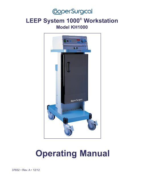
<strong>LEEP</strong> <strong>System</strong> 1000 ® <strong>Workstation</strong><br />
Model KH1000<br />
<strong>Operating</strong> Manual<br />
37652 • Rev. A • 12/12
<strong>LEEP</strong> <strong>System</strong> 1000 ® <strong>Workstation</strong><br />
Model KH1000<br />
Table of Contents<br />
Section Content Page<br />
1. Description.............................................................................................................................. 1<br />
1.1 Introduction .............................................................................................................................. 1<br />
1.2 Smoke Evacuator Description ................................................................................................. 1<br />
1.3 <strong>LEEP</strong> <strong>System</strong> 1000 ® Electrosurgical Generator Description .................................................... 1<br />
1.4 <strong>LEEP</strong> Cart Description ............................................................................................................. 1<br />
2. Unpacking and Assembly...................................................................................................... 2<br />
2.1 Unpacking the <strong>LEEP</strong> Cart (box #1) .......................................................................................... 2<br />
2.2 Unpacking and Installing the Smoke Evacuator (box #2) ........................................................ 3<br />
2.3 Unpacking and Installing the <strong>LEEP</strong> <strong>System</strong> 1000 Electrosurgical Generator (box #3) ........... 3<br />
2.4 Installing the Filters and Tubing to the Smoke Evacuator ....................................................... 4<br />
2.5 Connecting the Smoke Evacuator and <strong>LEEP</strong> <strong>System</strong> 1000 Electrosurgical Generator<br />
together and to the Wall Outlet................................................................................................. 5<br />
2.6 Installing the Foot Pedal Switch on the <strong>LEEP</strong> <strong>System</strong> 1000 Electrosurgical Generator .......... 5<br />
2.7 Installing the Electrodes and Dispersive Patient Plate............................................................. 5<br />
3. <strong>LEEP</strong> <strong>System</strong> 1000 Electrosurgical Generator Features.................................................... 7<br />
4. Front Panel of the <strong>LEEP</strong> <strong>System</strong> 1000 Electrosurgical Generator .................................... 8<br />
5. Professional Use Guide ........................................................................................................ 9<br />
5.1 <strong>LEEP</strong> Cart Use ........................................................................................................................ 9<br />
5.2 Indications ............................................................................................................................... 10<br />
5.3 Contraindications .................................................................................................................... 10<br />
5.4 <strong>LEEP</strong> Procedure and Technique ............................................................................................. 10<br />
5.5 Safety Precautions ................................................................................................................. 10<br />
5.6 Electrosurgical Procedures ..................................................................................................... 11<br />
5.7 Turning on the Smoke Evacuator and <strong>LEEP</strong> <strong>System</strong> 1000 Electrosurgical Generator ........... 11<br />
6. <strong>Operating</strong> the <strong>System</strong> ........................................................................................................... 12<br />
6.1 Setting the Controls and Output Mode.................................................................................... 12<br />
6.2 Guidelines for Power Settings................................................................................................. 13<br />
6.3 Thermal Effects on Tissue Treated with Loop Electrodes ....................................................... 14<br />
7. Electrosurgical Precautions................................................................................................. 14<br />
8. Periodic Safety Checks and Maintenance .......................................................................... 17<br />
8.1 <strong>LEEP</strong> <strong>System</strong> 1000 Electrosurgical Generator ....................................................................... 17<br />
8.2 Smoke Evacuator.................................................................................................................... 17<br />
9. Safety Circuits ....................................................................................................................... 17<br />
10. Practical Suggestions .......................................................................................................... 17<br />
11. Cleaning the <strong>LEEP</strong> <strong>System</strong> 1000 Electrosurgical Generator and Smoke Evacuator...... 18<br />
<strong>LEEP</strong> <strong>System</strong> 1000 ® <strong>Workstation</strong> • <strong>Operating</strong> Manual<br />
i
Table of Contents (continued)<br />
Section Content Page<br />
12. Troubleshooting .................................................................................................................... 18<br />
13. Liability Statement ................................................................................................................ 19<br />
14. Warranty ................................................................................................................................ 19<br />
15. Service and Repair................................................................................................................ 20<br />
16. <strong>LEEP</strong> <strong>System</strong> 1000 Electrosurgical Generator EMC Compliance Information................ 21<br />
17. Specifications........................................................................................................................ 23<br />
17.1 Electrical – <strong>LEEP</strong> <strong>System</strong> 1000 ® <strong>Workstation</strong> ......................................................................... 23<br />
17.2 General Specifications – <strong>LEEP</strong> <strong>System</strong> 1000 Electrosurgical Generator ............................... 24<br />
17.3 Smoke Evacuator.................................................................................................................... 26<br />
17.4 <strong>LEEP</strong> Cart ............................................................................................................................... 26<br />
18. Explanation of Symbols........................................................................................................ 27<br />
ii<br />
<strong>LEEP</strong> <strong>System</strong> 1000 ® <strong>Workstation</strong> • <strong>Operating</strong> Manual
Section 1<br />
Description<br />
1.1 Introduction<br />
Congratulations on owning the <strong>LEEP</strong> <strong>System</strong> 1000 ® <strong>Workstation</strong>, which includes the following components:<br />
<strong>LEEP</strong> <strong>System</strong> 1000 <strong>Workstation</strong>, 110 VAC (Model KH1000)<br />
<strong>LEEP</strong> <strong>System</strong> 1000 ® Electrosurgical Generator<br />
110 VAC<br />
Smoke Evacuator<br />
110 VAC<br />
<strong>LEEP</strong> Cart<br />
Accessories<br />
(filters, tubing, etc.)<br />
Before you can use this equipment, you must assemble the <strong>LEEP</strong> <strong>System</strong> 1000 Electrosurgical<br />
Generator and the Smoke Evacuator onto the <strong>LEEP</strong> Cart. Refer to Section 2 for Unpacking and<br />
Assembly instructions.<br />
1.2 Smoke Evacuator Description<br />
The <strong>CooperSurgical</strong> Smoke Evacuation <strong>System</strong> three-stage air filtration system is used to remove airborne<br />
particulate plume produced during office and surgical procedures and has the following features:<br />
– Low noise level<br />
– Triple filtration of air provides efficiency level for 0.014 microns rated at 99.999%. This includes a<br />
pre-filter, a charcoal filter for odor removal and a final safety filter placed after the charcoal filter<br />
– Adjustable high air flow for effective collection of plume<br />
– Virtually maintenance-free<br />
– Conveniently attaches to the <strong>CooperSurgical</strong> <strong>LEEP</strong> <strong>System</strong> 1000 <strong>Workstation</strong><br />
1.3 <strong>LEEP</strong> <strong>System</strong> 1000 Electrosurgical Generator Description<br />
The Electrosurgical Generator has the following features:<br />
– Isolated power output and LED display located in the front for precise power selection, delivery<br />
and ease of use<br />
– Flush faceplate membrane facilitates operation and cleaning<br />
– Microprocessor-controlled for increased precision, accuracy, reproducibility and safety<br />
– Provides a choice of CUT, BLEND and COAG waveforms to accommodate subtle differences<br />
in technique and electrode performance<br />
– Pneumatic Foot Pedal for maximum safety<br />
– Audible safety features include distinct tones for each operating setting<br />
– Automatic self-test mechanism ensures accurate system operation<br />
– Integrated Smoke Evacuator controls<br />
1.4 <strong>LEEP</strong> Cart Description<br />
Advantages of this style cart:<br />
– Added mobility and functionality for transporting the Electrosurgical Generator and<br />
Smoke Evacuator in one unit<br />
– Designed to work in small exam rooms<br />
– Heavy-duty casters ensure easy mobility<br />
– Convenient interior storage shelves<br />
– Elegant design for modern medical facilities<br />
<strong>LEEP</strong> <strong>System</strong> 1000 ® <strong>Workstation</strong> • <strong>Operating</strong> Manual<br />
1
Section 2<br />
Locate all three product boxes.<br />
Unpacking and Assembly<br />
2.1 Unpacking the <strong>LEEP</strong> Cart (box #1)<br />
When it comes to unpacking the carton that contains the Cart, great care must be taken. The box must be<br />
on its side (following the markings on the carton for which side is up) and the Cart rolled out. Orient the box as<br />
shown in Photo A.<br />
CAUTION: DO NOT PICK THE CART UP OUT OF THE SHIPPING BOX BY ITS HANDLES. THE HANDLES<br />
ARE NOT DESIGNED TO ACCOMMODATE THE FULL WEIGHT OF THE CART.<br />
1. After removing the Cart from the shipping box, lock the front two casters.<br />
2. Install the Smoke Evacuator next.<br />
Photo A<br />
2 <strong>LEEP</strong> <strong>System</strong> 1000 ® <strong>Workstation</strong> • <strong>Operating</strong> Manual
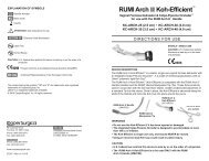
<strong>LEEP</strong> <strong>System</strong> 1000 ® Electrosurgical<br />
Generator Control Panel<br />
<strong>LEEP</strong> Cart<br />
To the outlet<br />
<strong>LEEP</strong> <strong>System</strong> 1000<br />
Electrosurgical Generator<br />
(A)<br />
(B)<br />
Pivot Hinge<br />
Door<br />
Smoke Evacuator<br />
Locking Caster (wheel)<br />
(1 of 2)<br />
Insert two screws in each hinge<br />
Figure 1<br />
2.2 Unpacking and Installing the Smoke Evacuator (box #2)<br />
Required Tools: Phillips Screwdriver<br />
After unpacking the Smoke Evacuator box,<br />
1. Remove the screws on the base of the Cart in preparation for attaching the Smoke Evacuator.<br />
2. Then align the pivot hinges on the Smoke Evacuator with the screw holes on the Cart itself and fasten<br />
the Smoke Evacuator to the Cart. Make sure that the screws are tight, but DO NOT OVERTIGHTEN.<br />
3. Remove the screws on the side of the Smoke Evacuator and then fasten down the bracket of the drop hinge<br />
to the Smoke Evacuator. See Figure 1.<br />
NOTE: The Smoke Evacuator Controls are located at the top front of the <strong>LEEP</strong> Cart for easy access.<br />
4. Install the Electrosurgical Generator next.<br />
2.3 Unpacking and Installing the <strong>LEEP</strong> <strong>System</strong> 1000 ® Electrosurgical Generator (box #3)<br />
After unpacking the Electrosurgical Generator box, align the pins on the bottom of the Electrosurgical Generator<br />
with the corresponding holes located on the top of the Cart. See Figure 1.<br />
Face the Electrosurgical Generator toward the front of the Cart (where the door is) and drop the cord through the<br />
rectangular cutout located at the top of the Cart. Do not hook up this cord until you have installed the filter and<br />
tubing in the Smoke Evacuator.<br />
<strong>LEEP</strong> <strong>System</strong> 1000 ® <strong>Workstation</strong> • <strong>Operating</strong> Manual<br />
3
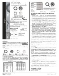
2.4 Installing the Filters and Tubing to the Smoke Evacuator<br />
2.4.1 ULPA Filter Installation<br />
Tilt the Smoke Evacuator forward and insert the large<br />
ULPA Filter Cylinder with the air-flow arrow pointing down.<br />
(See Photo B)<br />
Photo B<br />
2.4.2 Installing the Pre-Filter<br />
Insert a clean, disposable Pre-Filter onto the ULPA Filter Cylinder.<br />
(See Photo C). Be sure this device is firmly seated.<br />
Photo C<br />
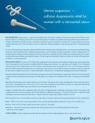
2.4.3 Connecting the Tubing<br />
There are two tubing hookup options:<br />
a) For procedures requiring close-proximity plume removal (i.e., Vaginal Speculum)<br />
b) For procedures requiring open-area plume removal (i.e., external lesions)<br />
For procedures requiring close-proximity plume removal (i.e., Vaginal Speculum)<br />
Assemble the ⅜" Reducer (REF 6083) onto the port on the<br />
disposable Pre-Filter (REF 6081) top with a slight twisting<br />
motion. Attach one end of an appropriate length of ⅜" ID<br />
Evacuation Tubing (REF 6084) to the Reducer connector and<br />
direct the other end to the patient and any appropriate device<br />
being used, such as a Vaginal Speculum equipped with a<br />
Smoke Evacuation Adapter. (See Photo D)<br />
Photo D<br />
For procedures requiring open-area plume removal (i.e., external lesions)<br />
Assemble the sterile, disposable 1¼" ID Evacuation Tubing (REF 6085) directly into the top of<br />
the Pre-Filter. Position the opposite end over the site to be treated.<br />
4 <strong>LEEP</strong> <strong>System</strong> 1000 ® <strong>Workstation</strong> • <strong>Operating</strong> Manual
2.5 Connecting the Smoke Evacuator and <strong>LEEP</strong> <strong>System</strong> 1000 ® Electrosurgical Generator<br />
together and to the Wall Outlet<br />
1. Plug in the cord running from the Electrosurgical Generator to the receptacle at the back of the<br />
Smoke Evacuator [refer to (A) in Figure 1].<br />
2. Make sure both On/Off Switches on the Electrosurgical Generator panel are in the OFF position.<br />
Refer to 1 and 12 in Figure 2. Next, attach the power cord to the receptacle at the back of the Electrosurgical<br />
Generator and then into a hospital-grade grounded wall outlet to obtain power [refer to (B) in Figure 1].<br />
2.6 Installing the Foot Pedal Switch on the <strong>LEEP</strong> <strong>System</strong> 1000 Electrosurgical Generator<br />
Connect the Foot Pedal Switch to the socket 2 , shown in Figure 2, without activating the Foot Pedal, and<br />
tighten the threaded plug. This is an air (pneumatic) operated control. There is no electric current, offering<br />
maximum safety.<br />
5 6 7 10<br />
1 2<br />
8<br />
9<br />
3<br />
4<br />
11<br />
12<br />
Figure 2<br />
2.7 Installing the Electrodes and Dispersive Patient Plate<br />
2.7.1 Placement of the Electrode<br />
• Connect the active Electrode Handpiece to the socket 3<br />
electrode of choice in the Handpiece.<br />
, shown in Figure 2, and tighten the<br />
2.7.2 Placement of the Patient Plate or Dispersive Electrode<br />
When using an electrosurgical system, it is very important that all the current delivered to the<br />
patient returns correctly to the Electrosurgical Generator via the Dispersive Patient Plate only.<br />
• Connect Dispersive Patient Plate to the socket 4 . Refer to Figure 2.<br />
• The patient must be positioned correctly on the operating table. The patient and operator must<br />
not come in contact with any metal conductive surfaces.<br />
• The Patient Plate must securely contact a vascular area close to the operating site. For a<br />
gynecology procedure the preferred sites are the patient's thigh (disposable adhesive pads) or<br />
under the patient's buttocks (reusable metal plate). The contact area must be clean, free of<br />
body lotions, shaved, and massaged for good circulation. The contact area of the Patient Plate<br />
must be maximized and frequently checked for uniform contact during the procedure, especially<br />
if the patient has moved or if liquids have contacted the Patient Plate. A CONDUCTIVE GEL IS<br />
RECOMMENDED. The Patient Plate MUST NEVER be placed so as to allow the patient's heart<br />
to be in the pathway from the active electrode.<br />
• Power delivery to the operative site may be decreased appreciably if alternate pathways exist;<br />
for example, through the metal operating table, crossed Handpiece/Patient Plate Cables, etc.<br />
<strong>LEEP</strong> <strong>System</strong> 1000 ® <strong>Workstation</strong> • <strong>Operating</strong> Manual<br />
5
Figures 3 through 5 show the proper and improper ways of hooking up and using the various electrodes and<br />
pads on the patient.<br />
PROPER<br />
Electrosurgical<br />
Generator<br />
RF current through<br />
patient to return pad<br />
Active Electrode<br />
Patient<br />
Grounded<br />
Metal Case<br />
Two conductor patient<br />
electrode continuity<br />
monitor<br />
Patient return pad<br />
(Thigh)<br />
Patient may be grounded<br />
Figure 3<br />
IMPROPER<br />
Electrosurgical Generator<br />
Burn occurs at small<br />
grounded contact<br />
RF<br />
EKG<br />
Isolated<br />
ESU<br />
Surgeon touches electrode<br />
to grounded object<br />
RF current flows from ground<br />
through EKG pad, through<br />
patient to return pad<br />
Figure 4<br />
IMPROPER<br />
Electrosurgical<br />
Generator<br />
RF current flows from<br />
electrode<br />
Burn occurs at small<br />
grounded contact<br />
RF<br />
EKG<br />
Isolated or<br />
grounded ESU<br />
Patient return pad touches<br />
grounded table<br />
RF current returns to patient<br />
return pad via ground path<br />
Figure 5<br />
6 <strong>LEEP</strong> <strong>System</strong> 1000 ® <strong>Workstation</strong> • <strong>Operating</strong> Manual
Section 3<br />
<strong>LEEP</strong> <strong>System</strong> 1000 ® Electrosurgical Generator Features<br />
• Microprocessor-controlled for increased precision, accuracy, repeatability and safety<br />
• Adequate power for all <strong>LEEP</strong> monopolar electrosurgical procedures<br />
• Accurate selection of discrete power levels<br />
• Digital display of output power levels<br />
• Choice of radio-frequency waveforms including CUT, BLEND and COAG to accommodate subtle<br />
differences in technique and accessory performance<br />
• Patient Plate continuity monitoring with audible alarm<br />
• Distinct audible tones for CUT/BLEND modes and COAG mode with associated MODE light<br />
• Fully regulated isolated output power<br />
• Meets or exceeds IEC 601-2-2, second edition<br />
• Non-electric pneumatic Foot Pedal to maximize safety<br />
• Choice of reusable or disposable Patient Plate<br />
• Choice of reusable or disposable Handpiece<br />
• Choice of reusable or disposable electrodes<br />
• Output power safety audible alarm with automatic power shut-off<br />
• Class 1, type BF, protected for use with defibrillator<br />
• Membrane switching to maximize cleanliness and ease of use<br />
<strong>LEEP</strong> <strong>System</strong> 1000 ® <strong>Workstation</strong> • <strong>Operating</strong> Manual<br />
7
Section 4 Front Panel of the <strong>LEEP</strong> <strong>System</strong> 1000 ®<br />
Electrosurgical Generator<br />
(Cart not shown)<br />
5<br />
6<br />
7<br />
10<br />
(Colored, numbered boxes are also<br />
located later in this manual.)<br />
1 2<br />
8 9<br />
3<br />
4<br />
11<br />
12<br />
Figure 6<br />
<strong>Workstation</strong> Controls<br />
1. Main Switch (On/Off)<br />
2. Socket for pedal switch<br />
3. Socket for active electrodes<br />
4. Socket for neutral electrode<br />
5. Warning light of neutral electrode alarm (red)<br />
6. Coagulation light (blue)<br />
7. Pure cut and blend light (yellow)<br />
8. Mode control:<br />
Pure Cut<br />
Blend Cut<br />
Coag<br />
9. Power control<br />
10. Display<br />
Smoke Evacuator Controls<br />
11. Suction Control Knob<br />
12. Smoke Evacuator Power Switch (On/Off)<br />
Symbols on the <strong>LEEP</strong> <strong>System</strong> 1000 Electrosurgical Generator<br />
Classification I Type BF protected against defibrillator effects<br />
Floating output circuit (Applied Part)<br />
Cautions – consult this manual for safety precautions<br />
Pedal connection<br />
Active handle connection<br />
Patient Plate connection<br />
High voltage<br />
10 °C<br />
45 °C<br />
Temperature limitation<br />
8 <strong>LEEP</strong> <strong>System</strong> 1000 ® <strong>Workstation</strong> • <strong>Operating</strong> Manual
IMPORTANT<br />
The user of the <strong>LEEP</strong> <strong>System</strong> 1000 ® Electrosurgical Generator should be thoroughly trained in the<br />
techniques of Loop Electrosurgical Excision Procedures. This equipment has been designed for use<br />
with <strong>LEEP</strong> Electrosurgical Accessories. DO NOT use this equipment for any purpose other than that<br />
for which it has been designed. See warnings and caution statements throughout this manual.<br />
Section 5<br />
Professional Use Guide<br />
This manual contains information about the proper procedures for inspecting and preparing the Electrosurgical<br />
Generator before its use, and for its care and storage after use.<br />
This manual does not describe how an actual procedure is to be performed, nor is it meant to teach a<br />
beginner the proper technique or any of the medical considerations regarding the use of this equipment.<br />
<strong>CooperSurgical</strong> recommends that the prospective user obtain appropriate training before using this<br />
equipment, as improper use could be potentially hazardous to the patient and the user.<br />
This device SHOULD NOT be used without proper training.<br />
Training in the use of electrosurgical equipment should include:<br />
1. A review of the published literature regarding the procedure of interest<br />
2. A review of the Loop Electrosurgical Excision Procedure (<strong>LEEP</strong>) Syllabus available<br />
from <strong>CooperSurgical</strong><br />
3. Attendance at a course or courses offered by physicians experienced with the Loop<br />
Electrosurgical Excision Procedure<br />
4. Hands-on preceptor training from an experienced practitioner<br />
Read this entire manual carefully to become familiar with each of the controls and features before<br />
making any attempt to use the equipment clinically.<br />
Instructions contained in the operating manuals of any equipment to be used in conjunction with this<br />
equipment must be followed to avoid any possible hazard from incompatibility.<br />
Failure to thoroughly understand and follow the instructions given in this manual may result in serious injury to<br />
the patient and/or the operator. Failure to follow the instructions given in this manual may result in damage to<br />
or malfunction of this equipment.<br />
No long-term follow-up studies with this device have been performed as to recurrence rates. The effects of<br />
Loop Electrosurgical Excision Procedure on pregnancy outcome are not known.<br />
SAFETY PRECAUTIONS MUST ALWAYS BE EXERCISED WHEN USING ELECTRICAL EQUIPMENT TO<br />
PREVENT OPERATOR/PATIENT SHOCK, FIRE HAZARD AND EQUIPMENT DAMAGE.<br />
CAUTION: U.S. Federal law restricts this device to sale by or on the order of a physician. This device<br />
SHOULD NOT be used without proper training and preceptorship.<br />
If any questions arise regarding the information contained in this manual, the operation or safety of the<br />
equipment or service, please contact <strong>CooperSurgical</strong>.<br />
5.1 <strong>LEEP</strong> Cart Use<br />
VERY IMPORTANT: The <strong>LEEP</strong> <strong>System</strong> 1000 ® <strong>Workstation</strong> must only be moved by grasping and holding<br />
firmly onto the Cart Handles to assure the Cart does not tip over.<br />
The Cart must only be pushed or pulled using the handles on the front or back of the Cart to ensure<br />
stability during transportation.<br />
<strong>LEEP</strong> <strong>System</strong> 1000 ® <strong>Workstation</strong> • <strong>Operating</strong> Manual<br />
9
5.2 Indications<br />
The <strong>LEEP</strong> procedure is indicated in the diagnosis and treatment of some Cervical Intraepithelial<br />
Neoplasia (CIN) in patients where there is:<br />
• Cytological or colposcopic suspicion of CIN 2 or worse (including micro-invasion)<br />
• Persistent CIN 1 (of more than 12 months duration)<br />
• CIN 1 where the likelihood of follow-up is low or when the patient requests treatment<br />
• A suspicion (cytological or colposcopic) of a glandular intraepithelial abnormality<br />
• A disparity between the cytological and colposcopic diagnoses<br />
• External anogenital lesion<br />
• Large vaginal intraepithelial neoplastic (VAIN) lesions<br />
• Cervical conization indications<br />
5.3 Contraindications<br />
The following are typical contraindications for performing the <strong>LEEP</strong> procedure. It is imperative that the<br />
physician carefully weigh the risks and benefits of treatment versus non-treatment in contraindicated<br />
patients:<br />
• Pregnancy<br />
• Gross invasive carcinoma of the cervix<br />
• A bleeding disorder<br />
• Acute or active inflammation of the cervix, endometrium, fallopian tube, ovary or peritoneum<br />
(cervicitis, endometritis, tubo-ovarian inflammatory disease or pelvic inflammatory disease)<br />
• “Positive” endocervical curettage or a lesion in which the endocervical limit cannot be visualized<br />
colposcopically<br />
• Less than three months postpartum<br />
• Equivocal cervical abnormality<br />
5.4 <strong>LEEP</strong> Procedure and Technique<br />
It is recommended that the patient be provided with a brief description of the procedure and the equipment<br />
that will be used (ACOG, <strong>CooperSurgical</strong> and other professional organizations and equipment manufacturers<br />
have produced patient information brochures on the <strong>LEEP</strong> procedure that address many of the questions and<br />
concerns that your patients may have regarding the procedure).<br />
5.5 Safety Precautions<br />
1. This equipment should only be used by a thoroughly trained physician in an adequately equipped<br />
medical facility.<br />
2. Replacement accessories and patient return pads should be kept on hand since defective active<br />
accessory or patient return pads can result in substandard performance of this equipment.<br />
3. This equipment should only be connected to a properly grounded receptacle. NEVER use an adapter<br />
that defeats the ground of the built-in three (3) prong plug.<br />
4. Care must be exercised when handling liquids around electrical equipment. DO NOT attempt to<br />
operate this equipment if liquids have spilled on the Electrosurgical Generator. DO NOT use<br />
flammable liquids around electrical equipment.<br />
5. This equipment should never be used in conjunction with other equipment for which safety against<br />
leakage current has not been established.<br />
10 <strong>LEEP</strong> <strong>System</strong> 1000 ® <strong>Workstation</strong> • <strong>Operating</strong> Manual
6. When this equipment is operated:<br />
a. A Patient Return Pad (dispersive pad) of adequate surface area MUST be properly attached to<br />
the patient or the risk of accidental burns will exist.<br />
b. The Patient Return Pad (dispersive pad) should be placed as close as possible to the site of<br />
use of the active accessory – but MUST NEVER be placed so as to allow the patient’s heart to<br />
be in the pathway from the active accessory to the return electrode!<br />
7. The user should thoroughly understand the principles and use of radio frequency (RF) current before<br />
using this equipment. This understanding is essential to avoid the hazard of shocks or burns to the<br />
user and/or the patient.<br />
8. The instructions for use described in this manual must be followed; otherwise, compromised safety,<br />
malfunction, injury to the operator and/or patient, or costly damage to the Electrosurgical Generator<br />
may occur.<br />
9. There are no user-serviceable parts within the housing. Repairs to this equipment should only be<br />
performed by authorized <strong>CooperSurgical</strong> service personnel. For service information, please contact<br />
<strong>CooperSurgical</strong> (refer to Section 15).<br />
5.6 Electrosurgical Procedures<br />
This section provides only general information about the use of electrosurgical devices. Only the user<br />
can evaluate the clinical factors involved with each patient and determine if the use of this equipment is<br />
indicated. The user must then decide on the specific technique and procedure that will accomplish the<br />
desired clinical effect.<br />
WARNING<br />
Electrosurgical generators are designed to allow the controlled destruction of tissue and are<br />
inherently dangerous if operated improperly.<br />
REPORTED PROBLEMS DUE TO IMPROPER OPERATION DURING ELECTROSURGICAL<br />
PROCEDURES HAVE INCLUDED:<br />
• Inadvertent activation with resultant tissue damage at the wrong site and/or<br />
equipment damage<br />
• Alternate current pathways resulting in burns where the patient or physician or assistant<br />
is in contact with exposed metal<br />
• Explosions caused by electrosurgical sparking in a flammable gas mixture (i.e., explosive<br />
anesthetic gases and the inappropriate use of alcohol and other flammable liquids)<br />
• Perforation and massive hemorrhage<br />
A proper patient return pad pathway is extremely important during any monopolar<br />
electrosurgical procedure. Every effort must be made to ensure that, throughout the<br />
electrosurgical procedure, an adequate surface area is provided and remains in proper<br />
contact with the patient to reduce the current density below a level that might cause<br />
inadvertent tissue damage where the patient return pad has been applied.<br />
5.7 Turning on the Smoke Evacuator and <strong>LEEP</strong> <strong>System</strong> 1000 ® Electrosurgical Generator<br />
NOTE: Numbers in blue boxes refer to those component parts shown in Figure 6.<br />
Push the POWER switch 12 , located under the Electrosurgical Generator (for the Smoke Evacuator), to<br />
the “On” position. This will start the Smoke Evacuator.<br />
Turn ON the Electrosurgical Generator using the power switch 1 . The Electrosurgical Generator<br />
automatically performs a SELF-TEST that checks RAM memory, EPROM memory, supply voltage, signal<br />
modulation and the following displays: function selector green lights, digital display, cut and coagulant yellow<br />
light, coagulation blue light, and the audible signal. When the Electrosurgical Generator passes SELF-TEST,<br />
the display will show current software revision, i.e., r2A, r2B, for several seconds, then will go blank.<br />
<strong>LEEP</strong> <strong>System</strong> 1000 ® <strong>Workstation</strong> • <strong>Operating</strong> Manual<br />
11
Section 6<br />
<strong>Operating</strong> the <strong>System</strong><br />
NOTE: Numbers in blue boxes refer to those component parts shown in Figure 6.<br />
CUT MODE: Control 8 sets the cut mode power output. The Electrosurgical Generator<br />
automatically powers up to cut mode when turned ON. The top LED lights on the<br />
Selector 8 and Control 9 sets the power.<br />
BLEND MODE: Control 8 selects blend mode (center LED) and Control 9 sets the power.<br />
COAGULATION MODE: Control 8 selects coagulation mode (bottom LED) and Control 9 sets<br />
the power.<br />
Power settings are stored when the system is ON and will appear automatically on the Display 10 according<br />
to the selection of power mode by the Control 8 during the procedure.<br />
Power may be changed at any time during the operation, except when the Electrosurgical Generator is<br />
activated by the Foot Pedal.<br />
At the end of the procedure turn the Electrosurgical Generator OFF, and safely store the equipment and<br />
accessories. Power will reset to zero.<br />
6.1 Setting the Controls and Output Mode<br />
6.1.1 Using the Smoke Evacuator and Disposing the Filters<br />
Adjust the Suction Control Knob 11 to the desired level.<br />
At the completion of each procedure activate the system to ensure safe particle containment.<br />
Using gloves and a mask, remove the Pre-Filter, the Reducer and the used section of Suction<br />
Tubing and discard into an infectious waste receptacle (See the CAUTIONS box). The Smoke<br />
Evacuator should be stored with a new Pre-Filter and Reducer in place on the ULPA Filter.<br />
NOTE: The expected life of the ULPA Filter is three to six months, depending on usage. It<br />
must be discarded into an infectious waste receptacle if plume odor is detected or the<br />
suction is diminished.<br />
CAUTIONS<br />
This device produces a strong vacuum force, and care should be exercised to ensure that<br />
the suction control and the position of the inlet end of the Suction Tubing are adjusted<br />
properly to prevent injury to the patient or inadvertent damage to surgical materials.<br />
The materials removed from the plume by this device are potentially hazardous. Handle<br />
according to 29 CFR 1910.1030 and OSHA 3127.1992 (Occupational Exposure to Blood<br />
Borne Pathogens) guidelines.<br />
To prevent a fire or explosion hazard, do not use the system in the presence of<br />
flammable or potentially flammable materials.<br />
Do not allow fluid to be pulled into the system.<br />
To prevent premature failure of the ULPA Filter Cylinder, do not operate this device<br />
without a disposable Pre-Filter in place.<br />
6.1.2 Electrosurgical Tissue Effect<br />
Delivery of continuous sinusoid waveform currents through a small electrode at appropriate power<br />
levels can cause rapid heating of the intracellular fluids in the cells in close proximity to the<br />
electrode, turning these fluids to steam. The significant increase in volume (approximately five<br />
times) causes cellular structure to rupture, creating the clinical effect of “CUT”, with little or no<br />
hemostatic effect along the margin of the divided tissue. Delivery of short-duration pulses of<br />
RF currents through a small electrode at appropriate power levels can cause heating of intracellular<br />
fluids at a more gradual pace. This allows evaporation of these fluids without rupturing the cellular<br />
structure, creating the clinical effect of desiccation, or “COAG”, without the division of tissue.<br />
12 <strong>LEEP</strong> <strong>System</strong> 1000 ® <strong>Workstation</strong> • <strong>Operating</strong> Manual
By varying the pulse to an intermediate duration, it is possible to get a clinical effect that combines,<br />
or “blends”, the clinical characteristics of CUT and COAG, yielding the effect referred to as<br />
“BLEND”, where tissue is divided with a desirable amount of hemostatis along the margins of the<br />
divided tissue.<br />
The electrosurgical effect may vary throughout the procedure, requiring the operator to adjust the<br />
relative power setting of the Electrosurgical Generator.<br />
6.1.3 Select the Output Mode (i.e., “CUT”, “BLEND” or “COAG”, by Pushing the Corresponding Buttons<br />
Output Mode Waveform Description<br />
General Effect<br />
CUT Continuous 450 kHz sinusoid Cutting without Hemostatis<br />
with minimal modulation<br />
BLEND Interrupted 450 kHz sinusoid Cutting with minimal<br />
intermediate-duty cycle<br />
Hemostatis<br />
COAG Bursts of 450 kHz sinusoid Coagulation without Cutting<br />
short-duty cycle<br />
6.1.4 Set the level of Output Power (confirmed on the digital display) by using the Output Power<br />
Selector Buttons as Desired<br />
WARNING<br />
The degree and speed of electrosurgical effect is largely dependent on Current Density<br />
at the point of contact of the active electrode. Loop electrosurgical excision procedure<br />
electrodes from other manufacturers may vary in the diameter thickness, size and<br />
configuration of the cutting wire. This may result in SIGNIFICANT changes in the<br />
electrosurgical effect at a given output power level setting. The use of <strong>CooperSurgical</strong><br />
<strong>LEEP</strong> Electrodes is recommended.<br />
6.2 Guidelines for Power Settings<br />
The following guidelines for power settings may vary due to the technique, clinical circumstances,<br />
accessory style, cutting wire diameter, size, configuration and user preference.<br />
Recommended Power Settings (Watts) for the <strong>CooperSurgical</strong> <strong>LEEP</strong> <strong>System</strong> 1000 ® Electrodes<br />
Style<br />
Loop Width (cm)<br />
Ball<br />
Needle<br />
Electrodes<br />
Electrodes<br />
1.0 1.5 2.0 Macro Micro<br />
CUT* — — — — — 14–24<br />
BLEND 22–36 30–40 34–46 — — —<br />
COAG — — — 40–56 + 30–36 —<br />
NOTE<br />
* If the cut mode is desired,<br />
use the recommended<br />
settings for the blend mode.<br />
+ The power setting can be<br />
increased beyond 56 to<br />
coagulate any bleeding points<br />
as required.<br />
Wattage Suggestions for Fischer Cone Biopsy Excisor<br />
Part<br />
Number<br />
Size<br />
Wattage Rating<br />
Part<br />
Number<br />
The above settings are for reference only and can be varied based on specific situations and the<br />
experience of the operator.<br />
Size<br />
Wattage Rating<br />
900-150 Small 30-35 Watts 900-152 Large 45-50 Watts<br />
900-151 Medium 40-45 Watts 900-157 Small Wide 40-45 Watts<br />
900-154<br />
900-155<br />
Medium<br />
Extended<br />
Large<br />
Shallow<br />
40-45 Watts 900-158<br />
40-45 Watts<br />
Small Wide<br />
Extended<br />
40-45 Watts<br />
<strong>LEEP</strong> <strong>System</strong> 1000 ® <strong>Workstation</strong> • <strong>Operating</strong> Manual<br />
13
REMEMBER, THIS IS NOT AN ATTEMPT TO TEACH ELECTROSURGICAL TECHNIQUE.<br />
The practitioner who lacks experience should not attempt the procedures described below based solely<br />
on this information; instead, the skills required should be acquired in the time-honored preceptor manner.<br />
Call <strong>CooperSurgical</strong> for information on courses that offer instruction on the proper use of electrosurgical<br />
generators and accessories.<br />
NOTE: The best initial effect is accomplished with the cutting wire in only light contact with tissue. Light<br />
pressure may cause desiccation of the tissue and will delay the start of the cutting effect.<br />
If the use of other output modes is anticipated, repeat steps in Sections 6.1.3, 6.1.4 and 6.2 as desired.<br />
The output power level settings selected for each output mode will be retained as long as the Electrosurgical<br />
Generator remains ON.<br />
IMPORTANT<br />
The initial use of any electrosurgical generator always involves some degree of “trial and error”.<br />
This is true even when only changing from numbered dials to digital display models within the<br />
same manufacturer’s product line. As with any other therapeutic device, it is very helpful to<br />
experiment IN VITRO or on animal sample tissue before using any electrosurgical generator<br />
or methods which are not familiar.<br />
The microprocessor control system of the Electrosurgical Generator was developed specifically<br />
to provide the best possible performance for loop electrosurgical excision procedures. By<br />
exhibiting patience and following the guidelines offered, the practitioner should easily<br />
become familiar with the performance characteristics of the <strong>LEEP</strong> <strong>System</strong> 1000 ®<br />
Electrosurgical Generator.<br />
6.3 Thermal Effects on Tissue Treated with Loop Electrodes<br />
Thermal effects on tissue specimens may include:<br />
1) Thermal coagulation injury of the cervix, up to one-third the thickness of normal epithelium of the cervix;<br />
2) Fragmentation of squamous epithelium of the cervix attributable to long exposure periods along the<br />
excision site that allows heat to dissipate laterally;<br />
3) Partial coagulation of the endocervical epithelium because of lateral radiation of heat. Therefore, the Loop<br />
Electrosurgical Excision Procedure (<strong>LEEP</strong>) may produce thermal effects at the periphery of the excised<br />
tissue and may make histopathologic interpretation difficult or impossible and therefore, may not allow<br />
accurate diagnosis and may obscure the need for further treatment.<br />
Section 7<br />
Electrosurgical Precautions<br />
The safety and effectiveness of electrosurgery is dependent, to a large degree, upon the skill of the<br />
user/operator. It is important that the user/operator read, understand and follow the operating instructions<br />
supplied with the <strong>CooperSurgical</strong> <strong>LEEP</strong> <strong>System</strong> 1000 ® Electrosurgical Generator and thoroughly understand<br />
the principles and use of radio-frequency (RF) electrosurgical systems.<br />
WARNING: Electrosurgery uses radio-frequency energy to cut and coagulate tissue. Because of the sparking<br />
and heat associated with electrosurgery, do not use with flammable anesthetics or other flammable gases,<br />
near flammable fluids or objects, or with oxidizing agents.<br />
• DO NOT use electrosurgery in the presence of flammable gases, flammable liquids or flammable<br />
objects in oxygen-enriched atmospheres, in nitrous oxide (N 2 O) atmosphere or in the presence of<br />
other oxidizing agents.<br />
• Prevent accumulation of oxygen, nitrous oxide (N 2 O) and flammable gases under surgical drapes or<br />
within the area where electrosurgery is performed; moreover, avoid such accumulation in cases of<br />
thorax or head operations unless safely aspirated.<br />
• Verify that all oxygen connections are leak-free before and during the use of electrosurgery.<br />
• DO NOT use electrosurgery in the presence of naturally occurring flammable gases which may<br />
accumulate in body cavities such as the bowel.<br />
14 <strong>LEEP</strong> <strong>System</strong> 1000 ® <strong>Workstation</strong> • <strong>Operating</strong> Manual
• DO NOT use electrosurgery in the presence of flammable liquids, such as skin-prepping agents.<br />
Avoid pooling of flammable liquids near the electrosurgery site or in human body cavities such as the<br />
umbilicus or vagina.<br />
• DO NOT place the electrosurgery active electrode near or in contact with flammable materials, such<br />
as cotton, wool or gauze. The active electrode is hot from use and can cause fire.<br />
• It is possible that the radio frequency can interfere with the electronic circuitry in pacemakers.<br />
To reduce the risk, locate the patient-return electrode as close as possible to the treatment site and<br />
ensure that the current path between the surgical site and the patient-return electrode is as far<br />
removed from the heart as possible. For the gynecology procedures locate the patient-return<br />
electrode on the patient's upper thigh or under the buttocks. Always monitor pacemaker patients<br />
during surgery. In case of doubt ask the pacemaker manufacturer and/or cardiology department.<br />
• In case of loss of power, turn the system off.<br />
• The possibility exists that the radio frequency can interfere with other medical equipment when the<br />
electrosurgical system is operating. To reduce the interference, physically separate the device, utilize<br />
different electrical outlets that are hospital-grounded, do not allow cables to come in contact with each<br />
other, and utilize shielded devices where possible.<br />
• The fixed output power level should be adjusted to the lowest power setting that will successfully<br />
complete the procedure. Refer to the following recommended power settings for the <strong>CooperSurgical</strong><br />
<strong>LEEP</strong> <strong>System</strong> 1000 ® Electrodes.<br />
Recommended Power Settings (Watts) for the <strong>CooperSurgical</strong> <strong>LEEP</strong> <strong>System</strong> 1000 ® Electrodes<br />
Style<br />
Loop Width (cm)<br />
Ball<br />
Needle<br />
Electrodes<br />
Electrodes<br />
1.0 1.5 2.0 Macro Micro<br />
CUT* — — — — — 14–24<br />
BLEND 22–36 30–40 34–46 — — —<br />
COAG — — — 40–56 + 30–36 —<br />
NOTE<br />
* If the cut mode is desired,<br />
use the recommended<br />
settings for the blend mode.<br />
+ The power setting can be<br />
increased beyond 56 to<br />
coagulate any bleeding points<br />
as required.<br />
Wattage Suggestions for Fischer Cone Biopsy Excisor<br />
Part<br />
Number<br />
Size<br />
Wattage Rating<br />
Part<br />
Number<br />
The above settings are for reference only and can be varied based on specific situations and the experience<br />
of the operator.<br />
• Skin to skin contact, for instance between the patient's arm and body, should be avoided by the<br />
placement of an appropriate separating device such as two to three inches of dry gauze. This will<br />
reduce the potential for alternate site burns.<br />
• If monitoring, stimulation, imaging or similar devices are used simultaneously with electrosurgery,<br />
the monitoring electrodes must be placed as far as possible from the electrosurgery site and the<br />
patient-return electrode. Position the patient-return electrode close to the electrosurgery site, for<br />
example, on the thigh when treating the cervix. NOTE: Monitoring needle electrodes are not<br />
recommended.<br />
Size<br />
Wattage Rating<br />
900-150 Small 30-35 Watts 900-152 Large 45-50 Watts<br />
900-151 Medium 40-45 Watts 900-157 Small Wide 40-45 Watts<br />
900-154<br />
900-155<br />
Medium<br />
Extended<br />
Large<br />
Shallow<br />
40-45 Watts 900-158<br />
40-45 Watts<br />
Small Wide<br />
Extended<br />
40-45 Watts<br />
<strong>LEEP</strong> <strong>System</strong> 1000 ® <strong>Workstation</strong> • <strong>Operating</strong> Manual<br />
15
• The electrical cord of the Electrosurgical Generator should be connected to a properly grounded<br />
receptacle. Extension cords and/or adapter plugs should not be used.<br />
• The connecting cables to the electrosurgery electrodes should be placed so that they do not come in<br />
contact with the patient, or with other cables, or cross each other.<br />
• Remove any metal items from the patient: for example, rings, chains, etc.<br />
• Use accessories supplied by <strong>CooperSurgical</strong>; they are specifically designed for the<br />
<strong>LEEP</strong> <strong>System</strong> 1000 <strong>Workstation</strong>.<br />
• Do not use old or worn accessories.<br />
• Avoid High Frequency output settings where the Maximum Output Voltage may exceed the Rated<br />
Accessory Voltage.<br />
• For surgical procedure where the High Frequency current could flow through parts of the body<br />
having a small cross-sectional area, the use of Bipolar techniques may be desirable in order to avoid<br />
unwanted tissue damage.<br />
• Apparent low output or failure of the High Frequency surgical equipment to function correctly at<br />
normal operating settings may indicate faulty application of the Neutral Electrode or poor contact in<br />
its connections. In this case, the application of the Neutral Electrode and its connections should be<br />
checked before selecting a higher output power.<br />
• Regularly inspect the accessories, including the electrode cables and any endoscopically used<br />
accessories, for possible damage.<br />
• Failure of the High Frequency Surgical Equipment could result in an unintended increase of<br />
output power.<br />
Accessory Precautions<br />
• Rated Accessory Voltages should be determined as flows using the Maximum Output Voltage for each<br />
High Frequency Surgical Mode:<br />
> For situations where the MAXIMUM OUTPUT VOLTAGE is less than or equal to 1600V, ASSOCIATED<br />
EQUIPMENT and ACTIVE ACCESSORIES should be selected that have a RATED ACCESSORY<br />
VOLTAGE equal to or greater than the MAXIMUM OUTPUT VOLTAGE.<br />
> ASSOCIATED EQUIPMENT and ACTIVE accessories should be selected with RATED ACCESSORY<br />
VOLTAGE ≥ MAXIMUM OUTPUT VOLTAGE when the smaller variable y [see below] or the number 6<br />
is ≤ CREST FACTOR for that High Frequency SURGICAL MODE.<br />
> When MAXIMUM OUTPUT VOLTAGE (U max ) is > 1600V, and the CREST FACTOR is < the variable y<br />
calculated below, indicating that any ASSOCIATED EQUIPMENT and ACTIVE ACCESSORIES used<br />
with such mode or setting must be rated to withstand the combination of actual voltage and<br />
CREST FACTOR.<br />
y =<br />
U max<br />
– 400 [volts]<br />
600 [volts]<br />
• Neutral Electrode Patient Return Pad requirements:<br />
» Adult Single Dispersive Electrode Pad<br />
» Foam pad with adhesive backing<br />
» 2-conductor wire connection for<br />
continuity monitoring<br />
• ESU Pencil requirements:<br />
» Single-Use<br />
» Footswitch Activated<br />
» Single-Use only<br />
» 19-square inch gel surface area minimum<br />
» Crimped wire Electrosurgical Generator Connector<br />
» IEC 60601-2-2 Compliant<br />
16 <strong>LEEP</strong> <strong>System</strong> 1000 ® <strong>Workstation</strong> • <strong>Operating</strong> Manual
Section 8<br />
Periodic Safety Checks and Maintenance<br />
8.1 <strong>LEEP</strong> <strong>System</strong> 1000 ® Electrosurgical Generator<br />
The following safety checks should be performed at least every 24 months by a qualified person who has<br />
adequate training, knowledge and practical experience to perform these tests.<br />
• Inspect the equipment and accessories for mechanical and functional damage<br />
• Inspect the relevant safety labels for legibility<br />
• Inspect the fuse to verify compliance with rated current and breaking characteristics<br />
• Inspect acoustical and visual alarms/displays<br />
• Verify that the device functions properly as described in the Directions for Use<br />
• Verify that the device shuts down the applied part circuit if the neutral electrode is disconnected<br />
• Test the protection earth resistance according to IEC 601-1/1988: Limit 0.2 ohm<br />
• Check that the output power is within tolerance versus the output control setting at a specified<br />
load resistance<br />
• Check the power output at full and half setting of the output control over the range of load resistance<br />
as specified in the instructions for use (max. deviation is ± 20%)<br />
• Test the enclosure leakage current according to IEC 601-1/1988: Limit 100µA<br />
• Test the leakage current according to IEC 601-1/1988: Limit 100µA (BF)<br />
• Test the patient leakage current under single fault condition with main voltage on the applied part<br />
according to IEC 601-1/1988: Limit: 5mA (BF)<br />
The leakage current should never exceed the limit. The data should be recorded in an equipment log. If the<br />
device is not functioning properly or fails any of the above tests, the device must be repaired.<br />
8.2 Smoke Evacuator<br />
No maintenance is required during normal operation other than ensuring that ample space is<br />
maintained around the Smoke Evacuator to allow for free air flow and adequate cooling.<br />
Section 9<br />
Safety Circuits<br />
The Electrosurgical Generator is equipped with two safety circuits. The first one checks the Dispersive Patient<br />
Plate connection. The second one turns off the power in case of an internal failure. When activating the<br />
Electrosurgical Generator by the Foot Pedal, a power delivery higher than the one selected will stop<br />
power delivery and at the same time give an audible signal similar to the Patient Plate alarm, but at a<br />
higher frequency.<br />
Section 10 Practical Suggestions<br />
To optimize the performance when using an electrosurgical unit, the active electrode must be kept clean and<br />
use the lowest possible power setting required. Some sparks or superficial carbonization of the tissue may<br />
occur and the delivered power may decrease as a result of the electrical insulation caused by the<br />
tissue charring.<br />
Too high of a power setting results in a shorter surgical procedure, but may cause discharges and/or<br />
superficial carbonization, sparking, arcs, etc.<br />
<strong>LEEP</strong> <strong>System</strong> 1000 ® <strong>Workstation</strong> • <strong>Operating</strong> Manual<br />
17
Section 11<br />
Cleaning the <strong>LEEP</strong> <strong>System</strong> 1000 ® Electrosurgical<br />
Generator and Smoke Evacuator<br />
<strong>LEEP</strong> <strong>System</strong> 1000 Electrosurgical Generator: The Electrosurgical Generator may be cleaned with mild<br />
soap solution – but be sure that fluid does not enter the system. Wipe dry.<br />
Smoke Evacuator: The outside of the Smoke Evacuator may be cleaned as necessary with a soft cloth<br />
dampened (not wet) with isopropyl alcohol. Just as for the Electrosurgical Generator, do not allow liquid<br />
to get inside of the unit.<br />
Section 12 Troubleshooting<br />
In the event of a failure during SELF-TEST, the display will show one of the error codes listed below:<br />
ALARM SIGNALS<br />
PROBLEM AUDIBLE TONE DISPLAY<br />
RAM Memory 1 kHz 100ms ON 250ms OFF “Er0”<br />
(during self-test phase)<br />
EPROM Memory 1 kHz 100ms ON 250ms OFF “Er1”<br />
(during self-test phase)<br />
Signal Modulation 1 kHz 200ms ON 250ms OFF “Er2”<br />
(during self-test phase)<br />
Signal Modulation 1 kHz 40ms ON 60ms OFF “Er2”<br />
(during activation phase)<br />
Supply Voltage 1 kHz 100ms ON 250ms OFF “Er3”<br />
(during self-test phase)<br />
Supply Voltage 1 kHz 40ms ON 60ms OFF “Er3”<br />
(during activation phase)<br />
Power Output 1 kHz 100ms ON 250ms OFF “Er5”<br />
(during activation phase)<br />
Foot Pedal Circuit 1 kHz 100ms ON 250ms OFF “Er6”<br />
(during self-test phase)<br />
Microcontroller Power Supply 1 kHz 100ms ON 250ms OFF “Er7”<br />
Dispersive Electrode 1 kHz 80ms ON 125ms OFF “nP”<br />
& Red Light<br />
A. If upon completion of Self-Test the Electrosurgical Generator display reads Er0, Er1, Er2, Er3, Er5, Er6<br />
or Er7, it must be returned to <strong>CooperSurgical</strong> for repair (refer to Section 15).<br />
B. If upon completion of Self-Test or before, if the Electrosurgical Generator stops functioning and the<br />
display reads nP and the red warning light is on, check the Dispersive Patient Plate to ensure that it<br />
is properly connected to the Electrosurgical Generator.<br />
C. If, following correct set-up of the system, it does not operate, works in an intermittent way, or stops<br />
working after a few seconds (without an audible signal), check for correct connection of pedal and its<br />
condition. The pedal is pneumatic, so even a slight leak can cause a performance problem.<br />
18 <strong>LEEP</strong> <strong>System</strong> 1000 ® <strong>Workstation</strong> • <strong>Operating</strong> Manual
Proceed as follows:<br />
1. Tighten the threaded plug into the Foot Pedal Socket.<br />
2. Then, push the pedal hard repeatedly to detect possible breaks in the tubing or in the pedal.<br />
D. If the Electrosurgical Generator, correctly connected, appears to deliver a lower power output than<br />
usual, check:<br />
1. The Dispersive Patient Plate for complete contact (refer to Dispersive Plate sections).<br />
2. The condition of active electrodes (refer to “Section 10, Practical Suggestions”).<br />
3. The condition of the handpiece (cable continuity, contact of the electrode in the handpiece and<br />
the connector) by moving the cable and the connector and electrode to detect possible breaks<br />
and poor contact in the socket of the system.<br />
E. The Electrosurgical Generator has a thermal protection circuit which will shut it off when internal<br />
operating temperatures exceed safe limits. Should the Electrosurgical Generator stop functioning<br />
with no alarm signal, ensure that the system has adequate ventilation and that you have not exceeded<br />
the recommended duty cycle of 10/30 seconds. Should the thermal protection circuit be activated<br />
under normal operating conditions, the Electrosurgical Generator must be returned to <strong>CooperSurgical</strong><br />
for servicing (see Section 15).<br />
Section 13 Liability Statement<br />
<strong>CooperSurgical</strong> guarantees the safety, reliability and performance of the <strong>LEEP</strong> <strong>System</strong> 1000 ® <strong>Workstation</strong><br />
only if the installation, recalibrations and repairs are performed by personnel authorized by <strong>CooperSurgical</strong><br />
and if it is used in compliance with given instructions in an area that meets all the applicable IEC<br />
requirements.<br />
Section 14 Warranty<br />
<strong>CooperSurgical</strong>, Inc., warrants that the <strong>LEEP</strong> <strong>System</strong> 1000 <strong>Workstation</strong> (the “Product”) will be free from<br />
defects in materials and workmanship for a period of one (1) year from the original date of purchase.<br />
If the product should become inoperable due to a defect in material or workmanship during this one-year<br />
warranty period, <strong>CooperSurgical</strong> will, at its option, repair or replace the product. This limited warranty does<br />
not include replacement or service to repair damage resulting from improper installation, external electrical<br />
fault, accident, disaster, use for a purpose other than that for which originally designed or indicated in this<br />
manual, negligence, modification, service or repair by personnel not authorized by <strong>CooperSurgical</strong> or normal<br />
wear and tear, and also does not apply to disposable or single- or limited-use items or components. The sole<br />
and exclusive remedy under this limited warranty shall be repair or replacement as provided herein.<br />
The foregoing limited warranty states the sole warranty made by <strong>CooperSurgical</strong> with respect to the product<br />
and all parts thereof, and is in lieu of any other warranty by <strong>CooperSurgical</strong> with respect to product.<br />
COOPERSURGICAL NEITHER MAKES NOR GRANTS ANY OTHER WARRANTY, EITHER EXPRESS<br />
OR IMPLIED, WITH RESPECT TO THE PRODUCT, INCLUDING WITHOUT LIMITATION, WARRANTIES<br />
OF MERCHANTABILITY OR FITNESS FOR A PARTICULAR PURPOSE. IN NO EVENT WILL<br />
COOPERSURGICAL BE LIABLE FOR ANY DAMAGES ARISING OUT OF THE LOSS OF USE OF<br />
THE PRODUCT, OR ANY OTHER INCIDENTAL OR CONSEQUENTIAL DAMAGES, WHETHER OR NOT<br />
COOPERSURGICAL HAS ADVANCE KNOWLEDGE OF THE POSSIBILITY OF SAME.<br />
No person, agent, distributor, dealer or company is authorized to change or modify the terms of this<br />
limited warranty.<br />
<strong>LEEP</strong> <strong>System</strong> 1000 ® <strong>Workstation</strong> • <strong>Operating</strong> Manual<br />
19
Section 15 Service and Repair<br />
<strong>LEEP</strong> <strong>System</strong> 1000 ® Electrosurgical Generator: There are no customer-serviceable parts<br />
Smoke Evacuator: There are no user-serviceable parts (excluding intermittent filter changes)<br />
<strong>LEEP</strong> Cart: There are no user-serviceable parts<br />
Only <strong>CooperSurgical</strong>, Inc., is authorized to service or repair the Electrosurgical Generator or Smoke<br />
Evacuator. If repair is attempted outside the factory, the warranty is considered void. <strong>CooperSurgical</strong> is<br />
not responsible for any injury resulting from repairs made by other individuals or organizations not certified<br />
by <strong>CooperSurgical</strong>, Inc. If a repair is needed, the equipment must be sanitized before it is returned to the<br />
factory and carefully packaged in a protective carton.<br />
On the note inserted in the box, please provide the following information:<br />
• Customer and contact information, on the Repair Authorization Form (download from <strong>CooperSurgical</strong><br />
Web site) or on company letterhead<br />
• Nature of the problem<br />
• Description of the item returned<br />
• Serial Number (if applicable)<br />
All shipments must be prepaid. COD packages will not be accepted. Return carton to:<br />
<strong>CooperSurgical</strong>, Inc.<br />
Attention: Repair Department<br />
95 Corporate Drive • Trumbull, CT 06611 USA<br />
Phone: (203) 601-5200 • (800) 444-8456<br />
Fax: (203) 601-4743<br />
20 <strong>LEEP</strong> <strong>System</strong> 1000 ® <strong>Workstation</strong> • <strong>Operating</strong> Manual
Section 16 <strong>LEEP</strong> <strong>System</strong> 1000 ® Electrosurgical Generator<br />
EMC Compliance Information<br />
Guidance and Manufacturer’s Declaration - Electromagnetic Immunity<br />
The Electrosurgical Generator is intended for use in the electromagnetic environment specified below.<br />
The customer or the end user of the Electrosurgical Generator should ensure that it is used in such an<br />
environment.<br />
Immunity Test IEC 60601<br />
Test Level<br />
Compliance<br />
Level<br />
Electromagnetic<br />
Environmental - guidance<br />
Electromagnetic<br />
discharge (ESD)<br />
IEC 61000-4-2<br />
± 6 kV contact<br />
± 8 kV air<br />
± 6 kV contact<br />
± 8 kV air<br />
Floors should be wood, concrete or<br />
ceramic tile. If floors are covered with<br />
synthetic material, the relative humidity<br />
should be at least 30%.<br />
Electrical fast<br />
transient/burst<br />
IEC 61000-4-4<br />
± 2 kV for power<br />
supply lines<br />
± 1 kV for input/<br />
output lines<br />
± 2 kV for power<br />
supply lines<br />
± 1 kV for input/<br />
output lines<br />
Mains power quality should be that<br />
of a typical commercial or hospital<br />
environment.<br />
Surge<br />
IEC 61000-4-5<br />
± 1 kV differential<br />
mode<br />
± 2 kV common<br />
mode<br />
± 1 kV differential<br />
mode<br />
± 2 kV common<br />
mode<br />
Mains power quality should be that<br />
of a typical commercial or hospital<br />
environment.<br />
Voltage dips,<br />
short interruptions<br />
and voltage<br />
variations on<br />
power supply<br />
input lines<br />
IEC 61000-4-11<br />
95% dip in U T *)<br />
for 0.5 cycle<br />
40% U T *<br />
(60% dip in U T *)<br />
for 5 cycles<br />
70% U T *<br />
(30% dip in U T *)<br />
for 25 cycles<br />
95% dip in U T *)<br />
for 5 seconds<br />
95% dip in U T *)<br />
for 0.5 cycle<br />
40% U T *<br />
(60% dip in U T *)<br />
for 5 cycles<br />
70% U T *<br />
(30% dip in U T *)<br />
for 25 cycles<br />
95% dip in U T *)<br />
for 5 seconds<br />
Mains power quality should be that<br />
of a typical commercial or hospital<br />
environment. If the user of the<br />
Electrosurgical Generator requires<br />
continued operation during<br />
power mains interruptions, it is<br />
recommended that the Electrosurgical<br />
Generator be powered from an<br />
uninterruptible power supply or a<br />
battery.<br />
Power frequency<br />
(50/60 Hz)<br />
magnetic field<br />
IEC 61000-4-8<br />
3 A/m 3 A/m Power frequency magnetic fields<br />
should be at levels characteristic<br />
of a typical location in a typical<br />
commercial or hospital environment.<br />
* U T is the AC mains voltage prior to application of the test level.<br />
<strong>LEEP</strong> <strong>System</strong> 1000 ® <strong>Workstation</strong> • <strong>Operating</strong> Manual<br />
21
Immunity<br />
Test<br />
IEC 60601<br />
Test Level<br />
Compliance<br />
Level<br />
Electromagnetic Environmental – guidance<br />
Portable and mobile RF communications<br />
equipment should be used no closer to any<br />
part of the Electrosurgical Generator, including<br />
cables, than the recommended separation<br />
distance calculated from the equation applicable<br />
to the frequency of the transmitter.<br />
Recommended separation distance<br />
Conducted RF<br />
IEC 61000-4-6<br />
3 Vrms<br />
150 kHz to 80 MHz<br />
3 V<br />
Radiated RF<br />
IEC 61000-4-3<br />
3 V/m<br />
80 MHz to 2.5 GHz<br />
3 V/m<br />
80 MHz to 800 MHz<br />
800 MHz to 2.5 GHz<br />
where P is the maximum output power rating<br />
of the transmitter in watts (W) according to<br />
the transmitter manufacturer and d is the<br />
recommended separation distance in<br />
meters (m).<br />
Field strengths from fixed RF transmitters, as<br />
determined by an electromagnetic site survey a ,<br />
should be less than the compliance level in<br />
each frequency range b .<br />
Interference may occur in the vicinity of<br />
equipment marked with the following symbol:<br />
NOTE 1<br />
NOTE 2<br />
At 80 MHz and 800 MHz, the higher frequency range applies.<br />
These guidelines may not apply in all situations. Electromagnetic propagation is affected by<br />
absorption and reflection from structures, objects and people.<br />
a<br />
b<br />
Field strengths from fixed transmitters, such as base stations for radio (cellular/cordless) telephones<br />
and land mobile radios, amateur radio, AM and FM radio broadcast and TV broadcast cannot be<br />
predicted theoretically with accuracy. To assess the electromagnetic environment due to fixed RF<br />
transmitters, an electromagnetic site survey should be considered. If the measured field strength<br />
in the location in which the <strong>LEEP</strong> <strong>System</strong> 1000 ® <strong>Workstation</strong> is used exceeds the applicable RF<br />
compliance level above, the Electrosurgical Generator should be observed to verify normal<br />
operation. If abnormal performance is observed, additional measures may be necessary, such as<br />
reorienting or relocating the <strong>LEEP</strong> <strong>System</strong> 1000 <strong>Workstation</strong>.<br />
Over the frequency range 150 kHz to 80 MHz, field strengths should be less than 3 V/m.<br />
22 <strong>LEEP</strong> <strong>System</strong> 1000 ® <strong>Workstation</strong> • <strong>Operating</strong> Manual
Recommended separation distance between portable and mobile RF communications equipment<br />
and the <strong>LEEP</strong> <strong>System</strong> 1000 ® Electrosurgical Generator.<br />
The Electrosurgical Generator is intended for use in an electromagnetic environment in which radiated RF<br />
disturbances are controlled. The customer or the user of the Electrosurgical Generator can help prevent<br />
electromagnetic interference by maintaining a minimum distance between portable and mobile RF communications<br />
equipment (transmitters) and the Electrosurgical Generator as recommended below, according to the maximum<br />
output power of the communications equipment.<br />
Rated maximum<br />
output power<br />
of transmitter<br />
Watts<br />
Separation distance according<br />
to frequency of transmitter<br />
Meters<br />
150 kHz to 80 MHz 80 MHz to 800 MHz 800 MHz to 2.5 GHz<br />
0.01 0.1167 0.1167 0.2333<br />
0.1 0.3689 0.3689 0.7379<br />
1 1.1667 1.1667 2.3333<br />
10 3.6894 3.6894 7.3789<br />
100 11.667 11.667 23.333<br />
For transmitters rated at a maximum output power not listed above, the recommended separation<br />
distance d in meters (m) can be estimated using the equation applicable to the frequency of the<br />
transmitter, where P is the maximum output rating of the transmitter in watts (W) according to the<br />
transmitter manufacturer.<br />
For the Electrosurgical Generator,<br />
V 1 = 3 Vrms<br />
E 1 = 3 V/m<br />
NOTE 1:<br />
NOTE 2:<br />
At 80 MHz and 800 MHz, the separation distance for the higher frequency range applies.<br />
These guidelines may not apply in all situations. Electromagnetic propagation is affected by<br />
absorption and reflection from structures, objects and people.<br />
Section 17 Specifications<br />
17.1 Electrical – <strong>LEEP</strong> <strong>System</strong> 1000 ® <strong>Workstation</strong><br />
INPUT VOLTAGE . . . . . . . . . . . . . . . . . . 95 –135 VAC, 50/60 Hz<br />
CURRENT . . . . . . . . . . . . . . . . . . . . . . . 6.0 amps max.<br />
FUSES . . . . . . . . . . . . . . . . . . . . . . . . . . 10 amps, 250V, T type<br />
WORKING FREQUENCY . . . . . . . . . . . . 450 kHz<br />
OUTPUT POWER . . . . . . . . . . . . . . . . . 100 watts RMS (500 ohm load)<br />
DUTY CYCLE . . . . . . . . . . . . . . . . . . . . . Intermittent 10/30 Seconds<br />
LOW FREQUENCY LEAKAGE . . . . . . . Less than 50 micro-amps<br />
POWER CORD . . . . . . . . . . . . . . . . . . . . American Cord Set, hospital grade<br />
WEIGHT . . . . . . . . . . . . . . . . . . . . . . . . . Approximately 98 pounds (44 kg)<br />
<strong>LEEP</strong> <strong>System</strong> 1000 ® <strong>Workstation</strong> • <strong>Operating</strong> Manual<br />
23
17.2 General Specifications – <strong>LEEP</strong> <strong>System</strong> 1000 ® Electrosurgical Generator<br />
ENVIRONMENTAL CONDITIONS<br />
(Usage)<br />
ENVIRONMENTAL TEMPERATURE . . . Between 50 °F and 113 °F (10 °C and 45 °C)<br />
RELATIVE HUMIDITY . . . . . . . . . . . . . . Between 30% and 75%<br />
(Shipping and Storage)<br />
ENVIRONMENTAL TEMPERATURE . . . Between -40 °F and 158 °F (-40 °C and 70 °C)<br />
RELATIVE HUMIDITY . . . . . . . . . . . . . . Between 10% and 100%<br />
PHYSICAL - Electrosurgical Generator<br />
DIMENSIONS . . . . . . . . . . . . . . . . . . . . 13" wide x 14" deep x 7¼" high (330 mm x 356 mm x 184 mm)<br />
WEIGHT . . . . . . . . . . . . . . . . . . . . . . . . . 30 pounds (14 kg)<br />
ELECTROSURGICAL OUTPUT<br />
RF OUTPUT FREQUENCY . . . . . . . . . . 450 kHz<br />
RF OUTPUT POWER: Volts p-p Max Duty Crest<br />
(open circuit) Cycle Factor<br />
CUT 0-100 watts RMS* 830 --- 1.4<br />
BLEND 0-100 watts RMS* 1200 60% 2.0<br />
COAG 0-80 watts RMS* 3800 10% 5.5<br />
*Stable to >800 ohms (calibration at 500 ohms)<br />
RF ISOLATION . . . . . . . . . . . . . . . . . . . . Less than 150 milliamps at 200 ohms<br />
CLASSIFICATION . . . . . . . . . . . . . . . . . I-Type BF<br />
OUTPUT CIRCUIT . . . . . . . . . . . . . . . . . Floating output. Protected against the effects of the defibrillator.<br />
WORKING MODE . . . . . . . . . . . . . . . . . Discontinuous maximum duty cycle: 10/30 sec.<br />
COOLING . . . . . . . . . . . . . . . . . . . . . . . . Convection cooling without fan<br />
CONTROL . . . . . . . . . . . . . . . . . . . . . . . Foot pedal operated (pneumatic) with audible signals<br />
and mode lights<br />
AUDIBLE SIGNALS AND LIGHTS FOR OPERATION AND ALARM:<br />
MAIN . . . . . . . . . . . . . . . . . . . . . . . . . . . . Green light<br />
ALARM, PATIENT PLATE CONTINUITY . Low pitch intermittent audible alarm - red light 5<br />
ALARM, OUTPUT POWER . . . . . . . . . . Higher pitch intermittent audible alarm<br />
CUT AND BLEND MODES . . . . . . . . . . . Low pitch audible signal - yellow light 7<br />
COAGULATION MODE . . . . . . . . . . . . . High pitch audible signal - blue light 6<br />
NOTE: Specifications subject to change.<br />
OUTPUT POWER AT 500 OHMS:<br />
Pure Cut<br />
100 W RMS (open circuit 830 Vp-p; crest factor 1.43)<br />
Waveform: sinusoidal at 450 kHz<br />
Blend Cut<br />
100 W RMS (open circuit 1200 Vp-p; crest factor 2)<br />
Waveform: sinusoidal at 450 kHz<br />
Duty cycle: 60%<br />
Coagulation<br />
80 W RMS (open circuit 3800 Vp-p; crest factor 5.5)<br />
Waveform: sinusoidal at 450 kHz<br />
Duty cycle: 10%<br />
24 <strong>LEEP</strong> <strong>System</strong> 1000 ® <strong>Workstation</strong> • <strong>Operating</strong> Manual
Output Power Diagrams according to PAR.6.8.3 (IEC 601-2-2)<br />
Tolerance: 20% according to PAR.50.2 (IEC 601-2-2)<br />
Power (500 ohm)<br />
(W)<br />
100<br />
75<br />
50<br />
25<br />
PURE CUT<br />
BLEND CUT<br />
25 50 75 100<br />
Setting<br />
Power (500 ohm)<br />
(W)<br />
80<br />
60<br />
40<br />
20<br />
COAGULATION<br />
20 40 60 80<br />
Setting<br />
Power<br />
1 PURE CUT - POWER 100%<br />
2 PURE CUT - POWER 50%<br />
Impedance<br />
(ohm)<br />
Power<br />
1 BLEND CUT - POWER 100%<br />
2 BLEND CUT - POWER 50%<br />
Impedance<br />
(ohm)<br />
Power<br />
1 COAGULATION - POWER 100%<br />
2 COAGULATION - POWER 50%<br />
Impedance<br />
(ohm)<br />
<strong>LEEP</strong> <strong>System</strong> 1000 ® <strong>Workstation</strong> • <strong>Operating</strong> Manual<br />
25
17.3 Smoke Evacuator<br />
INPUT VOLTAGE . . . . . . . . . . . . . . . . .45 – 70 VAC, 50/60 Hz<br />
CURRENT . . . . . . . . . . . . . . . . . . . . .6.3 amp<br />
FUSES . . . . . . . . . . . . . . . . . . . . . . . .8A, 250V, T-Type<br />
DIMENSIONS . . . . . . . . . . . . . . . . . . .8½" wide x 9" deep x 22" high (216 mm x 229 mm x 559 mm)<br />
WEIGHT . . . . . . . . . . . . . . . . . . . . . . .24 pounds (11 kg)<br />
AIR FLOW . . . . . . . . . . . . . . . . . . . . .35 CFM minimum at maximum setting<br />
FILTER . . . . . . . . . . . . . . . . . . . . . . . .Pre-Filter, charcoal filter for odor removal and hydrophobic<br />
ULPA filter rated at 99.999% efficiency level for 0.014<br />
micron particles*.<br />
*Based on Standard CNC Evaluations<br />
17.4 <strong>LEEP</strong> Cart<br />
DIMENSIONS . . . . . . . . . . . . . . . . . . .14" wide x 23" deep x 37" high (356 mm x 584 mm x 940 mm)<br />
WEIGHT . . . . . . . . . . . . . . . . . . . . . . .44 pounds (20 kg)<br />
26 <strong>LEEP</strong> <strong>System</strong> 1000 ® <strong>Workstation</strong> • <strong>Operating</strong> Manual
Section 18 Explanation of Symbols<br />
!<br />
Reorder Number<br />
Serial Number<br />
ATTENTION:<br />
See instructions for use.<br />
Fragile<br />
This side up<br />
Caution, risk of electric shock<br />
Medical equipment with respect to Electrical<br />
Shock, Fire and Mechanical Hazards only in<br />
accordance with UL60601-1, IEC 60601-1,<br />
CAN/CSA C22.2 No.601.1<br />
Keep Dry<br />
DEFRIBRILLATOR PROOF SYMBOL = indicates that the device will not be damaged<br />
if the defibrillator is active.<br />
TYPE BF EQUIPMENT = Type of equipment is a Type B equipment with an F Type<br />
applied part.<br />
Type B equipment is a piece of equipment providing a particular degree of protection<br />
against electric shock, particularly regarding:<br />
- Allowable leakage current<br />
- Reliability; of the protective earth connection.<br />
Type F = Isolated applied part. Applied part isolated from all other parts of the equipment<br />
to such a degree that the patient leakage current allowable in single fault condition is not<br />
exceeded when a voltage equals to 1.1 times the highest rated mains voltage is applied<br />
between the applied part and earth.<br />
APPLIED PART SYMBOL = Electrode is isolated from other parts of the equipment.<br />
CAUTION: U.S. Federal law restricts this device to sale by or on the order of a physician.<br />
<strong>LEEP</strong> <strong>System</strong> 1000 ® is a registered trademark of <strong>CooperSurgical</strong>, Inc.<br />
Fischer Cone Biopsy Excisor is a trademark of <strong>CooperSurgical</strong>, Inc.<br />
<strong>CooperSurgical</strong> is a registered trademark of <strong>CooperSurgical</strong>, Inc.<br />
© 2012 <strong>CooperSurgical</strong>, Inc.<br />
<strong>LEEP</strong> <strong>System</strong> 1000 ®<br />
• <strong>Operating</strong> Manual<br />
27
NOTES<br />
28 <strong>LEEP</strong> <strong>System</strong> 1000 ® <strong>Workstation</strong> • <strong>Operating</strong> Manual
Made in the USA<br />
95 Corporate Drive<br />
Trumbull, CT 06611 USA<br />
Phone: (800) 243-2974<br />
Fax: (800) 262-0105<br />
www.coopersurgical.com<br />
International<br />
Phone: (203) 601-9818<br />
Fax: (203) 601-4747<br />
37652 • Rev. A • 12/12