Past Midterm and Exam Questions (PDF) - Student.cs.uwaterloo.ca ...
Past Midterm and Exam Questions (PDF) - Student.cs.uwaterloo.ca ...
Past Midterm and Exam Questions (PDF) - Student.cs.uwaterloo.ca ...

Create successful ePaper yourself
Turn your PDF publications into a flip-book with our unique Google optimized e-Paper software.
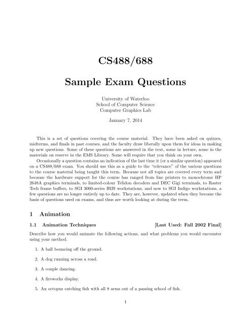
CS488/688<br />
Sample <strong>Exam</strong> <strong>Questions</strong><br />
University of Waterloo<br />
School of Computer Science<br />
Computer Graphi<strong>cs</strong> Lab<br />
January 7, 2014<br />
This is a set of questions covering the course material. They have been asked on quizzes,<br />
midterms, <strong>and</strong> finals in past courses, <strong>and</strong> the faculty draw liberally upon them for ideas in making<br />
up new questions. Some of these questions are answered in the text, some in lecture, some in the<br />
materials on reserve in the EMS Library. Some will require that you think on your own.<br />
Oc<strong>ca</strong>sionally a question contains an indi<strong>ca</strong>tion of the last time it (or a similar question) appeared<br />
on a CS488/688 exam. You should use this as a guide to the “relevance” of the various questions<br />
to the course material being taught this term. Be<strong>ca</strong>use not all topi<strong>cs</strong> are covered every term <strong>and</strong><br />
be<strong>ca</strong>use the hardware support for the course has ranged from line printers to monochrome HP<br />
2648A graphi<strong>cs</strong> terminals, to limited-colour Telidon decoders <strong>and</strong> DEC Gigi terminals, to Raster<br />
Tech frame buffers, to SGI 3000-series IRIS workstations, <strong>and</strong> now to SGI Indigo workstations, a<br />
few questions are no longer entirely up to date. They are, however, updated when they become the<br />
basis of questions used on exams, <strong>and</strong> thus are worth looking at during the term.<br />
1 Animation<br />
1.1 Animation Techniques [Last Used: Fall 2002 Final]<br />
Describe how you would animate the following actions, <strong>and</strong> what problems you would encounter<br />
using your method.<br />
1. A ball bouncing off the ground.<br />
2. A dog running across a road.<br />
3. A couple dancing.<br />
4. A fireworks display.<br />
5. An octopus <strong>ca</strong>tching fish with all 8 arms out of a passing school of fish.<br />
1
2 CS488/688 Introduction to Computer Graphi<strong>cs</strong><br />
1.2 Keyframing [Last Used: Winter 1998 Final]<br />
Suppose you had decided for your final project to extend your assignment 3 puppet into a key<br />
frame system.<br />
1. The current restrictions on the motion of the puppets shoulders <strong>and</strong> hips are too restrictive.<br />
Describe the additional degrees of freedom you would need to add to get reasonable motion,<br />
discuss what changes you would need to make to your data structure to support these degrees<br />
of freedom, <strong>and</strong> suggest a reasonable UI for manipulating the arms <strong>and</strong> legs given these new<br />
degrees of freedom.<br />
2. What additional functionality would you have to add to the program to support a key frame<br />
animation system?<br />
1.3 Animation <strong>and</strong> Splines [Last Used: Fall 2009 Final]<br />
Suppose we wish to animate a bouncing ball. We are given keyframes for the ball’s motion. The<br />
key frames are at times T={0,1,2,3,4,5,6} with associated height values of H={0,5,8,9,8,5,0}.<br />
a) Plot the graph of height versus time using linear interpolation between key frames.<br />
h<br />
10<br />
8<br />
6<br />
4<br />
2<br />
0<br />
0<br />
1 2 3 4 5 6<br />
b) Give an equation for the height h(t) over the interval t=4...5 using linear interpolation.<br />
c) In general, suppose we are given times T={t 0 , t 1 } <strong>and</strong> associated heights H={h 0 ,h 1 } what is<br />
the equation for h(t) in the interval [t 0 ,t 1 ] using linear interpolation?<br />
d) Suppose we wish to achieve a smoother animation by using Catmull-Rom interpolation. What<br />
would the parametric derivatives of the interpolated curve be at t=4 <strong>and</strong> t=5?<br />
e) Give 2D cubic Bezier control points for a Hermite interpolation given two sequential points<br />
(t 0 ,h 0 ) <strong>and</strong> (t 1 ,h 1 ) with associated derivatives v 0 <strong>and</strong> v 1 .<br />
– P 0 =<br />
7<br />
t
CS488/688 Introduction to Computer Graphi<strong>cs</strong> 3<br />
– P 1 =<br />
– P 2 =<br />
– P 3 =<br />
1.4 Euler Angles [Last Used: Winter 2000 Final]<br />
Euler angles are one method of representing orientations, with the orientation represented as a<br />
rotation around each coordinate axis. While common in computer graphi<strong>cs</strong>, Euler angles have<br />
several problems. To address these problems, people often use quaternions.<br />
For this question, we will use the following representation of Euler angles: With c a = cos(θ a )<br />
<strong>and</strong> s a = sin(θ a ), the matrix for Euler angles is<br />
R(θ x , θ y , θ z ) =<br />
⎡<br />
⎢<br />
⎣<br />
c y c z c y s z −s y 0<br />
s x s y c z − c x s z s x s y s z + c x c z s x c y 0<br />
c x s y c z + s x s z c x s y s z − s x c z c x c y 0<br />
0 0 0 1<br />
= R x (θ x )R y (θ y )R z (θ z ),<br />
where R x (θ x ), R y (θ y ) <strong>and</strong> R z (θ z ) are the st<strong>and</strong>ard rotation matrices.<br />
The following Euler angles <strong>and</strong> quaternion represent (to 3 digits of precision) the same orientation:<br />
θ x = 10, θ y = 90, θ z = 30<br />
q 1 = 0.696 − 0.123⃗i + 0.696⃗j + 0.123 ⃗ k<br />
1. (3 pts) Give a second set of distinct Euler angles β x , β y , β z that represent the same orientation.<br />
Your angles must be in the range [0, 360] degrees.<br />
β x =<br />
β y =<br />
β z =<br />
⎤<br />
⎥<br />
⎦<br />
2. (2 pts) Give the quaternion q 2 corresponding to your Euler angle solution in part (a) of this<br />
question.<br />
q 2 =<br />
1.5 Animation Techniques [Last Used: Winter 2006 Final]<br />
You are working on a scene in a movie that will incorporate ray traced CG characters of a Vice<br />
President shooting (with buckshot) an apologetic lawyer in slow motion. (Buckshot is a type of<br />
“bullet” that consists of many small pellets that spread out as they fly through the air.)<br />
Describe what part of the animation each of the following techniques could be used for, <strong>and</strong><br />
suggest <strong>and</strong> justify the use of a fifth technique that would be useful in creating this animation.<br />
1. Keyframing
4 CS488/688 Introduction to Computer Graphi<strong>cs</strong><br />
2. Particle systems<br />
3. Motion blur<br />
4. Inverse kinemati<strong>cs</strong><br />
Fifth technique:<br />
No point bonus question: In Texas, a hunting license costs $100. How much does a permit to<br />
shoot a lawyer cost?<br />
1.6 Animation—Quaternions [Last Used: Winter 2007 Final]<br />
1. A quaternion is a value of the form a + ib + jc + kd with real numbers a, b, c, <strong>and</strong> d, <strong>and</strong><br />
imaginaries i, j, <strong>and</strong> k. What property of the coefficients must hold in order for the quaternion<br />
to represent an orientation in 3D?<br />
2. Describe one of the problems with Euler angles that are solved by using quaternions to<br />
represent orientations.<br />
3. Explain or demonstrate with an example why the entries in a transformation matrix should<br />
not be interpolated directly.<br />
4. Now suppose we are animating a square with side length 1, centred at the origin. At time<br />
t = 0, the square is displayed with this 2D transformation matrix:<br />
⎡<br />
⎢<br />
⎣<br />
1 0 0<br />
0 1 0<br />
0 0 1<br />
Then, at time t = 1, the square is displayed with this matrix:<br />
⎡<br />
⎢<br />
⎣<br />
⎤<br />
⎥<br />
⎦<br />
√<br />
2 −<br />
√<br />
2 5<br />
√<br />
2<br />
√<br />
2 5<br />
0 0 1<br />
Derive a single matrix, whose entries are functions of time t, which animates between the<br />
states represented by these matrices. The square’s position, orientation <strong>and</strong> size should all<br />
change smoothly <strong>and</strong> minimally. The matrix should never distort the square into another<br />
shape. (Note: you <strong>ca</strong>n’t just animate the matrix entries using linear interpolation. But you<br />
<strong>ca</strong>n still write down a matrix parameterized by t that <strong>ca</strong>rries out the animation by considering<br />
how the square ought to move.)<br />
⎤<br />
⎥<br />
⎦<br />
2 Antialiasing<br />
2.1 Stochastic Sampling [Last Used: Winter 1995 Final]<br />
What are the advantage(s) of stochastic sampling over other antialiasing methods?
CS488/688 Introduction to Computer Graphi<strong>cs</strong> 5<br />
2.2 Super- <strong>and</strong> Sto<strong>ca</strong>stic-Sampling [Last Used: Winter 1996]<br />
Super-sampling <strong>and</strong> sto<strong>ca</strong>stic sampling are two methods for anti-aliasing.<br />
1. Describe both methods.<br />
2. With both techniques, we are still taking a discrete sampling of a continuous signal.<br />
Describe why/how each method reduces aliasing artifacts.<br />
2.3 Aliasing <strong>and</strong> Anti-aliasing [Last Used: Fall 2012 Final]<br />
• Describe 3 aliasing artifacts present in Computer Graphi<strong>cs</strong>.<br />
• Describe one method of anti-aliasing.<br />
2.4 Aliasing [Last Used: Winter 2000 Final]<br />
Suppose we wish to rasterize two triangles T1 <strong>and</strong> T2 given screen space coordinates for their<br />
vertices as indi<strong>ca</strong>ted in the diagram below.<br />
10<br />
5<br />
(3,5)<br />
T1<br />
(11,6)<br />
1<br />
1<br />
5<br />
T2<br />
10 15<br />
a) If both triangles are black on a white background, a naive approach would be to fill in each<br />
pixel that contains any piece of either triangle. What is the common name for the aliasing<br />
effect that would result?<br />
b) A triangle strip, often used to quickly render surfaces, is a sequence of triangles joined at<br />
shared edges. What is inefficient about rasterizing a triangle strip by filling the triangles<br />
one-at-a-time using the method in (a)?<br />
c) Suppose T1 has RGB colour (16,16,16), T2 has RGB colour (0,0,16) <strong>and</strong> the background has<br />
RGB colour (0,0,0). If the rasterization was antialiased using the obvious approach, what<br />
colour should pixel (3,5) be shaded? What colour should pixel (11,6) be shaded?<br />
d) Analytic antialiasing is difficult in ray tracing. Name an alternative approach <strong>and</strong> two possible<br />
variations.
6 CS488/688 Introduction to Computer Graphi<strong>cs</strong><br />
3 Backface Culling<br />
3.1 Perspective <strong>and</strong> Culling [Last Used: Spring 1992 Final]<br />
We may remove backfacing triangles from a polyhedral object with triangular faces by transforming<br />
each set of triangle vertices P 0 , P 1 , <strong>and</strong> P 2 into perspective space to obtain transformed points P ′ 0,<br />
P ′ 1, <strong>and</strong> P ′ 2, then computing a normal to the “prime” triangle, <strong>and</strong> finally checking the sign of the<br />
z component of this normal.<br />
(a) Explain why this computation correctly allows us to identify backfacing triangles.<br />
(b) Show, by the following example, that we <strong>ca</strong>nnot take the triangle normal in world space <strong>and</strong><br />
apply the perspective transformation to it to achieve any valid backfacing test in perspective<br />
space.<br />
EXAMPLE<br />
The eye is at position (0, 0, −d, 1) looking in the positive z direction at the origin. The<br />
x-y plane is the projection plane. The world-space triangle has vertices P 0 = (1, 0, 0, 1),<br />
P 1 = (0, 1, 0, 1), <strong>and</strong> P 2 = (0, 0, 1, 1). Develop a perspective matrix; transform the vertices<br />
by the matrix <strong>and</strong> divide by the resulting 4-th coordinate to produce the P ′ i points. Take a<br />
normal to the world-space triangle <strong>and</strong> subject it to a perspective transformation with the<br />
same matrix (no division — 4-th coordinate is zero, as it should be for a vector). Show that<br />
this resulting vector is not a normal for the “primed” triangle.<br />
Conventions<br />
All points in 2D have the form (x, y, 1) <strong>and</strong> in 3D the form (x, y, z, 1).<br />
All vectors in 2D have the form (x, y, 0) <strong>and</strong> in 3D the form (x, y, z, 0).<br />
All 4×4 transformation matrices (including perspective) in 3D act on vectors only with regard<br />
to to their upper-left-h<strong>and</strong> 3 × 3 submatrix.<br />
That is,<br />
4 Clipping<br />
⎡<br />
⎢<br />
⎣<br />
a e m r<br />
b f n s<br />
c g p t<br />
d h q u<br />
⎤ ⎡<br />
⎥ ⎢<br />
⎦ ⎣<br />
x<br />
y<br />
z<br />
0<br />
⎤<br />
⎡<br />
⎥<br />
⎦ is equivalent to ⎢<br />
⎣<br />
a e m 0<br />
b f n 0<br />
c g p 0<br />
0 0 0 0<br />
4.1 Frustum Clipping [Last Used: ?]<br />
Define the frustum of vision to be centered on the z-axis with the eyepoint at (0, 0, −d) <strong>and</strong> with<br />
the window on the x, y-plane having its center at (wcx, wcy, 0), width 2 ∗ wsx, <strong>and</strong> height 2 ∗ wsy.<br />
The far clipping plane is to be parallel to the window <strong>and</strong> intersect the z-axis at (0, 0, f).<br />
(a) Give the equations (in the window coordinate system) of the six clipping planes. Adjust the<br />
signs in your equations (if necessary) so that a positive value denotes ”visible” <strong>and</strong> a negative<br />
value denotes ”invisible”.<br />
(b) What is the perspective matrix appropriate for this formulation of the problem. Explain your<br />
answer!<br />
⎤ ⎡<br />
⎥ ⎢<br />
⎦ ⎣<br />
x<br />
y<br />
z<br />
0<br />
⎤<br />
⎥<br />
⎦
CS488/688 Introduction to Computer Graphi<strong>cs</strong> 7<br />
4.2 Anticlipping [Last Used: Winter 1986 <strong>Midterm</strong>]<br />
Discuss the changes necessary to draw only the portion(s) of a line segment that is(are) not contained<br />
within the clipping region. You may assume that points lying on the border of the clipping region<br />
are to be drawn. Show the outcode <strong>and</strong> window edge coordinate definitions for this <strong>ca</strong>se. Be sure<br />
to include the conditions for trivial acceptance <strong>and</strong> rejectance.<br />
4.3 Cross Product Rejection [Last Used: ?]<br />
The magnitude of the cross product between two vectors, v <strong>and</strong> w, is given by<br />
|v × w| = |v||w| sin(θ).<br />
The direction of the cross product perpendicular to the plane of v <strong>and</strong> w <strong>and</strong> points in the direction<br />
of the right h<strong>and</strong>’s thumb when the right h<strong>and</strong>’s fingers are curled in the v,w-plane from v to w.<br />
The magnitude of the cross product is just the area of the parallelepiped whose two adjacent sides<br />
are the vectors v <strong>and</strong> w.<br />
Show that, if a clipping window is defined in the x,y-plane, an acceptance/rejection test <strong>and</strong><br />
window-edge coordinates for points <strong>ca</strong>n be derived from the cross product.<br />
4.4 Polygon Splitting [Last Used: Fall 1990]<br />
You are given a sequence of three or more vertices p 0 , p 1 , p 2 , ... defining a convex polygon O in<br />
3-space, <strong>and</strong> the equation Ax + By + Cz + D = 0 of an arbitrarily oriented plane P . Describe an<br />
algorithm that splits O into two polygons O 1 <strong>and</strong> O 2 , with O 1 lying on or to one side of P , <strong>and</strong> O 2<br />
lying on or to the other side of P .<br />
Clearly written <strong>and</strong> commented pseudo-code or English is desired here, not hacker’s C. Be<br />
<strong>ca</strong>reful to explain <strong>and</strong> justify how each step of the computation is performed.<br />
4.5 Sutherl<strong>and</strong>-Hodgman Clipping [Last Used: Winter 1994 Final]<br />
The Sutherl<strong>and</strong>-Hodgman polygon clipping algorithm is described in the text in terms of a single<br />
clipping boundary. In practice we usually want to clip against some viewport. This involves passing<br />
the polygon through a series of clippers. For example:<br />
POLYGON->TopClipper->BottomClipper->LeftClipper->RightClipper->RESULT<br />
If we need to clip an edge at a boundary an expensive intersection <strong>ca</strong>lculation must be performed.<br />
(a) Show that the number of intersection <strong>ca</strong>lculations required is dependent on the order of the<br />
clippers. HINT: Consider the diagram below.<br />
(b) Prove, or give a counter-example to the statement : “In general there is a BEST ordering of<br />
the clippers.”
8 CS488/688 Introduction to Computer Graphi<strong>cs</strong><br />
V<br />
T<br />
V<br />
B<br />
V L<br />
V<br />
R<br />
4.6 Pipeline [Last Used: Fall 1996 <strong>Midterm</strong>]<br />
Excluding clipping, the stages of the three dimensional graphi<strong>cs</strong> pipeline are given by the following<br />
diagram:<br />
A<br />
B<br />
¡<br />
C<br />
D<br />
E<br />
¢<br />
F<br />
Modeling<br />
Transformations<br />
Viewing<br />
Transformation<br />
Perspective<br />
Transformation<br />
Window−to<br />
Viewport<br />
Rasterization<br />
At which point (A-F) do we normally perform clipping <strong>and</strong> why do we clip there rather than<br />
at one of the other steps? (Each point is considered to be between two steps of the pipeline except<br />
A <strong>and</strong> F, which are before <strong>and</strong> after the entire pipeline, respectively. Point B, for example, occurs<br />
after modeling transformations <strong>and</strong> before viewing transformations.)<br />
4.7 Clipped Convex Polygon Vertices [Last Used: Winter 1993 <strong>Midterm</strong>]<br />
Suppose you clip a convex polygon with n vertices to a square window. What is the maximum<br />
number of vertices that the clipped polygon <strong>ca</strong>n have?<br />
4.8 Clippped Con<strong>ca</strong>ve Polygon Vertices [Last Used: ?]<br />
Suppose you clip a con<strong>ca</strong>ve polygon with n vertices to a square window. What is the maximum<br />
number of vertices the clipped polygon might have?<br />
4.9 Degenerate Polygons [Last Used: ?]<br />
In class, we showed that clipping a con<strong>ca</strong>ve polygon to a rectangular window may result in degeneracies.<br />
State a simple test of the clipped polygon to determine if it has degeneracies.<br />
4.10 Diamond-shaped Window [Last Used: Fall 2004 <strong>Midterm</strong>]<br />
In our window-to-viewport mapping, we assumed that both the window <strong>and</strong> viewport were rectangular<br />
in shape <strong>and</strong> aligned with the coordinate axes. In the following, assume that the viewport<br />
is rectangular <strong>and</strong> aligned with the coordinate axes. Suppose that the window is rectangular, but<br />
not aligned with the coordinate axes. To simplify the problem, assume the edges of the window<br />
form a 45 degree angle with the coordinate axes, with one corner at (x0, y0), a second corner at
CS488/688 Introduction to Computer Graphi<strong>cs</strong> 9<br />
(x1, y1), <strong>and</strong> with the window having a width of w <strong>and</strong> height of h as shown in the figure below.<br />
Further, assume we want to map this window to a viewport that is fully defined by the two points<br />
(vx0, vy0) <strong>and</strong> (vx1, vy1). The mapping should map (x0, y0) to (vx0, vy0) <strong>and</strong> map (x1, y1) to<br />
(vx1, vy0). Explain how we would perform the window-to-viewport mapping.<br />
(x1,y1)<br />
(vx1,vy1)<br />
h<br />
w<br />
(x0,y0)<br />
(vx0,vy0)<br />
(vx1,vy0)<br />
4.11 Clip to Window with Hole [Last Used: Spring 2000 <strong>Midterm</strong>]<br />
Suppose we wish to clip lines to a rectangular window with a rectangular hole in it:<br />
The shaded region is our "window" A set of lines before clipping A set of lines after clipping<br />
Call the outer rectangle R with vertices r 0 , r 1 , r 2 , <strong>and</strong> r 3 , <strong>and</strong> <strong>ca</strong>ll the inner rectangle H with<br />
vertices h 0 , h 1 , h 2 , <strong>and</strong> h 3 . You may assume that h i is the corner closest to r i . Describe an<br />
algorithm for clipping lines to this object.<br />
4.12 Clipping (Variation of Previous) [Last Used: Spring 1997 <strong>Midterm</strong>]<br />
Suppose we have a rectangular window with a triangular hole in it:<br />
The shaded region is our "window" A set of lines before clipping A set of lines after clipping<br />
• Present the formulas of all the intersection computations needed to clip lines to this window.<br />
• Is an outcode scheme possible for this “window”? If not, explain why. If so, propose one.
10 CS488/688 Introduction to Computer Graphi<strong>cs</strong><br />
4.13 Specific Clipping Problem [Last Used: Winter 2006 <strong>Midterm</strong>]<br />
Suppose we clip polygon P = (v 0 , . . . , v 5 ) to window W in the following situation using the repeated<br />
half-plane clipping algorithm:<br />
v<br />
5<br />
v<br />
1<br />
P<br />
W<br />
v<br />
0<br />
v<br />
2<br />
v<br />
4<br />
v<br />
3<br />
Label any new vertices resulting from clipping in the figure above as p 0 , . . . , p i . Give an ordered<br />
list of the vertices of the clipped polygon. You may chose any vertex as the initial vertex.<br />
4.14 Specific Clipping Problem [Last Used: Winter 1998 <strong>Midterm</strong>]<br />
Suppose we clip polygon P = (v 0 , . . . , v 7 ) to window W in the following situation using the repeated<br />
half-plane clipping algorithm:<br />
V<br />
V<br />
7 6<br />
V<br />
3<br />
V<br />
2<br />
W<br />
P<br />
V<br />
5<br />
V<br />
4<br />
V 0<br />
V 1<br />
Label any new vertices resulting from clipping in the figure above as p 0 , . . . , p i . Give an ordered<br />
list of the vertices of the clipped polygon. You may chose any vertex as the initial vertex.<br />
4.15 Clipping [Last Used: Winter 1996 Final]<br />
1. When designing fast algorithms, although it is important to h<strong>and</strong>le the common <strong>ca</strong>ses quickly,<br />
it is acceptable to spend more time on the less common <strong>ca</strong>ses.<br />
In lecture, to clip a single line segment to a window, we performed repeated half-space clipping.<br />
Describe how we clip a line segment to a single half-space, noting how the “common <strong>ca</strong>ses”<br />
are h<strong>and</strong>led quickly relative to the “less common <strong>ca</strong>ses”.<br />
Note: The question is not asking about outcodes.
CS488/688 Introduction to Computer Graphi<strong>cs</strong> 11<br />
2. If we clip a polygon to a window, it is inadequate to merely perform repeated half-space<br />
clipping on each polygon line segment independently. Give an example illustrating why<br />
independent clipping of polygon line segments may fail to correctly clip a convex polygon. A<br />
picture alone is inadequate; you should also give a short answer describing the picture <strong>and</strong><br />
why it illustrates the problem, noting both the incorrectly clipped polygon <strong>and</strong> what the<br />
correctly clipped polygon should be.<br />
4.16 Line Clipping [Last Used: Fall 2012 Final]<br />
In assignment 2, you implemented a line clipping algorithm by repeatedly clipping to half-spaces.<br />
Suppose we want to clip a polygon to a rectangular window. One approach would be to just clip<br />
each line segment to the window independently, <strong>and</strong> use the resulting clipped line segments as our<br />
clipped polygon.<br />
Given an example illustrating that this algorithm may give an incorrect result.<br />
5 Colour<br />
5.1 Colour Coordinate Systems [Last Used: Spring 1986 Final]<br />
Name three colour coordinate systems <strong>and</strong> describe their defining axes. For each system, indi<strong>ca</strong>te<br />
the shape of the region containing the colours they <strong>ca</strong>n define.<br />
5.2 Additive <strong>and</strong> Subtractive Colour [Last Used: ?]<br />
Explain the difference between additive <strong>and</strong> subtractive colour mixing.<br />
(a) According to the opponent-colour theory of vision, what information is passed on to the brain<br />
from the eye <strong>and</strong> how is it generated from cone excitations?<br />
(b) Explain the relevance of opponent-colour theory to computer graphi<strong>cs</strong>.<br />
5.3 Colour Space Mapping [Last Used: Winter 1986 Final]<br />
The colours D, E, F are defined in terms of the R, G, B primaries as:<br />
D = 1.0R + 0.5G (1)<br />
E = 1.0R − 0.5B (2)<br />
F = 1.0R (3)<br />
(a) What are D, E, F values that produce an equivalent stimulus to the eye as R = 0.0, G = 1.0,<br />
<strong>and</strong> B = 1.0?<br />
(b) Write the equations that map from three values in DEF colour space into RGB colour space.<br />
(c) Can the colours D, E, F be considered as primaries? Justify your answer.
12 CS488/688 Introduction to Computer Graphi<strong>cs</strong><br />
5.4 Exact Colour [Last Used: Fall 1990]<br />
Suppose that we are designing a modelling program for a museum that will use images generated<br />
by our software to evaluate architectural <strong>and</strong> lighting proposals for the interior of a new building,<br />
<strong>and</strong> that it is particularly important to model accurately the appearance of the paintings that will<br />
hang in the building. Explain why representing object colour by RGB triplets would probably not<br />
be satisfactory.<br />
6 Geometry<br />
6.1 Affine combination [Last Used: Fall 2011 Final]<br />
Which of the following are valid expressions in affine geometry, where P, Q, R are points, ⃗v is a<br />
vector, <strong>and</strong> B n i (t) = ( n<br />
i) (1 − t) n−i t i .<br />
Expression Valid? Expression Valid? Expression Valid?<br />
(P + Q)/2 2P − Q Q − 2P<br />
P − 2Q + R P − 20⃗v P − 2Q + ⃗v<br />
(1 − t)P + tQ cos 2 (t)P + sin 2 ∑<br />
(t)R<br />
ni=1<br />
Bi n(t)P i<br />
(P + Q)/R R/(P · Q) ⃗v × (P − Q)<br />
6.2 Spaces [Last Used: Winter 2007 <strong>Midterm</strong>]<br />
Here, in alphabetic order, are the four kinds of spaces we constructed to underst<strong>and</strong> the geometry<br />
of computer graphi<strong>cs</strong>:<br />
1. Affine space<br />
2. Cartesian space<br />
3. Euclidean space<br />
4. Vector space<br />
Write them in order so that each space is an extension of the previous one. Between every two<br />
spaces, write down what was added to the first space to get the second one.<br />
Which of these spaces is the simplest one in which we <strong>ca</strong>n talk about parallel lines?<br />
Which of these spaces is the simplest one in which we <strong>ca</strong>n talk about perpendicular lines?<br />
6.3 Planar Polygon Test [Last Used: ?]<br />
Given a sequence of n points P 1 , . . . , P n in in three dimensions, describe a boolean function<br />
Planar(P 1 , . . . , P n ) that returns true if <strong>and</strong> only if the points lie in a common plane. If you give<br />
pseudo-code, comment the code to indi<strong>ca</strong>te what it is doing.
CS488/688 Introduction to Computer Graphi<strong>cs</strong> 13<br />
6.4 Geometric Meaning [Last Used: Fall 2010 Final]<br />
Suppose P, Q, R are non-colinear points in a Euclidean three space E, <strong>and</strong> ⃗v <strong>and</strong> ⃗w are vectors<br />
defined as ⃗v = P − Q <strong>and</strong> ⃗w = Q − R. Let A be an affine transformation whose domain is E <strong>and</strong><br />
whose range is an arbitrary Euclidean space. Let < ⃗u, ⃗w > denote the dot product of ⃗u <strong>and</strong> ⃗w,<br />
let the cross product of these two vectors be denoted as ⃗u × ⃗w, <strong>and</strong> let |⃗v| denote the length of the<br />
vector ⃗v.<br />
Each expression in the following table may or may not have geometric meaning, <strong>and</strong> if an<br />
expression does have geometric meaning, the expression may or may not be an equality. You<br />
should check the box the best describes the equality.<br />
• Check the ‘ng’ box if the expression potentially has no geometric meaning;<br />
• Check the ‘=’ box if the expression will always have geometric meaning, <strong>and</strong> if the expressions<br />
on either side of the ‘?=’ will always be equal;<br />
• Check the ‘≠’ box if the expression will always have geometric meaning, but the expressions<br />
on either side of the ‘?=’ might not be equal.<br />
Expression = ≠ ng<br />
P ?= Q + ⃗v<br />
A(P ) ?= A(Q) + A(⃗v)<br />
A(P + Q) ?= A(P ) + A(Q)<br />
A(⃗v + ⃗w) ?= A(⃗v) + A( ⃗w)<br />
A((1 − t)P + tQ) ?= (1 − t)A(P ) + tA(Q)<br />
< ⃗v, ⃗v × ⃗w > ?= 0<br />
< A(⃗v), A(⃗v × ⃗w) > ?= 0<br />
|⃗v| ?= |A(⃗v)|<br />
R + A(⃗v + ⃗w) ?= R + A(⃗v) + A( ⃗w)<br />
A(P ) + A(⃗v) + A( ⃗w) ?= A(R)<br />
6.5 Geometric Ambiguity [Last Used: Spring 1997 <strong>Midterm</strong>]<br />
We are given a pair of 2 dimensional points, a 2 dimensional vector, <strong>and</strong> a matrix:<br />
P =<br />
⎡<br />
⎢<br />
⎣<br />
a<br />
b<br />
1<br />
⎤<br />
⎥<br />
⎦ ,<br />
⎡ ⎤<br />
c<br />
Q = ⎢<br />
⎣ d ⎥<br />
⎦ ,<br />
1<br />
⎡ ⎤<br />
r<br />
⃗v = ⎢<br />
⎣ s<br />
0<br />
⎥<br />
⎦ ,<br />
M = ⎡<br />
⎢<br />
⎣<br />
2 0 −2<br />
0 1 0<br />
0 0 1<br />
1. Give at least three geometric interpretations of MP . Sketch a picture for each interpretation.<br />
2. For each of your interpretations, in order, what will be the length of M⃗v?<br />
3. For which of your three interpretations of MP will it be meaningless to talk about the distance<br />
between Q <strong>and</strong> MP ? For which interpretation will the distance between Q <strong>and</strong> MP be the<br />
same as the distance between Q <strong>and</strong> P ? For which interpretation will the following expression<br />
⎤<br />
⎥<br />
⎦
14 CS488/688 Introduction to Computer Graphi<strong>cs</strong><br />
be meaningful?<br />
Q − MP ≡<br />
⎡<br />
⎢<br />
⎣<br />
c<br />
d<br />
1<br />
⎤ ⎡<br />
⎥<br />
⎦ − ⎢<br />
⎣<br />
2 0 −2<br />
0 1 0<br />
0 0 1<br />
⎤ ⎡<br />
⎥<br />
⎦ ⎢<br />
⎣<br />
a<br />
b<br />
1<br />
⎤<br />
⎥<br />
⎦<br />
4. What information must we know to fully interpret the matrix product MP unambiguously?<br />
6.6 Geometric [Last Used: Winter 2007 Final]<br />
The following questions are in the context of an OpenGL rendering appli<strong>ca</strong>tion in which back-face<br />
culling <strong>and</strong> depth testing is always enabled. A user has modelled various objects but when they<br />
try to use them with this system they run into a number of problems. Try to diagnose each of the<br />
problems they encounter.<br />
1. The user has modelled a symmetric object by only modelling the left side <strong>and</strong> then using a<br />
reflection to model the right side. The left side renders correctly but the right side does not.<br />
What might be going on?<br />
2. The user has modelled an object, but when they render it they see strange jagged stripy<br />
patterns on the surface, <strong>and</strong> these patterns change with the viewpoint. The problem is much<br />
worse when the model is far away. There is no texture on this model, <strong>and</strong> aliasing problems<br />
have been ruled out. What might be going on?<br />
3. The user has modelled an object, but when they render it, parts that should be visible through<br />
holes in the surface seem to be missing. What might be going on?<br />
4. The user has modelled an object, but when they render it, the edges between certain polygons<br />
oc<strong>ca</strong>sionally have missing pixels <strong>and</strong> holes in the surface through which the color of the<br />
background is visible. The user insists that all vertices lie on the boundaries of other polygons<br />
in the mesh <strong>and</strong> shared parts of edges are aligned so the mesh should be watertight. What<br />
might be going on?<br />
7 GPU<br />
7.1 Shaders, toon shading [Last Used: Fall 2010 Final]<br />
You are to write the fragment shader for an OpenGL toon shader. The vertex shader computes an<br />
“albedo” value (i.e., the cosine term computed in Lambertian/diffuse shading) with the following<br />
code:<br />
varying float albedo ;<br />
void main ( )<br />
{<br />
vec3 pos_EC = vec3 ( gl_ModelViewMatrix * gl_Vertex );<br />
vec3 normal_EC = normalize ( gl_NormalMatrix * gl_Normal ) ;<br />
vec3 light_EC = normalize ( gl_LightSource[0].position.xyz - pos_EC );
CS488/688 Introduction to Computer Graphi<strong>cs</strong> 15<br />
}<br />
albedo = dot ( normal_EC , light_EC ) ;<br />
gl_Position = ftransform( ) ;<br />
Write the code for the fragment shader that uses a bright red material if the albedo term is<br />
greater than 0.7 <strong>and</strong> a dark red material otherwise.<br />
Fragment shader note: the resulting colour should be stored in the variable gl FragColor.<br />
7.2 Shadow Maps [Last Used: Winter 2013 Final]<br />
Shadow maps are one method of generated shadows using OpenGL. Describe how to implement<br />
shadow maps.<br />
8 Hidden Surfaces<br />
8.1 Visible Surface Algorithms [Last Used: Winter 1998 <strong>Midterm</strong>]<br />
This question concerns the following algorithms which address the visible surface problem:<br />
1. The binary space partitioning algorithm (BSP)<br />
2. Warnock’s algorithm<br />
3. The Painter’s algorithm<br />
4. Backfacing polygon removal<br />
5. Z-buffering<br />
(a) Briefly describe the visible surface problem.<br />
(b) Give the number (or numbers) of the relevant algorithms for the following questions (if none<br />
of the algorithms have the sated property, write ’none’):<br />
Which algorithms<br />
A. involve area subdivision?<br />
B. require building a tree?<br />
C. often use extra memory hardware?<br />
D. require signifi<strong>ca</strong>nt preprocessing time?<br />
E. require knowing polygon orientations?<br />
F. involve comparing pixel depths?<br />
G. are device independent?<br />
H. are view-independent?<br />
I. <strong>ca</strong>n be easily implemented in hardware?<br />
J. which algorithm is clearly insufficient to solve the visible surface problem?
16 CS488/688 Introduction to Computer Graphi<strong>cs</strong><br />
(c) Briefly describe each of the four algorithms.<br />
(d) OpenGL provides support for backfacing polygon removal. Give a brief algorithm for determining<br />
whether a simple convex polygon’s vertices in screen space are oriented clockwise or<br />
counterclockwise.<br />
8.2 Backface culling, Painter’s algorithm [Last used: Winter 2013 Final]<br />
The picture below is an example of the 2D version of the hidden surface removal problem. In this<br />
problem, we want to render those portions of the lines that are visible to the viewer.<br />
B<br />
A<br />
C<br />
E<br />
v<br />
F<br />
H<br />
I<br />
J<br />
K<br />
D<br />
G<br />
L<br />
Note: For the purposes of this problem, we are thinking of the eyepoint E as being lo<strong>ca</strong>ted at<br />
the front of the eye (ie, where the line representing ⃗v starts).<br />
• Suppose we use backface culling to remove some lines segments before drawing them. Which<br />
lines will be drawn after culling? What visual artifacts (due to deficiencies of this hidden line<br />
removal algorithm) will we (potential) see?<br />
• Give a simple test (eg, no more than 3 lines of code) to determine whether we should backface<br />
cull (remove) a line segment X. Assume that the line segment X has normal X.n <strong>and</strong> is<br />
defined by its endpoint, X.v1 <strong>and</strong> X.v2.<br />
• Suppose instead of backface culling that we use the Painter’s algorithm. In which order will<br />
the line segments be drawn? (Note: This order is not unique; you just have to give any one<br />
order that the Painter’s algorithm might produce). What visual artifacts (due to deficiencies<br />
of this hidden line removal algorithm) will we (potential) see?<br />
8.3 Warnock’s Algorithm [Last Used: Fall 1997 Final]<br />
In the picture below, the large square is the region of interest on the screen, the dotted lines show<br />
the boundaries between pixels, <strong>and</strong> the two triangles <strong>and</strong> the two quadrilateral are polygons that<br />
we want to draw on the screen.<br />
In this figure, indi<strong>ca</strong>te the regions into which Warnock’s hidden surface removal algorithm will<br />
subdivide the screen.
CS488/688 Introduction to Computer Graphi<strong>cs</strong> 17<br />
16<br />
15<br />
14<br />
13<br />
12<br />
11<br />
10<br />
9<br />
8<br />
7<br />
6<br />
5<br />
4<br />
3<br />
2<br />
1<br />
0<br />
0<br />
1 2 3 4 5 6 7<br />
8<br />
9 10 11 12 13 14 15 16<br />
8.4 Painter’s Algorithm [Last Used: Fall 2002 <strong>Midterm</strong>]<br />
Suppose you implement the Painter’s Algorithm for hidden surface removal. Assume you have<br />
implemented the algorithm for non-overlapping polygons <strong>and</strong> non-overlapping polygons only (i.e.,<br />
for when for each pair of polygons at least one of the x, y, or z extents do not overlap).<br />
1. Describe in words what you would have to change/implement in your code to render the<br />
following scene:<br />
2. Indi<strong>ca</strong>te in the picture what you code from part (a) would do to these polygons, label the<br />
polygons, <strong>and</strong> give an order in which the Painter’s Algorithm would render them (the order<br />
may not not unique; any correct order is acceptable).<br />
8.5 Z Buffer/Convex Polygons [Last Used: Fall 1990]<br />
(a) Sketch the organization of a z-buffer hidden surface algorithm for convex polygons.<br />
(b) Describe the storage requirements under a reasonable set of assumptions. (State your assumptions!)<br />
What is the complexity of this algorithm?<br />
(c) Explain how to reorganize the algorithm so as to completely compute the image on one s<strong>ca</strong>n<br />
line before proceeding to the next.
18 CS488/688 Introduction to Computer Graphi<strong>cs</strong><br />
(d) Explain how to modify the algorithm so as to completely compute the image at one pixel<br />
before proceeding to the next. In what circumstances would this be a desirable thing to do?<br />
(e) Indi<strong>ca</strong>te how to modify the algorithm of (c) so as to h<strong>and</strong>le con<strong>ca</strong>ve polygons.<br />
8.6 Z Buffer vs. Watkins, Ray Tracing [Last Used: Fall 1986 Final]<br />
(a) Define the term depth buffer (z buffer) <strong>and</strong> explain how a depth buffer <strong>ca</strong>n be used to solve<br />
the hidden surface problem without explicitly computing polygon intersections.<br />
(b) Does the depth buffer algorithm take advantage of s<strong>ca</strong>n line coherence? Explain your answer.<br />
(c) Compare the depth buffer algorithm with Watkin’s algorithm for hidden surface elimination.<br />
Under what circumstances would one algorithm be preferable over the other? Relative criteria<br />
for judgement include time <strong>and</strong> space requirements, ability to incorporate transparency <strong>and</strong><br />
anti-aliasing, <strong>and</strong> ease of programming. Justify your answer.<br />
(d) Keeping in mind what you wrote for part (c), what are the advantages/disadvantages of naive<br />
ray tracing as introduced by Turner Whitted in 1979?<br />
(e) Distributed ray tracing was first introduced in 1984 by Cook, Porter & Carpenter from Lu<strong>ca</strong>sfilm.<br />
How does it differ from the naive ray tracing algorithm? Explain.<br />
(f) Keeping in mind what you wrote for parts (c), (d) <strong>and</strong> (e), what are the advantages/disadvantages<br />
of distributed ray tracing?<br />
8.7 Z Buffer <strong>and</strong> Translucency [Last Used: Spring 2000 Final]<br />
The st<strong>and</strong>ard z-buffer algorithm in the raster subsystem of most workstations goes like this:<br />
for each draw-object request {<br />
for each pixel covered by the object {<br />
if (the object z is greater than the stored z) {<br />
replace the color by the object color;<br />
replace the stored z by the object z;<br />
}<br />
}<br />
}<br />
This assumes that objects are opaque. If objects are translucent, then the color of a pixel should<br />
be, recursively,<br />
factor * front-object-color<br />
+<br />
(1 - factor) * color-resulting-from-all-further-objects<br />
where factor is a number between 0 <strong>and</strong> 1 related to the light transmission properties of the front<br />
object. Why <strong>ca</strong>n’t we h<strong>and</strong>le this with the the z-buffer algorithm? Are there any modifi<strong>ca</strong>tions of<br />
the z-buffer algorithm that you <strong>ca</strong>n think of for h<strong>and</strong>ling transparency? If so, describe them briefly.<br />
If not, <strong>ca</strong>n you say what the insurmountable difficulty with the algorithm is?<br />
An interesting picture to look at while you are thinking is the following:
CS488/688 Introduction to Computer Graphi<strong>cs</strong> 19<br />
9 Hierarchy<br />
9.1 Hierarchi<strong>ca</strong>l Modeling: A3 <strong>and</strong> A4 [Last Used; Winter 2013 Final]<br />
You implemented hierarchi<strong>ca</strong>l modeling in both assignment 3 <strong>and</strong> assignment 4. If done correctly,<br />
you could have used the puppet you modeled in assignment 3 as a model for your ray tracer in<br />
assignment 4. However, despite the hierarchies being the same, the code you wrote in the two<br />
assignments did very different things when traversing the hierarchies.<br />
Discuss these difference by outline the operations performed on the hierarchies by each assignment.<br />
9.2 2D Hierarchi<strong>ca</strong>l Modeling [Last Used: Winter 2004 <strong>Midterm</strong>]<br />
In this question, the following notation is used: I is the do-nothing identity transformation, T (x, y)<br />
is a 2D translation by vector (x, y), S(x, y) is a non-uniform s<strong>ca</strong>le with factors x <strong>and</strong> y, <strong>and</strong> R(θ)<br />
is a counter-clockwise rotation about the origin by angle θ (in degrees).<br />
We want to model the following 2D “checker board”:<br />
Draw a DAG to model the checker board, with a single root node <strong>and</strong> a single leaf node<br />
containing a unit square centered at the origin as shown below. You should draw your internal<br />
nodes as boxes with one of the transformations listed above. The boxes should be connected with<br />
ar<strong>cs</strong>; you may use multiple ar<strong>cs</strong> to/from any box. You may use no more than 6 transformations<br />
(i.e., you may have no more than 6 internal nodes).
20 CS488/688 Introduction to Computer Graphi<strong>cs</strong><br />
root<br />
9.3 Hierarchi<strong>ca</strong>l Swinging Links [Last Used: Fall 1995 Final]<br />
The schematic diagram that follows shows a 4-link jointed structure hanging from the ceiling. Each<br />
link has length L, <strong>and</strong> for simplicity we model each link object using an affine transformation of<br />
the line segment (0, 0, 0)(0, 0, −L). The black circles indi<strong>ca</strong>te pivot (rotation) points (assumed to<br />
have no diameter). The rotations are indi<strong>ca</strong>ted by arrows. We want to simulate this structure as<br />
it swings under gravity, but first we have to build it.<br />
Part (a) : Set up a display structure of the sort discussed in lectures (transformation nodes, object<br />
nodes, sibling links, child links) that represents this jointed structure.<br />
Part (b) : Show how the matrix stack will change as you traverse your data structure.
CS488/688 Introduction to Computer Graphi<strong>cs</strong> 21<br />
9.4 Hierarchi<strong>ca</strong>l Robot Arm [Last Used: Fall 1992 Final]<br />
We wish to model the robot arm depicted below. You are to design an appropriate display structure.<br />
Show the nodes, their hierarchy, <strong>and</strong> what purpose each node serves (e.g. rotation about z-axis or<br />
base object).<br />
The base (A) <strong>ca</strong>n rotate about the z axis. The post (B) <strong>ca</strong>n extend <strong>and</strong> retract along the z<br />
axis. It moves in <strong>and</strong> out of the base like a piston in a cylinder. The joint (C) <strong>ca</strong>n rotate about<br />
an axis parallel to the x − y plane (orientation depending on how the base has rotated). The angle<br />
that the upper arm (D) makes with the post is determined by the rotation of this joint. The lower<br />
arm (E) slides in <strong>and</strong> out along the upper arm, like a piston in a cylinder. The grippers (F) pivot<br />
at their ends of attachment to the upper arm.<br />
All components (A through E <strong>and</strong> both F’s) are formed by s<strong>ca</strong>ling a cylinder with unit diameter<br />
<strong>and</strong> unit height whose base is centered at the origin:<br />
z<br />
y<br />
x<br />
A has height h A <strong>and</strong> diameter d A , <strong>and</strong> similarly for all other components. In building your<br />
data structure, do not worry about restrictions on rotations or translations, since that would add<br />
too many compli<strong>ca</strong>tions for the time you have.<br />
z<br />
y<br />
C<br />
B<br />
D<br />
E<br />
F<br />
x<br />
A<br />
9.5 Cube Array [Last Used: Spring 1992 Final]<br />
Below is a data structure that, if properly walked <strong>and</strong> interpreted, will result in the display of 3<br />
rows each consisting of 3 copies of the cube represented by the node “C”. The nodes with a “T” label<br />
are translations. “T0” is the translation that takes (x, y, z) to (x, y − 4, z). “T1” is the translation<br />
that takes (x, y, z) to (x, y, z). “T2” is the translation that takes (x, y, z) to (x, y + 4, z). “T3” is the<br />
translation that takes (x, y, z) to (x − 4, y, z). “T4” is the translation that takes (x, y, z) to (x, y, z).<br />
“T5” is the translation that takes (x, y, z) to (x + 4, y, z). The “R” node is a rotation, <strong>and</strong> the “S”<br />
node is a s<strong>ca</strong>le.
22 CS488/688 Introduction to Computer Graphi<strong>cs</strong><br />
T0 ✲ T1 ✲ T2<br />
✟<br />
✟<br />
✟<br />
✟<br />
✟✙ ✘ ✘✘ ✘ ✘✘ ✘ ✘✘ ✘<br />
❄✘✘✾<br />
T3 ✲ T4 ✲ T5<br />
✟<br />
✟<br />
✟<br />
✟✙ ✘<br />
✟ ✘ ✘ ✘✘ ✘ ✘✘ ✘ ✘<br />
❄✘✘✾<br />
R<br />
❄<br />
S<br />
❄<br />
C<br />
(a) Show how the successive stages of the matrix stack will look as this data structure is walked<br />
in a depth-first manner (the manner presented in class).<br />
(b) Change the data structure so as to omit the s<strong>ca</strong>ling on the topmost row of cubes (the one<br />
corresponding to the (x, y + 4, z) translation).<br />
(c) How would you use the IRIS picking mode <strong>and</strong> namestack to permit any of the 9 cubes on the<br />
screen to be picked individually?<br />
(d) How would you modify the data structure to permit any cube, once picked, to be s<strong>ca</strong>led<br />
uniformly larger or smaller?<br />
9.6 Hierarchi<strong>ca</strong>l Ray Tracing [Last Used: Spring 2000 Final]<br />
When ray tracing a hierarchi<strong>ca</strong>l model, you <strong>ca</strong>n transform the ray instead of transforming the<br />
primitives. This allows you to specialize your ’ray-intersect-object’ code as you only need to intersect<br />
the ray with simple primitives.<br />
Assume we have a simple scene consisting of one object (a geometric primitive, P ) that has been<br />
transformed by a series of two transformations, T 1 <strong>and</strong> T 2 as illustrated in the following hierarchy<br />
tree:<br />
T 1<br />
T 2<br />
P
CS488/688 Introduction to Computer Graphi<strong>cs</strong> 23<br />
Describe the ray tracing process discussed in the paragraph above on a ray (p, ⃗v) as it is traced<br />
in this scene. Assume that the transformed ray strikes the simple primitive at point q <strong>and</strong> that the<br />
primitive has normal ˆn at q, where both q <strong>and</strong> ˆn are specified relative to the modeling coordinates<br />
of the simple primitive.<br />
Be sure to note what geometric entities get transformed <strong>and</strong> what transformation they get<br />
transformed by, what ray is used in the object intersection <strong>ca</strong>lculation, <strong>and</strong> what geometric surface<br />
information is used in the actual shading <strong>ca</strong>lculation.<br />
9.7 Ray Tracing <strong>and</strong> Hierarchi<strong>ca</strong>l Transformations [Last Used: Winter 2000<br />
<strong>Midterm</strong>]<br />
Suppose you are given the following parameters for viewing a scene relative to a left h<strong>and</strong>ed world<br />
frame:<br />
View direction: (0, -3, 4)<br />
Up vector: (0, 1, 0)<br />
Eye point: (0, 10, -10)<br />
Field of view: 90 degrees<br />
a) Define a left h<strong>and</strong>ed orthonormal view frame with respect to the world frame. The z-axis should<br />
point in the view direction, the y-axis should be in the same plane as the view direction <strong>and</strong><br />
the up vector, <strong>and</strong> the origin should be at the eye point.<br />
b) Give a change of basis matrix from coordinates relative to the view frame to coordinates relative<br />
to the world frame.<br />
c) Suppose you are given the following DAG. Transformation matrices V, M, <strong>and</strong> L represent<br />
change of basis transformations from child space to parent space. We have found a ray-object<br />
intersection point <strong>and</strong> normal in model space <strong>and</strong> wish to perform a lighting <strong>ca</strong>lculation in<br />
light space. Indi<strong>ca</strong>te the required transformation to convert E V , P M <strong>and</strong> N M into light space<br />
(fill in the blanks below).<br />
World Space<br />
V M L<br />
View Space Model Space Light Space<br />
EV<br />
P M<br />
E<br />
=<br />
L<br />
EV<br />
N M<br />
P<br />
=<br />
L<br />
P M<br />
N =<br />
L<br />
N M<br />
?<br />
?<br />
?<br />
9.8 Hierarchi<strong>ca</strong>l Transformations [Last Used: Winter 2006 Final]<br />
Suppose you are given the following two-dimensional CSG scene hierarchy
24 CS488/688 Introduction to Computer Graphi<strong>cs</strong><br />
Union<br />
Intersect<br />
A<br />
A−B<br />
B<br />
A−B<br />
B<br />
A<br />
T(5,4)<br />
T(1,2)<br />
S(3,6)<br />
T(4,5)<br />
S(2,2)<br />
T(5,2)<br />
S(2,6)<br />
T(4,2)<br />
S(4,6)<br />
Union<br />
T(2,2)<br />
where the circles <strong>and</strong> squares at the bottom are primitives, the T(x,y) nodes represent translations<br />
by those amounts, the S(sx,sy) nodes represent non-uniform s<strong>ca</strong>les by those amounts, <strong>and</strong> the A-B,<br />
Union, <strong>and</strong> Intersect nodes represent those CSG operations.<br />
In the grid below, draw the resulting scene. In this figure, we have drawn the square <strong>and</strong> circle<br />
primitives in their base lo<strong>ca</strong>tions. We have drawn them “hollow” to indi<strong>ca</strong>te their lo<strong>ca</strong>tions more<br />
clearly; however, you should think of them as “filled in” as shown in CSG tree above, <strong>and</strong> you<br />
should shade in the appropriate areas in your figure below.<br />
10 Input<br />
10.1 Virtual Input Devices [Last Used: Winter 1992 <strong>Midterm</strong>]<br />
(a) The text names six virtual graphic input primitives:<br />
lo<strong>ca</strong>tor, pick, choice, valuator, string, stroke<br />
Write a brief (one or two sentence) description of each.<br />
(b) With the exception of pick, indi<strong>ca</strong>te a “natural” hardware device to associate with each.<br />
(c) Abraham Maslow once said, “If the only the tool you have is a hammer, the whole world tends<br />
to look like a nail.” Suppose that the only physi<strong>ca</strong>l input device available is a trackball, with<br />
no buttons, that responds to rotation around three axes.
CS488/688 Introduction to Computer Graphi<strong>cs</strong> 25<br />
Describe what would you would do to implement each of the five virtual devices of (b) using<br />
only the trackball. The lo<strong>ca</strong>tor you implement should be a 3D lo<strong>ca</strong>tor. (You may assume that<br />
there is screen feedback provided; i.e., rolling the ball left/right moves the cursor horizontally,<br />
rolling the ball up/down moves the cursor verti<strong>ca</strong>lly, <strong>and</strong> twisting the ball makes the cursor<br />
blink.)<br />
11 Modeling<br />
11.1 Tetrahedron [Last Used: Spring 2000 Final]<br />
Consider the tetrahedron whose vertices are A = (1, 1, 1), B = (0, 1, 1), C = (0, 0, 1), <strong>and</strong> D =<br />
(0, 0, 0).<br />
(a) What are the normals of the four triangles that bound the tetrahedron?<br />
(b) Assume that the eyepoint is at the point (-1,-1,-1). Which triangles (ABC, ABD, ACD, or<br />
BCD) are backfacing?<br />
(c) Assume that a light source is at the point (−∞,0,0), has intensity 10.0, <strong>and</strong> all faces of the<br />
tetrahedron have a diffuse reflectivity coefficient of 1.0. Compute the light due to diffuse<br />
reflection from all four faces of the tetrahedron.<br />
(d) Describe how to <strong>ca</strong>lculate vertex normals given the normals for each surface of an object.<br />
Calculate the vertex normals for the tetrahedron.<br />
11.2 Cube Projected as Hexagon [Last Used: Winter 1992 MidTerm]<br />
A cube viewed in parallel projection along a body diagonal (corner to corner through the centre of<br />
the cube) has a hexagonal cross-section. The objective of this question is to show the sequence of<br />
transformations needed to place a cube in space so that a hexagon appears on the display.<br />
Suppose that you have viewing parameters given by:
26 CS488/688 Introduction to Computer Graphi<strong>cs</strong><br />
0,1,0<br />
projection reference point: 8, 8, 100<br />
view up direction: 0, 1, 0<br />
view plane normal: 0, 0, 1<br />
view reference point: 0, 0, 0<br />
0,0,0<br />
8,8,100<br />
0,0,1<br />
Suppose that the window extends from -1,-1 to 17,17 on the view plane, <strong>and</strong> the projection<br />
is parallel.<br />
Start with a cube centred at the origin, with unit-length edges <strong>and</strong> faces parallel to the coordinate<br />
planes, <strong>and</strong> subject it to a sequence of transformations until it appears in the centre of the<br />
window with the body diagonal (originally -0.5,-0.5,0.5 to 0.5,0.5,-0.5) perpendicular to the<br />
view plane. S<strong>ca</strong>le the cube so that the hexagon’s side is one unit.<br />
List the sequence of transformation you would use, <strong>and</strong> sketch the cube <strong>and</strong> its projection (with<br />
dimensions shown) after each transformation in the sequence. You may express the transformations<br />
in simple terms; e.g. “rotate clockwise around the x-axis by 60 degrees.”<br />
12 Mirrors<br />
12.1 Geometric Mirror Reflections [Last Used: Fall 1994 <strong>Midterm</strong>]<br />
We wish to create an image of a scene that has a planar mirror in it. Refer to the figure below.<br />
Assume that every scene has only one mirror, the mirror is opaque, only one side of the mirror is<br />
reflective, <strong>and</strong> objects in scene <strong>ca</strong>n be on either side of the mirror.<br />
Eyepoint<br />
Reflected Ray<br />
from eyepoint<br />
Object in Scene<br />
Mirror<br />
Virtual Object<br />
Virtual Ray<br />
from eyepoint<br />
(a) If the mirror is an infinite plane, describe how to create an image of any polygonal scene<br />
containing the mirror using the transformation Refl(n x , n y , n z , d) <strong>and</strong> a polygon-plane clip<br />
operation. The vector-matrix product V Refl(n x , n y , n z , d) reflects point V about the plane<br />
given by the equation n x p x + n y p y + n z p z + d = 0, where P = [p x , p y , p z ] is any point on the<br />
plane <strong>and</strong> the vector ⃗n = [n x , n y , n z ] is the normal to the plane.
CS488/688 Introduction to Computer Graphi<strong>cs</strong> 27<br />
(b) The matrix<br />
⎡<br />
⎢<br />
⎣<br />
−1 0 0 0<br />
0 1 0 0<br />
0 0 1 0<br />
0 0 0 1<br />
⎤<br />
⎥<br />
⎦<br />
reflects all points about the yz plane, i.e. it negates the x coordinate of any point to which<br />
it is applied. Using primitive rotation, translation, <strong>and</strong> reflection transformations, describe<br />
how a composite transformation <strong>ca</strong>n be implemented to perform the operation described by<br />
Refl(n x , n y , n z , d).<br />
(c) Assume further that we want to create images of 3D scenes that contain a single planar, convex<br />
polygonal mirror (i.e. a mirror bounded by a convex polygon). Describe how this could be<br />
implemented using general clip planes for arbitrary viewpoints. You may use a diagram.<br />
13 Other<br />
13.1 Voronoi Diagrams [Last Used: Winter 1993 Final]<br />
In the figure below, the black circles are the data points <strong>and</strong> the lines show the Voronoi diagram<br />
for these points. Sketch in the corresponding Delauney Triangulation.<br />
In the figure below, suppose we have add an additional point at the hollow circle. Sketch how<br />
the Voronoi Diagram will change. Put hashmarks through any segment or portion of a segment<br />
that is no longer in the diagram.
28 CS488/688 Introduction to Computer Graphi<strong>cs</strong><br />
13.2 Quadtrees [Last Used: Winter 1993 Final]<br />
The tree below represents a quadtree subdivision of a square. The left most branch is the upper<br />
left quarter, the next branch is the upper right, the third branch is the lower left, <strong>and</strong> the right<br />
most branch is the bottom left of a region. The leaf nodes are labeled A-J.<br />
Subdivide the square below to indi<strong>ca</strong>te the subdivision of the quad tree. Label each portion of<br />
the square with the appropriate label from the tree.<br />
A B C<br />
D E F<br />
G H I J<br />
¡<br />
13.3 BSP Trees [Last Used: Spring 2000 Final]<br />
Below is a con<strong>ca</strong>ve polygon with a hole. Draw a BSP tree that represents this polygon. The letter<br />
appearing near each edge is the label you should use for that edge in your tree. State what ’in’/’out’<br />
convention you are using, <strong>and</strong> label the leaves of your tree appropriately.<br />
a<br />
e<br />
d<br />
g<br />
f h<br />
c<br />
b<br />
13.4 Event Queues, Callbacks [Last Used: Winter 1996 <strong>Midterm</strong>]<br />
Describe the differences between Event Queues <strong>and</strong> Callbacks. Pay particular attention to the<br />
structure of the code you write to use each technique, <strong>and</strong> to the details of how control <strong>and</strong> events<br />
are passed to your program.<br />
13.5 Volume Rendering [Last Used: Winter 2000 Final]<br />
The ray-<strong>ca</strong>sting integral for volume rendering may be written<br />
I =<br />
∫ b<br />
a<br />
g(s)e − ∫ s<br />
a τ(x)dx ds
CS488/688 Introduction to Computer Graphi<strong>cs</strong> 29<br />
where I(a, b) is the final itensity of the pixel, <strong>and</strong> a <strong>and</strong> b represent distances along the ray to the<br />
nearest <strong>and</strong> farthest voxels of the volume, respectively. Assuming we collect samples of the volume<br />
along the ray from i = 1 near the viewer to i = n, giving a voxel intensity I i <strong>and</strong> opacity α i at each<br />
sample:<br />
a) Write an equation approximating the integral I in terms of the samples I i <strong>and</strong> α i , for i =<br />
1, . . . , n.<br />
b) Assuming sample i = 1 is nearest the viewer, why is summing the equation from “back to<br />
front” (from i = n to i = 1) fast to evaluate?<br />
c) Why could summing the equation from “front to back” (from i = 1 to i = n) allow an even<br />
faster approximation of I than in part (b)?<br />
d) Given a light source L, if we want to compute an illumination equation for each I i , what<br />
vector should we use as a normal in the equations? Precomputing this vector for all voxels<br />
<strong>ca</strong>n save rendering time; however, what is the main disadvantage of precomputing this vector?<br />
e) If we don’t precompute the normal vector described in (e) above, in a simple, unoptimized<br />
implementation of volume rendering, how many evaluations of the illumination equation typi<strong>ca</strong>lly<br />
contribute to each sample I i on the ray<br />
– for Gouraud-style lighting?<br />
– for Phong-style lighting?<br />
f) If I i is computed by interpolating the voxel intensities in the volume, nearest neighbour <strong>and</strong><br />
trilinear interpolation are two possible methods. Give an advantage for each method.<br />
g) For rendering purpoess, storing a volume as a large 3D array makes inefficient use of <strong>ca</strong>che<br />
memory. Suggest a better storage method <strong>and</strong> briefly describe why it is more efficient.<br />
13.6 Bounding Boxes [Last Used: Fall 2000 <strong>Midterm</strong>]<br />
Bounding boxes are one method of increasing the speed of a ray tracer. Typi<strong>ca</strong>lly, the bounding<br />
boxes are aligned with the coordinate axes.<br />
1. Discuss the benefits/costs of axis aligned bounding boxes vs bounding boxes that are not axis<br />
aligned.<br />
2. Discuss the benefits/costs of using bounding spheres instead of bounding boxes.<br />
14 Perspective<br />
14.1 Perspective Matrix [Last Used: ?]<br />
(a) Give the equations for the clipped 3-D coordinates (x1 ′ , y1 ′ , z1 ′ ) <strong>and</strong> (x2 ′ , y2 ′ , z2 ′ ) in terms<br />
of the unclipped 3-D homogeneous coordinates (x1, y1, z1, 1) <strong>and</strong> (x2, y2, z2, 1) plus the two<br />
clipping parameters α1 <strong>and</strong> α2 that are computed by the clipper. You may assume that<br />
α1 < α2.
30 CS488/688 Introduction to Computer Graphi<strong>cs</strong><br />
(b) Prove that the line segment produced by the algorithm actually lies on the original line. [Hint:<br />
Show that if α1 = 0, the point (x1 ′ , y1 ′ , z1 ′ ) is the transformed (x1, y1, z1, 1), <strong>and</strong> if α2 = 1),<br />
the point (x2 ′ , y2 ′ , z2 ′ ) is the transformed (x2, y2, z2, 1). Then prove that as α1 is varied from<br />
0 to 1, dy/dx <strong>and</strong> dz/dx are both constant, <strong>and</strong> hence we get a straight line.]<br />
14.2 Near Plane not Viewing Plane [Last Used: Spring 2000 <strong>Midterm</strong>]<br />
The perspective matrix P we have discussed in class assumes that the near clipping plane coincides<br />
with the viewing (projection) plane. This matrix maps any point in the viewing volume into a<br />
point with a fourth coordinate ≠ 1:<br />
⎡ ⎤ ⎡<br />
x x ′ ⎤<br />
y<br />
P ⎢ ⎥<br />
⎣ z ⎦ → y ′<br />
⎢<br />
⎣ z ′ ⎥<br />
⎦<br />
1 w ′<br />
Division by w ′ completes the projection process. Construct a perspective matrix for the more<br />
general <strong>ca</strong>se in which the viewing screen <strong>and</strong> the near plane are parallel, but do not necessarily<br />
coincide. Specifi<strong>ca</strong>lly, the eye is to be lo<strong>ca</strong>ted at the origin, looking in the −z direction, with the<br />
y axis pointing up, <strong>and</strong> the viewing screen is to be lo<strong>ca</strong>ted at z = −v, between the near clipping<br />
plane at z = −n <strong>and</strong> far clipping plane at z = −f.<br />
14.3 Z Mapping [Last Used: Spring 1994 <strong>Midterm</strong>]<br />
Consider an SGI style projective transformation that maps z values from [n, f] to [−1, 1] where<br />
both n <strong>and</strong> f are positive, <strong>and</strong> n < f (for this problem, we are not interested in the mapping of x<br />
<strong>and</strong> y). Answer the following questions in as concise a manner as possible.<br />
1. Where does the perspective projection map the point (0, 0, n/2)? Does this <strong>ca</strong>use us any<br />
problems?<br />
2. Where does the perspective projection map the point (0, 0, −2n)? What problems does this<br />
<strong>ca</strong>use <strong>and</strong> how may this be avoided?<br />
3. What happens as n approaches 0?<br />
4. Why is it advantageous to define a far clipping plane? Where should we place the far clipping<br />
plane?<br />
In class, we investigated where the perspective projection mapped various z intervals. For parts<br />
(a) <strong>and</strong> (b), you only need to give the appropriate interval, <strong>and</strong> do not need to note the precise<br />
lo<strong>ca</strong>tion after perspective projection.<br />
14.4 Transformation Derivation [Last Used: ?]<br />
A perspective transformation <strong>ca</strong>n be performed on a point P = [x, y, z, 1] in three space by multiplying<br />
P by matrix ∣ ∣∣∣∣∣∣∣∣ a 0 0 0<br />
0 b 0 0<br />
0 0 c d<br />
0 0 e f ∣
CS488/688 Introduction to Computer Graphi<strong>cs</strong> 31<br />
<strong>and</strong> then dividing all coordinates by the fourth coordinate.<br />
In class, we found values for mapping x <strong>and</strong> y onto the window, <strong>and</strong> z into the range [0, 1].<br />
SGI GL, on the other h<strong>and</strong>, maps x, y, z into the range [−1, 1] (x is actually mapped into slightly<br />
different values that don’t affect the discussion here).<br />
Find values of a, b, c, d, e, f that map x <strong>and</strong> y into the window, but map z to [−1, 1].<br />
14.5 Line Segments <strong>and</strong> Z [Last Used: Winter 1998 Final]<br />
If we are perspectively projecting onto a plane P (where P is perpendicular to the viewing direction<br />
<strong>and</strong> a distance n from the eye point) the mapping<br />
gives the projection of point (x, y, z) onto P .<br />
(x, y, z) → (xn/z, yn/z, n)<br />
(xn/z,yn/z,n)<br />
S=(x,y,z)<br />
E<br />
n<br />
P<br />
If we then map the end points of a line segment l onto the plane in this manner, then the line<br />
segment connecting these projected points is the projection of l. However, if we project multiple<br />
segments, we may want to know which segments occlude other segments. Thus, we need to retain<br />
some form of the z information. Be<strong>ca</strong>use this information is lost by the above mapping, we normally<br />
use a mapping similar to<br />
(x, y, z) → (xn/z, yn/z, (z − n)/z).<br />
If we use this mapping, the realtive depths of the endpoints of a line segment are preserved.<br />
1. Why do we choose the mapping given above rather than the simpler mapping<br />
(x, y, z) → (xn/z, yn/z, z)<br />
which also preserves the relative depths of the endpoints of a line segment? You do not need<br />
to prove your answer.<br />
2. We are only interested in the portions of the line segments that are within the viewing<br />
volume. Should we clip the line segments to the viewing volume before or after the perspective<br />
projection? Justify your answer.<br />
14.6 View Transformation [Last Used: Fall 2004 <strong>Midterm</strong>]<br />
Suppose we look at a unit cube from the point (.5, .5, 2) in the direction (0, 0, −1). (The unit cube<br />
has corners at (0, 0, 0), (0, 0, 1), . . . , (1, 1, 1).) From this lo<strong>ca</strong>tion, the wireframe line drawing we<br />
see will look like two squares whose corners are connected by line segments, where the inner square<br />
has sides exactly one half the length of those of the outer square. The result will look something<br />
like
32 CS488/688 Introduction to Computer Graphi<strong>cs</strong><br />
Now suppose we perform a uniform s<strong>ca</strong>le of 2.0 about the view point (e.g., about the point<br />
(.5, .5, 2)). Describe how the picture above will change. You may assume there are no clipping<br />
planes <strong>and</strong> that nothing else changes (e.g., we use the same perspective transformation). You may<br />
label the drawing above if it will help your description, <strong>and</strong> you may also sketch a picture below if<br />
you find that helpful (but you must still give a verbal description of any changes to the picture).<br />
14.7 Perspective Projection [Last Used: Fall 2002 <strong>Midterm</strong>]<br />
A point p = [x y z 1] t is transformed by multiplying by the matrix product P V M, where M<br />
represents the modeling transformation, V represents the world-to-view change of basis, <strong>and</strong> P is<br />
the following OpenGL perspective transformation matrix<br />
⎡<br />
⎤<br />
cot(θ/2)<br />
aspect<br />
0 0 0<br />
⎢<br />
⎥<br />
P =<br />
⎢<br />
⎣<br />
0 cot(θ/2) 0 0<br />
0 0 − f+n<br />
f−n<br />
0 0 −1 0<br />
−2fn<br />
f−n<br />
where ’aspect’ is the ratio of the width to height of our viewport.<br />
The resulting matrix product yields<br />
⎡ ⎤<br />
A<br />
B<br />
P V Mp = ⎢ ⎥<br />
⎣ C ⎦<br />
D<br />
1. What must be done after computing P V Mp to complete the perspective transformation? Be<br />
specific (i.e., show the final result in terms of A, B, C, <strong>and</strong> D).<br />
2. After completing part (a), what coordinate system is your result in? Describe the coordinate<br />
system in words, stating anything you know about the range of the coordinates.<br />
3. Suppose our viewport is 200 pixels high. How must we further adjust the coordinates to<br />
map to this viewport? For simplicity, assume the lower left corner of the viewport has device<br />
coordinates (0,0) <strong>and</strong> that x increases to the right <strong>and</strong> y increases upward.<br />
4. Suppose we transform our model by a transformation represented by a matrix T m relative to<br />
modeling coordinates. Show how to modify P V M to get a new transformation representing<br />
the composition of the new transformation with the old transformation.<br />
⎥ ,<br />
⎦
CS488/688 Introduction to Computer Graphi<strong>cs</strong> 33<br />
5. Suppose we transform our model by a transformation represented by a matrix T w relative to<br />
world coordinates. Show how to modify P V M to get the new transformation representing<br />
the composition of the new transformation with the old transformation.<br />
14.8 Perspective transformation of line segments [Last Used: Fall 2009 Final]<br />
Suppose you have three line segments that project onto the screen as in the following diagram:<br />
Now suppose we look at an orthographic projection of these line segments from a side view<br />
in the direction indi<strong>ca</strong>ted by the arrow in the above diagram (with the arrow being parallel to<br />
the projection plane). Circle the figures below that could possibly be a view of this orthographic<br />
projection of the line segments appearing in the above perspective projection, <strong>and</strong> cross out those<br />
that <strong>ca</strong>n not be a view of this orthographic projection of the line segments.<br />
Notes: in each of the figures below, the viewing parameters used in the figure above are indi<strong>ca</strong>ted<br />
by E, the eye point, <strong>and</strong> ⃗v, the view direction. Also note that the height of the line segment<br />
representing the projection plane is equal to the height of the window in the picture above.
34 CS488/688 Introduction to Computer Graphi<strong>cs</strong><br />
Projection<br />
Plane<br />
Projection<br />
Plane<br />
E<br />
⃗v<br />
E<br />
⃗v<br />
Projection<br />
Plane<br />
Projection<br />
Plane<br />
E<br />
⃗v<br />
E<br />
⃗v<br />
Projection<br />
Plane<br />
Projection<br />
Plane<br />
E<br />
⃗v<br />
E<br />
⃗v<br />
Projection<br />
Plane<br />
Projection<br />
Plane<br />
E<br />
⃗v<br />
E<br />
⃗v<br />
14.9 Projecting a box [Last Used: Winter 2006 <strong>Midterm</strong>]<br />
The eye point is at the origin, you are looking along the +z-axis. You are looking at an axis aligned<br />
box whose corners are at<br />
(4, 4, 4), (4, 4, 8), (4, −4, 4), (4, −4, 8), (−4, 4, 4), (−4, 4, 8), (−4, −4, 4), (−4, −4, 8).<br />
On the graph paper below, draw the box in wireframe as it would appear projected on to the z = 1<br />
plane. The x = 0 <strong>and</strong> y = 0 lines have been drawn on this grid.<br />
The grid isn’t marked with units — be sure to assign x, y-values to the point A to<br />
precisely indi<strong>ca</strong>te the lo<strong>ca</strong>tion of the projected box!
CS488/688 Introduction to Computer Graphi<strong>cs</strong> 35<br />
A, A x = , A y =<br />
0<br />
0<br />
14.10 Viewing coordinates <strong>and</strong> perspective [Last Used: Winter 2007 Final]<br />
You are rendering a wireframe drawing of a cube onto a screen. A <strong>ca</strong>mera looks directly at the<br />
centre of one of the cube’s faces, in a direction perpendicular to that face. The <strong>ca</strong>mera is outside<br />
the cube. The rendering looks like a square centred inside a larger square, with diagonal lines<br />
joining correpsonding corners.<br />
Your goal is to manipulate the <strong>ca</strong>mera’s parameters in order to achieve desired changes to the<br />
cube’s projection.<br />
1. What must be done to the <strong>ca</strong>mera so that the cube appears to move to the right on the<br />
screen, with the two squares still being drawn as squares?<br />
2. What must be done to the <strong>ca</strong>mera so that the front <strong>and</strong> back faces of the cube get larger on<br />
the screen, but not with the same s<strong>ca</strong>ling factor?<br />
3. What must be done to the <strong>ca</strong>mera so that the entire drawing appears to be s<strong>ca</strong>led up uniformly<br />
on the screen?<br />
4. What must be done to the <strong>ca</strong>mera so that the front face of the cube stays the same size, while<br />
the back face gets larger?<br />
14.11 Perspective [Last Used: Winter 2007 Final]<br />
You are st<strong>and</strong>ing on the middle of the railroad tracks when you see that a train is approaching in<br />
the distance. You hold your thumb out in front of one eye at arm’s length, <strong>and</strong> notice with interest<br />
that your thumb exactly covers the width of the train. You know that your arm is one metre long<br />
<strong>and</strong> your thumb is two centimetres wide. Looking down, you judge that the railroad tracks are 1.5<br />
metres apart, <strong>and</strong> you see that the train’s width extends exactly to the width of the tracks.<br />
1. How far away is the train?<br />
2. If the train is travelling at 50km/h, how many seconds do you have to get out of the way?
36 CS488/688 Introduction to Computer Graphi<strong>cs</strong><br />
14.12 Forced perspective [Last Used: Winter 2011 Final<br />
A classic “forced perspective” trick in photography is to have two<br />
friends Nero <strong>and</strong> Farley pose for the <strong>ca</strong>mera, with Farley st<strong>and</strong>ing<br />
much farther away than Nero. Nero then holds her h<strong>and</strong> up in such<br />
a way that in the resulting photograph she appears to be holding a<br />
tiny statue of Farley in her upturned palm. The photograph on the<br />
right gives an example.<br />
Assume that the ground is perfectly level, <strong>and</strong> that the photographer,<br />
Nero <strong>and</strong> Farley st<strong>and</strong> in a straight line. The photographer holds the<br />
<strong>ca</strong>mera at height h C above the ground. Nero’s body (including her<br />
h<strong>and</strong>) is at distance d N from the photographer (measure d along the<br />
ground). Her h<strong>and</strong> is at height h N above the ground.<br />
Photo by Shane Huang<br />
(a) Assuming that you are given h C , d N <strong>and</strong> h N , find an expression for d F , the distance required<br />
between Farley <strong>and</strong> the <strong>ca</strong>mera in order to ensure that his feet rest precisely in Nero’s h<strong>and</strong>.<br />
(You may wish to draw a diagram of this scene as viewed from the side.)<br />
(b) Assume that Nero <strong>and</strong> Farley are of identi<strong>ca</strong>l heights. At what height h N must Nero hold<br />
her h<strong>and</strong> so that in the photograph, Farley appears to be exactly 1/10 as tall as Nero?<br />
15 Shading <strong>and</strong> Lighting<br />
15.1 Diffuse <strong>and</strong> Specular Last Used: Fall 2011 Final<br />
In the 2D figure below, we have the eye lo<strong>ca</strong>ted on the left, a plane (line) along the bottom, <strong>and</strong> a<br />
point light source towards the right; the light is twice as far from the plane/line as the eye is from<br />
the plane/line. The marked <strong>and</strong> labeled lo<strong>ca</strong>tions on the plane/line indi<strong>ca</strong>te the closest point of<br />
the eye <strong>and</strong> the light to the plane/line. For the purposes of this question, the dot at the front of<br />
the eye is used as the eye point, <strong>and</strong> (for the first two parts) the intensity of the light does NOT<br />
attenuate with distance.
CS488/688 Introduction to Computer Graphi<strong>cs</strong> 37<br />
Light<br />
Eye<br />
Eye<br />
Light<br />
1. Assume the plane/line only has a diffuse material component. Mark with a ’D’ on the figure<br />
where the plane/line will appear brightest to the viewer.<br />
2. Assume instead that the plane/line only has a specular material component. Mark with an<br />
’S’ on the figure where the plane/line will appear brightest to the viewer.<br />
3. Suppose now the light has r 2 attenuation. How will the lo<strong>ca</strong>tion of the brightest point change<br />
if the plane/line only has a diffuse material component?<br />
4. Again suppose the light has r 2 attenuation. How will the lo<strong>ca</strong>tion of the brightest point<br />
change if the plane/line only has a specular material component?<br />
15.2 Phong Lighting <strong>and</strong> Gouraud Shading [Last Used: Spring 1992 Final]<br />
Answer the following parts, giving details <strong>and</strong>/or reasons for all answers.<br />
(a) The shading intensity at any given point on a surface is, in general, comprised of three contributions,<br />
each of which corresponds to a distinct physi<strong>ca</strong>l phenomenon. List all three, stating<br />
how they are computed in terms of the appropriate vectors (which you should define). In<br />
particular, what is the formula for the “reflection vector”?<br />
(b) How is any interior pixel of a triangle, indi<strong>ca</strong>ted below by P , to be coloured according to the<br />
Gouraud method? In which spaces (object, world, perspective, or screen) could one compute<br />
the normals? In which spaces could one compute the shades? In which spaces should the<br />
normals not be computed? In which spaces should the shades not be computed? What<br />
information must the pixel-filling algorithm have in order to assign pixel shades to the edges<br />
<strong>and</strong> interior of the screen projection of a polygon?<br />
(c) Answer all of the questions in part (b) for the Phong method of assigning pixel colours.
38 CS488/688 Introduction to Computer Graphi<strong>cs</strong><br />
P 1<br />
P<br />
0<br />
P<br />
P<br />
2<br />
(d) Suppose n is the normal to an object <strong>and</strong> that object is subjected to an affine transformation<br />
represented by the 4 × 4 matrix M. How should the normal be transformed? Why?<br />
(e) A sphere of unit radius is centred at the origin. In sequence the sphere is: (1) s<strong>ca</strong>led in x by<br />
2 <strong>and</strong> y by 4; (2) illuminated by a light at infinity in direction (1, 1, 1, 0); (3) viewed by an<br />
eye at (5, 5, 0, 1) looking at the point ( √ 2, 2, 1/2, 1), which in on the surface. Give as much<br />
detail as you <strong>ca</strong>n about how to compute the shade of this point as it appears to the eye.<br />
15.3 Barycentric Coordinates <strong>and</strong> Gouraud Shading [Last Used: Fall 95 Final]<br />
The barycentric coordinates of a point, P , in a triangle are the unique numbers u, v, w such that<br />
<strong>and</strong><br />
u ≥ 0, v ≥ 0, w ≥ 0, u + v + w = 1<br />
P = uP 0 + vP 1 + wP 2<br />
where P 0 , P 0 , P 0 are the vertices of the triangle.<br />
description of a point, P , in a line segment<br />
P = αP 0 + βP 1<br />
They generalize the notion of the parametric<br />
where P 0 , P 1 are the endpoints of the segment <strong>and</strong> α, β are nonnegative numbers summing to 1<br />
(usually we just let β = 1 − α).<br />
The Gouraud method of shading, for a triangle, takes the colors C 0 , C 1 , C 2 at the vertices<br />
P 0 , P 1 , P 2 <strong>and</strong> produces the color of each pixel in the triangle by successive linear interpolations.<br />
Specifi<strong>ca</strong>lly, the color of each edge pixel is taken as the linear interpolation of the colors of the<br />
vertices defining the edge; for example,<br />
<strong>and</strong><br />
C α = (1 − α)C 0 + αC 1 for the pixel at P α = (1 − α)P 0 + αP 1<br />
C β = (1 − β)C 1 + βC 2 for the pixel at P β = (1 − β)P 1 + βP 2<br />
Finally, the color of an interior pixel is taken as the linear interpolation, along a s<strong>ca</strong>n line, of the<br />
colors on the edges intercepting the s<strong>ca</strong>n line; for example<br />
C γ = (1 − γ)C α + γC β for the pixel at P γ = (1 − γ)P α + γP β
CS488/688 Introduction to Computer Graphi<strong>cs</strong> 39<br />
P 0 C 0<br />
¡<br />
P 2 C 2<br />
¢ P 1 C 1<br />
Part (a) : Let u, v, w<br />
P γ = uP 0 + vP 1 + wP 2<br />
be the barycentric coordinates of P γ . Express u, v, w in terms of α, β, γ.<br />
Part (b) : Show that the color of the pixel at P γ <strong>ca</strong>n be given as<br />
C γ = uC 0 + vC 1 + wC 2<br />
Part (c) : Consider the results of Parts (a) <strong>and</strong> (b) “in the limit.” That is, suppose the triangle<br />
is large enough that the size of a pixel <strong>ca</strong>n be neglected, u, v, w, α, β, γ <strong>ca</strong>n be regarded as<br />
continuously varying, <strong>and</strong> all rotations are possible. Claim: the color at any position on the<br />
triangle will be unchanged if the triangle is rotated. Is this claim true or false? Why?<br />
Part (d) : Whether or not you believe the claim in Part (c), it is not true that the color at any<br />
position of a square will be unchanged if the square is rotated, assuming that the color is<br />
interpolated in the same way as on a triangle (linear interpolation along edges followed by<br />
linear interpolation into the interior). Give an example to show that the color of the center<br />
point of a square could depend on the square’s orientation.<br />
15.4 Phong Lighting [Last Used: Fall 1992 Final]<br />
A spot on a shiny plastic surface could to be coloured according to:<br />
I λ = I aλ k a O dλ + f att I pλ [k d O dλ (N · L) + k s (R · V ) n ]<br />
(a) Explain what each of the symbols means <strong>and</strong> what role it plays. (e.g. What does k a st<strong>and</strong> for?<br />
What does the a st<strong>and</strong> for? What effect does k a represent? etc.)
40 CS488/688 Introduction to Computer Graphi<strong>cs</strong><br />
(b) What are reasonable values for the k’s, I’s, <strong>and</strong> O’s? What are reasonable restrictions on the<br />
“sizes” of N, L, R, <strong>and</strong> V ?<br />
(c) What are reasonable values of n? What does increasing or decreasing n do?<br />
(d) What colour will highlights have using this formula?<br />
(e) (N · L) is related to what angle? (R · V ) is related to what angle? What formula relates R to<br />
N <strong>and</strong> L?<br />
(f) What formula does the book use for f att ? Explain why this formula is a reasonable hack.<br />
(g) The formula we used for the Ray Tracing Assignment differed from (16.14) in at least two<br />
modifi<strong>ca</strong>tions. What were the modifi<strong>ca</strong>tions? In what ways did these changes change the<br />
behaviour of the lighting model? In particular, what could we do with highlights that formula<br />
(16.14) could not?<br />
15.5 Lighting Approximations [Last Used: Winter 1993 Final]<br />
Z-buffer, Ray Tracing, <strong>and</strong> Radiosity model various lighting effects. In the table below, put a<br />
’+’ if the method is well suited to modeling the effect, a ’0’ if the effect is modeled by a coarse<br />
approximation, <strong>and</strong> a ’-’ if the method <strong>ca</strong>n not model the effect (by “Z-buffer”, we mean Phong<br />
shading of a set of triangles using the st<strong>and</strong>ard graphi<strong>cs</strong> pipeline).<br />
Direct Illumination<br />
Indirect Illumination<br />
Shadows<br />
Reflections<br />
Refraction<br />
Diffraction<br />
Z-buffer Ray Tracing Radiosity<br />
15.6 Ray Tracing Techniques [Last Used: Fall 2000 Final]<br />
There are a large number of techniques for improving the realism of ray traced images. Briefly<br />
describe how each of the techniques below modifies the lighting <strong>ca</strong>lculation:<br />
1. Texture Mapping<br />
2. Bump Mapping<br />
3. Solid Textures<br />
Which of these techniques would be most appropriate for modeling each of the following?<br />
(i) A picture hung on a wall.<br />
(ii) A marble statue.<br />
(iii) A golf ball (with no logo).
CS488/688 Introduction to Computer Graphi<strong>cs</strong> 41<br />
(iv) A patterned tile floor.<br />
(v) The ripples created by dropping a stone in a pool of water.<br />
(vi) A wooden table top.<br />
15.7 Texture Mapping vs Solid Textures [Last Used: Winter 2013 Final]<br />
Marble is rendered in the two images below. Below each image, note which computer graphi<strong>cs</strong><br />
technique was used to generate the marble.<br />
15.8 Phong vs. Gouraud Shading [Last Used: Fall 2004 <strong>Midterm</strong>]<br />
A new machine arrives in the graphi<strong>cs</strong> lab. You know that it renders shaded polygons, but the<br />
manuals don’t specify whether they are flat shaded, Gouraud shaded, or Phong shaded. Give a<br />
test (or series of tests) to determine which shading method is used. You may specify the vertex<br />
positions <strong>and</strong> normals of polygons, the surface property of each polygon, the lo<strong>ca</strong>tion of the light<br />
source(s), <strong>and</strong> the viewing position <strong>and</strong> direction.<br />
Be specific about the scene itself, <strong>and</strong> what you would look for in the resulting image to determine<br />
which shading method is used.<br />
15.9 Lighting Model [Last Used: Winter 1996 Final]<br />
In our illumination model, there were three terms: an ambient term, a diffuse term, <strong>and</strong> a specular<br />
term.<br />
• What effect does the ambient term model?<br />
• What assumption(s) do we make for the diffuse term?<br />
• In the specular term, there is a factor of (⃗r · ⃗v) p . What effect does varying the p power have?
42 CS488/688 Introduction to Computer Graphi<strong>cs</strong><br />
15.10 Gouraud Shading Invariance [Last Used: Spring 1994 Final]<br />
Suppose we have a triangle <strong>and</strong> a rectangle whose vertex colours may be arbitrary. Further suppose<br />
we have 2D viewing software that shades both of these primitives by linearly interpolating vertex<br />
colours along the edges of the primitives, <strong>and</strong> then for each s<strong>ca</strong>nline, linearly interpolating the edge<br />
colours for that s<strong>ca</strong>nline to shade the interior pixels.<br />
Now suppose that our viewing software allows us the rotate the primitives. Since this is a 2D<br />
viewer, the shapes of the primitives won’t change signifi<strong>ca</strong>ntly as we rotate.<br />
1. Can the shading of the triangle change signfi<strong>ca</strong>ntly as we rotate? If the shading does not<br />
change signifi<strong>ca</strong>ntly, justify your answer. If the shading does change signifi<strong>ca</strong>ntly, give an<br />
example, noting the vertex colours <strong>and</strong> two orientations of the primitive that result in different<br />
shading, <strong>and</strong> give a rough idea of how the shading will appear in each orientation.<br />
2. Answer the same questions for the shading of rectangles.<br />
15.11 Shading [Last used: Fall 1997 Final]<br />
It has been suggested that the ambient term in shading model <strong>ca</strong>n be replaced by a light source<br />
at the eye point. That is, instead of just adding in ambient illumination, a new light source at the<br />
eye is added with no attenuation, <strong>and</strong> is treated just like the other light sources in the scene.<br />
How is this approach similar to using ambient illumination? How is it different? Consider both<br />
raytracing <strong>and</strong> the polygon rendering engines common in graphi<strong>cs</strong> hardware.<br />
15.12 Gouraud <strong>and</strong> Phong Shading [Last Used: Spring 2000 <strong>Midterm</strong>]<br />
You are given a rectangle ABCD in screen space. Each rectangle vertex has an RGB colour, to be<br />
used for Gouraud shading:<br />
Vertex Screen Coordinates RGB Colour<br />
A (0,0) (250,0,0)<br />
B (10,0) (250,250,0)<br />
C (10,5) (0,250,0)<br />
D (0,5) (0,0,0)<br />
a) Express point E=(6,0) as an affine combination of points A <strong>and</strong> B.<br />
b) Express point F=(6,5) as an affine combination of points C <strong>and</strong> D.<br />
c) Express point G=(6,4) as an affine combination of points E <strong>and</strong> F.<br />
d) If Gouraud shading is used at point G, what should its RGB colour be?<br />
e) If Phong shading is used at point G, we need to determine a normal vector at G for the<br />
illumination equation. Assuming that the rectangle samples an underlying curved surface<br />
having normals n A at A, n B at B, n C at C, <strong>and</strong> n D at D, write an expression for the normal<br />
at G.
CS488/688 Introduction to Computer Graphi<strong>cs</strong> 43<br />
15.13 Lighting [Last Used: Spring 2000 Final]<br />
Given a point for shading on a surface, we usually consider a normal vector ⃗n, a vector to the light<br />
source ⃗ l, a vector to the viewer ⃗v, <strong>and</strong> a reflection direction ⃗r (all vectors are of unit length). One<br />
possible version of the illumination equation is<br />
I out (⃗v) = k a I a + ∑ i<br />
(<br />
k d + k s<br />
P (⃗r, ⃗v)<br />
⃗n · ⃗l<br />
) ⃗ l · ⃗n<br />
I0<br />
i c 1 + c 2 d i + c 3 d 2 i<br />
a) Give an equation for the reflection direction vector ⃗r in terms of vectors ⃗ l <strong>and</strong> ⃗n.<br />
b) Define the Phong shading term P (⃗r, ⃗v) in terms of ⃗r, ⃗v, <strong>and</strong> a parameter p. For wider highlights<br />
on the surfaces is p increased or decreased?<br />
c) What is the term k a I a ? How does increasing I a affect the rendering of objects in the scene?<br />
d) What is the term c 1 + c 2 d i + c 3 d 2 i ? How is d i <strong>ca</strong>lculated? Suggest values for c 1 , c 2 , c 3 that<br />
would give harsh point lighting, as in outer space?<br />
e) This equation doesn’t mention R, G, or B, <strong>and</strong> yet we use it to render coloured objects. How<br />
do we adapt the equation to h<strong>and</strong>le RGB?<br />
15.14 Flat, Gouraud, <strong>and</strong> Phong Gouraud Shading [Last Used: Winter 2013<br />
Final]<br />
Suppose we are working in 2D <strong>and</strong> shading lines. Consider the following line segment (the thick<br />
line) with normals at its vertices, <strong>and</strong> a point light source:<br />
n 0 n 1<br />
V 0 V 1<br />
Describe how the line segment will look when shaded with the following three shading models,<br />
noting in particular where the brightest point on the line segment V 0 V 1 will occur. Assume that<br />
the line segment has only diffuse reflection components, that there is no ambient lighting, <strong>and</strong> that<br />
all lighting is gray s<strong>ca</strong>le (i.e., no colour).<br />
1. Flat shading<br />
Description:<br />
Brightest point:
44 CS488/688 Introduction to Computer Graphi<strong>cs</strong><br />
2. Phong Shading<br />
Description:<br />
Brightest point:<br />
3. Gouraud Shading<br />
Description:<br />
Brightest point:<br />
15.15 Illumination [Last Used: Winter 2007 <strong>Midterm</strong>]<br />
A unit sphere sits at the origin. In the following, assume Phong lighting:<br />
(<br />
L out (⃗v) = k a I a + k d max(0, ⃗n · ⃗l) + k s max(0, ⃗r l · ⃗v) p) I,<br />
where I is the illumination power after attenuation used for diffuse <strong>and</strong> specular reflection <strong>and</strong> I a<br />
is a separate “ambient” illumination.<br />
1. Assume k a = k d = 1 <strong>and</strong> k s = 0. For a point light source lo<strong>ca</strong>ted at (x, y, z) outside the<br />
sphere, what point on the sphere will be illuminated most brightly?<br />
2. Assume k a = 0, I a = 0, k d > 0, <strong>and</strong> k s > 0. A directional light points in the direction<br />
(0, 0, −1). Sketch the scene by showing the sphere <strong>and</strong> the light rays that illuminate it.<br />
Indi<strong>ca</strong>te clearly the curve the divides the illuminated <strong>and</strong> unilluminated parts of the sphere.<br />
You may sketch the scene in 2D, as long as it clearly demonstrates the interaction between<br />
the light <strong>and</strong> the object.<br />
3. Using the same parameters as in the last question, what range of z values will be illuminated<br />
by the directional light?<br />
4. Now assume that the lighting <strong>and</strong> material properties are the same as in (b) <strong>and</strong> (c), but the<br />
directional light is replaced by a point light at (0, 0, 4). Will the same range of z values be<br />
illuminated by the light? Explain why or why not, possibly using another drawing.<br />
Bonus A point light sits at (x, y, z). There is no attenuation on the light. The global ambient light is<br />
set to intensity 0 ≤ I a < 1, <strong>and</strong> the sphere has full ambient reflectance (k a = 1). Brightnesses<br />
are clamped at a maximum of 1. What is the area of the sphere’s surface that is maximally<br />
bright?
CS488/688 Introduction to Computer Graphi<strong>cs</strong> 45<br />
15.16 Illumination [Last Used: Winter 2011 Final]<br />
A unit sphere sits at the origin. Assume that we are using the following Phong illumination model:<br />
(<br />
L out (⃗v) = k a I a + k d max(0, ⃗n · ⃗l) + k s max(0, ⃗r · ⃗v) p) I<br />
Here, I is the illumination power of a single light source after attenuation, <strong>and</strong> I a is a separate<br />
ambient illumination level.<br />
(a) Assume k a = k d = 1, k s = 0, <strong>and</strong> the light source is a point light source lo<strong>ca</strong>ted at (x, y, z)<br />
with x 2 + y 2 + z 2 > 1. What point on the sphere will be illuminated most brightly?<br />
(b) If more than one of k d , k s <strong>and</strong> k a are nonzero, then it becomes possible for some primary rays<br />
to yield pixels with intensities that are larger than the maximum intensity displayable on the<br />
output devi ce. Briefly describe two methods for dealing with output values that are outside<br />
the legal range.<br />
(c) Assume k a = 0, k d > 0, <strong>and</strong> k s > 0. A directional light point s in the direction (0, 0, −1).<br />
What range of z values on the sphere will be illuminated by the directional light?<br />
(d) Now assume that the lighting <strong>and</strong> material properties are as in (c), but the directional light<br />
is replaced by a point light a t (0, 0, 4). Will the same range of z values be illuminated by the<br />
light? Explain why or why not, possibly using a diagram.<br />
16 Radiosity<br />
16.1 Radiosity vs. Ray Tracing [Last Used: Spring 1996 Final]<br />
1. In radiosity, what does a form factor represent?<br />
2. Both ray tracing <strong>and</strong> radiosity are global illumination models. Explain why radiosity is a<br />
better method than ray tracing for computing global illumination for an architectural walkthrough.<br />
16.2 Radiosity Solution Techniques [Last Used: Fall 2000 Final]<br />
In radiosity, briefly describe the full matrix solution <strong>and</strong> the progressive refinement solution, noting<br />
the differences between the two methods. Why might you prefer to use one method instead of the<br />
other?<br />
16.3 Hemi-cube [Last Used: Winter 1995 Final]<br />
1. Describe the hemi-cube algorithm for estimating form factors.<br />
2. What advantages are there to using a hemi-cube algorithm? Be sure to consider ways to<br />
implement it <strong>and</strong> effects it <strong>ca</strong>n achieve.
46 CS488/688 Introduction to Computer Graphi<strong>cs</strong><br />
16.4 Radiosity [Last Used: Fall 1996 Final]<br />
• Briefly described the aspect of light modeled by radiosity techniques.<br />
• Briefly describe how radiosity models this aspect of light.<br />
• Although computing a radiosity solution is as slow (or slower) than ray tracing a single image,<br />
what advantage does radiosity have over raytracing?<br />
16.5 Form Factors <strong>and</strong> Equations [Last Used Spring 1997 Final]<br />
The simple energy balance equation is<br />
∫<br />
B(x) = E(x) + ρ d (x)<br />
y∈S<br />
B(y) cos θ xy cos θ yx<br />
π ‖ x − y ‖ 2 V (x, y)dA y<br />
where B(x) is the total radiosity emanating from any surface point x in a scene S, E(x) gives<br />
the portion of the radiosity self-emitted from x, <strong>and</strong> the integral gives the portion of the radiosity<br />
received from all other surface points y <strong>and</strong> then re-emitted. V (x, y) = 1 if the line between surface<br />
points x <strong>and</strong> y is unobstructed by any surface, <strong>and</strong> V (x, y) = 0 otherwise. θ yx is the angle between<br />
the surface normal at y <strong>and</strong> the xy line, <strong>and</strong> θ xy is the angle between the surface normal at x <strong>and</strong><br />
that same line. This equation assumes that all surfaces in the scene are ideal diffuse (Lambertian)<br />
reflectors. ρ d (x) is the reflection distribution function, which describes the proportion of incoming<br />
energy to any point that is re-emitted.<br />
In general, the above equation <strong>ca</strong>n only be solved numeri<strong>ca</strong>lly, <strong>and</strong> the result will only provide<br />
an approximation to B. A common way to begin the computation is to express the approximation<br />
to the (unknown) function B in terms of basis functions N i :<br />
B(x) ≈ ˜B(x) ≡ ∑ i<br />
B i N i (x)<br />
<strong>and</strong> to approximate the (known) function E in the same terms:<br />
E(x) ≈ Ẽ(x) ≡ ∑ i<br />
E i N i (x)<br />
Substituting ˜B <strong>and</strong> Ẽ into the energy balance equation will result in a residual r(x) no matter<br />
what values for B i are computed. The idea, however, is to find values for B i that make r(x) small<br />
in some way. Two approaches are common:<br />
(a) Make r(x j ) = 0 for a selection of points x j ∈ S;<br />
(b) Make ∫ x∈S r(x)N j(x)dA x = 0 for all basis functions N j .<br />
Assume all surfaces in the scene are decomposed into disjoint polygons P j of area A j <strong>and</strong> that N j<br />
is 1 on P j <strong>and</strong> 0 otherwise. Assume that x j is a selected point on P j <strong>and</strong> that ρ d (x) ≡ ρ d (x j ) ≡ ρ j<br />
on P j .<br />
1. Show that approach (a) leads to linear equations<br />
∑<br />
B i = E i + ρ i F ij B j<br />
<strong>and</strong> give an expression for F ij .<br />
2. Show that (b) leads to the same linear equations with a different expression for F ij .<br />
j
CS488/688 Introduction to Computer Graphi<strong>cs</strong> 47<br />
16.6 Radiosity vs. Ray Tracing [Last Used: Fall 2002 Final]<br />
The energy balance equation gives an expression for the amount of energy (radiance) leaving a<br />
point on a surface in the scene. Essentially, it is a formula for L(x, θ x , φ x , λ), where x is a point on<br />
the surface, θ x is the incoming direction, φ x is the outgoing direction (both directions are 3-space<br />
vectors), <strong>and</strong> λ is the wavelength of light for which we are computing the energy leaving the surface.<br />
This equation involves an emission term, <strong>and</strong> a triple integral over all incoming directions <strong>and</strong><br />
wavelengths of the incoming energy from the scene, with terms to account for the relevant geometry.<br />
The equation also accounts for the reflective properties of the surface in question.<br />
In general, not only is the equation impossible to solve analyti<strong>ca</strong>lly, we are unable to measure<br />
many of the properties that are required (such the reflective properties of the surface).<br />
For those who are interested, one version of this equation is given below. However, the equation<br />
itself is not needed to answer this question.<br />
1. Describe what simpflifying assumptions <strong>and</strong> approximations are made in ray tracing to allow<br />
us to solve a simplified version of this equation (you do not have to give this equation).<br />
As a result of these assumptions, what visual effects are we unable to model, <strong>and</strong> what other<br />
artifacts are introduced in the final results?<br />
2. Describe what simplifying assumptions <strong>and</strong> approximations are made in radiosity to allow us<br />
to solve a simplified version of this equation (you do not have to give the equation).<br />
As a result of these assumptions, what visual effects are we unable to model, <strong>and</strong> what other<br />
artifacts are introduced in the final results?<br />
Energy Balance Equation:<br />
L o (x, θ o x, φ o x, λ o ) = L e (x, θ o x, φ o x, λ o ) +<br />
∫ π<br />
2<br />
• L o (x, θ o x, φ o x, λ o ) is the radiance<br />
– at wavelength λ o<br />
– leaving point x<br />
– in direction θ o x, φ o x<br />
0<br />
∫ 2π ∫ λmax<br />
0<br />
λ min<br />
ρ bd (x, θ i x, φ i x, λ i , θ o x, φ o x, λ o )<br />
cos(θ i x)L i (x, θ i x, φ i x, λ i )dλ i sin(θ i x)dφ i xdθ i x<br />
• L e (x, θ o x, φ o x, λ o ) is the radiance emitted by the surface from the point<br />
• L i (x, θ i x, φ i x, λ i ) is the incident radiance impinging on the point<br />
• ρ bd (x, θ i x, φ i x, λ i , θ o x, φ o x, λ o ) is the BRDF at the point<br />
– describes the surface’s interaction with light at the point<br />
• the integration is over the hemisphere above the point
48 CS488/688 Introduction to Computer Graphi<strong>cs</strong><br />
16.7 Radiosity [Last Used: Winter 2000 Final]<br />
Radiosity ultimately requires the solution of a large system of equations of this form:<br />
⎡<br />
⎤ ⎡ ⎤ ⎡<br />
1 − ρ 1 F 1,1 −ρ 1 F 1,2 . . . −ρ 1 F 1,n B 1<br />
−ρ 2 F 2,1 1 − ρ 2 F 2,2 . . . −ρ 1 F 2,n<br />
B 2<br />
⎢<br />
.<br />
⎣ .<br />
.. ⎥ ⎢ ⎥<br />
. ⎦ ⎣ .<br />
= ⎢<br />
⎦ ⎣<br />
−ρ n F n,1 1 − ρ n F n,2 . . . 1 − ρ n F n,n B n<br />
a) What does n represent?<br />
b) What does B i represent?<br />
c) What does E i represent?<br />
d) What does ρ i represent?<br />
e) What does the form factor F i,j represent, relative to patches i <strong>and</strong> j?<br />
⎤<br />
E 1<br />
E 2<br />
⎥<br />
. ⎦<br />
E n<br />
f) Progressive refinement is often used to speed rendering. Which patches are dealt with first<br />
in this method?<br />
g) Adaptive subdivision is often used to break large surfaces into patches. What feature in a<br />
scene is most likely to look better after adaptive subdivision? Why?<br />
16.8 Radiosity — Colour bleeding [Last Used: Fall 2004 Final]<br />
Sketch/describe a scene that results in colour bleeding when rendered with a radiosity renderer.<br />
You may use a 2D scene if you like. Be sure to label all objects with necessary surface properties,<br />
<strong>and</strong> be sure to indi<strong>ca</strong>te where colour bleeding occurs.<br />
16.9 Radiosity — Progressive<br />
In progressive radiosity, when shooting the radiosity from one patch in the scene, the loop to<br />
distribute the radiosity to the other patches in the scene looks like the following:<br />
Foreach j<br />
drad = pj*dBi*Fji*Ai/Aj<br />
dBj += drad<br />
Bj += drad<br />
endfor<br />
where j is the index into the list of patches in the scene.<br />
Why do we add the delta radiosity (drad) to two variables (dBj <strong>and</strong> Bj) instead of just one<br />
variable?
CS488/688 Introduction to Computer Graphi<strong>cs</strong> 49<br />
16.10 Radiosity or Photon Mapping [Last Used: Winter 2013 Final]<br />
Please answer each of the following questions with one of “radiosity”, “photon mapping”, “both”,<br />
or “neither”.<br />
Which rendering algorithm....<br />
1. ...<strong>ca</strong>n be used to render <strong>ca</strong>usti<strong>cs</strong>?<br />
2. ...<strong>ca</strong>n model colour bleeding?<br />
3. ...requires scene geometry to be tessellated?<br />
4. ...produces noisy images?<br />
5. ...is an extension to ray tracing?<br />
6. ...requires extra work to h<strong>and</strong>le shadows correctly?<br />
7. ...<strong>ca</strong>n render light that has been reflected infinitely many times?<br />
8. ...requires additional storage beyond the geometry of the scene?<br />
9. ...<strong>ca</strong>n model mirror reflections?<br />
10. ...is view independent?<br />
17 Ray Tracing<br />
17.1 Ray Tracing – Ray Intersect Ellipsoide [Last Used: Fall 2012 Final]<br />
Although only a quadratic polynomial, the equation for an arbitrary ellipsoid (i.e., three axes of<br />
different lengths with arbitrary but mutually perpendicular orientation) is compli<strong>ca</strong>ted. Explain<br />
why this isn’t a problem when ray tracing, noting how you would specify an arbitrary ellipsoid <strong>and</strong><br />
how you would intersect a ray with it. Do not worry about the surface normal.<br />
17.2 Ray Tracing – Photon Mapping Last Used: Fall 2009 Final<br />
In ray tracing, we get shadows by <strong>ca</strong>sting rays from a point P at which we are doing a lighting<br />
<strong>ca</strong>lculation to a light L. To determine if a contribution from L should be included in the illumination<br />
at P , we check if the ray hits another object before reaching L.<br />
With shadow maps (typi<strong>ca</strong>lly used for interactive purposes), we compute a “distance image”<br />
that contains the distance from a light to the closest object in the scene. When computing the<br />
illumination at a point P , we use the shadow map to determine whether to include a contribution<br />
from a particular light by checking if the distance in the shadow map is equal to the distance from<br />
P to the light.<br />
Thus, shadow rays <strong>and</strong> shadow maps are being used for essentially the same purpose. Since<br />
the distance look-up <strong>and</strong> distance computation required by using shadow maps is much cheaper<br />
then intersecting the shadow ray with the scene, we possibly could speed-up our ray tracer by<br />
incorporating shadow maps into our ray tracer to do the shadow computation.
50 CS488/688 Introduction to Computer Graphi<strong>cs</strong><br />
Discuss what would be involved in integrating shadow maps into a ray tracer, noting what costs,<br />
problems <strong>and</strong> benefits there would be. State any suggestions you have for addressing the problems.<br />
You should not use the graphi<strong>cs</strong> hardware for this question.<br />
17.3 Ray Tracing – General<br />
1. Describe naive ray tracing as introduced by Turner Whitted in 1979. What are its advantages/disadvantages<br />
as a rendering/hidden-surface algorithm?<br />
2. Discuss <strong>and</strong> contrast the use of space partitioning <strong>and</strong> bounding volumes as a means of speeding<br />
up ray tracing.<br />
3. Distributed ray tracing was first introduced in 1984 by Cook, Porter & Carpenter from Lu<strong>ca</strong>sfilm.<br />
How does it differ from the naive ray tracing algorithm? What are the advantages/disadvantages<br />
of distributed ray tracing?<br />
17.4 Ray Tracing – Ray Intersect Object [Last Used: Fall 2012 Final]<br />
1. Suppose we have a triangle △P 0 P 1 P 2 <strong>and</strong> a ray from a point E in direction ⃗v. How do<br />
you compute the intersection of this ray with this triangle, or determine that they do not<br />
intersect? Give a description, formulas <strong>and</strong>/or code to solve this in detail. If you wish to<br />
access coordinates, use P x , P y , etc., but you should make no assumptions about the values<br />
of any of the coordinates.<br />
2. Suppose that this triangle is one of thous<strong>and</strong>s on a polyhedral object, <strong>and</strong> that the vertices<br />
of all triangles have been consistently ordered in counter-clockwise order (i.e., to the “left” is<br />
on the “inside” of the triangle when viewing the triangle from the “outside”).<br />
State generally how you <strong>ca</strong>n improve the speed of the intersection test when you know that<br />
P is on the outside of the polyhedron, <strong>and</strong> give a detailed description, formulas <strong>and</strong>/or code<br />
to solve in detail.<br />
3. Suppose that this triangle is one of thous<strong>and</strong>s on a polyhedral objects <strong>and</strong> you wish to decrease<br />
the exucution time by intersecting the ray with a bounding box that you place around the<br />
polyhedron.<br />
Give a description, formula <strong>and</strong>/or code to compute this bounding box. Let P 0 , P 1 , ...P n<br />
be the vertices of the polyhedron <strong>and</strong> T i = △P i0 P i1 P i2 for i = 0..F be the faces, with<br />
0 ≤ i 0 , i 1 , i 2 ≤ N.<br />
17.5 Ray Tracing — Bounding Volumes [Last Used: Fall 2004 Final]<br />
Two common bounding volumes used in ray tracing are bounding spheres <strong>and</strong> axis aligned bounding<br />
boxes. What are the advantages <strong>and</strong> disadvantages of each of these two types of bounding volumes?<br />
17.6 Ray Tracing [Last Used: Winter 2000 Final]<br />
Give a quadratic equation to find the distance, t, between a point P 0 = (x o ,y o ,z o ) <strong>and</strong> a unit sphere<br />
centered at the origin along the normalized direction vector V d = (x d ,y d ,z d ).
CS488/688 Introduction to Computer Graphi<strong>cs</strong> 51<br />
P o<br />
V d<br />
t<br />
17.7 Ray tracing a paraboloid [Last Used: Spring 2000 Final]<br />
A paraboloid surface is given by the equation z = (x − 1) 2 + 3y 2 . We want to ray-trace this surface.<br />
a) Give a rough sketch of this surface.<br />
b) Write the paraboloid equation as a parametric equation in u <strong>and</strong> v, that is, as [x(u, v), y(u, v), z(u, v)] T .<br />
c) Given a ray at the origin [0, 0, 0] T <strong>and</strong> in the direction [1, 0, 1] T , write a parametric equation<br />
for the ray as [x(t), y(t), z(t)] T .<br />
d) Compute the first point of intersection of the ray with the paraboloid. (Hint: this is really a<br />
2D problem.)<br />
e) For ray-tracing, we need a normal at the intersection point above. Compute this normal vector<br />
(you may want to make use of the hint above).<br />
17.8 CSG <strong>and</strong> Ray Tracing [Last Used: Winter 2013 Final]<br />
In Constructive Solid Geometry (CSG), it is difficult to explicitly represent the boundaries of the<br />
modeled objects. Briefly explain why this isn’t an issue when ray tracing, indi<strong>ca</strong>ting how the<br />
ray-intersect-scene <strong>ca</strong>lculation is performed on a CSG model.<br />
17.9 Recursive Ray Tracing [Last Used: Fall 2002 Final]<br />
You just bought a commeri<strong>ca</strong>l raytracing package, but you didn’t buy the source code. You’ve been<br />
told that the termination criteria for tracing rays is either (a) to always trace rays to a recursive<br />
depth of 4, or (b) to adaptively terminate based on ray contribution. Describe a scene that <strong>ca</strong>n be<br />
used to discern which method is used.<br />
Be specific about the scene itself, <strong>and</strong> what you would look for in the resulting image to determine<br />
which termination method is used. Draw a sketch of your scene if possible.<br />
17.10 Rays, rays, rays [Last Used: Fall 2010 Final]<br />
For each of the following types of rays, describe the start position of the ray, where they go, <strong>and</strong><br />
what they’re used for.
52 CS488/688 Introduction to Computer Graphi<strong>cs</strong><br />
1. Primary rays<br />
2. Shadow rays<br />
3. Reflected rays<br />
17.11 Distribution Ray Tracing [Last Used: Winter 2006 Final]<br />
In distribution ray tracing, by <strong>ca</strong>sting many rays in a r<strong>and</strong>om fashion (i.e., “distributing them”)<br />
we <strong>ca</strong>n simulate many effects. The “r<strong>and</strong>om fashion” part is what allows us to achieve our effects.<br />
Describe what types of rays get “distributed” <strong>and</strong> what they “get distributed over” to achieve each<br />
of the following effects. We have provided a model answer for “Anti-aliasing” to better indi<strong>ca</strong>te<br />
what you should give for your answers.<br />
Anti-aliasing — distribute primary rays over pixel area.<br />
1. Soft shadows — distribute rays over<br />
2. Motion blur — distribute rays over<br />
3. Depth of field — distribute rays over<br />
17.12 Ray tracing lighting [Last Used: Winter 2006 Final]<br />
Consider a ray (P, ⃗v) that hits a surface S at a point Q, where the normal to S at Q is ˆn, <strong>and</strong><br />
where S has only diffuse reflection material components (d r , d g , d b ). Further, assume there is a<br />
white point light at position L with RGB intensity values (I, I, I), <strong>and</strong> a white ambient light with<br />
RGB intensity values (A, A, A).<br />
In ray tracing, we want to know the intensity of light that travels back along this ray <strong>and</strong><br />
eventually reaches the eye. For the situation described above, explain how we compute this intensity,<br />
noting any additional rays we <strong>ca</strong>st <strong>and</strong> any lo<strong>ca</strong>l lighting computations we perform.<br />
18 Splines<br />
18.1 Bézier Curves: Evaluation <strong>and</strong> Properties [Last Used: Fall 2009 Final]<br />
The following pictures show possible arrangements of control points for a cubic Bézier curve.<br />
P<br />
❜ 3<br />
❜<br />
P<br />
❜ 2<br />
❜ P 0<br />
❜<br />
P 1 ❜ P 2<br />
P 0<br />
❜<br />
P 3 ❜ P 1
CS488/688 Introduction to Computer Graphi<strong>cs</strong> 53<br />
P<br />
❜ 1<br />
❜ P 3<br />
❜<br />
P 0 ❜ P 2<br />
P<br />
❜ 1<br />
P 0<br />
❡❜<br />
P 3<br />
❜<br />
P 2<br />
(a) In the <strong>ca</strong>se of each picture, make as accurate a sketch of the curve as possible.<br />
A cubic Bézier curve has the mathemati<strong>ca</strong>l form<br />
3∑<br />
C(t) = P i b i (t)<br />
(b) Give explicit formulas for b 0 (t), . . . , b 3 (t).<br />
(c) Show that b i (t) ≥ 0 for 0 ≤ t ≤ 1.<br />
(d) Show that ∑ 3<br />
i=0 b i (t) = 1 for all t.<br />
(e) What impli<strong>ca</strong>tions do (c) <strong>and</strong> (d) have in lo<strong>ca</strong>ting the points of C(t)?<br />
(f) Suppose R is a rotation matrix. Show that RC(t) is given by the Bézier curve that has control<br />
points RP i .<br />
i=0<br />
(g) Sometimes a Bézier curve is presented in the format<br />
⎡<br />
C(t) = [t 3 , t 2 , t 1 , 1]B ⎢<br />
⎣<br />
⎤<br />
P 0<br />
P 1<br />
⎥<br />
P 2 ⎦<br />
P 3<br />
Show how to find the matrix B from the formulas in part (b) above.<br />
(h) Subdivision of the segment at the parametric value a is given by a process that <strong>ca</strong>n be visualised<br />
by means of a pyramid of <strong>ca</strong>lculations:<br />
P 0123<br />
❅<br />
❅<br />
P012 P123<br />
❅<br />
❅<br />
❅<br />
❅<br />
P01 P12 P23<br />
❅<br />
❅ ❅<br />
❅ ❅<br />
❅<br />
P0 P1 P2 P3<br />
Complete this pyramid diagram by putting appropriate expressions on the edges. Make an enlarged<br />
copy of picture 1 <strong>and</strong> draw in <strong>and</strong> lable the lo<strong>ca</strong>tions where the points P 0 , P 01 , P 012 , P 0123<br />
would appear when a = 1/3.
54 CS488/688 Introduction to Computer Graphi<strong>cs</strong><br />
18.2 Bilinear Patches [Last Used: Spring 1992 Final]<br />
A bilinear patch is given by<br />
(1 − α)(1 − β)P 00 + (1 − α)βP 01 + α(1 − β)P 10 + αβP 11<br />
If the patch is subdivided at α = 1/2 <strong>and</strong> β = 1/2, the four resulting patches involve control points<br />
Q 00 , Q 01 , Q 02 , Q 10 , Q 11 , Q 12 , Q 20 , Q 21 , <strong>and</strong> Q 22 Give formulas for the Q’s in terms of the P ’s.<br />
18.3 The de Casteljau Algorithm [Last Used: Winter 1996 Final]<br />
1. Show the de Casteljau construction on the Bézier curve shown below at t = 0.5 (assume the<br />
curve is parameterized over [0,1]).<br />
2. In the figure above, draw the tangent to the curve at the point t = 0.5.<br />
18.4 The de Casteljau Algorithm [Last Used: Fall 1997 Final]<br />
In the figure below are the control points for a cubic Bézier curve P , defined over the interval [0, 1]<br />
by the control points P 0 , P 1 , P 2 , <strong>and</strong> P 3 .<br />
P P 2<br />
1<br />
P<br />
0<br />
P 3<br />
Suppose we want to join another cubic Bézier curve segment Q (defined over the interval [1, 2]) with<br />
control points Q 0 , Q 1 , Q 2 , <strong>and</strong> Q 3 , <strong>and</strong> we wish P <strong>and</strong> Q to meet with C 1 continuity at parameter<br />
value 1 (i.e., the first derivatives should be equal at t = 1).
CS488/688 Introduction to Computer Graphi<strong>cs</strong> 55<br />
• In the figure above, draw <strong>and</strong> label any control points of Q whose placement is forced by<br />
the continuity conditions. List any control points whose placement is not forced by the C 1<br />
conditions here:<br />
• Draw the de Casteljau evaluation of P at t = 1/2 in the figure above. Label P (1/2) on your<br />
drawing.<br />
18.5 Cubic Hermite with Bézier Segments [Last Used: Winter 1998 Final]<br />
In cubic Hermite interpolation, we are given a set of n points <strong>and</strong> n vectors, <strong>and</strong> we want to find<br />
a piecewise cubic C 1 curve that interpolates the points, where the first derivative of the curve at<br />
these points should be the specified vectors.<br />
Given the points <strong>and</strong> vectors below, draw <strong>and</strong> label the cubic Bézier control points for a piecewise<br />
cubic that interpolates the points with derivatives that interpolate the vectors. Your curve P should<br />
interpolate the ith data value at parameter value i, i.e., P (i) = P i <strong>and</strong> P ′ (i) = ⃗v i .<br />
Label the ith control point of the jth Bézier segment as P j<br />
i .<br />
v<br />
P 0<br />
0<br />
P 2<br />
v1<br />
P 1 P 3<br />
v<br />
4<br />
P 4<br />
v<br />
2<br />
v<br />
3<br />
18.6 Cubic Bézier Curves [Last Used: Fall 2002]<br />
Below are six curves <strong>and</strong> their “control points/polygon.” Two of the control polygons are the<br />
Bézier control polygon for the curve drawn with it; the other four are not. Indi<strong>ca</strong>te which of the<br />
two control polygons are Bézier control polygons for the corresponding curve <strong>and</strong> which four are not<br />
Bézier control polygons for the corresponding curve. Justify your answer for the control polygons<br />
that are not Bézier control polygons.<br />
You may assume that none of the control points overlap or are repeated.
56 CS488/688 Introduction to Computer Graphi<strong>cs</strong><br />
(a)<br />
(b)<br />
(c)<br />
(d)<br />
(e)<br />
(f)<br />
18.7 Cubic Bézier Curves [Last Used: Winter 2006 Final]<br />
Suppose we have a cubic Bézier curve F with control points P 0 , P 1 , P 2 , P 3 , with F parameterized<br />
over the interval [0, 1].<br />
The following is the de Casteljau diagram for evaluating a curve F at t 0 ∈ [0, 1]:<br />
P 1 P 2<br />
P 0 F (t 0 )<br />
P 3<br />
F (t 0 ) is lo<strong>ca</strong>ted at the black point in the diagram above.<br />
1. Show the positions of F (0) <strong>and</strong> F (1) in the diagram above.<br />
2. Indi<strong>ca</strong>te in the diagram the tangent line to F at F (t 0 ).<br />
3. We wish to join to F a second cubic Bézier curve G(t) parameterized over [1, 2] with control<br />
points G 0 , G 1 , G 2 , G 3 .<br />
Give formulas for positioning some or all of G’s control points to have F <strong>and</strong> G meet with<br />
C 1 continuity at t = 1.
CS488/688 Introduction to Computer Graphi<strong>cs</strong> 57<br />
18.8 Quadratic Bézier Curves [Last Used: Winter 2009 Final]<br />
1. The diagram below shows three control points P 0 , P 1 <strong>and</strong> P 2 that together define a quadratic<br />
Bézier spline P (t), t ∈ [0, 1]. Use de Casteljau’s algorithm to evaluate the spline at t = 1 3 .<br />
Sketch the intermediate lines <strong>and</strong> points that are used in the algorithm <strong>and</strong> clearly label the<br />
point P ( 1 3 ).<br />
2. Based on the formula for an affine combination of two points, use de Casteljau’s algorithm to<br />
derive an explicit equation for P (t) in terms of P 0 , P 1 <strong>and</strong> P 2 .<br />
3. Suppose that we wish to place three additional control points Q 0 , Q 1 <strong>and</strong> Q 2 defining a second<br />
Bézier spline segment, parameterized over [1, 2]. Give formulas for whichever of the Qs are<br />
necessary to guarantee that the two curve segments will be joined with C 1 continuity.<br />
4. Suppose now that we have three control points P 0 , P 1 <strong>and</strong> P 2 where P 1 lies at the midpoint<br />
of the line segment joining P 0 <strong>and</strong> P 2 . Show that as the parameter t grows at a constant rate<br />
from 0 to 1, a particle tracing out the curve P (t) will move along the line from P 0 to P 2 with<br />
a constant velocity.<br />
18.9 Splines [Last Used: Winter 2011 Final<br />
(a) Draw <strong>and</strong> label four points P 0 , P 1 , P 2 <strong>and</strong> P 3 such th at the cubic Bézier curve P (t) derived<br />
from them is a simple, closed curve. Sketch the resulting curve freeh<strong>and</strong>, as accuratel y as<br />
you <strong>ca</strong>n. (A curve is closed if it starts <strong>and</strong> ends at the sam e point. A closed curve is simple<br />
if it never touches itself anyw here else.)<br />
(b) Explain why it would be impossible to construct a simple, closed cubic Bézier curve that has<br />
C 1 continuity everywhere. Incl ude a small diagram if you want.<br />
(c) The diagram below shows three B-Spline control points B 1 , B 2 <strong>and</strong> B 3 , arranged in a closed<br />
loop. These three control point s give rise to three cubic Bézier segments that meet each<br />
other with C 2 continuity. Draw <strong>and</strong> label the twelve Bézier control points {P 0 , P 1 , P 2 , P 3 },<br />
{Q 0 , Q 1 , Q 2 , Q 3 }, <strong>and</strong> {R 0 , R 1 , R 2 , R 3 }. (It doesn’t matter which segment gets the P s, which<br />
gets the Qs, <strong>and</strong> which gets the Rs, as long as they are labelled consistently.)
58 CS488/688 Introduction to Computer Graphi<strong>cs</strong><br />
(d) Re<strong>ca</strong>ll that a Bézier curve <strong>ca</strong>n be constructed from n + 1 contr ol points P 0 , . . . , P n using the<br />
equation<br />
( )<br />
n∑<br />
n<br />
P (t) = Bi n (t)P i where Bi n (t) = (1 − t) n−i t i .<br />
i<br />
i=0<br />
Assume that points P 0 , P 1 , P 2 <strong>and</strong> P 3 define a cubic Bézier segment in the plane. Suppose<br />
that we wish to draw a second cubic Bézier segment defined by points Q 0 , Q 1 , Q 2 <strong>and</strong> Q 3<br />
in such a way that the two segments join with C 2 continuity. Give explicit formulas for the<br />
lo<strong>ca</strong>tions of Q 0 , Q 1 <strong>and</strong> Q 2 , each in terms of the P s, that guarantee C 2 continuity. (You <strong>ca</strong>n<br />
derive the formulas by drawing <strong>and</strong> examining a diagram of the two segments, or by working<br />
from the mathemati<strong>ca</strong>l definition directl y.)<br />
(e) Bonus. Is it possible to position control points {P 0 , P 1 , P 2 , P 3 } <strong>and</strong> {Q 0 , Q 1 , Q 2 , Q 3 } in such<br />
a way that the two cubic Bézier segments together form a simple closed curve that is C 2<br />
everywhere? Either show control points that realize this construction, or prove that it is<br />
impossible.<br />
19 Transforms<br />
19.1 Viewport Transformation [Last Used: Winter 2004 <strong>Midterm</strong>]<br />
I have a picture that I’ve expressed in a normalized 2D coordinate system with top left corner<br />
(0, 0) <strong>and</strong> bottom right corner (1, 1) (y grows downward, as in screen coordinates). I’d like to print<br />
the picture as PostScript, centered on an 8.5” × 11” page with a one-inch margin. One unit in<br />
PostScript is equal to 1<br />
72<br />
”. The picture should be centered on the page, <strong>and</strong> s<strong>ca</strong>led uniformly to be<br />
as large as possible while still fitting within the margins. The two coordinate systems are shown<br />
below.
CS488/688 Introduction to Computer Graphi<strong>cs</strong> 59<br />
Write a short C function or give a matrix that takes normalized coordinates <strong>and</strong> outputs<br />
PostScript coordinates.<br />
19.2 Matrix Transformations [Last Used: Winter 2013 Final]<br />
Let T be the matrix<br />
T =<br />
⎡<br />
⎢<br />
⎣<br />
2 0 1<br />
0 1 0<br />
0 0 1<br />
1. Suppose T represents a transformation mapping points specified relative to frame F w =<br />
{w 1 , w 2 , O w } to points specified relative to frame F v = {v 1 , v 2 , O v }. In the figure below, draw<br />
T (P ) where P ’s coordinates relative to F w are P = [1, 1, 1] T . Be sure to label T (P ) in the<br />
figure.<br />
2. Now suppose that T represents a change of coordinates from frame F w to a frame F q =<br />
{q 1 , q 2 , O q }. In the figure below, draw <strong>and</strong> label the frame elements of F q .<br />
⎤<br />
⎥<br />
⎦<br />
v 2<br />
w 2<br />
P<br />
O v<br />
O w<br />
w 1<br />
v 1<br />
19.3 Change of basis, geometric transformation [Last Used: Winter 1998<br />
<strong>Midterm</strong>]<br />
In the figure below are two coordinate frames, F W = {w 1 , w 2 , O W } <strong>and</strong> F V = {v 1 , v 2 , O V } with<br />
v 1 = w 2 , v 2 = w 1 , <strong>and</strong> O V = O W + v 1 + v 2 (note the relationship between the basis vectors). Both<br />
coordinate frames are orthonormal.<br />
v 1<br />
w 2<br />
v<br />
v<br />
2<br />
w<br />
w 1
60 CS488/688 Introduction to Computer Graphi<strong>cs</strong><br />
1. Give the change of basis matrix mapping coordinates relative to F W to coordinates relative<br />
to F V .<br />
2. Give the transformation matrix for the geometric transformation that maps O W onto O V , w 1<br />
to v 1 <strong>and</strong> w 2 to v 2 . Assume that the coordinate representation of both the domain <strong>and</strong> range<br />
are relative to F W .<br />
19.4 Composition of Transformations [Last used: Fall 1997 <strong>Midterm</strong>]<br />
In this question, we are working in 2 dimensions. All transformations map from the st<strong>and</strong>ard<br />
Cartesian frame to the st<strong>and</strong>ard Cartesian frame.<br />
Let R(θ) be the matrix for a rotation about the origin of θ in the counter-clockwise direction.<br />
Let T (⃗v) be the matrix for a translation by ⃗v.<br />
Let S(s x , s y ) be the matrix for a non-uniform s<strong>ca</strong>le about the origin by an amount s x in the x<br />
direction <strong>and</strong> s y in the y direction.<br />
Given a point p, two perpendicular unit vectors ⃗v <strong>and</strong> ⃗w, <strong>and</strong> two s<strong>ca</strong>le factors a <strong>and</strong> b, suppose<br />
we want to perform a non-uniform s<strong>ca</strong>le about p by a in direction ⃗v <strong>and</strong> b in direction ⃗w. Give<br />
the appropriate matrix product to achieve this transformation using the above notation for the<br />
matrices.<br />
Note: You should not give exp<strong>and</strong>ed forms of the matrices; instead, your matrix product should<br />
be products of R(), T (), <strong>and</strong> S() (each operation may be used more than once). Also, these should<br />
be treated as matrices <strong>and</strong> not transformations (which is important for the order). Further assume<br />
that points <strong>and</strong> vectors are represented as column matrices.<br />
19.5 Model, Viewing, <strong>and</strong> Perspective Transformations [Last Used: Fall 1996<br />
Final]<br />
For assignment 3, you implemented hierarchi<strong>ca</strong>l transformations that could transform the view<br />
frame relative to itself, <strong>and</strong> the modeling transformation relative to the current model frame.<br />
If P V M is the composition of the perspective transformation, the world-to-viewing transformation,<br />
<strong>and</strong> the model-world transformation respectively (with M embodying both the modeling<br />
transformations <strong>and</strong> the Model-to-World change of basis) give the composition of transformations<br />
in each of the following situations. Note: for each <strong>ca</strong>se, assume you start from P V M.<br />
1. If we transform the view frame by a transformation embodied in a matrix T represented<br />
relative to viewing coordinates.<br />
2. If we transform the view frame by a transformation embodied in a matrix T represented<br />
relative to world coordinates.<br />
3. If we transform the model frame by a transformation embodied in a matrix T represented<br />
relative to current model coordinates.<br />
4. If we transform the model frame by a transformation embodied in a matrix T represented<br />
relative to world coordinates.<br />
5. If we use an alternative perspective transformation P ′ .
CS488/688 Introduction to Computer Graphi<strong>cs</strong> 61<br />
19.6 Transformations [Last Used: Winter 1996 <strong>Midterm</strong>]<br />
Suppose we have a transformation T , points P = [1, 1, 1, 1] t , Q = [3, 2, 2, 1] t , R = [5, 3, 3, 1] t . <strong>and</strong><br />
the vector ⃗v = P −Q = Q−R (all points are specified relative to the st<strong>and</strong>ard Cartesean coordinate<br />
frame F = (⃗ı,⃗j, ⃗ k, O)).<br />
Note: Some of the operations described below are invalid. In these <strong>ca</strong>ses, state why the operation<br />
is invalid.<br />
1. Suppose T is a change of basis transformation that maps from the st<strong>and</strong>ard coordinate frame<br />
to the coordinate frame F 2 = (2⃗ı,⃗j, ⃗ k, O + ⃗j).<br />
• Give the matrix representation of T .<br />
• Give the coordinates of P relative to F 2 .<br />
• What is |T (P ) − P |?<br />
• Give the coordinates of ⃗v relative to F − .<br />
• What is the length of T (⃗v)?<br />
2. Suppose T is a s<strong>ca</strong>le by a factor of 2 in the ⃗ı direction.<br />
• Give the matrix representation of T (assuming its domain <strong>and</strong> range frames are both<br />
F ).<br />
• Give the coordinates of T (P ) relative to F .<br />
• What is |T (P ) − P |?<br />
• Give the coordinates of T (⃗v) relative to F .<br />
• What is the length of T (⃗v)?<br />
3. Suppose T is the projective transformation for when we are looking down the positive z<br />
axis <strong>and</strong> projecting through O. Further, suppose that T maps P to (1, 1, −1, 1) <strong>and</strong> R to<br />
(5/3, 1, 1, 1). The matrix representation for this mapping is<br />
⎡<br />
⎢<br />
⎣<br />
1 0 0 0<br />
0 1 0 0<br />
0 0 2 −3<br />
0 0 1 0<br />
where the domain frame is F <strong>and</strong> the range frame is an orthonormal frame for the projection<br />
space after normalization.<br />
• Give the normalized coordinates of T (Q).<br />
• What is |T (P ) − P |?<br />
• Give the normalized coordinates of T (⃗v).<br />
• What is the length of T (⃗v)?<br />
• What are the normalized coordinates of T (O−?<br />
⎤<br />
⎥<br />
⎦
62 CS488/688 Introduction to Computer Graphi<strong>cs</strong><br />
19.7 Rotation About an Arbitrary Axis [Last Used: Spring 1994 Final]<br />
Describe, in general terms, how you would accomplish a rotation about an arbitrary 3D line through<br />
a point p in direction ⃗v (i.e., l(t) = p + t⃗v). Illustrate with a diagram.<br />
19.8 Stroke Fonts [Last Used: Spring 1997 <strong>Midterm</strong>]<br />
The Hershey stroke fonts define each character in its own lo<strong>ca</strong>l, rectangular coordinate system.<br />
Suppose we wanted to slant or skew every character to the right, simulating the effect of h<strong>and</strong>writing.<br />
This could be accomplished by a 2D transformation in the xy plane that maps a rectangle<br />
into a parallelogram as depicted below:<br />
Q’<br />
Q<br />
P<br />
Assuming that the lower left corner of the rectangle is P <strong>and</strong> the upper right corner of the<br />
rectangle is Q, the transformation is completely determined by observing that P maps into P <strong>and</strong><br />
Q maps into Q ′ .<br />
(a) Write the equations to accomplish this transformation.<br />
(b) Write the associated homogeneous transformation matrix.<br />
19.9 Parallel Lines, Affine Maps [Last Used: Winter 1994 Final]<br />
Do parallel lines map to parallel lines under affine transformations? If so, then prove it. If not,<br />
give a counter example.<br />
19.10 Orthographic Projections [Last Used: Spring 1994 <strong>Midterm</strong>]<br />
The transformation T mapping [x, y, z, w] to [x, y, w] (where w may be either 0 or 1) is an example<br />
of an orthograhic projection. Prove that T is an affine transformation.<br />
19.11 Coordinate Frames [Last Used: Winter 1993 <strong>Midterm</strong>]<br />
Let F ∞ be a Cartesian frame in a two space. Let F ∈ be a frame given by {[ 1 2<br />
, 0, 0], [0, 1, 0], [1, 0, 1]}<br />
relative to F ∞ . Let P , Q, <strong>and</strong> ⃗v = Q − P have the following coordinates relative to F ∞ :<br />
P = [1, 1, 1]<br />
Q = [2, 1, 1]<br />
⃗v = [1, 0, 0].
CS488/688 Introduction to Computer Graphi<strong>cs</strong> 63<br />
Let C be the coordinate transformation from F ∞ to F ∈ with matrix representation M:<br />
M =<br />
∣<br />
2 0 0<br />
0 1 0<br />
−2 0 1<br />
Let T be an affine transformation whose matrix representation is M when mapping points with<br />
coordinates relative to F ∞ to points with coordinates relative to F ∞<br />
In the following, assume that P , Q, <strong>and</strong> ⃗v are represented relative to F ∞ .<br />
1. Give the coordinates of T (P ), T (Q), <strong>and</strong> T (⃗v) relative to F ∞ .<br />
2. Give the coordinates of T (P ), T (Q), <strong>and</strong> T (⃗v) relative to F ∈ .<br />
3. Give the coordinates of C(P ), C(Q), <strong>and</strong> C(⃗v) relative to F ∈ .<br />
4. What are the lengths of ⃗v, T (⃗v), <strong>and</strong> C(⃗v)?<br />
.<br />
∣<br />
19.12 Inverse Transformations [Last Used: ?]<br />
In general, given a transformation T represented by a matrix M, we must invert M to find the<br />
matrix representation of T . Suppose, however, M is represented as the composition of transformations:<br />
M = M 1 ◦ M 2 ◦ . . . ◦ M n ,<br />
where each M i is a simple translation, rotation about the origin, or s<strong>ca</strong>lings about the origin. Find<br />
an expression for M −1 that <strong>ca</strong>n be computed without explicitly inverting M.<br />
19.13 Perpendicular Lines, Affine Maps [Last Used: Winter 1993 Final]<br />
Do perpendicular lines map to perpendicular lines under affine transformations? If so, then prove<br />
it. If not, give a counter example.<br />
19.14 Projective Transformations [Last Used: Winter 2000 <strong>Midterm</strong>]<br />
For the following question, assume that we are viewing the scene by looking down the negative<br />
z-axis of a right h<strong>and</strong>ed VCS.<br />
a) If we project an arbitrary point (x, y, z, 1) onto the near plane at z=-n, what are the coordinates<br />
of the projected point?<br />
b) Give a matrix that performs the transformation from part (a), assuming the usual normalization<br />
(division by the last coordinate) will subsequently be applied.<br />
c) Suppose we want to map the z values so that the near plane maps to z=a <strong>and</strong> the far plane<br />
maps to z=b (instead of all z values mapping to -n) while mapping x <strong>and</strong> y to the same values<br />
as in (a) <strong>and</strong> (b). Give a matrix to perform this transformation.
64 CS488/688 Introduction to Computer Graphi<strong>cs</strong><br />
19.15 Window to Viewport Transformation [Last Used: Winter 2009 Final]<br />
After projection, suppose we have a triangle appearing in our window as shown in the following<br />
diagram:<br />
Sketch how this triangle will map to each of the following viewports on our output device (the<br />
large rectangle is the output device, with two of its corners labeled with pixel coordinates; the small<br />
rectangle is the viewport on our output device).<br />
1600,1200 0,0<br />
612,792<br />
0,0<br />
1600,1200<br />
(a) (b) (c)<br />
0,0<br />
19.16 Change of Coordinates [Last Used: Winter 2006 <strong>Midterm</strong>]<br />
Suppose we have two coordinate frames F w = { ⃗w 1 , ⃗w 2 , O w } <strong>and</strong> F v = {⃗v 1 , ⃗v 2 , O v } as shown below,<br />
with<br />
√ √ √ √<br />
2 2<br />
2 2<br />
⃗v 1 =<br />
2 ⃗w 1 −<br />
2 ⃗w 2, ⃗v 2 =<br />
2 ⃗w 1 +<br />
2 ⃗w 2, O v = O w + 3 ⃗w 1 + ⃗w 2<br />
⃗v 2<br />
⃗w 2<br />
⃗w 1<br />
⃗v 1<br />
P<br />
O v<br />
O w
CS488/688 Introduction to Computer Graphi<strong>cs</strong> 65<br />
1. What are the coordinates of P relative to F w ?<br />
2. What are the coordinates of P relative to F v ?<br />
3. Give the change of coordinates matrix M wv mapping from F w to F v .<br />
4. Give the change of coordinates matrix M vw mapping from F v to F w .<br />
5. What is M wv M vw ?<br />
19.17 Transformations [Last Used: Winter 2007 <strong>Midterm</strong>]<br />
Suppose you are given a triangle in 2D with vertices at positions (0, 0), (1, 0) <strong>and</strong> (0, 1). In the<br />
following, assume the positions of these vertices are expressed with homogeneous column vectors<br />
as a = [0, 0, 1] T , b = [1, 0, 1] T , <strong>and</strong> c = [0, 1, 1] T , using an orthonormal basis in which the first<br />
unit-length basis vector points to the right <strong>and</strong> the second points up.<br />
1. Give a transformation matrix that translates this triangle by 5 units to the left.<br />
2. Give a transformation matrix that rotates this triangle counterclockwise by 90 degrees.<br />
3. Give a transformation matrix that translates this triangle by 5 units to the left <strong>and</strong> also<br />
rotates by 90 degrees counter-clockwise about its own origin (that is, about point a in its<br />
original coordinate system).<br />
4. Suppose under some affine transformation T the triangle is mapped to a ′ = [4, 2, 1], b ′ =<br />
[2, 4, 1] <strong>and</strong> c ′ = [4, 4, 1]. Find the matrix that represents this transformation.<br />
19.18 Transformations [Last Used: Winter 2007 Final]<br />
In the following, assume ∆ is a 2D triangle with vertices at A = [1, 1] T , B = [3, 2] T , <strong>and</strong> C = [2, 3] T .<br />
Suppose P = αA + βB + γC with α = 1/6, β = 1/3, <strong>and</strong> γ = 1/2.<br />
1. Is P = αA + βB + γC a valid affine combination? Justify your answer.<br />
2. Is the point P in the interior of the triangle? Justify your answer.<br />
3. Suppose points A, B, <strong>and</strong> C are transformed by an affine transformation T . Give an expression<br />
with numeri<strong>ca</strong>l values for the weights that expresses T (P ) as an affine combination of<br />
T (A), T (B), <strong>and</strong> T (C).<br />
4. Compute the coordinates of P in the same frame as A, B, <strong>and</strong> C.<br />
5. Compute the coordinates of P relative to the frame formed by the vector B − A <strong>and</strong> C − A<br />
with origin A.
66 CS488/688 Introduction to Computer Graphi<strong>cs</strong><br />
20 Short Answer<br />
1. Suppose you are using Euler angle rotations to manipulate the orientation of an object by<br />
rotating around the coordinate axes. Suddenly, you encounter Gimbal lock. Describe the<br />
effect of Gimbal lock <strong>and</strong> state how you would “break the lock”.<br />
2. Photon mapping traces rays from a light source into the scene in order to achieve forward ray<br />
tracing affects such as <strong>ca</strong>usti<strong>cs</strong>. One forward effect of light is the separation of white light into<br />
a rainbow of colours by shining the white light through a prism due to different wavelengths<br />
refracting different amounts. What difficulties would you encounter in trying to reproduce<br />
this effect with photon mapping?<br />
3. What is the mathemati<strong>ca</strong>l difficulty associated with using piecewise cubic splines for animating<br />
the path of a moving object at a constant speed?<br />
4. Give one advantage <strong>and</strong> one disadvantage of using motion <strong>ca</strong>pture to create animation.<br />
5. Name <strong>and</strong> describe two different styles of non-photorealistic rendering.<br />
6. Name <strong>and</strong> describe two objectionable visual artifacts that are <strong>ca</strong>used by aliasing.<br />
7. Name <strong>and</strong> describe two advanced visual phenomena, other than antialiasing, that <strong>ca</strong>n be<br />
computed using Monte Carlo techniques (that is, by averaging r<strong>and</strong>om samples).<br />
8. The Blinn-Phong lighting model uses the half-vector ⃗ h = (⃗v + ⃗ l)/|⃗v + ⃗ l| <strong>and</strong> the expression<br />
(⃗n ·⃗h) k in its specular term. Describe the motivation behind the use of the half-vector in this<br />
lighting model.<br />
9. Give at least one situation where a bounding box hierarchy would would decrease the performance<br />
of a raytracer.<br />
10. Name one visual effect that <strong>ca</strong>n be rendered with a photon mapping algorithm but not a<br />
raytracer, <strong>and</strong> describe why a raytracer <strong>ca</strong>nnot render this effect.<br />
11. How do we get shadows in ray traced images?<br />
12. Physi<strong>ca</strong>lly-based lighting models should not emit more energy than they absorb. However,<br />
some common lighting models, such as the Phong lighting model, do not satisfy this property.<br />
Why <strong>ca</strong>n this be a problem for global illumination algorithms?<br />
13. What does it mean for a polygon to be convex?<br />
14. Is the intersection of two convex polygons necessarily convex? Why or why not?<br />
15. Explain what homogeneous coordinates are <strong>and</strong> why we use them.<br />
16. Explain what metamers are <strong>and</strong> say briefly what their existence implies about our perception<br />
of colour.<br />
17. Here are four steps in a typi<strong>ca</strong>l 3D graphi<strong>cs</strong> pipeline:<br />
(a) Apply a perspective projection
CS488/688 Introduction to Computer Graphi<strong>cs</strong> 67<br />
(b) Clip against the near plane<br />
(c) Clip against the other frustum planes<br />
(d) Divide by the homogeneous coordinate<br />
Give an order for these four steps that produces correct results.<br />
18. Explain why you don’t need to preserve depth information during projection if you’re using<br />
the painter’s algorithm.<br />
19. In key-frame animation, points on objects follow paths over time that <strong>ca</strong>n be displayed as<br />
curve plots to the user. What physi<strong>ca</strong>l property does the first derivative of a position versus<br />
time plot represent? What does the second derivative represent?<br />
20. What are “key frames” <strong>and</strong> “in between frames” in computer assisted key frame animation?<br />
21. Check this box to receive 2 points:<br />
22. Give one reason that Quaternions are preferred over Euler Angles for key framing orientations.<br />
23. Give one reason that animating human walking motion is hard.<br />
24. How do we identify silhouette edges in a polyhedral model?<br />
25. Show how we intersect a parametric ray r(t) = p + t⃗v with an implicit surface f(P ) = 0.<br />
26. In ray tracing, bump mapping <strong>ca</strong>n be used to model ripples in water. Describe an artifact<br />
that might be visible when using bump mapping in this manner.<br />
27. In radiosity, form factors are computed between every possible pair of patches. What does a<br />
form factor represent?<br />
28. A real-time graphi<strong>cs</strong> program <strong>ca</strong>n use a single frame buffer for rendering polygons, clearing<br />
the buffer, <strong>and</strong> repeating. Why do we usually use two buffers instead?<br />
29. Any point in triangle ABC may be written as a barycentric combination of the vertices. Write<br />
a general expression for point P as a barycentric combination of A, B, <strong>and</strong> C, including any<br />
constraints on the coefficients. Where is the point if one coefficient is negative?<br />
30. Two cubic Bezier curves, with control points P 0 , P 1 , P 2 , P 3 <strong>and</strong> Q 0 , Q 1 , Q 2 , Q 3 respectively,<br />
are joined together at P 3 = Q 0 . What must be true for them to meet with C 1 continuity?<br />
31. If the curves in part (e) above meet instead with G 1 continuity, what must be true?<br />
32. Given a tensor product Bézier patch<br />
3∑ 3∑<br />
B(u, v) = P i,j Bi 3 (u)Bj 3 (v)<br />
i=0 j=0<br />
with u, v defined over the unit square, give the formula for the normal to the patch at u =<br />
v = 0. (Do not worry about the sign of the normal.)
68 CS488/688 Introduction to Computer Graphi<strong>cs</strong><br />
33. The Painter’s algorithm for hidden surface removal is not an on-line algorithm, but z-buffering<br />
is. What do we mean by an on-line algorithm for hidden surface removal?<br />
34. For each of the following rendering algorithms, indi<strong>ca</strong>te whether it is view-dependent or viewindependent.<br />
Ray tracing:<br />
Radiosity:<br />
Photon mapping:<br />
35. To render <strong>ca</strong>usti<strong>cs</strong> with photon mapping, light rays are bounced off one type of surface <strong>and</strong><br />
intensities stored at a second type of surface. What material properties do those two types<br />
of surfaces have?<br />
Bounced surface material:<br />
Stored surface material:<br />
36. In Warnock’s algorithm for hidden surface removal, what two situations constitute a simple<br />
polygon list in viewport problem?<br />
37. Of these material properties—ambient, diffuse, <strong>and</strong> specular—which is modelled worst by radiosity?<br />
Also, what characteristic of shadows is often an indi<strong>ca</strong>tion that a radiosity algorithm<br />
was used?<br />
38. Give an example of a set of basis colours for an additive colour scheme <strong>and</strong> a device for which<br />
such a scheme would be appropriate.<br />
39. Give an example of a set of basis colours for a subtractive colour scheme <strong>and</strong> a device for<br />
which such a scheme would be appropriate.<br />
40. Explain what is meant by the statement that “subtractive colour is inherently multipli<strong>ca</strong>tive.”<br />
41. List two virtual device with two degrees of freedom that could be used to input both a rotation<br />
axis <strong>and</strong> an angle.<br />
42. Briefly describe the difference between an affine transformation <strong>and</strong> a linear transformation.<br />
43. Give the general form for an affine combination expressing a vector V in terms of a set of<br />
points P i . Indi<strong>ca</strong>te any necessary constraints.<br />
44. Give the general form for an affine combination expressing a point Q in terms of a set of<br />
points P i . Indi<strong>ca</strong>te any necessary constraints.<br />
45. Suppose T is a transformation acting on points like Q in the part above. If T is an arbitrary<br />
transformation, it may map Q to any point. If, however, T is an affine transformation, what<br />
constraint must it satisfy in terms of the points P i ?
CS488/688 Introduction to Computer Graphi<strong>cs</strong> 69<br />
46. Given an affine transformation T who matrix representation for appli<strong>ca</strong>tion to points <strong>and</strong><br />
vectors is<br />
⎡ ⎤<br />
2 0 0<br />
⎢ ⎥<br />
M = ⎣ 0 1 0 ⎦ .<br />
0 0 1<br />
Give the unnormalized coordinates resulting from applying T to the normal n = [1 1 0].<br />
Assume M <strong>and</strong> n are specified relative to a common, orthonormal coordinate frame F .<br />
47. Name two general guidelines for creating 3D models that help ensure proper hidden surface<br />
removal <strong>and</strong> rendering of the objects.<br />
48. Briefly describe, with any appropriate equations, the algorithm for removing (or “culling”)<br />
backfacing polygons. Assume that the normal points out from the visible side of the polygon.<br />
49. Which of the following polygons is making fun of you? Circle one.<br />
(a) (b) (c) (d)<br />
50. A ray (P, ⃗v) hits a surface S at a point Q, where the normal to S at Q is ˆn. Draw a picture<br />
<strong>and</strong> give the formula for computing the reflected ray ⃗r emanating from Q.<br />
51. There is one special situation where backfacing polygon removal, as in the part above, is a<br />
reasonable hidden surface removal technique. What types of 3D models must we use in this<br />
<strong>ca</strong>se?<br />
52. Describe a situation in which backface culling is insufficient for hidden surface removal, <strong>and</strong><br />
a situation in which you might not wish to use backface culling.<br />
53. What is the difference between polling an input device, <strong>and</strong> sampling an input device?<br />
54. Is the multipli<strong>ca</strong>tion of two 3D translation matrices commutative? Two s<strong>ca</strong>ling matrices?<br />
Two rotation matrices?<br />
55. If traversing a DAG structure applies a matrix M to a point p in a leaf node, what matrix<br />
should be applied to a tangent vector? To a normal vector?<br />
56. Does the basis represented by v x = [1, 0, 0, 0] T , v y = [1/ √ 2, 0, −1/ √ 2, 0] T , v z = [0, −1, 0] T , O v =<br />
[0, 0, 0, 1] represent a right-h<strong>and</strong>ed or a left-h<strong>and</strong>ed coordinate system?<br />
57. Describe in words or by an equation a cross-ratio, the quantity preserved by a projective<br />
transformation.<br />
58. For lighting <strong>ca</strong>lculations, a point x on a surface S is the origin of a normal vector n, a unit<br />
vector l to the light source, <strong>and</strong> a unit vector v to the viewpoint. For specular reflections <strong>and</strong><br />
Phong shading, a unit vector r is reflected away from x in the same plane as l <strong>and</strong> n, <strong>and</strong>
70 CS488/688 Introduction to Computer Graphi<strong>cs</strong><br />
making the same angle with n as l does but on the reflected side. Give an equation for unit<br />
vector r in terms of the vectors above.<br />
n<br />
l<br />
r<br />
v<br />
x<br />
59. What effect does the Phong lighting term (k s (⃗r · ⃗v) p ) attempt to model? What effect does<br />
varying p have?<br />
60. What is a matrix stack <strong>and</strong> how is it used in computer graphi<strong>cs</strong>?<br />
61. Suppose we have a 1280x1024 raster display, with a single window/viewport that covers the<br />
entire display, with pixel 0,0 in the upper left h<strong>and</strong> corner as illustrated below.<br />
In the picture, give a reasonable sketch indi<strong>ca</strong>ting how normalized device coordinates would<br />
map on to this display. Further, give the NDC coordinates of at least two points in the<br />
picture.<br />
0,0<br />
1279,1023<br />
62. The Lambertian lighting term approximates the amount of light coming in from a light in<br />
direction ˆl, reflecting off a matte surface at a point with normal ˆn, <strong>and</strong> reflecting in direction<br />
ˆv. The Lambertian lighting term is<br />
I o = k d I i (ˆl · ˆn),<br />
where k d is an RGB triple describing the material properties of the surface, <strong>and</strong> I i is an RGB<br />
triple of intensities of the light coming into the surface, <strong>and</strong> I o is the intensity of light leaving<br />
in direction ˆv.<br />
Why doesn’t the outgoing direction ˆv of the light enter into this equation?<br />
63. Why do you have to clip to the near plane before doing perspective projection (or at least,<br />
before doing the normalization step)?<br />
64. Draw a picture of a set of simple polygons that the Painter’s algorithm <strong>ca</strong>n not render without<br />
splitting the polygons.
CS488/688 Introduction to Computer Graphi<strong>cs</strong> 71<br />
65. In class, we studied the Liang-Barsky clipping algorithm for lines (i.e., the one for lines,<br />
not the one for polygons). Typi<strong>ca</strong>lly this algorithm is used to clip lines to an axis aligned,<br />
rectangular window.<br />
Can the Liang-Barsky algorithm be used to clip lines to the following, non-rectangular window?<br />
If so, note any additional difficulties in implementation (as compared to implementing<br />
it for axis aligned, rectangular windows), <strong>and</strong> if not, justify your answer.<br />
66. Can the Liang-Barsky algorithm be used to clip lines to the following, non-rectangular window?<br />
If so, note any additional difficulties in implementation (as compared to implementing<br />
it for axis aligned, rectangular windows), <strong>and</strong> if not, justify your answer.<br />
67. What is the difference between Gouraud shading <strong>and</strong> Phong shading?<br />
68. Demonstrate, using algebra or a picture, that order matters when composing transformations.<br />
69. Suppose we have the st<strong>and</strong>ard, orthonormal World Frame F w = {ŵ 1 , ŵ 2 , ŵ 3 , O w } <strong>and</strong> a<br />
Viewing Frame F v = {ˆv 1 , ˆv 2 , ˆv 3 , O v } where<br />
v 1 = w 2<br />
v 2 = −w 3<br />
v 3 = w 1<br />
O v = O w + w 1<br />
Give the change of basis matrix to take coordinates relative to F v <strong>and</strong> returns coordinates<br />
relative to F w .<br />
70. In volume rendering, you <strong>ca</strong>n either render from “front to back” or from “back to front.”<br />
What are the advantages each method?
72 CS488/688 Introduction to Computer Graphi<strong>cs</strong><br />
71. A perspective transformation transform everything that’s behind the viewer (in the unprojected<br />
space) to be in front of the viewer. Potentially, this could result in objects that are<br />
behind the viewer erroneously appearing on the screen. How do avoid this problem?<br />
72. After multipling a 3D point whose matrix is [x, y, z, 1] t by the perspective transformation<br />
matrix, we get the matrix [A, B, C, D] t . What remains to complete the perspective transformation?<br />
Be specific (i.e., show the final result in terms of A, B, C, <strong>and</strong> D).<br />
73. When performing a lighting <strong>ca</strong>lculation, we attenuate the intensity of the light based on the<br />
distance from the light to the point on a surface at which we are performing the lighting<br />
<strong>ca</strong>lculation. However, we do not attenuate the intensity to account for the distance from the<br />
viewer to the point on the surface.<br />
Why do we attenuate the intensity in the former <strong>ca</strong>se but not in the latter <strong>ca</strong>se?<br />
74. Shadow maps are one way of achieving shadows on an OpenGL renderer. Describe the shadow<br />
map method <strong>and</strong> what hardware support/features are needed to use it.<br />
75. Name (or describe or otherwise illustrate) the three real-time shadowing algorithms described<br />
in class. Circle the one that could most easily be adapted for use in a ray tracer.<br />
76. Give one specific example of how Pixar animators made use of the traditional Disney animation<br />
principles to create more engaging characters in the animation Luxo Jr..<br />
77. Explain in one or two sentences why the CMYK colour space is referred to as a “subtractive”<br />
colour space.<br />
78. The Sutherl<strong>and</strong>-Hodgman clipping algorithm <strong>ca</strong>n be used to clip an arbitrary polygon P to<br />
a convex window W. Below are four copies of the same rectangular window W. Draw a<br />
quadrilateral (four-sided polygon) P for each window so<br />
that the resulting clipped polygons have 3, 4, 5, <strong>and</strong> 6 sides.<br />
79. Suppose you have three line segments that are parallel to the projection plane <strong>and</strong> are aligned<br />
in 3D with the up axis of the screen, <strong>and</strong> whose perspective projections onto the screen are<br />
shown in the following diagram:
CS488/688 Introduction to Computer Graphi<strong>cs</strong> 73<br />
Now suppose we look at an orthographic projection of these line segments from an overhead<br />
view, <strong>and</strong> that they appear as in the diagram below:<br />
A<br />
B<br />
C<br />
Projection<br />
Plane<br />
E<br />
We have labeled the line segments A, B, <strong>and</strong> C. Which of the following relationships of the<br />
heights of these unprojected lines segments is true (where A h , B h , C h are the heights of<br />
segments A,B,C respectively) :<br />
(a) A h = C h = B h<br />
(b) A h = C h > B h<br />
(c) A h = C h < B h<br />
(d) None of the above
74 CS488/688 Introduction to Computer Graphi<strong>cs</strong><br />
21 Definitions<br />
Briefly define the following terms as they apply to computer graphi<strong>cs</strong> <strong>and</strong> the material taught in<br />
CS 488/688. Where appropriate, make reference to other terms in this list that are related to,<br />
similar to, or the opposite of the term in question.<br />
1. affine combination<br />
2. affine space<br />
3. aliasing<br />
4. alpha blending<br />
5. ambient reflection<br />
6. anti-aliasing<br />
7. B-spline<br />
8. backfacing polygons<br />
9. barrel distortion<br />
10. barycentric coordinates<br />
11. baud rate<br />
12. beam settling delay<br />
13. beam penetration crt<br />
14. Bézier<br />
15. bitblt<br />
16. Bresenham<br />
17. BRM<br />
18. bump mapping<br />
19. button<br />
20. <strong>ca</strong>llback routine<br />
21. <strong>ca</strong>lligraphic display<br />
22. <strong>ca</strong>p polygon<br />
23. <strong>ca</strong>thode<br />
24. chromaticity diagram<br />
25. CIE<br />
26. collector<br />
27. collimator<br />
28. color map<br />
29. compensation table<br />
30. con<strong>ca</strong>ve object<br />
31. convex combination<br />
32. convex object<br />
33. crossbar switch<br />
34. cross product<br />
35. DAC<br />
36. DDA<br />
37. de<strong>ca</strong>y<br />
38. deflection coil<br />
39. delta gun<br />
40. diffuse reflection<br />
41. distributed ray tracing<br />
42. dithering<br />
43. DMA<br />
44. doping<br />
45. dot product<br />
46. dragging<br />
47. DVST<br />
48. ECL
CS488/688 Introduction to Computer Graphi<strong>cs</strong> 75<br />
49. electromagnetic<br />
50. electrostatic<br />
51. error diffusion<br />
52. field (even/odd)<br />
53. flicker<br />
54. flood gun<br />
55. florescence<br />
56. form factor<br />
57. fragment shader<br />
58. frame<br />
59. frame buffer<br />
60. fusion point<br />
61. function box<br />
62. gamma correction<br />
63. GKS<br />
64. Gouraud shading<br />
65. gravity field<br />
66. GSPC<br />
67. hemi-cube<br />
68. Hertz<br />
69. HLS<br />
70. homogeneous coordinates<br />
71. horizontal retrace<br />
72. HSV<br />
73. hysteresis<br />
74. image space algorithm<br />
75. inking<br />
76. ink jet<br />
77. in-line gun<br />
78. interlace<br />
79. interpolating spline<br />
80. jaggies<br />
81. joystick<br />
82. just noticeable difference<br />
83. kerning<br />
84. keyframe animiation<br />
85. keypad<br />
86. kinemati<strong>cs</strong>, forward <strong>and</strong> inverse<br />
87. left-h<strong>and</strong>ed coordinate system<br />
88. ligature<br />
89. light h<strong>and</strong>le<br />
90. light valve<br />
91. lightpen<br />
92. linear space<br />
93. liquid crystal light valve<br />
94. lo<strong>ca</strong>l control<br />
95. lo<strong>ca</strong>tor<br />
96. look-up table (LUT)<br />
97. Mach b<strong>and</strong>s<br />
98. master object instancing<br />
99. menu<br />
100. modelling transformation<br />
101. motion <strong>ca</strong>pture<br />
102. mouse<br />
103. normalized device coordinates<br />
104. NTSC
76 CS488/688 Introduction to Computer Graphi<strong>cs</strong><br />
105. Nyquist<br />
106. Nyquist frequency<br />
107. off-axis correction<br />
108. on-axis correction<br />
109. opponent colors<br />
110. ordered dithering<br />
111. orthographic projection<br />
112. outcodes<br />
113. PAL<br />
114. PDI protocol<br />
115. parti<strong>ca</strong>l systems<br />
116. persistence of phosphor<br />
117. persistence of vision<br />
118. perspective space<br />
119. PHIGS<br />
120. Phong shading<br />
121. phosphor<br />
122. phosphorescence<br />
123. physi<strong>ca</strong>l input device<br />
124. physi<strong>ca</strong>l output device<br />
125. pick<br />
126. pick id<br />
127. pincushion distortion<br />
128. pixel<br />
129. plasma panel<br />
130. predictive lightpen tracking<br />
131. pseudo-color<br />
132. rack<br />
133. radiosity<br />
134. r<strong>and</strong>om dithering<br />
135. raster display<br />
136. RasterOP<br />
137. ray tracing<br />
138. read/modify/write cycle<br />
139. retrace<br />
140. RGB<br />
141. right-h<strong>and</strong>ed coordinate system<br />
142. rubber b<strong>and</strong>ing<br />
143. run length encoding<br />
144. s<strong>ca</strong>nline coherence<br />
145. Schlieren opti<strong>cs</strong><br />
146. Schmidt opti<strong>cs</strong><br />
147. SECAM<br />
148. segment<br />
149. segmented display list<br />
150. seven plus/minus two<br />
151. shader<br />
152. shadow mask<br />
153. shadow mapping<br />
154. shadow volume (or shadow polygon)<br />
155. Sketchpad<br />
156. Solid Texture<br />
157. specular reflection<br />
158. SRL output<br />
159. stair<strong>ca</strong>sing<br />
160. storage tube
CS488/688 Introduction to Computer Graphi<strong>cs</strong> 77<br />
161. storage grid<br />
162. stroke<br />
163. structured display list<br />
164. subjective spot size<br />
165. surface of rotation<br />
166. tablet<br />
167. texture mapping<br />
168. tracker<br />
189. windowing transformation<br />
190. world coordinates<br />
191. write mask<br />
192. write through<br />
193. z-axis modulation<br />
194. z-buffer<br />
195. z-depth<br />
196. zoom/pan/scroll<br />
169. tracking ball<br />
170. transformed display list<br />
171. turntable<br />
172. UIMS<br />
173. valuator<br />
174. verti<strong>ca</strong>l retrace<br />
175. vertex shader<br />
176. video controller<br />
177. viewing frustum<br />
178. viewing transformation<br />
179. viewport<br />
180. viewporting transformation<br />
181. virtual input device<br />
182. virtual output device<br />
183. volume matrix<br />
184. wheel of rein<strong>ca</strong>rnation<br />
185. widget<br />
186. window<br />
187. window edge coordinates (WEC)<br />
188. window coordinates