Assignment 3 - Student.cs.uwaterloo.ca
Assignment 3 - Student.cs.uwaterloo.ca
Assignment 3 - Student.cs.uwaterloo.ca

Create successful ePaper yourself
Turn your PDF publications into a flip-book with our unique Google optimized e-Paper software.
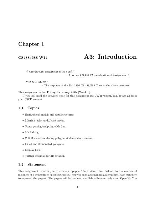
Chapter 1<br />
CS488/688 W14<br />
A3: Introduction<br />
“I consider this assignment to be a gift.”<br />
– A former CS 488 TA’s evaluation of <strong>Assignment</strong> 3.<br />
“NO IT’S NOT!!!”<br />
– The response of the Fall 1996 CS 488/688 Class to the above comment<br />
This assignment is due Friday, February 28th [Week 8].<br />
If you still need the provided code for this assignment run /u/gr/<strong>cs</strong>488/bin/setup A3 from<br />
your CSCF account.<br />
1.1 Topi<strong>cs</strong><br />
• Hierarchi<strong>ca</strong>l models and data structures.<br />
• Matrix stacks, undo/redo stacks.<br />
• Scene parsing/scripting with Lua.<br />
• 3D Picking.<br />
• Z Buffer and backfacing polygon hidden surface removal.<br />
• Filled and illuminated polygons.<br />
• Display lists.<br />
• Virtual trackball for 3D rotation.<br />
1.2 Statement<br />
This assignment requires you to create a “puppet” in a hierarchi<strong>ca</strong>l fashion from a number of<br />
instances of a transformed sphere primitive. You will build and manage a hierarchi<strong>ca</strong>l data structure<br />
to represent the puppet. The puppet will be rendered and lighted interactively using OpenGL. You<br />
1
2 CS488/688 Winter 2014 Introduction to Computer Graphi<strong>cs</strong><br />
will also build a user interface to selectively manipulate the joint angles of the puppet, and to<br />
globally rotate and translate the entire puppet. An undo/redo stack of joint transformations is<br />
maintained.<br />
The faces of the sphere primitive should be composed of filled rectangles (“quads” in OpenGL)<br />
to make it appear solid, and should be drawn using an OpenGL display list for maximum efficiency.<br />
Models <strong>ca</strong>n be displayed with Z-buffer, backface polygon culling, and frontface polygon culling; each<br />
of these three OpenGL features <strong>ca</strong>n be turned on and off. The final puppet should be drawn using<br />
a suitable selection of lights and materials so that the 3D structure of the puppet is obvious. The<br />
position of the light sources should be fixed relative to the <strong>ca</strong>mera.<br />
To create the puppet model, a sphere primitive should be appropriately transformed and instanced<br />
to create the torso (with its center as the origin of the puppet coordinate system). Smaller<br />
sphere instances for shoulders and hips should be positioned relative to this system. Their centres<br />
should form the origins for two secondary systems. With respect to the shoulder system, a<br />
neck sphere and two upper-arm spheres will form the origins of three subsidiary coordinate system<br />
origins. A sphere for the head will be positioned relative to the neck’s center, and each sphere<br />
for the forearm will be positioned relative to the upper arm’s center. The hands will be small<br />
spheres positioned relative to the forearms. The legs, consisting of thighs, <strong>ca</strong>lves, and feet, will be<br />
constructed similarly, with respect to the hip coordinate system.<br />
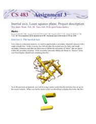
The general effect should be as shown:<br />
where the figure on the left shows all overlapping, s<strong>ca</strong>led spheres, and the figure on the right has<br />
hidden surfaces removed (your puppet need not have “pigeon toes”). The circle in the center of the<br />
face is a nose. You need at least one feature on the head so we <strong>ca</strong>n determine if rotations of the<br />
head are correct; it doesn’t have to be a nose. Feel free to add eyes, ears, hair, mouth, antennae,<br />
etc., to your puppet.<br />
You <strong>ca</strong>n be creative with your model, as long as it has the same or more degrees of freedom<br />
(number of joints) as this one. In the past people have built models of gorillas, dogs, Teddy bears,<br />
aliens, dinosaurs, gerbils, Oktoberfesters, etc. However, a “creative” model is not part of this
CS488/688 Winter 2014 Baranoski 3<br />
assignment’s requirements. Likewise you <strong>ca</strong>n add more modelling primitives if you want beyond<br />
the sphere, but it’s not a requirement.<br />
The coordinate system of each body part except the torso is therefore defined relative to a<br />
parent body part. The dependencies are as shown:<br />
Torso<br />
✘ ✘ ✘ ✘✘ ✘ ✘✘ ❳ ❳❳<br />
❳ ❳❳<br />
❳❳<br />
Shoulders<br />
Hips<br />
✘ ✘ ✘ ✘✘ ❳ ❳❳ ❳❳<br />
Left Upper Arm Right Upper Arm<br />
Neck<br />
Left Forearm Right Forearm<br />
Head<br />
Left Hand<br />
Right Hand<br />
✟ ✟✟ ✟<br />
Left Thigh<br />
Left Calf<br />
Left Foot<br />
❍❍<br />
❍<br />
❍<br />
Right Thigh<br />
Right Calf<br />
Right Foot<br />
The nose has been left out of this hierarchy as it is part of the Head body part.<br />
You are to implement primitives to build and render an arbitrary hierarchi<strong>ca</strong>l model. You will<br />
then write a Lua script to build a hierarchi<strong>ca</strong>l data structure to represent the puppet. Note the<br />
above structure is a physi<strong>ca</strong>l representation of which part of the body is connected to what, not<br />
the actual data structure. For the actual data structure, you will need additional intermediate<br />
“transformation nodes” for each body part to get the spheres properly hinged at the ends and for<br />
the joints. It’s also a good idea to not put children under nodes with nonuniform s<strong>ca</strong>les; create<br />
childless side branches instead. In particular, you will only want to put primitives at leaf nodes.<br />
The definition of the puppet is to include fifteen free angles, three for each arm and leg, and<br />
three for the head and neck. These angles will be used to animate the puppet. The three arm<br />
angles will set the amount of rotation of the upper arm forward about the shoulder, the amount of<br />
rotation of the forearm forward about the elbow, and the amount of rotation of the hand backward<br />
and forward about the wrist, in the same plane as the elbow and shoulder.<br />
The three leg angles will set the amount of rotation of the thigh forward about the hip, the<br />
amount of rotation of the <strong>ca</strong>lf downward about the knee, and the amount of rotation of the foot<br />
forward and backward about the ankle.<br />
Of the remaining three angles, one will set the amount of rotation of the base of the neck<br />
forward with respect to the torso/shoulder, one will set the amount of rotation of the base of the<br />
head forward with respect to the neck, and the last will set the rotation of the head to the right or<br />
left relative to the neck.<br />
All angles will have minimum and maximum values which the interface will enforce. For example,<br />
it should not be possible to rotate a knee or elbow the “wrong way”, or to rotate a hand or<br />
foot more than 90 degrees from its neutral position.<br />
Caution: In the past, students have found the creation of this model to be the most time<br />
consuming part of this assignment. You will probably want to design it on paper before writing<br />
the Lua code for the model.
4 CS488/688 Winter 2014 Introduction to Computer Graphi<strong>cs</strong><br />
1.3 Modelling<br />
You are to model your puppet using a Lua script. The next section describes the Lua/C++ interface<br />
you need to implement. First, we take a quick look at how the interface is organized.<br />
Lua is a simple scripting language. By using Lua to describe our scene we do not have to<br />
write a special-purpose parser for the scene. In C++, our scene will be represented as a number<br />
of SceneNode instances. Each SceneNode object has a transformation associated with it, and may<br />
have child nodes. There are two classes derived from SceneNode: JointNode and GeometryNode.<br />
These classes represent special types of nodes. Geometry nodes are nodes at which actual geometry<br />
is present (in this assignment, spheres). Joint nodes are nodes which <strong>ca</strong>n be manipulated in the<br />
user interface to rotate joints of the puppet.<br />
To begin constructing a puppet, we need a root for our modelling hierarchy. We <strong>ca</strong>n get one<br />
by asking for a transform node and assigning the result to a Lua variable. The name passed to the<br />
function is useful for debugging purposes.<br />
myroot = gr.node(’root’)<br />
Functions like gr.sphere create new geometry nodes.<br />
newly-created sphere a child of the root node:<br />
We <strong>ca</strong>n then use add child to make a<br />
torso = gr.sphere(’torso’)<br />
myroot:add_child(torso)<br />
You may wonder why we used a colon instead of a period in the last line. In Lua, “:” is used to<br />
<strong>ca</strong>ll member functions on objects and “.” is used to <strong>ca</strong>ll regular functions or class functions. We<br />
might then set the material properties of and transform the torso:<br />
torso:set_material(gr.material(...))<br />
torso:translate(1.0, 2.0, 3.0)<br />
Finally, we simply return the root node of the puppet:<br />
return myroot<br />
Conceptually, the transformation at a node is applied to both its geometry and its children,<br />
and matrices deeper in the tree are premultiplied by matrices higher in the tree. This assumes that<br />
column vectors are used to represent points.<br />
The tree given in the previous section just relates the pieces of the puppet. The tree you create<br />
for your program will need to have additional joint nodes, containing transformations and a joint<br />
rotation range. You will transform these “joint” nodes to animate your puppet. You may also need<br />
extra nodes to prevent child nodes from being affected by transformations meant to modify only<br />
the geometry of a parent node. Watch out, in particular, for s<strong>ca</strong>les. You generally will not want<br />
these in the middle of a chain of transformations.
CS488/688 Winter 2014 Baranoski 5<br />
1.4 The Interface<br />
The interface of your program should have at least a menu bar and a viewing area. The menu bar<br />
will have (at least) an Appli<strong>ca</strong>tion menu, an Edit menu, a Mode menu and an Options menu. In<br />
addition, when the graphi<strong>cs</strong> display is resized the aspect ratio should be properly maintained—the<br />
rendering of the puppet might change size, but its proportions should not become distorted.<br />
The Lua interface functions have been written for you, but they <strong>ca</strong>ll other functions which<br />
you will need to implement. Here is a list of Lua functions that have been implemented (in<br />
scene lua.cpp):<br />
• gr.sphere(name ) — Return a sphere with name name. The sphere should be centered at<br />
the origin with radius 1.<br />
• gr.node(name ) — Return a node name that just contains a transformation matrix, which<br />
is initialized to the identity matrix.<br />
• gr.joint(name, {xmin, xinit, xmax }, {ymin, yinit, ymax }) — Create a joint node<br />
with minimum rotation angles xmin and ymin, maximum rotation angles xmax and ymax<br />
and initial rotation angles xinit and yinit about the x and y axes.<br />
• onode:add child(cnode ) — Add cnode as a child of pnode.<br />
• gr.material({dr, dg, db }, {sr, sg, sb }, p ) — Return a material with diffuse reflection<br />
coefficients dr, dg, db, specular reflection coefficients sr, sg, sb, and Phong coefficient<br />
p.<br />
• node:set material(mat ) — Give the node node material mat.<br />
changed at any time.<br />
Node materials <strong>ca</strong>n be<br />
• node:rotate(axis, angle ) — Rotate node about axis (’x’, ’y’ or ’z’) by angle (in<br />
degrees).<br />
• node:translate(dx, dy, dz — Translate node by (dx, dy, dz).<br />
• node:s<strong>ca</strong>le(sx, sy, sz ) — S<strong>ca</strong>le node by (sx, sy, sz).<br />
You <strong>ca</strong>n partially verify your implementation with a3mark.lua and a3mark.png. The TAs will<br />
use this script to test some of the functionality of your assignment.<br />
Note that while the Lua-C++ interface for these commands is completely implemented for you<br />
(in scene lua.cpp), you will need to fill in the stubs in scene.cpp, and extend the scene data<br />
structures appropriately.<br />
1.4.1 Appli<strong>ca</strong>tion Menu<br />
The Appli<strong>ca</strong>tion menu should have the following items:<br />
Reset Position —Reset the origin of the puppet to its initial position. Keyboard shortcut I.<br />
Reset Orientation —Reset the puppet to its initial orientation. Keyboard shortcut O.
6 CS488/688 Winter 2014 Introduction to Computer Graphi<strong>cs</strong><br />
Reset Joints —Reset all joint angles, and clear the undo/redo stack. Keyboard shortcut N.<br />
Reset All —Reset the position, orientation, and joint angles of the puppet, and clear the undo/redo<br />
stack. Keyboard shortcut A.<br />
Quit —Terminate the program. Keyboard shortcut Q.<br />
1.4.2 Mode Menu<br />
The Mode menu should have the following radiobutton selections:<br />
Position/Orientation —Translate and rotate the entire puppet. Keyboard shortcut P.<br />
Joints —Control joint angles. Keyboard shortcut J.<br />
Initially, the program should be in the Position/Orientation mode.<br />
The behaviour of this interface is detailed in the following.<br />
Position/Orientation: The code in /u/gr/<strong>cs</strong>488/demo/trackball illustrates the interface you<br />
should implement for translating and rotating the puppet. You <strong>ca</strong>n use the trackball.c<br />
code here as a basis for your implementation.<br />
The following details the behavior of each mouse button. If you have questions about how<br />
this interface works, test intdemo and make your interface match it.<br />
• Dragging the mouse with B1 depressed changes the x and y translation of the puppet.<br />
• B2 depressed changes the z translation; moving the mouse up on the screen should move<br />
the puppet away from the viewer, while moving the mouse down on the screen should<br />
move the puppet closer.<br />
• Use B3 to implement a virtual trackball direct-manipulation-3D-orientation interface.<br />
The “virtual sphere” should be centered on the screen and its diameter should be 50%<br />
of the width or height of the raster widget, whichever is smaller.<br />
The skeleton code will display a circle centred on the screen. This circle corresponds<br />
to the virtual sphere. The radius of the circle will be a quarter of min(screen width,<br />
screen height).<br />
The translation should be done relative to the view frame. The rotation should also be performed<br />
relative to the view frame, translated to the puppet’s origin. Since in this assignment<br />
the view frame is fixed, you <strong>ca</strong>n make this easy by putting the <strong>ca</strong>mera in a simple <strong>ca</strong>noni<strong>ca</strong>l<br />
world-frame position. Rotating the puppet about its own origin <strong>ca</strong>n be done with an<br />
appropriate transform node above the torso.<br />
Joints: Clicking B1 is used as an event to signal picking. The cursor will be used with this signal<br />
to select a part of the puppet model.<br />
Selecting is regarded as a toggle operation. If an item is unselected, and it is picked, it will<br />
become selected. If the same item is picked again, it will become unselected. Selecting an<br />
item should <strong>ca</strong>use a visible change in the rendering of that item (change the material).
CS488/688 Winter 2014 Baranoski 7<br />
Only items that are directly under a movable joint should be selectable. When an item is<br />
selected, the joint immediately above it in the hierarchy will be affected by the user interface.<br />
If an item is not selectable, i.e. it is not immediately under a movable joint, picking it should<br />
do nothing. In particular, there should be no visible change in unselectable objects when they<br />
are picked.<br />
Multiple simultaneous selections should be permitted.<br />
For all selected items, the relative mouse y motion with B2 pressed will be mapped to the<br />
angles of the joint immediately above each selected object in the hierarchy. In addition, the<br />
head will rotate to the left and right with B3 depressed, in response to relative x motion of the<br />
mouse. It should be possible to depress both B2 and B3 simultaneously and simultaneously<br />
nod and rotate the head. The head should only move if it is selected, for both B2 and B3<br />
motions.<br />
1.4.3 Edit Menu<br />
The Edit menu should have the following items:<br />
Undo —undo the previous transformation on the undo/redo stack. Keyboard shortcut U.<br />
Redo —redo the next transformation on the undo/redo stack. Keyboard shortcut R.<br />
You should maintain an undo/redo stack of transformations. All joint transformations should<br />
be saved to the stack. The paradigm is that when you release a mouse button when in joint<br />
manipulation mode, the current joint angles are stored on the undo/redo stack. Initially, the stack<br />
contains the “reset” joint angles. If we think of the stack as extending upwards, you should maintain<br />
a current position in the stack. Selecting undo from the edit menu will restore the joint angles to<br />
the entry below the current one on the stack (and update the stack pointer to point at that entry).<br />
Selecting redo will update the joint angles to the entry above the current one on the stack (and<br />
update the stack pointer to point at that entry).<br />
If several joint transformations are undone, and a new joint transformation is initiated, all<br />
undo/redo entries above the current one should be cleared. If Reset All or Reset Joints are selected<br />
from the File Menu, the undo/redo stack should be cleared. You should provide reasonable feedback<br />
to indi<strong>ca</strong>te that an attempt to undo or redo past the end of the stack has been attempted (and not<br />
allow the action).<br />
1.4.4 Picking Menu<br />
The Picking menu should be implemented if you are unable to get selection with the mouse working<br />
properly (objective 3). Create a checkbox menu item for each selectable part. You will not get a<br />
mark for objective 3, but you will be able to implement and demonstrate joint movements.<br />
1.4.5 Options Menu<br />
The Options menu should have the following checkbox item:<br />
Circle —draws the circle for the trackball if checked. Keyboard shortcut C.
8 CS488/688 Winter 2014 Introduction to Computer Graphi<strong>cs</strong><br />
Z-buffer —draws the puppet with the OpenGL z-buffer if checked. Keyboard shortcut Z.<br />
Backface cull —draws the puppet with backfacing polygons removed. Keyboard shortcut B.<br />
Frontface cull —draws the puppet with frontfacing polygons removed. Keyboard shortcut F.<br />
All options should default to being “off”.<br />
1.5 OpenGL<br />
Most of what you need to learn about OpenGL is in the programming guide and man pages.<br />
However, here are a few items that are hard to find, and a few hints to make the assignment easier.<br />
None of the following are requirements on your program; they’re just hints that students in past<br />
terms have found helpful.<br />
• Unit normals. To get the lighting <strong>ca</strong>lculation correct, you must use unit normals. Although<br />
it is trivial to specify unit normals for the faces of the sphere, when you s<strong>ca</strong>le the sphere,<br />
the normals will also be s<strong>ca</strong>led, making them of non-unit length. To avoid this problem, use<br />
the appropriate glEnable command to tell OpenGL automati<strong>ca</strong>lly s<strong>ca</strong>le all normals to unit<br />
length.<br />
• Material properties. You <strong>ca</strong>n set ambient, diffuse, and specular material properties. For<br />
debugging purposes, it is probably easiest if you turn off the specular material properties (or<br />
rather, if you never turn them on).<br />
• Lights. For debugging purposes, it is easiest to have a single light source, placed at the eye.<br />
This will allow you to decide more easily if the shading of the puppet looks correct.<br />
• Normals, Colours, Vertices. When you give the glVertex command, OpenGL assigns the<br />
normal specified by the most recently issued glNormal command; likewise for glColor, which<br />
<strong>ca</strong>n be set up to modify the diffuse reflection colour when lighting is enabled.<br />
Thus, when specifying the normals and colours of the vertices, you must specify them BE-<br />
FORE you issue the glVertex command.<br />
You are required to use a display list to render the sphere. A display list is way of storing<br />
all vertices and normals as they are <strong>ca</strong>lculated so that OpenGL <strong>ca</strong>n reuse them rather than have<br />
to re<strong>ca</strong>lculate (and retransmit) them to OpenGL. This is sometimes <strong>ca</strong>lled “retained mode”, as<br />
opposed to the usual way of using OpenGL, which is “immediate mode”.<br />
Although you may use the gluSphere command if you want, you may want to generate the<br />
sphere yourself using sines and cosines, and drawing the sphere as a set of rectangles. For extra<br />
performance improvements, draw your puppet as a sequence of quad strips (this is not required,<br />
though). Regardless, you should select a resolution of the sphere that results in a good quality<br />
sphere while still allowing for smooth motion.
CS488/688 Winter 2014 Baranoski 9<br />
1.6 Donated Code<br />
In /u/gr/<strong>cs</strong>488/data/A3 you will find<br />
• appwindow.cpp – The appli<strong>ca</strong>tion window.<br />
• algebra.cpp – Routines for geometry, ferrets, etc.<br />
• main.cpp – The program entry point.<br />
• material.cpp – Classes and functions for manipulating materials.<br />
• primitive.cpp – Classes and functions for manipulating geometric primitives such as spheres,<br />
etc.<br />
• scene.cpp – Classes and functions defining modelling hierarchies. The layout of these classes<br />
should provide some ideas about how to organize your code.<br />
• scene lua.cpp – The Lua/C++ interface.<br />
• viewer.cpp – The GTK+ OpenGL viewer widget.<br />
• Makefile – Used to build the program.<br />
• a3mark.lua – A Lua script to test your implementation.<br />
• a3mark.png – An image showing what the screen output of a3mark.lua should look like.<br />
These files have been copied to your handin/A3 directory. You should also use trackball.c which<br />
you <strong>ca</strong>n find in /u/gr/<strong>cs</strong>488/demo/trackball.<br />
Note that the matrix multipli<strong>ca</strong>tion routines are not needed for rendering, only to set up the<br />
matrices in the nodes.<br />
1.7 Deliverables<br />
Executables:<br />
The following two files are to be in your A3/ directory:<br />
puppeteer - Your puppet viewer. This program should take a single argument specifying a<br />
Lua puppet file to load. If no arguments are given it should load puppet.lua from the<br />
current directory.<br />
puppet.lua - Your puppet.<br />
The supporting source code should also be available in the src directory.<br />
Don’t forget screenshot01.png.<br />
Documentation:<br />
• Document changes you make to the data structure.<br />
• Document the structure of the hierarchi<strong>ca</strong>l model of your puppet.<br />
For this assignment, you are encouraged to make creative models. The instructor and TAs may<br />
assign up to 1 bonus mark for interesting puppets.
10 CS488/688 Winter 2014 Introduction to Computer Graphi<strong>cs</strong><br />
1.8 Objectives: <strong>Assignment</strong> 3<br />
Due: Friday, February 28th [Week 8].<br />
Name:<br />
UserID:<br />
<strong>Student</strong> ID:<br />
1: a3mark.lua runs and displays correctly.<br />
2: The puppet’s proportions are reasonable and the spheres are joined together in a logi<strong>ca</strong>l<br />
fashion. The spheres are “hinged” to their neighbours at their ends—they do not rotate<br />
about their centres.<br />
3: Picking works correctly and reliably.<br />
4: Selection records are kept correctly so that any sequence of picks-to-select and picks-tounselect<br />
works. Multiple selections are supported. Selected portions of the puppet are clearly<br />
indi<strong>ca</strong>ted—e.g. selected parts change colour, or their edges are highlighted.<br />
5: The puppet <strong>ca</strong>n be globally rotated and translated for viewing purposes. The rotation user<br />
interface is a virtual trackball. A circle representing the virtual sphere <strong>ca</strong>n be turned on or off<br />
from the menu. It must be clearly visible when it is turned on. The puppet’s configuration<br />
<strong>ca</strong>n be reset from the menu.<br />
6: A well-designed hierarchi<strong>ca</strong>l data structure is employed. Each sphere is drawn as an instance<br />
of a single display list sphere.<br />
7: The joint movements are correct and the angles are restricted so that no grossly unnatural<br />
configurations are allowed. The puppet does not fly apart or distort during any sequences or<br />
combinations of actions.<br />
8: Z-buffer, backfacing and frontfacing polygon hidden surface removal are implemented and<br />
each <strong>ca</strong>n be toggled on and off.<br />
9: The puppet is lit such that its 3D structure is clearly visible.<br />
10: An undo/redo stack is maintained.<br />
Declaration:<br />
I have read the statements regarding cheating in the CS488/688 course handouts. I<br />
affirm with my signature that I have worked out my own solution to this assignment,<br />
and the code I am handing in is my own.<br />
Signature:
CS488/688 Winter 2014 Baranoski 11<br />
CS 488/688 Copyright permission for <strong>Assignment</strong> 3<br />
✷ I grant permission to use images of my <strong>Assignment</strong> 3 in the course webpage and/or t-shirt.<br />
I realize that I <strong>ca</strong>n revoke this permission for use in the webpage at any time by requesting so in<br />
writing or by email.<br />
✷ I do NOT grant permission to use images of my <strong>Assignment</strong> 3 in the course webpage or<br />
t-shirt.<br />
Name (printed):<br />
<strong>Student</strong> id:<br />
User id:<br />
Signature:<br />
Date: