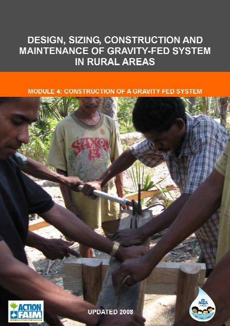
Module 4 - Construction of a gravity fed system
Module 4 - Construction of a gravity fed system
Module 4 - Construction of a gravity fed system

Create successful ePaper yourself
Turn your PDF publications into a flip-book with our unique Google optimized e-Paper software.
2007 UPDATE
CONTENTS<br />
CONTENTS .........................................................................................................................1<br />
I. INTRODUCTION ..........................................................................................................2<br />
II.<br />
CHOICE AND USE OF MATERIALS...........................................................................3<br />
II.1. MATERIALS .........................................................................................................................3<br />
II.2.<br />
CONCRETE...........................................................................................................................5<br />
II.3. REINFORCED CONCRETE .............................................................................................11<br />
II.4.<br />
MASONRY...........................................................................................................................18<br />
II.5. GABION ...............................................................................................................................20<br />
III.<br />
CONSTRUCTION OF THE INFRASTRUCTURES COMPOSING A GFS..............22<br />
III.1. SPRING CATCHMENT .....................................................................................................22<br />
III.2. STORAGE TANK................................................................................................................26<br />
III.3. HEADER TANK AND BREAK PRESSURE TANK.......................................................33<br />
III.4. TAPSTAND ..........................................................................................................................39<br />
III.5. PIPELINES...........................................................................................................................46<br />
III.6. WORK DURATION AND MANPOWER ........................................................................58<br />
1
I. INTRODUCTION<br />
The construction <strong>of</strong> a GFS involves the construction <strong>of</strong> various infrastructures as well as<br />
installation <strong>of</strong> pipeline. It is an important step that requires the use <strong>of</strong> construction<br />
techniques that should be implemented carefully if you do not want to have problems when<br />
the GFS is functioning. It is essential to use good quality construction materials mixed with<br />
the good proportions if we want to realize resistant and sustainable civil works.<br />
Today the majority <strong>of</strong> the infrastructures composing a GFS are built with reinforced<br />
concrete because <strong>of</strong> its robustness and stability. Indeed, the reinforced concrete <strong>of</strong>fers<br />
good resistance to the high temperatures, vibrations and heavy loads. The infrastructures <strong>of</strong><br />
a GFS generally built using reinforced concrete are the spring catchment, header tank, break<br />
pressure tank, storage tank and tapstand.<br />
The objective <strong>of</strong> this module is to provide the necessary minimum knowledge on the main<br />
construction materials to be used, as well as the technical implementation <strong>of</strong> various works<br />
composing a GFS.<br />
2
II.<br />
CHOICE AND USE OF MATERIALS<br />
II.1. MATERIALS<br />
Materials used for the construction <strong>of</strong> the various infrastructures composing a GFS are as<br />
follows:<br />
Cement - Sand - Gravel - Stone - Brick - Iron bars - Water.<br />
II.1.1.<br />
Cement<br />
Cement is a hydraulic binder used to combine elements such as sand and gravel. Good quality<br />
cement consists <strong>of</strong> fine powder and was stored in a dry place (if it is stored in a humid place,<br />
it will lose its binder properties).<br />
The cement usually used by ACF in Indonesia (and especially in NTT province) is<br />
• Tonasa (companies belonging to government) for work requiring a very good quality <strong>of</strong><br />
cement<br />
• Bosowa (from Sulawesi) for work requiring a lower quality cement<br />
In NTT, ACF do not advice to use the cement brand “Kupang”, which has a poor quality.<br />
Cement can be used to make:<br />
1. Mortar = cement + sand + water.<br />
Used for masonry, plastering, and various type <strong>of</strong> sealing.<br />
2. Masonry = mortar + large elements (bricks or stones).<br />
Used mainly for retaining walls construction. Masonry can also be used for the<br />
construction <strong>of</strong> tapstand, valve box and spring catchments, when the gravel is not<br />
available on the spot and/or the distances to be covered by foot to bring gravel would be<br />
too important.<br />
3. Concrete = cement + sand + gravel + water<br />
Used for the manufacture <strong>of</strong> a great number <strong>of</strong> works like spring catchments, tanks,<br />
tapstand and header tank.<br />
4. Cement milk= cement + water<br />
Used only for plastering and ensuring the water tightness <strong>of</strong> concrete (to be used after<br />
several layers <strong>of</strong> mortar for finishing touch). It does not have any internal resistance to<br />
load.<br />
II.1.2.<br />
Gravel<br />
Gravel is a natural material collected from quarries, made out <strong>of</strong> crushed stones, or<br />
extracted from riverbeds. For the construction, river gravel (round and polished shape) is<br />
preferred to crushed gravel.<br />
3
Gravel is used only in the making <strong>of</strong> concrete. The size <strong>of</strong> gravel to be used must vary<br />
according to the thickness <strong>of</strong> the construction and the desired type <strong>of</strong> reinforced concrete.<br />
To obtain a watertight concrete, ACF recommends a size <strong>of</strong> gravel from 6 to 25mm.<br />
Generally, for concrete construction, size <strong>of</strong> gravel must be lower than 1/5 <strong>of</strong> the thickness<br />
<strong>of</strong> the construction. River gravel must be sieved to obtain desired granulometry.<br />
II.1.3.<br />
Sand<br />
Sand is extracted from riverbeds or beaches (but then sands need to be cleaned carefully<br />
with fresh water to remove the salt, to avoid the iron bar to become quickly corroded inside<br />
the concrete) and sand grain have generally a diameter lower than 5mm. Sand is used to make<br />
mortar as well as concrete. To obtain a good quality construction, sand must be clean (all<br />
impurities such as soil, clay, leaves, etc. must be removed) and solid.<br />
The size <strong>of</strong> the grains is also important: if the sand grains are too fine, it will weaken the<br />
concrete. To obtain a watertight concrete, ACF recommends using sand grain size from 0.1 to<br />
5mm.<br />
II.1.4.<br />
Stones<br />
Stones are used for constructions for masonry, foundations and the making <strong>of</strong> gabions.<br />
Stones must be imperatively clean and solid. It is necessary to avoid the weathered stones<br />
that can crumble or break easily.<br />
II.1.5.<br />
Brick<br />
Bricks are used only for masonry. Bricks are made out <strong>of</strong> clay, or similar substances<br />
containing silica. Bricks that can be found in Indonesia are <strong>of</strong> baked clay, solid, and <strong>of</strong> have<br />
usually a size <strong>of</strong> 20cm x 10cm x 5cm. In NTT province, they usually are 15cm x 10cm x 5cm.<br />
II.1.6.<br />
Reinforcement bars<br />
Reinforcement bars are used for the making <strong>of</strong> reinforced concrete. Two types <strong>of</strong> bars can<br />
usually be found on the market:<br />
• High-adhesion reinforcement bars, known as HA bars, which have serrations to ensure<br />
better adhesion to the concrete. However, in Indonesia, due to their high price, ACF<br />
usually does not use them for simple GFS work. However, for sensitive work such as<br />
dam or large size reservoirs, it is compulsory to use them. Bar are initially 10m long<br />
and diameter <strong>of</strong> 10, 12, 14, 16, 20, 25mm can be purchased.<br />
• Smooth reinforcement bars. They present a lower adhesion to concrete then the HA<br />
bars, so they require greater anchorage lengths. Bars are initially 10m long and<br />
diameter <strong>of</strong> 6, 8, 10, 12mm can be purchased.<br />
For the same diameter, if there is no budget constraint, high-adhesion reinforcement bars<br />
will be preferred to smooth bars because <strong>of</strong> their serrations, which guarantee a better<br />
adherence with the concrete.<br />
4
To ensure a good adherence, it is important that bars have a clean surface, free from organic<br />
substances, oil, rust, etc.<br />
Steels <strong>of</strong>fer a good resistance to tension stress. The resistance <strong>of</strong> the reinforcement bars<br />
depends on their manufacture process, but has generally the values indicated in table 1:<br />
Type <strong>of</strong> steel<br />
Table 1: Resistance <strong>of</strong> reinforcement bars<br />
Quality<br />
(international<br />
standard)<br />
Max tensile resistance<br />
(tension for which steel<br />
yields)<br />
Smooth bar RS 24 2,400 kg/cm 2<br />
High-Adherence<br />
bar<br />
SD 30<br />
SD 40<br />
3,000 kg/cm 2<br />
4,000 kg/cm 2<br />
In Indonesia, two main types <strong>of</strong> smooth bars are available:<br />
• “Standard”. You can find precise diameter (6mm, 8mm etc…). Length is 12 m. They are<br />
one recommended by ACF<br />
• “Banci”. The diameters available are not precise, and the length <strong>of</strong> bars are not<br />
standard.<br />
II.1.7.<br />
Water<br />
Water is used in the making <strong>of</strong> mortars and concretes. The use <strong>of</strong> water has several<br />
functions: it allows hydrating cement, wetting the aggregates and ensuring a sufficient<br />
plasticity to the mixture obtained. Cement hydration is the name given to the chemical<br />
reaction that causes a phenomenon <strong>of</strong> solidification and hardening when water is added. To<br />
ensure a good cement hydration, water must be imperatively clean and contains no impurity.<br />
II.2. CONCRETE<br />
II.2.1.<br />
Introduction<br />
Concrete is a mix <strong>of</strong> cement, gravel, sand and water. Thanks to water and cement, this<br />
mixture hardens during its curing period and becomes very resistant to compression stress<br />
(see table 2).<br />
The resistance <strong>of</strong> a concrete depends mainly on the quality <strong>of</strong> materials used and their<br />
proportion. A mix with more cement gives a higher resistance to compression stress (see<br />
table 3), but the risk <strong>of</strong> formation <strong>of</strong> cracks during the curing period <strong>of</strong> the concrete<br />
increases.<br />
5
Table 2: Increase <strong>of</strong> concrete resistance during hardening period.<br />
Duration (day)<br />
% <strong>of</strong> total<br />
resistance<br />
3 20<br />
17 45<br />
28 60<br />
3 months 85<br />
6 months 95<br />
1 year 100<br />
Table 3: Variation <strong>of</strong> concrete resistance during 28 days according to the quantity <strong>of</strong> cement<br />
added to the mix.<br />
Cement<br />
Proportioning<br />
(kg/m 3 )<br />
Resistance to<br />
Compression<br />
(kg/cm 2 )<br />
Resistance to<br />
tension<br />
(kg/cm 2 )<br />
300 210 20<br />
350 250 22<br />
400 280 24<br />
II.2.2.<br />
Mixing the concrete<br />
The proportions <strong>of</strong> the concrete mixture and the amount <strong>of</strong> required materials necessary to<br />
obtain 1 m 3 <strong>of</strong> concrete are given in table 4.<br />
Type <strong>of</strong> concrete<br />
Table 4: Proportions <strong>of</strong> concrete mix<br />
Cement<br />
(kg)<br />
Sand (L)<br />
Gravel (L)<br />
Anglo-Saxon<br />
denomination<br />
Traditional 350 400 800 1 : 2 : 4<br />
Foundation 200 – 250 400 800 1:2.5:5<br />
Special works<br />
(for example hand dug well’s<br />
cutting edge)<br />
400 400 800 1 : 1.5 : 3<br />
6
The Anglo-Saxon denomination such as “1:2:4” is valid only on volume (1 volume <strong>of</strong> cement for 2 volume<br />
<strong>of</strong> sand and 4 volume <strong>of</strong> gravel), but not for mass (kg). Volume can be measured with buckets. But be<br />
careful, a bag <strong>of</strong> 40kg <strong>of</strong> cement does not correspond to 40L. It should be known that:<br />
• The density <strong>of</strong> cement is 1,440 kg/m3 and 1m3 = 1000L<br />
• So, using the rule <strong>of</strong> proportionality on the right side, a bag <strong>of</strong> cement <strong>of</strong><br />
40kg represent X = 40 * 1000 / 1,440 = 28 L<br />
• On the same way, you can calculate that a the volume represented by a<br />
50kg bag <strong>of</strong> cement is X = 50 * 1,000 / 1,440 = 35 L<br />
• On the same way, 350kg <strong>of</strong> cement correspond to 250L, or 7 bags <strong>of</strong> 40kg<br />
1,440 kg 1,000L<br />
40 kg X L<br />
This proportionality rule can be used for many other purposes.<br />
Remark: the correspondence between mass and volume is only true for pure water, which has a density<br />
<strong>of</strong> 1000 kg/m 3 (or 1kg/L), so 1L <strong>of</strong> water = 1kg<br />
It is necessary to pay attention to the fact that when expended, aggregates <strong>of</strong> 1m 3 will<br />
correspond to 1.2 m 3 . To obtain 1m 3 <strong>of</strong> concrete using a traditional mix (1:2:4), it would be<br />
necessary to put 350 kg ( = 250L) <strong>of</strong> cement, 500 liters <strong>of</strong> sand and 1000 liters <strong>of</strong> gravel. But<br />
when mixed, this would represent more than 1m3. So the initial quantities <strong>of</strong> sand and gravel<br />
must be divided by 1.2 (500L <strong>of</strong> sand become 400L, and 1000L <strong>of</strong> gravel becomes 800L).<br />
In the villages the buckets used to measure the quantities <strong>of</strong> sand and gravel are generally 5<br />
liters.<br />
Example <strong>of</strong> calculation <strong>of</strong> a simple concrete structure:<br />
To make this traditional concrete construction: How much cement bag <strong>of</strong> 40 kg do we need?<br />
How much 5L sand buckets do we need?<br />
How much 5L gravel buckets do we need?<br />
7
Result:<br />
• Calculate the volume <strong>of</strong> the structure: V = (2 x 1.5 x 0.3) + ((3-0.3) x 1.5 x 0.3) = 2.12 m3<br />
• Calculate number <strong>of</strong> cement bags necessary: 2.12 x 350 = 742 kg <strong>of</strong> cement = 18.6 bags<br />
<strong>of</strong> 40kg cement. We thus need approximately 19 cement bags <strong>of</strong> 40kg.<br />
• Calculate the quantity <strong>of</strong> sand necessary: 2.12 x 400 = 848 liters <strong>of</strong> sand, or 170<br />
buckets <strong>of</strong> 5L.<br />
• Calculate the quantity <strong>of</strong> gravel necessary: 2.12 x 800 = 1,696 liters <strong>of</strong> gravel, or 340<br />
buckets <strong>of</strong> 5L.<br />
It is important to underline that the quantities calculated are theoretical. The quantities<br />
really used on site are <strong>of</strong>ten higher because <strong>of</strong> the losses. We thus add generally 10% to<br />
quantities calculated to have the required quantities on site.<br />
II.2.3.<br />
Implementation and precautions<br />
You have to work on an arranged surface (cemented ground, metallic plate…) where you first<br />
add cement, then sand then gravel, by moving the heaps each time. Once a homogeneous<br />
mixture is obtained, give the mix a “volcano” shape in which you pour the suitable quantity <strong>of</strong><br />
water; it is important to let to the water the time to diffuse before mixing, which will give to<br />
the concrete its plasticity. A good concrete must be well mixed.<br />
The concrete consistency depends on the quantity <strong>of</strong> water used. The more liquid is the<br />
concrete, the easiest it is to handle, but the lower will be its resistance once dry. It is thus<br />
necessary to define the water content according to the desired use <strong>of</strong> the concrete, and to<br />
obtain the right balance so that the material is at the same time resistant enough and easy<br />
to handle. The table 5 gives the estimation <strong>of</strong> the water quantity required to make 1m 3 <strong>of</strong><br />
concrete, according to the desired quality <strong>of</strong> concrete:<br />
Concrete quality<br />
Water volume<br />
(liter) for 350 kg <strong>of</strong><br />
cement<br />
Concrete resistance<br />
at 28 days<br />
(kg/cm 2 )<br />
Ratio liter <strong>of</strong> water<br />
/ kg <strong>of</strong> cement<br />
Very firm 151 330 0.43<br />
Firm 175 280 0.5<br />
Plastic 200 240 0.57<br />
S<strong>of</strong>t 221 210 0.63<br />
Very s<strong>of</strong>t 231 190 0.66<br />
For example, to obtain a firm concrete, you use a ratio water (L) / cement (kg) <strong>of</strong> 0.5, which<br />
means that for a bag <strong>of</strong> cement <strong>of</strong> 40kg, you should add 40 * 0.5 = 20L <strong>of</strong> water. If you want<br />
a s<strong>of</strong>t quality concrete, use a ration <strong>of</strong> 0.63, so for a 40kg bag <strong>of</strong> cement you should use 40 *<br />
0.63 = 25.2L <strong>of</strong> water.<br />
The water quantity to be used for concrete preparation also intervenes in the phenomenon<br />
called segregation, i.e. loss <strong>of</strong> homogeneity <strong>of</strong> the material, leading to loss <strong>of</strong> resistance.<br />
Indeed, if the necessary precautions are not taken, the concrete components, being <strong>of</strong> very<br />
8
different granulometry (gravels, sand, and cement), tends to separate: the heaviest ones at<br />
the bottom, lightest ones on the top.<br />
Once the mixture is ready, fill the formwork. The filling must be made quickly, and should not<br />
exceed 2 meters height. While filling the formwork, the concrete must be vibrated to free<br />
the imprisoned air to make the concrete more compact and solid.<br />
The hardening <strong>of</strong> the concrete is improved by moisture and high temperatures. Under normal<br />
conditions, we can make the following estimation:<br />
o 30 minutes until 1 hour for the setting:<br />
o 4 hours until the end <strong>of</strong> the setting: the concrete cannot be worked anymore,<br />
o The concrete then start the hardening phase, which can last 6 months to 1 year to be<br />
completed.<br />
The curing phase is a very important step that must be carried out carefully because it is<br />
during this phase that the concrete hardens. We must ensure that the concrete dries slowly,<br />
by moisturizing it regularly. Indeed, the concrete curing requires a certain humidity level so<br />
that the chemical hardening reaction is as slow as possible. It is important to underline that<br />
to moisture again a concrete that is already a slightly dry is not advisable. If the cement<br />
already dried, even slightly, without enough moisture, it has become crumbly, and to add<br />
water will not allow the cement to recover the hardness that it has already lost, since the<br />
chemical reaction <strong>of</strong> hardening has already taken place.<br />
When the concrete is rather hard, you can remove the formwork. For the construction <strong>of</strong><br />
infrastructures, formwork can be generally removed after 24 hours. For the infrastructure<br />
such as large reservoir for which the construction requires several steps, one step can be<br />
made each day. It is necessary to distinguish between the waiting time before removing the<br />
formwork (roughly 24h), and the waiting time before using the infrastructure, which is<br />
generally <strong>of</strong> 28 days (before filling a reservoir with water, for example).<br />
To obtain a good quality concrete, the following precautions should be taken:<br />
• To avoid important contraction and segregation <strong>of</strong> the concrete, never add too much<br />
water to the mix<br />
• Always protect the concrete from the sun and wind (cover the concrete with plastic<br />
sheeting, cement bags, bamboo mat...) and always moisturize all the surfaces and the<br />
formwork to ensure a slow drying,<br />
• Always respect formwork removal times and the waiting time before using the<br />
infrastructure,<br />
• Never wait more than 24 hours between two successive concrete pours. The surface<br />
between the two parts should be cleaned and rough.<br />
• Vibrate vigorously the concrete to make it compact, but do not vibrate too long to avoid<br />
segregation.<br />
Good joints between two successive concrete pours are very important for the solidity and<br />
impermeability <strong>of</strong> the work. The conditions for a good joint are: a correct angle <strong>of</strong> joint, a<br />
well-prepared contact surface as well as a very short delay between two successive pours.<br />
(see table 6). The correct angle <strong>of</strong> joint varied depending on the type <strong>of</strong> stress undergone by<br />
the structure (see figure 1). For a load bearing wall or partition wall under vertical stress,<br />
joints are perpendicular, whereas for a floor or water tank wall (thus with horizontal effort),<br />
9
angle sides are preferable. To guarantee a good adhesion, it is necessary to roughen the<br />
surface (with a chisel for example) to provide a key. Then we brush the rough surface to<br />
remove rubble and dust, and we moisture it before pouring the next concrete.<br />
Table 6: Resistance <strong>of</strong> the joint between 2 parts <strong>of</strong> the infrastructure that were concreted<br />
at a different time<br />
Delay between<br />
successive pours<br />
Joint resistance<br />
1 day 325 kg/cm 2<br />
7 days 210 kg/cm 2<br />
18 days 65 kg/cm 2<br />
Fig.1: Joint angle depends on the direction <strong>of</strong> the main stress undergone by the structure.<br />
To improve the quality <strong>of</strong> the concreting process, it is possible to add chemical additives.<br />
There are a great number <strong>of</strong> additives for the concrete: water pro<strong>of</strong>ing agent, setting<br />
accelerator, liquefier and plastifier…<br />
For the construction <strong>of</strong> spring catchments and tanks, two problems <strong>of</strong>ten occurs:<br />
The foundation <strong>of</strong> the catchment needs to be done under the water. By using a<br />
traditional mix <strong>of</strong> concrete, there is a risk that the concrete will be washed away<br />
before getting dry. It is necessary to add to the mix an additive that will accelerate<br />
the setting. If no additive is present, then try to divert the flow <strong>of</strong> the spring using<br />
planks for all the concrete setting duration.<br />
Traditional mix <strong>of</strong> concrete is not 100% water tight (and even porous if not enough<br />
sand is added to the mix). For the infrastructures that requires a high level <strong>of</strong> water<br />
tightness, it is necessary to add specific cement additive that will increase the usual<br />
10
water tightness <strong>of</strong> the concrete. If no additive is available, you can use a higher<br />
quality cement, or a mix <strong>of</strong> concrete containing more cement than usual.<br />
ACF has identified several types <strong>of</strong> cement additives in Indonesia:<br />
• In NTT, the cement additive easily available in Kupang and used by ACF is called<br />
ADDITON H.E. SPECIAL. It is available in 1.25kg plastic can, for around 20,000 Rp. It<br />
cumulates three properties, with different dosage according to the use:<br />
o Fast hardening (in 7 days the conceret has the same resistance as in 28 days)<br />
o Improved quality <strong>of</strong> concrete(80cm 3 /cement bag <strong>of</strong> 50kg)<br />
o Making water pro<strong>of</strong> concrete (200cm 3 /cement bag <strong>of</strong> 50kg<br />
• “Damdex”: widely available and used by civil work contractors in Jakarta and Java. This<br />
additive is expensive (40,000 Rp / 1L bottle) but combines three properties:<br />
accelerated hardening, increased water tightness and increased binding effect and<br />
concrete resistance. The proportions are different according to the use:<br />
o To block a leaking hole, use 1 volume <strong>of</strong> Damdex for 3.5 volume <strong>of</strong> cement, and<br />
do not add any water.<br />
o For waterpro<strong>of</strong> wall/slab coating, use 1 volume <strong>of</strong> Damdex for 2 volume <strong>of</strong><br />
cement and 1 volume <strong>of</strong> water, and apply two layers <strong>of</strong> the mixture.<br />
o For solid, fast drying and better waterpro<strong>of</strong> concrete, use 0.5% to 2% <strong>of</strong><br />
Damdex per weight <strong>of</strong> cement, according to the required strength, and add it<br />
to the mix.<br />
• A lot <strong>of</strong> products <strong>of</strong> the civil work company SIKA are available in Jakarta and Surabaya.<br />
They <strong>of</strong>fer a wide range <strong>of</strong> product, like for example:<br />
o “SikaCim Accelerator”, for accelerated hardening (can be used for exemple to<br />
block a leak while water is running out <strong>of</strong> it)<br />
o “Sika Multiseal”, for increased water tightness<br />
II.3. REINFORCED CONCRETE<br />
The reinforced concrete consists <strong>of</strong> concrete and steel bars: it presents thus a combination<br />
between the physical properties <strong>of</strong> these two materials: resistance to compression effort <strong>of</strong><br />
the concrete and resistance <strong>of</strong> tension effort <strong>of</strong> the steel. Reinforced concrete<br />
infrastructures are very resistant, and also economical because it requires small thickness <strong>of</strong><br />
concrete (thus less cement, sand gravel etc…).<br />
II.3.1.<br />
Reinforcement<br />
To reinforce the concrete, you must add inside steel bars to create a reinforcement: steels<br />
bars are positioned to undergo the tension stress and to distribute the stress evenly inside<br />
the structure. Iron wire is used to bind steels bars between them.<br />
11
We differentiate steels bars according to their role:<br />
• Main steels: they are located in the zones <strong>of</strong> tensile stress (areas <strong>of</strong> tensil stress are<br />
usually located on the opposite side <strong>of</strong> the side where the stress is applied, as shown in<br />
the figure on the right)<br />
• Distribution steels: they distribute evenly the efforts, limit the risk <strong>of</strong> cracks and<br />
facilitate the assembly <strong>of</strong> the main steels,<br />
The transmission <strong>of</strong> the stresses from concrete to steel bars and vice versa is done thanks<br />
to the adherence <strong>of</strong> the steel bars. To guarantee the good adherence between concrete and<br />
steel bars, it is necessary to:<br />
- Have a clean surface<br />
- Ensure a good vibration <strong>of</strong> the concrete when pouring it<br />
- Respect a sufficient length <strong>of</strong> anchorage <strong>of</strong> steels inside the concrete<br />
- Ensure that the bars inside the concrete are located at more than 3cm from the<br />
surface.<br />
The anchoring lengths to be respected are as follows:<br />
- Steel bars must overlap in the concrete over a minimum length L, called anchoring lenght:<br />
Curved<br />
Non-curved<br />
L depends on ø = diameter <strong>of</strong> the bar:<br />
High<br />
adherence<br />
steel bar<br />
Smooth<br />
steel bar<br />
Curved L = 30 x ø L = 40 x ø<br />
Non-curved L = 50 x ø L = 60 x ø<br />
12
- The angle <strong>of</strong> the anchoring curves must be done in the following way:<br />
- The anchoring lengths at the edges that undergo bending moment or tensile stresses must<br />
be as follows:<br />
a = wall length / 4<br />
= minimum 15 - 20 cm<br />
= minimum 40 cm for tanks<br />
II.3.2.<br />
Framework scheme<br />
The objective <strong>of</strong> this paragraph is to give general information regarding the design <strong>of</strong> the<br />
framework (= reinforcement bars scheme) <strong>of</strong> various types <strong>of</strong> reinforced concrete<br />
infrastructures.<br />
A more detailed framework scheme will be given in the following chapter (chapter III) for<br />
each reinforced concrete infrastructures usually needed for a GFS.<br />
→ Slab<br />
13
The slab thickness (e) must be at least 7cm. In general, we can give the following values for<br />
the thickness:<br />
- Slab on 2 walls: e = from 1/20 to 1/30 <strong>of</strong> the span,<br />
- Slab on 4 supports: e = 1/20 <strong>of</strong> the span,<br />
- Slab on 4 walls: e = from 1/30 to 1/40 <strong>of</strong> the span.<br />
Main steels are located as follows:<br />
• Above the slab for an apron ( = floor slab), except in the tanks case because <strong>of</strong> the<br />
vertical pressure created by water,<br />
• At the bottom <strong>of</strong> the slab for a cover slab or an elevated slab<br />
→ Pillars<br />
As rough sizing we will take as a<br />
minimum:<br />
a = 1/20 <strong>of</strong> the beam height<br />
→ Foundations<br />
14
→ Circular tank<br />
Horizontal reinforcement (circles) is essential to resist to the pressure exerted by water on<br />
the walls <strong>of</strong> this type <strong>of</strong> tanks. In the case <strong>of</strong> water storage tanks, the more you go to the<br />
top <strong>of</strong> the tank’s wall, the lower is the pressure <strong>of</strong> water against the wall, so the bigger<br />
should be the space between reinforcements (however, you should not increase the space<br />
between the circles more than three times the wall thickness).<br />
For the reinforcement <strong>of</strong> circular tanks <strong>of</strong> important capacity, you can use the same<br />
configuration as for rectangular tanks <strong>of</strong> important capacity (see below).<br />
→ Rectangular Tank<br />
Horizontal cross-section <strong>of</strong> walls reinforcement:<br />
For the small tanks (wall length lower than 2m) we use the following configuration, with<br />
minimum a = 40cm:<br />
15
For the rectangular tank <strong>of</strong> important capacity, we use the following framework<br />
configuration:<br />
II.3.3.<br />
Reinforcements sizing<br />
Generally, we can estimate the necessary quantity <strong>of</strong> steel bars the following way:<br />
- 75 - 90 kg <strong>of</strong> steel bars each m 3 <strong>of</strong> concrete,<br />
- 15 kg <strong>of</strong> wire per ton <strong>of</strong> steel bar<br />
For the traditional GFS infrastructures such as spring catchments, header tank, tapstand<br />
and break pressure tank, the sizing <strong>of</strong> the steel reinforcement (diameter and mesh) is always<br />
more or less the same because the dimensions <strong>of</strong> these infrastructures never change a lot.<br />
The standard reinforcements sizing for this type <strong>of</strong> infrastructures will be given in the<br />
following chapter (chapter III).<br />
On the other hand, for the storage tanks, reinforcement sizing depends on the capacity <strong>of</strong><br />
the tank and can vary greatly according to the flow <strong>of</strong> the spring and the number <strong>of</strong> people to<br />
be covered. It is thus essential to know how to size precisely the framework for this type <strong>of</strong><br />
infrastructure. Tables that allow sizing circular and rectangular storage tank are given in the<br />
following paragraphs,<br />
16
→ Circular tank<br />
- Horizontal reinforcement by sections <strong>of</strong> 1 meter starting from the top<br />
Wall thickness (cm)<br />
Diameter (m)<br />
10 cm<br />
1.5 - 2 m<br />
10 cm<br />
2 – 2.5 m<br />
10 cm<br />
2.5 - 3 m<br />
10 cm<br />
4.5 - 5 m<br />
10 cm<br />
6 m<br />
Height* (m)<br />
Diameter <strong>of</strong> irons used (mm) and mesh (cm)<br />
0 – 1 m Ø8 / 25 Ø8 / 25 Ø8 / 25 Ø8 / 25 Ø8 / 25<br />
1 – 2 m Ø8 / 25 Ø8 / 25 Ø8 / 25 Ø8 / 15 Ø10 / 17.5<br />
2 – 3 m Ø8 / 15 Ø8 / 15 Ø10 / 12.5 Ø12 / 15<br />
3 – 4 m Ø8 / 15 Ø12 / 12.5 Ø12 / 10<br />
* by choosing a given height we can calculate easily the tank capacity:<br />
capacity = height x 3.14 x r 2 = height x 3.14 x diameter 2 / 4<br />
Standard examples <strong>of</strong> tank capacity are given to the following table:<br />
Capacity (m 3 ) 2 5 10 45 90<br />
Height (m) 1 1.45 1.7 2.65 3.25<br />
Diameter (m) 1.75 2.25 2.75 4.75 6<br />
- Vertical Reinforcement (distribution reinforcement)<br />
• Bottom <strong>of</strong> the tank to the middle height Ø8 / 10 cm<br />
• From middle height to the above <strong>of</strong> tank Ø8 / 20 cm<br />
In practice, you just have to stop one steel bar out <strong>of</strong> two starting from half way up.<br />
- Apron reinforcement<br />
Ø6 / 15 cm – square mesh or Ø8 / 30 cm – square mesh<br />
- Cover slab reinforcement<br />
Internal diameter <strong>of</strong> tank<br />
(m)<br />
Diameter <strong>of</strong> reinforced<br />
concrete (mm)<br />
Mesh<br />
(cm)<br />
2 m Ø 6 25 cm 8 cm<br />
3 m Ø 6 17 cm 8 cm<br />
4 m Ø 8 17 cm 10 cm<br />
5 m Ø 8 10 cm 10 cm<br />
6 m Ø 10 11 cm 10 cm<br />
Slab thickness<br />
(cm)<br />
17
→ Rectangular tank<br />
Capacity and dimensions <strong>of</strong> tank<br />
Capacity (m 3 ) 3 5 10 20 45 70<br />
Height (m) 1.5 2 2 2.5 3 3<br />
Width/length (m) 1.5 / 1.5 2 / 2 2 / 3 2 / 4 4 / 4 4 / 6<br />
Wall thickness (cm) 10 10 11 11 14 14<br />
Wall vertical reinforcement<br />
Diameter / mesh (cm) Ø12 / 15 Ø12 / 10 Ø12 / 10 Ø16 / 12 Ø16 / 9 Ø16 / 9<br />
Horizontal reinforcement<br />
Diameter / mesh (cm) Ø8 / 17 Ø8 / 13 Ø8 / 13 Ø12 / 19 Ø12 / 15 Ø12 / 15<br />
Apron reinforcement<br />
Diameter / mesh (cm) Ø6 / 15 Ø6 / 15 Ø6 / 15 Ø6 / 15 Ø6 / 15 Ø6 / 15<br />
with the choice:<br />
Ø8 / 30 Ø8 / 30 Ø8 / 30 Ø8 / 30 Ø8 / 30<br />
Ø8 / 30<br />
Ø6 or Ø8<br />
Cover slab: thickness and reinforcement<br />
Thickness (cm) 8 10 10 10 10 10<br />
Diameter / mesh (cm) Ø8 / 15 Ø8 / 15 Ø8 / 15 Ø8 / 15 Ø10 / 15 Ø10 / 15<br />
II.4. MASONRY<br />
II.4.1.<br />
Estimated quantities <strong>of</strong> material needed, and concrete mix<br />
To make masonry, we use mortar (cement, sand and water). The mortar is also used for the<br />
coatings. According to the use <strong>of</strong> the mortar, you have to use a different ratio <strong>of</strong> sand/<br />
cement. The proportionings generally used for 1m 3 <strong>of</strong> mortar are given in table 7.<br />
Type <strong>of</strong> mortar<br />
Strong mortar<br />
(rough coating, masonry mortar)<br />
Very strong mortar<br />
(smooth coatings, sealing)<br />
Table 7: Mortar mix for 1m3<br />
Cement<br />
(kg)<br />
Sand<br />
(liter)<br />
Anglo-Saxon<br />
denomination<br />
400 1,200 1 : 4<br />
500 1,200 1 : 3<br />
Bricks or stones quantities for masonry are as follows:<br />
For the brick masonry:<br />
1 m 3 0.25 m 3 <strong>of</strong> mortar<br />
0.75 m 3 <strong>of</strong> bricks = approximately 1,200 bricks <strong>of</strong><br />
dimension 18 x 8 x 4.5 cm<br />
18
For the stone masonry:<br />
0.65 – 0.7 m 3 <strong>of</strong> stone<br />
0.3 – 0.35 m 3 <strong>of</strong> mortar<br />
1 m 3<br />
Example <strong>of</strong> calculation for a simple structure:<br />
Let us take the same structure as the one illustrated on the exercise <strong>of</strong> paragraph II.2.2.<br />
1. To realize this construction in brick masonry (with strong mortar):<br />
• How many bricks do we need (brick dimension is 18 cm x 8 cm x 4.5 cm?<br />
• How many cement bags <strong>of</strong> 40kg do we need?<br />
• How many 5L buckets <strong>of</strong> sand do we need?<br />
2. To realize this construction in stone masonry (with strong mortar):<br />
• How much m3 <strong>of</strong> stones do we need?<br />
• How much cement bags <strong>of</strong> 40kg do we need?<br />
• How much 5L buckets <strong>of</strong> sand do we need?<br />
Result:<br />
1. - Calculate volume <strong>of</strong> work: V = (2 x 1.5 x 0.3) + ((3-0.3) x 1.5 x 0.3) = 2.12 m 3<br />
- Calculate the number <strong>of</strong> bricks necessary: 1,200 x 2.12 = 2,544 bricks. We thus need<br />
approximately 2,800 bricks by taking account <strong>of</strong> the 10% losses (broken bricks).<br />
- Calculate the volume <strong>of</strong> mortar necessary: V = 2.12 x 0.25 = 0, 53 m 3<br />
- Calculate the number <strong>of</strong> cement bags necessary: 0.53 x 400 = 212 kg <strong>of</strong> cement = 5.3<br />
cement bags <strong>of</strong> 40kg. We thus need 6 cement bags.<br />
- Calculate the quantity <strong>of</strong> sand necessary: 0.53 x 1,200 = 636 liters <strong>of</strong> sand = 128<br />
buckets <strong>of</strong> 5L.<br />
2. - Calculate the volume <strong>of</strong> work: V = (2 x 1.5 x 0.3) + ((3-0.3) x 1.5 x 0.3) = 2.12 m 3<br />
- Calculate the volume <strong>of</strong> stones necessary: 0.7 x 2.12 = 1.5 m 3 .<br />
- Calculate the volume <strong>of</strong> mortar necessary: V = 2.12 x 0.35 = 0.74 m 3<br />
- Calculate the number <strong>of</strong> cement bags necessary: 0.74 x 400 = 296 kg <strong>of</strong> cement = 7.4<br />
cement bags <strong>of</strong> 40kg. We thus need approximately 8 cement bags.<br />
- Calculate the quantity <strong>of</strong> sand necessary: 0.74 x 1,200 = 888 liters <strong>of</strong> sand = 178<br />
buckets <strong>of</strong> 5L.<br />
II.4.2.<br />
Use and precautions<br />
The mixture must be homogeneous and carried out on arranged and cleaned surface. We<br />
generally proceed by turning the heap <strong>of</strong> sand to which the the cement has been added, until<br />
total homogenization. It is wise to wet only the quantity <strong>of</strong> mortar to be used during the next<br />
half <strong>of</strong> hour: mortar can hardly be worked after this period.<br />
19
The water quantity to be added depends on the cement proportioning and the moisture <strong>of</strong><br />
sand used. Roughly, 200 liters <strong>of</strong> water are necessary to obtain 1m 3 <strong>of</strong> mortar mixed at 300<br />
kg/m 3 . Practically, you should add enough water to obtain a plastic mortar: to check if the<br />
quantity <strong>of</strong> water is enough, smooth some mortar with a trowel: the mortar must be shiny,<br />
but water should not run. If you put too much water the mortar will crack. Like the concrete,<br />
the mortar must be protected from the sun and the wind to avoid it to dry too fast. Once<br />
dry, mortar should not be wet or mixed again.<br />
For stone masonry, it is important to work with clean stone that have been previously wet.<br />
II.5. GABION<br />
The gabion is a wire mesh box filled with large stones.<br />
The advantage <strong>of</strong> gabion is that it does not require gravel, sands or cement: it is thus easy to<br />
built on the spot (if large stone are available) and is especially well adapted to the places that<br />
are not easily accessible. The gabion has however the disadvantage <strong>of</strong> not being water tight<br />
and less resistant than concrete infrastructures.<br />
During the construction <strong>of</strong> a GFS, the gabion is generally used as a retaining wall to protect<br />
the infrastructures (tanks, spring catchments and tapstand) or to change the location <strong>of</strong><br />
riverbeds.<br />
To make a gabion, it is necessary to have stones and iron wire <strong>of</strong> 2.5 or 3mm. It is necessary<br />
then to weave 6 wire mesh mats (or lattice) for each gabion (see figure 2). For the wire mesh<br />
mats manufacture, we use a plank <strong>of</strong> wood and 10cm nails: nails are nailed down the plank <strong>of</strong><br />
wood according to the configuration represented in figure 3. To obtain 1 meter <strong>of</strong> lattice, it<br />
is necessary to cut 3.4 meter long piece <strong>of</strong> wire, to fold it in two and to roll it up around a<br />
pipe to obtain pieces <strong>of</strong> iron wire ready to be weaved (see figure 3).<br />
Fig.2: Gabions manufacture<br />
20
nails<br />
Fig.3: Wire mesh mat weaving<br />
21
III.<br />
CONSTRUCTION OF THE INFRASTRUCTURES<br />
COMPOSING A GFS<br />
III.1. SPRING CATCHMENT<br />
The choice <strong>of</strong> the catchments technique is defined by the field visit, but also by the results<br />
<strong>of</strong> the excavation works. We proceed as follows:<br />
• Cleaning <strong>of</strong> the water discharge area to visualize clearly the place where the water flow<br />
out <strong>of</strong> the ground<br />
• Excavate towards the source <strong>of</strong> the water, taking care not to obstruct the flow<br />
• Stop <strong>of</strong> the excavation well above the discharge area when the impermeable layer is<br />
reached:<br />
→ if the water discharge area is well defined and not very deep (less than 2m), you must<br />
construct a catchment box and a retaining wall to protect the work,<br />
→ if the the water discharge area is diffuse and/or deep, you must build a dam wall with<br />
a drain behind it<br />
• <strong>Construction</strong> <strong>of</strong> the catchment’s wall with correct positioning <strong>of</strong> water outlets and<br />
overflows always below the level <strong>of</strong> the initial water discharge location (pay attention to<br />
the possible variations between the dry and rainy season),<br />
• Install flat stones on the bottom and fill the catchments with large and clean gravel (or<br />
small stones) which must be covered with a plastic cover to prevent infiltrations <strong>of</strong><br />
surface water. Cast concrete on the top <strong>of</strong> the plastic cover to close the catchment box,<br />
• Install inspection manhole on the drain and catchement box level, large enough for a man<br />
to be able to enter and clean this part. This is very important, as catchments usually get<br />
clogged with time, and villagers should be able to unblock them.<br />
• Installation <strong>of</strong> protection perimeter: drainage ditch to keep away surface water and<br />
fence to keep away animals<br />
<strong>Construction</strong>s, especially the drain dam wall or catchments box, can be made in masonry,<br />
gabion or reinforced concrete.<br />
For reinforced concrete constructions, irons <strong>of</strong> 8mm (mesh <strong>of</strong> 15cm) or 10mm (mesh <strong>of</strong> 20cm)<br />
should be used for the framework. For the formwork, planks <strong>of</strong> wood, bamboos or trunks <strong>of</strong><br />
banana trees can be used according the availability.<br />
In case gabion are used to built the dam wall, it is necessary to cover the inside walls with<br />
clay to make them a completely waterpro<strong>of</strong>, and to cover completely the catchment box with<br />
clay.<br />
Drains are composed by round peebles <strong>of</strong> 5 to 10cm, installed behind the wall or in a gabion. A<br />
PVC pipe with large holes can be installed in the middle <strong>of</strong> the drain to decrease the<br />
headlosses and facilitate the water flow. To prevent mice or other small animals from going<br />
inside the catchment box through the overflow pipe, this one must be located at a minimum<br />
height <strong>of</strong> 25cm from the ground and its inlet must be at a minimum length <strong>of</strong> 20cm from the<br />
wall.<br />
Examples <strong>of</strong> spring catchments are given on figure 4 (catchments in gabion) and 5<br />
(catchments in reinforced concrete).<br />
22
Reinforced concrete constructions will be preferred because they guarantee an easy<br />
maintenance (catchment box easily accessible). Gabion constructions must be avoided when<br />
possible because they rarely have inspection doors and are buried in the ground.<br />
Three rules must be imperatively respected to build a spring catchment:<br />
Catchments should never be subject to back-pressure: the water level in catchment<br />
box or in the drain must always be lower than the water discharge area level before work.<br />
Catchments must allow draining the aquifer layer by authorizing a drawdown <strong>of</strong> the<br />
piezometric level, but not to increase the pressure, which could make the spring disappear. A<br />
stake can be used (planted quite far in order not to disturb the excavation works) to keep<br />
the reference <strong>of</strong> the initial level <strong>of</strong> the water discharge. This level is used as reference mark<br />
during work construction: the outlet and the overflow pipes have must be always located<br />
below this level. Still to avoid an accidental back-pressure, the installation <strong>of</strong> an overflow<br />
pipe is obligatory; if you do not have any information on the spring maximal flow, the overflow<br />
must be oversize (two pipes <strong>of</strong> 2” for example).<br />
The dam must be constructed on an impermeable ground: the excavation should not be<br />
stopped before reaching the substratum (rocky watertight layer). It sometimes represents<br />
large works, but it is essential to prevent water from flowing under the catchments few<br />
weeks after the end <strong>of</strong> the construction work. The substratum is sometimes difficult to<br />
identify in the field: thus, you must consider it as a layer <strong>of</strong> soil less permeable on which<br />
water circulates without infiltrate.<br />
Catchment must be protected: protection works should always be included in the<br />
catchments work, on the level <strong>of</strong> the drain cover (plastic cover) or the catchment box.<br />
Fig.4: “Gabion type” spring catchments<br />
23
III.2. STORAGE TANK<br />
The tank is made in reinforced concrete or plastic (use <strong>of</strong> plastic tank pre-manufactured).<br />
Reinforced concrete construction will be preferred but when the site is too far and that the<br />
distances to be covered by walking are too important, the use <strong>of</strong> pre-manufactured plastic<br />
tank is essential. The shape <strong>of</strong> tank can be rectangular or cylindrical. The cylindrical forms<br />
will be preferred for the large capacity tanks.<br />
For a storage tank it is necessary to install:<br />
• Water inlet equipped with adjustable stop cock valve (regulating),<br />
• Water outlet equipped with ball valve (open/close) and air-bleeding pipe,<br />
• Washout valve equipped with ball valve (open/close)<br />
• Overflow pipes,<br />
• Inspection manhole and ventilation pipe<br />
For reinforced concrete construction, you must proceed as follows:<br />
• Foundations construction: excavate 15cm <strong>of</strong> soil and fill it with dry stones. For the large<br />
capacity reservoir (> 5m3), the installation <strong>of</strong> reinforced concrete foundation walls will<br />
be necessary,<br />
• Pouring <strong>of</strong> concrete on a thickness <strong>of</strong> 5cm (isolating layer),<br />
• <strong>Construction</strong> <strong>of</strong> apron and tank walls. Wooden planks must be used for the formwork.<br />
For the circular tanks we will use a pre-manufactured wooden formwork like illustrated<br />
in figure 6; an example <strong>of</strong> reinforcement for cylindrical tank is given in figure 7,<br />
• <strong>Construction</strong> <strong>of</strong> cover slab with inspection manhole,<br />
• <strong>Construction</strong> <strong>of</strong> valve box next to the reservoir, to protect the valve. The box must be<br />
large enough to operate the valve, or change them if they are broken.<br />
• Protection area around the tank (fence)<br />
An example <strong>of</strong> reinforced concrete tank is given in figure 8.<br />
26
Fig 6: Formwork for cylindrical tank<br />
Fig7: reinforcement <strong>of</strong> a cylindrical tank <strong>of</strong> 3m <strong>of</strong> diameter<br />
27
For the pre-manufactured plastic tanks it is necessary to pay attention to protect the tank<br />
from sun and to avoid walls distortions... Tanks must be buried and installed on foundation <strong>of</strong><br />
compacted clay. The structure must be solidified by installing PVC pipe reinforcement inside<br />
the tank and the lid must be closed with a joint (roll <strong>of</strong> rubber or tire tube). The backfilling<br />
must be done with clay and water to limit the walls distortions. Cover the tank with plastic<br />
sheeting and clay. If necessary, protect tanks with gabions.<br />
The water outlet valve can be located near the tank as illustrated in figure 9. In this case,<br />
the valve box consists <strong>of</strong> a 4” PVC pipe, with the use <strong>of</strong> a long “key” to open and close the<br />
valve. Such <strong>system</strong> has the disadvantage to be very fragile because <strong>of</strong> the difficulty to steer<br />
the valve wheel. To avoid this problem, the valve can be placed far from tank to have only<br />
1meter <strong>of</strong> height difference between valve and ground surface. A usual valve box (<strong>of</strong><br />
reinforced concrete or masonry) can then be built.<br />
To avoid distortion problems and transporting, ACF recommends not using a tank capacity <strong>of</strong><br />
more than 2,500 liters.<br />
An example <strong>of</strong> pre-manufactured plastic tank is given in figure 9.<br />
31
III.3. HEADER TANK AND BREAK PRESSURE TANK<br />
The construction <strong>of</strong> header tank and break pressure tank is similar to the one <strong>of</strong> the low tank<br />
capacity: reinforced concrete construction with rectangular or cylindrical shape. Premanufactured<br />
plastic tank instead <strong>of</strong> concrete ones can be used in very remote areas only<br />
accessible by foot, because they are lighter to carry than cement bags.<br />
These types <strong>of</strong> tank must always be equipped with:<br />
• Water inlet with regulation valve (only for the break pressure tank)<br />
• Water outlet equipped with ball valve (open/close) and air-bleeding pipe,<br />
• Washout valve equipped with ball valve (open/close)<br />
• Overflow pipes,<br />
• Inspection manhole and ventilation pipe<br />
The installation <strong>of</strong> a sill inside the tank is recommended to break the dynamic pressure and to<br />
allow good oxygenation <strong>of</strong> the water.<br />
Examples <strong>of</strong> header tank / breakpressure tanks are given in figure 10 (plastic tank), 11<br />
(reinforced concrete with cylindrical shape) and 12 (reinforced concrete with rectangular<br />
shape).<br />
33
III.4. TAPSTAND<br />
All the tapstands must be equipped with regulation valve (stop cock valves). This device allows<br />
regulating the pressure available at the tap, and thus to ensure an optimal operation <strong>of</strong> the<br />
network. If regulations valves are installed, an open/close valve must be also installed, to<br />
isolate the tapstand in case <strong>of</strong> work (pressure regulator does not allow closing completely the<br />
water flow)<br />
Tapstands are generally constructed in reinforced concrete:<br />
• 10cm depth excavation<br />
• Use <strong>of</strong> galvanized pipes with tap (s) and valve (see figure 13C and 14C),<br />
• <strong>Construction</strong> <strong>of</strong> a toe (underground concrete foundation wall preventing the infiltration<br />
<strong>of</strong> water below the slab) and small protection wall (10cm <strong>of</strong> thickness and 30cm height);<br />
a drainage ditch as long as necessary; it is also important to built a 20 to 30 cm toe at<br />
the end <strong>of</strong> drainage ditch, to prevent water infiltration under the ditch.<br />
• Lay down the dry stones for foundation (leave a 5cm depth hole for the tapstand body),<br />
• <strong>Construction</strong> <strong>of</strong> tapstand body, use <strong>of</strong> 6mm steel bar (horizontal) and 8mm (vertical),<br />
use wooden planck for the formwork,<br />
• Slab construction, it is important to have a good slope in the direction <strong>of</strong> the drainage<br />
ditch (approximately 2% slope); use 8mm or 6mm (mesh <strong>of</strong> 15cm) steel bar. To prevent<br />
the concrete from eroding too quickly, install a flat stone below the tap where the<br />
water hit the slab, or use a flat piece <strong>of</strong> wood like on the figure <strong>of</strong> fig.15,<br />
• Valve box construction,<br />
• <strong>Construction</strong> <strong>of</strong> a fence to prevent animals from accessing to the tapstand. The fence<br />
can be made out <strong>of</strong> wood, bamboo or even with shrubs.<br />
The details <strong>of</strong> a 1 tap tapstand construction with are given in figure 13 and those <strong>of</strong> 2 taps<br />
tapstand in figure 14.<br />
39
Figure 13C Tapstand<br />
42
Figure 14A Tapstand 2<br />
43
Figure 14C Tapstand 2<br />
45
Fig.15: Example <strong>of</strong> tapstand . A piece <strong>of</strong> wood is used to avoid erosion <strong>of</strong> concrete and<br />
splashes <strong>of</strong> water<br />
III.5. PIPELINES<br />
III.5.1.<br />
Pipes and pipes fittings<br />
→ Choice <strong>of</strong> pipe<br />
As we saw in the <strong>Module</strong> II, plastic pipe (PE or PVC) are preferred to GI pipes for the<br />
construction <strong>of</strong> GFS in rural area. When PE pipe and fitting are locally available, then PE is<br />
preferred to PVC. If not, PVC pipes will be used. for some parts <strong>of</strong> the network, GI pipes are<br />
used:<br />
• Plastic pipe must be imperatively buried, because they are very sensitive to shock and<br />
sunlight. When (and only when) it is completely impossible to burry the pipe (rocks, or<br />
when the pipeline cross a guley, or a river), then GI pipes should be used. Platic pipes<br />
can either be put inside GI pipe <strong>of</strong> larger diameter, or connected to GI pipe <strong>of</strong> same<br />
diameter using GI/PE or GI/PVC adaptor<br />
• It is not recommended to use plastic pipe when pipes are cast in concrete. For exemple,<br />
for tapstand’s pipes, GI pipe must be used.<br />
Please refer to <strong>Module</strong> II for more details on how to choose the type and diameter <strong>of</strong> pipe<br />
→ Valves and taps<br />
Various types <strong>of</strong> valves and taps presented in table 9<br />
46
DRAWING<br />
Table 9: Valves and taps<br />
ENGLISH NAME<br />
INDONESIAN<br />
NAME<br />
USE<br />
Gate valve<br />
Open/close<br />
Can be used for flow regulation<br />
but prefer stop cock valve<br />
Stop cock valve<br />
Flow regulation<br />
Possible to use also for<br />
open/close, but prefer gatevalve<br />
or ball valve<br />
Adjustable stop cock<br />
valve<br />
Flow regulation with adjustable<br />
maximum opening position<br />
Possible to use for open/close,<br />
but prefer the gatevalve<br />
or ball valve<br />
Ball valve<br />
Open/close<br />
Not possible to use for flow<br />
regulation<br />
Float valve<br />
Automatic open/close according<br />
to water level (tank, break<br />
pressure tank…)<br />
water level control<br />
47
Self closing tap<br />
"Talbot"<br />
Public water distribution<br />
Open/close (no adjustable<br />
opening)<br />
(hose) Ball tap<br />
Public distribution if<br />
TALBOT not available<br />
Short life duration<br />
→ GI pipes and GI fittings<br />
GI pipes and fittings are usually used only when pipes cannot be buried, or when they are cast<br />
in the concrete. The various GI fitting are presented at table 10.<br />
Table 10: GI fitting<br />
DESSIN<br />
ENGLISH NAME<br />
INDONESIAN NAME<br />
Socket<br />
USE<br />
Joining <strong>of</strong> 2 pipes<br />
Nipple<br />
Joining <strong>of</strong> two female fittings<br />
Union<br />
Joining <strong>of</strong> two pipes with possible<br />
disassembling<br />
elbow 90° Joining <strong>of</strong> two pipes close with 90°<br />
angle<br />
elbow 45° Joining <strong>of</strong> two pipes with a 45°<br />
angle<br />
Tee 90°<br />
Joining <strong>of</strong> 3 pipes <strong>of</strong> same diameters<br />
Reducer<br />
Joining <strong>of</strong> 2 pipes <strong>of</strong> different<br />
diameters<br />
48
Reducer M-M<br />
Reducer Male-Male<br />
Reducer M-F<br />
Reducer Male-Female<br />
Cap M<br />
Male cap<br />
Cap F<br />
Female cap<br />
GI pipes are connected using GI sockets. Each pipe is threaded on the two ends and in<br />
theory, purchased with a socket.<br />
The water tightness is ensured using Teflon tape.<br />
To use these pipes, it is necessary to have special tools:<br />
• A pipe threader, which allows threading pipes (the standard pipe threader tool allows<br />
working on pipe from ½” to 2” ½ with three sets <strong>of</strong> threads size)<br />
• Pipe cutter<br />
• Pipe vice<br />
→ PVC pipes and fittings<br />
The accessories for PVC pipes are presented in table 11.<br />
Table 11: Fittings for PVC pipes.<br />
DESSIN<br />
ENGLISH NAME<br />
INDONESIAN<br />
NAME<br />
UTILISATION<br />
Socket<br />
Joining two pipes<br />
Union<br />
Joining two pipes with possible<br />
disassembling<br />
elbow 90°<br />
Joining two pipes with 90° angle<br />
49
elbow 45°<br />
Joining two pipes with 45° angle<br />
Tee 90°<br />
Joining three pipes with the same<br />
diameter with 90° angle<br />
reducer<br />
Joining two pipes <strong>of</strong> differents diameter<br />
male adaptator<br />
Joining PVC-GI pipe female, or PVC-GI<br />
valve<br />
etc...<br />
female adaptator<br />
Joining PVC-GI male, or PVC-GI<br />
nipples etc.<br />
Flexible pipe<br />
adaptator<br />
Allows joining PVC to flexible pipe. A<br />
clamp should be used<br />
cap<br />
Close a PVC pipe<br />
The PVC pipes are joined using PVC socket and special PVC glue (see figure 16).<br />
Fig.16: Joining <strong>of</strong> PVC pipes with glue.<br />
50
→ PE pipes and fitting<br />
PE pipes and PE accessories are <strong>of</strong>ten used for GFS, provided that there are some spare<br />
parts available. The PE pipe accessories are given in table 12.<br />
Table 12: PE pipe fitting<br />
DESSIN<br />
ENGLISH NAME<br />
INDONESIAN NAME<br />
UTILISATION<br />
socket<br />
Joining two pipes<br />
Union<br />
Joining two pipes with possible<br />
disassembling<br />
elbow 90°<br />
Joining two pipes with 90° angle<br />
elbow 45°<br />
Joining two pipes with 45° angle<br />
Tee 90°<br />
Joining three pipes <strong>of</strong> the same<br />
diameters with 90° angle<br />
reducer<br />
Joining two pipes <strong>of</strong> different<br />
diameters<br />
male adaptator<br />
Joining PE-GI pipe female, PE-valve<br />
etc…<br />
female adaptator<br />
Joining PE-GI pipe male, PE- GI<br />
nipples etc.<br />
cap<br />
Close the PE pipe<br />
51
For the joining <strong>of</strong> PE pipes, we use compression joint until the diameter <strong>of</strong> 2” ½ (see figures<br />
17 and 18). For the higher diameters, it is preferable to use heat welding joints.<br />
Fig.17: PE compression joints.<br />
Fig.18: Assembling <strong>of</strong> PE compression joints.<br />
III.5.2.<br />
Pipes installation<br />
- Trenches<br />
Minimum depth: 0,8m and width <strong>of</strong> 14 to 40cm.<br />
Remove all stones and roots, which can damage the pipe.<br />
The trench should be dug at the last moment, to avoid it to collapse, or to be washed away in<br />
case <strong>of</strong> raining.<br />
If for planning constraint the trench has to be dug long before the pipe installation, build<br />
small dams inside the trench as <strong>of</strong>ten as required by the slope, so the water will not run<br />
inside the trench and destroy it.<br />
52
- Pipe laying<br />
If the bottom <strong>of</strong> the trench is not flat or if there is a risk that the ground can damage the<br />
pipes (weathered rocks), a layer <strong>of</strong> sand must be installed in the bottom <strong>of</strong> the trench. If<br />
there is no sand, sieved soil can be used.<br />
Lay the pipes and assemble them with care. Be careful to the pipe expansion phenomenum,<br />
particularly during the installation <strong>of</strong> important length PE pipes in a hot weather. Once<br />
covered with ground, concraction will occur. It is thus important to let some slack to the PE<br />
pipes during its installation in order to avoid problem during backfilling (see figure 19).<br />
The PE pipes are generally bought in rolls <strong>of</strong> 100 meters that are unrolled as shown on figure<br />
20. Pipes are joint with sockets or unions.<br />
Before joining the pipes permanently, it is necessary to wait until water flows out to<br />
prevent the formation <strong>of</strong> air plug during the first time water is flowing in the pipes.<br />
Another method to avoid the formation <strong>of</strong> air plug during the network commisioning is to<br />
start running water in the pipes after the completion <strong>of</strong> each section: for example, build<br />
the header tank – storage tank pipeline, then run water. Then build the storage tank –<br />
break pressure tank pipeline, run water etc…running the water progressively can also be<br />
useful to make water available for the construction works downstream.<br />
Fig.19: PE pipes laying in the trench<br />
Fig.20: Unrolling PE pipes<br />
53
- Backfilling<br />
Use the same ruble to backfill, after having removed all the elements that could damage the<br />
pipe (roots, stones etc…).<br />
After the pipe installation, backfill on 30cm depth except at joints level, and tamp down. If<br />
possible then run water in the network and search for possible leakages. If water runs in a<br />
regular way and there is no leakage, finish the backfilling and tamp down.<br />
- Above-the-ground pipe section<br />
* Pipe laying through a rocky section:<br />
When it is not possible to bury the pipe with more than 30cm because <strong>of</strong> difficulty or<br />
impossibility to dig (rocky ground or rocks), you have to install pipe above the ground. In this<br />
case it is necessary to protect the plastic pipes by putting them inside a GI pipe. The GI pipe<br />
must be anchored using reinforced-concrete blocks as illustrated in figure 21.<br />
Fig.21: Above-the-ground pipe laying<br />
* Pipe paying over a gully or a river:<br />
In the case pipe have to be installed over a gully or a river, several solutions are possible<br />
according to the length to cross:<br />
• If the length is less than 5m, the use <strong>of</strong> GI pipe is recommended. GI pipe are indeed<br />
self-supporting over a length <strong>of</strong> 5m. In the case <strong>of</strong> a plastic pipeline, GI pipe can be<br />
used as sleeve. In this case it is important to anchor the ends <strong>of</strong> galvanized-pipe in<br />
concrete blocks as illustrated in the figure 22.<br />
• If the length is 5 to 10m, the use <strong>of</strong> two GI pipes is recommended. It is indeed<br />
necessary to support the pipes using vertical GI pipes filled with concrete and anchored<br />
at their base in reinforced concrete block as illustrated in figure 23. The location <strong>of</strong><br />
the pipe used as posts depends on the type <strong>of</strong> soil and/or the quantity <strong>of</strong> water in the<br />
river.<br />
54
• If the range is higher than 10m, it is essential to support the galvanized pipe with a<br />
cable. It is important to anchor the cable on the two banks <strong>of</strong> the gully or river (see<br />
figure 24). The pipes must be attached to the cable every 70cm. The cable diameter is<br />
selected according to the length and the pipe diameter (see table 13).<br />
Fig.22: Crossing a gully or a river with a length lower than 5m<br />
Fig.23: Crossing a gully or a river on a length <strong>of</strong> 5 to 10 m.<br />
55
Fig.24: Crossing a gully or a river using suspended pipe (length above 10 m).<br />
Table 13: Pipe diameter and maximum length with a cable <strong>of</strong> 8mm diameter.<br />
Diameter <strong>of</strong><br />
PE/PVC pipe<br />
20 mm 32 mm 40 mm 50 mm 63 mm<br />
Diameter <strong>of</strong> GI pipe 1” 1” ½ 2” 2” ½ 3”<br />
Maximum length 170 m 100 m 70 m 50 m 40 m<br />
*Crossing a shallow river:<br />
When the river is not very deep, the pipe can pass below the river. In this case, we install the<br />
PE/PVC pipe inside a GI pipe located in the riverbed as illustrated in figure 25. To prevent<br />
the pipe to be washed away by the water stream, you must build a low but large wall <strong>of</strong> stone<br />
at a distance <strong>of</strong> 1-2m downstream <strong>of</strong> the pipe, to decrease the water speed at this place.<br />
56
Fig.25: Crossing a shallow river.<br />
- Crossing a road<br />
The pipe must be buried at a minimum depth <strong>of</strong> 1m.<br />
Use only GI pipe, a GI sleeve or concrete culvert.<br />
- Marking blocks<br />
To mark the pipe laying, concrete or masonry marking blocks must be installed every 100m,<br />
especially at the joints level, and at each sensitive point (junctions, change <strong>of</strong> direction, etc).<br />
Ideally, you must indicate on the blocks the pipe type and diameter, the direction <strong>of</strong> the flow<br />
direction and a block registration number.<br />
Fig.26: Marking block.<br />
57
III.6. WORK DURATION AND MANPOWER<br />
The time necessary to construct a GFS depends on many factors such as length and<br />
complexity <strong>of</strong> the network, participation and motivation <strong>of</strong> the beneficiaries, weather, etc.<br />
The work requiring specialized workers during the construction <strong>of</strong> GFS are the pipe laying<br />
and the civil work. This work requires the supervision <strong>of</strong> 1 or several experience technicians.<br />
The villagers are generally involved in various works as follows:<br />
• The clearing <strong>of</strong> the future pipeline layout and transportation <strong>of</strong> equipment,<br />
• The trench and foundations digging<br />
• The drainage <strong>of</strong> remaining water and external protection <strong>of</strong> the various infrastructure<br />
works (for example protection fence)<br />
In table 14 are indicated the necessary manpower and average completion period <strong>of</strong> main<br />
works <strong>of</strong> a GFS construction.<br />
Work / Activity<br />
Table 14: Work duration and manpower<br />
<strong>Construction</strong><br />
period<br />
Number <strong>of</strong><br />
necessary<br />
specialized<br />
worker<br />
Number <strong>of</strong><br />
necessary<br />
villagers<br />
Catchments 7 days 1 5 - 6<br />
Plastic header tank 4 - 5 days 1 10<br />
Concrete header tank 7 - 8 days 1 10<br />
Plastic reservoir 5 - 6 days 1 10<br />
Concrete reservoir 3 weeks 2 15<br />
Tap stand 7 - 9 days 1 5 - 6<br />
Trench 5 m/pers/d - all<br />
Pipes laying 50 m/pers/d 1 – 2 5 - 6<br />
Backfilling 8 m/pers/d 1 all<br />
Material transportation - - 15 - 20<br />
58