

Operation and Installation - Cummins Onan
Operation and Installation - Cummins Onan
Operation and Installation - Cummins Onan

You also want an ePaper? Increase the reach of your titles
YUMPU automatically turns print PDFs into web optimized ePapers that Google loves.
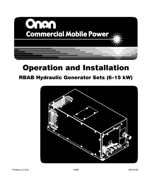
<strong>Operation</strong> <strong>and</strong> <strong>Installation</strong><br />
RBAB Hydraulic Generator Sets (6−15 kW)<br />
Printed in U.S.A. 10/06<br />
943-0103
Table of Contents<br />
SECTION<br />
PAGE<br />
SAFETY PRECAUTIONS . . . . . . . . . . . . . . . . . . . . . . . . . . . . . . . . . . . . . . . . . . . . . . . . . . . . . . . . . . . II<br />
SPECIFICATIONS . . . . . . . . . . . . . . . . . . . . . . . . . . . . . . . . . . . . . . . . . . . . . . . . . . . . . . . . . . . . . . . . . . III<br />
INTRODUCTION . . . . . . . . . . . . . . . . . . . . . . . . . . . . . . . . . . . . . . . . . . . . . . . . . . . . . . . . . . . . . . . . . . . 1<br />
About this Manual . . . . . . . . . . . . . . . . . . . . . . . . . . . . . . . . . . . . . . . . . . . . . . . . . . . . . . . . . . . . 1<br />
How to Obtain Parts <strong>and</strong> Service . . . . . . . . . . . . . . . . . . . . . . . . . . . . . . . . . . . . . . . . . . . . . . . 1<br />
Product Description . . . . . . . . . . . . . . . . . . . . . . . . . . . . . . . . . . . . . . . . . . . . . . . . . . . . . . . . . . 1<br />
OPERATION . . . . . . . . . . . . . . . . . . . . . . . . . . . . . . . . . . . . . . . . . . . . . . . . . . . . . . . . . . . . . . . . . . . . . . . 2<br />
Starting <strong>and</strong> Stopping . . . . . . . . . . . . . . . . . . . . . . . . . . . . . . . . . . . . . . . . . . . . . . . . . . . . . . . . . 2<br />
Display Module . . . . . . . . . . . . . . . . . . . . . . . . . . . . . . . . . . . . . . . . . . . . . . . . . . . . . . . . . . . . . . 2<br />
MAINTENANCE . . . . . . . . . . . . . . . . . . . . . . . . . . . . . . . . . . . . . . . . . . . . . . . . . . . . . . . . . . . . . . . . . . . . 3<br />
Oil Level . . . . . . . . . . . . . . . . . . . . . . . . . . . . . . . . . . . . . . . . . . . . . . . . . . . . . . . . . . . . . . . . . . . . 3<br />
Oil Filter . . . . . . . . . . . . . . . . . . . . . . . . . . . . . . . . . . . . . . . . . . . . . . . . . . . . . . . . . . . . . . . . . . . . 3<br />
Breather Filter . . . . . . . . . . . . . . . . . . . . . . . . . . . . . . . . . . . . . . . . . . . . . . . . . . . . . . . . . . . . . . . 3<br />
Generator . . . . . . . . . . . . . . . . . . . . . . . . . . . . . . . . . . . . . . . . . . . . . . . . . . . . . . . . . . . . . . . . . . . 3<br />
INSTALLATION . . . . . . . . . . . . . . . . . . . . . . . . . . . . . . . . . . . . . . . . . . . . . . . . . . . . . . . . . . . . . . . . . . . . 4<br />
Genset . . . . . . . . . . . . . . . . . . . . . . . . . . . . . . . . . . . . . . . . . . . . . . . . . . . . . . . . . . . . . . . . . . . . . 4<br />
Oil Reservoir . . . . . . . . . . . . . . . . . . . . . . . . . . . . . . . . . . . . . . . . . . . . . . . . . . . . . . . . . . . . . . . . 5<br />
Genset Display Module . . . . . . . . . . . . . . . . . . . . . . . . . . . . . . . . . . . . . . . . . . . . . . . . . . . . . . . 5<br />
Genset On / Off Switch . . . . . . . . . . . . . . . . . . . . . . . . . . . . . . . . . . . . . . . . . . . . . . . . . . . . . . . 5<br />
Battery . . . . . . . . . . . . . . . . . . . . . . . . . . . . . . . . . . . . . . . . . . . . . . . . . . . . . . . . . . . . . . . . . . . . . 5<br />
Wiring Connections . . . . . . . . . . . . . . . . . . . . . . . . . . . . . . . . . . . . . . . . . . . . . . . . . . . . . . . . . . . 6<br />
Hydraulic Pump . . . . . . . . . . . . . . . . . . . . . . . . . . . . . . . . . . . . . . . . . . . . . . . . . . . . . . . . . . . . . . 7<br />
Hydraulic Connections . . . . . . . . . . . . . . . . . . . . . . . . . . . . . . . . . . . . . . . . . . . . . . . . . . . . . . . . 8<br />
Startup . . . . . . . . . . . . . . . . . . . . . . . . . . . . . . . . . . . . . . . . . . . . . . . . . . . . . . . . . . . . . . . . . . . . . 8<br />
TROUBLESHOOTING . . . . . . . . . . . . . . . . . . . . . . . . . . . . . . . . . . . . . . . . . . . . . . . . . . . . . . . . . . . . . . 10<br />
Noisy Pump or Motor . . . . . . . . . . . . . . . . . . . . . . . . . . . . . . . . . . . . . . . . . . . . . . . . . . . . . . . . . 10<br />
Noisy Generator . . . . . . . . . . . . . . . . . . . . . . . . . . . . . . . . . . . . . . . . . . . . . . . . . . . . . . . . . . . . . 10<br />
No Output or Air Discharge—Engine Running . . . . . . . . . . . . . . . . . . . . . . . . . . . . . . . . . . . . 11<br />
No Output—Genset Running <strong>and</strong> Air Discharging . . . . . . . . . . . . . . . . . . . . . . . . . . . . . . . 12<br />
Frequency Too High or Too Low or Unstable . . . . . . . . . . . . . . . . . . . . . . . . . . . . . . . . . . . . 12<br />
Voltage Too High or Too Low or Unstable . . . . . . . . . . . . . . . . . . . . . . . . . . . . . . . . . . . . . . . 13<br />
OUTLINE DRAWING (6KW, 8KW, 10KW)—SHEET 1 . . . . . . . . . . . . . . . . . . . . . . . . . . . . . . . . . . . . A-1<br />
OUTLINE DRAWING (6KW, 8KW, 10KW)—SHEET 2 . . . . . . . . . . . . . . . . . . . . . . . . . . . . . . . . . . . . A-2<br />
OUTLINE DRAWING (15 KW)—SHEET 1 . . . . . . . . . . . . . . . . . . . . . . . . . . . . . . . . . . . . . . . . . . . . . . A-3<br />
OUTLINE DRAWING (15 KW)—SHEET 2 . . . . . . . . . . . . . . . . . . . . . . . . . . . . . . . . . . . . . . . . . . . . . . A-4<br />
OUTLINE DRAWING (ALL MODELS) . . . . . . . . . . . . . . . . . . . . . . . . . . . . . . . . . . . . . . . . . . . . . . . . . . A-5<br />
WIRING SCHEMATIC . . . . . . . . . . . . . . . . . . . . . . . . . . . . . . . . . . . . . . . . . . . . . . . . . . . . . . . . . . . . . . . A-6<br />
i
Safety Precautions<br />
Thoroughly read <strong>Operation</strong> <strong>and</strong> <strong>Installation</strong> before<br />
operating the genset. Safe operation <strong>and</strong><br />
top performance can be only be attained when<br />
equipment is operated <strong>and</strong> maintained properly.<br />
The following symbols in this manual alert you to potential<br />
hazards to the operator, service person <strong>and</strong><br />
equipment.<br />
DANGER alerts you to an immediate hazard<br />
that will result in severe personal injury or<br />
death.<br />
WARNING alerts you to a hazard or unsafe<br />
practice that can result in severe personal injury<br />
or death.<br />
CAUTION alerts you to a hazard or unsafe<br />
practice that can result in personal injury or<br />
equipment damage.<br />
Electricity, moving parts, batteries <strong>and</strong> high-pressure<br />
hydraulic fluid present hazards that can result<br />
in severe personal injury or death.<br />
GENERAL PRECAUTIONS<br />
• Make sure all fasteners are secure <strong>and</strong> torqued<br />
properly.<br />
• Do not work on the genset when mentally or<br />
physically fatigued or after consuming alcohol<br />
or drugs.<br />
• You must be trained <strong>and</strong> experienced to make<br />
adjustments while the genset is running—hot,<br />
moving or electrically live parts can cause severe<br />
personal injury or death.<br />
• Keep multi-class ABC fire extinguishers h<strong>and</strong>y.<br />
Class A fires involve ordinary combustible materials<br />
such as wood <strong>and</strong> cloth; Class B fires,<br />
combustible <strong>and</strong> flammable liquid fuels <strong>and</strong><br />
gaseous fuels; Class C fires, live electrical<br />
equipment. (ref. NFPA No. 10)<br />
• Genset installation <strong>and</strong> operation must comply<br />
with all applicable local, state <strong>and</strong> federal codes<br />
<strong>and</strong> regulations.<br />
GENERATOR VOLTAGE IS DEADLY!<br />
• Generator electrical output connections must<br />
be made by a trained <strong>and</strong> experienced electrician<br />
in accordance with applicable codes.<br />
• Use caution when working on live electrical<br />
equipment. Remove jewelry, make sure clothing<br />
<strong>and</strong> shoes are dry, st<strong>and</strong> on a dry wooden<br />
platform or rubber insulating mat <strong>and</strong> use tools<br />
with insulated h<strong>and</strong>les.<br />
BATTERY GAS IS EXPLOSIVE<br />
• Wear safety glasses.<br />
• Do not smoke.<br />
• To reduce arcing when disconnecting or reconnecting<br />
battery cables, always disconnect the<br />
negative (−) battery cable first <strong>and</strong> reconnect it<br />
last.<br />
MOVING PARTS CAN CAUSE SEVERE<br />
PERSONAL INJURY OR DEATH<br />
• Do not wear loose clothing or jewelry near moving<br />
parts such as PTO shafts, fans, belts <strong>and</strong><br />
pulleys.<br />
• Keep h<strong>and</strong>s away from moving parts.<br />
• Keep guards in place over fans, belts, pulleys,<br />
<strong>and</strong> other moving parts.<br />
HYDRAULIC FLUID UNDER PRESSURE<br />
CAN CAUSE SEVERE PERSONAL INJURY<br />
• Always shut down the engine that drives the hydraulic<br />
pump before loosening or tightening fittings.<br />
• The high pressure spray from a leak or fitting in<br />
a hydraulic line can penetrate the skin, leading<br />
to possible blood poisoning. Wear safety<br />
glasses. Do not delay getting proper medical<br />
attention if exposed to high pressure oil spray.<br />
hydraulic-1<br />
ii
Specifications<br />
6 kW Models 1 8 kW Models 1<br />
GENERATOR: 2-Pole Revolving Field, 1-Bearing, Self-Excited, 1-Phase, Electronic Voltage <strong>and</strong> Frequency Regulation<br />
Frequency 60 Hertz 60 Hertz 50 Hertz<br />
Voltage (3-Wire) 120 / 240 volts 120 / 240 volts 120 / 240 volts<br />
Current 50 / 25 amps 66 / 33 amps 66 / 33 amps<br />
Speed 3600 rpm 3600 rpm 3600 rpm<br />
DC SYSTEM:<br />
Battery Voltage 12 volts 12 volts 12 volts<br />
Control Fuse (F1) 20 amp blade-type 20 amp blade-type 20 amp blade-type<br />
Control Fuse (F2) 0.125 amp slow-blow 0.125 amp slow-blow 0.125 amp slow-blow<br />
INSTALLATION: Hydraulic Pump<br />
Min − Max Pump Speed 850 to 3000 rpm 850 to 3000 rpm 850 to 3000 rpm<br />
SAE Flange B B B<br />
SAE Spline Shaft B—13 Tooth or BB—15 Tooth B—13 Tooth or BB—15 Tooth B—13 Tooth or BB—15 Tooth<br />
SAE Straight Key Shaft B—1 inch B—1 inch B—1 inch<br />
Flow 14 gpm 14 gpm 14 gpm<br />
Maximum Pressure 4000 psi 4000 psi 4000 psi<br />
Hydraulic Fluid<br />
Dextron III or Anti-Wear<br />
Hydraulic Fluid<br />
Dextron III or Anti-Wear<br />
Hydraulic Fluid<br />
Dextron III or Anti-Wear<br />
Hydraulic Fluid<br />
Weight 55 lb (25 Kg) 55 lb (25 Kg) 55 lb (25 Kg)<br />
Max Engine Draw 23.3 hp 26.0 hp 23.0 hp<br />
INSTALLATION: Hydraulic Hose & Fittings<br />
Pump to<br />
Motor<br />
Genset to<br />
Oil Reservoir<br />
Pump Case to<br />
Oil Reservoir<br />
Oil Reservoir to Pump<br />
INSTALLATION: Generator Module<br />
#10, 4000 psi Hose;<br />
37° Fittings<br />
#12, 200 psi Hose;<br />
37° Fittings<br />
#10, 200 psi Hose;<br />
37° Fittings<br />
#20, 200 psi Hose;<br />
37° Fittings<br />
#10, 4000 psi Hose;<br />
37° Fittings<br />
#12, 200 psi Hose;<br />
37° Fittings<br />
#10, 200 psi Hose;<br />
37° Fittings<br />
#20, 200 psi Hose;<br />
37° Fittings<br />
#10, 4000 psi Hose;<br />
37° Fittings<br />
#12, 200 psi Hose;<br />
37° Fittings<br />
#10, 200 psi Hose;<br />
37° Fittings<br />
#20, 200 psi Hose;<br />
37° Fittings<br />
Noise 72 dB(A)2 72 dB(A)2 72 dB(A)2<br />
Weight 179 lb (81 Kg) 179 lb (81 Kg) 179 lb (81 Kg)<br />
Dimensions (L x W x H)<br />
31.98 x 15.79 x 13.72 in<br />
(812.4 x 401.1 x 348.4 mm)<br />
31.98 x 15.79 x 13.72 in<br />
(812.4 x 401.1 x 348.4 mm)<br />
31.98 x 15.79 x 13.72 in<br />
(812.4 x 401.1 x 348.4 mm)<br />
Cooling Air Flow 1450 cfm 1450 cfm 1450 cfm<br />
Max Ambient Temp<br />
Continuous Full Load<br />
Intermittent Load<br />
120° F (49° C)<br />
140° F (60° C)<br />
1 − Rated @ 1.0 PF<br />
2 − Rated @ 10 ft (3 m), before installation, under full load.<br />
120° F (49° C)<br />
140° F (60° C)<br />
120° F (49° C)<br />
140° F (60° C)<br />
iii
10 kW Models 1 15 kW Models 1<br />
GENERATOR: 2-Pole Revolving Field, 1-Bearing, Self-Excited, 1-Phase, Electronic Voltage <strong>and</strong> Frequency Regulation<br />
Frequency 60 Hertz 60 Hertz<br />
Voltage (3-Wire) 120 / 240 volts 120 / 240 volts<br />
Current 83 / 42 amps 125 / 62.5 amps<br />
Speed 3600 rpm 3600 rpm<br />
DC SYSTEM:<br />
Battery Voltage 12 volts 12 volts<br />
Control Fuse (F1) 20 amp blade-type 20 amp blade-type<br />
Control Fuse (F2 ) 0.125 amp slow-blow 0.125 amp slow-blow<br />
INSTALLATION: Hydraulic Pump<br />
Min − Max Pump Speed 850 to 3000 rpm 1000 to 3000 rpm<br />
SAE Flange B B<br />
SAE Spline Shaft B—13 Tooth or BB—15 Tooth BB—15 Tooth<br />
SAE Straight Key Shaft B—1 inch B—1 inch<br />
Flow 14 gpm 16.1 gpm<br />
Maximum Pressure 4000 psi 4000 psi<br />
Hydraulic Fluid Dextron III or Anti-Wear Hydraulic Fluid Dextron III or Anti-Wear Hydraulic Fluid<br />
Weight 55 lb (25 Kg) 55 lb (25 Kg)<br />
Max Engine Draw 28.7 hp 40.0 hp<br />
INSTALLATION: Hydraulic Hose & Fittings<br />
Pump to<br />
Motor<br />
Genset to<br />
Oil Reservoir<br />
Pump Case to<br />
Oil Reservoir<br />
Oil Reservoir to Pump<br />
INSTALLATION: Generator Module<br />
#10, 4000 psi Hose;<br />
37° Fittings<br />
#12, 200 psi Hose;<br />
37° Fittings<br />
#10, 200 psi Hose;<br />
37° Fittings<br />
#20, 200 psi Hose;<br />
37° Fittings<br />
#10, 4000 psi Hose;<br />
37° Fittings<br />
#12, 200 psi Hose;<br />
37° Fittings<br />
#10, 200 psi Hose;<br />
37° Fittings<br />
#20, 200 psi Hose;<br />
37° Fittings<br />
Noise 72 dB(A)2 72 dB(A)2<br />
Weight 179 lb (81 Kg) 225 lb (102 Kg)<br />
Dimensions (L x W x H)<br />
31.98 x 15.79 x 13.72 in<br />
(812.4 x 401.1 x 348.4 mm)<br />
39.17 x 15.81 x 13.7 in<br />
(995 x 401.5 x 348 mm)<br />
Cooling Air Flow 1450 cfm 1600 cfm<br />
Max Ambient Temp<br />
Continuous Full Load<br />
Intermittent Load<br />
120° F (49° C)<br />
140° F (60° C)<br />
1 − Rated @ 1.0 PF<br />
2 − Rated @ 10 ft (3 m), before installation, under full load.<br />
120° F (49° C)<br />
140° F (60° C)<br />
iv
Introduction<br />
ABOUT THIS MANUAL<br />
This manual covers <strong>Operation</strong> <strong>and</strong> <strong>Installation</strong> of<br />
the hydraulic generator sets (gensets) listed on the<br />
front cover. It includes Specifications, Maintenance<br />
<strong>and</strong> Troubleshooting. For more information on the<br />
genset, refer to Parts Catalog 943-0204 <strong>and</strong> Service<br />
Manual 943-0503.<br />
HOW TO OBTAIN PARTS AND SERVICE<br />
To obtain parts or service contact the nearest <strong>Cummins</strong>®/<strong>Onan</strong>®<br />
dealer or distributor.<br />
• In the United States or Canada, call<br />
1-800-888-6626 <strong>and</strong> select Option 1 (touchtone<br />
phones only) or fax 1-763-528-7229<br />
(<strong>Cummins</strong> Power Generation).<br />
• Outside North America, call 1-763-574-5000<br />
(<strong>Cummins</strong> Power Generation) between<br />
7:30 AM <strong>and</strong> 4:00 PM Central St<strong>and</strong>ard Time,<br />
Monday through Friday or fax 1-763-574-8087.<br />
• When ordering parts or calling for service, be<br />
ready to provide the complete model number<br />
<strong>and</strong> serial number, both of which are printed on<br />
the genset nameplate.<br />
PRODUCT DESCRIPTION<br />
The genset consists of several components or modules<br />
that are installed at various locations on the vehicle.<br />
The components are interconnected electrically<br />
<strong>and</strong> hydraulically as shown on the appropriate<br />
Outline Drawing (beginning on Page A-1).<br />
• Genset − The genset is an AC generator driven<br />
by an hydraulic motor. An automatic voltage<br />
regulator maintains nominal AC output voltage<br />
under varying generator loads. An oil-to-air<br />
heat exchanger in the generator box cools the<br />
oil (hydraulic fluid) before it is returned to the<br />
reservoir.<br />
• Hydraulic Pump − The hydraulic pump is driven<br />
by a power takeoff on the vehicle transmission<br />
to power the generator motor. The pump<br />
controller (located in the genset) senses AC<br />
output frequency <strong>and</strong> adjusts pump piston<br />
stroke as engine speed varies in response to<br />
other concurrent tasks, such as vehicle propulsion<br />
or pumping, to maintain constant flow <strong>and</strong><br />
thus nominal generator frequency (50 or 60<br />
Hz).<br />
• Oil Reservoir − The oil reservoir has a three<br />
gallon oil capacity. It is equipped with a full-flow<br />
6 micron oil filter, oil level sight glass, filter pressure<br />
gauge, breather filter <strong>and</strong> oil fill cap.<br />
• Generator Display Module − The generator<br />
display module displays generator output voltage,<br />
frequency <strong>and</strong> current. It also displays the<br />
temperature of the oil returning to the oil reservoir<br />
<strong>and</strong> the number of hours run.<br />
• Generator ON / OFF Switch − The vehicle<br />
builder provides the generator ON / OFF<br />
switch.<br />
• Hydraulic Fluid − The genset is designed for<br />
use with Dextron III or Anti-Wear Hydraulic<br />
Fluid (oil).<br />
<strong>Cummins</strong> <strong>and</strong> <strong>Onan</strong> are registered trademarks of <strong>Cummins</strong> Inc.<br />
1
<strong>Operation</strong><br />
STARTING AND STOPPING<br />
Genset operation involves switching the genset ON<br />
or OFF <strong>and</strong> monitoring the genset display module<br />
(Figure 1) <strong>and</strong> oil level sight glass (Figure 2).<br />
Starting<br />
Start the vehicle engine <strong>and</strong> engage the PTO clutch<br />
(if so equipped). Switch the genset ON <strong>and</strong> then<br />
connect or turn on the loads.<br />
Note: It takes 4 to 8 seconds for the genset to reach<br />
rated frequency each time it is started.<br />
AC Output<br />
DISPLAY MODULE<br />
The display module continuously displays the AC<br />
output frequency <strong>and</strong> voltage <strong>and</strong> current (amps) in<br />
each leg. See Figure 1.<br />
Hour Meter<br />
Press the MODE button once to display the number<br />
of hours run. The display will revert to AC output.<br />
Oil Temperature<br />
Press the MODE button twice to display the temperature<br />
of the oil returning to the oil reservoir. The display<br />
will revert to AC output.<br />
CAUTION Although the genset is capable of<br />
starting up with all loads connected, generally,<br />
to save wear <strong>and</strong> tear, it is recommended that<br />
the genset be turned ON first before connecting<br />
loads.<br />
Stopping<br />
First disconnect all loads <strong>and</strong> then switch the genset<br />
OFF. The PTO need not be disengaged when<br />
switching the genset OFF because pump piston<br />
stroke goes to zero.<br />
CAUTION Leaving the generator switch ON<br />
while the vehicle is st<strong>and</strong>ing by with the engine<br />
off can run down the engine starting battery <strong>and</strong><br />
cause damage to genset components. Always<br />
switch OFF the generator before parking the vehicle<br />
in st<strong>and</strong>by.<br />
FIGURE 1. DISPLAY MODULE<br />
2
Maintenance<br />
OIL LEVEL<br />
CAUTION The slightest amount of dirt in a hydraulic<br />
system can damage precisely machined<br />
internal components or cause the regulator<br />
spool valve to stick, resulting in erratic operation.<br />
Keep dirt out:<br />
Thoroughly clean the outside of a fitting or<br />
cap before disconnecting or removing it.<br />
Cap all openings in components <strong>and</strong> hoses<br />
with proper JIC caps when disassembling.<br />
Before connecting, thoroughly flush each<br />
hose <strong>and</strong> blow sponge pigs through until<br />
they come out clean.<br />
Regularly replace the oil filter.<br />
Never reuse drained hydraulic fluid.<br />
Check oil level often <strong>and</strong> keep it within 1/4 inch of the<br />
top of the sight glass (Figure 2). Only use Dextron III<br />
or Anti-Wear Hydraulic Fluid. Pump the oil through a<br />
10 micron filter (SAE Class 4) when filling the reservoir.<br />
OIL FILTER<br />
Replace the oil filter every 1000 hours of operation<br />
or sooner if the needle on the filter pressure gauge<br />
approaches the red area (25 psi).<br />
BREATHER FILTER<br />
Replace the breather filter on the oil reservoir every<br />
1000 hours of operation.<br />
GENERATOR<br />
Have the generator bearing <strong>and</strong> generator brushes<br />
<strong>and</strong> slip rings checked every 2000 hours of operation,<br />
or 5 years, whichever comes first. This must be<br />
performed by a trained <strong>and</strong> experienced mechanic<br />
(authorized <strong>Onan</strong> dealer).<br />
BREATHER<br />
FILTER<br />
FILTER<br />
ELEMENT CAP<br />
OIL FILL CAP<br />
OIL LEVEL<br />
SIGHT GLASS<br />
RETURN<br />
OIL<br />
FILTER PRESSURE<br />
GAUGE<br />
PUMP CASE<br />
RETURN OIL<br />
TO PUMP<br />
(SUCTION)<br />
FIGURE 2. OIL RESERVOIR<br />
3
<strong>Installation</strong><br />
GENSET<br />
WARNING Improper installation can result in<br />
severe personnel injury or death. The installer<br />
must be trained <strong>and</strong> experienced in the installation<br />
of electrical, mechanical <strong>and</strong> hydraulic<br />
equipment.<br />
Note: Manuals are updated from time-to-time to reflect<br />
changes in the equipment <strong>and</strong> its specifications.<br />
For this reason, only the copy of the installation<br />
manual supplied with the genset should be used<br />
as a guide for the installation.<br />
The builder of the vehicle bears sole responsibility<br />
for the selection of the appropriate genset, for its<br />
proper installation <strong>and</strong> for obtaining approvals from<br />
the authorities (if any) having jurisdiction over the<br />
installation. The genset is suitable for <strong>Installation</strong> in<br />
accordance with the National Electrical Code<br />
(NFPA No. 70) or the Canadian Electrical Code<br />
(C22.1). When properly installed it will meet the certification<br />
requirements of NFPA 1903.<br />
Before mounting the genset, pump or oil reservoir,<br />
carefully consider the routing of all hydraulic hoses<br />
<strong>and</strong> wiring.<br />
Refer to the Outline Drawings (beginning on<br />
Page A-1) regarding outside dimensions, weight,<br />
mounting bolt holes, cooling air inlet <strong>and</strong> outlet<br />
openings <strong>and</strong> hydraulic <strong>and</strong> wiring connections.<br />
Cooling Air Flow<br />
For sufficient air flow to cool the genset, provide at<br />
least 3 inches (76 mm) of clearance in front of <strong>and</strong><br />
across the entire face of the finned heat exchanger<br />
(air outlet) <strong>and</strong> in front of both air inlets. Two (2) air<br />
inlets must be open. Rearrange the plates <strong>and</strong><br />
screens, as necessary, between the four or five air<br />
inlet openings. The location with respect to bulkheads<br />
<strong>and</strong> other equipment must be such that the<br />
warm air does not recirculate back into the genset<br />
air inlets.<br />
Cooling Air Test<br />
To determine whether the installation allows for sufficient<br />
genset cooling, monitor oil temperature with<br />
the display module (Figure 1) while running the genset<br />
under full load for at least two hours. Oil temperature<br />
must not exceed 185° F (85° C). If it does,<br />
check inlet air temperature.<br />
• Inlet air temperature should not exceed ambient<br />
air temperature by more than 25° F (14° C).<br />
If it does, cooling air is recirculating between<br />
the outlet <strong>and</strong> inlets or is being heated some<br />
other way, such as by passing through the hot<br />
engine compartment. The genset must be relocated<br />
or the air inlets <strong>and</strong> outlets baffled to prevent<br />
recirculation or the entrance of hot air from<br />
another source.<br />
• If inlet air temperature exceeds ambient air<br />
temperature by less than 25° F (14° C) but oil<br />
temperature exceeds 185° F (85° C), inlet or<br />
outlet air is being blocked or restricted. The<br />
genset must be relocated or the obstructions<br />
removed.<br />
• If inlet air temperatures exceed 120° F (49° C)<br />
the genset must be derated to prevent oil temperatures<br />
from exceeding 185° F (85° C).<br />
NFPA Certification Test<br />
As oil temperature rises, hydraulic efficiency falls off<br />
slightly. Therefore, load the genset to 103-104 percent<br />
of rated load at the start of the 2-hour NFPA<br />
Certification Test. If the inlet air temperature does<br />
not exceed 120° F (49° C), the genset will finish the<br />
test carrying at least 100 percent of rated load,<br />
meeting the certification requirements. See Cooling<br />
Air Test if air temperature exceeds specifications.<br />
Hydraulic <strong>and</strong> Electric Interconnections<br />
See HYDRAULIC CONNECTIONS (Page 8) <strong>and</strong><br />
WIRING CONNECTIONS (Page 6) for important<br />
considerations with respect to interconnections between<br />
components in the system.<br />
4
OIL RESERVOIR<br />
When locating <strong>and</strong> mounting the oil reservoir, consider<br />
the following:<br />
1. The bottom of the oil reservoir must be at least<br />
2 feet (610 mm) higher than the top of the<br />
pump. It is recommended that the oil reservoir<br />
be the highest point in the hydraulic system.<br />
2. The fill cap <strong>and</strong> filter must be readily accessible<br />
for filling oil <strong>and</strong> changing filters (Page 3).<br />
There must be at least 8 inches (204 mm) of<br />
clearance for withdrawing the filter element.<br />
3. The oil level sight glass <strong>and</strong> filter pressure<br />
gauge must be readily visible. The genset display<br />
module <strong>and</strong> ON/OFF switch should be in<br />
view from the location of the oil reservoir.<br />
4. See HYDRAULIC CONNECTIONS (Page 8)<br />
regarding hose connections.<br />
GENSET DISPLAY MODULE<br />
Locate the genset display module at a convenient<br />
location. The ON/OFF switch <strong>and</strong> oil reservoir<br />
gauges should be in view from the location of the<br />
display module. Mount the display module with four<br />
(4) 1/8 inch screws. Interconnect it with the other<br />
system components with lead harness<br />
Nos. 338-4087, 338-4088 <strong>and</strong> 338-4089.<br />
GENSET ON / OFF SWITCH<br />
Provide an ON/OFF switch rated at least 20 amps at<br />
12 VDC to switch the genset ON <strong>and</strong> OFF (see<br />
schematic, Page A-6). Locate the switch at a convenient<br />
location. The genset display module <strong>and</strong> oil<br />
reservoir gauges should be in view from the location<br />
of the switch. Interconnect the ON/OFF switch <strong>and</strong><br />
genset with lead harness No. 338-4084.<br />
BATTERY<br />
Genset control <strong>and</strong> monitoring requires connection<br />
to a 12 volt battery. Use lead harness No. 338-4085<br />
to connect the genset to a terminal block in a vehicle<br />
equipment cabinet that provides battery positive (+)<br />
<strong>and</strong> negative (−) terminals.<br />
Lead harness No. 338-4085 has a 20 amp bladetype<br />
fuse holder <strong>and</strong> fuse (yellow) to protect the<br />
genset control circuits from shorts to ground.<br />
5
WIRING CONNECTIONS<br />
See the appropriate Outline Drawing (beginning on<br />
Page A-1) for wiring connections between the components<br />
of the system. Also refer to the wiring schematic<br />
on Page A-6.<br />
AC Output Connections<br />
AC power output is through four Type CCXL conductors<br />
12 ft (3.6 m) long in rain-tight flexible conduit.<br />
Conductors <strong>and</strong> conduit are sized according to<br />
Table 1. Refer to the wiring schematic on Page A-6.<br />
TABLE 1. WIRING GAUGE AND CONDUIT SIZE<br />
KW Wire Gauge Conduit Size<br />
6 & 8 12 AWG 1/2 inch<br />
10 10 AWG 3/4 inch<br />
15 8 AWG 1-1/4 inch<br />
Control <strong>and</strong> Monitoring Connections<br />
All wiring interconnections between components of<br />
the system are done with 15 foot (4.3 m) long harnesses<br />
with sealed connectors (Table 2) that match<br />
the connectors on the component leads.<br />
TABLE 2. WIRING HARNESSES<br />
HARNESS<br />
CONNECTIONS<br />
338-4084 Genset to Remote ON/OFF Switch<br />
338-4085 Genset to Battery<br />
338-4086 Genset to Pump Actuator<br />
338-4087 For Display Power (from Genset)<br />
338-4088 For Oil Temperature Display from Sensor<br />
338-4089 For AC Display from Genset<br />
Wiring Methods<br />
Follow the National Electrical Code (USA) or Canadian<br />
Electrical Code, as required. Especially note<br />
the following:<br />
1. Have a trained <strong>and</strong> experienced electrician supervise<br />
<strong>and</strong> inspect the installation of all AC wiring.<br />
2. Provide overcurrent protection as required at<br />
the vehicle AC distribution panel. See Article<br />
445, NFPA No. 70 (USA) or Part 1, Section 14<br />
of C22.1 (Canada).<br />
3. Install vibration-proof switches <strong>and</strong> controls<br />
that won’t open <strong>and</strong> close circuits when the vehicle<br />
is in motion.<br />
4. Provide ground fault circuit interrupters<br />
(GFCIs) for all convenience power receptacles.<br />
5. Route AC power wiring <strong>and</strong> remote control wiring<br />
separately.<br />
6. Seal all conduit openings into the vehicle interior<br />
to keep out vehicle engine exhaust. Apply silicone<br />
rubber or equivalent sealant inside <strong>and</strong><br />
outside each conduit connector. (Flexible conduit<br />
is not vapor-tight <strong>and</strong> will allow exhaust gas<br />
to enter along the wires if not sealed.)<br />
WARNING EXHAUST GAS IS DEADLY!<br />
Seal all wiring openings into the vehicle interior<br />
to keep out exhaust gas.<br />
7. Bond the genset <strong>and</strong> all connected AC <strong>and</strong> DC<br />
equipment <strong>and</strong> controls to a common grounding<br />
point in accordance with applicable codes.<br />
WARNING Faulty grounding can lead to<br />
fire or electrocution, resulting in severe personal<br />
injury or death. Grounding must be in<br />
accordance with applicable codes.<br />
6
HYDRAULIC PUMP<br />
Interconnect the pump actuator <strong>and</strong> genset with<br />
lead harness No. 338-4086.<br />
Refer to Specifications regarding minimum <strong>and</strong><br />
maximum pump speeds, SAE mounting flanges,<br />
drives <strong>and</strong> hose connections. Pumps are available<br />
for clockwise or counterclockwise rotation, as determined<br />
by looking at the drive shaft end.<br />
Note: When selecting a PTO, make sure it will turn the<br />
pump in the right direction within the speed range<br />
specified.<br />
When locating <strong>and</strong> mounting the pump (Figure 3)<br />
consider possible interference with frame rails, cab<br />
floor, exhaust pipes <strong>and</strong> other vehicle components.<br />
The pump must be mounted such that one of the<br />
three case drain ports points up.<br />
Mount the pump on a frame cross member <strong>and</strong> connect<br />
it to the PTO by means of a drive shaft, observing<br />
the following:<br />
1. The drive shaft can turn at a very high rpm. To<br />
minimize vibration <strong>and</strong> wear, locate the pump<br />
such that the drive shaft U-joint angles will be<br />
as small as possible. The PTO <strong>and</strong> pump must<br />
be parallel within 1 degree <strong>and</strong> offset at a shaft<br />
angle of 5 degrees or less. Use st<strong>and</strong>ard practice<br />
in designing, fabricating <strong>and</strong> assembling<br />
the pump bracket <strong>and</strong> drive shaft.<br />
2. On models that have splined drive shafts,<br />
grease the splines with the tube of grease provided.<br />
3. Use lock wires to secure hub set screws.<br />
4. Provide guards around drive shafts at locations<br />
where they could accidentally be touched.<br />
WARNING Rotating drive shafts can cause<br />
severe personal injury or death. Guards<br />
must be provided to prevent accidental<br />
contact.<br />
CASE DRAIN FITTING<br />
IN TOP PORT<br />
GREASE SPLINES<br />
PUMP<br />
ACTUATOR<br />
CONNECTOR<br />
PUMP<br />
SUCTION<br />
HOSE<br />
USE AN ALTERNATE CASE<br />
DRAIN PORT WHEN ON TOP<br />
PUMP<br />
OUTPUT<br />
HOSE<br />
FIGURE 3. PUMP ASSEMBLY<br />
7
HYDRAULIC CONNECTIONS<br />
CAUTION The slightest amount of dirt in an<br />
hydraulic system can damage precisely machined<br />
internal components or cause the regulator<br />
spool valve to stick, resulting in erratic operation.<br />
Keep dirt out:<br />
Thoroughly clean the outside of a fitting or<br />
cap before disconnecting or removing it.<br />
Cap all openings in components <strong>and</strong> hoses<br />
with proper JIC caps when disassembling.<br />
Before connecting, thoroughly flush each<br />
hose <strong>and</strong> blow sponge pigs through until<br />
they come out clean.<br />
Regularly replace the oil filter.<br />
Never reuse drained hydraulic fluid.<br />
See the appropriate Outline Drawing (beginning on<br />
Page A-1) for the hydraulic interconnections between<br />
the components of the system. Specially note<br />
the following:<br />
1. Consider that hoses shrink slightly in length<br />
<strong>and</strong> exp<strong>and</strong> slightly in diameter under pressure.<br />
2. To avoid trapping air, hoses should slope up<br />
from the pump. The hose between the genset<br />
<strong>and</strong> oil reservoir should slope up to the reservoir.<br />
3. Do not bend hoses tighter than the hose<br />
manufacturer recommends.<br />
4. Flush hoses <strong>and</strong> cap them with JIC caps after<br />
cutting <strong>and</strong> terminating their ends.<br />
5. Use wide-sweep 90-degree fittings.<br />
6. Always use two wrenches when tightening fittings.<br />
7. Support, restrain <strong>and</strong> protect hydraulic hose as<br />
necessary to prevent chaffing.<br />
8. Do not apply engine power to the pump before<br />
filling the pump <strong>and</strong> system with oil as<br />
instructed under STARTUP.<br />
STARTUP<br />
Filling Hydraulic System<br />
1. Complete all hydraulic <strong>and</strong> electric connections<br />
<strong>and</strong> secure drive shaft guards.<br />
WARNING Rotating drive shafts can cause<br />
severe personal injury or death. Guards<br />
must be provided to prevent accidental<br />
contact.<br />
2. Turn the genset switch OFF.<br />
3. Disconnect all electrical loads.<br />
4. Disconnect the case drain hose <strong>and</strong> fill the<br />
pump case (top case drain port). Use a 10 micron<br />
filter (SAE Class 4) to filter the oil.<br />
5. Fill the oil reservoir to within 1/4 inch of the top<br />
of the sight glass (Page 3). Use a 10 micron<br />
filter (SAE Class 4) to filter the oil. The level will<br />
drop as the system fills. If possible, wait 1/2<br />
hour for air to escape from the system <strong>and</strong> then<br />
refill the reservoir.<br />
WARNING The high pressure spray from a<br />
leak or fitting in a hydraulic line can penetrate<br />
the skin, leading to possible blood poisoning<br />
— Wear safety glasses — Shut down<br />
the engine that drives the hydraulic pump<br />
before loosening or tightening fittings — Do<br />
not delay getting proper medical attention if<br />
exposed to high pressure oil spray.<br />
6. If possible, disable engine starting <strong>and</strong> crank<br />
the engine to fill the system with oil. Otherwise,<br />
start <strong>and</strong> run the engine for not more than 3 to<br />
5 seconds at a time. If a PTO clutch is provided,<br />
leave the engine running <strong>and</strong> engage the clutch<br />
for not more than 3 to 5 seconds at a time.<br />
CAUTION Running the pump without oil<br />
will quickly destroy the pump.<br />
7. Refill the reservoir if the level drops (Step 5).<br />
8. Repeat Steps 6 <strong>and</strong> 7 until the oil level stops<br />
dropping in the reservoir.<br />
9. When the system is full, turn the genset switch<br />
ON, let the engine run <strong>and</strong> listen for pump noise<br />
(metallic sound). Stop the engine or disengage<br />
the PTO clutch immediately if the pump is<br />
noisy. Repeat Steps Steps 6 <strong>and</strong> 7.<br />
8
Testing <strong>Operation</strong><br />
After the system has been filled, run the engine, turn<br />
ON the genset switch <strong>and</strong> check voltage, frequency<br />
<strong>and</strong> current (Page 2) under various loads <strong>and</strong> engine<br />
speeds.<br />
These gensets do not require a final speed adjustment.<br />
If the genset does not come up to rated frequency<br />
check for proper minimum pump speed.<br />
Call an authorized <strong>Onan</strong> dealer if stable voltage <strong>and</strong><br />
frequency or rated current cannot be attained.<br />
9
Troubleshooting<br />
This section covers problems that may be encountered<br />
<strong>and</strong> suggests possible causes <strong>and</strong> corrective<br />
actions. If you are unable to resolve the problem after<br />
taking the corrective actions suggested, call an<br />
authorized <strong>Onan</strong> dealer. See HOW TO OBTAIN<br />
PARTS AND SERVICE.<br />
NOISY PUMP OR MOTOR<br />
WARNING There are hazards present in troubleshooting that can cause equipment damage,<br />
severe personal injury or death. Troubleshooting must be performed by trained <strong>and</strong> experienced<br />
persons who know about the hazards of electricity, hydraulic systems <strong>and</strong> machinery. Read Safety<br />
Precautions inside the front cover <strong>and</strong> observe all instructions <strong>and</strong> precautions in this manual.<br />
Possible Cause<br />
Corrective Action<br />
1. Air trapped in hydraulic fluid Purge the air <strong>and</strong> refill the oil reservoir as necessary (Page 3).<br />
CAUTION<br />
the pump.<br />
Running the pump without oil will quickly destroy<br />
NOISY GENERATOR<br />
WARNING There are hazards present in troubleshooting that can cause equipment damage,<br />
severe personal injury or death. Troubleshooting must be performed by trained <strong>and</strong> experienced<br />
persons who know about the hazards of electricity, hydraulic systems <strong>and</strong> machinery. Read Safety<br />
Precautions inside the front cover <strong>and</strong> observe all instructions <strong>and</strong> precautions in this manual.<br />
Possible Cause<br />
1. Loose fan, worn bearing or<br />
misaligned rotor <strong>and</strong> motor<br />
Corrective Action<br />
See an authorized <strong>Onan</strong> dealer.<br />
10
NO OUTPUT OR AIR DISCHARGE—ENGINE RUNNING<br />
WARNING There are hazards present in troubleshooting that can cause equipment damage,<br />
severe personal injury or death. Troubleshooting must be performed by trained <strong>and</strong> experienced<br />
persons who know about the hazards of electricity, hydraulic systems <strong>and</strong> machinery. Read Safety<br />
Precautions inside the front cover <strong>and</strong> observe all instructions <strong>and</strong> precautions in this manual.<br />
Possible Cause<br />
Corrective Action<br />
1. ON/OFF Switch OFF Turn the switch ON.<br />
2. ON/OFF Switch was ON<br />
when the engine was started<br />
or the PTO was engaged<br />
Turn the switch OFF <strong>and</strong> then ON.<br />
3. Disengaged PTO Engage the PTO.<br />
4. Blown Fuse (F1) Replace with a 20 amp (yellow) blade-type fuse (Page A-6). If the<br />
new fuse blows, check for ground faults in harnesses 338-4084,<br />
338-4085 <strong>and</strong> 338-4087 <strong>and</strong> replace as necessary.<br />
5. Blown Fuse (F2) Replace with a 0.125 amp slow-blow fuse.<br />
6. Hydraulic fluid leak Check for <strong>and</strong> repair any leaks in the system <strong>and</strong> refill as necessary<br />
(Page 3).<br />
7. 12 VDC not available or polarity<br />
reversed.<br />
Disconnect connector J1 at the genset <strong>and</strong> check for 12 VDC<br />
across pins A <strong>and</strong> B <strong>and</strong> Positive (+) 12 VDC at pin A. See<br />
Page A-6. Service or reconnect as necessary.<br />
8. Faulty ON/OFF Switch Disconnect connector P2 at the genset <strong>and</strong> check for electrical<br />
continuity across pins A <strong>and</strong> B when the switch is turned on. See<br />
Page A-6. Replace a faulty switch.<br />
9. Faulty Lead Harness Check for bent, corroded or missing connector pins <strong>and</strong> damaged<br />
leads in harnesses 338-4084, 338-4085 <strong>and</strong> 338-4086 <strong>and</strong> replace<br />
as necessary.<br />
11
NO OUTPUT—GENSET RUNNING AND AIR DISCHARGING<br />
WARNING There are hazards present in troubleshooting that can cause equipment damage,<br />
severe personal injury or death. Troubleshooting must be performed by trained <strong>and</strong> experienced<br />
persons who know about the hazards of electricity, hydraulic systems <strong>and</strong> machinery. Read Safety<br />
Precautions inside the front cover <strong>and</strong> observe all instructions <strong>and</strong> precautions in this manual.<br />
Possible Cause<br />
1. Line circuit breaker (vehicle<br />
AC distribution panel) OFF,<br />
TRIPPED or faulty<br />
2. Misconnected Genset Power<br />
Supply Conductors<br />
Corrective Action<br />
a. If the circuit breaker is OFF, find out why, make sure it is safe to reconnect<br />
power, <strong>and</strong> then switch it ON.<br />
b. If the circuit breaker TRIPPED, shut down the genset <strong>and</strong> repair the<br />
shorted or grounded equipment that caused tripping.<br />
c. Replace a faulty circuit breaker.<br />
Reconnect the genset power supply conductors correctly at the vehicle<br />
AC distribution panel (Page A-6).<br />
FREQUENCY TOO HIGH OR TOO LOW OR UNSTABLE<br />
WARNING There are hazards present in troubleshooting that can cause equipment damage,<br />
severe personal injury or death. Troubleshooting must be performed by trained <strong>and</strong> experienced<br />
persons who know about the hazards of electricity, hydraulic systems <strong>and</strong> machinery. Read Safety<br />
Precautions inside the front cover <strong>and</strong> observe all instructions <strong>and</strong> precautions in this manual.<br />
Possible Cause<br />
3. Wrong PTO speed ratio or<br />
faulty hydraulic motor or controller<br />
Corrective Action<br />
a. Verify that the combination of PTO speed ratio <strong>and</strong> engine speed<br />
range results in pump speeds that fall within the specified range<br />
See Specifications. If pump speed falls outside the range, reinstall<br />
the PTO with a gear ratio that will keep pump speed within the specified<br />
range at all engine speeds.<br />
b. See an authorized <strong>Onan</strong> dealer.<br />
12
VOLTAGE TOO HIGH OR TOO LOW OR UNSTABLE<br />
WARNING There are hazards present in troubleshooting that can cause equipment damage,<br />
severe personal injury or death. Troubleshooting must be performed by trained <strong>and</strong> experienced<br />
persons who know about the hazards of electricity, hydraulic systems <strong>and</strong> machinery. Read Safety<br />
Precautions inside the front cover <strong>and</strong> observe all instructions <strong>and</strong> precautions in this manual.<br />
Possible Cause<br />
1. Wrong PTO speed ratio or<br />
faulty hydraulic motor or controller<br />
Corrective Action<br />
a. Voltage is frequency dependent. Verify that the combination of<br />
PTO speed ratio <strong>and</strong> engine speed range results in pump speeds<br />
that fall within the specified range. see Specifications. If pump<br />
speed falls outside the range, reinstall the PTO with a gear ratio<br />
that will keep pump speed within the specified range at all engine<br />
speeds.<br />
b. See an authorized <strong>Onan</strong> dealer.<br />
2. Faulty generator or AVR See an authorized <strong>Onan</strong> dealer.<br />
13
A-1<br />
OUTLINE DRAWING (6KW, 8KW, 10KW)—SHEET 1<br />
500−4284
A-2<br />
OUTLINE DRAWING (6KW, 8KW, 10KW)—SHEET 2<br />
500−4284
A-3<br />
OUTLINE DRAWING (15 KW)—SHEET 1<br />
500−4285
A-4<br />
OUTLINE DRAWING (15 KW)—SHEET 2<br />
500−4285
A-5<br />
OUTLINE DRAWING (ALL MODELS)<br />
500−4285
A-6<br />
WIRING SCHEMATIC<br />
625-4772
<strong>Cummins</strong> Power Generation<br />
1400 73rd Avenue N.E.<br />
Minneapolis, MN 55432<br />
1-800-888-6626<br />
763-574-5000 International Use<br />
Fax: 763-528-7229<br />
<strong>Cummins</strong> <strong>and</strong> <strong>Onan</strong> are registered trademarks of <strong>Cummins</strong> Inc.


