HD 2011T... HD 2012T... - Belmet
HD 2011T... HD 2012T... - Belmet
HD 2011T... HD 2012T... - Belmet

Create successful ePaper yourself
Turn your PDF publications into a flip-book with our unique Google optimized e-Paper software.
UR-8<br />
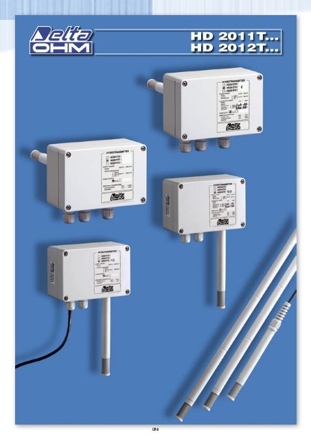
<strong>HD</strong> <strong>2011T</strong>...<br />
<strong>HD</strong> <strong>2012T</strong>...
ACTIVE HUMIDITY AND HUMIDITY-TEMPERATURE TRANSMITTERS<br />
WITH CONFIGURABLE TEMPERATURE WORKING RANGE<br />
Description<br />
The <strong>HD</strong> <strong>2011T</strong>... and <strong>HD</strong> <strong>2012T</strong>... are microprocessor-controlled active humidity and humiditytemperature<br />
transmitters. The temperature range is configurable.<br />
These transmitters convert the humidity and temperature values into two linear current or<br />
voltage signals. Linearisation, with a digital technique, allows excellent precision and stability<br />
to be obtained. Each output of the transmitter may be selected between 0...20mA, 4...20mA or<br />
0...10V and is set by means of a jumper.<br />
The absence of trimmers, potentiometers, etc. makes instrument calibration very simple: all<br />
that is required is to press a key while a led indicates any abnormal situations. The humidity<br />
input can be recalibrated using two saturated solution: the first with 75%R.H., the second with<br />
33%R.H. The relative humidity range 0%R.H...100%R.H. is fixed: depending on the solution<br />
used, the value 0%R.H. corresponds to 0mA, 4mA or 0V, while 100%R.H. corresponds to 20mA,<br />
1V or 10V. In the <strong>HD</strong> 2012 model, the user can set the temperature output in any range in the<br />
field -50...+200°C as long as the minimum amplitude is at least 25°C; a led indicates any alarm<br />
situations (temperature outside the set range, temperature sensor broken or short circuiting)<br />
and assists the user in the programming phase.<br />
Important note: the relative humidity sensor can work in the temperature range -40...+150°C.<br />
Beyond this range the transmitter can work till +180°C for brief periods or in a special<br />
execution<br />
Technical data (@ 20°C and 24Vac)<br />
<strong>HD</strong> <strong>2011T</strong>...<br />
<strong>HD</strong> <strong>2012T</strong>...<br />
Sensor model MK 33<br />
Capacity<br />
300pF typ.<br />
Accuracy at 20°C<br />
±2% (5...90%)<br />
(±2.5% in the remaining field)<br />
Relative humidity work range<br />
5...98%R.H.<br />
Temperature work range of<br />
the relative humidity sensor<br />
-40...+150°C - compensated<br />
Cable length<br />
TC Version = 1.5 m, 5 m and 10 m<br />
Sensor maximum<br />
working pressure<br />
static<br />
20bar<br />
During use, check the compatibility of the sensor with the atmosphere in which it is installed<br />
Sensor ---- Pt100, 100Ω at 0°C (α=0.00385)<br />
Connection ---- with 3 (o 2) leads<br />
Energising of the<br />
transducer<br />
----
or cooling of the air cause a decrease or an increase of the relative humidity (with the same<br />
amount of water vapour present), near doors, in the presence of draughts or in areas where<br />
there is no movement of air.<br />
During use, check the compatibility of the sensor with the atmosphere in which it is<br />
installed.<br />
Assembly<br />
The instrument is offered in three different configurations to satisfy every application<br />
requirement. These are:<br />
TO horizontal version, generally for installation in a channel; a sliding joint is available for fixing<br />
in channels or on walls with a 1/2” gas thread;<br />
TV vertical version for installation on the wall;<br />
TC version with cable. The probe is connected to the electronics by means of a cable of various<br />
lengths and it may operate in a temperature range of -40...+150°C.<br />
Attention: in TC models the sensor and the electronics have the same serial number, they<br />
cannot be exchanged with other transmitters unless the instrument is recalibrated in line<br />
with the new probe.<br />
Programming<br />
The transmitters of the series <strong>HD</strong> <strong>2011T</strong>... and <strong>HD</strong> <strong>2012T</strong>... are equipped with a calibrated<br />
relative humidity probe and temperature probe. The humidity and temperature outputs can<br />
each be selected, independently, with a jumper between 0mA...20mA, 4mA...20mA or 0V...10V.<br />
When it leaves the factory the transmitter is already set as follows:<br />
Holder <strong>HD</strong> 9008.21.2 + <strong>HD</strong> 9008.26/14 125 mm.<br />
Relative humidity 4mA → 0%R.H. 20mA → 100%R.H.<br />
Temperature 4mA → 0°C 20mA → 100°C<br />
The user can recalibrate the humidity probe, as long as he maintains the correspondence 4mA<br />
(or 0mA or 0V) = 0%R.H. and 20mA (or 10V) = 100%R.H. while he can set a different range for<br />
the temperature output (-50...+200°C).<br />
A) Calibration of the humidity probe<br />
The following procedure refers to the output set for a current of 4...20mA: for the other outputs it<br />
is sufficient to shift the jumper before starting the calibration operation.<br />
The following accessories are required:<br />
• a source of alternating power supply at 24Vac or 230Vac depending on the models (check the<br />
data on the plate);<br />
• a precision ammeter with a minimum range 0÷25mA.<br />
Calibration of the humidity probe is carried out on two fixed points: the first point is always<br />
75.4%R.H. and the second point is always 33%R.H., proceeding as follows:<br />
• supply power to the instrument as shown in the wiring diagrams in Fig.1 (<strong>HD</strong> <strong>2011T</strong>...) and<br />
Fig.2 (<strong>HD</strong> <strong>2012T</strong>...);<br />
• insert the probe in the container with the 75%R.H. saturated solution and wait at least 30<br />
minutes;<br />
• move the jumper from “MEASURE” position to “CAL 75%” position;<br />
• press the key marked “Program switch R.H.” and hold it down for at least 5 seconds until the<br />
corresponding led starts to blink. At this point it is possible to release the key: the led remains<br />
lit. A sensor inserted in the probe compensates the temperature difference of the solution with<br />
respect to 20°C;<br />
• insert the probe in the container with the 33%R.H. and wait at least 30 minutes;<br />
• move the jumper to “CAL 33%” position;<br />
• press the key marked “Program switch R.H.” and hold it down for at least 5 seconds until<br />
the corresponding led goes out. At this point it is possible to release the key, the ammeter<br />
will indicate a current of 9.28mA if the solution is at 20°C. If the solution is at a different<br />
temperature, the current indicated by the ammeter will be equal to the value shown in the<br />
following table:<br />
Holder <strong>HD</strong> 9008.21.1 + <strong>HD</strong> 9008.26/14 250 mm.<br />
°C 10 15 20 25 30 35 40 45 50<br />
%R.H. 33.4 33.3 33 32.7 32.4 32 31.6 31.1 30.5<br />
mA 9.34 9.33 9.28 9.23 9.18 9.12 9.06 8.98 8.88<br />
• return the jumper to “MEASURE” position. This concludes calibration of the R.H. probe.<br />
Important note: the first calibration point must always be 75%R.H.<br />
B) Programming the temperature output 4-20mA for <strong>HD</strong> <strong>2012T</strong>... models<br />
The following procedure refers to the output set for a current of 4...20mA: for the<br />
other outputs it is sufficient to shift the jumper before starting the calibration operation.<br />
The following accessories are required:<br />
• a source of alternating power supply at 24Vac or 230Vac depending on the models (check the<br />
data on the plate);<br />
• Pt100 calibrator or a set of precision resistances;<br />
• a precision ammeter with a minimum range 0...25mA.<br />
Procedure<br />
• Connect the temperature section of the <strong>HD</strong> <strong>2012T</strong>... as shown in Fig.2, set the Pt100 calibrator<br />
at the temperature corresponding to 4mA. For example, supposing you want to set the range<br />
-10...+120°C, the calibrator will be set at -10°C: the equivalent resistance value will be 96.09Ω; if<br />
calibration is performed with a fixed resistance, a fixed resistance with a value of 96.09Ω will be<br />
connected between the terminals 11 and 12, with the terminals 10 and 11 short circuiting.<br />
• Wait 10 seconds until the measurement has stabilised, hold down “Program switch °C” for at<br />
Flange with sensor block <strong>HD</strong> 9008.31<br />
least 5 seconds until the LED blinks once and remains lit.<br />
• Set the Pt100 calibrator at the temperature value contemplated for 20mA. According<br />
to the example above, the calibrator will be set at +120°C: the equivalent resistance value will<br />
be 146.07Ω; if calibration is performed with a fixed resistance, a fixed resistance with a value<br />
of 146.07Ω will be connected between the terminals 11 and 12, with the terminals 10 and 11<br />
short circuiting.<br />
• Wait 10 seconds until the measurement has stabilised, hold down “Program switch °C” for at<br />
least 5 seconds until the LED goes out. When the key is released the led blinks twice to confirm<br />
that programming has been completed. At this point the procedure is ended.<br />
• Check that the setting corresponds to the required specifications, setting the calibrator (or<br />
connecting the precision resistances) at the values corresponding to 4 and 20mA and checking<br />
the current in the ammeter.<br />
UR-10
Order codes<br />
<strong>HD</strong> 2011 TO/1: Active relative humidity transmitter, output 0...20mA, 4...20mA or 0...10V.<br />
Horizontal fixed probe for channel installation L=130 mm.<br />
<strong>HD</strong> 2011 TO/2: Active relative humidity transmitter, output 0...20mA, 4...20mA or 0...10V.<br />
Horizontal fixed probe for channel installation L=330 mm.<br />
<strong>HD</strong> 2011 TO/3: Active relative humidity transmitter, output 0...20mA, 4...20mA or 0...10V.<br />
Horizontal fixed probe for channel installation L=530 mm.<br />
<strong>HD</strong> 2011 TV: Active relative humidity transmitter, output 0...20mA, 4...20mA or 0...10V. Vertical<br />
fixed probe for wall installation<br />
<strong>HD</strong> 2011 TC/1: Active relative humidity transmitter, output 0...20mA, 4...20mA or 0...10V. Probe<br />
L=130 mm for direct connection to the instrument with a cable L=1.5 metres.<br />
<strong>HD</strong> 2011 TC/2-5: Active relative humidity transmitter, output 0...20mA, 4...20mA or 0...10V.<br />
Probe L=330 mm for direct connection to the instrument with a cable L=5 metres.<br />
<strong>HD</strong> 2011 TC/2-10: Active relative humidity transmitter, output 0...20mA, 4...20mA or 0...10V.<br />
Probe L=330 mm for direct connection to the instrument with a cable L=10 metres.<br />
<strong>HD</strong> 2012 TO/1: Double active relative humidity and temperature transmitter for channel<br />
installation, double output 0...20mA, 4...20mA or 0...10V. Horizontal fixed probe for<br />
channel installation L=130 mm.<br />
<strong>HD</strong> 2012 TO/2: Double active relative humidity and temperature transmitter for channel<br />
installation, double output 0...20mA, 4...20mA or 0...10V. Horizontal fixed probe for<br />
channel installation L=330 mm.<br />
<strong>HD</strong> 2012 TO/3: Double active relative humidity and temperature transmitter for channel<br />
installation, double output 0...20mA, 4...20mA or 0...10V. Horizontal fixed probe for<br />
channel installation L=530 mm.<br />
<strong>HD</strong> 2012 TV: Double active relative humidity and temperature transmitter, double output<br />
0...20mA, 4...20mA or 0...10V. Vertical fixed probe for wall installation.<br />
<strong>HD</strong> 2012 TC/1: Double active relative humidity and temperature transmitter for channel<br />
installation, double output 0...20mA, 4...20mA or 0...10V. Probe L=130 mm for direct<br />
connection to the instrument with a cable L=1.5 metres.<br />
<strong>HD</strong> 2012 TC/2-5: Double active relative humidity and temperature transmitter for channel<br />
installation, double output 0...20mA, 4...20mA o 0...10V. Probe L=330 mm for direct<br />
connection to the instrument with a cable L=5 metres.<br />
<strong>HD</strong> 2012 TC/2-10: Double active relative humidity and temperature transmitter for channel<br />
installation, double output 0...20mA, 4...20mA o 0...10V. Probe L=330 mm for direct<br />
connection to the instrument with a cable L=10 metres.<br />
<strong>HD</strong>75: saturated salt solution 75% R.H. with adapter M 12x1<br />
<strong>HD</strong>33: saturated salt solution 33% R.H. with adapter M 12x1<br />
<strong>HD</strong>9008.21.1: holder for vertical sensor, wall distance 250mm, hole Ø 26.<br />
Use with reduction <strong>HD</strong>9008.26.14<br />
<strong>HD</strong>9008.21.2: holder for vertical sensor, wall distance 125mm, hole Ø 26.<br />
Use with reduction <strong>HD</strong>9008.26.14<br />
<strong>HD</strong>9008.26/14: reduction for Ø 26 and Ø 14mm holes, for <strong>HD</strong>9008.21.1 and <strong>HD</strong>9008.21.2<br />
<strong>HD</strong>9008.31: flange with sensor block Ø 14mm for duct sensors of the series TC and TO.<br />
On request the transmitters can be supplied with voltage output 0...1Vdc or 0...5Vdc.<br />
Examples of connection of the transmitters <strong>HD</strong> <strong>2011T</strong>... and <strong>HD</strong> <strong>2012T</strong>...<br />
with the indicators <strong>HD</strong> 9022 and DO 9404<br />
<br />
<br />
<br />
<br />
<br />
<br />
<br />
<br />
RL1 RL2 RL3 RL4 RL5<br />
<br />
<br />
<br />
<br />
IN2 +15V GND VIN1<br />
GND VIN2 -5V IN1 +15V<br />
<br />
12...24Vac<br />
<br />
<br />
<br />
<br />
<br />
<br />
<br />
<br />
<br />
<br />
<br />
<br />
<br />
<br />
<br />
<br />
<br />
<br />
<br />
%RH<br />
C<br />
Fig. 11 <strong>HD</strong> <strong>2012T</strong>... configured with current output 4...20mA connected to the double<br />
indicator regulator DO 9404.<br />
<strong>HD</strong> 9022 / %RH<br />
<br />
<br />
<br />
Fig. 7 Mechanical dimensions version TO.<br />
<br />
<br />
<br />
12...24Vac<br />
<br />
<br />
IN<br />
GND<br />
<br />
<br />
<br />
<br />
<br />
<br />
<br />
<br />
<br />
<strong>HD</strong> 9022 / C<br />
<br />
<br />
<br />
<br />
<br />
<br />
<br />
12...24Vac<br />
%RH<br />
GND<br />
IN<br />
<br />
Fig. 12 <strong>HD</strong> <strong>2012T</strong>... configured with current output 4...20mA connected to two<br />
indicator regulators <strong>HD</strong> 9022.<br />
Examples of connection of the transmitters <strong>HD</strong> <strong>2011T</strong>... and <strong>HD</strong> <strong>2012T</strong>... with<br />
the indicators <strong>HD</strong> 404 and <strong>HD</strong> 4049<br />
C<br />
<br />
<br />
Fig. 8 Mechanical dimensions version TV.<br />
<br />
<br />
12...24Vac<br />
<br />
<br />
<br />
<br />
<br />
<br />
<br />
<br />
<br />
<br />
<br />
<br />
<br />
<br />
<br />
12...24Vac<br />
<br />
The Temperature configuration of the transmitter <strong>HD</strong> <strong>2012T</strong>... has to be the same<br />
as the <strong>HD</strong> 404: 4mA = -20°C...20mA = +80°C.<br />
Fig. 14 <strong>HD</strong> <strong>2012T</strong>... configured with current output 4...20mA connected to a relative<br />
humidity regulator <strong>HD</strong> 4049 and to a temperature regulator <strong>HD</strong> 404 - <strong>HD</strong> <strong>2012T</strong>...<br />
%RH<br />
C<br />
UR-11<br />
<br />
<br />
<br />
<br />
<br />
<br />
Fig. 9 Mechanical dimensions version TC.