Flexible, Reliable Substation Automation & Control ... - Belmet
Flexible, Reliable Substation Automation & Control ... - Belmet
Flexible, Reliable Substation Automation & Control ... - Belmet

You also want an ePaper? Increase the reach of your titles
YUMPU automatically turns print PDFs into web optimized ePapers that Google loves.
D25<br />
Multifunction Bay <strong>Control</strong>ler/RTU<br />
<strong>Substation</strong> <strong>Automation</strong><br />
<strong>Flexible</strong>, <strong>Reliable</strong> <strong>Substation</strong><br />
<strong>Automation</strong> & <strong>Control</strong><br />
KEY BENEFITS<br />
• <strong>Flexible</strong> IEC 61850 Server provides easy integration of<br />
substation automation systems without the need to replace<br />
any existing equipment<br />
• Advanced IEC 61131-3 compliant PLC logic engine eliminates<br />
the need for additional PLCs or other automation devices<br />
• Support for industry standard SCADA protocols ensures<br />
easy integration into new or existing systems, reducing<br />
engineering time & costs<br />
• Easy-to-use front touch-screen HMI eliminates the need for<br />
additional local bay control units<br />
APPLICATIONS<br />
• Communications and data concentrator<br />
• Advanced automation controller<br />
• Advanced Power quality monitoring and digital fault<br />
recording capabilities eliminate the need for separate devices<br />
• Manages and preserves all event and original I/O time tags<br />
for reliable sequence of events recording<br />
• Redundant I/O monitoring and management for bay control,<br />
reduces the number of I/O required by master stations<br />
• Advanced transformer monitoring and control ensures<br />
optimized loading and extended equipment life<br />
• Embedded high-current control eliminates the need for<br />
separate interposing relay panels<br />
• Metering, sequence of events & fault recording device<br />
• Transformer monitoring and controller<br />
FEATURES<br />
Advanced <strong>Automation</strong> & <strong>Control</strong><br />
• Synchronism check<br />
• Dynamic bus switching<br />
• Auto-restoration schemes<br />
• Load shedding schemes<br />
• PLC logic programming (LogicLinx)<br />
• AC analog alarming<br />
Communications<br />
• Local Remote Unit (LRU) allowing for multiple masters and<br />
slaves communicating multiple SCADA protocols<br />
• Protocol conversion from legacy to modern industry standard<br />
• Redundant Ethernet, fiber, or copper communications<br />
• RS232/RS485 with up to 4 software configurable channels<br />
• IEC 61850 Server<br />
• GOOSE/GSSE messaging<br />
g<br />
Digital<br />
Energy<br />
Metering & Recording<br />
• Advanced digital fault recording<br />
• 1ms time tag preservation<br />
• Harmonic spectrum up to 21st harmonic<br />
• Power quality monitoring including sags and swells<br />
• Graphical, touch-screen HMI with alarms and one-line<br />
diagrams<br />
• AC profiling of all inputs<br />
Transformer Monitoring and <strong>Control</strong><br />
• Cooling control module<br />
• Cooling efficiency model<br />
• Moisture model<br />
• Dynamic loading model<br />
• Winding hot spot analysis model<br />
• Insulation aging model<br />
1
D25 Multifunction Bay <strong>Control</strong>ler/RTU<br />
<strong>Substation</strong> <strong>Automation</strong><br />
<strong>Substation</strong> <strong>Automation</strong><br />
<strong>Control</strong>ler<br />
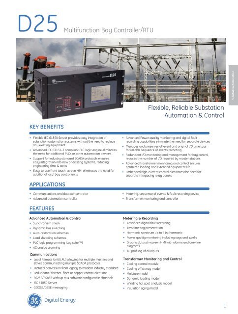
GE’s D25 is a flexible, modular, and compact<br />
RTU, suitable for both large and small<br />
substation automation projects. Designed<br />
to act as a local data concentrator with its<br />
capabilities to communicate in more than<br />
120 different SCADA protocols including<br />
IEC 61850. Along with a set of flexible,<br />
expandable and customizable I/O including<br />
A/C inputs, GE’s D25 can fulfill the role of a<br />
complete bay level controller RTU. The D25<br />
provides advanced tools and the flexibility<br />
necessary for applications such as load<br />
shedding, digital fault recording, power<br />
quality monitoring, metering, transformer<br />
monitoring & control, or custom PLC logic.<br />
D25 Communications<br />
Enterprise Systems<br />
<strong>Substation</strong><br />
D25<br />
The collected substation device data is moved up to<br />
EMS and DMS SCADA systems providing centralized<br />
management of substation switches and breakers.<br />
Local HMI/<br />
Single Line<br />
The D25 provides the tools and flexibility<br />
necessary to create customized<br />
automation control applications including<br />
• Communications & data concentrator<br />
• <strong>Automation</strong> controller<br />
• Metering, sequence of events & fault<br />
recording<br />
• Tranformer monitoring & control<br />
Protection<br />
Relay<br />
Transformer<br />
Diagnostics<br />
Power Quality<br />
Meter<br />
Motor<br />
Manager<br />
Third party<br />
device<br />
Communications and<br />
Data Concentrator<br />
Protocol Conversion<br />
With a communications suite that supports<br />
over 120 protocols, including IEC® 61850,<br />
Modbus®, DNP, SPABus, Courier, and<br />
IEC 101/103/104, the D25 supports the<br />
translation of multiple protocols over<br />
multiple communication ports enabling<br />
easy integration of new and existing<br />
devices into supervisory and control<br />
systems (SCADA).<br />
<strong>Flexible</strong> IEC 61850<br />
The D25 IEC 61850 server application<br />
allows data from the unit to be modeled<br />
and presented as IEC 61850 Logical<br />
Node data. The data can come form<br />
any of the D25’s internal applications or<br />
from devices connected using supported<br />
communication protocols. This powerful<br />
conversion tool allows data from non-<br />
IEC61850 devices to be modeled into<br />
61850 data for transmission upstream,<br />
eliminating the need to replace older or<br />
legacy devices for IEC 61850 compliance.<br />
KEMA ® certified as a IEC 61850 compliant<br />
device, the D25 includes additional IEC<br />
61850 features such as Security <strong>Control</strong>s<br />
and Buffered <strong>Control</strong> Blocks , which do not<br />
exist in most bay-level equipment.<br />
With native support for IEC 61850<br />
GOOSE, the D25 provides Peer-to-Peer<br />
communications between D25s and other<br />
GOOSE enabled devices in the system. GE’s<br />
D25 supports both fixed and configurable<br />
GOOSE messaging (data sets), ensuring<br />
connectivity to a wide range of protection<br />
devices including the Multilin UR & URPlus<br />
Families of protection & control devices.<br />
GE’s D25 meets IEC 61850 Class P2/3<br />
performances levels required for timely<br />
interlocking schemes.<br />
Local Remote Unit (LRU)<br />
Local Remote Unit (LRU) allows the D25<br />
device to abstract a portion of its database<br />
and make it available to selected master<br />
stations, with the D25 presented as<br />
multiple slave devices. The same concept<br />
applies to slave devices (or servers), where<br />
the D25 can act as multiple master stations<br />
and retrieve data as needed. The flexibility<br />
and LRU concept allow the D25 to act as a<br />
gateway and data concentrator.<br />
Ethernet-ready<br />
The D25 supports standard communication<br />
methods over Ethernet, including Telnet<br />
and TFTP, but more importantly GE’s D25<br />
units can also extend your LAN to legacy<br />
devices by providing a virtual connection<br />
to devices that do not have Ethernet<br />
capability, enabling you to perform remote<br />
configuration changes over a Ethernet<br />
network.<br />
2<br />
www.GEDigitalEnergy.com
D25 Multifunction Bay <strong>Control</strong>ler/RTU<br />
<strong>Flexible</strong> <strong>Substation</strong> Communications & <strong>Control</strong><br />
<strong>Substation</strong> <strong>Automation</strong><br />
Enterprise Systems<br />
CT/VT Connections<br />
Status <strong>Control</strong><br />
Device Communications<br />
Advanced <strong>Automation</strong> &<br />
<strong>Control</strong><br />
Synchronism Check<br />
The D25 supports the Synchcheck<br />
functions, including a synchronism bypass<br />
function for any or all of the following<br />
conditions:<br />
• Dead Line – Live Bus<br />
• Dead Bus – Live Line<br />
• Dead Bus – Dead Line<br />
The D25 monitors the voltage difference,<br />
phase angle difference, and slip frequency<br />
to ensure proper breaker closure per<br />
specific user-defined settings.<br />
Dynamic Bus Switching<br />
The D25 supports multiple buses per feeder,<br />
where each bus is defined by a set of PTs<br />
and a digital input (referred to as Active<br />
Bus Indication) that indicates when the bus<br />
is active on that feeder. The D25 monitors<br />
the Active Bus Indications to determine<br />
which set of PTs to use for the feeder.<br />
This unique ability allows for dual-busbar<br />
schemes to be reconfigured dynamically,<br />
maintaining a system-metering scheme<br />
without requiring an external voltage<br />
selection scheme.<br />
Auto Restoration<br />
Focused on improving power system<br />
reliability, the D25 enables advanced<br />
auto restoration schemes. Applicable<br />
to groups of two feeders joined by a Tie<br />
Switch with each having one breaker<br />
and up to three feeder switches, the D25<br />
can accommodate up to 255 concurrent<br />
restorations with separate definitions on<br />
each feeder. This application makes the<br />
D25 a [powerful auto-restoration device<br />
that is fully flexible and customizable.<br />
Load Shedding<br />
The D25 can be equipped with a robust and<br />
configurable load shedding algorithm. The<br />
application monitors digital input states<br />
and digital output requests related with<br />
zones and groups in order to automatically<br />
control selected feeders, optimizing system<br />
loading for improved system reliability and<br />
asset life. All application timing and other<br />
configuration parameters are customizable<br />
and can be changed online.<br />
Mathematical <strong>Control</strong> Logic<br />
Using the Calculator tool, users can create<br />
advanced solutions that group, manage<br />
and control points to produce the required<br />
automation results.<br />
The calculator tool can perform<br />
mathematical, logical, or timer based<br />
operations on any data points stored<br />
in the D25. Using a graphical interface,<br />
users can define logical expressions using<br />
mathematical functions such as addition,<br />
multiplication, logarithm, greater than, less<br />
than, as well as other boolean functions.<br />
Programmable Logic (LogicLinx)<br />
For more advanced applications, GE’s<br />
programmable logic (LogicLinx) software<br />
provides PLC functionality on the D25<br />
platform. LogicLinx offers textual and<br />
graphical languages as defined in the IEC<br />
61131-3 standard for PLC programming<br />
environments, including Sequential<br />
Functions Chart, Instruction List, Structured<br />
Text, Ladder Diagram, and Function Block<br />
Diagram. In addition, a wide range of<br />
arithmetic, Boolean and logical operations<br />
are supported.<br />
AC Analog Alarming<br />
When deployed in advanced AC Monitoring<br />
applications, the D25 provides extensive<br />
and configurable alarming capability for<br />
AC analog values such as configurable<br />
hysteresis parameters.<br />
www.GEDigitalEnergy.com<br />
3
D25 Multifunction Bay <strong>Control</strong>ler/RTU<br />
<strong>Substation</strong> <strong>Automation</strong><br />
Metering, Sequence of<br />
Events & Fault Recording<br />
With a high-density of communication<br />
channels, analog, and digital I/O modules,<br />
the D25 provides real-time data acquisition<br />
and recording functions. The D25 is<br />
capable of recording oscillography files<br />
and performing 1, 2, 2 ½, and 3-element<br />
metering on separate or bussed feeders,<br />
up to a maximum of four three-phase<br />
feeders delivering system visibility for<br />
utility operators and maintenance staff<br />
Sequence of Events<br />
The D25 manages and preserves all<br />
events and original I/O time tags, with<br />
1 ms accuracy, using a state-of-the-art<br />
database. Data accuracy is critical to<br />
ensure accurate and reliable fault analysis,<br />
to enable a more stable power system<br />
through positive corrective actions.<br />
Transformer Fault Recorded by a D25<br />
Digital Fault Recording<br />
When activated by user-configurable<br />
trigger conditions, the D25 Digital Fault<br />
Recording software captures current and<br />
voltage waveforms as well as status from<br />
analog and digital channels. Up to 250<br />
digital status inputs can be recorded and<br />
combined with 240 cycles of waveform<br />
data in standard COMTRADE files. The<br />
software stores up to 16 MB of fault data<br />
locally for subsequent retrieval via multiple<br />
protocols such as TFTP or DNP3.<br />
Harmonic Spectrum<br />
The D25 can provide harmonic values (up<br />
to the 21st) on every AC Analog input and<br />
make it available to a control center. Values<br />
such as total harmonic distortion are also<br />
calculated and made available.<br />
Power Quality<br />
The D25 can monitor power quality and<br />
profile RMS values for up to 5 separate<br />
AC circuits. It has the ability to detect<br />
and report short-duration and extendedduration<br />
voltage swells, sags, harmonics,<br />
harmonic distortion, and interruptions<br />
and also records the RMS voltage profiles<br />
of those events as COMTRADE format files<br />
for simplified power system analysis and<br />
troubleshooting<br />
Graphical Display Panel (HMI)<br />
This easy-to-use touch screen panel can<br />
be configured as a fully functional local<br />
HMI with features such as interlocking,<br />
password control, metering, and SOE /<br />
alarm annunciator screens. Individual<br />
screens in the graphical display can<br />
be customized to meet the unique<br />
requirements for each application.<br />
AC Profiling<br />
Record any AC analog value and store it in<br />
COMTRADE format. Record definitions can<br />
be customized for almost any scenario<br />
and can be triggered by a digital input.<br />
Data can be captured for as long as 5400<br />
cycles, providing a complete, accurate<br />
view of the system.<br />
Transformer Monitoring<br />
The D25 utilized in Transformer Monitoring<br />
applications is a condition analysis and<br />
management system for critical power<br />
transformers. This system measures<br />
key transformer data, implements<br />
continuous on-line analysis models, and<br />
communicates critical information through<br />
the communication options supported by<br />
the D25.<br />
On-line analysis models include:<br />
• Load Current Model<br />
• Cooling System Efficiency Model<br />
• Winding Hottest Spot Model<br />
• Insulation Aging Model<br />
• Cooling <strong>Control</strong> Model<br />
• Minute Average Apparent Power Model<br />
• OLTC Temperature Differential Model<br />
• Moisture Model<br />
• On-Line Dynamic Loading Model The<br />
dynamic loading model incorporates<br />
outputs from the other models as well<br />
as key<br />
The dynamic loading model provides the<br />
system operator with a perspective of the<br />
overloading capabilities of the transformer.<br />
Among other transformer sensors, the D25<br />
provides seamless integration with GE’s<br />
Hydran* to optimize equipment output<br />
and extend asset life.<br />
4<br />
www.GEDigitalEnergy.com
D25 Multifunction Bay <strong>Control</strong>ler/RTU<br />
Hardware<br />
<strong>Flexible</strong> Modular I/O<br />
The D25 includes a modular system<br />
to increase its I/O capacity. It can<br />
accommodate up to 96 digital inputs, 32<br />
digital outputs, 32 analog inputs (DC), and<br />
15 AC inputs to monitor 3-phase circuits.<br />
The D25 can also support single/double<br />
digital points and accumulators.<br />
All I/O is monitored and recorded at a 1<br />
ms resolution. To ensure data accuracy,<br />
the D25 can be time synchronized through<br />
IRIG-B, SNTP, or most SCADA protocols.<br />
Fluxbuster AC analog inputs<br />
This technology enables accurate postfault<br />
analysis. The D25 can monitor and<br />
record current waveform levels up to 42<br />
nominal values. This guarantees accurate<br />
recording of symmetrical fault current<br />
waveforms. The Fluxbuster technology<br />
does not sacrifice accuracy in order to<br />
provide a wide input range unlike many<br />
other protection devices. The Fluxbuster<br />
technology provides unparalleled accuracy<br />
of up to 0.3% of nominal (0.3% of nominal<br />
from 2% – 195% measurement range<br />
and 1.0% of nominal from 195% – 4200%<br />
measurement range).<br />
High Current <strong>Control</strong> Card<br />
The D25 can be equipped with a digital<br />
output module comprising of 32 relays,<br />
each rated at 10 A for 5 seconds and 4 A<br />
continuously. This can eliminate the need<br />
for separate interposing relays, reducing<br />
cost and saving valuable space within<br />
cabinets.<br />
Scalable Analog Adapters<br />
The D25 includes an optional customizable<br />
32-point analog input card with multiple<br />
analog adapters. This enables you to pick<br />
and choose multiple types of DC analog<br />
inputs to meet a wide range of current<br />
and voltage requirements. Adapters can<br />
be changed in the field simply by plugging<br />
a different adapter on the module..<br />
Digital Inputs<br />
96 inputs are available with chatter filter<br />
to eliminate unwanted alarms. Singlepoint,<br />
double-point and accumulators<br />
can be configured using digital inputs.<br />
The wetting voltage of digital inputs can<br />
also be selected to meet site-specific<br />
requirements.<br />
Manage Redundant I/O<br />
The D25 is capable of managing redundant<br />
I/O based on the operational status of each<br />
device. The D25 can also maintain control<br />
functionality by redirecting a command to<br />
the final destination. This feature is unique<br />
within the GE Digital Energy suite of devices<br />
and allows for an easier integration with<br />
master stations.<br />
<strong>Substation</strong> <strong>Automation</strong><br />
Back Panel<br />
Easily replaceable fuses<br />
Time Synchronization Input & Serial<br />
Communications Channels (RS 232 or<br />
RS 485, software selectable)<br />
Dual Redundant Fiber or<br />
Copper Ethernet Link<br />
Digital Inputs<br />
(3 groups of 32 inputs)<br />
DC Analog Inputs supporting voltage &<br />
current inputs of different ranges<br />
5 AC Inputs (Variety of CT/PT<br />
options available<br />
32 Digital Outputs<br />
www.GEDigitalEnergy.com<br />
5
D25 Multifunction Bay <strong>Control</strong>ler/RTU<br />
Technical Specifications<br />
<strong>Substation</strong> <strong>Automation</strong><br />
Port Configurations<br />
AC Analog Inputs: 0, 3, 6, 9, 12 or 15 inputs<br />
DC Analog Inputs: 0 or 16 inputs<br />
Digital Status Inputs: 0 to 96 inputs in increments of 32<br />
<strong>Control</strong> Outputs: 0, 16, or 32 trip/close pairs or 32 isolated high current<br />
outputs with 8 optional current supervision<br />
Host Comm Ports: 2 serial (38.4 Kbps) or 2 Ethernet (10 Mbps)<br />
IED Comm Ports: 2 (38.4 Kbps)<br />
Time Sync: 1 IRIG-B Input<br />
Configuration Port: 1 Maintenance port<br />
Display: 1 D25 Display Port (9600 bps)<br />
Power Requirements<br />
Input Options:<br />
Maximum Power<br />
Consumption:<br />
Maximum Inrush<br />
Current on Cold Start:<br />
Maximum Inrush<br />
Current under<br />
Dynamic Conditions 1:<br />
Communication Ports<br />
Maintenance Port:<br />
D25 Display Port:<br />
UTC Time Port:<br />
Standard Serial Comm.<br />
Ports (2):<br />
Optional Comm.<br />
Ports (2):<br />
AC Analog Value<br />
Measurement<br />
Configuration Options:<br />
20-60 Vdc<br />
60-150 Vdc/85-135 Vac 50/60 Hz (CE)<br />
150-350 Vdc/187-265 Vac 50/60 Hz (CE)<br />
65 W<br />
18 A (peak Amps)<br />
45 A (peak Amps)1<br />
WESMAINT II+ DB-9-F, RS-232 @ 9600 bps<br />
DB-9-F, RS-485 @ 9600 bps<br />
DB-9-F, RS-232/RS-422<br />
DB-9-F, RS-232/485 up to 38400 bps<br />
DB-9-F, RS-232/485 up to 38400bps, software<br />
configurable or Ethernet/802.3 10BASE-T or 10BASE-FL<br />
Direct AC analog inputs from CTs and PTs. Supports<br />
up to six 3-phase circuits Scaling factors are provided<br />
to allow fine-tuning of the nominal values of the AC<br />
inputs to match the actual nominal values of the field<br />
sources.<br />
Analog Inputs: 15 AC analog inputs organized in groups of three (3)<br />
inputs, Transformer isolated<br />
Sampling Rate:<br />
64 samples per Power Line Cycle<br />
A/D Resolution: 13 bits plus sign<br />
AC Voltage Inputs<br />
Nominal PT Input 63.5 Vrms, 69.3 Vrms, 110 Vrms, 120 Vrms, 220 Vrms<br />
Options:<br />
Measurement Range: 0% to 250% of nominal<br />
Overload Voltage: 250% of nominal continuous<br />
350% of nominal for one (1) minute<br />
Burden:<br />
Less than 0.1 VA @ nominal input<br />
Accuracy 2:<br />
±0.5 % of nominal<br />
Frequency:<br />
±0.01 Hz<br />
Phase angle: ±0.5°<br />
AC Current Inputs<br />
Nominal CT Input<br />
Options:<br />
Measurement Range:<br />
Thermal Overload:<br />
1 A rms or 5 A rms<br />
2% to 1600% of nominal for value measurement<br />
2% to 4200% (asymmetrical) of nominal for DFR and<br />
protection<br />
4 times nominal – continuous<br />
30 times nominal – 10 seconds<br />
100 times nominal – 1 second<br />
10 minute duty cycle for inputs greater than 4 times<br />
nominal<br />
Burden:<br />
Accuracy 2 :<br />
General AC Features<br />
RMS Data:<br />
Metering:<br />
Power Quality:<br />
Electrical Energy:<br />
Unbalance Detection:<br />
Alarming:<br />
Line Frequency:<br />
Oscillography:<br />
Per-cycle Data<br />
Logging:<br />
Protection:<br />
Accuracy 2:<br />
16x 1A & 5A CT – Less than 0.2VA @ nominal input. 42x<br />
1A CT – Less than 0.05 VA @ nominal input.<br />
42x 5A CT – Less than 0.1 VA @ nominal input.<br />
16x 1A & 5A CT- ±0.5% of nominal<br />
42x 1A & 5A CT- ±0.3% of nominal<br />
Frequency ±0.03 Hz<br />
Phase angle ±0.5°<br />
DC Analog Value Measurement<br />
Configuration Options:<br />
Analog Inputs:<br />
Sampling Rate:<br />
A/D Resolution:<br />
DC Current<br />
RMS magnitudes and phase angles for measured<br />
inputs. Supports L-L or L-N PT connections with<br />
calculation of L-L or L-N magnitudes and phase angles<br />
Electrical Power supports 1, 2, 21/2 and 3 element<br />
metering providing active, reactive, and apparent<br />
power; power factor per phase and circuit totals. Also<br />
provides displacement power factor angle per phase<br />
THD and harmonic spectrum data to the 21st<br />
harmonic for each AC input<br />
Import and export accumulators for kWh, kVAh, kVArh<br />
Symmetrical component circuit unbalance detection<br />
and maximum deviation from average methods<br />
High and low alarms on any analog data with<br />
qualifications of one power cycle or more<br />
50/60 Hz<br />
Waveform and event recording on up to 15 AC analog<br />
channels simultaneously with concurrent capture<br />
of up to 250 digital input points Analog sample rate:<br />
64 samples/cycle Record length: 240 cycles with<br />
programmable pre- and post-capture times<br />
Capturing selected AC values and digital data every<br />
power cycle<br />
3-step definite time over-current protection and<br />
breaker failure protection on all configured circuits<br />
Active/reactive/apparent power ±0.96% of nominal<br />
Power factor ±2.85% of FS<br />
Active/reactive energy ±2% of reading<br />
Apparent energy ±0.5% of reading<br />
Scaling factors are provided to allow fine-tuning of the<br />
nominal values of the DC inputs to match the actual<br />
nominal values of the field sources<br />
16 DC analog optically isolated differential inputs<br />
40 samples/second @ 50 Hz; 50 samples per second @<br />
60 Hz; 2 samples are averaged before captured in the<br />
database (effective reporting rate is 20 samples/sec @<br />
50Hz, 25 samples/sec @ 60 Hz<br />
14 bits plus sign<br />
Nominal Input Range ±1 mA, ±5 mA, ±10 mA, or ±20 mA<br />
Options:<br />
Input Burden: 5K to 250Ω (1 to 20 mA)<br />
Accuracy:<br />
±0.10% of full scale<br />
Temperature<br />
±30 ppm/°C<br />
Coefficient:<br />
DC Voltage<br />
Nominal Input Range: ±5 Vdc<br />
Measurement Range: ±6 Vdc<br />
Overload Voltage: ±30 Vdc (NM) continuous, ±200 Vdc (CM) continuous<br />
Input Impedance: More than 10 MΩ<br />
Accuracy:<br />
±0.05% of full scale<br />
Temperature<br />
±15 ppm/°C<br />
Coefficient:<br />
6<br />
www.GEDigitalEnergy.com
D25 Multifunction Bay <strong>Control</strong>ler/RTU<br />
Technical Specifications (Continued)<br />
Digital Inputs<br />
General;<br />
Digital Input Options:<br />
Burden:<br />
Contact Debounce:<br />
Configurable Input<br />
Types:<br />
On-Board Wetting<br />
Supply (not available<br />
with graphical display):<br />
Digital Outputs (D25KE)<br />
Standard Digital<br />
Outputs:<br />
Configurable Output<br />
Types:<br />
Output Relay Contacts:<br />
Maximum Switching<br />
Power:<br />
Maximum Switching<br />
Voltage:<br />
Maximum Switching<br />
Current:<br />
Maximum Carrying<br />
Current:<br />
Operate Time:<br />
Release Time:<br />
Breakdown Voltage:<br />
Isolation between<br />
Adjacent Outputs:<br />
Interposing Relay<br />
Option:<br />
Up to 96 optically isolated (5000 Vrms), organized in<br />
cards of 32 inputs<br />
One of: 12, 24, 48, 120, 250 Vdc ±20%, bipolar inputs<br />
1.2 to 10 mA, maximum power dissipation is 0.5 W<br />
per input<br />
Three-level programmable software filtering for<br />
debounce and chatter<br />
Digital input, Sequence of Events with time-tagging<br />
accuracy of 1 ms, Change of State, Up to 8 digital<br />
inputs as Pulse Accumulator<br />
24 Vdc or 48 Vdc (depends on supply ordered),<br />
isolated, external wetting optional<br />
16 or 32 relay outputs switch one side of the<br />
controlled load; single component failure protection<br />
and detection preventing false control of any coil<br />
driver output; selectcheck- before execute security;<br />
master trip/master close bus scheme<br />
Latching (On/Off), Trip/Close, Raise/Lower,<br />
Programmable pulse duration from 5 to (2 31 -1) ms in<br />
1 ms intervals<br />
1 Form A<br />
60 W or 125 VA (resistive)<br />
75 Vdc or 50 Vac (DB-25) 120 Vdc (FACE-40)<br />
2 A<br />
2 A<br />
5 ms<br />
5 ms<br />
1500 Vac for one minute (coil to contact)<br />
300 Vdc (with compression terminal block), 100 Vdc<br />
(with DB-25 connectors)<br />
Groups of 8 digital outputs can be directly interfaced<br />
to D20KI module<br />
High Current Digital Outputs (D25HC KE)<br />
Standard Digital<br />
Outputs:<br />
Configurable Output<br />
Types:<br />
Output Relay Contacts:<br />
Maximum Make<br />
Current:<br />
Maximum Continuous<br />
Carrying Current:<br />
Maximum Break<br />
Current:<br />
Maximum Switching<br />
Voltage:<br />
Current Sensing Level<br />
for Seal-In Function:<br />
Operate Time:<br />
Release Time:<br />
Isolation Between<br />
Adjacent Outputs:<br />
Simultaneously<br />
Operated Outputs:<br />
32 isolated digital outputs with single component<br />
failure protection and detection, preventing false<br />
control of any coil driver output; select-check-before<br />
execute security 8 outputs with optional current<br />
supervision seal-in function<br />
Raise/lower, Programmable pulse duration from 5 to<br />
(231-1) ms in 1 ms intervals<br />
8x 1 Form C<br />
16x 1 Form A<br />
8x 1 Form A with optional current seal-in function<br />
10 A for 5 seconds<br />
4 A<br />
10 A @ 28 Vdc<br />
0.85 A @ 60 Vdc<br />
0.45 A @ 120 Vdc<br />
0.3 A @ 300 Vdc<br />
300 Vdc or 300 Vac<br />
Min. 60 mA<br />
Max. 200 mA<br />
7 ms<br />
10 ms<br />
300 Vdc<br />
Maximum 16, includes maximum 4 with current<br />
supervision<br />
Auxiliary Digital Outputs<br />
Radio Keying Output<br />
Relay Contact:<br />
Auxiliary <strong>Control</strong><br />
Output Relay Contacts:<br />
System Fail Relay<br />
Contacts:<br />
Maximum Switching<br />
Power:<br />
Maximum Switching<br />
Voltage:<br />
Maximum Switching<br />
Current:<br />
Maximum Carrying<br />
Current:<br />
Breakdown Voltage:<br />
Available Displays<br />
Alphanumeric:<br />
Graphical:<br />
1 Form A<br />
1 Form A<br />
1 Form B<br />
60 W (resistive), 125 VA<br />
75 Vdc or 50 Vac<br />
2 A<br />
2 A<br />
Physical Specifications<br />
1500 V (coil to contact)<br />
Backlit LCD with keypad<br />
Backlit LCD with touch screen,<br />
320 X 240 pixels, 4.76” X 3.58”<br />
Dimensions:<br />
19” (48cm) Width, 8.75” (22cm) Height, 9” (23cm) Depth<br />
Weight:<br />
31 lbs. (14.1kg) maximum<br />
Operational<br />
-20°C to +70°C (without display), 0°C to +60°C (with<br />
Temperature:<br />
alphanumeric display), 0°C to +50°C (with graphical<br />
display)<br />
Storage Temperature: -40°C to +90°C (without alphanumeric display), -20°C<br />
to +70°C (with alphanumeric display), 0°C to +70°C<br />
(with<br />
graphical display)<br />
Humidity Rating: 0 to 95% relative humidity, non-condensing<br />
Environmental Rating: IP20<br />
Installation/Overvoltage<br />
category:<br />
Class II<br />
Pollution Degree: 2<br />
Product Compliance<br />
EN55011<br />
EN61000-3-2<br />
EN61000-4-2<br />
EN61000-4-3<br />
EN61000-4-4<br />
EN61000-4-5<br />
EN61000-4-6<br />
EN61000-4-8<br />
EN61000-4-11<br />
EN61000-4-12<br />
EN61010-1<br />
IEC® 600068-2-1<br />
IEC 600068-2-2<br />
IEC 600068-2-6<br />
IEC 600068-2-30<br />
IEC 600068-2-31<br />
EN61000-4-16<br />
Limits and methods of measurement of<br />
electromagnetic disturbance characteristics of<br />
industrial, scientific and medical (ISM) radio-frequency<br />
equipment<br />
Limits for Harmonic Current Emissions<br />
(applicable for AC power supply only)<br />
ESD/Immunity Test<br />
Radiated, radio-frequency, electromagnetic field<br />
immunity Test<br />
Electrical Fast Transient/Burst Immunity Test<br />
Surge Immunity Test<br />
Immunity to conducted disturbances induced by<br />
radio-frequency fields<br />
Voltage Dips, Short Interruptions and Voltage<br />
Variations<br />
Immunity Tests (applicable for AC power supplies only)<br />
Oscillatory Waves Immunity Test<br />
Product safety<br />
Cold<br />
Dry heat<br />
Vibration<br />
Damp heat, cyclic (12+12-hour cycle)<br />
Drop and topple<br />
Test for Immunity to Conducted, Common Mode<br />
Disturbances in the Frequency Range 0 Hz to 150 kHz<br />
(steady state frequency).<br />
<strong>Substation</strong> <strong>Automation</strong><br />
www.GEDigitalEnergy.com<br />
7
D25 Multifunction Bay <strong>Control</strong>ler/RTU<br />
Ordering<br />
<strong>Substation</strong> <strong>Automation</strong><br />
D25 - * * * * - * * * * - * * * * - * * * * - * Description<br />
Front Panel 5 No Display<br />
6 LCD Display<br />
8 Graphics Display Panel<br />
9 Multi-Language Graphics Display Panel<br />
Power Supply 1 60-150 VDC, 120 VAC, 24 V Field output<br />
2 250 VDC, 220 VAC, 24 V Field output<br />
3 20-60 VDC, 48 V Field output<br />
4 60-150 VDC, 120 VAC, 48 V Field output<br />
5 250 VDC, 220 VAC, 48 V Field output<br />
Communications U NONE<br />
3 D25 10BASE-FL XCOM CARD (Two Fiber Optic Redundant Ports)<br />
4 10BASE-T XCOM Card (Two Copper Redundant Ports)<br />
5 Serial XCOM Card STD (Two extra RS232/485 ports)<br />
DC Input U None<br />
2 DC Analog Input 16 Channels, +/-5V Input<br />
4 DC Analog Input 16 Channels, +/-1MA Input<br />
8 DC Analog Input 16 Channels, +/-10MA Input<br />
A<br />
DC Analog Input 16 Channels, +/-20MA Input<br />
X<br />
DC Analog Input 16 Channels with no Socketed Analog Adaptors<br />
R<br />
DC Analog Input 16 Channels with Socketed 1MA/1V I/P Analog Adaptors<br />
S<br />
DC Analog Input 16 Channels with Socketed 1.2MA/1V I/P Analog Adaptors<br />
T<br />
DC Analog Input 16 Channels with Socketed 1.5MA/1V I/P Analog Adaptors<br />
O<br />
DC Analog Input 16 Channels with Socketed 2MA/1V I/P Analog Adaptors<br />
5 DC Analog Input 16 Channels with Socketed 20MA/1V I/P Analog Adaptors<br />
H<br />
DC Analog Input 16 Channels with Socketed 5MA/1V I/P Analog Adaptors<br />
V<br />
DC Analog Input 16 Channels with Socketed 1MA/5V I/P Analog Adaptors<br />
W<br />
DC Analog Input 16 Channels with Socketed 1.1MA/5V I/P Analog Adaptors<br />
L<br />
DC Analog Input 16 Channels with Socketed 1.25MA/5V I/P Analog Adaptors<br />
M<br />
DC Analog Input 16 Channels with Socketed 1.5MA/5V I/P Analog Adaptors<br />
1 DC Analog Input 16 Channels with Socketed 2MA/5V I/P Analog Adaptors<br />
J<br />
DC Analog Input 16 Channels with Socketed 2.5MA/5V I/P Analog Adaptors<br />
Y<br />
DC Analog Input 16 Channels with Socketed 12.8MA/5V Analog Adaptors<br />
G<br />
DC Analog Input 16 Channels with Socketed 20MA/5V I/P Analog Adaptors<br />
6 DC Analog Input 16 Channels with Socketed I/P VOLTAGE Analog Adaptors<br />
F<br />
DC ANALOG INPUT 16 CHANNELS, Analog Adaptors, I/P 10V<br />
<strong>Control</strong> Output* 9 KE: 32 T/C OR 16 R/L FACE-40<br />
S High Current KE 32 T/C w 8 SEAL-IN FACE 40<br />
Status Boards (1,2,3) U U U None<br />
1 1 1 32-Channel, 12 V Wetting<br />
2 2 2 32-Channel, 24 V Wetting<br />
3 3 3 32-Channel, 48 V Wetting<br />
4 4 4 32-Channel, 120 V Wetting<br />
5 5 5 32-Channel, 250 V Wetting<br />
6 6 6 32-Channel, 24 V Wetting 10MA Current<br />
Memory Expansion U None<br />
3 D25 MEMX 20MB Card<br />
3 Analog Inputs (Groups 1 - 5) U U U U U None<br />
A A A A A 5A CT<br />
B B B B B 1A CT<br />
C C C C C 120 V PT<br />
D D D D D 110 V PT<br />
E E E E E 69.3 V PT<br />
F F F F F 63.5 V PT<br />
G G G G G 220 V PT<br />
H H H H H 5A CT, High Precision Current Inputs<br />
I I I I I 1A CT, 42XLN (FLUXBUSTER), CE MARK<br />
J J J J J 5A CT, 42XLN (FLUXBUSTER), CE MARK<br />
Digital Signal Processor U NONE<br />
1 Dual DSP-50 (Compatible with Generation 4 of Firmware)<br />
2 D25 AIF DSP II Card (Compatible with Generation 3 of Firmware)<br />
Boot ROM* U None<br />
B<br />
Factory Selected D25G4 BOOTROM<br />
IEC 61850 U IEC-61850 Not Enabled<br />
1 IEC-61850 Enabled<br />
Ordering Note:<br />
*Additional ordering options available online<br />
To view the latest options available for the D25 please visit our online store for more details.<br />
Accessories for the D25<br />
• ML2400 Managed Ethernet Switch ML2400-F-HI-HI-A2-A2-A6-G1<br />
• Westmaint Cables 977-0300/96<br />
• D25 Wire Support Kit 953-4029<br />
• GDP 512K Multi-language editor 588-0072<br />
Visit www.GEEnergy.com:<br />
• View Fact Sheet’s<br />
• Download the instruction manual<br />
• Review applications notes and support documents<br />
• Obtain ordering information<br />
8<br />
www.GEDigitalEnergy.com<br />
101111-v4