Flexible, Reliable Substation Automation & Control ... - Belmet
Flexible, Reliable Substation Automation & Control ... - Belmet
Flexible, Reliable Substation Automation & Control ... - Belmet

Create successful ePaper yourself
Turn your PDF publications into a flip-book with our unique Google optimized e-Paper software.
D25 Multifunction Bay <strong>Control</strong>ler/RTU<br />
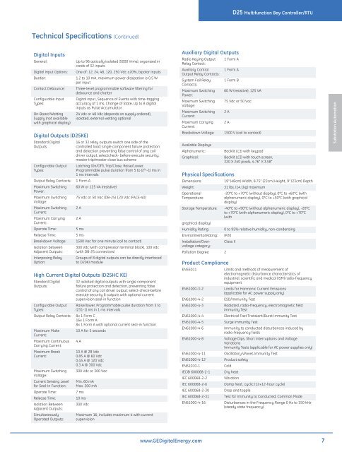
Technical Specifications (Continued)<br />
Digital Inputs<br />
General;<br />
Digital Input Options:<br />
Burden:<br />
Contact Debounce:<br />
Configurable Input<br />
Types:<br />
On-Board Wetting<br />
Supply (not available<br />
with graphical display):<br />
Digital Outputs (D25KE)<br />
Standard Digital<br />
Outputs:<br />
Configurable Output<br />
Types:<br />
Output Relay Contacts:<br />
Maximum Switching<br />
Power:<br />
Maximum Switching<br />
Voltage:<br />
Maximum Switching<br />
Current:<br />
Maximum Carrying<br />
Current:<br />
Operate Time:<br />
Release Time:<br />
Breakdown Voltage:<br />
Isolation between<br />
Adjacent Outputs:<br />
Interposing Relay<br />
Option:<br />
Up to 96 optically isolated (5000 Vrms), organized in<br />
cards of 32 inputs<br />
One of: 12, 24, 48, 120, 250 Vdc ±20%, bipolar inputs<br />
1.2 to 10 mA, maximum power dissipation is 0.5 W<br />
per input<br />
Three-level programmable software filtering for<br />
debounce and chatter<br />
Digital input, Sequence of Events with time-tagging<br />
accuracy of 1 ms, Change of State, Up to 8 digital<br />
inputs as Pulse Accumulator<br />
24 Vdc or 48 Vdc (depends on supply ordered),<br />
isolated, external wetting optional<br />
16 or 32 relay outputs switch one side of the<br />
controlled load; single component failure protection<br />
and detection preventing false control of any coil<br />
driver output; selectcheck- before execute security;<br />
master trip/master close bus scheme<br />
Latching (On/Off), Trip/Close, Raise/Lower,<br />
Programmable pulse duration from 5 to (2 31 -1) ms in<br />
1 ms intervals<br />
1 Form A<br />
60 W or 125 VA (resistive)<br />
75 Vdc or 50 Vac (DB-25) 120 Vdc (FACE-40)<br />
2 A<br />
2 A<br />
5 ms<br />
5 ms<br />
1500 Vac for one minute (coil to contact)<br />
300 Vdc (with compression terminal block), 100 Vdc<br />
(with DB-25 connectors)<br />
Groups of 8 digital outputs can be directly interfaced<br />
to D20KI module<br />
High Current Digital Outputs (D25HC KE)<br />
Standard Digital<br />
Outputs:<br />
Configurable Output<br />
Types:<br />
Output Relay Contacts:<br />
Maximum Make<br />
Current:<br />
Maximum Continuous<br />
Carrying Current:<br />
Maximum Break<br />
Current:<br />
Maximum Switching<br />
Voltage:<br />
Current Sensing Level<br />
for Seal-In Function:<br />
Operate Time:<br />
Release Time:<br />
Isolation Between<br />
Adjacent Outputs:<br />
Simultaneously<br />
Operated Outputs:<br />
32 isolated digital outputs with single component<br />
failure protection and detection, preventing false<br />
control of any coil driver output; select-check-before<br />
execute security 8 outputs with optional current<br />
supervision seal-in function<br />
Raise/lower, Programmable pulse duration from 5 to<br />
(231-1) ms in 1 ms intervals<br />
8x 1 Form C<br />
16x 1 Form A<br />
8x 1 Form A with optional current seal-in function<br />
10 A for 5 seconds<br />
4 A<br />
10 A @ 28 Vdc<br />
0.85 A @ 60 Vdc<br />
0.45 A @ 120 Vdc<br />
0.3 A @ 300 Vdc<br />
300 Vdc or 300 Vac<br />
Min. 60 mA<br />
Max. 200 mA<br />
7 ms<br />
10 ms<br />
300 Vdc<br />
Maximum 16, includes maximum 4 with current<br />
supervision<br />
Auxiliary Digital Outputs<br />
Radio Keying Output<br />
Relay Contact:<br />
Auxiliary <strong>Control</strong><br />
Output Relay Contacts:<br />
System Fail Relay<br />
Contacts:<br />
Maximum Switching<br />
Power:<br />
Maximum Switching<br />
Voltage:<br />
Maximum Switching<br />
Current:<br />
Maximum Carrying<br />
Current:<br />
Breakdown Voltage:<br />
Available Displays<br />
Alphanumeric:<br />
Graphical:<br />
1 Form A<br />
1 Form A<br />
1 Form B<br />
60 W (resistive), 125 VA<br />
75 Vdc or 50 Vac<br />
2 A<br />
2 A<br />
Physical Specifications<br />
1500 V (coil to contact)<br />
Backlit LCD with keypad<br />
Backlit LCD with touch screen,<br />
320 X 240 pixels, 4.76” X 3.58”<br />
Dimensions:<br />
19” (48cm) Width, 8.75” (22cm) Height, 9” (23cm) Depth<br />
Weight:<br />
31 lbs. (14.1kg) maximum<br />
Operational<br />
-20°C to +70°C (without display), 0°C to +60°C (with<br />
Temperature:<br />
alphanumeric display), 0°C to +50°C (with graphical<br />
display)<br />
Storage Temperature: -40°C to +90°C (without alphanumeric display), -20°C<br />
to +70°C (with alphanumeric display), 0°C to +70°C<br />
(with<br />
graphical display)<br />
Humidity Rating: 0 to 95% relative humidity, non-condensing<br />
Environmental Rating: IP20<br />
Installation/Overvoltage<br />
category:<br />
Class II<br />
Pollution Degree: 2<br />
Product Compliance<br />
EN55011<br />
EN61000-3-2<br />
EN61000-4-2<br />
EN61000-4-3<br />
EN61000-4-4<br />
EN61000-4-5<br />
EN61000-4-6<br />
EN61000-4-8<br />
EN61000-4-11<br />
EN61000-4-12<br />
EN61010-1<br />
IEC® 600068-2-1<br />
IEC 600068-2-2<br />
IEC 600068-2-6<br />
IEC 600068-2-30<br />
IEC 600068-2-31<br />
EN61000-4-16<br />
Limits and methods of measurement of<br />
electromagnetic disturbance characteristics of<br />
industrial, scientific and medical (ISM) radio-frequency<br />
equipment<br />
Limits for Harmonic Current Emissions<br />
(applicable for AC power supply only)<br />
ESD/Immunity Test<br />
Radiated, radio-frequency, electromagnetic field<br />
immunity Test<br />
Electrical Fast Transient/Burst Immunity Test<br />
Surge Immunity Test<br />
Immunity to conducted disturbances induced by<br />
radio-frequency fields<br />
Voltage Dips, Short Interruptions and Voltage<br />
Variations<br />
Immunity Tests (applicable for AC power supplies only)<br />
Oscillatory Waves Immunity Test<br />
Product safety<br />
Cold<br />
Dry heat<br />
Vibration<br />
Damp heat, cyclic (12+12-hour cycle)<br />
Drop and topple<br />
Test for Immunity to Conducted, Common Mode<br />
Disturbances in the Frequency Range 0 Hz to 150 kHz<br />
(steady state frequency).<br />
<strong>Substation</strong> <strong>Automation</strong><br />
www.GEDigitalEnergy.com<br />
7