
You also want an ePaper? Increase the reach of your titles
YUMPU automatically turns print PDFs into web optimized ePapers that Google loves.
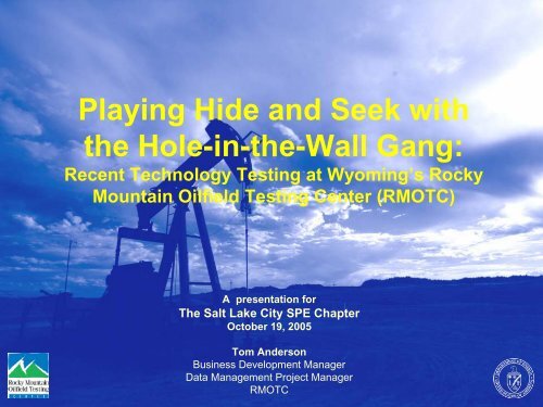
Playing Hide and Seek with<br />
the Hole-in-the-Wall Gang:<br />
Recent <strong>Technology</strong> Testing at Wyoming’s Rocky<br />
Mountain Oilfield Testing Center (<strong>RMOTC</strong>)<br />
A presentation for<br />
The Salt Lake City SPE Chapter<br />
October 19, 2005<br />
Tom Anderson<br />
Business Development Manager<br />
Data Management Project Manager<br />
<strong>RMOTC</strong>
Outline<br />
• What is <strong>RMOTC</strong>?<br />
• The Hole-in-the-Wall Gang<br />
• “Virtual Field Trip” of Teapot Dome<br />
• Hiding:<br />
–CO 2 Sequestration<br />
– Pipeline Leak Detection<br />
• Seeking:<br />
– Microhole Drilling<br />
– High Pressure Jet-Assisted Drillbit<br />
– Flow Assurance Test Loop<br />
– Tubing Rotator<br />
• Sharing Data With Partners
The Hole-in-the-Wall Gang<br />
Doug<br />
Jim<br />
Butch and<br />
Sundance<br />
Judith<br />
Mark<br />
Spike<br />
Ralph<br />
Wyoming<br />
Joe<br />
Vicki<br />
Brian<br />
Lyle
106°15'0"W<br />
106°15'0"W<br />
48-X-28<br />
71-1-X-4<br />
\A1;Flow Assurance Loop<br />
41-2-X-3<br />
67-1-X-1<br />
61-2-X-1<br />
25-1-X-1<br />
A Virtual Field Visit<br />
018<br />
017<br />
016<br />
015<br />
014 013<br />
018<br />
019<br />
020<br />
021<br />
022<br />
023<br />
024<br />
019<br />
030<br />
029<br />
028<br />
027<br />
026<br />
025<br />
030<br />
031<br />
032<br />
033<br />
034<br />
035<br />
036<br />
031<br />
006<br />
005<br />
004<br />
003<br />
002<br />
001<br />
006<br />
007<br />
008<br />
009<br />
010<br />
011<br />
012<br />
007<br />
018<br />
017<br />
016<br />
015<br />
014<br />
013<br />
018<br />
019<br />
43°15'0"N<br />
019<br />
020<br />
021<br />
022<br />
023<br />
024<br />
43°15'0"N<br />
030<br />
029 028<br />
027<br />
026<br />
025<br />
030<br />
Legend<br />
NPR3 Basemap<br />
0 0.2 0.4<br />
1:18,000<br />
0.6 0.8<br />
0.1<br />
Miles<br />
NPR3.dwg Polyline<br />
natronatwp<br />
natronasect<br />
Roads<br />
teapot_dem<br />
Value<br />
High : 5784.390625<br />
Low : 4827.637695<br />
Recent well locations
Hiding: CO2 Sequestration –<br />
Science Goals<br />
• NEEDS:<br />
– demonstration of storage safety and permanence<br />
– public safety, understanding and acceptance:<br />
• needed for wider deployment of geologic storage<br />
– site selection criteria, best practices<br />
– relationship / synergy with EOR<br />
• TEAPOT FOCUS AREAS:<br />
– site characterization and baseline assessment<br />
– leakage risk evaluation and prediction<br />
• behavior of fractures and faults<br />
• development of risk mitigation techniques<br />
– wellbore and cement integrity<br />
– sensitivity and detection limits of monitoring tools,<br />
recommended suites and practices<br />
– EOR/storage relationship
Project Plan<br />
PHASE 1, FY03 – 05 (complete):<br />
• Conceptual design for<br />
NPR-3 project<br />
• NPR-3 Reservoir /<br />
Geologic Characterization<br />
• Initiate development of<br />
Geologic Model<br />
• EOR Assessment and<br />
preliminary design<br />
• Preliminary Modeling of<br />
Target Zone<br />
• Baseline studies at NPR-3,<br />
data sharing with Salt<br />
Creek<br />
• Funding development<br />
PHASE 2: Proposed FY05-<br />
06, pending funds:<br />
• Detailed design<br />
• Submit proposals, secure<br />
permits<br />
• Bidding for construction<br />
• Initiate funded experiments<br />
PHASE 3: Proposed, starting<br />
FY06-07, pending funds:<br />
• EOR CO2 injection<br />
initiates, construction<br />
• Monitoring, measurement,<br />
verification<br />
• EOR / Storage research<br />
• <strong>Technology</strong> transfer
Existing infrastructure and data<br />
500 active wells, 1300 wells total, drilling rig & staff;<br />
Anadarko to supply low-cost CO 2 for experiments
NPR-3 Reservoir Summary<br />
9 Producing (oil-bearing) intervals<br />
• Depths 500’-5500’ (Shannon to<br />
Tensleep)<br />
• Miscible & immiscible floods<br />
• Good range of oil/rock chemistry<br />
• Range of rock composition &<br />
petrophysics<br />
Additional 5-6 water-bearing<br />
intervals<br />
• Fresh and saline, 3000-8000’<br />
• Range of dep. environments, clastic<br />
& carbonate<br />
• Crow Mt., Flathead, Sundance
Tensleep EOR / storage demonstration<br />
Compelling state and regional drivers to study<br />
storage in the Tensleep at Teapot Dome:<br />
• 2/3 of Wyoming’s production<br />
comes from Tensleep<br />
or equivalent<br />
• Rangely (Colorado) CO 2<br />
EOR in the Weber<br />
(Tensleep equiv.)<br />
• Significant volumes<br />
in Colorado & Utah<br />
• Analogs throughout<br />
U.S. & international
NPR-3 Gravity Stable Miscible CO2<br />
• Cost effective testing of gravity stable<br />
operation in Tensleep Formation<br />
– High relief structure<br />
– Significant fracturing<br />
– Active aquifer<br />
– Available wellbores for operation<br />
• Fluid analyzed and test design simulated<br />
– Laboratory tests used to generate equation of state<br />
for simulation tuning<br />
– Simulation at field scale and proposed test scale<br />
• Results support proceeding with injection
Saline Aquifer Storage Test<br />
• Saline aquifers as sinks:<br />
– International: Sleipner<br />
– U.S. DOE projects: Frio, Mountaineer<br />
• Crow Mountain Ss<br />
• Existing Class 2 wells, Section 10<br />
• Water analysis, permeability, caprock<br />
• Several surrounding wells possible for<br />
monitoring<br />
• Field Work Proposal in progress<br />
• Focus:<br />
– MMV tool sensitivity, comparison, and detection limits<br />
– Evaluation of multiple storage mechanisms
Baseline Assessments / Partner Research<br />
• CSM- Ron Klusman:<br />
– Soil gas and gas flux, baseline and monitoring phases<br />
• CSM- Neil Hurley:<br />
– LIDAR mapping of Tensleep outcrop<br />
• U of Md / LLNL- Julio Friedmann:<br />
– Fault seal / leakage risk assessment<br />
• U of Manchester- Chris Ballantine:<br />
– Noble gases as tracers (May 2005 field work)<br />
• USGS- Bob Burruss:<br />
– Reservoir compartmentalization and seepage assessment<br />
• U of Houston- Kurt Marfurt / Charlotte Sullivan:<br />
– 3D seismic data, curvature and attribute analysis for detailed<br />
fracture and fault understanding (initiated April 2005)<br />
• Princeton U:<br />
– CO2-cement interactions<br />
• LANL / LBNL / NETL:<br />
– Microdrilling and VSP monitoring applications
Reservoir Heterogeneity: LIDAR mapping<br />
A new laser-based surveying<br />
technique collects many millions<br />
of amplitude and XYZ data, which<br />
can render the outcrop in high<br />
detail.<br />
These data are being used to<br />
characterize the heterogeneity of<br />
the Tensleep SS, including<br />
fracture distribution & character.<br />
Colorado School of Mines
Reservoir Heterogeneity: LIDAR mapping<br />
These data have<br />
been processed<br />
for statistical<br />
information on<br />
fractures and<br />
bedding.<br />
Colorado School<br />
of Mines
Reservoir Characterization and<br />
Modeling High-level Task List<br />
• Meet with existing partners to<br />
define roles & responsibilities<br />
• Digitize logs from “deep wells”<br />
• Import wells and logs into<br />
GeoGraphix system<br />
• Build cross sections<br />
• Create structure maps<br />
• Do full 3D integrated seismic<br />
interpretation of multiple key<br />
horizons and faults<br />
• Do seismic depth conversion<br />
• Special geoscience analysis<br />
• Build a 3D geocellular model<br />
• Run dynamic flow simulation,<br />
perform history match and<br />
tune model for fit<br />
• Load production history and<br />
completions data into<br />
production mgmt system<br />
• Implement real-time<br />
production data capture and<br />
surveillance<br />
• Load (historic) drilling data<br />
into a system to enable<br />
improved drilling operations,<br />
planning and design<br />
• Instrument drilling rig for realtime<br />
operational data capture<br />
Yellow text means completed, white is still to be done
Example of initial<br />
subsurface structure<br />
map on the top<br />
Tensleep<br />
3D seismic time structure map<br />
for comparison
Sample Cross Section A-A’
-8.000<br />
-4.000<br />
0.000<br />
3D Seismic<br />
Amplitude<br />
Survey<br />
4.000<br />
8.000<br />
L<br />
221 211 203 195 186 178 170 161 153 144 134 125 L<br />
XL<br />
80 88 93 99 106 112 118 124 130 137 144 150 XL<br />
0.00 0.00<br />
0.10 0.10<br />
0.20 0.20<br />
? ?<br />
0.30 0.30<br />
Note data gaps in<br />
shallow part of survey<br />
Shannon?<br />
0.40 0.40<br />
0.50 0.50<br />
0.60 0.60<br />
0.70 0.70<br />
0.80 0.80<br />
0.90 0.90<br />
1.00 1.00<br />
1.10 1.10<br />
1.20 1.20<br />
1.30 1.30<br />
Second<br />
Wall Creek<br />
Lakota<br />
Sundance<br />
Tensleep<br />
Basement<br />
1.40 1.40
University of<br />
Houston,<br />
Allied<br />
Geophysical<br />
Laboratories<br />
890 ms<br />
Curvature time slice<br />
890 ms<br />
Coherency time slice
New Visualization Methods<br />
Slide courtesy of Transform Software and Services
BYU High-Resolution Seismic<br />
• 48-channel (24 fold)<br />
• 10-ft station intervals<br />
(5 ft. CDP)<br />
• 28-Hz phones<br />
• Conventional CDP<br />
roll-along (internal<br />
software switch)<br />
• Accelerated weight<br />
drop (with 100 lb.<br />
hammer)<br />
• 2 Profiles (each about<br />
3/4 mile long)<br />
Graduate student: John South
Section<br />
34 area<br />
Location of BYU High-Res Seismic<br />
Seismic<br />
2D lines
Example of High-Resolution Seismic<br />
from BYU<br />
This is not<br />
from Teapot<br />
Dome, but<br />
illustrates the<br />
kind of detail<br />
we expect to<br />
see in the<br />
shallow<br />
seismic lines<br />
they shot at<br />
NPR3 (which<br />
are not yet<br />
processed).
Section 34 Subsurface Interpretation<br />
Well log cross section above<br />
BYU 2D seismic cross sections
Pipeline Leak Detection<br />
Sensor companies participating:<br />
• En’Urga Inc.<br />
• ITT Industries, Inc.<br />
• LaSen, Inc.<br />
• Lawrence Livermore National Laboratory<br />
• Physical Sciences Inc.<br />
S O U T H W E S T R E S E A R C H I N S T I T U T E ®<br />
SAN ANTONIO<br />
DETROIT<br />
HOUSTON<br />
WASHINGTON, DC
Objectives<br />
• Provide a forum where developers of remote sensor,<br />
natural gas leak detection systems would be able to test<br />
or demonstrate the operation of their systems.<br />
• Form an advisory panel of interested gas company<br />
personnel.<br />
• Develop a test plan, including the development of a<br />
“virtual” pipeline and leak site-specific designs.<br />
• Conduct the field tests, where the equipment providers<br />
collect their own data.
Advisory Board<br />
• American Gas Association<br />
• Department of Energy, National Energy<br />
<strong>Technology</strong> Laboratory<br />
• El Paso Pipeline Group<br />
• Northeast Gas Association<br />
• Office of Pipeline Safety, Department of<br />
Transportation<br />
• Pacific Gas & Electric Company<br />
• Pipeline Research Council International, Inc.<br />
• Southwest Research Institute
0<br />
500' 1000'<br />
0<br />
500' 1000'<br />
North end of virtual pipeline<br />
18 17<br />
19 20<br />
N<br />
14 13<br />
23 24<br />
20<br />
B-1-20<br />
21<br />
To Midwest 7 Mi.<br />
22<br />
23 24<br />
26 25<br />
Hwy 259<br />
29<br />
28<br />
27<br />
33<br />
34<br />
To Casper 31 Mi.<br />
Scale:<br />
33<br />
34<br />
Scale:<br />
Passes gas plant<br />
34<br />
34<br />
3<br />
2<br />
Vortex LLC Project<br />
Car Wash (SG 2)<br />
10<br />
10<br />
11<br />
VIRTUAL<br />
PIPELINE MAP<br />
7 8<br />
18 17<br />
Scale:<br />
0 500 1000 1500 2000 2500 Ft.<br />
0 1/4 1/2 Mi.<br />
LEGEND<br />
Primary Roads<br />
NPR-3 Boundary<br />
16<br />
9<br />
14<br />
(Naval Petroleum Reserve No. 3)<br />
16<br />
Calibration leak site 25-STX-3<br />
23<br />
27
Virtual Pipeline Leak Sites<br />
Leak<br />
Site<br />
Gas Source<br />
Leak Type<br />
Latitude<br />
(N)<br />
Longitude<br />
(W)<br />
DISTANCE FROM<br />
LEAK SITE TO<br />
CENTER OF<br />
ROAD (FT)<br />
Side of<br />
Road<br />
1 <strong>RMOTC</strong> gas Below ground 43 14 53.6 106 11 12.1 36 East<br />
2A Cylinder Below ground 43 15 12.9 106 11 50.1 76 West<br />
2B Cylinder Below ground 43 15 26.3 106 11 59.9 78 West<br />
2C Cylinder Below ground 43 15 46.0 106 12 09.1 122 East<br />
3 <strong>RMOTC</strong> gas Aboveground 43 16 15.7 106 12 19.5 44 East<br />
4 <strong>RMOTC</strong> gas Below ground 43 16 20.1 106 12 24.6 90 East<br />
2D/1F Cylinder Below ground 43 16 34.4 106 12 43.2 100 East<br />
5 <strong>RMOTC</strong> gas Below ground 43 17 44.1 106 13 15.8 59 East<br />
P1 <strong>RMOTC</strong> gas Side-drilled 43 18 12.7 106 13 06.3 78 West<br />
P2 <strong>RMOTC</strong> gas Side-drilled 43 18 37.0 106 13 17.9 240 West<br />
6 <strong>RMOTC</strong> gas Below ground 43 18 56.4 106 13 30.4 170 West<br />
2E Cylinder Below ground 43 19 12.4 106 13 40.3 74 East<br />
P3 <strong>RMOTC</strong> gas Side-drilled 43 19 44.5 106 13 51.5 116 West<br />
P4 <strong>RMOTC</strong> gas Side-drilled 43 20 13.2 106 13 37.8 66 West<br />
P5 Cylinder Side-drilled 43 20 27.7 106 13 36.3 39 West
10 feet<br />
Underground leak outlet<br />
is roughly 10 feet from<br />
rotometer location (in<br />
gravel area).<br />
View of bottle and regulator<br />
View of leak site<br />
and vegetation.
Summary<br />
• The “virtual pipeline” route was defined, including<br />
leak sites.<br />
• Specific leak details were developed for the 15<br />
different leak sites. Some of the leak sites were<br />
designed to release gas at the roots of plants in<br />
order to provide the required test conditions for one<br />
of the detection systems. The leak rates ranged<br />
from 1 sfch to 5,000 scfh.<br />
• Where appropriate, leak equipment was hidden<br />
from plain view when traveling along the road. In<br />
addition, decoy piping was installed at sites that<br />
were not intended as true leak sites.
Leak Determination by Leak Rate<br />
Leak<br />
Rate<br />
No. of<br />
Leaks<br />
Presented<br />
No. of<br />
Leaks<br />
Found<br />
Leak<br />
Find %<br />
No. of<br />
Calibration<br />
Leaks<br />
No. of<br />
Calibration<br />
Leaks Found<br />
Calibration<br />
Leak Find<br />
%<br />
5,000 15 13 87 6 6 100<br />
2,500 4 2 50 0 0 N/A<br />
2,000 20 14 70 0 0 N/A<br />
1,000 43 27 63 6 5 83<br />
500 43 27 63 6 5 83<br />
100 39 5 13 5 5 100<br />
15 33 2 6 3 2 67<br />
10 25 2 8 0 0 N/A<br />
1 25 0 0 0 0 N/A
Instrumentation Sensitivity to Leak Rates<br />
100<br />
90<br />
500 scfh found 50-87%<br />
Percent Found<br />
80<br />
70<br />
60<br />
50<br />
40<br />
30<br />
20<br />
10<br />
0<br />
Important Points<br />
• Vendors were asked to identify sites that they believed<br />
were natural gas pipeline leaks, which were matched up<br />
with the intended leaks for that day. “Positive”<br />
indications that did not correspond with leak sites were<br />
investigated. Most of these sites did not contain gas,<br />
but were old water pipes, fence posts, abandoned well<br />
sites, patches of dirt, etc.<br />
• There was evidence that some of the equipment<br />
providers may have been using visual clues to look for<br />
leaks, as opposed to conducting a “blind” search,<br />
accounting for some of the false positives reported.<br />
• You can access the full report at:<br />
http://www.rmotc.com/Library/Test_Reports.html<br />
Under “Energy Assurance”, “Remote Sensor Gas LDS” (PDF)<br />
Thanks to: Rodney Anderson and Rick Baker (DOE NETL)
Seeking (New <strong>Technology</strong>):<br />
Microhole Drilling
Micro-drilling Site at <strong>RMOTC</strong>: From left to right: the Los Alamos<br />
drilling mud cleaning system and the Los Alamos coiled tubing<br />
drilling rig. In the foreground is the reserve pit and flush-joint<br />
tubing to be run as production casing for a Shannon oil well.
Los Alamos Microdrilling Field Team and coiled tubing unit.<br />
From left to right Jim Thomson and Dave Anderson.
The Los Alamos coiled tubing drilling rig with 1-in. coiled tubing running<br />
through the stuffing-box drilling-mud diverter that conducts high<br />
pressure drilling mud to a hydraulic motor and bit on the bottom of the<br />
coiled tubing. The hose in the foreground is the flow line that conducts<br />
the drilling mud returns from the well annulus to the mud cleaning unit.
A <strong>RMOTC</strong> pulling unit<br />
and Los Alamos coiled<br />
tubing unit rigged up<br />
simultaneously over a<br />
well drilled in<br />
September 2003. The<br />
pulling unit was used to<br />
run a string of steel<br />
flush joint casing; the<br />
coiled-tubing unit made<br />
a clean-out run<br />
following cementing.
Dennis Tool Company equipment being tested on the Los Alamos<br />
coiled tubing micro-drilling rig. From left to right: 1-3/4-in. pilot bit,<br />
2-3/8-in. reamer, and crossover sub to mate equipment to Los<br />
Alamos drilling assembly.
Dennis Tool Company<br />
equipment assembled on an<br />
atypical Los Alamos microdrilling<br />
drilling assembly.<br />
From bottom to top: Dennis<br />
Tool 1-3/4-in. pilot bit, 1-7/16-<br />
in. single-lobe OD drilling<br />
motor, Dennis Tool 1 11/16-in.<br />
OD stabilizer integral to 2-3/8-<br />
in. reamer, and 2-1/4-in. OD<br />
stabilizer.
Lawrence Berkeley Lab –<br />
Vertical Seismic Profile
Foreground. LBNL Microgeophone array sonde between sections of the<br />
deployment cable. Backgound. Contract vibroseis unit with a 16000 lb<br />
amplitude and a sweep range of 10 to 200 Hz.
High Pressure Jet-Assisted Drillbit<br />
• Early Attempts in<br />
1970’s<br />
• Uses high pressure<br />
(8,000 psi) to cut<br />
formation ahead of bit<br />
• Bit knocks off ledges<br />
• High rates of<br />
penetration
<strong>RMOTC</strong> Test Results<br />
• Mechanical<br />
difficulties with<br />
loss of jets in<br />
bits<br />
• Surface<br />
mechanical<br />
problems fixed<br />
• Increases in<br />
penetration<br />
rates of 2 -6<br />
times over a<br />
variety of<br />
formations<br />
Drilling Rate (ft/hr)<br />
160<br />
140<br />
120<br />
100<br />
80<br />
60<br />
40<br />
20<br />
0<br />
156.0<br />
120.0<br />
Crow<br />
Mountain<br />
Sand<br />
49.8<br />
55.1<br />
High Pressure Drilling vs Conventional<br />
77.7<br />
61.9<br />
66.0<br />
39.8 39.3<br />
13.5 14.8 12.9 13.3 13.8 14.1 14.1<br />
Crow<br />
Mountain<br />
Sand/Alcova<br />
Limestone<br />
Red Peaks<br />
Shale<br />
Red Peaks<br />
Shale<br />
Formation<br />
Red Peaks<br />
Shale<br />
Red Peaks<br />
Shale<br />
Jet Assisted Drilling Rate<br />
Conventional Drilling Rate<br />
Rate Ratio<br />
Red Peaks<br />
Shale<br />
Goose Egg<br />
8<br />
7<br />
6<br />
5<br />
4<br />
3<br />
2<br />
1<br />
0<br />
Drilling Rate Ratio
106°15'0"W<br />
106°15'0"W<br />
Flow Assurance Test Loop<br />
018<br />
017<br />
016<br />
015<br />
014 013<br />
018<br />
019<br />
020<br />
021<br />
022<br />
023<br />
024<br />
019<br />
030<br />
029<br />
028<br />
027<br />
026<br />
025<br />
030<br />
031<br />
032<br />
033<br />
034<br />
035<br />
036<br />
031<br />
Schematic<br />
006<br />
005<br />
004<br />
003<br />
002<br />
001<br />
006<br />
\A1;Flow Assurance Loop<br />
007<br />
008<br />
009<br />
010<br />
011<br />
012<br />
007<br />
018<br />
017<br />
016<br />
015<br />
014<br />
013<br />
018<br />
019<br />
43°15'0"N<br />
019<br />
020<br />
021<br />
022<br />
023<br />
024<br />
43°15'0"N<br />
030<br />
029 028<br />
027<br />
026<br />
025<br />
030<br />
NPR3 Basemap<br />
0 0.2 0.4<br />
1:18,000<br />
0.6 0.8<br />
0.1<br />
Miles<br />
Legend<br />
NPR3.dwg Polyline<br />
natronatwp<br />
natronasect<br />
Roads<br />
Hillshade of teapot_dem<br />
Value<br />
High : 255<br />
Low : 0
Concentric Pipe Jacketed Section<br />
6 inch, 3600 psi rated, inside of 10 inch, to enable heating<br />
and cooling fluid circulation; 190° F produced water available
Bell Holes and Instrumentation<br />
Trenching Hazards<br />
• Pressure/temperature<br />
gauges of the Rosemount<br />
and quartz crystal absolute<br />
pressure types.<br />
• Test section temperature is<br />
sensed by a collateral fiber<br />
optics line.<br />
• Nitrogen-filled pressure<br />
reference line.<br />
• Dual station gamma ray for<br />
hydrate holdup and speed.
Setup for Generating Hydrate Plug
Gas Supply, Dehydrator,<br />
and Operational Pad
Success!<br />
Subsequent mitigation<br />
tests conducted with a<br />
major oil company<br />
(still confidential)<br />
were also successful<br />
at proving their cleanout<br />
technology.
Energy Production Systems<br />
Tubing Rotator System<br />
Why did EPS choose <strong>RMOTC</strong> for testing?<br />
• Availability of a “problem” well with<br />
significant tubing failure rates.<br />
• Available rigs and crews.<br />
• Detailed well service records.<br />
• Ability to accurately measure well<br />
performance and calculate economic<br />
benefits.<br />
•Ability to accurately quantify post-test<br />
tubing wear data.<br />
•Tech transfer opportunities.
24-AX-10: A Problem Well<br />
• Deviated wellbore, resulting in<br />
high tubing and rod wear rates.<br />
• Holed tubing resulting in lost<br />
production.<br />
• Parted rods and rod couplings.<br />
• Frequent well pulls resulting in<br />
production downtime and<br />
increased operating costs.<br />
• Reduced well operating cycles.<br />
• Economics dictate plans for<br />
abandonment.<br />
The Testing Plan:<br />
• Install all new tubing, rods, and<br />
pump.<br />
• Install a new EPS Tubing<br />
Rotator System.<br />
• Put the well on a 24/7 pumping<br />
cycle.<br />
• Operate continuously for one<br />
year or until failure, whichever<br />
comes first.<br />
• Measure tubing wall thickness<br />
at end of test.<br />
• Return well to production.
Rotating Tubing Hanger
The Key to Success: Tubing Rotator Anchor
Well 24-AX-10 Production History<br />
Down periods due to tubing failures<br />
Addition of EPS Tubing Rotator System, 10/04
The Results<br />
24-AX-10 PRODUCTION SINCE INSTALLATION OF<br />
THE EPS TUBING ROTATOR SYSTEM<br />
10000<br />
1000<br />
BPM<br />
100<br />
10<br />
1<br />
Sep-<br />
04<br />
Oct-<br />
04<br />
Nov-<br />
04<br />
Dec-<br />
04<br />
Jan-<br />
05<br />
Feb-<br />
05<br />
Mar-<br />
05<br />
Apr-<br />
05<br />
May-<br />
05<br />
Jun-<br />
05<br />
Jul-<br />
05<br />
Aug-<br />
05<br />
BOPM<br />
BWPM
12 Month 24/7<br />
Post-Test Tuboscope<br />
Tubing Wear Analysis<br />
The bottom four joints had wall loss<br />
>50%.<br />
94 th joint had 69% wall loss.<br />
Failure of the 94 th joint is predicted<br />
for March 2006, after 16 months of<br />
24/7 operation.<br />
This failure rate is a 400%<br />
improvement over that predicted by<br />
well history.<br />
94 th joint
<strong>RMOTC</strong> Datasets<br />
3D Seismic<br />
Teapot Dome<br />
Natrona County, Wyoming<br />
3-D Seismic Data Set<br />
Core Data<br />
Teapot Dome<br />
Natrona County, Wyoming<br />
Core Data Set from<br />
Well 48-X-28<br />
Teapot Dome<br />
Natrona County, Wyoming<br />
NPR-3 Deep Well Data Set<br />
Deep Wells<br />
(LAS files)