PCITS2000/2 Primary Current Injection Test Sets - Maxtech
PCITS2000/2 Primary Current Injection Test Sets - Maxtech
PCITS2000/2 Primary Current Injection Test Sets - Maxtech

You also want an ePaper? Increase the reach of your titles
YUMPU automatically turns print PDFs into web optimized ePapers that Google loves.
<strong>PCITS2000</strong>/2<br />
<strong>Primary</strong> <strong>Current</strong> <strong>Injection</strong> <strong>Test</strong> <strong>Sets</strong><br />
<strong>PCITS2000</strong>/2<br />
<strong>Primary</strong> <strong>Current</strong> <strong>Injection</strong> <strong>Test</strong> <strong>Sets</strong><br />
■<br />
■<br />
■<br />
<strong>Test</strong> relay protection systems and their<br />
current transformers together<br />
<strong>Current</strong> level maintained though test<br />
circuit resistance may rise due to heating<br />
Built-in timer to record protection relay<br />
operation<br />
DESCRIPTION<br />
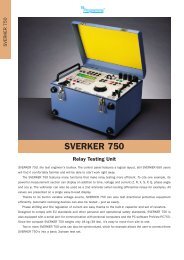
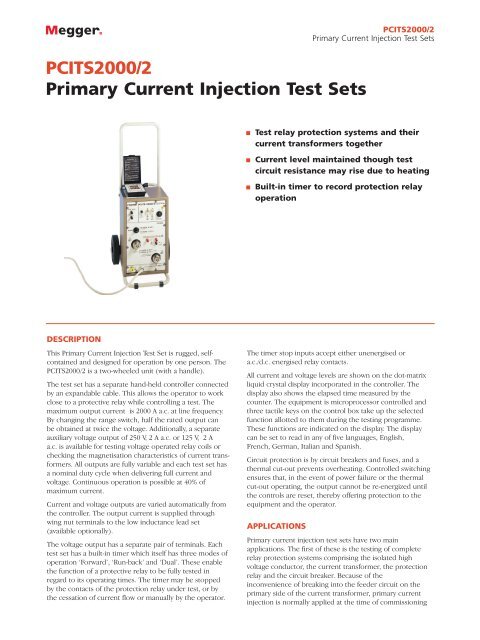
This <strong>Primary</strong> <strong>Current</strong> <strong>Injection</strong> <strong>Test</strong> Set is rugged, selfcontained<br />
and designed for operation by one person. The<br />
<strong>PCITS2000</strong>/2 is a two-wheeled unit (with a handle).<br />
The test set has a separate hand-held controller connected<br />
by an expandable cable. This allows the operator to work<br />
close to a protective relay while controlling a test. The<br />
maximum output current is 2000 A a.c. at line frequency.<br />
By changing the range switch, half the rated output can<br />
be obtained at twice the voltage. Additionally, a separate<br />
auxiliary voltage output of 250 V, 2 A a.c. or 125 V, 2 A<br />
a.c. is available for testing voltage operated relay coils or<br />
checking the magnetisation characteristics of current transformers.<br />
All outputs are fully variable and each test set has<br />
a nominal duty cycle when delivering full current and<br />
voltage. Continuous operation is possible at 40% of<br />
maximum current.<br />
<strong>Current</strong> and voltage outputs are varied automatically from<br />
the controller. The output current is supplied through<br />
wing nut terminals to the low inductance lead set<br />
(available optionally).<br />
The voltage output has a separate pair of terminals. Each<br />
test set has a built-in timer which itself has three modes of<br />
operation ‘Forward’, ‘Run-back’ and ‘Dual’. These enable<br />
the function of a protective relay to be fully tested in<br />
regard to its operating times. The timer may be stopped<br />
by the contacts of the protection relay under test, or by<br />
the cessation of current flow or manually by the operator.<br />
The timer stop inputs accept either unenergised or<br />
a.c./d.c. energised relay contacts.<br />
All current and voltage levels are shown on the dot-matrix<br />
liquid crystal display incorporated in the controller. The<br />
display also shows the elapsed time measured by the<br />
counter. The equipment is microprocessor controlled and<br />
three tactile keys on the control box take up the selected<br />
function allotted to them during the testing programme.<br />
These functions are indicated on the display. The display<br />
can be set to read in any of five languages, English,<br />
French, German, Italian and Spanish.<br />
Circuit protection is by circuit breakers and fuses, and a<br />
thermal cut-out prevents overheating. Controlled switching<br />
ensures that, in the event of power failure or the thermal<br />
cut-out operating, the output cannot be re-energized until<br />
the controls are reset, thereby offering protection to the<br />
equipment and the operator.<br />
APPLICATIONS<br />
<strong>Primary</strong> current injection test sets have two main<br />
applications. The first of these is the testing of complete<br />
relay protection systems comprising the isolated high<br />
voltage conductor, the current transformer, the protection<br />
relay and the circuit breaker. Because of the<br />
inconvenience of breaking into the feeder circuit on the<br />
primary side of the current transformer, primary current<br />
injection is normally applied at the time of commissioning
<strong>PCITS2000</strong>/2<br />
<strong>Primary</strong> <strong>Current</strong> <strong>Injection</strong> <strong>Test</strong> <strong>Sets</strong><br />
protection equipment or after major repair. Routine testing<br />
is carried out using secondary current injection with<br />
equipment such as the SCITS100 (100 A) or SCITS50D<br />
(50 A).<br />
As many of the protection systems requiring testing have a<br />
critical performance in relation to time, the primary<br />
current injection test sets incorporate a time counter<br />
facility.<br />
The second role of the primary current injection test set is<br />
in the testing of the current transformer in a protection<br />
system. Again, this test is normally applied prior to<br />
commissioning equipment or after repair.<br />
In addition to these protection system applications, current<br />
injection test sets are ideal for any application where it is<br />
necessary to supply a low resistance load with a<br />
controlled and measured heavy current.<br />
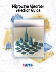
<strong>Primary</strong> or Secondary <strong>Test</strong>ing, Which?<br />
<strong>Primary</strong> <strong>Injection</strong> <strong>Test</strong>ing<br />
Most electricity supply protective equipment is fed from a<br />
current transformer on the supply cable or busbar. <strong>Primary</strong><br />
current injection testing checks all the components of the<br />
protective system. A high test current, enough to cause the<br />
protection equipment to operate, in injected into the<br />
supply cable. Time taken for the protection relay to<br />
operate is then measured.<br />
The primary current injection test is essential when<br />
commissioning new protection systems and after major<br />
repair and component replacement, since it tests the<br />
whole system. It will detect current transformers<br />
connected with incorrect polarity or relays that have been<br />
set in the wrong sequence in differential systems.<br />
However, the inconvenience of breaking the primary<br />
circuit means that the method is unsuitable for routine<br />
testing.<br />
Secondary <strong>Injection</strong> <strong>Test</strong>ing<br />
Secondary current injection testing checks the operation of<br />
the protective relay etc. but does not test the overall<br />
system including the current transformer. <strong>Primary</strong> testing<br />
usually requires a high current (over 500 A). A secondary<br />
injection test is easier since there is not the need to break<br />
the primary circuit and it requires a lower current (up to<br />
100 A) through the operating coil of the protective device.<br />
The time taken for the protection device to operate is then<br />
measured.<br />
A test winding is sometimes provided on the current<br />
transformer through which the secondary testing can be<br />
carried out.
<strong>PCITS2000</strong>/2<br />
<strong>Primary</strong> <strong>Current</strong> <strong>Injection</strong> <strong>Test</strong> <strong>Sets</strong><br />
SPECIFICATIONS<br />
Maximum <strong>Current</strong> Output a.c.<br />
<strong>PCITS2000</strong>/2<br />
2000 A at 0 to 3 V, 50 Hz/60 Hz<br />
1000 A at 0 to 6 V, 50 Hz/60 Hz<br />
Setting Resolution 10 A<br />
Auxiliary Voltage Output a.c.<br />
0 to 250 V, 2 A, 50 Hz/60 Hz<br />
0 to 125 V, 2 A, 50 Hz/60 Hz<br />
Display<br />
Dot matrix L.C.D.<br />
<strong>Current</strong> Range<br />
0–2000 A, resolution 1 A<br />
Temperature Range<br />
Operation:<br />
0°C to 40°C (32 to 104°F)<br />
Storage:<br />
-20°C to +60°C (-4 to 140°F)<br />
Humidity Range<br />
Operation:<br />
90% RH at 40°C (104°F)<br />
Storage:<br />
93% RH at 40°C (104°F)<br />
Supply Voltage<br />
220 V/240 V +6% –10%, 50 Hz/60 Hz<br />
7 kVA<br />
Controller Supply Fuse:<br />
1 A ceramic HBC 20 mm x 5 mm IEC 127/1<br />
Dimensions<br />
320 mm x 305 mm x 510 mm<br />
(12 1 /2 in x 12 in x 20 in approx.)<br />
excluding handle and wheels.<br />
Controller<br />
202 mm x 127 mm x 55 mm<br />
(8 in x 5 in x 2 1 /8 in approx.)<br />
Weight<br />
61 kg (134 lb approx.)<br />
Auxiliary Voltage Range<br />
0–250 V, resolution 1 V;<br />
0–2 A, resolution 0,01 A<br />
Accuracy:<br />
±3% of reading, ±2 digits.<br />
Timer:<br />
0–600 s, resolution 0,01 s<br />
Accuracy:<br />
±0.1%, ±0.05 s<br />
Duty Cycle<br />
21/2 minutes on circuit and 15 minutes off<br />
circuit at full range current and voltage.<br />
Duty cycle increases until continuous use<br />
is possible at 40% of full range.<br />
Timer Stop Inputs<br />
Unenergised or 100 V to 264 V a.c./d.c.<br />
energised contacts.<br />
Safety<br />
The test set will, in general, meet the<br />
requirements of the IEC1010-1 (1990)<br />
specification.<br />
Equipment Protection<br />
Circuit Breakers:<br />
30 A rating<br />
Auxiliary Output Fuse:<br />
2 A ceramic HBC 20 mm x 5 mm IEC 127/1<br />
X<br />
current<br />
transformer<br />
X<br />
time<br />
delay<br />
current<br />
transformer<br />
X<br />
open<br />
circuit here<br />
X<br />
test winding<br />
time<br />
delay<br />
inject<br />
current here<br />
inject current here<br />
time<br />
delay<br />
inject current here<br />
<strong>Primary</strong> <strong>Injection</strong> <strong>Test</strong>ing Secondary <strong>Injection</strong> <strong>Test</strong>ing Secondary testing with test winding<br />
Item<br />
<strong>Primary</strong> <strong>Current</strong> <strong>Injection</strong> <strong>Test</strong> <strong>Sets</strong><br />
ORDERING INFORMATION<br />
Order Code Item<br />
Order Code<br />
<strong>PCITS2000</strong>/2 Optional Accessories<br />
2000 A low inductance lead set (3 m long) 6220-462<br />
Timer/low current leadset 6220-125<br />
Registered to ISO 9001:2000 Reg no. Q 09290<br />
Registered to ISO 14001 Reg no. EMS 61597<br />
<strong>PCITS2000</strong>_2_DS_en_V10<br />
www.megger.com<br />
Megger is a registered trademark